EP2561596B1 - System and method for enhanced watch dog in solar panel installations - Google Patents
System and method for enhanced watch dog in solar panel installationsDownload PDFInfo
- Publication number
- EP2561596B1 EP2561596B1EP11772811.3AEP11772811AEP2561596B1EP 2561596 B1EP2561596 B1EP 2561596B1EP 11772811 AEP11772811 AEP 11772811AEP 2561596 B1EP2561596 B1EP 2561596B1
- Authority
- EP
- European Patent Office
- Prior art keywords
- solar
- module
- voltage
- string
- management unit
- Prior art date
- Legal status (The legal status is an assumption and is not a legal conclusion. Google has not performed a legal analysis and makes no representation as to the accuracy of the status listed.)
- Active
Links
Images


Classifications
- H—ELECTRICITY
- H02—GENERATION; CONVERSION OR DISTRIBUTION OF ELECTRIC POWER
- H02S—GENERATION OF ELECTRIC POWER BY CONVERSION OF INFRARED RADIATION, VISIBLE LIGHT OR ULTRAVIOLET LIGHT, e.g. USING PHOTOVOLTAIC [PV] MODULES
- H02S50/00—Monitoring or testing of PV systems, e.g. load balancing or fault identification
- G—PHYSICS
- G01—MEASURING; TESTING
- G01R—MEASURING ELECTRIC VARIABLES; MEASURING MAGNETIC VARIABLES
- G01R31/00—Arrangements for testing electric properties; Arrangements for locating electric faults; Arrangements for electrical testing characterised by what is being tested not provided for elsewhere
- H—ELECTRICITY
- H02—GENERATION; CONVERSION OR DISTRIBUTION OF ELECTRIC POWER
- H02J—CIRCUIT ARRANGEMENTS OR SYSTEMS FOR SUPPLYING OR DISTRIBUTING ELECTRIC POWER; SYSTEMS FOR STORING ELECTRIC ENERGY
- H02J3/00—Circuit arrangements for AC mains or AC distribution networks
- H02J3/38—Arrangements for parallely feeding a single network by two or more generators, converters or transformers
- H—ELECTRICITY
- H02—GENERATION; CONVERSION OR DISTRIBUTION OF ELECTRIC POWER
- H02S—GENERATION OF ELECTRIC POWER BY CONVERSION OF INFRARED RADIATION, VISIBLE LIGHT OR ULTRAVIOLET LIGHT, e.g. USING PHOTOVOLTAIC [PV] MODULES
- H02S50/00—Monitoring or testing of PV systems, e.g. load balancing or fault identification
- H02S50/10—Testing of PV devices, e.g. of PV modules or single PV cells
- H—ELECTRICITY
- H10—SEMICONDUCTOR DEVICES; ELECTRIC SOLID-STATE DEVICES NOT OTHERWISE PROVIDED FOR
- H10F—INORGANIC SEMICONDUCTOR DEVICES SENSITIVE TO INFRARED RADIATION, LIGHT, ELECTROMAGNETIC RADIATION OF SHORTER WAVELENGTH OR CORPUSCULAR RADIATION
- H10F77/00—Constructional details of devices covered by this subclass
- H10F77/95—Circuit arrangements
- H10F77/953—Circuit arrangements for devices having potential barriers
- H10F77/955—Circuit arrangements for devices having potential barriers for photovoltaic devices
- H—ELECTRICITY
- H04—ELECTRIC COMMUNICATION TECHNIQUE
- H04B—TRANSMISSION
- H04B2203/00—Indexing scheme relating to line transmission systems
- H04B2203/54—Aspects of powerline communications not already covered by H04B3/54 and its subgroups
- H04B2203/5429—Applications for powerline communications
- H04B2203/5458—Monitor sensor; Alarm systems
- Y—GENERAL TAGGING OF NEW TECHNOLOGICAL DEVELOPMENTS; GENERAL TAGGING OF CROSS-SECTIONAL TECHNOLOGIES SPANNING OVER SEVERAL SECTIONS OF THE IPC; TECHNICAL SUBJECTS COVERED BY FORMER USPC CROSS-REFERENCE ART COLLECTIONS [XRACs] AND DIGESTS
- Y02—TECHNOLOGIES OR APPLICATIONS FOR MITIGATION OR ADAPTATION AGAINST CLIMATE CHANGE
- Y02E—REDUCTION OF GREENHOUSE GAS [GHG] EMISSIONS, RELATED TO ENERGY GENERATION, TRANSMISSION OR DISTRIBUTION
- Y02E10/00—Energy generation through renewable energy sources
- Y02E10/50—Photovoltaic [PV] energy
- Y02E10/56—Power conversion systems, e.g. maximum power point trackers
Definitions
- the present inventionrelates to the field of electrical safeguards for photovoltaic systems.
- a lethal voltage potentialmay be present.
- the possible voltagecould be as high as 600 volts, while in Europe and the rest of the world this voltage could approach a kilovolt.
- Another recommendationis to install and/or service the photovoltaic panels at night when there is minimal risk of the panels being energized. This approach presents the potential safety risks associated from working in a poorly lighted environment.
- Patent application WO2009/006879describes a photovoltaic system having a plurality of photovoltaic elements electrically connected to one another and electrical lines for providing electrical current.
- Patent application DE 10 2005 018173(A1 ) describes a method involving attaching a switching device in direct proximity to a generator field within or outside a structure.
- the fieldis shortcircuited by a control line which is activated manually or automatically.
- the fieldstands in a safe operating point in which energy transfer in the structure is not allowed.
- the deviceswitches the field on demand into the low-energy operating point by the control line.
- Patent application DE 10 2008 003272(A1 ) describes a monitoring unit which has a function monitoring system, and a conversion module directly converting radiation energy i.e. solar energy, into electric energy.
- the monitoring unitis centrally monitored and recorded from a controlling computer, where the monitoring unit is arranged at a set of photovoltaic modules (1-3).
- a set of function modulesis arranged at each of the photovoltaic modules, so that the function modules are interchanged during the interchange of the photovoltaic modules and are arranged in connection boxes (4-6).
- Patent application US 2010/071274describes a unitized curtain wall unit which is adapted to incorporate power generating elements within an exterior shell or façade of a building structure.
- the unitscan also be adapted to house other power generating system components-including control units and associated power/signal wiring.
- One example of the disclosureprovides a method and system to reduce the safety risks during the shipment, installation and/or maintenance of photovoltaic systems, without introducing the risks associated with other approaches, such as covering them with an opaque material or working on them at night.
- safety protectionis provided via the inclusion of a normally closed switch integral to the panel junction box or integral to the panel module when alternating current (AC) or direct current (DC) modules are used.
- ACalternating current
- DCdirect current
- FIG. 1illustrates a solar panel having a safety switch according to one example.
- a solar panel 10e.g., a photovoltaic panel
- includes at least one solar cell 12e.g., a photovoltaic cell
- a voltage module 14to adjust or regulate the output voltage (or in some other cases a current module to regulate current)
- a switch 16to selectively isolate the solar cell 12 from the output connectors of the solar panel.
- the switchmay be incorporated into regulator modules, such as voltage module 14.
- the switch 16is a normally closed switch. During the shipment, installation and/or maintenance, the switch 16 is placed in an open state to isolate the solar cell 12 from the output. After the installation or maintenance, the switch 16 is placed into a closed state to allow the solar cell 12 to energize the output connectors of the solar panel and to supply power through the output connectors of the solar panel.
- the switch 16 and the voltage modulecan be integrated into the junction box of the solar panel.
- the switch 16is integrated with the voltage module 14 as a panel module.
- Figures 2 through 5illustrate a spring loaded safety switch for a photovoltaic panel according to one example.
- the switchincludes two contactors 102 and 103 made of a conductive metal or plated hybrid.
- the contactors 102 and 103are normally made of a spring alloy metal or have an integral spring plunger design (not shown).
- the contactors 102 and 103are positioned or fixed in such a way that the two contacts 102 and 103 are spring loaded toward each other to maintain electrical continuity between the two contactors 102 and 103.
- the switchis normally closed (NC) and not in a safe mode for installation or maintenance.
- a safe mode for installation or maintenanceis achieved when the blade 104 is inserted between the two contactors 102 and 103.
- the blade 104is manufactured from a dielectric material and when inserted between the two contactors 102 and 103 there is no electrical continuity between the contactors 102 and 103.
- the blade 104may also have a flag 105 attached.
- the flag 105could be red or some other highly visible color, to provide a visual indicator of the state of the panel.
- the panels and/or panel with integral moduleswould come shipped from the factory with the blade 104 and the flag 105, where the blade 104 is inserted between the two contactors 102 and 103.
- the panelswould be installed and integrated with the blade 104 present and flag 105 visible.
- the installerwould mount, secure, and plug in all of the connections in the system, including the grounding.
- the installerwould remove the blades 104 at all those places indicated by the flags 105. Once the blade 104 is removed, the spring loaded contactors 102 and 103 contact each other to provide an electric path from the photovoltaic cells to the output connectors of the photovoltaic panel.
- the blade(s) 104 and flag(s) 105could be reinserted, aided by the tapered section 207 of the blade 104, thereby breaking the electrical continuity between the contactors 102 and 103 at point 206.
- contactors 102 and 103there is symmetry in contactors 102 and 103. In other examples, the contactors 102 and 103 are not identical or even similar.
- the contactors 102 and 103are made of electrically conductive material and configured to be in physical contact with each so that an electrically conductive path 206 is maintained, after the blade 104 is removed. In at least some examples, the electrical conductive path 206 is maintained without the blade 104 being inserted between the contactors 102 and 103, then disrupted by the blade 104 inserted between the contactors 102 and 103, and then reestablished by the reinsertions of a dielectric device such as the blade 104.
- the flagscould also provide information in the form of text, such as, for example, "Remove before operation” or a warning of potentially lethal voltage.
- FIG. 4illustrates a configuration of a spring loaded switch integrated with a junction box 308 of a photovoltaic panel.
- the junction box 308includes a connector to connect the solar power generated by the photovoltaic panel to a load (e.g., an inverter, a voltage bus, etc.) via a cable 307.
- a loade.g., an inverter, a voltage bus, etc.
- the blade 104is inserted into the switch, with the flag 105 visible, the voltage generated by the solar cells is isolated from the connector for the cable 307; and thus it is safe to install the photovoltaic panel or to perform maintenance operations on the photovoltaic panel.
- FIG. 5shows the components of the spring loaded switch and the junction box of a photovoltaic panel.
- the junction box 308has an opening 409, which provides access to remove the blade 104 and/or to re-insert the blade 104.
- the contactors 103 of the switchcan be attached to the junction box 308 via fastening the portion 401 to a supporting member of the junction box 308, such as a printed circuit board (PCB).
- PCBprinted circuit board
- Figures 6 through 7illustrate a junction box with a reed switch for a photovoltaic panel according to one example.
- Figure 6shows an assembly of a reed switch 510 and magnets for integrated into the photovoltaic junction box 308.
- Figure 7shows a cut-away section illustrating the reed switch 510 and the magnets 511 and 512 installed within the portion 509 of the junction box 308.
- a reed switch 510is made normally closed by integrating a stationary biasing magnet 511 into the junction box 308 in close proximity to the normally open reed switch, so that the switch 510 is closed in absence of the magnet 512.
- the magnet 512is inserted into the junction box well 509 so that the reversed polarity cancels the magnetic lines of force and the reed switch 510 opens.
- the magnet 512is installed in the junction box well 509 at the factory; and a flag 105 (not shown in Figures 6 and 7 ) is attached to the magnet 512.
- the magnet 512is removable and/or re-insertable via the junction box well 509.
- normally closed (NC) reed contactscan be used to replace the normally open (NO) reed contacts 510 and the magnet 511, avoiding the need for the additional stationary magnet.
- the magnet 512is removed and may be discarded.
- the power leads of the junction box 308can then be energized via the semiconductor switch or relay (not shown), when the reed switch 512 is in the closed state.
- a semiconductor switch(not shown in Figure 7 ) can be used to energize the power leads of the junction box 308.
- the panel junction box 308 or invertermay include a controller unit with a watch dog circuit configured to send a signal periodically (e.g., every time interval t) to maintain the connection of the panel outputs to the string. When this signal is timed-out or is absent, the panel outputs of the panel are disconnected via a semiconductor switch device (not shown).
- Figure 8illustrates an optical sensor to control a safety switch for a photovoltaic panel according to one example.
- an optical sensor unit 700 with an optical sensor 701is mounted on a printed circuit board (PCB) 711.
- PCBprinted circuit board
- springs 702 and 712hold a separator 703 in place that can be removed in direction of arrow 704 using a pull-tab similar to the flag 105 discussed earlier.
- the exterior enclosurethat would contain the mechanical elements such as the cable connections and the guide elements for guiding separator 703 in and out of the unit.
- additional circuitry(not shown in Figure 8 ) will be on the side of the PCB 711, such as a control circuit to affect an on/off switching either in some cases by FET (Field-Effect Transistor) transistors or using, in other cases, a relay, such as a bi-stable relay or another suitable circuit.
- FETField-Effect Transistor
- a relaysuch as a bi-stable relay or another suitable circuit.
- the operational powermay be drawn from the solar system itself, or it may be brought up by auxiliary wiring.
- a relaycan be simply remote controlled by an auxiliary wire to close or open the circuit.
- the advantage of this approachis that no pull-tabs (flags or blades) can be forgotten on the roof.
- a mechanism and/or circuitryis integrated in the panel to identify the load from the inverter and connect the panel to the panel outputs when the load is detected. When no load is present the panel outputs is disconnected.
- This functionalitywould also be implemented using a semiconductor switch device or other suitable device (such as a relay), and some sensor circuitry, allowing an automatic reconnect when the loop appears to be closed and a load connected.
- Figure 9illustrates a solar panel having a safety switch controlled via auxiliary wiring according to one example.
- a separate wireis connected to control the switch 16 from a remote location.
- the switchmay be controlled via a signal from a watch dog circuit, from a remote switch or controller, etc.
- At least one example of the present disclosureprovides methods and systems to switch on and off weak modules in the string in a way that the current on the string bus from the good modules won't be affected by the weak modules.
- Figures 10 through 12illustrate local management units according to some examples.
- local management units (1101)are used to switch on and off the solar module (1102) periodically to improve the energy production performance of the photovoltaic systems connected, at least in part, in series.
- a management unit (101)is local to the solar module (102) and can be used to periodically couple the solar module (102) to the serial power bus (103) via the switch Q 1 (106), to improve the total power output for the string of solar modules connected to the serial power bus in series.
- the local management unit (LMU) (1101)may include a solar module controller to control the operation of the solar module (1102) and/or a link module unit to provide connectivity to the serial power bus (1103) for energy delivery and/or for data communications.
- the command to control the operation of the switch QI (1106)is sent to the local management unit (1101) over the photovoltaic (PV) string bus (power line) (1103).
- PVphotovoltaic
- separate network connectionscan be used to transmit the data and/or commands to/from the local management unit (1101).
- the inputs (1104a, 1104b, 1104c) to the local management unit (1101)are illustrated separately. However, the inputs (1104a, 1104b, 1104c) are not necessarily communicated to local management unit (1101) via separate connections. In one example, the inputs are received in the local management unit via the serial power bus (1103).
- the solar module (1102)is connected in parallel to the capacitor C1 (1105) of the local management unit (1101).
- the diode DI (1107) of the local management unit (1101)is connected in series in the serial power bus (1103) which may or may not be part of an overall mesh configuration of solar modules.
- the switch Q1 (1106) of the local management unitcan selectively connect or disconnect the solar module (102) and the capacitor C 1 (1105) from a parallel connection with the diode D 1 (1107) and thus connect or disconnect the solar module (1102) from the serial power bus (1103).
- a controller (1109) of the local management unit (1101)controls the operation of the switch (1106) according to the parameters, such as duty cycle (1104a), phase (1104b) and synchronization pulse (1104c).
- the controller (1109)receives the parameters (1104a, 1104b, 1104c) from a remote management unit via the serial power bus (1103) or a separate data communication connection (e.g., a separate data bus or a wireless connection).
- the controller (1109)may communicate with other local management units connected on the serial power bus (1103) to obtain operating parameters of the solar modules attached to the serial power bus (1103) and thus compute the parameters (e.g., 1104a and 1104b) based on the received operating parameters.
- the controller (1109)may determine the parameter (e.g., 104a and 104b) based on the operating parameters of the solar module (1102) and/or measurements obtained by the controller (1109), without communicating with other local management units of other solar modules, or a remote system management unit.
- the parametere.g., 104a and 104b
- a system (100)has a local management unit (1101) coupled to the solar module (1102).
- the local management unit (1101)is connected between the solar module (1102) and the string bus (1103) to improve the total power output for the whole string on the serial power bus (1103).
- Commands to the local management unit (1101)can be sent over the photovoltaic (PV) string bus (power line) (1103).
- PVphotovoltaic
- the inputs (1104a, 1104b, 1104c) to the controller (1109) of the local management unit (1101)are drawn separately, which does not necessarily indicate that the inputs (1104a, 1104b, 1104c) are provided via separate connections and/or from outside the local management unit (1101).
- the controller (1109)may compute the parameters (1104a, 1104b, 1104c) based on measurements obtained at the local management unit (1101), with or without data communications over the serial power bus (1103) (or a separate data communication connection with other management units).
- the local management unit (1101)is connected in one side to the solar module (1102) in parallel and on the other side in series to a string of other modules, which may or may not be part of an overall mesh configuration.
- the local management unit (1101)may receive, among others, three inputs or types of input data, including a) requested duty cycle (1104a), which can be expressed as a percentage (e.g., from 0 to 100%) of time the solar module (1102) is to be connected to the serial power bus (1103) via the switch Q1 (1106), b) a phase shift (1104b) in degrees (e.g., from 0 degree to 180 degree) and c) a timing or synchronization pulse (1104c).
- a requested duty cycle (1104a)which can be expressed as a percentage (e.g., from 0 to 100%) of time the solar module (1102) is to be connected to the serial power bus (1103) via the switch Q1 (1106)
- These inputscan be supplied as discrete signals, or can be supplied as data on a network, or composite signals sent through the power lines or wirelessly, and in yet other cases, as a combination of any of these input types.
- the local management unit (1101)periodically connects and disconnects the solar module (1102) to and from the string that forms the serial power bus (1103).
- the duty cycle (1104a) and the phase (1104b) of the operation of the switch QI (1106)can be computed in a number of ways to improve the performance of the system, which will be discussed further below.
- the local management unit (1101)includes a capacitor C1 (1105) and a switch Q1 (1106), as well as a diode D1 (1107).
- the diode D1 (1107)is supplemented with an additional switch Q2 (1108), which acts as a synchronous rectifier to increase efficiency.
- the additional switch Q2 (1108)is open (turned off) when the switch QI (1106) is closed (turned on) to attach the solar module (1102) (and the capacitor C1 (1105)) to the serial power bus (1103).
- a filter(not shown), including a serial coil and a parallel capacitor, is also used.
- the filtermay be placed at the local management unit or placed just before the fuse box or inverter, or be part of either one of those.
- the controller (1109)is used to process the input signals (e.g., 1104a, 1104b, 1104c) and drive the switches QI (1106) and Q2 (1108).
- the controller (1109)is a small single chip micro controller (SCMC).
- SCMCsmall single chip micro controller
- the controller (1109)may be implemented using Application-Specific Integrated Circuit (ASIC) or Field- Programmable Gate Array (FPGA).
- ASICApplication-Specific Integrated Circuit
- FPGAField- Programmable Gate Array
- the controller (1109)can even be implemented in discrete, functionally equivalent circuitry, or in other cases a combination of SCMC and discrete circuitry.
- the controller (1109)is coupled to the solar module (1102) in parallel to obtain power for processing; and the controller (1109) is coupled to the serial power bus (1103) to obtain signals transmitted from other management units coupled to the serial power bus (1103).
- the local management unit (1101)may lower the voltage reflected to the string bus (1103) (e.g., a lower average voltage contributed to the string bus) and can cause the current reflected to the string bus (1103) to be higher, nearer the level it would be if the module was not weak, generating a higher total power output.
- the local management unit (1101)provides two connectors (1112 and 1114) for serial connections with other local management unit (1101) to form a serial power bus (1103) ( Figure 11 ).
- the controller (1109)controls the states of the switches QI (1106) and Q2 (1108).
- the controller (1109)is connected (not shown in Figure 12 ) to the panel voltage to obtain the power for controlling the switches QI (1106) and Q2 (1108). In one example, the controller (1109) is further connected (not shown in Figure 12 ) to at least one of the connectors to transmit and/or receive information from the string. In one example, the controller (1109) includes sensors (not shown in Figure 12 ) to measure operating parameters of the solar panel, such as panel voltage, panel current, temperature, light intensity, etc.
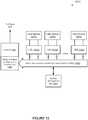
- FIG 13illustrates a photovoltaic system (1200) according to one example.
- the photovoltaic system 1200is built from a few components, including photovoltaic modules (1201a, 1201b, ..., 1201n), local management unit units (1202a, 1202b, ..., 1202n), an inverter (1203), and a system management unit (1204).
- the system management unit (1204)is part of the inverter (1203), the combiner box (1206), a local management unit, or a stand-alone unit.
- the solar modules (1201a, 1201b, ..., 1201n)are connected in parallel to the local management unit units (1202a, 1202b, ..., 1202n) respectively, which are connected in series to form a string bus (1205), which eventually is connected to an inverter (1203) and the system management unit (1204).
- the string bus (1205)can be connected to the inverter (1203) directly or as part of a mesh network or combiner boxes or fuse boxes (not shown).
- An isolated local management unitcan be used as a combiner box (1206) to adjust all voltages before connecting to the inverter (1206); or, a single or multi-string inverter can be used.
- the system management unit (1204)may assign a different phase for each of the local management units (1202a, 1202b, ..., 1202n). In one example, at any given time, a maximum of a predetermined number of solar modules (e.g., one single solar module) are disconnected from the string bus (1205).
- the local management unitscan have the signal inputs, including but not limited to duty cycle (1104a), phase (1104b) and synchronization pulse (1104c) (e.g., to keep the local management units synchronized).
- the phase (1104b) and the synchronization pulse (1104c)are used to further improve performance, but the local management unit (1101) can work without them.
- the local management unitmay provide output signals.
- the local management unit (1101)may measure current and voltage at the module side and optionally measure current and voltage in the string side.
- the local management unit (1101)may provide other suitable signals, including but not limited to measurements of light, temperature (both ambient and module), etc.
- the output signals from the local management unit (1101)are transmitted over the power line (e.g., via power line communication (PLC)), or transmitted wirelessly.
- PLCpower line communication
- the system management unit (1204)receives sensor inputs from light sensor(s), temperature sensor(s), one or more each for ambient, solar module or both, to control the photovoltaic system (1200).
- the signalsmay also include synchronization signals.
- the local management unitcan be a very non-expensive and reliable device that can easily increase the throughput of a photovoltaic solar system by a few (e.g., signal or low double digits) percentage points.
- These varied controlsalso allow installers using this kind of system to control the voe (open circuit voltage) by, for example by shutting off some or all modules.
- a few modulescan be disconnected from a string if a string is getting to the regulatory voltage limit, thus more modules can be installed in a string.
- local management unitscan also be used within the solar panel to control the connection of solar cells attached to strings of cells within the solar panel.
- FIG 14illustrates a solar panel according to one example.
- the solar panel (1300)has a few strings of solar cells (e.g., three solar cell strings per module).
- a local management unit (1101)can be applied to a group of cells (1301) within a string of an individual solar panel (1300), or in some cases to each cell (1301) in a solar panel (1300).
- a group of solar cells (1301) that are attached to a local management unit (1101)may be connected to each other in series, in parallel, or in a mesh configure.
- a number of local management units (1101)connect the groups of the solar cells (1301) in a string to provide output for the solar panel (1300).
- Some examples of the disclosureincludes methods to determine the duty cycles and/or phases for local management units connected to a string or mesh of solar modules.
- the duty cycle of all local management units in a string or meshcan be changed, to increase or decrease the string voltage.
- the duty cyclesmay be adjusted to avoid exceeding the maximum voltage allowed.
- the maximum voltagemay be limited by the combiner box (1206), the inverter (1203), or any other load connected to the string bus (1205), or limited by any regulations applicable to that system.
- the duty cyclesare adjusted to align the voltage of multiple strings.
- the duty cycle of one local management unit (1101) in a stringcan be changed to cause higher current in that local management unit (1101) and overall higher power harvesting.
- the duty cyclesare computed for the solar modules that are connected to a string via the corresponding local management units.
- the duty cyclescan be calculated based on the measured current and voltages of the solar modules and/or the temperatures.
- the duty cyclescan be further fine tuned and/or re-adjusted to changes, such as shifting shading etc., one step at a time, to improve power performance (e.g., to increase power output, to increase voltage, to increase current, etc.).
- target voltagesare computed for the solar modules, and the duty cycles are adjusted to drive the module voltage towards the target voltages.
- the methods to compute the duty cycles of the solar modulescan also be used to compute the duty cycles of the groups of solar cells within a solar module.
- Figures 15 through 17show methods to improve performance of a photovoltaic system according to some examples.
- At least one operating parameter of a solar energy production unit coupled to a string via a management unitis received (1401) and used to identify (1403) a duty cycle for the management unit to connect the solar energy production unit to string.
- the solar energy production unitmay be a solar module, a group of solar cells within a solar module, or a single solar cell in a string in a solar module.
- the duty cycleis adjusted (1405) to optimize the performance of the solar energy production unit and/or the string.
- the duty cyclecan be adjusted to increase the current in the string and/or the solar energy production unit, to increase the output power of the string and/or the solar energy production unit, to increase the voltage of the solar energy production unit, etc.
- the operating voltages of a plurality of solar panels connected in seriesare received (1421) and used to identify (1423) a second solar panel having the highest operating voltage (highest output power) in the string.
- a duty cycle of a first solar panelis computed (1425) based on a ratio in operating voltage between the first and second solar panels.
- the duty cyclecan be computed based on a ratio in output power between the first and second solar panels.
- the duty cyclecan be computed based on a ratio between the first and second solar panels in estimated/computed maximum power point voltage.
- the duty cyclecan be computed based on a ratio between the first and second solar panels in estimated/computed maximum power point power.
- the duty cycle of the first solar panelis adjusted (1427) to improve the performance of the first solar energy production unit and/or the string, until a decrease in the operating voltage of the second solar panel is detected.
- the duty cycle of the first solar panelcan be adjusted to increase the total output power of the string, to increase the current of the string, to increase the current of the first solar panel, to drive the voltage of the first solar panel towards a target voltage, such as its maximum power point voltage estimated based on its current operating parameters, such as temperature or a voltage calculated using its estimated maximum power point voltage.
- the duty cycle of the second solar panelis optionally decreased (1431) to increase the operating voltage of the second solar panel.
- the strongest solar panelor strong panels within a threshold from the strongest panel
- is not switched off linee.g., to have a predetermined duty cycle of 100%.
- the duty cycle of the second solar panelis repeatedly decreased (1429) until it is determined (1431) that the decrease (1429) in the duty cycle of the second solar panel cannot increase the voltage of the second solar panel.
- operating parameters of a plurality of solar panels connected in a stringare received (1441) and used to identify (1443) a first maximum power point voltage of a first solar panel.
- a second solar panel having the highest operating voltage (or output power) in the stringis identified.
- a second maximum power point voltage of the second solar panelis identified (1447) based on the received operating parameters and used to compute (1449) a target voltage for the first solar energy production unit.
- the target voltageis a function of the first and second maximum power point voltages and the highest operating voltage identified (1445) in the second solar panel in the string.
- the duty cycle of the first solar energy production unitis adjusted to drive the operating voltage of the first solar panel towards the target voltage.
- the target voltagemay be the set as the first maximum power point voltage of the first solar panel.
- a same factoris applied to all modules in that string. For example, in a case of a first module Al that is producing only 80%, and the voltage of the whole string needs to be 5% lower, the duty cycle of A 1 is 80% multiplied the duty cycle applied to the whole string (which is Y in this example) so module Al then has Y x 0.8 as duty cycle.
- system management unit (1204) and/or the local management unitsare used solely or in combination to determine the parameters to control the operations of the switches.
- a system management unit (1204)is the "brain" of the system, which decides on the duty cycle and phase parameters.
- each local management unitbroadcasts information to the other local management units on the string to allow the individual local management units to decide their own duty cycle and phase parameters.
- a local management unitmay instruct one or more other local management units to adjust duty cycle and phase parameters.
- the local management units on a string bus (1205)may elect one local management unit to compute the duty cycle and phase parameters for other local management units on the string.
- the system management unit (1204)may determine one or more global parameters (e.g., a global duty cycle, the maximum power on the string, the maximum voltage on the string, etc.), based on which individual local management units adjust their own duty cycles.
- global parameterse.g., a global duty cycle, the maximum power on the string, the maximum voltage on the string, etc.
- a local management unitmay determine its own duty cycles without relying upon communicating with other management units. For example, the local management unit may adjust its duty cycle for connecting its solar module to the string to operate the solar module at the maximum power point.
- module voltageare measured by the local management units in the same string at substantially/approximately the same time and used to identify the strongest solar module.
- a strongest solar moduleprovides the most power in the string. Since the modules are connected in series, the solar module having the highest module voltage in the string can be identified as the strongest solar module.
- the operating voltage and current of the solar moduleare measured to determine the power of the solar module.
- the duty cycle for each modulecan be computed as a function of a ratio between the module voltage V of the module and the highest module voltage Vm.
- the system management (1204)may identify the highest module voltage from the module voltages received from the local management units (1202a, 1202b, ..., 1202n), and compute the duty cycles for the corresponding local management units (1202a, 1202b, ..., 1202n).
- the local management units (1202a, 1202b, ..., 1202n)may report their module voltages on the string bus (1205) to allow individual local management units (1202a, 1202b, ..., 1202n) to identify the highest module voltage and compute the duty cycles, without relying upon the system management unit (1204).
- one of the local management units (1202a, 1202b, ..., 1202n)may identify the highest module voltage and/or compute the duty cycles for the other local management units (1202a, 1202b, ..., 1202n).
- the duty cyclesare determined and/or adjusted periodically.
- the duty cycles for the solar modules on the stringare set based on the module voltage ratio relative to the highest module voltage in the string, the duty cycles can be fine tuned to increase the power performance.
- the duty cyclescan be fine tuned one step at a time, until a decrease of voltage of the module with the highest power is detected. In response to the detected decrease, the last change that caused the decrease can be reversed (undone).
- the fine tuning of the duty cyclescan be used to reach the peak performance point (e.g., for maximum power point tracking).
- the duty cycles of the solar modules on the stringare adjusted until the module with the highest power in the string decrease its voltage. Since decreasing the duty cycle of a solar module decreases the time period the module is connected to the string and thus increases its voltage, the duty cycle of the module with the highest power in the string can be decreased to increase its voltage, in response to the decrease in its voltage caused by the adjustment to the duty cycles of other solar modules on the string. For example, the duty cycle of the module with the highest power in the string can be decreased until its voltage is maximized.
- the local management unitmeasures module and ambient temperatures for some methods to determine the duty cycles.
- the operating parameters measured at the local management unitse.g., 1202a, 1202b, ..., 1202n
- module temperaturecan be used compute the estimated voltages of the solar modules at their maximum power points.
- a formula presented by Nalin K. Gautam and N.D. Kaushika in "An efficient algorithm to simulate the electrical performance of solar photovoltaic arrays", Energy, Volume 27, Issue 4, April 2002, pages 347-261can be used to compute the voltage Vmp of a solar module at the maximum power point.
- Other formulaecan also be used.
- the duty cycle of the solar module connected to a stringcan be adjusted to drive the module voltage to the computed/estimated maximum power point voltage Vmp, since decreasing the duty cycle of a solar module normally increases its voltage.
- a local management unitmay adjust the duty cycle of the solar module connected to the local management unit to change the module voltage to the computed/estimated maximum power point voltage Vmp, without having to communicating with other management units.
- a local management unitmay adjust the duty cycle of the solar module connected to the local management unit to perform maximum power point tracking.
- the duty cycle for each module on a stringcan be computed as a function of a ratio between the maximum power point voltage Vmp of the module and the maximum power point voltage Vmpm of the strongest module.
- the duty cyclecan be periodically updated, based on the current operating parameters measured, and/or fine tuned until a decrease in the voltage of the strongest module is detected.
- a target voltage for each module on the stringcan be computed as a function of a ratio between the maximum power point voltage Vmp of the module and the maximum power point voltage Vmpm of the strongest module.
- the target voltage for a modulecan be computed as Vm x VmpNmpm, where Vm is the measured voltage of the strongest module.
- the duty cycle of the modulecan be changed to drive the module voltage of the module towards the target voltage.
- the duty cycle for each module on a stringcan be computed as a function of a ratio between the maximum power point power Pmp of the module and the maximum power point power Pmpm of the strongest module.
- the duty cyclecan be periodically updated, based on the current operating parameters measured, and/or fine tuned until a decrease in the voltage of the strongest module is detected, since decreasing the duty cycle normally increases the module voltage.
- a target voltage for each module on the stringcan be computed as a function of a ratio between the maximum power point power Pmp of the module and the maximum power point power Pmpm of the strongest module.
- the target voltage for a modulecan be computed as Vm x Pmp/Pmpm, where Vm is the measured voltage of the strongest module.
- the duty cycle of the modulecan be changed to drive the module voltage of the module towards the target voltage, since decreasing the duty cycle normally increases the module voltage.
- the duty cycle for each local management unitis changed to increase the current of the solar module attached to the local management unit (e.g., based on the measurement of the voltage and current of the solar module), until the maximum current is achieved.
- This methodassumes that string maximum power can be achieved with some accuracy by driving each local management unit to maximum current.
- the voltages and currents of the solar modulesare measured for tuning the duty cycles for maximum power point tracking for the string. The measurements of the voltages and currents of the solar modules also enable the local management units to additionally serve as a module level monitoring system.
- the duty cyclescan be adjusted by the system management unit (e.g., 1204) based on the measurements reported by the local management units (e.g., 1202a, 1202b, ..., 1202n), or adjusted directly by the corresponding local management units (e.g., 1202a, 1202b, ..., 1202n).
- the system management unite.g., 1204
- the local management unitse.g., 1202a, 1202b, ..., 1202n
- the corresponding local management unitse.g., 1202a, 1202b, ..., 1202n
- the maximum power point tracking operation by the inverter (1203)is frozen (temporarily stopped).
- Light intensity at the solar modulesis monitored for changes.
- the voltage and current of the solar modulesare measured for the determination of the duty cycles. Then normal operation resumes (e.g., unfreezing of maximum power point tracking operation).
- a predetermined thresholdis used to select the weak modules to apply duty cycles. For example, in one example, when a module produces power less than a predetermine percent of highest power Pm, a duty cycle is calculated and applied to the solar module. If the module is above the threshold, the module is not disconnected (and thus having a duty cycle of 100%).
- the thresholdmay be based on the power, or based on the module voltage.
- the system management unit (1204)finds the duty cycles for the local management units (1202a, 1202b, ..., 1202n) and transmits data and/or signals representing the duty cycles to the local management units (1202a, 1202b, ..., 1202n) via wires or wireless connections.
- the local management units (1202a, 1202b, ..., 1202n)may communicate with each other to obtain the parameters to calculate the duty cycles.
- the system management unit (1204)knows all the different duty cycles indicated for the local management units (1202a, 1202b, ..., 1202n).
- the system management unit (1204)sends the appropriate data/signal to the appropriate local management units (1202a, 1202b, ..., 1202n), and then the system management unit (1204) calculates the total power of the string and corrects the duty cycle to produce maximum power.
- the duty cycles for the local management units (1202a, 1202b, ..., 1202n)may be saved in a database and serve as a starting point for the corresponding local management units (1202a, 1202b, ..., 1202n) at the same time of day on the next day.
- a local managementmay store the duty cycle in its memory for the next day.
- the stored duty cyclescan be used when there is a fixed shade on the modules, such as a chimney, a tree, etc., which will be the same shade on any day at the same time.
- historical datamay not be saved, but may be recalculated from scratch on each run, for example every 30 minutes.
- the light intensity at the solar modulesis monitored for changes.
- the duty cyclesare calculated when the light intensity does not change significantly. If there are changes in sun light radiation at the solar modules, the system will wait until the environment stabilizes before applying or adjusting the duty cycles.
- the system management unit (1204)can communicate with the inverter as well.
- the invertermay stop maximum power point tracking. In such a situation, the inverter can be set up for its load, instead of tracking for maximum power point.
- the system management unit (1204) and the local management units (1202a, 1202b, ..., 1202n)are used to set the operating parameters and balance the string.
- FIG 18shows an overview of an exemplary photovoltaic power system 2100 known to the inventors.
- Photovoltaic solar panel (PVSP) 101typically connects via wires 2103, such pigtail wires, to a junction box 2102, which in tum connects the wiring 2104 to the wiring system, typically as part of a string of panels, or a high voltage box, to a combiner box (essentially a wiring panel) and from there on to an inverter feeding the power grid.
- PVSPphotovoltaic solar panel
- the watch dogis injunction box 2102; in other cases the watch dog may be in other locations in the wiring further down the line, such as, for example, in the combiner box that combines wires of multiple panels and/or strings, or it may be in an inverter box that combines multiple wirings and the inverter.
- Figure 19shows an overview of an exemplary photovoltaic power system 2200 that is known to the inventors. Wires from the panel 2103 feed into converter or adaptor 2203. A controller 2204 is also present, which controller communicates with a central controller 2109 (shown in Figure 10 ) as indicated by arrow 2206, in some cases via a wire line and in other cases wirelessly. Often a diode 2205 may be included for reversal of the panel, or if the panel has weak cells, to avoid reversal of the panel.
- the configuration shown in Figure 19is typical of a string configuration, but similarly it may apply in ac or other similar configurations, or high-voltage bus configurations, all of which are known to the inventors. It is clear that in the case of an ac configuration, diode 2205 would not be included in the system, because it would create serious problems.
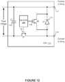
- FIG 20shows an overview of an exemplary system 2300 according to one example of the current invention.
- System 2300is essentially an enhancement of system 2200, wherein the controller 2204 now has additional code 2308, which code performs the shut- down function of the current invention.
- additional code 2308which code performs the shut- down function of the current invention.
- switch 2305is used to short a panel. In this example it is shown as a normally open switch, controlled by controller 2204 (control line not shown).
- the on/off devicecould be typically a suitable semiconductor device, including but not limited to a FET or MOSFET, or it could be an IGBT type of transistor that can take the current and short the panel.
- the on/off devicewould create an active load to the panel and would allow a voltage to continue feed to the controller, as is shown by the feeding line, even though the inverter or converter 2203 may be shut off.
- a switch 2304which is normally closed. Again, rather than a mechanical switch, this could be a FET, MOSFET, or other similar suitable type of semiconductor switch. It is normally closed to allow the power of the inverter to flow out into the wiring; however, it could go into a normal open state and thus disconnect the panel.
- the converter or inverter 2203may achieve the same function internally by managing switching devices already inside a converter accordingly. Also, in some cases, switch 2307 may short the panel bypass.
- a bypassmay be desirable. In other cases, no bypass is desired, or, in the case of a high-voltage system a bypass may even be not desirable.
- the shut-offmay be triggered by, for example, the absence of a regular signal from the main controller (not shown). In other cases, for example, a fault in the wiring, which can be detected by controller 2204 by comparing different voltages, etc., may also automatically trigger a disconnect. In yet other cases, additionally, for example, the plus or the minus may be connected to ground to add security.
- system 2300may have a local capacitor or battery to power the unit even after loss of power from both sides.
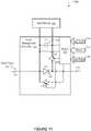
- Figure 21shows an exemplary process 2400 for implementation of the watch dog code 2308 according to one example of the present invention.
- parametersare initialized based on data from a storage 2401 that would typically be an E2PROM in the device itself, and hence it could even survive loss of power.
- the softwareexecutes local checks, which checks may include checking that the wiring, voltages, and other components are correct and all signals present as they should be for normal operation.
- the softwarewaits for a ping from the main controller. In some cases, the software may not wait for an incoming ping, but rather, it may issue a challenge and receive a response to that challenge. Other, similar well known methods of two-way verification may be used.
- the processbranches.
- the softwarereceives a response it moves to operation 2407 to determine whether the response is a shut-down signal. If the response is not a shutdown signal (negative), the software loops back to operation 2403. If the response is a shut- down signal, the software moves to operation 2408, where it shuts down the system and, in operation 2409, waits for a restart signal, after which it returns to operation 2402. If, in operation 2405, the software does not receive a ping or other expected response within an allotted time, it moves to operation 2406, where it checks the number of allowed skips. Depending on the circumstances, a certain number of skips may be allowed, particularly if the "heartbeats" of the ping are set at a high rate, such as 100 or even 1000 per second.
- the softwaremay allow two, five, or even 100 skips (this limit is drawn from data store 2401) before it moves to operation 2410, where the process again branches. If the software receives a response before the limit is reached (-), the process loops back to operation 2407 and continues as described above. If the software receives no response by the time/count the skip limit is reached (+), the process moves to operation 2408 and proceeds as described above. If the device has a battery, as mentioned above, it may remain in shut-down mode until it either receives a restart signal or until the battery runs down, in which case it does a complete shut-down.
- FIG 22shows an exemplary system 3100 according to one aspect of the system and method disclosed herein.
- Solar panels 3110aa-nnare installed in multiple strings.
- the outputs of the stringsare typically joined in combiner box 3108, which then connects to inverter 3101, which in turn connects to power grid 3109.
- additional hardwaresuch as relays or semiconductor switching elements with an additional local controller may be provided, to allow each string to be powered up individually, thus reducing energy and power needed to poll panels or their respective local units.
- This exampleshows, for reasons of simplicity and clarity, only a single-phase power grid, but the power grid could be a much larger and more complex multi-phase power grid.
- MMUmaster management unit
- auxiliary power supply 3103which connects directly to the power grid and which can, via feed route 3105, provide energy into MMU 3102.
- MMU 3102connects via lines 3107 to the dc wiring system and can, therefore, feed back dc current to the solar panel array, via the combiner box(es) 3108 (only one shown) to the panels and their respective LMUs.
- an auxiliary power supplymay connect directly to the dc wiring between combiner box 3108 and inverter 3101.
- Wiring 3106allows the MMU 3102 to interact with the inverter 3108 and, for example, suppress false starts of the inverter on the auxiliary voltage.
- MMU 3102 or some other, similarly suitable controllermay, for example, turn on only the dc voltage every two or three minutes for a few seconds, thus sending just enough current to wake up the LMUs 3111aa through 3111nn in the panels and allow them to do a quick query, each of their respective panels. Then if, for example, two minutes later, one of the units does not respond to the query, the system would send an alarm indicating a possible security breach, such as a wire being cut or a panel being removed. In some cases, before sending an alarm, a re-test may be done, to verify that the alarm is caused by a non-responding panel, rather than just a temporary problem polling a unit.
- information server 3121which may belong to an operator of multiple sites with information directed to control specific sites. Additional servers 3140a through 3140n could be, for example, emergency servers of a public agency relevant to the location of the system, USGS earthquake monitors (relevant cases), etc. In some cases, information server 3121 may download information from these servers and then prepare it by location and send a signal to MMU 3102 via a network 3104. In other cases, the MMU 3102 may pull that information directly from those servers. Controller 3130 controls multiple sensors 3131a-n, which could be, for example, smoke sensors, fire sensors, flow sensors, or other practical emergency sensors.
- Figure 23shows a process 3200 implemented by a software instance residing in MMU 3102, according to the system and method of the claimed invention.
- the programchecks the operating status of the MMU 3102.
- the processbranches. If the unit is in standby operating mode (yes), the process moves to operation 3203, where it ends. If the unit is not in standby mode (no), the process moves to operation 3204, where the program queries information server 3121 for applicable local information regarding possible events that warrant a shutdown or other control changes.
- the programqueries emergency servers 3140a-n, and in operation 3206 it queries controller 3130 for input from sensors 3131a-n. In some cases the sensors may be connected directly to the MMU 3102 through additional ports.
- MMU 3102may connect to an existing fire alarm system controller, and pulling the fire alarm could also shut off power generation, for example, either for all or for part of a system.
- the programchecks, based on some pre-existing values and rules, including, for example, location, ZIP code, and other information, whether any of the query results indicate a shut down anywhere in or in all the solar array. If no, the process moves to operation 3203, where the program ends. If yes, the process moves to operation 3208, where the program sends out commands to the indicated units, which commands could shut down or disconnect the inverter 3101.
- an additional galvanic disconnectis provided outside the inverter.
- the programalso instructs the LMUs to shut down, or in other cases the local power remains available but an additional disconnect shuts off the remote aspect.
- different actionsmay be taken. For example, if a local fire is indicated, some or all the panels in the affected area may be turned off as a safety measure for responding firefighters, but the remainder of the system may be left working.
- a galvanic disconnectmay shut off the connection to the power grid 40-109, but, for example only if a sensor (not shown) determines that the supply line has been broken (i.e., no safe connection).
Landscapes
- Physics & Mathematics (AREA)
- General Physics & Mathematics (AREA)
- Engineering & Computer Science (AREA)
- Power Engineering (AREA)
- Photovoltaic Devices (AREA)
- Life Sciences & Earth Sciences (AREA)
- Sustainable Development (AREA)
- Sustainable Energy (AREA)
- Supply And Distribution Of Alternating Current (AREA)
Description
- A portion of the disclosure of this patent document contains material which is subject to copyright protection. The copyright owner has no objection to the facsimile reproduction by anyone of the patent document or the patent disclosure, as it appears in the patent and trademark office patent file or records, but otherwise reserves all copyright rights whatsoever.
- The present invention relates to the field of electrical safeguards for photovoltaic systems.
- When a photovoltaic panel or laminate is exposed to direct or diffuse light, a lethal voltage potential may be present. In the United States the possible voltage could be as high as 600 volts, while in Europe and the rest of the world this voltage could approach a kilovolt.
- Because of this potential danger from electrical shock, solar panel manufacturers and code and standards development organizations have made some recommendations to minimize or eliminate this danger.
- One suggestion has been to cover the photovoltaic panel with an opaque material such as a tarpaulin. However, this approach proposes its own safety risk from having the wind catch the tarpaulin and pull installation personnel off the roof as they try to control the unstable sheet material against the wind.
- Another recommendation is to install and/or service the photovoltaic panels at night when there is minimal risk of the panels being energized. This approach presents the potential safety risks associated from working in a poorly lighted environment.
- In addition to the potential personnel safety issues there are also significant risks to equipment and hardware. Connecting or disconnecting energized plugs can cause arcing and damage to these connectors, junction boxes, and other electrical components.
- Solar system installers take a large guard band (or safety margin) to make sure the voltages don't cross the 600V or 1000V limits in the United States and the European Union, respectively. That limitation inhibits them from installing more solar panel modules, often referred to as "modules" or "panels," in series to reduce the cost of combiner boxes or string inverters. When solar modules are connected in series or in mesh configurations, there can be a problem in which weaker modules not only produce less energy but also affect other modules' capabilities to deliver energy in the same string or wiring section.
- In solar panel installations it is often desirable to have additional safety for the operating environment and for personnel involved with maintenance, etc. Of particular concern are certain portions of the wiring. If certain wires are disconnected, through theft, vandalism, accident, natural forces, or any other cause, voltages may rise to an unacceptable, even dangerous, level.
- In addition to locally generated problems that can affect the safety of the system and or people working at or near the system, other, more regionally created problems may cause safety issues, including, for example, floods, forest fires or neighborhood fires, earthquakes, landslides, etc.
- Patent application
WO2009/006879 describes a photovoltaic system having a plurality of photovoltaic elements electrically connected to one another and electrical lines for providing electrical current. Patent application DE 10 2005 018173 (A1 ) describes a method involving attaching a switching device in direct proximity to a generator field within or outside a structure. The field is shortcircuited by a control line which is activated manually or automatically. The field stands in a safe operating point in which energy transfer in the structure is not allowed. The device switches the field on demand into the low-energy operating point by the control line.Patent application DE 10 2008 003272 (A1 ) describes a monitoring unit which has a function monitoring system, and a conversion module directly converting radiation energy i.e. solar energy, into electric energy. The monitoring unit is centrally monitored and recorded from a controlling computer, where the monitoring unit is arranged at a set of photovoltaic modules (1-3). A set of function modules is arranged at each of the photovoltaic modules, so that the function modules are interchanged during the interchange of the photovoltaic modules and are arranged in connection boxes (4-6).- Patent application
US 2010/071274 describesa unitized curtain wall unit which is adapted to incorporate power generating elements within an exterior shell or façade of a building structure. The units can also be adapted to house other power generating system components-including control units and associated power/signal wiring. - The present invention is as set out in the appended claims.
- According to an aspect of the present invention, there is provided a system according to
claim 1. - According to another aspect of the present invention, there is provided a method according to claim 2.
- These and other objects and advantages of the present invention will become clear to those skilled in the art in view of the description of the best presently known mode of carrying out the invention and the industrial applicability of the preferred embodiment as described herein.
Figure 1 illustrates a solar panel having a safety switch according to one exampleFigures 2-5 illustrate a spring loaded safety switch for a photovoltaic panel according to one example.Figures 6-7 illustrate a junction box with a reed switch for a photovoltaic panel according to one example.Figure 8 illustrates an optical sensor to control a safety switch for a photovoltaic panel according to one exampleFigure 9 illustrates a solar panel having a safety switch controlled via auxiliary wiring according to one example.Figures 10-12 illustrate local management units according to some examples.Figure 13 illustrates a photovoltaic system according to one example.Figure 14 illustrates a solar panel according to one example.Figures 15-17 show methods to improve performance of a photovoltaic system according to some examples.Figure 18 illustrates an example of an energy production system including a plurality of junction boxes each coupled between a solar module and a power bus.Figure 19 illustrates a solar module and a detail view of an example of a junction box.Figure 20 illustrates an example of a junction box.Figure 21 illustrates an example of a method of controlling the output of a solar module.Figure 22 illustrates an example of an energy production system including a master management unit.Figure 23 shows an embodiment of a process residing a master management unit controlling the output of a solar module.- The following description and drawings are illustrative and are not to be construed as limiting. Numerous specific details are described to provide a thorough understanding. However, in certain instances, well known or conventional details are not described in order to avoid obscuring the description. References to one or an embodiment in the present disclosure are not necessarily references to the same embodiment; and, such references mean at least one.
- The use of headings herein are merely provided for ease of reference, and shall not be interpreted in any way to limit this disclosure or the following claims.
- Reference in this specification to "one embodiment" or "an embodiment" means that a particular feature, structure, or characteristic described in connection with the embodiment is included in at least one embodiment of the disclosure. The appearances of the phrase "in one embodiment" in various places in the specification are not necessarily all referring to the same embodiment, nor are separate or alternative embodiments mutually exclusive of other embodiments. Moreover, various features are described which may be exhibited by some embodiments and not by others. Similarly, various requirements are described which may be requirements for some embodiments but not other embodiments.
- One example of the disclosure provides a method and system to reduce the safety risks during the shipment, installation and/or maintenance of photovoltaic systems, without introducing the risks associated with other approaches, such as covering them with an opaque material or working on them at night.
- In one example, safety protection is provided via the inclusion of a normally closed switch integral to the panel junction box or integral to the panel module when alternating current (AC) or direct current (DC) modules are used.
Figure 1 illustrates a solar panel having a safety switch according to one example. InFigure 1 , a solar panel 10 (e.g., a photovoltaic panel) includes at least one solar cell 12 (e.g., a photovoltaic cell) to generate power when exposed to direct or diffuse light, in some cases avoltage module 14 to adjust or regulate the output voltage (or in some other cases a current module to regulate current), and aswitch 16 to selectively isolate thesolar cell 12 from the output connectors of the solar panel. In yet other cases, the switch may be incorporated into regulator modules, such asvoltage module 14.- In one example, the
switch 16 is a normally closed switch. During the shipment, installation and/or maintenance, theswitch 16 is placed in an open state to isolate thesolar cell 12 from the output. After the installation or maintenance, theswitch 16 is placed into a closed state to allow thesolar cell 12 to energize the output connectors of the solar panel and to supply power through the output connectors of the solar panel. - The
switch 16 and the voltage module can be integrated into the junction box of the solar panel. In some example, theswitch 16 is integrated with thevoltage module 14 as a panel module. Figures 2 through 5 illustrate a spring loaded safety switch for a photovoltaic panel according to one example. InFigures 2 through 5 , the switch includes twocontactors contactors contactors contacts contactors - In
Figure 2 , a safe mode for installation or maintenance is achieved when theblade 104 is inserted between the twocontactors blade 104 is manufactured from a dielectric material and when inserted between the twocontactors contactors - As illustrated in
Figure 2 , theblade 104 may also have aflag 105 attached. Theflag 105 could be red or some other highly visible color, to provide a visual indicator of the state of the panel. - In one example, the panels and/or panel with integral modules would come shipped from the factory with the
blade 104 and theflag 105, where theblade 104 is inserted between the twocontactors blade 104 present andflag 105 visible. The installer would mount, secure, and plug in all of the connections in the system, including the grounding. - As illustrated in
Figure 3 , once the installation is completed the installer would remove theblades 104 at all those places indicated by theflags 105. Once theblade 104 is removed, the spring loadedcontactors - If additional work or troubleshooting were needed, the blade(s) 104 and flag(s) 105 could be reinserted, aided by the tapered
section 207 of theblade 104, thereby breaking the electrical continuity between thecontactors point 206. - In some examples, there is symmetry in
contactors contactors contactors conductive path 206 is maintained, after theblade 104 is removed. In at least some examples, the electricalconductive path 206 is maintained without theblade 104 being inserted between thecontactors blade 104 inserted between thecontactors blade 104. - In addition to the visual indication of the modes of the panels provided by the flag(s) 105, the flags could also provide information in the form of text, such as, for example, "Remove before operation" or a warning of potentially lethal voltage.
Figure 4 illustrates a configuration of a spring loaded switch integrated with ajunction box 308 of a photovoltaic panel. Thejunction box 308 includes a connector to connect the solar power generated by the photovoltaic panel to a load (e.g., an inverter, a voltage bus, etc.) via acable 307. Thus, when theblade 104 is inserted into the switch, with theflag 105 visible, the voltage generated by the solar cells is isolated from the connector for thecable 307; and thus it is safe to install the photovoltaic panel or to perform maintenance operations on the photovoltaic panel.Figure 5 shows the components of the spring loaded switch and the junction box of a photovoltaic panel. As illustrated inFigure 5 , thejunction box 308 has anopening 409, which provides access to remove theblade 104 and/or to re-insert theblade 104. Thecontactors 103 of the switch can be attached to thejunction box 308 via fastening theportion 401 to a supporting member of thejunction box 308, such as a printed circuit board (PCB).Figures 6 through 7 illustrate a junction box with a reed switch for a photovoltaic panel according to one example.Figure 6 shows an assembly of areed switch 510 and magnets for integrated into thephotovoltaic junction box 308.Figure 7 shows a cut-away section illustrating thereed switch 510 and themagnets portion 509 of thejunction box 308.- In
Figure 7 , areed switch 510 is made normally closed by integrating astationary biasing magnet 511 into thejunction box 308 in close proximity to the normally open reed switch, so that theswitch 510 is closed in absence of themagnet 512. - In one example, the
magnet 512 is inserted into the junction box well 509 so that the reversed polarity cancels the magnetic lines of force and thereed switch 510 opens. - In one example, the
magnet 512 is installed in the junction box well 509 at the factory; and a flag 105 (not shown inFigures 6 and 7 ) is attached to themagnet 512. Themagnet 512 is removable and/or re-insertable via the junction box well 509. - In other examples, normally closed (NC) reed contacts can be used to replace the normally open (NO)
reed contacts 510 and themagnet 511, avoiding the need for the additional stationary magnet. - Once the installation and integrations are complete the
magnet 512 is removed and may be discarded. The power leads of thejunction box 308 can then be energized via the semiconductor switch or relay (not shown), when thereed switch 512 is in the closed state. - In some cases, a semiconductor switch (not shown in
Figure 7 ) can be used to energize the power leads of thejunction box 308. Thepanel junction box 308 or inverter (not shown inFigure 7 ) may include a controller unit with a watch dog circuit configured to send a signal periodically (e.g., every time interval t) to maintain the connection of the panel outputs to the string. When this signal is timed-out or is absent, the panel outputs of the panel are disconnected via a semiconductor switch device (not shown). Figure 8 illustrates an optical sensor to control a safety switch for a photovoltaic panel according to one example. InFigure 8 , anoptical sensor unit 700 with anoptical sensor 701 is mounted on a printed circuit board (PCB) 711. Additionally, springs 702 and 712 hold aseparator 703 in place that can be removed in direction ofarrow 704 using a pull-tab similar to theflag 105 discussed earlier. Not shown inFigure 8 is the exterior enclosure that would contain the mechanical elements such as the cable connections and the guide elements for guidingseparator 703 in and out of the unit.- In one example, additional circuitry (not shown in
Figure 8 ) will be on the side of thePCB 711, such as a control circuit to affect an on/off switching either in some cases by FET (Field-Effect Transistor) transistors or using, in other cases, a relay, such as a bi-stable relay or another suitable circuit. The operational power may be drawn from the solar system itself, or it may be brought up by auxiliary wiring. - In yet some other examples, a relay can be simply remote controlled by an auxiliary wire to close or open the circuit. The advantage of this approach is that no pull-tabs (flags or blades) can be forgotten on the roof.
- In one example, a mechanism and/or circuitry is integrated in the panel to identify the load from the inverter and connect the panel to the panel outputs when the load is detected. When no load is present the panel outputs is disconnected. This functionality would also be implemented using a semiconductor switch device or other suitable device (such as a relay), and some sensor circuitry, allowing an automatic reconnect when the loop appears to be closed and a load connected.
Figure 9 illustrates a solar panel having a safety switch controlled via auxiliary wiring according to one example. InFigure 9 , a separate wire is connected to control theswitch 16 from a remote location. For example, the switch may be controlled via a signal from a watch dog circuit, from a remote switch or controller, etc.- When solar modules are connected in series or mesh configuration, there can be a problem in which weaker modules not only produce less energy but also affect other modules in the same string or wiring section. By measuring one can determine that a few modules are weaker than the others in most commercially installed strings. Thus, the string is generating less power than the sum available at each module if modules were operated separately.
- At least one example of the present disclosure provides methods and systems to switch on and off weak modules in the string in a way that the current on the string bus from the good modules won't be affected by the weak modules.
Figures 10 through 12 illustrate local management units according to some examples. InFigures 10 through 12 , local management units (1101) are used to switch on and off the solar module (1102) periodically to improve the energy production performance of the photovoltaic systems connected, at least in part, in series.- In
Figure 10 , a management unit (101) is local to the solar module (102) and can be used to periodically couple the solar module (102) to the serial power bus (103) via the switch Q 1 (106), to improve the total power output for the string of solar modules connected to the serial power bus in series. - The local management unit (LMU) (1101) may include a solar module controller to control the operation of the solar module (1102) and/or a link module unit to provide connectivity to the serial power bus (1103) for energy delivery and/or for data communications.
- In one example, the command to control the operation of the switch QI (1106) is sent to the local management unit (1101) over the photovoltaic (PV) string bus (power line) (1103). Alternatively, separate network connections can be used to transmit the data and/or commands to/from the local management unit (1101).
- In
Figures 10 and11 , the inputs (1104a, 1104b, 1104c) to the local management unit (1101) are illustrated separately. However, the inputs (1104a, 1104b, 1104c) are not necessarily communicated to local management unit (1101) via separate connections. In one example, the inputs are received in the local management unit via the serial power bus (1103). - In
Figure 10 , the solar module (1102) is connected in parallel to the capacitor C1 (1105) of the local management unit (1101). The diode DI (1107) of the local management unit (1101) is connected in series in the serial power bus (1103) which may or may not be part of an overall mesh configuration of solar modules. The switch Q1 (1106) of the local management unit can selectively connect or disconnect the solar module (102) and the capacitor C 1 (1105) from a parallel connection with the diode D 1 (1107) and thus connect or disconnect the solar module (1102) from the serial power bus (1103). - In
Figure 10 , a controller (1109) of the local management unit (1101) controls the operation of the switch (1106) according to the parameters, such as duty cycle (1104a), phase (1104b) and synchronization pulse (1104c). - In one example, the controller (1109) receives the parameters (1104a, 1104b, 1104c) from a remote management unit via the serial power bus (1103) or a separate data communication connection (e.g., a separate data bus or a wireless connection). In some example, the controller (1109) may communicate with other local management units connected on the serial power bus (1103) to obtain operating parameters of the solar modules attached to the serial power bus (1103) and thus compute the parameters (e.g., 1104a and 1104b) based on the received operating parameters. In some examples, the controller (1109) may determine the parameter (e.g., 104a and 104b) based on the operating parameters of the solar module (1102) and/or measurements obtained by the controller (1109), without communicating with other local management units of other solar modules, or a remote system management unit.
- In
Figure 11 , a system (100) has a local management unit (1101) coupled to the solar module (1102). The local management unit (1101) is connected between the solar module (1102) and the string bus (1103) to improve the total power output for the whole string on the serial power bus (1103). Commands to the local management unit (1101) can be sent over the photovoltaic (PV) string bus (power line) (1103). To make the figure clearer, the inputs (1104a, 1104b, 1104c) to the controller (1109) of the local management unit (1101) are drawn separately, which does not necessarily indicate that the inputs (1104a, 1104b, 1104c) are provided via separate connections and/or from outside the local management unit (1101). For example, in some examples, the controller (1109) may compute the parameters (1104a, 1104b, 1104c) based on measurements obtained at the local management unit (1101), with or without data communications over the serial power bus (1103) (or a separate data communication connection with other management units). - In
Figure 11 , the local management unit (1101) is connected in one side to the solar module (1102) in parallel and on the other side in series to a string of other modules, which may or may not be part of an overall mesh configuration. The local management unit (1101) may receive, among others, three inputs or types of input data, including a) requested duty cycle (1104a), which can be expressed as a percentage (e.g., from 0 to 100%) of time the solar module (1102) is to be connected to the serial power bus (1103) via the switch Q1 (1106), b) a phase shift (1104b) in degrees (e.g., from 0 degree to 180 degree) and c) a timing or synchronization pulse (1104c). These inputs (e.g., 1104a, 1104b and 1104c) can be supplied as discrete signals, or can be supplied as data on a network, or composite signals sent through the power lines or wirelessly, and in yet other cases, as a combination of any of these input types. - In
Figure 11 , the local management unit (1101) periodically connects and disconnects the solar module (1102) to and from the string that forms the serial power bus (1103). The duty cycle (1104a) and the phase (1104b) of the operation of the switch QI (1106) can be computed in a number of ways to improve the performance of the system, which will be discussed further below. - In
Figure 11 , the local management unit (1101) includes a capacitor C1 (1105) and a switch Q1 (1106), as well as a diode D1 (1107). InFigure 11 , the diode D1 (1107) is supplemented with an additional switch Q2 (1108), which acts as a synchronous rectifier to increase efficiency. In one example, the additional switch Q2 (1108) is open (turned off) when the switch QI (1106) is closed (turned on) to attach the solar module (1102) (and the capacitor C1 (1105)) to the serial power bus (1103). - In some cases, a filter (not shown), including a serial coil and a parallel capacitor, is also used. The filter may be placed at the local management unit or placed just before the fuse box or inverter, or be part of either one of those.
- In
Figure 11 , the controller (1109) is used to process the input signals (e.g., 1104a, 1104b, 1104c) and drive the switches QI (1106) and Q2 (1108). In one example, the controller (1109) is a small single chip micro controller (SCMC). For example, the controller (1109) may be implemented using Application-Specific Integrated Circuit (ASIC) or Field- Programmable Gate Array (FPGA). The controller (1109) can even be implemented in discrete, functionally equivalent circuitry, or in other cases a combination of SCMC and discrete circuitry. - In one example, the controller (1109) is coupled to the solar module (1102) in parallel to obtain power for processing; and the controller (1109) is coupled to the serial power bus (1103) to obtain signals transmitted from other management units coupled to the serial power bus (1103).
- By switching the module (1102) (or groups of cells, or a cell) on and off to the string periodically, the local management unit (1101) may lower the voltage reflected to the string bus (1103) (e.g., a lower average voltage contributed to the string bus) and can cause the current reflected to the string bus (1103) to be higher, nearer the level it would be if the module was not weak, generating a higher total power output.
- In one example, it is preferable to use different phases to operate the switches in different local management units on a string to minimize voltage variance on the string.
- In
Figure 12 , the local management unit (1101) provides two connectors (1112 and 1114) for serial connections with other local management unit (1101) to form a serial power bus (1103) (Figure 11 ). The controller (1109) controls the states of the switches QI (1106) and Q2 (1108). - In
Figure 12 , when the controller (1109) turns on the switch (1106), the panel voltage and the capacitor C1 (1105) are connected in parallel to the connectors (1112 and 1114). The output voltage between the connectors (1112 and 1114) is substantially the same as the output panel voltage. - In
Figure 12 , during the period the switch (1106) is turned off (open), the controller (1109) turns on (closes) the switch (1108) to provide a path around the diode DI (1107) to improve efficiency. - In
Figure 12 , when the switch (1106) is turned off (open), the panel voltage charges the capacitor C1 (1105), such that when the switch (1106) is turned on, both the solar panel and the capacitor (1105) provides currents going through the connectors (1112 and 1114), allowing a current larger than the current of the solar panel to flow in the string (the serial power bus (1103)). When the switch (1106) is turned off (open), the diode D1 (1107) also provides a path between the connectors (1112 and 1114) to sustain the current in the string, even if the switch (1108) is off for some reasons. - In one example, the controller (1109) is connected (not shown in
Figure 12 ) to the panel voltage to obtain the power for controlling the switches QI (1106) and Q2 (1108). In one example, the controller (1109) is further connected (not shown inFigure 12 ) to at least one of the connectors to transmit and/or receive information from the string. In one example, the controller (1109) includes sensors (not shown inFigure 12 ) to measure operating parameters of the solar panel, such as panel voltage, panel current, temperature, light intensity, etc. Figure 13 illustrates a photovoltaic system (1200) according to one example. InFigure 13 , thephotovoltaic system 1200 is built from a few components, including photovoltaic modules (1201a, 1201b, ..., 1201n), local management unit units (1202a, 1202b, ..., 1202n), an inverter (1203), and a system management unit (1204).- In one example, the system management unit (1204) is part of the inverter (1203), the combiner box (1206), a local management unit, or a stand-alone unit. The solar modules (1201a, 1201b, ..., 1201n) are connected in parallel to the local management unit units (1202a, 1202b, ..., 1202n) respectively, which are connected in series to form a string bus (1205), which eventually is connected to an inverter (1203) and the system management unit (1204).
- In
Figure 13 , the string bus (1205) can be connected to the inverter (1203) directly or as part of a mesh network or combiner boxes or fuse boxes (not shown). An isolated local management unit can be used as a combiner box (1206) to adjust all voltages before connecting to the inverter (1206); or, a single or multi-string inverter can be used. To limit the changes in the voltage of the bus, the system management unit (1204) may assign a different phase for each of the local management units (1202a, 1202b, ..., 1202n). In one example, at any given time, a maximum of a predetermined number of solar modules (e.g., one single solar module) are disconnected from the string bus (1205). - In one example, beyond the module connection the local management units can have the signal inputs, including but not limited to duty cycle (1104a), phase (1104b) and synchronization pulse (1104c) (e.g., to keep the local management units synchronized). In one example, the phase (1104b) and the synchronization pulse (1104c) are used to further improve performance, but the local management unit (1101) can work without them.
- In one example, the local management unit may provide output signals. For example, the local management unit (1101) may measure current and voltage at the module side and optionally measure current and voltage in the string side. The local management unit (1101) may provide other suitable signals, including but not limited to measurements of light, temperature (both ambient and module), etc.
- In one example, the output signals from the local management unit (1101) are transmitted over the power line (e.g., via power line communication (PLC)), or transmitted wirelessly.
- In one example, the system management unit (1204) receives sensor inputs from light sensor(s), temperature sensor(s), one or more each for ambient, solar module or both, to control the photovoltaic system (1200). In one example, the signals may also include synchronization signals. For example, a using the described methods the local management unit can be a very non-expensive and reliable device that can easily increase the throughput of a photovoltaic solar system by a few (e.g., signal or low double digits) percentage points. These varied controls also allow installers using this kind of system to control the voe (open circuit voltage) by, for example by shutting off some or all modules. For example, by using the local management units of the system, a few modules can be disconnected from a string if a string is getting to the regulatory voltage limit, thus more modules can be installed in a string.
- In some examples, local management units can also be used within the solar panel to control the connection of solar cells attached to strings of cells within the solar panel.
Figure 14 illustrates a solar panel according to one example. In one example, the solar panel (1300) has a few strings of solar cells (e.g., three solar cell strings per module). InFigure 14 , a local management unit (1101) can be applied to a group of cells (1301) within a string of an individual solar panel (1300), or in some cases to each cell (1301) in a solar panel (1300).- In
Figure 14 , a group of solar cells (1301) that are attached to a local management unit (1101) may be connected to each other in series, in parallel, or in a mesh configure. A number of local management units (1101) connect the groups of the solar cells (1301) in a string to provide output for the solar panel (1300). - Some examples of the disclosure includes methods to determine the duty cycles and/or phases for local management units connected to a string or mesh of solar modules.
- In some examples, the duty cycle of all local management units in a string or mesh can be changed, to increase or decrease the string voltage. The duty cycles may be adjusted to avoid exceeding the maximum voltage allowed. For example, the maximum voltage may be limited by the combiner box (1206), the inverter (1203), or any other load connected to the string bus (1205), or limited by any regulations applicable to that system. In some examples, the duty cycles are adjusted to align the voltage of multiple strings.
- In some examples, the duty cycle of one local management unit (1101) in a string can be changed to cause higher current in that local management unit (1101) and overall higher power harvesting.
- In one example, the duty cycles are computed for the solar modules that are connected to a string via the corresponding local management units. The duty cycles can be calculated based on the measured current and voltages of the solar modules and/or the temperatures.
- After an initial set of duty cycles is applied to the solar modules, the duty cycles can be further fine tuned and/or re-adjusted to changes, such as shifting shading etc., one step at a time, to improve power performance (e.g., to increase power output, to increase voltage, to increase current, etc.). In one example, target voltages are computed for the solar modules, and the duty cycles are adjusted to drive the module voltage towards the target voltages.
- The methods to compute the duty cycles of the solar modules can also be used to compute the duty cycles of the groups of solar cells within a solar module.
Figures 15 through 17 show methods to improve performance of a photovoltaic system according to some examples.- In
Figure 15 , at least one operating parameter of a solar energy production unit coupled to a string via a management unit is received (1401) and used to identify (1403) a duty cycle for the management unit to connect the solar energy production unit to string. The solar energy production unit may be a solar module, a group of solar cells within a solar module, or a single solar cell in a string in a solar module. The duty cycle is adjusted (1405) to optimize the performance of the solar energy production unit and/or the string. - For example, the duty cycle can be adjusted to increase the current in the string and/or the solar energy production unit, to increase the output power of the string and/or the solar energy production unit, to increase the voltage of the solar energy production unit, etc.
- In
Figure 16 , the operating voltages of a plurality of solar panels connected in series are received (1421) and used to identify (1423) a second solar panel having the highest operating voltage (highest output power) in the string. - In
Figure 16 , a duty cycle of a first solar panel is computed (1425) based on a ratio in operating voltage between the first and second solar panels. Alternatively, the duty cycle can be computed based on a ratio in output power between the first and second solar panels. Alternatively, the duty cycle can be computed based on a ratio between the first and second solar panels in estimated/computed maximum power point voltage. Alternatively, the duty cycle can be computed based on a ratio between the first and second solar panels in estimated/computed maximum power point power. - The duty cycle of the first solar panel is adjusted (1427) to improve the performance of the first solar energy production unit and/or the string, until a decrease in the operating voltage of the second solar panel is detected. For example, the duty cycle of the first solar panel can be adjusted to increase the total output power of the string, to increase the current of the string, to increase the current of the first solar panel, to drive the voltage of the first solar panel towards a target voltage, such as its maximum power point voltage estimated based on its current operating parameters, such as temperature or a voltage calculated using its estimated maximum power point voltage.
- In
Figure 16 , in response to the detected decrease in the operating voltage of the second solar panel which had the highest operating voltage, the adjustment in the duty cycle of the first solar panel that causes the decrease is undone/reversed (1429). - In
Figure 16 , the duty cycle of the second solar panel is optionally decreased (1431) to increase the operating voltage of the second solar panel. In some examples, the strongest solar panel (or strong panels within a threshold from the strongest panel) is not switched off line (e.g., to have a predetermined duty cycle of 100%). - In one example, the duty cycle of the second solar panel is repeatedly decreased (1429) until it is determined (1431) that the decrease (1429) in the duty cycle of the second solar panel cannot increase the voltage of the second solar panel.
- In
Figure 17 , operating parameters of a plurality of solar panels connected in a string are received (1441) and used to identify (1443) a first maximum power point voltage of a first solar panel. A second solar panel having the highest operating voltage (or output power) in the string is identified. A second maximum power point voltage of the second solar panel is identified (1447) based on the received operating parameters and used to compute (1449) a target voltage for the first solar energy production unit. In one example, the target voltage is a function of the first and second maximum power point voltages and the highest operating voltage identified (1445) in the second solar panel in the string. The duty cycle of the first solar energy production unit is adjusted to drive the operating voltage of the first solar panel towards the target voltage. - Alternatively, the target voltage may be the set as the first maximum power point voltage of the first solar panel.
- In one example, to adjust voltage a same factor is applied to all modules in that string. For example, in a case of a first module Al that is producing only 80%, and the voltage of the whole string needs to be 5% lower, the duty cycle of
A 1 is 80% multiplied the duty cycle applied to the whole string (which is Y in this example) so module Al then has Y x 0.8 as duty cycle. - In some examples, the system management unit (1204) and/or the local management units (e.g., 1202a, 1202b, ..., 1202n) are used solely or in combination to determine the parameters to control the operations of the switches.
- For example, in one example, a system management unit (1204) is the "brain" of the system, which decides on the duty cycle and phase parameters.
- For example, in another example, each local management unit broadcasts information to the other local management units on the string to allow the individual local management units to decide their own duty cycle and phase parameters.
- In some example, a local management unit may instruct one or more other local management units to adjust duty cycle and phase parameters. For example, the local management units on a string bus (1205) may elect one local management unit to compute the duty cycle and phase parameters for other local management units on the string.
- For example, in some example, the system management unit (1204) may determine one or more global parameters (e.g., a global duty cycle, the maximum power on the string, the maximum voltage on the string, etc.), based on which individual local management units adjust their own duty cycles.
- In some examples, a local management unit may determine its own duty cycles without relying upon communicating with other management units. For example, the local management unit may adjust its duty cycle for connecting its solar module to the string to operate the solar module at the maximum power point.
- In one example, module voltage are measured by the local management units in the same string at substantially/approximately the same time and used to identify the strongest solar module. A strongest solar module provides the most power in the string. Since the modules are connected in series, the solar module having the highest module voltage in the string can be identified as the strongest solar module. In some example, the operating voltage and current of the solar module are measured to determine the power of the solar module.
- In one example, after the highest module voltage Vm in the string is identified, the duty cycle for each module can be computed as a function of a ratio between the module voltage V of the module and the highest module voltage Vm. For example, the duty cycle for a module can be computed as 1 - ((Vm - V)Nm) = VNm.
- In one example, the system management (1204) may identify the highest module voltage from the module voltages received from the local management units (1202a, 1202b, ..., 1202n), and compute the duty cycles for the corresponding local management units (1202a, 1202b, ..., 1202n).
- In one example, the local management units (1202a, 1202b, ..., 1202n) may report their module voltages on the string bus (1205) to allow individual local management units (1202a, 1202b, ..., 1202n) to identify the highest module voltage and compute the duty cycles, without relying upon the system management unit (1204).
- In one example, one of the local management units (1202a, 1202b, ..., 1202n) may identify the highest module voltage and/or compute the duty cycles for the other local management units (1202a, 1202b, ..., 1202n).
- In one example, the duty cycles are determined and/or adjusted periodically.
- In one example, after the duty cycles for the solar modules on the string are set based on the module voltage ratio relative to the highest module voltage in the string, the duty cycles can be fine tuned to increase the power performance. The duty cycles can be fine tuned one step at a time, until a decrease of voltage of the module with the highest power is detected. In response to the detected decrease, the last change that caused the decrease can be reversed (undone). The fine tuning of the duty cycles can be used to reach the peak performance point (e.g., for maximum power point tracking).
- In one example, after the strongest module is identified, the duty cycles of the solar modules on the string are adjusted until the module with the highest power in the string decrease its voltage. Since decreasing the duty cycle of a solar module decreases the time period the module is connected to the string and thus increases its voltage, the duty cycle of the module with the highest power in the string can be decreased to increase its voltage, in response to the decrease in its voltage caused by the adjustment to the duty cycles of other solar modules on the string. For example, the duty cycle of the module with the highest power in the string can be decreased until its voltage is maximized.
- In one example, the local management unit measures module and ambient temperatures for some methods to determine the duty cycles. For example, the operating parameters measured at the local management units (e.g., 1202a, 1202b, ..., 1202n), such as module temperature, can be used compute the estimated voltages of the solar modules at their maximum power points. For example, a formula presented byNalin K. Gautam and N.D. Kaushika in "An efficient algorithm to simulate the electrical performance of solar photovoltaic arrays", Energy, Volume 27, Issue 4, April 2002, pages 347-261, can be used to compute the voltage Vmp of a solar module at the maximum power point. Other formulae can also be used. Once the maximum power point voltage Vmp of a solar module is computed or estimated, the duty cycle of the solar module connected to a string can be adjusted to drive the module voltage to the computed/estimated maximum power point voltage Vmp, since decreasing the duty cycle of a solar module normally increases its voltage.
- In one example, a local management unit may adjust the duty cycle of the solar module connected to the local management unit to change the module voltage to the computed/estimated maximum power point voltage Vmp, without having to communicating with other management units.
- In one example, a local management unit (or a system management unit) may adjust the duty cycle of the solar module connected to the local management unit to perform maximum power point tracking.
- In one example, after identifying the strongest module and computing/ estimating the maximum power point voltage Vmpm of the strongest module, the duty cycle for each module on a string can be computed as a function of a ratio between the maximum power point voltage Vmp of the module and the maximum power point voltage Vmpm of the strongest module. For example, the duty cycle for a module can be computed as 1 - ((Vmpm - Vmp)Nmpm) = VmpNmpm. The duty cycle can be periodically updated, based on the current operating parameters measured, and/or fine tuned until a decrease in the voltage of the strongest module is detected.
- Alternatively, a target voltage for each module on the string can be computed as a function of a ratio between the maximum power point voltage Vmp of the module and the maximum power point voltage Vmpm of the strongest module. For example, the target voltage for a module can be computed as Vm x VmpNmpm, where Vm is the measured voltage of the strongest module. The duty cycle of the module can be changed to drive the module voltage of the module towards the target voltage.
- In one example, after identifying the strongest module and computing/ estimating the maximum power point power Pmpm of the strongest module, the duty cycle for each module on a string can be computed as a function of a ratio between the maximum power point power Pmp of the module and the maximum power point power Pmpm of the strongest module. For example, the duty cycle for a module can be computed as 1 - ((Pmpm - Pmp)/Pmpm) = Pmp/Pmpm. The duty cycle can be periodically updated, based on the current operating parameters measured, and/or fine tuned until a decrease in the voltage of the strongest module is detected, since decreasing the duty cycle normally increases the module voltage.
- In one example, a target voltage for each module on the string can be computed as a function of a ratio between the maximum power point power Pmp of the module and the maximum power point power Pmpm of the strongest module. For example, the target voltage for a module can be computed as Vm x Pmp/Pmpm, where Vm is the measured voltage of the strongest module. The duty cycle of the module can be changed to drive the module voltage of the module towards the target voltage, since decreasing the duty cycle normally increases the module voltage.
- In one example, the duty cycle for each local management unit is changed to increase the current of the solar module attached to the local management unit (e.g., based on the measurement of the voltage and current of the solar module), until the maximum current is achieved. This method assumes that string maximum power can be achieved with some accuracy by driving each local management unit to maximum current. In one example, the voltages and currents of the solar modules are measured for tuning the duty cycles for maximum power point tracking for the string. The measurements of the voltages and currents of the solar modules also enable the local management units to additionally serve as a module level monitoring system.
- The duty cycles can be adjusted by the system management unit (e.g., 1204) based on the measurements reported by the local management units (e.g., 1202a, 1202b, ..., 1202n), or adjusted directly by the corresponding local management units (e.g., 1202a, 1202b, ..., 1202n).
- In one example, during the process of setting and/or tuning the duty cycles, the maximum power point tracking operation by the inverter (1203) is frozen (temporarily stopped). Light intensity at the solar modules is monitored for changes. When the light intensity at the solar modules stabilizes, the voltage and current of the solar modules are measured for the determination of the duty cycles. Then normal operation resumes (e.g., unfreezing of maximum power point tracking operation).
- In one example, the local management units measure the voltages and currents of the solar modules to determine the power of the solar modules. After identifying the highest power Pm of the solar module on the string, the duty cycles of the solar modules on the string are determined by the power radio relative to the highest power Pm. For example, if a module produces 20 percent less power, it will be disconnected from the string bus about 20 percent of the time. For example, if a module produces power P, its duty cycle can be set to 1 - ((Pm - P)/Pm) = P/Pm.
- In one example, a predetermined threshold is used to select the weak modules to apply duty cycles. For example, in one example, when a module produces power less than a predetermine percent of highest power Pm, a duty cycle is calculated and applied to the solar module. If the module is above the threshold, the module is not disconnected (and thus having a duty cycle of 100%). The threshold may be based on the power, or based on the module voltage.
- In one example, the system management unit (1204) finds the duty cycles for the local management units (1202a, 1202b, ..., 1202n) and transmits data and/or signals representing the duty cycles to the local management units (1202a, 1202b, ..., 1202n) via wires or wireless connections. Alternatively, the local management units (1202a, 1202b, ..., 1202n) may communicate with each other to obtain the parameters to calculate the duty cycles.
- In one example, the system management unit (1204) knows all the different duty cycles indicated for the local management units (1202a, 1202b, ..., 1202n).
- In one example, during power fine tuning, the system management unit (1204) sends the appropriate data/signal to the appropriate local management units (1202a, 1202b, ..., 1202n), and then the system management unit (1204) calculates the total power of the string and corrects the duty cycle to produce maximum power. Once maximum power is achieved, the duty cycles for the local management units (1202a, 1202b, ..., 1202n) may be saved in a database and serve as a starting point for the corresponding local management units (1202a, 1202b, ..., 1202n) at the same time of day on the next day. Alternatively, a local management may store the duty cycle in its memory for the next day.
- The stored duty cycles can be used when there is a fixed shade on the modules, such as a chimney, a tree, etc., which will be the same shade on any day at the same time. Alternatively, historical data may not be saved, but may be recalculated from scratch on each run, for example every 30 minutes.
- In one example, the light intensity at the solar modules is monitored for changes. The duty cycles are calculated when the light intensity does not change significantly. If there are changes in sun light radiation at the solar modules, the system will wait until the environment stabilizes before applying or adjusting the duty cycles.
- In one example, the system management unit (1204) can communicate with the inverter as well. When the environment is not stable (e.g., when the sun light radiation is changing), the inverter may stop maximum power point tracking. In such a situation, the inverter can be set up for its load, instead of tracking for maximum power point. Instead of using the inverter to perform maximum power point tracking, the system management unit (1204) and the local management units (1202a, 1202b, ..., 1202n) are used to set the operating parameters and balance the string.
- Alternatively, when the environment is not stable but measurements and calculation are done faster than the MPPT is working, there may be no need to stop the MPPT on the inverter. Alternatively, when the environment is not stable, measurements can be taken few times for the same radiation until a stable result is achieved.
- Many variations may be applied to the systems and methods, without departing from the spirit of the invention. For example, additional components may be added, or components may be replaced. For example, rather than using a capacitor as primary energy store, an inductor may be used, or a combination of inductor and capacitor. Also, the balance between hardware and firmware in the micro-controllers or processors can be changed, without departing from the spirit of the invention. In some cases, only some problematic modules may have a local management unit, for example in a shaded or partially shaded or otherwise different situation. In yet other cases, local management units of strong modules may be virtually shut off. The methods for determining the duty cycles for the solar modules can also be used to determine the duty cycles of groups of cells connected via local management units in a string within a solar panel/module.
- What is needed is a system and method for an enhanced "watch dog" device that can implement an emergency shut down of the solar panel system when it detects a problem at the head end or in the wiring, thus maintaining the system in a safe condition.
Figure 18 shows an overview of an exemplaryphotovoltaic power system 2100 known to the inventors. Photovoltaic solar panel (PVSP) 101 typically connects viawires 2103, such pigtail wires, to ajunction box 2102, which in tum connects thewiring 2104 to the wiring system, typically as part of a string of panels, or a high voltage box, to a combiner box (essentially a wiring panel) and from there on to an inverter feeding the power grid.. In this example the watch dog isinjunction box 2102; in other cases the watch dog may be in other locations in the wiring further down the line, such as, for example, in the combiner box that combines wires of multiple panels and/or strings, or it may be in an inverter box that combines multiple wirings and the inverter.Figure 19 shows an overview of an exemplaryphotovoltaic power system 2200 that is known to the inventors. Wires from thepanel 2103 feed into converter oradaptor 2203. Acontroller 2204 is also present, which controller communicates with a central controller 2109 (shown inFigure 10 ) as indicated byarrow 2206, in some cases via a wire line and in other cases wirelessly. Often adiode 2205 may be included for reversal of the panel, or if the panel has weak cells, to avoid reversal of the panel. The configuration shown inFigure 19 is typical of a string configuration, but similarly it may apply in ac or other similar configurations, or high-voltage bus configurations, all of which are known to the inventors. It is clear that in the case of an ac configuration,diode 2205 would not be included in the system, because it would create serious problems.Figure 20 shows an overview of anexemplary system 2300 according to one example of the current invention.System 2300 is essentially an enhancement ofsystem 2200, wherein thecontroller 2204 now hasadditional code 2308, which code performs the shut- down function of the current invention. Also shown are several normally open or normally closed switches. Not all the switches are necessarily in all examples of the current invention.
For example,switch 2305 is used to short a panel. In this example it is shown as a normally open switch, controlled by controller 2204 (control line not shown). However, rather than a mechanical switch, the on/off device could be typically a suitable semiconductor device, including but not limited to a FET or MOSFET, or it could be an IGBT type of transistor that can take the current and short the panel. Also, in some cases, rather than shorting the panel, the on/off device would create an active load to the panel and would allow a voltage to continue feed to the controller, as is shown by the feeding line, even though the inverter orconverter 2203 may be shut off. Also shown is aswitch 2304, which is normally closed. Again, rather than a mechanical switch, this could be a FET, MOSFET, or other similar suitable type of semiconductor switch. It is normally closed to allow the power of the inverter to flow out into the wiring; however, it could go into a normal open state and thus disconnect the panel. In some cases, the converter orinverter 2203 may achieve the same function internally by managing switching devices already inside a converter accordingly. Also, in some cases,switch 2307 may short the panel bypass. In particular, in the case of an ac system, where there is no diode, a bypass may be desirable. In other cases, no bypass is desired, or, in the case of a high-voltage system a bypass may even be not desirable. The shut-off may be triggered by, for example, the absence of a regular signal from the main controller (not shown). In other cases, for example, a fault in the wiring, which can be detected bycontroller 2204 by comparing different voltages, etc., may also automatically trigger a disconnect. In yet other cases, additionally, for example, the plus or the minus may be connected to ground to add security. In some cases,system 2300 may have a local capacitor or battery to power the unit even after loss of power from both sides.Figure 21 shows anexemplary process 2400 for implementation of thewatch dog code 2308 according to one example of the present invention. Inoperation 2402 parameters are initialized based on data from astorage 2401 that would typically be an E2PROM in the device itself, and hence it could even survive loss of power. After initialization, inoperation 2403 the software executes local checks, which checks may include checking that the wiring, voltages, and other components are correct and all signals present as they should be for normal operation. Inoperation 2404 the software waits for a ping from the main controller. In some cases, the software may not wait for an incoming ping, but rather, it may issue a challenge and receive a response to that challenge. Other, similar well known methods of two-way verification may be used. Atoperation 2405, the process branches. If the software receives a response it moves tooperation 2407 to determine whether the response is a shut-down signal. If the response is not a shutdown signal (negative), the software loops back tooperation 2403. If the response is a shut- down signal, the software moves tooperation 2408, where it shuts down the system and, inoperation 2409, waits for a restart signal, after which it returns tooperation 2402. If, inoperation 2405, the software does not receive a ping or other expected response within an allotted time, it moves tooperation 2406, where it checks the number of allowed skips. Depending on the circumstances, a certain number of skips may be allowed, particularly if the "heartbeats" of the ping are set at a high rate, such as 100 or even 1000 per second. In such cases, the software may allow two, five, or even 100 skips (this limit is drawn from data store 2401) before it moves tooperation 2410, where the process again branches. If the software receives a response before the limit is reached (-), the process loops back tooperation 2407 and continues as described above. If the software receives no response by the time/count the skip limit is reached (+), the process moves tooperation 2408 and proceeds as described above. If the device has a battery, as mentioned above, it may remain in shut-down mode until it either receives a restart signal or until the battery runs down, in which case it does a complete shut-down.Figure 22 shows anexemplary system 3100 according to one aspect of the system and method disclosed herein. Solar panels 3110aa-nn are installed in multiple strings. The outputs of the strings are typically joined incombiner box 3108, which then connects toinverter 3101, which in turn connects topower grid 3109. As mentioned earlier, additional hardware (not shown) such as relays or semiconductor switching elements with an additional local controller may be provided, to allow each string to be powered up individually, thus reducing energy and power needed to poll panels or their respective local units. This example shows, for reasons of simplicity and clarity, only a single-phase power grid, but the power grid could be a much larger and more complex multi-phase power grid. Also shown is a master management unit (MMU) 3102 (which is an example of a local system controller) and anauxiliary power supply 3103, which connects directly to the power grid and which can, viafeed route 3105, provide energy intoMMU 3102.MMU 3102 connects vialines 3107 to the dc wiring system and can, therefore, feed back dc current to the solar panel array, via the combiner box(es) 3108 (only one shown) to the panels and their respective LMUs. In other cases an auxiliary power supply may connect directly to the dc wiring betweencombiner box 3108 andinverter 3101.Wiring 3106 allows theMMU 3102 to interact with theinverter 3108 and, for example, suppress false starts of the inverter on the auxiliary voltage.MMU 3102 or some other, similarly suitable controller, may, for example, turn on only the dc voltage every two or three minutes for a few seconds, thus sending just enough current to wake up the LMUs 3111aa through 3111nn in the panels and allow them to do a quick query, each of their respective panels. Then if, for example, two minutes later, one of the units does not respond to the query, the system would send an alarm indicating a possible security breach, such as a wire being cut or a panel being removed. In some cases, before sending an alarm, a re-test may be done, to verify that the alarm is caused by a non-responding panel, rather than just a temporary problem polling a unit. Also shown isinformation server 3121, which may belong to an operator of multiple sites with information directed to control specific sites.Additional servers 3140a through 3140n could be, for example, emergency servers of a public agency relevant to the location of the system, USGS earthquake monitors (relevant cases), etc. In some cases,information server 3121 may download information from these servers and then prepare it by location and send a signal toMMU 3102 via anetwork 3104. In other cases, theMMU 3102 may pull that information directly from those servers.Controller 3130 controlsmultiple sensors 3131a-n, which could be, for example, smoke sensors, fire sensors, flow sensors, or other practical emergency sensors.Figure 23 shows aprocess 3200 implemented by a software instance residing inMMU 3102, according to the system and method of the claimed invention. Inoperation 3201 the program checks the operating status of theMMU 3102. Inoperation 3202, the process branches. If the unit is in standby operating mode (yes), the process moves tooperation 3203, where it ends. If the unit is not in standby mode (no), the process moves tooperation 3204, where the program queriesinformation server 3121 for applicable local information regarding possible events that warrant a shutdown or other control changes. Similarly, inoperation 3205 the program queriesemergency servers 3140a-n, and inoperation 3206 it queriescontroller 3130 for input fromsensors 3131a-n. In some cases the sensors may be connected directly to theMMU 3102 through additional ports. In other cases there may bemultiple controllers 3130, and in yet other cases,MMU 3102 may connect to an existing fire alarm system controller, and pulling the fire alarm could also shut off power generation, for example, either for all or for part of a system. Inoperation 3207 the program checks, based on some pre-existing values and rules, including, for example, location, ZIP code, and other information, whether any of the query results indicate a shut down anywhere in or in all the solar array. If no, the process moves tooperation 3203, where the program ends. If yes, the process moves tooperation 3208, where the program sends out commands to the indicated units, which commands could shut down or disconnect theinverter 3101. (In some cases, an additional galvanic disconnect, not shown here, is provided outside the inverter.) In some cases the program also instructs the LMUs to shut down, or in other cases the local power remains available but an additional disconnect shuts off the remote aspect. Also, in different cases, different actions may be taken. For example, if a local fire is indicated, some or all the panels in the affected area may be turned off as a safety measure for responding firefighters, but the remainder of the system may be left working. In case of an earthquake, as another example, a galvanic disconnect may shut off the connection to the power grid 40-109, but, for example only if a sensor (not shown) determines that the supply line has been broken (i.e., no safe connection).- It is clear that many modifications and variations of this embodiment may be made by one skilled in the art without departing from the novel art of this disclosure. These modifications and variations do not depart from the broader scope of the invention as defined in the appended claims.
Claims (2)
- A system (3100) comprising:one or more solar modules (3110aa-nn);at least one local management unit LMU (3111aa-nn) controlling the one or more solar modules (3110aa-nn);an inverter (3101) to convert power output from the one or more solar modules; anda master management unit MMU (3102) in communication with the LMU controlling one or more solar modules;a controller (3130) coupled to the MMU (3102) and connected to at least one emergency sensor (3131a-n); andan information server (3121) coupled to the MMU (3102) via a network;wherein each of the one or more solar modules (3110aa-nn) includes an LMU (3111aa-nn) that is separate from the MMU (3102); andwherein the MMU (3102) is configured with a software program to:query the information server (3121) for applicable local information regarding events that warrant a shutdown or other control changes;query the controller (3130) for input from the at least one emergency sensor (3131a-n);determine, based on results of querying the information server (3121) and querying the controller (3130), whether or not to shut down a portion of or the entire solar array of the one or more solar modules;in response to a determination to shut down at least a portion of the solar array, send commands to respective units in the solar array, including:commands to shut down or disconnect the inverter, andinstructions to the at least one LMU to shut down.
- A method implemented in a system (3100) having one or more solar modules (3110aa-nn), at least one local management unit LMU (3111aa-nn) controlling the one or more solar modules (3110aa-nn), an inverter (3101) to convert power output from the one or more solar modules, and a master management unit MMU (3102) in communication with the LMU controlling one or more solar modules, the method comprising:querying, by a software program configured in the MMU (3102), an information server (3121), coupled to the MMU (3102) via a network, for applicable local information regarding events that warrant a shutdown or other control changes;querying, by the software program configured in the MMU (3102), a controller (3130), coupled to the MMU and connected to at least one emergency sensor (3131a-n), for input from the at least one emergency sensor (3131a-n);determining, based on results of the querying of the information server (3121) and the querying of the controller (3130), whether or not to shut down a portion of or the entire solar array of the one or more solar modules;in response to a determination to shut down at least a portion of the solar array, sending commands to respective units in the solar array, including:commands to shut down or disconnect the inverter, andinstructions to the at least one LMU to shut down.
Applications Claiming Priority (2)
| Application Number | Priority Date | Filing Date | Title |
|---|---|---|---|
| US34315510P | 2010-04-22 | 2010-04-22 | |
| PCT/US2011/033658WO2011133928A2 (en) | 2010-04-22 | 2011-04-22 | System and method for enhanced watch dog in solar panel installations |
Publications (3)
| Publication Number | Publication Date |
|---|---|
| EP2561596A2 EP2561596A2 (en) | 2013-02-27 |
| EP2561596A4 EP2561596A4 (en) | 2015-01-14 |
| EP2561596B1true EP2561596B1 (en) | 2019-05-22 |
Family
ID=44834842
Family Applications (1)
| Application Number | Title | Priority Date | Filing Date |
|---|---|---|---|
| EP11772811.3AActiveEP2561596B1 (en) | 2010-04-22 | 2011-04-22 | System and method for enhanced watch dog in solar panel installations |
Country Status (4)
| Country | Link |
|---|---|
| US (5) | US8823218B2 (en) |
| EP (1) | EP2561596B1 (en) |
| ES (1) | ES2729486T3 (en) |
| WO (1) | WO2011133928A2 (en) |
Families Citing this family (92)
| Publication number | Priority date | Publication date | Assignee | Title |
|---|---|---|---|---|
| US10693415B2 (en) | 2007-12-05 | 2020-06-23 | Solaredge Technologies Ltd. | Testing of a photovoltaic panel |
| US11881814B2 (en) | 2005-12-05 | 2024-01-23 | Solaredge Technologies Ltd. | Testing of a photovoltaic panel |
| US8013472B2 (en) | 2006-12-06 | 2011-09-06 | Solaredge, Ltd. | Method for distributed power harvesting using DC power sources |
| US11855231B2 (en) | 2006-12-06 | 2023-12-26 | Solaredge Technologies Ltd. | Distributed power harvesting systems using DC power sources |
| US11888387B2 (en) | 2006-12-06 | 2024-01-30 | Solaredge Technologies Ltd. | Safety mechanisms, wake up and shutdown methods in distributed power installations |
| US11735910B2 (en) | 2006-12-06 | 2023-08-22 | Solaredge Technologies Ltd. | Distributed power system using direct current power sources |
| US8473250B2 (en) | 2006-12-06 | 2013-06-25 | Solaredge, Ltd. | Monitoring of distributed power harvesting systems using DC power sources |
| US9130401B2 (en) | 2006-12-06 | 2015-09-08 | Solaredge Technologies Ltd. | Distributed power harvesting systems using DC power sources |
| US8384243B2 (en) | 2007-12-04 | 2013-02-26 | Solaredge Technologies Ltd. | Distributed power harvesting systems using DC power sources |
| US11296650B2 (en) | 2006-12-06 | 2022-04-05 | Solaredge Technologies Ltd. | System and method for protection during inverter shutdown in distributed power installations |
| US12316274B2 (en) | 2006-12-06 | 2025-05-27 | Solaredge Technologies Ltd. | Pairing of components in a direct current distributed power generation system |
| US8618692B2 (en) | 2007-12-04 | 2013-12-31 | Solaredge Technologies Ltd. | Distributed power system using direct current power sources |
| US11309832B2 (en) | 2006-12-06 | 2022-04-19 | Solaredge Technologies Ltd. | Distributed power harvesting systems using DC power sources |
| US8816535B2 (en) | 2007-10-10 | 2014-08-26 | Solaredge Technologies, Ltd. | System and method for protection during inverter shutdown in distributed power installations |
| US8319471B2 (en) | 2006-12-06 | 2012-11-27 | Solaredge, Ltd. | Battery power delivery module |
| US8963369B2 (en) | 2007-12-04 | 2015-02-24 | Solaredge Technologies Ltd. | Distributed power harvesting systems using DC power sources |
| US11569659B2 (en) | 2006-12-06 | 2023-01-31 | Solaredge Technologies Ltd. | Distributed power harvesting systems using DC power sources |
| US9088178B2 (en) | 2006-12-06 | 2015-07-21 | Solaredge Technologies Ltd | Distributed power harvesting systems using DC power sources |
| US8319483B2 (en) | 2007-08-06 | 2012-11-27 | Solaredge Technologies Ltd. | Digital average input current control in power converter |
| US8947194B2 (en) | 2009-05-26 | 2015-02-03 | Solaredge Technologies Ltd. | Theft detection and prevention in a power generation system |
| US11687112B2 (en) | 2006-12-06 | 2023-06-27 | Solaredge Technologies Ltd. | Distributed power harvesting systems using DC power sources |
| US9112379B2 (en) | 2006-12-06 | 2015-08-18 | Solaredge Technologies Ltd. | Pairing of components in a direct current distributed power generation system |
| US11228278B2 (en) | 2007-11-02 | 2022-01-18 | Tigo Energy, Inc. | System and method for enhanced watch dog in solar panel installations |
| US7884278B2 (en)* | 2007-11-02 | 2011-02-08 | Tigo Energy, Inc. | Apparatuses and methods to reduce safety risks associated with photovoltaic systems |
| US8933321B2 (en)* | 2009-02-05 | 2015-01-13 | Tigo Energy, Inc. | Systems and methods for an enhanced watchdog in solar module installations |
| US8823218B2 (en) | 2007-11-02 | 2014-09-02 | Tigo Energy, Inc. | System and method for enhanced watch dog in solar panel installations |
| CN105244905B (en) | 2007-12-05 | 2019-05-21 | 太阳能安吉有限公司 | Release mechanism in distributed power device is waken up and method for closing |
| WO2009073867A1 (en) | 2007-12-05 | 2009-06-11 | Solaredge, Ltd. | Parallel connected inverters |
| US9291696B2 (en) | 2007-12-05 | 2016-03-22 | Solaredge Technologies Ltd. | Photovoltaic system power tracking method |
| WO2009072076A2 (en) | 2007-12-05 | 2009-06-11 | Solaredge Technologies Ltd. | Current sensing on a mosfet |
| US11264947B2 (en) | 2007-12-05 | 2022-03-01 | Solaredge Technologies Ltd. | Testing of a photovoltaic panel |
| US8111052B2 (en) | 2008-03-24 | 2012-02-07 | Solaredge Technologies Ltd. | Zero voltage switching |
| EP2294669B8 (en) | 2008-05-05 | 2016-12-07 | Solaredge Technologies Ltd. | Direct current power combiner |
| EP2602831B1 (en) | 2009-05-22 | 2014-07-16 | Solaredge Technologies Ltd. | Electrically isolated heat dissipating junction box |
| US10424935B2 (en) | 2009-09-15 | 2019-09-24 | Rajiv Kumar Varma | Multivariable modulator controller for power generation facility |
| US12418177B2 (en) | 2009-10-24 | 2025-09-16 | Solaredge Technologies Ltd. | Distributed power system using direct current power sources |
| US8854193B2 (en) | 2009-12-29 | 2014-10-07 | Tigo Energy, Inc. | Systems and methods for remote or local shut-off of a photovoltaic system |
| US10615743B2 (en)* | 2010-08-24 | 2020-04-07 | David Crites | Active and passive monitoring system for installed photovoltaic strings, substrings, and modules |
| GB2485527B (en) | 2010-11-09 | 2012-12-19 | Solaredge Technologies Ltd | Arc detection and prevention in a power generation system |
| US10673229B2 (en) | 2010-11-09 | 2020-06-02 | Solaredge Technologies Ltd. | Arc detection and prevention in a power generation system |
| US10673222B2 (en) | 2010-11-09 | 2020-06-02 | Solaredge Technologies Ltd. | Arc detection and prevention in a power generation system |
| US10230310B2 (en) | 2016-04-05 | 2019-03-12 | Solaredge Technologies Ltd | Safety switch for photovoltaic systems |
| GB2486408A (en) | 2010-12-09 | 2012-06-20 | Solaredge Technologies Ltd | Disconnection of a string carrying direct current |
| GB2483317B (en) | 2011-01-12 | 2012-08-22 | Solaredge Technologies Ltd | Serially connected inverters |
| DE102011107365A1 (en)* | 2011-06-29 | 2013-01-03 | eSYZz UG (haftungsbeschränkt) | Photovoltaic module |
| US8780592B1 (en) | 2011-07-11 | 2014-07-15 | Chilicon Power, LLC | Systems and methods for increasing output current quality, output power, and reliability of grid-interactive inverters |
| US8570005B2 (en) | 2011-09-12 | 2013-10-29 | Solaredge Technologies Ltd. | Direct current link circuit |
| US9876464B2 (en)* | 2012-01-05 | 2018-01-23 | Georgy Mamdouh | Apparatus and method for renewable energy system |
| US9347689B1 (en)* | 2012-01-05 | 2016-05-24 | Georgy Mamdouh | Apparatus and method for renewable energy system |
| GB2498365A (en)* | 2012-01-11 | 2013-07-17 | Solaredge Technologies Ltd | Photovoltaic module |
| US9853565B2 (en) | 2012-01-30 | 2017-12-26 | Solaredge Technologies Ltd. | Maximized power in a photovoltaic distributed power system |
| GB2498791A (en) | 2012-01-30 | 2013-07-31 | Solaredge Technologies Ltd | Photovoltaic panel circuitry |
| GB2498790A (en) | 2012-01-30 | 2013-07-31 | Solaredge Technologies Ltd | Maximising power in a photovoltaic distributed power system |
| US8847614B2 (en)* | 2012-02-15 | 2014-09-30 | E Gear Llc | Electrical combiner box with improved functionality |
| GB2499991A (en) | 2012-03-05 | 2013-09-11 | Solaredge Technologies Ltd | DC link circuit for photovoltaic array |
| US10115841B2 (en) | 2012-06-04 | 2018-10-30 | Solaredge Technologies Ltd. | Integrated photovoltaic panel circuitry |
| DE102012019556A1 (en)* | 2012-10-05 | 2014-02-20 | M&S sectec GbR | Method for operating a power source and device for disconnecting a power source from a consumer |
| US9105765B2 (en) | 2012-12-18 | 2015-08-11 | Enphase Energy, Inc. | Smart junction box for a photovoltaic system |
| WO2014164856A1 (en) | 2013-03-11 | 2014-10-09 | Entropic Communications, Inc. | Synchronized multi-channel access system |
| US9791835B2 (en) | 2013-03-12 | 2017-10-17 | Chuck McCune | PV stop potential voltage and hazard stop system |
| US10143101B2 (en) | 2013-03-12 | 2018-11-27 | Chuck McCune | PV stax—multi-function junction MF/J system |
| US9548619B2 (en) | 2013-03-14 | 2017-01-17 | Solaredge Technologies Ltd. | Method and apparatus for storing and depleting energy |
| US9941813B2 (en) | 2013-03-14 | 2018-04-10 | Solaredge Technologies Ltd. | High frequency multi-level inverter |
| EP3506370B1 (en) | 2013-03-15 | 2023-12-20 | Solaredge Technologies Ltd. | Bypass mechanism |
| US10784815B2 (en) | 2013-04-13 | 2020-09-22 | Sigmagen, Inc. | Solar photovoltaic module remote access module switch and real-time temperature monitoring |
| US20150236638A1 (en)* | 2013-04-13 | 2015-08-20 | Solexel, Inc. | Solar photovoltaic module power control and status monitoring system utilizing laminateembedded remote access module switch |
| US20150021982A1 (en)* | 2013-07-18 | 2015-01-22 | Eaton Corporation | Direct current electrical generating system including a plurality of direct current electrical generating modules each having an electromechanical switch |
| CN105794066B (en)* | 2013-12-06 | 2019-04-26 | 拉吉夫·库马尔·瓦尔马 | Multivariable controller modulator for power generation facility |
| JP3189106U (en) | 2013-12-12 | 2014-02-20 | ティー・エス・ビー株式会社 | Solar power system |
| US9318974B2 (en) | 2014-03-26 | 2016-04-19 | Solaredge Technologies Ltd. | Multi-level inverter with flying capacitor topology |
| AU2015364718B2 (en) | 2014-12-16 | 2019-11-28 | Marici Holdings The Netherlands B.V. | Energy panel arrangement power dissipation |
| WO2016123305A1 (en) | 2015-01-28 | 2016-08-04 | Abb Technology Ag | Energy panel arrangement shutdown |
| WO2016134356A1 (en) | 2015-02-22 | 2016-08-25 | Abb Technology Ag | Photovoltaic string reverse polarity detection |
| US10388802B2 (en) | 2015-07-06 | 2019-08-20 | SolarOff Systems, LLC | System and method for synchronized rapid shutdown of electrical devices |
| US10566798B2 (en) | 2016-03-31 | 2020-02-18 | Texas Instruments Incorporated | Solar panel disconnect and reactivation system |
| US11177663B2 (en) | 2016-04-05 | 2021-11-16 | Solaredge Technologies Ltd. | Chain of power devices |
| US12057807B2 (en) | 2016-04-05 | 2024-08-06 | Solaredge Technologies Ltd. | Chain of power devices |
| US11018623B2 (en) | 2016-04-05 | 2021-05-25 | Solaredge Technologies Ltd. | Safety switch for photovoltaic systems |
| JP6710868B2 (en)* | 2016-06-30 | 2020-06-17 | 国立大学法人 東京大学 | Transmitter, receiver, monitoring device, and photovoltaic power generation system |
| CN206250778U (en)* | 2016-11-04 | 2017-06-13 | 阳光电源股份有限公司 | A kind of photovoltaic inverting system |
| US11190022B2 (en) | 2019-01-09 | 2021-11-30 | Texas Instruments Incorporated | Controller circuit for photovoltaic sub-module |
| US10778482B2 (en) | 2019-02-12 | 2020-09-15 | Texas Instruments Incorporated | Bit slicer circuit for S-FSK receiver, integrated circuit, and method associated therewith |
| US10797921B2 (en) | 2019-02-12 | 2020-10-06 | Texas Instruments Incorporated | Threshold computation circuit for S-FSK receiver, integrated circuit, and method associated therewith |
| US11350186B2 (en) | 2019-03-20 | 2022-05-31 | Texas Instruments Incorporated | Monitoring circuit for photovoltaic module |
| US11342787B2 (en) | 2019-03-20 | 2022-05-24 | Texas Instruments Incorporated | Controller circuit for photovoltaic module |
| CN210007670U (en) | 2019-05-23 | 2020-01-31 | 台达电子企业管理(上海)有限公司 | Photovoltaic power optimization system |
| JP7357249B2 (en)* | 2020-03-11 | 2023-10-06 | パナソニックIpマネジメント株式会社 | Abnormality detection device, abnormality detection method, program, indoor wiring system, power conditioner, breaker, solar panel, solar panel attached module and connection box |
| EP3972080A1 (en)* | 2020-09-21 | 2022-03-23 | Fronius International GmbH | Storage unit for a photovoltaic system |
| US12015265B2 (en) | 2022-02-28 | 2024-06-18 | Lunar Energy, Inc. | Autonomous detection of rapid shutdown condition |
| US11670945B1 (en) | 2022-02-28 | 2023-06-06 | Lunar Energy, Inc. | Power optimizers in series with voltage sensors and a common reference signal |
| CN117856824A (en) | 2022-10-07 | 2024-04-09 | 迭戈能源有限公司 | Solar panel transmitter and signal synchronization |
| US11811361B1 (en) | 2022-12-14 | 2023-11-07 | GAF Energy LLC | Rapid shutdown device for photovoltaic modules |
Citations (2)
| Publication number | Priority date | Publication date | Assignee | Title |
|---|---|---|---|---|
| DE102008003272A1 (en)* | 2008-01-05 | 2009-07-09 | Hans-Hermann Hunfeld | Monitoring unit for photovoltaic modules |
| US20100071274A1 (en)* | 2008-09-23 | 2010-03-25 | Joe Brescia | Unitized Curtain Wall Module Adapted for Integrated Photovoltaic Conversion Module |
Family Cites Families (117)
| Publication number | Priority date | Publication date | Assignee | Title |
|---|---|---|---|---|
| DE1232356B (en) | 1958-02-05 | 1967-01-12 | Philips Patentverwaltung | Radar viewer |
| US5143556A (en)* | 1989-03-13 | 1992-09-01 | Matlin Ronald W | Support for photovoltaic arrays |
| JPH0348611A (en) | 1989-07-14 | 1991-03-01 | Sunstar Inc | Transparent gelatinous hairdressing cosmetic |
| US5235266A (en)* | 1990-06-02 | 1993-08-10 | Schottel-Werft Josef Becker Gmbh & Co. Kg | Energy-generating plant, particularly propeller-type ship's propulsion plant, including a solar generator |
| JPH04219982A (en) | 1990-12-20 | 1992-08-11 | Sanyo Electric Co Ltd | Solar battery panel and its connection |
| JP2766407B2 (en)* | 1991-08-20 | 1998-06-18 | 株式会社東芝 | Inverter control device for photovoltaic power generation |
| US5280133A (en)* | 1991-12-13 | 1994-01-18 | United Solar Systems Corporation | Junction box for a solar panel |
| IT1250558B (en)* | 1991-12-30 | 1995-04-20 | Hospal Dasco Spa | DIALYSIS MACHINE WITH SAFETY CONTROL AND RELATED SAFETY CONTROL METHOD. |
| DE4232356C2 (en) | 1992-09-26 | 1997-01-09 | Inst Solare Energieversorgungstechnik Iset | Power supply device with at least two power sources |
| JP3241822B2 (en) | 1992-10-09 | 2001-12-25 | シャープ株式会社 | Safety device for solar cell module |
| JPH0897460A (en) | 1994-09-22 | 1996-04-12 | Nissin Electric Co Ltd | Solar cell power generator |
| US5604430A (en)* | 1994-10-11 | 1997-02-18 | Trw Inc. | Solar array maximum power tracker with arcjet load |
| JPH08116628A (en) | 1994-10-14 | 1996-05-07 | Nitto Kogyo Kk | Solar disconnecting switch |
| JP3316336B2 (en) | 1995-05-17 | 2002-08-19 | 三洋電機株式会社 | Solar cell device |
| JP3651972B2 (en)* | 1995-07-26 | 2005-05-25 | キヤノン株式会社 | Control device for grid-connected inverter and photovoltaic power generation system using the same |
| JPH09148611A (en) | 1995-11-24 | 1997-06-06 | Sanyo Electric Co Ltd | Solar battery device |
| DE19611561A1 (en) | 1996-03-23 | 1997-09-25 | Koenig & Bauer Albert Ag | Method and device for transporting sheets |
| US5801519A (en) | 1996-06-21 | 1998-09-01 | The Board Of Trustees Of The University Of Illinois | Self-excited power minimizer/maximizer for switching power converters and switching motor drive applications |
| JP3352334B2 (en)* | 1996-08-30 | 2002-12-03 | キヤノン株式会社 | Solar cell power controller |
| JP3565470B2 (en)* | 1997-06-13 | 2004-09-15 | キヤノン株式会社 | Ground fault protection device and operation method thereof, photovoltaic power generation system having the same, and inverter for photovoltaic power generation system having the same |
| JPH11103538A (en) | 1997-09-27 | 1999-04-13 | My Way Giken Kk | Optical power generating system |
| JPH11251615A (en)* | 1998-03-03 | 1999-09-17 | Canon Inc | Solar power generation system with snow melting function |
| JPH11330521A (en)* | 1998-03-13 | 1999-11-30 | Canon Inc | Photovoltaic module, photovoltaic array, photovoltaic power generation device, method for identifying failure of photovoltaic module |
| DE19844977A1 (en)* | 1998-09-30 | 2000-04-13 | Siemens Solar Gmbh | Protection system for a solar module |
| JP2000269531A (en)* | 1999-01-14 | 2000-09-29 | Canon Inc | Solar cell module, building material with solar cell module, solar cell module enclosure, and solar power generation device |
| JP2000358330A (en) | 1999-06-14 | 2000-12-26 | Nissin Electric Co Ltd | Photovoltaic power generating apparatus |
| DE19961705B4 (en) | 1999-12-21 | 2005-12-01 | Sma Technologie Ag | Device for the decentralized supply of regenerative energy |
| US6593520B2 (en)* | 2000-02-29 | 2003-07-15 | Canon Kabushiki Kaisha | Solar power generation apparatus and control method therefor |
| DE10120595B4 (en)* | 2000-04-28 | 2004-08-05 | Sharp K.K. | Solar Energy System |
| US6350944B1 (en)* | 2000-05-30 | 2002-02-26 | Hughes Electronics Corporation | Solar module array with reconfigurable tile |
| US6894911B2 (en)* | 2000-06-02 | 2005-05-17 | Iwatt, Inc. | Method of driving a power converter by using a power pulse and a sense pulse |
| US6653549B2 (en)* | 2000-07-10 | 2003-11-25 | Canon Kabushiki Kaisha | Photovoltaic power generation systems and methods of controlling photovoltaic power generation systems |
| US6275016B1 (en)* | 2001-02-15 | 2001-08-14 | Texas Instruments Incorporated | Buck-boost switching regulator |
| JP3394996B2 (en)* | 2001-03-09 | 2003-04-07 | 独立行政法人産業技術総合研究所 | Maximum power operating point tracking method and device |
| US7150938B2 (en)* | 2001-03-30 | 2006-12-19 | Lithium Power Technologies, Inc. | Structurally embedded intelligent power unit |
| US6396239B1 (en)* | 2001-04-06 | 2002-05-28 | William M. Benn | Portable solar generator |
| JP2002354678A (en) | 2001-05-29 | 2002-12-06 | Canon Inc | Power generation device and control method thereof |
| NL1020893C2 (en) | 2001-07-29 | 2003-01-30 | Stichting Energie | Maximum power follower circuit. |
| JP2003134661A (en) | 2001-10-17 | 2003-05-09 | Mitsubishi Heavy Ind Ltd | Load interruption detecting device and photovoltaic power generator |
| JP2005522164A (en)* | 2002-03-28 | 2005-07-21 | ロバートショー コントロールズ カンパニー | Energy management system and method |
| KR100451990B1 (en) | 2002-06-29 | 2004-10-08 | 주식회사 하이닉스반도체 | Manufacturing Method of Semiconductor Device |
| US6763226B1 (en)* | 2002-07-31 | 2004-07-13 | Computer Science Central, Inc. | Multifunctional world wide walkie talkie, a tri-frequency cellular-satellite wireless instant messenger computer and network for establishing global wireless volp quality of service (qos) communications, unified messaging, and video conferencing via the internet |
| FR2843464B1 (en) | 2002-08-09 | 2006-09-08 | Cit Alcatel | CIRCUIT FOR CONDITIONING A SOURCE AT THE MAXIMUM POWER POINT |
| FR2844890B1 (en)* | 2002-09-19 | 2005-01-14 | Cit Alcatel | CONDITIONING CIRCUIT FOR POWER SOURCE AT MAXIMUM POINT OF POWER, SOLAR GENERATOR, AND CONDITIONING METHOD |
| US6946753B2 (en) | 2002-11-14 | 2005-09-20 | Fyre Storm, Inc. | Switching power converter controller with watchdog timer |
| US6841983B2 (en) | 2002-11-14 | 2005-01-11 | Fyre Storm, Inc. | Digital signal to pulse converter and method of digital signal to pulse conversion |
| US6837739B2 (en)* | 2003-01-31 | 2005-01-04 | Hewlett-Packard Development Company, L.P. | Battery connection interrupter |
| EP1471661A1 (en)* | 2003-03-31 | 2004-10-27 | Magnetek S.p.A. | Packet communication between a collecting unit and a plurality of control devices over the power supply line |
| WO2004100344A2 (en)* | 2003-05-02 | 2004-11-18 | Ballard Power Systems Corporation | Method and apparatus for tracking maximum power point for inverters in photovoltaic applications |
| WO2004107543A2 (en) | 2003-05-28 | 2004-12-09 | Beacon Power Corporation | Power converter for a solar panel |
| US7209806B2 (en) | 2003-07-25 | 2007-04-24 | Timm Miguel A | Self-contained electronic pressure monitoring and shutdown device |
| US20050057215A1 (en)* | 2003-09-15 | 2005-03-17 | Stefan Matan | Systems and methods for charging a battery |
| US20050057214A1 (en)* | 2003-09-15 | 2005-03-17 | Stefan Matan | Systems and methods for generating renewable energy |
| US7061214B2 (en)* | 2003-11-25 | 2006-06-13 | Texas Instruments Incorporated | Single inductor dual output buck converter with frequency and time varying offset control |
| US7248946B2 (en)* | 2004-05-11 | 2007-07-24 | Advanced Energy Conversion, Llc | Inverter control methodology for distributed generation sources connected to a utility grid |
| US7595616B2 (en)* | 2004-05-28 | 2009-09-29 | Texas Instruments Deutschland Gmbh | Control circuit for a polarity inverting buck-boost DC-DC converter |
| ES2249147B1 (en) | 2004-07-01 | 2007-05-01 | Fundacion Robotiker | SMART PHOTOVOLTAIC MODULE. |
| US8013583B2 (en)* | 2004-07-01 | 2011-09-06 | Xslent Energy Technologies, Llc | Dynamic switch power converter |
| US20060001406A1 (en)* | 2004-07-01 | 2006-01-05 | Stefan Matan | Power extractor circuit |
| US7839022B2 (en)* | 2004-07-13 | 2010-11-23 | Tigo Energy, Inc. | Device for distributed maximum power tracking for solar arrays |
| AU2005262278B2 (en) | 2004-07-13 | 2009-03-26 | Tigo Energy, Inc. | A device for distributed maximum power tracking for solar arrays |
| US20060174939A1 (en)* | 2004-12-29 | 2006-08-10 | Isg Technologies Llc | Efficiency booster circuit and technique for maximizing power point tracking |
| US20060185727A1 (en)* | 2004-12-29 | 2006-08-24 | Isg Technologies Llc | Converter circuit and technique for increasing the output efficiency of a variable power source |
| DE102005012213B4 (en) | 2005-01-26 | 2009-01-15 | G. Spelsberg Gmbh & Co. Kg | Connected circuit |
| DE102005017835B3 (en)* | 2005-04-18 | 2006-11-23 | Beck Energy Gmbh | Photovoltaic generator with thermal switch element |
| DE102005018173B4 (en) | 2005-04-19 | 2009-05-14 | Swiontek, Karl, Dipl.-Ing. | Switching device for safe interruption of operation of photovoltaic systems |
| KR200402282Y1 (en) | 2005-09-13 | 2005-11-28 | 주식회사 에스에너지 | Monitering apparatus of solar photo condensing array |
| US7230528B2 (en)* | 2005-09-20 | 2007-06-12 | Lawrence Kates | Programmed wireless sensor system |
| US7276886B2 (en)* | 2005-10-03 | 2007-10-02 | Texas Instruments Incorporated | Dual buck-boost converter with single inductor |
| WO2007048421A2 (en) | 2005-10-24 | 2007-05-03 | Conergy Ag | Switch-fuse with control management for solar cells |
| US7518346B2 (en)* | 2006-03-03 | 2009-04-14 | Texas Instruments Deutschland Gmbh | Buck-boost DC/DC converter with overlap control using ramp shift signal |
| KR100725755B1 (en) | 2006-11-17 | 2007-06-08 | 주식회사 텐코리아 | Solar power unit |
| US8212399B2 (en)* | 2006-11-27 | 2012-07-03 | Xslent Energy Technologies, Llc | Power extractor with control loop |
| US7960870B2 (en)* | 2006-11-27 | 2011-06-14 | Xslent Energy Technologies, Llc | Power extractor for impedance matching |
| US9431828B2 (en)* | 2006-11-27 | 2016-08-30 | Xslent Energy Technologies | Multi-source, multi-load systems with a power extractor |
| US8013474B2 (en)* | 2006-11-27 | 2011-09-06 | Xslent Energy Technologies, Llc | System and apparatuses with multiple power extractors coupled to different power sources |
| US8947194B2 (en) | 2009-05-26 | 2015-02-03 | Solaredge Technologies Ltd. | Theft detection and prevention in a power generation system |
| US8473250B2 (en)* | 2006-12-06 | 2013-06-25 | Solaredge, Ltd. | Monitoring of distributed power harvesting systems using DC power sources |
| US8013472B2 (en) | 2006-12-06 | 2011-09-06 | Solaredge, Ltd. | Method for distributed power harvesting using DC power sources |
| US7900361B2 (en)* | 2006-12-06 | 2011-03-08 | Solaredge, Ltd. | Current bypass for distributed power harvesting systems using DC power sources |
| US8816535B2 (en) | 2007-10-10 | 2014-08-26 | Solaredge Technologies, Ltd. | System and method for protection during inverter shutdown in distributed power installations |
| US9112379B2 (en) | 2006-12-06 | 2015-08-18 | Solaredge Technologies Ltd. | Pairing of components in a direct current distributed power generation system |
| US20080142071A1 (en)* | 2006-12-15 | 2008-06-19 | Miasole | Protovoltaic module utilizing a flex circuit for reconfiguration |
| WO2008077473A2 (en)* | 2006-12-21 | 2008-07-03 | Sp Solarprojekt Gmbh | Solar power generation plant |
| US7772716B2 (en) | 2007-03-27 | 2010-08-10 | Newdoll Enterprises Llc | Distributed maximum power point tracking system, structure and process |
| US8158877B2 (en)* | 2007-03-30 | 2012-04-17 | Sunpower Corporation | Localized power point optimizer for solar cell installations |
| JP2008270640A (en) | 2007-04-24 | 2008-11-06 | Toshiba Corp | Light emitting device and inspection method thereof |
| DE102007032605A1 (en) | 2007-07-11 | 2009-02-05 | Robert Maier | Fotovoltaikanlage |
| US9048693B2 (en)* | 2007-09-06 | 2015-06-02 | Enphase Energy, Inc. | Method and apparatus for detecting impairment of a solar array |
| CA2737134C (en)* | 2007-10-15 | 2017-10-10 | Ampt, Llc | Systems for highly efficient solar power |
| DE102007050031B3 (en)* | 2007-10-17 | 2009-04-16 | Hanning Elektro-Werke Gmbh & Co. Kg | Control system for solar systems |
| US8933321B2 (en)* | 2009-02-05 | 2015-01-13 | Tigo Energy, Inc. | Systems and methods for an enhanced watchdog in solar module installations |
| US7602080B1 (en)* | 2008-11-26 | 2009-10-13 | Tigo Energy, Inc. | Systems and methods to balance solar panels in a multi-panel system |
| US8823218B2 (en) | 2007-11-02 | 2014-09-02 | Tigo Energy, Inc. | System and method for enhanced watch dog in solar panel installations |
| US7884278B2 (en)* | 2007-11-02 | 2011-02-08 | Tigo Energy, Inc. | Apparatuses and methods to reduce safety risks associated with photovoltaic systems |
| CN105244905B (en) | 2007-12-05 | 2019-05-21 | 太阳能安吉有限公司 | Release mechanism in distributed power device is waken up and method for closing |
| US20090179662A1 (en)* | 2008-01-10 | 2009-07-16 | Moulton Thomas A | System for Monitoring Individual Photovoltaic Modules |
| US8933320B2 (en) | 2008-01-18 | 2015-01-13 | Tenksolar, Inc. | Redundant electrical architecture for photovoltaic modules |
| US8212139B2 (en) | 2008-01-18 | 2012-07-03 | Tenksolar, Inc. | Thin-film photovoltaic module |
| US8748727B2 (en) | 2008-01-18 | 2014-06-10 | Tenksolar, Inc. | Flat-plate photovoltaic module |
| US20090207543A1 (en)* | 2008-02-14 | 2009-08-20 | Independent Power Systems, Inc. | System and method for fault detection and hazard prevention in photovoltaic source and output circuits |
| FR2927733B1 (en)* | 2008-02-19 | 2011-05-06 | Photowatt Internat | INSTALLATION OF REMOTE CONTROLLED PHOTOVOLTAIC MODULES |
| KR100912892B1 (en) | 2008-04-21 | 2009-08-20 | 서울마린 (주) | Remote self-diagnosis monitoring and remote control system for photovoltaic devices |
| US8901411B2 (en)* | 2008-08-27 | 2014-12-02 | General Electric Company | System and method for controlling ramp rate of solar photovoltaic system |
| CA2738704A1 (en) | 2008-10-01 | 2010-04-08 | Sunsil A/S | Power generation system and method of operating a power generation system |
| US20100085670A1 (en)* | 2008-10-07 | 2010-04-08 | Krishnan Palaniswami | Photovoltaic module monitoring system |
| US8362644B2 (en)* | 2008-12-02 | 2013-01-29 | Advanced Energy Industries, Inc. | Device, system, and method for managing an application of power from photovoltaic arrays |
| US8563847B2 (en) | 2009-01-21 | 2013-10-22 | Tenksolar, Inc | Illumination agnostic solar panel |
| US8138914B2 (en) | 2009-05-08 | 2012-03-20 | Man Kit Wong | Method and apparatus for implementing enhanced signature checking security measures for solar energy systems |
| DE102009022508A1 (en)* | 2009-05-25 | 2010-12-09 | Eaton Industries Gmbh | Safety switchgear for solar systems |
| US20100321148A1 (en)* | 2009-06-18 | 2010-12-23 | Peter Gevorkian | Wireless intelligent solar power reader (wispr) structure and process |
| US9713211B2 (en) | 2009-09-24 | 2017-07-18 | Cree, Inc. | Solid state lighting apparatus with controllable bypass circuits and methods of operation thereof |
| DE102009043415B3 (en) | 2009-09-29 | 2010-10-14 | Siemens Aktiengesellschaft | Freewheeling circuit |
| US8854193B2 (en) | 2009-12-29 | 2014-10-07 | Tigo Energy, Inc. | Systems and methods for remote or local shut-off of a photovoltaic system |
| GB2486408A (en) | 2010-12-09 | 2012-06-20 | Solaredge Technologies Ltd | Disconnection of a string carrying direct current |
| EP2495766A1 (en)* | 2011-02-13 | 2012-09-05 | Fabio Brucchi | Safety system to reduce risk of electrocution at photovoltaic panels level |
| JP6125104B2 (en) | 2014-07-16 | 2017-05-10 | 三菱電機株式会社 | Air conditioning control device, air conditioning control method, and program |
- 2011
- 2011-04-22USUS13/092,783patent/US8823218B2/enactiveActive
- 2011-04-22EPEP11772811.3Apatent/EP2561596B1/enactiveActive
- 2011-04-22ESES11772811Tpatent/ES2729486T3/enactiveActive
- 2011-04-22WOPCT/US2011/033658patent/WO2011133928A2/enactiveApplication Filing
- 2014
- 2014-08-29USUS14/473,659patent/US9397612B2/enactiveActive
- 2016
- 2016-07-06USUS15/203,713patent/US9813021B2/enactiveActive
- 2017
- 2017-09-27USUS15/717,244patent/US10256770B2/enactiveActive
- 2019
- 2019-03-05USUS16/293,514patent/US10686403B2/enactiveActive
Patent Citations (2)
| Publication number | Priority date | Publication date | Assignee | Title |
|---|---|---|---|---|
| DE102008003272A1 (en)* | 2008-01-05 | 2009-07-09 | Hans-Hermann Hunfeld | Monitoring unit for photovoltaic modules |
| US20100071274A1 (en)* | 2008-09-23 | 2010-03-25 | Joe Brescia | Unitized Curtain Wall Module Adapted for Integrated Photovoltaic Conversion Module |
Also Published As
| Publication number | Publication date |
|---|---|
| EP2561596A4 (en) | 2015-01-14 |
| US9397612B2 (en) | 2016-07-19 |
| EP2561596A2 (en) | 2013-02-27 |
| US10686403B2 (en) | 2020-06-16 |
| WO2011133928A3 (en) | 2012-05-18 |
| US20150053250A1 (en) | 2015-02-26 |
| US20110218687A1 (en) | 2011-09-08 |
| US20190207556A1 (en) | 2019-07-04 |
| US20160315585A1 (en) | 2016-10-27 |
| US10256770B2 (en) | 2019-04-09 |
| ES2729486T3 (en) | 2019-11-04 |
| WO2011133928A2 (en) | 2011-10-27 |
| US8823218B2 (en) | 2014-09-02 |
| US20180019705A1 (en) | 2018-01-18 |
| US9813021B2 (en) | 2017-11-07 |
Similar Documents
| Publication | Publication Date | Title |
|---|---|---|
| US10686403B2 (en) | System and method for enhanced watch dog in solar panel installations | |
| US11855578B2 (en) | System and method for enhanced watch dog in solar panel installations | |
| US9369126B1 (en) | Solar photovoltaic module safety shutdown system | |
| US9941421B2 (en) | Solar photovaltaic module rapid shutdown and safety system | |
| CN103733509B (en) | Junction box with protection circuit for solar panel | |
| JP3189106U (en) | Solar power system | |
| EP2547956B1 (en) | Street lamp system | |
| CN115191068A (en) | Storage systems configured for use with energy management systems | |
| US20160294188A1 (en) | Energy supply system and conductor loop enclosure | |
| US10523117B2 (en) | Dead band direct current converter | |
| JP2015198508A (en) | Photovoltaic power generation device | |
| US20170040937A1 (en) | Electrical energy storage module for device for converting photovoltaic energy into electrical energy | |
| JP2012217255A (en) | Power distribution system | |
| US9438040B2 (en) | Energy supply system and conductor loop enclosure | |
| AU2014265107A1 (en) | Apparatus for controlling power output | |
| CN115313998A (en) | Photovoltaic shutoff device | |
| AU2018229413A1 (en) | Photovoltaic cabling optimization for solar trackers using a plug and play harness configuration |
Legal Events
| Date | Code | Title | Description |
|---|---|---|---|
| PUAI | Public reference made under article 153(3) epc to a published international application that has entered the european phase | Free format text:ORIGINAL CODE: 0009012 | |
| 17P | Request for examination filed | Effective date:20121029 | |
| AK | Designated contracting states | Kind code of ref document:A2 Designated state(s):AL AT BE BG CH CY CZ DE DK EE ES FI FR GB GR HR HU IE IS IT LI LT LU LV MC MK MT NL NO PL PT RO RS SE SI SK SM TR | |
| DAX | Request for extension of the european patent (deleted) | ||
| A4 | Supplementary search report drawn up and despatched | Effective date:20141215 | |
| RIC1 | Information provided on ipc code assigned before grant | Ipc:H02J 13/00 20060101ALI20141209BHEP Ipc:H02J 7/35 20060101AFI20141209BHEP Ipc:H01L 31/042 20140101ALI20141209BHEP | |
| 17Q | First examination report despatched | Effective date:20151102 | |
| STAA | Information on the status of an ep patent application or granted ep patent | Free format text:STATUS: EXAMINATION IS IN PROGRESS | |
| GRAP | Despatch of communication of intention to grant a patent | Free format text:ORIGINAL CODE: EPIDOSNIGR1 | |
| STAA | Information on the status of an ep patent application or granted ep patent | Free format text:STATUS: GRANT OF PATENT IS INTENDED | |
| INTG | Intention to grant announced | Effective date:20181206 | |
| RAP1 | Party data changed (applicant data changed or rights of an application transferred) | Owner name:TIGO ENERGY, INC. | |
| GRAS | Grant fee paid | Free format text:ORIGINAL CODE: EPIDOSNIGR3 | |
| GRAA | (expected) grant | Free format text:ORIGINAL CODE: 0009210 | |
| STAA | Information on the status of an ep patent application or granted ep patent | Free format text:STATUS: THE PATENT HAS BEEN GRANTED | |
| AK | Designated contracting states | Kind code of ref document:B1 Designated state(s):AL AT BE BG CH CY CZ DE DK EE ES FI FR GB GR HR HU IE IS IT LI LT LU LV MC MK MT NL NO PL PT RO RS SE SI SK SM TR | |
| REG | Reference to a national code | Ref country code:GB Ref legal event code:FG4D | |
| REG | Reference to a national code | Ref country code:CH Ref legal event code:EP | |
| REG | Reference to a national code | Ref country code:IE Ref legal event code:FG4D | |
| REG | Reference to a national code | Ref country code:DE Ref legal event code:R096 Ref document number:602011059209 Country of ref document:DE | |
| REG | Reference to a national code | Ref country code:AT Ref legal event code:REF Ref document number:1137263 Country of ref document:AT Kind code of ref document:T Effective date:20190615 | |
| REG | Reference to a national code | Ref country code:NL Ref legal event code:FP | |
| REG | Reference to a national code | Ref country code:LT Ref legal event code:MG4D | |
| PG25 | Lapsed in a contracting state [announced via postgrant information from national office to epo] | Ref country code:NO Free format text:LAPSE BECAUSE OF FAILURE TO SUBMIT A TRANSLATION OF THE DESCRIPTION OR TO PAY THE FEE WITHIN THE PRESCRIBED TIME-LIMIT Effective date:20190822 Ref country code:FI Free format text:LAPSE BECAUSE OF FAILURE TO SUBMIT A TRANSLATION OF THE DESCRIPTION OR TO PAY THE FEE WITHIN THE PRESCRIBED TIME-LIMIT Effective date:20190522 Ref country code:SE Free format text:LAPSE BECAUSE OF FAILURE TO SUBMIT A TRANSLATION OF THE DESCRIPTION OR TO PAY THE FEE WITHIN THE PRESCRIBED TIME-LIMIT Effective date:20190522 Ref country code:PT Free format text:LAPSE BECAUSE OF FAILURE TO SUBMIT A TRANSLATION OF THE DESCRIPTION OR TO PAY THE FEE WITHIN THE PRESCRIBED TIME-LIMIT Effective date:20190922 Ref country code:AL Free format text:LAPSE BECAUSE OF FAILURE TO SUBMIT A TRANSLATION OF THE DESCRIPTION OR TO PAY THE FEE WITHIN THE PRESCRIBED TIME-LIMIT Effective date:20190522 Ref country code:HR Free format text:LAPSE BECAUSE OF FAILURE TO SUBMIT A TRANSLATION OF THE DESCRIPTION OR TO PAY THE FEE WITHIN THE PRESCRIBED TIME-LIMIT Effective date:20190522 Ref country code:LT Free format text:LAPSE BECAUSE OF FAILURE TO SUBMIT A TRANSLATION OF THE DESCRIPTION OR TO PAY THE FEE WITHIN THE PRESCRIBED TIME-LIMIT Effective date:20190522 | |
| REG | Reference to a national code | Ref country code:ES Ref legal event code:FG2A Ref document number:2729486 Country of ref document:ES Kind code of ref document:T3 Effective date:20191104 | |
| PG25 | Lapsed in a contracting state [announced via postgrant information from national office to epo] | Ref country code:LV Free format text:LAPSE BECAUSE OF FAILURE TO SUBMIT A TRANSLATION OF THE DESCRIPTION OR TO PAY THE FEE WITHIN THE PRESCRIBED TIME-LIMIT Effective date:20190522 Ref country code:RS Free format text:LAPSE BECAUSE OF FAILURE TO SUBMIT A TRANSLATION OF THE DESCRIPTION OR TO PAY THE FEE WITHIN THE PRESCRIBED TIME-LIMIT Effective date:20190522 Ref country code:BG Free format text:LAPSE BECAUSE OF FAILURE TO SUBMIT A TRANSLATION OF THE DESCRIPTION OR TO PAY THE FEE WITHIN THE PRESCRIBED TIME-LIMIT Effective date:20190822 Ref country code:GR Free format text:LAPSE BECAUSE OF FAILURE TO SUBMIT A TRANSLATION OF THE DESCRIPTION OR TO PAY THE FEE WITHIN THE PRESCRIBED TIME-LIMIT Effective date:20190823 | |
| REG | Reference to a national code | Ref country code:AT Ref legal event code:MK05 Ref document number:1137263 Country of ref document:AT Kind code of ref document:T Effective date:20190522 | |
| PG25 | Lapsed in a contracting state [announced via postgrant information from national office to epo] | Ref country code:AT Free format text:LAPSE BECAUSE OF FAILURE TO SUBMIT A TRANSLATION OF THE DESCRIPTION OR TO PAY THE FEE WITHIN THE PRESCRIBED TIME-LIMIT Effective date:20190522 Ref country code:DK Free format text:LAPSE BECAUSE OF FAILURE TO SUBMIT A TRANSLATION OF THE DESCRIPTION OR TO PAY THE FEE WITHIN THE PRESCRIBED TIME-LIMIT Effective date:20190522 Ref country code:EE Free format text:LAPSE BECAUSE OF FAILURE TO SUBMIT A TRANSLATION OF THE DESCRIPTION OR TO PAY THE FEE WITHIN THE PRESCRIBED TIME-LIMIT Effective date:20190522 Ref country code:SK Free format text:LAPSE BECAUSE OF FAILURE TO SUBMIT A TRANSLATION OF THE DESCRIPTION OR TO PAY THE FEE WITHIN THE PRESCRIBED TIME-LIMIT Effective date:20190522 Ref country code:RO Free format text:LAPSE BECAUSE OF FAILURE TO SUBMIT A TRANSLATION OF THE DESCRIPTION OR TO PAY THE FEE WITHIN THE PRESCRIBED TIME-LIMIT Effective date:20190522 Ref country code:CZ Free format text:LAPSE BECAUSE OF FAILURE TO SUBMIT A TRANSLATION OF THE DESCRIPTION OR TO PAY THE FEE WITHIN THE PRESCRIBED TIME-LIMIT Effective date:20190522 | |
| REG | Reference to a national code | Ref country code:DE Ref legal event code:R097 Ref document number:602011059209 Country of ref document:DE | |
| PG25 | Lapsed in a contracting state [announced via postgrant information from national office to epo] | Ref country code:SM Free format text:LAPSE BECAUSE OF FAILURE TO SUBMIT A TRANSLATION OF THE DESCRIPTION OR TO PAY THE FEE WITHIN THE PRESCRIBED TIME-LIMIT Effective date:20190522 | |
| PLBE | No opposition filed within time limit | Free format text:ORIGINAL CODE: 0009261 | |
| STAA | Information on the status of an ep patent application or granted ep patent | Free format text:STATUS: NO OPPOSITION FILED WITHIN TIME LIMIT | |
| PG25 | Lapsed in a contracting state [announced via postgrant information from national office to epo] | Ref country code:TR Free format text:LAPSE BECAUSE OF FAILURE TO SUBMIT A TRANSLATION OF THE DESCRIPTION OR TO PAY THE FEE WITHIN THE PRESCRIBED TIME-LIMIT Effective date:20190522 | |
| 26N | No opposition filed | Effective date:20200225 | |
| PG25 | Lapsed in a contracting state [announced via postgrant information from national office to epo] | Ref country code:PL Free format text:LAPSE BECAUSE OF FAILURE TO SUBMIT A TRANSLATION OF THE DESCRIPTION OR TO PAY THE FEE WITHIN THE PRESCRIBED TIME-LIMIT Effective date:20190522 | |
| PG25 | Lapsed in a contracting state [announced via postgrant information from national office to epo] | Ref country code:SI Free format text:LAPSE BECAUSE OF FAILURE TO SUBMIT A TRANSLATION OF THE DESCRIPTION OR TO PAY THE FEE WITHIN THE PRESCRIBED TIME-LIMIT Effective date:20190522 | |
| REG | Reference to a national code | Ref country code:DE Ref legal event code:R082 Ref document number:602011059209 Country of ref document:DE Representative=s name:VENNER SHIPLEY GERMANY LLP, DE Ref country code:DE Ref legal event code:R082 Ref document number:602011059209 Country of ref document:DE Representative=s name:VENNER SHIPLEY LLP, DE | |
| PG25 | Lapsed in a contracting state [announced via postgrant information from national office to epo] | Ref country code:MC Free format text:LAPSE BECAUSE OF FAILURE TO SUBMIT A TRANSLATION OF THE DESCRIPTION OR TO PAY THE FEE WITHIN THE PRESCRIBED TIME-LIMIT Effective date:20190522 | |
| REG | Reference to a national code | Ref country code:CH Ref legal event code:PL | |
| PG25 | Lapsed in a contracting state [announced via postgrant information from national office to epo] | Ref country code:LU Free format text:LAPSE BECAUSE OF NON-PAYMENT OF DUE FEES Effective date:20200422 Ref country code:CH Free format text:LAPSE BECAUSE OF NON-PAYMENT OF DUE FEES Effective date:20200430 Ref country code:LI Free format text:LAPSE BECAUSE OF NON-PAYMENT OF DUE FEES Effective date:20200430 | |
| REG | Reference to a national code | Ref country code:BE Ref legal event code:MM Effective date:20200430 | |
| PG25 | Lapsed in a contracting state [announced via postgrant information from national office to epo] | Ref country code:BE Free format text:LAPSE BECAUSE OF NON-PAYMENT OF DUE FEES Effective date:20200430 | |
| GBPC | Gb: european patent ceased through non-payment of renewal fee | Effective date:20200422 | |
| PG25 | Lapsed in a contracting state [announced via postgrant information from national office to epo] | Ref country code:IE Free format text:LAPSE BECAUSE OF NON-PAYMENT OF DUE FEES Effective date:20200422 Ref country code:GB Free format text:LAPSE BECAUSE OF NON-PAYMENT OF DUE FEES Effective date:20200422 | |
| PG25 | Lapsed in a contracting state [announced via postgrant information from national office to epo] | Ref country code:MT Free format text:LAPSE BECAUSE OF FAILURE TO SUBMIT A TRANSLATION OF THE DESCRIPTION OR TO PAY THE FEE WITHIN THE PRESCRIBED TIME-LIMIT Effective date:20190522 Ref country code:CY Free format text:LAPSE BECAUSE OF FAILURE TO SUBMIT A TRANSLATION OF THE DESCRIPTION OR TO PAY THE FEE WITHIN THE PRESCRIBED TIME-LIMIT Effective date:20190522 | |
| PG25 | Lapsed in a contracting state [announced via postgrant information from national office to epo] | Ref country code:MK Free format text:LAPSE BECAUSE OF FAILURE TO SUBMIT A TRANSLATION OF THE DESCRIPTION OR TO PAY THE FEE WITHIN THE PRESCRIBED TIME-LIMIT Effective date:20190522 Ref country code:IS Free format text:LAPSE BECAUSE OF FAILURE TO SUBMIT A TRANSLATION OF THE DESCRIPTION OR TO PAY THE FEE WITHIN THE PRESCRIBED TIME-LIMIT Effective date:20190922 | |
| P01 | Opt-out of the competence of the unified patent court (upc) registered | Effective date:20230528 | |
| PGFP | Annual fee paid to national office [announced via postgrant information from national office to epo] | Ref country code:NL Payment date:20250317 Year of fee payment:15 | |
| PGFP | Annual fee paid to national office [announced via postgrant information from national office to epo] | Ref country code:FR Payment date:20250310 Year of fee payment:15 | |
| PGFP | Annual fee paid to national office [announced via postgrant information from national office to epo] | Ref country code:IT Payment date:20250320 Year of fee payment:15 | |
| PGFP | Annual fee paid to national office [announced via postgrant information from national office to epo] | Ref country code:DE Payment date:20250225 Year of fee payment:15 | |
| PGFP | Annual fee paid to national office [announced via postgrant information from national office to epo] | Ref country code:ES Payment date:20250506 Year of fee payment:15 |