EP2561287B1 - A solar energy collector system - Google Patents
A solar energy collector systemDownload PDFInfo
- Publication number
- EP2561287B1 EP2561287B1EP11771406.3AEP11771406AEP2561287B1EP 2561287 B1EP2561287 B1EP 2561287B1EP 11771406 AEP11771406 AEP 11771406AEP 2561287 B1EP2561287 B1EP 2561287B1
- Authority
- EP
- European Patent Office
- Prior art keywords
- reflectors
- solar energy
- collector system
- energy collector
- receiver
- Prior art date
- Legal status (The legal status is an assumption and is not a legal conclusion. Google has not performed a legal analysis and makes no representation as to the accuracy of the status listed.)
- Active
Links
- 230000005855radiationEffects0.000claimsdescription7
- 239000012530fluidSubstances0.000claimsdescription6
- 238000004519manufacturing processMethods0.000description8
- 230000005611electricityEffects0.000description4
- XLYOFNOQVPJJNP-UHFFFAOYSA-NwaterSubstancesOXLYOFNOQVPJJNP-UHFFFAOYSA-N0.000description4
- 238000000034methodMethods0.000description3
- 238000013459approachMethods0.000description2
- 239000012141concentrateSubstances0.000description2
- 239000004020conductorSubstances0.000description2
- 230000000694effectsEffects0.000description2
- 239000011521glassSubstances0.000description2
- 239000000463materialSubstances0.000description2
- 230000001154acute effectEffects0.000description1
- 230000000712assemblyEffects0.000description1
- 238000000429assemblyMethods0.000description1
- 238000005452bendingMethods0.000description1
- 238000009835boilingMethods0.000description1
- 239000003795chemical substances by applicationSubstances0.000description1
- 230000000295complement effectEffects0.000description1
- 238000010276constructionMethods0.000description1
- 239000004035construction materialSubstances0.000description1
- 238000005520cutting processMethods0.000description1
- 230000007423decreaseEffects0.000description1
- 230000003247decreasing effectEffects0.000description1
- 238000001514detection methodMethods0.000description1
- 230000005684electric fieldEffects0.000description1
- 238000009432framingMethods0.000description1
- 239000007789gasSubstances0.000description1
- 238000010438heat treatmentMethods0.000description1
- 239000007788liquidSubstances0.000description1
- 238000012986modificationMethods0.000description1
- 230000004048modificationEffects0.000description1
- 239000003208petroleumSubstances0.000description1
- 150000003839saltsChemical class0.000description1
- 239000007787solidSubstances0.000description1
- 125000006850spacer groupChemical group0.000description1
- 238000003860storageMethods0.000description1
- 239000000758substrateSubstances0.000description1
- 239000002470thermal conductorSubstances0.000description1
Images


Classifications
- H—ELECTRICITY
- H10—SEMICONDUCTOR DEVICES; ELECTRIC SOLID-STATE DEVICES NOT OTHERWISE PROVIDED FOR
- H10F—INORGANIC SEMICONDUCTOR DEVICES SENSITIVE TO INFRARED RADIATION, LIGHT, ELECTROMAGNETIC RADIATION OF SHORTER WAVELENGTH OR CORPUSCULAR RADIATION
- H10F77/00—Constructional details of devices covered by this subclass
- H10F77/40—Optical elements or arrangements
- H10F77/42—Optical elements or arrangements directly associated or integrated with photovoltaic cells, e.g. light-reflecting means or light-concentrating means
- H10F77/488—Reflecting light-concentrating means, e.g. parabolic mirrors or concentrators using total internal reflection
- F—MECHANICAL ENGINEERING; LIGHTING; HEATING; WEAPONS; BLASTING
- F24—HEATING; RANGES; VENTILATING
- F24S—SOLAR HEAT COLLECTORS; SOLAR HEAT SYSTEMS
- F24S23/00—Arrangements for concentrating solar-rays for solar heat collectors
- F24S23/70—Arrangements for concentrating solar-rays for solar heat collectors with reflectors
- F24S23/79—Arrangements for concentrating solar-rays for solar heat collectors with reflectors with spaced and opposed interacting reflective surfaces
- F—MECHANICAL ENGINEERING; LIGHTING; HEATING; WEAPONS; BLASTING
- F24—HEATING; RANGES; VENTILATING
- F24S—SOLAR HEAT COLLECTORS; SOLAR HEAT SYSTEMS
- F24S23/00—Arrangements for concentrating solar-rays for solar heat collectors
- F24S23/70—Arrangements for concentrating solar-rays for solar heat collectors with reflectors
- F24S23/80—Arrangements for concentrating solar-rays for solar heat collectors with reflectors having discontinuous faces
- F—MECHANICAL ENGINEERING; LIGHTING; HEATING; WEAPONS; BLASTING
- F24—HEATING; RANGES; VENTILATING
- F24S—SOLAR HEAT COLLECTORS; SOLAR HEAT SYSTEMS
- F24S30/00—Arrangements for moving or orienting solar heat collector modules
- F24S30/40—Arrangements for moving or orienting solar heat collector modules for rotary movement
- F24S30/42—Arrangements for moving or orienting solar heat collector modules for rotary movement with only one rotation axis
- F24S30/425—Horizontal axis
- F—MECHANICAL ENGINEERING; LIGHTING; HEATING; WEAPONS; BLASTING
- F24—HEATING; RANGES; VENTILATING
- F24S—SOLAR HEAT COLLECTORS; SOLAR HEAT SYSTEMS
- F24S50/00—Arrangements for controlling solar heat collectors
- F24S50/20—Arrangements for controlling solar heat collectors for tracking
- F—MECHANICAL ENGINEERING; LIGHTING; HEATING; WEAPONS; BLASTING
- F24—HEATING; RANGES; VENTILATING
- F24S—SOLAR HEAT COLLECTORS; SOLAR HEAT SYSTEMS
- F24S20/00—Solar heat collectors specially adapted for particular uses or environments
- F24S2020/10—Solar modules layout; Modular arrangements
- F24S2020/17—Arrangements of solar thermal modules combined with solar PV modules
- F—MECHANICAL ENGINEERING; LIGHTING; HEATING; WEAPONS; BLASTING
- F24—HEATING; RANGES; VENTILATING
- F24S—SOLAR HEAT COLLECTORS; SOLAR HEAT SYSTEMS
- F24S23/00—Arrangements for concentrating solar-rays for solar heat collectors
- F24S23/70—Arrangements for concentrating solar-rays for solar heat collectors with reflectors
- F24S2023/87—Reflectors layout
- F24S2023/872—Assemblies of spaced reflective elements on common support, e.g. Fresnel reflectors
- Y—GENERAL TAGGING OF NEW TECHNOLOGICAL DEVELOPMENTS; GENERAL TAGGING OF CROSS-SECTIONAL TECHNOLOGIES SPANNING OVER SEVERAL SECTIONS OF THE IPC; TECHNICAL SUBJECTS COVERED BY FORMER USPC CROSS-REFERENCE ART COLLECTIONS [XRACs] AND DIGESTS
- Y02—TECHNOLOGIES OR APPLICATIONS FOR MITIGATION OR ADAPTATION AGAINST CLIMATE CHANGE
- Y02E—REDUCTION OF GREENHOUSE GAS [GHG] EMISSIONS, RELATED TO ENERGY GENERATION, TRANSMISSION OR DISTRIBUTION
- Y02E10/00—Energy generation through renewable energy sources
- Y02E10/40—Solar thermal energy, e.g. solar towers
- Y02E10/47—Mountings or tracking
- Y—GENERAL TAGGING OF NEW TECHNOLOGICAL DEVELOPMENTS; GENERAL TAGGING OF CROSS-SECTIONAL TECHNOLOGIES SPANNING OVER SEVERAL SECTIONS OF THE IPC; TECHNICAL SUBJECTS COVERED BY FORMER USPC CROSS-REFERENCE ART COLLECTIONS [XRACs] AND DIGESTS
- Y02—TECHNOLOGIES OR APPLICATIONS FOR MITIGATION OR ADAPTATION AGAINST CLIMATE CHANGE
- Y02E—REDUCTION OF GREENHOUSE GAS [GHG] EMISSIONS, RELATED TO ENERGY GENERATION, TRANSMISSION OR DISTRIBUTION
- Y02E10/00—Energy generation through renewable energy sources
- Y02E10/50—Photovoltaic [PV] energy
- Y02E10/52—PV systems with concentrators
Definitions
- the present inventionrelates to a solar energy collector system and, more particularly, to systems and methods for concentrating solar energy to generate heat and steam, such as may be used for electricity generation.
- Non-concentrating typesintercept parallel unconcentrated rays of the sun with an array of detection or receiving devices such as a solar panel of photovoltaic cells or hot water pipes, for example.
- Photovoltaic cellsuse photovoltaic material to absorb sunlight and convert it directly to electricity.
- a concentrating type collectorfocuses energy rays using a special mirror surface assembly to concentrate the rays and create an intense beam of energy.
- Such assembliesgenerally comprise a parabolic reflector or lens assembly to reflect sunlight onto a focal receiver, usually in the form of a pipe carrying a thermal fluid capable of absorbing heat (such as highly refined paraffinic petroleum oil or molten salt), which is pumped to a heat exchanger that boils water. The boiling of water produces steam that drives turbines which generate electricity.
- parabolic trough collectorsTwo common forms of concentrating type solar collectors are parabolic trough collectors and linear Fresnel collectors.
- a known parabolic trough collector 10is shown in Fig. 1 .
- Sunlightis reflected from a curved mirror surface 12, generally of a parabolic shape, to a receiver 14 (containing a heat absorbing medium) positioned at the focus (or focal axis) of the mirror surface 12.
- the mirror surface 12 and supporting structureis aligned on a north-south or east-west axis and rotates to track the daily motion of the sun.
- Commercial parabolic trough collector siteshave mirror apertures of about 5 to 6 metres in width and are typically many hundreds of metres in length.
- parabolic trough collectorsutilising curved mirror glass
- the curved mirroris difficult and expensive to manufacture.
- Another problem with parabolic trough collectorsis that the structure is heavy and cumbersome, requires strict design and manufacturing tolerances, typically requires complex rotating joints for the pipe carrying the thermal fluid, and is energy intensive to operate.
- a known linear Fresnel collector 16is shown in Fig. 2 , in which sunlight is collected by an array 18 of individual reflectors, all of which are identical to a reflector 20, which is shown in more detail in Fig. 3 .
- the array 18is aligned in a north-south or east-west axis.
- Reflector 20comprises a slightly concavely curved mirror 22 which is mounted on a frame 24 pivotable on rollers 26 and 28 connected to a drive system.
- Alternative designs of linear Fresnel collectorare also known, but all such designs share the essential attribute that, as shown in Fig. 4 , each reflector must rotate individually and independently over the course of a day to reflect the sunlight to a focal receiver 30 containing a heat absorbing medium.
- linear Fresnel collectorsneed individual drive and control and positioning systems for each reflector, and complex supporting structure, which adds considerably to the overall complexity, vulnerability to failure, and cost of the collector.
- Another problem with known linear Fresnel collectorsis that adjacent reflectors shade each other at low sun angles, such as at dawn or sunset, which decreases the overall efficiency of the collector.
- the overall efficiency of linear Fresnel collectorsis further decreased because of the relatively longer focal length required when compared to a parabolic trough collector of equivalent aperture width, and subsequent reflection losses at the remote edges of the mirror surface, particularly when the sun is at low angles. Sunlight striking the mirror surface at an acute angle reduces the amount of sunlight reflected upon the focal receiver, which approaches zero as the sun approaches the horizon.
- Japanese Patent Application No. 55112956Adiscloses a system utilising refracting focal lenses and no reflection in involved.
- the axis of rotation of that systemis an axis around the centre line of the main tube, rather than an axis that is located below the main tube (or receiver). Also, the tube (or receiver) is not elevated from the surfaces where focusing of light occurs in that system.
- US Patent Application No. 2009/0314325discloses a system having many focal points for its many parabolic reflector strips in each reflector module, rather than having a common elevated receiver to which incident solar radiation from the rows of reflectors is reflected. Also, each truss in that system supports a plurality of reflector modules, and each such truss rotates relative to the support frame. There is no fixed angle of the reflector modules relative to the support frame in that system, and the rotation axis of the support frame is perpendicular to the longitudinal axis of each truss. This allows the reflector modules to move relative to the support structure.
- US Patent Application No. 2009/0174957discloses a system that utilises a plurality of planar reflecting mirrors which can be adjusted to different respective angles on the basis of the alignment of each mirror with an electric field, and no elevated and pivotable support structure for a fixed array of reflectors and a receiver is disclosed.
- US Patent Application No. 2009/0272425discloses a system utilizing a parabolic main reflector, with the Fresnel lens only being used for refraction, not reflection.
- ES 2221789 A1discloses a complex solar energy collector system.
- a solar energy collector systemcomprising:
- the receiverextends symmetrically of the array.
- the receivercomprises a pipe configured to channel a heat absorbing fluid.
- the pivotal axisis a polar axis and extends symmetrically of the array.
- controlled rotation of the fixed array and the receiveris provided by an electro-mechanically associated controller and drive system.
- adjacent parallel rows of reflectorsare separated by an air gap.
- the receiverfurther comprises a secondary reflector located above the pipe and configured to reflect to the pipe any reflected radiation from the reflector array which does not strike the pipe.
- the receiverpreferably comprises a photovoltaic or thermo-voltaic cell.
- the systemcomprises a plurality of focal receivers.
- the upright elevation means for the support structureincludes an adjustable assembly for providing declination axis tracking of the movement of the sun through the seasons of a year, whereby each row of reflectors is oriented at a common adjustable angle relative to the upright elevation means.
- a solar energy collector system 32is shown in Figs. 5 to 9 .
- the collector system 32includes an array 34 of linear reflectors defining a mirror surface, a focal receiver 36 for heating a heat absorbing medium located at the focus of the array 34 (i.e. the focal axis) and adapted to absorb heat from sunlight reflected from the linear reflectors, and a structure 38 adapted to support the array 34 and the focal receiver 36.
- the receiver 36extends symmetrically of the array 34.
- the support structure 38 of the collector system 32is specially contoured, elevated and is adapted to rotate about a single axis 39 such that the aperture of the mirror surface is at right angles to the plane of the mirror surface which is, in turn, constantly pointed at, or perpendicular to, the sun as shown in Fig. 12 .
- the pivotal axis 39is, in this embodiment, the polar axis and extends symmetrically of the array.
- the support structure of the prior art Fresnel collector 16(see Figs. 2, 3 and 4 ) is flat, affixed to the ground and unable to rotate.
- each reflector 40is positioned at a fixed angle adapted to focus light onto receiver 36. This is shown by reference to the embodiment of Fig. 10 .
- the prior art Fresnel collector 16(see Fig. 2 ) comprises reflectors (see Fig. 3 ) which must be rotated individually and independently (see Fig. 4 ) to track the daily motion of the sun.
- the collector 32obviates the need for individual drive and control and positioning systems for each reflector 40, which considerably reduces the overall complexity, vulnerability to failure, and cost of the collector system 32.
- the present inventionis further characterised in that the ability to rotate the support structure 38 about a single axis 39, usually but not necessarily located at the centre of mass of the collector system, greatly simplifies the design and assembly of the rotating joint necessary to convey the thermal fluid or other heat conducting material.
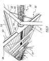
- An individual linear reflector 40 of the embodiments of the collector system shown in Figs. 5 to 10is shown in Fig. 11 , and comprises a planar reflector 42 or mirror which rests on a substrate 44 which is supported on the contoured structure 38.
- the support structure 38is connected to an electro-mechanically associated controller and drive system 46 which provides controlled rotation of the fixed array and its support structure to follow the daily motion of the sun (see Fig. 12 ).
- the focal receiver 36includes, in this embodiment, a concave secondary reflector 53 which heats a heat absorbing medium, such as pipe 52 through which is channelled a thermal conductor fluid or other heat conducting material which may be a solid, liquid or gas.
- the receivermay, for example, comprise a photovoltaic or thermo-voltaic cell.
- the heat absorbing mediumis ideally heated directly by reflected sunlight from the array of reflectors, and so the concave reflector 53 is used to reflect and further concentrate stray reflected sunlight upon the pipe 52.
- the focal receiver 36is supported by a stanchion 48 and intermediate supports 50.
- Fig. 15shows a mirror surface 70 comprising a fixed array of curvilinear reflectors 72 of another embodiment of solar energy collector system of the present invention, and the path 73 of sunlight reflected from the mirror surface 70 to a focus 74 at which is located a focal receiver of the system.
- Each curvilinear reflector 72is a discrete segment of a parabolic curve, all such curve segments having a common focus.
- the curvilinear reflectors 72are formed in a fixed array and define a substantially planar mirror surface, the array and its focal receiver being supported by a similarly planar structure 76 that is elevated and adapted to rotate about a single axis in the same way as occurs with the fixed array 34 of linear reflectors for the collector system 32 described above.
- there are air gaps between each adjacent row of reflectors 72although this is only a preferred feature. In some embodiments, there may be no air gaps between adjacent rows of reflectors.
- the support structuremay be rotated into a non-use, or "parked", position, such that the fixed array of reflectors defining the mirror surface points towards the ground, thereby protecting the mirror surface from the effect of harsh winds, rain, hail and other damage causing agents.
- This non-use positionis readily achievable primarily because the support structure for the fixed array of reflectors is elevated by an upright elevation assembly 77, and so the support structure can be rotated about a single axis in the manner as described above.
- a particularly preferred elevated support structureis rectangular in shape, as is shown in the embodiments of the invention described above, although other shapes may be used depending on circumstances.
- a rectangular support structurehas a framework of long, interconnected frame members at the front and rear of the collector system, and shorter length side frame numbers at the opposed sides or ends of the collector system and at intervals between the opposed sides. When supported by such a relatively shallow structure, the fixed array of reflectors defines a mirror surface that is substantially planar.
- the side frame members 79may be configured as upper and lower frame portions which can clamp the reflectors 72 therebetween by being locked together. They thus define the profiles of the parabolic segment reflectors necessary to achieve a common focus.
- Such upper and lower frame portions 82, 84 of a side frame memberare shown in Fig. 16 , and have complementary facing profiles 78, 80.
- the frame portions 82, 84can be manufactured by laser or water jet cutting at much lower cost and higher degree of accuracy than roll forming or curving techniques necessary to produce a curved frame or the like.
- the side frame membersmay comprise a lower frame portion 84 only, provided that the reflectors can be stably fixed thereto and the mirror surface created by an array of such reflectors is substantially planar.
- Other components of the support structuremay include stays, braces, spacers and other profile forming elements.
- FIG. 1Another form of support structure that may be used in the present invention is one utilizing an elevated central support spline, which is rotatable and has a plurality of fixed reflector support arms extending perpendicularly therefrom in opposite directions.
- the armssupport each row of reflectors as a fixed array and at suitable angles to achieve a common focus for sunlight reflected therefrom.
- the mirror surface defined by such an array, and supported in the aforementioned manner,is substantially planar and therefore much shallower than parabolic trough collectors.
- Such central splinesmay be tubular, trussed or otherwise configured to rotatably support the fixed array of reflectors.
- An elevated and rotatable support structure for the fixed array of reflectors which is substantially planaris simpler, more versatile, cheaper and easier to manufacture and erect than support structures for prior art solar collectors. It is also easier to rotate around an axis, such as at the centre of mass, than the larger and heavier parabolic trough collectors having the same aperture width.
- Shallow, substantially planar, support structures of this kindalso allow parabolic reflection to occur over a wider area than that which can occur with parabolic trough collectors, because a large number of rows of parabolic segment reflectors having a common focus can be spread over a wide area defined within a shallow, substantially planar support structure. The wider the area of mirror surface, the greater is the sunlight concentration ratio.
- Declination axis tracking of the movement of the sun through the seasons of a yearis also a feature of the solar energy collector system of the present invention.
- the upright support posts and other components of the elevation assembly for the support structureare suitably adjustable, whereby each row of reflectors is oriented at a common angle relative to the upright support posts.
- the present inventioncombines some of the advantages of linear Fresnel collectors and parabolic trough collectors.
- the present inventionuses a fixed array of reflectors extending in parallel rows to define a mirror surface. This embodiment simplifies manufacturing and reduces the requirements for the supporting structure and framing. Using an array of reflectors also allows the use of low cost mirror glass and standard building industry materials to minimise the cost of construction materials and equipment.
- the fixed array of reflectorsis supported by a shallow, substantially planar, structure which rotates about a single axis to avoid shading by adjacent reflectors at low sun angles.
- Each reflectoris positioned at a fixed angle adapted to focus sunlight onto a receiver to simplify the drive and control and positioning system.
- the aperture of the mirror surface of the system of the present inventionis optimally positioned such that the system is always pointed directly at the sun to optimize reflector efficiency, especially at low sun angles.
- the present inventionalso has advantages over the known prior art because of its compact shape and shallow form factor and, as a result, the collector system has a low applied load and bending moment.
- the collector systemmay also have a very low wind load due to its ventilated design, i.e. preferred gaps between rows of reflectors.
- the shallow form factor of the planar reflector framealso reduces wind loading and overturning moment typically associated with conventional parabolic trough reflector frames.
- the air gapsallow wind and air flow through the structure, thereby significantly reducing the associated wind loading.
- the substantially planar support structureallows for a significant reduction in the depth of the collector system.
Landscapes
- Engineering & Computer Science (AREA)
- Chemical & Material Sciences (AREA)
- Life Sciences & Earth Sciences (AREA)
- Sustainable Development (AREA)
- Sustainable Energy (AREA)
- Thermal Sciences (AREA)
- Physics & Mathematics (AREA)
- Combustion & Propulsion (AREA)
- Mechanical Engineering (AREA)
- General Engineering & Computer Science (AREA)
- Optical Elements Other Than Lenses (AREA)
- Photovoltaic Devices (AREA)
- Mounting And Adjusting Of Optical Elements (AREA)
Description
- The present invention relates to a solar energy collector system and, more particularly, to systems and methods for concentrating solar energy to generate heat and steam, such as may be used for electricity generation.
- Various types of solar energy collectors are known, and include non-concentrating types and concentrating types. Non-concentrating types intercept parallel unconcentrated rays of the sun with an array of detection or receiving devices such as a solar panel of photovoltaic cells or hot water pipes, for example. Photovoltaic cells use photovoltaic material to absorb sunlight and convert it directly to electricity. A concentrating type collector focuses energy rays using a special mirror surface assembly to concentrate the rays and create an intense beam of energy. Such assemblies generally comprise a parabolic reflector or lens assembly to reflect sunlight onto a focal receiver, usually in the form of a pipe carrying a thermal fluid capable of absorbing heat (such as highly refined paraffinic petroleum oil or molten salt), which is pumped to a heat exchanger that boils water. The boiling of water produces steam that drives turbines which generate electricity.
- Two common forms of concentrating type solar collectors are parabolic trough collectors and linear Fresnel collectors. A known
parabolic trough collector 10 is shown inFig. 1 . Sunlight is reflected from acurved mirror surface 12, generally of a parabolic shape, to a receiver 14 (containing a heat absorbing medium) positioned at the focus (or focal axis) of themirror surface 12. Themirror surface 12 and supporting structure is aligned on a north-south or east-west axis and rotates to track the daily motion of the sun. Commercial parabolic trough collector sites have mirror apertures of about 5 to 6 metres in width and are typically many hundreds of metres in length. - However, a problem with existing parabolic trough collectors utilising curved mirror glass is that the curved mirror is difficult and expensive to manufacture. Another problem with parabolic trough collectors is that the structure is heavy and cumbersome, requires strict design and manufacturing tolerances, typically requires complex rotating joints for the pipe carrying the thermal fluid, and is energy intensive to operate.
- A known linear Fresnel
collector 16 is shown inFig. 2 , in which sunlight is collected by anarray 18 of individual reflectors, all of which are identical to areflector 20, which is shown in more detail inFig. 3 . Thearray 18 is aligned in a north-south or east-west axis.Reflector 20 comprises a slightly concavelycurved mirror 22 which is mounted on aframe 24 pivotable onrollers 26 and 28 connected to a drive system. Alternative designs of linear Fresnel collector are also known, but all such designs share the essential attribute that, as shown inFig. 4 , each reflector must rotate individually and independently over the course of a day to reflect the sunlight to afocal receiver 30 containing a heat absorbing medium. - A problem with known linear Fresnel collectors is that they need individual drive and control and positioning systems for each reflector, and complex supporting structure, which adds considerably to the overall complexity, vulnerability to failure, and cost of the collector. Another problem with known linear Fresnel collectors is that adjacent reflectors shade each other at low sun angles, such as at dawn or sunset, which decreases the overall efficiency of the collector.
- The overall efficiency of linear Fresnel collectors is further decreased because of the relatively longer focal length required when compared to a parabolic trough collector of equivalent aperture width, and subsequent reflection losses at the remote edges of the mirror surface, particularly when the sun is at low angles. Sunlight striking the mirror surface at an acute angle reduces the amount of sunlight reflected upon the focal receiver, which approaches zero as the sun approaches the horizon.
- The closest known prior art revealed in searches conducted to date are hereinafter described.
- Japanese Patent Application No.
55112956A US Patent Application No. 2009/0314325 discloses a system having many focal points for its many parabolic reflector strips in each reflector module, rather than having a common elevated receiver to which incident solar radiation from the rows of reflectors is reflected. Also, each truss in that system supports a plurality of reflector modules, and each such truss rotates relative to the support frame. There is no fixed angle of the reflector modules relative to the support frame in that system, and the rotation axis of the support frame is perpendicular to the longitudinal axis of each truss. This allows the reflector modules to move relative to the support structure.US Patent Application No. 2009/0174957 discloses a system that utilises a plurality of planar reflecting mirrors which can be adjusted to different respective angles on the basis of the alignment of each mirror with an electric field, and no elevated and pivotable support structure for a fixed array of reflectors and a receiver is disclosed.US Patent Application No. 2009/0272425 discloses a system utilizing a parabolic main reflector, with the Fresnel lens only being used for refraction, not reflection.ES 2221789 A1 - It is an object of the present invention to provide a solar energy collector system that overcomes, or substantially ameliorates, the aforementioned shortcomings of the prior art, or at least provides a useful alternative.
- It is another object of the present invention to provide a solar energy collector system which is relatively light, does not require a complicated drive system, and is simple, versatile, cheap and easy to manufacture and erect compared to prior art solar collectors.
- According to the present invention there is provided a solar energy collector system comprising:
- (a) a fixed array of reflectors extending in parallel rows,
- (b) a common focal receiver located above the fixed array and extending parallel to the rows of reflectors and upon which incident solar radiation from all of the reflectors is reflected, the receiver including a heat absorbing medium adapted to absorb heat from the reflected radiation,
- (c) an elevated support structure having a substantially planar surface upon which the fixed array of reflectors is mounted, and the receiver mounted on the elevated support structure, wherein each row of reflectors is oriented at a respective fixed angle relative to the support structure, and
- (d) upright elevation means to which the support structure is pivotally mounted to allow controlled rotation of the fixed array and receiver simultaneously about a pivotal axis extending parallel to the rows of reflectors so as to track the movement of the sun, wherein the reflectors are curvilinear reflectors.
- In a preferred form, the receiver extends symmetrically of the array.
- It is preferred that the receiver comprises a pipe configured to channel a heat absorbing fluid.
- Preferably, the pivotal axis is a polar axis and extends symmetrically of the array.
- In another preferred form, controlled rotation of the fixed array and the receiver is provided by an electro-mechanically associated controller and drive system.
- It is preferred that adjacent parallel rows of reflectors are separated by an air gap.
- According to a yet further preferred form, the receiver further comprises a secondary reflector located above the pipe and configured to reflect to the pipe any reflected radiation from the reflector array which does not strike the pipe.
- The receiver preferably comprises a photovoltaic or thermo-voltaic cell.
- According to another preferred form of the invention, the system comprises a plurality of focal receivers.
- Preferably, the upright elevation means for the support structure includes an adjustable assembly for providing declination axis tracking of the movement of the sun through the seasons of a year, whereby each row of reflectors is oriented at a common adjustable angle relative to the upright elevation means.
- In order that the invention may be readily understood and put into practical effect, reference will now be made to the accompanying drawings, in which:
- Fig. 1
- is a perspective view of a prior art parabolic trough collector,
- Fig. 2
- is a perspective view of a prior art linear Fresnel collector,
- Fig. 3
- is a perspective view of a rotatable reflector assembly of the prior art linear Fresnel collector of
Fig. 2 , - Fig. 4
- is a side schematic view of the prior art linear Fresnel collector of
Fig. 2 and showing the general operation of similar types of solar collector, - Fig. 5
- is a perspective view of a solar energy collector system according to a preferred embodiment of the present invention,
- Fig. 6
- is a side view of the solar energy collector system of
Fig. 5 when aligned with a horizontal plane. - Fig. 7
- is an enlarged view of a portion of the mirror surface and support structure of the solar energy collector system as shown in
Fig. 6 . - Fig. 8
- is an end perspective view of the solar energy collector system of
Fig. 5 , - Fig. 9
- is a perspective view of the underside of the solar energy collector system of
Fig. 5 , and also shows another such system behind it, - Fig. 10
- is a side schematic view showing the path of sunlight reflected from a mirror surface comprising a fixed array of planar reflectors of a solar energy collector system according to another preferred embodiment of the present invention, the path reflected to a focus at which is located a focal receiver of the system,
- Fig. 11
- is a side view of an individual reflector of the mirror surface of a solar energy collector system of
Fig. 10 , - Fig. 12
- is a sequence of side views of a solar energy collector system utilizing the mirror surface shown in
Figs. 10 and 11 , showing the system tracking the daily motion of the sun across the sky, - Fig. 13
- is a side view of a solar energy collector system according to another preferred embodiment of the present invention, which has two focal receivers,
- Fig. 14
- is a side schematic view showing the path of sunlight reflected from the mirror surface to the focal receivers of the solar energy collector system of
Fig. 13 , - Fig. 15
- is a side schematic view showing the path of sunlight reflected from a mirror surface comprising a fixed array of curvilinear reflectors of a solar energy collector system according to another preferred embodiment of the present invention, the path reflected to a focus at which is located a focal receiver of the system,
- Fig. 16
- is a side schematic view of upper and lower frame portions of a support structure for a fixed array of curvilinear reflectors of a solar energy collector system according to
Fig. 15 . - A solar
energy collector system 32, according to a preferred embodiment of the present invention, is shown inFigs. 5 to 9 . Thecollector system 32 includes anarray 34 of linear reflectors defining a mirror surface, afocal receiver 36 for heating a heat absorbing medium located at the focus of the array 34 (i.e. the focal axis) and adapted to absorb heat from sunlight reflected from the linear reflectors, and astructure 38 adapted to support thearray 34 and thefocal receiver 36. Thereceiver 36 extends symmetrically of thearray 34. - However, unlike the prior art
linear Fresnel collector 16, thesupport structure 38 of thecollector system 32 is specially contoured, elevated and is adapted to rotate about asingle axis 39 such that the aperture of the mirror surface is at right angles to the plane of the mirror surface which is, in turn, constantly pointed at, or perpendicular to, the sun as shown inFig. 12 . Thepivotal axis 39 is, in this embodiment, the polar axis and extends symmetrically of the array. By contrast, the support structure of the prior art Fresnel collector 16 (seeFigs. 2, 3 and 4 ) is flat, affixed to the ground and unable to rotate. - The collector system of the present invention is further characterised in that each
reflector 40 is positioned at a fixed angle adapted to focus light ontoreceiver 36. This is shown by reference to the embodiment ofFig. 10 . The prior art Fresnel collector 16 (seeFig. 2 ) comprises reflectors (seeFig. 3 ) which must be rotated individually and independently (seeFig. 4 ) to track the daily motion of the sun. As a result, thecollector 32 obviates the need for individual drive and control and positioning systems for eachreflector 40, which considerably reduces the overall complexity, vulnerability to failure, and cost of thecollector system 32. - The present invention is further characterised in that the ability to rotate the
support structure 38 about asingle axis 39, usually but not necessarily located at the centre of mass of the collector system, greatly simplifies the design and assembly of the rotating joint necessary to convey the thermal fluid or other heat conducting material. - An individual
linear reflector 40 of the embodiments of the collector system shown inFigs. 5 to 10 is shown inFig. 11 , and comprises aplanar reflector 42 or mirror which rests on asubstrate 44 which is supported on the contouredstructure 38. - Referring to
Figs. 5 to 9 , thesupport structure 38 is connected to an electro-mechanically associated controller anddrive system 46 which provides controlled rotation of the fixed array and its support structure to follow the daily motion of the sun (seeFig. 12 ). - The
focal receiver 36 includes, in this embodiment, a concavesecondary reflector 53 which heats a heat absorbing medium, such aspipe 52 through which is channelled a thermal conductor fluid or other heat conducting material which may be a solid, liquid or gas. The receiver may, for example, comprise a photovoltaic or thermo-voltaic cell. The heat absorbing medium is ideally heated directly by reflected sunlight from the array of reflectors, and so theconcave reflector 53 is used to reflect and further concentrate stray reflected sunlight upon thepipe 52. Thefocal receiver 36 is supported by astanchion 48 andintermediate supports 50. Fig. 15 shows amirror surface 70 comprising a fixed array ofcurvilinear reflectors 72 of another embodiment of solar energy collector system of the present invention, and thepath 73 of sunlight reflected from themirror surface 70 to afocus 74 at which is located a focal receiver of the system. Eachcurvilinear reflector 72 is a discrete segment of a parabolic curve, all such curve segments having a common focus. Thecurvilinear reflectors 72 are formed in a fixed array and define a substantially planar mirror surface, the array and its focal receiver being supported by a similarlyplanar structure 76 that is elevated and adapted to rotate about a single axis in the same way as occurs with the fixedarray 34 of linear reflectors for thecollector system 32 described above. As with thecollector system 32, there are air gaps between each adjacent row ofreflectors 72, although this is only a preferred feature. In some embodiments, there may be no air gaps between adjacent rows of reflectors.- After use of the solar energy collector system of the present invention, the support structure may be rotated into a non-use, or "parked", position, such that the fixed array of reflectors defining the mirror surface points towards the ground, thereby protecting the mirror surface from the effect of harsh winds, rain, hail and other damage causing agents. This non-use position is readily achievable primarily because the support structure for the fixed array of reflectors is elevated by an
upright elevation assembly 77, and so the support structure can be rotated about a single axis in the manner as described above. - A particularly preferred elevated support structure is rectangular in shape, as is shown in the embodiments of the invention described above, although other shapes may be used depending on circumstances. A rectangular support structure has a framework of long, interconnected frame members at the front and rear of the collector system, and shorter length side frame numbers at the opposed sides or ends of the collector system and at intervals between the opposed sides. When supported by such a relatively shallow structure, the fixed array of reflectors defines a mirror surface that is substantially planar.
- For the fixed array of
curvilinear reflectors 72, theside frame members 79 may be configured as upper and lower frame portions which can clamp thereflectors 72 therebetween by being locked together. They thus define the profiles of the parabolic segment reflectors necessary to achieve a common focus. Such upper andlower frame portions Fig. 16 , and have complementary facing profiles 78, 80. Theframe portions lower frame portion 84 only, provided that the reflectors can be stably fixed thereto and the mirror surface created by an array of such reflectors is substantially planar. Other components of the support structure may include stays, braces, spacers and other profile forming elements. - Another form of support structure that may be used in the present invention is one utilizing an elevated central support spline, which is rotatable and has a plurality of fixed reflector support arms extending perpendicularly therefrom in opposite directions. The arms support each row of reflectors as a fixed array and at suitable angles to achieve a common focus for sunlight reflected therefrom. The mirror surface defined by such an array, and supported in the aforementioned manner, is substantially planar and therefore much shallower than parabolic trough collectors. Such central splines may be tubular, trussed or otherwise configured to rotatably support the fixed array of reflectors.
- An elevated and rotatable support structure for the fixed array of reflectors which is substantially planar is simpler, more versatile, cheaper and easier to manufacture and erect than support structures for prior art solar collectors. It is also easier to rotate around an axis, such as at the centre of mass, than the larger and heavier parabolic trough collectors having the same aperture width. Shallow, substantially planar, support structures of this kind also allow parabolic reflection to occur over a wider area than that which can occur with parabolic trough collectors, because a large number of rows of parabolic segment reflectors having a common focus can be spread over a wide area defined within a shallow, substantially planar support structure. The wider the area of mirror surface, the greater is the sunlight concentration ratio.
- Declination axis tracking of the movement of the sun through the seasons of a year is also a feature of the solar energy collector system of the present invention. To achieve this, the upright support posts and other components of the elevation assembly for the support structure are suitably adjustable, whereby each row of reflectors is oriented at a common angle relative to the upright support posts.
- The present invention combines some of the advantages of linear Fresnel collectors and parabolic trough collectors. The present invention uses a fixed array of reflectors extending in parallel rows to define a mirror surface. This embodiment simplifies manufacturing and reduces the requirements for the supporting structure and framing. Using an array of reflectors also allows the use of low cost mirror glass and standard building industry materials to minimise the cost of construction materials and equipment. The fixed array of reflectors is supported by a shallow, substantially planar, structure which rotates about a single axis to avoid shading by adjacent reflectors at low sun angles. Each reflector is positioned at a fixed angle adapted to focus sunlight onto a receiver to simplify the drive and control and positioning system. The aperture of the mirror surface of the system of the present invention is optimally positioned such that the system is always pointed directly at the sun to optimize reflector efficiency, especially at low sun angles.
- The present invention also has advantages over the known prior art because of its compact shape and shallow form factor and, as a result, the collector system has a low applied load and bending moment. The collector system may also have a very low wind load due to its ventilated design, i.e. preferred gaps between rows of reflectors.
- The shallow form factor of the planar reflector frame also reduces wind loading and overturning moment typically associated with conventional parabolic trough reflector frames. The air gaps allow wind and air flow through the structure, thereby significantly reducing the associated wind loading. The substantially planar support structure allows for a significant reduction in the depth of the collector system.
- It will be apparent to persons skilled in the art that various modifications may be made in details of design and construction of the solar energy collector system described above, including the addition of multiple focal receivers (see
receivers Figs. 13 and 14 , for example), without departing from the scope or ambit of the present invention. - It will also be apparent to persons skilled in the art that the scope of the invention is not limited only to the production of solar power and electricity, but may be adapted so as to produce solar process heat and steam for industrial and manufacturing processes and may be further adapted so as to include thermal storage and other means to improve overall system efficiency.
Claims (11)
- A solar energy collector system (32) comprising:(a) a fixed array of reflectors (34) extending in parallel rows,(b) a common focal receiver (36) located above the fixed array (34) and extending parallel to the rows of reflectors (40) and upon which incident solar radiation from all of the reflectors (72) is reflected, the receiver (36) including a heat absorbing medium adapted to absorb heat from the reflected radiation,(c) an elevated support structure (38) having a substantially planar surface upon which the fixed array of reflectors is mounted, and the receiver (36) mounted on the elevated support structure (38), wherein each row of reflectors is oriented at a respective fixed angle relative to the support structure, and(d) upright elevation means (77) to which the support structure is pivotally mounted to allow controlled rotation of the fixed array and receiver simultaneously about a pivotal axis (39) extending parallel to the rows of reflectors so as to track the movement of the sun,characterized in that the reflectors are curvilinear reflectors (72).
- The solar energy collector system of claim 1 wherein each of the curvilinear reflectors (72) is a discrete segment of a parabolic curve.
- The solar energy collector system of claim 1 wherein the receiver (36) extends symmetrically of the array (34).
- The solar energy collector system of claim 1 wherein the receiver (36) comprises a pipe (52) configured to channel a heat absorbing fluid.
- The solar energy collector system of claim 1 wherein the pivotal axis (39) is a polar axis and extends symmetrically of the array (34).
- The solar energy collector system of claim 1 wherein controlled rotation of the fixed array (34) and the receiver (36) is provided by an electro-mechanically associated controller and drive system (46).
- The solar energy collector system of claim 1 wherein adjacent parallel rows of reflectors are separated by an air gap.
- The solar energy collector system of claim 4 wherein the receiver further comprises a secondary reflector (53) located above the pipe (52) and configured to reflect to the pipe (52) any reflected radiation from the reflector array (34) which does not strike the pipe (52).
- The solar energy collector system of claim 1 wherein the receiver comprises a photovoltaic or thermo-voltaic cell.
- The solar energy collector system of claim 1 wherein the system comprises a plurality of focal receivers.
- The solar energy collector system of claim 1 wherein the upright elevation means for the support structure includes an adjustable assembly for providing declination axis tracking of the movement of the sun through the seasons of a year, whereby each row of reflectors is oriented at a common adjustable angle relative to the upright elevation means.
Applications Claiming Priority (2)
| Application Number | Priority Date | Filing Date | Title |
|---|---|---|---|
| AU2010901704AAU2010901704A0 (en) | 2010-04-22 | A solar collector | |
| PCT/AU2011/000460WO2011130794A1 (en) | 2010-04-22 | 2011-04-21 | A solar energy collector system |
Publications (3)
| Publication Number | Publication Date |
|---|---|
| EP2561287A1 EP2561287A1 (en) | 2013-02-27 |
| EP2561287A4 EP2561287A4 (en) | 2016-04-06 |
| EP2561287B1true EP2561287B1 (en) | 2019-06-12 |
Family
ID=44833560
Family Applications (1)
| Application Number | Title | Priority Date | Filing Date |
|---|---|---|---|
| EP11771406.3AActiveEP2561287B1 (en) | 2010-04-22 | 2011-04-21 | A solar energy collector system |
Country Status (12)
| Country | Link |
|---|---|
| US (1) | US8746236B2 (en) |
| EP (1) | EP2561287B1 (en) |
| CN (1) | CN103238033B (en) |
| AU (1) | AU2011242409B2 (en) |
| CL (1) | CL2012002928A1 (en) |
| ES (1) | ES2745116T3 (en) |
| IL (1) | IL222591A (en) |
| MA (1) | MA34164B1 (en) |
| MX (1) | MX2012012260A (en) |
| TN (1) | TN2012000502A1 (en) |
| WO (1) | WO2011130794A1 (en) |
| ZA (1) | ZA201208739B (en) |
Cited By (1)
| Publication number | Priority date | Publication date | Assignee | Title |
|---|---|---|---|---|
| EP3828478B1 (en)* | 2019-11-28 | 2025-05-07 | Commissariat à l'Energie Atomique et aux Energies Alternatives | Solar reflector comprising mirrors with rays of different curvature |
Families Citing this family (17)
| Publication number | Priority date | Publication date | Assignee | Title |
|---|---|---|---|---|
| JP5898674B2 (en)* | 2010-10-01 | 2016-04-06 | 国立大学法人東京工業大学 | Cross-line solar concentrator |
| FR2986060B1 (en)* | 2012-01-23 | 2020-02-21 | Amaterrasu | DEVICE FOR CAPTATION BY REFLECTION AND CONCENTRATION OF SOLAR RADIATION. |
| JP2013228184A (en)* | 2012-03-26 | 2013-11-07 | Ricoh Co Ltd | Linear solar concentrator and solar concentration power generation system |
| JP2013222733A (en)* | 2012-04-13 | 2013-10-28 | Honda Motor Co Ltd | Power generation system |
| US9194378B2 (en) | 2012-06-29 | 2015-11-24 | Black Sun Planetary Solutions, Inc. | Electromagnetic radiation collector |
| GB2506573A (en)* | 2012-07-06 | 2014-04-09 | Jean Pierre Dewerpe | Linear Fresnel Solar Concentrator |
| US10941963B2 (en) | 2014-03-24 | 2021-03-09 | Frenell Gmbh | Absorber system |
| ES2557501B1 (en)* | 2014-07-25 | 2016-11-02 | Solatom Csp, S.L. | Transportable linear fresnel solar system in a freight container |
| AU2015367285A1 (en)* | 2014-12-19 | 2017-07-13 | Trevor Powell | Reflector assembly for a solar collector |
| MA42283B1 (en)* | 2015-07-02 | 2020-07-29 | Chiyoda Corp | Earthing structure for solar heat capture device, solar heat capture device, and solar heat power generation system |
| ES2601222B1 (en)* | 2016-10-11 | 2017-09-15 | Universidad De Oviedo | Fresnel linear solar concentrator with triple movement |
| CN109611297B (en)* | 2018-12-14 | 2020-10-09 | 佛山科学技术学院 | A kind of self-adaptive illumination direction reflector condensing power generation device |
| CN114576870A (en)* | 2022-03-01 | 2022-06-03 | 西安热工研究院有限公司 | A kind of mirror adjustment device for molten salt tower type photothermal power station |
| US11652440B1 (en) | 2022-03-15 | 2023-05-16 | Bruce E. Clark | Frame elevated autonomous single axis 360 degree declination solar tracking array |
| WO2025071509A1 (en)* | 2023-09-29 | 2025-04-03 | Süleyman Demi̇rel Üni̇versi̇tesi̇ İdari̇ Ve Mali̇ İşler Dai̇re Başkanliği Genel Sekreterli̇k | Fixed trapezoidal fresnel mirror solar collector system |
| US12218623B1 (en) | 2024-07-19 | 2025-02-04 | DoubleLand LLC | Systems and methods for multi-position solar panel arrays |
| CN119766098B (en)* | 2024-12-25 | 2025-09-12 | 江苏实禹光电科技有限公司 | Multi-scale adjustable photovoltaic bracket |
Family Cites Families (15)
| Publication number | Priority date | Publication date | Assignee | Title |
|---|---|---|---|---|
| US4249514A (en)* | 1978-03-09 | 1981-02-10 | Westinghouse Electric Corp. | Tracking solar energy concentrator |
| US4243019A (en)* | 1978-10-25 | 1981-01-06 | Honeywell Inc. | Light-weight-trough type solar concentrator shell |
| JPS55112956A (en)* | 1979-02-21 | 1980-09-01 | Mitsubishi Heavy Ind Ltd | Solar heat collector |
| US4359041A (en)* | 1979-10-31 | 1982-11-16 | Snodgrass Erlin E | Light energy concentrating device |
| IL65238A (en)* | 1982-03-14 | 1987-01-30 | Naaman Ben Aharon | Linear concentrating solar collector |
| US5592932A (en)* | 1993-12-03 | 1997-01-14 | Yeomans; Allan J. | Radiant energy collecting apparatus |
| AUPR956801A0 (en)* | 2001-12-17 | 2002-01-24 | Kirk, Wayne Anthony | Solar energy conversion system |
| ES2221789B1 (en) | 2003-03-05 | 2006-04-01 | Jordi Universidad De Lleida | SOLAR THERMAL-PHOTOVOLTAIC CONCENTRATION GENERATOR BY SOLAR REFLECTION. |
| DE102008021730A1 (en)* | 2007-05-01 | 2008-11-06 | Samland und Aatz GbR (vertretungsberechtigte Gesellschafter: Thomas Samland, 78166 Donaueschingen, Bernd Aatz, 79244 Münstertal) | Solar system for converting solar electromagnetic radiation energy into electrical energy, has absorber arranged parallel to rotation axes of reflectors in center of module, and solar cells arranged in rows |
| CN100545693C (en)* | 2007-08-14 | 2009-09-30 | 北京实力源科技开发有限责任公司 | Solar-energy light collector and concentrating method |
| DE102007061153A1 (en)* | 2007-12-17 | 2009-06-25 | Erbslöh Aluminium Gmbh | Fresnel mirror and method for its production |
| US7736007B2 (en)* | 2008-01-05 | 2010-06-15 | Mario Rabinowitz | Polarization linkage of high dielectric constant pivoted planar solar concentrator mirrors |
| DE102008010314A1 (en)* | 2008-02-21 | 2009-08-27 | Gerbracht, Heiner, Dipl.-Ing. | Container and solar power plant |
| US7797939B2 (en)* | 2008-05-03 | 2010-09-21 | Timmy Green | Concentrating solar energy receiver |
| US7923624B2 (en)* | 2008-06-19 | 2011-04-12 | Solar Age Technologies | Solar concentrator system |
- 2011
- 2011-04-21MXMX2012012260Apatent/MX2012012260A/enactiveIP Right Grant
- 2011-04-21EPEP11771406.3Apatent/EP2561287B1/enactiveActive
- 2011-04-21ESES11771406Tpatent/ES2745116T3/enactiveActive
- 2011-04-21CNCN201180020298.7Apatent/CN103238033B/enactiveActive
- 2011-04-21WOPCT/AU2011/000460patent/WO2011130794A1/enactiveApplication Filing
- 2011-04-21USUS13/642,104patent/US8746236B2/enactiveActive
- 2011-04-21MAMA35318Apatent/MA34164B1/enunknown
- 2011-04-21AUAU2011242409Apatent/AU2011242409B2/enactiveActive
- 2012
- 2012-10-19CLCL2012002928Apatent/CL2012002928A1/enunknown
- 2012-10-21ILIL222591Apatent/IL222591A/enactiveIP Right Grant
- 2012-10-22TNTNP2012000502Apatent/TN2012000502A1/enunknown
- 2012-11-21ZAZA2012/08739Apatent/ZA201208739B/enunknown
Non-Patent Citations (1)
| Title |
|---|
| None* |
Cited By (1)
| Publication number | Priority date | Publication date | Assignee | Title |
|---|---|---|---|---|
| EP3828478B1 (en)* | 2019-11-28 | 2025-05-07 | Commissariat à l'Energie Atomique et aux Energies Alternatives | Solar reflector comprising mirrors with rays of different curvature |
Also Published As
| Publication number | Publication date |
|---|---|
| TN2012000502A1 (en) | 2014-04-01 |
| MA34164B1 (en) | 2013-04-03 |
| CL2012002928A1 (en) | 2013-06-07 |
| CN103238033A (en) | 2013-08-07 |
| EP2561287A1 (en) | 2013-02-27 |
| US8746236B2 (en) | 2014-06-10 |
| WO2011130794A1 (en) | 2011-10-27 |
| EP2561287A4 (en) | 2016-04-06 |
| IL222591A0 (en) | 2012-12-31 |
| ZA201208739B (en) | 2013-09-25 |
| US20130037072A1 (en) | 2013-02-14 |
| ES2745116T3 (en) | 2020-02-27 |
| IL222591A (en) | 2016-06-30 |
| AU2011242409B2 (en) | 2016-10-20 |
| CN103238033B (en) | 2016-03-02 |
| AU2011242409A1 (en) | 2012-12-06 |
| MX2012012260A (en) | 2012-11-23 |
Similar Documents
| Publication | Publication Date | Title |
|---|---|---|
| EP2561287B1 (en) | A solar energy collector system | |
| RU2134847C1 (en) | Radiant energy collection device | |
| US20100051016A1 (en) | Modular fresnel solar energy collection system | |
| US20100205963A1 (en) | Concentrated solar power generation system with distributed generation | |
| US20140182578A1 (en) | Solar concentrators, method of manufacturing and uses thereof | |
| US20100218807A1 (en) | 1-dimensional concentrated photovoltaic systems | |
| US20100051018A1 (en) | Linear solar energy collection system with secondary and tertiary reflectors | |
| US20100051015A1 (en) | Linear solar energy collection system | |
| US20160079461A1 (en) | Solar generator with focusing optics including toroidal arc lenses | |
| Yang et al. | Optical and thermal performance analysis of a micro parabolic trough collector for building integration | |
| WO2011145883A2 (en) | Photovoltaic power generation apparatus comprising a cylindrical light-collecting device | |
| US20190107311A1 (en) | Bladed solar thermal receivers for concentrating solar power | |
| US20100043777A1 (en) | Solar collector system | |
| Tripanagnostopoulos | New designs of building integrated solar energy systems | |
| US8474445B2 (en) | Concentrating solar energy device | |
| US9520519B2 (en) | Direct solar-radiation collection and concentration element and panel | |
| US20110214666A1 (en) | Fixed focus parabolic trough collector | |
| JP2012023108A (en) | Tower-type concentrating solar power generation system and its condensing method | |
| AU2015101876A4 (en) | Solar concentrator comprising flat mirrors oriented north-south and a cylindrical-parabolic secondary mirror having a central absorber | |
| RU2206837C2 (en) | Solar module with concentrator (alternatives) | |
| WO2018015598A1 (en) | Solar energy concentrator with movable mirrors for use in flat solar thermal collectors or in static photovoltaic modules | |
| US20210254861A1 (en) | Solar thermal receivers with multi-scale light trapping geometry and features | |
| CN102971590B (en) | device for collecting solar energy | |
| EP3221650B1 (en) | Solar concentrator with spaced pivotable connections | |
| WO2016098337A1 (en) | Solar concentrator with asymmetric tracking-integrated optics |
Legal Events
| Date | Code | Title | Description |
|---|---|---|---|
| PUAI | Public reference made under article 153(3) epc to a published international application that has entered the european phase | Free format text:ORIGINAL CODE: 0009012 | |
| 17P | Request for examination filed | Effective date:20121121 | |
| AK | Designated contracting states | Kind code of ref document:A1 Designated state(s):AL AT BE BG CH CY CZ DE DK EE ES FI FR GB GR HR HU IE IS IT LI LT LU LV MC MK MT NL NO PL PT RO RS SE SI SK SM TR | |
| DAX | Request for extension of the european patent (deleted) | ||
| RA4 | Supplementary search report drawn up and despatched (corrected) | Effective date:20160307 | |
| RIC1 | Information provided on ipc code assigned before grant | Ipc:F24J 2/54 20060101ALI20160301BHEP Ipc:F24J 2/38 20060101AFI20160301BHEP Ipc:F24J 2/10 20060101ALI20160301BHEP Ipc:F24J 2/18 20060101ALI20160301BHEP | |
| REG | Reference to a national code | Ref country code:DE Ref legal event code:R079 Ref document number:602011059668 Country of ref document:DE Free format text:PREVIOUS MAIN CLASS: F24J0002380000 Ipc:F24S0023700000 | |
| GRAP | Despatch of communication of intention to grant a patent | Free format text:ORIGINAL CODE: EPIDOSNIGR1 | |
| STAA | Information on the status of an ep patent application or granted ep patent | Free format text:STATUS: GRANT OF PATENT IS INTENDED | |
| RIC1 | Information provided on ipc code assigned before grant | Ipc:F24S 20/00 20180101ALI20181127BHEP Ipc:F24S 30/425 20180101ALI20181127BHEP Ipc:F24S 23/79 20180101ALI20181127BHEP Ipc:H01L 31/054 20140101ALI20181127BHEP Ipc:F24S 50/20 20180101ALI20181127BHEP Ipc:F24S 23/70 20180101AFI20181127BHEP | |
| INTG | Intention to grant announced | Effective date:20181219 | |
| RIC1 | Information provided on ipc code assigned before grant | Ipc:F24S 20/00 20180101ALI20181127BHEP Ipc:H01L 31/054 20140101ALI20181127BHEP Ipc:F24S 23/79 20180101ALI20181127BHEP Ipc:F24S 23/70 20180101AFI20181127BHEP Ipc:F24S 30/425 20180101ALI20181127BHEP Ipc:F24S 50/20 20180101ALI20181127BHEP | |
| GRAS | Grant fee paid | Free format text:ORIGINAL CODE: EPIDOSNIGR3 | |
| GRAA | (expected) grant | Free format text:ORIGINAL CODE: 0009210 | |
| STAA | Information on the status of an ep patent application or granted ep patent | Free format text:STATUS: THE PATENT HAS BEEN GRANTED | |
| AK | Designated contracting states | Kind code of ref document:B1 Designated state(s):AL AT BE BG CH CY CZ DE DK EE ES FI FR GB GR HR HU IE IS IT LI LT LU LV MC MK MT NL NO PL PT RO RS SE SI SK SM TR | |
| REG | Reference to a national code | Ref country code:GB Ref legal event code:FG4D | |
| REG | Reference to a national code | Ref country code:CH Ref legal event code:EP | |
| REG | Reference to a national code | Ref country code:AT Ref legal event code:REF Ref document number:1143074 Country of ref document:AT Kind code of ref document:T Effective date:20190615 | |
| REG | Reference to a national code | Ref country code:DE Ref legal event code:R096 Ref document number:602011059668 Country of ref document:DE | |
| REG | Reference to a national code | Ref country code:IE Ref legal event code:FG4D | |
| REG | Reference to a national code | Ref country code:NL Ref legal event code:MP Effective date:20190612 | |
| REG | Reference to a national code | Ref country code:LT Ref legal event code:MG4D | |
| PG25 | Lapsed in a contracting state [announced via postgrant information from national office to epo] | Ref country code:HR Free format text:LAPSE BECAUSE OF FAILURE TO SUBMIT A TRANSLATION OF THE DESCRIPTION OR TO PAY THE FEE WITHIN THE PRESCRIBED TIME-LIMIT Effective date:20190612 Ref country code:LT Free format text:LAPSE BECAUSE OF FAILURE TO SUBMIT A TRANSLATION OF THE DESCRIPTION OR TO PAY THE FEE WITHIN THE PRESCRIBED TIME-LIMIT Effective date:20190612 Ref country code:NO Free format text:LAPSE BECAUSE OF FAILURE TO SUBMIT A TRANSLATION OF THE DESCRIPTION OR TO PAY THE FEE WITHIN THE PRESCRIBED TIME-LIMIT Effective date:20190912 Ref country code:FI Free format text:LAPSE BECAUSE OF FAILURE TO SUBMIT A TRANSLATION OF THE DESCRIPTION OR TO PAY THE FEE WITHIN THE PRESCRIBED TIME-LIMIT Effective date:20190612 Ref country code:AL Free format text:LAPSE BECAUSE OF FAILURE TO SUBMIT A TRANSLATION OF THE DESCRIPTION OR TO PAY THE FEE WITHIN THE PRESCRIBED TIME-LIMIT Effective date:20190612 Ref country code:SE Free format text:LAPSE BECAUSE OF FAILURE TO SUBMIT A TRANSLATION OF THE DESCRIPTION OR TO PAY THE FEE WITHIN THE PRESCRIBED TIME-LIMIT Effective date:20190612 | |
| PG25 | Lapsed in a contracting state [announced via postgrant information from national office to epo] | Ref country code:BG Free format text:LAPSE BECAUSE OF FAILURE TO SUBMIT A TRANSLATION OF THE DESCRIPTION OR TO PAY THE FEE WITHIN THE PRESCRIBED TIME-LIMIT Effective date:20190912 Ref country code:RS Free format text:LAPSE BECAUSE OF FAILURE TO SUBMIT A TRANSLATION OF THE DESCRIPTION OR TO PAY THE FEE WITHIN THE PRESCRIBED TIME-LIMIT Effective date:20190612 Ref country code:LV Free format text:LAPSE BECAUSE OF FAILURE TO SUBMIT A TRANSLATION OF THE DESCRIPTION OR TO PAY THE FEE WITHIN THE PRESCRIBED TIME-LIMIT Effective date:20190612 Ref country code:GR Free format text:LAPSE BECAUSE OF FAILURE TO SUBMIT A TRANSLATION OF THE DESCRIPTION OR TO PAY THE FEE WITHIN THE PRESCRIBED TIME-LIMIT Effective date:20190913 | |
| REG | Reference to a national code | Ref country code:AT Ref legal event code:MK05 Ref document number:1143074 Country of ref document:AT Kind code of ref document:T Effective date:20190612 | |
| PG25 | Lapsed in a contracting state [announced via postgrant information from national office to epo] | Ref country code:EE Free format text:LAPSE BECAUSE OF FAILURE TO SUBMIT A TRANSLATION OF THE DESCRIPTION OR TO PAY THE FEE WITHIN THE PRESCRIBED TIME-LIMIT Effective date:20190612 Ref country code:SK Free format text:LAPSE BECAUSE OF FAILURE TO SUBMIT A TRANSLATION OF THE DESCRIPTION OR TO PAY THE FEE WITHIN THE PRESCRIBED TIME-LIMIT Effective date:20190612 Ref country code:AT Free format text:LAPSE BECAUSE OF FAILURE TO SUBMIT A TRANSLATION OF THE DESCRIPTION OR TO PAY THE FEE WITHIN THE PRESCRIBED TIME-LIMIT Effective date:20190612 Ref country code:PT Free format text:LAPSE BECAUSE OF FAILURE TO SUBMIT A TRANSLATION OF THE DESCRIPTION OR TO PAY THE FEE WITHIN THE PRESCRIBED TIME-LIMIT Effective date:20191014 Ref country code:RO Free format text:LAPSE BECAUSE OF FAILURE TO SUBMIT A TRANSLATION OF THE DESCRIPTION OR TO PAY THE FEE WITHIN THE PRESCRIBED TIME-LIMIT Effective date:20190612 Ref country code:NL Free format text:LAPSE BECAUSE OF FAILURE TO SUBMIT A TRANSLATION OF THE DESCRIPTION OR TO PAY THE FEE WITHIN THE PRESCRIBED TIME-LIMIT Effective date:20190612 Ref country code:CZ Free format text:LAPSE BECAUSE OF FAILURE TO SUBMIT A TRANSLATION OF THE DESCRIPTION OR TO PAY THE FEE WITHIN THE PRESCRIBED TIME-LIMIT Effective date:20190612 | |
| REG | Reference to a national code | Ref country code:ES Ref legal event code:FG2A Ref document number:2745116 Country of ref document:ES Kind code of ref document:T3 Effective date:20200227 | |
| PG25 | Lapsed in a contracting state [announced via postgrant information from national office to epo] | Ref country code:SM Free format text:LAPSE BECAUSE OF FAILURE TO SUBMIT A TRANSLATION OF THE DESCRIPTION OR TO PAY THE FEE WITHIN THE PRESCRIBED TIME-LIMIT Effective date:20190612 Ref country code:IS Free format text:LAPSE BECAUSE OF FAILURE TO SUBMIT A TRANSLATION OF THE DESCRIPTION OR TO PAY THE FEE WITHIN THE PRESCRIBED TIME-LIMIT Effective date:20191012 | |
| REG | Reference to a national code | Ref country code:DE Ref legal event code:R097 Ref document number:602011059668 Country of ref document:DE | |
| PLBE | No opposition filed within time limit | Free format text:ORIGINAL CODE: 0009261 | |
| STAA | Information on the status of an ep patent application or granted ep patent | Free format text:STATUS: NO OPPOSITION FILED WITHIN TIME LIMIT | |
| PG25 | Lapsed in a contracting state [announced via postgrant information from national office to epo] | Ref country code:DK Free format text:LAPSE BECAUSE OF FAILURE TO SUBMIT A TRANSLATION OF THE DESCRIPTION OR TO PAY THE FEE WITHIN THE PRESCRIBED TIME-LIMIT Effective date:20190612 Ref country code:PL Free format text:LAPSE BECAUSE OF FAILURE TO SUBMIT A TRANSLATION OF THE DESCRIPTION OR TO PAY THE FEE WITHIN THE PRESCRIBED TIME-LIMIT Effective date:20190612 | |
| 26N | No opposition filed | Effective date:20200313 | |
| PG25 | Lapsed in a contracting state [announced via postgrant information from national office to epo] | Ref country code:IS Free format text:LAPSE BECAUSE OF FAILURE TO SUBMIT A TRANSLATION OF THE DESCRIPTION OR TO PAY THE FEE WITHIN THE PRESCRIBED TIME-LIMIT Effective date:20200224 Ref country code:SI Free format text:LAPSE BECAUSE OF FAILURE TO SUBMIT A TRANSLATION OF THE DESCRIPTION OR TO PAY THE FEE WITHIN THE PRESCRIBED TIME-LIMIT Effective date:20190612 | |
| PG2D | Information on lapse in contracting state deleted | Ref country code:IS | |
| REG | Reference to a national code | Ref country code:DE Ref legal event code:R119 Ref document number:602011059668 Country of ref document:DE | |
| PG25 | Lapsed in a contracting state [announced via postgrant information from national office to epo] | Ref country code:MC Free format text:LAPSE BECAUSE OF FAILURE TO SUBMIT A TRANSLATION OF THE DESCRIPTION OR TO PAY THE FEE WITHIN THE PRESCRIBED TIME-LIMIT Effective date:20190612 | |
| REG | Reference to a national code | Ref country code:CH Ref legal event code:PL | |
| PG25 | Lapsed in a contracting state [announced via postgrant information from national office to epo] | Ref country code:DE Free format text:LAPSE BECAUSE OF NON-PAYMENT OF DUE FEES Effective date:20201103 Ref country code:LI Free format text:LAPSE BECAUSE OF NON-PAYMENT OF DUE FEES Effective date:20200430 Ref country code:CH Free format text:LAPSE BECAUSE OF NON-PAYMENT OF DUE FEES Effective date:20200430 Ref country code:FR Free format text:LAPSE BECAUSE OF NON-PAYMENT OF DUE FEES Effective date:20200430 Ref country code:LU Free format text:LAPSE BECAUSE OF NON-PAYMENT OF DUE FEES Effective date:20200421 | |
| REG | Reference to a national code | Ref country code:BE Ref legal event code:MM Effective date:20200430 | |
| PG25 | Lapsed in a contracting state [announced via postgrant information from national office to epo] | Ref country code:BE Free format text:LAPSE BECAUSE OF NON-PAYMENT OF DUE FEES Effective date:20200430 | |
| GBPC | Gb: european patent ceased through non-payment of renewal fee | Effective date:20200421 | |
| PG25 | Lapsed in a contracting state [announced via postgrant information from national office to epo] | Ref country code:GB Free format text:LAPSE BECAUSE OF NON-PAYMENT OF DUE FEES Effective date:20200421 Ref country code:IE Free format text:LAPSE BECAUSE OF NON-PAYMENT OF DUE FEES Effective date:20200421 | |
| PG25 | Lapsed in a contracting state [announced via postgrant information from national office to epo] | Ref country code:MT Free format text:LAPSE BECAUSE OF FAILURE TO SUBMIT A TRANSLATION OF THE DESCRIPTION OR TO PAY THE FEE WITHIN THE PRESCRIBED TIME-LIMIT Effective date:20190612 Ref country code:CY Free format text:LAPSE BECAUSE OF FAILURE TO SUBMIT A TRANSLATION OF THE DESCRIPTION OR TO PAY THE FEE WITHIN THE PRESCRIBED TIME-LIMIT Effective date:20190612 | |
| PG25 | Lapsed in a contracting state [announced via postgrant information from national office to epo] | Ref country code:MK Free format text:LAPSE BECAUSE OF FAILURE TO SUBMIT A TRANSLATION OF THE DESCRIPTION OR TO PAY THE FEE WITHIN THE PRESCRIBED TIME-LIMIT Effective date:20190612 | |
| PGFP | Annual fee paid to national office [announced via postgrant information from national office to epo] | Ref country code:ES Payment date:20240513 Year of fee payment:14 | |
| PGFP | Annual fee paid to national office [announced via postgrant information from national office to epo] | Ref country code:IT Payment date:20240419 Year of fee payment:14 | |
| PGFP | Annual fee paid to national office [announced via postgrant information from national office to epo] | Ref country code:TR Payment date:20240416 Year of fee payment:14 |