EP2560711B1 - Medicament delivery device - Google Patents
Medicament delivery deviceDownload PDFInfo
- Publication number
- EP2560711B1 EP2560711B1EP11772317.1AEP11772317AEP2560711B1EP 2560711 B1EP2560711 B1EP 2560711B1EP 11772317 AEP11772317 AEP 11772317AEP 2560711 B1EP2560711 B1EP 2560711B1
- Authority
- EP
- European Patent Office
- Prior art keywords
- rib
- housing
- medicament delivery
- delivery device
- actuation
- Prior art date
- Legal status (The legal status is an assumption and is not a legal conclusion. Google has not performed a legal analysis and makes no representation as to the accuracy of the status listed.)
- Active
Links
Images


Classifications
- A—HUMAN NECESSITIES
- A61—MEDICAL OR VETERINARY SCIENCE; HYGIENE
- A61M—DEVICES FOR INTRODUCING MEDIA INTO, OR ONTO, THE BODY; DEVICES FOR TRANSDUCING BODY MEDIA OR FOR TAKING MEDIA FROM THE BODY; DEVICES FOR PRODUCING OR ENDING SLEEP OR STUPOR
- A61M5/00—Devices for bringing media into the body in a subcutaneous, intra-vascular or intramuscular way; Accessories therefor, e.g. filling or cleaning devices, arm-rests
- A61M5/178—Syringes
- A61M5/31—Details
- A—HUMAN NECESSITIES
- A61—MEDICAL OR VETERINARY SCIENCE; HYGIENE
- A61M—DEVICES FOR INTRODUCING MEDIA INTO, OR ONTO, THE BODY; DEVICES FOR TRANSDUCING BODY MEDIA OR FOR TAKING MEDIA FROM THE BODY; DEVICES FOR PRODUCING OR ENDING SLEEP OR STUPOR
- A61M5/00—Devices for bringing media into the body in a subcutaneous, intra-vascular or intramuscular way; Accessories therefor, e.g. filling or cleaning devices, arm-rests
- A61M5/178—Syringes
- A61M5/20—Automatic syringes, e.g. with automatically actuated piston rod, with automatic needle injection, filling automatically
- A61M5/2033—Spring-loaded one-shot injectors with or without automatic needle insertion
- A—HUMAN NECESSITIES
- A61—MEDICAL OR VETERINARY SCIENCE; HYGIENE
- A61M—DEVICES FOR INTRODUCING MEDIA INTO, OR ONTO, THE BODY; DEVICES FOR TRANSDUCING BODY MEDIA OR FOR TAKING MEDIA FROM THE BODY; DEVICES FOR PRODUCING OR ENDING SLEEP OR STUPOR
- A61M5/00—Devices for bringing media into the body in a subcutaneous, intra-vascular or intramuscular way; Accessories therefor, e.g. filling or cleaning devices, arm-rests
- A61M5/178—Syringes
- A61M5/31—Details
- A61M5/3129—Syringe barrels
- A—HUMAN NECESSITIES
- A61—MEDICAL OR VETERINARY SCIENCE; HYGIENE
- A61M—DEVICES FOR INTRODUCING MEDIA INTO, OR ONTO, THE BODY; DEVICES FOR TRANSDUCING BODY MEDIA OR FOR TAKING MEDIA FROM THE BODY; DEVICES FOR PRODUCING OR ENDING SLEEP OR STUPOR
- A61M5/00—Devices for bringing media into the body in a subcutaneous, intra-vascular or intramuscular way; Accessories therefor, e.g. filling or cleaning devices, arm-rests
- A61M5/178—Syringes
- A61M5/31—Details
- A61M2005/3103—Leak prevention means for distal end of syringes, i.e. syringe end for mounting a needle
- A61M2005/3104—Caps for syringes without needle
- A—HUMAN NECESSITIES
- A61—MEDICAL OR VETERINARY SCIENCE; HYGIENE
- A61M—DEVICES FOR INTRODUCING MEDIA INTO, OR ONTO, THE BODY; DEVICES FOR TRANSDUCING BODY MEDIA OR FOR TAKING MEDIA FROM THE BODY; DEVICES FOR PRODUCING OR ENDING SLEEP OR STUPOR
- A61M5/00—Devices for bringing media into the body in a subcutaneous, intra-vascular or intramuscular way; Accessories therefor, e.g. filling or cleaning devices, arm-rests
- A61M5/178—Syringes
- A61M5/31—Details
- A61M5/3129—Syringe barrels
- A61M5/3137—Specially designed finger grip means, e.g. for easy manipulation of the syringe rod
Definitions
- the present inventionrelates to a medicament delivery device and in particular a device with improved grip abilities for users and an activation locking function.
- the pen-shapeis then difficult to grip in a secure and positive way.
- the deviceis then made with a form and size providing a better grip which then means that the size of the device increases and thus becomes more difficult to bring along and use in a discrete way.
- WO 9810813Another example of an "enlarged" device is disclosed in document WO 9810813 , which also is on the market under the trade name InnoLet®.
- the deviceis developed for diabetes treatment of elderly with reduced strength where a dose setting is performed by turning a large dial similar to an egg-clock dial. Further the distal end of the device is arranged with a very large activation button in order to facilitate activation of the injection.
- the deviceis rather bulky and not so easy to bring along in for example a pocket.
- a medicament delivery devicecomprising an elongated housing having opposite distal and proximal ends, comprising; a grip member connected to the elongated housing and movable between a rest position in which the device has a predetermined grip size and an operation position in which the pre-determined grip size of the device is increased for providing an improved grip of the device during use, wherein said grip member comprises an elongated arc-shaped rib arranged extending in the longitudinal direction of the device and being rotatably attached to the housing and wherein the housing is designed comprising opposite first and second surface parts, wherein the first surface part comprises an elongated arc-shape, and wherein the second surface part is generally parallel with the longitudinal axis of the device, such that when the rib is in the rest position, the first surface part and an inner surface of the rib are abutting each other such that the predetermined grip size of the device is the distance between the second surface part and an outer surface of the rib, and when the grip member comprises an elongated arc-shaped
- said ribis arranged with limiting means arranged to co-act with corresponding limiting means of the housing.
- the ribcomprises a support member arranged to be in contact with said housing for preventing a radial movement of said rib when said rib is in the operation position and said device is gripped by a user.
- the medicament delivery deviceis an injection device.
- said housingis arranged to accommodate a medicament container.
- said devicefurther comprises actuation means and drive means interactively connected to each other, and wherein said drive means are arranged within said elongated housing and capable of, upon manual activation of said actuation means, acting on a movable stopper inside said medicament container for expelling a dose of medicament.
- said devicefurther comprises a hold and release means; wherein said hold and release means are interactively connected to the drive means for holding said drive means in a pre-tensioned state, and to the actuation means, such that when the actuation means are activated said hold and release means release the drive means from the pre-tensioned state.
- said actuation meansis interactively connected to the rib and to the housing, and wherein said actuation means is movable between a locked position in which said actuation means and said housing are interlocked to each other by actuation interlocking means when the rib is in the rest position, and a released position in which said actuation means are released from said housing when the rib is in the operation position, such that the actuation button can be activated for interacting with the hold and release means and thereby release the drive means from the pre-tensioned state.
- said devicefurther comprises a protective cap releasibly attached to the proximal end of the housing, operably connected to said rib and movable between a closed position in which said protective cap and said rib are interlocked to each other when said rib is in the rest position and an open position in which said protective cap is removed such that the rib can be moved from the rest position to the operation position.
- said devicefurther comprises a protective cap releasibly attached to the proximal end of the housing and operably connected to said rib, such that said protective cap and said rib are interlocked to each other when said rib is in the rest position and such that said protective cap and said rib are released from each other when said rib is in the operation position such that said cap can be removed.
- the grip memberwhich is movable from a rest position to an operation position, the grip size can be enlarged at the moment when the device is to be used, thus providing an improved grip for the user.
- the grip memberwhen the device is not in use, i.e. in rest position, the grip member is positioned in the rest position and the size of the device is almost as if no grip member was present.
- the design of the longitudinally extending and curved ribgives a good size enlargement and improved grip with very little extra material.
- the use of a support memberfurther enhances the improved grip of the device.
- Another advantage with the grip memberis the possibility of the extra function as a safety lock of the actuation means.
- this aspectwhen the locking and unlocking of the actuation means is performed by moving it, this action and the force required to do it is simplified and reduced respectively when the grip member is used for the rotation.
- distal part/endrefers to the part/end of the medicament delivery device, or the parts/ends of the members thereof, which under use of the medicament delivery device is located the furthest away from the medicament delivery site.
- proximal part/endrefers to the part/end of the medicament delivery device, or the parts/ends of the members thereof, which under use of the medicament delivery device is located closest to the medicament delivery site.
- the wording grip sizeis defined as the distance D between the thumb and the rest of the fingers of a users hand when an object is gripped. See Fig. 8 . Consequently, the grip size of an object is the distance between two opposite surfaces of a grip area.
- the medicament delivery devicecomprises an elongated housing 10 having opposite distal 48 and proximal 12 ends; a grip member connected to the elongated housing and movable between a rest position in which the device has a predetermined grip size and an operation position in which the pre-determined grip size of the device is increased for providing an improved grip of the device during use.
- the grip membercomprises an elongated arc-shaped rib 64 arranged extending in the longitudinal direction of the device and being rotatably attached to the housing. Said rib being arranged with limiting means arranged to co-act with corresponding limiting means of the housing.
- the housingis designed comprising opposite first 74 and second 76 surface parts, wherein the first surface part comprises an elongated arc-shape, and wherein the second surface part is generally parallel with the longitudinal axis of the device, such that when the rib is in the rest position, the first surface part and an inner surface of the rib are abutting each other such that the predetermined grip size of the device is the distance between the second surface part and an outer surface of the rib, and when the rib is in the operation position, the rib is positioned opposite to the first part surface such that the increased predetermined grip size is the distance between the outer surface of the rib and the first surface part.
- the ribcomprises also a support member 78 arranged to be in contact with said housing for preventing a radial movement of said rib when said rib is in the operation position and said device is gripped by a user.
- the exemplary deviceis an injection device and more particularly an auto-injection device.
- the exemplary devicecomprises a generally elongated housing 10 having opposite distal 48 and proximal 12 ends.
- the exemplary embodimentis made by two halves.
- the housingmay comprise more or less components for e.g. manufacturing and assembly reasons.
- the housingis further arranged with a compartment intended to house a medicament container 18 containing medicament to be expelled through a medicament delivery member such as an injection needle, a mouth piece, a nozzle or the like.
- a medicament delivery membersuch as an injection needle, a mouth piece, a nozzle or the like.
- a stopper 20is arranged to be movable.
- the medicament containeris preferably transparent and is visible via a transparent window 21 as a part of the housing 10. In this way the content of the medicament container is visible for a user.
- the devicefurther comprises drive means arranged within said elongated housing and capable of acting on the movable stopper 20 inside said medicament container 18 for expelling a dose of medicament, a hold and release means and an actuation means; wherein said hold and release means are interactively connected to the drive means for holding said drive means in a pre-tensioned state, and to the actuation means, such that when the actuations means are activated said hold and release means release the drive means from the pre-tensioned state.
- the devicemay only comprise actuation means and drive means interactively connected to each other, and wherein said drive means are arranged within said elongated housing and capable of, upon manual activation of said actuation means, acting on the movable stopper 20 inside said medicament container for expelling a dose of medicament.
- the drive means of the exemplary embodimentare shown in Fig. 2 and comprise a plunger rod 22 and a resilient member as e.g. a compression spring arranged around the plunger rod.
- the plunger rodcomprises a proximal end which is in contact with the stopper 20.
- the drive meansare positioned in a tubular part 24 of the housing as seen in Fig. 4 .
- the resilient member 26is arranged between an annular ledge 28 at the proximal end of the plunger rod and an end wall 30 of the tubular part 24, Figs. 2 and 6 .
- the end wall 30 of the tubular partis further arranged with a central passage 32 through which distal end of the plunger rod 22 extends.
- a distally directed surface 34 of the end wall 30is bevelled as seen in Fig. 6 .
- the hold and release means of the exemplary embodimentis shown in Figs. 3 , 4 and 6 ; comprises a lock member 40 having flexible arms 42, wherein each flexible arm is provided with a radial inwardly directed ledge 44.
- the distal end of the plunger rod 22is arranged with an enlargement 36, providing a proximally directed annular ledge 38.
- the lock member 40is arranged in contact with the distal end of the plunger rod 22 such that the radial inwardly directed ledges 44 are in contact with the annular ledge 38 of the enlargement 36 of the plunger rod, thus holding the drive means in the pre-tensioned state, Figs. 2 and 6 .
- the grip memberis in the form of an elongated arc-shaped rib 64 extending in the longitudinal direction of the device and is rotatably attached to the housing, and the actuation means is in the form of an actuation button 46.
- the proximal end of the grip memberis arranged with a ring portion 66 that surrounds the proximal neck portion of the housing.
- the distal end of the grip memberis also arranged with a ring portion 68 that surrounds the actuation button 46.
- the rib 64displays an arc-shape extension as seen in the transversal direction of the device.
- the housing 10is designed such that the first surface part 74 thereof generally follows the curvature of said rib when in the rest position and that the second surface part 76 thereof which is positioned generally 180 degrees in relation to the first surface part 74 and which is generally parallel with the longitudinal axis of the device, creates a pre-determined distance to said rib when the rib is in the operation position.
- the support member 78 of the ribis in the form of a pin attached to the inner surface of the rib 64 and projects in a direction transversal to the longitudinal axis of the device.
- the first surface part 74 of the housing 10is further arranged with a cut-out 80 for accommodating the support member when the grip member is in the rest position.
- the grip memberis further arranged with limiting means arranged to co-act with corresponding limiting means of the housing such that said rib can only be turned in one direction and generally 180 degrees between said rest position and said operation position.
- the limiting meansis a first stop ledge 82, Fig. 7a , attached to the proximally directed surface of the distal ring portion 68 and the corresponding limiting means is a corresponding second stop ledge 84, Fig. 7b , arranged on the distal end surface of the housing.
- the two ledges 82, 84thus provide a rotational stop in one direction so that the grip member 62 may only be rotated in one direction as will be described below.
- the actuation meansis interactively connected to the rib and to the housing, and wherein said actuation means is movable between a locked position in which said actuation means and said housing are interlocked to each other by actuation interlocking means when the rib is in the rest position, and a released position in which said actuation means are released from said housing when the rib is in the operation position, such that the actuation means can be activated for interacting with the hold and release means and thereby release the drive means from the pre-tensioned state.
- the actuation meanscomprises the actuation button 46 arranged surrounding the lock member 40 and the tubular part 24.
- the actuation button 46being in the form of a generally tubular actuation button and having a distal end protruding through the distal end 48 of the housing 10.
- the inner surface of the actuation buttonis arranged with an annular ring 50 which is in contact with the outer surfaces of the arms 42 of the lock member 40.
- the actuation buttonis connected to the housing by two circumferential grooves 52, 54 on the outer surface of the actuation button and by a protrusion 56 on the inner surface of the housing, Fig. 6 .
- the actuation buttonis further interactively connected to the housing by the actuation interlocking means.
- the actuation interlocking meansbeing a proximally directed pin 58, Fig.
- the actuation buttonis also interactively connected to the rib by a track groove 72 arranged on the outer surface of the actuation button and by a guide member 70 in the form of an inwardly protruding ledge, Fig. 4 , arranged on the inner surface of the ring portion 68.
- Said guide member 70being arranged to fit into the track groove 72 of the actuation button 46, and wherein the track groove 72 has a certain extension in both the longitudinal direction as well as in the circumferential direction.
- the protrusion 56 on the inner surface of the housingfits into one of the circumferential grooves for preventing the actuation button 46 to be moved in the distal direction out of the housing 10 but allowing rotation of the actuation button in relation to the housing as will be described.
- the devicefurther comprises a protective cap 16 releasibly attached to the proximal end of the housing, operably connected to said rib and movable between a closed position in which said protective cap and said rib are interlocked to each other by appropriate interlocking means when said rib is in the rest position, and an open position in which said protective cap is removed such that the rib can be moved from the rest position to the operation position.
- the proximal end 12 of the housingis arranged with a neck portion arranged with engagement means as e.g. thread segments on its outer surface and the protective cap 16 is releasably attached to the neck portion by appropriate engagement means.
- the protective cap 16may also be releasibly attached to the proximal end of the housing and operably connected to said rib, such that said protective cap and said rib are interlocked to each other when said rib is in the rest position and such that said protective cap and said rib are released from each other when said rib is in the operation position such that said cap can be removed.
- the device of the exemplary embodimentis intended to function as follows.
- the protective cap 16is attached to the proximal end of the device and a medicament container 18 is placed inside the device.
- the grip memberis in the rest position.
- the connection between the grip member and the actuation button 46is such that in the rest position, the pin 58 of the actuation button 46 is in contact with the ledge 60 of the housing 10 so that the actuation button 46 cannot be depressed.
- the protective cap 16When a dose of medicament is to be delivered to the user, the protective cap 16 is removed and a medicament delivery member is either attached or exposed.
- the grip memberis now turned about 180 degrees around the longitudinal axis of the device to the second surface part 76 and thus to the operation position, whereby the stop ledges 82, 84 ascertain that the grip member may only be rotated in one direction and about 180 degrees.
- the grip size of the deviceincreases due to that the transversal measure is increased by the rib 64 and thus the grip size becomes larger and the device becomes easier for a user to grip and hold.
- the ribis prevented from flexing in the radial direction by the support member 78 in contact with the second surface part 76.
- the turning of the grip memberhas also caused a turning of the actuation button 46 because of the ledge 70 acting on a side edge of a groove 72 on the actuation button, whereby the proximally directed pin 58 of the actuation button 46 is moved out of contact with the ledge 60 of the housing.
- the actuation buttoncan thus be pressed in the proximal direction which also is enabled by the ledge 70 moving in the longitudinal direction in the groove 72 of the actuation button 46, which movement of the actuation button causes the annular ring 50 of the actuation button also to move in the proximal direction in relation to the lock member 40 such that the ring 50 is moved out of contact with the arms 42.
- the protrusions 56 on the inner surface of the housingare moved into the second annular groove 54 of the actuation button 46 such that when the user then releases the actuation button 46, it becomes locked in the depressed position.
- the protective cap 16can now be returned onto the proximal end of the device for avoiding e.g. accidental needle sticks if the medicament delivery member is an injection needle. Then the grip member 62 may be returned to its initial position and the device may be discarded.
- the groove 72 of the actuation buttonhas such an extension in the circumferential direction so that only the button may be rotated for actuating the device. This gives an option not to use the grip member in certain instances if the user is capable of turning the actuation button and/or can hold the device in a good grip without the aid of the grip member.
Landscapes
- Health & Medical Sciences (AREA)
- Vascular Medicine (AREA)
- Engineering & Computer Science (AREA)
- Anesthesiology (AREA)
- Biomedical Technology (AREA)
- Heart & Thoracic Surgery (AREA)
- Hematology (AREA)
- Life Sciences & Earth Sciences (AREA)
- Animal Behavior & Ethology (AREA)
- General Health & Medical Sciences (AREA)
- Public Health (AREA)
- Veterinary Medicine (AREA)
- Infusion, Injection, And Reservoir Apparatuses (AREA)
Description
- The present invention relates to a medicament delivery device and in particular a device with improved grip abilities for users and an activation locking function.
- There is a large number of medicament delivery devices that have been invented and developed that are intended for self-medication by a patient or a user. In particular pen-like injectors have been developed where the intention is to have a device preferably displaying a number of automatic or semi-automatic functions such as mixing, priming, penetration, injection and/or withdrawal. From a patient's or user's point of view the device should be easy and intuitive to use and often at the same time with a reduced size so that it is easy to bring along and discrete when used. These different demands are not always so easy to combine in one device because an increased number of functions add to the necessary size of the device. On the other hand, for some patients the pen-shape is not ideal, especially for persons with reduced dexterity in the hands. The pen-shape is then difficult to grip in a secure and positive way. In those cases and for that type of patients, the device is then made with a form and size providing a better grip which then means that the size of the device increases and thus becomes more difficult to bring along and use in a discrete way.
- One example of an "enlarged" device is disclosed in document
WO 9810813 - It is also desirable that such devices possess a premature activation locking function until a cap has been removed and/or until a delivery member has been attached to the device.
- Also, there is thus still a demand for a device that can provide a good and secure grip even for persons with reduced dexterity and/or strength of the hands and yet is small and easy to bring along.
- There is a main objective with the present invention to provide a medicament delivery device that does not display the drawbacks of the state of the art medicament delivery devices.
- According to a main aspect of the invention it is characterised by a medicament delivery device comprising an elongated housing having opposite distal and proximal ends, comprising; a grip member connected to the elongated housing and movable between a rest position in which the device has a predetermined grip size and an operation position in which the pre-determined grip size of the device is increased for providing an improved grip of the device during use, wherein said grip member comprises an elongated arc-shaped rib arranged extending in the longitudinal direction of the device and being rotatably attached to the housing and wherein the housing is designed comprising opposite first and second surface parts, wherein the first surface part comprises an elongated arc-shape, and wherein the second surface part is generally parallel with the longitudinal axis of the device, such that when the rib is in the rest position, the first surface part and an inner surface of the rib are abutting each other such that the predetermined grip size of the device is the distance between the second surface part and an outer surface of the rib, and when the rib is in the operation position, the rib is positioned opposite to the first part surface such that the increased predetermined grip size is the distance between the outer surface of the rib and the first surface part.
- According to another aspect of the invention said rib is arranged with limiting means arranged to co-act with corresponding limiting means of the housing.
- According to yet another aspect of the invention the rib comprises a support member arranged to be in contact with said housing for preventing a radial movement of said rib when said rib is in the operation position and said device is gripped by a user.
- According to a further aspect of the invention the medicament delivery device is an injection device.
- According to yet a further aspect of the invention said housing is arranged to accommodate a medicament container.
- According to another aspect of the invention said device further comprises actuation means and drive means interactively connected to each other, and wherein said drive means are arranged within said elongated housing and capable of, upon manual activation of said actuation means, acting on a movable stopper inside said medicament container for expelling a dose of medicament.
- According to yet another aspect of the invention said device further comprises a hold and release means; wherein said hold and release means are interactively connected to the drive means for holding said drive means in a pre-tensioned state, and to the actuation means, such that when the actuation means are activated said hold and release means release the drive means from the pre-tensioned state.
- According to a further aspect of the invention said actuation means is interactively connected to the rib and to the housing, and wherein said actuation means is movable between a locked position in which said actuation means and said housing are interlocked to each other by actuation interlocking means when the rib is in the rest position, and a released position in which said actuation means are released from said housing when the rib is in the operation position, such that the actuation button can be activated for interacting with the hold and release means and thereby release the drive means from the pre-tensioned state.
- According to yet a further aspect of the invention said device further comprises a protective cap releasibly attached to the proximal end of the housing, operably connected to said rib and movable between a closed position in which said protective cap and said rib are interlocked to each other when said rib is in the rest position and an open position in which said protective cap is removed such that the rib can be moved from the rest position to the operation position.
- According to another aspect of the invention said device further comprises a protective cap releasibly attached to the proximal end of the housing and operably connected to said rib, such that said protective cap and said rib are interlocked to each other when said rib is in the rest position and such that said protective cap and said rib are released from each other when said rib is in the operation position such that said cap can be removed.
- There are a number of advantages with the present invention. Due to the grip member which is movable from a rest position to an operation position, the grip size can be enlarged at the moment when the device is to be used, thus providing an improved grip for the user. On the other hand, when the device is not in use, i.e. in rest position, the grip member is positioned in the rest position and the size of the device is almost as if no grip member was present.
- The design of the longitudinally extending and curved rib gives a good size enlargement and improved grip with very little extra material. The use of a support member further enhances the improved grip of the device.
- Another advantage with the grip member is the possibility of the extra function as a safety lock of the actuation means. In this aspect, when the locking and unlocking of the actuation means is performed by moving it, this action and the force required to do it is simplified and reduced respectively when the grip member is used for the rotation.
- These and other aspects of, and advantages with, the present invention will become apparent from the following detailed description of the invention and from the accompanying drawings.
- In the following detailed description of the invention, reference will be made to the accompanying drawings, of which
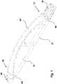
- Fig. 1
- is a perspective view of a medicament delivery device of the present invention in a rest position,
- Fig. 2
- is a cross-sectional view of the device of
Fig. 1 , - Fig. 3
- is an exploded view of the device of
Fig. 1 , - Fig. 4
- is an exploded view according to
Fig. 3 rotated 180 degrees, - Fig. 5
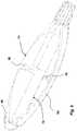
- is a perspective view according to
Fig. 1 in an operation position, - Fig. 6
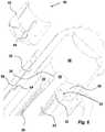
- is a detailed view of a distal part of the device of
Fig. 1 , and - Figs. 7 a,b
- are detailed views of the device of
Fig. 1 . - Fig. 8
- is a view of a hand of a user for defining the grip size wording.
- In the present application, when the term "distal part/end" is used, this refers to the part/end of the medicament delivery device, or the parts/ends of the members thereof, which under use of the medicament delivery device is located the furthest away from the medicament delivery site. Correspondingly, when the term "proximal part/end" is used, this refers to the part/end of the medicament delivery device, or the parts/ends of the members thereof, which under use of the medicament delivery device is located closest to the medicament delivery site.
- In the present application, the wording grip size is defined as the distance D between the thumb and the rest of the fingers of a users hand when an object is gripped. See
Fig. 8 . Consequently, the grip size of an object is the distance between two opposite surfaces of a grip area. - The medicament delivery device according to the invention comprises an
elongated housing 10 having opposite distal 48 and proximal 12 ends; a grip member connected to the elongated housing and movable between a rest position in which the device has a predetermined grip size and an operation position in which the pre-determined grip size of the device is increased for providing an improved grip of the device during use. - The grip member comprises an elongated arc-
shaped rib 64 arranged extending in the longitudinal direction of the device and being rotatably attached to the housing. Said rib being arranged with limiting means arranged to co-act with corresponding limiting means of the housing. - The housing is designed comprising opposite first 74 and second 76 surface parts, wherein the first surface part comprises an elongated arc-shape, and wherein the second surface part is generally parallel with the longitudinal axis of the device, such that when the rib is in the rest position, the first surface part and an inner surface of the rib are abutting each other such that the predetermined grip size of the device is the distance between the second surface part and an outer surface of the rib, and when the rib is in the operation position, the rib is positioned opposite to the first part surface such that the increased predetermined grip size is the distance between the outer surface of the rib and the first surface part.
- Further, the rib comprises also a
support member 78 arranged to be in contact with said housing for preventing a radial movement of said rib when said rib is in the operation position and said device is gripped by a user. - An exemplary embodiment but not restricted to it is shown in the
figures1-7 . The exemplary device is an injection device and more particularly an auto-injection device. The exemplary device comprises a generally elongatedhousing 10 having opposite distal 48 and proximal 12 ends. InFig. 1 the exemplary embodiment is made by two halves. In this context it is to be understood that the housing may comprise more or less components for e.g. manufacturing and assembly reasons. - The housing is further arranged with a compartment intended to house a
medicament container 18 containing medicament to be expelled through a medicament delivery member such as an injection needle, a mouth piece, a nozzle or the like. Inside the medicament container 18 astopper 20 is arranged to be movable. The medicament container is preferably transparent and is visible via atransparent window 21 as a part of thehousing 10. In this way the content of the medicament container is visible for a user. - The device further comprises drive means arranged within said elongated housing and capable of acting on the
movable stopper 20 inside saidmedicament container 18 for expelling a dose of medicament, a hold and release means and an actuation means; wherein said hold and release means are interactively connected to the drive means for holding said drive means in a pre-tensioned state, and to the actuation means, such that when the actuations means are activated said hold and release means release the drive means from the pre-tensioned state. - It is to be understood that the device may only comprise actuation means and drive means interactively connected to each other, and wherein said drive means are arranged within said elongated housing and capable of, upon manual activation of said actuation means, acting on the
movable stopper 20 inside said medicament container for expelling a dose of medicament. - The drive means of the exemplary embodiment are shown in
Fig. 2 and comprise aplunger rod 22 and a resilient member as e.g. a compression spring arranged around the plunger rod. The plunger rod comprises a proximal end which is in contact with thestopper 20. The drive means are positioned in atubular part 24 of the housing as seen inFig. 4 . Theresilient member 26 is arranged between anannular ledge 28 at the proximal end of the plunger rod and anend wall 30 of thetubular part 24,Figs. 2 and6 . Theend wall 30 of the tubular part is further arranged with acentral passage 32 through which distal end of theplunger rod 22 extends. A distally directedsurface 34 of theend wall 30 is bevelled as seen inFig. 6 . - The hold and release means of the exemplary embodiment is shown in
Figs. 3 ,4 and6 ; comprises alock member 40 havingflexible arms 42, wherein each flexible arm is provided with a radial inwardly directedledge 44. The distal end of theplunger rod 22 is arranged with anenlargement 36, providing a proximally directedannular ledge 38. Thelock member 40 is arranged in contact with the distal end of theplunger rod 22 such that the radial inwardly directedledges 44 are in contact with theannular ledge 38 of theenlargement 36 of the plunger rod, thus holding the drive means in the pre-tensioned state,Figs. 2 and6 . - In the exemplary embodiment, as shown in
Figs. 1-5 , the grip member is in the form of an elongated arc-shapedrib 64 extending in the longitudinal direction of the device and is rotatably attached to the housing, and the actuation means is in the form of anactuation button 46. The proximal end of the grip member is arranged with aring portion 66 that surrounds the proximal neck portion of the housing. The distal end of the grip member is also arranged with aring portion 68 that surrounds theactuation button 46. Therib 64 displays an arc-shape extension as seen in the transversal direction of the device. Thehousing 10 is designed such that thefirst surface part 74 thereof generally follows the curvature of said rib when in the rest position and that thesecond surface part 76 thereof which is positioned generally 180 degrees in relation to thefirst surface part 74 and which is generally parallel with the longitudinal axis of the device, creates a pre-determined distance to said rib when the rib is in the operation position. Thesupport member 78 of the rib is in the form of a pin attached to the inner surface of therib 64 and projects in a direction transversal to the longitudinal axis of the device. Thefirst surface part 74 of thehousing 10 is further arranged with a cut-out 80 for accommodating the support member when the grip member is in the rest position. The grip member is further arranged with limiting means arranged to co-act with corresponding limiting means of the housing such that said rib can only be turned in one direction and generally 180 degrees between said rest position and said operation position. In the exemplary embodiment, the limiting means is afirst stop ledge 82,Fig. 7a , attached to the proximally directed surface of thedistal ring portion 68 and the corresponding limiting means is a correspondingsecond stop ledge 84,Fig. 7b , arranged on the distal end surface of the housing. The twoledges - In the exemplary embodiment, the actuation means is interactively connected to the rib and to the housing, and wherein said actuation means is movable between a locked position in which said actuation means and said housing are interlocked to each other by actuation interlocking means when the rib is in the rest position, and a released position in which said actuation means are released from said housing when the rib is in the operation position, such that the actuation means can be activated for interacting with the hold and release means and thereby release the drive means from the pre-tensioned state. In the exemplary embodiment, the actuation means comprises the
actuation button 46 arranged surrounding thelock member 40 and thetubular part 24. Theactuation button 46 being in the form of a generally tubular actuation button and having a distal end protruding through thedistal end 48 of thehousing 10. The inner surface of the actuation button is arranged with anannular ring 50 which is in contact with the outer surfaces of thearms 42 of thelock member 40. The actuation button is connected to the housing by twocircumferential grooves protrusion 56 on the inner surface of the housing,Fig. 6 . The actuation button is further interactively connected to the housing by the actuation interlocking means. In the exemplary embodiment, the actuation interlocking means being a proximally directedpin 58,Fig. 3 , and anannular ledge 60,Fig. 4 , on the inner surface of the housing. The actuation button is also interactively connected to the rib by atrack groove 72 arranged on the outer surface of the actuation button and by aguide member 70 in the form of an inwardly protruding ledge,Fig. 4 , arranged on the inner surface of thering portion 68. Saidguide member 70 being arranged to fit into thetrack groove 72 of theactuation button 46, and wherein thetrack groove 72 has a certain extension in both the longitudinal direction as well as in the circumferential direction. As seen inFig. 6 , theprotrusion 56 on the inner surface of the housing fits into one of the circumferential grooves for preventing theactuation button 46 to be moved in the distal direction out of thehousing 10 but allowing rotation of the actuation button in relation to the housing as will be described. - The device further comprises a
protective cap 16 releasibly attached to the proximal end of the housing, operably connected to said rib and movable between a closed position in which said protective cap and said rib are interlocked to each other by appropriate interlocking means when said rib is in the rest position, and an open position in which said protective cap is removed such that the rib can be moved from the rest position to the operation position. Theproximal end 12 of the housing is arranged with a neck portion arranged with engagement means as e.g. thread segments on its outer surface and theprotective cap 16 is releasably attached to the neck portion by appropriate engagement means. - It is also to be understood that the
protective cap 16 may also be releasibly attached to the proximal end of the housing and operably connected to said rib, such that said protective cap and said rib are interlocked to each other when said rib is in the rest position and such that said protective cap and said rib are released from each other when said rib is in the operation position such that said cap can be removed. - The device of the exemplary embodiment is intended to function as follows. When the device is delivered to a user, the
protective cap 16 is attached to the proximal end of the device and amedicament container 18 is placed inside the device. The grip member is in the rest position. The connection between the grip member and theactuation button 46 is such that in the rest position, thepin 58 of theactuation button 46 is in contact with theledge 60 of thehousing 10 so that theactuation button 46 cannot be depressed. - When a dose of medicament is to be delivered to the user, the
protective cap 16 is removed and a medicament delivery member is either attached or exposed. The grip member is now turned about 180 degrees around the longitudinal axis of the device to thesecond surface part 76 and thus to the operation position, whereby the stop ledges 82, 84 ascertain that the grip member may only be rotated in one direction and about 180 degrees. As seen fromFig. 5 the grip size of the device increases due to that the transversal measure is increased by therib 64 and thus the grip size becomes larger and the device becomes easier for a user to grip and hold. The rib is prevented from flexing in the radial direction by thesupport member 78 in contact with thesecond surface part 76. - The turning of the grip member has also caused a turning of the
actuation button 46 because of theledge 70 acting on a side edge of agroove 72 on the actuation button, whereby the proximally directedpin 58 of theactuation button 46 is moved out of contact with theledge 60 of the housing. The actuation button can thus be pressed in the proximal direction which also is enabled by theledge 70 moving in the longitudinal direction in thegroove 72 of theactuation button 46, which movement of the actuation button causes theannular ring 50 of the actuation button also to move in the proximal direction in relation to thelock member 40 such that thering 50 is moved out of contact with thearms 42. This in turn enables thearms 42 to flex radially outwards because of the proximal ends of thearms 42 coming in contact with the bevelleddistal surface 34 of thetubular part 24 of thehousing 10. Theplunger rod 22 is now free to move and is urged in the proximal direction by thecompression spring 26, whereby thestopper 20 is forced in the proximal direction inside themedicament container 18 and a dose of medicament is expelled through the medicament delivery member. - When the user presses the
actuation button 46 theprotrusions 56 on the inner surface of the housing are moved into the secondannular groove 54 of theactuation button 46 such that when the user then releases theactuation button 46, it becomes locked in the depressed position. Theprotective cap 16 can now be returned onto the proximal end of the device for avoiding e.g. accidental needle sticks if the medicament delivery member is an injection needle. Then the grip member 62 may be returned to its initial position and the device may be discarded. - The
groove 72 of the actuation button has such an extension in the circumferential direction so that only the button may be rotated for actuating the device. This gives an option not to use the grip member in certain instances if the user is capable of turning the actuation button and/or can hold the device in a good grip without the aid of the grip member. - It is to be understood that the embodiment described above and shown in the drawings is to be regarded only as a non-limiting example of the invention and that it may be modified in many ways within the scope of the patent claims.
Claims (10)
- Medicament delivery device comprising an elongated housing (10) having opposite distal (48) and proximal (12) ends, comprising;
a grip member connected to the elongated housing and movable between a rest position in which the device has a predetermined grip size and an operation position in which the pre-determined grip size of the device is increased for providing an improved grip of the device during use,
characterised in that
said grip member comprises an elongated arc-shaped rib (64) arranged extending in the longitudinal direction of the device and being rotatably attached to the housing andin that the housing is designed comprising opposite first (74) and second (76) surface parts, wherein the first surface part comprises an elongated arc-shape, and wherein the second surface part is generally parallel with the longitudinal axis of the device, such that when the rib is in the rest position, the first surface part and an inner surface of the rib are abutting each other such that the predetermined grip size of the device is the distance between the second surface part and an outer surface of the rib, and when the rib is in the operation position, the rib is positioned opposite to the first part surface such that the increased predetermined grip size is the distance between the outer surface of the rib and the first surface part. - Medicament delivery device according to claim 1, wherein said rib is arranged with limiting means arranged to co-act with corresponding limiting means of the housing.
- Medicament delivery device according to claim 1 or 2, wherein the rib comprises a support member (78) arranged to be in contact with said housing for preventing a radial movement of said rib when said rib is in the operation position and said device is gripped by a user.
- Medicament delivery device according to any one of the preceding claims, wherein the medicament delivery device is an injection device.
- Medicament delivery device according to any of the claims 1-4, wherein said housing (10) is arranged to accommodate a medicament container (18).
- Medicament delivery device according to claim 5, wherein said device further comprises actuation means and drive means interactively connected to each other, and wherein said drive means are arranged within said elongated housing and capable of, upon manual activation of said actuation means, acting on a movable stopper (20) inside said medicament container for expelling a dose of medicament.
- Medicament delivery device according to claim 6, wherein said device further comprises a hold and release means; wherein said hold and release means are interactively connected to the drive means for holding said drive means in a pre-tensioned state, and to the actuation means, such that when the actuation means are activated said hold and release means release the drive means from the pre-tensioned state.
- Medicament delivery device according to claim 7, wherein said actuation means is interactively connected to the rib and to the housing, and wherein said actuation means is movable between a locked position in which said actuation means and said housing are interlocked to each other by actuation interlocking means when the rib is in the rest position, and a released position in which said actuation means are released from said housing when the rib is in the operation position, such that the actuation button can be activated for interacting with the hold and release means and thereby release the drive means from the pre-tensioned state.
- Medicament delivery device according to any one of the preceding claims 1-8, wherein said device further comprises a protective cap (16) releasibly attached to the proximal end of the housing, operably connected to said rib and movable between a closed position in which said protective cap and said rib are interlocked to each other when said rib is in the rest position and an open position in which said protective cap is removed such that the rib can be moved from the rest position to the operation position.
- Medicament delivery device according to any one of the preceding claims 1-8, wherein said device further comprises a protective cap (16) releasibly attached to the proximal end of the housing and operably connected to said rib, such that said protective cap and said rib are interlocked to each other when said rib is in the rest position and such that said protective cap and said rib are released from each other when said rib is in the operation position such that said cap can be removed.
Applications Claiming Priority (3)
| Application Number | Priority Date | Filing Date | Title |
|---|---|---|---|
| US32553710P | 2010-04-19 | 2010-04-19 | |
| SE1050385 | 2010-04-19 | ||
| PCT/SE2011/050427WO2011133086A1 (en) | 2010-04-19 | 2011-04-08 | Medicament delivery device |
Publications (3)
| Publication Number | Publication Date |
|---|---|
| EP2560711A1 EP2560711A1 (en) | 2013-02-27 |
| EP2560711A4 EP2560711A4 (en) | 2016-12-21 |
| EP2560711B1true EP2560711B1 (en) | 2018-02-28 |
Family
ID=44834374
Family Applications (1)
| Application Number | Title | Priority Date | Filing Date |
|---|---|---|---|
| EP11772317.1AActiveEP2560711B1 (en) | 2010-04-19 | 2011-04-08 | Medicament delivery device |
Country Status (6)
| Country | Link |
|---|---|
| US (1) | US8926566B2 (en) |
| EP (1) | EP2560711B1 (en) |
| CN (1) | CN102939122B (en) |
| DK (1) | DK2560711T3 (en) |
| TW (1) | TWI419722B (en) |
| WO (1) | WO2011133086A1 (en) |
Families Citing this family (7)
| Publication number | Priority date | Publication date | Assignee | Title |
|---|---|---|---|---|
| CN102971034B (en)* | 2010-05-20 | 2015-01-21 | Shl集团有限责任公司 | drug delivery device |
| US20120064481A1 (en)* | 2010-09-13 | 2012-03-15 | Wade Cannon | Composite delivery system |
| US9477642B2 (en) | 2012-02-05 | 2016-10-25 | Apple Inc. | Gesture-based navigation among content items |
| USD926975S1 (en)* | 2018-09-27 | 2021-08-03 | Phc Holdings Corporation | Cartridge for medicine injector |
| DK180318B1 (en) | 2019-04-15 | 2020-11-09 | Apple Inc | Systems, methods, and user interfaces for interacting with multiple application windows |
| USD930828S1 (en)* | 2020-02-03 | 2021-09-14 | Becton Dickinson France | Injector housing |
| USD930827S1 (en)* | 2020-02-03 | 2021-09-14 | Becton Dickinson France | Injector housing |
Family Cites Families (9)
| Publication number | Priority date | Publication date | Assignee | Title |
|---|---|---|---|---|
| UA49912C2 (en)* | 1996-09-13 | 2002-10-15 | Ново Нордіск А/С | Device for dose indication in injection syringe |
| US5865804A (en)* | 1997-07-16 | 1999-02-02 | Bachynsky; Nicholas | Rotary cam syringe |
| DE20103363U1 (en)* | 2001-02-26 | 2001-05-17 | Braun Melsungen Ag | Protection device for an injection needle |
| US6149626A (en)* | 1997-10-03 | 2000-11-21 | Bachynsky; Nicholas | Automatic injecting syringe apparatus |
| EP1635896A1 (en)* | 2003-06-20 | 2006-03-22 | Allergan, Inc. | Needless injectors |
| US7611495B1 (en)* | 2005-10-07 | 2009-11-03 | Gianturco Michael C | Device for manually controlling delivery rate of a hypodermic syringe and syringe having same |
| WO2007108768A1 (en)* | 2006-03-20 | 2007-09-27 | Doxa Ab | Mixing and injection system for injectable biomaterials or artificial materials in orthopaedic applications |
| US9358348B2 (en) | 2006-06-14 | 2016-06-07 | Covidien Lp | Safety shield for medical needles |
| CN101932350B (en)* | 2008-01-28 | 2013-04-17 | Shl集团有限责任公司 | Syringes with thumb-operable rollers |
- 2011
- 2011-04-08USUS13/641,105patent/US8926566B2/enactiveActive
- 2011-04-08CNCN201180029725.8Apatent/CN102939122B/ennot_activeExpired - Fee Related
- 2011-04-08DKDK11772317.1Tpatent/DK2560711T3/enactive
- 2011-04-08WOPCT/SE2011/050427patent/WO2011133086A1/enactiveApplication Filing
- 2011-04-08EPEP11772317.1Apatent/EP2560711B1/enactiveActive
- 2011-04-18TWTW100113316Apatent/TWI419722B/ennot_activeIP Right Cessation
Non-Patent Citations (1)
| Title |
|---|
| None* |
Also Published As
| Publication number | Publication date |
|---|---|
| EP2560711A1 (en) | 2013-02-27 |
| CN102939122A (en) | 2013-02-20 |
| CN102939122B (en) | 2014-11-05 |
| TW201141566A (en) | 2011-12-01 |
| WO2011133086A1 (en) | 2011-10-27 |
| EP2560711A4 (en) | 2016-12-21 |
| US20130204194A1 (en) | 2013-08-08 |
| DK2560711T3 (en) | 2018-05-07 |
| US8926566B2 (en) | 2015-01-06 |
| TWI419722B (en) | 2013-12-21 |
Similar Documents
| Publication | Publication Date | Title |
|---|---|---|
| EP2560711B1 (en) | Medicament delivery device | |
| KR101745226B1 (en) | Medicament delivery device | |
| EP2496292B1 (en) | Medicament delivery device | |
| JP5597729B2 (en) | Drug supply device | |
| EP2575937B1 (en) | Medicament delivery device | |
| US9579458B2 (en) | Medicament delivery device | |
| US10881797B2 (en) | Drive mechanism for an autoinjector | |
| DK2903665T3 (en) | MEDICINAL DELIVERY DEVICE WITH SHUTTER BUTTON | |
| TW201244768A (en) | Medicament delivery device | |
| EP3265153B1 (en) | Medicament delivery device | |
| EP3568177B1 (en) | Medicament delivery device | |
| KR20170120633A (en) | A dose setting mechanism, and a dose setting mechanism. | |
| US11400228B2 (en) | Medicament delivery device | |
| HK1209069B (en) | Medicament delivery device with trigger button |
Legal Events
| Date | Code | Title | Description |
|---|---|---|---|
| PUAI | Public reference made under article 153(3) epc to a published international application that has entered the european phase | Free format text:ORIGINAL CODE: 0009012 | |
| 17P | Request for examination filed | Effective date:20121016 | |
| AK | Designated contracting states | Kind code of ref document:A1 Designated state(s):AL AT BE BG CH CY CZ DE DK EE ES FI FR GB GR HR HU IE IS IT LI LT LU LV MC MK MT NL NO PL PT RO RS SE SI SK SM TR | |
| DAX | Request for extension of the european patent (deleted) | ||
| RA4 | Supplementary search report drawn up and despatched (corrected) | Effective date:20161122 | |
| RIC1 | Information provided on ipc code assigned before grant | Ipc:A61M 5/31 20060101AFI20161116BHEP Ipc:A61M 5/20 20060101ALI20161116BHEP | |
| GRAP | Despatch of communication of intention to grant a patent | Free format text:ORIGINAL CODE: EPIDOSNIGR1 | |
| INTG | Intention to grant announced | Effective date:20171020 | |
| RAP1 | Party data changed (applicant data changed or rights of an application transferred) | Owner name:SHL GROUP AB | |
| GRAS | Grant fee paid | Free format text:ORIGINAL CODE: EPIDOSNIGR3 | |
| GRAA | (expected) grant | Free format text:ORIGINAL CODE: 0009210 | |
| AK | Designated contracting states | Kind code of ref document:B1 Designated state(s):AL AT BE BG CH CY CZ DE DK EE ES FI FR GB GR HR HU IE IS IT LI LT LU LV MC MK MT NL NO PL PT RO RS SE SI SK SM TR | |
| REG | Reference to a national code | Ref country code:GB Ref legal event code:FG4D Ref country code:CH Ref legal event code:EP | |
| REG | Reference to a national code | Ref country code:AT Ref legal event code:REF Ref document number:973464 Country of ref document:AT Kind code of ref document:T Effective date:20180315 | |
| REG | Reference to a national code | Ref country code:IE Ref legal event code:FG4D | |
| REG | Reference to a national code | Ref country code:FR Ref legal event code:PLFP Year of fee payment:8 | |
| REG | Reference to a national code | Ref country code:DE Ref legal event code:R096 Ref document number:602011046053 Country of ref document:DE | |
| REG | Reference to a national code | Ref country code:DK Ref legal event code:T3 Effective date:20180504 | |
| REG | Reference to a national code | Ref country code:SE Ref legal event code:TRGR | |
| PGFP | Annual fee paid to national office [announced via postgrant information from national office to epo] | Ref country code:BE Payment date:20180314 Year of fee payment:8 | |
| REG | Reference to a national code | Ref country code:NL Ref legal event code:MP Effective date:20180228 | |
| REG | Reference to a national code | Ref country code:LT Ref legal event code:MG4D | |
| REG | Reference to a national code | Ref country code:AT Ref legal event code:MK05 Ref document number:973464 Country of ref document:AT Kind code of ref document:T Effective date:20180228 | |
| PG25 | Lapsed in a contracting state [announced via postgrant information from national office to epo] | Ref country code:CY Free format text:LAPSE BECAUSE OF FAILURE TO SUBMIT A TRANSLATION OF THE DESCRIPTION OR TO PAY THE FEE WITHIN THE PRESCRIBED TIME-LIMIT Effective date:20180228 Ref country code:LT Free format text:LAPSE BECAUSE OF FAILURE TO SUBMIT A TRANSLATION OF THE DESCRIPTION OR TO PAY THE FEE WITHIN THE PRESCRIBED TIME-LIMIT Effective date:20180228 Ref country code:NO Free format text:LAPSE BECAUSE OF FAILURE TO SUBMIT A TRANSLATION OF THE DESCRIPTION OR TO PAY THE FEE WITHIN THE PRESCRIBED TIME-LIMIT Effective date:20180528 Ref country code:FI Free format text:LAPSE BECAUSE OF FAILURE TO SUBMIT A TRANSLATION OF THE DESCRIPTION OR TO PAY THE FEE WITHIN THE PRESCRIBED TIME-LIMIT Effective date:20180228 Ref country code:NL Free format text:LAPSE BECAUSE OF FAILURE TO SUBMIT A TRANSLATION OF THE DESCRIPTION OR TO PAY THE FEE WITHIN THE PRESCRIBED TIME-LIMIT Effective date:20180228 Ref country code:ES Free format text:LAPSE BECAUSE OF FAILURE TO SUBMIT A TRANSLATION OF THE DESCRIPTION OR TO PAY THE FEE WITHIN THE PRESCRIBED TIME-LIMIT Effective date:20180228 Ref country code:HR Free format text:LAPSE BECAUSE OF FAILURE TO SUBMIT A TRANSLATION OF THE DESCRIPTION OR TO PAY THE FEE WITHIN THE PRESCRIBED TIME-LIMIT Effective date:20180228 | |
| PGFP | Annual fee paid to national office [announced via postgrant information from national office to epo] | Ref country code:DK Payment date:20180410 Year of fee payment:8 Ref country code:CH Payment date:20180416 Year of fee payment:8 | |
| PG25 | Lapsed in a contracting state [announced via postgrant information from national office to epo] | Ref country code:BG Free format text:LAPSE BECAUSE OF FAILURE TO SUBMIT A TRANSLATION OF THE DESCRIPTION OR TO PAY THE FEE WITHIN THE PRESCRIBED TIME-LIMIT Effective date:20180528 Ref country code:AT Free format text:LAPSE BECAUSE OF FAILURE TO SUBMIT A TRANSLATION OF THE DESCRIPTION OR TO PAY THE FEE WITHIN THE PRESCRIBED TIME-LIMIT Effective date:20180228 Ref country code:RS Free format text:LAPSE BECAUSE OF FAILURE TO SUBMIT A TRANSLATION OF THE DESCRIPTION OR TO PAY THE FEE WITHIN THE PRESCRIBED TIME-LIMIT Effective date:20180228 Ref country code:LV Free format text:LAPSE BECAUSE OF FAILURE TO SUBMIT A TRANSLATION OF THE DESCRIPTION OR TO PAY THE FEE WITHIN THE PRESCRIBED TIME-LIMIT Effective date:20180228 Ref country code:GR Free format text:LAPSE BECAUSE OF FAILURE TO SUBMIT A TRANSLATION OF THE DESCRIPTION OR TO PAY THE FEE WITHIN THE PRESCRIBED TIME-LIMIT Effective date:20180529 | |
| PGFP | Annual fee paid to national office [announced via postgrant information from national office to epo] | Ref country code:SE Payment date:20180411 Year of fee payment:8 | |
| PG25 | Lapsed in a contracting state [announced via postgrant information from national office to epo] | Ref country code:IT Free format text:LAPSE BECAUSE OF FAILURE TO SUBMIT A TRANSLATION OF THE DESCRIPTION OR TO PAY THE FEE WITHIN THE PRESCRIBED TIME-LIMIT Effective date:20180228 Ref country code:EE Free format text:LAPSE BECAUSE OF FAILURE TO SUBMIT A TRANSLATION OF THE DESCRIPTION OR TO PAY THE FEE WITHIN THE PRESCRIBED TIME-LIMIT Effective date:20180228 Ref country code:PL Free format text:LAPSE BECAUSE OF FAILURE TO SUBMIT A TRANSLATION OF THE DESCRIPTION OR TO PAY THE FEE WITHIN THE PRESCRIBED TIME-LIMIT Effective date:20180228 Ref country code:RO Free format text:LAPSE BECAUSE OF FAILURE TO SUBMIT A TRANSLATION OF THE DESCRIPTION OR TO PAY THE FEE WITHIN THE PRESCRIBED TIME-LIMIT Effective date:20180228 Ref country code:AL Free format text:LAPSE BECAUSE OF FAILURE TO SUBMIT A TRANSLATION OF THE DESCRIPTION OR TO PAY THE FEE WITHIN THE PRESCRIBED TIME-LIMIT Effective date:20180228 | |
| REG | Reference to a national code | Ref country code:DE Ref legal event code:R097 Ref document number:602011046053 Country of ref document:DE | |
| PG25 | Lapsed in a contracting state [announced via postgrant information from national office to epo] | Ref country code:MC Free format text:LAPSE BECAUSE OF FAILURE TO SUBMIT A TRANSLATION OF THE DESCRIPTION OR TO PAY THE FEE WITHIN THE PRESCRIBED TIME-LIMIT Effective date:20180228 Ref country code:SM Free format text:LAPSE BECAUSE OF FAILURE TO SUBMIT A TRANSLATION OF THE DESCRIPTION OR TO PAY THE FEE WITHIN THE PRESCRIBED TIME-LIMIT Effective date:20180228 Ref country code:SK Free format text:LAPSE BECAUSE OF FAILURE TO SUBMIT A TRANSLATION OF THE DESCRIPTION OR TO PAY THE FEE WITHIN THE PRESCRIBED TIME-LIMIT Effective date:20180228 Ref country code:CZ Free format text:LAPSE BECAUSE OF FAILURE TO SUBMIT A TRANSLATION OF THE DESCRIPTION OR TO PAY THE FEE WITHIN THE PRESCRIBED TIME-LIMIT Effective date:20180228 | |
| PLBE | No opposition filed within time limit | Free format text:ORIGINAL CODE: 0009261 | |
| STAA | Information on the status of an ep patent application or granted ep patent | Free format text:STATUS: NO OPPOSITION FILED WITHIN TIME LIMIT | |
| REG | Reference to a national code | Ref country code:IE Ref legal event code:MM4A | |
| PG25 | Lapsed in a contracting state [announced via postgrant information from national office to epo] | Ref country code:LU Free format text:LAPSE BECAUSE OF NON-PAYMENT OF DUE FEES Effective date:20180408 | |
| 26N | No opposition filed | Effective date:20181129 | |
| PG25 | Lapsed in a contracting state [announced via postgrant information from national office to epo] | Ref country code:SI Free format text:LAPSE BECAUSE OF FAILURE TO SUBMIT A TRANSLATION OF THE DESCRIPTION OR TO PAY THE FEE WITHIN THE PRESCRIBED TIME-LIMIT Effective date:20180228 | |
| PG25 | Lapsed in a contracting state [announced via postgrant information from national office to epo] | Ref country code:IE Free format text:LAPSE BECAUSE OF NON-PAYMENT OF DUE FEES Effective date:20180408 | |
| REG | Reference to a national code | Ref country code:DE Ref legal event code:R081 Ref document number:602011046053 Country of ref document:DE Owner name:SHL MEDICAL AG, CH Free format text:FORMER OWNER: SHL GROUP AB, NACKA STRAND, SE | |
| REG | Reference to a national code | Ref country code:GB Ref legal event code:732E Free format text:REGISTERED BETWEEN 20190801 AND 20190807 | |
| REG | Reference to a national code | Ref country code:CH Ref legal event code:PL | |
| REG | Reference to a national code | Ref country code:DK Ref legal event code:EBP Effective date:20190430 | |
| REG | Reference to a national code | Ref country code:SE Ref legal event code:EUG | |
| REG | Reference to a national code | Ref country code:BE Ref legal event code:MM Effective date:20190430 | |
| PG25 | Lapsed in a contracting state [announced via postgrant information from national office to epo] | Ref country code:LI Free format text:LAPSE BECAUSE OF NON-PAYMENT OF DUE FEES Effective date:20190430 Ref country code:CH Free format text:LAPSE BECAUSE OF NON-PAYMENT OF DUE FEES Effective date:20190430 Ref country code:MT Free format text:LAPSE BECAUSE OF NON-PAYMENT OF DUE FEES Effective date:20180408 Ref country code:SE Free format text:LAPSE BECAUSE OF NON-PAYMENT OF DUE FEES Effective date:20190409 | |
| PG25 | Lapsed in a contracting state [announced via postgrant information from national office to epo] | Ref country code:BE Free format text:LAPSE BECAUSE OF NON-PAYMENT OF DUE FEES Effective date:20190430 | |
| PG25 | Lapsed in a contracting state [announced via postgrant information from national office to epo] | Ref country code:TR Free format text:LAPSE BECAUSE OF FAILURE TO SUBMIT A TRANSLATION OF THE DESCRIPTION OR TO PAY THE FEE WITHIN THE PRESCRIBED TIME-LIMIT Effective date:20180228 | |
| PG25 | Lapsed in a contracting state [announced via postgrant information from national office to epo] | Ref country code:DK Free format text:LAPSE BECAUSE OF NON-PAYMENT OF DUE FEES Effective date:20190430 | |
| PG25 | Lapsed in a contracting state [announced via postgrant information from national office to epo] | Ref country code:PT Free format text:LAPSE BECAUSE OF FAILURE TO SUBMIT A TRANSLATION OF THE DESCRIPTION OR TO PAY THE FEE WITHIN THE PRESCRIBED TIME-LIMIT Effective date:20180228 Ref country code:HU Free format text:LAPSE BECAUSE OF FAILURE TO SUBMIT A TRANSLATION OF THE DESCRIPTION OR TO PAY THE FEE WITHIN THE PRESCRIBED TIME-LIMIT; INVALID AB INITIO Effective date:20110408 | |
| PG25 | Lapsed in a contracting state [announced via postgrant information from national office to epo] | Ref country code:MK Free format text:LAPSE BECAUSE OF NON-PAYMENT OF DUE FEES Effective date:20180228 | |
| PG25 | Lapsed in a contracting state [announced via postgrant information from national office to epo] | Ref country code:IS Free format text:LAPSE BECAUSE OF FAILURE TO SUBMIT A TRANSLATION OF THE DESCRIPTION OR TO PAY THE FEE WITHIN THE PRESCRIBED TIME-LIMIT Effective date:20180628 | |
| P01 | Opt-out of the competence of the unified patent court (upc) registered | Effective date:20230425 | |
| PGFP | Annual fee paid to national office [announced via postgrant information from national office to epo] | Ref country code:DE Payment date:20250428 Year of fee payment:15 | |
| PGFP | Annual fee paid to national office [announced via postgrant information from national office to epo] | Ref country code:GB Payment date:20250422 Year of fee payment:15 | |
| PGFP | Annual fee paid to national office [announced via postgrant information from national office to epo] | Ref country code:FR Payment date:20250424 Year of fee payment:15 |