EP2560556B1 - A hemostatic device - Google Patents
A hemostatic deviceDownload PDFInfo
- Publication number
- EP2560556B1 EP2560556B1EP11772458.3AEP11772458AEP2560556B1EP 2560556 B1EP2560556 B1EP 2560556B1EP 11772458 AEP11772458 AEP 11772458AEP 2560556 B1EP2560556 B1EP 2560556B1
- Authority
- EP
- European Patent Office
- Prior art keywords
- injection tube
- sidewall
- opening
- locator device
- inner diameter
- Prior art date
- Legal status (The legal status is an assumption and is not a legal conclusion. Google has not performed a legal analysis and makes no representation as to the accuracy of the status listed.)
- Not-in-force
Links
- 230000002439hemostatic effectEffects0.000titleclaimsdescription42
- 238000002347injectionMethods0.000claimsdescription59
- 239000007924injectionSubstances0.000claimsdescription59
- 239000012530fluidSubstances0.000claimsdescription21
- 238000007789sealingMethods0.000claimsdescription16
- 239000008280bloodSubstances0.000claimsdescription10
- 210000004369bloodAnatomy0.000claimsdescription10
- 238000004891communicationMethods0.000claimsdescription4
- 210000001367arteryAnatomy0.000description30
- 238000000034methodMethods0.000description10
- 206010033675panniculitisDiseases0.000description10
- 210000004304subcutaneous tissueAnatomy0.000description10
- 108010010803GelatinProteins0.000description7
- 229920000159gelatinPolymers0.000description7
- 239000008273gelatinSubstances0.000description7
- 235000019322gelatineNutrition0.000description7
- 235000011852gelatine dessertsNutrition0.000description7
- 230000009969flowable effectEffects0.000description5
- 230000002792vascularEffects0.000description5
- 230000023597hemostasisEffects0.000description3
- 239000011796hollow space materialSubstances0.000description3
- 230000017531blood circulationEffects0.000description2
- 230000000747cardiac effectEffects0.000description2
- 230000015271coagulationEffects0.000description2
- 238000005345coagulationMethods0.000description2
- 230000008878couplingEffects0.000description2
- 238000010168coupling processMethods0.000description2
- 238000005859coupling reactionMethods0.000description2
- 230000002093peripheral effectEffects0.000description2
- 239000002243precursorSubstances0.000description2
- 108090000623proteins and genesProteins0.000description2
- 102000004169proteins and genesHuman genes0.000description2
- 230000000007visual effectEffects0.000description2
- 239000000853adhesiveSubstances0.000description1
- 230000001070adhesive effectEffects0.000description1
- 238000002583angiographyMethods0.000description1
- 239000003550markerSubstances0.000description1
- 239000000203mixtureSubstances0.000description1
- 238000010992refluxMethods0.000description1
- 238000002604ultrasonographyMethods0.000description1
Images


Classifications
- A—HUMAN NECESSITIES
- A61—MEDICAL OR VETERINARY SCIENCE; HYGIENE
- A61B—DIAGNOSIS; SURGERY; IDENTIFICATION
- A61B17/00—Surgical instruments, devices or methods
- A61B17/0057—Implements for plugging an opening in the wall of a hollow or tubular organ, e.g. for sealing a vessel puncture or closing a cardiac septal defect
- A—HUMAN NECESSITIES
- A61—MEDICAL OR VETERINARY SCIENCE; HYGIENE
- A61B—DIAGNOSIS; SURGERY; IDENTIFICATION
- A61B17/00—Surgical instruments, devices or methods
- A61B17/00491—Surgical glue applicators
- A61B2017/00495—Surgical glue applicators for two-component glue
- A—HUMAN NECESSITIES
- A61—MEDICAL OR VETERINARY SCIENCE; HYGIENE
- A61B—DIAGNOSIS; SURGERY; IDENTIFICATION
- A61B17/00—Surgical instruments, devices or methods
- A61B17/0057—Implements for plugging an opening in the wall of a hollow or tubular organ, e.g. for sealing a vessel puncture or closing a cardiac septal defect
- A61B2017/00575—Implements for plugging an opening in the wall of a hollow or tubular organ, e.g. for sealing a vessel puncture or closing a cardiac septal defect for closure at remote site, e.g. closing atrial septum defects
- A61B2017/00601—Implements entirely comprised between the two sides of the opening
- A—HUMAN NECESSITIES
- A61—MEDICAL OR VETERINARY SCIENCE; HYGIENE
- A61B—DIAGNOSIS; SURGERY; IDENTIFICATION
- A61B17/00—Surgical instruments, devices or methods
- A61B17/0057—Implements for plugging an opening in the wall of a hollow or tubular organ, e.g. for sealing a vessel puncture or closing a cardiac septal defect
- A61B2017/00646—Type of implements
- A61B2017/0065—Type of implements the implement being an adhesive
- A—HUMAN NECESSITIES
- A61—MEDICAL OR VETERINARY SCIENCE; HYGIENE
- A61B—DIAGNOSIS; SURGERY; IDENTIFICATION
- A61B17/00—Surgical instruments, devices or methods
- A61B17/0057—Implements for plugging an opening in the wall of a hollow or tubular organ, e.g. for sealing a vessel puncture or closing a cardiac septal defect
- A61B2017/00646—Type of implements
- A61B2017/00654—Type of implements entirely comprised between the two sides of the opening
- A—HUMAN NECESSITIES
- A61—MEDICAL OR VETERINARY SCIENCE; HYGIENE
- A61B—DIAGNOSIS; SURGERY; IDENTIFICATION
- A61B17/00—Surgical instruments, devices or methods
- A61B17/0057—Implements for plugging an opening in the wall of a hollow or tubular organ, e.g. for sealing a vessel puncture or closing a cardiac septal defect
- A61B2017/00672—Locating means therefor, e.g. bleed back lumen
- A—HUMAN NECESSITIES
- A61—MEDICAL OR VETERINARY SCIENCE; HYGIENE
- A61B—DIAGNOSIS; SURGERY; IDENTIFICATION
- A61B90/00—Instruments, implements or accessories specially adapted for surgery or diagnosis and not covered by any of the groups A61B1/00 - A61B50/00, e.g. for luxation treatment or for protecting wound edges
- A61B90/06—Measuring instruments not otherwise provided for
- A61B2090/062—Measuring instruments not otherwise provided for penetration depth
Definitions
- the subject matter described hereinrelates generally to medical devices and, more particularly, to a hemostatic device.
- Catheter introducersare known to provide an access site to an artery for at least some medical procedures such as cardiac catheterizations or peripheral endovascular procedures. After such medical procedures are conducted, the catheter introducer is removed from the access site, leaving an arterial opening. Generally, excess blood loss endangers and/or traumatizes the patient.
- One known method of controlling blood lossis through direct manual pressure over the access site.
- U.S. Pat. Pub. No. 2010/312273which describes a combined vascular and closure sheath.
- the closure sheathis disposed circumferentially around an exterior surface of the vascular sheath, thereby forming a closure sheath lumen between the exterior surface of the vascular sheath and an interior surface of the closure sheath.
- the closure sheathis configured to eject a coagulation protein to the vessel puncture site through a plurality of apertures disposed upon a distal end of the closure sheath.
- a radiopaque or ultrasound marker on the vascular sheathmust be monitored to ensure proper placement of the apertures prior to applying the coagulation protein.
- U.S. Pat. Pub. No. 2004/176801describes a closure device that includes a plugging catheter extending through a central lumen.
- the central lumenincludes an exit port adjacent its distal end, and is connected to a precursor entrance port, through which a closure composition precursor is supplied.
- the portion of the plugging catheter that extends from the central lumenincludes several angularly spaced pressure ports, each in communication with a respective lumen that extends within the plugging catheter.
- U.S. Pat. No. 6,500,152which describes a working cannula that extends axially through a sealing cannula, such that a portion of the sealing cannula projects downward out of the sealing cannula. At least one inlet opening is provided in the working cannula near a proximal end of the sealing cannula.
- a threaded coupling pieceis operable to extend and retract the working cannula relative to the sealing cannula, such that the inlet openings are alternately exposed outside, or sealed within, the sealing cannula.
- a hollow spaceis disposed concentrically between the working cannula and the sealing cannula, with exit openings disposed near the proximal end of the sealing cannula.
- the methods and apparatus described hereinrelate to medical devices and, more particularly, to a hemostatic device.
- the hemostatic device described hereinfacilitates sealing a puncture of a vessel. More particularly, the hemostatic device enables positioning an injection tube adjacent the vessel to inject a gelatin through the injection tube. As such, the hemostatic device facilitates reducing a time required for hemostasis and ambulation.
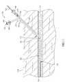
- FIG. 1is a partial cross-sectional view of an access site including a hemostatic device 100 outside the scope of the present invention, a guidewire 102, and a vessel or, more particularly, an artery 110 within subcutaneous tissue 112 under a skin surface 114.
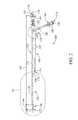
- FIG. 2is a perspective view of hemostatic device 100, and FIGS. 2A and 2B are detailed cut-away views of hemostatic device 100.
- the hemostatic device 100includes a locator device 120 having a distal end 122 and a proximal end 124. In the example, locator device 120 extends longitudinally approximately 20.0 centimeters (cm) from distal end 122 to proximal end 124.
- the locator device 120includes a sidewall 126 having a distal end opening 128, a proximal end opening 130, and a lumen 132 defined therebetween substantially aligned along a center axis 134.
- lumen 132is configured to channel a first fluid therethrough.
- the locator device 120includes a first section 136 and a second section 138.
- First section 136extends longitudinally a first distance 140 from distal end 122
- second section 138extends longitudinally a second distance 142 from proximal end 124.
- First distance 140is at least approximately 0.5 cm
- second distance 142is at most approximately 19.5 cm. More particularly, in the example, first distance 140 is approximately 1.0 cm, and second distance 142 is approximately 19.0 cm.
- the locator device 120is tapered at distal end 122 to facilitate traversing locator device 120 under skin surface 114 and through subcutaneous tissue 112.
- First section 136has a first outer diameter 144
- second section 138has a second outer diameter 146 that is larger than first outer diameter 144.
- Second outer diameter 146is approximately 2 millimeters (mm) or 6 French (Fr).
- second outer diameter 146is approximately 2.67 mm or 8 Fr.
- second outer diameter 146is approximately 3.33 mm or 10 Fr.
- the locator device 120is configured to receive guidewire 102 that extends longitudinally therethrough. More specifically, distal end opening 128, first section 136, second section 138, and proximal end opening 130 are sized such that guidewire 102 is capable of extending longitudinally through lumen 132 between proximal end opening 130 and distal end opening 128.
- the guidewire 102has an outer diameter of approximately 0.035 inches or 0.089 cm.
- the first section 136has a first inner diameter 148 that is approximately 0.089 cm
- second section 138has a second inner diameter 150 that is larger than approximately 0.089 cm. More specifically, second section 138 has a first subsection 152 that has first inner diameter 148 and a second subsection 154 that has second inner diameter 150.
- second inner diameter 150is approximately 0.059 inches or 0.150 cm. In another example, second inner diameter 150 is approximately 0.087 inches or 0.221 cm. In yet another example, second inner diameter 150 is approximately 0.113 inches or 0.287 cm.
- sidewall 126includes a distal opening 156 and a proximal opening 158 extending radially therethrough.
- Distal opening 156 and proximal opening 158are in fluid communication with lumen 132.
- the distal opening 156 and proximal opening 158are positioned within second section 138. More specifically, in the example, first subsection 152 extends longitudinally between first section 136 and distal opening 156, and second subsection extends longitudinally between distal opening 156 and proximal end 124.
- distal opening 156is positioned approximately 8.0 cm from distal end 122
- proximal opening 158is positioned approximately 1.0 cm from proximal end 124.
- the locator device 120includes a first device valve 160 positioned adjacent proximal opening 158.
- First device valve 160is actuatable between an open position and a closed position to selectively restrict access to a portion of locator device 120.
- proximal opening 158is at least partially exposed such that the fluid may flow into and/or out from lumen 132 through proximal opening 158.
- proximal opening 158is substantially covered by first device valve 160 such that a fluid is restricted from flowing into and/or out from lumen 132 through proximal opening 158.
- the first device valve 160is a sleeve that has an inner diameter 162 that is larger than second outer diameter 146 such that first device valve 160 is slidable about second section 138.
- the first device valve 160extends longitudinally approximately 1.0 cm about locator device 120.
- locator device 120includes a second device valve 164 positioned adjacent proximal end opening 130.
- Second device valve 164is actuatable between an open position and a closed position to selectively restrict access to a portion of locator device 120.
- proximal end opening 130In the open position, proximal end opening 130 is at least partially exposed such that guidewire 102 may extend through proximal end opening 130.
- proximal end opening 130In contrast, in the closed position, proximal end opening 130 is substantially covered by second device valve 164 such that a fluid is restricted from flowing into and/or out from lumen 132 through proximal end opening 130.
- second device valve 164is a manual-adjusting valve.
- the hemostatic device 100further includes an injection tube 170 having a distal end 172 and a proximal end 174.
- Injection tube 170extends longitudinally at least approximately 6.0 cm from distal end 172 to proximal end 174. More particularly, injection tube 170 extends longitudinally approximately 8.0 cm from distal end 172 to proximal end 174.
- Injection tube 170includes a sidewall 176 having a distal end opening 178, a proximal end opening 180, and a lumen 182 defined therebetween.
- distal end opening 178, proximal end opening 180, and lumen 182are substantially aligned along a center axis 184, and lumen 182 is configured to channel a second fluid therethrough.
- the injection tube 170is coupled to locator device 120 such that distal end 172 of injection tube 170 is positionable substantially adjacent artery 110. More specifically, when distal opening 156 of locator device 120 is positioned within artery 110, distal end 172 is positionable substantially adjacent, and outside, artery 110. Distal end 172 of injection tube 170 is positioned approximately 9.0 cm from distal end 122 of locator device 120 such that distal end 172 is positioned approximately 1.0 cm from distal opening 156. In one example, locator device 120 and injection tube 170 are substantially concentric.
- the injection tube 170includes a tube valve 186 positioned adjacent proximal end opening 180.
- Tube valve 186is actuatable between an open position and a closed position to selectively restrict access to a portion of tube valve 186.
- proximal end opening 180In the open position, proximal end opening 180 is at least partially exposed such that the fluid may flow into and/or out from lumen 182 through proximal end opening.
- proximal end opening 180is substantially covered by tube valve 186 such that a fluid is restricted from flowing into and/or out from lumen 182 through proximal end opening 180.
- the tube valve 186is a stop cock and includes a side port 188. The fluid may be injected into lumen 182 through side port 188.
- Injection tube 170includes an indicator 190 that indicates a length of locator device 120 and/or injection tube 170. More specifically, indicator 190 provides an indication of how much of injection tube 170 is under skin surface 114.
- the indicator 190includes a plurality of markings 192 that are spaced evenly along injection tube 170. More specifically, there is at least one marking 192 for each centimeter of injection tube 170.
- FIG. 3is a partial cross-sectional view of the access site including an alternative hemostatic device 200.
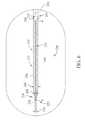
- FIG. 4is a perspective view of hemostatic device 200.
- hemostatic device 200includes a locator device 220, also shown in FIG. 5 , that is substantially similar to locator device 120 described in more detail above.
- locator device 220includes a distal end 222 and a proximal end 224. Distal end 222 is tapered to facilitate traversing locator device 220 under skin surface 114 and through subcutaneous tissue 112.
- locator device 220includes a sidewall 226 having a distal end opening 228, a proximal end opening 230, and a lumen 232 defined therebetween sized to channel the first fluid therethrough. More specifically, as shown in FIG. 6 , locator device 220 includes first section 236 having a first outer diameter 244, and a second section 238 having a second outer diameter 246 that is larger than first outer diameter 244. In one embodiment, second outer diameter 246 is approximately 0.099 inches or 0.251 cm for the 6 Fr system. In another embodiment, second outer diameter 246 is approximately 0.125 inches or 0.318 cm for the 8 Fr system. Alternatively, second outer diameter 246 may be any suitable width that enables locator device 220 to function as described herein.
- first section 236has a first inner diameter 248 that is approximately 0.889 mm
- second section 238has a second inner diameter 250 that is sized to enable an inner flow lumen to be defined around guidewire 102.
- second section 238has a first subsection 252 that has first inner diameter 248 and a second subsection 254 that has second inner diameter 250 that is larger than first inner diameter 248.
- first subsection 252extends longitudinally approximately 7.0 cm from distal end 222.
- second inner diameter 250is approximately 0.081 inches or 0.206 cm for the 6 Fr system.
- second inner diameter 250is approximately 0.107 inches or 0.272 cm for the 8 Fr system.
- second inner diameter 250may be any suitable width that enables locator device 220 to function as described herein.
- sidewall 226includes a distal opening 256 and a proximal opening 258 extending radially therethrough.
- Distal opening 256 and proximal opening 258are in fluid communication with lumen 232.
- distal opening 256 and proximal opening 258are positioned within second section 238. More specifically, in the exemplary embodiment, first subsection 252 extends longitudinally between first section 236 and distal opening 256, and second subsection extends longitudinally between distal opening 256 and proximal end 224.
- distal opening 256is positioned approximately 8.0 cm from distal end 222, and proximal opening 258 is positioned approximately 3.0 cm from proximal end 224.
- distal opening 256 and proximal opening 258may be positioned at any suitable location that enables locator device 220 to function as described herein.
- first device valve 160is positioned adjacent proximal opening 258.
- First device valve 160is actuatable between the open position and the closed position to selectively restrict access to at least a portion of locator device 220, as described in more detail above with respect to locator device 120.
- second device valve 164is positioned adjacent proximal end opening 230. Second device valve 164 is actuatable between the open position and the closed position to selectively restrict access to a portion of locator device 220, as described in more detail above with respect to locator device 120.
- Locator device 220includes a cap 261 coupleable to an injection tube 270, also shown in FIG. 7 , that is substantially similar to injection tube 170.
- injection tube 270has a distal end 272 and a proximal end 274.
- Injection tube 270is tapered at distal end 272 to facilitate traversing injection tube 270 under skin surface 114 and through subcutaneous tissue 112.
- Injection tube 270includes a sidewall 276 having a distal end opening 278, a proximal end opening 280, and a lumen 282 defined therebetween.
- distal end opening 278includes a distal valve 283 configured to receive locator device 220 such that locator device 220 and injection tube 270 are substantially coaxial. More specifically, in the exemplary embodiment, locator device 220 is advanceable through distal valve 283 such that injection tube 270 substantially houses at least a portion of locator device 220.
- locator device 220is advanced until a proximal valve 285 positioned at injection tube proximal end 274 is coupled to cap 261 such that injection tube distal end 272 may be positioned substantially adjacent distal opening 256.
- injection tube distal end 272is positionable approximately 9.0 cm from locator device distal end 222 and/or approximately 1.0 cm from locator device distal opening 256. As such, when locator device distal opening 256 is positioned within artery 110, injection tube distal end 272 is positioned substantially adjacent, and outside, artery 110.
- injection tube 270has a first inner diameter 287 adjacent distal end 272 that is substantially similar to locator device second outer diameter 246.
- first inner diameter 287is approximately 0.099 inches or 0.251 cm for the 6 Fr system.
- first inner diameter 287is approximately 0.125 inches or 0.318 cm for the 8 Fr system.
- injection tube 270has a second inner diameter 289 that is sized to channel the second fluid through lumen 282 about locator device 220.
- second inner diameter 289is wider than first inner diameter 287 or, more specifically, locator device second outer diameter 246 in the exemplary embodiment.
- second inner diameter 289is approximately 0.139 inches or 0.353 cm for the 6 Fr system.
- second inner diameter 289is approximately 0.165 inches or 0.419 cm for the 8 Fr system.
- side port 188extends from injection tube 270 and is communicatively coupled to lumen 282.
- Side port 188includes tube valve 186 that is actuatable between the open position and the closed position to selectively restrict access to a portion of tube valve 186, as described in more detail above with respect to injection tube 170.
- the second fluidis injectable into side port 188, through lumen 282, and discharged from a plurality of side openings 291 extending through sidewall 276.
- Side openings 291are spaced substantially evenly about a circumference of injection tube 270.
- side openings 289are positioned at each quadrant of sidewall 276.
- side openings 291are positioned adjacent distal opening 156. More specifically, side openings 291 are spaced between approximately 5.0 mm and 10.0 mm from a distal end of injection tube 270. As such, when distal opening 256 is positioned within artery 110, side openings 291 are positionable substantially adjacent, and outside, artery 110 to facilitate sealing the puncture of artery 110.
- FIG. 8is a flow chart illustrating a method 300 of using hemostatic device 100 and/or 200.
- hemostatic device 100 and/or 200is used for sealing a puncture of artery 110 within subcutaneous tissue 112 under a skin surface 114.
- a limited angiographyis performed 304 through the sheath to assess the puncture of artery 110 and to ensure that the sheath is positioned within artery 110.
- the guidewire 102is advanced 306 through the sheath to artery 110 such that a tip of guidewire 102 is positioned at least approximately 5.0 cm beyond the tip of the sheath. More particularly, guidewire 102 is advanced 306 to position the tip of guidewire 102 approximately 10.0 cm beyond the tip of the sheath. Manual pressure is applied 308 over the access site, and the sheath is withdrawn 310 from the access site over guidewire 102.
- Locator device 120 and/or 220is determined or selected 312 based on a size of the sheath. For example, in one example locator device 120 and/or 220 is selected 312 to have an outer diameter that is approximately the same as an outer diameter of the sheath.
- the 6 Fr systemmay be used with, without limitation, a sheath having a diameter between approximately 4 Fr and 6 Fr
- the 8 Fr systemmay be used with, without limitation, a sheath having a diameter between approximately 6 Fr and 8 Fr.
- locator device 120 and/or 220is advanced 314 into artery 110 until a first fluid is channeled through locator device 120 and/or 220. More specifically, locator device 120 and/or 220 is advanced 314 or slid along guidewire 102 under skin surface 114, through subcutaneous tissue 112, and to artery 110 until distal opening 156 and/or 256 is positioned within artery 110 and a fluid such as blood flows into distal opening 156 and/or 256, through lumen 132 and/or 232, and out from proximal opening 158 and/or 258. In the example, locator device 120 and/or 220 is advanced 314 under skin level for approximately 8.0 cm.
- Proximal opening 158 and/or 258provides a visual cue that distal opening 156 and/or 256 is within artery 110 when the blood flows through proximal opening 158 and/or 258.
- first device valve 160is actuated 316 to the closed position to restrict the blood from flowing out from proximal opening 158 and/or 258 and/or through lumen 132 and/or 232.
- guidewire 102is withdrawn 318 from artery 110 and/or locator device 120 and/or 220, and second device valve 164 is actuated 320 to the closed position to restrict the blood from flowing through proximal end opening 130 and/or through lumen 132 and/or 232.
- Injection tube distal end 172 and/or 272is positioned 322 substantially adjacent artery 110. More specifically, the relative positioning of locator device 120 and/or 220 and injection tube 170 and/or 270 enables injection tube distal end 172 and/or 272 to be positioned 322 substantially adjacent, and just outside, artery 110 when distal opening 156 and/or 256 is initially advanced within artery 110.
- a second fluid or, more particularly, a flowable gelatinis injected 324 around artery 110 and along a tract through subcutaneous tissue 112 between artery 110 and skin surface 114 through injection tube 170 and/or 270 to facilitate sealing the puncture of artery 110. More specifically, in the example, the flowable gelatin is prepared 326 and received within a syringe (not shown), and the syringe is coupled 328 to injection tube side port 188.
- hemostatic device 100 and/or 200may be systematically positioned within subcutaneous tissue 112 based on at least one length indicated by indicator 190 to enable the flowable gelatin to be systematically injected 324 through injection tube 170 and/or 270 at each position.
- indicator 190provides a visual cue that a length of injection tube 170 and/or 270 is under skin surface 114 and facilitates maintaining the length and/or systematically adjusting the length.
- side port 188may be rotated approximately 180° about center axis 134 to inject additional flowable gelatin through injection tube 170.
- hemostatic device 100 and/or 200is withdrawn 334 from artery 110 and/or subcutaneous tissue 112.
- direct, non-occlusive manual pressureis continuously applied 336 to the access site until hemostasis is achieved.
- the methods and systems described hereinrelate to medical devices and, more particularly, to a hemostatic device.
- the hemostatic device described hereinfacilitates sealing a puncture of a vessel. More particularly, the hemostatic device enables positioning an injection tube adjacent the vessel to inject a gelatin through the injection tube. As such, the hemostatic device facilitates reducing a time required for hemostasis and ambulation.
Landscapes
- Health & Medical Sciences (AREA)
- Surgery (AREA)
- Life Sciences & Earth Sciences (AREA)
- Medical Informatics (AREA)
- Nuclear Medicine, Radiotherapy & Molecular Imaging (AREA)
- Engineering & Computer Science (AREA)
- Biomedical Technology (AREA)
- Heart & Thoracic Surgery (AREA)
- Cardiology (AREA)
- Molecular Biology (AREA)
- Animal Behavior & Ethology (AREA)
- General Health & Medical Sciences (AREA)
- Public Health (AREA)
- Veterinary Medicine (AREA)
- Infusion, Injection, And Reservoir Apparatuses (AREA)
- Surgical Instruments (AREA)
Description
- The subject matter described herein relates generally to medical devices and, more particularly, to a hemostatic device.
- Catheter introducers are known to provide an access site to an artery for at least some medical procedures such as cardiac catheterizations or peripheral endovascular procedures. After such medical procedures are conducted, the catheter introducer is removed from the access site, leaving an arterial opening. Generally, excess blood loss endangers and/or traumatizes the patient. One known method of controlling blood loss is through direct manual pressure over the access site.
- A device for controlling such blood loss is disclosed in
U.S. Pat. Pub. No. 2010/312273 , which describes a combined vascular and closure sheath. The closure sheath is disposed circumferentially around an exterior surface of the vascular sheath, thereby forming a closure sheath lumen between the exterior surface of the vascular sheath and an interior surface of the closure sheath. After the vascular sheath is inserted into a vessel, the closure sheath is configured to eject a coagulation protein to the vessel puncture site through a plurality of apertures disposed upon a distal end of the closure sheath. A radiopaque or ultrasound marker on the vascular sheath must be monitored to ensure proper placement of the apertures prior to applying the coagulation protein. - Another device for controlling such blood loss is disclosed in
U.S. Pat. Pub. No. 2004/176801 , which describes a closure device that includes a plugging catheter extending through a central lumen. The central lumen includes an exit port adjacent its distal end, and is connected to a precursor entrance port, through which a closure composition precursor is supplied. In order to determine when the exit port is positioned outside the vessel, the portion of the plugging catheter that extends from the central lumen includes several angularly spaced pressure ports, each in communication with a respective lumen that extends within the plugging catheter. - Another device for controlling such blood loss is disclosed in
U.S. Pat. No. 6,500,152 , which describes a working cannula that extends axially through a sealing cannula, such that a portion of the sealing cannula projects downward out of the sealing cannula. At least one inlet opening is provided in the working cannula near a proximal end of the sealing cannula. A threaded coupling piece is operable to extend and retract the working cannula relative to the sealing cannula, such that the inlet openings are alternately exposed outside, or sealed within, the sealing cannula. In addition, a hollow space is disposed concentrically between the working cannula and the sealing cannula, with exit openings disposed near the proximal end of the sealing cannula. When the working cannula is inserted into an artery and the inlet openings are exposed, blood rises into the working cannula and flows out at a control connection piece coupled to the working cannula, thus indicating that the exit openings of the hollow space are positioned outside the artery. The coupling piece is then rotated by a lever such that the inlet openings of the working cannula are drawn into sealing cannula, and an adhesive is injected into the hollow space for ejection at the exit openings near the artery. - In accordance with the present invention, there is provided a hemostatic device according to
claim 1. FIG. 1 is a partial cross-sectional view of an access site including a hemostatic device;FIG. 2 is a perspective view of the hemostatic device shown inFIG. 1 ;FIGS. 2A and 2B are cut-away views of the hemostatic device shown inFIG. 1 ;FIG. 3 is a partial cross-sectional view of an access site including an alternative hemostatic device;FIG. 4 is a perspective view of the hemostatic device shown inFIG. 3 ;FIG. 5 is a perspective view of a locator device that may be used with the hemostatic device shown inFIG. 3 ;FIG. 6 is a cut-away view of the locator device shown inFIG. 5 ;FIG. 7 is a perspective view of an injection tube that may be used with the hemostatic device shown inFIG. 3 ; andFIG. 8 is a flow chart illustrating amethod using the hemostatic device shown inFIG. 1 and/orFIG. 3 .- The methods and apparatus described herein relate to medical devices and, more particularly, to a hemostatic device. The hemostatic device described herein facilitates sealing a puncture of a vessel. More particularly, the hemostatic device enables positioning an injection tube adjacent the vessel to inject a gelatin through the injection tube. As such, the hemostatic device facilitates reducing a time required for hemostasis and ambulation.
FIG. 1 is a partial cross-sectional view of an access site including ahemostatic device 100 outside the scope of the present invention, aguidewire 102, and a vessel or, more particularly, anartery 110 withinsubcutaneous tissue 112 under askin surface 114.FIG. 2 is a perspective view ofhemostatic device 100, andFIGS. 2A and 2B are detailed cut-away views ofhemostatic device 100. Thehemostatic device 100 includes alocator device 120 having adistal end 122 and aproximal end 124. In the example,locator device 120 extends longitudinally approximately 20.0 centimeters (cm) fromdistal end 122 toproximal end 124.- The
locator device 120 includes asidewall 126 having a distal end opening 128, a proximal end opening 130, and alumen 132 defined therebetween substantially aligned along acenter axis 134. In the example,lumen 132 is configured to channel a first fluid therethrough. - The
locator device 120 includes afirst section 136 and asecond section 138.First section 136 extends longitudinally afirst distance 140 fromdistal end 122, andsecond section 138 extends longitudinally asecond distance 142 fromproximal end 124.First distance 140 is at least approximately 0.5 cm, andsecond distance 142 is at most approximately 19.5 cm. More particularly, in the example,first distance 140 is approximately 1.0 cm, andsecond distance 142 is approximately 19.0 cm. - The
locator device 120 is tapered atdistal end 122 to facilitate traversinglocator device 120 underskin surface 114 and throughsubcutaneous tissue 112.First section 136 has a firstouter diameter 144, andsecond section 138 has a secondouter diameter 146 that is larger than firstouter diameter 144. Secondouter diameter 146 is approximately 2 millimeters (mm) or 6 French (Fr). In another example, secondouter diameter 146 is approximately 2.67 mm or 8 Fr. In yet another example, secondouter diameter 146 is approximately 3.33 mm or 10 Fr. - The
locator device 120 is configured to receiveguidewire 102 that extends longitudinally therethrough. More specifically,distal end opening 128,first section 136,second section 138, and proximal end opening 130 are sized such thatguidewire 102 is capable of extending longitudinally throughlumen 132 between proximal end opening 130 anddistal end opening 128. Theguidewire 102 has an outer diameter of approximately 0.035 inches or 0.089 cm. - The
first section 136 has a firstinner diameter 148 that is approximately 0.089 cm, andsecond section 138 has a secondinner diameter 150 that is larger than approximately 0.089 cm. More specifically,second section 138 has afirst subsection 152 that has firstinner diameter 148 and asecond subsection 154 that has secondinner diameter 150. In one example, secondinner diameter 150 is approximately 0.059 inches or 0.150 cm. In another example, secondinner diameter 150 is approximately 0.087 inches or 0.221 cm. In yet another example, secondinner diameter 150 is approximately 0.113 inches or 0.287 cm. - As shown in
FIG. 1 ,sidewall 126 includes adistal opening 156 and aproximal opening 158 extending radially therethrough.Distal opening 156 andproximal opening 158 are in fluid communication withlumen 132. Thedistal opening 156 andproximal opening 158 are positioned withinsecond section 138. More specifically, in the example,first subsection 152 extends longitudinally betweenfirst section 136 anddistal opening 156, and second subsection extends longitudinally betweendistal opening 156 andproximal end 124. In the example,distal opening 156 is positioned approximately 8.0 cm fromdistal end 122, andproximal opening 158 is positioned approximately 1.0 cm fromproximal end 124. - The
locator device 120 includes afirst device valve 160 positioned adjacentproximal opening 158.First device valve 160 is actuatable between an open position and a closed position to selectively restrict access to a portion oflocator device 120. In the open position,proximal opening 158 is at least partially exposed such that the fluid may flow into and/or out fromlumen 132 throughproximal opening 158. In contrast, in the closed position,proximal opening 158 is substantially covered byfirst device valve 160 such that a fluid is restricted from flowing into and/or out fromlumen 132 throughproximal opening 158. Thefirst device valve 160 is a sleeve that has aninner diameter 162 that is larger than secondouter diameter 146 such thatfirst device valve 160 is slidable aboutsecond section 138. Thefirst device valve 160 extends longitudinally approximately 1.0 cm aboutlocator device 120. - Additionally,
locator device 120 includes asecond device valve 164 positioned adjacentproximal end opening 130.Second device valve 164 is actuatable between an open position and a closed position to selectively restrict access to a portion oflocator device 120. In the open position,proximal end opening 130 is at least partially exposed such thatguidewire 102 may extend throughproximal end opening 130. In contrast, in the closed position,proximal end opening 130 is substantially covered bysecond device valve 164 such that a fluid is restricted from flowing into and/or out fromlumen 132 throughproximal end opening 130. In the example,second device valve 164 is a manual-adjusting valve. - The
hemostatic device 100 further includes aninjection tube 170 having adistal end 172 and aproximal end 174.Injection tube 170 extends longitudinally at least approximately 6.0 cm fromdistal end 172 toproximal end 174. More particularly,injection tube 170 extends longitudinally approximately 8.0 cm fromdistal end 172 toproximal end 174.Injection tube 170 includes asidewall 176 having adistal end opening 178, aproximal end opening 180, and alumen 182 defined therebetween. In the example,distal end opening 178,proximal end opening 180, andlumen 182 are substantially aligned along acenter axis 184, andlumen 182 is configured to channel a second fluid therethrough. - The
injection tube 170 is coupled tolocator device 120 such thatdistal end 172 ofinjection tube 170 is positionable substantiallyadjacent artery 110. More specifically, whendistal opening 156 oflocator device 120 is positioned withinartery 110,distal end 172 is positionable substantially adjacent, and outside,artery 110.Distal end 172 ofinjection tube 170 is positioned approximately 9.0 cm fromdistal end 122 oflocator device 120 such thatdistal end 172 is positioned approximately 1.0 cm fromdistal opening 156. In one example,locator device 120 andinjection tube 170 are substantially concentric. - The
injection tube 170 includes atube valve 186 positioned adjacentproximal end opening 180.Tube valve 186 is actuatable between an open position and a closed position to selectively restrict access to a portion oftube valve 186. In the open position,proximal end opening 180 is at least partially exposed such that the fluid may flow into and/or out fromlumen 182 through proximal end opening. In contrast, in the closed position,proximal end opening 180 is substantially covered bytube valve 186 such that a fluid is restricted from flowing into and/or out fromlumen 182 throughproximal end opening 180. Thetube valve 186 is a stop cock and includes aside port 188. The fluid may be injected intolumen 182 throughside port 188. Injection tube 170 includes anindicator 190 that indicates a length oflocator device 120 and/orinjection tube 170. More specifically,indicator 190 provides an indication of how much ofinjection tube 170 is underskin surface 114. Theindicator 190 includes a plurality ofmarkings 192 that are spaced evenly alonginjection tube 170. More specifically, there is at least one marking 192 for each centimeter ofinjection tube 170.FIG. 3 is a partial cross-sectional view of the access site including an alternativehemostatic device 200.FIG. 4 is a perspective view ofhemostatic device 200. In the exemplary embodiment,hemostatic device 200 includes alocator device 220, also shown inFIG. 5 , that is substantially similar tolocator device 120 described in more detail above. In the exemplary embodiment,locator device 220 includes adistal end 222 and aproximal end 224.Distal end 222 is tapered to facilitatetraversing locator device 220 underskin surface 114 and throughsubcutaneous tissue 112.- In the exemplary embodiment,
locator device 220 includes asidewall 226 having adistal end opening 228, aproximal end opening 230, and alumen 232 defined therebetween sized to channel the first fluid therethrough. More specifically, as shown inFIG. 6 ,locator device 220 includesfirst section 236 having a firstouter diameter 244, and asecond section 238 having a secondouter diameter 246 that is larger than firstouter diameter 244. In one embodiment, secondouter diameter 246 is approximately 0.099 inches or 0.251 cm for the 6 Fr system. In another embodiment, secondouter diameter 246 is approximately 0.125 inches or 0.318 cm for the 8 Fr system. Alternatively, secondouter diameter 246 may be any suitable width that enableslocator device 220 to function as described herein. - Moreover, as shown in
FIG. 6 ,first section 236 has a firstinner diameter 248 that is approximately 0.889 mm, andsecond section 238 has a secondinner diameter 250 that is sized to enable an inner flow lumen to be defined aroundguidewire 102. More specifically, in the exemplary embodiment,second section 238 has afirst subsection 252 that has firstinner diameter 248 and asecond subsection 254 that has secondinner diameter 250 that is larger than firstinner diameter 248. In the exemplary embodiment,first subsection 252 extends longitudinally approximately 7.0 cm fromdistal end 222. In one embodiment, secondinner diameter 250 is approximately 0.081 inches or 0.206 cm for the 6 Fr system. In another embodiment, secondinner diameter 250 is approximately 0.107 inches or 0.272 cm for the 8 Fr system. Alternatively, secondinner diameter 250 may be any suitable width that enableslocator device 220 to function as described herein. - In the exemplary embodiment,
sidewall 226 includes adistal opening 256 and aproximal opening 258 extending radially therethrough.Distal opening 256 andproximal opening 258 are in fluid communication withlumen 232. In the exemplary embodiment,distal opening 256 andproximal opening 258 are positioned withinsecond section 238. More specifically, in the exemplary embodiment,first subsection 252 extends longitudinally betweenfirst section 236 anddistal opening 256, and second subsection extends longitudinally betweendistal opening 256 andproximal end 224. In the exemplary embodiment,distal opening 256 is positioned approximately 8.0 cm fromdistal end 222, andproximal opening 258 is positioned approximately 3.0 cm fromproximal end 224. Alternatively,distal opening 256 andproximal opening 258 may be positioned at any suitable location that enableslocator device 220 to function as described herein. - In the exemplary embodiment,
first device valve 160 is positioned adjacentproximal opening 258.First device valve 160 is actuatable between the open position and the closed position to selectively restrict access to at least a portion oflocator device 220, as described in more detail above with respect tolocator device 120. Moreover, in the exemplary embodiment,second device valve 164 is positioned adjacentproximal end opening 230.Second device valve 164 is actuatable between the open position and the closed position to selectively restrict access to a portion oflocator device 220, as described in more detail above with respect tolocator device 120. Locator device 220 includes acap 261 coupleable to aninjection tube 270, also shown inFIG. 7 , that is substantially similar toinjection tube 170. In the exemplary embodiment,injection tube 270 has adistal end 272 and aproximal end 274.Injection tube 270 is tapered atdistal end 272 to facilitate traversinginjection tube 270 underskin surface 114 and throughsubcutaneous tissue 112.Injection tube 270 includes asidewall 276 having adistal end opening 278, aproximal end opening 280, and alumen 282 defined therebetween. In the exemplary embodiment,distal end opening 278 includes adistal valve 283 configured to receivelocator device 220 such thatlocator device 220 andinjection tube 270 are substantially coaxial. More specifically, in the exemplary embodiment,locator device 220 is advanceable throughdistal valve 283 such thatinjection tube 270 substantially houses at least a portion oflocator device 220. In the exemplary embodiment,locator device 220 is advanced until aproximal valve 285 positioned at injection tubeproximal end 274 is coupled to cap 261 such that injection tubedistal end 272 may be positioned substantially adjacentdistal opening 256. In the exemplary embodiment, injection tubedistal end 272 is positionable approximately 9.0 cm from locator devicedistal end 222 and/or approximately 1.0 cm from locator devicedistal opening 256. As such, when locator devicedistal opening 256 is positioned withinartery 110, injection tubedistal end 272 is positioned substantially adjacent, and outside,artery 110.- In the exemplary embodiment,
injection tube 270 has a first inner diameter 287 adjacentdistal end 272 that is substantially similar to locator device secondouter diameter 246. In one embodiment, first inner diameter 287 is approximately 0.099 inches or 0.251 cm for the 6 Fr system. In another embodiment, first inner diameter 287 is approximately 0.125 inches or 0.318 cm for the 8 Fr system. In the exemplary embodiment,injection tube 270 has a second inner diameter 289 that is sized to channel the second fluid throughlumen 282 aboutlocator device 220. As such, second inner diameter 289 is wider than first inner diameter 287 or, more specifically, locator device secondouter diameter 246 in the exemplary embodiment. In one embodiment, second inner diameter 289 is approximately 0.139 inches or 0.353 cm for the 6 Fr system. In another embodiment, second inner diameter 289 is approximately 0.165 inches or 0.419 cm for the 8 Fr system. - In the exemplary embodiment,
side port 188 extends frominjection tube 270 and is communicatively coupled tolumen 282.Side port 188 includestube valve 186 that is actuatable between the open position and the closed position to selectively restrict access to a portion oftube valve 186, as described in more detail above with respect toinjection tube 170. The second fluid is injectable intoside port 188, throughlumen 282, and discharged from a plurality ofside openings 291 extending throughsidewall 276.Side openings 291 are spaced substantially evenly about a circumference ofinjection tube 270. For example, in one embodiment, side openings 289 are positioned at each quadrant ofsidewall 276. - In the exemplary embodiment,
side openings 291 are positioned adjacentdistal opening 156. More specifically,side openings 291 are spaced between approximately 5.0 mm and 10.0 mm from a distal end ofinjection tube 270. As such, whendistal opening 256 is positioned withinartery 110,side openings 291 are positionable substantially adjacent, and outside,artery 110 to facilitate sealing the puncture ofartery 110. FIG. 8 is a flow chart illustrating amethod 300 of usinghemostatic device 100 and/or 200. During operation,hemostatic device 100 and/or 200 is used for sealing a puncture ofartery 110 withinsubcutaneous tissue 112 under askin surface 114.- A sheath (not shown) used during a medical procedure, such as a cardiac catheterization or a peripheral endovascular procedure, is withdrawn 302 such that a tip of the sheath is positioned approximately 10.0 cm from the access site and the sheath is free of at least some devices. A limited angiography is performed 304 through the sheath to assess the puncture of
artery 110 and to ensure that the sheath is positioned withinartery 110. - The
guidewire 102 is advanced 306 through the sheath toartery 110 such that a tip ofguidewire 102 is positioned at least approximately 5.0 cm beyond the tip of the sheath. More particularly, guidewire 102 is advanced 306 to position the tip ofguidewire 102 approximately 10.0 cm beyond the tip of the sheath. Manual pressure is applied 308 over the access site, and the sheath is withdrawn 310 from the access site overguidewire 102.Locator device 120 and/or 220 is determined or selected 312 based on a size of the sheath. For example, in oneexample locator device 120 and/or 220 is selected 312 to have an outer diameter that is approximately the same as an outer diameter of the sheath. More specifically, in such an example, the 6 Fr system may be used with,
without limitation, a sheath having a diameter between approximately 4 Fr and 6 Fr, and the 8 Fr system may be used with, without limitation, a sheath having a diameter between approximately 6 Fr and 8 Fr. - The
locator device 120 and/or 220 is advanced 314 intoartery 110 until a first fluid is channeled throughlocator device 120 and/or 220. More specifically,locator device 120 and/or 220 is advanced 314 or slid alongguidewire 102 underskin surface 114, throughsubcutaneous tissue 112, and toartery 110 untildistal opening 156 and/or 256 is positioned withinartery 110 and a fluid such as blood flows intodistal opening 156 and/or 256, throughlumen 132 and/or 232, and out fromproximal opening 158 and/or 258. In the example,locator device 120 and/or 220 is advanced 314 under skin level for approximately 8.0 cm. Proximal opening 158 and/or 258 provides a visual cue thatdistal opening 156 and/or 256 is withinartery 110 when the blood flows throughproximal opening 158 and/or 258. To reduce an amount of blood that refluxes throughproximal opening 158 and/or 258,first device valve 160 is actuated 316 to the closed position to restrict the blood from flowing out fromproximal opening 158 and/or 258 and/or throughlumen 132 and/or 232. Moreover, guidewire 102 is withdrawn 318 fromartery 110 and/orlocator device 120 and/or 220, andsecond device valve 164 is actuated 320 to the closed position to restrict the blood from flowing throughproximal end opening 130 and/or throughlumen 132 and/or 232.- Injection tube
distal end 172 and/or 272 is positioned 322 substantiallyadjacent artery 110. More specifically, the relative positioning oflocator device 120 and/or 220 andinjection tube 170 and/or 270 enables injection tubedistal end 172 and/or 272 to be positioned 322 substantially adjacent, and just outside,artery 110 whendistal opening 156 and/or 256 is initially advanced withinartery 110. - A second fluid or, more particularly, a flowable gelatin is injected 324 around
artery 110 and along a tract throughsubcutaneous tissue 112 betweenartery 110 andskin surface 114 throughinjection tube 170 and/or 270 to facilitate sealing the puncture ofartery 110. More specifically, in the example, the flowable gelatin is prepared 326 and received within a syringe (not shown), and the syringe is coupled 328 to injectiontube side port 188. - The flowable gelatin discharged from
side openings 291 to facilitate sealing the access site. The injection process may be repeated ashemostatic device 100 and/or 200 is withdrawn 334 from artery 110 a length at a time untilhemostatic device 100 and/or 200 is substantially withdrawn fromsubcutaneous tissue 112. More specifically, in such an arrangement,hemostatic device 100 and/or 200 may be systematically positioned withinsubcutaneous tissue 112 based on at least one length indicated byindicator 190 to enable the flowable gelatin to be systematically injected 324 throughinjection tube 170 and/or 270 at each position. In one example,indicator 190 provides a visual cue that a length ofinjection tube 170 and/or 270 is underskin surface 114 and facilitates maintaining the length and/or systematically adjusting the length. Additionally or alternatively,side port 188 may be rotated approximately 180° aboutcenter axis 134 to inject additional flowable gelatin throughinjection tube 170. - When injection tube
distal end 172 and/or 272 is substantiallyadjacent skin surface 114,hemostatic device 100 and/or 200 is withdrawn 334 fromartery 110 and/orsubcutaneous tissue 112. In the example, direct, non-occlusive manual pressure is continuously applied 336 to the access site until hemostasis is achieved. - The methods and systems described herein relate to medical devices and, more particularly, to a hemostatic device. The hemostatic device described herein facilitates sealing a puncture of a vessel. More particularly, the hemostatic device enables positioning an injection tube adjacent the vessel to inject a gelatin through the injection tube. As such, the hemostatic device facilitates reducing a time required for hemostasis and ambulation.
Claims (8)
- A hemostatic device (200) for sealing a puncture of a vessel (110), said hemostatic device comprising:a locator device (220) comprising a first sidewall (226) and including a distal opening (256) extending through the first sidewall and configured to channel a first fluid through the distalopening and through a first lumen (232) defined by an inner surface of the first sidewall and a proximal opening (258) extending through the first sidewall, the distal opening in fluid communication with the proximal opening, wherein a distal end (272) of the injection tube is positionable substantially adjacent the vessel when the first fluid is channeled from the distal opening to the proximal opening; andan injection tube (270) comprising a second sidewall (276) housing at least a portion of the locator device, the injection tube aligned substantially coaxially with the locator device, the injection tube including at least one discharge port (291) extending through the second sidewall and configured to channel a second fluid through a second lumen (282) defined by an outer surface of the first sidewall and an inner surface of the second sidewall and discharge the second fluid from the at least one discharge port (291);characterised in that the locator device further comprises:a device valve (160) actuatable between an open position and a closed position to selectively restrict access to the first lumen (232), wherein the device valve restricts blood from flowing out from the proximal opening (258) in the closed position.
- A hemostatic device in accordance with claim 1, wherein the first sidewall (226) includes a first section (236) having a first inner diameter (248) and a second section (238) having a second inner diameter (250) that is different from the first inner diameter and has an outer diameter that tapers toward a distal end (222) of the locator device.
- A hemostatic device in accordance with claim 1, wherein the locator device further comprises a second device valve (164) that is actuatable to selectively restrict access to the first lumen.
- A hemostatic device in accordance with claim 1, wherein the locator device further comprises a cap (261) coupled to a proximal end of the injection tube.
- A hemostatic device in accordance with claim 1, wherein the second sidewall (276) includes a first section having a first inner diameter (287) and a second section having a second inner diameter (289) that is different from the first inner diameter, and has an outer diameter that tapers towards a distal end (272) of the injection tube.
- A hemostatic device in accordance with claim 1, wherein the injection tube further comprises a tube valve (186) that is actuatable to selectively provide access to a portion of the injection tube.
- A hemostatic device in accordance with claim 1, wherein at least one of the locator device and the injection tube further comprises an indicator (190) that indicates a length of at least one of the locator device and the injection tube.
- A hemostatic device in accordance with claim 1, wherein the injection tube includes a plurality of discharge ports (291) extending through the second sidewall and spaced substantially evenly about a circumference of the injection tube.
Applications Claiming Priority (3)
| Application Number | Priority Date | Filing Date | Title |
|---|---|---|---|
| US12/762,886US9179900B2 (en) | 2009-12-08 | 2010-04-19 | Hemostatic device and its methods of use |
| US13/086,712US8876862B2 (en) | 2011-04-14 | 2011-04-14 | Hemostatic device and its methods of use |
| PCT/US2011/032490WO2011133395A1 (en) | 2010-04-19 | 2011-04-14 | A hemostatic device and its methods of use |
Publications (3)
| Publication Number | Publication Date |
|---|---|
| EP2560556A1 EP2560556A1 (en) | 2013-02-27 |
| EP2560556A4 EP2560556A4 (en) | 2014-10-15 |
| EP2560556B1true EP2560556B1 (en) | 2016-10-12 |
Family
ID=44834460
Family Applications (1)
| Application Number | Title | Priority Date | Filing Date |
|---|---|---|---|
| EP11772458.3ANot-in-forceEP2560556B1 (en) | 2010-04-19 | 2011-04-14 | A hemostatic device |
Country Status (5)
| Country | Link |
|---|---|
| US (1) | US8876862B2 (en) |
| EP (1) | EP2560556B1 (en) |
| AU (1) | AU2011243001B2 (en) |
| CA (1) | CA2794606A1 (en) |
| WO (1) | WO2011133395A1 (en) |
Families Citing this family (7)
| Publication number | Priority date | Publication date | Assignee | Title |
|---|---|---|---|---|
| US9993236B2 (en) | 2009-12-08 | 2018-06-12 | Phillips Medical, LLC | Hemostatic device and its methods of use |
| US9468428B2 (en) | 2012-06-13 | 2016-10-18 | Phillips Medical Llc | Hemostatic device and its methods of use |
| US10085730B2 (en) | 2013-07-12 | 2018-10-02 | Phillips Medical, LLC | Hemostatic device and its methods of use |
| US9839416B2 (en)* | 2013-07-12 | 2017-12-12 | Phillips Medical, LLC | Hemostatic device and its methods of use |
| US9782549B2 (en) | 2014-10-22 | 2017-10-10 | Ethicon, Inc. | Distance indicators for medicinal spray devices |
| US11478248B2 (en)* | 2017-05-12 | 2022-10-25 | National University Of Ireland, Galway | Percutaneous vascular surgical system and method |
| EP4090271B1 (en)* | 2020-01-16 | 2025-04-09 | Stratos Medical Limited | A medical device |
Family Cites Families (66)
| Publication number | Priority date | Publication date | Assignee | Title |
|---|---|---|---|---|
| US4738658A (en) | 1986-09-19 | 1988-04-19 | Aries Medical Incorporated | Tapered hemostatic device for use in conjunction with a catheter for alleviating blood leakage and method for using same |
| USRE34866E (en) | 1987-02-17 | 1995-02-21 | Kensey Nash Corporation | Device for sealing percutaneous puncture in a vessel |
| US4890612A (en) | 1987-02-17 | 1990-01-02 | Kensey Nash Corporation | Device for sealing percutaneous puncture in a vessel |
| US4850960A (en) | 1987-07-08 | 1989-07-25 | Joseph Grayzel | Diagonally tapered, bevelled tip introducing catheter and sheath and method for insertion |
| US4895564A (en) | 1988-06-08 | 1990-01-23 | Farrell Edward M | Percutaneous femoral bypass system |
| US4929246A (en) | 1988-10-27 | 1990-05-29 | C. R. Bard, Inc. | Method for closing and sealing an artery after removing a catheter |
| US5061274A (en) | 1989-12-04 | 1991-10-29 | Kensey Nash Corporation | Plug device for sealing openings and method of use |
| US5391183A (en) | 1990-09-21 | 1995-02-21 | Datascope Investment Corp | Device and method sealing puncture wounds |
| US5108421A (en) | 1990-10-01 | 1992-04-28 | Quinton Instrument Company | Insertion assembly and method of inserting a vessel plug into the body of a patient |
| US6325789B1 (en) | 1990-12-27 | 2001-12-04 | Datascope Investment Corporation | Device and method for sealing puncture wounds |
| US5290310A (en) | 1991-10-30 | 1994-03-01 | Howmedica, Inc. | Hemostatic implant introducer |
| US5676689A (en) | 1991-11-08 | 1997-10-14 | Kensey Nash Corporation | Hemostatic puncture closure system including vessel location device and method of use |
| US5222974A (en) | 1991-11-08 | 1993-06-29 | Kensey Nash Corporation | Hemostatic puncture closure system and method of use |
| US5282827A (en) | 1991-11-08 | 1994-02-01 | Kensey Nash Corporation | Hemostatic puncture closure system and method of use |
| US6056768A (en) | 1992-01-07 | 2000-05-02 | Cates; Christopher U. | Blood vessel sealing system |
| US6699261B1 (en) | 1992-01-07 | 2004-03-02 | Cch Associates, Inc. | Blood vessel sealing system |
| US5326350A (en) | 1992-05-11 | 1994-07-05 | Li Shu Tung | Soft tissue closure systems |
| US5443481A (en) | 1992-07-27 | 1995-08-22 | Lee; Benjamin I. | Methods and device for percutaneous sealing of arterial puncture sites |
| US5306254A (en) | 1992-10-01 | 1994-04-26 | Kensey Nash Corporation | Vessel position locating device and method of use |
| US5415657A (en) | 1992-10-13 | 1995-05-16 | Taymor-Luria; Howard | Percutaneous vascular sealing method |
| US5951583A (en) | 1993-05-25 | 1999-09-14 | Vascular Solutions, Inc. | Thrombin and collagen procoagulant and process for making the same |
| US5431639A (en)* | 1993-08-12 | 1995-07-11 | Boston Scientific Corporation | Treating wounds caused by medical procedures |
| NL9301526A (en) | 1993-09-03 | 1995-04-03 | Cordis Europ | Device for hemostasis treatment after catheter surgery. |
| US5843124A (en) | 1993-09-28 | 1998-12-01 | Hemodynamics, Inc. | Surface opening adhesive sealer |
| US5653730A (en) | 1993-09-28 | 1997-08-05 | Hemodynamics, Inc. | Surface opening adhesive sealer |
| US5437292A (en) | 1993-11-19 | 1995-08-01 | Bioseal, Llc | Method for sealing blood vessel puncture sites |
| US6302898B1 (en) | 1994-06-24 | 2001-10-16 | Advanced Closure Systems, Inc. | Devices for sealing punctures in body vessels |
| US5766157A (en) | 1995-03-17 | 1998-06-16 | Tilton, Jr.; Eugene B. | Instrumentation for surgical endoscopic insertion and application of liquid and gel material |
| US6071300A (en) | 1995-09-15 | 2000-06-06 | Sub-Q Inc. | Apparatus and method for percutaneous sealing of blood vessel punctures |
| US6162192A (en) | 1998-05-01 | 2000-12-19 | Sub Q, Inc. | System and method for facilitating hemostasis of blood vessel punctures with absorbable sponge |
| US5645566A (en) | 1995-09-15 | 1997-07-08 | Sub Q Inc. | Apparatus and method for percutaneous sealing of blood vessel punctures |
| US6743248B2 (en) | 1996-12-18 | 2004-06-01 | Neomend, Inc. | Pretreatment method for enhancing tissue adhesion |
| US5782861A (en) | 1996-12-23 | 1998-07-21 | Sub Q Inc. | Percutaneous hemostasis device |
| US6045570A (en) | 1997-02-11 | 2000-04-04 | Biointerventional Corporation | Biological sealant mixture and system for use in percutaneous occlusion of puncture sites and tracts in the human body and method |
| US6371975B2 (en) | 1998-11-06 | 2002-04-16 | Neomend, Inc. | Compositions, systems, and methods for creating in situ, chemically cross-linked, mechanical barriers |
| US20040176801A1 (en) | 1997-03-12 | 2004-09-09 | Neomend, Inc. | Pretreatment method for enhancing tissue adhesion |
| US5868762A (en) | 1997-09-25 | 1999-02-09 | Sub-Q, Inc. | Percutaneous hemostatic suturing device and method |
| US6610026B2 (en) | 1998-05-01 | 2003-08-26 | Sub-Q, Inc. | Method of hydrating a sponge material for delivery to a body |
| US7625352B1 (en) | 1998-05-01 | 2009-12-01 | Sub-Q, Inc. | Depth and puncture control for system for hemostasis of blood vessel |
| US6315753B1 (en) | 1998-05-01 | 2001-11-13 | Sub-Q, Inc. | System and method for facilitating hemostasis of blood vessel punctures with absorbable sponge |
| JP4087565B2 (en) | 1998-07-02 | 2008-05-21 | バクスター・ヘルスケヤー・ソシエテ・アノニム | Device for introducing fibrin adhesive into perforation guide |
| US6296657B1 (en) | 1998-10-07 | 2001-10-02 | Gregory G. Brucker | Vascular sealing device and method |
| US6830756B2 (en) | 1998-11-06 | 2004-12-14 | Neomend, Inc. | Systems, methods, and compositions for achieving closure of vascular puncture sites |
| US7279001B2 (en) | 1998-11-06 | 2007-10-09 | Neomend, Inc. | Systems, methods, and compositions for achieving closure of vascular puncture sites |
| JP4271375B2 (en) | 1999-02-10 | 2009-06-03 | サブ−キュー・インコーポレーテッド | Device and method for facilitating hemostasis in a biopsy duct |
| US6984219B2 (en)* | 1999-09-23 | 2006-01-10 | Mark Ashby | Depth and puncture control for blood vessel hemostasis system |
| US6547806B1 (en) | 2000-02-04 | 2003-04-15 | Ni Ding | Vascular sealing device and method of use |
| US7201725B1 (en) | 2000-09-25 | 2007-04-10 | Sub-Q, Inc. | Device and method for determining a depth of an incision |
| US20090143808A1 (en) | 2001-04-24 | 2009-06-04 | Houser Russell A | Guided Tissue Cutting Device, Method of Use and Kits Therefor |
| US7008440B2 (en) | 2001-11-08 | 2006-03-07 | Sub-Q, Inc. | System and method for delivering hemostasis promoting material to a blood vessel puncture site by fluid pressure |
| US7029489B1 (en) | 2001-05-18 | 2006-04-18 | Sub-Q, Inc. | System and method for delivering hemostasis promoting material to a blood vessel puncture site |
| US6863680B2 (en) | 2001-11-08 | 2005-03-08 | Sub-Q, Inc. | System and method for delivering hemostasis promoting material to a blood vessel puncture site by fluid pressure |
| US20060004408A1 (en) | 2001-06-08 | 2006-01-05 | Morris Edward J | Method and apparatus for sealing access |
| US7037322B1 (en)* | 2001-11-08 | 2006-05-02 | Sub-Q, Inc. | System and method for delivering hemostasis promoting material to a blood vessel puncture with a staging tube |
| US6953465B2 (en) | 2002-03-25 | 2005-10-11 | Concentric Medical, Inc. | Containers and methods for delivering vaso-occluding filaments and particles |
| US20040102730A1 (en) | 2002-10-22 | 2004-05-27 | Davis Thomas P. | System and method for facilitating hemostasis of blood vessel punctures with absorbable sponge |
| US7455680B1 (en) | 2002-11-04 | 2008-11-25 | Boston Scientific Scimed, Inc. | Apparatus and method for inhibiting blood loss |
| US8262693B2 (en) | 2004-11-05 | 2012-09-11 | Accessclosure, Inc. | Apparatus and methods for sealing a vascular puncture |
| WO2006074044A2 (en)* | 2004-12-30 | 2006-07-13 | Neomend, Inc. | Method and apparatus for percutaneous wound sealing |
| JP5253170B2 (en) | 2005-10-05 | 2013-07-31 | ローマ リンダ ユニヴァーシティ メディカル センター | Vascular wound closure device and method |
| US8870914B2 (en) | 2006-09-12 | 2014-10-28 | Cook Medical Technologies Llc | Medical device and a method for sealing a puncture or an opening |
| WO2008033964A2 (en) | 2006-09-13 | 2008-03-20 | Accessclosure, Inc. | Apparatus for sealing a vascular puncture |
| US8333787B2 (en) | 2007-12-31 | 2012-12-18 | St. Jude Medical Puerto Rico Llc | Vascular closure device having a flowable sealing material |
| US7993367B2 (en) | 2007-09-28 | 2011-08-09 | Accessclosure, Inc. | Apparatus and methods for sealing a vascular puncture |
| US20100312273A1 (en)* | 2009-06-03 | 2010-12-09 | Kim Robert E | Combined vascular and closure sheath |
| US9179900B2 (en)* | 2009-12-08 | 2015-11-10 | Phillips Medical Llc | Hemostatic device and its methods of use |
- 2011
- 2011-04-14EPEP11772458.3Apatent/EP2560556B1/ennot_activeNot-in-force
- 2011-04-14USUS13/086,712patent/US8876862B2/ennot_activeExpired - Fee Related
- 2011-04-14WOPCT/US2011/032490patent/WO2011133395A1/enactiveApplication Filing
- 2011-04-14AUAU2011243001Apatent/AU2011243001B2/ennot_activeCeased
- 2011-04-14CACA2794606Apatent/CA2794606A1/ennot_activeAbandoned
Also Published As
| Publication number | Publication date |
|---|---|
| CA2794606A1 (en) | 2011-10-27 |
| EP2560556A1 (en) | 2013-02-27 |
| AU2011243001A1 (en) | 2012-10-18 |
| AU2011243001B2 (en) | 2016-03-31 |
| EP2560556A4 (en) | 2014-10-15 |
| US8876862B2 (en) | 2014-11-04 |
| WO2011133395A1 (en) | 2011-10-27 |
| US20120265243A1 (en) | 2012-10-18 |
Similar Documents
| Publication | Publication Date | Title |
|---|---|---|
| US9179900B2 (en) | Hemostatic device and its methods of use | |
| EP2560556B1 (en) | A hemostatic device | |
| EP1703845B1 (en) | Apparatus for delivering haemostatic sealing materials | |
| US20080046005A1 (en) | Method and apparatus for percutaneous wound sealing | |
| US20070213671A1 (en) | Infusion catheter system with telescoping cannula | |
| US20150328434A1 (en) | Delivery Apparatus | |
| CA2500475A1 (en) | System and method for delivering hemostasis promoting material to a blood vessel puncture site by fluid pressure | |
| US12303662B2 (en) | Injection devices and systems and methods for using them | |
| US20070088273A1 (en) | Method and apparatus for intravascular cannulation | |
| US10765415B2 (en) | Hemostatic device and its methods of use | |
| CN210301105U (en) | Emergency internal medicine department is with hemostasis device | |
| WO2017011018A1 (en) | A hemostatic device for sealing a puncture of a vessel | |
| US9468428B2 (en) | Hemostatic device and its methods of use | |
| US9642604B2 (en) | Hemostatic system and its methods of use | |
| WO2020237420A1 (en) | Needle-tract assistant including components and methods thereof | |
| US10159820B2 (en) | Anatomical structure access | |
| WO2016179280A1 (en) | Hybrid needle system for central venous access | |
| US9724081B2 (en) | Hemostatic system and its methods of use |
Legal Events
| Date | Code | Title | Description |
|---|---|---|---|
| PUAI | Public reference made under article 153(3) epc to a published international application that has entered the european phase | Free format text:ORIGINAL CODE: 0009012 | |
| 17P | Request for examination filed | Effective date:20121011 | |
| AK | Designated contracting states | Kind code of ref document:A1 Designated state(s):AL AT BE BG CH CY CZ DE DK EE ES FI FR GB GR HR HU IE IS IT LI LT LU LV MC MK MT NL NO PL PT RO RS SE SI SK SM TR | |
| A4 | Supplementary search report drawn up and despatched | Effective date:20140915 | |
| RIC1 | Information provided on ipc code assigned before grant | Ipc:A61B 17/00 20060101AFI20140909BHEP | |
| 17Q | First examination report despatched | Effective date:20150722 | |
| GRAP | Despatch of communication of intention to grant a patent | Free format text:ORIGINAL CODE: EPIDOSNIGR1 | |
| INTG | Intention to grant announced | Effective date:20160425 | |
| GRAS | Grant fee paid | Free format text:ORIGINAL CODE: EPIDOSNIGR3 | |
| GRAA | (expected) grant | Free format text:ORIGINAL CODE: 0009210 | |
| AK | Designated contracting states | Kind code of ref document:B1 Designated state(s):AL AT BE BG CH CY CZ DE DK EE ES FI FR GB GR HR HU IE IS IT LI LT LU LV MC MK MT NL NO PL PT RO RS SE SI SK SM TR | |
| REG | Reference to a national code | Ref country code:GB Ref legal event code:FG4D | |
| REG | Reference to a national code | Ref country code:CH Ref legal event code:EP | |
| REG | Reference to a national code | Ref country code:AT Ref legal event code:REF Ref document number:835716 Country of ref document:AT Kind code of ref document:T Effective date:20161015 | |
| REG | Reference to a national code | Ref country code:IE Ref legal event code:FG4D | |
| REG | Reference to a national code | Ref country code:NL Ref legal event code:FP | |
| REG | Reference to a national code | Ref country code:DE Ref legal event code:R096 Ref document number:602011031248 Country of ref document:DE | |
| REG | Reference to a national code | Ref country code:LT Ref legal event code:MG4D | |
| PG25 | Lapsed in a contracting state [announced via postgrant information from national office to epo] | Ref country code:LV Free format text:LAPSE BECAUSE OF FAILURE TO SUBMIT A TRANSLATION OF THE DESCRIPTION OR TO PAY THE FEE WITHIN THE PRESCRIBED TIME-LIMIT Effective date:20161012 | |
| REG | Reference to a national code | Ref country code:AT Ref legal event code:MK05 Ref document number:835716 Country of ref document:AT Kind code of ref document:T Effective date:20161012 | |
| PG25 | Lapsed in a contracting state [announced via postgrant information from national office to epo] | Ref country code:SE Free format text:LAPSE BECAUSE OF FAILURE TO SUBMIT A TRANSLATION OF THE DESCRIPTION OR TO PAY THE FEE WITHIN THE PRESCRIBED TIME-LIMIT Effective date:20161012 Ref country code:NO Free format text:LAPSE BECAUSE OF FAILURE TO SUBMIT A TRANSLATION OF THE DESCRIPTION OR TO PAY THE FEE WITHIN THE PRESCRIBED TIME-LIMIT Effective date:20170112 Ref country code:GR Free format text:LAPSE BECAUSE OF FAILURE TO SUBMIT A TRANSLATION OF THE DESCRIPTION OR TO PAY THE FEE WITHIN THE PRESCRIBED TIME-LIMIT Effective date:20170113 Ref country code:LT Free format text:LAPSE BECAUSE OF FAILURE TO SUBMIT A TRANSLATION OF THE DESCRIPTION OR TO PAY THE FEE WITHIN THE PRESCRIBED TIME-LIMIT Effective date:20161012 | |
| PG25 | Lapsed in a contracting state [announced via postgrant information from national office to epo] | Ref country code:BE Free format text:LAPSE BECAUSE OF FAILURE TO SUBMIT A TRANSLATION OF THE DESCRIPTION OR TO PAY THE FEE WITHIN THE PRESCRIBED TIME-LIMIT Effective date:20161012 Ref country code:IS Free format text:LAPSE BECAUSE OF FAILURE TO SUBMIT A TRANSLATION OF THE DESCRIPTION OR TO PAY THE FEE WITHIN THE PRESCRIBED TIME-LIMIT Effective date:20170212 Ref country code:FI Free format text:LAPSE BECAUSE OF FAILURE TO SUBMIT A TRANSLATION OF THE DESCRIPTION OR TO PAY THE FEE WITHIN THE PRESCRIBED TIME-LIMIT Effective date:20161012 Ref country code:PT Free format text:LAPSE BECAUSE OF FAILURE TO SUBMIT A TRANSLATION OF THE DESCRIPTION OR TO PAY THE FEE WITHIN THE PRESCRIBED TIME-LIMIT Effective date:20170213 Ref country code:HR Free format text:LAPSE BECAUSE OF FAILURE TO SUBMIT A TRANSLATION OF THE DESCRIPTION OR TO PAY THE FEE WITHIN THE PRESCRIBED TIME-LIMIT Effective date:20161012 Ref country code:ES Free format text:LAPSE BECAUSE OF FAILURE TO SUBMIT A TRANSLATION OF THE DESCRIPTION OR TO PAY THE FEE WITHIN THE PRESCRIBED TIME-LIMIT Effective date:20161012 Ref country code:PL Free format text:LAPSE BECAUSE OF FAILURE TO SUBMIT A TRANSLATION OF THE DESCRIPTION OR TO PAY THE FEE WITHIN THE PRESCRIBED TIME-LIMIT Effective date:20161012 Ref country code:AT Free format text:LAPSE BECAUSE OF FAILURE TO SUBMIT A TRANSLATION OF THE DESCRIPTION OR TO PAY THE FEE WITHIN THE PRESCRIBED TIME-LIMIT Effective date:20161012 Ref country code:RS Free format text:LAPSE BECAUSE OF FAILURE TO SUBMIT A TRANSLATION OF THE DESCRIPTION OR TO PAY THE FEE WITHIN THE PRESCRIBED TIME-LIMIT Effective date:20161012 | |
| REG | Reference to a national code | Ref country code:DE Ref legal event code:R097 Ref document number:602011031248 Country of ref document:DE | |
| PG25 | Lapsed in a contracting state [announced via postgrant information from national office to epo] | Ref country code:SK Free format text:LAPSE BECAUSE OF FAILURE TO SUBMIT A TRANSLATION OF THE DESCRIPTION OR TO PAY THE FEE WITHIN THE PRESCRIBED TIME-LIMIT Effective date:20161012 Ref country code:CZ Free format text:LAPSE BECAUSE OF FAILURE TO SUBMIT A TRANSLATION OF THE DESCRIPTION OR TO PAY THE FEE WITHIN THE PRESCRIBED TIME-LIMIT Effective date:20161012 Ref country code:EE Free format text:LAPSE BECAUSE OF FAILURE TO SUBMIT A TRANSLATION OF THE DESCRIPTION OR TO PAY THE FEE WITHIN THE PRESCRIBED TIME-LIMIT Effective date:20161012 Ref country code:DK Free format text:LAPSE BECAUSE OF FAILURE TO SUBMIT A TRANSLATION OF THE DESCRIPTION OR TO PAY THE FEE WITHIN THE PRESCRIBED TIME-LIMIT Effective date:20161012 Ref country code:RO Free format text:LAPSE BECAUSE OF FAILURE TO SUBMIT A TRANSLATION OF THE DESCRIPTION OR TO PAY THE FEE WITHIN THE PRESCRIBED TIME-LIMIT Effective date:20161012 | |
| PLBE | No opposition filed within time limit | Free format text:ORIGINAL CODE: 0009261 | |
| STAA | Information on the status of an ep patent application or granted ep patent | Free format text:STATUS: NO OPPOSITION FILED WITHIN TIME LIMIT | |
| PG25 | Lapsed in a contracting state [announced via postgrant information from national office to epo] | Ref country code:BG Free format text:LAPSE BECAUSE OF FAILURE TO SUBMIT A TRANSLATION OF THE DESCRIPTION OR TO PAY THE FEE WITHIN THE PRESCRIBED TIME-LIMIT Effective date:20170112 Ref country code:SM Free format text:LAPSE BECAUSE OF FAILURE TO SUBMIT A TRANSLATION OF THE DESCRIPTION OR TO PAY THE FEE WITHIN THE PRESCRIBED TIME-LIMIT Effective date:20161012 Ref country code:IT Free format text:LAPSE BECAUSE OF FAILURE TO SUBMIT A TRANSLATION OF THE DESCRIPTION OR TO PAY THE FEE WITHIN THE PRESCRIBED TIME-LIMIT Effective date:20161012 | |
| 26N | No opposition filed | Effective date:20170713 | |
| REG | Reference to a national code | Ref country code:DE Ref legal event code:R119 Ref document number:602011031248 Country of ref document:DE | |
| PG25 | Lapsed in a contracting state [announced via postgrant information from national office to epo] | Ref country code:SI Free format text:LAPSE BECAUSE OF FAILURE TO SUBMIT A TRANSLATION OF THE DESCRIPTION OR TO PAY THE FEE WITHIN THE PRESCRIBED TIME-LIMIT Effective date:20161012 | |
| REG | Reference to a national code | Ref country code:CH Ref legal event code:PL | |
| REG | Reference to a national code | Ref country code:NL Ref legal event code:MM Effective date:20170501 | |
| GBPC | Gb: european patent ceased through non-payment of renewal fee | Effective date:20170414 | |
| REG | Reference to a national code | Ref country code:IE Ref legal event code:MM4A | |
| REG | Reference to a national code | Ref country code:FR Ref legal event code:ST Effective date:20171229 | |
| PG25 | Lapsed in a contracting state [announced via postgrant information from national office to epo] | Ref country code:DE Free format text:LAPSE BECAUSE OF NON-PAYMENT OF DUE FEES Effective date:20171103 Ref country code:MC Free format text:LAPSE BECAUSE OF FAILURE TO SUBMIT A TRANSLATION OF THE DESCRIPTION OR TO PAY THE FEE WITHIN THE PRESCRIBED TIME-LIMIT Effective date:20161012 Ref country code:NL Free format text:LAPSE BECAUSE OF NON-PAYMENT OF DUE FEES Effective date:20170501 Ref country code:FR Free format text:LAPSE BECAUSE OF NON-PAYMENT OF DUE FEES Effective date:20170502 | |
| PG25 | Lapsed in a contracting state [announced via postgrant information from national office to epo] | Ref country code:GB Free format text:LAPSE BECAUSE OF NON-PAYMENT OF DUE FEES Effective date:20170414 Ref country code:CH Free format text:LAPSE BECAUSE OF NON-PAYMENT OF DUE FEES Effective date:20170430 Ref country code:LU Free format text:LAPSE BECAUSE OF NON-PAYMENT OF DUE FEES Effective date:20170414 Ref country code:LI Free format text:LAPSE BECAUSE OF NON-PAYMENT OF DUE FEES Effective date:20170430 | |
| PG25 | Lapsed in a contracting state [announced via postgrant information from national office to epo] | Ref country code:IE Free format text:LAPSE BECAUSE OF NON-PAYMENT OF DUE FEES Effective date:20170414 | |
| PG25 | Lapsed in a contracting state [announced via postgrant information from national office to epo] | Ref country code:MT Free format text:LAPSE BECAUSE OF NON-PAYMENT OF DUE FEES Effective date:20170414 | |
| PG25 | Lapsed in a contracting state [announced via postgrant information from national office to epo] | Ref country code:HU Free format text:LAPSE BECAUSE OF FAILURE TO SUBMIT A TRANSLATION OF THE DESCRIPTION OR TO PAY THE FEE WITHIN THE PRESCRIBED TIME-LIMIT; INVALID AB INITIO Effective date:20110414 | |
| PG25 | Lapsed in a contracting state [announced via postgrant information from national office to epo] | Ref country code:CY Free format text:LAPSE BECAUSE OF NON-PAYMENT OF DUE FEES Effective date:20161012 | |
| PG25 | Lapsed in a contracting state [announced via postgrant information from national office to epo] | Ref country code:MK Free format text:LAPSE BECAUSE OF FAILURE TO SUBMIT A TRANSLATION OF THE DESCRIPTION OR TO PAY THE FEE WITHIN THE PRESCRIBED TIME-LIMIT Effective date:20161012 | |
| PG25 | Lapsed in a contracting state [announced via postgrant information from national office to epo] | Ref country code:TR Free format text:LAPSE BECAUSE OF FAILURE TO SUBMIT A TRANSLATION OF THE DESCRIPTION OR TO PAY THE FEE WITHIN THE PRESCRIBED TIME-LIMIT Effective date:20161012 | |
| PG25 | Lapsed in a contracting state [announced via postgrant information from national office to epo] | Ref country code:AL Free format text:LAPSE BECAUSE OF FAILURE TO SUBMIT A TRANSLATION OF THE DESCRIPTION OR TO PAY THE FEE WITHIN THE PRESCRIBED TIME-LIMIT Effective date:20161012 |