EP2559391B1 - Polyaxial bone anchoring system - Google Patents
Polyaxial bone anchoring systemDownload PDFInfo
- Publication number
- EP2559391B1 EP2559391B1EP11178037.5AEP11178037AEP2559391B1EP 2559391 B1EP2559391 B1EP 2559391B1EP 11178037 AEP11178037 AEP 11178037AEP 2559391 B1EP2559391 B1EP 2559391B1
- Authority
- EP
- European Patent Office
- Prior art keywords
- bone anchoring
- head
- sleeve
- insert piece
- engagement portion
- Prior art date
- Legal status (The legal status is an assumption and is not a legal conclusion. Google has not performed a legal analysis and makes no representation as to the accuracy of the status listed.)
- Active
Links
- 238000004873anchoringMethods0.000titleclaimsdescription175
- 210000000988bone and boneAnatomy0.000titleclaimsdescription163
- 230000004308accommodationEffects0.000claimsdescription25
- 238000002788crimpingMethods0.000description7
- 230000006835compressionEffects0.000description5
- 238000007906compressionMethods0.000description5
- 230000006641stabilisationEffects0.000description4
- 238000011105stabilizationMethods0.000description4
- 239000007943implantSubstances0.000description3
- 239000004696Poly ether ether ketoneSubstances0.000description2
- 229910045601alloyInorganic materials0.000description2
- 239000000956alloySubstances0.000description2
- -1for exampleInorganic materials0.000description2
- 238000003780insertionMethods0.000description2
- 230000037431insertionEffects0.000description2
- 239000000463materialSubstances0.000description2
- 238000012986modificationMethods0.000description2
- 230000004048modificationEffects0.000description2
- 229910001000nickel titaniumInorganic materials0.000description2
- 229920002530polyetherether ketonePolymers0.000description2
- RTAQQCXQSZGOHL-UHFFFAOYSA-NTitaniumChemical compound[Ti]RTAQQCXQSZGOHL-UHFFFAOYSA-N0.000description1
- HZEWFHLRYVTOIW-UHFFFAOYSA-N[Ti].[Ni]Chemical compound[Ti].[Ni]HZEWFHLRYVTOIW-UHFFFAOYSA-N0.000description1
- 239000000560biocompatible materialSubstances0.000description1
- 150000001875compoundsChemical class0.000description1
- 238000010276constructionMethods0.000description1
- 230000003247decreasing effectEffects0.000description1
- 230000001419dependent effectEffects0.000description1
- 238000011161developmentMethods0.000description1
- 230000018109developmental processEffects0.000description1
- 230000009977dual effectEffects0.000description1
- 230000000694effectsEffects0.000description1
- 238000004519manufacturing processMethods0.000description1
- 229910052751metalInorganic materials0.000description1
- 239000002184metalSubstances0.000description1
- HLXZNVUGXRDIFK-UHFFFAOYSA-Nnickel titaniumChemical compound[Ti].[Ti].[Ti].[Ti].[Ti].[Ti].[Ti].[Ti].[Ti].[Ti].[Ti].[Ni].[Ni].[Ni].[Ni].[Ni].[Ni].[Ni].[Ni].[Ni].[Ni].[Ni].[Ni].[Ni].[Ni]HLXZNVUGXRDIFK-UHFFFAOYSA-N0.000description1
- 239000004033plasticSubstances0.000description1
- 230000036316preloadEffects0.000description1
- 239000010935stainless steelSubstances0.000description1
- 229910001220stainless steelInorganic materials0.000description1
- 238000001356surgical procedureMethods0.000description1
- 239000010936titaniumSubstances0.000description1
- 229910052719titaniumInorganic materials0.000description1
- 230000007704transitionEffects0.000description1
Images


Classifications
- A—HUMAN NECESSITIES
- A61—MEDICAL OR VETERINARY SCIENCE; HYGIENE
- A61B—DIAGNOSIS; SURGERY; IDENTIFICATION
- A61B17/00—Surgical instruments, devices or methods
- A61B17/56—Surgical instruments or methods for treatment of bones or joints; Devices specially adapted therefor
- A61B17/58—Surgical instruments or methods for treatment of bones or joints; Devices specially adapted therefor for osteosynthesis, e.g. bone plates, screws or setting implements
- A61B17/68—Internal fixation devices, including fasteners and spinal fixators, even if a part thereof projects from the skin
- A61B17/84—Fasteners therefor or fasteners being internal fixation devices
- A61B17/86—Pins or screws or threaded wires; nuts therefor
- A—HUMAN NECESSITIES
- A61—MEDICAL OR VETERINARY SCIENCE; HYGIENE
- A61B—DIAGNOSIS; SURGERY; IDENTIFICATION
- A61B17/00—Surgical instruments, devices or methods
- A61B17/56—Surgical instruments or methods for treatment of bones or joints; Devices specially adapted therefor
- A61B17/58—Surgical instruments or methods for treatment of bones or joints; Devices specially adapted therefor for osteosynthesis, e.g. bone plates, screws or setting implements
- A61B17/68—Internal fixation devices, including fasteners and spinal fixators, even if a part thereof projects from the skin
- A61B17/70—Spinal positioners or stabilisers, e.g. stabilisers comprising fluid filler in an implant
- A61B17/7001—Screws or hooks combined with longitudinal elements which do not contact vertebrae
- A61B17/7035—Screws or hooks, wherein a rod-clamping part and a bone-anchoring part can pivot relative to each other
- A61B17/7037—Screws or hooks, wherein a rod-clamping part and a bone-anchoring part can pivot relative to each other wherein pivoting is blocked when the rod is clamped
- A—HUMAN NECESSITIES
- A61—MEDICAL OR VETERINARY SCIENCE; HYGIENE
- A61B—DIAGNOSIS; SURGERY; IDENTIFICATION
- A61B17/00—Surgical instruments, devices or methods
- A61B17/56—Surgical instruments or methods for treatment of bones or joints; Devices specially adapted therefor
- A61B17/58—Surgical instruments or methods for treatment of bones or joints; Devices specially adapted therefor for osteosynthesis, e.g. bone plates, screws or setting implements
- A61B17/68—Internal fixation devices, including fasteners and spinal fixators, even if a part thereof projects from the skin
- A61B17/84—Fasteners therefor or fasteners being internal fixation devices
- A61B17/86—Pins or screws or threaded wires; nuts therefor
- A61B17/8605—Heads, i.e. proximal ends projecting from bone
Definitions
- the inventionrelates to a polyaxial bone anchoring system including a receiving part and at least a first bone anchoring element and a second bone anchoring element that are selectively connectable to the receiving part.
- Each of the first bone anchoring element and the second bone anchoring elementis pivotable in the receiving part and can be fixed at a desired angle.
- the receiving partcouples the bone anchoring element to a stabilization element such as a spinal rod.
- the first bone anchoring elementcan be pivoted in the receiving part to an enlarged maximum pivot angle that is greater than the maximum pivot angle of the second bone anchoring element.
- the orientation of the enlarged pivot anglecan be selected within a range of 360° around the central axis and is automatically achieved by pivoting the receiving part relative to the bone anchoring element.
- the polyaxial anchoring deviceis a modular device, wherein the receiving part and the screw element are connectable by introducing the screw element from the bottom into the receiving part.
- a polyaxial bone anchoring device with an enlarged pivot angleis described in US 6,736,820 .
- This bone anchoring devicecomprises a bone screw and a receiving part with a seat for the head of the bone screw.
- the screw membercan be pivoted to at least one side by an enlarged angle, because the edge bounding the free end of the receiving part is of asymmetric construction.
- an insert pieceis provided, which has a spherical bottom as a seat for the head of the screw member.
- US 2007/0118123 A1describes a polyaxial bone anchor with increased angulation.
- the polyaxial bone anchorhas a locking element shaped and configured to allow an anchoring member, e.g. a screw or a hook, to polyaxially rotate at large angles about a central axis of the bone anchor before compression locking the anchoring member within an anchor head.
- an anchoring membere.g. a screw or a hook
- US 2009/0062866 A1describes a medical implant assembly including a polyaxial anchor having a shaft, a receiver, a lower compression insert for receiving an elongate connecting member and a dual closure structure independently engaging the connecting member and the lower compression insert. Moreover, a threaded capture connection of the bone anchor is provided including a shank upper surface engaging the lower compression insert and a retainer threadably attached to the shank configured for polyaxial motion with respect to the receiver prior to locking.
- US 2008/0154315 A1describes a polyaxial bone screw assembly including a receiver, a shank, a compression insert for engagement with a rod, and retainer for retaining the shank in the receiver and for providing compound articulation between the receiver and the shank.
- the polyaxial bone anchoring systemincludes a bottom loading polyaxial bone anchoring device, wherein the anchoring element can be inserted into the receiving part from the bottom of the receiving part and contains at least two anchoring elements.
- the polyaxial bone anchoring systemcan be delivered by the manufacturer as pre-assembled receiving part with pressure member and, separate therefrom, bone anchoring elements for applications that need large pivot angles and bone anchoring elements for applications that require reduced pivot angles.
- the large pivot angle bone anchoring elementscan be provided with pre-assembled or separate sleeve-like insert pieces.
- the polyaxial bone anchoring devicecan be assembled at any place and by anybody, in particular by the surgeon or any personnel assisting him before or during the surgery.
- Various shanks with different diameter, thread form or other featurescan be combined with a receiving part according to the actual clinical requirements in a particular clinical situation. This gives the surgeon a substantial choice of implants but limited size of implants per set.
- the polyaxial bone anchoring systemhas few parts which are of simple design. Therefore, the bone anchoring system is cost-effective to manufacture. It provides safe fixation, since the pressure to lock the angular position of the anchoring element with respect to the receiving part is applied effectively only in axial direction. This enables to design the bone anchoring device with small dimensions and a low profile structure.
- the bone anchoring deviceis devoid of any flexible parts or portions. Therefore, it is reliable, even if during adjustment of the angular position, the orientation of the enlarged pivot angle is changed several times.
- the maximum pivot angle of the large pivot angle bone anchoring element relative to the receiving partis equal to or greater than 45° measured from the straight position. This renders the bone anchoring device particularly suitable for the application of lateral mass fixation, for example in the cervical spine.
- the maximum pivot angel of the reduced pivot angle bone anchoring element relative to the receiving partis smaller or equal to 30° measured from the straight position.
- the locking mechanism for locking the anchoring element and the sleeve-like insert pieceprovides a high clamping force on a small surface. Therefore, the locking mechanism is efficient, even in small dimensioned low profile elements and structures.
- the upper portion of the receiving partcan have a small size.
- a polyaxial bone anchoring device with a large pivot angle of the bone anchoring element that is part of the of the polyaxial bone anchoring systemwill be described with reference to Figs. 1 to 32 .
- a polyaxial bone anchoring deviceincludes a bone anchoring element 1 in the form of a bone screw having a threaded shank 2 and a head 3.
- the head 3typically has a spherically-shaped outer surface portion 3a and a recess 3b at its free end for engagement with a driver.
- the head 3is held in a receiving part 4 that couples the bone anchoring element 1 to a stabilization rod 100.
- a sleeve-like insert piece 5providing a seat for the head 3 and a pressure member 6 for exerting pressure onto the head 3 of the bone anchoring element are arranged.
- a fixation element in the form of a fixation screw 7is provided for securing and fixing the rod 100 in the receiving part 4.
- the receiving part 4has a top end 4a and a bottom end 4b, a central axis defining the central axis C of the polyaxial bone anchoring device and a coaxial bore 8 extending from the top end 4a in the direction of the bottom end 4b. Adjacent to the top end 4a, a substantially U-shaped recess 9 is provided that forms a channel for receiving the rod 100. By means of the recess, two free legs are formed, which are provided with an internal thread 10 that cooperates with the fixation screw 7.
- the coaxial bore 8opens into an accommodation space 11 provided in the lower part of the receiving part 4.
- the accommodation space 11has a lower opening 12 at the bottom end 4b of the receiving part 4 and is shaped as the portion of a hollow sphere including a largest inner diameter D.
- a seat for the sleeve-like insert piece 5is provided such that the seat and the sleeve-like insert piece form a ball and socket joint.
- the seatcan also be tapered or can have another shape that can be used to realize a ball and socket joint.
- the inner diameter of the lower opening 12is slightly smaller than the largest inner diameter D of the accommodation space 11.
- the receiving partAdjacent the opening 12, the receiving part comprises a threaded portion 13 with an internal thread.
- the height of the threaded portion 13is such that it comprises only few thread turns, i.e. at least one thread turn and at maximum so many thread turns that the sleeve-like insert piece can freely pivot in the accommodation space once having passed the threaded portion 13 during insertion.
- the threaded portion 13extends to a distance from the portion of the accommodation space 11 having the largest inner diameter D.
- the inner diameter of the coaxial bore 8does not need to be constant between the top end 4a and the accommodation space 11. It may have different portion with different diameters.
- the sleeve-like insert piece 5will be explained with reference to Figs. 3, 4 and 7 to 10 .
- the sleeve-like insert piece 5comprises an upper edge 5a, and a lower edge 5b. Between the upper edge 5a and the lower edge 5b a threaded outer surface portion 51 is provided.
- the threadcorresponds to the thread of the threaded portion 13 of the receiving part. Furthermore, the threaded outer surface portion 51 is spherically-shaped.
- the dimension of the threaded outer surface portion 51is such that the sleeve-like insert piece 5 is insertable through the opening 12 by screwing and once it has passed the threaded portion 13, the sleeve-like insert piece 5 can pivot and rotate in the receiving part, when it is in the seat provided by the accommodation space 11.
- the outer surface of the insert piece 5can also be only partially threaded with the thread portion 51 including the portion with the largest diameter.
- the sleeve-like insert piece 5is hollow and comprises a central portion 52, that is spherically-shaped with a radius corresponding to the radius of the spherically-shaped outer surface portion 3 a of the head 3 of the anchoring element 1.
- the lower end of this central portion 52forms a shoulder 53.
- the inner diameter of the shoulder 53is smaller than the largest outer diameter of the spherical head 3 such that the head 3 can rotate and pivot in the central spherical portion 52 of the sleeve-like insert piece 5 similar to a ball and socket joint.
- a tapered portion 54can be provided that tapers outward to allow angulation of the bone anchoring element 1 until the shank 2 comes into contact with the lower edge 5b.
- a tapered portion 55is provided that tapers outwards. The inner diameter of the tapered portion and of the transition between the tapered portion 55 and the spherical central portion 52 is greater than the largest outer diameter of the head 3, so that the head 3 can be inserted from the upper edge 5a.
- the center points of the spherical central portion 52 and of the outer spherical portion 51may be offset in such a way that the center point of the central spherical portion 52 is shifted in the direction towards the lower edge 5b.
- the range of angulation for the bone anchoring element 1can be further increased.
- the height of the sleeve-like insert piece 5 in an axial direction along the central axis Cis less than the height of the head 3 in axial direction, such that when the head 3 is inserted into the sleeve-like insert piece 5, still a portion of the spherical outer surface 3a of the head 3 projects from the upper edge 5a of the sleeve-like insert piece 5 as shown in Figs.
- the inner diameter of the central spherical portion 51is dimensioned such that the head 3 can hold the sleeve-like insert piece 5 by a slight tension caused by a friction fit. By means of this, the torque necessary for screwing-in of the screw element with the sleeve-like insert piece 5, can be transferred from the screw to the sleeve-like insert piece 5.
- the sleeve-like insert piece 5is rigid, i.e. does not have any flexible portions such as, for example, slits that would render it flexible.
- the pressure member 6is shown in particular in Figs. 3, 4 and 11 to 14 .
- the pressure member 6is substantially cylindrical with an outer diameter that allows it to move within the coaxial bore 8 and the accommodation space 11. It has an upper end 6a and a lower edge 6b. Adjacent its lower edge 6b, a spherical recess 61 with a spherical shape that matches the spherical shape of the outer spherical surface portion 3 a of the head 3 is provided.
- the pressure member 6comprises a cylindrical recess 63 for receiving the rod 100 therein. Furthermore, the pressure member 6 has a coaxial bore 64 for allowing access to the screw head 3 with a tool.
- the coaxial bore 64is also configured to allow a portion of the head 3 to extend therethrough, when the bone anchoring element is in a pivoted condition, as shown, for example, in Fig. 3 .
- the height of the pressure member 6 in an axial direction along the central axis Cis such that when the fixation screw 7 is tightened, it presses onto the rod 100 which presses onto the pressure member 6 which in turn acts onto the head 3 of the bone anchoring element.
- each projection 65has an upper surface 65a facing the upper end 6a with a spherical shape matching the hollow spherical shape of the accommodation space 11.
- the projections 65are offset by 180° and located at a position perpendicular to the rod axis L as shown, for example, in Fig. 13 .
- the projections 65aare located at a distance from the lower edge 6b and at a distance from the bottom of the cylindrical recess 63 towards the lower edge 6b seen in a direction of the central axis C.
- two recesses 66are provided offset from each other by 180°.
- the recesseshave a portion 66a extending into the spherical upper surface 65a of the projections 65.
- the recesses 66serve as a space for taking-up material of the inner wall of the receiving part generated by crimping as explained below.
- FIG. 15 and 16A further embodiment of the sleeve-like insert piece 5' is shown in Figs. 15 and 16 .
- the sleeve-like insert piece according to Figs. 15 and 16differs from the sleeve-like insert piece 5 described before by the additional provision of a drive feature for engagement with a tool to screw-in the sleeve-like insert piece into the receiving part. All other portions are the same as in the first embodiment and are indicated by the same reference numerals. The description thereof will not be repeated.
- the sleeve-like insert piece 5'has at its lower edge 5b slits 56 that serve as an engagement portion for a tool.
- the slits 56can have any shape that allows engagement with a tool.
- a plurality of slits 56may be provided in a circumferential direction. If the sleeve-like insert piece 5' is used, the head 3 needs not to be clamped in the sleeve-like insert piece 5'.
- the bone anchoring deviceas a whole or in parts is made of a bio-compatible material, such as a bio-compatible metal, for example titanium, stainless steel, a bio-compatible alloy, such as nickel-titanium alloys, for example, Nitinol, or of bio-compatible plastic materials, such as, for example, polyetheretherketone (PEEK).
- a bio-compatible materialsuch as a bio-compatible metal, for example titanium, stainless steel, a bio-compatible alloy, such as nickel-titanium alloys, for example, Nitinol, or of bio-compatible plastic materials, such as, for example, polyetheretherketone (PEEK).
- a bio-compatible materialsuch as a bio-compatible metal, for example titanium, stainless steel, a bio-compatible alloy, such as nickel-titanium alloys, for example, Nitinol, or of bio-compatible plastic materials, such as, for example, polyetheretherketone (PEEK).
- PEEKpolyetheretherketone
- Fig. 17shows a side view of a first step of assembling.
- the pressure member 6is introduced into the receiving part 4 through the upper or lower opening 12 until its cylindrical recess as shown in Fig. 18 , projects slightly above the U-shaped recess of the receiving part 4 and is aligned therewith.
- the pressure elementis mounted to the receiving part by crimping, wherein with a crimping tool the inner wall of the receiving part 4 is slightly deformed to form deformed portions 41 protruding into the recesses 66.
- the pressure member 6can slightly move within the receiving part in an axial direction.
- the receiving part 4 and the pressure member 6may be pre-assembled and delivered in such pre-assembled state.
- the sleeve-like insert part 5is mounted to the bone anchoring element 1 as shown in a side view in Figs. 19 and 20 .
- the bone anchoring elementis introduced from the upper edge 5a into the sleeve-like insert piece 5 until the spherical head 3 rests in the spherically-shaped central portion 52 and is slightly clamped therein.
- a large variety of bone anchoring elements each with or without mounted sleeve-like insert piece,may be provided.
- Figs. 21 to 24the bone anchoring element with mounted sleeve-like insert piece 5 is introduced from the bottom end 4b into the receiving part 4.
- Fig. 21shows a cross-sectional view of the polyaxial bone anchoring device with the section taken perpendicular to the rod axis.
- Fig. 22shows a side view of the polyaxial bone anchoring device before assembling the bone anchoring element with the receiving part.
- Fig. 23shows a cross-sectional view of the bone anchoring device and Fig. 24 a side view thereof, wherein the bone anchoring element is introduced into the receiving part 4 through the lower opening 12.
- the thread of the outer surface portion 51 of the sleeve-like insert piece 5engages the threaded portion 13 of the receiving part 4.
- the torque applied to the shankis transferred to the insert piece to engage the threaded portion 13.
- a toolmay be used to screw-in the screw with the sleeve-like insert piece 5'.
- Figs. 25 and 26show a cross-sectional view and a corresponding side view of the polyaxial bone anchoring device, wherein the bone anchoring element and the sleeve-like insert piece have been completely inserted.
- the pressure member 6is at its uppermost position, in which the upper spherical portions 65a of the projections 65 abut against the inner wall of the accommodation space 11.
- the head of the screw and the sleeve-like insert pieceare pivotable in the receiving part.
- a suitable polyaxial bone anchoring devicecan be selected from a great variety of bone anchoring elements assembled with receiving parts on demand.
- Figs. 27 and 28wherein Fig. 27 shows a cross-sectional view, and Fig. 28 a corresponding side view of the polyaxial bone anchoring device, the pressure member 6 is further fixed by crimping.
- the pressure member 6is moved downward, until it slightly presses onto the screw head 3 with its spherical recess 61.
- deformed portions 42are generated that hold the pressure member in a predetermined preliminary position.
- a defined friction fitis achieved between the screw head and the pressure member.
- the bone anchoring elementcan then be pivoted only by overcoming the frictional force between the pressure member 6 and the screw head 3.
- the assembly of the bone anchoring element and the receiving part with the second embodiment of the sleeve-like insert piece 5'is carried out in the same manner as the first embodiment except that a tool is used for engaging the slits 56 and rotating the sleeve-like insert piece 5'.
- the steps of use of the bone anchoring deviceare shown by the cross-sectional views of Figs. 29 to 32 .
- the fixation screw and the rodare omitted.
- the anchoring elementis inserted in the bone part or in a vertebra.
- several bone anchoring devicesare needed to fix a stabilization rod to the bone parts or the vertebrae to be stabilized.
- the receiving part 4is adjusted by pivoting and/or rotating it in order to be able to insert the stabilization rod into the U-shaped recess 9. In the condition shown in Figs.
- both, the sleeve-like insert piece 5 and the head 3 of the bone anchoring element 1are independently and freely pivotable.
- the sleeve-like insert piece 5is rotatable and pivotable in the receiving part 4 and the receiving part 4 as well as the sleeve-like insert piece are rotatable and pivotable with respect to the head 3 of the bone anchoring element.
- the sleeve-like insert piece 5provides for an enlarged range of angulation compared to a case in that the head 3 is directly received in the receiving part 5, because the distance between the shank 2 and the lower end 4b of the receiving part is greater.
- the sleeve-like insert piece 5is rotatable and pivotable within the receiving part 4, the enlarged range of angulation can be achieved at any position of the receiving part with respect to the bone anchoring element within 360° around the central axis C of the receiving part. As shown in Fig. 30 , pivoting the receiving part 4 to the opposite direction also pivots the sleeve-like insert piece 5.
- the sleeve-like insert piece together with the bone anchoring elementcan not escape from the lower opening 12 because of the obstacle provided by the threaded portion 13.
- the friction fit between the pressure member 6 and the head 3 of the screwhas the effect that the receiving part 4 can be maintained provisionally at any position with respect to the bone anchoring element.
- a polyaxial bone anchoring device with a reduced pivot angle of the bone anchoring element that is part of the polyaxial bone anchoring systemwill be described with reference to Figs. 33 to 39 .
- the bone anchoring device shown in Figs. 33 to 35differs from the bone anchoring device shown in Figs. 1 to 32 in the design of the bone anchoring element.
- the receiving part, the pressure member 6 and the inner screw 7are the same as in the previous figures, so that the description thereof will not be repeated.
- the bone anchoring element 101has a threaded shank 102 and a head 103.
- the head 103has a first portion 104 adjacent the threaded shank 102 that is shaped substantially shaped as a hemisphere with increasing diameter away from the threaded shank 102.
- a threaded outer surface portion 105is provided at the end of the hemisphere facing away from the threaded shank 102.
- the outer diametermatches with the inner diameter of the threaded portion 13 at the lower portion of the receiving part 4.
- the outer diameter of the threaded outer surface portion 105 of the head 103corresponds substantially to the outer diameter of the sleeve-like insert piece 5, 5' of the bone anchoring element 1 of the previous embodiment.
- the head 103further comprises a second portion 106 which is threadless and spherically-shaped with increasing diameter in the direction towards the shank 102.
- the diameter of the second portion 106is smaller than that of the first portion 104 and substantially corresponds to the inner diameter of the spherical recess 61 of the pressure member 6.
- the head 103further has at its free end opposite to the shank 102 a recess 108 for engagement with a tool. Between the first portion 104 and the second portion 106 a circumferential groove 107 is provided that serves for engagement by the lower edge of the pressure member 6.
- the second anchoring element 101can have different types of shanks, with respect to the length, the diameter and the design of the shank.
- the bone anchoring element 101is mounted to the receiving part 4 from the bottom end 4b. As shown in Figs. 36 and 37 , first, the bone anchoring element 101 is moved with its head 103 towards the lower opening 12 until the threaded outer surface portion 105 engages the threaded portion 13 at the lower end of the receiving part ( Fig. 37 ). Then, the bone anchoring element 101 is further screwed to the receiving part in a zero angle position, as shown in Fig. 38 . When the threaded portion 105 of the head 103 has passed the threaded portion 13 the receiving part 4, the anchoring 101 can freely pivot in the accommodation space as shown in Fig. 39 . It can not fall out, due to the threaded portion 13 acting as a stop.
- the pressure member 6can be positioned such that it exerts a preload onto the head 103 in order to allow pivoting of the bone anchoring element 101 only by application of a force that overcomes the friction force. When the bone anchoring element 101 is received in the accommodation space 11 the pressure member 6 engages the second portion 106 of the head 103.
- the bone anchoring element 1 with the sleeve-like insert piece 5 and the bone anchoring element 101can be selectively connected to the receiving part 4 by insertion through the lower opening 12.
- the bone anchoring elements 1, 101can be used interchangeably. Therefore, it can be selected whether the bone anchoring device shall be a bone anchoring device with a large pivot angle having the bone anchoring element 1 with sleeve-like insert piece 5, 5' or whether it shall be a bone anchoring device with a reduced pivot angle having the bone anchoring element 101.
- Fig. 41 and Fig. 42show the bone anchoring device with the bone anchoring element 101 with the reduced pivot angle wherein the bone anchoring element is pivoted to its maximum angle towards one side ( Fig. 41 ) and towards the other side ( Fig. 42 ).
- the maximum pivot angleis defined by the condition in which the threaded outer surface portion 105 begins to disengage the threaded portion 13.
- the pressure member 6presses onto the head 103 and its lower edge engages the groove 107.
- Fig. 43 and Fig. 44show the bone anchoring device with the bone anchoring element 1 in a condition in which the bone anchoring element 101 is pivoted to its maximum pivot angle to one side ( Fig. 43 ) and to the other side ( Fig. 44 ).
- the maximum pivot angleis defined when the threaded shank 2 abuts against the bottom end 4b. Due to the sleeve-like insert piece the maximum pivot angle is substantially larger than for the bone anchoring device with the bone anchoring element 101 as shown in Figs. 41 and 42 .
- anchoring elementscan be used and combined with the receiving part.
- These anchoring elementsare e.g. screws of different length, with different diameters, canulated screws, screws with different thread forms, nails, hooks, etc.
- the head and the shankmay also be separate parts that are connectable to each other.
- Modifications of the receiving partinclude instead of the U-shaped recess, which is perpendicular to the central axis, a recess for the rod, which is inclined or open to the side or which is in the form of a closed channel.
- Other kinds of locking devicesincluding outer nuts, outer caps, bayonet locking devices or others are possible.
- the locking devicecan also be a two part locking device having one locking element that locks the head and another locking element that locks the rod.
- the inner surface portion of the pressure member that contacts the head 3needs not necessarily to be spherically-shaped. It can have another shape that is suitable to exert pressure onto the head.
- the polyaxial bone anchoring systemcan also be realized through any receiving part, a first bone anchoring element that is pivotable in the receiving part to a first maximum pivot angle and a second bone anchoring element that is pivotable in the receiving part to a second maximum pivot angle wherein the first maximum pivot angle is larger than the second maximum pivot angle and wherein the first and the scone bone anchoring elements are configured to be interchangeable.
Landscapes
- Health & Medical Sciences (AREA)
- Orthopedic Medicine & Surgery (AREA)
- Life Sciences & Earth Sciences (AREA)
- Surgery (AREA)
- Neurology (AREA)
- Heart & Thoracic Surgery (AREA)
- Engineering & Computer Science (AREA)
- Biomedical Technology (AREA)
- Nuclear Medicine, Radiotherapy & Molecular Imaging (AREA)
- Medical Informatics (AREA)
- Molecular Biology (AREA)
- Animal Behavior & Ethology (AREA)
- General Health & Medical Sciences (AREA)
- Public Health (AREA)
- Veterinary Medicine (AREA)
- Surgical Instruments (AREA)
Description
- The invention relates to a polyaxial bone anchoring system including a receiving part and at least a first bone anchoring element and a second bone anchoring element that are selectively connectable to the receiving part. Each of the first bone anchoring element and the second bone anchoring element is pivotable in the receiving part and can be fixed at a desired angle. The receiving part couples the bone anchoring element to a stabilization element such as a spinal rod. The first bone anchoring element can be pivoted in the receiving part to an enlarged maximum pivot angle that is greater than the maximum pivot angle of the second bone anchoring element. The orientation of the enlarged pivot angle can be selected within a range of 360° around the central axis and is automatically achieved by pivoting the receiving part relative to the bone anchoring element. The polyaxial anchoring device is a modular device, wherein the receiving part and the screw element are connectable by introducing the screw element from the bottom into the receiving part.
- A polyaxial bone anchoring device with an enlarged pivot angle is described in
US 6,736,820 . This bone anchoring device comprises a bone screw and a receiving part with a seat for the head of the bone screw. The screw member can be pivoted to at least one side by an enlarged angle, because the edge bounding the free end of the receiving part is of asymmetric construction. In a modified embodiment, an insert piece is provided, which has a spherical bottom as a seat for the head of the screw member. US 2007/0118123 A1 describes a polyaxial bone anchor with increased angulation. The polyaxial bone anchor has a locking element shaped and configured to allow an anchoring member, e.g. a screw or a hook, to polyaxially rotate at large angles about a central axis of the bone anchor before compression locking the anchoring member within an anchor head.US 2009/0062866 A1 describes a medical implant assembly including a polyaxial anchor having a shaft, a receiver, a lower compression insert for receiving an elongate connecting member and a dual closure structure independently engaging the connecting member and the lower compression insert. Moreover, a threaded capture connection of the bone anchor is provided including a shank upper surface engaging the lower compression insert and a retainer threadably attached to the shank configured for polyaxial motion with respect to the receiver prior to locking.- Furthermore,
US 2008/0154315 A1 describes a polyaxial bone screw assembly including a receiver, a shank, a compression insert for engagement with a rod, and retainer for retaining the shank in the receiver and for providing compound articulation between the receiver and the shank. - Although the polyaxial bone anchoring device described above provides for enlarged angulation in a desired orientation, there is still a need for an improved polyaxial bone anchoring device in terms of simplicity of the design and variety of applications.
- It is the object of the invention to provide a polyaxial bone anchoring system that is versatile with respect to its clinical applications and that has a simple design and can be easily assembled while providing high efficiency of fixation.
- The object is solved by a polyaxial bone anchoring system according to
claim 1. Further developments are given in the dependent claims. - The polyaxial bone anchoring system includes a bottom loading polyaxial bone anchoring device, wherein the anchoring element can be inserted into the receiving part from the bottom of the receiving part and contains at least two anchoring elements. The polyaxial bone anchoring system can be delivered by the manufacturer as pre-assembled receiving part with pressure member and, separate therefrom, bone anchoring elements for applications that need large pivot angles and bone anchoring elements for applications that require reduced pivot angles. The large pivot angle bone anchoring elements can be provided with pre-assembled or separate sleeve-like insert pieces. The polyaxial bone anchoring device can be assembled at any place and by anybody, in particular by the surgeon or any personnel assisting him before or during the surgery. Various shanks with different diameter, thread form or other features can be combined with a receiving part according to the actual clinical requirements in a particular clinical situation. This gives the surgeon a substantial choice of implants but limited size of implants per set.
- By the modularity, the costs for stock-holding can be decreased.
- The polyaxial bone anchoring system has few parts which are of simple design. Therefore, the bone anchoring system is cost-effective to manufacture. It provides safe fixation, since the pressure to lock the angular position of the anchoring element with respect to the receiving part is applied effectively only in axial direction. This enables to design the bone anchoring device with small dimensions and a low profile structure. The bone anchoring device is devoid of any flexible parts or portions. Therefore, it is reliable, even if during adjustment of the angular position, the orientation of the enlarged pivot angle is changed several times.
- The maximum pivot angle of the large pivot angle bone anchoring element relative to the receiving part is equal to or greater than 45° measured from the straight position. This renders the bone anchoring device particularly suitable for the application of lateral mass fixation, for example in the cervical spine. The maximum pivot angel of the reduced pivot angle bone anchoring element relative to the receiving part is smaller or equal to 30° measured from the straight position.
- The locking mechanism for locking the anchoring element and the sleeve-like insert piece provides a high clamping force on a small surface. Therefore, the locking mechanism is efficient, even in small dimensioned low profile elements and structures.
- Although for the polyaxial bone anchoring device with the large pivot angle an insert member is arranged in the lower portion of the receiving part that needs space for placement, the upper portion of the receiving part can have a small size.
- Further features and advantages of the invention will become apparent from the description of embodiments by means of the accompanying drawings.
- In the drawings:
- Fig. 1:
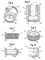
- shows a perspective exploded view of the polyaxial bone anchoring device with a spinal rod with a bone anchoring element with large pivot angle according to an embodiment of the invention.
- Fig. 2:
- shows a perspective view of the bone anchoring device of
Fig. 1 in an assembled state. - Fig. 3:
- shows a cross-sectional view of the bone anchoring device of
Figs. 1 and 2 in the assembled state without rod and fixation screw, the section taken along the rod axis. - Fig. 4:
- shows a cross-sectional view of the bone anchoring device of
Fig. 1 and 2 in the assembled state with inserted rod and fixation screw, the section taken along the rod axis. - Fig. 5:
- shows a perspective view from the bottom of the receiving part of the bone anchoring device according to
Figs. 1 to 4 . - Fig. 6:
- shows a cross-sectional view of the receiving part of
Fig. 5 , the section taken perpendicular to the rod axis. - Fig. 7:
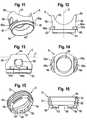
- shows a side view of the sleeve-like insert piece according to a first embodiment.
- Fig. 8:
- shows a perspective view from above of the sleeve-like insert piece.
- Fig. 9:
- shows a cross-sectional view of the sleeve-like insert piece, the section taken in a plane containing the central axis.
- Fig. 10:
- shows an enlarged portion of the sleeve-like insert piece according to
Fig. 9 . - Fig. 11:
- shows a perspective view of the pressure member of the polyaxial bone anchoring device.
- Fig. 12:
- shows a side view of the pressure member of
Fig. 11 along the rod axis. - Fig. 13:
- shows a side view of the pressure member of
Fig. 11 perpendicular to the rod axis. - Fig. 14:
- shows a top view of the pressure element of
Fig. 11 . - Fig. 15:
- shows a perspective view from the bottom of another embodiment of the sleeve-like insert piece.
- Fig. 16:
- shows a cross-sectional view of the sleeve-like insert piece of
Fig. 15 , the section taken in a plane containing the rod axis. - Figs. 17 to 28:
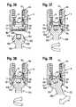
- show steps of assembling the polyaxial bone anchoring device.
- Figs. 29 to 32:
- show steps of adjusting an angle of the screw element with respect to the receiving part of the polyaxial bone anchoring device.
- Fig. 33:
- shows a perspective exploded view of the polyaxial bone anchoring device with a spinal rod with a bone anchoring element with a reduced pivot angle according to an embodiment of the invention.
- Fig. 34:
- shows a perspective view of the bone anchoring device of
Fig. 33 in an assembled state. - Fig. 35:
- shows a cross-sectional view of the bone anchoring device of
Fig. 34 , the section taken perpendicular to the rod axis. - Figs. 36 to 39:
- show steps of mounting the bone anchoring element of
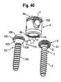
Fig. 33 to the receiving part and of pivoting the bone anchoring element. - Fig. 40:
- schematically shows the interchangeability of the bone anchoring elements with large pivot angle and with reduced pivot angle and the receiving part with inserted rod in a perspective view.
- Figs. 41 and 42:
- show sectional views, the section taken perpendicular to the rod axis, of the maximum pivot angle achieved with the bone anchoring device with the bone anchoring element having reduced pivot angle.
- Figs. 43 and 44:
- show cross-sectional views, the section taken perpendicular to the rod axis of the bone anchoring device with the bone anchoring element with large pivot angle.
- A polyaxial bone anchoring device with a large pivot angle of the bone anchoring element that is part of the of the polyaxial bone anchoring system will be described with reference to
Figs. 1 to 32 . - As shown in
Figs. 1 to 4 , a polyaxial bone anchoring device according to a first embodiment includes abone anchoring element 1 in the form of a bone screw having a threadedshank 2 and ahead 3. Thehead 3 typically has a spherically-shapedouter surface portion 3a and arecess 3b at its free end for engagement with a driver. Thehead 3 is held in a receivingpart 4 that couples thebone anchoring element 1 to astabilization rod 100. In the receivingpart 4, a sleeve-like insert piece 5 providing a seat for thehead 3 and apressure member 6 for exerting pressure onto thehead 3 of the bone anchoring element are arranged. Furthermore, a fixation element in the form of a fixation screw 7 is provided for securing and fixing therod 100 in the receivingpart 4. - The receiving
part 4 has atop end 4a and abottom end 4b, a central axis defining the central axis C of the polyaxial bone anchoring device and acoaxial bore 8 extending from thetop end 4a in the direction of thebottom end 4b. Adjacent to thetop end 4a, a substantiallyU-shaped recess 9 is provided that forms a channel for receiving therod 100. By means of the recess, two free legs are formed, which are provided with aninternal thread 10 that cooperates with the fixation screw 7. - The
coaxial bore 8 opens into anaccommodation space 11 provided in the lower part of the receivingpart 4. Theaccommodation space 11 has alower opening 12 at thebottom end 4b of the receivingpart 4 and is shaped as the portion of a hollow sphere including a largest inner diameter D. By theaccommodation space 11, a seat for the sleeve-like insert piece 5 is provided such that the seat and the sleeve-like insert piece form a ball and socket joint. It should be noted that the seat can also be tapered or can have another shape that can be used to realize a ball and socket joint. The inner diameter of thelower opening 12 is slightly smaller than the largest inner diameter D of theaccommodation space 11. - Adjacent the
opening 12, the receiving part comprises a threadedportion 13 with an internal thread. The height of the threadedportion 13 is such that it comprises only few thread turns, i.e. at least one thread turn and at maximum so many thread turns that the sleeve-like insert piece can freely pivot in the accommodation space once having passed the threadedportion 13 during insertion. In any case, the threadedportion 13 extends to a distance from the portion of theaccommodation space 11 having the largest inner diameter D. - It shall be further noted, that the inner diameter of the
coaxial bore 8 does not need to be constant between thetop end 4a and theaccommodation space 11. It may have different portion with different diameters. - The sleeve-
like insert piece 5 will be explained with reference toFigs. 3, 4 and7 to 10 . The sleeve-like insert piece 5 comprises anupper edge 5a, and alower edge 5b. Between theupper edge 5a and thelower edge 5b a threadedouter surface portion 51 is provided. The thread corresponds to the thread of the threadedportion 13 of the receiving part. Furthermore, the threadedouter surface portion 51 is spherically-shaped. The dimension of the threadedouter surface portion 51 is such that the sleeve-like insert piece 5 is insertable through theopening 12 by screwing and once it has passed the threadedportion 13, the sleeve-like insert piece 5 can pivot and rotate in the receiving part, when it is in the seat provided by theaccommodation space 11. The outer surface of theinsert piece 5 can also be only partially threaded with thethread portion 51 including the portion with the largest diameter. - The sleeve-
like insert piece 5 is hollow and comprises acentral portion 52, that is spherically-shaped with a radius corresponding to the radius of the spherically-shapedouter surface portion 3 a of thehead 3 of theanchoring element 1. The lower end of thiscentral portion 52 forms ashoulder 53. The inner diameter of theshoulder 53 is smaller than the largest outer diameter of thespherical head 3 such that thehead 3 can rotate and pivot in the centralspherical portion 52 of the sleeve-like insert piece 5 similar to a ball and socket joint. Between theshoulder 53 and thelower edge 5b, a taperedportion 54 can be provided that tapers outward to allow angulation of thebone anchoring element 1 until theshank 2 comes into contact with thelower edge 5b. Between the sphericalcentral portion 52 and theupper edge 5a, a taperedportion 55 is provided that tapers outwards. The inner diameter of the tapered portion and of the transition between the taperedportion 55 and the sphericalcentral portion 52 is greater than the largest outer diameter of thehead 3, so that thehead 3 can be inserted from theupper edge 5a. - The center points of the spherical
central portion 52 and of the outerspherical portion 51 may be offset in such a way that the center point of the centralspherical portion 52 is shifted in the direction towards thelower edge 5b. By means of this, the range of angulation for thebone anchoring element 1 can be further increased. The height of the sleeve-like insert piece 5 in an axial direction along the central axis C is less than the height of thehead 3 in axial direction, such that when thehead 3 is inserted into the sleeve-like insert piece 5, still a portion of the sphericalouter surface 3a of thehead 3 projects from theupper edge 5a of the sleeve-like insert piece 5 as shown inFigs. 3 and 4 . The inner diameter of the centralspherical portion 51 is dimensioned such that thehead 3 can hold the sleeve-like insert piece 5 by a slight tension caused by a friction fit. By means of this, the torque necessary for screwing-in of the screw element with the sleeve-like insert piece 5, can be transferred from the screw to the sleeve-like insert piece 5. - The sleeve-
like insert piece 5 is rigid, i.e. does not have any flexible portions such as, for example, slits that would render it flexible. - The
pressure member 6 is shown in particular inFigs. 3, 4 and11 to 14 . Thepressure member 6 is substantially cylindrical with an outer diameter that allows it to move within thecoaxial bore 8 and theaccommodation space 11. It has anupper end 6a and alower edge 6b. Adjacent itslower edge 6b, aspherical recess 61 with a spherical shape that matches the spherical shape of the outerspherical surface portion 3 a of thehead 3 is provided. - At the
upper end 6a, thepressure member 6 comprises acylindrical recess 63 for receiving therod 100 therein. Furthermore, thepressure member 6 has acoaxial bore 64 for allowing access to thescrew head 3 with a tool. Thecoaxial bore 64 is also configured to allow a portion of thehead 3 to extend therethrough, when the bone anchoring element is in a pivoted condition, as shown, for example, inFig. 3 . The height of thepressure member 6 in an axial direction along the central axis C is such that when the fixation screw 7 is tightened, it presses onto therod 100 which presses onto thepressure member 6 which in turn acts onto thehead 3 of the bone anchoring element. - At the outer surface of the
pressure member 6, two outwardly extendingprojections 65 that extend over a length in circumferential direction, are provided. Eachprojection 65 has anupper surface 65a facing theupper end 6a with a spherical shape matching the hollow spherical shape of theaccommodation space 11. Theprojections 65 are offset by 180° and located at a position perpendicular to the rod axis L as shown, for example, inFig. 13 . Theprojections 65a are located at a distance from thelower edge 6b and at a distance from the bottom of thecylindrical recess 63 towards thelower edge 6b seen in a direction of the central axis C. Above theprojections 65, tworecesses 66 are provided offset from each other by 180°. The recesses have aportion 66a extending into the sphericalupper surface 65a of theprojections 65. Therecesses 66 serve as a space for taking-up material of the inner wall of the receiving part generated by crimping as explained below. - A further embodiment of the sleeve-like insert piece 5' is shown in
Figs. 15 and 16 . The sleeve-like insert piece according toFigs. 15 and 16 differs from the sleeve-like insert piece 5 described before by the additional provision of a drive feature for engagement with a tool to screw-in the sleeve-like insert piece into the receiving part. All other portions are the same as in the first embodiment and are indicated by the same reference numerals. The description thereof will not be repeated. The sleeve-like insert piece 5' has at itslower edge 5b slits 56 that serve as an engagement portion for a tool. Theslits 56 can have any shape that allows engagement with a tool. A plurality ofslits 56 may be provided in a circumferential direction. If the sleeve-like insert piece 5' is used, thehead 3 needs not to be clamped in the sleeve-like insert piece 5'. - The bone anchoring device as a whole or in parts is made of a bio-compatible material, such as a bio-compatible metal, for example titanium, stainless steel, a bio-compatible alloy, such as nickel-titanium alloys, for example, Nitinol, or of bio-compatible plastic materials, such as, for example, polyetheretherketone (PEEK).
- Steps of assembling the bone anchoring device will be explained with reference to
Figs. 17 to 28 .Fig. 17 shows a side view of a first step of assembling. Thepressure member 6 is introduced into the receivingpart 4 through the upper orlower opening 12 until its cylindrical recess as shown inFig. 18 , projects slightly above the U-shaped recess of the receivingpart 4 and is aligned therewith. As shown in the sectional view according toFig. 21 , the pressure element is mounted to the receiving part by crimping, wherein with a crimping tool the inner wall of the receivingpart 4 is slightly deformed to formdeformed portions 41 protruding into therecesses 66. As therecesses 66 are in axial direction larger than thedeformed portions 41 at the inner wall, thepressure member 6 can slightly move within the receiving part in an axial direction. The receivingpart 4 and thepressure member 6 may be pre-assembled and delivered in such pre-assembled state. - The sleeve-
like insert part 5 is mounted to thebone anchoring element 1 as shown in a side view inFigs. 19 and 20 . The bone anchoring element is introduced from theupper edge 5a into the sleeve-like insert piece 5 until thespherical head 3 rests in the spherically-shapedcentral portion 52 and is slightly clamped therein. A large variety of bone anchoring elements each with or without mounted sleeve-like insert piece, may be provided. - As can be seen in
Figs. 21 to 24 , the bone anchoring element with mounted sleeve-like insert piece 5 is introduced from thebottom end 4b into the receivingpart 4.Fig. 21 shows a cross-sectional view of the polyaxial bone anchoring device with the section taken perpendicular to the rod axis.Fig. 22 shows a side view of the polyaxial bone anchoring device before assembling the bone anchoring element with the receiving part.Fig. 23 shows a cross-sectional view of the bone anchoring device andFig. 24 a side view thereof, wherein the bone anchoring element is introduced into the receivingpart 4 through thelower opening 12. The thread of theouter surface portion 51 of the sleeve-like insert piece 5 engages the threadedportion 13 of the receivingpart 4. Because the sleeve-like insert part 5 is slightly clamped onto thehead 3 of the bone anchoring element, the torque applied to the shank is transferred to the insert piece to engage the threadedportion 13. When the sleeve-like insert piece 5' is used, a tool may be used to screw-in the screw with the sleeve-like insert piece 5'. Figs. 25 and 26 show a cross-sectional view and a corresponding side view of the polyaxial bone anchoring device, wherein the bone anchoring element and the sleeve-like insert piece have been completely inserted. In this position, thepressure member 6 is at its uppermost position, in which the upperspherical portions 65a of theprojections 65 abut against the inner wall of theaccommodation space 11. The head of the screw and the sleeve-like insert piece are pivotable in the receiving part.- The assembly steps shown in
Figs. 19 to 26 can be performed by any person at any place. Therefore, a suitable polyaxial bone anchoring device can be selected from a great variety of bone anchoring elements assembled with receiving parts on demand. - In a final step shown in
Figs. 27 and 28 , whereinFig. 27 shows a cross-sectional view, andFig. 28 a corresponding side view of the polyaxial bone anchoring device, thepressure member 6 is further fixed by crimping. Through further crimping, thepressure member 6 is moved downward, until it slightly presses onto thescrew head 3 with itsspherical recess 61. By this additional crimping step,deformed portions 42 are generated that hold the pressure member in a predetermined preliminary position. By adjusting the force of the crimping operation, a defined friction fit is achieved between the screw head and the pressure member. The bone anchoring element can then be pivoted only by overcoming the frictional force between thepressure member 6 and thescrew head 3. - The assembly of the bone anchoring element and the receiving part with the second embodiment of the sleeve-like insert piece 5' is carried out in the same manner as the first embodiment except that a tool is used for engaging the
slits 56 and rotating the sleeve-like insert piece 5'. - The steps of use of the bone anchoring device are shown by the cross-sectional views of
Figs. 29 to 32 . The fixation screw and the rod are omitted. First, the anchoring element is inserted in the bone part or in a vertebra. Usually, several bone anchoring devices are needed to fix a stabilization rod to the bone parts or the vertebrae to be stabilized. After the bone anchoring elements are inserted, one example of which is shown inFigs. 29 to 32 , the receivingpart 4 is adjusted by pivoting and/or rotating it in order to be able to insert the stabilization rod into theU-shaped recess 9. In the condition shown inFigs. 29 to 32 , both, the sleeve-like insert piece 5 and thehead 3 of thebone anchoring element 1 are independently and freely pivotable. The sleeve-like insert piece 5 is rotatable and pivotable in the receivingpart 4 and the receivingpart 4 as well as the sleeve-like insert piece are rotatable and pivotable with respect to thehead 3 of the bone anchoring element. The sleeve-like insert piece 5 provides for an enlarged range of angulation compared to a case in that thehead 3 is directly received in the receivingpart 5, because the distance between theshank 2 and thelower end 4b of the receiving part is greater. Because the sleeve-like insert piece 5 is rotatable and pivotable within the receivingpart 4, the enlarged range of angulation can be achieved at any position of the receiving part with respect to the bone anchoring element within 360° around the central axis C of the receiving part. As shown inFig. 30 , pivoting the receivingpart 4 to the opposite direction also pivots the sleeve-like insert piece 5. - As shown in
Fig. 31a and in the enlarged representation ofFig. 31b , further pivoting the receiving part essentially maintains the position of the sleeve-like insert piece 5. As soon as theshank 2 of the bone anchoring element comes into contact with thelower edge 5b of the sleeve-like insert piece as shown inFig. 31a and 31b , the sleeve-like insert piece 5 is also pivoted. Theshank 2 pushes theinsert piece 5 until theshank 2 abuts against the edge of thelower opening 12 of the receiving part as shown inFig. 32 . Hence, inFig. 32 , the receiving part is pivoted at a maximum pivot angle with respect to thebone anchoring element 1. The maximum pivot angle to be achieved depends on the dimensions of the sleeve-like insert piece 5 and the receiving part and the bone anchoring element but is typically equal to or greater than 45° measured from the straight, i.e. zero angle position. - While in
Figs. 29 to 32 an example is shown in which pivoting is carried out in a plane that contains the rod axis, it should be noted, that the same steps can be carried out at any other direction within 360° around the central axis C of the receivingpart 4. - The sleeve-like insert piece together with the bone anchoring element can not escape from the
lower opening 12 because of the obstacle provided by the threadedportion 13. The friction fit between thepressure member 6 and thehead 3 of the screw has the effect that the receivingpart 4 can be maintained provisionally at any position with respect to the bone anchoring element. Finally, the rod is inserted and the inner screw 7 is tightened to press thepressure element 6 onto the head to lock the head and the sleeve-like insert piece simultaneously. - A polyaxial bone anchoring device with a reduced pivot angle of the bone anchoring element that is part of the polyaxial bone anchoring system will be described with reference to
Figs. 33 to 39 . - The bone anchoring device shown in
Figs. 33 to 35 differs from the bone anchoring device shown inFigs. 1 to 32 in the design of the bone anchoring element. The receiving part, thepressure member 6 and the inner screw 7 are the same as in the previous figures, so that the description thereof will not be repeated. - The
bone anchoring element 101 has a threadedshank 102 and ahead 103. Thehead 103 has afirst portion 104 adjacent the threadedshank 102 that is shaped substantially shaped as a hemisphere with increasing diameter away from the threadedshank 102. At the end of the hemisphere facing away from the threadedshank 102, a threadedouter surface portion 105 is provided. The outer diameter matches with the inner diameter of the threadedportion 13 at the lower portion of the receivingpart 4. In other words, the outer diameter of the threadedouter surface portion 105 of thehead 103 corresponds substantially to the outer diameter of the sleeve-like insert piece 5, 5' of thebone anchoring element 1 of the previous embodiment. Thehead 103 further comprises asecond portion 106 which is threadless and spherically-shaped with increasing diameter in the direction towards theshank 102. The diameter of thesecond portion 106 is smaller than that of thefirst portion 104 and substantially corresponds to the inner diameter of thespherical recess 61 of thepressure member 6. Thehead 103 further has at its free end opposite to the shank 102 arecess 108 for engagement with a tool. Between thefirst portion 104 and the second portion 106 acircumferential groove 107 is provided that serves for engagement by the lower edge of thepressure member 6. - Also the
second anchoring element 101 can have different types of shanks, with respect to the length, the diameter and the design of the shank. - The
bone anchoring element 101 is mounted to the receivingpart 4 from thebottom end 4b. As shown inFigs. 36 and 37 , first, thebone anchoring element 101 is moved with itshead 103 towards thelower opening 12 until the threadedouter surface portion 105 engages the threadedportion 13 at the lower end of the receiving part (Fig. 37 ). Then, thebone anchoring element 101 is further screwed to the receiving part in a zero angle position, as shown inFig. 38 . When the threadedportion 105 of thehead 103 has passed the threadedportion 13 the receivingpart 4, the anchoring 101 can freely pivot in the accommodation space as shown inFig. 39 . It can not fall out, due to the threadedportion 13 acting as a stop. Thepressure member 6 can be positioned such that it exerts a preload onto thehead 103 in order to allow pivoting of thebone anchoring element 101 only by application of a force that overcomes the friction force. When thebone anchoring element 101 is received in theaccommodation space 11 thepressure member 6 engages thesecond portion 106 of thehead 103. - As shown in
Fig. 40 , thebone anchoring element 1 with the sleeve-like insert piece 5 and thebone anchoring element 101 can be selectively connected to the receivingpart 4 by insertion through thelower opening 12. - Because the outer dimensions of the
first portion 104 of thehead 103 of thebone anchoring element 101 fits to the inner dimensions of the threadedportion 13 of theaccommodation space 11 of the receiving part in the same manner as the outer dimensions of the sleeve-like insert piece 5, 5' of the firstbone anchoring element 1 fit thereto, thebone anchoring elements bone anchoring element 1 with sleeve-like insert piece 5, 5' or whether it shall be a bone anchoring device with a reduced pivot angle having thebone anchoring element 101. Fig. 41 and Fig. 42 show the bone anchoring device with thebone anchoring element 101 with the reduced pivot angle wherein the bone anchoring element is pivoted to its maximum angle towards one side (Fig. 41 ) and towards the other side (Fig. 42 ). The maximum pivot angle is defined by the condition in which the threadedouter surface portion 105 begins to disengage the threadedportion 13. Thepressure member 6 presses onto thehead 103 and its lower edge engages thegroove 107.Fig. 43 and Fig. 44 show the bone anchoring device with thebone anchoring element 1 in a condition in which thebone anchoring element 101 is pivoted to its maximum pivot angle to one side (Fig. 43 ) and to the other side (Fig. 44 ). The maximum pivot angle is defined when the threadedshank 2 abuts against thebottom end 4b. Due to the sleeve-like insert piece the maximum pivot angle is substantially larger than for the bone anchoring device with thebone anchoring element 101 as shown inFigs. 41 and 42 .- Because all parts of the bone anchoring system comprising the receiving part with the
pressure element 6 on the one hand and thebone anchoring element 1 with the sleeve-like insert piece 5, 5' and thebone anchoring element 101 on the other hand are easy to assemble, a modular system that opens a broad range of clinical applications is provided. - Further modifications of the embodiments described are conceivable. For example, for the bone anchoring element, all kinds of anchoring elements can be used and combined with the receiving part. These anchoring elements are e.g. screws of different length, with different diameters, canulated screws, screws with different thread forms, nails, hooks, etc. The head and the shank may also be separate parts that are connectable to each other.
- Modifications of the receiving part include instead of the U-shaped recess, which is perpendicular to the central axis, a recess for the rod, which is inclined or open to the side or which is in the form of a closed channel. Other kinds of locking devices including outer nuts, outer caps, bayonet locking devices or others are possible. The locking device can also be a two part locking device having one locking element that locks the head and another locking element that locks the rod. In all embodiments, the inner surface portion of the pressure member that contacts the
head 3, needs not necessarily to be spherically-shaped. It can have another shape that is suitable to exert pressure onto the head. - The polyaxial bone anchoring system can also be realized through any receiving part, a first bone anchoring element that is pivotable in the receiving part to a first maximum pivot angle and a second bone anchoring element that is pivotable in the receiving part to a second maximum pivot angle wherein the first maximum pivot angle is larger than the second maximum pivot angle and wherein the first and the scone bone anchoring elements are configured to be interchangeable.
Claims (14)
- A polyaxial bone anchoring system including
a first anchoring element (1) having a first shank (2) for anchoring in the bone or a vertebra and a first head (3), the head having a spherically-shaped outer surface portion (3a) and wherein the first bone anchoring element (1) comprises a sleeve-like insert piece (5, 5') encompassing a portion of the first head (3) and being configured to pivot in the accommodation space (11) of the receiving part (4);
a second anchoring element (101) having a second shank (102) for anchoring in the bone or a vertebra and a second head (103),
a receiving part (4), the receiving part having a top end (4a) and a bottom end (4b), a central axis (C) extending through the top end and the bottom end, a transverse channel (9) for receiving a rod (100) and an accommodation space (11) for accommodating the head (3), the accommodation space (11) having a lower opening (12) at the bottom end (4b),
a pressure member (6), the pressure member being arranged at least partially in the accommodation space (11) and wherein the pressure member has a lower surface portion (61) that contacts the first head (3) or the second head (103) to exert pressure onto the first head (3) or the second head (103);
wherein the first anchoring element (1) and the second bone anchoring element (101), respectively, are pivotable with respect to the receiving part (4) and can be locked at an angle by exerting pressure with the pressure member (6) onto the first head (3) or the second head (103) to lock the first head (3) or the second head (103) in the receiving part (4);
and wherein the first head (3) with the sleeve like insert piece (5, 5') and the second head (103) each are configured to be introduced into the accommodation space through the lower opening and wherein the first bone anchoring element and the second bone anchoring element are configured to be interchangeable;
and wherein the receiving part (4) has a first engagement portion (13) near the bottom end (4b)the sleeve-like insertpiece (5) has a second engagement portion (51) for engaging the first engagement portion (13), the second head (103) has a third engagement portion (105) for engaging the first engagement portion (13),
and wherein the first engagement portion (13), the second engagement portion (51) and the third engagement portion (105) are threaded portions. - The polyaxial bone anchoring system of claim 1, wherein the accommodation space (11) has a largest diameter (D) and wherein the first engagement portion (13) extends from the lower opening (12) to a distance from the largest diameter (D) of the accommodation space.
- The polyaxial bone anchoring system of claims 1 or 2, wherein the sleeve-like insert piece (5, 5') is insertable into the accommodation space (11) through the lower opening (12) by advancing it into the accommodation space (11) such that the first engagement portion (13) engages the second engagement portion (51) and after disengagement of the first engagement portion (13) and the second engagement portion (51) the sleeve-like insert piece is freely pivotable in the accommodation space (11).
- The polyaxial bone anchoring device of one of claims 1 to 3, wherein the second engagement portion (51) extends over about the full outer surface of the sleeve-like insert piece (5).
- The polyaxial bone anchoring device of one of claims 1 to 4, wherein the sleeve-like insert piece (5, 5') is held on the first head (3) by friction.
- The polyaxial bone anchoring device of one of claims 1 to 5, wherein the sleeve-like insert piece (5') has an upper edge (5a) and a lower edge (5b) and wherein an engagement portion for a tool (56) is provided at the lower edge (5b).
- The polyaxial bone anchoring device of one of claims 1 to 6, wherein the sleeve-like insert piece (5, 5') and the anchoring element (1) are independently pivotable when the shank (2) of the anchoring element (1) and the lower edge (5b) of the sleeve-like insert piece (5, 5') are out of contact.
- The polyaxial bone anchoring device of one of claims 1 to 7, wherein, when the shank (2) of the anchoring element (1) is pivoted and engages the lower edge (5b) of the sleeve-like insert piece (5, 5'), further pivoting of the anchoring element (1) causes the sleeve-like insert piece (5) to pivot together with the anchoring element (1).
- The polyaxial bone anchoring device of one of claims 1 to 8, wherein the sleeve-like insert piece (5, 5') has an inner spherical surface portion (52) that forms a seat for the first head (3).
- The polyaxial bone anchoring system of one of claims 1 to 9, wherein the second head (103) has a first portion (104) that comprises the third engagement portion (105) and a second portion (106) onto which the pressure member (6) acts.
- The polyaxial bone anchoring system of claim 10, wherein the first portion (104) is spherically shaped.
- The polyaxial bone anchoring system of one of claims 1 to 11, wherein the first engagement portion (13) and the second engagement portion (51) provides a stop a stop for the sleeve-like insert piece (5, 5') and wherein the first engagement portion (13) and the third engagement portion (105) provide a stop for the second head (103) with regard to moving out of the opening (12), respectively.
- The polyaxial bone anchoring system of one of claims 1 to 12, wherein the accommodation space (11) has a hollow spherically-shaped portion forming a seat for the sleeve-like insert piece (5, 5') or for the second head (103), respectively.
- The polyaxial bone anchoring system of one of claims 1 to 13 wherein the first anchoring element (1) is pivotable to a first maximum pivot angle and the second bone anchoring element (101) is pivotable to a second maximum pivot angle that is smaller than the first maximum pivot angle.
Priority Applications (7)
| Application Number | Priority Date | Filing Date | Title |
|---|---|---|---|
| ES11178037.5TES2504068T3 (en) | 2011-08-18 | 2011-08-18 | Polyaxial bone anchoring system |
| EP11178037.5AEP2559391B1 (en) | 2011-08-18 | 2011-08-18 | Polyaxial bone anchoring system |
| CN201210290286.2ACN102949233B (en) | 2011-08-18 | 2012-08-15 | Polyaxial bone anchor system |
| TW101129446ATW201309257A (en) | 2011-08-18 | 2012-08-15 | Polyaxial bone anchoring system |
| US13/586,691US9277938B2 (en) | 2011-08-18 | 2012-08-15 | Polyaxial bone anchoring system |
| JP2012180034AJP6076648B2 (en) | 2011-08-18 | 2012-08-15 | Multiaxial bone anchoring system |
| KR1020120089698AKR20130020609A (en) | 2011-08-18 | 2012-08-16 | Polyaxial bone anchoring system |
Applications Claiming Priority (1)
| Application Number | Priority Date | Filing Date | Title |
|---|---|---|---|
| EP11178037.5AEP2559391B1 (en) | 2011-08-18 | 2011-08-18 | Polyaxial bone anchoring system |
Publications (2)
| Publication Number | Publication Date |
|---|---|
| EP2559391A1 EP2559391A1 (en) | 2013-02-20 |
| EP2559391B1true EP2559391B1 (en) | 2014-06-18 |
Family
ID=44532671
Family Applications (1)
| Application Number | Title | Priority Date | Filing Date |
|---|---|---|---|
| EP11178037.5AActiveEP2559391B1 (en) | 2011-08-18 | 2011-08-18 | Polyaxial bone anchoring system |
Country Status (7)
| Country | Link |
|---|---|
| US (1) | US9277938B2 (en) |
| EP (1) | EP2559391B1 (en) |
| JP (1) | JP6076648B2 (en) |
| KR (1) | KR20130020609A (en) |
| CN (1) | CN102949233B (en) |
| ES (1) | ES2504068T3 (en) |
| TW (1) | TW201309257A (en) |
Families Citing this family (30)
| Publication number | Priority date | Publication date | Assignee | Title |
|---|---|---|---|---|
| US9980753B2 (en)* | 2009-06-15 | 2018-05-29 | Roger P Jackson | pivotal anchor with snap-in-place insert having rotation blocking extensions |
| AU2010260521C1 (en)* | 2008-08-01 | 2013-08-01 | Roger P. Jackson | Longitudinal connecting member with sleeved tensioned cords |
| CN103826560A (en) | 2009-06-15 | 2014-05-28 | 罗杰.P.杰克逊 | Polyaxial Bone Anchor with Socket Stem and Winged Inserts with Friction Fit Compression Collars |
| US9345519B1 (en)* | 2010-07-02 | 2016-05-24 | Presidio Surgical, Inc. | Pedicle screw |
| AU2011324058A1 (en)* | 2010-11-02 | 2013-06-20 | Roger P. Jackson | Polyaxial bone anchor with pop-on shank and pivotable retainer |
| JP5865479B2 (en)* | 2011-03-24 | 2016-02-17 | ロジャー・ピー・ジャクソン | Multiaxial bone anchor with compound joint and pop-mounted shank |
| US9993269B2 (en)* | 2011-07-15 | 2018-06-12 | Globus Medical, Inc. | Orthopedic fixation devices and methods of installation thereof |
| US20130211467A1 (en)* | 2012-02-10 | 2013-08-15 | Warsaw Orthopedic, Inc. | Connector and fastener system |
| US9259247B2 (en) | 2013-03-14 | 2016-02-16 | Medos International Sarl | Locking compression members for use with bone anchor assemblies and methods |
| WO2014169189A1 (en)* | 2013-04-12 | 2014-10-16 | Alphatec Spine, Inc. | Uniplanar screw assembly and methods of use |
| US10064657B2 (en)* | 2014-04-02 | 2018-09-04 | FloSpine, LLC | Polyaxial bone anchor incorporating a threaded bone screw and compression saddle |
| US10543021B2 (en) | 2014-10-21 | 2020-01-28 | Roger P. Jackson | Pivotal bone anchor assembly having an open ring positioner for a retainer |
| US10363073B2 (en) | 2016-07-13 | 2019-07-30 | Medos International Sàrl | Bone anchor assemblies and related instrumentation |
| US10568667B2 (en) | 2016-07-13 | 2020-02-25 | Medos International Sàrl | Bone anchor assemblies and related instrumentation |
| US10463402B2 (en) | 2016-07-13 | 2019-11-05 | Medos International Sàrl | Bone anchor assemblies and related instrumentation |
| US10874438B2 (en) | 2016-07-13 | 2020-12-29 | Medos International Sarl | Bone anchor assemblies and related instrumentation |
| EP3570765B1 (en)* | 2017-01-18 | 2023-07-05 | K2M, Inc. | Modular spinal fixation device |
| US11298156B2 (en) | 2017-03-30 | 2022-04-12 | K2M, Inc. | Modular screw |
| WO2018183486A1 (en) | 2017-03-30 | 2018-10-04 | K2M, Inc. | Modular offset screw |
| AU2018243875B2 (en) | 2017-03-30 | 2022-05-26 | K2M, Inc. | Bone anchor apparatus and method of use thereof |
| US10610265B1 (en) | 2017-07-31 | 2020-04-07 | K2M, Inc. | Polyaxial bone screw with increased angulation |
| EP3695796B1 (en)* | 2019-02-13 | 2022-08-03 | Biedermann Technologies GmbH & Co. KG | Anchoring assembly for anchoring a rod to a bone or a vertebra |
| CN113545834B (en)* | 2020-04-26 | 2024-06-21 | 上海三友医疗器械股份有限公司 | Pedicle screw and screw connection assembly |
| WO2021263088A1 (en) | 2020-06-26 | 2021-12-30 | K2M, Inc. | Modular head assembly |
| WO2022108875A1 (en) | 2020-11-19 | 2022-05-27 | K2M, Inc. | Modular head assembly for spinal fixation |
| US12364515B2 (en) | 2021-03-05 | 2025-07-22 | Medos International Sàrl | Multi-feature polyaxial screw |
| WO2022184797A1 (en) | 2021-03-05 | 2022-09-09 | Medos International Sarl | Selectively locking polyaxial screw |
| US12414801B2 (en)* | 2022-11-03 | 2025-09-16 | Roger P. Jackson | Spinal fixation system with modular receiver sub-assemblies for connecting with bi-spherical universal shank heads |
| EP4437983A1 (en) | 2023-03-30 | 2024-10-02 | Biedermann Technologies GmbH & Co. KG | Coupling device for coupling a rod to a bone anchor and system of such a coupling device and at least two bone anchors |
| EP4570198A1 (en) | 2023-12-15 | 2025-06-18 | Biedermann Technologies GmbH & Co. KG | Coupling device for coupling a rod to a bone anchor and system of such a coupling device and at least two bone anchors |
Family Cites Families (40)
| Publication number | Priority date | Publication date | Assignee | Title |
|---|---|---|---|---|
| DE10055888C1 (en) | 2000-11-10 | 2002-04-25 | Biedermann Motech Gmbh | Bone screw, has connector rod receiving part with unsymmetrically arranged end bores |
| US8292926B2 (en) | 2005-09-30 | 2012-10-23 | Jackson Roger P | Dynamic stabilization connecting member with elastic core and outer sleeve |
| AU2003287273C1 (en) | 2002-10-30 | 2010-01-07 | Zimmer Spine, Inc. | Spinal stabilization system insertion and methods |
| FR2847152B1 (en)* | 2002-11-19 | 2005-02-18 | Eurosurgical | VERTEBRAL ANCHORING DEVICE AND ITS LOCKING DEVICE ON A POLY AXIAL SCREW |
| US8540753B2 (en)* | 2003-04-09 | 2013-09-24 | Roger P. Jackson | Polyaxial bone screw with uploaded threaded shank and method of assembly and use |
| US6716214B1 (en) | 2003-06-18 | 2004-04-06 | Roger P. Jackson | Polyaxial bone screw with spline capture connection |
| US20070016200A1 (en)* | 2003-04-09 | 2007-01-18 | Jackson Roger P | Dynamic stabilization medical implant assemblies and methods |
| US8926670B2 (en)* | 2003-06-18 | 2015-01-06 | Roger P. Jackson | Polyaxial bone screw assembly |
| US8377102B2 (en) | 2003-06-18 | 2013-02-19 | Roger P. Jackson | Polyaxial bone anchor with spline capture connection and lower pressure insert |
| US7322981B2 (en) | 2003-08-28 | 2008-01-29 | Jackson Roger P | Polyaxial bone screw with split retainer ring |
| US20100211114A1 (en) | 2003-06-18 | 2010-08-19 | Jackson Roger P | Polyaxial bone anchor with shelf capture connection |
| US7776067B2 (en) | 2005-05-27 | 2010-08-17 | Jackson Roger P | Polyaxial bone screw with shank articulation pressure insert and method |
| US7967850B2 (en)* | 2003-06-18 | 2011-06-28 | Jackson Roger P | Polyaxial bone anchor with helical capture connection, insert and dual locking assembly |
| DE102004010380A1 (en) | 2004-03-03 | 2005-09-22 | Biedermann Motech Gmbh | Anchoring element and stabilizing device for the dynamic stabilization of vertebrae or bones with such an anchoring element |
| DE102004010382B4 (en) | 2004-03-03 | 2006-04-20 | Biedermann Motech Gmbh | Bone anchoring element for anchoring in a bone or in a vertebra and its use in a stabilizing device |
| US7604655B2 (en) | 2004-10-25 | 2009-10-20 | X-Spine Systems, Inc. | Bone fixation system and method for using the same |
| US8444681B2 (en)* | 2009-06-15 | 2013-05-21 | Roger P. Jackson | Polyaxial bone anchor with pop-on shank, friction fit retainer and winged insert |
| US8308782B2 (en) | 2004-11-23 | 2012-11-13 | Jackson Roger P | Bone anchors with longitudinal connecting member engaging inserts and closures for fixation and optional angulation |
| US7445627B2 (en) | 2005-01-31 | 2008-11-04 | Alpinespine, Llc | Polyaxial pedicle screw assembly |
| US10076361B2 (en) | 2005-02-22 | 2018-09-18 | Roger P. Jackson | Polyaxial bone screw with spherical capture, compression and alignment and retention structures |
| US7476239B2 (en) | 2005-05-10 | 2009-01-13 | Jackson Roger P | Polyaxial bone screw with compound articulation |
| US20090093844A1 (en) | 2005-09-30 | 2009-04-09 | Jackson Roger P | Elastic covered dynamic stabilization connector and assembly |
| US8100946B2 (en) | 2005-11-21 | 2012-01-24 | Synthes Usa, Llc | Polyaxial bone anchors with increased angulation |
| US8133262B2 (en) | 2006-04-28 | 2012-03-13 | Depuy Spine, Inc. | Large diameter bone anchor assembly |
| US7922748B2 (en)* | 2006-06-16 | 2011-04-12 | Zimmer Spine, Inc. | Removable polyaxial housing for a pedicle screw |
| US20080004625A1 (en)* | 2006-06-27 | 2008-01-03 | Runco Thomas J | Bone anchor assemblies |
| AU2008206396A1 (en) | 2007-01-12 | 2008-07-24 | Lanx, Inc. | Bone fastener assembly |
| WO2008118295A2 (en)* | 2007-03-26 | 2008-10-02 | Laszlo Garamszegi | Bottom-loading pedicle screw assembly |
| KR20100014881A (en) | 2007-04-09 | 2010-02-11 | 신세스 게엠바하 | Bone fixation element |
| PL2170192T3 (en) | 2007-07-20 | 2011-07-29 | Synthes Gmbh | Polyaxial bone fixation element |
| WO2009055400A1 (en)* | 2007-10-23 | 2009-04-30 | K2M, Inc. | Polyaxial screw assembly |
| KR100895243B1 (en)* | 2008-02-27 | 2009-04-30 | 최길운 | Buffered pedicle screws |
| US8696717B2 (en)* | 2008-11-05 | 2014-04-15 | K2M, Inc. | Multi-planar, taper lock screw with additional lock |
| EP2485654B1 (en) | 2009-10-05 | 2021-05-05 | Jackson P. Roger | Polyaxial bone anchor with non-pivotable retainer and pop-on shank, some with friction fit |
| US10111694B2 (en)* | 2010-10-05 | 2018-10-30 | Skeletal Design Partnership, Llc | Pedicle screw assembly and method of assembly |
| DE102010060555A1 (en) | 2010-11-15 | 2012-05-16 | Ulrich Gmbh & Co. Kg | pedicle screw |
| EP2457527B1 (en) | 2010-11-24 | 2014-04-16 | Biedermann Technologies GmbH & Co. KG | Polyaxial bone anchoring device with enlarged pivot angle |
| JP5865479B2 (en) | 2011-03-24 | 2016-02-17 | ロジャー・ピー・ジャクソン | Multiaxial bone anchor with compound joint and pop-mounted shank |
| ES2504067T3 (en)* | 2011-08-18 | 2014-10-08 | Biedermann Technologies Gmbh & Co. Kg | Polyaxial bone anchoring device with extended turning angle |
| KR101328579B1 (en)* | 2011-11-30 | 2013-11-12 | (주)엘앤케이바이오메드 | Screw for fixing vertebra |
- 2011
- 2011-08-18EPEP11178037.5Apatent/EP2559391B1/enactiveActive
- 2011-08-18ESES11178037.5Tpatent/ES2504068T3/enactiveActive
- 2012
- 2012-08-15TWTW101129446Apatent/TW201309257A/enunknown
- 2012-08-15JPJP2012180034Apatent/JP6076648B2/ennot_activeExpired - Fee Related
- 2012-08-15CNCN201210290286.2Apatent/CN102949233B/ennot_activeExpired - Fee Related
- 2012-08-15USUS13/586,691patent/US9277938B2/enactiveActive
- 2012-08-16KRKR1020120089698Apatent/KR20130020609A/ennot_activeWithdrawn
Also Published As
| Publication number | Publication date |
|---|---|
| US20130096621A1 (en) | 2013-04-18 |
| US9277938B2 (en) | 2016-03-08 |
| ES2504068T3 (en) | 2014-10-08 |
| KR20130020609A (en) | 2013-02-27 |
| EP2559391A1 (en) | 2013-02-20 |
| JP6076648B2 (en) | 2017-02-08 |
| CN102949233B (en) | 2016-08-24 |
| CN102949233A (en) | 2013-03-06 |
| JP2013039371A (en) | 2013-02-28 |
| TW201309257A (en) | 2013-03-01 |
Similar Documents
| Publication | Publication Date | Title |
|---|---|---|
| EP2559391B1 (en) | Polyaxial bone anchoring system | |
| EP2559390B1 (en) | Polyaxial bone anchoring device with enlarged pivot angle | |
| EP2462889B1 (en) | Bone anchoring device | |
| US7892259B2 (en) | Bone anchoring device | |
| US8361129B2 (en) | Large diameter bone anchor assembly | |
| EP2570090B1 (en) | Polyaxial bone anchoring device with enlarged pivot angle | |
| EP2335625B1 (en) | Bone anchoring device | |
| EP2837347B1 (en) | Bone anchoring device | |
| EP2468198B1 (en) | Bone anchoring device | |
| EP3047812B1 (en) | Polyaxial bone anchoring device | |
| EP2586392B1 (en) | High angulation polyaxial bone anchoring device | |
| EP2468199B1 (en) | Polyaxial bone anchoring device | |
| EP2604204B1 (en) | Monoplanar bone anchoring device with selectable pivot plane | |
| US20080015597A1 (en) | Large diameter bone anchor assembly | |
| US20080004625A1 (en) | Bone anchor assemblies | |
| US20080015596A1 (en) | Large diameter multiple piece bone anchor assembly | |
| US20080015576A1 (en) | Large diameter bone anchor assembly | |
| US20060235385A1 (en) | Low profile polyaxial screw | |
| US9005249B2 (en) | Spinal rod connector assembly | |
| US12318120B2 (en) | Bone anchoring device |
Legal Events
| Date | Code | Title | Description |
|---|---|---|---|
| PUAI | Public reference made under article 153(3) epc to a published international application that has entered the european phase | Free format text:ORIGINAL CODE: 0009012 | |
| AK | Designated contracting states | Kind code of ref document:A1 Designated state(s):AL AT BE BG CH CY CZ DE DK EE ES FI FR GB GR HR HU IE IS IT LI LT LU LV MC MK MT NL NO PL PT RO RS SE SI SK SM TR | |
| AX | Request for extension of the european patent | Extension state:BA ME | |
| 17P | Request for examination filed | Effective date:20130819 | |
| RBV | Designated contracting states (corrected) | Designated state(s):AL AT BE BG CH CY CZ DE DK EE ES FI FR GB GR HR HU IE IS IT LI LT LU LV MC MK MT NL NO PL PT RO RS SE SI SK SM TR | |
| GRAP | Despatch of communication of intention to grant a patent | Free format text:ORIGINAL CODE: EPIDOSNIGR1 | |
| RIC1 | Information provided on ipc code assigned before grant | Ipc:A61B 17/70 20060101AFI20131122BHEP | |
| INTG | Intention to grant announced | Effective date:20140102 | |
| GRAS | Grant fee paid | Free format text:ORIGINAL CODE: EPIDOSNIGR3 | |
| GRAA | (expected) grant | Free format text:ORIGINAL CODE: 0009210 | |
| AK | Designated contracting states | Kind code of ref document:B1 Designated state(s):AL AT BE BG CH CY CZ DE DK EE ES FI FR GB GR HR HU IE IS IT LI LT LU LV MC MK MT NL NO PL PT RO RS SE SI SK SM TR | |
| REG | Reference to a national code | Ref country code:GB Ref legal event code:FG4D | |
| RIN1 | Information on inventor provided before grant (corrected) | Inventor name:MEER, MARTIN Inventor name:BIEDERMANN, LUTZ Inventor name:MATTHIS, WILFRIED | |
| REG | Reference to a national code | Ref country code:CH Ref legal event code:NV Representative=s name:NOVAGRAAF INTERNATIONAL SA, CH Ref country code:CH Ref legal event code:EP | |
| REG | Reference to a national code | Ref country code:AT Ref legal event code:REF Ref document number:672888 Country of ref document:AT Kind code of ref document:T Effective date:20140715 | |
| REG | Reference to a national code | Ref country code:IE Ref legal event code:FG4D | |
| REG | Reference to a national code | Ref country code:DE Ref legal event code:R096 Ref document number:602011007724 Country of ref document:DE Effective date:20140731 | |
| REG | Reference to a national code | Ref country code:ES Ref legal event code:FG2A Ref document number:2504068 Country of ref document:ES Kind code of ref document:T3 Effective date:20141008 | |
| PG25 | Lapsed in a contracting state [announced via postgrant information from national office to epo] | Ref country code:FI Free format text:LAPSE BECAUSE OF FAILURE TO SUBMIT A TRANSLATION OF THE DESCRIPTION OR TO PAY THE FEE WITHIN THE PRESCRIBED TIME-LIMIT Effective date:20140618 Ref country code:NO Free format text:LAPSE BECAUSE OF FAILURE TO SUBMIT A TRANSLATION OF THE DESCRIPTION OR TO PAY THE FEE WITHIN THE PRESCRIBED TIME-LIMIT Effective date:20140918 Ref country code:LT Free format text:LAPSE BECAUSE OF FAILURE TO SUBMIT A TRANSLATION OF THE DESCRIPTION OR TO PAY THE FEE WITHIN THE PRESCRIBED TIME-LIMIT Effective date:20140618 Ref country code:GR Free format text:LAPSE BECAUSE OF FAILURE TO SUBMIT A TRANSLATION OF THE DESCRIPTION OR TO PAY THE FEE WITHIN THE PRESCRIBED TIME-LIMIT Effective date:20140919 Ref country code:CY Free format text:LAPSE BECAUSE OF FAILURE TO SUBMIT A TRANSLATION OF THE DESCRIPTION OR TO PAY THE FEE WITHIN THE PRESCRIBED TIME-LIMIT Effective date:20140618 | |
| REG | Reference to a national code | Ref country code:NL Ref legal event code:VDEP Effective date:20140618 | |
| REG | Reference to a national code | Ref country code:AT Ref legal event code:MK05 Ref document number:672888 Country of ref document:AT Kind code of ref document:T Effective date:20140618 | |
| REG | Reference to a national code | Ref country code:LT Ref legal event code:MG4D | |
| PG25 | Lapsed in a contracting state [announced via postgrant information from national office to epo] | Ref country code:LV Free format text:LAPSE BECAUSE OF FAILURE TO SUBMIT A TRANSLATION OF THE DESCRIPTION OR TO PAY THE FEE WITHIN THE PRESCRIBED TIME-LIMIT Effective date:20140618 Ref country code:HR Free format text:LAPSE BECAUSE OF FAILURE TO SUBMIT A TRANSLATION OF THE DESCRIPTION OR TO PAY THE FEE WITHIN THE PRESCRIBED TIME-LIMIT Effective date:20140618 Ref country code:RS Free format text:LAPSE BECAUSE OF FAILURE TO SUBMIT A TRANSLATION OF THE DESCRIPTION OR TO PAY THE FEE WITHIN THE PRESCRIBED TIME-LIMIT Effective date:20140618 Ref country code:SE Free format text:LAPSE BECAUSE OF FAILURE TO SUBMIT A TRANSLATION OF THE DESCRIPTION OR TO PAY THE FEE WITHIN THE PRESCRIBED TIME-LIMIT Effective date:20140618 | |
| PG25 | Lapsed in a contracting state [announced via postgrant information from national office to epo] | Ref country code:SK Free format text:LAPSE BECAUSE OF FAILURE TO SUBMIT A TRANSLATION OF THE DESCRIPTION OR TO PAY THE FEE WITHIN THE PRESCRIBED TIME-LIMIT Effective date:20140618 Ref country code:CZ Free format text:LAPSE BECAUSE OF FAILURE TO SUBMIT A TRANSLATION OF THE DESCRIPTION OR TO PAY THE FEE WITHIN THE PRESCRIBED TIME-LIMIT Effective date:20140618 Ref country code:RO Free format text:LAPSE BECAUSE OF FAILURE TO SUBMIT A TRANSLATION OF THE DESCRIPTION OR TO PAY THE FEE WITHIN THE PRESCRIBED TIME-LIMIT Effective date:20140618 Ref country code:PT Free format text:LAPSE BECAUSE OF FAILURE TO SUBMIT A TRANSLATION OF THE DESCRIPTION OR TO PAY THE FEE WITHIN THE PRESCRIBED TIME-LIMIT Effective date:20141020 Ref country code:EE Free format text:LAPSE BECAUSE OF FAILURE TO SUBMIT A TRANSLATION OF THE DESCRIPTION OR TO PAY THE FEE WITHIN THE PRESCRIBED TIME-LIMIT Effective date:20140618 | |
| PG25 | Lapsed in a contracting state [announced via postgrant information from national office to epo] | Ref country code:AT Free format text:LAPSE BECAUSE OF FAILURE TO SUBMIT A TRANSLATION OF THE DESCRIPTION OR TO PAY THE FEE WITHIN THE PRESCRIBED TIME-LIMIT Effective date:20140618 Ref country code:PL Free format text:LAPSE BECAUSE OF FAILURE TO SUBMIT A TRANSLATION OF THE DESCRIPTION OR TO PAY THE FEE WITHIN THE PRESCRIBED TIME-LIMIT Effective date:20140618 Ref country code:NL Free format text:LAPSE BECAUSE OF FAILURE TO SUBMIT A TRANSLATION OF THE DESCRIPTION OR TO PAY THE FEE WITHIN THE PRESCRIBED TIME-LIMIT Effective date:20140618 Ref country code:IS Free format text:LAPSE BECAUSE OF FAILURE TO SUBMIT A TRANSLATION OF THE DESCRIPTION OR TO PAY THE FEE WITHIN THE PRESCRIBED TIME-LIMIT Effective date:20141018 | |
| REG | Reference to a national code | Ref country code:DE Ref legal event code:R097 Ref document number:602011007724 Country of ref document:DE | |
| PG25 | Lapsed in a contracting state [announced via postgrant information from national office to epo] | Ref country code:LU Free format text:LAPSE BECAUSE OF FAILURE TO SUBMIT A TRANSLATION OF THE DESCRIPTION OR TO PAY THE FEE WITHIN THE PRESCRIBED TIME-LIMIT Effective date:20140818 Ref country code:MC Free format text:LAPSE BECAUSE OF FAILURE TO SUBMIT A TRANSLATION OF THE DESCRIPTION OR TO PAY THE FEE WITHIN THE PRESCRIBED TIME-LIMIT Effective date:20140618 | |
| PLBE | No opposition filed within time limit | Free format text:ORIGINAL CODE: 0009261 | |
| STAA | Information on the status of an ep patent application or granted ep patent | Free format text:STATUS: NO OPPOSITION FILED WITHIN TIME LIMIT | |
| PG25 | Lapsed in a contracting state [announced via postgrant information from national office to epo] | Ref country code:DK Free format text:LAPSE BECAUSE OF FAILURE TO SUBMIT A TRANSLATION OF THE DESCRIPTION OR TO PAY THE FEE WITHIN THE PRESCRIBED TIME-LIMIT Effective date:20140618 Ref country code:BE Free format text:LAPSE BECAUSE OF NON-PAYMENT OF DUE FEES Effective date:20140831 | |
| REG | Reference to a national code | Ref country code:IE Ref legal event code:MM4A | |
| 26N | No opposition filed | Effective date:20150319 | |
| PG25 | Lapsed in a contracting state [announced via postgrant information from national office to epo] | Ref country code:BE Free format text:LAPSE BECAUSE OF FAILURE TO SUBMIT A TRANSLATION OF THE DESCRIPTION OR TO PAY THE FEE WITHIN THE PRESCRIBED TIME-LIMIT Effective date:20140618 | |
| PG25 | Lapsed in a contracting state [announced via postgrant information from national office to epo] | Ref country code:SI Free format text:LAPSE BECAUSE OF FAILURE TO SUBMIT A TRANSLATION OF THE DESCRIPTION OR TO PAY THE FEE WITHIN THE PRESCRIBED TIME-LIMIT Effective date:20140618 | |
| PG25 | Lapsed in a contracting state [announced via postgrant information from national office to epo] | Ref country code:IE Free format text:LAPSE BECAUSE OF NON-PAYMENT OF DUE FEES Effective date:20140818 | |
| PG25 | Lapsed in a contracting state [announced via postgrant information from national office to epo] | Ref country code:SM Free format text:LAPSE BECAUSE OF FAILURE TO SUBMIT A TRANSLATION OF THE DESCRIPTION OR TO PAY THE FEE WITHIN THE PRESCRIBED TIME-LIMIT Effective date:20140618 | |
| PG25 | Lapsed in a contracting state [announced via postgrant information from national office to epo] | Ref country code:MT Free format text:LAPSE BECAUSE OF FAILURE TO SUBMIT A TRANSLATION OF THE DESCRIPTION OR TO PAY THE FEE WITHIN THE PRESCRIBED TIME-LIMIT Effective date:20140618 Ref country code:BG Free format text:LAPSE BECAUSE OF FAILURE TO SUBMIT A TRANSLATION OF THE DESCRIPTION OR TO PAY THE FEE WITHIN THE PRESCRIBED TIME-LIMIT Effective date:20140618 | |
| PG25 | Lapsed in a contracting state [announced via postgrant information from national office to epo] | Ref country code:TR Free format text:LAPSE BECAUSE OF FAILURE TO SUBMIT A TRANSLATION OF THE DESCRIPTION OR TO PAY THE FEE WITHIN THE PRESCRIBED TIME-LIMIT Effective date:20140618 Ref country code:HU Free format text:LAPSE BECAUSE OF FAILURE TO SUBMIT A TRANSLATION OF THE DESCRIPTION OR TO PAY THE FEE WITHIN THE PRESCRIBED TIME-LIMIT; INVALID AB INITIO Effective date:20110818 | |
| REG | Reference to a national code | Ref country code:FR Ref legal event code:PLFP Year of fee payment:6 | |
| PGFP | Annual fee paid to national office [announced via postgrant information from national office to epo] | Ref country code:IT Payment date:20160823 Year of fee payment:6 | |
| PGFP | Annual fee paid to national office [announced via postgrant information from national office to epo] | Ref country code:FR Payment date:20160825 Year of fee payment:6 | |
| PGFP | Annual fee paid to national office [announced via postgrant information from national office to epo] | Ref country code:ES Payment date:20160829 Year of fee payment:6 | |
| REG | Reference to a national code | Ref country code:FR Ref legal event code:ST Effective date:20180430 | |
| PG25 | Lapsed in a contracting state [announced via postgrant information from national office to epo] | Ref country code:MK Free format text:LAPSE BECAUSE OF FAILURE TO SUBMIT A TRANSLATION OF THE DESCRIPTION OR TO PAY THE FEE WITHIN THE PRESCRIBED TIME-LIMIT Effective date:20140618 | |
| PG25 | Lapsed in a contracting state [announced via postgrant information from national office to epo] | Ref country code:FR Free format text:LAPSE BECAUSE OF NON-PAYMENT OF DUE FEES Effective date:20170831 Ref country code:IT Free format text:LAPSE BECAUSE OF NON-PAYMENT OF DUE FEES Effective date:20170818 | |
| REG | Reference to a national code | Ref country code:ES Ref legal event code:FD2A Effective date:20181024 | |
| PG25 | Lapsed in a contracting state [announced via postgrant information from national office to epo] | Ref country code:AL Free format text:LAPSE BECAUSE OF FAILURE TO SUBMIT A TRANSLATION OF THE DESCRIPTION OR TO PAY THE FEE WITHIN THE PRESCRIBED TIME-LIMIT Effective date:20140618 | |
| PG25 | Lapsed in a contracting state [announced via postgrant information from national office to epo] | Ref country code:ES Free format text:LAPSE BECAUSE OF NON-PAYMENT OF DUE FEES Effective date:20170819 | |
| P01 | Opt-out of the competence of the unified patent court (upc) registered | Effective date:20230525 | |
| PGFP | Annual fee paid to national office [announced via postgrant information from national office to epo] | Ref country code:DE Payment date:20240827 Year of fee payment:14 | |
| PGFP | Annual fee paid to national office [announced via postgrant information from national office to epo] | Ref country code:GB Payment date:20240821 Year of fee payment:14 | |
| PGFP | Annual fee paid to national office [announced via postgrant information from national office to epo] | Ref country code:CH Payment date:20240901 Year of fee payment:14 |