EP2558721B1 - Plunger pump with manual intervention possibility for volumes under one microliter - Google Patents
Plunger pump with manual intervention possibility for volumes under one microliterDownload PDFInfo
- Publication number
- EP2558721B1 EP2558721B1EP11713822.2AEP11713822AEP2558721B1EP 2558721 B1EP2558721 B1EP 2558721B1EP 11713822 AEP11713822 AEP 11713822AEP 2558721 B1EP2558721 B1EP 2558721B1
- Authority
- EP
- European Patent Office
- Prior art keywords
- plunger
- plunger pump
- threaded spindle
- spindle
- pump according
- Prior art date
- Legal status (The legal status is an assumption and is not a legal conclusion. Google has not performed a legal analysis and makes no representation as to the accuracy of the status listed.)
- Active
Links
Images
Classifications
- F—MECHANICAL ENGINEERING; LIGHTING; HEATING; WEAPONS; BLASTING
- F04—POSITIVE - DISPLACEMENT MACHINES FOR LIQUIDS; PUMPS FOR LIQUIDS OR ELASTIC FLUIDS
- F04B—POSITIVE-DISPLACEMENT MACHINES FOR LIQUIDS; PUMPS
- F04B19/00—Machines or pumps having pertinent characteristics not provided for in, or of interest apart from, groups F04B1/00 - F04B17/00
- F04B19/006—Micropumps
- A—HUMAN NECESSITIES
- A61—MEDICAL OR VETERINARY SCIENCE; HYGIENE
- A61M—DEVICES FOR INTRODUCING MEDIA INTO, OR ONTO, THE BODY; DEVICES FOR TRANSDUCING BODY MEDIA OR FOR TAKING MEDIA FROM THE BODY; DEVICES FOR PRODUCING OR ENDING SLEEP OR STUPOR
- A61M5/00—Devices for bringing media into the body in a subcutaneous, intra-vascular or intramuscular way; Accessories therefor, e.g. filling or cleaning devices, arm-rests
- A61M5/178—Syringes
- A61M5/31—Details
- A61M5/315—Pistons; Piston-rods; Guiding, blocking or restricting the movement of the rod or piston; Appliances on the rod for facilitating dosing ; Dosing mechanisms
- A61M5/31565—Administration mechanisms, i.e. constructional features, modes of administering a dose
- A61M5/31576—Constructional features or modes of drive mechanisms for piston rods
- A61M5/31578—Constructional features or modes of drive mechanisms for piston rods based on axial translation, i.e. components directly operatively associated and axially moved with plunger rod
- A—HUMAN NECESSITIES
- A61—MEDICAL OR VETERINARY SCIENCE; HYGIENE
- A61M—DEVICES FOR INTRODUCING MEDIA INTO, OR ONTO, THE BODY; DEVICES FOR TRANSDUCING BODY MEDIA OR FOR TAKING MEDIA FROM THE BODY; DEVICES FOR PRODUCING OR ENDING SLEEP OR STUPOR
- A61M5/00—Devices for bringing media into the body in a subcutaneous, intra-vascular or intramuscular way; Accessories therefor, e.g. filling or cleaning devices, arm-rests
- A61M5/178—Syringes
- A61M5/31—Details
- A61M5/315—Pistons; Piston-rods; Guiding, blocking or restricting the movement of the rod or piston; Appliances on the rod for facilitating dosing ; Dosing mechanisms
- A61M5/31565—Administration mechanisms, i.e. constructional features, modes of administering a dose
- A61M5/31576—Constructional features or modes of drive mechanisms for piston rods
- A61M5/31583—Constructional features or modes of drive mechanisms for piston rods based on rotational translation, i.e. movement of piston rod is caused by relative rotation between the user activated actuator and the piston rod
- F—MECHANICAL ENGINEERING; LIGHTING; HEATING; WEAPONS; BLASTING
- F04—POSITIVE - DISPLACEMENT MACHINES FOR LIQUIDS; PUMPS FOR LIQUIDS OR ELASTIC FLUIDS
- F04B—POSITIVE-DISPLACEMENT MACHINES FOR LIQUIDS; PUMPS
- F04B9/00—Piston machines or pumps characterised by the driving or driven means to or from their working members
- F04B9/02—Piston machines or pumps characterised by the driving or driven means to or from their working members the means being mechanical
- H—ELECTRICITY
- H02—GENERATION; CONVERSION OR DISTRIBUTION OF ELECTRIC POWER
- H02K—DYNAMO-ELECTRIC MACHINES
- H02K7/00—Arrangements for handling mechanical energy structurally associated with dynamo-electric machines, e.g. structural association with mechanical driving motors or auxiliary dynamo-electric machines
- H02K7/06—Means for converting reciprocating motion into rotary motion or vice versa
Definitions
- the present inventionrelates to a high-precision plunger pumps with manual intervention for volumes below one microliter according to the preamble of claim 1.
- one of the above-mentioned limitationsrelates to pumps used for volumetric measurement and pressurization, which must be capable of delivering, with high precision, fluid volumes on the order of less than one microliter down to one nanoliter suck in or expel. Since due to the small pump volumes and thus small pump dimensions necessary for piston pumps sealing the pump piston against the pump cylinder is poorly possible in the manipulation of cell material so-called plunger pumps are used in which the plunger only at the point at which he into the cylinder penetrates, must be sealed.
- the detection and manipulation of the cellsis still partly operated manually, for example with the Eppendorf CellTram microinjectors or the Buttero XenoWorks TM microinjectors in which the plunger is actuated by turning a handwheel.
- Such a manual procedure in the cell manipulationis of course extremely time-consuming and is thus less and less suitable for the steadily increasing number of samples to be processed, not least because of the necessary personnel costs.
- WO 90/10468 A1 and WO 00/25844 A1each disclose plunger pumps according to the preamble of claim 1. None of the disclosures allows conclusions on the lockability of the threaded spindle or the spindle nut, and although for example a coupling of the WO 90/10468 A1 is known, this is not suitable for locking the threaded spindle or the spindle nut.
- the automated high-precision plunger pumpcomprises a housing and a pump head, which defines a working space with a common or separate inlet and outlet opening, wherein the volume of the working space is changeable by an axially movable plunger insertable into it and the plunger by a threaded spindle or on the threaded spindle in threaded engagement located spindle nut is axially movable, and the threaded spindle and / or the spindle nut is rotationally driven.
- the other onespindle nut or threaded spindle
- spindleis designed to be rotatable locked by means of a coupling (4).
- the plunger pump according to the inventionhas two drive trains which can be decoupled from one another mechanically, since the axial movement of the plunger is achieved either by driving the plunger Threaded spindle or by driving the spindle nut can be effected independently of each other's powertrain.
- the plunger pumpIn order to move the plunger, for example, to refill the pump, it is thus no longer necessary to costly decouple a drive train as in the prior art, and it can due to the direct coupling of the drive to the threaded nut as precise as for service or maintenance purposes easy to use pump can be provided.
- Such service and maintenance interventions hereare not limited to the refilling of pumping medium, but include, among other things, the rinsing or cleaning of the working space or the connectable capillary / pipette. These interventions are thus relatively frequent activities that now take much less time thanks to the faster and easier operation of the pump.
- the couplingis a safety element and prevents mechanical damage to the sensitive drive train and motor of the pump, should it be excessive loads in the pump, for example, by penetration of a foreign body into the workspace or by misuse by the user.
- the couplingcan be manual or automated.
- the inventionthus provides a plunger pump that enables a fast, efficient and thus cost-reducing micromanipulation of biological material with low mechanical complexity, which is characterized by reliability and safety of the mechanical parts and has an outstanding user-friendliness, since the user has the opportunity has to intervene in the process of cell collection.
- the plunger pumpcomprises as a drive a motor which is in engagement with the spindle nut and / or the threaded spindle and is operatively connected therewith to the rotationally locked threaded spindle or the rotationally locked spindle nut for driving the plunger.
- the rotatably locked threaded spindlewhich is in threaded engagement with the spindle nut, moves in the axial direction, which also moves the plunger connected to the threaded spindle and changes the volume of the working chamber of the pump.
- the threaded spindle and / or the spindle nutare provided with an upstream transmission.
- an upstream transmissionfor example, a planetary gear
- the manually operated threaded spindlecould be motorized with a corresponding translation.
- the clutchis a slip clutch.
- the plungeris preferably co-rotating with the threaded spindle, which is a simple and inexpensive to implement connection. This can be achieved for example by a (releasable) friction between plunger and threaded spindle.
- the plungercan also be torsionally rigidly connected to the threaded spindle, which has its advantage in that the plunger does not rotate in the necessary seal and thus wear of the seal is reduced.
- the plunger pump of the pump headis provided with leading into the working space, preferably directional valves.
- Thisadditionally facilitates the refilling of the pumping medium, and the directional orientation, for example in the form of a Check valve, thereby preventing unwanted leakage of the pumping medium.
- limit switchesin the pump head, which indicate the end positions of the plunger in the working space.
- These limit switchescan be connected to a controller which ensures that the plunger does not hit the axial end wall of the working space or that the threaded spindle or the spindle nut is displaced or rotated beyond its end positions.
- the inventorshave provided for this purpose a system based on an inverted microscope (reverse microscope), a cell recognition unit, an automated capillary adjustment, an automated pump and a translation stage. Collection and dispensing will be done by means of a (described in detail below) controlled high-precision pump, which allows to set procedures that use nanoliter volumes of a pumping medium for the separation process of the cell and thus provide the basis for a process to be carried out molecular analysis of the cell material in only 1 microliter of medium.
- a controlled high-precision pumpwhich allows to set procedures that use nanoliter volumes of a pumping medium for the separation process of the cell and thus provide the basis for a process to be carried out molecular analysis of the cell material in only 1 microliter of medium.
- the (non-adherent) cellsexperience no mechanical stress: the cell collection takes place only due to the liquid flow surrounding the cell. Under optimal conditions, even partially adherent cells can be collected in this way. There is no contact between the cells and the capillary used for collection.
- the capillary diametercan be much larger than that of the cell. For example, cells of 6 ⁇ m diameter can be collected efficiently with a capillary of 40 ⁇ m diameter.
- the delivery of the cellscan take place on different target deposits.
- So-called "grid deposits”are either raster-type dot trays (such as AmpliGrid®) or raster-like arranged small containers (such as the IBIDI sample pocket slides).
- Single point traysmay consist of a transparent lid, a PCR tube or a microfluidic device.
- the target carrierits size should generally not exceed the size of standard slides so that they can be inserted into the multiple support slides on the translation stage.
- the collection and delivery of cellscan be done in several ways: from manual to fully automated cell recognition mode. However, even in the manual mode, it is not necessary to use any component of the system (microscope, pump, Capillary) by hand: all operations are started by the user from the PC.
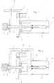
- the plunger pumpcomprises a housing 1 and a pump head 8 fixedly attached to the housing.
- the pumping mediumfor example an oil or an inert liquid for the biological material to be collected.
- the working spaceis elongated in the present embodiment and a syringe similar and has at one end an inlet and outlet port through which pumping medium is sucked or ejected.
- a plunger (plunger) 7is introduced via a seal, which can move axially (ie, along the longitudinal extent of the working space) in the working space and displaces the corresponding volume of the fluid in the working space by its own volume. In other words, by reciprocating the plunger 7, the available volume of the working space can be changed.
- a threaded spindle 5At its end facing away from the working space of the plunger 7 is connected to a threaded spindle 5, said connection in FIG. 1 is rigidly shown, but can also be freely rotatable about a bearing.
- the threaded spindle 5which is mounted in an axially movable support 12 in the housing, is also arranged displaceable relative to the housing and engages via its thread with a spindle nut 6, which is immovable, but rotatably mounted in the housing 1 (or in the pump head 8) ,
- the spindle nut 6is in turn with the Shaft of an electric motor 2 in threaded engagement and is driven by this for rotation.
- a handwheel 3 for manually driving the pumpis provided at the end of the threaded spindle 5 remote from the plunger 7, a handwheel 3 for manually driving the pump is provided.
- slip clutch 4between the handwheel 3 and the holder 12, which counteracts, for example, by the spring force of a wave washer a rotation of the handwheel 3 and thus the threaded spindle 5 and prevented in normal operation.
- the spindle nut 6is rotated by the electric motor 2 in rotation, and this rotation of the non-displaceable spindle nut 6 is converted into a longitudinal movement of the non-rotating (locked) threaded spindle 5, which in turn shifts the plunger 7 of the pump axially in the working space.
- the direct drive of the threaded nut 6can thus a very accurate and controllable displacement of the plunger 7 are obtained, which corresponds to a very well-defined volume change in the nanoliter range.
- a precisely defined flow of pumping mediumcan be created by which individual cells or cell constituents can be separated and collected.
- the plunger pumpcan be actuated via the handwheel 3.
- the motor 2 and the rotation of the spindle nut 6are stopped.
- the locking effect of the slip clutch 4is overcome and the threaded spindle 5 is rotated in the housing. Since the motor 2 is turned off and the spindle nut 6 is not rotating (locked), the threaded spindle 5 screws through the nut 6 and moves the plunger 7 in the axial direction in the working space 9.
- FIG. 2A second embodiment of the plunger pump according to the invention is in FIG. 2 shown.
- the threaded spindle 5is not directly, ie translationally, coupled to the plunger 7.
- the plunger 7is connected via a roller bearing with the spindle nut 6, which is arranged axially movable together with its drive motor 2 in the housing 1, that is not fixed to the housing 1, and thus axially displaced together with the plunger.
- the threaded spindle 5, however,is mounted translationally fixed to the housing 1 and fixed in rotation via a friction clutch.
- the spindle nut 6rotates and thus moves axially on the threaded spindle 5 rotatably fixed by the friction clutch.
- the spindle nut 6also moves the plunger 7 in the axial direction in the working space 9.
- FIG. 2described embodiments, an excessive moment of force acting on the threaded spindle 5, the slip clutch 4 slides through and allows the rotation of the threaded spindle 5, so that the traslatorische movement of the spindle nut 6 is stopped. In this way it is ensured that the sensitive mechanism of the plunger pump is not damaged due to operating errors or other circumstances.
Landscapes
- Engineering & Computer Science (AREA)
- Health & Medical Sciences (AREA)
- Mechanical Engineering (AREA)
- General Engineering & Computer Science (AREA)
- Hematology (AREA)
- General Health & Medical Sciences (AREA)
- Biomedical Technology (AREA)
- Heart & Thoracic Surgery (AREA)
- Vascular Medicine (AREA)
- Life Sciences & Earth Sciences (AREA)
- Animal Behavior & Ethology (AREA)
- Anesthesiology (AREA)
- Public Health (AREA)
- Veterinary Medicine (AREA)
- Power Engineering (AREA)
- Reciprocating Pumps (AREA)
- Transmission Devices (AREA)
- Apparatus Associated With Microorganisms And Enzymes (AREA)
- Sampling And Sample Adjustment (AREA)
Description
Translated fromGermanDie vorliegende Erfindung betrifft eine hochpräzise Plungerpumpen mit manueller Eingriffsmöglichkeit für Volumen unter einem Mikroliter gemäß dem Oberbegriff des Anspruchs 1.The present invention relates to a high-precision plunger pumps with manual intervention for volumes below one microliter according to the preamble of claim 1.
Die molekulare Analyse reiner angereicherter Zellkulturen oder sogar einzelner Zellen ist eine wichtige Voraussetzung der medizinischen Genomik und Proteomik, und könnte in Zukunft für eine medizinische Profilierung von Patienten von wesentlicher Bedeutung werden. Bisher war dieses Ziel aufgrund maschineller sowie verfahrenstechnischer Beschränkungen bei der Zellmanipulation (z.B. der Zellsammlung oder der Mikroinjektion) nur schwer und mit nicht unerheblichem Zeitaufwand zu erreichen. Insbesondere die zur genotypischen und phaenotypischen Charakterisierung notwendige Isolierung einzelner sowie seltener Zellen aus winzigen Proben stellte sich sehr schwierig dar, da einzelne Zellen vom Forschungspersonal unter einem Mikroskop erfasst und die erfasste Zelle dann manuell mithilfe von Kapillaren manipuliert werden musste. Hierzu ist es notwendig, in den Kapillaren ein genau definiertes Fluidvolumen zu bewegen, beispielsweise um einzelne Zellen oder Zellinhalte über die Kapillare zu entnehmen oder in eine Zelle Bestandteile anderer Zellen (zum Beispiel Zellkerne) zu injizieren, ohne dabei die Zelle durch zu viel abgesaugtes oder injiziertes Material zu beschädigen.Molecular analysis of pure enriched cell cultures or even single cells is an important prerequisite of medical genomics and proteomics, and may become essential in the future for medical profiling of patients. Previously, this goal was difficult and time-consuming to achieve due to mechanical as well as procedural limitations in cell manipulation (e.g., cell collection or microinjection). In particular, the isolation of individual and rare cells from tiny samples, which was necessary for genotypic and phenotypic characterization, proved to be very difficult since individual cells had to be detected under a microscope by the research staff and the detected cell then had to be manipulated manually using capillaries. For this purpose, it is necessary to move in the capillaries a well-defined fluid volume, for example, to remove individual cells or cell contents through the capillary or to inject into a cell components of other cells (for example, cell nuclei), without the cell by too much aspirated or damaging injected material.
Eine der oben genannten Beschränkungen betrifft insbesondere die zur Volumenabmessung und Bereitstellung des Unter-/Überdrucks eingesetzten Pumpen, die in der Lage sein müssen, mit hoher Präzision Fluid-Volumina der Größenordnung von weniger als einem Mikroliter bis hinab zu einem Nanoliter anzusaugen bzw. auszustoßen. Da aufgrund der kleinen Pumpvolumina und der somit kleinen Pumpenabmessungen die bei Kolbenpumpen nötige Abdichtung des Pumpenkolbens gegenüber dem Pumpenzylinder nur schlecht möglich ist, werden in der Manipulation von Zellmaterial sogenannte Plungerpumpen eingesetzt, bei denen der Plunger lediglich an der Stelle, an der er in den Zylinder eindringt, abgedichtet werden muss.In particular, one of the above-mentioned limitations relates to pumps used for volumetric measurement and pressurization, which must be capable of delivering, with high precision, fluid volumes on the order of less than one microliter down to one nanoliter suck in or expel. Since due to the small pump volumes and thus small pump dimensions necessary for piston pumps sealing the pump piston against the pump cylinder is poorly possible in the manipulation of cell material so-called plunger pumps are used in which the plunger only at the point at which he into the cylinder penetrates, must be sealed.
Um die oben beschriebene Präzision der Volumina bei gleichzeitiger Koordination mit der Zellerfassung unter dem Mikroskop beizubehalten, wird die Erfassung sowie Manipulation der Zellen zum Teil weiterhin manuell betrieben, beispielsweise mit den CellTram-Mikroinjektoren der Firma Eppendorf oder den XenoWorks™-Mikroinjektoren der Firma Butter Instrument, bei denen der Plunger durch Drehen eines Handrads betätigt wird. Ein derartiges manuelles Vorgehen bei der Zellmanipulation ist natürlich äußerst zeitintensiv und eignet sich somit immer weniger für die stetig zunehmende Anzahl an zu verarbeitenden Proben, nicht zuletzt aufgrund der nötigen Personalkosten.In order to maintain the above-described precision of the volumes while co-ordinating with the cell detection under the microscope, the detection and manipulation of the cells is still partly operated manually, for example with the Eppendorf CellTram microinjectors or the Buttero XenoWorks ™ microinjectors in which the plunger is actuated by turning a handwheel. Such a manual procedure in the cell manipulation is of course extremely time-consuming and is thus less and less suitable for the steadily increasing number of samples to be processed, not least because of the necessary personnel costs.
Andererseits ist bekannt, die eben genannten manuellen Pumpen über einen am Handrad angekoppelten Antriebsmotor zu betreiben. Ein weiterer Versuch der Automation des Manipulationssystems wurde mit den Mikroinjektionspipetten Nanoject II der Firma Drummond Science unternommen, bei denen der Plunger direkt an einen mikroprozessorgesteuerten Elektromotor gekoppelt ist. Bei den genannten motorisierten Pumpen besteht allerdings das Problem, dass ihre Antriebe sehr langsam sind und somit Serviceeingriffe, wie beispielsweise das bei jedem Kapillarenwechsel notwendige "Backfilling" mit Fluid, sehr zeitraubend oder sogar unmöglich sind. Auch ist es nicht möglich, die motorisierten Pumpen hierzu auf einfache Weise von Hand zu betreiben, da im Falle der motorisierten Handpumpe der Motor zuerst aufwändig entkoppelt werden muss, während bei der automatisierten Mikroinjektionspipette eine manuelle Betätigung überhaupt nicht vorgesehen ist.On the other hand, it is known to operate the just mentioned manual pumps via a drive motor coupled to the handwheel. Another attempt at automation of the manipulation system was made with the Nanoject II microinjection pipettes from Drummond Science, in which the plunger is coupled directly to a microprocessor-controlled electric motor. The problem with the mentioned motorized pumps, however, is that their drives are very slow and thus service interventions, such as the "backfilling" with fluid required with every capillary change, are very time-consuming or even impossible. Also, it is not possible to operate the motorized pumps for this purpose in a simple manner by hand, since in the case of the motorized hand pump, the engine must first be laboriously decoupled, while in the automated Microinjection pipette manual operation is not provided.
Die Druckschriften
Es ist somit eine Aufgabe der vorliegenden Erfindung, eine automatisierte Plungerpumpe für Volumen unter einem Mikroliter bereitzustellen, die sowohl automatisch als auch manuell betrieben werden kann, manuelleIt is thus an object of the present invention to provide an automated plunger pump for volumes below one microliter, which can be operated both automatically and manually, manual
Eingriffsmöglichkeiten zur Befüllung bzw. Wartung ermöglicht und bei hoher Volumenpräzision mechanisch unempfindlich ist. Diese Aufgabe wird mithilfe einer automatisierten hochpräzisen Plungerpumpe gelöst, die die in Anspruch 1 definierten Merkmale umfasst. Weitere vorteilhafte Ausführungsformen ergeben sich aus den Unteransprüchen.Possibility of intervention for filling or maintenance and is mechanically insensitive at high volume precision. This object is achieved by means of an automated high-precision plunger pump comprising the features defined in claim 1. Further advantageous embodiments will become apparent from the dependent claims.
Die erfindungsgemäße automatisierte hochpräzise Plungerpumpe umfasst ein Gehäuse und einen Pumpkopf, der einen Arbeitsraum mit einer gemeinsamen oder separaten Ein- und Auslassöffnung definiert, wobei das Volumen des Arbeitsraums durch einen in ihn einbringbaren axial beweglichen Plunger veränderbar ist und der Plunger durch eine Gewindespindel oder eine auf der Gewindespindel in Gewindeeingriff befindliche Spindelmutter axial beweglich ist, und die Gewindespindel und/oder die Spindelmutter rotatorisch antreibbar ist. Die jeweils andere (Spindelmutter bzw. Gewindespindel) ist mithilfe einer Kupplung (4) rotatorisch arretierbar ausgelegt.The automated high-precision plunger pump according to the invention comprises a housing and a pump head, which defines a working space with a common or separate inlet and outlet opening, wherein the volume of the working space is changeable by an axially movable plunger insertable into it and the plunger by a threaded spindle or on the threaded spindle in threaded engagement located spindle nut is axially movable, and the threaded spindle and / or the spindle nut is rotationally driven. The other one (spindle nut or threaded spindle) is designed to be rotatable locked by means of a coupling (4).
Durch diesen Aufbau besitzt die erfindungsgemäße Plungerpumpe zwei mechanisch voneinander abkoppelbare Antriebsstränge, da die axiale Bewegung des Plungers entweder durch Antrieb der Gewindespindel oder durch Antrieb der Spindelmutter unabhängig vom jeweils anderen Antriebsstrang bewirkt werden kann. Um den Plunger beispielsweise zum Nachfüllen der Pumpe zu bewegen, ist es somit nicht mehr notwendig, wie im Stand der Technik einen Antriebsstrang aufwändig zu entkoppeln, und es kann aufgrund der direkten Ankopplung des Antriebs an der Gewindemutter eine ebenso präzise wie zu Service- oder Wartungszwecken einfach bedienbare Pumpe bereitgestellt werden. Derartige Service- und Wartungseingriffe sind hierbei nicht nur auf das Nachfüllen von Pumpmedium beschränkt, sondern umfassen unter anderem auch das Spülen oder Reinigen des Arbeitsraumes bzw. der daran anschließbaren Kapillare/Pipette. Es handelt sich bei diesen Eingriffe also um relativ häufig durchzuführende Tätigkeiten, die nun dank der schnelleren und einfacheren Bedienung der Pumpe wesentlich weniger Zeit in Anspruch nehmen. Außerdem stellt die Kupplung ein Sicherheitselement dar und verhindert mechanische Beschädigungen am empfindlichen Antriebsstrang und Motor der Pumpe, sollte es zu übermäßigen Belastungen in der Pumpe kommen, beispielsweise durch Eindringen eines Fremdkörpers in den Arbeitsraum oder durch Fehlbedienung seitens des Benutzers. Die Kupplung kann dabei manuell oder aber auch automatisiert sein.By virtue of this design, the plunger pump according to the invention has two drive trains which can be decoupled from one another mechanically, since the axial movement of the plunger is achieved either by driving the plunger Threaded spindle or by driving the spindle nut can be effected independently of each other's powertrain. In order to move the plunger, for example, to refill the pump, it is thus no longer necessary to costly decouple a drive train as in the prior art, and it can due to the direct coupling of the drive to the threaded nut as precise as for service or maintenance purposes easy to use pump can be provided. Such service and maintenance interventions here are not limited to the refilling of pumping medium, but include, among other things, the rinsing or cleaning of the working space or the connectable capillary / pipette. These interventions are thus relatively frequent activities that now take much less time thanks to the faster and easier operation of the pump. In addition, the coupling is a safety element and prevents mechanical damage to the sensitive drive train and motor of the pump, should it be excessive loads in the pump, for example, by penetration of a foreign body into the workspace or by misuse by the user. The coupling can be manual or automated.
Insgesamt stellt die Erfindung also eine Plungerpumpe bereit, die mit geringem mechanischen Aufwand eine schnelle, effiziente und somit Kosten senkende Mikromanipulation von biologischem Material ermöglicht, die sich durch Zuverlässigkeit und Sicherheit der mechanischen Teile auszeichnet und die eine herausragende Bedienerfreundlichkeit besitzt, da der Anwender die Möglichkeit hat, in den Prozess der Zellsammlung einzugreifen.Overall, the invention thus provides a plunger pump that enables a fast, efficient and thus cost-reducing micromanipulation of biological material with low mechanical complexity, which is characterized by reliability and safety of the mechanical parts and has an outstanding user-friendliness, since the user has the opportunity has to intervene in the process of cell collection.
Bevorzugt umfasst dabei die Plungerpumpe als Antrieb einen Motor, der mit der Spindelmutter und/oder der Gewindespindel in Eingriff steht und über sie mit der rotatorisch arretierten Gewindespindel bzw. der rotatorisch arretierten Spindelmutter zum Antrieb des Plungers in Wirkverbindung steht. Wird beispielsweise die Spindelmutter, die drehbar im Gehäuse eingebaut ist, vom Motor angetrieben, so wird die rotatorisch arretierte Gewindespindel, die mit der Spindelmutter in Gewindeeingriff steht, in axialer Richtung bewegt, wodurch auch der mit der Gewindespindel verbundene Plunger bewegt wird und das Volumen des Arbeitsraums der Pumpe verändert.Preferably, the plunger pump comprises as a drive a motor which is in engagement with the spindle nut and / or the threaded spindle and is operatively connected therewith to the rotationally locked threaded spindle or the rotationally locked spindle nut for driving the plunger. For example, if the spindle nut, the rotatable in Housing is mounted, driven by the motor, the rotatably locked threaded spindle, which is in threaded engagement with the spindle nut, moves in the axial direction, which also moves the plunger connected to the threaded spindle and changes the volume of the working chamber of the pump.
In einer bevorzugten Ausgestaltung sind die Gewindespindel und/oder die Spindelmutter mit einem vorgeschalteten Getriebe versehen. Dadurch ist es möglich, die axiale Verschiebung des Plungers optimal an die bevorzugte Drehzahl des Motors anzupassen und in Funktion davon zu ändern. Andererseits kann ein derartiges Getriebe (zum Beispiel ein Planetengetriebe) auf einfache Weise einen manuellen Eingriff ermöglichen, das heißt Eingriffspunkte für eine manuelle Drehung des Getriebes bieten, die dann in eine Bewegung des Plungers umgesetzt wird. Als weitere Option könnte auch die im Handantrieb betätigte Gewindespindel mit einer entsprechenden Übersetzung motorisiert werden.In a preferred embodiment, the threaded spindle and / or the spindle nut are provided with an upstream transmission. This makes it possible to optimally adjust the axial displacement of the plunger to the preferred speed of the engine and to change in function thereof. On the other hand, such a transmission (for example, a planetary gear) can easily enable a manual intervention, that is to provide intervention points for a manual rotation of the transmission, which is then converted into a movement of the plunger. As another option, the manually operated threaded spindle could be motorized with a corresponding translation.
In einer besonders bevorzugten Ausführungsform der Plungerpumpe ist die Kupplung eine Rutschkupplung.In a particularly preferred embodiment of the plunger pump, the clutch is a slip clutch.
Der Plunger ist vorzugsweise mit der Gewindespindel mitdrehend verbunden, was eine einfach und kostengünstig zu realisierende Verbindung darstellt. Dies kann zum Beispiel durch einen (lösbaren) Reibschluß zwischen Plunger und Gewindespindel erreicht werden. Insbesondere kann dabei der Plunger auch drehstarr mit der Gewindespindel verbunden sein, was seinen Vorteil darin hat, dass der Plunger sich nicht in der notwendigen Dichtung dreht und somit ein Verschleiß der Dichtung verringert wird.The plunger is preferably co-rotating with the threaded spindle, which is a simple and inexpensive to implement connection. This can be achieved for example by a (releasable) friction between plunger and threaded spindle. In particular, the plunger can also be torsionally rigidly connected to the threaded spindle, which has its advantage in that the plunger does not rotate in the necessary seal and thus wear of the seal is reduced.
In einer weiteren vorteilhaften Ausführungsform der Plungerpumpe ist der Pumpkopf mit in den Arbeitsraum führenden, bevorzugt richtungsorientierten Ventilen versehen. Dies erleichtert zusätzlich das Nachfüllen vom Pumpmedium, und die Richtungsorientierung, beispielsweise in Form eines Rückschlagventils, verhindert dabei einen unerwünschten Austritt des Pumpmediums.In a further advantageous embodiment of the plunger pump of the pump head is provided with leading into the working space, preferably directional valves. This additionally facilitates the refilling of the pumping medium, and the directional orientation, for example in the form of a Check valve, thereby preventing unwanted leakage of the pumping medium.
Schließlich ist es vorteilhaft, im Pumpenkopf Endschalter vorzusehen, die die Endlagen des Plungers im Arbeitsraum angeben. Diese Endschalter können mit einer Steuerung verbunden werden, die sicherstellt, dass der Plunger nicht an die axialen Endwand des Arbeitsraums stößt bzw. die Gewindespindel oder die Spindelmutter über ihre Endpositionen hinaus verschoben oder gedreht werden.Finally, it is advantageous to provide limit switches in the pump head, which indicate the end positions of the plunger in the working space. These limit switches can be connected to a controller which ensures that the plunger does not hit the axial end wall of the working space or that the threaded spindle or the spindle nut is displaced or rotated beyond its end positions.
Figur 1 ist eine schematische Schnittansicht einer ersten Ausführungsform der automatisierten hochpräzisen Plungerpumpe gemäß der Erfindung; undFIG. 1 Fig. 12 is a schematic sectional view of a first embodiment of the automated high-precision plunger pump according to the invention; andFigur 2 ist eine schematische Schnittansicht einer zweiten Ausführungsform der automatisierten hochpräzisen Plungerpumpe gemäß der Erfindung.FIG. 2 is a schematic sectional view of a second embodiment of the automated high-precision plunger pump according to the invention.
Im Folgenden werden bevorzugte Ausführungsformen der vorliegenden Erfindung unter Bezugnahme auf die Zeichnungen beschrieben. Zunächst wird zum besseren Verständnis des Einsatzbereichs der Erfindung die automatisierte Isolierung beliebiger einzelner oder seltener Zellen beschrieben, welche in drei Schritten abläuft: Zellerkennung; Zellsammlung und Zellabgabe.Hereinafter, preferred embodiments of the present invention will be described with reference to the drawings. First, to better understand the field of application of the invention, the automated isolation of any single or rare cells will be described, which proceeds in three steps: cell recognition; Cell collection and cell delivery.
Die Erfinder haben zu diesem Zweck ein System bereitgestellt, das auf einem inversen Mikroskop (Umkehrmikroskop), einer Zellerkennungseinheit, einer automatisierten Kapillarverstellung, einer automatisierten Pumpe und einem Verschiebetisch basiert. Die Sammlung und Abgabe werden mithilfe einer (im Folgenden detailliert beschriebenen) hochpräzisen Pumpe gesteuert, die es erlaubt, Verfahrensabläufe festzulegen, die Nanoliter-Volumen eines Pumpmediums für den Abtrennvorgang der Zelle einsetzen und so die Grundlage schaffen für eine am Verfahrensende durchzuführende molekulare Analyse des Zellmaterials in lediglich 1 Microliter Medium.The inventors have provided for this purpose a system based on an inverted microscope (reverse microscope), a cell recognition unit, an automated capillary adjustment, an automated pump and a translation stage. Collection and dispensing will be done by means of a (described in detail below) controlled high-precision pump, which allows to set procedures that use nanoliter volumes of a pumping medium for the separation process of the cell and thus provide the basis for a process to be carried out molecular analysis of the cell material in only 1 microliter of medium.
Die (nicht-haftenden) Zellen erfahren dabei keinerlei mechanische Belastungen: die Zellsammlung erfolgt lediglich aufgrund des die Zelle umgebenden Flüssligkeitsflusses. Unter optimalen Bedingungen können selbst teilweise anhaftende Zellen auf diese Weise gesammelt werden. Es besteht kein Kontakt zwischen den Zellen und der zur Sammlung eingesetzten Kapillare. Der Kapillardurchmesser kann wesentlich größer sein als jener der Zelle. Zum Beispiel können Zellen mit 6 µm Durchmesser effizient mit einer Kapillare von 40 µm Durchmesser gesammelt werden.The (non-adherent) cells experience no mechanical stress: the cell collection takes place only due to the liquid flow surrounding the cell. Under optimal conditions, even partially adherent cells can be collected in this way. There is no contact between the cells and the capillary used for collection. The capillary diameter can be much larger than that of the cell. For example, cells of 6 μm diameter can be collected efficiently with a capillary of 40 μm diameter.
Die Abgabe der Zellen kann auf verschiedene Zielträger (deposits) erfolgen. Sogenannte "Grid deposits" sind dabei entweder raster-artige Punktablagen (wie zum Beispiel AmpliGrid®) oder raster-artig angeordnete kleine Behälter (wie die IBIDI Probentaschen-Objektträger). Einzelpunktablagen können aus einem transparenten Deckel, einem PCR-Röhrchen oder einer Mikrofluid-Vorrichtung bestehen. Wie auch immer der Zielträger beschaffen ist, seine Größe sollte im Allgemeinen nicht die Größe von Standard-Objektträgern überschreiten, damit diese in die Mehrfachhalterung der Objektträger auf dem Verschiebetisch eingesetzt werden können.The delivery of the cells can take place on different target deposits. So-called "grid deposits" are either raster-type dot trays (such as AmpliGrid®) or raster-like arranged small containers (such as the IBIDI sample pocket slides). Single point trays may consist of a transparent lid, a PCR tube or a microfluidic device. Whatever the target carrier is, its size should generally not exceed the size of standard slides so that they can be inserted into the multiple support slides on the translation stage.
Die Sammlung und Abgabe der Zellen kann auf verschiedene Arten erfolgen: von der manuellen bis zur voll automatisierten Betriebsart mit Zellerkennung. Jedoch ist es selbst bei der manuellen Betriebsart nicht notwendig, irgendeine Komponente des Systems (Mikroskop, Pumpe, Kapillare) von Hand zu bedienen: alle Betriebsvorgänge werden durch den Benutzer vom PC aus gestartet.The collection and delivery of cells can be done in several ways: from manual to fully automated cell recognition mode. However, even in the manual mode, it is not necessary to use any component of the system (microscope, pump, Capillary) by hand: all operations are started by the user from the PC.
Anhand der
Am anderen Ende des länglichen Arbeitsraum 9 ist über eine Dichtung ein Plunger (Tauchkolben) 7 eingeführt, der sich im Arbeitsraum axial (d.h. entlang der Längsausdehnung des Arbeitsraums) bewegen kann und durch sein eigenes Volumen das entsprechende Volumen des im Arbeitsraum befindlichen Fluids verdrängt. In anderen Worten kann durch Hin- und Herbewegen des Plungers 7 das verfügbare Volumen des Arbeitraums verändert werden. An seinem dem Arbeitsraum abgewandten Ende ist der Plunger 7 mit einer Gewindespindel 5 verbunden, wobei diese Verbindung in
Die Gewindespindel 5, die in einer im Gehäuse axial beweglichen Halterung 12 gelagert ist, ist relativ zum Gehäuse ebenfalls verschiebbar angeordnet und greift über ihr Gewinde mit einer Spindelmutter 6 ein, welche unverschieblich, aber drehbar im Gehäuse 1 (oder im Pumpkopf 8) gelagert ist. Die Spindelmutter 6 steht ihrerseits mit der Welle eines Elektromotors 2 in Gewindeeingriff und wird von diesem zur Drehung angetrieben. Zudem ist am vom Plunger 7 entfernten Ende der Gewindespindel 5 ein Handrad 3 zum manuellen Antrieb der Pumpe vorgesehen.The threaded
Zwischen dem Handrad 3 und der Halterung 12 befindet sich eine Rutschkupplung 4, welche beispielsweise durch die Federkraft einer Wellenscheibe einer Rotation des Handrads 3 und damit der Gewindespindel 5 entgegenwirkt und im Normalbetrieb verhindert.There is a
Im Betrieb wird also die Spindelmutter 6 durch den Elektromotor 2 in Drehung versetzt, und diese Drehung der unverschieblichen Spindelmutter 6 wird in eine Längsbewegung der nicht rotierenden (arretierten) Gewindespindel 5 umgewandelt, welche wiederum den Plunger 7 der Pumpe axial im Arbeitsraum verschiebt. Durch den direkten Antrieb der Gewindemutter 6 kann damit eine sehr genaue und kontrollierbare Verschiebung des Plungers 7 erhalten werden, die einer sehr genau definierten Volumenänderung im Nanoliter-Bereich entspricht. Mit dieser sehr genauen Volumenänderung lässt sich wiederum ein exakt definierter Fluss an Pumpmedium erzeugen, mithilfe dessen einzelne Zellen oder Zellbestandteile abgetrennt und gesammelt werden können.In operation, therefore, the
Sollte es im Betrieb notwendig sein, den Fluidfluss bzw. das Pumpvolumen zu korrigieren oder das Pumpmedium nachzufüllen, so kann die Plungerpumpe über das Handrad 3 betätigt werden. Dabei wird zunächst der Motor 2 und die Drehung der Spindelmutter 6 gestoppt. Durch Drehung des Handrads 3 wird die arretierende Wirkung der Rutschkupplung 4 überwunden und die Gewindespindel 5 im Gehäuse gedreht. Da der Motor 2 ausgeschaltet ist und sich die Spindelmutter 6 nicht dreht (arretiert ist), schraubt sich die Gewindespindel 5 durch die Mutter 6 und bewegt den Plunger 7 in axialer Richtung im Arbeitsraum 9.Should it be necessary during operation to correct the fluid flow or the pumping volume or to refill the pumping medium, the plunger pump can be actuated via the
Eine zweite Ausführungsform der erfindungsgemäßen Plungerpumpe ist in
Sollte bei den Plungerpumpen der beiden in
Claims (9)
- Automated high-precision plunger pump for volumes under a microlitre, comprisinga housing (1) and a pump head (8) which defines a work chamber (9) having a common or separate inlet and outlet openings (10), wherein the volume of the work chamber (9) is variable by an axially movable plunger (7) which can be introduced into it,the plunger (7) is axially movable by a threaded spindle (5) or a spindle nut (6) which is located in threaded engagement on the threaded spindle (5), andthe threaded spindle (5) and/or the spindle nut (6) is rotationally drivable,characterised in that the other one is designed to be rotationally lockable by means of a clutch (4).
- Plunger pump according to claim 1, wherein the plunger pump comprises a motor (2) which is engaged with the spindle nut (6) and/or the threaded spindle (5) and is operatively connected by it to the rotationally locked threaded spindle (5) or the rotationally locked spindle nut (6) for driving the plunger (7).
- Plunger pump according to claim 1 or 2, wherein the threaded spindle (5) and/or the spindle nut (6) is provided with an upstream gearbox.
- Plunger pump according to claim 1, 2 or 3, wherein the clutch (4) is a sliding clutch.
- Plunger pump according to any of the preceding claims, wherein the clutch (4) is manual or automated.
- Plunger pump according to any of the preceding claims, wherein the spindle nut (5) is mounted relative to the housing (1) or relative to the plunger (7) by means of a rolling bearing (13) which is preloaded without play.
- Plunger pump according to any of the preceding claims, wherein the plunger (7) is connected to the threaded spindle (5) to rotate with it, in particular with torsional rigidity.
- Plunger pump according to any of the preceding claims, wherein the pump head is provided with valves which lead into the work chamber and are preferably directionally oriented.
- Plunger pump according to any of the preceding claims, wherein limit switches which indicate the end positions of the plunger (7) in the work chamber (9) are provided in the pump head (8).
Priority Applications (1)
| Application Number | Priority Date | Filing Date | Title |
|---|---|---|---|
| EP11713822.2AEP2558721B1 (en) | 2010-04-15 | 2011-04-12 | Plunger pump with manual intervention possibility for volumes under one microliter |
Applications Claiming Priority (3)
| Application Number | Priority Date | Filing Date | Title |
|---|---|---|---|
| EP10160010AEP2378119A1 (en) | 2010-04-15 | 2010-04-15 | Plunger pump with manual insertion possibility for volumes under a microlitre |
| EP11713822.2AEP2558721B1 (en) | 2010-04-15 | 2011-04-12 | Plunger pump with manual intervention possibility for volumes under one microliter |
| PCT/EP2011/055698WO2011141253A1 (en) | 2010-04-15 | 2011-04-12 | Plunger pump for volumes below one microliter, allowing manual intervention |
Publications (2)
| Publication Number | Publication Date |
|---|---|
| EP2558721A1 EP2558721A1 (en) | 2013-02-20 |
| EP2558721B1true EP2558721B1 (en) | 2017-01-11 |
Family
ID=42280085
Family Applications (2)
| Application Number | Title | Priority Date | Filing Date |
|---|---|---|---|
| EP10160010AWithdrawnEP2378119A1 (en) | 2010-04-15 | 2010-04-15 | Plunger pump with manual insertion possibility for volumes under a microlitre |
| EP11713822.2AActiveEP2558721B1 (en) | 2010-04-15 | 2011-04-12 | Plunger pump with manual intervention possibility for volumes under one microliter |
Family Applications Before (1)
| Application Number | Title | Priority Date | Filing Date |
|---|---|---|---|
| EP10160010AWithdrawnEP2378119A1 (en) | 2010-04-15 | 2010-04-15 | Plunger pump with manual insertion possibility for volumes under a microlitre |
Country Status (4)
| Country | Link |
|---|---|
| US (1) | US9366241B2 (en) |
| EP (2) | EP2378119A1 (en) |
| JP (1) | JP5855087B2 (en) |
| WO (1) | WO2011141253A1 (en) |
Families Citing this family (10)
| Publication number | Priority date | Publication date | Assignee | Title |
|---|---|---|---|---|
| DE102013112287B4 (en)* | 2013-11-08 | 2019-07-11 | Dionex Softron Gmbh | sampler |
| SG10201906471PA (en) | 2015-01-14 | 2019-09-27 | Brigham & Womens Hospital Inc | Treatment of cancer with anti-lap monoclonal antibodies |
| CN105114296B (en)* | 2015-08-07 | 2019-07-30 | 三一石油智能装备有限公司 | A kind of fracturing pump and its plunger position adjust device |
| CN105673378A (en)* | 2016-01-13 | 2016-06-15 | 江苏汉龙环保科技有限公司 | Two-way metering pump system |
| EP3339424B1 (en)* | 2016-12-23 | 2019-05-22 | Eppendorf AG | Manual injector for cell manipulation |
| CN106975125A (en)* | 2017-04-28 | 2017-07-25 | 黄河科技学院 | A kind of disposable adjustable syringe |
| EP3505232B1 (en)* | 2017-12-28 | 2025-04-30 | Satisloh AG | Coating system with a device for mixing and/or dosing liquid coating materials and method for coloring optical glasses |
| US11229905B2 (en)* | 2018-05-23 | 2022-01-25 | Vistalab Technologies, Inc. | Method and apparatus for dispensing precise aliquots of liquid |
| CN112175806B (en)* | 2020-08-26 | 2023-07-21 | 德州职业技术学院(德州市技师学院) | Microorganism sampling and storing integrated container |
| CN114278528B (en)* | 2021-12-23 | 2024-01-30 | 苏州绿的谐波传动科技股份有限公司 | Miniature high-response control pump |
Family Cites Families (24)
| Publication number | Priority date | Publication date | Assignee | Title |
|---|---|---|---|---|
| US638077A (en)* | 1899-11-28 | Frank thompson | ||
| CH447637A (en)* | 1964-09-18 | 1967-11-30 | Ceskoslovenska Akademie Ved | Device for precise dosing of liquids |
| US3631847A (en)* | 1966-03-04 | 1972-01-04 | James C Hobbs | Method and apparatus for injecting fluid into the vascular system |
| US3415419A (en)* | 1966-10-27 | 1968-12-10 | Jewett | Fluid administering system |
| DE2442622C2 (en)* | 1974-09-05 | 1976-11-11 | Dr.-Ing. Kieback & Peter Spezialfabrik für selbsttätige Regler, 1000 Berlin | MOTOR AND MANUAL ADJUSTABLE SCREW GEAR |
| US4406158A (en)* | 1981-09-09 | 1983-09-27 | Isco, Inc. | Apparatus and method for temperature correction of liquid chromatography |
| DE3150623C2 (en)* | 1981-12-21 | 1983-12-01 | B. Braun Melsungen Ag, 3508 Melsungen | Pressure infusion apparatus for medical applications |
| GB2229497B (en)* | 1989-03-10 | 1992-06-03 | Graseby Medical Ltd | Infusion pump |
| EP0514907B1 (en)* | 1991-05-23 | 1996-07-10 | Ivac Corporation | Syringe plunger driver system |
| US5219099A (en)* | 1991-09-06 | 1993-06-15 | California Institute Of Technology | Coaxial lead screw drive syringe pump |
| US5738728A (en)* | 1996-07-26 | 1998-04-14 | Bio Dot, Inc. | Precision metered aerosol dispensing apparatus |
| USRE38281E1 (en)* | 1996-07-26 | 2003-10-21 | Biodot, Inc. | Dispensing apparatus having improved dynamic range |
| US7193521B2 (en)* | 1998-10-29 | 2007-03-20 | Medtronic Minimed, Inc. | Method and apparatus for detecting errors, fluid pressure, and occlusions in an ambulatory infusion pump |
| CA2345439C (en)* | 1998-10-29 | 2005-08-09 | Minimed, Inc. | Compact pump drive system |
| US6475188B1 (en)* | 1999-05-20 | 2002-11-05 | Anthony David Baxter | Bilateral microinjector pump for freely moving animals in an operant chamber |
| US6610030B1 (en)* | 1999-07-20 | 2003-08-26 | Anthony Baxter | Bilateral syringe tethered remote micro-pump |
| US20020022802A1 (en)* | 2000-06-13 | 2002-02-21 | Simpson Frank B. | Wrap spring clutch syringe ram and frit mixer |
| US6387077B1 (en)* | 2000-10-13 | 2002-05-14 | Mallinckrodt Inc. | Apparatus and method for providing a suspended agent |
| US7080936B1 (en)* | 2001-06-13 | 2006-07-25 | Simpson Frank B | Wrap spring clutch syringe ram and frit mixer |
| KR100438777B1 (en) | 2001-11-06 | 2004-07-05 | 삼성전자주식회사 | Hard disk drive comprising flexible printed circuit with hole |
| CN100557963C (en) | 2004-12-15 | 2009-11-04 | Nxp股份有限公司 | Thin film acoustic reflector lamination, manufacturing method and configuration |
| JP2006281178A (en)* | 2005-04-05 | 2006-10-19 | Noiberuku Kk | Syringe pump |
| US7713232B2 (en)* | 2005-11-04 | 2010-05-11 | Medrad, Inc. | System for washing and processing of cells for delivery thereof to tissue |
| JP4831412B2 (en)* | 2006-06-16 | 2011-12-07 | 東京理化器械株式会社 | Syringe pump |
- 2010
- 2010-04-15EPEP10160010Apatent/EP2378119A1/ennot_activeWithdrawn
- 2011
- 2011-04-12EPEP11713822.2Apatent/EP2558721B1/enactiveActive
- 2011-04-12JPJP2013504241Apatent/JP5855087B2/enactiveActive
- 2011-04-12WOPCT/EP2011/055698patent/WO2011141253A1/enactiveApplication Filing
- 2011-04-12USUS13/641,256patent/US9366241B2/enactiveActive
Non-Patent Citations (1)
| Title |
|---|
| None* |
Also Published As
| Publication number | Publication date |
|---|---|
| JP5855087B2 (en) | 2016-02-09 |
| EP2558721A1 (en) | 2013-02-20 |
| US9366241B2 (en) | 2016-06-14 |
| EP2378119A1 (en) | 2011-10-19 |
| US20130064693A1 (en) | 2013-03-14 |
| WO2011141253A1 (en) | 2011-11-17 |
| JP2013523169A (en) | 2013-06-17 |
Similar Documents
| Publication | Publication Date | Title |
|---|---|---|
| EP2558721B1 (en) | Plunger pump with manual intervention possibility for volumes under one microliter | |
| EP2575949B1 (en) | Arrangement of a valve device for controlling a flow of a fluid through a fluid channel | |
| EP3680016B1 (en) | Pipette for use with a pipette tip | |
| EP3434373A1 (en) | Pipette device with functional test and method for performing a functional test for a pipette device | |
| EP2535108B1 (en) | Microfluidic System and method of operating the system | |
| DE102010038414A1 (en) | Pipetting device with throttle point in the pipetting channel | |
| CH687954A5 (en) | A device for dispensing a dose of liquid drug. | |
| EP2532426A2 (en) | Cartridge, centrifuge and method | |
| EP3680017B1 (en) | Pipette for use with a pipette tip | |
| EP2193847A1 (en) | Coaxial needle and pipette device | |
| EP3850217B1 (en) | Combination metering assembly for filling liquid products into containers | |
| EP2156890B1 (en) | Assembly and method for generating, manipulating and analysing compartments | |
| EP1071960B1 (en) | Metering device and method for operating a metering device | |
| DE10349513B4 (en) | experimental apparatus | |
| EP2086689B1 (en) | Valve unit for interrupting or releasing a flow of a medium along a hollow duct, use thereof in a dosing system for the metered discharge of said medium, and method for the metered discharge of a medium | |
| DE102013112287B4 (en) | sampler | |
| DE10257414A1 (en) | Electric motor-driven syringe dispenser, has a pump for driving a working piston-cylinder combination that is coupled to the syringe piston, with the pump driven by an electric motor | |
| WO2011141251A1 (en) | Micromanipulation system comprising a protective system for capillaries | |
| DE102023132501B3 (en) | Dosing device for dosing liquids | |
| EP3746637B1 (en) | Vane motor | |
| EP4241887A1 (en) | Pipetting device | |
| EP2027406B1 (en) | Valve | |
| DE4039971A1 (en) | Adjustable syringe pipette with sepn. of main components from measured liq. - by air cushion adjusted in proportion to liq. vol. to a min. size, for aggressive or biologically active liqs. | |
| EP2101092A1 (en) | Fluid control device for microfluidic systems | |
| EP4630077A1 (en) | Medical fluid pump having a drive head |
Legal Events
| Date | Code | Title | Description |
|---|---|---|---|
| PUAI | Public reference made under article 153(3) epc to a published international application that has entered the european phase | Free format text:ORIGINAL CODE: 0009012 | |
| 17P | Request for examination filed | Effective date:20121115 | |
| AK | Designated contracting states | Kind code of ref document:A1 Designated state(s):AL AT BE BG CH CY CZ DE DK EE ES FI FR GB GR HR HU IE IS IT LI LT LU LV MC MK MT NL NO PL PT RO RS SE SI SK SM TR | |
| DAX | Request for extension of the european patent (deleted) | ||
| GRAP | Despatch of communication of intention to grant a patent | Free format text:ORIGINAL CODE: EPIDOSNIGR1 | |
| INTG | Intention to grant announced | Effective date:20160629 | |
| GRAS | Grant fee paid | Free format text:ORIGINAL CODE: EPIDOSNIGR3 | |
| GRAJ | Information related to disapproval of communication of intention to grant by the applicant or resumption of examination proceedings by the epo deleted | Free format text:ORIGINAL CODE: EPIDOSDIGR1 | |
| GRAL | Information related to payment of fee for publishing/printing deleted | Free format text:ORIGINAL CODE: EPIDOSDIGR3 | |
| GRAP | Despatch of communication of intention to grant a patent | Free format text:ORIGINAL CODE: EPIDOSNIGR1 | |
| GRAA | (expected) grant | Free format text:ORIGINAL CODE: 0009210 | |
| INTG | Intention to grant announced | Effective date:20161125 | |
| INTG | Intention to grant announced | Effective date:20160629 | |
| AK | Designated contracting states | Kind code of ref document:B1 Designated state(s):AL AT BE BG CH CY CZ DE DK EE ES FI FR GB GR HR HU IE IS IT LI LT LU LV MC MK MT NL NO PL PT RO RS SE SI SK SM TR | |
| REG | Reference to a national code | Ref country code:GB Ref legal event code:FG4D Free format text:NOT ENGLISH | |
| REG | Reference to a national code | Ref country code:CH Ref legal event code:EP | |
| REG | Reference to a national code | Ref country code:AT Ref legal event code:REF Ref document number:861554 Country of ref document:AT Kind code of ref document:T Effective date:20170115 | |
| REG | Reference to a national code | Ref country code:IE Ref legal event code:FG4D Free format text:LANGUAGE OF EP DOCUMENT: GERMAN | |
| REG | Reference to a national code | Ref country code:DE Ref legal event code:R096 Ref document number:502011011506 Country of ref document:DE | |
| REG | Reference to a national code | Ref country code:FR Ref legal event code:PLFP Year of fee payment:7 | |
| REG | Reference to a national code | Ref country code:LT Ref legal event code:MG4D | |
| REG | Reference to a national code | Ref country code:NL Ref legal event code:MP Effective date:20170111 | |
| PG25 | Lapsed in a contracting state [announced via postgrant information from national office to epo] | Ref country code:NL Free format text:LAPSE BECAUSE OF FAILURE TO SUBMIT A TRANSLATION OF THE DESCRIPTION OR TO PAY THE FEE WITHIN THE PRESCRIBED TIME-LIMIT Effective date:20170111 | |
| PG25 | Lapsed in a contracting state [announced via postgrant information from national office to epo] | Ref country code:HR Free format text:LAPSE BECAUSE OF FAILURE TO SUBMIT A TRANSLATION OF THE DESCRIPTION OR TO PAY THE FEE WITHIN THE PRESCRIBED TIME-LIMIT Effective date:20170111 Ref country code:IS Free format text:LAPSE BECAUSE OF FAILURE TO SUBMIT A TRANSLATION OF THE DESCRIPTION OR TO PAY THE FEE WITHIN THE PRESCRIBED TIME-LIMIT Effective date:20170511 Ref country code:FI Free format text:LAPSE BECAUSE OF FAILURE TO SUBMIT A TRANSLATION OF THE DESCRIPTION OR TO PAY THE FEE WITHIN THE PRESCRIBED TIME-LIMIT Effective date:20170111 Ref country code:NO Free format text:LAPSE BECAUSE OF FAILURE TO SUBMIT A TRANSLATION OF THE DESCRIPTION OR TO PAY THE FEE WITHIN THE PRESCRIBED TIME-LIMIT Effective date:20170411 Ref country code:LT Free format text:LAPSE BECAUSE OF FAILURE TO SUBMIT A TRANSLATION OF THE DESCRIPTION OR TO PAY THE FEE WITHIN THE PRESCRIBED TIME-LIMIT Effective date:20170111 Ref country code:GR Free format text:LAPSE BECAUSE OF FAILURE TO SUBMIT A TRANSLATION OF THE DESCRIPTION OR TO PAY THE FEE WITHIN THE PRESCRIBED TIME-LIMIT Effective date:20170412 | |
| PG25 | Lapsed in a contracting state [announced via postgrant information from national office to epo] | Ref country code:ES Free format text:LAPSE BECAUSE OF FAILURE TO SUBMIT A TRANSLATION OF THE DESCRIPTION OR TO PAY THE FEE WITHIN THE PRESCRIBED TIME-LIMIT Effective date:20170111 Ref country code:PL Free format text:LAPSE BECAUSE OF FAILURE TO SUBMIT A TRANSLATION OF THE DESCRIPTION OR TO PAY THE FEE WITHIN THE PRESCRIBED TIME-LIMIT Effective date:20170111 Ref country code:LV Free format text:LAPSE BECAUSE OF FAILURE TO SUBMIT A TRANSLATION OF THE DESCRIPTION OR TO PAY THE FEE WITHIN THE PRESCRIBED TIME-LIMIT Effective date:20170111 Ref country code:SE Free format text:LAPSE BECAUSE OF FAILURE TO SUBMIT A TRANSLATION OF THE DESCRIPTION OR TO PAY THE FEE WITHIN THE PRESCRIBED TIME-LIMIT Effective date:20170111 Ref country code:BG Free format text:LAPSE BECAUSE OF FAILURE TO SUBMIT A TRANSLATION OF THE DESCRIPTION OR TO PAY THE FEE WITHIN THE PRESCRIBED TIME-LIMIT Effective date:20170411 Ref country code:RS Free format text:LAPSE BECAUSE OF FAILURE TO SUBMIT A TRANSLATION OF THE DESCRIPTION OR TO PAY THE FEE WITHIN THE PRESCRIBED TIME-LIMIT Effective date:20170111 Ref country code:PT Free format text:LAPSE BECAUSE OF FAILURE TO SUBMIT A TRANSLATION OF THE DESCRIPTION OR TO PAY THE FEE WITHIN THE PRESCRIBED TIME-LIMIT Effective date:20170511 | |
| REG | Reference to a national code | Ref country code:DE Ref legal event code:R097 Ref document number:502011011506 Country of ref document:DE | |
| PG25 | Lapsed in a contracting state [announced via postgrant information from national office to epo] | Ref country code:CZ Free format text:LAPSE BECAUSE OF FAILURE TO SUBMIT A TRANSLATION OF THE DESCRIPTION OR TO PAY THE FEE WITHIN THE PRESCRIBED TIME-LIMIT Effective date:20170111 Ref country code:RO Free format text:LAPSE BECAUSE OF FAILURE TO SUBMIT A TRANSLATION OF THE DESCRIPTION OR TO PAY THE FEE WITHIN THE PRESCRIBED TIME-LIMIT Effective date:20170111 Ref country code:EE Free format text:LAPSE BECAUSE OF FAILURE TO SUBMIT A TRANSLATION OF THE DESCRIPTION OR TO PAY THE FEE WITHIN THE PRESCRIBED TIME-LIMIT Effective date:20170111 Ref country code:SK Free format text:LAPSE BECAUSE OF FAILURE TO SUBMIT A TRANSLATION OF THE DESCRIPTION OR TO PAY THE FEE WITHIN THE PRESCRIBED TIME-LIMIT Effective date:20170111 | |
| PLBE | No opposition filed within time limit | Free format text:ORIGINAL CODE: 0009261 | |
| STAA | Information on the status of an ep patent application or granted ep patent | Free format text:STATUS: NO OPPOSITION FILED WITHIN TIME LIMIT | |
| PG25 | Lapsed in a contracting state [announced via postgrant information from national office to epo] | Ref country code:DK Free format text:LAPSE BECAUSE OF FAILURE TO SUBMIT A TRANSLATION OF THE DESCRIPTION OR TO PAY THE FEE WITHIN THE PRESCRIBED TIME-LIMIT Effective date:20170111 Ref country code:SM Free format text:LAPSE BECAUSE OF FAILURE TO SUBMIT A TRANSLATION OF THE DESCRIPTION OR TO PAY THE FEE WITHIN THE PRESCRIBED TIME-LIMIT Effective date:20170111 | |
| 26N | No opposition filed | Effective date:20171012 | |
| REG | Reference to a national code | Ref country code:IE Ref legal event code:MM4A | |
| PG25 | Lapsed in a contracting state [announced via postgrant information from national office to epo] | Ref country code:MC Free format text:LAPSE BECAUSE OF FAILURE TO SUBMIT A TRANSLATION OF THE DESCRIPTION OR TO PAY THE FEE WITHIN THE PRESCRIBED TIME-LIMIT Effective date:20170111 | |
| PG25 | Lapsed in a contracting state [announced via postgrant information from national office to epo] | Ref country code:LU Free format text:LAPSE BECAUSE OF NON-PAYMENT OF DUE FEES Effective date:20170412 Ref country code:SI Free format text:LAPSE BECAUSE OF FAILURE TO SUBMIT A TRANSLATION OF THE DESCRIPTION OR TO PAY THE FEE WITHIN THE PRESCRIBED TIME-LIMIT Effective date:20170111 | |
| REG | Reference to a national code | Ref country code:BE Ref legal event code:MM Effective date:20170430 | |
| REG | Reference to a national code | Ref country code:FR Ref legal event code:PLFP Year of fee payment:8 | |
| PG25 | Lapsed in a contracting state [announced via postgrant information from national office to epo] | Ref country code:IE Free format text:LAPSE BECAUSE OF NON-PAYMENT OF DUE FEES Effective date:20170412 | |
| PG25 | Lapsed in a contracting state [announced via postgrant information from national office to epo] | Ref country code:BE Free format text:LAPSE BECAUSE OF NON-PAYMENT OF DUE FEES Effective date:20170430 | |
| REG | Reference to a national code | Ref country code:AT Ref legal event code:MM01 Ref document number:861554 Country of ref document:AT Kind code of ref document:T Effective date:20170412 | |
| PG25 | Lapsed in a contracting state [announced via postgrant information from national office to epo] | Ref country code:AT Free format text:LAPSE BECAUSE OF NON-PAYMENT OF DUE FEES Effective date:20170412 | |
| PG25 | Lapsed in a contracting state [announced via postgrant information from national office to epo] | Ref country code:MT Free format text:LAPSE BECAUSE OF FAILURE TO SUBMIT A TRANSLATION OF THE DESCRIPTION OR TO PAY THE FEE WITHIN THE PRESCRIBED TIME-LIMIT Effective date:20170111 | |
| PG25 | Lapsed in a contracting state [announced via postgrant information from national office to epo] | Ref country code:HU Free format text:LAPSE BECAUSE OF FAILURE TO SUBMIT A TRANSLATION OF THE DESCRIPTION OR TO PAY THE FEE WITHIN THE PRESCRIBED TIME-LIMIT; INVALID AB INITIO Effective date:20110412 | |
| PG25 | Lapsed in a contracting state [announced via postgrant information from national office to epo] | Ref country code:CY Free format text:LAPSE BECAUSE OF NON-PAYMENT OF DUE FEES Effective date:20170111 | |
| PG25 | Lapsed in a contracting state [announced via postgrant information from national office to epo] | Ref country code:MK Free format text:LAPSE BECAUSE OF FAILURE TO SUBMIT A TRANSLATION OF THE DESCRIPTION OR TO PAY THE FEE WITHIN THE PRESCRIBED TIME-LIMIT Effective date:20170111 | |
| PG25 | Lapsed in a contracting state [announced via postgrant information from national office to epo] | Ref country code:TR Free format text:LAPSE BECAUSE OF FAILURE TO SUBMIT A TRANSLATION OF THE DESCRIPTION OR TO PAY THE FEE WITHIN THE PRESCRIBED TIME-LIMIT Effective date:20170111 | |
| PG25 | Lapsed in a contracting state [announced via postgrant information from national office to epo] | Ref country code:AL Free format text:LAPSE BECAUSE OF FAILURE TO SUBMIT A TRANSLATION OF THE DESCRIPTION OR TO PAY THE FEE WITHIN THE PRESCRIBED TIME-LIMIT Effective date:20170111 | |
| PGFP | Annual fee paid to national office [announced via postgrant information from national office to epo] | Ref country code:IT Payment date:20230426 Year of fee payment:13 | |
| PGFP | Annual fee paid to national office [announced via postgrant information from national office to epo] | Ref country code:FR Payment date:20240417 Year of fee payment:14 | |
| PG25 | Lapsed in a contracting state [announced via postgrant information from national office to epo] | Ref country code:IT Free format text:LAPSE BECAUSE OF NON-PAYMENT OF DUE FEES Effective date:20240412 | |
| PGFP | Annual fee paid to national office [announced via postgrant information from national office to epo] | Ref country code:DE Payment date:20250423 Year of fee payment:15 | |
| PGFP | Annual fee paid to national office [announced via postgrant information from national office to epo] | Ref country code:GB Payment date:20250423 Year of fee payment:15 | |
| PGFP | Annual fee paid to national office [announced via postgrant information from national office to epo] | Ref country code:CH Payment date:20250501 Year of fee payment:15 |