EP2555934B1 - Fastening device - Google Patents
Fastening deviceDownload PDFInfo
- Publication number
- EP2555934B1 EP2555934B1EP11713284.5AEP11713284AEP2555934B1EP 2555934 B1EP2555934 B1EP 2555934B1EP 11713284 AEP11713284 AEP 11713284AEP 2555934 B1EP2555934 B1EP 2555934B1
- Authority
- EP
- European Patent Office
- Prior art keywords
- plug
- pin
- cage
- fastening
- face
- Prior art date
- Legal status (The legal status is an assumption and is not a legal conclusion. Google has not performed a legal analysis and makes no representation as to the accuracy of the status listed.)
- Active
Links
Images


Classifications
- B—PERFORMING OPERATIONS; TRANSPORTING
- B60—VEHICLES IN GENERAL
- B60K—ARRANGEMENT OR MOUNTING OF PROPULSION UNITS OR OF TRANSMISSIONS IN VEHICLES; ARRANGEMENT OR MOUNTING OF PLURAL DIVERSE PRIME-MOVERS IN VEHICLES; AUXILIARY DRIVES FOR VEHICLES; INSTRUMENTATION OR DASHBOARDS FOR VEHICLES; ARRANGEMENTS IN CONNECTION WITH COOLING, AIR INTAKE, GAS EXHAUST OR FUEL SUPPLY OF PROPULSION UNITS IN VEHICLES
- B60K1/00—Arrangement or mounting of electrical propulsion units
- B60K1/04—Arrangement or mounting of electrical propulsion units of the electric storage means for propulsion
- B—PERFORMING OPERATIONS; TRANSPORTING
- B60—VEHICLES IN GENERAL
- B60L—PROPULSION OF ELECTRICALLY-PROPELLED VEHICLES; SUPPLYING ELECTRIC POWER FOR AUXILIARY EQUIPMENT OF ELECTRICALLY-PROPELLED VEHICLES; ELECTRODYNAMIC BRAKE SYSTEMS FOR VEHICLES IN GENERAL; MAGNETIC SUSPENSION OR LEVITATION FOR VEHICLES; MONITORING OPERATING VARIABLES OF ELECTRICALLY-PROPELLED VEHICLES; ELECTRIC SAFETY DEVICES FOR ELECTRICALLY-PROPELLED VEHICLES
- B60L50/00—Electric propulsion with power supplied within the vehicle
- B60L50/50—Electric propulsion with power supplied within the vehicle using propulsion power supplied by batteries or fuel cells
- B60L50/60—Electric propulsion with power supplied within the vehicle using propulsion power supplied by batteries or fuel cells using power supplied by batteries
- B60L50/64—Constructional details of batteries specially adapted for electric vehicles
- H—ELECTRICITY
- H01—ELECTRIC ELEMENTS
- H01M—PROCESSES OR MEANS, e.g. BATTERIES, FOR THE DIRECT CONVERSION OF CHEMICAL ENERGY INTO ELECTRICAL ENERGY
- H01M50/00—Constructional details or processes of manufacture of the non-active parts of electrochemical cells other than fuel cells, e.g. hybrid cells
- H01M50/20—Mountings; Secondary casings or frames; Racks, modules or packs; Suspension devices; Shock absorbers; Transport or carrying devices; Holders
- H01M50/244—Secondary casings; Racks; Suspension devices; Carrying devices; Holders characterised by their mounting method
- H—ELECTRICITY
- H01—ELECTRIC ELEMENTS
- H01M—PROCESSES OR MEANS, e.g. BATTERIES, FOR THE DIRECT CONVERSION OF CHEMICAL ENERGY INTO ELECTRICAL ENERGY
- H01M50/00—Constructional details or processes of manufacture of the non-active parts of electrochemical cells other than fuel cells, e.g. hybrid cells
- H01M50/20—Mountings; Secondary casings or frames; Racks, modules or packs; Suspension devices; Shock absorbers; Transport or carrying devices; Holders
- H01M50/249—Mountings; Secondary casings or frames; Racks, modules or packs; Suspension devices; Shock absorbers; Transport or carrying devices; Holders specially adapted for aircraft or vehicles, e.g. cars or trains
- H—ELECTRICITY
- H01—ELECTRIC ELEMENTS
- H01M—PROCESSES OR MEANS, e.g. BATTERIES, FOR THE DIRECT CONVERSION OF CHEMICAL ENERGY INTO ELECTRICAL ENERGY
- H01M50/00—Constructional details or processes of manufacture of the non-active parts of electrochemical cells other than fuel cells, e.g. hybrid cells
- H01M50/20—Mountings; Secondary casings or frames; Racks, modules or packs; Suspension devices; Shock absorbers; Transport or carrying devices; Holders
- H01M50/262—Mountings; Secondary casings or frames; Racks, modules or packs; Suspension devices; Shock absorbers; Transport or carrying devices; Holders with fastening means, e.g. locks
- B—PERFORMING OPERATIONS; TRANSPORTING
- B60—VEHICLES IN GENERAL
- B60K—ARRANGEMENT OR MOUNTING OF PROPULSION UNITS OR OF TRANSMISSIONS IN VEHICLES; ARRANGEMENT OR MOUNTING OF PLURAL DIVERSE PRIME-MOVERS IN VEHICLES; AUXILIARY DRIVES FOR VEHICLES; INSTRUMENTATION OR DASHBOARDS FOR VEHICLES; ARRANGEMENTS IN CONNECTION WITH COOLING, AIR INTAKE, GAS EXHAUST OR FUEL SUPPLY OF PROPULSION UNITS IN VEHICLES
- B60K1/00—Arrangement or mounting of electrical propulsion units
- B60K1/04—Arrangement or mounting of electrical propulsion units of the electric storage means for propulsion
- B60K2001/0455—Removal or replacement of the energy storages
- B60K2001/0472—Removal or replacement of the energy storages from below
- Y—GENERAL TAGGING OF NEW TECHNOLOGICAL DEVELOPMENTS; GENERAL TAGGING OF CROSS-SECTIONAL TECHNOLOGIES SPANNING OVER SEVERAL SECTIONS OF THE IPC; TECHNICAL SUBJECTS COVERED BY FORMER USPC CROSS-REFERENCE ART COLLECTIONS [XRACs] AND DIGESTS
- Y02—TECHNOLOGIES OR APPLICATIONS FOR MITIGATION OR ADAPTATION AGAINST CLIMATE CHANGE
- Y02E—REDUCTION OF GREENHOUSE GAS [GHG] EMISSIONS, RELATED TO ENERGY GENERATION, TRANSMISSION OR DISTRIBUTION
- Y02E60/00—Enabling technologies; Technologies with a potential or indirect contribution to GHG emissions mitigation
- Y02E60/10—Energy storage using batteries
- Y—GENERAL TAGGING OF NEW TECHNOLOGICAL DEVELOPMENTS; GENERAL TAGGING OF CROSS-SECTIONAL TECHNOLOGIES SPANNING OVER SEVERAL SECTIONS OF THE IPC; TECHNICAL SUBJECTS COVERED BY FORMER USPC CROSS-REFERENCE ART COLLECTIONS [XRACs] AND DIGESTS
- Y02—TECHNOLOGIES OR APPLICATIONS FOR MITIGATION OR ADAPTATION AGAINST CLIMATE CHANGE
- Y02T—CLIMATE CHANGE MITIGATION TECHNOLOGIES RELATED TO TRANSPORTATION
- Y02T10/00—Road transport of goods or passengers
- Y02T10/60—Other road transportation technologies with climate change mitigation effect
- Y02T10/70—Energy storage systems for electromobility, e.g. batteries
- Y—GENERAL TAGGING OF NEW TECHNOLOGICAL DEVELOPMENTS; GENERAL TAGGING OF CROSS-SECTIONAL TECHNOLOGIES SPANNING OVER SEVERAL SECTIONS OF THE IPC; TECHNICAL SUBJECTS COVERED BY FORMER USPC CROSS-REFERENCE ART COLLECTIONS [XRACs] AND DIGESTS
- Y10—TECHNICAL SUBJECTS COVERED BY FORMER USPC
- Y10S—TECHNICAL SUBJECTS COVERED BY FORMER USPC CROSS-REFERENCE ART COLLECTIONS [XRACs] AND DIGESTS
- Y10S903/00—Hybrid electric vehicles, HEVS
- Y10S903/902—Prime movers comprising electrical and internal combustion motors
- Y10S903/903—Prime movers comprising electrical and internal combustion motors having energy storing means, e.g. battery, capacitor
- Y10S903/951—Assembly or relative location of components
- Y—GENERAL TAGGING OF NEW TECHNOLOGICAL DEVELOPMENTS; GENERAL TAGGING OF CROSS-SECTIONAL TECHNOLOGIES SPANNING OVER SEVERAL SECTIONS OF THE IPC; TECHNICAL SUBJECTS COVERED BY FORMER USPC CROSS-REFERENCE ART COLLECTIONS [XRACs] AND DIGESTS
- Y10—TECHNICAL SUBJECTS COVERED BY FORMER USPC
- Y10T—TECHNICAL SUBJECTS COVERED BY FORMER US CLASSIFICATION
- Y10T403/00—Joints and connections
- Y10T403/70—Interfitted members
- Y10T403/7005—Lugged member, rotary engagement
- Y10T403/7007—Bayonet joint
Definitions
- the present inventionrelates to a fastening device for releasably securing an electrical energy store to a support structure of a motor vehicle, in particular of an electric vehicle or hybrid vehicle.
- Electric vehicles or hybrid vehicleshave an electric drive motor that transmits torque to the vehicle wheels.
- the energy for operating the electric drive motoris taken from the energy store, which is in particular a rechargeable battery, i. can act an accumulator.
- a rechargeable batteryi. can act an accumulator.
- a batteryincludes an array of galvanic cells housed in a housing. The battery may for example be screwed to the support frame of the motor vehicle.
- a fastening devicecomprises at least one insertion bolt and a receiving unit for the Einsteckbolzen, which are provided on the support structure and the energy storage or vice versa, wherein the Einsteckbolzen comprises a holding projection, wherein the receiving unit comprises a cage and a locking element mounted in the cage, wherein the Cage comprises an insertion opening into which the plug-in pin along a plug-in direction is inserted, and wherein the locking element is movable between a release position and a locking position, wherein the locking element releases the insertion opening for insertion of the plug in the release position and in the locked position when the plug pin is inserted into the insertion opening of the cage, engages behind the retaining projection of the Einsteckbolzens, wherein the locking element comprises a blocking surface, which behind the retaining projection of the Einsteckbolzens ft, when the pin is inserted into the insertion of the cage and the locking element is moved to the blocking position, wherein the blocking surface of the locking element is at least partially inclined with respect
- the pinmay be attached as a separate component to the support structure or formed directly on this.
- the receiving unitis preferably attached to a housing of the energy store. It is also possible that the receiving unit is attached to the support structure and the plug-in bolt is attached or integrally formed on a housing of the energy store.
- the locking elementWhen the locking element is in the release position, the energy storage device can be brought to the vehicle and arranged by inserting the insertion pin into the insertion opening of the cage in the correct position on the support structure. By subsequently moving the locking element in the blocking position, a reliable positive connection is produced due to the gripping behind of the holding projection of the plug-in pin. To replace the energy storage device, the locking element only has to be moved into the release position, so that the insertion bolt can be led out of the receiving unit again.
- the blocking surfacemay be, for example, the border of a passage opening.
- the inclinationensures that when the locking element is moved from the release position into the blocking position, the locking pin is tensioned, for example, against a stop surface of the receiving unit, preferably in a self-locking manner. An actuation of the locking element thus not only causes a locking of the energy storage device on the support structure, but also a backup against unwanted shaking.
- the pinhas at least one centering surface, which is aligned obliquely to the insertion direction of the pin, wherein the cage of the receiving unit comprises at least one stop surface, which is aligned obliquely to the insertion direction of the pin, wherein the centering surface of the pin and the stop surface the cage during insertion of the male pin in the insertion cooperate such that the pin and the cage are centered in at least one direction perpendicular to the insertion relative to each other.
- the centering surface and the stop surfacethus serve as centering. In particular, no expensive exact positioning of the energy store relative to the support structure must be carried out prior to insertion of the push-in pin.
- the centering surface of the push-in pinis conical.
- the plug-in pincan thus be centered in different directions.
- the abutment surface of the cagemay be conical or flat or the cage may comprise two planar abutment surfaces which are inclined relative to one another.
- the centering surface of the male pinmay be tapered and the stop surface of the cage may also be tapered.
- a centering in any direction perpendicular to the insertion directionis possible.
- the conical surfacesare shaped similar, so that after insertion of the pin into the receiving unit results in a flat stop with high strength.
- An elastically deformable damping elementcan be provided on the centering surface of the plug-in pin or on the stop surface of the cage. Such a damping element can reduce or avoid unwanted noise and vibrations.
- the insertion of the cagecan be a slot.
- An oblong hole as an insertion openingis particularly useful when two flat, relatively inclined stop surfaces are provided on the cage, wherein the longitudinal direction of the slot parallel to the two flat abutment surfaces. The degree of freedom of movement is then maintained because the pin can move in the slot in the corresponding longitudinal direction of the slot.
- the locking elementpreferably defines a passage opening with a variable width.
- the width of the passage openingcan be reduced, whereby a border of the passage opening more and more the bolt approaches and finally engages behind its retaining projection. That is, the border of the passage opening defines a blocking surface, which gets into a positive engagement with the holding projection when moving the locking element.
- the locking elementmay be rotatable about an axis of rotation between the release position and the blocking position. This results in a particularly simple operation of the locking element for attaching or releasing the connection.
- the blocking surface of the locking elementforms a curved path, in particular two sections concentric curved paths.
- the locking elementcan also be rectilinearly offset.
- the locking elementis mounted with play in the cage in such a way that the locking element is two-dimensionally movable relative to the cage in a plane extending transversely to the insertion direction of the push-in pin.
- Such storagecan be used to compensate for tolerances.
- the above-mentioned rotation axis of a rotatable locking elementis thereby also offset two-dimensionally.
- the receiving unitmay comprise a securing device, by means of which the locking element in the release position and / or in the locked position is securable, in particular by a respective latching.
- a security devicecan provide protection against accidental release of the fastening device.
- the free end of the Einsteckbolzenshave a, in particular conical, insertion bevel.
- Such an insertion bevelcan be an additional assembly aid.
- a rough pre-positioningcan be carried out before the actual centering by means of the centering surface and the stop surface by means of the insertion bevel.
- the inventionfurther relates to a fastening system with a plurality, preferably two, three or four, fastening devices of the explained
- the fastening devicesare preferably provided for different corner regions of the energy storage.
- An energy storage devicecan thus be held securely on a vehicle solely by the fastening devices.
- the energy storeis preferably fastened to the vehicle from below.
- a cavity for receiving the energy storage devicemay be provided on the vehicle underside.
- the cage of the receiving unit of a first of the plurality of fastening devicescomprises a conical abutment surface which cooperates with a conical centering surface of the pin of the first fastening device such that the pin and the cage in two mutually perpendicular directions within a normal plane to the insertion direction be centered relative to each other.
- the cage of the receiving unit of a second of the plurality of fastening devicescomprises at least one planar stop surface, which is aligned obliquely to the insertion direction of the pin of the second fastening device and which cooperates with a conical centering surface or at least a planar centering surface of the pin so that the pin and the cage in a first direction perpendicular to the insertion direction are centered relative to each other.
- the first fastening devicethus causes a complete centering of the energy storage and the supporting structure in the normal plane, whereas in the second fastening device there is a degree of freedom in a direction transverse to the insertion direction, which allows a compensation of tolerance-induced misalignments.
- the cage of the receiving unitcomprises a third of the plurality of fastening devices at least one flat stop surface, which is aligned obliquely to the insertion direction of the Einsteckbolzens the third fastening device and which cooperates with a conical centering or at least a planar centering surface of the Einsteckbolzens such that the Einsteckbolzen and the cage in a second direction perpendicular to the insertion relative to each other centered be with the second direction is perpendicular to the first direction.
- the energy store in this embodimentis held on the first fastening device in all spatial directions, in the second fastening device and in the third fastening device, there are respective degrees of freedom which make it possible to compensate for tolerances.
- the first direction and the second directionare perpendicular to each other, the position of the energy storage is completely fixed after fixing.
- At least one of the plurality of fastening devicescan have a receiving unit for a plug-in bolt, on which no obliquely oriented stop surface is provided for the plug-in bolt. In this way, over-determination can be avoided.
- the cage of the receiving unit of a first of the plurality of fastening devices without an obliquely oriented abutment surface for the Einsteckbolzen and the cage of the receiving unit of a second of the plurality of fastening devicescomprises at least one flat stop surface, which is oblique to the insertion direction of the Einsteckbolzens second fastening device is aligned and which cooperates with a conical centering surface or at least a planar centering surface of the male so that the male pin and the cage in a first direction perpendicular to the insertion direction be centered relative to each other.
- This embodimentallows a greater tolerance with respect to the orientation of the energy store relative to the support structure.
- the cage of the receiving unit of a third of the plurality of fastening devicescomprise at least one planar stop surface which is aligned obliquely to the insertion direction of the pin of the third fastening device and which cooperates with a conical centering surface or at least a planar centering surface of the pin such that the pin and the Cage are centered in a second direction perpendicular to the insertion direction relative to each other, wherein the second direction is perpendicular to the first direction.
- the exact alignment of the energy store relative to the support structureis thus achieved in this embodiment exclusively via the mutually perpendicular planar inclined surfaces of the first and the second fastening device.
- two receiving unitsare provided with flat abutment surfaces which are perpendicular to each other.
- the inventionalso relates to an energy storage system for a motor vehicle with at least one electrical energy storage and with a plurality of fastening devices of the type described in order to detachably attach the energy store to a support structure of the motor vehicle.
- Fig. 1shows simplified parts of an electric vehicle with a support frame 11, on the underside of an energy storage device 13, such as a rechargeable battery can be releasably attached.
- the attachmentis effected by means of four fastening devices, each of which comprises a mounting bolt 11 mounted on the support frame 15 and a provided on the energy storage 13 receiving unit 17 for the Einsteckbolzen 15.
- the energy storage 13has a substantially cuboidal housing 12 with a circumferential projection 14, wherein at each corner regions of the circumferential projection 14, the receiving units 17 are provided.
- the four bolts 15are such arranged on the support frame 11, that they can be inserted simultaneously along a plug-in direction E in the receiving units 17 when the energy storage 13 is brought to the support frame 11.
- the fastening devicesare provided with a mechanism for releasably locking the energy accumulator 13 to the support frame 11, as described below with reference to FIGS Fig. 2 to 5 is explained.
- Each of the receiving units 17has a cage 19 and a locking element 21 received therein.
- the locking element 21is disc-shaped and so movably mounted in the cage 19 that it is rotatable about a rotation axis R and at the same time in a plane perpendicular to the rotation axis R by a predetermined amount is displaceable.
- the cage 19defines according to Fig. 4 and 5 an insertion opening 23 for inserting a male pin 15.
- a conical abutment surface 29extends around the male opening 23.
- the locking element 21has a central actuating portion 27 with a hexagonal head and defines a sectionally concentric with the rotation axis R extending, curved passage opening 25 which has a variable width.
- the plug-in pin 15has at its free end a conical insertion bevel 31, which merges into a holding projection 33. Subsequent to one of the insertion bevel 31 and the retaining projection 33 opposite to the insertion direction E subsequent cylindrical portion 34, a conical centering surface 35 is provided, the shape of which coincides with the conical abutment surface 29 of the cage 19.
- Fig. 5is formed by the border of the passage opening 25 blocking surface 37 of the locking element 21 inclined with respect to a normal plane to the insertion direction E, that is, the blocking surface 37 forms a ramp.
- the locking element 21By rotating the actuating portion 27, the locking element 21 between a in Fig. 4 shown release position and a blocking position to be moved.
- the insertion opening 23 of the cage 19is aligned with the wider part of the passage opening 25 of the locking element 21, so that the Einsteckbolzen 15 is inserted into the insertion opening 23.
- the pin 15is in the receiving unit 17 and the locking member 21 is moved from the release position to the blocking position, the insertion opening 23 of the cage 19, however, aligned with the narrower part of the passage opening 25, so that the retaining projection 33 of the pin 15 of the blocking surface 37 is engaged behind.
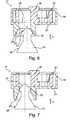
- the energy storage 13is roughly pre-positioned and brought to the support frame 11 to introduce the Einsteckbolzen 15 along the insertion direction E in the receiving units 17. If one of the plug-in bolts 15 and the associated receiving unit 17 are not exactly centered, the insertion bevel 31 of the plug-in bolt 15 passes as in FIG Fig. 6 shown in contact with the conical abutment surface 29 of the cage 19 and causes a corrective orientation of the energy storage 13 relative to the support frame 11, so that the Einsteckbolzen 15 can be passed through the insertion opening 23 of the cage 19. According to Fig.
- the Einsteckbolzen 15is further moved in the insertion direction E until the centering surface 35 of the Einsteckbolzens 15 abuts against the stop surface 29 of the cage 19.
- the conical surfaces 29, 35are in this state over the entire surface to each other.
- the locking element 21is rotated on the actuating portion 27 about the rotation axis R, whereby the width of the passage opening 25 is reduced at the location of the Einsteckbolzens 15 and the retaining projection 33 of the Einsteckbolzens 15 is thus engaged behind by the blocking surface 37. Due to the inclination of the blocking surface 37, the centering surface 35 of the Einsteckbolzens 15 is biased against the stop surface 29 of the cage 19.
- the passage opening 25 with the blocking surface 37can be designed such that there is a self-locking effect.
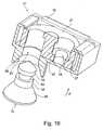
- a fastening deviceaccording to an alternative embodiment of the invention is shown, in which the retaining projection 33 of the Einsteckbolzens 15 is formed by a provided in the cylindrical portion 34 groove 50. That is, the holding projection 33 is not opposite the cylindrical portion 34 here.
- the fastening deviceworks like the in Fig. 4 to 9 illustrated arrangement, wherein for locking the blocking surface 37 engages in the groove 50.
- the receiving unit 17comprises an additional securing device 39 in the form of a latching lever 41 mounted pivotably on the cage 19, at one end of which a latching projection 43 is provided, which engages in one of two recesses 45 provided on the latching element 21.
- the two recesses 45 of the locking element 21are arranged such that the locking element 21 either in the release position or in the blocking position by means of the locking lever 41 with the cage 19 can be locked.
- the locking projection 43By pressing on the locking projection 43 opposite end of the locking lever 41, the locking projection 43 can be moved out of the respective recess 45 and the latching thus be solved.
- the locking lever 41is biased in the detent position.
- FIG. 13 and 14Different variants of fastening devices according to the invention are shown.
- Fig. 13shows the respective pins 15 and receiving units 17 in a separate state
- Fig. 14the plug pins 15 in conjunction with the associated receiving units 17 show.
- the embodiment according to the left part of Fig. 13 and 14corresponds to the above in connection with the Fig. 1 to 12 explained embodiments in which both the centering surface 35 of the retaining bolt 15 and the stop surface 29 of the cage 19 are tapered. With this locking variant, an exact centering in all spatial directions is accomplished. According to the middle part of Fig.
- the centering surface 35 of the pin 15is also conical, the stop surface 29 'of the cage 19, however, has two flat inclined surfaces, which are inclined relative to each other.
- the Einsteckbolzen 15can be moved by a certain amount even after a stop on the stop surface 29 'in a direction perpendicular to the plug E, ie there is a degree of freedom of movement to compensate for tolerances.
- the insertion opening 23 'of the cage 19is formed as a slot.
- neither the Einsteckbolzen 15 nor the receiving unit 17 centering inclined surfaces and the insertion 23is compared to the embodiments according to Fig. 1 to 12 enlarged so that the pin 15 after the full insertion up to a flat stop 49 in a plane perpendicular to the insertion direction E can be moved on all sides.
- a fully centering fastening deviceaccording to the left part of Fig. 13 and 14 be provided while 13 only partially centering fastening devices are provided at the other three corner regions of the energy storage.
- a fastening device with conical inclined surfacesis provided at a corner region and fastening devices are provided with flat inclined surfaces at two other corner regions, wherein the flat inclined surfaces are aligned perpendicular to each other, so that a Zentri mecanics Anlagenkeit results in mutually independent directions.
- the inventionallows a detachable fastening of an electrical energy storage device to a motor vehicle, wherein a change of the energy storage can be performed quickly and easily and can be repeated as often as desired without excessive signs of wear.
Landscapes
- Engineering & Computer Science (AREA)
- Chemical & Material Sciences (AREA)
- General Chemical & Material Sciences (AREA)
- Electrochemistry (AREA)
- Chemical Kinetics & Catalysis (AREA)
- Mechanical Engineering (AREA)
- Transportation (AREA)
- Combustion & Propulsion (AREA)
- Life Sciences & Earth Sciences (AREA)
- Power Engineering (AREA)
- Sustainable Energy (AREA)
- Sustainable Development (AREA)
- Aviation & Aerospace Engineering (AREA)
- Arrangement Or Mounting Of Propulsion Units For Vehicles (AREA)
- Battery Mounting, Suspending (AREA)
Description
Translated fromGermanDie vorliegende Erfindung betrifft eine Befestigungsvorrichtung zum lösbaren Befestigen eines elektrischen Energiespeichers an einer Tragstruktur eines Kraftfahrzeugs, insbesondere eines Elektrofahrzeugs oder Hybridfahrzeugs.The present invention relates to a fastening device for releasably securing an electrical energy store to a support structure of a motor vehicle, in particular of an electric vehicle or hybrid vehicle.
Elektrofahrzeuge oder Hybridfahrzeuge weisen einen elektrischen Antriebsmotor auf, der ein Drehmoment auf die Fahrzeugräder überträgt. Die Energie zum Betrieb des elektrischen Antriebsmotors wird dem Energiespeicher entnommen, bei welchem es sich insbesondere um eine wiederaufladbare Batterie, d.h. einen Akkumulator handeln kann. Üblicherweise umfasst eine derartige Batterie eine Anordnung von galvanischen Zellen, welche in einem Gehäuse untergebracht sind. Die Batterie kann beispielsweise am Tragrahmen des Kraftfahrzeugs angeschraubt sein.Electric vehicles or hybrid vehicles have an electric drive motor that transmits torque to the vehicle wheels. The energy for operating the electric drive motor is taken from the energy store, which is in particular a rechargeable battery, i. can act an accumulator. Typically, such a battery includes an array of galvanic cells housed in a housing. The battery may for example be screwed to the support frame of the motor vehicle.
Wenn an dem Fahrzeug ein Batteriewechsel vorzunehmen ist, muss die Verschraubung zwischen der Batterie und dem Fahrzeug gelöst und nach Entnahme der bisherigen Batterie eine Ersatzbatterie angeschraubt werden. Aufgrund des Gewindeverschleißes kann sich die Zuverlässigkeit der Schraubverbindung insbesondere bei häufigen Auswechselvorgängen verschlechtern. Weiterhin erfordert eine Verschraubung mit sicherheitskritischem Charakter einen relativ hohen Montageaufwand, z.B. in Form einer besonders ausführlichen Dokumentation.If a battery change is to be made to the vehicle, the screw connection between the battery and the vehicle must be solved and screwed after removing the previous battery, a spare battery. Due to the thread wear, the reliability of the screw can deteriorate, especially with frequent replacement operations. Furthermore, a gland with safety-critical character requires a relatively high assembly cost, for example in the form of a particularly detailed documentation.
Aus der
Es ist eine Aufgabe der Erfindung, das lösbare Befestigen eines Energiespeichers am Tragrahmen eines Kraftfahrzeugs einfacherer und sicherer zu gestalten.It is an object of the invention to make releasably securing an energy storage to the support frame of a motor vehicle simpler and safer.
Die Aufgabe wird durch eine Befestigungsvorrichtung mit den Merkmalen des Anspruchs 1 gelöst.The object is achieved by a fastening device with the features of claim 1.
Erfindungsgemäß umfasst eine Befestigungsvorrichtung wenigstens einen Einsteckbolzen und eine Aufnahmeeinheit für den Einsteckbolzen, die an der Tragstruktur und an dem Energiespeicher vorgesehen sind oder umgekehrt, wobei der Einsteckbolzen einen Haltevorsprung umfasst, wobei die Aufnahmeeinheit einen Käfig und ein in dem Käfig gelagertes Verriegelungselement umfasst, wobei der Käfig eine Einstecköffnung umfasst, in die der Einsteckbolzen entlang einer Einsteckrichtung einführbar ist, und wobei das Verriegelungselement zwischen einer Freigabestellung und einer Sperrstellung beweglich ist, wobei das Verriegelungselement in der Freigabestellung die Einstecköffnung für ein Einführen des Einsteckbolzens freigibt und in der Sperrstellung, wenn der Einsteckbolzen in die Einstecköffnung des Käfigs eingeführt ist, den Haltevorsprung des Einsteckbolzens hintergreift, wobei das Verriegelungselement eine Blockierfläche umfasst, die den Haltevorsprung des Einsteckbolzens hintergreift, wenn der Einsteckbolzen in die Einstecköffnung des Käfigs eingeführt ist und das Verriegelungselement in die Sperrstellung bewegt ist, wobei die Blockierfläche des Verriegelungselements bezüglich einer Normalebene zu der Einsteckrichtung zumindest abschnittsweise geneigt ist.According to the invention, a fastening device comprises at least one insertion bolt and a receiving unit for the Einsteckbolzen, which are provided on the support structure and the energy storage or vice versa, wherein the Einsteckbolzen comprises a holding projection, wherein the receiving unit comprises a cage and a locking element mounted in the cage, wherein the Cage comprises an insertion opening into which the plug-in pin along a plug-in direction is inserted, and wherein the locking element is movable between a release position and a locking position, wherein the locking element releases the insertion opening for insertion of the plug in the release position and in the locked position when the plug pin is inserted into the insertion opening of the cage, engages behind the retaining projection of the Einsteckbolzens, wherein the locking element comprises a blocking surface, which behind the retaining projection of the Einsteckbolzens ft, when the pin is inserted into the insertion of the cage and the locking element is moved to the blocking position, wherein the blocking surface of the locking element is at least partially inclined with respect to a normal plane to the insertion direction.
Der Einsteckbolzen kann als separates Bauteil an der Tragstruktur befestigt oder direkt an dieser angeformt sein. Die Aufnahmeeinheit ist vorzugsweise an einem Gehäuse des Energiespeichers befestigt. Ebenso ist es möglich, dass die Aufnahmeeinheit an der Tragstruktur befestigt ist und der Einsteckbolzen an einem Gehäuse des Energiespeichers befestigt oder angeformt ist. Wenn sich das Verriegelungselement in der Freigabestellung befindet, kann der Energiespeicher an das Fahrzeug herangeführt und unter Einführen des Einsteckbolzens in die Einstecköffnung des Käfigs in der korrekten Position an der Tragstruktur angeordnet werden. Durch anschließendes Bewegen des Verriegelungselements in die Sperrstellung wird eine zuverlässige formschlüssige Verbindung aufgrund des Hintergreifens des Haltevorsprungs des Einsteckbolzens hergestellt. Zum Auswechseln des Energiespeichers muss das Verriegelungselement lediglich in die Freigabestellung bewegt werden, so dass der Einsteckbolzen wieder aus der Aufnahmeeinheit herausgeführt werden kann.The pin may be attached as a separate component to the support structure or formed directly on this. The receiving unit is preferably attached to a housing of the energy store. It is also possible that the receiving unit is attached to the support structure and the plug-in bolt is attached or integrally formed on a housing of the energy store. When the locking element is in the release position, the energy storage device can be brought to the vehicle and arranged by inserting the insertion pin into the insertion opening of the cage in the correct position on the support structure. By subsequently moving the locking element in the blocking position, a reliable positive connection is produced due to the gripping behind of the holding projection of the plug-in pin. To replace the energy storage device, the locking element only has to be moved into the release position, so that the insertion bolt can be led out of the receiving unit again.
Zum Befestigen eines Energiespeichers am Fahrzeug sind somit nur ein Einsteckvorgang und eine Bewegung eines Verriegelungselements erforderlich, so dass sich eine einfache und schnelle Montage ergibt. Insbesondere kann ein Batteriewechsel auch durch ungeübtes Personal durchgeführt werden. Aufgrund des formschlüssigen Eingriffs zwischen dem Einsteckbolzen und der Aufnahmeeinheit ist dennoch ein hohes Maß an Sicherheit gewährleistet. Ein Gewindeverschleiß tritt nicht auf, so dass auch ein häufigeres Auswechseln des Energiespeichers problemlos möglich ist.To attach an energy storage device to the vehicle thus only a plugging operation and a movement of a locking element are required, so that there is a simple and quick installation. In particular, a battery change can also be carried out by untrained personnel. Due to the positive engagement between the pin and the receiving unit a high level of security is still guaranteed. A thread wear does not occur, so that a more frequent replacement of the energy storage is easily possible.
Bei der Blockierfläche kann es sich beispielsweise um die Umrandung einer Durchtrittsöffnung handeln. Die Neigung sorgt dafür, dass der Einsteckbolzen beim Bewegen des Verriegelungselements von der Freigabestellung in die Sperrstellung beispielsweise gegen eine Anschlagfläche der Aufnahmeeinheit gespannt wird, vorzugsweise in einer selbsthemmenden Weise. Eine Betätigung des Verriegelungselements bewirkt somit nicht nur eine Verriegelung des Energiespeichers an der Tragstruktur, sondern auch eine Sicherung gegen unerwünschtes Wackeln.The blocking surface may be, for example, the border of a passage opening. The inclination ensures that when the locking element is moved from the release position into the blocking position, the locking pin is tensioned, for example, against a stop surface of the receiving unit, preferably in a self-locking manner. An actuation of the locking element thus not only causes a locking of the energy storage device on the support structure, but also a backup against unwanted shaking.
Weiterbildungen der Erfindung sind in den abhängigen Ansprüchen, der Beschreibung sowie den beigefügten Zeichnungen angegeben.Further developments of the invention are specified in the dependent claims, the description and the accompanying drawings.
Gemäß einer Ausführungsform der Erfindung umfasst der Einsteckbolzen wenigstens eine Zentrierfläche, die schräg zu der Einführrichtung des Einsteckbolzens ausgerichtet ist, wobei der Käfig der Aufnahmeeinheit wenigstens eine Anschlagfläche umfasst, die schräg zu der Einführrichtung des Einsteckbolzens ausgerichtet ist, wobei die Zentrierfläche des Einsteckbolzens und die Anschlagfläche des Käfigs beim Einführen des Einsteckbolzens in die Einstecköffnung derart zusammenwirken, dass der Einsteckbolzen und der Käfig in wenigstens einer Richtung senkrecht zu der Einsteckrichtung relativ zueinander zentriert werden. Die Zentrierfläche und die Anschlagfläche dienen somit als Zentrierhilfe. Insbesondere muss vor dem Einführen des Einsteckbolzens keine aufwendige exakte Positionierung des Energiespeichers relativ zu der Tragstruktur erfolgen.According to one embodiment of the invention, the pin has at least one centering surface, which is aligned obliquely to the insertion direction of the pin, wherein the cage of the receiving unit comprises at least one stop surface, which is aligned obliquely to the insertion direction of the pin, wherein the centering surface of the pin and the stop surface the cage during insertion of the male pin in the insertion cooperate such that the pin and the cage are centered in at least one direction perpendicular to the insertion relative to each other. The centering surface and the stop surface thus serve as centering. In particular, no expensive exact positioning of the energy store relative to the support structure must be carried out prior to insertion of the push-in pin.
Gemäß einer Ausgestaltung der Erfindung ist die Zentrierfläche des Einsteckbolzens kegelförmig. Der Einsteckbolzen kann somit in unterschiedlichen Richtungen zentriert werden.According to one embodiment of the invention, the centering surface of the push-in pin is conical. The plug-in pin can thus be centered in different directions.
Die Anschlagfläche des Käfigs kann kegelförmig oder eben sein oder der Käfig kann zwei ebene Anschlagflächen umfassen, die relativ zueinander geneigt sind. Insbesondere kann die Zentrierfläche des Einsteckbolzens kegelförmig sein und die Anschlagfläche des Käfigs kann ebenfalls kegelförmig sein. In diesem Fall ist eine Zentrierung in beliebiger Richtung senkrecht zu der Einführrichtung möglich. Vorzugsweise sind bei einer derartigen Ausgestaltung die Kegelflächen gleichartig geformt, so dass sich nach dem Einführen des Einsteckbolzens in die Aufnahmeeinheit ein flächiger Anschlag mit hoher Festigkeit ergibt. Bei einer Ausgestaltung mit zwei ebenen Anschlagflächen besteht in einer Richtung ein Bewegungsfreiheitsgrad zwischen dem Einsteckbolzen und der Aufnahmeeinheit, welcher zum Ausgleichen von Toleranzen hilfreich ist.The abutment surface of the cage may be conical or flat or the cage may comprise two planar abutment surfaces which are inclined relative to one another. In particular, the centering surface of the male pin may be tapered and the stop surface of the cage may also be tapered. In this case, a centering in any direction perpendicular to the insertion direction is possible. Preferably, in such an embodiment, the conical surfaces are shaped similar, so that after insertion of the pin into the receiving unit results in a flat stop with high strength. In an embodiment with two flat abutment surfaces there is a degree of freedom of movement between the plug-in bolt and the receiving unit in one direction, which is helpful for compensating for tolerances.
An der Zentrierfläche des Einsteckbolzens oder an der Anschlagfläche des Käfigs kann ein elastisch verformbares Dämpfungselement vorgesehen sein. Ein derartiges Dämpfungselement kann unerwünschte Geräusche und Schwingungen verringern oder vermeiden.An elastically deformable damping element can be provided on the centering surface of the plug-in pin or on the stop surface of the cage. Such a damping element can reduce or avoid unwanted noise and vibrations.
Die Einstecköffnung des Käfigs kann ein Langloch sein. Ein Langloch als Einstecköffnung ist insbesondere dann sinnvoll, wenn an dem Käfig zwei ebene, relativ zueinander geneigte Anschlagflächen vorgesehen sind, wobei die Längsrichtung des Langlochs parallel zu den zwei ebenen Anschlagflächen verläuft. Der Bewegungsfreiheitsgrad bleibt dann erhalten, da sich der Einsteckbolzen in dem Langloch in der entsprechenden Längsrichtung des Langlochs bewegen kann.The insertion of the cage can be a slot. An oblong hole as an insertion opening is particularly useful when two flat, relatively inclined stop surfaces are provided on the cage, wherein the longitudinal direction of the slot parallel to the two flat abutment surfaces. The degree of freedom of movement is then maintained because the pin can move in the slot in the corresponding longitudinal direction of the slot.
Das Verriegelungselement definiert vorzugsweise eine Durchtrittsöffnung mit variabler Breite. Durch Bewegen des Verriegelungselements in dem Käfig kann die Breite der Durchtrittsöffnung verringert werden, wodurch sich eine Umrandung der Durchtrittsöffnung immer mehr dem Bolzen nähert und schließlich dessen Haltevorsprung hintergreift. D.h. die Umrandung der Durchtrittsöffnung definiert eine Blockierfläche, welche beim Bewegen des Verriegelungselements in einen formschlüssigen Eingriff mit dem Haltevorsprung gerät.The locking element preferably defines a passage opening with a variable width. By moving the locking element in the cage, the width of the passage opening can be reduced, whereby a border of the passage opening more and more the bolt approaches and finally engages behind its retaining projection. That is, the border of the passage opening defines a blocking surface, which gets into a positive engagement with the holding projection when moving the locking element.
Das Verriegelungselement kann zwischen der Freigabestellung und der Sperrstellung um eine Rotationsachse verdrehbar sein. Es ergibt sich dadurch ein besonders einfaches Betätigen des Verriegelungselements zum Befestigen oder Lösen der Verbindung. Gemäß einer Ausgestaltung der Erfindung bildet die Blockierfläche des Verriegelungselements eine Kurvenbahn, insbesondere zwei abschnittsweise konzentrische Kurvenbahnen. Alternativ kann das Verriegelungselement auch geradlinig versetzbar sein.The locking element may be rotatable about an axis of rotation between the release position and the blocking position. This results in a particularly simple operation of the locking element for attaching or releasing the connection. According to one embodiment of the invention, the blocking surface of the locking element forms a curved path, in particular two sections concentric curved paths. Alternatively, the locking element can also be rectilinearly offset.
Gemäß einer weiteren Ausführungsform der Erfindung ist das Verriegelungselement derart mit Spiel in dem Käfig gelagert, dass das Verriegelungselement in einer quer zu der Einsteckrichtung des Einsteckbolzens verlaufenden Ebene relativ zu dem Käfig zweidimensional beweglich ist. Eine derartige Lagerung kann zur Kompensation von Toleranzen herangezogen werden. Die vorstehend genannte Rotationsachse eines verdrehbaren Verriegelungselements wird hierdurch ebenfalls zweidimensional versetzt.According to a further embodiment of the invention, the locking element is mounted with play in the cage in such a way that the locking element is two-dimensionally movable relative to the cage in a plane extending transversely to the insertion direction of the push-in pin. Such storage can be used to compensate for tolerances. The above-mentioned rotation axis of a rotatable locking element is thereby also offset two-dimensionally.
Die Aufnahmeeinheit kann eine Sicherungseinrichtung umfassen, mittels derer das Verriegelungselement in der Freigabestellung und/oder in der Sperrstellung sicherbar ist, insbesondere durch einen jeweiligen Rastschluss. Eine derartige Sicherungseinrichtung kann Schutz vor versehentlichem Lösen der Befestigungsvorrichtung bieten.The receiving unit may comprise a securing device, by means of which the locking element in the release position and / or in the locked position is securable, in particular by a respective latching. Such a security device can provide protection against accidental release of the fastening device.
Weiterhin kann das freie Ende des Einsteckbolzens eine, insbesondere kegelförmige, Einführschräge aufweisen. Eine derartige Einführschräge kann eine zusätzliche Montagehilfe sein. Insbesondere kann mittels der Einführschräge eine grobe Vorpositionierung vor dem eigentlichen Zentriervorgang mittels der Zentrierfläche und der Anschlagfläche durchgeführt werden.Furthermore, the free end of the Einsteckbolzens have a, in particular conical, insertion bevel. Such an insertion bevel can be an additional assembly aid. In particular, a rough pre-positioning can be carried out before the actual centering by means of the centering surface and the stop surface by means of the insertion bevel.
Die Erfindung betrifft ferner ein Befestigungssystem mit mehreren, vorzugsweise zwei, drei oder vier, Befestigungsvorrichtungen der erläutertenThe invention further relates to a fastening system with a plurality, preferably two, three or four, fastening devices of the explained
Art, wobei die Befestigungsvorrichtungen vorzugsweise für verschiedene Eckbereiche des Energiespeichers vorgesehen sind. Ein Energiespeicher kann somit allein durch die Befestigungsvorrichtungen sicher an einem Fahrzeug gehalten werden. Vorzugsweise wird der Energiespeicher von unten an dem Fahrzeug befestigt. Zu diesem Zweck kann ein Hohlraum zur Aufnahme des Energiespeichers an der Fahrzeugunterseite vorgesehen sein.Art, wherein the fastening devices are preferably provided for different corner regions of the energy storage. An energy storage device can thus be held securely on a vehicle solely by the fastening devices. The energy store is preferably fastened to the vehicle from below. For this purpose, a cavity for receiving the energy storage device may be provided on the vehicle underside.
Gemäß einer Ausführungsform eines derartigen Befestigungssystems umfasst der Käfig der Aufnahmeeinheit einer ersten der mehreren Befestigungsvorrichtungen eine kegelförmige Anschlagfläche, die mit einer kegelförmigen Zentrierfläche des Einsteckbolzens der ersten Befestigungsvorrichtung derart zusammenwirkt, dass der Einsteckbolzen und der Käfig in zwei zueinander senkrechten Richtungen innerhalb einer Normalebene zu der Einsteckrichtung relativ zueinander zentriert werden. Der Käfig der Aufnahmeeinheit einer zweiten der mehreren Befestigungsvorrichtungen umfasst wenigstens eine ebene Anschlagfläche, die schräg zu der Einführrichtung des Einsteckbolzens der zweiten Befestigungsvorrichtung ausgerichtet ist und die mit einer kegelförmigen Zentrierfläche oder wenigstens einer ebenen Zentrierfläche des Einsteckbolzens derart zusammenwirkt, dass der Einsteckbolzen und der Käfig in einer ersten Richtung senkrecht zu der Einsteckrichtung relativ zueinander zentriert werden. Die erste Befestigungsvorrichtung bewirkt also eine vollständige Zentrierung des Energiespeichers und der Tragstruktur in der Normalebene, wohingegen bei der zweiten Befestigungsvorrichtung ein Freiheitsgrad in einer Richtung quer zu der Einführrichtung besteht, welcher eine Kompensation von toleranzbedingten Fehlstellungen erlaubt.According to one embodiment of such a fastening system, the cage of the receiving unit of a first of the plurality of fastening devices comprises a conical abutment surface which cooperates with a conical centering surface of the pin of the first fastening device such that the pin and the cage in two mutually perpendicular directions within a normal plane to the insertion direction be centered relative to each other. The cage of the receiving unit of a second of the plurality of fastening devices comprises at least one planar stop surface, which is aligned obliquely to the insertion direction of the pin of the second fastening device and which cooperates with a conical centering surface or at least a planar centering surface of the pin so that the pin and the cage in a first direction perpendicular to the insertion direction are centered relative to each other. The first fastening device thus causes a complete centering of the energy storage and the supporting structure in the normal plane, whereas in the second fastening device there is a degree of freedom in a direction transverse to the insertion direction, which allows a compensation of tolerance-induced misalignments.
Gemäß einer Weiterbildung dieser Ausführungsform umfasst der Käfig der Aufnahmeeinheit einer dritten der mehreren Befestigungsvorrichtungen wenigstens eine ebene Anschlagfläche, die schräg zu der Einführrichtung des Einsteckbolzens der dritten Befestigungsvorrichtung ausgerichtet ist und die mit einer kegelförmigen Zentrierfläche oder wenigstens einer ebenen Zentrierfläche des Einsteckbolzens derart zusammenwirkt, dass der Einsteckbolzen und der Käfig in einer zweiten Richtung senkrecht zu der Einsteckrichtung relativ zueinander zentriert werden, wobei die zweite Richtung senkrecht zu der ersten Richtung steht. Während der Energiespeicher bei dieser Ausführungsform wiederum an der ersten Befestigungsvorrichtung in allen Raumrichtungen festgehalten ist, bestehen bei der zweiten Befestigungsvorrichtung und bei der dritten Befestigungsvorrichtung jeweilige Freiheitsgrade, die einen Ausgleich von Toleranzen ermöglichen. Da die erste Richtung und die zweite Richtung senkrecht zueinander verlaufen, ist die Position des Energiespeichers jedoch nach dem Befestigen vollständig festgelegt.According to a development of this embodiment, the cage of the receiving unit comprises a third of the plurality of fastening devices at least one flat stop surface, which is aligned obliquely to the insertion direction of the Einsteckbolzens the third fastening device and which cooperates with a conical centering or at least a planar centering surface of the Einsteckbolzens such that the Einsteckbolzen and the cage in a second direction perpendicular to the insertion relative to each other centered be with the second direction is perpendicular to the first direction. While the energy store in this embodiment, in turn, is held on the first fastening device in all spatial directions, in the second fastening device and in the third fastening device, there are respective degrees of freedom which make it possible to compensate for tolerances. However, since the first direction and the second direction are perpendicular to each other, the position of the energy storage is completely fixed after fixing.
Wenigstens eine der mehreren Befestigungsvorrichtungen kann eine Aufnahmeeinheit für einen Einsteckbolzen aufweisen, an welcher keine schräg ausgerichtete Anschlagfläche für den Einsteckbolzen vorgesehen ist. Auf diese Weise kann eine Überbestimmtheit vermieden werden.At least one of the plurality of fastening devices can have a receiving unit for a plug-in bolt, on which no obliquely oriented stop surface is provided for the plug-in bolt. In this way, over-determination can be avoided.
Gemäß einer alternativen Ausführungsform des genannten Befestigungssystems ist der Käfig der Aufnahmeeinheit einer ersten der mehreren Befestigungsvorrichtungen ohne eine schräg ausgerichtete Anschlagfläche für den Einsteckbolzen ausgebildet und der Käfig der Aufnahmeeinheit einer zweiten der mehreren Befestigungsvorrichtungen umfasst wenigstens eine ebene Anschlagfläche, die schräg zu der Einführrichtung des Einsteckbolzens der zweiten Befestigungsvorrichtung ausgerichtet ist und die mit einer kegelförmigen Zentrierfläche oder wenigstens einer ebenen Zentrierfläche des Einsteckbolzens derart zusammenwirkt, dass der Einsteckbolzen und der Käfig in einer ersten Richtung senkrecht zu der Einsteckrichtung relativ zueinander zentriert werden. Diese Ausführungsform ermöglicht eine größere Toleranz hinsichtlich der Ausrichtung des Energiespeichers relativ zu der Tragstruktur.According to an alternative embodiment of the said fastening system, the cage of the receiving unit of a first of the plurality of fastening devices without an obliquely oriented abutment surface for the Einsteckbolzen and the cage of the receiving unit of a second of the plurality of fastening devices comprises at least one flat stop surface, which is oblique to the insertion direction of the Einsteckbolzens second fastening device is aligned and which cooperates with a conical centering surface or at least a planar centering surface of the male so that the male pin and the cage in a first direction perpendicular to the insertion direction be centered relative to each other. This embodiment allows a greater tolerance with respect to the orientation of the energy store relative to the support structure.
Weiterhin kann der Käfig der Aufnahmeeinheit einer dritten der mehreren Befestigungsvorrichtungen wenigstens eine ebene Anschlagfläche umfassen, die schräg zu der Einführrichtung des Einsteckbolzens der dritten Befestigungsvorrichtung ausgerichtet ist und die mit einer kegelförmigen Zentrierfläche oder wenigstens einer ebenen Zentrierfläche des Einsteckbolzens derart zusammenwirkt, dass der Einsteckbolzen und der Käfig in einer zweiten Richtung senkrecht zu der Einsteckrichtung relativ zueinander zentriert werden, wobei die zweite Richtung senkrecht zu der ersten Richtung steht. Die exakte Ausrichtung des Energiespeichers relativ zu der Tragstruktur wird bei dieser Ausführungsform also ausschließlich über die senkrecht zueinander ausgerichteten ebenen Schrägflächen der ersten und der zweiten Befestigungsvorrichtung erzielt.Furthermore, the cage of the receiving unit of a third of the plurality of fastening devices comprise at least one planar stop surface which is aligned obliquely to the insertion direction of the pin of the third fastening device and which cooperates with a conical centering surface or at least a planar centering surface of the pin such that the pin and the Cage are centered in a second direction perpendicular to the insertion direction relative to each other, wherein the second direction is perpendicular to the first direction. The exact alignment of the energy store relative to the support structure is thus achieved in this embodiment exclusively via the mutually perpendicular planar inclined surfaces of the first and the second fastening device.
Vorzugsweise sind zwei Aufnahmeeinheiten mit ebenen Anschlagflächen vorgesehen, die senkrecht zueinander wirksam sind.Preferably, two receiving units are provided with flat abutment surfaces which are perpendicular to each other.
Die Erfindung bezieht sich auch auf ein Energiespeichersystem für ein Kraftfahrzeug mit wenigstens einem elektrischen Energiespeicher und mit mehreren Befestigungsvorrichtungen der erläuterten Art, um den Energiespeicher lösbar an einer Tragstruktur des Kraftfahrzeugs zu befestigen.The invention also relates to an energy storage system for a motor vehicle with at least one electrical energy storage and with a plurality of fastening devices of the type described in order to detachably attach the energy store to a support structure of the motor vehicle.
Die Erfindung wird nachfolgend beispielhaft unter Bezugnahme auf die Zeichnungen beschrieben.
- Fig. 1
- zeigt ein Kraftfahrzeug mit einer Tragstruktur und einem mittels eines erfindungsgemäßen Befestigungssystems an der Tragstruktur zu befestigenden Energiespeicher.
- Fig. 2
- ist eine perspektivische Darstellung einer erfindungsgemäßen Befestigungsvorrichtung.
- Fig. 3
- ist eine Draufsicht auf die Befestigungsvorrichtung gemäß
Fig. 2 . - Fig. 4
- ist eine perspektivische, teilweise aufgeschnittene Darstellung der Befestigungsvorrichtung gemäß
Fig. 2 . - Fig. 5
- ist eine seitliche Schnittdarstellung der Befestigungsvorrichtung gemäß
Fig. 2 . - Fig. 6
- zeigt einen Einsteckbolzen der Befestigungsvorrichtung gemäß
Fig. 2 in einer ersten Phase des Einführens in eine zugehörige Aufnahmeeinheit. - Fig. 7
- zeigt den Einsteckbolzen gemäß
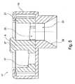
Fig. 6 in einer zweiten Phase des Einführens. - Fig. 8
- zeigt den Einsteckbolzen in einem voll eingeführten Zustand, wobei sich ein Verriegelungselement der Aufnahmeeinheit in einer Freigabestellung befindet.
- Fig. 9
- zeigt die Anordnung gemäß
Fig. 8 , wobei sich das Verriegelungselement in der Sperrstellung befindet. - Fig. 10
- ist eine perspektivische, teilweise aufgeschnittene Darstellung einer Befestigungsvorrichtung gemäß einer alternativen Ausgestaltung der Erfindung.
- Fig. 11
- zeigt eine Draufsicht auf eine erfindungsgemäße Befestigungsvorrichtung, welche eine Sicherungseinrichtung umfasst.
- Fig. 12
- zeigt eine Rückansicht der Befestigungsvorrichtung gemäß
Fig. 11 . - Fig. 13
- zeigt verschiedene Ausführungsformen von erfindungsgemäßen Befestigungsvorrichtungen, welche sich hinsichtlich der Form einer Anschlagfläche der Aufnahmeeinheit und/oder einer Form einer Zentrierfläche des Einsteckbolzens unterscheiden.
- Fig. 14
- zeigt die Befestigungsvorrichtungen gemäß
Fig. 13 in einem verriegelten Zustand.
- Fig. 1
- shows a motor vehicle with a support structure and by means of a fastening system according to the invention to be attached to the support structure energy storage.
- Fig. 2
- is a perspective view of a fastening device according to the invention.
- Fig. 3
- is a plan view of the fastening device according to
Fig. 2 , - Fig. 4
- is a perspective, partially cutaway view of the fastening device according to
Fig. 2 , - Fig. 5
- is a side sectional view of the fastening device according to
Fig. 2 , - Fig. 6
- shows a Einsteckbolzen the fastening device according to
Fig. 2 in a first phase of insertion into an associated receiving unit. - Fig. 7
- shows the plug in accordance with
Fig. 6 in a second phase of introduction. - Fig. 8
- shows the Einsteckbolzen in a fully inserted state, wherein a locking element of the receiving unit is in a release position.
- Fig. 9
- shows the arrangement according to
Fig. 8 , wherein the locking element is in the locked position. - Fig. 10
- is a perspective, partially cutaway view of a fastening device according to an alternative embodiment of the invention.
- Fig. 11
- shows a plan view of a fastening device according to the invention, which comprises a securing device.
- Fig. 12
- shows a rear view of the fastening device according to
Fig. 11 , - Fig. 13
- shows various embodiments of fastening devices according to the invention, which differ with regard to the shape of a stop surface of the receiving unit and / or a shape of a centering surface of the plug-in pin.
- Fig. 14
- shows the fastening devices according to
Fig. 13 in a locked state.
Die Befestigungsvorrichtungen sind mit einem Mechanismus zum lösbaren Verriegeln des Energiespeichers 13 am Tragrahmen 11 ausgestattet, wie nachfolgend unter Bezugnahme auf die
Der Einsteckbolzen 15 weist an seinem freien Ende eine kegelförmige Einführschräge 31 auf, welche in einen Haltevorsprung 33 übergeht. Im Anschluss an einen der Einführschräge 31 und dem Haltevorsprung 33 entgegen der Einsteckrichtung E nachfolgenden zylindrischen Abschnitt 34 ist eine kegelförmige Zentrierfläche 35 vorgesehen, deren Form mit der kegelförmigen Anschlagfläche 29 des Käfigs 19 übereinstimmt.The plug-in
Wie aus
Durch Drehen des Betätigungsabschnitts 27 kann das Verriegelungselement 21 zwischen einer in
Der Befestigungsvorgang wird nachfolgend unter Bezugnahme auf die
In
Gemäß einer in
In den
Durch eine Kombination der in den
Insgesamt ermöglicht die Erfindung ein lösbares Befestigen eines elektrischen Energiespeichers an einem Kraftfahrzeug, wobei ein Wechsel des Energiespeichers schnell und einfach durchgeführt und ohne übermäßige Verschleißerscheinungen beliebig häufig wiederholt werden kann.Overall, the invention allows a detachable fastening of an electrical energy storage device to a motor vehicle, wherein a change of the energy storage can be performed quickly and easily and can be repeated as often as desired without excessive signs of wear.
- 1111
- Tragrahmensupporting frame
- 1212
- Gehäusecasing
- 1313
- Energiespeicherenergy storage
- 1414
- umlaufender Vorsprungcircumferential lead
- 1515
- EinsteckbolzenBolts
- 1717
- Aufnahmeeinheitrecording unit
- 1919
- KäfigCage
- 2121
- Verriegelungselementlocking element
- 23, 23', 23"23, 23 ', 23 "
- Einstecköffnunginsertion
- 2525
- DurchtrittsöffnungThrough opening
- 2727
- Betätigungsabschnittactuating section
- 29, 29'29, 29 '
- Anschlagflächestop surface
- 3131
- Einführschrägechamfer
- 3333
- Haltevorsprungretaining projection
- 3434
- zylindrischer Abschnittcylindrical section
- 3535
- Zentrierflächecentering
- 3737
- Blockierflächeblocking surface
- 3939
- Sicherungseinrichtungsafety device
- 4141
- Rasthebellocking lever
- 4343
- Rastvorsprungcatch projection
- 4545
- Aussparungrecess
- 4747
- Federfeather
- 4949
- ebener Anschlageven stop
- 5050
- Nutgroove
- Ee
- Einsteckrichtunginsertion
- RR
- Rotationsachseaxis of rotation
Claims (17)
- Fastening apparatus for releasably fastening an electric energy store (13) to a supporting structure (11) of a motor vehicle, in particular a hybrid vehicle or electric vehicle, having at least one plug-in pin (15) and a receiving unit (17) for the plug-in pin (15), which are provided on the supporting structure (11) and on the energy store (13) or vice versa, the plug-in pin (15) comprising a holding projection (33), the receiving unit (17) comprising a cage (19) and a locking element (21) which is mounted in the cage (19), the cage (19) comprising an plug-in opening (23, 23', 23"), into which the plug-in pin (15) can be introduced along an plug-in direction (E), and the locking element (21) being movable between a released position and a blocked position, the locking element (21) releasing, in the released position, the plug-in opening (23, 23', 23") for introduction of the plug-in pin (15) and, in the blocked position, engaging behind the holding projection (33) of the plug-in pin (15) when the plug-in pin (15) is introduced into the plug-in opening (23, 23', 23") of the cage (19),characterized in that the locking element (21) comprises a blocking face (37) which engages behind the holding projection (33) of the plug-in pin (15) when the plug-in pin (15) is introduced into the plug-in opening (23, 23', 23") of the cage (19) and the locking element (21) is moved into the blocked position, the blocking face (37) of the locking element (21) being inclined at least in sections with regard to a normal plane with respect to the plug-in direction (E).
- Fastening apparatus according to Claim 1, the plug-in pin (15) comprising at least one centring face (35) which is oriented obliquely with respect to the introduction direction (E) of the plug-in pin (15), the cage (19) of the receiving unit (17) comprising at least one stop face (29, 29') which is oriented obliquely with respect to the introduction direction (E) of the plug-in pin (15), the centring face (35) of the plug-in pin (15) and the stop face (29, 29') of the cage (19) interacting during the introduction of the plug-in pin (15) into the plug-in opening (23, 23') in such a way that the plug-in pin (15) and the cage (19) are centred relative to one another in at least one direction perpendicularly with respect to the plug-in direction (E).
- Fastening apparatus according to Claim 2, the centring face (35) of the plug-in pin (15) being conical.
- Fastening apparatus according to Claim 2 or 3, an elastically deformable damping element being provided on the centring face (35) of the plug-in pin (15) or on the stop face (29, 29') of the cage (19).
- Fastening apparatus according to at least one of Claims 2 to 4, the stop face (29, 29') of the cage (19) being conical or planar.
- Fastening apparatus according to at least one of Claims 2 to 4, the cage (19) comprising two planar stop faces (29') which are inclined relative to one another, the plug-in opening (23') of the cage (19) preferably being a slot which extends parallel to the two planar stop faces (29').
- Fastening apparatus according to at least one of the preceding claims, the locking element (21) defining a passage opening (25) with a variable width.
- Fastening apparatus according to at least one of the preceding claims, it being possible for the locking element (21) to be rotated about a rotational axis (R) between the released position and the blocked position.
- Fastening apparatus according to at least one of the preceding claims, the locking element (21) being mounted in the cage (19) with play in such a way that the locking element (21) can be moved in two dimensions relative to the cage (19) in a plane which runs transversely with respect to the plug-in direction (E) of the plug-in pin (15).
- Fastening apparatus according to at least one of the preceding claims, the receiving unit (17) comprising a securing device (39), by means of which the locking element (21) can be secured in the released position and/or in the blocked position, in particular by way of a respective latching connection.
- Fastening apparatus according to at least one of the preceding claims, the free end of the plug-in pin (15) having an introduction bevel (31) which is, in particular, conical.
- Fastening system having a plurality of, preferably two, three or four, fastening apparatuses in each case according to one of the preceding claims, the fastening apparatuses preferably being provided for different corner regions of the energy store (13).
- Fastening system according to Claim 12, the cage (19) of the receiving unit (17) of a first of the plurality of fastening apparatuses comprising a conical stop face (29) which interacts with a conical centring face (35) of the plug-in pin (15) of the first fastening apparatus in such a way that the plug-in pin (15) and the cage (19) are centred relative to one another in two mutually perpendicular directions within a normal plane with respect to the plug-in direction (E); and the cage (19) of the receiving unit (17) of a second of the plurality of fastening apparatuses comprising at least one planar stop face (29') which is oriented obliquely with respect to the introduction direction (E) of the plug-in pin (15) of the second fastening apparatus and which interacts with a conical centring face (35) or at least one planar centring face of the plug-in pin (15) in such a way that the plug-in pin (15) and the cage (19) are centred relative to one another in a first direction perpendicularly with respect to the plug-in direction (E).
- Fastening system according to Claim 13, the cage (19) of the receiving unit (17) of a third of the plurality of fastening apparatuses comprising at least one planar stop face (29') which is oriented obliquely with respect to the introduction direction (E) of the plug-in pin (15) of the third fastening apparatus and which interacts with a conical centring face (35) or at least one planar centring face of the plug-in pin (15) in such a way that the plug-in pin (15) and the cage (19) are centred relative to one another in a second direction perpendicularly with respect to the plug-in direction (E), the second direction lying perpendicularly with respect to the first direction.
- Fastening system according to at least one of Claims 12 to 14, at least one of the plurality of fastening apparatuses having a receiving unit (17) for a plug-in pin (15), on which no obliquely oriented stop face for the plug-in pin (15) is provided.
- Fastening system according to Claim 12, the cage (19) of the receiving unit (17) of a first of the plurality of fastening apparatuses being configured without an obliquely oriented stop face for the plug-in pin (15); and the cage (19) of the receiving unit (17) of a second of the plurality of fastening apparatuses comprising at least one planar stop face (29') which is oriented obliquely with respect to the introduction direction (E) of the plug-in pin (15) of the second fastening apparatus and which interacts with a conical centring face (35) or at least one planar centring face of the plug-in pin (15) in such a way that the plug-in pin (15) and the cage (19) are centred relative to one another in a first direction perpendicularly with respect to the plug-in direction (E).
- Fastening system according to Claim 16, the cage (19) of the receiving unit (17) of a third of the plurality of fastening apparatuses comprising at least one planar stop face (29') which is oriented obliquely with respect to the introduction direction (E) of the plug-in pin (15) of the third fastening apparatus and which interacts with a conical centring face (35) or at least one planar centring face of the plug-in pin (15) in such a way that the plug-in pin (15) and the cage (19) are centred relative to one another in a second direction perpendicularly with respect to the plug-in direction (E), the second direction lying perpendicularly with respect to the first direction.
Applications Claiming Priority (3)
| Application Number | Priority Date | Filing Date | Title |
|---|---|---|---|
| US32193610P | 2010-04-08 | 2010-04-08 | |
| US32228910P | 2010-04-09 | 2010-04-09 | |
| PCT/EP2011/055546WO2011124701A2 (en) | 2010-04-08 | 2011-04-08 | Fastening device |
Publications (2)
| Publication Number | Publication Date |
|---|---|
| EP2555934A2 EP2555934A2 (en) | 2013-02-13 |
| EP2555934B1true EP2555934B1 (en) | 2014-01-22 |
Family
ID=44454002
Family Applications (2)
| Application Number | Title | Priority Date | Filing Date |
|---|---|---|---|
| EP11713284.5AActiveEP2555934B1 (en) | 2010-04-08 | 2011-04-08 | Fastening device |
| EP11713283.7AActiveEP2555933B1 (en) | 2010-04-08 | 2011-04-08 | Fastening device |
Family Applications After (1)
| Application Number | Title | Priority Date | Filing Date |
|---|---|---|---|
| EP11713283.7AActiveEP2555933B1 (en) | 2010-04-08 | 2011-04-08 | Fastening device |
Country Status (4)
| Country | Link |
|---|---|
| US (2) | US8776926B2 (en) |
| EP (2) | EP2555934B1 (en) |
| CN (2) | CN102933412B (en) |
| WO (2) | WO2011124701A2 (en) |
Families Citing this family (45)
| Publication number | Priority date | Publication date | Assignee | Title |
|---|---|---|---|---|
| KR101313275B1 (en)* | 2011-12-16 | 2013-09-30 | 주식회사 모텍스 | Attach and detach device of battery for electric vehicle |
| JP6004774B2 (en)* | 2011-12-16 | 2016-10-12 | モテックス プロダクツ カンパニー リミテッド | Battery removal device for electric vehicles |
| US8813888B2 (en)* | 2012-02-06 | 2014-08-26 | Honda Motor Co., Ltd. | Vehicle body rear structure |
| JP5595442B2 (en)* | 2012-04-18 | 2014-09-24 | 本田技研工業株式会社 | Car power supply mounting structure |
| CN104284830B (en)* | 2012-05-08 | 2018-01-16 | Ksm铸造集团有限公司 | Modular axle assembly for a motor vehicle with electric drive |
| KR101428276B1 (en)* | 2012-12-12 | 2014-08-07 | 현대자동차주식회사 | Battery tray for vehicle |
| FR3015774A1 (en)* | 2013-12-24 | 2015-06-26 | Commissariat Energie Atomique | REMOVABLE FIXING SYSTEM FOR A BATTERY WITH A SUPPORT |
| CN104458281B (en)* | 2014-12-15 | 2017-07-18 | 上海新世纪机器人有限公司 | A kind of automatic the examination of road equipment of balanced car with two wheels |
| CN104576998B (en)* | 2015-01-14 | 2017-02-08 | 韩建方 | Conversion-type electric car battery compartment structure |
| CN105398319B (en)* | 2015-11-28 | 2017-11-17 | 邓刚 | Battery car and replacing battery methods |
| US9722223B1 (en)* | 2016-03-02 | 2017-08-01 | Ford Global Technologies, Llc | Battery pack retention assembly and method |
| EP3261149B1 (en)* | 2016-06-20 | 2021-09-15 | Magna Steyr Fahrzeugtechnik AG & Co KG | Mounting assembly |
| CN114148210B (en)* | 2016-11-21 | 2024-02-13 | 上海电巴新能源科技有限公司 | Locking devices and electric vehicles |
| DE102016123553A1 (en)* | 2016-12-06 | 2018-06-07 | Dr. Ing. H.C. F. Porsche Aktiengesellschaft | Vehicle body for an electrically driven vehicle |
| CN107585011B (en)* | 2017-09-07 | 2020-06-09 | 芜湖皖江知识产权运营中心有限公司 | New energy automobile battery mounting structure |
| EP3511184A1 (en)* | 2018-01-15 | 2019-07-17 | MAGNA STEYR Fahrzeugtechnik AG & Co KG | Motor vehicle with a support structure |
| US10668830B2 (en)* | 2018-02-28 | 2020-06-02 | Artisan Vehicle Systems Inc. | Method and system for mounting and dismounting batteries in a vehicle |
| US10906383B2 (en)* | 2018-02-28 | 2021-02-02 | Artisan Vehicle Systems, Inc. | Alignment and locking mechanism for removeable battery assembly |
| US10476059B1 (en) | 2018-05-07 | 2019-11-12 | Ford Global Technologies, Llc | Battery pack retention assembly and method |
| DE102018209104B4 (en)* | 2018-06-08 | 2021-04-01 | Audi Ag | Method for manufacturing a battery assembly |
| DE102018008465B4 (en)* | 2018-10-29 | 2025-01-09 | Volkswagen Aktiengesellschaft | Body structure for an electrically powered vehicle |
| JP7053522B2 (en)* | 2019-02-28 | 2022-04-12 | ファナック株式会社 | Robot fixing devices, robots and robot systems |
| CN109910583A (en)* | 2019-03-27 | 2019-06-21 | 上海玖行能源科技有限公司 | A battery pack slope locking mechanism |
| US11505084B2 (en)* | 2019-05-03 | 2022-11-22 | Oshkosh Corporation | Battery placement for electric refuse vehicle |
| US12337718B2 (en) | 2019-05-03 | 2025-06-24 | Oshkosh Corporation | Battery storage system for electric refuse vehicle |
| WO2021107827A1 (en)* | 2019-11-25 | 2021-06-03 | Husqvarna Ab | A hand-held electrically powered work tool |
| CN111106305B (en)* | 2019-11-29 | 2021-07-02 | 广东恒翼能科技有限公司 | Battery manufacturing method and system based on negative pressure assembly |
| CN111204254A (en)* | 2020-01-20 | 2020-05-29 | 浙江吉智新能源汽车科技有限公司 | A battery pack locking mechanism, a battery pack unlocking mechanism, a battery pack and a vehicle |
| DE112021000680T5 (en)* | 2020-01-23 | 2022-11-10 | Aulton New Energy Automotive Technology Group | Fastening system for a battery pack and method of assembling and disassembling a battery pack |
| US20220151354A1 (en)* | 2020-01-27 | 2022-05-19 | Kristopher Jon SODERSTROM | Electronic device cases with tracks for holding accessories and related methods |
| KR102726812B1 (en)* | 2020-03-11 | 2024-11-05 | 현대자동차주식회사 | Battery release system for vehicle |
| KR102726809B1 (en)* | 2020-03-11 | 2024-11-06 | 현대자동차주식회사 | Battery release system for vehicle |
| CN113400914A (en)* | 2020-03-17 | 2021-09-17 | 奥动新能源汽车科技有限公司 | Battery pack locking device, bracket assembly, electric vehicle and battery pack locking method |
| CN111703528B (en)* | 2020-05-28 | 2025-03-25 | 浙江欧凯车业有限公司 | A battery anti-theft structure for a shared electric scooter |
| CN111942213A (en)* | 2020-08-14 | 2020-11-17 | 欣旺达电子股份有限公司 | Locking device and power utilization device |
| DE102020122515A1 (en) | 2020-08-28 | 2022-03-03 | Bayerische Motoren Werke Aktiengesellschaft | Central connection of an energy storage structure in a vehicle floor |
| US11565769B2 (en) | 2020-12-11 | 2023-01-31 | Specialized Bicycle Components, Inc. | 3-position battery latching system |
| KR20220090789A (en)* | 2020-12-23 | 2022-06-30 | 현대자동차주식회사 | Battery mounting structure of electric vehicle |
| US11794812B2 (en)* | 2021-03-08 | 2023-10-24 | Ford Global Technologies, Llc | Vehicle frame for electric vehicle |
| DE102021202381A1 (en) | 2021-03-11 | 2022-09-15 | Volkswagen Aktiengesellschaft | Apparatus, method and system for securing a rechargeable electrical energy storage module |
| WO2023278602A1 (en)* | 2021-06-29 | 2023-01-05 | Oshkosh Corporation | Battery placement for electric refuse vehicle |
| CN113707992A (en)* | 2021-08-16 | 2021-11-26 | 宁波信泰机械有限公司 | Aluminum extrusion quick-change battery box structure and electric vehicle |
| CN115284851B (en)* | 2021-09-17 | 2024-07-02 | 奥动新能源汽车科技有限公司 | Locking device, bracket assembly, electric automobile, battery box locking method and unlocking method |
| DE102022206721A1 (en)* | 2022-06-30 | 2024-01-04 | Robert Bosch Gesellschaft mit beschränkter Haftung | Electrochemical energy storage system, vehicle, method for fixing and positioning a component and pair of wedge bodies |
| CN222673225U (en)* | 2024-02-08 | 2025-03-25 | 武汉蔚来能源有限公司 | Lock body assembly, power battery for vehicle, battery locking mechanism and vehicle |
Family Cites Families (20)
| Publication number | Priority date | Publication date | Assignee | Title |
|---|---|---|---|---|
| US1079709A (en)* | 1912-05-07 | 1913-11-25 | Gen Electric | Battery-support. |
| US1661779A (en)* | 1923-06-27 | 1928-03-06 | Commercial Truck Company | Battery cradle for electric trucks |
| GB1530132A (en)* | 1975-01-21 | 1978-10-25 | Lucas Industries Ltd | Electrically assisted cycle |
| FR2354897A1 (en)* | 1976-06-17 | 1978-01-13 | Peugeot | DEVICE FOR THE QUICK EXCHANGE OF AN ACCUMULATOR BATTERY ON AN ELECTRIC VEHICLE |
| JP3125198B2 (en)* | 1991-12-04 | 2001-01-15 | 本田技研工業株式会社 | Battery temperature control device for electric vehicle |
| DE4206360B4 (en)* | 1992-02-29 | 2008-04-03 | Audi Ag | Two-axle motor vehicle with a self-sufficient, exchangeable drive unit |
| US6085854A (en)* | 1994-12-13 | 2000-07-11 | Nissan Motor Co., Ltd. | Battery frame structure for electric motorcar |
| DE19529880A1 (en)* | 1995-08-14 | 1997-02-20 | Bayerische Motoren Werke Ag | High energy battery with several single cells |
| FR2798342B1 (en)* | 1999-09-14 | 2001-11-16 | Herve Vaysse | DEVICE FOR INTERCHANGEABILITY OF THE BATTERY OF AN ELECTRIC VEHICLE |
| JP2001088563A (en)* | 1999-09-28 | 2001-04-03 | Fuji Heavy Ind Ltd | Electric vehicle battery box mounting structure |
| US6483719B1 (en)* | 2000-03-21 | 2002-11-19 | Spraylat Corporation | Conforming shielded form for electronic component assemblies |
| JP3881317B2 (en)* | 2003-01-30 | 2007-02-14 | 川崎重工業株式会社 | Battery box for railway vehicles |
| GB2411389B (en)* | 2003-11-10 | 2006-07-05 | Lansing Linde Ltd | Battery replacement system for an industrial truck |
| FR2880476A3 (en)* | 2005-01-04 | 2006-07-07 | Joel Henry Marcel Enault | BATTERY BOX FOR ELECTRIC VEHICLE |
| JP5151363B2 (en)* | 2007-09-28 | 2013-02-27 | 三菱自動車工業株式会社 | Battery case for electric vehicles |
| CN201188435Y (en)* | 2008-01-18 | 2009-01-28 | 北京电巴科技有限公司 | Positioning device for automobile battery |
| FR2934927B1 (en)* | 2008-08-08 | 2011-06-03 | Renault Sas | BATTERY SUPPORT STRUCTURE FOR MOTOR VEHICLE |
| DE202008012144U1 (en)* | 2008-09-13 | 2008-12-04 | Jungheinrich Aktiengesellschaft | Device for securing a battery in a battery compartment of a truck |
| US8006793B2 (en)* | 2008-09-19 | 2011-08-30 | Better Place GmbH | Electric vehicle battery system |
| CN101618492B (en)* | 2009-07-24 | 2012-02-29 | 苏州宝馨科技实业股份有限公司 | Method for assembling upper support body of overhead cell support of hybrid vehicle and clamp thereof |
- 2011
- 2011-04-08CNCN201180028074.0Apatent/CN102933412B/enactiveActive
- 2011-04-08EPEP11713284.5Apatent/EP2555934B1/enactiveActive
- 2011-04-08CNCN201180017152.7Apatent/CN102858570B/enactiveActive
- 2011-04-08USUS13/639,517patent/US8776926B2/enactiveActive
- 2011-04-08WOPCT/EP2011/055546patent/WO2011124701A2/enactiveApplication Filing
- 2011-04-08USUS13/639,900patent/US8936124B2/enactiveActive
- 2011-04-08EPEP11713283.7Apatent/EP2555933B1/enactiveActive
- 2011-04-08WOPCT/EP2011/055544patent/WO2011124700A2/enactiveApplication Filing
Also Published As
| Publication number | Publication date |
|---|---|
| CN102933412A (en) | 2013-02-13 |
| EP2555933A2 (en) | 2013-02-13 |
| US8776926B2 (en) | 2014-07-15 |
| WO2011124700A2 (en) | 2011-10-13 |
| US20130020140A1 (en) | 2013-01-24 |
| CN102858570B (en) | 2016-03-23 |
| CN102858570A (en) | 2013-01-02 |
| EP2555933B1 (en) | 2014-01-22 |
| US8936124B2 (en) | 2015-01-20 |
| WO2011124701A2 (en) | 2011-10-13 |
| US20130037337A1 (en) | 2013-02-14 |
| WO2011124700A3 (en) | 2011-12-22 |
| WO2011124701A3 (en) | 2011-12-22 |
| EP2555934A2 (en) | 2013-02-13 |
| CN102933412B (en) | 2016-03-30 |
Similar Documents
| Publication | Publication Date | Title |
|---|---|---|
| EP2555934B1 (en) | Fastening device | |
| DE112007000086B4 (en) | Connection arrangement with a connection element | |
| EP2755838B1 (en) | Arrangement for securing an energy storage module on a module support | |
| DE102013004515B4 (en) | Device for detachably fastening an assembly part | |
| EP2098831A2 (en) | Sensor with holder | |
| WO2012038253A1 (en) | Mounting system | |
| WO2006089539A1 (en) | Heavy-duty mounting for connecting two components | |
| DE102016109499A1 (en) | System of a component and a fastening device | |
| WO2010046376A1 (en) | Attachment structure, attachment device and attachment system for attachment of a finishing component in an aircraft | |
| DE102021100676A1 (en) | Retaining element for attaching an attachment | |
| DE202015100360U1 (en) | Cable holder and cable holder system | |
| EP0982520B1 (en) | Device for connecting together hydraulic or pneumatic components, particularly solenoid valves | |
| EP2531379B1 (en) | Unit for fastening a component of a vehicle | |
| EP2405147B1 (en) | Fixing component | |
| WO2020182533A1 (en) | Holding device of a lighting module of a lighting unit, lighting module, and lighting unit of a vehicle | |
| DE102019130176A1 (en) | Connector part with a locking device | |
| DE102005005726B3 (en) | Control holder for fixing electronic control device in motor vehicle has insertion clip which is firmly connected to pocket of intake holder and two bolts are aligned with edge strips | |
| EP3281252B1 (en) | Honeycomb component | |
| DE102022110714A1 (en) | Fastening arrangement | |
| DE102021109669A1 (en) | Device for connecting panels | |
| DE102019008731A1 (en) | Screw arrangement | |
| EP3806248A1 (en) | Socket for electrically connecting a trailer to a motor vehicle | |
| WO2015193190A1 (en) | Lighting arrangement | |
| EP4047222B1 (en) | Connector for fixing a surface element to an undercut t-groove | |
| DE102019118816A1 (en) | Contact carrier for providing contact for cabling in a vehicle |
Legal Events
| Date | Code | Title | Description |
|---|---|---|---|
| PUAI | Public reference made under article 153(3) epc to a published international application that has entered the european phase | Free format text:ORIGINAL CODE: 0009012 | |
| 17P | Request for examination filed | Effective date:20120831 | |
| AK | Designated contracting states | Kind code of ref document:A2 Designated state(s):AL AT BE BG CH CY CZ DE DK EE ES FI FR GB GR HR HU IE IS IT LI LT LU LV MC MK MT NL NO PL PT RO RS SE SI SK SM TR | |
| DAX | Request for extension of the european patent (deleted) | ||
| GRAP | Despatch of communication of intention to grant a patent | Free format text:ORIGINAL CODE: EPIDOSNIGR1 | |
| INTG | Intention to grant announced | Effective date:20131030 | |
| GRAS | Grant fee paid | Free format text:ORIGINAL CODE: EPIDOSNIGR3 | |
| GRAA | (expected) grant | Free format text:ORIGINAL CODE: 0009210 | |
| AK | Designated contracting states | Kind code of ref document:B1 Designated state(s):AL AT BE BG CH CY CZ DE DK EE ES FI FR GB GR HR HU IE IS IT LI LT LU LV MC MK MT NL NO PL PT RO RS SE SI SK SM TR | |
| REG | Reference to a national code | Ref country code:GB Ref legal event code:FG4D Free format text:NOT ENGLISH | |
| REG | Reference to a national code | Ref country code:CH Ref legal event code:EP | |
| REG | Reference to a national code | Ref country code:AT Ref legal event code:REF Ref document number:650614 Country of ref document:AT Kind code of ref document:T Effective date:20140215 | |
| REG | Reference to a national code | Ref country code:IE Ref legal event code:FG4D Free format text:LANGUAGE OF EP DOCUMENT: GERMAN | |
| REG | Reference to a national code | Ref country code:DE Ref legal event code:R096 Ref document number:502011002105 Country of ref document:DE Effective date:20140227 | |
| REG | Reference to a national code | Ref country code:NL Ref legal event code:VDEP Effective date:20140122 | |
| REG | Reference to a national code | Ref country code:LT Ref legal event code:MG4D | |
| PG25 | Lapsed in a contracting state [announced via postgrant information from national office to epo] | Ref country code:LT Free format text:LAPSE BECAUSE OF FAILURE TO SUBMIT A TRANSLATION OF THE DESCRIPTION OR TO PAY THE FEE WITHIN THE PRESCRIBED TIME-LIMIT Effective date:20140122 Ref country code:NO Free format text:LAPSE BECAUSE OF FAILURE TO SUBMIT A TRANSLATION OF THE DESCRIPTION OR TO PAY THE FEE WITHIN THE PRESCRIBED TIME-LIMIT Effective date:20140422 Ref country code:IS Free format text:LAPSE BECAUSE OF FAILURE TO SUBMIT A TRANSLATION OF THE DESCRIPTION OR TO PAY THE FEE WITHIN THE PRESCRIBED TIME-LIMIT Effective date:20140522 | |
| PG25 | Lapsed in a contracting state [announced via postgrant information from national office to epo] | Ref country code:CY Free format text:LAPSE BECAUSE OF FAILURE TO SUBMIT A TRANSLATION OF THE DESCRIPTION OR TO PAY THE FEE WITHIN THE PRESCRIBED TIME-LIMIT Effective date:20140122 Ref country code:SE Free format text:LAPSE BECAUSE OF FAILURE TO SUBMIT A TRANSLATION OF THE DESCRIPTION OR TO PAY THE FEE WITHIN THE PRESCRIBED TIME-LIMIT Effective date:20140122 Ref country code:FI Free format text:LAPSE BECAUSE OF FAILURE TO SUBMIT A TRANSLATION OF THE DESCRIPTION OR TO PAY THE FEE WITHIN THE PRESCRIBED TIME-LIMIT Effective date:20140122 Ref country code:PT Free format text:LAPSE BECAUSE OF FAILURE TO SUBMIT A TRANSLATION OF THE DESCRIPTION OR TO PAY THE FEE WITHIN THE PRESCRIBED TIME-LIMIT Effective date:20140522 Ref country code:NL Free format text:LAPSE BECAUSE OF FAILURE TO SUBMIT A TRANSLATION OF THE DESCRIPTION OR TO PAY THE FEE WITHIN THE PRESCRIBED TIME-LIMIT Effective date:20140122 | |
| PG25 | Lapsed in a contracting state [announced via postgrant information from national office to epo] | Ref country code:RS Free format text:LAPSE BECAUSE OF FAILURE TO SUBMIT A TRANSLATION OF THE DESCRIPTION OR TO PAY THE FEE WITHIN THE PRESCRIBED TIME-LIMIT Effective date:20140122 Ref country code:HR Free format text:LAPSE BECAUSE OF FAILURE TO SUBMIT A TRANSLATION OF THE DESCRIPTION OR TO PAY THE FEE WITHIN THE PRESCRIBED TIME-LIMIT Effective date:20140122 Ref country code:LV Free format text:LAPSE BECAUSE OF FAILURE TO SUBMIT A TRANSLATION OF THE DESCRIPTION OR TO PAY THE FEE WITHIN THE PRESCRIBED TIME-LIMIT Effective date:20140122 | |
| REG | Reference to a national code | Ref country code:DE Ref legal event code:R097 Ref document number:502011002105 Country of ref document:DE | |
| PG25 | Lapsed in a contracting state [announced via postgrant information from national office to epo] | Ref country code:DK Free format text:LAPSE BECAUSE OF FAILURE TO SUBMIT A TRANSLATION OF THE DESCRIPTION OR TO PAY THE FEE WITHIN THE PRESCRIBED TIME-LIMIT Effective date:20140122 Ref country code:CZ Free format text:LAPSE BECAUSE OF FAILURE TO SUBMIT A TRANSLATION OF THE DESCRIPTION OR TO PAY THE FEE WITHIN THE PRESCRIBED TIME-LIMIT Effective date:20140122 Ref country code:EE Free format text:LAPSE BECAUSE OF FAILURE TO SUBMIT A TRANSLATION OF THE DESCRIPTION OR TO PAY THE FEE WITHIN THE PRESCRIBED TIME-LIMIT Effective date:20140122 Ref country code:RO Free format text:LAPSE BECAUSE OF FAILURE TO SUBMIT A TRANSLATION OF THE DESCRIPTION OR TO PAY THE FEE WITHIN THE PRESCRIBED TIME-LIMIT Effective date:20140122 | |
| PG25 | Lapsed in a contracting state [announced via postgrant information from national office to epo] | Ref country code:SK Free format text:LAPSE BECAUSE OF FAILURE TO SUBMIT A TRANSLATION OF THE DESCRIPTION OR TO PAY THE FEE WITHIN THE PRESCRIBED TIME-LIMIT Effective date:20140122 Ref country code:LU Free format text:LAPSE BECAUSE OF FAILURE TO SUBMIT A TRANSLATION OF THE DESCRIPTION OR TO PAY THE FEE WITHIN THE PRESCRIBED TIME-LIMIT Effective date:20140408 Ref country code:PL Free format text:LAPSE BECAUSE OF FAILURE TO SUBMIT A TRANSLATION OF THE DESCRIPTION OR TO PAY THE FEE WITHIN THE PRESCRIBED TIME-LIMIT Effective date:20140122 Ref country code:MC Free format text:LAPSE BECAUSE OF FAILURE TO SUBMIT A TRANSLATION OF THE DESCRIPTION OR TO PAY THE FEE WITHIN THE PRESCRIBED TIME-LIMIT Effective date:20140122 | |
| PLBE | No opposition filed within time limit | Free format text:ORIGINAL CODE: 0009261 | |
| REG | Reference to a national code | Ref country code:CH Ref legal event code:PL | |
| STAA | Information on the status of an ep patent application or granted ep patent | Free format text:STATUS: NO OPPOSITION FILED WITHIN TIME LIMIT | |
| 26N | No opposition filed | Effective date:20141023 | |
| REG | Reference to a national code | Ref country code:IE Ref legal event code:MM4A | |
| PG25 | Lapsed in a contracting state [announced via postgrant information from national office to epo] | Ref country code:CH Free format text:LAPSE BECAUSE OF NON-PAYMENT OF DUE FEES Effective date:20140430 Ref country code:LI Free format text:LAPSE BECAUSE OF NON-PAYMENT OF DUE FEES Effective date:20140430 | |
| REG | Reference to a national code | Ref country code:DE Ref legal event code:R097 Ref document number:502011002105 Country of ref document:DE Effective date:20141023 | |
| PG25 | Lapsed in a contracting state [announced via postgrant information from national office to epo] | Ref country code:IE Free format text:LAPSE BECAUSE OF NON-PAYMENT OF DUE FEES Effective date:20140408 | |
| PG25 | Lapsed in a contracting state [announced via postgrant information from national office to epo] | Ref country code:SI Free format text:LAPSE BECAUSE OF FAILURE TO SUBMIT A TRANSLATION OF THE DESCRIPTION OR TO PAY THE FEE WITHIN THE PRESCRIBED TIME-LIMIT Effective date:20140122 | |
| GBPC | Gb: european patent ceased through non-payment of renewal fee | Effective date:20150408 | |
| PG25 | Lapsed in a contracting state [announced via postgrant information from national office to epo] | Ref country code:GB Free format text:LAPSE BECAUSE OF NON-PAYMENT OF DUE FEES Effective date:20150408 | |
| PG25 | Lapsed in a contracting state [announced via postgrant information from national office to epo] | Ref country code:MT Free format text:LAPSE BECAUSE OF FAILURE TO SUBMIT A TRANSLATION OF THE DESCRIPTION OR TO PAY THE FEE WITHIN THE PRESCRIBED TIME-LIMIT Effective date:20140122 | |
| REG | Reference to a national code | Ref country code:FR Ref legal event code:PLFP Year of fee payment:6 | |
| PG25 | Lapsed in a contracting state [announced via postgrant information from national office to epo] | Ref country code:SM Free format text:LAPSE BECAUSE OF FAILURE TO SUBMIT A TRANSLATION OF THE DESCRIPTION OR TO PAY THE FEE WITHIN THE PRESCRIBED TIME-LIMIT Effective date:20140122 | |
| PG25 | Lapsed in a contracting state [announced via postgrant information from national office to epo] | Ref country code:IT Free format text:LAPSE BECAUSE OF FAILURE TO SUBMIT A TRANSLATION OF THE DESCRIPTION OR TO PAY THE FEE WITHIN THE PRESCRIBED TIME-LIMIT Effective date:20140122 Ref country code:BG Free format text:LAPSE BECAUSE OF FAILURE TO SUBMIT A TRANSLATION OF THE DESCRIPTION OR TO PAY THE FEE WITHIN THE PRESCRIBED TIME-LIMIT Effective date:20140122 Ref country code:GR Free format text:LAPSE BECAUSE OF FAILURE TO SUBMIT A TRANSLATION OF THE DESCRIPTION OR TO PAY THE FEE WITHIN THE PRESCRIBED TIME-LIMIT Effective date:20140423 | |
| PG25 | Lapsed in a contracting state [announced via postgrant information from national office to epo] | Ref country code:TR Free format text:LAPSE BECAUSE OF FAILURE TO SUBMIT A TRANSLATION OF THE DESCRIPTION OR TO PAY THE FEE WITHIN THE PRESCRIBED TIME-LIMIT Effective date:20140122 Ref country code:HU Free format text:LAPSE BECAUSE OF FAILURE TO SUBMIT A TRANSLATION OF THE DESCRIPTION OR TO PAY THE FEE WITHIN THE PRESCRIBED TIME-LIMIT; INVALID AB INITIO Effective date:20110408 Ref country code:BE Free format text:LAPSE BECAUSE OF FAILURE TO SUBMIT A TRANSLATION OF THE DESCRIPTION OR TO PAY THE FEE WITHIN THE PRESCRIBED TIME-LIMIT Effective date:20140430 | |
| PG25 | Lapsed in a contracting state [announced via postgrant information from national office to epo] | Ref country code:ES Free format text:LAPSE BECAUSE OF FAILURE TO SUBMIT A TRANSLATION OF THE DESCRIPTION OR TO PAY THE FEE WITHIN THE PRESCRIBED TIME-LIMIT Effective date:20140122 | |
| PG25 | Lapsed in a contracting state [announced via postgrant information from national office to epo] | Ref country code:ES Free format text:LAPSE BECAUSE OF FAILURE TO SUBMIT A TRANSLATION OF THE DESCRIPTION OR TO PAY THE FEE WITHIN THE PRESCRIBED TIME-LIMIT Effective date:20160816 | |
| REG | Reference to a national code | Ref country code:FR Ref legal event code:PLFP Year of fee payment:7 | |
| REG | Reference to a national code | Ref country code:AT Ref legal event code:MM01 Ref document number:650614 Country of ref document:AT Kind code of ref document:T Effective date:20160408 | |
| PG25 | Lapsed in a contracting state [announced via postgrant information from national office to epo] | Ref country code:ES Free format text:LAPSE BECAUSE OF FAILURE TO SUBMIT A TRANSLATION OF THE DESCRIPTION OR TO PAY THE FEE WITHIN THE PRESCRIBED TIME-LIMIT Effective date:20140122 | |
| PG25 | Lapsed in a contracting state [announced via postgrant information from national office to epo] | Ref country code:AT Free format text:LAPSE BECAUSE OF NON-PAYMENT OF DUE FEES Effective date:20160408 | |
| REG | Reference to a national code | Ref country code:FR Ref legal event code:PLFP Year of fee payment:8 | |
| PG25 | Lapsed in a contracting state [announced via postgrant information from national office to epo] | Ref country code:MK Free format text:LAPSE BECAUSE OF FAILURE TO SUBMIT A TRANSLATION OF THE DESCRIPTION OR TO PAY THE FEE WITHIN THE PRESCRIBED TIME-LIMIT Effective date:20140122 | |
| PG25 | Lapsed in a contracting state [announced via postgrant information from national office to epo] | Ref country code:AL Free format text:LAPSE BECAUSE OF FAILURE TO SUBMIT A TRANSLATION OF THE DESCRIPTION OR TO PAY THE FEE WITHIN THE PRESCRIBED TIME-LIMIT Effective date:20140122 | |
| PGFP | Annual fee paid to national office [announced via postgrant information from national office to epo] | Ref country code:FR Payment date:20190418 Year of fee payment:9 | |
| PG25 | Lapsed in a contracting state [announced via postgrant information from national office to epo] | Ref country code:FR Free format text:LAPSE BECAUSE OF NON-PAYMENT OF DUE FEES Effective date:20200430 | |
| REG | Reference to a national code | Ref country code:DE Ref legal event code:R081 Ref document number:502011002105 Country of ref document:DE Owner name:MAGNA STEYR FAHRZEUGTECHNIK GMBH & CO KG, AT Free format text:FORMER OWNER: MAGNA STEYR FAHRZEUGTECHNIK AG & CO. KG, GRAZ, AT | |
| REG | Reference to a national code | Ref country code:DE Ref legal event code:R082 Ref document number:502011002105 Country of ref document:DE Representative=s name:EULER, MATTHIAS, DR., DE | |
| PGFP | Annual fee paid to national office [announced via postgrant information from national office to epo] | Ref country code:DE Payment date:20250422 Year of fee payment:15 |