EP2555714B1 - System for replacing an intervertebral disc - Google Patents
System for replacing an intervertebral discDownload PDFInfo
- Publication number
- EP2555714B1 EP2555714B1EP11730347.9AEP11730347AEP2555714B1EP 2555714 B1EP2555714 B1EP 2555714B1EP 11730347 AEP11730347 AEP 11730347AEP 2555714 B1EP2555714 B1EP 2555714B1
- Authority
- EP
- European Patent Office
- Prior art keywords
- curved
- fact
- core
- oblong body
- constituted
- Prior art date
- Legal status (The legal status is an assumption and is not a legal conclusion. Google has not performed a legal analysis and makes no representation as to the accuracy of the status listed.)
- Active
Links
Images


Classifications
- A—HUMAN NECESSITIES
- A61—MEDICAL OR VETERINARY SCIENCE; HYGIENE
- A61F—FILTERS IMPLANTABLE INTO BLOOD VESSELS; PROSTHESES; DEVICES PROVIDING PATENCY TO, OR PREVENTING COLLAPSING OF, TUBULAR STRUCTURES OF THE BODY, e.g. STENTS; ORTHOPAEDIC, NURSING OR CONTRACEPTIVE DEVICES; FOMENTATION; TREATMENT OR PROTECTION OF EYES OR EARS; BANDAGES, DRESSINGS OR ABSORBENT PADS; FIRST-AID KITS
- A61F2/00—Filters implantable into blood vessels; Prostheses, i.e. artificial substitutes or replacements for parts of the body; Appliances for connecting them with the body; Devices providing patency to, or preventing collapsing of, tubular structures of the body, e.g. stents
- A61F2/02—Prostheses implantable into the body
- A61F2/30—Joints
- A61F2/46—Special tools for implanting artificial joints
- A61F2/4603—Special tools for implanting artificial joints for insertion or extraction of endoprosthetic joints or of accessories thereof
- A61F2/4611—Special tools for implanting artificial joints for insertion or extraction of endoprosthetic joints or of accessories thereof of spinal prostheses
- A—HUMAN NECESSITIES
- A61—MEDICAL OR VETERINARY SCIENCE; HYGIENE
- A61F—FILTERS IMPLANTABLE INTO BLOOD VESSELS; PROSTHESES; DEVICES PROVIDING PATENCY TO, OR PREVENTING COLLAPSING OF, TUBULAR STRUCTURES OF THE BODY, e.g. STENTS; ORTHOPAEDIC, NURSING OR CONTRACEPTIVE DEVICES; FOMENTATION; TREATMENT OR PROTECTION OF EYES OR EARS; BANDAGES, DRESSINGS OR ABSORBENT PADS; FIRST-AID KITS
- A61F2/00—Filters implantable into blood vessels; Prostheses, i.e. artificial substitutes or replacements for parts of the body; Appliances for connecting them with the body; Devices providing patency to, or preventing collapsing of, tubular structures of the body, e.g. stents
- A61F2/02—Prostheses implantable into the body
- A61F2/30—Joints
- A61F2/44—Joints for the spine, e.g. vertebrae, spinal discs
- A61F2/4455—Joints for the spine, e.g. vertebrae, spinal discs for the fusion of spinal bodies, e.g. intervertebral fusion of adjacent spinal bodies, e.g. fusion cages
- A61F2/4465—Joints for the spine, e.g. vertebrae, spinal discs for the fusion of spinal bodies, e.g. intervertebral fusion of adjacent spinal bodies, e.g. fusion cages having a circular or kidney shaped cross-section substantially perpendicular to the axis of the spine
- A—HUMAN NECESSITIES
- A61—MEDICAL OR VETERINARY SCIENCE; HYGIENE
- A61F—FILTERS IMPLANTABLE INTO BLOOD VESSELS; PROSTHESES; DEVICES PROVIDING PATENCY TO, OR PREVENTING COLLAPSING OF, TUBULAR STRUCTURES OF THE BODY, e.g. STENTS; ORTHOPAEDIC, NURSING OR CONTRACEPTIVE DEVICES; FOMENTATION; TREATMENT OR PROTECTION OF EYES OR EARS; BANDAGES, DRESSINGS OR ABSORBENT PADS; FIRST-AID KITS
- A61F2/00—Filters implantable into blood vessels; Prostheses, i.e. artificial substitutes or replacements for parts of the body; Appliances for connecting them with the body; Devices providing patency to, or preventing collapsing of, tubular structures of the body, e.g. stents
- A61F2/02—Prostheses implantable into the body
- A61F2/30—Joints
- A61F2/44—Joints for the spine, e.g. vertebrae, spinal discs
- A61F2/442—Intervertebral or spinal discs, e.g. resilient
- A—HUMAN NECESSITIES
- A61—MEDICAL OR VETERINARY SCIENCE; HYGIENE
- A61F—FILTERS IMPLANTABLE INTO BLOOD VESSELS; PROSTHESES; DEVICES PROVIDING PATENCY TO, OR PREVENTING COLLAPSING OF, TUBULAR STRUCTURES OF THE BODY, e.g. STENTS; ORTHOPAEDIC, NURSING OR CONTRACEPTIVE DEVICES; FOMENTATION; TREATMENT OR PROTECTION OF EYES OR EARS; BANDAGES, DRESSINGS OR ABSORBENT PADS; FIRST-AID KITS
- A61F2/00—Filters implantable into blood vessels; Prostheses, i.e. artificial substitutes or replacements for parts of the body; Appliances for connecting them with the body; Devices providing patency to, or preventing collapsing of, tubular structures of the body, e.g. stents
- A61F2/02—Prostheses implantable into the body
- A61F2/28—Bones
- A61F2002/2835—Bone graft implants for filling a bony defect or an endoprosthesis cavity, e.g. by synthetic material or biological material
- A—HUMAN NECESSITIES
- A61—MEDICAL OR VETERINARY SCIENCE; HYGIENE
- A61F—FILTERS IMPLANTABLE INTO BLOOD VESSELS; PROSTHESES; DEVICES PROVIDING PATENCY TO, OR PREVENTING COLLAPSING OF, TUBULAR STRUCTURES OF THE BODY, e.g. STENTS; ORTHOPAEDIC, NURSING OR CONTRACEPTIVE DEVICES; FOMENTATION; TREATMENT OR PROTECTION OF EYES OR EARS; BANDAGES, DRESSINGS OR ABSORBENT PADS; FIRST-AID KITS
- A61F2/00—Filters implantable into blood vessels; Prostheses, i.e. artificial substitutes or replacements for parts of the body; Appliances for connecting them with the body; Devices providing patency to, or preventing collapsing of, tubular structures of the body, e.g. stents
- A61F2/02—Prostheses implantable into the body
- A61F2/30—Joints
- A61F2002/30001—Additional features of subject-matter classified in A61F2/28, A61F2/30 and subgroups thereof
- A61F2002/30108—Shapes
- A61F2002/3011—Cross-sections or two-dimensional shapes
- A61F2002/30112—Rounded shapes, e.g. with rounded corners
- A61F2002/30131—Rounded shapes, e.g. with rounded corners horseshoe- or crescent- or C-shaped or U-shaped
- A—HUMAN NECESSITIES
- A61—MEDICAL OR VETERINARY SCIENCE; HYGIENE
- A61F—FILTERS IMPLANTABLE INTO BLOOD VESSELS; PROSTHESES; DEVICES PROVIDING PATENCY TO, OR PREVENTING COLLAPSING OF, TUBULAR STRUCTURES OF THE BODY, e.g. STENTS; ORTHOPAEDIC, NURSING OR CONTRACEPTIVE DEVICES; FOMENTATION; TREATMENT OR PROTECTION OF EYES OR EARS; BANDAGES, DRESSINGS OR ABSORBENT PADS; FIRST-AID KITS
- A61F2/00—Filters implantable into blood vessels; Prostheses, i.e. artificial substitutes or replacements for parts of the body; Appliances for connecting them with the body; Devices providing patency to, or preventing collapsing of, tubular structures of the body, e.g. stents
- A61F2/02—Prostheses implantable into the body
- A61F2/30—Joints
- A61F2002/30001—Additional features of subject-matter classified in A61F2/28, A61F2/30 and subgroups thereof
- A61F2002/30108—Shapes
- A61F2002/3011—Cross-sections or two-dimensional shapes
- A61F2002/30112—Rounded shapes, e.g. with rounded corners
- A61F2002/30133—Rounded shapes, e.g. with rounded corners kidney-shaped or bean-shaped
- A—HUMAN NECESSITIES
- A61—MEDICAL OR VETERINARY SCIENCE; HYGIENE
- A61F—FILTERS IMPLANTABLE INTO BLOOD VESSELS; PROSTHESES; DEVICES PROVIDING PATENCY TO, OR PREVENTING COLLAPSING OF, TUBULAR STRUCTURES OF THE BODY, e.g. STENTS; ORTHOPAEDIC, NURSING OR CONTRACEPTIVE DEVICES; FOMENTATION; TREATMENT OR PROTECTION OF EYES OR EARS; BANDAGES, DRESSINGS OR ABSORBENT PADS; FIRST-AID KITS
- A61F2/00—Filters implantable into blood vessels; Prostheses, i.e. artificial substitutes or replacements for parts of the body; Appliances for connecting them with the body; Devices providing patency to, or preventing collapsing of, tubular structures of the body, e.g. stents
- A61F2/02—Prostheses implantable into the body
- A61F2/30—Joints
- A61F2002/30001—Additional features of subject-matter classified in A61F2/28, A61F2/30 and subgroups thereof
- A61F2002/30316—The prosthesis having different structural features at different locations within the same prosthesis; Connections between prosthetic parts; Special structural features of bone or joint prostheses not otherwise provided for
- A61F2002/30329—Connections or couplings between prosthetic parts, e.g. between modular parts; Connecting elements
- A61F2002/30383—Connections or couplings between prosthetic parts, e.g. between modular parts; Connecting elements made by laterally inserting a protrusion, e.g. a rib into a complementarily-shaped groove
- A61F2002/30387—Dovetail connection
- A—HUMAN NECESSITIES
- A61—MEDICAL OR VETERINARY SCIENCE; HYGIENE
- A61F—FILTERS IMPLANTABLE INTO BLOOD VESSELS; PROSTHESES; DEVICES PROVIDING PATENCY TO, OR PREVENTING COLLAPSING OF, TUBULAR STRUCTURES OF THE BODY, e.g. STENTS; ORTHOPAEDIC, NURSING OR CONTRACEPTIVE DEVICES; FOMENTATION; TREATMENT OR PROTECTION OF EYES OR EARS; BANDAGES, DRESSINGS OR ABSORBENT PADS; FIRST-AID KITS
- A61F2/00—Filters implantable into blood vessels; Prostheses, i.e. artificial substitutes or replacements for parts of the body; Appliances for connecting them with the body; Devices providing patency to, or preventing collapsing of, tubular structures of the body, e.g. stents
- A61F2/02—Prostheses implantable into the body
- A61F2/30—Joints
- A61F2002/30001—Additional features of subject-matter classified in A61F2/28, A61F2/30 and subgroups thereof
- A61F2002/30316—The prosthesis having different structural features at different locations within the same prosthesis; Connections between prosthetic parts; Special structural features of bone or joint prostheses not otherwise provided for
- A61F2002/30535—Special structural features of bone or joint prostheses not otherwise provided for
- A61F2002/30537—Special structural features of bone or joint prostheses not otherwise provided for adjustable
- A61F2002/30538—Special structural features of bone or joint prostheses not otherwise provided for adjustable for adjusting angular orientation
- A—HUMAN NECESSITIES
- A61—MEDICAL OR VETERINARY SCIENCE; HYGIENE
- A61F—FILTERS IMPLANTABLE INTO BLOOD VESSELS; PROSTHESES; DEVICES PROVIDING PATENCY TO, OR PREVENTING COLLAPSING OF, TUBULAR STRUCTURES OF THE BODY, e.g. STENTS; ORTHOPAEDIC, NURSING OR CONTRACEPTIVE DEVICES; FOMENTATION; TREATMENT OR PROTECTION OF EYES OR EARS; BANDAGES, DRESSINGS OR ABSORBENT PADS; FIRST-AID KITS
- A61F2/00—Filters implantable into blood vessels; Prostheses, i.e. artificial substitutes or replacements for parts of the body; Appliances for connecting them with the body; Devices providing patency to, or preventing collapsing of, tubular structures of the body, e.g. stents
- A61F2/02—Prostheses implantable into the body
- A61F2/30—Joints
- A61F2002/30001—Additional features of subject-matter classified in A61F2/28, A61F2/30 and subgroups thereof
- A61F2002/30316—The prosthesis having different structural features at different locations within the same prosthesis; Connections between prosthetic parts; Special structural features of bone or joint prostheses not otherwise provided for
- A61F2002/30535—Special structural features of bone or joint prostheses not otherwise provided for
- A61F2002/30593—Special structural features of bone or joint prostheses not otherwise provided for hollow
- A—HUMAN NECESSITIES
- A61—MEDICAL OR VETERINARY SCIENCE; HYGIENE
- A61F—FILTERS IMPLANTABLE INTO BLOOD VESSELS; PROSTHESES; DEVICES PROVIDING PATENCY TO, OR PREVENTING COLLAPSING OF, TUBULAR STRUCTURES OF THE BODY, e.g. STENTS; ORTHOPAEDIC, NURSING OR CONTRACEPTIVE DEVICES; FOMENTATION; TREATMENT OR PROTECTION OF EYES OR EARS; BANDAGES, DRESSINGS OR ABSORBENT PADS; FIRST-AID KITS
- A61F2/00—Filters implantable into blood vessels; Prostheses, i.e. artificial substitutes or replacements for parts of the body; Appliances for connecting them with the body; Devices providing patency to, or preventing collapsing of, tubular structures of the body, e.g. stents
- A61F2/02—Prostheses implantable into the body
- A61F2/30—Joints
- A61F2002/30001—Additional features of subject-matter classified in A61F2/28, A61F2/30 and subgroups thereof
- A61F2002/30316—The prosthesis having different structural features at different locations within the same prosthesis; Connections between prosthetic parts; Special structural features of bone or joint prostheses not otherwise provided for
- A61F2002/30535—Special structural features of bone or joint prostheses not otherwise provided for
- A61F2002/30604—Special structural features of bone or joint prostheses not otherwise provided for modular
- A—HUMAN NECESSITIES
- A61—MEDICAL OR VETERINARY SCIENCE; HYGIENE
- A61F—FILTERS IMPLANTABLE INTO BLOOD VESSELS; PROSTHESES; DEVICES PROVIDING PATENCY TO, OR PREVENTING COLLAPSING OF, TUBULAR STRUCTURES OF THE BODY, e.g. STENTS; ORTHOPAEDIC, NURSING OR CONTRACEPTIVE DEVICES; FOMENTATION; TREATMENT OR PROTECTION OF EYES OR EARS; BANDAGES, DRESSINGS OR ABSORBENT PADS; FIRST-AID KITS
- A61F2/00—Filters implantable into blood vessels; Prostheses, i.e. artificial substitutes or replacements for parts of the body; Appliances for connecting them with the body; Devices providing patency to, or preventing collapsing of, tubular structures of the body, e.g. stents
- A61F2/02—Prostheses implantable into the body
- A61F2/30—Joints
- A61F2/44—Joints for the spine, e.g. vertebrae, spinal discs
- A61F2002/448—Joints for the spine, e.g. vertebrae, spinal discs comprising multiple adjacent spinal implants within the same intervertebral space or within the same vertebra, e.g. comprising two adjacent spinal implants
- A—HUMAN NECESSITIES
- A61—MEDICAL OR VETERINARY SCIENCE; HYGIENE
- A61F—FILTERS IMPLANTABLE INTO BLOOD VESSELS; PROSTHESES; DEVICES PROVIDING PATENCY TO, OR PREVENTING COLLAPSING OF, TUBULAR STRUCTURES OF THE BODY, e.g. STENTS; ORTHOPAEDIC, NURSING OR CONTRACEPTIVE DEVICES; FOMENTATION; TREATMENT OR PROTECTION OF EYES OR EARS; BANDAGES, DRESSINGS OR ABSORBENT PADS; FIRST-AID KITS
- A61F2/00—Filters implantable into blood vessels; Prostheses, i.e. artificial substitutes or replacements for parts of the body; Appliances for connecting them with the body; Devices providing patency to, or preventing collapsing of, tubular structures of the body, e.g. stents
- A61F2/02—Prostheses implantable into the body
- A61F2/30—Joints
- A61F2/46—Special tools for implanting artificial joints
- A61F2/4603—Special tools for implanting artificial joints for insertion or extraction of endoprosthetic joints or of accessories thereof
- A61F2002/4625—Special tools for implanting artificial joints for insertion or extraction of endoprosthetic joints or of accessories thereof with relative movement between parts of the instrument during use
- A61F2002/4627—Special tools for implanting artificial joints for insertion or extraction of endoprosthetic joints or of accessories thereof with relative movement between parts of the instrument during use with linear motion along or rotating motion about the instrument axis or the implantation direction, e.g. telescopic, along a guiding rod, screwing inside the instrument
- A—HUMAN NECESSITIES
- A61—MEDICAL OR VETERINARY SCIENCE; HYGIENE
- A61F—FILTERS IMPLANTABLE INTO BLOOD VESSELS; PROSTHESES; DEVICES PROVIDING PATENCY TO, OR PREVENTING COLLAPSING OF, TUBULAR STRUCTURES OF THE BODY, e.g. STENTS; ORTHOPAEDIC, NURSING OR CONTRACEPTIVE DEVICES; FOMENTATION; TREATMENT OR PROTECTION OF EYES OR EARS; BANDAGES, DRESSINGS OR ABSORBENT PADS; FIRST-AID KITS
- A61F2220/00—Fixations or connections for prostheses classified in groups A61F2/00 - A61F2/26 or A61F2/82 or A61F9/00 or A61F11/00 or subgroups thereof
- A61F2220/0025—Connections or couplings between prosthetic parts, e.g. between modular parts; Connecting elements
- A—HUMAN NECESSITIES
- A61—MEDICAL OR VETERINARY SCIENCE; HYGIENE
- A61F—FILTERS IMPLANTABLE INTO BLOOD VESSELS; PROSTHESES; DEVICES PROVIDING PATENCY TO, OR PREVENTING COLLAPSING OF, TUBULAR STRUCTURES OF THE BODY, e.g. STENTS; ORTHOPAEDIC, NURSING OR CONTRACEPTIVE DEVICES; FOMENTATION; TREATMENT OR PROTECTION OF EYES OR EARS; BANDAGES, DRESSINGS OR ABSORBENT PADS; FIRST-AID KITS
- A61F2230/00—Geometry of prostheses classified in groups A61F2/00 - A61F2/26 or A61F2/82 or A61F9/00 or A61F11/00 or subgroups thereof
- A61F2230/0002—Two-dimensional shapes, e.g. cross-sections
- A61F2230/0004—Rounded shapes, e.g. with rounded corners
- A61F2230/0013—Horseshoe-shaped, e.g. crescent-shaped, C-shaped, U-shaped
- A—HUMAN NECESSITIES
- A61—MEDICAL OR VETERINARY SCIENCE; HYGIENE
- A61F—FILTERS IMPLANTABLE INTO BLOOD VESSELS; PROSTHESES; DEVICES PROVIDING PATENCY TO, OR PREVENTING COLLAPSING OF, TUBULAR STRUCTURES OF THE BODY, e.g. STENTS; ORTHOPAEDIC, NURSING OR CONTRACEPTIVE DEVICES; FOMENTATION; TREATMENT OR PROTECTION OF EYES OR EARS; BANDAGES, DRESSINGS OR ABSORBENT PADS; FIRST-AID KITS
- A61F2230/00—Geometry of prostheses classified in groups A61F2/00 - A61F2/26 or A61F2/82 or A61F9/00 or A61F11/00 or subgroups thereof
- A61F2230/0002—Two-dimensional shapes, e.g. cross-sections
- A61F2230/0004—Rounded shapes, e.g. with rounded corners
- A61F2230/0015—Kidney-shaped, e.g. bean-shaped
- A—HUMAN NECESSITIES
- A61—MEDICAL OR VETERINARY SCIENCE; HYGIENE
- A61F—FILTERS IMPLANTABLE INTO BLOOD VESSELS; PROSTHESES; DEVICES PROVIDING PATENCY TO, OR PREVENTING COLLAPSING OF, TUBULAR STRUCTURES OF THE BODY, e.g. STENTS; ORTHOPAEDIC, NURSING OR CONTRACEPTIVE DEVICES; FOMENTATION; TREATMENT OR PROTECTION OF EYES OR EARS; BANDAGES, DRESSINGS OR ABSORBENT PADS; FIRST-AID KITS
- A61F2250/00—Special features of prostheses classified in groups A61F2/00 - A61F2/26 or A61F2/82 or A61F9/00 or A61F11/00 or subgroups thereof
- A61F2250/0004—Special features of prostheses classified in groups A61F2/00 - A61F2/26 or A61F2/82 or A61F9/00 or A61F11/00 or subgroups thereof adjustable
- A61F2250/0006—Special features of prostheses classified in groups A61F2/00 - A61F2/26 or A61F2/82 or A61F9/00 or A61F11/00 or subgroups thereof adjustable for adjusting angular orientation
Definitions
- the present inventionrelates to systems for replacing an intervertebral disc.
- the practitionercan opt for the replacement of the disc by a prosthesis whose functionality is substantially equivalent to that of the original disc. that is to say leaving the two vertebrae the ability to move relative to each other in rotational and / or translational movements.
- the practitionercan choose to secure the two consecutive vertebrae by osteosynthesis.
- the intervertebral diskis partially or completely destroyed and replaced by an intersomatic cage generally associated with an osteosynthesis promoting element, for example a bone graft.
- intersomatic cagesare essentially implantable by two ways, one called “anterior”, the other called “posterior”, each of these routes having its advantages and disadvantages.
- the posterior implantationis the most normal because the path used by the practitioner for the surgical procedure is relatively short. But it is very delicate because this path passes very close to essential elements for the life of the patient, namely the spinal cord and the two nerves that control the movements of the patient.
- the Applicanthas also produced such systems, for example that described in FR-A-2914842 .
- the object of the present inventionis however to provide a system for replacing a disc between two consecutive vertebrae, which allows implantation by the posterior route, which is of a simpler structure, and therefore less cumbersome and easier to use than that of the systems of the prior art in this field, for example those defined in the aforementioned documents.
- the subject of the present inventionis a system for replacing a disk between two consecutive vertebrae, as defined in appended claim 1, the preamble of which contains the characteristics of the device disclosed in FIG. WO2008 / 016598 Cited above.
- the present inventionrelates to a system for replacing a disc between two consecutive vertebrae V1, V2 (only one appearing in the figures), comprising at least one intervertebral cage 10 and an insertion guide 40 for introducing this intervertebral cage between the two vertebrae.
- intervertebral cage 10within the meaning of the present invention means an intervertebral cage proper according to the termination of the skilled person, and any body capable of being introduced between two vertebrae, whether in one piece or in several, whatever its function or functions, for example a disc prosthesis.
- intervertebral cageis used here only to simplify and facilitate the understanding of the invention and its description.
- the intervertebral cage 10consists of an oblong body 11 delimited between two substantially flat opposite faces, the oblong body comprising at least two parts 11-1, 11-2 separated by a space 13, this space being defined along a curved axis 12 contained in a median plane substantially parallel to the planes of the opposite faces and opening through an opening 15 at a first end 14 of the elongate body 11 between the two parts 11-1, 11-2 of the elongated body .
- the insertion guide 40consists of at least one guide rod 50, of which an advantageous embodiment example will be described below, and a curved longitudinal core 60 whose sections transverse are substantially complementary to those of the space 13, so as to allow respective sliding between the curved core and the two parts 11-1, 11-2 of the oblong body 11.
- the elongated body 11consists of a single piece 111 and the space 13 consists of a breakthrough made in the single piece substantially along the curved axis 12 defined above.
- the single piece 111has substantially the shape of a "bean” or similar, but opposite substantially planar faces.
- the cross sections of this curved core 60are of polygonal shape.
- the cross section of the curved coreis rectangular in shape, but other shapes are possible.
- the two parts 11-1, 11-2 of the elongate body 11do not form a single piece, but consist of two parts 211, 212 separated from one another.
- the cross sections of the curved core 60 defined in planes perpendicular to the curved axis 12have increasing values substantially continuously to from its first end 61 to its second free end 62 opposite to the first.
- cross sections of the curved core 60 defined in planes perpendicular to the curved axis 12are substantially identical to each other.
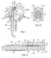
- the section of the curved core 60should be advantageously polygonal. However, it can be for example circular, but in this case it will be added, as more particularly visible on the figure 10 at least one pair, preferably two opposite pairs, comprising a groove 91 made in one of the two following elements: the curved core 60 and one of the parts 11-1, 11-2 of the elongate body 11, and a rib 92 complementary to the groove 91 and made in the other of the two elements, so that the rib 92 is able to slide in the groove 91.
- the groove 91is made in one of the parts 11-1, 11-2 of the elongate body 11, while the rib 92 is formed on the curved core 60.
- the groove 91 and the rib 92cooperate in a well-known dovetail assembly in itself.
- the systemcomprises a guide rod 50.
- this guide rod 50consists of a hollow tube 55 and the push rod 80 is then slidably mounted in this hollow tube.
- the means 70 for mounting the first end 61 of the curved core 60 in cooperation with the first end 51 of the guide rod 50are then constituted by means for fixing the first end 61 of the curved core 60 on the wall of the hollow tube and in continuity therewith.
- the hollow tube 55 and the curved core 60may be made in two separate parts and secured together, or in one piece made from a single hollow tube.
- the Practitionerfirst incisions the back of the patient to create a path of introduction that passes between the two nerves whose vital aspect is well known to Practitioners.
- FIGURES 1 to 5 and 11the Practitioner introduces, by this incision, the insertion guide 40 with the curved core 60 already introduced entirely into the piercing 13 of the elongated body 11. In this way, the cage 10 is almost totally in continuity with the hollow tube 55, as illustrated on the figure 3 . This configuration easily allows the introduction of the cage 10 between the two vertebrae V1, V2 passing between the two nerves.
- the Practitionerpushes the push rod 80 into the hollow tube 55 so that its end 81 comes into contact with the end 14 of the oblong body 11. It continues to push on the push rod 80 and, under the effect of this push , the elongated body 11 moves relative to the curved core 60 along the curved axis 12 to its final position ( figure 5 ), replacing the intervertebral disk between the two vertebrae V1, V2, that is to say having it rotated about ninety degrees relative to its direction of introduction.
- the curved core 60is completely out of the piercing 13 and the insertion guide 40 can be removed in the opposite direction of the path followed for its introduction.
- FIGURES 6 to 10 and 11the Practitioner introduces, by the incision made previously, the introduction guide 40 with the curved core 60 introduced entirely into the piercing 13 of the elongated body 11. In this way, the cage 10 is almost completely in continuity with the hollow tube 55 as shown on the figure 6 , and this configuration easily allows the introduction of the cage 10 between the two vertebrae V1, V2 passing between the two nerves and other vital organs.
- the elongate body 11consisting of two parts 211, 212 separated from one another, they are mounted cooperatively so that the two ribs 92 made on the curved core 60 are mounted sliding in the two grooves 91 formed respectively on the two parts 211, 212.
- the three elements: the curved core 60 and the two parts 211, 212are well maintained relative to each other.
- the positioning of the cage between the two vertebrae V1, V2is carried out as described above with regard to the Figures 1 to 5 and 11 for the first embodiment of the system.
- the two pieces 211, 212are separated from each other and the sections of the curved core 60 are increasing as previously defined, by pushing these two pieces 211, 212 relative to the soul curve 60, as they move, they gradually move away from each other, as illustrated by the four Figures 6 to 9 until they take their final position, figure 9 .
- This second embodimentmakes it possible, as it were, to position simultaneously two half-cages 211, 212 remote from one another to better fill the intervertebral space instead of the original intervertebral disc, with the possibility of placing, in this space 13, for example a bone graft or the like.
Landscapes
- Health & Medical Sciences (AREA)
- Engineering & Computer Science (AREA)
- Biomedical Technology (AREA)
- Orthopedic Medicine & Surgery (AREA)
- Transplantation (AREA)
- Neurology (AREA)
- Oral & Maxillofacial Surgery (AREA)
- Cardiology (AREA)
- Heart & Thoracic Surgery (AREA)
- Vascular Medicine (AREA)
- Life Sciences & Earth Sciences (AREA)
- Animal Behavior & Ethology (AREA)
- General Health & Medical Sciences (AREA)
- Public Health (AREA)
- Veterinary Medicine (AREA)
- Physical Education & Sports Medicine (AREA)
- Prostheses (AREA)
Description
Translated fromFrenchLa présente invention concerne les systèmes pour remplacer un disque intervertébral.The present invention relates to systems for replacing an intervertebral disc.
Il est connu que, selon les traumatismes subis par une colonne vertébrale, les praticiens sont amenés à effectuer deux sortes d'intervention chirurgicale.It is known that, depending on the trauma suffered by a spine, practitioners are required to perform two types of surgery.
Quand le traumatisme ne concerne qu'un disque intervertébral et que les deux vertèbres consécutives encadrant ce disque sont en bon état, le praticien peut opter pour le remplacement du disque par une prothèse dont la fonctionnalité est sensiblement équivalente à celle du disque originel, c'est-à-dire laissant aux deux vertèbres la possibilité de se déplacer l'une par rapport à l'autre dans des mouvements de rotation et/ou de translation.When the trauma concerns only one intervertebral disc and the two consecutive vertebrae surrounding this disc are in good condition, the practitioner can opt for the replacement of the disc by a prosthesis whose functionality is substantially equivalent to that of the original disc. that is to say leaving the two vertebrae the ability to move relative to each other in rotational and / or translational movements.
En revanche, quand le traumatisme est plus important, le praticien peut choisir de solidariser les deux vertèbres consécutives par ostéosynthèse. Pour ce faire, le disque intervertébral est partiellement ou en totalité détruit et remplacé par une cage intersomatique associée généralement à un élément favorisant l'ostéosynthèse, par exemple un greffon osseux.On the other hand, when the trauma is greater, the practitioner can choose to secure the two consecutive vertebrae by osteosynthesis. To do this, the intervertebral disk is partially or completely destroyed and replaced by an intersomatic cage generally associated with an osteosynthesis promoting element, for example a bone graft.
Ces cages intersomatiques sont implantables essentiellement par deux voies, l'une dite "antérieure", l'autre dite "postérieure", chacune de ces voies ayant ses avantages et ses inconvénients.These intersomatic cages are essentially implantable by two ways, one called "anterior", the other called "posterior", each of these routes having its advantages and disadvantages.
Il semblerait cependant évident que l'implantation par la voie postérieure soit la plus normale car le chemin utilisé par le praticien pour l'intervention chirurgicale est relativement court. Mais elle est très délicate car ce chemin passe très près d'éléments essentiels pour la vie du patient, à savoir la moelle épinière et les deux nerfs qui commandent notamment les mouvements du patient.However, it seems obvious that the posterior implantation is the most normal because the path used by the practitioner for the surgical procedure is relatively short. But it is very delicate because this path passes very close to essential elements for the life of the patient, namely the spinal cord and the two nerves that control the movements of the patient.
C'est pour cette raison que certains praticiens optent parfois pour la voie dite "antérieure" qui implique un chemin d'intervention beaucoup plus long, mais en théorie moins dangereux pour le patient. A contrario, le temps d'intervention est plus long que celui par la voie postérieure, ce qui peut présenter un inconvénient pour la santé et la récupération du patient.It is for this reason that some practitioners sometimes opt for the so-called "anterior" pathway which involves a much longer intervention path, but in theory less dangerous for the patient. Conversely, the intervention time is longer than that by the posterior route, which can be a disadvantage for the health and recovery of the patient.
Aussi a-t-il été réalisé des nombreux systèmes pour remplacer un disque entre deux vertèbres consécutives, qui permet une implantation par la voie notamment postérieure.So it has been realized many systems to replace a disc between two consecutive vertebrae, which allows implantation by the particular posterior route.
De tels systèmes sont par exemple décrits et illustrés dans le
Le Demandeur a, lui aussi, réalisé de tels systèmes, par exemple celui décrit dans le
La présente invention a cependant pour but de réaliser un système pour remplacer un disque entre deux vertèbres consécutives, qui permet une implantation par la voie postérieure, qui soit d'une structure plus simple, et donc moins encombrante et plus facile à utiliser que celle des systèmes de l'art antérieur en ce domaine, par exemple ceux définis dans les documents précités.The object of the present invention is however to provide a system for replacing a disc between two consecutive vertebrae, which allows implantation by the posterior route, which is of a simpler structure, and therefore less cumbersome and easier to use than that of the systems of the prior art in this field, for example those defined in the aforementioned documents.
Plus précisément, la présente invention a pour objet un système pour remplacer un disque entre deux vertèbres consécutives, telle que définie dans la revendication 1 annexée dont le préambule contient les caractéristiques du dispositif divulgué dans le
D'autres caractéristiques et avantages de l'invention apparaîtront au cours de la description suivante donnée en regard des dessins annexés à titre illustratif mais nullement limitatif, dans lesquels :
- La
figure 1 représente, de façon très schématique, un mode de réalisation du système selon l'invention pour remplacer un disque entre deux vertèbres consécutives, - Les
figures 2 à 5 représentent différentes configurations du système selon l'invention dans le mode de réalisation selon lafigure 1 , lafigure 2 représentant le système sans son élément "cage", lafigure 3 représentant le système dans sa configuration initiale, la cage étant déjà interposée entre deux vertèbres, lafigure 4 représentant le système dans une configuration intermédiaire, la cage étant positionnée dans un état proche de sa position finale, et lafigure 5 représentant le système avec la cage dans son état final, - Les
figures 6 à 9 représentent différentes configurations du mode de réalisation du système selon lafigure 1 dans son utilisation pour l'implantation d'une cage ayant une autre structure que celle selon lesfigures 1 à 5 , lafigure 6 représentant le système dans sa configuration initiale, la cage étant déjà interposée entre les deux vertèbres en situation initiale, lesfigures 7 et8 représentant le système respectivement dans deux configurations intermédiaires, et lafigure 9 représentant le système avec la cage en situation finale, et - Les
figures 10 et 11 représentent, de façon schématique, respectivement deux coupes du système selon l'invention permettant d'expliciter sa structure, lafigure 10 représentant une coupe partielle du système référencée X-X sur lafigure 7 et lafigure 11 représentant une coupe du système référencée XI-XI sur lafigure 1 .
- The
figure 1 represents, very schematically, an embodiment of the system according to the invention for replacing a disk between two consecutive vertebrae, - The
Figures 2 to 5 represent different configurations of the system according to the invention in the embodiment according to thefigure 1 , thefigure 2 representing the system without its element "cage", thefigure 3 representing the system in its initial configuration, the cage being already interposed between two vertebrae, thefigure 4 representing the system in an intermediate configuration, the cage being positioned in a state close to its final position, and thefigure 5 representing the system with the cage in its final state, - The
Figures 6 to 9 represent different configurations of the embodiment of the system according to thefigure 1 in its use for the implantation of a cage having a structure other than that according to theFigures 1 to 5 , thefigure 6 representing the system in its initial configuration, the cage being already interposed between the two vertebrae in initial situation, thefigures 7 and8 representing the system respectively in two intermediate configurations, and thefigure 9 representing the system with the cage in final situation, and - The
Figures 10 and 11 represent, schematically, respectively two sections of the system according to the invention making it possible to explain its structure, thefigure 10 representing a partial section of the referenced system XX on thefigure 7 and thefigure 11 representing a section of the system referenced XI-XI on thefigure 1 .
II est précisé que les figures représentent essentiellement deux modes de réalisation de l'objet selon l'invention, mais qu'il peut exister d'autres modes de réalisation qui répondent à la définition de cette invention.It should be noted that the figures essentially represent two embodiments of the object according to the invention, but that there may be other embodiments that meet the definition of this invention.
En référence plus particulièrement à la
Par cage intervertébrale 10 au sens de la présente invention, on entend une cage intervertébrale proprement dite selon la terminaison des hommes du métier, ainsi que tout corps apte à être introduit entre deux vertèbres, qu'il soit en une seule partie ou en plusieurs, quelles que soient sa ou ses fonctions, par exemple une prothèse discale. L'expression "cage intervertébrale" n'est utilisée ici que pour simplifier et faciliter la compréhension de l'invention et de sa description.By
Selon une caractéristique essentielle de l'invention, la cage intervertébrale 10 est constituée d'un corps oblong 11 délimité entre deux faces opposées sensiblement planes, le corps oblong comportant au moins deux parties 11-1, 11-2 séparées par un espace 13, cet espace étant défini suivant un axe courbe 12 contenu dans un plan médian sensiblement parallèle aux plans des faces opposées et débouchant par une ouverture 15 à une première extrémité 14 du corps oblong 11 entre les deux parties 11-1, 11-2 du corps oblong.According to an essential characteristic of the invention, the
Selon une autre caractéristique de l'invention, le guide d'introduction 40 est constitué d'au moins une tige de guidage 50, dont un exemple avantageux de mode de réalisation sera décrit ci-après, et une âme longitudinale courbe 60 dont les sections transversales sont sensiblement complémentaires de celles de l'espace 13, de façon à permettre un coulissement respectif entre l'âme courbe et les deux parties 11-1, 11-2 du corps oblong 11.According to another characteristic of the invention, the
Deux exemples de réalisation de cette âme courbe 60 seront donnés ci-après en regard respectivement des
Sont aussi prévus des moyens 70 pour monter une première extrémité 61 de l'âme courbe 60 en coopération avec une première extrémité 51 de la tige de guidage 50 de façon que cette âme courbe soit en saillie par rapport à cette première extrémité 51 de la tige de guidage, et une tige poussoir 80 montée en déplacement par rapport à la tige de guidage 50 de façon qu'elle soit apte à venir au contact, par une 81 de ses extrémités, contre la première extrémité 14 du corps oblong 11 pour pousser ce corps oblong en translation par rapport à l'âme courbe 60.Also provided means 70 for mounting a
Selon une première réalisation possible, le corps oblong 11 est constitué d'une pièce unique 111 et l'espace 13 est constitué d'une percée réalisée dans la pièce unique sensiblement suivant l'axe courbe 12 défini précédemment.According to a first possible embodiment, the
Il est aussi avantageux que cette percée soit ouverte sur les deux faces opposées de la cage intervertébrale 10 sensiblement planes de façon à pouvoir éventuellement y placer un greffon osseux ou analogue.It is also advantageous if this breakthrough is open on the two opposite faces of the
De façon avantageuse, comme illustré, la pièce unique 111 a sensiblement la forme d'un "haricot" ou assimilé, mais à faces opposées sensiblement planes.Advantageously, as illustrated, the
Dans ce cas, selon les
Selon une première possibilité, pour empêcher que la pièce unique 111 ne puisse pivoter au moins partiellement autour de l'âme courbe 60, mais en revanche pour permettre à cette pièce unique 111 de coulisser par rapport à cette âme courbe, il est très préférable que les sections transversales de cette âme courbe 60, définies dans des plans perpendiculaires à l'axe courbe 12, soient de forme polygonale. Comme exemple, dans le mode de réalisation illustré sur la
En se référant maintenant plus particulièrement au mode de réalisation selon les
Dans ce cas, dans le but explicité ci-après, il est possible, et même avantageux, que les sections transversales de l'âme courbe 60 définies dans des plans perpendiculaires à l'axe courbe 12 aient des valeurs croissantes de façon sensiblement continue à partir de sa première extrémité 61 jusqu'à sa seconde extrémité libre 62 opposée à la première.In this case, for the purpose explained below, it is possible, and even advantageous, that the cross sections of the
Cependant, bien que le mode de réalisation décrit ci-dessus soit souvent très avantageux, il est possible que les sections transversales de l'âme courbe 60 définies dans des plans perpendiculaires à l'axe courbe 12 soient sensiblement identiques entre elles.However, although the embodiment described above is often very advantageous, it is possible that the cross sections of the
Il a été mentionné que la section de l'âme courbe 60 devait être avantageusement polygonale. Cependant, elle peut être par exemple circulaire, mais dans ce cas on lui adjoindra, comme plus particulièrement visible sur la
Sur la
De façon avantageuse, comme dans le mode de réalisation illustré sur cette
Comme mentionné précédemment, le système comporte une tige de guidage 50. Comme illustré et plus particulièrement visible sur la
Le tube creux 55 et l'âme courbe 60 peuvent être réalisés en deux pièces séparées et solidarisées ensemble, ou d'une seule pièce réalisée à partir d'un tube creux unique. Ces réalisations sont du domaine de l'homme du métier ne seront pas plus amplement décrites ici par l'unique souci de simplifier la présente description.The
Le système selon l'invention et selon les deux modes de réalisation respectivement
De façon connue, le Praticien pratique d'abord une incision dans le dos du patient pour créer un chemin d'introduction qui passe notamment entre les deux nerfs dont l'aspect vital est bien connu des Praticiens.In known manner, the Practitioner first incisions the back of the patient to create a path of introduction that passes between the two nerves whose vital aspect is well known to Practitioners.
PREMIER MODE DE REALISATION DU SYSTEME.
Quand la cage est positionnée comme illustré sur la
Lorsque la cage 10 arrive dans sa position finale, l'âme courbe 60 est totalement sortie de la percée 13 et le guide d'introduction 40 peut être retiré en sens inverse du chemin suivi pour son introduction.When the
SECOND MODE DE REALISATION DU SYSTEME,
Cependant, dans ce cas, le corps oblong 11 étant constitué de deux pièces 211, 212 séparées l'une de l'autre, celles-ci sont montées en coopération de façon que les deux nervures 92 réalisées sur l'âme courbe 60 soient montées coulissantes dans les deux rainures 91 réalisées respectivement sur les deux pièces 211, 212. De cette façon les trois éléments : l'âme courbe 60 et les deux pièces 211, 212 sont bien maintenus les uns par rapport aux autres.However, in this case, the
Le positionnement de la cage entre les deux vertèbres V1, V2 s'effectue comme décrit ci-dessus en regard des
Cette seconde réalisation permet, en quelque sorte, de positionner simultanément deux demi-cages 211, 212 éloignées l'une de l'autre pour mieux remplir l'espace intervertébral en remplacement du disque intervertébral originel, avec la possibilité de placer, dans cet espace 13, par exemple un greffon osseux ou analogue.This second embodiment makes it possible, as it were, to position simultaneously two half-
Bien entendu, il est aussi possible d'utiliser le système selon l'invention avec une cage en deux parties 211, 212 séparées l'une de l'autre et une âme courbe 60 ayant une section uniforme sur toute sa longueur, et non croissante comme dans le mode de réalisation ci-dessus.Of course, it is also possible to use the system according to the invention with a cage in two
Claims (11)
- A system for replacing a disk between two consecutive vertebrae (V1, V2) comprising at least one intervertebral cage (10) and an introducer guide (40) for introducing said intervertebral cage between the two vertebrae, said intervertebral cage (10) being constituted by an oblong body (11) defined between two substantially parallel opposite faces, said oblong body comprising at least two portions (11-1, 11-2) separated by a gap (13), said gap being defined along a curved axis (12) contained in a midplane substantially parallel to the planes of the opposite faces and opening out via an opening (15) at a first end (14) of the oblong body (11) between said two portions (11-1, 11-2) of said oblong body; and the introducer guide (40) being constituted by at least a guide rod (50);
characterized by the fact that said introducer guide is constituted besides by:· a curved longitudinal core (60) of cross-sections that are substantially complementary to the cross-sections of said space (13), so as to enable said curved core to slide relative to the two portions (11-1, 11-2) of said oblong body (11);· means (70) for mounting a first end (61) of said curved core (60) to co-operate with a first end (51) of said guide rod (50) in such a manner that said curved core (60) projects from said first end (51) of said guide rod (50); and· a push rod (80) mounted to move relative to said guide rod (50) in such a manner as to be suitable for coming into contact via one of its ends (81) against the first end (14) of the oblong body (11) in order to push said oblong body in translation relative to said curved core (60). - A system according to claim 1,characterized by the fact that said oblong body (11) is constituted by a single part (111) and that said gap (13) is constituted by a hole formed in said single part, substantially along said curved axis (12).
- A system according to claim 1,characterized by the fact that the single part (111) is substantially in the shape of a kidney bean having opposite faces that are substantially plane.
- A system according to claim 2 or claim 3,characterized by the fact that all of the cross-sections of said curved core (60), as defined in planes perpendicular to said curved axis (12), are substantially mutually identical.
- A system according to claim 4,characterized by the fact that the cross-sections of said curved core (60), defined in planes perpendicular to said curved axis (12), are polygonal in shape.
- A system according to claim 1,characterized by the fact that the two portions (11-1, 11-2) of said oblong body (11) are constituted by two mutually separate parts (211, 212).
- A system according to claim 6,characterized by the fact that the cross-sections of said curved core (60), defined in planes perpendicular to said curved axis (12), are of values that increase substantially continuously from its first end (61) to its free second or other end (62) opposite from the first.
- A system according to claim 6,characterized by the fact that all of the cross-sections of said curved core (60), as defined in planes perpendicular to said curved axis (12), are substantially mutually identical.
- A system according to any preceding claim,characterized by the fact that it further includes at least one groove-and-rib pair comprising both a groove (91) formed in one of the following two elements: the curved core (60) and one of the portions (11-1, 11-2) of said oblong body (11), and also a rib (92) complementary to said groove (91), said rib being made on the other one of the two elements in such a manner that said rib (92) is suitable for sliding in said groove (91).
- A system according to claim 9,characterized by the fact that said groove (91) and said rib (92) co-operate by dovetail mounting.
- A system according to any preceding claim,characterized by the fact that said guide rod (50) is constituted by a hollow tube (55), that the push rod (80) is slidably mounted in said hollow tube, and that the means (70) for mounting the first end (61) of said curved core (60) in co-operation with the first end (51) of said guide rod (50) are constituted by fastener means for fastening the first end (61) of said curved core (60) on the wall of said hollow tube and in continuity therewith.
Applications Claiming Priority (2)
| Application Number | Priority Date | Filing Date | Title |
|---|---|---|---|
| FR1001398AFR2958151B1 (en) | 2010-04-06 | 2010-04-06 | SYSTEM FOR REPLACING AN INTERVERTEBRAL DISC. |
| PCT/FR2011/000197WO2011124787A1 (en) | 2010-04-06 | 2011-04-05 | System for replacing an intervertebral disc |
Publications (2)
| Publication Number | Publication Date |
|---|---|
| EP2555714A1 EP2555714A1 (en) | 2013-02-13 |
| EP2555714B1true EP2555714B1 (en) | 2014-01-01 |
Family
ID=43333194
Family Applications (1)
| Application Number | Title | Priority Date | Filing Date |
|---|---|---|---|
| EP11730347.9AActiveEP2555714B1 (en) | 2010-04-06 | 2011-04-05 | System for replacing an intervertebral disc |
Country Status (5)
| Country | Link |
|---|---|
| US (1) | US8845735B2 (en) |
| EP (1) | EP2555714B1 (en) |
| ES (1) | ES2451843T3 (en) |
| FR (1) | FR2958151B1 (en) |
| WO (1) | WO2011124787A1 (en) |
Families Citing this family (13)
| Publication number | Priority date | Publication date | Assignee | Title |
|---|---|---|---|---|
| US9198765B1 (en) | 2011-10-31 | 2015-12-01 | Nuvasive, Inc. | Expandable spinal fusion implants and related methods |
| CN104582639A (en) | 2012-05-29 | 2015-04-29 | Nlt-脊椎有限公司 | Laterally deflectable implant |
| FR2992167B1 (en)* | 2012-06-25 | 2014-08-29 | Hassan Razian | IMPROVED SYSTEM FOR REPLACING AN INTERVERTEBRAL DISC |
| US9278011B2 (en)* | 2012-08-08 | 2016-03-08 | Spectrum Spine Ip Holdings, Llc | Percutaneous cage delivery systems devices and methods |
| US10154914B2 (en) | 2012-08-08 | 2018-12-18 | Spectrum Spine Ip Holdings, Llc | Expandable intervertebral cage assemblies |
| US20160022434A1 (en) | 2012-08-08 | 2016-01-28 | James C. Robinson | Expandable intervertebral cage assemblies |
| CN104955409B (en) | 2012-08-08 | 2018-03-30 | 詹姆斯·C·罗宾逊 | Expandable intervertebral cage assembly and method |
| US9445918B1 (en) | 2012-10-22 | 2016-09-20 | Nuvasive, Inc. | Expandable spinal fusion implants and related instruments and methods |
| FR3029099B1 (en)* | 2014-11-27 | 2019-04-05 | Hassan Razian | SYSTEM FOR APPLYING AN ELEMENT ON A PORTION OF THE WALL OF A BONE CAVITY |
| FR3063890B1 (en)* | 2017-03-17 | 2022-03-04 | Hassan Razian | SYSTEM FOR POSITIONING AN INSERT BETWEEN TWO BONE PORTIONS |
| CN107789100B (en)* | 2017-12-08 | 2024-04-12 | 河北瑞鹤医疗器械有限公司 | Fusion device pusher |
| FR3091648B1 (en) | 2019-01-10 | 2020-12-25 | Razian Hassan | Intervertebral cage |
| JP7624252B1 (en)* | 2023-12-19 | 2025-01-30 | リーガエース株式会社 | A system for guiding an interbody spacer between vertebral bodies |
Family Cites Families (15)
| Publication number | Priority date | Publication date | Assignee | Title |
|---|---|---|---|---|
| DE19903762C1 (en) | 1999-01-30 | 2000-11-16 | Aesculap Ag & Co Kg | Surgical instrument for inserting intervertebral implants |
| FR2897259B1 (en)* | 2006-02-15 | 2008-05-09 | Ldr Medical Soc Par Actions Si | INTERSOMATIC TRANSFORAMINAL CAGE WITH INTERBREBAL FUSION GRAFT AND CAGE IMPLANTATION INSTRUMENT |
| KR100371308B1 (en)* | 2000-08-28 | 2003-02-07 | 구자교 | a prosthetic implant for spinal interbody fusion and a inserting apparatus thereof |
| US7806932B2 (en) | 2003-08-01 | 2010-10-05 | Zimmer Spine, Inc. | Spinal implant |
| FR2861582B1 (en) | 2003-10-29 | 2006-02-10 | Eurosurgical | INTERSOMATIC CAGE FOR LUMBAR FUSION FIRST TRANSFORAMINAL AND CAGE HOLDER DEVICE |
| US7575580B2 (en)* | 2005-04-15 | 2009-08-18 | Warsaw Orthopedic, Inc. | Instruments, implants and methods for positioning implants into a spinal disc space |
| US8696681B2 (en)* | 2005-09-29 | 2014-04-15 | K2M, Inc. | Adjustable interbody introducer device and method |
| US8157845B2 (en)* | 2006-03-22 | 2012-04-17 | Beacon Biomedical, Llc | Pivotable vetrebral spacer |
| WO2008115975A1 (en)* | 2006-03-22 | 2008-09-25 | Alpinespine Llc | Pivotable interbody spacer system and method |
| US7794501B2 (en)* | 2006-04-27 | 2010-09-14 | Wasaw Orthopedic, Inc. | Expandable intervertebral spacers and methods of use |
| US8034110B2 (en)* | 2006-07-31 | 2011-10-11 | Depuy Spine, Inc. | Spinal fusion implant |
| US8454621B2 (en)* | 2006-09-19 | 2013-06-04 | Warsaw Orthopedic, Inc. | Instruments and methods for spinal implant revision |
| US8163026B2 (en)* | 2007-04-05 | 2012-04-24 | Zimmer Spine, Inc. | Interbody implant |
| FR2914842B1 (en) | 2007-04-10 | 2009-06-26 | Hassan Razian | SYSTEM FOR REPLACING A DISC BETWEEN TWO VERTEBRATES |
| US20120277866A1 (en)* | 2011-04-28 | 2012-11-01 | Prakasam Kalluri | Angled Bullet-Nose Banana Cage |
- 2010
- 2010-04-06FRFR1001398Apatent/FR2958151B1/ennot_activeExpired - Fee Related
- 2011
- 2011-04-05ESES11730347.9Tpatent/ES2451843T3/enactiveActive
- 2011-04-05USUS13/639,118patent/US8845735B2/enactiveActive
- 2011-04-05EPEP11730347.9Apatent/EP2555714B1/enactiveActive
- 2011-04-05WOPCT/FR2011/000197patent/WO2011124787A1/enactiveApplication Filing
Also Published As
| Publication number | Publication date |
|---|---|
| WO2011124787A1 (en) | 2011-10-13 |
| ES2451843T3 (en) | 2014-03-28 |
| US20130023997A1 (en) | 2013-01-24 |
| FR2958151A1 (en) | 2011-10-07 |
| EP2555714A1 (en) | 2013-02-13 |
| US8845735B2 (en) | 2014-09-30 |
| FR2958151B1 (en) | 2012-04-27 |
Similar Documents
| Publication | Publication Date | Title |
|---|---|---|
| EP2555714B1 (en) | System for replacing an intervertebral disc | |
| EP1632199B1 (en) | Implant for fixing of an osseous graft within a joint to assure the arthrodesis of the joint | |
| EP1299054B1 (en) | Intersomatic implant | |
| FR2913331A1 (en) | Intersomatic cage for being intercalated between two consecutive vertebrae, has elementary cages mounted such that planes of parts form angle when parts are in open position, and faces contact each other when parts are in closed position | |
| EP2231074B1 (en) | Intervertebral stabilization assembly for arthrodesis, comprising an impaction cage body, and an ancillary device for implanting same | |
| EP1720472B1 (en) | Dynamic linking element for a spinal attachment system, and spinal attachment system including said linking element | |
| FR2900814A1 (en) | INTERSOMATIC CAGE MAY BE INTERCALE BETWEEN TWO CONSECUTIVE VERTEBRA, AND INSTRUMENT FOR IMPLANTING SUCH AN INTERSOMATIC CAGE BETWEEN TWO CONSECUTIVE VERTEBERS | |
| EP1988838B1 (en) | Intervertebral implant | |
| FR2914842A1 (en) | SYSTEM FOR REPLACING A DISC BETWEEN TWO VERTEBRATES | |
| FR2858546A1 (en) | INTERVERTEBRAL DISC PROSTHESIS | |
| EP2547291B1 (en) | Knee prosthesis having a mixed meniscal plate | |
| FR2916956A1 (en) | INTERSOMATIC CAGE, INTERVERTEBRAL PROSTHESIS, ANCHORING DEVICE AND IMPLANTATION INSTRUMENTATION | |
| WO2019063807A1 (en) | Ankle prosthesis comprising a talar implant, a tibial implant and an insert, and kit including at least one such prosthesis | |
| EP1414358A2 (en) | Vertebra stabilizing assembly | |
| FR2943529A1 (en) | Intervertebral disc prosthesis for patient, has control unit controlling displacement of intermediate body between two positions, and connecting units connecting body with one of two plates and vertebra when body is in one of positions | |
| FR2943530A1 (en) | Prosthetic disc for being interposed between adjacent vertebrae to replace damaged intervertebral disc at origin between vertebrae, has plates that are associated, such that sliding surfaces cooperate with each other by sliding in rotation | |
| WO2010037926A1 (en) | Intervertebral disc | |
| FR2951370A1 (en) | Intervertebral implant for replacing intervertebral disk to join patient's vertebrae, has anterior and posterior elements movable between opening and closing positions obtained by pivotment during contact of anterior element against plate | |
| FR3054788A1 (en) | DEPLOYABLE IMPLANT | |
| FR2684291A1 (en) | Ankle prosthesis | |
| WO2012140387A2 (en) | Intervertebral disc prosthesis and intervertebral prosthetic unit | |
| FR2992167A1 (en) | System for replacing disk between two consecutive vertebrae, has intervertebral cage including oblong body, where opposite faces are covered with protuberances that are treated with product for fixing of two vertebrae on bone | |
| FR2923158A1 (en) | INTERVERTEBRAL IMPLANT FOR IMMOBILIZING A VERTEBRE IN RELATION TO ANOTHER AND INSTRUMENT OF INSTALLATION OF THIS IMPLANT. | |
| FR2726759A1 (en) | Osteosynthesis implant for fusing adjacent vertebrae | |
| FR3091648A1 (en) | Intervertebral cage |
Legal Events
| Date | Code | Title | Description |
|---|---|---|---|
| PUAI | Public reference made under article 153(3) epc to a published international application that has entered the european phase | Free format text:ORIGINAL CODE: 0009012 | |
| 17P | Request for examination filed | Effective date:20120925 | |
| AK | Designated contracting states | Kind code of ref document:A1 Designated state(s):AL AT BE BG CH CY CZ DE DK EE ES FI FR GB GR HR HU IE IS IT LI LT LU LV MC MK MT NL NO PL PT RO RS SE SI SK SM TR | |
| DAX | Request for extension of the european patent (deleted) | ||
| GRAP | Despatch of communication of intention to grant a patent | Free format text:ORIGINAL CODE: EPIDOSNIGR1 | |
| INTG | Intention to grant announced | Effective date:20130823 | |
| GRAS | Grant fee paid | Free format text:ORIGINAL CODE: EPIDOSNIGR3 | |
| GRAA | (expected) grant | Free format text:ORIGINAL CODE: 0009210 | |
| AK | Designated contracting states | Kind code of ref document:B1 Designated state(s):AL AT BE BG CH CY CZ DE DK EE ES FI FR GB GR HR HU IE IS IT LI LT LU LV MC MK MT NL NO PL PT RO RS SE SI SK SM TR | |
| REG | Reference to a national code | Ref country code:GB Ref legal event code:FG4D Free format text:NOT ENGLISH | |
| REG | Reference to a national code | Ref country code:CH Ref legal event code:EP | |
| REG | Reference to a national code | Ref country code:IE Ref legal event code:FG4D Free format text:LANGUAGE OF EP DOCUMENT: FRENCH | |
| REG | Reference to a national code | Ref country code:AT Ref legal event code:REF Ref document number:647253 Country of ref document:AT Kind code of ref document:T Effective date:20140215 | |
| REG | Reference to a national code | Ref country code:DE Ref legal event code:R096 Ref document number:602011004489 Country of ref document:DE Effective date:20140220 | |
| REG | Reference to a national code | Ref country code:CH Ref legal event code:NV Representative=s name:BOVARD AG, CH | |
| REG | Reference to a national code | Ref country code:ES Ref legal event code:FG2A Ref document number:2451843 Country of ref document:ES Kind code of ref document:T3 Effective date:20140328 | |
| REG | Reference to a national code | Ref country code:NL Ref legal event code:VDEP Effective date:20140101 | |
| REG | Reference to a national code | Ref country code:AT Ref legal event code:MK05 Ref document number:647253 Country of ref document:AT Kind code of ref document:T Effective date:20140101 | |
| REG | Reference to a national code | Ref country code:LT Ref legal event code:MG4D | |
| PG25 | Lapsed in a contracting state [announced via postgrant information from national office to epo] | Ref country code:LT Free format text:LAPSE BECAUSE OF FAILURE TO SUBMIT A TRANSLATION OF THE DESCRIPTION OR TO PAY THE FEE WITHIN THE PRESCRIBED TIME-LIMIT Effective date:20140101 Ref country code:IS Free format text:LAPSE BECAUSE OF FAILURE TO SUBMIT A TRANSLATION OF THE DESCRIPTION OR TO PAY THE FEE WITHIN THE PRESCRIBED TIME-LIMIT Effective date:20140501 | |
| PG25 | Lapsed in a contracting state [announced via postgrant information from national office to epo] | Ref country code:AT Free format text:LAPSE BECAUSE OF FAILURE TO SUBMIT A TRANSLATION OF THE DESCRIPTION OR TO PAY THE FEE WITHIN THE PRESCRIBED TIME-LIMIT Effective date:20140101 Ref country code:NL Free format text:LAPSE BECAUSE OF FAILURE TO SUBMIT A TRANSLATION OF THE DESCRIPTION OR TO PAY THE FEE WITHIN THE PRESCRIBED TIME-LIMIT Effective date:20140101 Ref country code:CY Free format text:LAPSE BECAUSE OF FAILURE TO SUBMIT A TRANSLATION OF THE DESCRIPTION OR TO PAY THE FEE WITHIN THE PRESCRIBED TIME-LIMIT Effective date:20140101 Ref country code:PT Free format text:LAPSE BECAUSE OF FAILURE TO SUBMIT A TRANSLATION OF THE DESCRIPTION OR TO PAY THE FEE WITHIN THE PRESCRIBED TIME-LIMIT Effective date:20140502 Ref country code:FI Free format text:LAPSE BECAUSE OF FAILURE TO SUBMIT A TRANSLATION OF THE DESCRIPTION OR TO PAY THE FEE WITHIN THE PRESCRIBED TIME-LIMIT Effective date:20140101 Ref country code:SE Free format text:LAPSE BECAUSE OF FAILURE TO SUBMIT A TRANSLATION OF THE DESCRIPTION OR TO PAY THE FEE WITHIN THE PRESCRIBED TIME-LIMIT Effective date:20140101 | |
| PG25 | Lapsed in a contracting state [announced via postgrant information from national office to epo] | Ref country code:RS Free format text:LAPSE BECAUSE OF FAILURE TO SUBMIT A TRANSLATION OF THE DESCRIPTION OR TO PAY THE FEE WITHIN THE PRESCRIBED TIME-LIMIT Effective date:20140101 Ref country code:LV Free format text:LAPSE BECAUSE OF FAILURE TO SUBMIT A TRANSLATION OF THE DESCRIPTION OR TO PAY THE FEE WITHIN THE PRESCRIBED TIME-LIMIT Effective date:20140101 Ref country code:HR Free format text:LAPSE BECAUSE OF FAILURE TO SUBMIT A TRANSLATION OF THE DESCRIPTION OR TO PAY THE FEE WITHIN THE PRESCRIBED TIME-LIMIT Effective date:20140101 | |
| REG | Reference to a national code | Ref country code:DE Ref legal event code:R097 Ref document number:602011004489 Country of ref document:DE | |
| PG25 | Lapsed in a contracting state [announced via postgrant information from national office to epo] | Ref country code:RO Free format text:LAPSE BECAUSE OF FAILURE TO SUBMIT A TRANSLATION OF THE DESCRIPTION OR TO PAY THE FEE WITHIN THE PRESCRIBED TIME-LIMIT Effective date:20140101 Ref country code:EE Free format text:LAPSE BECAUSE OF FAILURE TO SUBMIT A TRANSLATION OF THE DESCRIPTION OR TO PAY THE FEE WITHIN THE PRESCRIBED TIME-LIMIT Effective date:20140101 Ref country code:DK Free format text:LAPSE BECAUSE OF FAILURE TO SUBMIT A TRANSLATION OF THE DESCRIPTION OR TO PAY THE FEE WITHIN THE PRESCRIBED TIME-LIMIT Effective date:20140101 Ref country code:CZ Free format text:LAPSE BECAUSE OF FAILURE TO SUBMIT A TRANSLATION OF THE DESCRIPTION OR TO PAY THE FEE WITHIN THE PRESCRIBED TIME-LIMIT Effective date:20140101 | |
| PLBE | No opposition filed within time limit | Free format text:ORIGINAL CODE: 0009261 | |
| STAA | Information on the status of an ep patent application or granted ep patent | Free format text:STATUS: NO OPPOSITION FILED WITHIN TIME LIMIT | |
| PG25 | Lapsed in a contracting state [announced via postgrant information from national office to epo] | Ref country code:LU Free format text:LAPSE BECAUSE OF FAILURE TO SUBMIT A TRANSLATION OF THE DESCRIPTION OR TO PAY THE FEE WITHIN THE PRESCRIBED TIME-LIMIT Effective date:20140405 Ref country code:SK Free format text:LAPSE BECAUSE OF FAILURE TO SUBMIT A TRANSLATION OF THE DESCRIPTION OR TO PAY THE FEE WITHIN THE PRESCRIBED TIME-LIMIT Effective date:20140101 Ref country code:MC Free format text:LAPSE BECAUSE OF FAILURE TO SUBMIT A TRANSLATION OF THE DESCRIPTION OR TO PAY THE FEE WITHIN THE PRESCRIBED TIME-LIMIT Effective date:20140101 Ref country code:PL Free format text:LAPSE BECAUSE OF FAILURE TO SUBMIT A TRANSLATION OF THE DESCRIPTION OR TO PAY THE FEE WITHIN THE PRESCRIBED TIME-LIMIT Effective date:20140101 | |
| 26N | No opposition filed | Effective date:20141002 | |
| REG | Reference to a national code | Ref country code:DE Ref legal event code:R097 Ref document number:602011004489 Country of ref document:DE Effective date:20141002 | |
| REG | Reference to a national code | Ref country code:IE Ref legal event code:MM4A | |
| PG25 | Lapsed in a contracting state [announced via postgrant information from national office to epo] | Ref country code:IE Free format text:LAPSE BECAUSE OF NON-PAYMENT OF DUE FEES Effective date:20140405 | |
| PG25 | Lapsed in a contracting state [announced via postgrant information from national office to epo] | Ref country code:SI Free format text:LAPSE BECAUSE OF FAILURE TO SUBMIT A TRANSLATION OF THE DESCRIPTION OR TO PAY THE FEE WITHIN THE PRESCRIBED TIME-LIMIT Effective date:20140101 | |
| PG25 | Lapsed in a contracting state [announced via postgrant information from national office to epo] | Ref country code:MT Free format text:LAPSE BECAUSE OF FAILURE TO SUBMIT A TRANSLATION OF THE DESCRIPTION OR TO PAY THE FEE WITHIN THE PRESCRIBED TIME-LIMIT Effective date:20140101 | |
| REG | Reference to a national code | Ref country code:FR Ref legal event code:PLFP Year of fee payment:6 | |
| PG25 | Lapsed in a contracting state [announced via postgrant information from national office to epo] | Ref country code:SM Free format text:LAPSE BECAUSE OF FAILURE TO SUBMIT A TRANSLATION OF THE DESCRIPTION OR TO PAY THE FEE WITHIN THE PRESCRIBED TIME-LIMIT Effective date:20140101 Ref country code:NO Free format text:LAPSE BECAUSE OF FAILURE TO SUBMIT A TRANSLATION OF THE DESCRIPTION OR TO PAY THE FEE WITHIN THE PRESCRIBED TIME-LIMIT Effective date:20140401 | |
| PG25 | Lapsed in a contracting state [announced via postgrant information from national office to epo] | Ref country code:BG Free format text:LAPSE BECAUSE OF FAILURE TO SUBMIT A TRANSLATION OF THE DESCRIPTION OR TO PAY THE FEE WITHIN THE PRESCRIBED TIME-LIMIT Effective date:20140101 Ref country code:GR Free format text:LAPSE BECAUSE OF FAILURE TO SUBMIT A TRANSLATION OF THE DESCRIPTION OR TO PAY THE FEE WITHIN THE PRESCRIBED TIME-LIMIT Effective date:20140402 | |
| PG25 | Lapsed in a contracting state [announced via postgrant information from national office to epo] | Ref country code:TR Free format text:LAPSE BECAUSE OF FAILURE TO SUBMIT A TRANSLATION OF THE DESCRIPTION OR TO PAY THE FEE WITHIN THE PRESCRIBED TIME-LIMIT Effective date:20140101 Ref country code:HU Free format text:LAPSE BECAUSE OF FAILURE TO SUBMIT A TRANSLATION OF THE DESCRIPTION OR TO PAY THE FEE WITHIN THE PRESCRIBED TIME-LIMIT; INVALID AB INITIO Effective date:20110405 | |
| REG | Reference to a national code | Ref country code:FR Ref legal event code:PLFP Year of fee payment:7 | |
| REG | Reference to a national code | Ref country code:FR Ref legal event code:PLFP Year of fee payment:8 | |
| PG25 | Lapsed in a contracting state [announced via postgrant information from national office to epo] | Ref country code:MK Free format text:LAPSE BECAUSE OF FAILURE TO SUBMIT A TRANSLATION OF THE DESCRIPTION OR TO PAY THE FEE WITHIN THE PRESCRIBED TIME-LIMIT Effective date:20140101 | |
| PG25 | Lapsed in a contracting state [announced via postgrant information from national office to epo] | Ref country code:AL Free format text:LAPSE BECAUSE OF FAILURE TO SUBMIT A TRANSLATION OF THE DESCRIPTION OR TO PAY THE FEE WITHIN THE PRESCRIBED TIME-LIMIT Effective date:20140101 | |
| REG | Reference to a national code | Ref country code:FR Ref legal event code:PLFP Year of fee payment:13 | |
| PGFP | Annual fee paid to national office [announced via postgrant information from national office to epo] | Ref country code:IT Payment date:20230413 Year of fee payment:13 Ref country code:ES Payment date:20230502 Year of fee payment:13 Ref country code:CH Payment date:20230502 Year of fee payment:13 | |
| PGFP | Annual fee paid to national office [announced via postgrant information from national office to epo] | Ref country code:BE Payment date:20230428 Year of fee payment:13 | |
| PGFP | Annual fee paid to national office [announced via postgrant information from national office to epo] | Ref country code:DE Payment date:20240628 Year of fee payment:14 | |
| REG | Reference to a national code | Ref country code:CH Ref legal event code:PL | |
| REG | Reference to a national code | Ref country code:BE Ref legal event code:MM Effective date:20240430 | |
| PG25 | Lapsed in a contracting state [announced via postgrant information from national office to epo] | Ref country code:BE Free format text:LAPSE BECAUSE OF NON-PAYMENT OF DUE FEES Effective date:20240430 | |
| PG25 | Lapsed in a contracting state [announced via postgrant information from national office to epo] | Ref country code:BE Free format text:LAPSE BECAUSE OF NON-PAYMENT OF DUE FEES Effective date:20240430 Ref country code:CH Free format text:LAPSE BECAUSE OF NON-PAYMENT OF DUE FEES Effective date:20240430 | |
| PGFP | Annual fee paid to national office [announced via postgrant information from national office to epo] | Ref country code:FR Payment date:20250321 Year of fee payment:15 | |
| PG25 | Lapsed in a contracting state [announced via postgrant information from national office to epo] | Ref country code:IT Free format text:LAPSE BECAUSE OF NON-PAYMENT OF DUE FEES Effective date:20240405 | |
| REG | Reference to a national code | Ref country code:ES Ref legal event code:FD2A Effective date:20250526 | |
| PG25 | Lapsed in a contracting state [announced via postgrant information from national office to epo] | Ref country code:ES Free format text:LAPSE BECAUSE OF NON-PAYMENT OF DUE FEES Effective date:20240406 | |
| PGFP | Annual fee paid to national office [announced via postgrant information from national office to epo] | Ref country code:GB Payment date:20250409 Year of fee payment:15 |