EP2554130B1 - Locking device for locking a rod-shaped element in a receiving part of a bone anchor and bone anchor with such a locking device - Google Patents
Locking device for locking a rod-shaped element in a receiving part of a bone anchor and bone anchor with such a locking deviceDownload PDFInfo
- Publication number
- EP2554130B1 EP2554130B1EP11176723.2AEP11176723AEP2554130B1EP 2554130 B1EP2554130 B1EP 2554130B1EP 11176723 AEP11176723 AEP 11176723AEP 2554130 B1EP2554130 B1EP 2554130B1
- Authority
- EP
- European Patent Office
- Prior art keywords
- locking element
- locking device
- locking
- bore
- stop
- Prior art date
- Legal status (The legal status is an assumption and is not a legal conclusion. Google has not performed a legal analysis and makes no representation as to the accuracy of the status listed.)
- Active
Links
Images


Classifications
- A—HUMAN NECESSITIES
- A61—MEDICAL OR VETERINARY SCIENCE; HYGIENE
- A61B—DIAGNOSIS; SURGERY; IDENTIFICATION
- A61B17/00—Surgical instruments, devices or methods
- A61B17/56—Surgical instruments or methods for treatment of bones or joints; Devices specially adapted therefor
- A61B17/58—Surgical instruments or methods for treatment of bones or joints; Devices specially adapted therefor for osteosynthesis, e.g. bone plates, screws or setting implements
- A61B17/68—Internal fixation devices, including fasteners and spinal fixators, even if a part thereof projects from the skin
- A61B17/84—Fasteners therefor or fasteners being internal fixation devices
- A61B17/86—Pins or screws or threaded wires; nuts therefor
- A—HUMAN NECESSITIES
- A61—MEDICAL OR VETERINARY SCIENCE; HYGIENE
- A61B—DIAGNOSIS; SURGERY; IDENTIFICATION
- A61B17/00—Surgical instruments, devices or methods
- A61B17/56—Surgical instruments or methods for treatment of bones or joints; Devices specially adapted therefor
- A61B17/58—Surgical instruments or methods for treatment of bones or joints; Devices specially adapted therefor for osteosynthesis, e.g. bone plates, screws or setting implements
- A61B17/68—Internal fixation devices, including fasteners and spinal fixators, even if a part thereof projects from the skin
- A61B17/70—Spinal positioners or stabilisers, e.g. stabilisers comprising fluid filler in an implant
- A61B17/7001—Screws or hooks combined with longitudinal elements which do not contact vertebrae
- A61B17/7035—Screws or hooks, wherein a rod-clamping part and a bone-anchoring part can pivot relative to each other
- A—HUMAN NECESSITIES
- A61—MEDICAL OR VETERINARY SCIENCE; HYGIENE
- A61B—DIAGNOSIS; SURGERY; IDENTIFICATION
- A61B17/00—Surgical instruments, devices or methods
- A61B17/56—Surgical instruments or methods for treatment of bones or joints; Devices specially adapted therefor
- A61B17/58—Surgical instruments or methods for treatment of bones or joints; Devices specially adapted therefor for osteosynthesis, e.g. bone plates, screws or setting implements
- A61B17/68—Internal fixation devices, including fasteners and spinal fixators, even if a part thereof projects from the skin
- A61B17/70—Spinal positioners or stabilisers, e.g. stabilisers comprising fluid filler in an implant
- A61B17/7001—Screws or hooks combined with longitudinal elements which do not contact vertebrae
- A61B17/7032—Screws or hooks with U-shaped head or back through which longitudinal rods pass
- A—HUMAN NECESSITIES
- A61—MEDICAL OR VETERINARY SCIENCE; HYGIENE
- A61B—DIAGNOSIS; SURGERY; IDENTIFICATION
- A61B17/00—Surgical instruments, devices or methods
- A61B17/56—Surgical instruments or methods for treatment of bones or joints; Devices specially adapted therefor
- A61B17/58—Surgical instruments or methods for treatment of bones or joints; Devices specially adapted therefor for osteosynthesis, e.g. bone plates, screws or setting implements
- A61B17/68—Internal fixation devices, including fasteners and spinal fixators, even if a part thereof projects from the skin
- A61B17/84—Fasteners therefor or fasteners being internal fixation devices
- A61B17/86—Pins or screws or threaded wires; nuts therefor
- A61B17/8685—Pins or screws or threaded wires; nuts therefor comprising multiple separate parts
- A—HUMAN NECESSITIES
- A61—MEDICAL OR VETERINARY SCIENCE; HYGIENE
- A61B—DIAGNOSIS; SURGERY; IDENTIFICATION
- A61B90/00—Instruments, implements or accessories specially adapted for surgery or diagnosis and not covered by any of the groups A61B1/00 - A61B50/00, e.g. for luxation treatment or for protecting wound edges
- A61B90/03—Automatic limiting or abutting means, e.g. for safety
- A61B2090/033—Abutting means, stops, e.g. abutting on tissue or skin
- A61B2090/034—Abutting means, stops, e.g. abutting on tissue or skin abutting on parts of the device itself
- A61B2090/035—Abutting means, stops, e.g. abutting on tissue or skin abutting on parts of the device itself preventing further rotation
Definitions
- the inventionrelates to a locking device for securing a rod-shaped element in the receiving part of a bone anchor and to a bone anchor with such a locking device.
- the locking deviceis composed of a first locking element and a second locking element that is contained in the first locking element and that is protected against backing out or loss.
- the inventionis particularly applicable to a polyaxial bone screw, wherein the head of the screw element and the rod can be fixed independently.
- a polyaxial bone screw wherein the head of the screw element and the rod can be fixed independentlyis known, for example, from US 7,223,268 B2 .
- the locking device described thereinhas a first locking element cooperating with a thread provided at the inner wall of the receiving part and a second locking element in the form of a set screw that is contained in the first locking element.
- a nested fastener and set screw combination for securing a spinal fixation rod to a bone screwis described in US 7,204,838 B2 .
- the fastener basehas a central threaded bore to receive a threaded set screw.
- the fastener baseis provided with a radially inwardly extending abutment shoulder to engage and abut the set screw, prohibiting advancement of the set screw out of a top of the fastener and allowing for a simultaneous removal of the set screw and the fastener.
- the locking devicefor securing a rod-shaped element in a receiving part of a bone anchor.
- the locking devicecomprises a first and a second locking member.
- the first locking memberis provided with an inner thread and the second locking member is provided with an outer thread cooperating with the inner thread of the first locking member.
- the first and second locking memberrespectively have two ends, the ends of the second locking member being located outside of a bore of the first locking member when the position of the second locking member is defined by a stop.
- the second locking elementis contained in the first locking element in such a way that the second locking element is not separable from the first locking element during use. Therefore, if an operating error with regard to an instrument for inserting the locking device happens or when the second locking element is loosened again during further adjustments of the position of the rod, the second locking element can not escape out of the first locking element and therefore cannot get lost.
- the locking devicecan be delivered in a pre-assembled manner. Because the second locking element is contained in the first locking element in a manner protected against backing out or loss, the handling during surgery is facilitated and security is enhanced.
- the locking deviceis particularly applicable to a polyaxial bone anchor that is configured to allow an independent head and rod fixation, it can also be used with monoaxial bone anchors or with bone plates having bone screws with variable angle placement.
- the polyaxial bone screwcomprises a screw element 1 with a threaded shank 2 and a head 3.
- the head 3has the shape of a segment of a sphere and comprises at its free end a recess 3 a for engagement with a screw driver.
- the screw element 3is pivotably held in a receiving part 4.
- the receiving part 4is substantially cylindrical with a first end 41 and a second end 42 and a seat for the head 3 near the second end 42, which will be described later.
- a coaxial bore 43extends from the first end 41 to the direction of the second 42.
- a U-shaped recess 44is provided at the first end 41 by means of which two free legs 45, 46 are formed.
- An internal thread 47is provided at the inner wall of said legs 45, 46.
- the U-shaped recess 44 and the legs 45, 46form a channel for receiving a rod 100.
- a pressure element 5is provided that is configured to exert pressure onto the head for locking the head 3 in a particular angular orientation of the screw element 1 in relation to the receiving part 4.
- the pressure element 5is substantially cylindrical with a first end 51 and an opposite second end 52, a coaxial bore 53 and a U-shaped recess 54 extending from the first end 51 into the direction of the second end 52.
- two free legs 55, 56are formed that also form a channel for receiving the rod 100.
- the height of the legs 55, 56 in the embodiment shownis greater than the diameter of the rod 100, so that the legs 55, 56 extend above the rod 100 when the rod is inserted.
- the bone anchorfurther includes a locking device comprising a first locking element 6 and a second locking element 7.
- a locking devicecomprising a first locking element 6 and a second locking element 7.
- the second locking element 7is nested within the first locking element 6 and is movable between a first position and a second position in an axial direction along a central axis C.
- Figs. 3 to 5show the first locking element 6 before assembly with the second locking element 7.
- the first locking element 6is substantially cylindrical, and has a first end 61 and a second end 62. At least a portion of the outer surface of the first locking element 6 comprises an external thread 63 that is configured to cooperate with the internal thread 47 provided on the legs of the receiving part 4.
- the first locking element 6is provided with a coaxial bore 64 with a bore axis C and with a portion 65 comprising an internal thread.
- the portion 65is adjacent or near the second end and extends up to a distance from the first end 61.
- the thread form of the external thread 63is preferably a thread form that prevents splaying of the legs 45, 46 of the receiving part, such as a flat thread (as shown) or a negative angle thread with a negative angle of the load-bearing surface.
- the internal threadcan have any thread form like a metric thread as shown for example in Figs. 9 to 11 but can also have a flat thread.
- the first locking element 6further comprises at the second end 62 a threadless concavely rounded hollow cylindrical portion 62a that is, after insertion of the second locking element, bent inwards as described below.
- Adjacent the first end 61 the coaxial borehas an inner diameter d 1 that is the same or smaller than an inner diameter d 2 measured between the crests of the thread of the internally threaded portion 65 but smaller than a diameter d 3 between the thread roots of the internally threaded portion 65.
- a stop in form of an abutment 66is provided for the advancement of the second locking element 7 to the direction of the first end 61 of the first locking element 6.
- Adjacent the first end 61, an engagement structure 67 for engagement with a toolis provided.
- the engagement structure 67can be a plurality of coaxial semi-spherical grooves.
- the second locking element 7is substantially cylindrical and has a first end 71 and an opposite second end 72. Adjacent the first end 71, a portion 73 with an external thread is provided that is configured to cooperate with the internally threaded portion 65 of the first locking element 6. Adjacent the second end 72, a threadless portion 74 is provided. The outer surface of the portion 74 is substantially smooth. An outer diameter of the threadless portion 74 is smaller than an outer diameter of the threaded portion 73.
- the second locking element 7further comprises a coaxial bore, i.e. a recess 75 and a coaxial recess 76 adjacent the first end 71 that has an inner diameter that is greater than that of the recess 75.
- an engagement structurein the form of a plurality of coaxial longitudinal grooves 77 that serve for engagement with an insertion and drive tool.
- the coaxial longitudinal grooves 77open into the face of the second end 72 forming circular holes 78 there.
- the holes 78can serve for engagement with a tool to mount the second locking element into the first locking element from the second end 62.
- the second locking element 7is introduced into the first locking element 6 from the second end 62 of the first locking element 6. Then, as shown in Fig. 10 , the second locking element 7 is advanced by screwing it in the direction to the first end 61 until its first end 71 abuts against the abutment 66 provided at the coaxial bore of the first locking element 6.
- the length of the second locking element 7 in an axial directionis such that when the second locking element 7 assumes a first position, wherein its first end 71 abuts against the abutment 66, the second end 72 is located within the concavely rounded hollow cylindrical portion 62a.
- the concavely rounded hollow cylindrical portion 62ais bent inwards until it nearly touches the threadless portion 74 of the second locking element 7.
- a second stop in form of an annular abutment 62bis formed.
- the inner diameter d 4 of the annular abutment 62bis smaller than the inner diameter d 3 between the roots of the threaded portion 65 of the first locking element 6 but greater than an outer diameter of the threadless portion 74 of the second locking element 7.
- the parts of the polyaxial bone screw and the locking deviceare all made from a biocompatible material.
- a biocompatible materialcan be titanium, stainless steel, biocompatible alloys, such as titanium nickel alloys, for example Nitinol, or can be a biocompatible plastic material, such as PEEK (polyetheretherketone).
- the componentscan be made all of the same material or of different materials.
- a tool 101is shown that comprises an inner drive portion 102 and an outer drive portion 103.
- the inner drive portionengages the recess 76 and the engagement structure 77 of the second locking element.
- the outer drive portion 103engages the engagement structure 67 in the first locking element 6.
- the inner drive portion 102 and the outer drive portion 103can be rotated independently.
- the second locking element 7is rotated so that it is advanced towards the first end 61 of the first locking element 6 until, as shown in Figs.
- the first thread turn 73a adjacent the first end 71 of the second locking elementabuts against the abutment 66 formed by the inner wall of the coaxial bore 64. Because the inner diameter d 1 of the inner wall of the coaxial bore 64 is smaller than the inner diameter d 3 at the root of the internal thread 63 of the first locking element, the second locking element 7 cannot advance further towards the first end and is at the first end position. When the second locking element 7 is in the first end position, a gap 104 is present between the first end 61 of the first locking element and the outer drive portion 103.
- the second locking element 7advances in the direction of the second end 62 of the first locking element 6.
- the advancementstops, when a last thread turn 73b that is opposite to the first thread turn 73a abuts against the second stop in form of the annular abutment 62b. Because the inner diameter d 4 of the annular abutment 62b is smaller than the inner diameter d 3 between the roots of the threaded portion 63 of the first locking element 6, the second locking element 7 can not be screwed further towards the second end 62 and, therefore, can not escape. When the second locking element 7 is in the second end position, the threadless portion 74 projects out of the second end 62 of the first locking element.
- Fig. 14shows the polyaxial bone screw according to Figs. 1 and 2 in an assembled state.
- the receiving part 4has a seat portion 48, wherein the screw head 3 is held.
- the seat portioncan be spherically-shaped.
- the screw head and the threaded shank 2extend through an opening 49 provided at the second end 42 of the receiving part 4.
- the pressure element 5is arranged on top of the head 3 and encompasses partially the head 3 with a spherically-shaped recess 57.
- the pressure element 5 and the receiving part 4are aligned such that the U-shaped recesses 44, 54 are in alignment to allow the insertion of the rod 100.
- the legs 55, 56extend above the rod 100.
- the locking deviceis inserted into the receiving part in a pre-assembled manner in which the second locking element 7 is contained in the first locking element 6.
- the first locking element 6With the outer drive portion 103, the first locking element 6 is screwed into the internal thread 47 of the receiving part 4 until its second end 62 abuts against the upper free surface of the legs 55, 56 of the pressure element.
- the pressure element 5exerts pressure onto the head 3 until the head 3 is finally locked in a desired angular position of the threaded shank 2 with respect to the central axis C.
- the second locking deviceis advanced by rotating it with the inner drive portion 102 until the threadless portion 74 extends out of the first locking element 6.
- the second end 72 of the second locking elementengages the surface of the rod 100 and presses the rod 100 into the U-shaped recess 54 of the pressure element 5.
- Fig. 15the polyaxial bone screw with the locking device is shown without a tool.
- the first locking element 6is screwed into the receiving part and presses onto the free legs 55, 56 of the pressure element 5 to lock the head 3.
- the second locking element 7is pressing onto the rod to fix the rod's position in the channel.
- the rod and the headcan be fixed independently from each other, which allows adjustments of the position of the rod while maintaining the angular position of the screw element.
- the locking deviceis taken up by the tool 101.
- the second locking elementis advanced, even if the locking device is not yet inserted into the receiving part.
- the first and second stopprevent a backing out or loss of the second locking element from the first locking element.
- subsequent adjustments that require a loosening of the fixation of the rodcan be safely performed because the second locking element abuts against the first stop when it is screwed back by the first drive portion 102.
- the legs 55, 56 of the pressure element 5extend above the rod 100, when the rod 100 is inserted, the first locking element 6 acts only onto the pressure element 5 and therefore only onto the head 3.
- the second locking element 7acts only onto the rod 100.
- a second embodiment of the locking deviceis shown in Figs. 16 to 29 . It can be used with the polyaxial bone screw as described before or with any other bone anchor.
- the locking devicecomprises a first locking element 600 and a second locking element 700.
- the first locking element 600 and the second locking element 700are connected with the aid of a pin 800.
- the pinis an abutment member that provides for a limitation of the advancement of the second locking element 700 in the first locking element 600.
- the first locking element 600is substantially cylindrical with a first end 601, a second end 602, an external thread portion 603 and a coaxial bore 604. Adjacent the second end an internal thread portion 605 is provided.
- An engagement structure 607 for engagement with a toolis provided in the region between the internal thread portion 605 and the first end 601.
- the engagement structure 607can comprise coaxially extending recesses 607 similar to the first embodiment.
- a circumferentially extending groove 606is provided.
- the groove 606extends in the circumferential direction slightly more than half a turn or slightly more than a semi-circle, as can be seen best in Fig. 22 .
- the inner diameter d 5 of the grooveis larger than the inner diameter d 6 of the internal thread portion 605 measured between the roots of the internal thread portion 605.
- the height of the groove 606 in axial directioncorresponds to at least one turn of the internal thread portion 605.
- the second locking element 700has a first end 701, an opposite second end 702 and adjacent the first end 701 an externally threaded portion 703.
- a coaxial bore, i.e. recess 705extends from the first end in the direction of the second end. Adjacent the second end 702, a threadless portion 704 is provided. Adjacent the first end 701, a coaxial recess 706 with an engagement structure in the form of, for example, coaxial longitudinal recesses is provided for engagement with a tool.
- the coaxial engagement recesses 707extend through the second end 702 thereby providing holes 708.
- a recess 709is provided for accommodating the pin 800 seen in Figs. 16 to 19 .
- the pin 800is cylindrical and fits into the recess 709 to such an extent that a portion 801 of the pin projects out of the recess 709.
- the pinmay be fixed to the recess.
- the pin 800is sized so as to extend into the groove 606 as shown in Figs. 26 to 29 .
- the pin 800forms an abutment member that is configured to abut against the first stop formed by the one end 606c of the groove and against the second stop formed by the other end 606d of the groove.
- the assembly of the locking device according to the second embodimentis carried out by introducing the second locking element 700 from the first end of the first locking element 600.
- the second locking element 700is nested into the first locking element 600 by engagement of the threads, the second locking element is advanced towards the second end until the recess 709 is positioned at one of the coaxial recesses 707 of the engagement structure that is at a position in the region of the groove 606.
- the pin 800is inserted into the recess 709. Thereafter, the second locking element 700 can be rotated within the boundaries defined by the groove 606.
- the outwardly projecting portion 801 of the pin 800abuts against the one end 606c of the groove 606.
- the second end 702 of the second locking element 700does not project out of the first locking element 600. In this preassembled state, the locking device can be delivered and used during surgery.
- the second locking element 700has been rotated and advanced downward until the outwardly projecting portion 801 of the pin 800 abuts against the other end 600d of the groove 600. In this position, the second locking element 700 can no longer be advanced downward and therefore is prevented from backing out or escaping out of the first locking element 600.
- the length of the threadless portion 704 in axial directionis such that in the second position, shown in Fig. 28 the portion that projects outward from the first locking element is suitable for pressing onto the rod and fixing the rod.
- the external threaded portion 603 of the first locking elementcan have any thread form, but preferably has a thread form that prevents splaying of the legs of the receiving part, in particular, a flat thread as shown, or a negative angle thread.
- the internal thread 605 and the cooperating external thread of the second locking elementmay have a metric thread form or may also have a flat thread form.
- the material of the parts and components of the locking device according to the second embodimentare the same or similar to those of the first embodiment.
- the second locking elementmay be introduced into the first locking element also from the second end. Since the second stop of the locking device is in axial direction approximately in the middle of the first locking element, the locking device according to the second embodiment can be designed more compact.
- first locking element 6'comprises an internal flat thread 63' and the second locking element 7' comprises an external flat thread 73' as can be seen from Figs. 30 to 35b .
- the thread formis the only difference referring to the first locking element 6 and the second locking element 7 according to the first embodiment.
- Figs. 34a and 34bshow the second locking element 7' abutting against the abutment 66' with its first end 71'.
- Fig. 35a and 35bshow the second locking element 7' abutting against the annular abutment 62b' with its second end 72'.
- a locking devicecan be used also with a monoaxial screw or with a bone plate.
- the locking devicecan be used with a monoaxial screw and a rod that is made from an elastomeric material, which is used for dynamic stabilization.
- the second locking elementmay have at its second end that faces the rod engagement structures such as projections to enhance engagement with the rod.
- the engagement structures in the first and second locking elementare not limited to the coaxial grooves. They can have any other shape. Alternatively, an engagement structure at the surface of the first end of the first and/or second locking element may be provided.
- the stops for limiting the movement of the second locking element in the first locking elementare conceivable.
- the first locking elementmay have an abutment member that abuts in a groove of the second locking element.
- the independent head and rod fixationcan be realized by other means.
- the pressure elementcan be shaped differently without legs that extend above the rod.
- the first locking elementmay have a structure at its second end that presses onto the pressure element.
- the polyaxial bone anchorcan be realized in many different known manners that are configured to engage with the locking device, for example a polyaxial bone anchor with a favored angle bottom configuration or with a bottom loader configuration.
Landscapes
- Health & Medical Sciences (AREA)
- Orthopedic Medicine & Surgery (AREA)
- Life Sciences & Earth Sciences (AREA)
- Surgery (AREA)
- Neurology (AREA)
- Heart & Thoracic Surgery (AREA)
- Engineering & Computer Science (AREA)
- Biomedical Technology (AREA)
- Nuclear Medicine, Radiotherapy & Molecular Imaging (AREA)
- Medical Informatics (AREA)
- Molecular Biology (AREA)
- Animal Behavior & Ethology (AREA)
- General Health & Medical Sciences (AREA)
- Public Health (AREA)
- Veterinary Medicine (AREA)
- Surgical Instruments (AREA)
Description
- The invention relates to a locking device for securing a rod-shaped element in the receiving part of a bone anchor and to a bone anchor with such a locking device. The locking device is composed of a first locking element and a second locking element that is contained in the first locking element and that is protected against backing out or loss. The invention is particularly applicable to a polyaxial bone screw, wherein the head of the screw element and the rod can be fixed independently.
- A polyaxial bone screw wherein the head of the screw element and the rod can be fixed independently is known, for example, from
US 7,223,268 B2 . The locking device described therein has a first locking element cooperating with a thread provided at the inner wall of the receiving part and a second locking element in the form of a set screw that is contained in the first locking element. - A nested fastener and set screw combination for securing a spinal fixation rod to a bone screw, is described in
US 7,204,838 B2 . The fastener base has a central threaded bore to receive a threaded set screw. The fastener base is provided with a radially inwardly extending abutment shoulder to engage and abut the set screw, prohibiting advancement of the set screw out of a top of the fastener and allowing for a simultaneous removal of the set screw and the fastener. - Document
DE 20 2007 012 643 U1 discloses a locking device for securing a rod-shaped element in a receiving part of a bone anchor. The locking device comprises a first and a second locking member. The first locking member is provided with an inner thread and the second locking member is provided with an outer thread cooperating with the inner thread of the first locking member. The first and second locking member respectively have two ends, the ends of the second locking member being located outside of a bore of the first locking member when the position of the second locking member is defined by a stop. - It is the object of the invention to provide an improved locking device and a bone anchor with such a locking device that exhibits enhanced safety during manipulation in the course of a surgery.
- The object is solved by a locking device according to
claim 1 and by a bone anchor according to claim 17. Further developments are given in the dependent claims. - The second locking element is contained in the first locking element in such a way that the second locking element is not separable from the first locking element during use. Therefore, if an operating error with regard to an instrument for inserting the locking device happens or when the second locking element is loosened again during further adjustments of the position of the rod, the second locking element can not escape out of the first locking element and therefore cannot get lost.
- The locking device can be delivered in a pre-assembled manner. Because the second locking element is contained in the first locking element in a manner protected against backing out or loss, the handling during surgery is facilitated and security is enhanced.
- Although the locking device is particularly applicable to a polyaxial bone anchor that is configured to allow an independent head and rod fixation, it can also be used with monoaxial bone anchors or with bone plates having bone screws with variable angle placement.
- Further features and advantages of the invention will become apparent from the description of embodiments by means of the accompanying drawings. In the drawings:
- Fig. 1:
- shows a perspective exploded view of an embodiment of a polyaxial bone screw with a first embodiment of the locking device.
- Fig. 2:
- shows a perspective view of the polyaxial bone screw with the locking device of
Fig. 1 in an assembled state. - Fig. 3:
- shows a cross-sectional view of the first locking element of the locking device according to the first embodiment, the section being taken in a plane containing the central bore axis.
- Fig. 4:
- shows a perspective view from the top of the first locking element according to
Fig. 3 . - Fig. 5:
- shows a perspective view from the bottom of the first locking element of
Fig. 3 . - Fig. 6:
- shows a cross-sectional view of the second locking element of the locking device according to the first embodiment, the section taken in a plane containing the central bore axis.
- Fig. 7:
- shows a perspective view from the top of the second locking element of
Fig. 6 . - Fig. 8:
- shows a perspective view from the bottom of the second locking element of
Fig. 6 . - Figs. 9 to 11:
- show steps of assembling the locking device according to the first embodiment in cross-sectional views, the section being taken in a plane containing the central bore axis.
- Fig. 12a:
- shows a cross-sectional view of the locking device of the first embodiment with a portion of a tool in a first position, the section being taken in a plane containing the central bore axis of the locking device.
- Fig. 12b:
- shows an enlarged portion of
Fig. 12a . - Fig. 13a:
- shows a cross-sectional view of the first embodiment of the locking device with a portion of a tool in a second position, the section being taken in a plane containing the central bore axis of the locking device.
- Fig. 13b:
- shows an enlarged portion of
Fig. 13a . - Fig. 14:
- shows a cross-sectional view of the polyaxial bone screw of
Fig. 1 with the locking device according to the first embodiment and a portion of the tool in an assembled state, the section being taken in a plane containing the central bore axis of the locking device and the screw axis. - Fig. 15:
- shows a cross-sectional view of the polyaxial bone screw with the locking device according to the first embodiment without the tool.
- Fig. 16:
- shows a perspective exploded view of the locking device according to a second embodiment.
- Figs. 17 to 19:
- show steps of assembling the locking device according to the second embodiment in a perspective view from the top.
- Fig. 20:
- shows a perspective view from the top of the first locking element of the locking device according to the second embodiment.
- Fig. 21:
- shows a cross-sectional view of the first locking element according to
Fig. 20 , the section taken in a plane containing the central bore axis. - Fig. 22:
- shows a cross-sectional view along line A-A of the first locking element shown in
Fig. 21 . - Fig. 23:
- shows a cross-sectional view of the second locking element of the locking device according to the second embodiment, the section being taken in a plane containing the central bore axis.
- Fig. 24:
- shows a top view of the second locking element shown in
Fig. 23 . - Fig. 25:
- shows a perspective view of the second locking element according to
Fig. 23 . - Fig. 26:
- shows a cross-sectional view of the locking device according to the second embodiment with the second locking element in a first position, the section being taken in a plane containing the central bore axis.
- Fig. 27:
- shows a cross-sectional view of the second locking device shown in
Fig. 26 along line B-B inFig. 26 . - Fig. 28:
- shows a cross-sectional view of the locking device according to the second embodiment with the second locking element in a second position, the section being taken in a plane containing the central bore axis.
- Fig. 29:
- shows a cross-sectional view of the locking device of
Fig. 28 along line D-D inFig. 28 . - Fig. 30:
- shows a cross-sectional view of the second locking element according to a modification.
- Fig. 31:
- shows a perspective view from the top of the second locking element according to the modification.
- Fig. 32:
- shows a top view of the second locking element according to the modification.
- Fig. 33:
- shows a perspective view from the bottom of the second locking element according to the modification.
- Fig. 34a:
- shows a cross-sectional view of the locking device according to the modification.
- Fig. 34b
- shows an enlarged portion of
Fig. 34a . - Fig. 35a:
- shows a cross-sectional view of the locking device according to the modification.
- Fig. 35b:
- shows an enlarged portion of
Fig. 35a . - An embodiment of a polyaxial bone screw is shown in
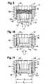
Figs. 1 and 2 . The polyaxial bone screw comprises ascrew element 1 with a threadedshank 2 and ahead 3. Thehead 3 has the shape of a segment of a sphere and comprises at its free end arecess 3 a for engagement with a screw driver. Thescrew element 3 is pivotably held in a receivingpart 4. The receivingpart 4 is substantially cylindrical with afirst end 41 and asecond end 42 and a seat for thehead 3 near thesecond end 42, which will be described later. Acoaxial bore 43 extends from thefirst end 41 to the direction of the second 42. Furthermore, aU-shaped recess 44 is provided at thefirst end 41 by means of which twofree legs internal thread 47 is provided at the inner wall of saidlegs U-shaped recess 44 and thelegs rod 100. Apressure element 5 is provided that is configured to exert pressure onto the head for locking thehead 3 in a particular angular orientation of thescrew element 1 in relation to the receivingpart 4. Thepressure element 5 is substantially cylindrical with afirst end 51 and an oppositesecond end 52, acoaxial bore 53 and aU-shaped recess 54 extending from thefirst end 51 into the direction of thesecond end 52. By means of theU-shaped recess 54 twofree legs rod 100. The height of thelegs rod 100, so that thelegs rod 100 when the rod is inserted. - The bone anchor further includes a locking device comprising a
first locking element 6 and asecond locking element 7. In the assembled state, thesecond locking element 7 is nested within thefirst locking element 6 and is movable between a first position and a second position in an axial direction along a central axis C. - The locking device according to the first embodiment will now be described in more detail with reference to
Figs. 3 to 11 .Figs. 3 to 5 show thefirst locking element 6 before assembly with thesecond locking element 7. Thefirst locking element 6 is substantially cylindrical, and has afirst end 61 and asecond end 62. At least a portion of the outer surface of thefirst locking element 6 comprises anexternal thread 63 that is configured to cooperate with theinternal thread 47 provided on the legs of the receivingpart 4. Thefirst locking element 6 is provided with acoaxial bore 64 with a bore axis C and with aportion 65 comprising an internal thread. Theportion 65 is adjacent or near the second end and extends up to a distance from thefirst end 61. The thread form of theexternal thread 63 is preferably a thread form that prevents splaying of thelegs Figs. 9 to 11 but can also have a flat thread. - The
first locking element 6 further comprises at thesecond end 62 a threadless concavely rounded hollowcylindrical portion 62a that is, after insertion of the second locking element, bent inwards as described below. Adjacent thefirst end 61 the coaxial bore has an inner diameter d1 that is the same or smaller than an inner diameter d2 measured between the crests of the thread of the internally threadedportion 65 but smaller than a diameter d3 between the thread roots of the internally threadedportion 65. By means of this, a stop in form of anabutment 66 is provided for the advancement of thesecond locking element 7 to the direction of thefirst end 61 of thefirst locking element 6. Adjacent thefirst end 61, anengagement structure 67 for engagement with a tool is provided. Theengagement structure 67 can be a plurality of coaxial semi-spherical grooves. - The
second locking element 7 is substantially cylindrical and has afirst end 71 and an oppositesecond end 72. Adjacent thefirst end 71, aportion 73 with an external thread is provided that is configured to cooperate with the internally threadedportion 65 of thefirst locking element 6. Adjacent thesecond end 72, athreadless portion 74 is provided. The outer surface of theportion 74 is substantially smooth. An outer diameter of thethreadless portion 74 is smaller than an outer diameter of the threadedportion 73. Thesecond locking element 7 further comprises a coaxial bore, i.e. arecess 75 and acoaxial recess 76 adjacent thefirst end 71 that has an inner diameter that is greater than that of therecess 75. Furthermore, adjacent thefirst end 71, an engagement structure in the form of a plurality of coaxiallongitudinal grooves 77 is provided that serve for engagement with an insertion and drive tool. The coaxiallongitudinal grooves 77 open into the face of thesecond end 72 formingcircular holes 78 there. Theholes 78 can serve for engagement with a tool to mount the second locking element into the first locking element from thesecond end 62. - The steps of assembling the first and the second locking element will be explained referring to
Figs. 9 to 11 . In a first step, thesecond locking element 7 is introduced into thefirst locking element 6 from thesecond end 62 of thefirst locking element 6. Then, as shown inFig. 10 , thesecond locking element 7 is advanced by screwing it in the direction to thefirst end 61 until itsfirst end 71 abuts against theabutment 66 provided at the coaxial bore of thefirst locking element 6. The length of thesecond locking element 7 in an axial direction is such that when thesecond locking element 7 assumes a first position, wherein itsfirst end 71 abuts against theabutment 66, thesecond end 72 is located within the concavely rounded hollowcylindrical portion 62a. Thereafter, as shown inFig. 11 , the concavely rounded hollowcylindrical portion 62a is bent inwards until it nearly touches thethreadless portion 74 of thesecond locking element 7. By this operation, a second stop in form of anannular abutment 62b is formed. The inner diameter d4 of theannular abutment 62b is smaller than the inner diameter d3 between the roots of the threadedportion 65 of thefirst locking element 6 but greater than an outer diameter of thethreadless portion 74 of thesecond locking element 7. - The parts of the polyaxial bone screw and the locking device are all made from a biocompatible material. Such a biocompatible material can be titanium, stainless steel, biocompatible alloys, such as titanium nickel alloys, for example Nitinol, or can be a biocompatible plastic material, such as PEEK (polyetheretherketone). The components can be made all of the same material or of different materials.
- The function of the locking device is shown in
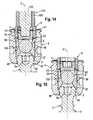
Figs. 12a-13b . InFig. 12a atool 101 is shown that comprises aninner drive portion 102 and anouter drive portion 103. The inner drive portion engages therecess 76 and theengagement structure 77 of the second locking element. Theouter drive portion 103 engages theengagement structure 67 in thefirst locking element 6. Theinner drive portion 102 and theouter drive portion 103 can be rotated independently. By means of theinner drive portion 102, thesecond locking element 7 is rotated so that it is advanced towards thefirst end 61 of thefirst locking element 6 until, as shown inFigs. 12a and 12b , thefirst thread turn 73a adjacent thefirst end 71 of the second locking element abuts against theabutment 66 formed by the inner wall of thecoaxial bore 64. Because the inner diameter d1 of the inner wall of thecoaxial bore 64 is smaller than the inner diameter d3 at the root of theinternal thread 63 of the first locking element, thesecond locking element 7 cannot advance further towards the first end and is at the first end position. When thesecond locking element 7 is in the first end position, agap 104 is present between thefirst end 61 of the first locking element and theouter drive portion 103. - By rotating the
first drive portion 102 and by moving down thesecond drive portion 103 so that it abuts against thefirst end 61 of thefirst locking element 6, thesecond locking element 7 advances in the direction of thesecond end 62 of thefirst locking element 6. The advancement stops, when alast thread turn 73b that is opposite to thefirst thread turn 73a abuts against the second stop in form of theannular abutment 62b. Because the inner diameter d4 of theannular abutment 62b is smaller than the inner diameter d3 between the roots of the threadedportion 63 of thefirst locking element 6, thesecond locking element 7 can not be screwed further towards thesecond end 62 and, therefore, can not escape. When thesecond locking element 7 is in the second end position, thethreadless portion 74 projects out of thesecond end 62 of the first locking element. - The use of the locking device according to the first embodiment is shown in
Figs. 14 and 15. Fig. 14 shows the polyaxial bone screw according toFigs. 1 and 2 in an assembled state. To allow pivoting before fixation, the receivingpart 4 has aseat portion 48, wherein thescrew head 3 is held. The seat portion can be spherically-shaped. The screw head and the threadedshank 2 extend through anopening 49 provided at thesecond end 42 of the receivingpart 4. Thepressure element 5 is arranged on top of thehead 3 and encompasses partially thehead 3 with a spherically-shapedrecess 57. Thepressure element 5 and the receivingpart 4 are aligned such that theU-shaped recesses rod 100. When therod 100 rests in theU-shaped recess 54 of the receivingpart 5, thelegs rod 100. - The locking device is inserted into the receiving part in a pre-assembled manner in which the
second locking element 7 is contained in thefirst locking element 6. With theouter drive portion 103, thefirst locking element 6 is screwed into theinternal thread 47 of the receivingpart 4 until itssecond end 62 abuts against the upper free surface of thelegs first locking element 6, thepressure element 5 exerts pressure onto thehead 3 until thehead 3 is finally locked in a desired angular position of the threadedshank 2 with respect to the central axis C. - The second locking device is advanced by rotating it with the
inner drive portion 102 until thethreadless portion 74 extends out of thefirst locking element 6. Thereby, thesecond end 72 of the second locking element engages the surface of therod 100 and presses therod 100 into theU-shaped recess 54 of thepressure element 5. InFig. 15 , the polyaxial bone screw with the locking device is shown without a tool. Thefirst locking element 6 is screwed into the receiving part and presses onto thefree legs pressure element 5 to lock thehead 3. Thesecond locking element 7 is pressing onto the rod to fix the rod's position in the channel. The rod and the head can be fixed independently from each other, which allows adjustments of the position of the rod while maintaining the angular position of the screw element. - During surgery and before insertion of the locking device, the locking device is taken up by the
tool 101. By an operating error with respect to the tool, it may happen that the second locking element is advanced, even if the locking device is not yet inserted into the receiving part. The first and second stop prevent a backing out or loss of the second locking element from the first locking element. Also, when the locking device has already been inserted into the receiving part, subsequent adjustments that require a loosening of the fixation of the rod, can be safely performed because the second locking element abuts against the first stop when it is screwed back by thefirst drive portion 102. Because thelegs pressure element 5 extend above therod 100, when therod 100 is inserted, thefirst locking element 6 acts only onto thepressure element 5 and therefore only onto thehead 3. Thesecond locking element 7 acts only onto therod 100. - A second embodiment of the locking device is shown in
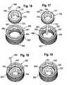
Figs. 16 to 29 . It can be used with the polyaxial bone screw as described before or with any other bone anchor. The locking device comprises afirst locking element 600 and asecond locking element 700. Thefirst locking element 600 and thesecond locking element 700 are connected with the aid of apin 800. The pin is an abutment member that provides for a limitation of the advancement of thesecond locking element 700 in thefirst locking element 600. - Referring first to
Figs. 20 to 22 , thefirst locking element 600 is substantially cylindrical with afirst end 601, asecond end 602, anexternal thread portion 603 and acoaxial bore 604. Adjacent the second end aninternal thread portion 605 is provided. Anengagement structure 607 for engagement with a tool is provided in the region between theinternal thread portion 605 and thefirst end 601. Theengagement structure 607 can comprise coaxially extendingrecesses 607 similar to the first embodiment. - At the transition between the
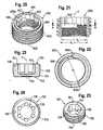
internal thread portion 605 and the portion of thebore 604 that comprises theengagement structure 607, acircumferentially extending groove 606 is provided. Thegroove 606 extends in the circumferential direction slightly more than half a turn or slightly more than a semi-circle, as can be seen best inFig. 22 . The inner diameter d5 of the groove is larger than the inner diameter d6 of theinternal thread portion 605 measured between the roots of theinternal thread portion 605. The height of thegroove 606 in axial direction corresponds to at least one turn of theinternal thread portion 605. By the groove a first stop is provided by the oneend 606c of the groove in a circumferential direction and a second stop is provided by theother end 606d in a circumferential direction of the groove. - The
second locking element 700 has afirst end 701, an oppositesecond end 702 and adjacent thefirst end 701 an externally threadedportion 703. A coaxial bore, i.e.recess 705 extends from the first end in the direction of the second end. Adjacent thesecond end 702, athreadless portion 704 is provided. Adjacent thefirst end 701, acoaxial recess 706 with an engagement structure in the form of, for example, coaxial longitudinal recesses is provided for engagement with a tool. The coaxial engagement recesses 707 extend through thesecond end 702 thereby providingholes 708. As can be seen in particular inFigs. 23 to 25 , arecess 709 is provided for accommodating thepin 800 seen inFigs. 16 to 19 . Thepin 800 is cylindrical and fits into therecess 709 to such an extent that aportion 801 of the pin projects out of therecess 709. The pin may be fixed to the recess. Furthermore, thepin 800 is sized so as to extend into thegroove 606 as shown inFigs. 26 to 29 . Thepin 800 forms an abutment member that is configured to abut against the first stop formed by the oneend 606c of the groove and against the second stop formed by theother end 606d of the groove. - As shown in
Figs. 17 to 19 , the assembly of the locking device according to the second embodiment is carried out by introducing thesecond locking element 700 from the first end of thefirst locking element 600. Once thesecond locking element 700 is nested into thefirst locking element 600 by engagement of the threads, the second locking element is advanced towards the second end until therecess 709 is positioned at one of thecoaxial recesses 707 of the engagement structure that is at a position in the region of thegroove 606. Then, as shown inFig. 18 , thepin 800 is inserted into therecess 709. Thereafter, thesecond locking element 700 can be rotated within the boundaries defined by thegroove 606. - The functioning of the second embodiment of the locking device will be explained with reference to
Figs. 26 to 29 . InFig. 26 , thesecond locking element 700 is in the first position. - The outwardly projecting
portion 801 of thepin 800 abuts against the oneend 606c of thegroove 606. Thesecond end 702 of thesecond locking element 700 does not project out of thefirst locking element 600. In this preassembled state, the locking device can be delivered and used during surgery. - In
Fig. 28 , thesecond locking element 700 has been rotated and advanced downward until the outwardly projectingportion 801 of thepin 800 abuts against the other end 600d of thegroove 600. In this position, thesecond locking element 700 can no longer be advanced downward and therefore is prevented from backing out or escaping out of thefirst locking element 600. The length of thethreadless portion 704 in axial direction is such that in the second position, shown inFig. 28 the portion that projects outward from the first locking element is suitable for pressing onto the rod and fixing the rod. - As in the first embodiment, the external threaded
portion 603 of the first locking element can have any thread form, but preferably has a thread form that prevents splaying of the legs of the receiving part, in particular, a flat thread as shown, or a negative angle thread. Theinternal thread 605 and the cooperating external thread of the second locking element may have a metric thread form or may also have a flat thread form. - The material of the parts and components of the locking device according to the second embodiment are the same or similar to those of the first embodiment.
- The second locking element may be introduced into the first locking element also from the second end. Since the second stop of the locking device is in axial direction approximately in the middle of the first locking element, the locking device according to the second embodiment can be designed more compact.
- In a modification the first locking element 6' comprises an internal flat thread 63' and the second locking element 7' comprises an external flat thread 73' as can be seen from
Figs. 30 to 35b . The thread form is the only difference referring to thefirst locking element 6 and thesecond locking element 7 according to the first embodiment. Figs. 34a and 34b show the second locking element 7' abutting against the abutment 66' with its first end 71'.Fig. 35a and 35b show the second locking element 7' abutting against theannular abutment 62b' with its second end 72'.- Referring to the second embodiment the above mentioned flat thread configuration is also possible.
- One advantage of the flat thread configuration referring to the inner thread of the first locking element 6' and the outer thread of the second locking element 7' is that proper end stops are defined because a flat thread is more robust and does not have sharp edges which could violate the integral structure of these end stops. Because of the robust design of the flat thread smaller dimensioning is possible. This effect will be intensified since no radial forces have to be taken up within the flat thread.
- Further modifications of the embodiments described are conceivable. A locking device can be used also with a monoaxial screw or with a bone plate. For example, the locking device can be used with a monoaxial screw and a rod that is made from an elastomeric material, which is used for dynamic stabilization.
- The second locking element may have at its second end that faces the rod engagement structures such as projections to enhance engagement with the rod.
- The engagement structures in the first and second locking element are not limited to the coaxial grooves. They can have any other shape. Alternatively, an engagement structure at the surface of the first end of the first and/or second locking element may be provided.
- Other constructions of the stops for limiting the movement of the second locking element in the first locking element are conceivable. For example, the first locking element may have an abutment member that abuts in a groove of the second locking element.
- The independent head and rod fixation can be realized by other means. For example, the pressure element can be shaped differently without legs that extend above the rod. In this case, the first locking element may have a structure at its second end that presses onto the pressure element.
- The polyaxial bone anchor can be realized in many different known manners that are configured to engage with the locking device, for example a polyaxial bone anchor with a favored angle bottom configuration or with a bottom loader configuration.
Claims (20)
- A locking device for securing a rod-shaped element in a receiving part of a bone anchor, said locking device comprising:a first locking element (6, 600, 6') having a first end (61, 601) and a second end (62, 602) which is provided with an external thread (63, 603) on at least a portion thereof, a coaxial bore (64, 604) passing entirely through the first locking element the coaxial bore having a bore axis (C) and an internal thread (65, 605) provided in at least a portion of said bore,a second locking element (7, 700, 7'), the second locking element having a first end (71, 701) and a second end (72, 702), an outer surface with an external thread (73, 703) in at least a portion thereof which cooperates with the internal thread provided at said bore of the first locking element,wherein the second locking element (7, 700, 7') is movable along the bore axis (C) by rotating it and wherein a path of advancement of the second locking element is limited towards the first end by a first stop (66, 606c) and towards the second end (62b, 606d) by a second stop and wherein when the second locking element (7, 700, 7') is in a first position defined by the first stop (66, 606c), its first end (71, 701) facing the first end (61, 601) of the first locking element (6, 600) is within the bore.
- The locking device of claim 1, wherein in an assembled state, the first (6, 600) and the second (7, 700) locking element are inseparable.
- The locking device of claims 1 and 2, wherein when the second locking element (7, 700, 7') is in a second position defined by the second stop, at least a portion of the second locking element (74, 704) protrudes outward of the bore.
- The locking device of one of claims 1 to 3, wherein the first locking element (6, 600) has an engagement structure (67, 607) for engagement with a tool provided at the fist end (61, 601) and extending into the bore (64, 604).
- The locking device of one of claims 1 to 4, wherein the first stop (66, 606c) is provided at a distance from the first end (61, 601).
- The locking device of one of claims 1 to 5, wherein the first stop (66, 606c) is an abutment provided at the first locking element (6, 600, 6').
- The locking device of one of claims 1 to 6, wherein the first stop is provided by an inner surface portion (66) of the bore (64), the diameter of which is the same as or smaller than the inner diameter between the crests of the internal thread (65) provided at the first locking element.
- The locking device of one of claims 1 to 7, wherein the second stop (62b) is provided by an abutment at the second end of the first locking element.
- The locking device of one of claims 1 to 8, wherein the second stop is a projection (62b) projecting into the bore further that the root of the internal thread (65).
- The locking device of claim 9, wherein the projection (62b) is annular.
- The locking device of one of claims 1 to 7, wherein the second stop is provided by an abutment (801, 606c, 606d) at a distance from the first end and the second end.
- The locking device of claim 11, wherein the first stop is formed by the first end (606c) of a groove (606) in the inner wall of the bore that faces the first end (601) of the first locking element (600).
- The locking device of claim 11 or 12, wherein the second stop is formed by a second end (606d) of a groove (606) in the inner wall of the bore of the first locking element (600) that faces the second end (602).
- The locking device of one of claims 12 or 13, wherein the second locking element (600) has an abutment member (800, 801) projecting into the groove (606).
- The locking device of one of claims 11 to 14, wherein the abutment member is a pin (800).
- The locking device of one of claims 13 to 15, wherein the groove extends circumferentially, preferably about one half turn or more.
- A bone anchor comprising
an anchoring element (1) comprising a shank (2) to be anchored in a bone or a verterra;
a receiving part (4) connected to the shank (1), the receiving part comprising:a first end (41) opposite to the shank and a second end (42) facing the shank;a longitudinal axis (C) passing through the two ends;a bore (43) coaxial with the longitudinal axis extending from the first end through at least a portion of the receiving part; anda substantially U-shaped recess (44) for receiving a rod-shaped element (100), the recess forming two free legs (45, 46) extending in the direction of the first end (41), the legs being provided with an internal thread (47);and a locking device of one of claims 1 to 16 wherein the external thread (63, 603) of the first locking element is configured to engage the internal thread (47) provided at the legs. - The bone anchor of claim 17, wherein said anchoring element comprises a head (3) and wherein said receiving part (4) comprises a region (41) adjacent to said second end for pivotably receiving said head.
- The bone anchor of claim 18, further comprising a pressure element (5) arranged in the receiving part (4) between the head and the locking device for exerting pressure onto said head to lock the head in the receiving part.
- The bone anchor of claim 18 or 19, wherein said first locking element (6, 600, 6') is configured to lock the head (3) without fixing the rod-shaped element (100) and wherein said second locking element (7, 700, 7') is configured to fix the rod-shaped element.
Priority Applications (10)
| Application Number | Priority Date | Filing Date | Title |
|---|---|---|---|
| ES14169914.0TES2655796T3 (en) | 2011-08-05 | 2011-08-05 | Locking device to block a rod-shaped element in a housing part of a bone anchor and bone anchor with such a locking device |
| EP11176723.2AEP2554130B1 (en) | 2011-08-05 | 2011-08-05 | Locking device for locking a rod-shaped element in a receiving part of a bone anchor and bone anchor with such a locking device |
| EP14169914.0AEP2772216B1 (en) | 2011-08-05 | 2011-08-05 | Locking device for locking a rod-shaped element in a receiving part of a bone anchor and bone anchor with such a locking device |
| ES11176723.2TES2496340T3 (en) | 2011-08-05 | 2011-08-05 | Locking device to block a rod-shaped element in a housing part of a bone anchor and bone anchor with such a locking device |
| KR1020120084606AKR101974928B1 (en) | 2011-08-05 | 2012-08-01 | Locking device for locking a rod-shaped element in a receiving part of a bone anchor and bone anchor with such a locking device |
| TW101127667ATWI587830B (en) | 2011-08-05 | 2012-08-01 | Fixing the rod-shaped member to the locking device for the bone anchor receiving member and the bone anchor thereof |
| JP2012171026AJP5973276B2 (en) | 2011-08-05 | 2012-08-01 | Locking device for locking a rod-like element to a receiving part of a bone fixing device and bone fixing device provided with this locking device |
| US13/564,261US8690925B2 (en) | 2011-08-05 | 2012-08-01 | Locking device for locking a rod-shaped element in a receiving part of a bone anchor and bone anchor with such a locking device |
| CN201210273289.5ACN102908183B (en) | 2011-08-05 | 2012-08-02 | For the locking device that rod-shaped elements is locked in the receiving portion of bone anchor assembly and the bone anchor assembly with such locking device |
| US14/188,465US9271760B2 (en) | 2011-08-05 | 2014-02-24 | Locking device for locking a rod-shaped element in a receiving part of a bone anchor and bone anchor with such a locking device |
Applications Claiming Priority (1)
| Application Number | Priority Date | Filing Date | Title |
|---|---|---|---|
| EP11176723.2AEP2554130B1 (en) | 2011-08-05 | 2011-08-05 | Locking device for locking a rod-shaped element in a receiving part of a bone anchor and bone anchor with such a locking device |
Related Child Applications (1)
| Application Number | Title | Priority Date | Filing Date |
|---|---|---|---|
| EP14169914.0ADivisionEP2772216B1 (en) | 2011-08-05 | 2011-08-05 | Locking device for locking a rod-shaped element in a receiving part of a bone anchor and bone anchor with such a locking device |
Publications (2)
| Publication Number | Publication Date |
|---|---|
| EP2554130A1 EP2554130A1 (en) | 2013-02-06 |
| EP2554130B1true EP2554130B1 (en) | 2014-05-28 |
Family
ID=44510793
Family Applications (2)
| Application Number | Title | Priority Date | Filing Date |
|---|---|---|---|
| EP11176723.2AActiveEP2554130B1 (en) | 2011-08-05 | 2011-08-05 | Locking device for locking a rod-shaped element in a receiving part of a bone anchor and bone anchor with such a locking device |
| EP14169914.0AActiveEP2772216B1 (en) | 2011-08-05 | 2011-08-05 | Locking device for locking a rod-shaped element in a receiving part of a bone anchor and bone anchor with such a locking device |
Family Applications After (1)
| Application Number | Title | Priority Date | Filing Date |
|---|---|---|---|
| EP14169914.0AActiveEP2772216B1 (en) | 2011-08-05 | 2011-08-05 | Locking device for locking a rod-shaped element in a receiving part of a bone anchor and bone anchor with such a locking device |
Country Status (7)
| Country | Link |
|---|---|
| US (2) | US8690925B2 (en) |
| EP (2) | EP2554130B1 (en) |
| JP (1) | JP5973276B2 (en) |
| KR (1) | KR101974928B1 (en) |
| CN (1) | CN102908183B (en) |
| ES (2) | ES2655796T3 (en) |
| TW (1) | TWI587830B (en) |
Families Citing this family (21)
| Publication number | Priority date | Publication date | Assignee | Title |
|---|---|---|---|---|
| US8007522B2 (en) | 2008-02-04 | 2011-08-30 | Depuy Spine, Inc. | Methods for correction of spinal deformities |
| US20140018867A1 (en)* | 2011-02-04 | 2014-01-16 | Stefan Freudiger | Precaution against jamming on open bone screws |
| US9655655B2 (en)* | 2011-08-16 | 2017-05-23 | Aesculap Implant Systems, Llc | Two step locking screw assembly |
| ES2549634T3 (en)* | 2012-05-31 | 2015-10-30 | Biedermann Technologies Gmbh & Co. Kg | Polyaxial bone anchoring device |
| US9782204B2 (en) | 2012-09-28 | 2017-10-10 | Medos International Sarl | Bone anchor assemblies |
| US9775660B2 (en) | 2013-03-14 | 2017-10-03 | DePuy Synthes Products, Inc. | Bottom-loading bone anchor assemblies and methods |
| US20140277153A1 (en) | 2013-03-14 | 2014-09-18 | DePuy Synthes Products, LLC | Bone Anchor Assemblies and Methods With Improved Locking |
| US10342582B2 (en) | 2013-03-14 | 2019-07-09 | DePuy Synthes Products, Inc. | Bone anchor assemblies and methods with improved locking |
| US9259247B2 (en) | 2013-03-14 | 2016-02-16 | Medos International Sarl | Locking compression members for use with bone anchor assemblies and methods |
| US9724145B2 (en) | 2013-03-14 | 2017-08-08 | Medos International Sarl | Bone anchor assemblies with multiple component bottom loading bone anchors |
| CN106796335B (en)* | 2014-07-25 | 2019-07-09 | 国家光学研究所 | Optical components mounted with tilt control of optics in the lens barrel |
| US9968378B1 (en)* | 2015-07-22 | 2018-05-15 | University Of South Florida | Adaptation sphere saddle |
| US10610265B1 (en) | 2017-07-31 | 2020-04-07 | K2M, Inc. | Polyaxial bone screw with increased angulation |
| EP3695796B1 (en)* | 2019-02-13 | 2022-08-03 | Biedermann Technologies GmbH & Co. KG | Anchoring assembly for anchoring a rod to a bone or a vertebra |
| EP3730078B1 (en)* | 2019-04-26 | 2021-06-09 | Biedermann Technologies GmbH & Co. KG | Closure assembly for securing a stabilization element in a receiving part of a bone anchoring device |
| US11571244B2 (en) | 2019-05-22 | 2023-02-07 | Nuvasive, Inc. | Posterior spinal fixation screws |
| DE212021000375U1 (en)* | 2020-05-08 | 2023-03-01 | Lifespans Limited | Bone fixation system and elements thereof |
| US11627992B2 (en) | 2020-12-21 | 2023-04-18 | Warsaw Orthopedic, Inc. | Locking-cap module and connector |
| US11627995B2 (en)* | 2020-12-21 | 2023-04-18 | Warsaw Orthopedic, Inc. | Locking-cap module and connector |
| WO2022184797A1 (en) | 2021-03-05 | 2022-09-09 | Medos International Sarl | Selectively locking polyaxial screw |
| US11957391B2 (en) | 2021-11-01 | 2024-04-16 | Warsaw Orthopedic, Inc. | Bone screw having an overmold of a shank |
Family Cites Families (15)
| Publication number | Priority date | Publication date | Assignee | Title |
|---|---|---|---|---|
| DE10157969C1 (en) | 2001-11-27 | 2003-02-06 | Biedermann Motech Gmbh | Element used in spinal and accident surgery comprises a shaft joined to a holding element having a U-shaped recess with two free arms having an internal thread with flanks lying at right angles to the central axis of the holding element |
| DE10157814B4 (en) | 2001-11-27 | 2004-12-02 | Biedermann Motech Gmbh | Closure device for securing a rod-shaped element in a holding element connected to a shaft |
| FR2832620B1 (en) | 2001-11-27 | 2004-01-23 | Eurosurgical | CONNECTOR FOR VERTEBRAL ANCHORAGE SYSTEM |
| DE10164323C1 (en) | 2001-12-28 | 2003-06-18 | Biedermann Motech Gmbh | Bone screw has holder element joined to shaft and possessing two free arms , with inner screw, slot, external nut, cavity and shoulder cooperating with attachment |
| US20040158247A1 (en) | 2003-02-07 | 2004-08-12 | Arthit Sitiso | Polyaxial pedicle screw system |
| US7776067B2 (en)* | 2005-05-27 | 2010-08-17 | Jackson Roger P | Polyaxial bone screw with shank articulation pressure insert and method |
| US7204838B2 (en) | 2004-12-20 | 2007-04-17 | Jackson Roger P | Medical implant fastener with nested set screw and method |
| US7789896B2 (en)* | 2005-02-22 | 2010-09-07 | Jackson Roger P | Polyaxial bone screw assembly |
| US8100946B2 (en) | 2005-11-21 | 2012-01-24 | Synthes Usa, Llc | Polyaxial bone anchors with increased angulation |
| WO2007075454A1 (en)* | 2005-12-19 | 2007-07-05 | Synthes (U.S.A) | Polyaxial bone anchor with headless pedicle screw |
| ES2395948T3 (en) | 2006-12-22 | 2013-02-18 | Biedermann Technologies Gmbh & Co. Kg | Bone anchoring device |
| DE202007012643U1 (en)* | 2007-08-30 | 2007-11-08 | Aesculap Ag & Co. Kg | Orthopedic retention system |
| DE102007042953B4 (en) | 2007-08-30 | 2015-01-22 | Aesculap Ag | Orthopedic retention system |
| ES2375526T3 (en) | 2008-06-19 | 2012-03-01 | Biedermann Motech Gmbh | BONE ANCHORAGE ASSEMBLY. |
| EP2160988B1 (en)* | 2008-09-04 | 2012-12-26 | Biedermann Technologies GmbH & Co. KG | Rod-shaped implant in particular for stabilizing the spinal column and stabilization device including such a rod-shaped implant |
- 2011
- 2011-08-05EPEP11176723.2Apatent/EP2554130B1/enactiveActive
- 2011-08-05ESES14169914.0Tpatent/ES2655796T3/enactiveActive
- 2011-08-05ESES11176723.2Tpatent/ES2496340T3/enactiveActive
- 2011-08-05EPEP14169914.0Apatent/EP2772216B1/enactiveActive
- 2012
- 2012-08-01KRKR1020120084606Apatent/KR101974928B1/enactiveActive
- 2012-08-01USUS13/564,261patent/US8690925B2/enactiveActive
- 2012-08-01JPJP2012171026Apatent/JP5973276B2/enactiveActive
- 2012-08-01TWTW101127667Apatent/TWI587830B/ennot_activeIP Right Cessation
- 2012-08-02CNCN201210273289.5Apatent/CN102908183B/enactiveActive
- 2014
- 2014-02-24USUS14/188,465patent/US9271760B2/enactiveActive
Also Published As
| Publication number | Publication date |
|---|---|
| KR20130016096A (en) | 2013-02-14 |
| EP2772216A1 (en) | 2014-09-03 |
| CN102908183B (en) | 2016-12-21 |
| JP2013034866A (en) | 2013-02-21 |
| TWI587830B (en) | 2017-06-21 |
| US20140303673A1 (en) | 2014-10-09 |
| CN102908183A (en) | 2013-02-06 |
| ES2655796T3 (en) | 2018-02-21 |
| TW201306791A (en) | 2013-02-16 |
| JP5973276B2 (en) | 2016-08-23 |
| EP2772216B1 (en) | 2017-11-08 |
| US20130103093A1 (en) | 2013-04-25 |
| ES2496340T3 (en) | 2014-09-18 |
| US9271760B2 (en) | 2016-03-01 |
| US8690925B2 (en) | 2014-04-08 |
| KR101974928B1 (en) | 2019-05-03 |
| EP2554130A1 (en) | 2013-02-06 |
Similar Documents
| Publication | Publication Date | Title |
|---|---|---|
| EP2554130B1 (en) | Locking device for locking a rod-shaped element in a receiving part of a bone anchor and bone anchor with such a locking device | |
| EP2371311B1 (en) | Bone anchoring device | |
| EP2586392B1 (en) | High angulation polyaxial bone anchoring device | |
| EP2837347B1 (en) | Bone anchoring device | |
| EP2455028B1 (en) | Polyaxial bone anchoring device | |
| EP2468198B1 (en) | Bone anchoring device | |
| JP6139988B2 (en) | Polyaxial bone anchoring device | |
| EP2985001B1 (en) | Polyaxial bone anchoring device | |
| EP2764840B1 (en) | Coupling assembly for coupling a rod to a bone anchoring element and bone anchoring device with such a coupling assembly | |
| EP2570090B1 (en) | Polyaxial bone anchoring device with enlarged pivot angle | |
| EP2586391B1 (en) | A locking assembly for a polyaxial bone anchoring device | |
| EP2559391A1 (en) | Polyaxial bone anchoring system | |
| EP2881053A1 (en) | Extension device for a bone anchor, in particular for minimally invasive surgery | |
| US11147593B2 (en) | Bone anchoring device | |
| KR20130035915A (en) | Bone anchoring device and tool cooperating with such a bone anchoring device | |
| US20130345758A1 (en) | Polyaxial bone anchoring device | |
| CN114052879A (en) | Bone Anchoring Device |
Legal Events
| Date | Code | Title | Description |
|---|---|---|---|
| PUAI | Public reference made under article 153(3) epc to a published international application that has entered the european phase | Free format text:ORIGINAL CODE: 0009012 | |
| AK | Designated contracting states | Kind code of ref document:A1 Designated state(s):AL AT BE BG CH CY CZ DE DK EE ES FI FR GB GR HR HU IE IS IT LI LT LU LV MC MK MT NL NO PL PT RO RS SE SI SK SM TR | |
| AX | Request for extension of the european patent | Extension state:BA ME | |
| 17P | Request for examination filed | Effective date:20130806 | |
| RBV | Designated contracting states (corrected) | Designated state(s):AL AT BE BG CH CY CZ DE DK EE ES FI FR GB GR HR HU IE IS IT LI LT LU LV MC MK MT NL NO PL PT RO RS SE SI SK SM TR | |
| RIC1 | Information provided on ipc code assigned before grant | Ipc:A61B 17/86 20060101ALI20131025BHEP Ipc:A61B 17/70 20060101AFI20131025BHEP | |
| GRAP | Despatch of communication of intention to grant a patent | Free format text:ORIGINAL CODE: EPIDOSNIGR1 | |
| INTG | Intention to grant announced | Effective date:20140106 | |
| GRAS | Grant fee paid | Free format text:ORIGINAL CODE: EPIDOSNIGR3 | |
| GRAA | (expected) grant | Free format text:ORIGINAL CODE: 0009210 | |
| AK | Designated contracting states | Kind code of ref document:B1 Designated state(s):AL AT BE BG CH CY CZ DE DK EE ES FI FR GB GR HR HU IE IS IT LI LT LU LV MC MK MT NL NO PL PT RO RS SE SI SK SM TR | |
| REG | Reference to a national code | Ref country code:GB Ref legal event code:FG4D | |
| REG | Reference to a national code | Ref country code:CH Ref legal event code:EP Ref country code:CH Ref legal event code:NV Representative=s name:NOVAGRAAF INTERNATIONAL SA, CH | |
| REG | Reference to a national code | Ref country code:AT Ref legal event code:REF Ref document number:670173 Country of ref document:AT Kind code of ref document:T Effective date:20140615 | |
| REG | Reference to a national code | Ref country code:IE Ref legal event code:FG4D | |
| REG | Reference to a national code | Ref country code:DE Ref legal event code:R096 Ref document number:602011007286 Country of ref document:DE Effective date:20140710 | |
| REG | Reference to a national code | Ref country code:ES Ref legal event code:FG2A Ref document number:2496340 Country of ref document:ES Kind code of ref document:T3 Effective date:20140918 | |
| REG | Reference to a national code | Ref country code:AT Ref legal event code:MK05 Ref document number:670173 Country of ref document:AT Kind code of ref document:T Effective date:20140528 | |
| REG | Reference to a national code | Ref country code:NL Ref legal event code:VDEP Effective date:20140528 | |
| REG | Reference to a national code | Ref country code:LT Ref legal event code:MG4D | |
| PG25 | Lapsed in a contracting state [announced via postgrant information from national office to epo] | Ref country code:CY Free format text:LAPSE BECAUSE OF FAILURE TO SUBMIT A TRANSLATION OF THE DESCRIPTION OR TO PAY THE FEE WITHIN THE PRESCRIBED TIME-LIMIT Effective date:20140528 Ref country code:FI Free format text:LAPSE BECAUSE OF FAILURE TO SUBMIT A TRANSLATION OF THE DESCRIPTION OR TO PAY THE FEE WITHIN THE PRESCRIBED TIME-LIMIT Effective date:20140528 Ref country code:IS Free format text:LAPSE BECAUSE OF FAILURE TO SUBMIT A TRANSLATION OF THE DESCRIPTION OR TO PAY THE FEE WITHIN THE PRESCRIBED TIME-LIMIT Effective date:20140928 Ref country code:GR Free format text:LAPSE BECAUSE OF FAILURE TO SUBMIT A TRANSLATION OF THE DESCRIPTION OR TO PAY THE FEE WITHIN THE PRESCRIBED TIME-LIMIT Effective date:20140829 Ref country code:NO Free format text:LAPSE BECAUSE OF FAILURE TO SUBMIT A TRANSLATION OF THE DESCRIPTION OR TO PAY THE FEE WITHIN THE PRESCRIBED TIME-LIMIT Effective date:20140828 Ref country code:LT Free format text:LAPSE BECAUSE OF FAILURE TO SUBMIT A TRANSLATION OF THE DESCRIPTION OR TO PAY THE FEE WITHIN THE PRESCRIBED TIME-LIMIT Effective date:20140528 | |
| PG25 | Lapsed in a contracting state [announced via postgrant information from national office to epo] | Ref country code:SE Free format text:LAPSE BECAUSE OF FAILURE TO SUBMIT A TRANSLATION OF THE DESCRIPTION OR TO PAY THE FEE WITHIN THE PRESCRIBED TIME-LIMIT Effective date:20140528 Ref country code:RS Free format text:LAPSE BECAUSE OF FAILURE TO SUBMIT A TRANSLATION OF THE DESCRIPTION OR TO PAY THE FEE WITHIN THE PRESCRIBED TIME-LIMIT Effective date:20140528 Ref country code:AT Free format text:LAPSE BECAUSE OF FAILURE TO SUBMIT A TRANSLATION OF THE DESCRIPTION OR TO PAY THE FEE WITHIN THE PRESCRIBED TIME-LIMIT Effective date:20140528 Ref country code:HR Free format text:LAPSE BECAUSE OF FAILURE TO SUBMIT A TRANSLATION OF THE DESCRIPTION OR TO PAY THE FEE WITHIN THE PRESCRIBED TIME-LIMIT Effective date:20140528 Ref country code:LV Free format text:LAPSE BECAUSE OF FAILURE TO SUBMIT A TRANSLATION OF THE DESCRIPTION OR TO PAY THE FEE WITHIN THE PRESCRIBED TIME-LIMIT Effective date:20140528 | |
| PG25 | Lapsed in a contracting state [announced via postgrant information from national office to epo] | Ref country code:PT Free format text:LAPSE BECAUSE OF FAILURE TO SUBMIT A TRANSLATION OF THE DESCRIPTION OR TO PAY THE FEE WITHIN THE PRESCRIBED TIME-LIMIT Effective date:20140929 | |
| PG25 | Lapsed in a contracting state [announced via postgrant information from national office to epo] | Ref country code:BE Free format text:LAPSE BECAUSE OF FAILURE TO SUBMIT A TRANSLATION OF THE DESCRIPTION OR TO PAY THE FEE WITHIN THE PRESCRIBED TIME-LIMIT Effective date:20140528 Ref country code:CZ Free format text:LAPSE BECAUSE OF FAILURE TO SUBMIT A TRANSLATION OF THE DESCRIPTION OR TO PAY THE FEE WITHIN THE PRESCRIBED TIME-LIMIT Effective date:20140528 Ref country code:EE Free format text:LAPSE BECAUSE OF FAILURE TO SUBMIT A TRANSLATION OF THE DESCRIPTION OR TO PAY THE FEE WITHIN THE PRESCRIBED TIME-LIMIT Effective date:20140528 Ref country code:SK Free format text:LAPSE BECAUSE OF FAILURE TO SUBMIT A TRANSLATION OF THE DESCRIPTION OR TO PAY THE FEE WITHIN THE PRESCRIBED TIME-LIMIT Effective date:20140528 Ref country code:RO Free format text:LAPSE BECAUSE OF FAILURE TO SUBMIT A TRANSLATION OF THE DESCRIPTION OR TO PAY THE FEE WITHIN THE PRESCRIBED TIME-LIMIT Effective date:20140528 Ref country code:DK Free format text:LAPSE BECAUSE OF FAILURE TO SUBMIT A TRANSLATION OF THE DESCRIPTION OR TO PAY THE FEE WITHIN THE PRESCRIBED TIME-LIMIT Effective date:20140528 | |
| PG25 | Lapsed in a contracting state [announced via postgrant information from national office to epo] | Ref country code:PL Free format text:LAPSE BECAUSE OF FAILURE TO SUBMIT A TRANSLATION OF THE DESCRIPTION OR TO PAY THE FEE WITHIN THE PRESCRIBED TIME-LIMIT Effective date:20140528 Ref country code:NL Free format text:LAPSE BECAUSE OF FAILURE TO SUBMIT A TRANSLATION OF THE DESCRIPTION OR TO PAY THE FEE WITHIN THE PRESCRIBED TIME-LIMIT Effective date:20140528 | |
| REG | Reference to a national code | Ref country code:DE Ref legal event code:R097 Ref document number:602011007286 Country of ref document:DE | |
| PG25 | Lapsed in a contracting state [announced via postgrant information from national office to epo] | Ref country code:MC Free format text:LAPSE BECAUSE OF FAILURE TO SUBMIT A TRANSLATION OF THE DESCRIPTION OR TO PAY THE FEE WITHIN THE PRESCRIBED TIME-LIMIT Effective date:20140528 Ref country code:LU Free format text:LAPSE BECAUSE OF FAILURE TO SUBMIT A TRANSLATION OF THE DESCRIPTION OR TO PAY THE FEE WITHIN THE PRESCRIBED TIME-LIMIT Effective date:20140805 | |
| PLBE | No opposition filed within time limit | Free format text:ORIGINAL CODE: 0009261 | |
| STAA | Information on the status of an ep patent application or granted ep patent | Free format text:STATUS: NO OPPOSITION FILED WITHIN TIME LIMIT | |
| PG25 | Lapsed in a contracting state [announced via postgrant information from national office to epo] | Ref country code:BE Free format text:LAPSE BECAUSE OF FAILURE TO SUBMIT A TRANSLATION OF THE DESCRIPTION OR TO PAY THE FEE WITHIN THE PRESCRIBED TIME-LIMIT Effective date:20140831 | |
| 26N | No opposition filed | Effective date:20150303 | |
| REG | Reference to a national code | Ref country code:IE Ref legal event code:MM4A | |
| REG | Reference to a national code | Ref country code:DE Ref legal event code:R097 Ref document number:602011007286 Country of ref document:DE Effective date:20150303 | |
| PG25 | Lapsed in a contracting state [announced via postgrant information from national office to epo] | Ref country code:SI Free format text:LAPSE BECAUSE OF FAILURE TO SUBMIT A TRANSLATION OF THE DESCRIPTION OR TO PAY THE FEE WITHIN THE PRESCRIBED TIME-LIMIT Effective date:20140528 | |
| PG25 | Lapsed in a contracting state [announced via postgrant information from national office to epo] | Ref country code:IE Free format text:LAPSE BECAUSE OF NON-PAYMENT OF DUE FEES Effective date:20140805 | |
| PG25 | Lapsed in a contracting state [announced via postgrant information from national office to epo] | Ref country code:SM Free format text:LAPSE BECAUSE OF FAILURE TO SUBMIT A TRANSLATION OF THE DESCRIPTION OR TO PAY THE FEE WITHIN THE PRESCRIBED TIME-LIMIT Effective date:20140528 | |
| PG25 | Lapsed in a contracting state [announced via postgrant information from national office to epo] | Ref country code:BG Free format text:LAPSE BECAUSE OF FAILURE TO SUBMIT A TRANSLATION OF THE DESCRIPTION OR TO PAY THE FEE WITHIN THE PRESCRIBED TIME-LIMIT Effective date:20140528 Ref country code:MT Free format text:LAPSE BECAUSE OF FAILURE TO SUBMIT A TRANSLATION OF THE DESCRIPTION OR TO PAY THE FEE WITHIN THE PRESCRIBED TIME-LIMIT Effective date:20140528 | |
| PG25 | Lapsed in a contracting state [announced via postgrant information from national office to epo] | Ref country code:HU Free format text:LAPSE BECAUSE OF FAILURE TO SUBMIT A TRANSLATION OF THE DESCRIPTION OR TO PAY THE FEE WITHIN THE PRESCRIBED TIME-LIMIT; INVALID AB INITIO Effective date:20110805 Ref country code:TR Free format text:LAPSE BECAUSE OF FAILURE TO SUBMIT A TRANSLATION OF THE DESCRIPTION OR TO PAY THE FEE WITHIN THE PRESCRIBED TIME-LIMIT Effective date:20140528 | |
| REG | Reference to a national code | Ref country code:FR Ref legal event code:PLFP Year of fee payment:6 | |
| REG | Reference to a national code | Ref country code:FR Ref legal event code:PLFP Year of fee payment:7 | |
| PG25 | Lapsed in a contracting state [announced via postgrant information from national office to epo] | Ref country code:MK Free format text:LAPSE BECAUSE OF FAILURE TO SUBMIT A TRANSLATION OF THE DESCRIPTION OR TO PAY THE FEE WITHIN THE PRESCRIBED TIME-LIMIT Effective date:20140528 | |
| REG | Reference to a national code | Ref country code:FR Ref legal event code:PLFP Year of fee payment:8 | |
| PG25 | Lapsed in a contracting state [announced via postgrant information from national office to epo] | Ref country code:AL Free format text:LAPSE BECAUSE OF FAILURE TO SUBMIT A TRANSLATION OF THE DESCRIPTION OR TO PAY THE FEE WITHIN THE PRESCRIBED TIME-LIMIT Effective date:20140528 | |
| P01 | Opt-out of the competence of the unified patent court (upc) registered | Effective date:20230526 | |
| PGFP | Annual fee paid to national office [announced via postgrant information from national office to epo] | Ref country code:DE Payment date:20240827 Year of fee payment:14 | |
| PGFP | Annual fee paid to national office [announced via postgrant information from national office to epo] | Ref country code:GB Payment date:20240821 Year of fee payment:14 | |
| PGFP | Annual fee paid to national office [announced via postgrant information from national office to epo] | Ref country code:FR Payment date:20240823 Year of fee payment:14 | |
| PGFP | Annual fee paid to national office [announced via postgrant information from national office to epo] | Ref country code:CH Payment date:20240901 Year of fee payment:14 | |
| PGFP | Annual fee paid to national office [announced via postgrant information from national office to epo] | Ref country code:IT Payment date:20240827 Year of fee payment:14 | |
| PGFP | Annual fee paid to national office [announced via postgrant information from national office to epo] | Ref country code:ES Payment date:20250905 Year of fee payment:15 |