EP2550936B1 - Oral hygiene implement and oral hygiene device - Google Patents
Oral hygiene implement and oral hygiene deviceDownload PDFInfo
- Publication number
- EP2550936B1 EP2550936B1EP20110006101EP11006101AEP2550936B1EP 2550936 B1EP2550936 B1EP 2550936B1EP 20110006101EP20110006101EP 20110006101EP 11006101 AEP11006101 AEP 11006101AEP 2550936 B1EP2550936 B1EP 2550936B1
- Authority
- EP
- European Patent Office
- Prior art keywords
- oral hygiene
- hygiene implement
- accordance
- housing
- axle
- Prior art date
- Legal status (The legal status is an assumption and is not a legal conclusion. Google has not performed a legal analysis and makes no representation as to the accuracy of the status listed.)
- Active
Links
Images


Classifications
- A—HUMAN NECESSITIES
- A61—MEDICAL OR VETERINARY SCIENCE; HYGIENE
- A61C—DENTISTRY; APPARATUS OR METHODS FOR ORAL OR DENTAL HYGIENE
- A61C17/00—Devices for cleaning, polishing, rinsing or drying teeth, teeth cavities or prostheses; Saliva removers; Dental appliances for receiving spittle
- A61C17/16—Power-driven cleaning or polishing devices
- A61C17/22—Power-driven cleaning or polishing devices with brushes, cushions, cups, or the like
- A61C17/32—Power-driven cleaning or polishing devices with brushes, cushions, cups, or the like reciprocating or oscillating
- A61C17/34—Power-driven cleaning or polishing devices with brushes, cushions, cups, or the like reciprocating or oscillating driven by electric motor
- A61C17/3409—Power-driven cleaning or polishing devices with brushes, cushions, cups, or the like reciprocating or oscillating driven by electric motor characterized by the movement of the brush body
- A61C17/3436—Rotation around the axis perpendicular to the plane defined by the bristle holder
- A—HUMAN NECESSITIES
- A61—MEDICAL OR VETERINARY SCIENCE; HYGIENE
- A61C—DENTISTRY; APPARATUS OR METHODS FOR ORAL OR DENTAL HYGIENE
- A61C17/00—Devices for cleaning, polishing, rinsing or drying teeth, teeth cavities or prostheses; Saliva removers; Dental appliances for receiving spittle
- A61C17/16—Power-driven cleaning or polishing devices
- A61C17/22—Power-driven cleaning or polishing devices with brushes, cushions, cups, or the like
- A61C17/222—Brush body details, e.g. the shape thereof or connection to handle
- A—HUMAN NECESSITIES
- A61—MEDICAL OR VETERINARY SCIENCE; HYGIENE
- A61C—DENTISTRY; APPARATUS OR METHODS FOR ORAL OR DENTAL HYGIENE
- A61C17/00—Devices for cleaning, polishing, rinsing or drying teeth, teeth cavities or prostheses; Saliva removers; Dental appliances for receiving spittle
- A61C17/16—Power-driven cleaning or polishing devices
- A61C17/22—Power-driven cleaning or polishing devices with brushes, cushions, cups, or the like
- A61C17/24—Power-driven cleaning or polishing devices with brushes, cushions, cups, or the like rotating continuously
- A61C17/26—Power-driven cleaning or polishing devices with brushes, cushions, cups, or the like rotating continuously driven by electric motor
Definitions
- the present inventionis concerned with an oral hygiene implement and with an oral hygiene device. It is in particular concerned with an oral hygiene implement having a movably mounted functional element that is locked at the housing by a fixation element.
- the movably mounted brush headmay be locked at the housing of the refill by means of a locking pin.
- the locking pinextends into a recess in the functional element and thus inhibits the functional element from being easily separated from the housing without irreparable damage to at least the housing or the functional element, see for example US-A-2001/014 990 .
- an oral hygiene devicecomprising a handle and an oral hygiene implement as proposed that is detachably attached to the handle.
- An oral hygiene implementcomprises a fixation element for locking a movably mounted functional element with respect to the housing so that the functional element cannot be separated from the housing with incurring irreparable damage to oral hygiene implement.
- the fixation elementextends through a recess or cut-out (e.g. a through hole) provided in the functional element, where the recess or cut-out may in particular be provided in a carrier element of the functional element.
- the fixation elementis arranged such that a rotation axis of the functional element extends through the fixation element, in particular wherein an axle extending along the rotation axis is born by the fixation element, where the axle may be fixedly secured at the fixation element or the axle may be floatingly supported by the fixation element such that at least a rotation of the axle around the rotation axis is enabled.
- the fixation elementis secured at least at two different locations at the housing, optionally where these locations are essentially oppositely arranged at the housing.
- the fixation elementis non-detachably secured at the housing of the oral hygiene implement.
- the fixation elementextends in a curved manner between two mounting locations.
- the fixation elementis secured at an inwardly thickened portion of the housing of the oral hygiene implement.
- Fig. 1is a perspective depiction of an example embodiment of an oral hygiene device 1.
- the oral hygiene device 1may be realized as an electric toothbrush.
- the oral hygiene devicecomprises an oral hygiene implement 10 and a handle 20.
- the oral hygiene implement 10may be realized as a brush section of the electric toothbrush.
- the oral hygiene implement 10may in particular be realized as a detachable attachment for simple replacement with other oral hygiene implements, e.g. when the oral hygiene implement 10 is worn out or in case that a different oral hygiene treatment should be performed.
- the oral hygiene implement 10has a functional element 200 that is movably mounted at a housing 290 of the oral hygiene implement 10.
- the functional element 200is here realized as a brush head having cleaning elements for cleaning teeth and/or massaging gums.
- Fig. 2is a depiction of an example embodiment of an oral hygiene implement 10 in accordance with at least one aspect of the present disclosure.
- the oral hygiene implement 10may be realized as a detachable attachment.
- the oral hygiene implement 10has a movably mounted functional element 200, which may be realized as a brush head having cleaning elements 280 for cleaning teeth and/or massaging gums.
- the housing 290 of the oral hygiene implement 10may have an elongated, essentially tubular form that tapers slightly towards the head region.
- the oral hygiene implement 10may generally be structured so that it can be entered into the oral cavity while keeping discomfort at a low level and to allow for cleaning of the teeth such as the molars.
- the oral hygiene implement 10may have a longitudinal extension axis L and the functional element 200 may be mounted for rotation or oscillatory rotation around a rotation axis R (shown in Figure 3 ) that may be essentially perpendicular to the longitudinal extension axis L (while this shall not be interpreted as limiting the possible embodiments of oral hygiene implements in accordance with at least one aspect of the present disclosure).
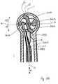
- Fig. 3is a cross sectional cut through a head region of an example embodiment of an oral hygiene implement, which cross sectional cut is taken such that a rotation axis R lies in the cut plane.
- a functional element 200Ais here shown without cleaning elements as shown in e.g. Fig. 2 for simplification of the visualization.
- the functional element 200Ais movably mounted at the housing 290A of the oral hygiene implement such that it can rotate or oscillate around the rotation axis R.
- the functional element 200Acomprises a carrier element 210A.
- the carrier element 210Ahas a cut-out (e.g. a through-hole) or recess 216A through which the rotation axis R extends and through which a fixation element 230A extends.
- the fixation element 230Ahas a bore 231A in which an axle 240A that extends along the rotation axis R is supported. In one embodiment, the axle 240A may be press-fitted into the bore 231A.
- the fixation element 230Amay be elongated and may extend in a direction essentially perpendicular to the rotation axis R through the cut-out or recess 216A.
- Two ends 235A and 236A of the fixation element 230A that may lie oppositely to each other in the elongated extension directionmay be realized as snap-noses that are snapped into respective cut-outs 291A and 292A in the housing 290A of the oral hygiene implement.
- the snap connectionmay be realized as being non-detachable, i.e. the mounted fixation element 230A then essentially cannot be separated from the oral hygiene implement without any irreversible damages to the oral hygiene implement (i.e. at least one of the housing 290A, the fixation element 230A, or the functional element 200A will suffer irreversible damage).
- the snap-noses of the fixation element 230Amay have 90 degree undercuts that extend into the cut-outs 291A and 292A provided in the housing 290A and thus avoid that the fixation element 230A can be easily separated from the housing 290A when mounted.
- the fixation elementmay be glued to the housing, may be screwed to the housing, may be welded to the housing, etc., i.e. the fixation element may be fixedly secured to the housing.
- the fixation elementmay be detachably secured at the housing, where the threshold force to detach the fixation element from the housing is chosen so high that such force levels would not occur during regular use of the oral hygiene implement.
- the carrier element 210Amay have a front carrier element 211A in which mounting holes 281A for mounting cleaning elements may be provided.
- the cleaning elementsmay be realized as bristle tufts that may be mounted by anchor tufting technology. In other embodiments, the cleaning elements may be realized as soft elastomeric elements, as movably mounted plastic elements etc. or as a mixture of different cleaning elements.
- the carrier elementmay not be provided with any mounting holes but the carrier element may be provided with cleaning structures such as tongue cleaning structures.
- the carrier element 210Ahas further a rear carrier element 219A.
- the front carrier element 211A and the rear carrier element 219Aare connected via a connector carrier element 215A.
- the front carrier element 211A, the connector carrier element 215A, and the rear carrier element 219Amay be realized as an integral element such as a plastic injection molded element, which shall not exclude that in other embodiments, that at least two of the three parts of the carrier element 210A are non-detachably snapped together or are screwed together or are glued together etc.
- the front carrier element 211A and the rear carrier element 219Aare arranged such that the rotation axis R extends through the front carrier element 211A and the rear carrier element 219A, while the connector carrier element 215A is arranged such that the rotation axis R extends through the cut-out or recess 216A provided in the carrier element 210A and does not intersect the connector carrier element 215A.
- the fixation element 230Aextends through the cut-out or recess 216A such that the rotation axis R extends through the fixation element 230A.
- the front carrier element 211Ahas a blind hole 212A and the rear carrier 219A has a bore 218A that both extend along the rotation axis R and that both accommodate the axle 240A.
- the axle 240Ain which the axle 240A is press-fitted into the bore 231A in the fixation element 230A and is as such fixed, the axle 240A may be loosely born in the blind hole 212A and the bore 218A (i.e. the blind hole 212A and the bore 218A form floating bearings of the axle 240A).
- the housing 290Amay have a blind-hole 293A that extends along the rotation axis R and that accommodates the axle 240A.
- the axle 240Amay be press-fitted into the blind-hole 293A.
- the axle 240Amay be fixedly secured at the carrier element 210A, e.g. the axle 240A may then be press-fitted into the blind-hole 212A and the bore 218A and may be loosely born in the blind-hole 293A and the bore 231A.
- the axle 240Amay be supported (in some embodiments pivot-mounted) at two locations at the carrier element 210A, which locations have a relatively large distance between each other. In particular, the two locations are arranged oppositely to each other with respect to the fixation element. This likely leads to a reduction of wobbling the carrier element 210A may experience during operation (i.e. when the carrier element 210A rotates or oscillates around the rotation axis R) in comparison to embodiments in which the axle would only be born at a single location. This becomes in particular relevant when the functional element is driven into a high rotation speed or a high frequency oscillation (e.g.
- the fixation element 230Alocks the carrier element 210A with respect to the housing 290A. It is very likely that only strong forces that would typically not be applied at the carrier element 210A during a typical oral hygiene operation could lead to a separation as the fixation element may in particular be non-detachably fixed at the housing 290A at two opposite locations.
- a spring element 250Ais arranged between the fixation element 230A and the rear carrier element 219A, thus biasing the carrier element 210A against the housing 290A.
- a biasinglikely reduces clattering or ratting noises when the functional element is driven into motion as the unbiased carrier element would then tend to move up and down along the rotation axis in its floating bearings.
- the spring element 250Abiases the carrier element 210A towards the rear of the housing 290A. Any additional force F2 that would be applied onto the carrier element 210A during operation by pressing the functional element 210A against a surface to be treated, e.g.
- the spring element 250Amay be realized as an integral part of the fixation element 230A.
- the spring elementis realized as an additional element, e.g. a leaf spring, which spring may then be arranged between the fixation element and the rear carrier element.
- the fixation element or the rear carrier elementmay comprise a stopper element to restrict the spring deflection and thus to avoid overstraining of the spring element, which may be in particular relevant when the spring element is realized as an integral part of the fixation element, in particular in embodiments where the fixation element is realized as a plastic part.
- the housing 290A, the fixation element 230A, and the carrier element 210Amay be made of any suitable plastic (e.g. polypropylene, polyoxymethylene etc.) and the axle 240A may be made of metal such as steel.
- metal bushingsmay be fixedly secured in at least one of the blind hole 212A and the bore 218A (or in the bore 231A and the blind hole 293A) to avoid abrasion of the locations at which the axle is floatingly supported.
- Fig. 4Ashows a cross sectional cut through a head region of a further example embodiment of an oral care implement in accordance with at least one aspect of the present disclosure.
- the cut planeis oriented perpendicular to the rotation axis, i.e. perpendicular to the extension direction of the axle 240B.
- the housing 290B of the oral care implementis essentially hollow and accommodates a shaft element 300B that may be realized as a push rod, which shaft element 300B is attached at the carrier element 210B by means of a pivot pin 301B that extends into a elongated hole 214B provided in the carrier element 210B.
- the elongated hole 214Bis provided eccentrically with respect to the axle 240B in the carrier element 210B.
- the shaft element 300Bmay be coupled to a drive provided in a housing of an oral hygiene device, which drive may linearly oscillate the shaft element 300B along the longitudinal extension axis L as is indicated by double arrow M with a peak amplitude value that may be in the range of between about ⁇ 0.1 mm to about ⁇ 1.0 mm.
- the pivot pin 301Binduces an oscillation rotation of the carrier element 210B around the rotation axis defined by the axle 240B.
- the pivot pin 301Bcan freely rotate in the elongated hole 214B and it can move in sideward direction (i.e. in a direction parallel to the horizontal axis H) in the elongated hole 214B so that the shaft element 300B is not bent when it moves up and down.
- a fixation element 230Bis secured at the housing 290B at two oppositely lying locations.
- the fixation element 230Bsupports the axle 290B.
- the fixation element 230Bis essentially linearly extending along a direction L1 and is angled with respect to the linear extension direction L by an angle ⁇ . If the angle ⁇ would become smaller, the fixation element 230B could then not be secured at the housing 290B in the same manner as shown.
- the shaft element 300Bis shown in its neutral (or centre) position around which it will oscillate. Because of the inclination of the fixation element 230B against the longitudinal extension direction L, the neutral position of the pivot pin 301B is here inclined against the horizontal plane H by an angle ⁇ .
- the horizontal plane His perpendicular to the longitudinal extension direction L and extends through the axle 290B. When the shaft element 300B is linearly oscillated along the longitudinal extension axis L, this leads to an oscillation angle of ⁇ .
- the neutral position of the pivot pin 301Bis angularly offset from the horizontal plane H, the forces acting on the carrier element 210B via the pivot pin 301B are not symmetrical with respect to the neutral position.
- Fig. 4Bshows a cross-sectional cut through another example embodiment of an oral hygiene implement.
- the housing 290Chas an inwardly extending thickened portion 295C.
- a fixation element 230Cis secured at two opposite locations of the housing 290C and the fixation element 230C supports the axle 240C.
- the fixation element 230Cis secured at the inwardly extending thickened portion 295C, which allows for a smaller angular offset ⁇ between the extension direction L2 of the fixation element 230C and the longitudinal extension direction L. Because of this smaller angular offset, the neutral position of the pivot pin 290C can be located in the horizontal plane H that is perpendicular to the longitudinal extension direction L and that extends through the axle 290C.
- Fig. 5Ashows a further cross-sectional cut through an example embodiment of an oral hygiene implement in accordance with the present disclosure.
- a fixation element 230Dis secured at the housing at two locations that are opposite with respect to the axle 290D that is supported in the centre of the fixation element 230D.
- the housing 290Dhas an inwardly extending portion 295D at which the fixation element 230D is supported to generally allow for a small angular offset between the general extension direction L3 of the fixation element 230D and the longitudinal extension direction L of the oral hygiene implement (the extension direction L3 is defined by the two mounting locations).
- the fixation element 230Ddoes not extend along the connecting line L3 between the two mounting locations. Instead, the fixation element 230D is curved in such a manner that it is concave with respect to the direction from which the pivot pin 301D approaches when moving in positive angular direction (i.e. toward the maximum oscillation angle + ⁇ ). This allows for a larger maximum oscillation angle as in the example embodiment shown in Fig. 4B .
- the effective extension direction of the fixation element 230Dis indicated by L3'.
- the fixation element 230Dmay be symmetrically curved with respect to the centre axis defined by the axle 290D.
- curvedshall include stepped designs of the fixation element 230D.
- a pivot pin 301D of a shaft element 300Dis coupled to a carrier 210D of the functional element of the oral hygiene implement in the horizontal plane H when being in the neutral position.
- Fig. 5Bis a cross sectional cut of the oral hygiene implement shown in Fig. 5A but with the pivot pin 301D being in its maximally deflected position. Due to the curved realization of the fixation element 230D, the maximally deflected position allows for a larger oscillation angle of the carrier element 210D than in the embodiment shown in Fig. 4B
- Fig. 6is a partly cut open further embodiment of an oral hygiene implement.
- the carrier element 210E of the functional element 200Ehas a portion 220E that extends through an opening 294E in the housing 290E of the oral hygiene implement.
- the extending portion 220Emay be realized as an integral part of the rear carrier element 219E.
- the outer surface of the extending portion 220Emay smoothly join with the outer surface of the housing 290E.
- the extending portion 220Emay serve as a mounting structure for mounting the functional element 200E at the housing 290E and it may further serve to add a more aesthetic function in case that the housing 290E and the extending portion 220E have e.g. different colors.
- the axle 240Emay be press fitted into the carrier element 210E and may be floatingly bom by the fixation element 230E.
Landscapes
- Health & Medical Sciences (AREA)
- Dentistry (AREA)
- Epidemiology (AREA)
- Life Sciences & Earth Sciences (AREA)
- Animal Behavior & Ethology (AREA)
- General Health & Medical Sciences (AREA)
- Public Health (AREA)
- Veterinary Medicine (AREA)
- Brushes (AREA)
- Dental Tools And Instruments Or Auxiliary Dental Instruments (AREA)
Description
- The present invention is concerned with an oral hygiene implement and with an oral hygiene device. It is in particular concerned with an oral hygiene implement having a movably mounted functional element that is locked at the housing by a fixation element.
- It is known to lock a movably mounted functional element at a housing of an oral hygiene implement using a fixation element. For example, in case of replaceable toothbrush refills, the movably mounted brush head may be locked at the housing of the refill by means of a locking pin. The locking pin extends into a recess in the functional element and thus inhibits the functional element from being easily separated from the housing without irreparable damage to at least the housing or the functional element, see for example
US-A-2001/014 990 . - It is a desire to provide an oral hygiene implement having a locking functionality that is improved over the prior art or that at least provides an alternative to the known locking concepts.
- The above desire is satisfied by an oral hygiene implement in accordance with
claim 1. - In some embodiments there is provided an oral hygiene device comprising a handle and an oral hygiene implement as proposed that is detachably attached to the handle.
- The present disclosure will be further elucidated by detailed description of example embodiments and with reference to figures. In the figures
- Fig. 1
- is a perspective depiction of an example oral hygiene device comprising an oral hygiene implement;
- Fig. 2
- is a depiction of an example oral hygiene implement in accordance with at least an aspect of the present disclosure;
- Fig. 3
- is a cross sectional cut in a plane perpendicular to a longitudinal extension axis of the oral hygiene implement through a head section of an oral hygiene implement, here shown without cleaning elements that may be arranged in mounting holes provided in a carrier element of a movably mounted functional element;
- Fig. 4A
- is a lateral cross sectional cut through a head section of an example embodiment of an oral hygiene implement;
- Fig. 4B
- is a lateral cross sectional cut through a head section of another example embodiment of an oral hygiene implement;
- Fig. 5A
- is a lateral cross sectional cut through a head section of yet another example embodiment of an oral hygiene implement with a shaft element being in a neutral or rest position;
- Fig. 5B
- is a lateral cross sectional cut through a head section of the oral hygiene implement shown in
Fig. 5A but with the shaft element being in a maximally deflected position; and - Fig. 6
- is a partly cut open depiction of a further example embodiment of an oral hygiene implement.
- An oral hygiene implement is proposed in the present disclosure that comprises a fixation element for locking a movably mounted functional element with respect to the housing so that the functional element cannot be separated from the housing with incurring irreparable damage to oral hygiene implement. In order to achieve this locking functionality, the fixation element extends through a recess or cut-out (e.g. a through hole) provided in the functional element, where the recess or cut-out may in particular be provided in a carrier element of the functional element. In certain embodiments, the fixation element is arranged such that a rotation axis of the functional element extends through the fixation element, in particular wherein an axle extending along the rotation axis is born by the fixation element, where the axle may be fixedly secured at the fixation element or the axle may be floatingly supported by the fixation element such that at least a rotation of the axle around the rotation axis is enabled. In some embodiments, the fixation element is secured at least at two different locations at the housing, optionally where these locations are essentially oppositely arranged at the housing. In some embodiments the fixation element is non-detachably secured at the housing of the oral hygiene implement. In some embodiments, the fixation element extends in a curved manner between two mounting locations. In some embodiments, the fixation element is secured at an inwardly thickened portion of the housing of the oral hygiene implement.
Fig. 1 is a perspective depiction of an example embodiment of anoral hygiene device 1. Theoral hygiene device 1 may be realized as an electric toothbrush. The oral hygiene device comprises an oral hygiene implement 10 and ahandle 20. The oral hygiene implement 10 may be realized as a brush section of the electric toothbrush. The oral hygiene implement 10 may in particular be realized as a detachable attachment for simple replacement with other oral hygiene implements, e.g. when the oral hygiene implement 10 is worn out or in case that a different oral hygiene treatment should be performed. The oral hygiene implement 10 has afunctional element 200 that is movably mounted at ahousing 290 of the oral hygiene implement 10. Thefunctional element 200 is here realized as a brush head having cleaning elements for cleaning teeth and/or massaging gums.Fig. 2 is a depiction of an example embodiment of an oral hygiene implement 10 in accordance with at least one aspect of the present disclosure. The oral hygiene implement 10 may be realized as a detachable attachment. The oral hygiene implement 10 has a movably mountedfunctional element 200, which may be realized as a brush head havingcleaning elements 280 for cleaning teeth and/or massaging gums. Thehousing 290 of the oral hygiene implement 10 may have an elongated, essentially tubular form that tapers slightly towards the head region. The oral hygiene implement 10 may generally be structured so that it can be entered into the oral cavity while keeping discomfort at a low level and to allow for cleaning of the teeth such as the molars. Theoral hygiene implement 10 may have a longitudinal extension axis L and thefunctional element 200 may be mounted for rotation or oscillatory rotation around a rotation axis R (shown inFigure 3 ) that may be essentially perpendicular to the longitudinal extension axis L (while this shall not be interpreted as limiting the possible embodiments of oral hygiene implements in accordance with at least one aspect of the present disclosure).Fig. 3 is a cross sectional cut through a head region of an example embodiment of an oral hygiene implement, which cross sectional cut is taken such that a rotation axis R lies in the cut plane. Afunctional element 200A is here shown without cleaning elements as shown in e.g.Fig. 2 for simplification of the visualization. Thefunctional element 200A is movably mounted at thehousing 290A of the oral hygiene implement such that it can rotate or oscillate around the rotation axis R. Thefunctional element 200A comprises acarrier element 210A.- The
carrier element 210A has a cut-out (e.g. a through-hole) or recess 216A through which the rotation axis R extends and through which afixation element 230A extends. Thefixation element 230A has abore 231A in which anaxle 240A that extends along the rotation axis R is supported. In one embodiment, theaxle 240A may be press-fitted into thebore 231A. Thefixation element 230A may be elongated and may extend in a direction essentially perpendicular to the rotation axis R through the cut-out or recess 216A. Twoends fixation element 230A that may lie oppositely to each other in the elongated extension direction may be realized as snap-noses that are snapped into respective cut-outs 291A and 292A in thehousing 290A of the oral hygiene implement. The snap connection may be realized as being non-detachable, i.e. the mountedfixation element 230A then essentially cannot be separated from the oral hygiene implement without any irreversible damages to the oral hygiene implement (i.e. at least one of thehousing 290A, thefixation element 230A, or thefunctional element 200A will suffer irreversible damage). The snap-noses of thefixation element 230A may have 90 degree undercuts that extend into the cut-outs 291A and 292A provided in thehousing 290A and thus avoid that thefixation element 230A can be easily separated from thehousing 290A when mounted. In another embodiment, the fixation element may be glued to the housing, may be screwed to the housing, may be welded to the housing, etc., i.e. the fixation element may be fixedly secured to the housing. In another embodiment, the fixation element may be detachably secured at the housing, where the threshold force to detach the fixation element from the housing is chosen so high that such force levels would not occur during regular use of the oral hygiene implement. - The
carrier element 210A may have afront carrier element 211A in which mounting holes 281A for mounting cleaning elements may be provided. The cleaning elements may be realized as bristle tufts that may be mounted by anchor tufting technology. In other embodiments, the cleaning elements may be realized as soft elastomeric elements, as movably mounted plastic elements etc. or as a mixture of different cleaning elements. In another embodiment, the carrier element may not be provided with any mounting holes but the carrier element may be provided with cleaning structures such as tongue cleaning structures. - The
carrier element 210A has further arear carrier element 219A. Thefront carrier element 211A and therear carrier element 219A are connected via aconnector carrier element 215A. Thefront carrier element 211A, theconnector carrier element 215A, and therear carrier element 219A may be realized as an integral element such as a plastic injection molded element, which shall not exclude that in other embodiments, that at least two of the three parts of thecarrier element 210A are non-detachably snapped together or are screwed together or are glued together etc. When viewed in the direction of the rotation axis R, thefront carrier element 211A and therear carrier element 219A are arranged such that the rotation axis R extends through thefront carrier element 211A and therear carrier element 219A, while theconnector carrier element 215A is arranged such that the rotation axis R extends through the cut-out orrecess 216A provided in thecarrier element 210A and does not intersect theconnector carrier element 215A. Thefixation element 230A extends through the cut-out orrecess 216A such that the rotation axis R extends through thefixation element 230A. - The
front carrier element 211A has a blind hole 212A and therear carrier 219A has abore 218A that both extend along the rotation axis R and that both accommodate theaxle 240A. In an embodiment as described above, in which theaxle 240A is press-fitted into thebore 231A in thefixation element 230A and is as such fixed, theaxle 240A may be loosely born in the blind hole 212A and thebore 218A (i.e. the blind hole 212A and thebore 218A form floating bearings of theaxle 240A). Thehousing 290A may have a blind-hole 293A that extends along the rotation axis R and that accommodates theaxle 240A. Theaxle 240A may be press-fitted into the blind-hole 293A. In another embodiment, theaxle 240A may be fixedly secured at thecarrier element 210A, e.g. theaxle 240A may then be press-fitted into the blind-hole 212A and thebore 218A and may be loosely born in the blind-hole 293A and thebore 231A. - By at least one or more of the features as described with respect to the example embodiment shown in
Fig. 3 , at least one of the following aspects is achieved. Theaxle 240A may be supported (in some embodiments pivot-mounted) at two locations at thecarrier element 210A, which locations have a relatively large distance between each other. In particular, the two locations are arranged oppositely to each other with respect to the fixation element. This likely leads to a reduction of wobbling thecarrier element 210A may experience during operation (i.e. when thecarrier element 210A rotates or oscillates around the rotation axis R) in comparison to embodiments in which the axle would only be born at a single location. This becomes in particular relevant when the functional element is driven into a high rotation speed or a high frequency oscillation (e.g. an oscillation frequency above 80 Hz, above 90 Hz, above 100 Hz, above 110 Hz, above 120 Hz, above 130 Hz, above 140 Hz, above 150 Hz etc.). In case a force F1 would be applied at thecarrier element 210A in the direction of the rotation axis R to separate thecarrier element 210A from thehousing 290A, thefixation element 230A locks thecarrier element 210A with respect to thehousing 290A. It is very likely that only strong forces that would typically not be applied at thecarrier element 210A during a typical oral hygiene operation could lead to a separation as the fixation element may in particular be non-detachably fixed at thehousing 290A at two opposite locations. - In the embodiment shown in
Fig. 3 , aspring element 250A is arranged between thefixation element 230A and therear carrier element 219A, thus biasing thecarrier element 210A against thehousing 290A. Such a biasing likely reduces clattering or ratting noises when the functional element is driven into motion as the unbiased carrier element would then tend to move up and down along the rotation axis in its floating bearings. In the shown example embodiment, thespring element 250A biases thecarrier element 210A towards the rear of thehousing 290A. Any additional force F2 that would be applied onto thecarrier element 210A during operation by pressing thefunctional element 210A against a surface to be treated, e.g. a tooth surface, would then act in the same direction and it is thereby avoided that the biasing spring force and the applied force F2 could cancel each other, which could then lead to rattling noises during operation. Thespring element 250A may be realized as an integral part of thefixation element 230A. In some embodiments, the spring element is realized as an additional element, e.g. a leaf spring, which spring may then be arranged between the fixation element and the rear carrier element. In some embodiments, the fixation element or the rear carrier element may comprise a stopper element to restrict the spring deflection and thus to avoid overstraining of the spring element, which may be in particular relevant when the spring element is realized as an integral part of the fixation element, in particular in embodiments where the fixation element is realized as a plastic part. - In some embodiments, the
housing 290A, thefixation element 230A, and thecarrier element 210A may be made of any suitable plastic (e.g. polypropylene, polyoxymethylene etc.) and theaxle 240A may be made of metal such as steel. In such an embodiment, metal bushings may be fixedly secured in at least one of the blind hole 212A and thebore 218A (or in thebore 231A and theblind hole 293A) to avoid abrasion of the locations at which the axle is floatingly supported. Fig. 4A shows a cross sectional cut through a head region of a further example embodiment of an oral care implement in accordance with at least one aspect of the present disclosure. The cut plane is oriented perpendicular to the rotation axis, i.e. perpendicular to the extension direction of theaxle 240B. The housing 290B of the oral care implement is essentially hollow and accommodates ashaft element 300B that may be realized as a push rod, whichshaft element 300B is attached at thecarrier element 210B by means of apivot pin 301B that extends into a elongated hole 214B provided in thecarrier element 210B. The elongated hole 214B is provided eccentrically with respect to theaxle 240B in thecarrier element 210B. Theshaft element 300B may be coupled to a drive provided in a housing of an oral hygiene device, which drive may linearly oscillate theshaft element 300B along the longitudinal extension axis L as is indicated by double arrow M with a peak amplitude value that may be in the range of between about ±0.1 mm to about ±1.0 mm. When theshaft element 300B is moved up and down along the longitudinal extension axis L, thepivot pin 301B induces an oscillation rotation of thecarrier element 210B around the rotation axis defined by theaxle 240B. Thepivot pin 301B can freely rotate in the elongated hole 214B and it can move in sideward direction (i.e. in a direction parallel to the horizontal axis H) in the elongated hole 214B so that theshaft element 300B is not bent when it moves up and down.- A fixation element 230B is secured at the housing 290B at two oppositely lying locations. The fixation element 230B supports the axle 290B. The fixation element 230B is essentially linearly extending along a direction L1 and is angled with respect to the linear extension direction L by an angle γ. If the angle γ would become smaller, the fixation element 230B could then not be secured at the housing 290B in the same manner as shown.
- The
shaft element 300B is shown in its neutral (or centre) position around which it will oscillate. Because of the inclination of the fixation element 230B against the longitudinal extension direction L, the neutral position of thepivot pin 301B is here inclined against the horizontal plane H by an angle δ. The horizontal plane H is perpendicular to the longitudinal extension direction L and extends through the axle 290B. When theshaft element 300B is linearly oscillated along the longitudinal extension axis L, this leads to an oscillation angle of ±α. As the neutral position of thepivot pin 301B is angularly offset from the horizontal plane H, the forces acting on thecarrier element 210B via thepivot pin 301B are not symmetrical with respect to the neutral position. Fig. 4B shows a cross-sectional cut through another example embodiment of an oral hygiene implement. Here, thehousing 290C has an inwardly extending thickenedportion 295C. Afixation element 230C is secured at two opposite locations of thehousing 290C and thefixation element 230C supports the axle 240C. Thefixation element 230C is secured at the inwardly extending thickenedportion 295C, which allows for a smaller angular offset ϕ between the extension direction L2 of thefixation element 230C and the longitudinal extension direction L. Because of this smaller angular offset, the neutral position of thepivot pin 290C can be located in the horizontal plane H that is perpendicular to the longitudinal extension direction L and that extends through theaxle 290C. When theshaft element 300C is linearly oscillated along the longitudinal extension direction as indicated by double arrow M, then an oscillation angle ±β can be achieved, but where the forces that are applied at the carrier element 210C are more likely to be symmetric around the neutral position of the pivot pin 301C.Fig. 5A shows a further cross-sectional cut through an example embodiment of an oral hygiene implement in accordance with the present disclosure. Here, afixation element 230D is secured at the housing at two locations that are opposite with respect to theaxle 290D that is supported in the centre of thefixation element 230D. As was shown also for the embodiment ofFig. 4B , thehousing 290D has an inwardly extendingportion 295D at which thefixation element 230D is supported to generally allow for a small angular offset between the general extension direction L3 of thefixation element 230D and the longitudinal extension direction L of the oral hygiene implement (the extension direction L3 is defined by the two mounting locations). In the shown embodiment, thefixation element 230D does not extend along the connecting line L3 between the two mounting locations. Instead, thefixation element 230D is curved in such a manner that it is concave with respect to the direction from which thepivot pin 301D approaches when moving in positive angular direction (i.e. toward the maximum oscillation angle +θ). This allows for a larger maximum oscillation angle as in the example embodiment shown inFig. 4B . The effective extension direction of thefixation element 230D is indicated by L3'. As is shown inFig. 5A , thefixation element 230D may be symmetrically curved with respect to the centre axis defined by theaxle 290D. Here, curved shall include stepped designs of thefixation element 230D. As in the embodiment shown inFig. 4B , apivot pin 301D of ashaft element 300D is coupled to acarrier 210D of the functional element of the oral hygiene implement in the horizontal plane H when being in the neutral position.Fig. 5B is a cross sectional cut of the oral hygiene implement shown inFig. 5A but with thepivot pin 301D being in its maximally deflected position. Due to the curved realization of thefixation element 230D, the maximally deflected position allows for a larger oscillation angle of thecarrier element 210D than in the embodiment shown inFig. 4B Fig. 6 is a partly cut open further embodiment of an oral hygiene implement. In this embodiment, the carrier element 210E of thefunctional element 200E has aportion 220E that extends through an opening 294E in the housing 290E of the oral hygiene implement. The extendingportion 220E may be realized as an integral part of therear carrier element 219E. The outer surface of the extendingportion 220E may smoothly join with the outer surface of the housing 290E. Thus, the extendingportion 220E may serve as a mounting structure for mounting thefunctional element 200E at the housing 290E and it may further serve to add a more aesthetic function in case that the housing 290E and the extendingportion 220E have e.g. different colors. In such an embodiment, the axle 240E may be press fitted into the carrier element 210E and may be floatingly bom by the fixation element 230E.
Claims (14)
- An oral hygiene implement comprising:a housing (290);a movably mounted functional element (200);a fixation element (230A, 230B, 230C, 230D, 230E) that is secured at the housing and that locks the functional element at the housing; andan axle (240A);wherein the functional element is arranged for movement around the axle and the fixation element extends through a cut-out or recess provided in the functional element, such that pulling the functional element out of the housing along the longitudinal axle extension direction is inhibited,characterized in that the axle is supported by the fixation element.
- The oral hygiene implement in accordance with claim 1, wherein the cut-out or recess is provided in a carrier element (210A, 210B, 210C, 210D, 210E) of the functional element.
- The oral hygiene implement in accordance with one of claim 1 or claim 2, wherein the axle is supported at two locations provided at the carrier element, optionally wherein the two locations are disposed on opposite sides of the fixation element.
- The oral hygiene implement in accordance with one of claims 1 to 3, wherein the fixation element and the housing are non-detachably connected, optionally non-detachably snapped into each other.
- The oral hygiene implement in accordance with one of claims 1 to 4, wherein a shaft element (300B, 300C, 300D) is coupled to the functional element, the shaft element being arranged to drive the functional element into motion around the axle during operation.
- The oral hygiene implement in accordance with claim 5, wherein the shaft element is eccentrically coupled to the functional element such that in a neutral position the coupling location lies in a plane (H) going through the axle and being perpendicular to a longitudinal extension axis (L) of the oral hygiene implement.
- The oral hygiene implement in accordance with one of claims 1 to 6, wherein the fixation element is at least partly curved between a location where the fixation element is secured to the housing and a location where the axle is supported at the fixation element.
- The oral hygiene implement in accordance with one of claims 2 to 7, wherein a spring element (250A) is arranged between the carrier element and the fixation element, optionally wherein the spring element biases the carrier element in a direction that coincides with the direction of a load that would be applied onto the functional element during operation when the functional element is pressed against a surface.
- The oral hygiene implement in accordance with claim 8, wherein the spring element is an integral part of the fixation bar.
- The oral hygiene implement in accordance with one of claims 1 to 9, wherein a portion (220E) of the functional element extends through an opening provided in the housing, the extending portion being different to a primary functional portion of the functional element, optionally wherein the extending portion is disposed opposite to the primary functional portion.
- The oral hygiene implement in accordance with one of claims 1 to 10, wherein the housing has an inwardly thickened portion (295E) at which the fixation element is secured.
- The oral hygiene implement in accordance with one of claims 1 to 11, wherein the oral hygiene implement is realized as an oral hygiene device, optionally as a powered oral hygiene device (1) comprising a drive unit arranged to drive the functional element into a movement around the axle during operation.
- The oral hygiene implement in accordance with one of claims 1 to 12, wherein the oral hygiene implement is realized as a detachable oral hygiene attachment (10) such as a detachable brush for an electric toothbrush.
- An oral hygiene device comprising a handle (20) and an oral hygiene implement (10) in accordance with any one of claims 1 to 11 that is detachably attached to the handle.
Priority Applications (15)
| Application Number | Priority Date | Filing Date | Title |
|---|---|---|---|
| DK11006101.7TDK2550936T3 (en) | 2011-07-25 | 2011-07-25 | Oral hygiene equipment and oral hygiene device |
| EP20110006101EP2550936B1 (en) | 2011-07-25 | 2011-07-25 | Oral hygiene implement and oral hygiene device |
| PL11006101TPL2550936T3 (en) | 2011-07-25 | 2011-07-25 | Oral hygiene implement and oral hygiene device |
| ES11006101.7TES2532334T3 (en) | 2011-07-25 | 2011-07-25 | Oral hygiene tool and oral hygiene device |
| US13/557,242US9113987B2 (en) | 2011-07-25 | 2012-07-25 | Oral hygiene implement and oral hygiene device |
| MX2014000987AMX351182B (en) | 2011-07-25 | 2012-07-25 | Oral hygiene implement and oral hygiene device. |
| JP2013525417AJP5373234B2 (en) | 2011-07-25 | 2012-07-25 | Oral hygiene tool and oral hygiene device |
| RU2013158989/14ARU2575058C2 (en) | 2011-07-25 | 2012-07-25 | Oral care appliance and oral care device |
| CA2842135ACA2842135C (en) | 2011-07-25 | 2012-07-25 | Oral hygiene implement and oral hygiene device |
| CN201280036796.5ACN103702633B (en) | 2011-07-25 | 2012-07-25 | Oral Hygiene Tools and Oral Hygiene Devices |
| PCT/IB2012/053791WO2013014624A1 (en) | 2011-07-25 | 2012-07-25 | Oral hygiene implement and oral hygiene device |
| BR112014001624-0ABR112014001624B1 (en) | 2011-07-25 | 2012-07-25 | oral hygiene implement and oral hygiene device |
| KR1020147001973AKR101560107B1 (en) | 2011-07-25 | 2012-07-25 | Oral hygiene implement and oral hygiene device |
| AU2012288454AAU2012288454B2 (en) | 2011-07-25 | 2012-07-25 | Oral hygiene implement and oral hygiene device |
| ZA2014/00278AZA201400278B (en) | 2011-07-25 | 2014-01-14 | Oral hygiene implement and oral hygiene device |
Applications Claiming Priority (1)
| Application Number | Priority Date | Filing Date | Title |
|---|---|---|---|
| EP20110006101EP2550936B1 (en) | 2011-07-25 | 2011-07-25 | Oral hygiene implement and oral hygiene device |
Publications (2)
| Publication Number | Publication Date |
|---|---|
| EP2550936A1 EP2550936A1 (en) | 2013-01-30 |
| EP2550936B1true EP2550936B1 (en) | 2014-12-17 |
Family
ID=46832542
Family Applications (1)
| Application Number | Title | Priority Date | Filing Date |
|---|---|---|---|
| EP20110006101ActiveEP2550936B1 (en) | 2011-07-25 | 2011-07-25 | Oral hygiene implement and oral hygiene device |
Country Status (14)
| Country | Link |
|---|---|
| US (1) | US9113987B2 (en) |
| EP (1) | EP2550936B1 (en) |
| JP (1) | JP5373234B2 (en) |
| KR (1) | KR101560107B1 (en) |
| CN (1) | CN103702633B (en) |
| AU (1) | AU2012288454B2 (en) |
| BR (1) | BR112014001624B1 (en) |
| CA (1) | CA2842135C (en) |
| DK (1) | DK2550936T3 (en) |
| ES (1) | ES2532334T3 (en) |
| MX (1) | MX351182B (en) |
| PL (1) | PL2550936T3 (en) |
| WO (1) | WO2013014624A1 (en) |
| ZA (1) | ZA201400278B (en) |
Families Citing this family (9)
| Publication number | Priority date | Publication date | Assignee | Title |
|---|---|---|---|---|
| USD773822S1 (en)* | 2013-03-08 | 2016-12-13 | Braum Gmbh | Handle for electric toothbrush |
| JP6266783B2 (en) | 2013-12-24 | 2018-01-24 | ブラウン ゲーエムベーハー | Personal hygiene equipment |
| US9439741B2 (en) | 2014-03-14 | 2016-09-13 | Ranir, Llc | Replacement brush head for an electric toothbrush |
| USD773192S1 (en) | 2015-01-09 | 2016-12-06 | Ranir, Llc | Powered toothbrush handle |
| USD831358S1 (en)* | 2016-12-13 | 2018-10-23 | Braun Gmbh | Toothbrush head |
| CN110545753B (en)* | 2017-04-24 | 2022-01-18 | 太阳星光齿磨公司 | Electric tooth brush |
| JP6775199B2 (en)* | 2017-05-18 | 2020-10-28 | パナソニックIpマネジメント株式会社 | electric toothbrush |
| CN212015842U (en)* | 2019-09-27 | 2020-11-27 | 珠海大拇指跨境电商有限公司 | Electric tooth brush |
| USD972302S1 (en) | 2020-03-13 | 2022-12-13 | Ranir, Llc | Toothbrush drive unit |
Family Cites Families (13)
| Publication number | Priority date | Publication date | Assignee | Title |
|---|---|---|---|---|
| US2140307A (en)* | 1934-07-10 | 1938-12-13 | Alfred O Belaschk | Electrically operated combination set for the dressing table |
| DE19717334C1 (en) | 1997-04-24 | 1998-07-09 | Braun Ag | Brush attachment for electric toothbrush with interchangeable brush attachment |
| DE19745876A1 (en)* | 1997-10-17 | 1999-04-22 | Braun Ag | Brush part for electric toothbrush |
| JP2003153923A (en)* | 2001-11-20 | 2003-05-27 | Lozenstar Corp | Motor-driven toothbrush |
| DE10253532A1 (en)* | 2002-11-16 | 2004-05-27 | Braun Gmbh | Electric toothbrush, comprising two individually moving bristle carrying areas, driven by shared mechanism |
| CN2610869Y (en)* | 2003-02-26 | 2004-04-14 | 林辉明 | Electric toothbrush |
| US20050011023A1 (en)* | 2003-07-17 | 2005-01-20 | Chan Kwok Sing | Electric toothbrush |
| US20040200016A1 (en)* | 2003-04-09 | 2004-10-14 | The Procter & Gamble Company | Electric toothbrushes |
| US7302726B2 (en)* | 2003-05-23 | 2007-12-04 | Braun Gmbh | Toothbrushes |
| CN101668493A (en)* | 2007-05-31 | 2010-03-10 | 吉列公司 | Oral care compositions, methods, devices and systems |
| EP2135580A1 (en)* | 2008-06-20 | 2009-12-23 | Braun Gmbh | Electric toothbrush |
| CN201223468Y (en)* | 2008-07-17 | 2009-04-22 | 叶万青 | Electric tooth-brush |
| EP2229916B1 (en)* | 2009-03-19 | 2016-06-01 | Braun GmbH | Method for determining a pattern of use of an electric toothbrush and electric toothbrush |
- 2011
- 2011-07-25EPEP20110006101patent/EP2550936B1/enactiveActive
- 2011-07-25DKDK11006101.7Tpatent/DK2550936T3/enactive
- 2011-07-25PLPL11006101Tpatent/PL2550936T3/enunknown
- 2011-07-25ESES11006101.7Tpatent/ES2532334T3/enactiveActive
- 2012
- 2012-07-25AUAU2012288454Apatent/AU2012288454B2/enactiveActive
- 2012-07-25WOPCT/IB2012/053791patent/WO2013014624A1/enactiveApplication Filing
- 2012-07-25USUS13/557,242patent/US9113987B2/enactiveActive
- 2012-07-25CACA2842135Apatent/CA2842135C/enactiveActive
- 2012-07-25KRKR1020147001973Apatent/KR101560107B1/enactiveActive
- 2012-07-25CNCN201280036796.5Apatent/CN103702633B/enactiveActive
- 2012-07-25BRBR112014001624-0Apatent/BR112014001624B1/enactiveIP Right Grant
- 2012-07-25MXMX2014000987Apatent/MX351182B/enactiveIP Right Grant
- 2012-07-25JPJP2013525417Apatent/JP5373234B2/enactiveActive
- 2014
- 2014-01-14ZAZA2014/00278Apatent/ZA201400278B/enunknown
Also Published As
| Publication number | Publication date |
|---|---|
| MX2014000987A (en) | 2014-05-13 |
| RU2013158989A (en) | 2015-08-27 |
| AU2012288454B2 (en) | 2014-12-18 |
| JP5373234B2 (en) | 2013-12-18 |
| MX351182B (en) | 2017-10-02 |
| KR20140028113A (en) | 2014-03-07 |
| EP2550936A1 (en) | 2013-01-30 |
| US9113987B2 (en) | 2015-08-25 |
| ZA201400278B (en) | 2016-01-27 |
| CA2842135A1 (en) | 2013-01-31 |
| KR101560107B1 (en) | 2015-10-13 |
| WO2013014624A1 (en) | 2013-01-31 |
| BR112014001624B1 (en) | 2021-02-09 |
| CN103702633A (en) | 2014-04-02 |
| BR112014001624A2 (en) | 2017-11-14 |
| US20140026337A1 (en) | 2014-01-30 |
| JP2013535308A (en) | 2013-09-12 |
| PL2550936T3 (en) | 2015-05-29 |
| ES2532334T3 (en) | 2015-03-26 |
| AU2012288454A1 (en) | 2014-02-20 |
| DK2550936T3 (en) | 2015-03-23 |
| CN103702633B (en) | 2016-04-13 |
| CA2842135C (en) | 2016-03-15 |
Similar Documents
| Publication | Publication Date | Title |
|---|---|---|
| EP2550936B1 (en) | Oral hygiene implement and oral hygiene device | |
| US9003590B2 (en) | Handle section of a small electric device and small electric device | |
| EP2117461B1 (en) | Powered toothbrush with a two-sided moving head | |
| US10010390B2 (en) | Oral care implement and oral care device | |
| US20110258794A1 (en) | Manual toothbrush with power-driven single tuft | |
| US20090019649A1 (en) | Electric toothbrush | |
| RU2559015C2 (en) | Cleaning section of electric device for oral cavity hygiene | |
| US9579175B2 (en) | Oral-hygiene implement and oral-hygiene device comprising an oral-hygiene implement | |
| RU2575058C2 (en) | Oral care appliance and oral care device | |
| WO2012085844A2 (en) | Cleaning section of an electric oral hygiene device | |
| US20160345719A1 (en) | Replacement brush head for an electric toothbrush |
Legal Events
| Date | Code | Title | Description |
|---|---|---|---|
| PUAI | Public reference made under article 153(3) epc to a published international application that has entered the european phase | Free format text:ORIGINAL CODE: 0009012 | |
| AK | Designated contracting states | Kind code of ref document:A1 Designated state(s):AL AT BE BG CH CY CZ DE DK EE ES FI FR GB GR HR HU IE IS IT LI LT LU LV MC MK MT NL NO PL PT RO RS SE SI SK SM TR | |
| AX | Request for extension of the european patent | Extension state:BA ME | |
| 17P | Request for examination filed | Effective date:20130416 | |
| GRAP | Despatch of communication of intention to grant a patent | Free format text:ORIGINAL CODE: EPIDOSNIGR1 | |
| INTG | Intention to grant announced | Effective date:20140729 | |
| GRAS | Grant fee paid | Free format text:ORIGINAL CODE: EPIDOSNIGR3 | |
| GRAA | (expected) grant | Free format text:ORIGINAL CODE: 0009210 | |
| AK | Designated contracting states | Kind code of ref document:B1 Designated state(s):AL AT BE BG CH CY CZ DE DK EE ES FI FR GB GR HR HU IE IS IT LI LT LU LV MC MK MT NL NO PL PT RO RS SE SI SK SM TR | |
| REG | Reference to a national code | Ref country code:GB Ref legal event code:FG4D | |
| REG | Reference to a national code | Ref country code:CH Ref legal event code:EP | |
| REG | Reference to a national code | Ref country code:IE Ref legal event code:FG4D | |
| REG | Reference to a national code | Ref country code:AT Ref legal event code:REF Ref document number:701305 Country of ref document:AT Kind code of ref document:T Effective date:20150115 | |
| REG | Reference to a national code | Ref country code:DE Ref legal event code:R096 Ref document number:602011012219 Country of ref document:DE Effective date:20150129 | |
| REG | Reference to a national code | Ref country code:DK Ref legal event code:T3 Effective date:20150317 | |
| REG | Reference to a national code | Ref country code:NL Ref legal event code:T3 | |
| REG | Reference to a national code | Ref country code:ES Ref legal event code:FG2A Ref document number:2532334 Country of ref document:ES Kind code of ref document:T3 Effective date:20150326 | |
| REG | Reference to a national code | Ref country code:SE Ref legal event code:TRGR | |
| PG25 | Lapsed in a contracting state [announced via postgrant information from national office to epo] | Ref country code:NO Free format text:LAPSE BECAUSE OF FAILURE TO SUBMIT A TRANSLATION OF THE DESCRIPTION OR TO PAY THE FEE WITHIN THE PRESCRIBED TIME-LIMIT Effective date:20150317 Ref country code:LT Free format text:LAPSE BECAUSE OF FAILURE TO SUBMIT A TRANSLATION OF THE DESCRIPTION OR TO PAY THE FEE WITHIN THE PRESCRIBED TIME-LIMIT Effective date:20141217 | |
| REG | Reference to a national code | Ref country code:LT Ref legal event code:MG4D | |
| PG25 | Lapsed in a contracting state [announced via postgrant information from national office to epo] | Ref country code:LV Free format text:LAPSE BECAUSE OF FAILURE TO SUBMIT A TRANSLATION OF THE DESCRIPTION OR TO PAY THE FEE WITHIN THE PRESCRIBED TIME-LIMIT Effective date:20141217 Ref country code:HR Free format text:LAPSE BECAUSE OF FAILURE TO SUBMIT A TRANSLATION OF THE DESCRIPTION OR TO PAY THE FEE WITHIN THE PRESCRIBED TIME-LIMIT Effective date:20141217 Ref country code:GR Free format text:LAPSE BECAUSE OF FAILURE TO SUBMIT A TRANSLATION OF THE DESCRIPTION OR TO PAY THE FEE WITHIN THE PRESCRIBED TIME-LIMIT Effective date:20150318 Ref country code:RS Free format text:LAPSE BECAUSE OF FAILURE TO SUBMIT A TRANSLATION OF THE DESCRIPTION OR TO PAY THE FEE WITHIN THE PRESCRIBED TIME-LIMIT Effective date:20141217 | |
| REG | Reference to a national code | Ref country code:PL Ref legal event code:T3 | |
| REG | Reference to a national code | Ref country code:FR Ref legal event code:PLFP Year of fee payment:5 | |
| PG25 | Lapsed in a contracting state [announced via postgrant information from national office to epo] | Ref country code:EE Free format text:LAPSE BECAUSE OF FAILURE TO SUBMIT A TRANSLATION OF THE DESCRIPTION OR TO PAY THE FEE WITHIN THE PRESCRIBED TIME-LIMIT Effective date:20141217 Ref country code:CZ Free format text:LAPSE BECAUSE OF FAILURE TO SUBMIT A TRANSLATION OF THE DESCRIPTION OR TO PAY THE FEE WITHIN THE PRESCRIBED TIME-LIMIT Effective date:20141217 Ref country code:SK Free format text:LAPSE BECAUSE OF FAILURE TO SUBMIT A TRANSLATION OF THE DESCRIPTION OR TO PAY THE FEE WITHIN THE PRESCRIBED TIME-LIMIT Effective date:20141217 Ref country code:RO Free format text:LAPSE BECAUSE OF FAILURE TO SUBMIT A TRANSLATION OF THE DESCRIPTION OR TO PAY THE FEE WITHIN THE PRESCRIBED TIME-LIMIT Effective date:20141217 | |
| PG25 | Lapsed in a contracting state [announced via postgrant information from national office to epo] | Ref country code:IS Free format text:LAPSE BECAUSE OF FAILURE TO SUBMIT A TRANSLATION OF THE DESCRIPTION OR TO PAY THE FEE WITHIN THE PRESCRIBED TIME-LIMIT Effective date:20150417 | |
| REG | Reference to a national code | Ref country code:DE Ref legal event code:R097 Ref document number:602011012219 Country of ref document:DE | |
| PLBE | No opposition filed within time limit | Free format text:ORIGINAL CODE: 0009261 | |
| STAA | Information on the status of an ep patent application or granted ep patent | Free format text:STATUS: NO OPPOSITION FILED WITHIN TIME LIMIT | |
| 26N | No opposition filed | Effective date:20150918 | |
| REG | Reference to a national code | Ref country code:AT Ref legal event code:UEP Ref document number:701305 Country of ref document:AT Kind code of ref document:T Effective date:20141217 | |
| PG25 | Lapsed in a contracting state [announced via postgrant information from national office to epo] | Ref country code:MC Free format text:LAPSE BECAUSE OF FAILURE TO SUBMIT A TRANSLATION OF THE DESCRIPTION OR TO PAY THE FEE WITHIN THE PRESCRIBED TIME-LIMIT Effective date:20141217 Ref country code:SI Free format text:LAPSE BECAUSE OF FAILURE TO SUBMIT A TRANSLATION OF THE DESCRIPTION OR TO PAY THE FEE WITHIN THE PRESCRIBED TIME-LIMIT Effective date:20141217 | |
| PG25 | Lapsed in a contracting state [announced via postgrant information from national office to epo] | Ref country code:LU Free format text:LAPSE BECAUSE OF FAILURE TO SUBMIT A TRANSLATION OF THE DESCRIPTION OR TO PAY THE FEE WITHIN THE PRESCRIBED TIME-LIMIT Effective date:20150725 | |
| REG | Reference to a national code | Ref country code:IE Ref legal event code:MM4A | |
| REG | Reference to a national code | Ref country code:FR Ref legal event code:PLFP Year of fee payment:6 | |
| PG25 | Lapsed in a contracting state [announced via postgrant information from national office to epo] | Ref country code:IE Free format text:LAPSE BECAUSE OF NON-PAYMENT OF DUE FEES Effective date:20150725 | |
| PG25 | Lapsed in a contracting state [announced via postgrant information from national office to epo] | Ref country code:MT Free format text:LAPSE BECAUSE OF FAILURE TO SUBMIT A TRANSLATION OF THE DESCRIPTION OR TO PAY THE FEE WITHIN THE PRESCRIBED TIME-LIMIT Effective date:20141217 | |
| PG25 | Lapsed in a contracting state [announced via postgrant information from national office to epo] | Ref country code:BG Free format text:LAPSE BECAUSE OF FAILURE TO SUBMIT A TRANSLATION OF THE DESCRIPTION OR TO PAY THE FEE WITHIN THE PRESCRIBED TIME-LIMIT Effective date:20141217 Ref country code:SM Free format text:LAPSE BECAUSE OF FAILURE TO SUBMIT A TRANSLATION OF THE DESCRIPTION OR TO PAY THE FEE WITHIN THE PRESCRIBED TIME-LIMIT Effective date:20141217 Ref country code:HU Free format text:LAPSE BECAUSE OF FAILURE TO SUBMIT A TRANSLATION OF THE DESCRIPTION OR TO PAY THE FEE WITHIN THE PRESCRIBED TIME-LIMIT; INVALID AB INITIO Effective date:20110725 | |
| REG | Reference to a national code | Ref country code:FR Ref legal event code:PLFP Year of fee payment:7 | |
| PG25 | Lapsed in a contracting state [announced via postgrant information from national office to epo] | Ref country code:CY Free format text:LAPSE BECAUSE OF FAILURE TO SUBMIT A TRANSLATION OF THE DESCRIPTION OR TO PAY THE FEE WITHIN THE PRESCRIBED TIME-LIMIT Effective date:20141217 | |
| PG25 | Lapsed in a contracting state [announced via postgrant information from national office to epo] | Ref country code:TR Free format text:LAPSE BECAUSE OF FAILURE TO SUBMIT A TRANSLATION OF THE DESCRIPTION OR TO PAY THE FEE WITHIN THE PRESCRIBED TIME-LIMIT Effective date:20141217 | |
| REG | Reference to a national code | Ref country code:FR Ref legal event code:PLFP Year of fee payment:8 | |
| PG25 | Lapsed in a contracting state [announced via postgrant information from national office to epo] | Ref country code:MK Free format text:LAPSE BECAUSE OF FAILURE TO SUBMIT A TRANSLATION OF THE DESCRIPTION OR TO PAY THE FEE WITHIN THE PRESCRIBED TIME-LIMIT Effective date:20141217 | |
| PG25 | Lapsed in a contracting state [announced via postgrant information from national office to epo] | Ref country code:PT Free format text:LAPSE BECAUSE OF FAILURE TO SUBMIT A TRANSLATION OF THE DESCRIPTION OR TO PAY THE FEE WITHIN THE PRESCRIBED TIME-LIMIT Effective date:20141217 | |
| PG25 | Lapsed in a contracting state [announced via postgrant information from national office to epo] | Ref country code:AL Free format text:LAPSE BECAUSE OF FAILURE TO SUBMIT A TRANSLATION OF THE DESCRIPTION OR TO PAY THE FEE WITHIN THE PRESCRIBED TIME-LIMIT Effective date:20141217 | |
| P01 | Opt-out of the competence of the unified patent court (upc) registered | Effective date:20230430 | |
| PGFP | Annual fee paid to national office [announced via postgrant information from national office to epo] | Ref country code:IT Payment date:20240612 Year of fee payment:14 | |
| PGFP | Annual fee paid to national office [announced via postgrant information from national office to epo] | Ref country code:DE Payment date:20240604 Year of fee payment:14 | |
| PGFP | Annual fee paid to national office [announced via postgrant information from national office to epo] | Ref country code:DK Payment date:20240712 Year of fee payment:14 | |
| PGFP | Annual fee paid to national office [announced via postgrant information from national office to epo] | Ref country code:CH Payment date:20240801 Year of fee payment:14 | |
| PGFP | Annual fee paid to national office [announced via postgrant information from national office to epo] | Ref country code:AT Payment date:20240625 Year of fee payment:14 | |
| PGFP | Annual fee paid to national office [announced via postgrant information from national office to epo] | Ref country code:PL Payment date:20250612 Year of fee payment:15 | |
| PGFP | Annual fee paid to national office [announced via postgrant information from national office to epo] | Ref country code:GB Payment date:20250605 Year of fee payment:15 | |
| PGFP | Annual fee paid to national office [announced via postgrant information from national office to epo] | Ref country code:NL Payment date:20250613 Year of fee payment:15 Ref country code:BE Payment date:20250619 Year of fee payment:15 | |
| PGFP | Annual fee paid to national office [announced via postgrant information from national office to epo] | Ref country code:FR Payment date:20250610 Year of fee payment:15 | |
| PGFP | Annual fee paid to national office [announced via postgrant information from national office to epo] | Ref country code:SE Payment date:20250610 Year of fee payment:15 | |
| PGFP | Annual fee paid to national office [announced via postgrant information from national office to epo] | Ref country code:ES Payment date:20250806 Year of fee payment:15 Ref country code:FI Payment date:20250715 Year of fee payment:15 |