EP2547166B1 - Method for controlling discontinuous reception in mobile communication device and corresponding terminal - Google Patents
Method for controlling discontinuous reception in mobile communication device and corresponding terminalDownload PDFInfo
- Publication number
- EP2547166B1 EP2547166B1EP12171533.8AEP12171533AEP2547166B1EP 2547166 B1EP2547166 B1EP 2547166B1EP 12171533 AEP12171533 AEP 12171533AEP 2547166 B1EP2547166 B1EP 2547166B1
- Authority
- EP
- European Patent Office
- Prior art keywords
- mode
- drx
- drx mode
- long drx
- reception
- Prior art date
- Legal status (The legal status is an assumption and is not a legal conclusion. Google has not performed a legal analysis and makes no representation as to the accuracy of the status listed.)
- Not-in-force
Links
Images


Classifications
- H—ELECTRICITY
- H04—ELECTRIC COMMUNICATION TECHNIQUE
- H04W—WIRELESS COMMUNICATION NETWORKS
- H04W76/00—Connection management
- H04W76/20—Manipulation of established connections
- H04W76/28—Discontinuous transmission [DTX]; Discontinuous reception [DRX]
- H—ELECTRICITY
- H04—ELECTRIC COMMUNICATION TECHNIQUE
- H04W—WIRELESS COMMUNICATION NETWORKS
- H04W52/00—Power management, e.g. Transmission Power Control [TPC] or power classes
- H04W52/02—Power saving arrangements
- H04W52/0209—Power saving arrangements in terminal devices
- H04W52/0251—Power saving arrangements in terminal devices using monitoring of local events, e.g. events related to user activity
- H—ELECTRICITY
- H04—ELECTRIC COMMUNICATION TECHNIQUE
- H04W—WIRELESS COMMUNICATION NETWORKS
- H04W76/00—Connection management
- H04W76/20—Manipulation of established connections
- H04W76/27—Transitions between radio resource control [RRC] states
- Y—GENERAL TAGGING OF NEW TECHNOLOGICAL DEVELOPMENTS; GENERAL TAGGING OF CROSS-SECTIONAL TECHNOLOGIES SPANNING OVER SEVERAL SECTIONS OF THE IPC; TECHNICAL SUBJECTS COVERED BY FORMER USPC CROSS-REFERENCE ART COLLECTIONS [XRACs] AND DIGESTS
- Y02—TECHNOLOGIES OR APPLICATIONS FOR MITIGATION OR ADAPTATION AGAINST CLIMATE CHANGE
- Y02D—CLIMATE CHANGE MITIGATION TECHNOLOGIES IN INFORMATION AND COMMUNICATION TECHNOLOGIES [ICT], I.E. INFORMATION AND COMMUNICATION TECHNOLOGIES AIMING AT THE REDUCTION OF THEIR OWN ENERGY USE
- Y02D30/00—Reducing energy consumption in communication networks
- Y02D30/70—Reducing energy consumption in communication networks in wireless communication networks
Definitions
- the present inventionrelates generally to communication control technology for mobile communication devices. More particularly, the present invention relates to a method for controlling a discontinuous reception in the mobile devices and a corresponding terminal.
- a discontinuous reception (DRX) operation of a mobile deviceis triggered by a timer or commands provided by a mobile communication system.
- DRXdiscontinuous reception
- a control operation for a discontinuous reception in a mobile device according to the related artis described below.
- One method for discontinuous reception operation methodis based on a timer. This method is controlled by the network, depending on RRCConnectionReconfiguration Message, RRCConnectionSetup Message, RRCConnectionReestablishment Message, and drx-Config field (drx-Config in mac-MainConfig in RadioResourceConfigDedicated) contained in three OTA Messages.
- the drx-Config fieldis shown in Table 1.
- Another discontinuous reception operation methodis based on commands, as shown in FIG. 1 .
- FIG. 1is a view illustrating a discontinuous reception operation based on commands in a mobile device according to the related art.
- the devicemay operate in a cycle of three modes (i.e., long DRX, short DRX, and continuous reception).
- the continuous receptionis triggered in response to a scheduling message reception as indicated by a reference numeral 133, and PDCCH data can be found in all zones as indicated by a reference numeral 113.
- the short DRXis triggered in response to the expiration of an inactivity timer or a Media Access Control (MAC) Control Element (CE) reception as indicated by a reference numeral 135.
- PDCCHmay be received only in the on-duration zone, and a DRX mode (sleep) is performed in the other zones.
- the long DRXis triggered in response to the expiration of a short DRX cycle timer as indicated by a reference numeral 137.
- the deviceperforms DRX mode transition in response to only the value of a timer or commands provided by the system.
- the devicemay operate in the continuous reception mode or short DRX mode even when data session is not actually used. This may cause the data reception standby time of the device to become longer. For example, when a browser or messenger application is used, mode transition is repeatedly made due to frequent download of low-capacity data. Repetition of circumstances where the device downloads data in the continuous reception mode and remains in the short DRX mode may unfavorably increase power consumption of the device.
- WO-2008/111823-A1provides a method of receiving a packet in a mobile communication system. According to both a type of service provided in the method and activity of packet data provided through the service, a mobile station operates in an operation level among DRX operation levels that are based on operation parameters of different values and receives a packet.
- Another aim of certain embodiments of the present inventionis to provide a method for realizing an effective mode transition of the device by specifying a DRX mode having a long period with respect to a specific application having a period and unimportant latency and by performing the specified DRX mode when the specific application is executed.
- Another aim of certain embodiments of the present inventionis to provide a method for realizing an effective mode transition of the device by specifying a DRX mode having a long period with respect to specific Quality of Service (QoS) Class Identifiers (QCIs) having lower QoS among QCIs of a mobile communication system and then by performing the specified DRX mode when the specific application is executed.
- QoSQuality of Service
- QCIsClass Identifiers
- a method for controlling discontinuous reception (DRX) in a mobile communication deviceincludes, when a specific application is selected, activating a DRX setting timer defining a long DRX period and an on-duration section for a direct long DRX mode, which denotes a mode in which the mobile communication device performs a direct transition from a continuous mode to the long DRX mode without performing a short DRX mode, and awaiting the reception of control information from a base station in an on-duration section; and, when the DRX setting timer expires in the long DRX mode, reactivating the DRX setting timer and awaiting the reception of control information in an on-duration section; wherein in response to reception of valid control information, entering into the continuous mode for executing the specific application.
- a method for controlling a discontinuous reception (DRX) in a mobile communication deviceincludes, when a specific application is selected, activating a DRX setting timer having a long DRX period for a direct long DRX mode, and entering into the DRX mode, when the setting timer expires in the DRX mode, activating the setting timer again and receiving control information from a base station in an on-duration zone, and entering into the DRX mode in response to no reception of valid control information in the on-duration zone, or entering into a continuous mode for executing the specific application in response to reception of valid control information.
- DRXdiscontinuous reception
- a method for controlling a discontinuous reception (DRX) in a browser application of a mobile communication deviceincludes, when the browser application is selected, activating a DRX setting timer having a long DRX period for a direct long DRX mode, and receiving control information from a base station in an on-duration zone; when valid control information is not received in the on-duration zone, entering into the DRX mode, when the setting timer expires in the DRX mode, activating the setting timer again and receiving the control information from the base station in the on-duration zone, and when the valid control information is received in the on-duration zone, entering into a continuous mode and processing downloaded information.
- DRXdiscontinuous reception
- a method for controlling a discontinuous reception (DRX) in a messenger application of a mobile communication deviceincludes when the messenger application is selected, activating a DRX setting timer having a long DRX period for a direct long DRX mode, and receiving control information from a base station in an on-duration zone, when valid control information is not received in the on-duration zone, entering into the DRX mode, when the setting timer expires in the DRX mode, activating the setting timer again and receiving the control information from the base station in the on-duration zone, and when the valid control information is received in the on-duration zone, entering into a continuous mode and processing received messenger data.
- DRXdiscontinuous reception
- a terminalin accordance with a second aspect of the present invention, includes a communication unit arranged to transmit and receive data; and a control unit arranged to activate a discontinuous reception, DRX, setting timer defining a long DRX mode and an on-duration section for a direct long DRX mode, which denotes a mode in which the terminal performs a direct transition from a continuous mode to the long DRX mode without performing a short DRX mode, and to await the reception of control information in an on-duration section when a specific application is selected, and, when the DRX setting timer expires in the long DRX mode, to reactivate the DRX setting timer and to await the reception of control information via the communication unit in an on-duration section; wherein the control unit is further arranged to enter into the continuous mode for executing the specific application in response to receiving valid control information via the communication unit.
- DRXdiscontinuous reception
- setting timerdefining a long DRX mode and an on-duration section
- a terminalincludes a communication unit for transmitting and receiving data, and a control unit for activating a discontinuous reception (DRX) setting timer for a direct long DRX mode and entering into the DRX mode when a specific application is selected, for reactivating the setting timer and waiting to receive control information from a base station via the communication unit in an on-duration zone when the setting timer expires in the DRX mode, and for entering into the DRX mode in response to failure to receive control information in the on-duration zone or entering into a continuous mode for executing the specific application in response to receiving valid control information from the base station via the communication unit.
- DRXdiscontinuous reception
- the devicemay perform the DRX mode having a long period depending on available applications and thereby reduces power consumption.
- the devicemay set up a DRX mode having a selectively long period and then performs such a DRX mode when the specific application is executed. Therefore, the number of mode transition may be reduced and power consumption also reduced.
- a "DRX mode”denotes a mode in which a mobile device performs a DRX operation.
- a “continuous mode”denotes a mode in which a mobile device performs a continuous reception operation.
- a “direct long DRX mode”denotes a mode in which a mobile device performs a direct transition from the continuous mode to the long DRX mode without performing a short DRX mode.
- a “setting timer”denotes a timer for setting a zone in which the direct long DRX mode is performed, namely for setting a period to the longest DRX period, defined in a mobile communication system, or less.
- a “canceling timer”denotes a timer for setting a time for a transition from the continuous mode to the direct long DRX mode.
- a “setting application”denotes an application that is set to use the direct long DRX mode by the user or device manufacturer.
- LTELong Term Evolution
- IP informationEPS bearer context
- the LTE devicesince the LTE device may support the DRX mode even in the RRC-CONNECTED state, the LTE device realizes reduced power consumption in comparison with existing 2G or 3G devices. However, if the DRX period is determined only at the network in the DRX mode, the operation properties of applications of the device may not be reflected.
- An exemplary embodiment of the present inventionproposes a method for setting the DRX mode and period in the device.
- a DRX functionmay be provided in the RRX_IDLE state and the RRC_CONNECTED state. Even though data transmission is carried out, the device may perform DRX operation and thus reduce considerably power consumption.
- the devicerepeats the on-duration and the DRX operation, depending on the DRX period.
- the on-durationdenotes the time when the device wakes up and continuously performs data reception operation.
- the DRX perioddenotes an interval of time characterized by the repetition of the on-duration.
- the devicesets up the DRX mode and period, performs the reception of RDCCH during a specified on-duration, and if valid control information is not received for a specified time, sleeps while performing the DRX operation.
- FIG. 2is a block diagram illustrating the structure of a mobile device according to an exemplary embodiment of the present invention.
- a duplexer 230is a filter that separates signals received and to be transmitted through an antenna.
- a modulation unit 260modulates an outgoing signal of each channel.
- the modulation unit 260includes a plurality of uplink channel transmitters, and may use OFDM (Orthogonal Frequency Division Multiplexing) technique for modulation.
- An RF (Radio Frequency) transmitting unit 270converts in frequency outgoing signals of the baseband, output from the modulation unit 260, into the RF band and then sends the signals to the duplexer 230.
- An RF receiving unit 240converts in frequency RF signals, received through the duplexer 230, into signals of the baseband.
- a demodulation unit 250demodulates signals outputted from the RF receiving unit 240.
- the demodulation unit 250includes a plurality of downlink channel receivers, and may user OFDM technique for demodulation.
- a control unit 200controls the whole operation of the device and, in particular, controls operation in the DRX mode according to an exemplary embodiment of this invention.
- a memory unit 210stores programs and data of the device.
- An input unit 280inputs commands and data for controlling the operation of the device.
- a PMIC (Power Management Integrated Circuit (PMIC) 220controls power supply for elements of the device. According to an exemplary embodiment of the present invention, the PMIC 220 controls power supply for the RF receiver 240 and the modulation unit 250 in the DRX mode.
- PMICPower Management Integrated Circuit
- the devicemay perform the continuous mode, the short DRX mode, and the long DRX mode. Under specific conditions, it may be desirable to directly enter into the long DRX mode without performing the short DRX mode. For example, in case of some applications (e.g., browser, messenger, etc.) having a period and unimportant latency, it is possible to directly enter into the long DRX mode with regard to specific Quality of Service (QoS) Class Indicator (QCI) of LTE.
- QCIQuality of Service
- the QCIis defined in the specification 23.203. It may be desirable to directly enter into the long DRX mode (a direct long DRX mode) without entering into the short DRX with regard to the sixth, eighth, and ninth QCIs in LTE QCI. In such cases, it may be desirable that the user can set applications for and/or QCIs for entering into the direct long DRX mode.
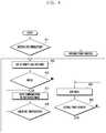
- FIG. 3is a flow diagram illustrating a process of setting an application for entering into a direct long DRX mode and setting a long DRX period in a device according to an exemplary embodiment of the present invention.
- the control unit 200determines whether the long DRX registration mode is specified in steps 311 and 313, and displays specific applications that are available for the long DRX mode in step 315. Displayed information may be any application that repeatedly opens RRC connection and has unimportant latency or may be any QCI.
- the control unit 200registers at least one application or QCI selected by the user through the input unit 280 in the direct long DRX mode in step 317.
- the DRX mode of a devicei.e., UE
- a base stationi.e., E-UTRAN, eNB, etc.
- the devicemay sometimes miss a command (such as a scheduling message or a MAC CE command) provided from the base station.
- periodic mutual synchronizationnamely, synchronization per longest DRX period
- the longest DRX period of LTEis 2560ms. Any excess period may cause a problem in synchronization between the device and the base station.
- the first field of the SFN (system frame number) 256 repeated by 2560ms from the SFN 1is always synchronized as the on-duration by the device and the base station.
- the base stationmay provide a necessary command to guarantee a reliable operation without missing a command.
- the control unit 200After specifying applications for performing the direct long DRX mode, the control unit 200 displays a DRX timer setting page for synchronization between the device and the base station in step 319 and registers a specific timer value selected by the user as a DRX timer for synchronization (namely, synchronization per longest DRX period) in step 321.
- the DRX timermay be set to 2560ms or less.
- the devicecompletes the setting of applications for performing the direct long DRX mode and the setting of the DRX timer for synchronization.
- the setting process shown in FIG. 3is implemented by the user, applications to perform the direct long DRX mode and the DRX timer for synchronization may be alternatively set up when the device is manufactured.
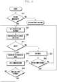
- FIG. 4is a flow diagram illustrating a process of performing a direct long DRX at a mobile device according to an exemplary embodiment of the present invention.
- the control unit 200when the device is powered on, the control unit 200 enters into the RRC_connected mode with the base station (i.e., default bearer). The device operates in the Always ON concept and performs the DRX mode in no communication state. If the user selects an application specified for the direct long DRX mode through the input unit 280, the control unit 200 recognizes a user selection in step 411 and sets up the direct long DRX mode in step 413.
- the base stationi.e., default bearer
- the control unit 200specifies a DRX setting timer (hereinafter, also referred to as a setting timer) used for a periodic communication with the base station in the long DRX mode, and also specifies an on-duration zone for the reception of PDCCH in a direct long DRX section.
- the DRX setting timerdetermines a specific section in which the DRX mode is performed .
- the on-duration zonedenotes a specific section to receive PDCCH data in the DRX section.
- the control unit 200may further set up a continuous canceling timer (i.e., a communication canceling timer, hereinafter referred to as a canceling timer) used for the transition from the continuous mode (i.e., a communication mode) to the direct long DRX mode.
- a continuous canceling timeri.e., a communication canceling timer, hereinafter referred to as a canceling timer
- the canceling timerdetermines the time of failure in reception of data packet in the continuous mode.
- the canceling timeris deactivated at the end of time interval, the control unit 200 cancels the continuous mode and performs a transition to the direct long DRX mode.
- a short DRX cycle timeras previously discussed in FIG. 1 may be used as the canceling timer or may be independently configured to perform the direct long DRX mode.
- the control unit 200supplies power to both the RF receiving unit 240 and the demodulation unit 250 by controlling the PMIC 220 so as to supply the power in the on-duration section.
- the control unit 200receives PDCCH data through the RF receiving unit 240 and the demodulation unit 250 and determines whether there is data to be transmitted to the control unit 200 in step 415. If there is no data to be transmitted as the result of the analysis of PDCCH data in step 415, the control unit 200 performs the transition to the long DRX mode in step 423.
- the control unit 200outputs a continuous power control signal to the PMIC 220 in step 417.
- the PMIC 220continuously supplies the power to the RF receiving unit 240 and the demodulation unit 250, and the control unit 200 receives and processes downlink data packet in the step 417.
- the control unit 200determines whether a communication is closed. The control unit 200 activates the canceling timer while data packet is not received, and then activates the canceling timer again just when data packet is received with the canceling timer activated. If no data packet is received until the deactivation of the canceling timer, the control unit 200 recognizes the close of a communication in step 419 and returns to step 413 to perform the transition to the direct long DRX mode.
- the control unit 200Since no power is supplied to the RF receiving unit 240 and the demodulation unit 250 in the direct long DRX mode in step 423, the control unit 200 does not perform data reception with power consumption reduced. In the direct long DRX mode, the control unit 200 determines whether the setting timer is deactivated in step 425. If the setting timer is deactivated in step 425, the control unit 200 returns to step 413 to activate the setting timer again and also to examine PDCCH data in the on-duration section specified in the step 415. Where the direct long DRX mode is performed, the device may be different in DRX mode from the base station. In this case, the device may miss a command (such as a scheduling message or a MAC CE command) downloaded from the base station. Accordingly, the control unit 200 of the device identifies missed commands through periodic mutual synchronization while performing the steps 423 and 425.
- a commandsuch as a scheduling message or a MAC CE command
- control unit 200cancels the direct long DRX mode and then performs other selected function.
- FIG. 5is a flow diagram illustrating a process of performing a direct long DRX in a browser application of a mobile device according to an exemplary embodiment of the present invention.
- the deviceaccesses the Internet and downloads information or data selected by the user (through a click, a touch, etc.).
- the devicemay enter into the continuous mode only during a download of information or data. While downloaded information or data is displayed after the completion of a download, the device does not need to receive downlink data.
- the control unit 200sets up the direct long DRX mode in step 513. As described above, the control unit 200 sets up the setting timer for setting the DRX mode and also sets up the canceling timer for canceling the continuous mode. The control unit 200 activates the setting timer, controls the PMIC 220 to supply the power to the RF receiving unit 240 and the demodulation unit 250 in the on-duration zone, receives PDCCH data in this zone, and performs sync per longest DRX period operation with the base station in step 515.
- the control unit 200determines whether there is an input requesting a download of data packet (i.e., whether a user's selection action such as a click for downloading data or information is detected) in step 517. If there is an input in step 517, the control unit 200 controls the PMIC 220 to operate in the continuous mode in step 519, and downloads and processes data of the browser link in step 521. In the continuous mode, the control unit 200 activates the canceling timer and determines the time of no data download in step 523. If data is not downloaded before the deactivation of the canceling timer in step 523, the control unit 200 returns to step 513 to perform the direct long DRX mode.
- a user's selection actionsuch as a click for downloading data or information is detected
- the deviceIn case of a browser application service, if data of a browser link is not received for a given time, the device does not perform the short DRX mode and immediately performs the transition to the direct long DRX mode. As described above, an immediate transition to the long DRX mode after data download reduces power consumption of the device, considering that a browser does not download additional data once the data is downloaded.
- the control unit 200performs the direct long DRX mode to reduce power consumption of the device in step 527 and determines whether the setting timer is deactivated in step 529. When the setting timer is deactivated in step 529, the control unit 200 returns to step 513. While repeatedly performing 527, 529, 513, 515 and 517, the control unit 200 performs the direct long DRX mode in response to no data input request and, in the on-duration of the direct long DRX mode, periodically checks control data transmitted from the synchronized base station.
- FIG. 6is a flow diagram illustrating a process of performing a direct long DRX in a messenger application of a mobile device according to an exemplary embodiment of the present invention.
- a messenger applicationdoes not have a given downlink point in time such as a click and does not always require high QoS as VoIP or streaming does.
- a messenger applicationmerely sends or receives text messages in turn, so the user may not feel a variation of QoS in spite of some latency. Accordingly, in the case of a messenger application, the device performs the transition to the direct long DRX mode when the user enters message letters, and cancels the direct long DRX mode when sender's text message is received. This process performed repeatedly may reduce latency.
- the control unit 200sets up the direct long DRX mode in step 613. As described above, the control unit 200 sets up the setting timer for setting the DRX mode and also sets up the canceling timer for canceling the continuous mode. The control unit 200 activates the setting timer, controls the PMIC 220 to supply the power to the RF receiving unit 240 and the demodulation unit 250 in the on-duration zone, receives PDCCH data in this zone, and performs sync per longest DRX period operation with the base station in step 615.
- the control unitperforms the DRX mode while the setting timer is activated in step 627.
- the control unit 200transmits messenger data through the transmitter.
- the control unit 200determines whether the setting timer is deactivated in step 629. When the setting timer is deactivated in step 629, the control unit 200 returns to step 613. While repeatedly performing the above steps, the control unit 200 performs the direct long DRX mode.
- the control unit 200recognizes this during a synchronization with the base station (namely, during reception of PDCCH data from the base station) in the step 615. If messenger data occurs from a subscriber, the device receives an indication of the messenger data from the base station via PDCCH data in step 617.
- the control unit 200controls the PMIC 220 to operate in the continuous mode in step 619 and receives messenger data from the sender through the RF receiving unit 240 and the demodulation unit 250 in step 621. In this case, the control unit 200 may recognize messenger data only after a time specified in the direct long DRX has passed. However, since a messenger application merely sends or receives text messages between the device user and other subscriber, they may not feel inconvenience in spite of some latency.
- the control unit 200activates the canceling timer and determines when the sender stops transmitting the messenger data in step 623. If there is no transmission of messenger data from the sender until the deactivation of the canceling timer in step 623, the control unit 200 returns to step 613 to perform the direct long DRX mode.
- the devicedoes not perform the short DRX mode and immediately performs the transition to the direct long DRX mode. An immediate transition to the long DRX mode during the transmission of message from the user reduces power consumption of the device, considering that a messenger exchanges text messages.
Landscapes
- Engineering & Computer Science (AREA)
- Computer Networks & Wireless Communication (AREA)
- Signal Processing (AREA)
- Mobile Radio Communication Systems (AREA)
- Telephone Function (AREA)
Description
- The present invention relates generally to communication control technology for mobile communication devices. More particularly, the present invention relates to a method for controlling a discontinuous reception in the mobile devices and a corresponding terminal.
- Typically, a discontinuous reception (DRX) operation of a mobile device is triggered by a timer or commands provided by a mobile communication system. A control operation for a discontinuous reception in a mobile device according to the related art is described below.
- One method for discontinuous reception operation method is based on a timer. This method is controlled by the network, depending on RRCConnectionReconfiguration Message, RRCConnectionSetup Message, RRCConnectionReestablishment Message, and drx-Config field (drx-Config in mac-MainConfig in RadioResourceConfigDedicated) contained in three OTA Messages. The drx-Config field is shown in Table 1.


- Another discontinuous reception operation method is based on commands, as shown in
FIG. 1 . FIG. 1 is a view illustrating a discontinuous reception operation based on commands in a mobile device according to the related art.- Referring to
FIG. 1 , the device may operate in a cycle of three modes (i.e., long DRX, short DRX, and continuous reception). In a mobile communication system, the continuous reception is triggered in response to a scheduling message reception as indicated by areference numeral 133, and PDCCH data can be found in all zones as indicated by areference numeral 113. The short DRX is triggered in response to the expiration of an inactivity timer or a Media Access Control (MAC) Control Element (CE) reception as indicated by areference numeral 135. PDCCH may be received only in the on-duration zone, and a DRX mode (sleep) is performed in the other zones. The long DRX is triggered in response to the expiration of a short DRX cycle timer as indicated by areference numeral 137. - In a mobile communication system according to the related art, the device performs DRX mode transition in response to only the value of a timer or commands provided by the system. However, in these methods, the device may operate in the continuous reception mode or short DRX mode even when data session is not actually used. This may cause the data reception standby time of the device to become longer. For example, when a browser or messenger application is used, mode transition is repeatedly made due to frequent download of low-capacity data. Repetition of circumstances where the device downloads data in the continuous reception mode and remains in the short DRX mode may unfavorably increase power consumption of the device.
WO-2008/111823-A1 provides a method of receiving a packet in a mobile communication system. According to both a type of service provided in the method and activity of packet data provided through the service, a mobile station operates in an operation level among DRX operation levels that are based on operation parameters of different values and receives a packet.- Qualcomm Incorporated: "Fast Dormancy", 3GPP Draft R2-106289 investigates the gain in terms of battery consumption of a previously proposed scheme. The scheme proposed that a user equipment could send a request to go to "power saving mode" if the user equipment does not expect more upload and download data, and it is up to an evolved node B whether to ignore the user equipment, send it to Long_DRX or send it to RRC_Idle. The scheme is investigated using two real-time traffic logs with energy consumption simulated based on different values of the inactivity timer.
- The invention is defined by independent claims 1 and 6. In the following, parts of the description and drawings referring to embodiments which are not covered by the claims are not presented as embodiments of the invention, but as examples useful for understanding the invention.
- It is an aim of certain embodiments of the present invention to provide a method for reducing power consumption through the transition of DRX modes according to circumstances in use of a device when the device operates in the Always ON concept after a booting process.
- Another aim of certain embodiments of the present invention is to provide a method for realizing an effective mode transition of the device by specifying a DRX mode having a long period with respect to a specific application having a period and unimportant latency and by performing the specified DRX mode when the specific application is executed.
- Another aim of certain embodiments of the present invention is to provide a method for realizing an effective mode transition of the device by specifying a DRX mode having a long period with respect to specific Quality of Service (QoS) Class Identifiers (QCIs) having lower QoS among QCIs of a mobile communication system and then by performing the specified DRX mode when the specific application is executed.
- In accordance with a first aspect of the present invention, a method for controlling discontinuous reception (DRX) in a mobile communication device is provided. The method includes, when a specific application is selected, activating a DRX setting timer defining a long DRX period and an on-duration section for a direct long DRX mode, which denotes a mode in which the mobile communication device performs a direct transition from a continuous mode to the long DRX mode without performing a short DRX mode, and awaiting the reception of control information from a base station in an on-duration section; and, when the DRX setting timer expires in the long DRX mode, reactivating the DRX setting timer and awaiting the reception of control information in an on-duration section; wherein in response to reception of valid control information, entering into the continuous mode for executing the specific application.
- There is further disclosed, a method for controlling a discontinuous reception (DRX) in a mobile communication device is provided. The method includes, when a specific application is selected, activating a DRX setting timer having a long DRX period for a direct long DRX mode, and entering into the DRX mode, when the setting timer expires in the DRX mode, activating the setting timer again and receiving control information from a base station in an on-duration zone, and entering into the DRX mode in response to no reception of valid control information in the on-duration zone, or entering into a continuous mode for executing the specific application in response to reception of valid control information.
- There is further disclosed a method for controlling a discontinuous reception (DRX) in a browser application of a mobile communication device is provided. The methodincludes, when the browser application is selected, activating a DRX setting timer having a long DRX period for a direct long DRX mode, and receiving control information from a base station in an on-duration zone; when valid control information is not received in the on-duration zone, entering into the DRX mode, when the setting timer expires in the DRX mode, activating the setting timer again and receiving the control information from the base station in the on-duration zone, and when the valid control information is received in the on-duration zone, entering into a continuous mode and processing downloaded information.
- There is further disclosed a method for controlling a discontinuous reception (DRX) in a messenger application of a mobile communication device is provided. The methodincludes when the messenger application is selected, activating a DRX setting timer having a long DRX period for a direct long DRX mode, and receiving control information from a base station in an on-duration zone, when valid control information is not received in the on-duration zone, entering into the DRX mode, when the setting timer expires in the DRX mode, activating the setting timer again and receiving the control information from the base station in the on-duration zone, and when the valid control information is received in the on-duration zone, entering into a continuous mode and processing received messenger data.
- In accordance with a second aspect of the present invention, a terminal is provided. The terminal includes a communication unit arranged to transmit and receive data; and a control unit arranged to activate a discontinuous reception, DRX, setting timer defining a long DRX mode and an on-duration section for a direct long DRX mode, which denotes a mode in which the terminal performs a direct transition from a continuous mode to the long DRX mode without performing a short DRX mode, and to await the reception of control information in an on-duration section when a specific application is selected, and, when the DRX setting timer expires in the long DRX mode, to reactivate the DRX setting timer and to await the reception of control information via the communication unit in an on-duration section; wherein the control unit is further arranged to enter into the continuous mode for executing the specific application in response to receiving valid control information via the communication unit.
- There is further disclosed, a terminal is provided. The terminal includes a communication unit for transmitting and receiving data, and a control unit for activating a discontinuous reception (DRX) setting timer for a direct long DRX mode and entering into the DRX mode when a specific application is selected, for reactivating the setting timer and waiting to receive control information from a base station via the communication unit in an on-duration zone when the setting timer expires in the DRX mode, and for entering into the DRX mode in response to failure to receive control information in the on-duration zone or entering into a continuous mode for executing the specific application in response to receiving valid control information from the base station via the communication unit.
- In the Always ON concept operation after a booting process, the device may perform the DRX mode having a long period depending on available applications and thereby reduces power consumption. With respect to a specific application having a period and unimportant latency or with respect to specific QCIs having relatively low QoS, the device may set up a DRX mode having a selectively long period and then performs such a DRX mode when the specific application is executed. Therefore, the number of mode transition may be reduced and power consumption also reduced.
- Other aspects, advantages, and salient features of the invention will become apparent to those skilled in the art from the following detailed description, which, taken in conjunction with the annexed drawings, discloses exemplary embodiments of the invention.
- The above and other aspects, features, and advantages of certain exemplary embodiments of the present invention will be more apparent from the following description taken in conjunction with the accompanying drawings, in which:
FIG. 1 is a view illustrating the transition among a short DRX mode, a long DRX mode, and a continuous reception mode in a mobile communication system according to the related art.FIG. 2 is a block diagram illustrating the structure of a mobile device according to an exemplary embodiment of the present invention.FIG. 3 is a flow diagram illustrating a process of setting an application for entering into a direct long DRX mode and setting a long DRX period in a device according to an exemplary embodiment of the present invention.FIG. 4 is a flow diagram illustrating a process of performing a direct long DRX at a mobile device according to an exemplary embodiment of the present invention.FIG. 5 is a flow diagram illustrating a process of performing a direct long DRX in a browser application of a mobile device according to an exemplary embodiment of the present invention.FIG. 6 is a flow diagram illustrating a process of performing a direct long DRX in a messenger application of a mobile device according to an exemplary embodiment of the present invention.- Throughout the drawings, it should be noted that like reference numbers are used to depict the same or similar elements, features, and structures.
- The following description with reference to the accompanying drawings is provided to assist in a comprehensive understanding of exemplary embodiments of the invention as defined by the claims. It includes various specific details to assist in that understanding. In addition, descriptions of well-known functions and constructions may be omitted for clarity and conciseness.
- The terms and words used in the following description and claims are not limited to the bibliographical meanings, but are merely used by the inventor to enable a clear and consistent understanding of the invention. Accordingly, it should be apparent to those skilled in the art that the following description of exemplary embodiments of the present invention is provided for illustration purposes only and not for the purpose of limiting the invention as defined by the appended claims.
- It is to be understood that the singular forms "a," "an," and "the" include plural referents unless the context clearly dictates otherwise. Thus, for example, reference to "a component surface" includes reference to one or more of such surfaces.
- Furthermore, well known or widely used techniques, elements, structures, and processes may not be described or illustrated in detail to avoid obscuring the essence of the present invention. Although the drawings represent exemplary embodiments of the invention, the drawings are not necessarily to scale and certain features may be exaggerated or omitted in order to better illustrate and explain the present invention.
- Among terms set forth herein, a "DRX mode" denotes a mode in which a mobile device performs a DRX operation. A "continuous mode" denotes a mode in which a mobile device performs a continuous reception operation. A "direct long DRX mode" denotes a mode in which a mobile device performs a direct transition from the continuous mode to the long DRX mode without performing a short DRX mode. A "setting timer" denotes a timer for setting a zone in which the direct long DRX mode is performed, namely for setting a period to the longest DRX period, defined in a mobile communication system, or less. A "canceling timer" denotes a timer for setting a time for a transition from the continuous mode to the direct long DRX mode. A "setting application" denotes an application that is set to use the direct long DRX mode by the user or device manufacturer.
- Long Term Evolution (LTE) systems and devices are now under active research and development. The LTE device operates in the Always on concept after a booting process and immediately receives EPS bearer context (IP information) or the like at the time of operation in the Always on concept. In this operation, the state of an RRC layer, which is one of the LTE protocol layers, becomes the RRC-CONNECTED state, so it is possible to always use data with less signaling. Additionally, since the LTE device may support the DRX mode even in the RRC-CONNECTED state, the LTE device realizes reduced power consumption in comparison with existing 2G or 3G devices. However, if the DRX period is determined only at the network in the DRX mode, the operation properties of applications of the device may not be reflected. Unfortunately, this may make it difficult to effectively control the power consumption of the device. Accordingly, if the device sets up the DRX mode and period in consideration of the operation properties of the device, it is possible to effectively reduce the power consumption of the device. An exemplary embodiment of the present invention proposes a method for setting the DRX mode and period in the device.
- A DRX function may be provided in the RRX_IDLE state and the RRC_CONNECTED state. Even though data transmission is carried out, the device may perform DRX operation and thus reduce considerably power consumption. The device repeats the on-duration and the DRX operation, depending on the DRX period. The on-duration denotes the time when the device wakes up and continuously performs data reception operation. The DRX period denotes an interval of time characterized by the repetition of the on-duration. According to an exemplary embodiment of the present invention, the device sets up the DRX mode and period, performs the reception of RDCCH during a specified on-duration, and if valid control information is not received for a specified time, sleeps while performing the DRX operation.
FIG. 2 is a block diagram illustrating the structure of a mobile device according to an exemplary embodiment of the present invention.- Referring to
FIG. 2 , aduplexer 230 is a filter that separates signals received and to be transmitted through an antenna. Amodulation unit 260 modulates an outgoing signal of each channel. Themodulation unit 260 includes a plurality of uplink channel transmitters, and may use OFDM (Orthogonal Frequency Division Multiplexing) technique for modulation. An RF (Radio Frequency)transmitting unit 270 converts in frequency outgoing signals of the baseband, output from themodulation unit 260, into the RF band and then sends the signals to theduplexer 230. AnRF receiving unit 240 converts in frequency RF signals, received through theduplexer 230, into signals of the baseband. Ademodulation unit 250 demodulates signals outputted from theRF receiving unit 240. Thedemodulation unit 250 includes a plurality of downlink channel receivers, and may user OFDM technique for demodulation. - A
control unit 200 controls the whole operation of the device and, in particular, controls operation in the DRX mode according to an exemplary embodiment of this invention. Amemory unit 210 stores programs and data of the device. Aninput unit 280 inputs commands and data for controlling the operation of the device. A PMIC (Power Management Integrated Circuit (PMIC) 220 controls power supply for elements of the device. According to an exemplary embodiment of the present invention, thePMIC 220 controls power supply for theRF receiver 240 and themodulation unit 250 in the DRX mode. - As described above, the device may perform the continuous mode, the short DRX mode, and the long DRX mode. Under specific conditions, it may be desirable to directly enter into the long DRX mode without performing the short DRX mode. For example, in case of some applications (e.g., browser, messenger, etc.) having a period and unimportant latency, it is possible to directly enter into the long DRX mode with regard to specific Quality of Service (QoS) Class Indicator (QCI) of LTE. The QCI is defined in the specification 23.203. It may be desirable to directly enter into the long DRX mode (a direct long DRX mode) without entering into the short DRX with regard to the sixth, eighth, and ninth QCIs in LTE QCI. In such cases, it may be desirable that the user can set applications for and/or QCIs for entering into the direct long DRX mode.
FIG. 3 is a flow diagram illustrating a process of setting an application for entering into a direct long DRX mode and setting a long DRX period in a device according to an exemplary embodiment of the present invention.- Referring to
FIG. 3 , thecontrol unit 200 determines whether the long DRX registration mode is specified insteps step 315. Displayed information may be any application that repeatedly opens RRC connection and has unimportant latency or may be any QCI. Thecontrol unit 200 registers at least one application or QCI selected by the user through theinput unit 280 in the direct long DRX mode instep 317. - If the direct long DRX method is used, the DRX mode of a device (i.e., UE) and of a base station (i.e., E-UTRAN, eNB, etc.) may vary. In this case, the device may sometimes miss a command (such as a scheduling message or a MAC CE command) provided from the base station. In order to remedy such a problem, periodic mutual synchronization (namely, synchronization per longest DRX period) is required to identify missed commands. At present, the longest DRX period of LTE is 2560ms. Any excess period may cause a problem in synchronization between the device and the base station. Accordingly, the first field of the SFN (system frame number) 256 repeated by 2560ms from the SFN 1 is always synchronized as the on-duration by the device and the base station. The base station may provide a necessary command to guarantee a reliable operation without missing a command.
- After specifying applications for performing the direct long DRX mode, the
control unit 200 displays a DRX timer setting page for synchronization between the device and the base station instep 319 and registers a specific timer value selected by the user as a DRX timer for synchronization (namely, synchronization per longest DRX period) instep 321. In the LTE system, the DRX timer may be set to 2560ms or less. - By implementing the process shown in
FIG. 3 , the device completes the setting of applications for performing the direct long DRX mode and the setting of the DRX timer for synchronization. Although the setting process shown inFIG. 3 is implemented by the user, applications to perform the direct long DRX mode and the DRX timer for synchronization may be alternatively set up when the device is manufactured. FIG. 4 is a flow diagram illustrating a process of performing a direct long DRX at a mobile device according to an exemplary embodiment of the present invention.- Referring to
FIG. 4 , when the device is powered on, thecontrol unit 200 enters into the RRC_connected mode with the base station (i.e., default bearer). The device operates in the Always ON concept and performs the DRX mode in no communication state. If the user selects an application specified for the direct long DRX mode through theinput unit 280, thecontrol unit 200 recognizes a user selection instep 411 and sets up the direct long DRX mode instep 413. - In
step 413, thecontrol unit 200 specifies a DRX setting timer (hereinafter, also referred to as a setting timer) used for a periodic communication with the base station in the long DRX mode, and also specifies an on-duration zone for the reception of PDCCH in a direct long DRX section. The DRX setting timer determines a specific section in which the DRX mode is performed .The on-duration zone denotes a specific section to receive PDCCH data in the DRX section. Additionally, instep 413, thecontrol unit 200 may further set up a continuous canceling timer (i.e., a communication canceling timer, hereinafter referred to as a canceling timer) used for the transition from the continuous mode (i.e., a communication mode) to the direct long DRX mode. The canceling timer determines the time of failure in reception of data packet in the continuous mode. When the canceling timer is deactivated at the end of time interval, thecontrol unit 200 cancels the continuous mode and performs a transition to the direct long DRX mode. A short DRX cycle timer as previously discussed inFIG. 1 may be used as the canceling timer or may be independently configured to perform the direct long DRX mode. - When the DRX setting timer is activated in the direct long DRX mode, the
control unit 200 supplies power to both theRF receiving unit 240 and thedemodulation unit 250 by controlling thePMIC 220 so as to supply the power in the on-duration section. Thecontrol unit 200 receives PDCCH data through theRF receiving unit 240 and thedemodulation unit 250 and determines whether there is data to be transmitted to thecontrol unit 200 instep 415. If there is no data to be transmitted as the result of the analysis of PDCCH data instep 415, thecontrol unit 200 performs the transition to the long DRX mode instep 423. - However, if there is data to be transmitted as the result of the analysis of PDCCH data in
step 415, thecontrol unit 200 outputs a continuous power control signal to thePMIC 220 instep 417. ThePMIC 220 continuously supplies the power to theRF receiving unit 240 and thedemodulation unit 250, and thecontrol unit 200 receives and processes downlink data packet in thestep 417. In the continuous mode, thecontrol unit 200 determines whether a communication is closed. Thecontrol unit 200 activates the canceling timer while data packet is not received, and then activates the canceling timer again just when data packet is received with the canceling timer activated. If no data packet is received until the deactivation of the canceling timer, thecontrol unit 200 recognizes the close of a communication instep 419 and returns to step 413 to perform the transition to the direct long DRX mode. - Since no power is supplied to the
RF receiving unit 240 and thedemodulation unit 250 in the direct long DRX mode instep 423, thecontrol unit 200 does not perform data reception with power consumption reduced. In the direct long DRX mode, thecontrol unit 200 determines whether the setting timer is deactivated in step 425. If the setting timer is deactivated in step 425, thecontrol unit 200 returns to step 413 to activate the setting timer again and also to examine PDCCH data in the on-duration section specified in thestep 415. Where the direct long DRX mode is performed, the device may be different in DRX mode from the base station. In this case, the device may miss a command (such as a scheduling message or a MAC CE command) downloaded from the base station. Accordingly, thecontrol unit 200 of the device identifies missed commands through periodic mutual synchronization while performing thesteps 423 and 425. - If the application is terminated while running in the direct long DRX mode, the
control unit 200 cancels the direct long DRX mode and then performs other selected function. FIG. 5 is a flow diagram illustrating a process of performing a direct long DRX in a browser application of a mobile device according to an exemplary embodiment of the present invention.- Referring to
FIG. 5 , when a browser application is selected, the device accesses the Internet and downloads information or data selected by the user (through a click, a touch, etc.). The device may enter into the continuous mode only during a download of information or data. While downloaded information or data is displayed after the completion of a download, the device does not need to receive downlink data. - When a browser application is selected in
step 511, thecontrol unit 200 sets up the direct long DRX mode instep 513. As described above, thecontrol unit 200 sets up the setting timer for setting the DRX mode and also sets up the canceling timer for canceling the continuous mode. Thecontrol unit 200 activates the setting timer, controls thePMIC 220 to supply the power to theRF receiving unit 240 and thedemodulation unit 250 in the on-duration zone, receives PDCCH data in this zone, and performs sync per longest DRX period operation with the base station instep 515. - The
control unit 200 determines whether there is an input requesting a download of data packet (i.e., whether a user's selection action such as a click for downloading data or information is detected) instep 517. If there is an input instep 517, thecontrol unit 200 controls thePMIC 220 to operate in the continuous mode instep 519, and downloads and processes data of the browser link instep 521. In the continuous mode, thecontrol unit 200 activates the canceling timer and determines the time of no data download instep 523. If data is not downloaded before the deactivation of the canceling timer instep 523, thecontrol unit 200 returns to step 513 to perform the direct long DRX mode. In case of a browser application service, if data of a browser link is not received for a given time, the device does not perform the short DRX mode and immediately performs the transition to the direct long DRX mode. As described above, an immediate transition to the long DRX mode after data download reduces power consumption of the device, considering that a browser does not download additional data once the data is downloaded. - If there is no input of a download request in
step 517, thecontrol unit 200 performs the direct long DRX mode to reduce power consumption of the device instep 527 and determines whether the setting timer is deactivated instep 529. When the setting timer is deactivated instep 529, thecontrol unit 200 returns to step 513. While repeatedly performing 527, 529, 513, 515 and 517, thecontrol unit 200 performs the direct long DRX mode in response to no data input request and, in the on-duration of the direct long DRX mode, periodically checks control data transmitted from the synchronized base station. FIG. 6 is a flow diagram illustrating a process of performing a direct long DRX in a messenger application of a mobile device according to an exemplary embodiment of the present invention.- Referring to
FIG. 6 , a messenger application does not have a given downlink point in time such as a click and does not always require high QoS as VoIP or streaming does. A messenger application merely sends or receives text messages in turn, so the user may not feel a variation of QoS in spite of some latency. Accordingly, in the case of a messenger application, the device performs the transition to the direct long DRX mode when the user enters message letters, and cancels the direct long DRX mode when sender's text message is received. This process performed repeatedly may reduce latency. - When a messenger application is selected in
step 611, thecontrol unit 200 sets up the direct long DRX mode instep 613. As described above, thecontrol unit 200 sets up the setting timer for setting the DRX mode and also sets up the canceling timer for canceling the continuous mode. Thecontrol unit 200 activates the setting timer, controls thePMIC 220 to supply the power to theRF receiving unit 240 and thedemodulation unit 250 in the on-duration zone, receives PDCCH data in this zone, and performs sync per longest DRX period operation with the base station instep 615. - If there is no data to be inputted to the device in
step 617, the control unit performs the DRX mode while the setting timer is activated instep 627. In the DRX mode, thecontrol unit 200 transmits messenger data through the transmitter. Thecontrol unit 200 determines whether the setting timer is deactivated instep 629. When the setting timer is deactivated instep 629, thecontrol unit 200 returns to step 613. While repeatedly performing the above steps, thecontrol unit 200 performs the direct long DRX mode. - If there is a reception request for messenger data from a sender (i.e., another subscriber) in the DRX mode, the
control unit 200 recognizes this during a synchronization with the base station (namely, during reception of PDCCH data from the base station) in thestep 615. If messenger data occurs from a subscriber, the device receives an indication of the messenger data from the base station via PDCCH data instep 617. Thecontrol unit 200 controls thePMIC 220 to operate in the continuous mode instep 619 and receives messenger data from the sender through theRF receiving unit 240 and thedemodulation unit 250 instep 621. In this case, thecontrol unit 200 may recognize messenger data only after a time specified in the direct long DRX has passed. However, since a messenger application merely sends or receives text messages between the device user and other subscriber, they may not feel inconvenience in spite of some latency. - In the continuous mode, the
control unit 200 activates the canceling timer and determines when the sender stops transmitting the messenger data instep 623. If there is no transmission of messenger data from the sender until the deactivation of the canceling timer instep 623, thecontrol unit 200 returns to step 613 to perform the direct long DRX mode. In case of a messenger application service, if messenger data is not received from other subscriber for a given time, the device does not perform the short DRX mode and immediately performs the transition to the direct long DRX mode. An immediate transition to the long DRX mode during the transmission of message from the user reduces power consumption of the device, considering that a messenger exchanges text messages. - This invention has been shown and described with reference to an exemplary embodiment thereof. The scope of the invention is defined by the appended claims.


Claims (11)
- A method for controlling discontinuous reception, DRX, in a mobile communication device, the method comprising:when a specific application is selected (411), activating (413) a DRX setting timer defining a long DRX period and an on-duration section for a direct long DRX mode, which denotes a mode in which the mobile communication device performs a direct transition from a continuous mode to the long DRX mode without performing a short DRX mode, and awaiting (415) the reception of control information from a base station in an on-duration section; andwhen the DRX setting timer expires (425) in the long DRX mode, reactivating the DRX setting timer (413) and awaiting (415) the reception of control information in an on-duration section;wherein in response to reception of valid control information, the method further comprises entering (417) into the continuous mode for executing (417) the specific application.
- The method of claim 1, further comprising:
if there is no reception data in the continuous mode until the expiration (419) of a continuous canceling timer, activating (413) the DRX setting timer and awaiting (415) the reception of control information from a base station in an on-duration section. - The method of claim 2, further comprising:
registering (317) the direct long DRX mode, the registering of the direct long DRX mode including:specifying (319) the specific application for performing the direct long DRX mode;specifying (321) the period of the DRX setting timer and the on-duration section; andspecifying (321) a period of the continuous canceling timer. - The method of claim 1 or 3, wherein the specific application is a browser application (511) or a messenger application (611), and wherein executing (417) the specific application comprises processing downloaded information (521) or processing received messenger data (621) respectively.
- The method of claim 4, wherein the period of the DRX setting timer is less than or equal to the longest DRX period defined in a mobile communication system.
- A terminal, comprising:a communication unit (230-270) arranged to transmit and receive data; anda control unit (200) arranged to activate (413) a discontinuous reception, DRX, setting timer defining a long DRX mode and an on-duration section for a direct long DRX mode, which denotes a mode in which the terminal performs a direct transition from a continuous mode to the long DRX mode without performing a short DRX mode, and to await (415) the reception of control information in an on-duration section when a specific application is selected, and, when the DRX setting timer expires in the long DRX mode, to reactivate (413) the DRX setting timer and to await (415) the reception of control information via the communication unit (230-270) in an on-duration section;wherein the control unit (200) is further arranged to enter (417) into the continuous mode for executing (417) the specific application in response to receiving valid control information via the communication unit (230-270).
- The terminal of claim 6, wherein the control unit (200) is further arranged to register one of a plurality of applications stored in a storage unit (210) of the terminal as the specific application.
- The terminal of claim 7, wherein the plurality of applications are applications which repeatedly open a Radio Resource Control, RRC, connection and do not require a predetermined latency for operation.
- The terminal of claim 7, wherein the control unit (200) is further arranged to register one of the plurality of applications as the specific application according to input from a user of the terminal.
- The terminal of claim 7, wherein the control unit (200) is further arranged to register one of the plurality of applications as the specific application according to input from a manufacturer of the terminal.
- The terminal of claim 6, wherein the specific application is a browser application or a messenger application.
Applications Claiming Priority (1)
| Application Number | Priority Date | Filing Date | Title |
|---|---|---|---|
| KR1020110068290AKR101790036B1 (en) | 2011-07-11 | 2011-07-11 | Method for controlling discontinuous reception in mobile terminal |
Publications (2)
| Publication Number | Publication Date |
|---|---|
| EP2547166A1 EP2547166A1 (en) | 2013-01-16 |
| EP2547166B1true EP2547166B1 (en) | 2019-06-05 |
Family
ID=46466113
Family Applications (1)
| Application Number | Title | Priority Date | Filing Date |
|---|---|---|---|
| EP12171533.8ANot-in-forceEP2547166B1 (en) | 2011-07-11 | 2012-06-11 | Method for controlling discontinuous reception in mobile communication device and corresponding terminal |
Country Status (4)
| Country | Link |
|---|---|
| US (1) | US8953509B2 (en) |
| EP (1) | EP2547166B1 (en) |
| KR (1) | KR101790036B1 (en) |
| CN (1) | CN102883417B (en) |
Families Citing this family (21)
| Publication number | Priority date | Publication date | Assignee | Title |
|---|---|---|---|---|
| EP2727305A4 (en) | 2011-07-01 | 2015-01-07 | Intel Corp | LAYER SHIFTING IN MULTIPLE INPUT COMMUNICATIONS, MULTIPLE OPEN LOOP OUTPUTS |
| US8953478B2 (en)* | 2012-01-27 | 2015-02-10 | Intel Corporation | Evolved node B and method for coherent coordinated multipoint transmission with per CSI-RS feedback |
| JP2014072637A (en)* | 2012-09-28 | 2014-04-21 | Ntt Docomo Inc | Mobile station and radio base station |
| US8989096B2 (en)* | 2012-10-15 | 2015-03-24 | Apple Inc. | Application-aware radio power saving |
| CN104620515B (en)* | 2012-11-29 | 2018-02-16 | Lg电子株式会社 | Method and apparatus for the DRX operations in radio communication |
| JP6102324B2 (en)* | 2013-02-20 | 2017-03-29 | 株式会社デンソー | Communications system |
| JP6094297B2 (en) | 2013-03-21 | 2017-03-15 | 富士通株式会社 | Wireless terminal device, communication control device, and wireless communication method |
| EP2785082B1 (en)* | 2013-03-27 | 2021-06-16 | Sony Corporation | Method for operating a terminal device |
| WO2014158067A1 (en)* | 2013-03-28 | 2014-10-02 | Telefonaktiebolaget L M Ericsson (Publ) | Optimizing channel state switch based on the traffic volume indicator (tvi) values associated with throughputs on the communication links |
| US9877352B2 (en)* | 2013-04-15 | 2018-01-23 | Telefonaktiebolaget Lm Ericsson (Publ) | Application of a discontinuous reception (DRX) cycle |
| WO2014179915A1 (en)* | 2013-05-06 | 2014-11-13 | 华为技术有限公司 | Drx operation method, user equipment, and base station |
| US10499451B2 (en) | 2014-06-13 | 2019-12-03 | Apple Inc. | Adaptive C-DRX management |
| US9374781B2 (en)* | 2014-07-14 | 2016-06-21 | Amazon Technologies, Inc. | Method for discontinuous reception (DRX) in dual connectivity |
| US20160081020A1 (en)* | 2014-09-16 | 2016-03-17 | Telefonaktiebolaget L M Ericsson (Publ) | Drx cycle configuration in dual connectivity |
| CN108307406B (en)* | 2016-09-30 | 2020-03-06 | 电信科学技术研究院 | Discontinuous reception method and related device |
| US10701756B2 (en)* | 2017-05-16 | 2020-06-30 | Qualcomm Incorporated | Service specific short DRX cycles |
| WO2019064221A1 (en)* | 2017-09-28 | 2019-04-04 | L&T Technology Services Limited | Method and device for waking up a wireless device |
| CN110267287B (en)* | 2018-03-12 | 2022-10-14 | 苏州速通半导体科技有限公司 | A method for performing full-duplex communication in the TWT service interval of an efficient wireless local area network |
| WO2020087198A1 (en)* | 2018-10-29 | 2020-05-07 | 北京小米移动软件有限公司 | Timer control method and apparatus, electronic device, and computer readable storage medium |
| CN111278171B (en) | 2019-01-31 | 2022-05-17 | 维沃移动通信有限公司 | Discontinuous reception DRX configuration method and terminal |
| EP3927053B1 (en)* | 2019-02-18 | 2023-09-06 | Beijing Xiaomi Mobile Software Co., Ltd. | Method, terminal storage medium for operating a drx timer |
Family Cites Families (7)
| Publication number | Priority date | Publication date | Assignee | Title |
|---|---|---|---|---|
| WO2008111684A1 (en) | 2007-03-12 | 2008-09-18 | Sharp Kabushiki Kaisha | Flexible user equipment-specified discontinuous reception |
| US20100034145A1 (en) | 2007-03-15 | 2010-02-11 | Samsung Electronics Co., Ltd. | Method for receiving packet in mobile communication system |
| CN105188121B (en)* | 2007-09-03 | 2019-02-22 | 爱立信电话股份有限公司 | Discontinuous transmission and reception |
| US8249004B2 (en)* | 2008-03-14 | 2012-08-21 | Interdigital Patent Holdings, Inc. | Coordinated uplink transmission in LTE DRX operations for a wireless transmit receive unit |
| US8265682B2 (en)* | 2008-03-18 | 2012-09-11 | Texas Instruments Incorporated | Scheduling request usage in DRX mode in wireless networks |
| US20110002281A1 (en)* | 2008-12-30 | 2011-01-06 | Interdigital Patent Holdings, Inc. | Discontinuous reception for carrier aggregation |
| CN102036348B (en)* | 2009-09-30 | 2014-01-01 | 中兴通讯股份有限公司 | A discontinuous reception configuration method and system |
- 2011
- 2011-07-11KRKR1020110068290Apatent/KR101790036B1/ennot_activeExpired - Fee Related
- 2012
- 2012-06-07USUS13/490,794patent/US8953509B2/ennot_activeExpired - Fee Related
- 2012-06-11EPEP12171533.8Apatent/EP2547166B1/ennot_activeNot-in-force
- 2012-07-11CNCN201210240659.5Apatent/CN102883417B/ennot_activeExpired - Fee Related
Non-Patent Citations (1)
| Title |
|---|
| None* |
Also Published As
| Publication number | Publication date |
|---|---|
| US8953509B2 (en) | 2015-02-10 |
| CN102883417B (en) | 2017-09-01 |
| KR101790036B1 (en) | 2017-10-25 |
| EP2547166A1 (en) | 2013-01-16 |
| US20130016638A1 (en) | 2013-01-17 |
| CN102883417A (en) | 2013-01-16 |
| KR20130007766A (en) | 2013-01-21 |
Similar Documents
| Publication | Publication Date | Title |
|---|---|---|
| EP2547166B1 (en) | Method for controlling discontinuous reception in mobile communication device and corresponding terminal | |
| US9832809B2 (en) | Method and apparatus for controlling discontinuous reception in a wireless communication system | |
| EP3520521B1 (en) | Active time handling with 2-step granting | |
| US10292100B2 (en) | Method and apparatus for indicating and adapting the activity state of a wireless device having device-to-device communication capabilities | |
| EP3419365A1 (en) | Method for discontinuous reception operation for long term evolution advanced carrier aggregation | |
| WO2021185266A1 (en) | Methods for physical downlink control channel (pdcch) monitoring adaptation in 5g new radio (nr) | |
| CN110881208B (en) | A communication method and device | |
| CN102487541A (en) | UE power saving method and system thereof | |
| KR20140041954A (en) | Method and apparatus for enhancing discontinuous reception in wireless systems | |
| CN102577165A (en) | Method and system for transmitting/receiving data in a wireless communication system | |
| KR102196546B1 (en) | DRX and scheduling optimization method to reduce the power consumption of the terminal in the IOT environment | |
| JP2025016763A (en) | Method for operating a communication device and a communication device | |
| US20180270897A1 (en) | Apparatus and method for providing power saving during idle to connected mode transitions | |
| CN102932884A (en) | Method and system for realizing DRX (Discontinuous Reception) | |
| CN110574444B (en) | Method, device, terminal and medium for dynamically changing parameter of power-saving signal | |
| EP4199605A1 (en) | Transmission control method and apparatus, and related device | |
| CN118383054A (en) | Wireless communication method, terminal device and network device | |
| WO2024132455A1 (en) | Method, apparatus, and system for multiple drx management in a wireless network | |
| KR20130126403A (en) | Method and apparatus of drx reconfiguration considering packet inter arrival time | |
| WO2021259343A1 (en) | Efficient adaption of ue power saving in 5g new radio (nr) |
Legal Events
| Date | Code | Title | Description |
|---|---|---|---|
| PUAI | Public reference made under article 153(3) epc to a published international application that has entered the european phase | Free format text:ORIGINAL CODE: 0009012 | |
| AK | Designated contracting states | Kind code of ref document:A1 Designated state(s):AL AT BE BG CH CY CZ DE DK EE ES FI FR GB GR HR HU IE IS IT LI LT LU LV MC MK MT NL NO PL PT RO RS SE SI SK SM TR | |
| AX | Request for extension of the european patent | Extension state:BA ME | |
| 17P | Request for examination filed | Effective date:20130715 | |
| REG | Reference to a national code | Ref country code:DE Ref legal event code:R079 Ref document number:602012060664 Country of ref document:DE Free format text:PREVIOUS MAIN CLASS: H04W0076040000 Ipc:H04W0052020000 | |
| GRAP | Despatch of communication of intention to grant a patent | Free format text:ORIGINAL CODE: EPIDOSNIGR1 | |
| STAA | Information on the status of an ep patent application or granted ep patent | Free format text:STATUS: GRANT OF PATENT IS INTENDED | |
| RIC1 | Information provided on ipc code assigned before grant | Ipc:H04W 52/02 20090101AFI20181122BHEP Ipc:H04W 76/28 20180101ALI20181122BHEP Ipc:H04W 76/27 20180101ALN20181122BHEP | |
| RIC1 | Information provided on ipc code assigned before grant | Ipc:H04W 76/27 20180101ALN20181127BHEP Ipc:H04W 52/02 20090101AFI20181127BHEP Ipc:H04W 76/28 20180101ALI20181127BHEP | |
| INTG | Intention to grant announced | Effective date:20181211 | |
| RIC1 | Information provided on ipc code assigned before grant | Ipc:H04W 76/28 20180101ALI20181127BHEP Ipc:H04W 76/27 20180101ALN20181127BHEP Ipc:H04W 52/02 20090101AFI20181127BHEP | |
| GRAS | Grant fee paid | Free format text:ORIGINAL CODE: EPIDOSNIGR3 | |
| GRAA | (expected) grant | Free format text:ORIGINAL CODE: 0009210 | |
| STAA | Information on the status of an ep patent application or granted ep patent | Free format text:STATUS: THE PATENT HAS BEEN GRANTED | |
| AK | Designated contracting states | Kind code of ref document:B1 Designated state(s):AL AT BE BG CH CY CZ DE DK EE ES FI FR GB GR HR HU IE IS IT LI LT LU LV MC MK MT NL NO PL PT RO RS SE SI SK SM TR | |
| REG | Reference to a national code | Ref country code:GB Ref legal event code:FG4D | |
| REG | Reference to a national code | Ref country code:CH Ref legal event code:EP | |
| REG | Reference to a national code | Ref country code:AT Ref legal event code:REF Ref document number:1141258 Country of ref document:AT Kind code of ref document:T Effective date:20190615 | |
| REG | Reference to a national code | Ref country code:IE Ref legal event code:FG4D | |
| REG | Reference to a national code | Ref country code:DE Ref legal event code:R096 Ref document number:602012060664 Country of ref document:DE | |
| REG | Reference to a national code | Ref country code:NL Ref legal event code:MP Effective date:20190605 | |
| REG | Reference to a national code | Ref country code:LT Ref legal event code:MG4D | |
| PG25 | Lapsed in a contracting state [announced via postgrant information from national office to epo] | Ref country code:AL Free format text:LAPSE BECAUSE OF FAILURE TO SUBMIT A TRANSLATION OF THE DESCRIPTION OR TO PAY THE FEE WITHIN THE PRESCRIBED TIME-LIMIT Effective date:20190605 Ref country code:SE Free format text:LAPSE BECAUSE OF FAILURE TO SUBMIT A TRANSLATION OF THE DESCRIPTION OR TO PAY THE FEE WITHIN THE PRESCRIBED TIME-LIMIT Effective date:20190605 Ref country code:LT Free format text:LAPSE BECAUSE OF FAILURE TO SUBMIT A TRANSLATION OF THE DESCRIPTION OR TO PAY THE FEE WITHIN THE PRESCRIBED TIME-LIMIT Effective date:20190605 Ref country code:HR Free format text:LAPSE BECAUSE OF FAILURE TO SUBMIT A TRANSLATION OF THE DESCRIPTION OR TO PAY THE FEE WITHIN THE PRESCRIBED TIME-LIMIT Effective date:20190605 Ref country code:ES Free format text:LAPSE BECAUSE OF FAILURE TO SUBMIT A TRANSLATION OF THE DESCRIPTION OR TO PAY THE FEE WITHIN THE PRESCRIBED TIME-LIMIT Effective date:20190605 Ref country code:FI Free format text:LAPSE BECAUSE OF FAILURE TO SUBMIT A TRANSLATION OF THE DESCRIPTION OR TO PAY THE FEE WITHIN THE PRESCRIBED TIME-LIMIT Effective date:20190605 Ref country code:NO Free format text:LAPSE BECAUSE OF FAILURE TO SUBMIT A TRANSLATION OF THE DESCRIPTION OR TO PAY THE FEE WITHIN THE PRESCRIBED TIME-LIMIT Effective date:20190905 | |
| PG25 | Lapsed in a contracting state [announced via postgrant information from national office to epo] | Ref country code:GR Free format text:LAPSE BECAUSE OF FAILURE TO SUBMIT A TRANSLATION OF THE DESCRIPTION OR TO PAY THE FEE WITHIN THE PRESCRIBED TIME-LIMIT Effective date:20190906 Ref country code:BG Free format text:LAPSE BECAUSE OF FAILURE TO SUBMIT A TRANSLATION OF THE DESCRIPTION OR TO PAY THE FEE WITHIN THE PRESCRIBED TIME-LIMIT Effective date:20190905 Ref country code:LV Free format text:LAPSE BECAUSE OF FAILURE TO SUBMIT A TRANSLATION OF THE DESCRIPTION OR TO PAY THE FEE WITHIN THE PRESCRIBED TIME-LIMIT Effective date:20190605 Ref country code:RS Free format text:LAPSE BECAUSE OF FAILURE TO SUBMIT A TRANSLATION OF THE DESCRIPTION OR TO PAY THE FEE WITHIN THE PRESCRIBED TIME-LIMIT Effective date:20190605 | |
| REG | Reference to a national code | Ref country code:DE Ref legal event code:R119 Ref document number:602012060664 Country of ref document:DE | |
| REG | Reference to a national code | Ref country code:AT Ref legal event code:MK05 Ref document number:1141258 Country of ref document:AT Kind code of ref document:T Effective date:20190605 | |
| PG25 | Lapsed in a contracting state [announced via postgrant information from national office to epo] | Ref country code:AT Free format text:LAPSE BECAUSE OF FAILURE TO SUBMIT A TRANSLATION OF THE DESCRIPTION OR TO PAY THE FEE WITHIN THE PRESCRIBED TIME-LIMIT Effective date:20190605 Ref country code:NL Free format text:LAPSE BECAUSE OF FAILURE TO SUBMIT A TRANSLATION OF THE DESCRIPTION OR TO PAY THE FEE WITHIN THE PRESCRIBED TIME-LIMIT Effective date:20190605 Ref country code:PT Free format text:LAPSE BECAUSE OF FAILURE TO SUBMIT A TRANSLATION OF THE DESCRIPTION OR TO PAY THE FEE WITHIN THE PRESCRIBED TIME-LIMIT Effective date:20191007 Ref country code:SK Free format text:LAPSE BECAUSE OF FAILURE TO SUBMIT A TRANSLATION OF THE DESCRIPTION OR TO PAY THE FEE WITHIN THE PRESCRIBED TIME-LIMIT Effective date:20190605 Ref country code:CZ Free format text:LAPSE BECAUSE OF FAILURE TO SUBMIT A TRANSLATION OF THE DESCRIPTION OR TO PAY THE FEE WITHIN THE PRESCRIBED TIME-LIMIT Effective date:20190605 Ref country code:RO Free format text:LAPSE BECAUSE OF FAILURE TO SUBMIT A TRANSLATION OF THE DESCRIPTION OR TO PAY THE FEE WITHIN THE PRESCRIBED TIME-LIMIT Effective date:20190605 Ref country code:EE Free format text:LAPSE BECAUSE OF FAILURE TO SUBMIT A TRANSLATION OF THE DESCRIPTION OR TO PAY THE FEE WITHIN THE PRESCRIBED TIME-LIMIT Effective date:20190605 | |
| REG | Reference to a national code | Ref country code:CH Ref legal event code:PL | |
| PG25 | Lapsed in a contracting state [announced via postgrant information from national office to epo] | Ref country code:IT Free format text:LAPSE BECAUSE OF FAILURE TO SUBMIT A TRANSLATION OF THE DESCRIPTION OR TO PAY THE FEE WITHIN THE PRESCRIBED TIME-LIMIT Effective date:20190605 Ref country code:SM Free format text:LAPSE BECAUSE OF FAILURE TO SUBMIT A TRANSLATION OF THE DESCRIPTION OR TO PAY THE FEE WITHIN THE PRESCRIBED TIME-LIMIT Effective date:20190605 Ref country code:IS Free format text:LAPSE BECAUSE OF FAILURE TO SUBMIT A TRANSLATION OF THE DESCRIPTION OR TO PAY THE FEE WITHIN THE PRESCRIBED TIME-LIMIT Effective date:20191005 | |
| REG | Reference to a national code | Ref country code:BE Ref legal event code:MM Effective date:20190630 | |
| PG25 | Lapsed in a contracting state [announced via postgrant information from national office to epo] | Ref country code:TR Free format text:LAPSE BECAUSE OF FAILURE TO SUBMIT A TRANSLATION OF THE DESCRIPTION OR TO PAY THE FEE WITHIN THE PRESCRIBED TIME-LIMIT Effective date:20190605 Ref country code:MC Free format text:LAPSE BECAUSE OF FAILURE TO SUBMIT A TRANSLATION OF THE DESCRIPTION OR TO PAY THE FEE WITHIN THE PRESCRIBED TIME-LIMIT Effective date:20190605 | |
| PLBE | No opposition filed within time limit | Free format text:ORIGINAL CODE: 0009261 | |
| STAA | Information on the status of an ep patent application or granted ep patent | Free format text:STATUS: NO OPPOSITION FILED WITHIN TIME LIMIT | |
| PG25 | Lapsed in a contracting state [announced via postgrant information from national office to epo] | Ref country code:PL Free format text:LAPSE BECAUSE OF FAILURE TO SUBMIT A TRANSLATION OF THE DESCRIPTION OR TO PAY THE FEE WITHIN THE PRESCRIBED TIME-LIMIT Effective date:20190605 Ref country code:DE Free format text:LAPSE BECAUSE OF NON-PAYMENT OF DUE FEES Effective date:20200101 Ref country code:IE Free format text:LAPSE BECAUSE OF NON-PAYMENT OF DUE FEES Effective date:20190611 Ref country code:DK Free format text:LAPSE BECAUSE OF FAILURE TO SUBMIT A TRANSLATION OF THE DESCRIPTION OR TO PAY THE FEE WITHIN THE PRESCRIBED TIME-LIMIT Effective date:20190605 | |
| 26N | No opposition filed | Effective date:20200306 | |
| PG25 | Lapsed in a contracting state [announced via postgrant information from national office to epo] | Ref country code:LI Free format text:LAPSE BECAUSE OF NON-PAYMENT OF DUE FEES Effective date:20190630 Ref country code:CH Free format text:LAPSE BECAUSE OF NON-PAYMENT OF DUE FEES Effective date:20190630 Ref country code:SI Free format text:LAPSE BECAUSE OF FAILURE TO SUBMIT A TRANSLATION OF THE DESCRIPTION OR TO PAY THE FEE WITHIN THE PRESCRIBED TIME-LIMIT Effective date:20190605 Ref country code:LU Free format text:LAPSE BECAUSE OF NON-PAYMENT OF DUE FEES Effective date:20190611 Ref country code:BE Free format text:LAPSE BECAUSE OF NON-PAYMENT OF DUE FEES Effective date:20190630 | |
| PG25 | Lapsed in a contracting state [announced via postgrant information from national office to epo] | Ref country code:FR Free format text:LAPSE BECAUSE OF NON-PAYMENT OF DUE FEES Effective date:20190805 | |
| PGFP | Annual fee paid to national office [announced via postgrant information from national office to epo] | Ref country code:GB Payment date:20200522 Year of fee payment:9 | |
| PG25 | Lapsed in a contracting state [announced via postgrant information from national office to epo] | Ref country code:CY Free format text:LAPSE BECAUSE OF FAILURE TO SUBMIT A TRANSLATION OF THE DESCRIPTION OR TO PAY THE FEE WITHIN THE PRESCRIBED TIME-LIMIT Effective date:20190605 | |
| PG25 | Lapsed in a contracting state [announced via postgrant information from national office to epo] | Ref country code:MT Free format text:LAPSE BECAUSE OF FAILURE TO SUBMIT A TRANSLATION OF THE DESCRIPTION OR TO PAY THE FEE WITHIN THE PRESCRIBED TIME-LIMIT Effective date:20190605 Ref country code:HU Free format text:LAPSE BECAUSE OF FAILURE TO SUBMIT A TRANSLATION OF THE DESCRIPTION OR TO PAY THE FEE WITHIN THE PRESCRIBED TIME-LIMIT; INVALID AB INITIO Effective date:20120611 | |
| GBPC | Gb: european patent ceased through non-payment of renewal fee | Effective date:20210611 | |
| PG25 | Lapsed in a contracting state [announced via postgrant information from national office to epo] | Ref country code:GB Free format text:LAPSE BECAUSE OF NON-PAYMENT OF DUE FEES Effective date:20210611 | |
| PG25 | Lapsed in a contracting state [announced via postgrant information from national office to epo] | Ref country code:MK Free format text:LAPSE BECAUSE OF FAILURE TO SUBMIT A TRANSLATION OF THE DESCRIPTION OR TO PAY THE FEE WITHIN THE PRESCRIBED TIME-LIMIT Effective date:20190605 |