EP2545857B1 - Medical cutting instrument for cutting muscles and tendons - Google Patents
Medical cutting instrument for cutting muscles and tendonsDownload PDFInfo
- Publication number
- EP2545857B1 EP2545857B1EP12005050.5AEP12005050AEP2545857B1EP 2545857 B1EP2545857 B1EP 2545857B1EP 12005050 AEP12005050 AEP 12005050AEP 2545857 B1EP2545857 B1EP 2545857B1
- Authority
- EP
- European Patent Office
- Prior art keywords
- jaw part
- cutting
- instrument according
- medical
- cutting instrument
- Prior art date
- Legal status (The legal status is an assumption and is not a legal conclusion. Google has not performed a legal analysis and makes no representation as to the accuracy of the status listed.)
- Active
Links
- 210000002435tendonAnatomy0.000titleclaimsdescription51
- 210000003205muscleAnatomy0.000titleclaimsdescription39
- 210000001519tissueAnatomy0.000claimsdescription34
- 238000007373indentationMethods0.000claims2
- 230000000149penetrating effectEffects0.000claims1
- 238000001356surgical procedureMethods0.000description5
- 230000015572biosynthetic processEffects0.000description3
- 230000035515penetrationEffects0.000description2
- 238000010276constructionMethods0.000description1
- 230000001419dependent effectEffects0.000description1
- 238000011161developmentMethods0.000description1
- 230000018109developmental processEffects0.000description1
- 230000000694effectsEffects0.000description1
- 238000000926separation methodMethods0.000description1
- 210000004872soft tissueAnatomy0.000description1
- 238000007920subcutaneous administrationMethods0.000description1
Images


Classifications
- A—HUMAN NECESSITIES
- A61—MEDICAL OR VETERINARY SCIENCE; HYGIENE
- A61B—DIAGNOSIS; SURGERY; IDENTIFICATION
- A61B17/00—Surgical instruments, devices or methods
- A61B17/32—Surgical cutting instruments
- A61B17/320016—Endoscopic cutting instruments, e.g. arthroscopes, resectoscopes
- A—HUMAN NECESSITIES
- A61—MEDICAL OR VETERINARY SCIENCE; HYGIENE
- A61B—DIAGNOSIS; SURGERY; IDENTIFICATION
- A61B17/00—Surgical instruments, devices or methods
- A61B17/00008—Vein tendon strippers
- A—HUMAN NECESSITIES
- A61—MEDICAL OR VETERINARY SCIENCE; HYGIENE
- A61B—DIAGNOSIS; SURGERY; IDENTIFICATION
- A61B17/00—Surgical instruments, devices or methods
- A61B17/28—Surgical forceps
- A61B17/29—Forceps for use in minimally invasive surgery
- A61B17/295—Forceps for use in minimally invasive surgery combined with cutting implements
- A—HUMAN NECESSITIES
- A61—MEDICAL OR VETERINARY SCIENCE; HYGIENE
- A61B—DIAGNOSIS; SURGERY; IDENTIFICATION
- A61B17/00—Surgical instruments, devices or methods
- A61B17/00234—Surgical instruments, devices or methods for minimally invasive surgery
- A61B2017/00353—Surgical instruments, devices or methods for minimally invasive surgery one mechanical instrument performing multiple functions, e.g. cutting and grasping
- A—HUMAN NECESSITIES
- A61—MEDICAL OR VETERINARY SCIENCE; HYGIENE
- A61B—DIAGNOSIS; SURGERY; IDENTIFICATION
- A61B17/00—Surgical instruments, devices or methods
- A61B17/32—Surgical cutting instruments
- A61B2017/320064—Surgical cutting instruments with tissue or sample retaining means
Definitions
- the inventionrelates to a medical cutting instrument for cutting muscles and tendons, comprising a shaft, at the distal end of which a tool consisting of two jaw parts is arranged, wherein at least one jaw part is designed as a jaw part which is adjustable relative to the other jaw part, and at its proximal end Handle is arranged, wherein the adjustable jaw part and the handle are operatively connected to each other via an actuating element mounted in the shaft such that the adjustable jaw part is adjustable by operating the handle between a closed position and an open position of the tool and wherein the tool for simultaneous severing and holding one end of the severed muscle / tendon tissue.
- Generic medical cutting instrumentsare used, for example, in bicepsotomy or bicepstenodosis surgery to sever the biceps tendon when it causes pain in the joint due to wear.
- Another medical cutting instrument for cutting muscles and tendonsis, for example, from the US patent US 253,359 A known. With this known instrument, it is possible to create an incision that exposes a tendon to retrieve this tendon and to separate a piece from the tendon tissue.
- US 6,024,744discloses a surgical cutting and grasping instrument having the features of the preamble of claim 1.
- the tendonIn contrast to open surgery, in which the tendon is cut off blindly, since one does not want to open the site, the tendon is visible in the arthroscopy, but must first be secured by transection and arthroscopic suturing before cutting, in order to prevent the tendon immediately retracts to the neck after severing and then has to be recovered by open surgery.
- the inventionis based on the object to provide a medical cutting instrument of the aforementioned kind that allows a controlled severing of the muscle / tendon tissue with simple handling.
- a guideis formed for the leading reception of the muscle / tendon tissue to be severed.
- the design of the tool as a combined cutting and holding toolit is possible to clamp one end of the severed in the first step with the same instrument muscle or tendon tissue and thus prevent it from being pulled back.
- clamping surfacesare arranged, wherein the clamping surfaces are preferably formed as transversely aligned to the instrument longitudinal axis interlocking teeth.
- the clamping surfacesare formed as individual teeth separated by transverse and longitudinal depressions.
- the training as single teethprovides a secure fit and a good lateral slipping for the severed muscle or tendon tissue.
- the formed on the clamping surfaces transversely oriented teeth or the individual teethare at least partially formed distally inclined to ensure that a better wedging and holding the severed muscle or tendon tissue is achieved because of the inclination distal to the tissue, which wants to retract to the proximal, is pressed firmly against the teeth or the individual teeth. This effect is increased as the number of inclined teeth or individual teeth of the clamping surfaces.
- the clamping surfaces as arranged on the rigid jaw member solitary single tooth and as the pivotable jaw part along the recess extending row of teethis formed.
- a cutting edgeis formed at least on the adjustable jaw part, which is arranged down to the other jaw part aligned at the distal end of the adjustable jaw part.
- the cutting edgeis designed to be U-shaped downwards relative to the other jaw part, so that the cutting edge extends from the distal end of the adjustable jaw part to both side regions of the adjustable jaw part.
- This embodiment of the cutting edgehas the advantage that, especially in difficult cutting situations, for example by unusually thick tendons or by the tendon sheath, a secure cutting result can be achieved.
- a recess for receiving the cutting edgeis formed, for example, as a recess or through opening in the rigid jaw part is formed.
- the clamping surfaceis arranged on the adjustable jaw part proximally behind the cutting edge and / or the clamping surface is arranged on the other jaw part proximally behind the recess for receiving the cutting edge to fix an end of the severed tissue directly after cutting by clamping to be able to.
- the distal end of the other jaw partwhich projects beyond the adjustable jaw part in the axial direction, is rounded in order to facilitate the penetration of the medical cutting instrument through soft tissue through the dilator-shaped configuration of the distal instrument tip.
- a lever mechanismis provided which forms a variable stop for closing the two jaws against each other and thus causes the adjustment of the cutting depth.
- a scalingis arranged on the handle in order to be able to cut through the muscle / tendon tissue at a specific depth in a targeted manner.
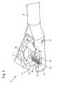
- the illustration Fig. 1shows a perspective view of a medical cutting instrument 1 for cutting muscles and tendons.
- This trained as a biceps tendon punch and suitable for both open surgery and for arthroscopic surgery cutting instrument 1has a shaft 2, at the distal end of a two jaw parts 3 and 4 existing tool 5 is arranged, wherein a jaw part 3 is rigid and the other jaw part 4 as a pivot axis 6 relative to the rigid jaw part 3 pivotable jaw part 4 is formed is.
- a handle 7is arranged, which consists in the illustrated embodiment of two handle parts 8 and 9, wherein a handle part 8 is rigid and the other handle part 9 as about a pivot axis 10 relative to the rigid handle part 8 pivotable handle part. 9 is trained.
- the pivotable jaw part 4 of the tool 5 and the pivotable handle part 9 of the handle 7are in operative connection with one another via an actuating element 11 mounted in the shaft 2 in such a way that the pivotable jaw part 4 is actuated by actuating the pivotable grip part 9 between a closed position (FIG. Fig. 4 . 6 and 7 ) and a relative to the rigid jaw part 3 pivoted open position ( Fig. 1 to 3 ) is adjustable.
- a particularly advantageous guidance and thus positioning of the tendoncan be achieved when cutting, resulting in the subcutaneous application of the instrument according to the invention to a much better cutting result.
- the illustrated pivoting of the jaw part 4 relative to the other jaw part 3is only one embodiment for mutual adjustment of the jaw parts 3 and 4 to each other.
- the construction of the distal-side tool 5 consisting of the parts 3 and 4is particularly the enlarged detail views of the figures Fig. 2 to 4 as well as 6 and 7.
- the peculiarity of the illustrated tools 5is that these tools 5 are designed to simultaneously sever and hold one end of the severed muscle / tendon tissue 12. In this way, the severed muscle / tendon tissue 12 can be prevented from retracting to the neck after severing if the muscle / tendon tissue 12 has not previously been secured, for example, by arthroscopic suturing.
- clamping-cutting double functionon the one hand on the rigid jaw part 3 and the pivotable jaw part 4 mutually corresponding clamping surfaces 14 are arranged and on the other hand at least on the pivotable jaw part 4, a cutting edge 15 is formed.
- the clamping surfaces 14are formed in these embodiments as transverse to the instrument longitudinal axis 16 aligned teeth 17.
- the meshing of the teeth 17ensures a secure and non-slip grip of the arranged between the clamping surfaces 14 muscle / tendon tissue 12th
- the cutting edge 15is oriented downwards towards the rigid jaw part 3 so that it is arranged at the distal end of the pivotable jaw part 4 that the muscle / tendon tissue 12 arranged in the guides 13 of the jaw parts 3 and 4 is severed as soon as the pivotable jaw part 4 of the tool 5 is completely closed.
- a recess 18 formed as an opening 18 for receiving the cutting edge 15is arranged in the rigid jaw part 3.
- This recess 18 in the rigid jaw part 3 of the tool 5ensures that the pivotable jaw part 4 of the tool 5 can be completely closed and not stopped by the start of the cutting edge 15 against the rigid jaw part 3 becomes.
- the recess 18it is of course also possible to form the recess 18 as a non-open recess in the rigid jaw part 3.
- clamping surfaces 14on the jaws 3 and 4 results from a synopsis of the figures Fig. 2 and 3 according to which the clamping surface 14 is arranged on the pivotable jaw part 4 proximally behind the cutting edge 15 and the clamping surface 14 is arranged on the rigid jaw part 3 proximally behind the recess 18.
- the illustration Fig. 4shows a second, alternative embodiment for forming the tool 5.
- the distal end 19 of the rigid jaw part 3, which projects beyond the pivotable jaw part 4 in the axial direction,is rounded in order to facilitate penetration of the medical cutting instrument 1 through soft parts by the dilator-shaped configuration of the distal instrument tip.
- the illustration Fig. 5shows an alternative embodiment for the formation of the clamping surfaces 14.
- the clamping surfaces 14are formed as by transverse and longitudinal recesses 20 separate individual teeth 21.
- the formation as individual teeth 21ensures a secure fit and a good lateral slip resistance for the severed muscle or tendon tissue 12th
- the formed on the clamping surfaces 14 transversely oriented teeth 17 and the individual teeth 21are advantageously formed distally inclined to ensure that a better wedging and holding the severed muscle or tendon tissue 12 is achieved. Due to the inclination to the distal muscle or tendon tissue 12, which wants to retract to the proximal, pressed against the teeth 17 and the individual teeth 21.
- the pictures 6 and 7show an alternative embodiment for forming the clamping surfaces 14.
- a lever mechanism 22is provided for adjusting and adjusting the depth of cut on the handle 7, which forms a variable stop for closing the two jaws 3 and 4 against each other and thus causes the adjustment of the cutting depth.
- an externally readable scale 23is provided on the handle 7, so that the muscle / tendon tissue can be cut through the operation of the lever mechanism 22 targeted at a certain depth.
- the above-described medical cutting tool 1as a combined cutting and holding tool, it is possible to clampingly hold one end of the muscle or tendon tissue 12 severed in the first working incision with the same cutting instrument 1, thus preventing it from retracting and ready for further operative use hold.
Landscapes
- Health & Medical Sciences (AREA)
- Surgery (AREA)
- Life Sciences & Earth Sciences (AREA)
- Medical Informatics (AREA)
- Animal Behavior & Ethology (AREA)
- Engineering & Computer Science (AREA)
- Biomedical Technology (AREA)
- Heart & Thoracic Surgery (AREA)
- Veterinary Medicine (AREA)
- Molecular Biology (AREA)
- Nuclear Medicine, Radiotherapy & Molecular Imaging (AREA)
- General Health & Medical Sciences (AREA)
- Public Health (AREA)
- Orthopedic Medicine & Surgery (AREA)
- Rheumatology (AREA)
- Ophthalmology & Optometry (AREA)
- Surgical Instruments (AREA)
Description
Translated fromGermanDie Erfindung betrifft ein medizinisches Schneidinstrument zum Schneiden von Muskeln und Sehnen, mit einem Schaft, an dessen distalem Ende ein aus zwei Maulteilen bestehendes Werkzeug angeordnet ist, wobei wenigstens ein Maulteil als gegenüber dem anderen Maulteil verstellbares Maulteil ausgebildet ist, und an dessen proximalem Ende eine Handhabe angeordnet ist, wobei das verstellbare Maulteil und die Handhabe über ein im Schaft gelagertes Betätigungselement derart in Wirkverbindung miteinander stehen, dass das verstellbare Maulteil durch Betätigen der Handhabe zwischen einer geschlossenen Position und einer geöffneten Position des Werkzeuges verstellbar ist und wobei das Werkzeug zum gleichzeitigen Durchtrennen und Halten eines Endes des durchtrennten Muskel-/Sehnengewebes ausgebildet ist.The invention relates to a medical cutting instrument for cutting muscles and tendons, comprising a shaft, at the distal end of which a tool consisting of two jaw parts is arranged, wherein at least one jaw part is designed as a jaw part which is adjustable relative to the other jaw part, and at its proximal end Handle is arranged, wherein the adjustable jaw part and the handle are operatively connected to each other via an actuating element mounted in the shaft such that the adjustable jaw part is adjustable by operating the handle between a closed position and an open position of the tool and wherein the tool for simultaneous severing and holding one end of the severed muscle / tendon tissue.
Gattungsgemäße medizinische Schneidinstrumente werden beispielsweise bei der Bizepstenotomie- oder Bizepstenodese-Operation verwendet, um die Bizepssehne zu durchtrennen, wenn diese aufgrund von Abnutzung Schmerzen im Gelenk hervorruft.Generic medical cutting instruments are used, for example, in bicepsotomy or bicepstenodosis surgery to sever the biceps tendon when it causes pain in the joint due to wear.
Aus der
Ein weiteres medizinisches Schneidinstrument zum Schneiden von Muskeln und Sehnen ist beispielsweise aus dem US-Patent
Im Gegensatz zur offenen Chirurgie, bei der die Sehne blind abgeschnitten wird, da man den Situs nicht eröffnen will, ist die Sehne bei der Arthroskopie zwar sichtbar, muss aber vor dem Durchtrennen zunächst durch Anschlingen und arthroskopisches Nähen gesichert werden, um zu verhindern, dass sich die Sehne nach dem Durchtrennen sofort zum Ansatz zurückzieht und dann mittels offener Chirurgie wieder geborgen werden muss.In contrast to open surgery, in which the tendon is cut off blindly, since one does not want to open the site, the tendon is visible in the arthroscopy, but must first be secured by transection and arthroscopic suturing before cutting, in order to prevent the tendon immediately retracts to the neck after severing and then has to be recovered by open surgery.
Davon ausgehend liegt der Erfindung dieAufgabe zugrunde, ein medizinisches Schneidinstrument der eingangs genannten Art zu schaffen, das bei einfacher Handhabung ein kontrolliertes Durchtrennen des Muskel-/Sehnengewebes ermöglicht.On this basis, the invention is based on theobject to provide a medical cutting instrument of the aforementioned kind that allows a controlled severing of the muscle / tendon tissue with simple handling.
DieLösung dieser Aufgabenstellung ist erfindungsgemäß gekennzeichnet durch die Merkmale des Anspruchs 1 gegeben. Hierbei ist zumindest im anderen Maulteil eine Führung zur führenden Aufnahme des zu durchtrennenden Muskel-/Sehnengewebes ausgebildet.Thesolution to thisproblem is inventively characterized by the features of
Vorteilhafte Weiterbildungen der Erfindung sind Gegenstand der Unteransprüche.Advantageous developments of the invention are the subject of the dependent claims.
Durch die Ausgestaltung des Werkzeugs als kombiniertes Schneid- und Haltewerkzeug ist es möglich, ein Ende des im ersten Arbeitsschritt mit demselben Instrument durchtrennten Muskel- oder Sehnengewebes klemmend festzuhalten und so am Zurückziehen zu hindern.The design of the tool as a combined cutting and holding tool, it is possible to clamp one end of the severed in the first step with the same instrument muscle or tendon tissue and thus prevent it from being pulled back.
Um sicherzustellen, dass das zu durchtrennende Muskel-/Sehnengewebe richtig zur Schneidkante und zu den Klemmflächen ausgerichtet ist, sind zumindest im anderen Maulteil, vorzugsweise in beiden Maulteilen, Führungen zur führenden Aufnahme des zu durchtrennenden Muskel-/Sehnengewebes ausgebildet.To ensure that the muscle / tendon tissue to be cut is properly aligned with the cutting edge and the clamping surfaces are at least in other jaw part, preferably in both jaw parts, guides for leading receiving the muscle / tendon tissue to be cut.
Gemäß der Erfindung wird vorgeschlagen, dass zum Halten des durchtrennten Muskel- oder Sehnengewebes am beiden Maulteilen miteinander korrespondierende Klemmflächen angeordnet sind, wobei die Klemmflächen vorzugsweise als quer zur Instrumentenlängsachse ausgerichtete ineinander greifende Verzahnungen ausgebildet sind.According to the invention it is proposed that for holding the severed muscle or tendon tissue on the two jaw parts corresponding clamping surfaces are arranged, wherein the clamping surfaces are preferably formed as transversely aligned to the instrument longitudinal axis interlocking teeth.
Mit einer alternativen Ausführungsform der Erfindung wird vorgeschlagen, dass die Klemmflächen als durch Quer- und Längsvertiefungen voneinander getrennte Einzelzähne ausgebildet sind. Die Ausbildung als Einzelzähne gewährt einen sicheren Halt und eine gute seitliche Verrutschsicherheit für das durchtrennte Muskel- oder Sehnengewebe.With an alternative embodiment of the invention, it is proposed that the clamping surfaces are formed as individual teeth separated by transverse and longitudinal depressions. The training as single teeth provides a secure fit and a good lateral slipping for the severed muscle or tendon tissue.
Weiterhin wird mit der Erfindung vorgeschlagen, dass die auf den Klemmflächen ausgebildete quer ausgerichtete Verzahnung bzw. die Einzelzähne zumindest anteilig nach distal geneigt ausgebildet sind, um sicherzustellen, dass ein besseres Verkeilen und Festhalten des durchtrennten Muskel- oder Sehnengewebes erreicht wird, da durch die Neigung nach distal das Gewebe, das sich nach proximal zurückziehen will, fester gegen die Verzahnung bzw. die Einzelzähne gepresst wird. Diese Wirkung wird zunehmender Anzahl der geneigten Verzahnungen bzw. Einzelzähne der Klemmflächen verstärkt.Furthermore, it is proposed with the invention that the formed on the clamping surfaces transversely oriented teeth or the individual teeth are at least partially formed distally inclined to ensure that a better wedging and holding the severed muscle or tendon tissue is achieved because of the inclination distal to the tissue, which wants to retract to the proximal, is pressed firmly against the teeth or the individual teeth. This effect is increased as the number of inclined teeth or individual teeth of the clamping surfaces.
Weiterhin wird mit der Erfindung vorgeschlagen, die Klemmflächen als am starren Maulteil angeordneter solitärer Einzelzahn und als am verschwenkbaren Maulteil entlang der Ausnehmung verlaufende Zahnreihe ausgebildet ist.Furthermore, it is proposed with the invention, the clamping surfaces as arranged on the rigid jaw member solitary single tooth and as the pivotable jaw part along the recess extending row of teeth is formed.
Zum Ausbilden der Schneidfunktion ist zumindest am verstellbaren Maulteil eine Schneidkante ausgebildet, die nach unten zum anderen Maulteil hin ausgerichtet am distalen Ende des verstellbaren Maulteils angeordnet ist.To form the cutting function, a cutting edge is formed at least on the adjustable jaw part, which is arranged down to the other jaw part aligned at the distal end of the adjustable jaw part.
Mit einer alternativen Ausführungsform der Erfindung wird vorgeschlagen, dass die Schneidkante nach unten zum anderen Maulteil hin ausgerichtet U-förmig ausgebildet so am verstellbaren Maulteil angeordnet ist, dass sich die Schneidkante vom distalen Ende des verstellbaren Maulteils zu beiden Seitenbereichen des verstellbaren Maulteils erstreckt. Diese Ausgestaltung der Schneidkante hat den Vorteil, dass gerade bei schwierigen Schneidsituationen, beispielsweise durch ungewöhnlich dicke Sehnen oder durch die Sehnenscheide, ein sicheres Schneidergebnis erzielbar ist.With an alternative embodiment of the invention, it is proposed that the cutting edge is designed to be U-shaped downwards relative to the other jaw part, so that the cutting edge extends from the distal end of the adjustable jaw part to both side regions of the adjustable jaw part. This embodiment of the cutting edge has the advantage that, especially in difficult cutting situations, for example by unusually thick tendons or by the tendon sheath, a secure cutting result can be achieved.
Um ein präzises und vollständiges Durchtrennen des Muskel- oder Sehnengewebes beim Schließen des verstellbaren Maulteils zu gewährleisten, wird mit der Erfindung vorgeschlagen, dass im Bereich der am verstellbaren Maulteil angeordneten Schneidkante im anderen Maulteil eine Aussparung zur Aufnahme der Schneidkante ausgebildet ist, die beispielsweise als Vertiefung oder durchgehende Öffnung im starren Maulteil ausgebildet ist.In order to ensure a precise and complete severing of the muscle or tendon tissue when closing the adjustable jaw part, it is proposed with the invention that in the region of the arranged on the adjustable jaw cutting edge in the other jaw part a recess for receiving the cutting edge is formed, for example, as a recess or through opening in the rigid jaw part is formed.
Weiterhin wird mit der Erfindung vorgeschlagen, dass die Klemmfläche am verstellbaren Maulteil proximal hinter der Schneidkante angeordnet ist und/oder die Klemmfläche am anderen Maulteil proximal hinter der Aussparung zur Aufnahme der Schneidkante angeordnet ist, um ein Ende des durchtrennten Gewebes direkt nach dem Durchtrennen klemmend fixieren zu können.Furthermore, it is proposed with the invention that the clamping surface is arranged on the adjustable jaw part proximally behind the cutting edge and / or the clamping surface is arranged on the other jaw part proximally behind the recess for receiving the cutting edge to fix an end of the severed tissue directly after cutting by clamping to be able to.
Schließlich wird mit der Erfindung vorgeschlagen, dass das distale Ende des anderen Maulteils, das das verstellbare Maulteil in axialer Richtung überragt, abgerundet ausgebildet ist, um durch die dilatatorförmige Ausgestaltung der distalen Instrumentenspitze das Eindringen des medizinischen Schneidinstruments durch Weichteile zu erleichtern.Finally, it is proposed with the invention that the distal end of the other jaw part, which projects beyond the adjustable jaw part in the axial direction, is rounded in order to facilitate the penetration of the medical cutting instrument through soft tissue through the dilator-shaped configuration of the distal instrument tip.
Zur Einstellung und Verstellung der Schneidtiefe wird mit der Erfindung vorgeschlagen, dass im Bereich der Handhabe ein Hebelmechanismus vorgesehen ist, der einen variablen Anschlag für das Schließen der beiden Maulteile gegeneinander ausbildet und so die Verstellung der Schneidtiefe bewirkt.For adjusting and adjusting the cutting depth is proposed by the invention that in the region of the handle, a lever mechanism is provided which forms a variable stop for closing the two jaws against each other and thus causes the adjustment of the cutting depth.
Weiterhin wird mit der Erfindung vorgeschlagen, dass an der Handhabe eine Skalierung angeordnet ist, um das Muskel-/Sehnengewebe gezielt in einer bestimmten Tiefe durchtrennen zu können.Furthermore, it is proposed with the invention that a scaling is arranged on the handle in order to be able to cut through the muscle / tendon tissue at a specific depth in a targeted manner.
Weitere Merkmale und Vorteile der Erfindung ergeben sich anhand der zugehörigen Zeichnungen, in denen vier Ausführungsbeispiele eines erfindungsgemäßen medizinischen Schneidinstruments zum Schneiden von Muskeln und Sehnen nur beispielhaft dargestellt sind, ohne die Erfindung auf diese Ausführungsbeispiele zu beschränken. In den Zeichnungen zeigt:
- Fig. 1
- eine schematische Seitenansicht einer ersten Ausführungsform eines erfindungsgemäßen medizinischen Schneidinstruments zum Schneiden von Muskeln und Sehnen;
- Fig. 2
- eine vergrößerte perspektivische Draufsicht auf das Detail II gemäß
Fig. 2 ; - Fig. 3
- eine Ansicht von unten der Darstellung gemäß
Fig. 2 ; - Fig. 4
- eine Ansicht gemäß
Fig. 2 , jedoch die geschlossene Position einer zweiten erfindungsgemäßen Ausführungsform darstellend; - Fig. 5
- eine perspektivische Ansicht einer Klemmfläche gemäß einer dritten erfindungsgemäßen Ausführungsform;
- Fig. 6
- eine perspektivische Vorderansicht eines Werkzeugs gemäß einer vierten erfindungsgemäßen Ausführungsform und
- Fig. 7
- eine perspektivische Rückansicht des Werkzeugs gemäß
Fig. 6 .
- Fig. 1
- a schematic side view of a first embodiment of a medical cutting instrument according to the invention for cutting muscles and tendons;
- Fig. 2
- an enlarged perspective top view of the detail II according to
Fig. 2 ; - Fig. 3
- a view from below the representation according to
Fig. 2 ; - Fig. 4
- a view according to
Fig. 2 but showing the closed position of a second embodiment of the invention; - Fig. 5
- a perspective view of a clamping surface according to a third embodiment of the invention;
- Fig. 6
- a front perspective view of a tool according to a fourth embodiment of the invention and
- Fig. 7
- a perspective rear view of the tool according to
Fig. 6 ,
Die Abbildung
Dieses beispielsweise als Bizepssehnenstanze ausgebildete und sowohl für die offene Chirurgie als auch für die arthroskopische Chirurgie verwendbare Schneidinstrument 1 weist einen Schaft 2 auf, an dessen distalem Ende ein aus zwei Maulteilen 3 und 4 bestehendes Werkzeug 5 angeordnet ist, wobei ein Maulteil 3 starr ausgebildet ist und das andere Maulteil 4 als um eine Schwenkachse 6 gegenüber dem starren Maulteil 3 verschwenkbares Maulteil 4 ausgebildet ist. Am proximalem Ende des Schaftes 2 ist eine Handhabe 7 angeordnet, die bei der dargestellten Ausführungsform aus zwei Griffteilen 8 und 9 besteht, wobei ein Griffteil 8 starr ausgebildet ist und das andere Griffteil 9 als um eine Schwenkachse 10 gegenüber dem starren Griffteil 8 verschwenkbares Griffteil 9 ausgebildet ist.This trained as a biceps tendon punch and suitable for both open surgery and for arthroscopic
Das verschwenkbare Maulteil 4 des Werkzeugs 5 und das verschwenkbare Griffteil 9 der Handhabe 7 stehen über ein im Schaft 2 gelagertes Betätigungselement 11 derart in Wirkverbindung miteinander, dass das verschwenkbare Maulteil 4 durch Betätigen des verschwenkbaren Griffteils 9 zwischen einer am starren Maulteil 3 anliegenden geschlossenen Position (
Alternativ zu der dargestellten Ausführungsform des Schneidinstruments 1 mit einem starren Maulteil 3 und einem verschwenkbaren Maulteil 4 ist es selbstverständlich auch möglich, beide Maulteile verschwenkbar auszugestalten. Gerade für freischwebende, freipräparierbare Sehnen erweist sich eine Variante mit zwei verschwenkbaren Maulteilen als besonders sinnvoll.As an alternative to the illustrated embodiment of the cutting
Weiterhin ist das dargestellte Verschwenken des Maulteils 4 gegenüber dem anderen Maulteil 3 nur eine Ausführungsform zum gegenseitigen Verstellen der Maulteile 3 und 4 zueinander. Neben dem Verschwenken um die Schwenkachse 6 ist es beispielsweise auch möglich, die Maulteile 3 und 4 axial gegeneinander zu verschieben.Furthermore, the illustrated pivoting of the
Der Aufbau des aus den Mauteilen 3 und 4 bestehenden distalseitigen Werkzeugs 5 ist insbesondere den vergrößerten Detailansichten der Abbildungen
Zur führenden Aufnahme des zu schneidenden Muskel-/Sehnengewebes 12 (
Die Besonderheit der dargestellten Werkzeuge 5 ist, dass diese Werkzeuge 5 zum gleichzeitigen Durchtrennen und Halten eines Endes des durchtrennten Muskel-/Sehnengewebes 12 ausgebildet ist. Auf dieses Weise kann verhindert werden, dass sich das durchtrennte Muskel-/Sehnengewebe 12 nach dem Durchtrennen zum Ansatz hin zurückzieht, wenn das Muskel-/Sehnengewebe 12 nicht zuvor, beispielsweise durch arthroskopisches Nähen, gesichert wurde.The peculiarity of the illustrated
Zur Ausbildung dieser Klemm-Schneid-Doppelfunktion sind einerseits am starren Maulteil 3 und am verschwenkbaren Maulteil 4 miteinander korrespondierende Klemmflächen 14 angeordnet und ist andererseits zumindest am verschwenkbaren Maulteil 4 eine Schneidkante 15 ausgebildet. Die Klemmflächen 14 sind bei diesen Ausführungsformen als quer zur Instrumentenlängsachse 16 ausgerichtete Verzahnungen 17 ausgebildet sind. Das Ineinandergreifen der Verzahnungen 17 gewährleistet einen sicheren und rutschfesten Halt des zwischen den Klemmflächen 14 angeordneten Muskel-/Sehnengewebe 12.To form this clamping-cutting double function on the one hand on the
Die Schneidkante 15 ist nach unten zum starren Maulteil 3 hin ausgerichtet so am distalen Ende des verschwenkbaren Maulteils 4 angeordnet, dass das in den Führungen 13 der Maulteile 3 und 4 angeordnete Muskel-/Sehnengewebe 12 durchtrennt wird, sobald das verschwenkbare Maulteil 4 des Werkzeugs 5 vollständig geschlossen wird. Um weiterhin sicher zu stellen, dass nach dem Durchtrennen des Muskel-/Sehnengewebes 12 mittels der Schneidkante 15 das im proximalen Teil des Werkzeugs 5 befindliche Ende des durchtrennten Muskel-/Sehnengewebes 12 sicher von den miteinander korrespondierende Klemmflächen 14 der Maulteile 3 und 4 gehalten wird, ist im Bereich der am verschwenkbaren Maulteil 4 angeordneten Schneidkante 15 im starren Maulteil 3 eine als Öffnung 18 ausgebildete Aussparung 18 zur Aufnahme der Schneidkante 15 angeordnet.The
Diese Aussparung 18 im starren Maulteil 3 des Werkzeugs 5 stellt sicher, dass das verschwenkbare Maulteil 4 des Werkzeugs 5 vollständig geschlossen werden kann und nicht durch das Anlaufen der Scheidkante 15 gegen das starre Maulteil 3 gestoppt wird. Alternativ zur Ausbildung der Aussparung 18 als durchgehende Öffnung 18 ist es selbstverständlich auch möglich, die Aussparung 18 als nicht offene Vertiefung im starren Maulteil 3 auszubilden.This
Die Platzierung der Klemmflächen 14 an den Maulteilen 3 und 4 ergibt sich aus einer Zusammenschau der Abbildungen
Die Abbildung
Bei dieser alternativen Ausführungsform ist zusätzlich das distale Ende 19 des starren Maulteils 3, das das verschwenkbare Maulteil 4 in axialer Richtung überragt, abgerundet ausgebildet ist, um durch die dilatatorförmige Ausgestaltung der distalen Instrumentenspitze das Eindringen des medizinischen Schneidinstruments 1 durch Weichteile zu erleichtern.In this alternative embodiment, in addition, the
Die Abbildung
Die auf den Klemmflächen 14 ausgebildete quer ausgerichtete Verzahnung 17 bzw. die Einzelzähne 21 sind vorteilhafterweise nach distal geneigt ausgebildet, um sicherzustellen, dass ein besseres Verkeilen und Festhalten des durchtrennten Muskel- oder Sehnengewebes 12 erreicht wird. Durch die Neigung nach distal wird das Muskel- oder Sehnengewebe 12, das sich nach proximal zurückziehen will, fester gegen die Verzahnung 17 bzw. die Einzelzähne 21 gepresst.The formed on the clamping surfaces 14 transversely oriented
Die Abbildungen
Der vorzugsweise im Wesentlichen mittig am starren Maulteil 3 angeordnete solitäre Einzelzahn 24 presst das zu haltende Muskel-/Sehnengewebe 12 in der geschlossenen Position der Maulteile 3 und 4 gegen die Zahnreihe 25 des verschwenkbaren Maulteils 4 und gewährleistet so den sicheren Halt des durchtrennten Muskel-/Sehnengewebes 12.The solitary
Wie weiterhin aus
Weiterhin ist an der Handhabe 7 eine von außen ablesbare Skalierung 23 vorgesehen, damit das Muskel-/Sehnengewebe durch die Betätigung des Hebelmechanismus 22 gezielt in einer bestimmten Tiefe durchtrennt werden kann.Furthermore, an externally
Durch die Ausgestaltung des voranstehen beschriebenen medizinischen Schneidwerkzeugs 1 als kombiniertes Schneid- und Haltewerkzeug ist es möglich, ein Ende des im ersten Arbeitsschnitt mit demselben Schneidinstrument 1 durchtrennten Muskel- oder Sehnengewebes 12 klemmend festzuhalten und so am Zurückziehen zu hindern und zur weiteren operativen Verwendung bereit zu halten.
Claims (13)
- Medical cutting instrument for cutting muscles and tendons, with a shaft (2) on the distal end of which a tool (5) consisting of two jaw parts (3, 4) is disposed, wherein at least a first jaw part (4) is formed as a first jaw part (4) movable relative to the other, second jaw part (3), and at the proximal end thereof a handle (7) is disposed, wherein the movable first jaw part (4) and the handle (7) are operatively connected with one another over an actuation element (11) mounted in a shaft (2) in such a manner that the first, movable jaw part (4) can be moved between a closed position and an open position of the tool (5) by actuating the handle (7), and wherein the tool (5) is designed for simultaneously cutting and holding an end of the severed muscle/ tendon tissue (12), wherein at least on the movable first jaw part (4) a cutting edge (15) aligned with the second jaw part (3) and located on the distal end of the movable first jaw part (4) is formed and clamping surfaces (14) corresponding to one another are disposed on the two jaw parts (3, 4),characterized in that at least in the second jaw part (3) a guideway (13) is formed for accommodating and guiding the muscle/tendon tissue (12) to be cut, which is suitable for aligning the muscle/tendon to be cut with the cutting edge (15) and the clamping surfaces (14).
- Medical cutting instrument according to claim 1,characterized in that the guideway (13) is formed in both jaw parts (3, 4).
- Medical cutting instrument according to claim 1 or 2,characterized in that the clamping surfaces (14) are formed as tooth systems (17) aligned perpendicularly with the longitudinal axis (16) of the instrument.
- Medical cutting instrument according to claim 1 or 2,characterized in that the clamping surfaces (14) are formed as individual teeth (21) separated from one another by transverse and longitudinal indentations (20).
- Medical cutting instrument according to claim 3 or 4,characterized in that the transversely aligned clamping tooth system (17) and/or the individual teeth (21) are formed to be at least partially inclined distally.
- Medical cutting instrument according to claim 1,characterized in that the clamping surfaces (14) are formed as a solitary single tooth (24) disposed on the rigid jaw part (3) and as a row of teeth (25) running on the pivotable part of the jaw (4) along the recess (13).
- Medical cutting instrument according to one of claims 1 to 6,characterized in that the cutting edge (15) is disposed on the movable jaw part (4) in U-shaped alignment relative to the other jaw part (3) extending from the distal end of the movable jaw part (4) toward both side areas of the movable jaw part (4).
- Medical cutting instrument according to one of claims 1 to 6,characterized in that in the area of the cutting edge (15) disposed on the movable jaw part (4), a hollow (18) is formed in the other jaw part (3) to receive the cutting edge (15).
- Medical cutting instrument according to claim 8,characterized in that the hollow (18) is formed as an indentation or a penetrating opening (18).
- Medical cutting instrument according to claim 8 or 9,characterized in that the clamping surface (14) is disposed on the movable jaw part (4) proximally behind the cutting edge (15) and/or the clamping surface (14) is disposed on the other jaw part (3) proximally behind the hollow (18).
- Medical cutting instrument according to one of claims 1 to 10,characterized in that the distal end (19) of the other jaw part (3), which projects beyond the movable jaw part (4) in the axial direction, is made to be rounded.
- Medical cutting instrument according to one of claims 1 to 11,characterized in that in the area of the handle (7) a lever mechanism (22) is disposed, which forms a variable stop for the closing of the jaw parts (3 and 4) against one another and thus makes it possible to adjust the cutting depth.
- Medical cutting instrument according to claim 12,characterized in that a scale (23) is disposed on the handle (7) for determining the cutting depth.
Applications Claiming Priority (1)
| Application Number | Priority Date | Filing Date | Title |
|---|---|---|---|
| DE102011107178ADE102011107178A1 (en) | 2011-07-13 | 2011-07-13 | Medical cutting instrument for cutting muscles and tendons |
Publications (3)
| Publication Number | Publication Date |
|---|---|
| EP2545857A2 EP2545857A2 (en) | 2013-01-16 |
| EP2545857A3 EP2545857A3 (en) | 2013-08-28 |
| EP2545857B1true EP2545857B1 (en) | 2014-12-31 |
Family
ID=46578795
Family Applications (1)
| Application Number | Title | Priority Date | Filing Date |
|---|---|---|---|
| EP12005050.5AActiveEP2545857B1 (en) | 2011-07-13 | 2012-07-07 | Medical cutting instrument for cutting muscles and tendons |
Country Status (3)
| Country | Link |
|---|---|
| US (1) | US9427246B2 (en) |
| EP (1) | EP2545857B1 (en) |
| DE (1) | DE102011107178A1 (en) |
Families Citing this family (5)
| Publication number | Priority date | Publication date | Assignee | Title |
|---|---|---|---|---|
| JP6224503B2 (en)* | 2014-04-02 | 2017-11-01 | 株式会社ソニー・インタラクティブエンタテインメント | Information processing apparatus, information processing system, and content image generation method |
| US10631888B2 (en)* | 2014-04-28 | 2020-04-28 | Emory University | Systems and methods for tissue treatment |
| WO2020223579A1 (en)* | 2019-05-01 | 2020-11-05 | Cha Bibianna | Inline cutter for cutting and retrieving implanted microsurgical devices |
| WO2021144783A2 (en)* | 2020-06-12 | 2021-07-22 | Inno4Spine Ag | Rongeur for tissue removal |
| EP4601565A2 (en)* | 2022-10-14 | 2025-08-20 | T.A.G. Medical Products Corporation Ltd. | Devices and methods for cutting a tendon in proximity to a biceps |
Family Cites Families (82)
| Publication number | Priority date | Publication date | Assignee | Title |
|---|---|---|---|---|
| US253359A (en) | 1882-02-07 | Hog-tendon cutter | ||
| US865551A (en)* | 1906-11-30 | 1907-09-10 | Frederick P Wells | Veterinary dental instrument. |
| US1079128A (en)* | 1913-02-20 | 1913-11-18 | Clarence O S Howe | Surgical instrument. |
| US2706987A (en)* | 1952-09-12 | 1955-04-26 | Harold F Bramstedt | Insert for surgical needle clamp |
| US3006344A (en)* | 1959-02-24 | 1961-10-31 | Isaac J Vogelfanger | Surgical ligator and cutter |
| US3391690A (en)* | 1965-04-05 | 1968-07-09 | Armao Thomas Anthony | Biopsy instrument including tissue heating or cooling means and method of use |
| US3404677A (en)* | 1965-07-08 | 1968-10-08 | Henry A. Springer | Biopsy and tissue removing device |
| US3631858A (en)* | 1969-07-14 | 1972-01-04 | Robert A Ersek | Sever cord |
| US3763860A (en)* | 1971-08-26 | 1973-10-09 | H Clarke | Laparoscopy instruments and method for suturing and ligation |
| US4243047A (en)* | 1979-02-07 | 1981-01-06 | Auburn Enterprises, Inc. | Instrument for taking tissue specimens |
| US4522206A (en)* | 1983-01-26 | 1985-06-11 | Dyonics, Inc. | Surgical instrument |
| DE3303349A1 (en)* | 1983-02-02 | 1984-08-02 | Reinhold 7230 Schramberg Straub | SURGICAL INSTRUMENT FOR CUTTING TISSUE IN PARTICULAR CARTILAGE |
| US4597385A (en)* | 1983-04-29 | 1986-07-01 | Watson Trevor F | Biopsy instrument |
| US4919152A (en)* | 1987-03-02 | 1990-04-24 | Ralph Ger | Method of closing the opening of a hernial sac |
| CH662263A5 (en)* | 1983-09-13 | 1987-09-30 | Gegauf Fritz Ag | HYSTERECTOMIUM. |
| IL73079A (en)* | 1984-09-26 | 1989-01-31 | Porat Michael | Gripper means for medical instruments |
| US4763669A (en)* | 1986-01-09 | 1988-08-16 | Jaeger John C | Surgical instrument with adjustable angle of operation |
| US4971067A (en)* | 1988-05-05 | 1990-11-20 | Lee Bolduc | Biopsy instrument with a disposable cutting blade |
| DE3824910C2 (en)* | 1988-07-22 | 1994-06-09 | Wolf Gmbh Richard | Arthroscopy hook punch |
| US4955897A (en)* | 1988-08-22 | 1990-09-11 | Ship Arthur G | Tissue forceps |
| IN177831B (en)* | 1989-07-13 | 1997-02-22 | Nat Res Dev | |
| US5282484A (en)* | 1989-08-18 | 1994-02-01 | Endovascular Instruments, Inc. | Method for performing a partial atherectomy |
| US5071424A (en)* | 1989-08-18 | 1991-12-10 | Evi Corporation | Catheter atherotome |
| US5984938A (en)* | 1989-12-05 | 1999-11-16 | Yoon; Inbae | Surgical instrument with jaws and movable internal scissors and method for use thereof |
| DE9001262U1 (en)* | 1990-02-05 | 1990-08-09 | Martin, Werner, 7207 Rietheim-Weilheim | Surgical needle holder for an endo-suture, endo-ligature or similar. |
| US5234453A (en)* | 1990-05-10 | 1993-08-10 | Symblosis Corporation | Cobalt base alloy end effectors for laparoscopic surgical scissors |
| US5260415A (en)* | 1990-06-04 | 1993-11-09 | E. I. Du Pont De Nemours And Company | Crosslinking of polymers containing diaryl ketones |
| US5217460A (en)* | 1991-03-22 | 1993-06-08 | Knoepfler Dennis J | Multiple purpose forceps |
| US5174300A (en)* | 1991-04-04 | 1992-12-29 | Symbiosis Corporation | Endoscopic surgical instruments having rotatable end effectors |
| US5395375A (en)* | 1992-11-18 | 1995-03-07 | Symbiosis Corporation | Arthroscopic surgical instruments |
| US5286255A (en)* | 1991-07-29 | 1994-02-15 | Linvatec Corporation | Surgical forceps |
| US5254129A (en)* | 1991-11-22 | 1993-10-19 | Alexander Chris B | Arthroscopic resector |
| US6974453B2 (en)* | 1993-05-10 | 2005-12-13 | Arthrocare Corporation | Dual mode electrosurgical clamping probe and related methods |
| US5383471A (en)* | 1992-04-10 | 1995-01-24 | Funnell; David M. | Surgical biopsy instrument |
| US5368606A (en)* | 1992-07-02 | 1994-11-29 | Marlow Surgical Technologies, Inc. | Endoscopic instrument system |
| US5304203A (en)* | 1992-10-20 | 1994-04-19 | Numed Technologies, Inc. | Tissue extracting forceps for laparoscopic surgery |
| US5389104A (en)* | 1992-11-18 | 1995-02-14 | Symbiosis Corporation | Arthroscopic surgical instruments |
| US5683359A (en)* | 1992-11-18 | 1997-11-04 | Symbiosis Corporation | Arthroscopic surgical instruments having suction capability |
| CA2114330A1 (en)* | 1993-01-29 | 1994-07-30 | Smith & Nephew Endoscopy, Inc. | Rotatable curved instrument |
| US5417701A (en)* | 1993-03-30 | 1995-05-23 | Holmed Corporation | Surgical instrument with magnetic needle holder |
| US5431674A (en)* | 1993-09-07 | 1995-07-11 | Pa Consulting Group | Compound motion cutting device |
| DE4400409A1 (en)* | 1994-01-05 | 1995-07-06 | Hein Kleihues | Microsurgical instrument |
| US5439471A (en)* | 1994-01-05 | 1995-08-08 | Kerr; Harry D. | Combined surgical needle holder and scissors |
| US5484447A (en)* | 1994-07-26 | 1996-01-16 | Duckworth & Kent Limited | Calipers for use in ophthalmic surgery |
| US5531756A (en)* | 1994-08-02 | 1996-07-02 | Larose; Daniel J. | Arthroscopic surgical punch |
| CA2159685C (en)* | 1994-10-07 | 2007-07-31 | Scott W. Larsen | Endoscopic surgical instruments useful for spinal procedures |
| US5643307A (en)* | 1994-12-13 | 1997-07-01 | Symbiosis Corporation | Colposcopic biopsy punch with removable multiple sample basket |
| US5569299A (en)* | 1995-03-01 | 1996-10-29 | Symbiosis Corporation | Endoscopic urological biopsy forceps |
| US6077280A (en)* | 1995-06-29 | 2000-06-20 | Thomas Jefferson University | Surgical clamp |
| US5797922A (en)* | 1996-02-06 | 1998-08-25 | Balagan Medical Inc. | Umbilical cord clamping device |
| DE19608768C2 (en)* | 1996-03-07 | 1999-12-23 | Dieter Lang | Medical forceps |
| DE69729543T2 (en)* | 1997-01-08 | 2004-11-04 | Atlantech Medical Devices Ltd. | Endoscopic cutting device |
| US5893878A (en)* | 1997-04-24 | 1999-04-13 | Pierce; Javin | Micro traumatic tissue manipulator apparatus |
| US5906629A (en)* | 1997-05-27 | 1999-05-25 | T.A.G. Medical Products Ltd. | Arthroscopic surgical apparatus |
| US6102909A (en)* | 1997-08-26 | 2000-08-15 | Ethicon, Inc. | Scissorlike electrosurgical cutting instrument |
| US6024744A (en)* | 1997-08-27 | 2000-02-15 | Ethicon, Inc. | Combined bipolar scissor and grasper |
| US6030409A (en)* | 1997-11-08 | 2000-02-29 | Lang; Dieter | Medical forceps |
| NL1007751C2 (en)* | 1997-12-09 | 1999-06-22 | Surgical Innovations Vof | Surgical device. |
| US6102925A (en)* | 1998-07-30 | 2000-08-15 | T.A.G. Medical Products Ltd. | Surgical instruments for operating on joints |
| JP3708356B2 (en)* | 1998-11-20 | 2005-10-19 | 株式会社モリタ製作所 | Tissue extractor and excision forceps used therefor |
| US6183484B1 (en)* | 1999-08-23 | 2001-02-06 | Mani, Inc. | Suture ligating device |
| DE10003020C2 (en)* | 2000-01-25 | 2001-12-06 | Aesculap Ag & Co Kg | Bipolar barrel instrument |
| DE10007919C2 (en)* | 2000-02-21 | 2003-07-17 | Wolf Gmbh Richard | Forceps for free preparation of tissue in a body cavity |
| US6419684B1 (en)* | 2000-05-16 | 2002-07-16 | Linvatec Corporation | End-cutting shaver blade for axial resection |
| FR2811215B1 (en)* | 2000-07-05 | 2003-03-14 | Bernard Flipo | MULTIFUNCTIONAL FORCEPS FOR MEDICAL USE COMPRISING TWO ARTICULATED JAWS |
| DE10137124A1 (en)* | 2001-07-30 | 2003-02-27 | Aesculap Ag & Co Kg | Surgical instrument |
| US6976992B2 (en)* | 2002-07-16 | 2005-12-20 | Suturecut, Llc | Dual-function medical instrument |
| US7257897B2 (en)* | 2002-11-22 | 2007-08-21 | Ethicon, Inc. | Trimmer for cutting a coiled strand |
| US8444658B2 (en)* | 2003-07-07 | 2013-05-21 | Andrew C. Kim | Hydrodynamic suture passer |
| US7174640B2 (en)* | 2003-11-10 | 2007-02-13 | Bert Vinson Elkins | Tool for cutting cable ties leaving a round end |
| WO2006041317A1 (en)* | 2004-10-14 | 2006-04-20 | Karl Storz Gmbh & Co.Kg | Multipurpose surgical tool |
| US7686804B2 (en)* | 2005-01-14 | 2010-03-30 | Covidien Ag | Vessel sealer and divider with rotating sealer and cutter |
| US7871423B2 (en)* | 2005-04-29 | 2011-01-18 | Bovie Medical Corporation | Forceps for performing endoscopic or arthroscopic surgery |
| US7762960B2 (en)* | 2005-05-13 | 2010-07-27 | Boston Scientific Scimed, Inc. | Biopsy forceps assemblies |
| EP1958574B1 (en)* | 2007-02-13 | 2011-10-12 | Arthrex, Inc. | Suture passing instrument |
| US20080215079A1 (en)* | 2007-03-02 | 2008-09-04 | Zimmer Dental, Inc. | Intraoperative Membrane Cutting Tool |
| US8591537B2 (en)* | 2007-07-17 | 2013-11-26 | Medical College Of Georgia Research Institute, Inc. | Surgical appratus for cutting tissue |
| EP2030575A1 (en)* | 2007-08-27 | 2009-03-04 | Arthrex Inc. | Suturing instrument with dual needles |
| US8262655B2 (en)* | 2007-11-21 | 2012-09-11 | Ethicon Endo-Surgery, Inc. | Bipolar forceps |
| US20110224718A1 (en)* | 2010-03-10 | 2011-09-15 | Torgerson Clinton D | Surgical needle driver and method of making the same |
| US20110295297A1 (en)* | 2010-05-26 | 2011-12-01 | Medicinelodge, Inc. Dba Imds Co-Innovation | Dice cutting surgical instrument |
| DE102011107176A1 (en)* | 2011-07-13 | 2013-01-17 | Karl Storz Gmbh & Co. Kg | Medical cutting instrument for cutting muscles and tendons |
- 2011
- 2011-07-13DEDE102011107178Apatent/DE102011107178A1/ennot_activeWithdrawn
- 2012
- 2012-07-07EPEP12005050.5Apatent/EP2545857B1/enactiveActive
- 2012-07-12USUS13/547,854patent/US9427246B2/enactiveActive
Also Published As
| Publication number | Publication date |
|---|---|
| EP2545857A3 (en) | 2013-08-28 |
| DE102011107178A1 (en) | 2013-01-17 |
| US9427246B2 (en) | 2016-08-30 |
| EP2545857A2 (en) | 2013-01-16 |
| US20130018404A1 (en) | 2013-01-17 |
Similar Documents
| Publication | Publication Date | Title |
|---|---|---|
| DE19518388C2 (en) | Medical instrument with an angled distal end piece | |
| EP1784137B1 (en) | Surgical instrument | |
| DE69314140T2 (en) | Endoscopic surgical instrument | |
| DE69309509T2 (en) | Endoscopic surgery facility | |
| EP2792305B1 (en) | Medical instrument | |
| EP1832236B1 (en) | Medical knot pusher with a suture cutter | |
| EP2393435B1 (en) | Surgical instrument for detachably connecting a handpiece to a surgical tool | |
| DE69419996T2 (en) | Endoscopic surgical instrument with a rotatable inner shaft | |
| DE3403962C2 (en) | ||
| EP2335609B1 (en) | Surgical instrument | |
| EP0594946A1 (en) | Gripping and/or cutting device for endoscopic surgery | |
| DE102010020927A1 (en) | Medical instrument with removable handle | |
| EP2545857B1 (en) | Medical cutting instrument for cutting muscles and tendons | |
| EP1601293B1 (en) | Medical equipment for creating a surgical space for oral surgery | |
| DE4400409A1 (en) | Microsurgical instrument | |
| DE69419373T2 (en) | Device for selective cutting of the flexorum retinaculum | |
| DE4228910C1 (en) | Cutting device for surgical instrument - involves end piece of object to be cut being drawn into instrument as far as thickened part of object which then locates in vicinity of instrument head | |
| DE4421822C1 (en) | Bipolar high frequency coagulation apparatus | |
| WO1989007913A1 (en) | Tendon stripper | |
| WO2019224196A1 (en) | Medical instrument | |
| EP1637066B1 (en) | Spreadable medical instrument for endoscopic surgery | |
| DE102016001271A1 (en) | Transporter of a resectoscope | |
| DE102009030254B4 (en) | Surgical knife | |
| EP1629785A2 (en) | Medical forceps | |
| EP2545866B1 (en) | Medical cutting instrument for cutting muscles and tendons |
Legal Events
| Date | Code | Title | Description |
|---|---|---|---|
| PUAI | Public reference made under article 153(3) epc to a published international application that has entered the european phase | Free format text:ORIGINAL CODE: 0009012 | |
| AK | Designated contracting states | Kind code of ref document:A2 Designated state(s):AL AT BE BG CH CY CZ DE DK EE ES FI FR GB GR HR HU IE IS IT LI LT LU LV MC MK MT NL NO PL PT RO RS SE SI SK SM TR | |
| AX | Request for extension of the european patent | Extension state:BA ME | |
| PUAL | Search report despatched | Free format text:ORIGINAL CODE: 0009013 | |
| AK | Designated contracting states | Kind code of ref document:A3 Designated state(s):AL AT BE BG CH CY CZ DE DK EE ES FI FR GB GR HR HU IE IS IT LI LT LU LV MC MK MT NL NO PL PT RO RS SE SI SK SM TR | |
| AX | Request for extension of the european patent | Extension state:BA ME | |
| RIC1 | Information provided on ipc code assigned before grant | Ipc:A61B 17/295 20060101ALI20130722BHEP Ipc:A61B 17/32 20060101ALI20130722BHEP Ipc:A61B 17/00 20060101AFI20130722BHEP | |
| 17P | Request for examination filed | Effective date:20140213 | |
| RBV | Designated contracting states (corrected) | Designated state(s):AL AT BE BG CH CY CZ DE DK EE ES FI FR GB GR HR HU IE IS IT LI LT LU LV MC MK MT NL NO PL PT RO RS SE SI SK SM TR | |
| GRAP | Despatch of communication of intention to grant a patent | Free format text:ORIGINAL CODE: EPIDOSNIGR1 | |
| INTG | Intention to grant announced | Effective date:20140812 | |
| GRAS | Grant fee paid | Free format text:ORIGINAL CODE: EPIDOSNIGR3 | |
| GRAA | (expected) grant | Free format text:ORIGINAL CODE: 0009210 | |
| AK | Designated contracting states | Kind code of ref document:B1 Designated state(s):AL AT BE BG CH CY CZ DE DK EE ES FI FR GB GR HR HU IE IS IT LI LT LU LV MC MK MT NL NO PL PT RO RS SE SI SK SM TR | |
| REG | Reference to a national code | Ref country code:CH Ref legal event code:EP Ref country code:GB Ref legal event code:FG4D Free format text:NOT ENGLISH | |
| REG | Reference to a national code | Ref country code:IE Ref legal event code:FG4D Free format text:LANGUAGE OF EP DOCUMENT: GERMAN | |
| REG | Reference to a national code | Ref country code:AT Ref legal event code:REF Ref document number:703880 Country of ref document:AT Kind code of ref document:T Effective date:20150215 | |
| REG | Reference to a national code | Ref country code:DE Ref legal event code:R096 Ref document number:502012001930 Country of ref document:DE Effective date:20150226 | |
| PG25 | Lapsed in a contracting state [announced via postgrant information from national office to epo] | Ref country code:NO Free format text:LAPSE BECAUSE OF FAILURE TO SUBMIT A TRANSLATION OF THE DESCRIPTION OR TO PAY THE FEE WITHIN THE PRESCRIBED TIME-LIMIT Effective date:20150331 Ref country code:LT Free format text:LAPSE BECAUSE OF FAILURE TO SUBMIT A TRANSLATION OF THE DESCRIPTION OR TO PAY THE FEE WITHIN THE PRESCRIBED TIME-LIMIT Effective date:20141231 Ref country code:FI Free format text:LAPSE BECAUSE OF FAILURE TO SUBMIT A TRANSLATION OF THE DESCRIPTION OR TO PAY THE FEE WITHIN THE PRESCRIBED TIME-LIMIT Effective date:20141231 | |
| REG | Reference to a national code | Ref country code:NL Ref legal event code:VDEP Effective date:20141231 | |
| REG | Reference to a national code | Ref country code:LT Ref legal event code:MG4D | |
| PG25 | Lapsed in a contracting state [announced via postgrant information from national office to epo] | Ref country code:GR Free format text:LAPSE BECAUSE OF FAILURE TO SUBMIT A TRANSLATION OF THE DESCRIPTION OR TO PAY THE FEE WITHIN THE PRESCRIBED TIME-LIMIT Effective date:20150401 Ref country code:RS Free format text:LAPSE BECAUSE OF FAILURE TO SUBMIT A TRANSLATION OF THE DESCRIPTION OR TO PAY THE FEE WITHIN THE PRESCRIBED TIME-LIMIT Effective date:20141231 Ref country code:LV Free format text:LAPSE BECAUSE OF FAILURE TO SUBMIT A TRANSLATION OF THE DESCRIPTION OR TO PAY THE FEE WITHIN THE PRESCRIBED TIME-LIMIT Effective date:20141231 Ref country code:HR Free format text:LAPSE BECAUSE OF FAILURE TO SUBMIT A TRANSLATION OF THE DESCRIPTION OR TO PAY THE FEE WITHIN THE PRESCRIBED TIME-LIMIT Effective date:20141231 Ref country code:SE Free format text:LAPSE BECAUSE OF FAILURE TO SUBMIT A TRANSLATION OF THE DESCRIPTION OR TO PAY THE FEE WITHIN THE PRESCRIBED TIME-LIMIT Effective date:20141231 | |
| PG25 | Lapsed in a contracting state [announced via postgrant information from national office to epo] | Ref country code:NL Free format text:LAPSE BECAUSE OF FAILURE TO SUBMIT A TRANSLATION OF THE DESCRIPTION OR TO PAY THE FEE WITHIN THE PRESCRIBED TIME-LIMIT Effective date:20141231 | |
| PG25 | Lapsed in a contracting state [announced via postgrant information from national office to epo] | Ref country code:CZ Free format text:LAPSE BECAUSE OF FAILURE TO SUBMIT A TRANSLATION OF THE DESCRIPTION OR TO PAY THE FEE WITHIN THE PRESCRIBED TIME-LIMIT Effective date:20141231 Ref country code:SK Free format text:LAPSE BECAUSE OF FAILURE TO SUBMIT A TRANSLATION OF THE DESCRIPTION OR TO PAY THE FEE WITHIN THE PRESCRIBED TIME-LIMIT Effective date:20141231 Ref country code:RO Free format text:LAPSE BECAUSE OF FAILURE TO SUBMIT A TRANSLATION OF THE DESCRIPTION OR TO PAY THE FEE WITHIN THE PRESCRIBED TIME-LIMIT Effective date:20141231 Ref country code:ES Free format text:LAPSE BECAUSE OF FAILURE TO SUBMIT A TRANSLATION OF THE DESCRIPTION OR TO PAY THE FEE WITHIN THE PRESCRIBED TIME-LIMIT Effective date:20141231 | |
| PG25 | Lapsed in a contracting state [announced via postgrant information from national office to epo] | Ref country code:IS Free format text:LAPSE BECAUSE OF FAILURE TO SUBMIT A TRANSLATION OF THE DESCRIPTION OR TO PAY THE FEE WITHIN THE PRESCRIBED TIME-LIMIT Effective date:20150430 Ref country code:PL Free format text:LAPSE BECAUSE OF FAILURE TO SUBMIT A TRANSLATION OF THE DESCRIPTION OR TO PAY THE FEE WITHIN THE PRESCRIBED TIME-LIMIT Effective date:20141231 | |
| REG | Reference to a national code | Ref country code:DE Ref legal event code:R097 Ref document number:502012001930 Country of ref document:DE | |
| PG25 | Lapsed in a contracting state [announced via postgrant information from national office to epo] | Ref country code:EE Free format text:LAPSE BECAUSE OF FAILURE TO SUBMIT A TRANSLATION OF THE DESCRIPTION OR TO PAY THE FEE WITHIN THE PRESCRIBED TIME-LIMIT Effective date:20141231 Ref country code:DK Free format text:LAPSE BECAUSE OF FAILURE TO SUBMIT A TRANSLATION OF THE DESCRIPTION OR TO PAY THE FEE WITHIN THE PRESCRIBED TIME-LIMIT Effective date:20141231 | |
| PLBE | No opposition filed within time limit | Free format text:ORIGINAL CODE: 0009261 | |
| STAA | Information on the status of an ep patent application or granted ep patent | Free format text:STATUS: NO OPPOSITION FILED WITHIN TIME LIMIT | |
| 26N | No opposition filed | Effective date:20151001 | |
| PG25 | Lapsed in a contracting state [announced via postgrant information from national office to epo] | Ref country code:MC Free format text:LAPSE BECAUSE OF FAILURE TO SUBMIT A TRANSLATION OF THE DESCRIPTION OR TO PAY THE FEE WITHIN THE PRESCRIBED TIME-LIMIT Effective date:20141231 Ref country code:SI Free format text:LAPSE BECAUSE OF FAILURE TO SUBMIT A TRANSLATION OF THE DESCRIPTION OR TO PAY THE FEE WITHIN THE PRESCRIBED TIME-LIMIT Effective date:20141231 | |
| REG | Reference to a national code | Ref country code:CH Ref legal event code:PL | |
| PG25 | Lapsed in a contracting state [announced via postgrant information from national office to epo] | Ref country code:LU Free format text:LAPSE BECAUSE OF FAILURE TO SUBMIT A TRANSLATION OF THE DESCRIPTION OR TO PAY THE FEE WITHIN THE PRESCRIBED TIME-LIMIT Effective date:20150707 | |
| REG | Reference to a national code | Ref country code:IE Ref legal event code:MM4A | |
| PG25 | Lapsed in a contracting state [announced via postgrant information from national office to epo] | Ref country code:LI Free format text:LAPSE BECAUSE OF NON-PAYMENT OF DUE FEES Effective date:20150731 Ref country code:CH Free format text:LAPSE BECAUSE OF NON-PAYMENT OF DUE FEES Effective date:20150731 | |
| REG | Reference to a national code | Ref country code:FR Ref legal event code:PLFP Year of fee payment:5 | |
| PG25 | Lapsed in a contracting state [announced via postgrant information from national office to epo] | Ref country code:IE Free format text:LAPSE BECAUSE OF NON-PAYMENT OF DUE FEES Effective date:20150707 | |
| PG25 | Lapsed in a contracting state [announced via postgrant information from national office to epo] | Ref country code:MT Free format text:LAPSE BECAUSE OF FAILURE TO SUBMIT A TRANSLATION OF THE DESCRIPTION OR TO PAY THE FEE WITHIN THE PRESCRIBED TIME-LIMIT Effective date:20141231 | |
| PG25 | Lapsed in a contracting state [announced via postgrant information from national office to epo] | Ref country code:BG Free format text:LAPSE BECAUSE OF FAILURE TO SUBMIT A TRANSLATION OF THE DESCRIPTION OR TO PAY THE FEE WITHIN THE PRESCRIBED TIME-LIMIT Effective date:20141231 Ref country code:SM Free format text:LAPSE BECAUSE OF FAILURE TO SUBMIT A TRANSLATION OF THE DESCRIPTION OR TO PAY THE FEE WITHIN THE PRESCRIBED TIME-LIMIT Effective date:20141231 Ref country code:HU Free format text:LAPSE BECAUSE OF FAILURE TO SUBMIT A TRANSLATION OF THE DESCRIPTION OR TO PAY THE FEE WITHIN THE PRESCRIBED TIME-LIMIT; INVALID AB INITIO Effective date:20120707 | |
| REG | Reference to a national code | Ref country code:FR Ref legal event code:PLFP Year of fee payment:6 | |
| PG25 | Lapsed in a contracting state [announced via postgrant information from national office to epo] | Ref country code:CY Free format text:LAPSE BECAUSE OF FAILURE TO SUBMIT A TRANSLATION OF THE DESCRIPTION OR TO PAY THE FEE WITHIN THE PRESCRIBED TIME-LIMIT Effective date:20141231 | |
| PG25 | Lapsed in a contracting state [announced via postgrant information from national office to epo] | Ref country code:BE Free format text:LAPSE BECAUSE OF NON-PAYMENT OF DUE FEES Effective date:20150731 | |
| PG25 | Lapsed in a contracting state [announced via postgrant information from national office to epo] | Ref country code:TR Free format text:LAPSE BECAUSE OF FAILURE TO SUBMIT A TRANSLATION OF THE DESCRIPTION OR TO PAY THE FEE WITHIN THE PRESCRIBED TIME-LIMIT Effective date:20141231 | |
| REG | Reference to a national code | Ref country code:DE Ref legal event code:R081 Ref document number:502012001930 Country of ref document:DE Owner name:KARL STORZ SE & CO. KG INTELLECTUAL PROPERTY, DE Free format text:FORMER OWNER: KARL STORZ GMBH & CO. KG, 78532 TUTTLINGEN, DE Ref country code:DE Ref legal event code:R082 Ref document number:502012001930 Country of ref document:DE Representative=s name:HOFMEISTER, FRANK, DIPL.-ING., DE Ref country code:DE Ref legal event code:R081 Ref document number:502012001930 Country of ref document:DE Owner name:KARL STORZ SE & CO. KG, DE Free format text:FORMER OWNER: KARL STORZ GMBH & CO. KG, 78532 TUTTLINGEN, DE | |
| REG | Reference to a national code | Ref country code:FR Ref legal event code:PLFP Year of fee payment:7 | |
| PG25 | Lapsed in a contracting state [announced via postgrant information from national office to epo] | Ref country code:MK Free format text:LAPSE BECAUSE OF FAILURE TO SUBMIT A TRANSLATION OF THE DESCRIPTION OR TO PAY THE FEE WITHIN THE PRESCRIBED TIME-LIMIT Effective date:20141231 | |
| PG25 | Lapsed in a contracting state [announced via postgrant information from national office to epo] | Ref country code:PT Free format text:LAPSE BECAUSE OF FAILURE TO SUBMIT A TRANSLATION OF THE DESCRIPTION OR TO PAY THE FEE WITHIN THE PRESCRIBED TIME-LIMIT Effective date:20141231 | |
| REG | Reference to a national code | Ref country code:AT Ref legal event code:MM01 Ref document number:703880 Country of ref document:AT Kind code of ref document:T Effective date:20170707 | |
| PG25 | Lapsed in a contracting state [announced via postgrant information from national office to epo] | Ref country code:AL Free format text:LAPSE BECAUSE OF FAILURE TO SUBMIT A TRANSLATION OF THE DESCRIPTION OR TO PAY THE FEE WITHIN THE PRESCRIBED TIME-LIMIT Effective date:20141231 | |
| PG25 | Lapsed in a contracting state [announced via postgrant information from national office to epo] | Ref country code:AT Free format text:LAPSE BECAUSE OF NON-PAYMENT OF DUE FEES Effective date:20170707 | |
| P01 | Opt-out of the competence of the unified patent court (upc) registered | Effective date:20230527 | |
| PGFP | Annual fee paid to national office [announced via postgrant information from national office to epo] | Ref country code:DE Payment date:20240730 Year of fee payment:13 | |
| PGFP | Annual fee paid to national office [announced via postgrant information from national office to epo] | Ref country code:GB Payment date:20240724 Year of fee payment:13 | |
| PGFP | Annual fee paid to national office [announced via postgrant information from national office to epo] | Ref country code:FR Payment date:20240725 Year of fee payment:13 | |
| PGFP | Annual fee paid to national office [announced via postgrant information from national office to epo] | Ref country code:IT Payment date:20240722 Year of fee payment:13 |