EP2543133B1 - Current sensor error compensation - Google Patents
Current sensor error compensationDownload PDFInfo
- Publication number
- EP2543133B1 EP2543133B1EP11715014.4AEP11715014AEP2543133B1EP 2543133 B1EP2543133 B1EP 2543133B1EP 11715014 AEP11715014 AEP 11715014AEP 2543133 B1EP2543133 B1EP 2543133B1
- Authority
- EP
- European Patent Office
- Prior art keywords
- current
- output
- motor
- control system
- current sensing
- Prior art date
- Legal status (The legal status is an assumption and is not a legal conclusion. Google has not performed a legal analysis and makes no representation as to the accuracy of the status listed.)
- Active
Links
- 238000012937correctionMethods0.000claimsdescription26
- 238000004804windingMethods0.000claimsdescription13
- 230000009466transformationEffects0.000claimsdescription12
- 230000001419dependent effectEffects0.000claimsdescription2
- 238000005259measurementMethods0.000description27
- 230000001360synchronised effectEffects0.000description13
- 238000010586diagramMethods0.000description8
- 238000000034methodMethods0.000description7
- 230000009471actionEffects0.000description5
- 238000002955isolationMethods0.000description4
- 230000000694effectsEffects0.000description3
- 238000012544monitoring processMethods0.000description3
- 230000008569processEffects0.000description3
- 238000013459approachMethods0.000description2
- 238000001914filtrationMethods0.000description2
- 230000005534acoustic noiseEffects0.000description1
- 230000008901benefitEffects0.000description1
- 230000004907fluxEffects0.000description1
- 238000000691measurement methodMethods0.000description1
- 230000003068static effectEffects0.000description1
Images


Classifications
- H—ELECTRICITY
- H02—GENERATION; CONVERSION OR DISTRIBUTION OF ELECTRIC POWER
- H02P—CONTROL OR REGULATION OF ELECTRIC MOTORS, ELECTRIC GENERATORS OR DYNAMO-ELECTRIC CONVERTERS; CONTROLLING TRANSFORMERS, REACTORS OR CHOKE COILS
- H02P6/00—Arrangements for controlling synchronous motors or other dynamo-electric motors using electronic commutation dependent on the rotor position; Electronic commutators therefor
- H02P6/10—Arrangements for controlling torque ripple, e.g. providing reduced torque ripple
- H—ELECTRICITY
- H02—GENERATION; CONVERSION OR DISTRIBUTION OF ELECTRIC POWER
- H02P—CONTROL OR REGULATION OF ELECTRIC MOTORS, ELECTRIC GENERATORS OR DYNAMO-ELECTRIC CONVERTERS; CONTROLLING TRANSFORMERS, REACTORS OR CHOKE COILS
- H02P21/00—Arrangements or methods for the control of electric machines by vector control, e.g. by control of field orientation
- H02P21/05—Arrangements or methods for the control of electric machines by vector control, e.g. by control of field orientation specially adapted for damping motor oscillations, e.g. for reducing hunting
- H—ELECTRICITY
- H02—GENERATION; CONVERSION OR DISTRIBUTION OF ELECTRIC POWER
- H02P—CONTROL OR REGULATION OF ELECTRIC MOTORS, ELECTRIC GENERATORS OR DYNAMO-ELECTRIC CONVERTERS; CONTROLLING TRANSFORMERS, REACTORS OR CHOKE COILS
- H02P21/00—Arrangements or methods for the control of electric machines by vector control, e.g. by control of field orientation
- H02P21/22—Current control, e.g. using a current control loop
- H—ELECTRICITY
- H02—GENERATION; CONVERSION OR DISTRIBUTION OF ELECTRIC POWER
- H02P—CONTROL OR REGULATION OF ELECTRIC MOTORS, ELECTRIC GENERATORS OR DYNAMO-ELECTRIC CONVERTERS; CONTROLLING TRANSFORMERS, REACTORS OR CHOKE COILS
- H02P29/00—Arrangements for regulating or controlling electric motors, appropriate for both AC and DC motors
- H02P29/50—Reduction of harmonics
Definitions
- the present inventionrelates to the control of electric motors, and in particular to measurement of current in electric motors and the control of electric motors based on current measurement.
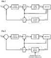
- a closed loop current controller for an electric actuatortypically takes the form shown in Figure 1 , where, using vector control, a voltage is applied to each phase winding of the motor and the resultant generated currents measured. The measured currents are then used by a controller, typically a PI, to control to the requested target current. A signal which gives the electrical position of the motor is also required so that the voltages can be applied at the correct phases at the correct times.
- a position sensoris shown but the present invention is equally applicable to a position sensorless system, where the position signal is estimated from other sensor measurements.
- the measurement processcan introduce harmonics into the output signal of the current sensor that are not present in the currents that are being measured.
- the current controllerthen reacts to these harmonics in the sensor output to try to remove them, but their removal by the current controller, to give a smooth output from the current sensor, causes the actual currents to contain these harmonics.
- phase current measurementTypically two methods of phase current measurement are employed:
- the harmonics introducedwill be different, depending on the phase current measurement method used.
- the present inventionis applicable to any harmonic introduced by measurement inaccuracies.
- the distortion on the current measurementappears as an unknown disturbance on the current feedback path as shown in Figure 2 .
- the disturbancewill add harmonics to the 'measured current' signal from the sensor. If these disturbance harmonics fall within the bandwidth of the current controller, the current controller will act to reject them by modulating the control (voltage demand) signal in order to cancel them out. This modulation will cause the harmonics to appear on the actual phase currents, even though the harmonics are no longer present in the measured phase current signals. This will lead to unwanted torque ripple at the motor output shaft.
- the present inventionprovides a control system for an electric motor, the system comprising a current sensing means arranged to produce a current sensing output indicative of electric current in the motor, current control means arranged to receive the current sensing output and to output a voltage demand indicative of voltages to be applied to the motor, and current sensing correction means arranged to monitor the voltage demand to identify a component of the demanded voltage having a frequency equal to that of the distortion, to measure the magnitude of that component to measure the harmonic distortion and to generate a correction signal from the measured harmonic distortion that is dependent on the measured magnitude, and in which the system is further arranged to combine the correction signal with the current sensing output to produce a corrected current sensing output in which the harmonic distortion is reduced.
- the distortionmay be of one or more specific frequencies which may be one or more harmonics of the motor speed and therefore variable with the motor speed, or may be fixed frequencies which are independent of motor speed.
- the motormay have stationary windings and a rotor which rotates relative to the windings.
- the current sensing meansmay comprise a current sensor arranged to measure current in the motor windings. The current may be measured as two components in the frame of reference of the windings.
- the current sensing meansmay comprise transformation means arranged to transform the measured current into the frame of reference of the rotor, for example as torque-generating and non-torque-generating components.
- the current control meansmay be arranged to output the voltage demand so as to define a demanded voltage in a frame of reference which is stationary, which may be the frame of reference of the windings and defined, for example, as ⁇ and ⁇ components, or in a rotating frame of reference, which may be the frame of reference of the rotor, and defined, for example, as D and Q axis components.
- the correction meansmay be arranged to transform the demanded voltage, for example using a frequency transformation, so that the identified component becomes a DC component, and to measure the magnitude of the DC component.
- the current sensing meansmay include a current sensor and the correction means may be arranged to input the correction signal to the current sensor to adjust a parameter of the current sensor.
- the control systemmay be arranged to correct a plurality of components of distortion.
- the components of distortionmay be harmonics having different frequencies and/or different signs.
- a motor 10is controlled by a closed loop motor current control system according to an embodiment of the invention comprises a current sensing system 12 and a current controller 20.
- a current sensing system 12comprises a current sensor 14 arranged to measure the currents i U , i V , i w in the three phases of the motor, which comprise stationary windings, and output a signal indicative of the current vector in the stationary coordinates having ⁇ and ⁇ components.
- the current sensing systemfurther comprises a coordinate transformation block 16 arranged to convert the current vector from the ⁇ and ⁇ components in the stationary reference from, to D and Q components i D and i Q defining the current vector in the rotor reference frame, which rotates relative to the fixed windings, with the Q axis current being the torque generating component and the D axis current being non-torque-generating.
- a comparator 18receives the D and Q currents from the current sensing system 12 and compares them with demanded D and Q current components to generate an error.
- a current controller 20receives the current error and outputs a demanded voltage vector, in the form of a D and Q axis voltage demand V DQ calculated to reduce the current error so that the measured current vector approaches the demanded current vector.
- a further transformation block 22receives the voltage demand from the current controller and converts it to ⁇ and ⁇ components V ⁇ which are input to a PWM driver 24 which is arranged to control a number of switches to apply voltages to the phase windings of the motor in a PWM pattern which produces the net voltage in the windings having a magnitude and direction corresponding to the voltage demand vector.
- the current sensor 14 in this systemproduces harmonic interferences as described above.
- the current measurement erroris not observable in the current error signal input to the controller 20. However, if the disturbance harmonic falls within the bandwidth of the current controller 20 it will be observable on the controller (voltage demand) signal output from the current controller 20.
- the control systemis therefore arranged provide a harmonic compensation function. To achieve this it is arranged to monitor the voltage demand, in this case by monitoring V DQ , to measure the harmonic interference, and apply a correction to the current measurement signal output from the current sensor 14 such that the measurement error is removed.
- the compensation process that the control system is arranged to performcan be broken down into three steps:
- the approach used in this embodimentis to use a synchronous filter that is arranged to transform the control voltage demand to the isolation frequency reference frame. This allows the unwanted harmonic, which is in this case assumed to be a single harmonic of known frequency, to be isolated simply.
- Figure 4shows one implementation of a synchronous filter 40, which receives as inputs the current controller output voltage demand V DQ , the motor electrical position ⁇ and the harmonic k (relative to the motor electrical frequency) to be isolated.
- kcan be positive or negative depending on whether the targeted harmonic is a positive or negative sequence component (i.e. whether it travels in the same direction as the rotor or the opposite direction).
- the transformed signal output by the synchronous filter 40will contain DC and AC components.
- the DC componentis the quadrature component of the target harmonic.
- the AC componentsare caused by all of the other harmonics in the original signal. If the DC component is zero then the isolation frequency is not present in the current controller output voltages.
- a filter 50may be added to the control path at the output of the synchronous filter 40 to help to attenuate the unwanted AC components so that the DC component can be more easily isolated.
- the synchronous filter 40produces a signal where the DC component is the magnitude of the unwanted harmonic. If the DC component is zero then the harmonic is not present.
- the aim of the control step of the processis therefore to generate a correction signal(s) which can be fed back into the current sensing system to reduce the DC component of the synchronous filter output to zero.
- a number of controllersmay be used to perform this step, but the preferred solution is a controller of the standard PID form.
- Solution 1is suitable for most or all situations and has the advantage that it is inherently linear.
- Solution 2is most suitable when there is a monotonic (and preferably linear) relationship between the isolated harmonic signal and the parameter being modified (e.g. the gain or offset of the signal). However there are many situations where this is not the case, in which case solution 1 may be preferred.
- the preferred solutionis to cancel out the harmonics by adding the correction signal to the current measurement signal in anti-phase with the unwanted harmonic.
- Figure 6shows a scheme to achieve this. This comprises a synchronous filter 60 with a filter 61 filtering its output similar to that of Figure 5 .
- a controller 62receives the output from the synchronous filter 60, after filtering by a filter 61, and calculates the DC correction i con required to reduce the DC component of the synchronous filter output to zero.
- a transformation block 63performs a transformation which is the inverse of that performed by the synchronous filter to convert this DC correction to a sinusoidal correction signal i corr equal to the unwanted harmonic.
- An adder 66adds the sinusoidal correction signals to the DQ axis current measurement output by the current sensing system, which comprises a current sensor 64 and coordinate transformation block 65 similar to that of Figure 3 .
- This correction signaltherefore has the correct amplitude and phase to cancel out the measurement error.
- a synchronous filter 70 with output filter 71correspond to those of Figure 6 .
- the controller 72 which receives the filtered output from the synchronous filter 70is arranged to calculate, from the measured magnitude of the target harmonic, a control output i con which is input directly to the current sensor 74 to control a parameter (such as gain or offset) of the current sensor 74 so that the current sensor's output, which is transformed to the DQ axis currents by a coordinate transformation block 75, will have the unwanted harmonic removed.
- a control output i conwhich is input directly to the current sensor 74 to control a parameter (such as gain or offset) of the current sensor 74 so that the current sensor's output, which is transformed to the DQ axis currents by a coordinate transformation block 75, will have the unwanted harmonic removed.
- a limitation of the techniques described aboveis that at low motor speeds the DC component cannot be easily isolated (and at zero speed is impossible to isolate). As a result a limit should be placed on the minimum electrical frequency at which the algorithm may operate. Similarly, it may be necessary to have an upper operating speed for the algorithm to avoid aliasing problems if the sample rate of the algorithm is not sufficiently high.
- the use of hysteresis on the operating speed limitsmay be used and / or the control action may be ramped on and off linearly over a period of time (or number of electrical cycles).
- control systemmay be arranged to do any one or more of the following:
- a motor control systemcomprises identical components to that of Figure 3 , with corresponding components indicated by the same reference numerals increased by 100.
- the complete harmonic compensation algorithmcomprises three sub-algorithms 130, 132, 134 all operating in parallel. Each of these sub-algorithms can correspond either to that of Figure 6 or Figure 7 and each is arranged to isolate and correct a different harmonic frequency.
- the number and order and sign of the harmonics that the compensation sub-algorithms are arranged to correctwill depend on the nature of the current sensing system and the harmonic distortions that it produces. For example in some cases there may be two sub-algorithms arranged to correct two harmonics. These can be of the same order and different signs, of different order and the same sign, or of different order and different sign. In some cases there may be three sub-algorithms as shown in Figure 8 . In this case the three harmonics can be made up of two of the same order and opposite sign and one of a different order (and either sign), or three different orders, and all positive, all negative, two negative and one positive, or two positive and one negative.
- the voltage demandis monitored in the D,Q axis reference frame, and the harmonic compensation version of the correction is carried out on the D and Q axis current measurement signal
- the voltage demand monitoringis carried out in the static ⁇ and ⁇ reference frame, i.e. at the output of the transformation block 22, and the harmonic compensation to be applied to the current sensor output in the ⁇ and ⁇ reference frame, i.e. as it is output by the sensor 14 and before it is input to the transformation block 16.
Landscapes
- Engineering & Computer Science (AREA)
- Power Engineering (AREA)
- Control Of Ac Motors In General (AREA)
- Control Of Motors That Do Not Use Commutators (AREA)
Description
- The present invention relates to the control of electric motors, and in particular to measurement of current in electric motors and the control of electric motors based on current measurement.
- A closed loop current controller for an electric actuator typically takes the form shown in
Figure 1 , where, using vector control, a voltage is applied to each phase winding of the motor and the resultant generated currents measured. The measured currents are then used by a controller, typically a PI, to control to the requested target current. A signal which gives the electrical position of the motor is also required so that the voltages can be applied at the correct phases at the correct times. In the system ofFigure 1 a position sensor is shown but the present invention is equally applicable to a position sensorless system, where the position signal is estimated from other sensor measurements. - Due to inaccuracies and limitations of the current sensor the measurement process can introduce harmonics into the output signal of the current sensor that are not present in the currents that are being measured. The current controller then reacts to these harmonics in the sensor output to try to remove them, but their removal by the current controller, to give a smooth output from the current sensor, causes the actual currents to contain these harmonics.
- Depending on the frequency and amplitude of these unwanted harmonics the torque produced by the motor can be degraded, with the harmonics potentially causing torque ripple and / or acoustic noise.
- Typically two methods of phase current measurement are employed:
- 1. Phase current sensors, where a current measurement device is placed in each of the phases. (For a three phase system it may be that only 2 phases are measured as the 3rd phase can be calculated from the 2 measured phases)
- 2. Single current sensor, where the current flowing in the DC link is measured at specific points during the PWM duty cycle to allow the current in the 3 phases to be calculated.
- The harmonics introduced will be different, depending on the phase current measurement method used. The present invention is applicable to any harmonic introduced by measurement inaccuracies.
- The effect of a distortion on the feedback measurement signal in any closed loop system is well known from standard control theory. The effect is described explicitly below for the case of a motor current controller.
- The distortion on the current measurement appears as an unknown disturbance on the current feedback path as shown in
Figure 2 . The disturbance will add harmonics to the 'measured current' signal from the sensor. If these disturbance harmonics fall within the bandwidth of the current controller, the current controller will act to reject them by modulating the control (voltage demand) signal in order to cancel them out. This modulation will cause the harmonics to appear on the actual phase currents, even though the harmonics are no longer present in the measured phase current signals. This will lead to unwanted torque ripple at the motor output shaft. - TheIEEE publication "Correction on Current Measurement Errors for Accurate Flux Estimation of AC Drives at Low Stator Frequency" (XP011206331) discloses a motor control system (
Fig.4 ) in which voltage command signals (ve* fb) are observed (Fig.2 ) to be subtracted from the output (ids_AD) of a current sensing unit ("Measurement Error") and thereby generate a corrected current sensing signal (ies). - The present invention provides a control system for an electric motor, the system comprising a current sensing means arranged to produce a current sensing output indicative of electric current in the motor, current control means arranged to receive the current sensing output and to output a voltage demand indicative of voltages to be applied to the motor, and current sensing correction means arranged to monitor the voltage demand to identify a component of the demanded voltage having a frequency equal to that of the distortion, to measure the magnitude of that component to measure the harmonic distortion and to generate a correction signal from the measured harmonic distortion that is dependent on the measured magnitude, and in which the system is further arranged to combine the correction signal with the current sensing output to produce a corrected current sensing output in which the harmonic distortion is reduced.
- The distortion may be of one or more specific frequencies which may be one or more harmonics of the motor speed and therefore variable with the motor speed, or may be fixed frequencies which are independent of motor speed.
- The motor may have stationary windings and a rotor which rotates relative to the windings. The current sensing means may comprise a current sensor arranged to measure current in the motor windings. The current may be measured as two components in the frame of reference of the windings. The current sensing means may comprise transformation means arranged to transform the measured current into the frame of reference of the rotor, for example as torque-generating and non-torque-generating components.
- The current control means may be arranged to output the voltage demand so as to define a demanded voltage in a frame of reference which is stationary, which may be the frame of reference of the windings and defined, for example, as α and β components, or in a rotating frame of reference, which may be the frame of reference of the rotor, and defined, for example, as D and Q axis components.
- The correction means may be arranged to transform the demanded voltage, for example using a frequency transformation, so that the identified component becomes a DC component, and to measure the magnitude of the DC component.
- Alternatively, the current sensing means may include a current sensor and the correction means may be arranged to input the correction signal to the current sensor to adjust a parameter of the current sensor.
- The control system may be arranged to correct a plurality of components of distortion. For example the components of distortion may be harmonics having different frequencies and/or different signs.
- Preferred embodiments of the present invention will now be described by way of example only with reference to the accompanying drawings.
Figure 1 is a diagram of a known closed loop current control system for a motor;Figure 2 is a diagram showing how current measurement error affects the system ofFigure 1 ;Figure 3 is a diagram of a closed loop current control system for a motor according to an embodiment of the invention;Figure 4 is a diagram of a synchronous filter forming part of the system ofFigure 3 ;Figure 5 is a diagram of a filter arrangement similar to that ofFigure 4 but with a further filter component;Figure 6 is a diagram of part of the system ofFigure 3 arranged to correct D and Q axis current measurements;Figure 7 is a diagram of part of a system of a further embodiment arranged to correct operation of the current sensor directly.Figure 8 is a diagram of a control system according to a further embodiment of the invention.- Referring to
Figure 3 amotor 10 is controlled by a closed loop motor current control system according to an embodiment of the invention comprises acurrent sensing system 12 and acurrent controller 20. Acurrent sensing system 12 comprises acurrent sensor 14 arranged to measure the currents iU, iV, iw in the three phases of the motor, which comprise stationary windings, and output a signal indicative of the current vector in the stationary coordinates having α and β components. The current sensing system further comprises acoordinate transformation block 16 arranged to convert the current vector from the α and β components in the stationary reference from, to D and Q components iD and iQ defining the current vector in the rotor reference frame, which rotates relative to the fixed windings, with the Q axis current being the torque generating component and the D axis current being non-torque-generating. Acomparator 18 receives the D and Q currents from thecurrent sensing system 12 and compares them with demanded D and Q current components to generate an error. Acurrent controller 20 receives the current error and outputs a demanded voltage vector, in the form of a D and Q axis voltage demand VDQ calculated to reduce the current error so that the measured current vector approaches the demanded current vector. A further transformation block 22 receives the voltage demand from the current controller and converts it to α and β components Vαβ which are input to aPWM driver 24 which is arranged to control a number of switches to apply voltages to the phase windings of the motor in a PWM pattern which produces the net voltage in the windings having a magnitude and direction corresponding to the voltage demand vector. - The
current sensor 14 in this system produces harmonic interferences as described above. The current measurement error is not observable in the current error signal input to thecontroller 20. However, if the disturbance harmonic falls within the bandwidth of thecurrent controller 20 it will be observable on the controller (voltage demand) signal output from thecurrent controller 20. - The control system is therefore arranged provide a harmonic compensation function. To achieve this it is arranged to monitor the voltage demand, in this case by monitoring VDQ, to measure the harmonic interference, and apply a correction to the current measurement signal output from the
current sensor 14 such that the measurement error is removed. The compensation process that the control system is arranged to perform can be broken down into three steps: - 1. Isolation - Monitoring the voltages demanded by the
current controller 20 and isolating the unwanted frequencies. - 2. Control - Generating a control (cancellation) signal arranged to reduce the unwanted harmonics to zero.
- 3. Correction - Applying the control (cancellation) signal to the current measurement system in a closed loop.
- Although a number of techniques may be used to isolate the unwanted harmonics, such as a runtime Fast Fourier Transform or notch filter, the approach used in this embodiment is to use a synchronous filter that is arranged to transform the control voltage demand to the isolation frequency reference frame. This allows the unwanted harmonic, which is in this case assumed to be a single harmonic of known frequency, to be isolated simply.
Figure 4 shows one implementation of asynchronous filter 40, which receives as inputs the current controller output voltage demand VDQ, the motor electrical position θ and the harmonic k (relative to the motor electrical frequency) to be isolated. Note that k can be positive or negative depending on whether the targeted harmonic is a positive or negative sequence component (i.e. whether it travels in the same direction as the rotor or the opposite direction).- The transformation ejk
θ performed by thefilter 40 is defined as:
filter 40, y(t) is the output, and θ is the electrical position of the motor. - The transformed signal output by the
synchronous filter 40 will contain DC and AC components. The DC component is the quadrature component of the target harmonic. The AC components are caused by all of the other harmonics in the original signal. If the DC component is zero then the isolation frequency is not present in the current controller output voltages. As shown inFigure 5 , if necessary afilter 50 may be added to the control path at the output of thesynchronous filter 40 to help to attenuate the unwanted AC components so that the DC component can be more easily isolated. - Although this technique has been described in relation to the removal of harmonics associated with the motor electrical frequency it may be also be used to remove fixed frequency distortion. In this situation the angular input is generated at a fixed frequency and not derived from the motor electrical position.
- As previously described with reference to
Figures 4 and 5 , thesynchronous filter 40 produces a signal where the DC component is the magnitude of the unwanted harmonic. If the DC component is zero then the harmonic is not present. - The aim of the control step of the process is therefore to generate a correction signal(s) which can be fed back into the current sensing system to reduce the DC component of the synchronous filter output to zero. A number of controllers may be used to perform this step, but the preferred solution is a controller of the standard PID form.
- Referring back to
Figure 3 , once the required control action has been calculated the corrective action must be applied to the current sensing system. This can be achieved in a number of ways including: - 1. Apply a sinusoidal correction to the current measurement, i.e. to the current sensor output, in anti-phase with the unwanted harmonic to cancel out the harmonic.
- 2. Modify the current measurements directly (for example to compensate for a gain or offset measurement error)
- Solution 1 is suitable for most or all situations and has the advantage that it is inherently linear. Solution 2 is most suitable when there is a monotonic (and preferably linear) relationship between the isolated harmonic signal and the parameter being modified (e.g. the gain or offset of the signal). However there are many situations where this is not the case, in which case solution 1 may be preferred.
- In many cases, the preferred solution is to cancel out the harmonics by adding the correction signal to the current measurement signal in anti-phase with the unwanted harmonic.
Figure 6 shows a scheme to achieve this. This comprises asynchronous filter 60 with afilter 61 filtering its output similar to that ofFigure 5 . Acontroller 62 receives the output from thesynchronous filter 60, after filtering by afilter 61, and calculates the DC correction icon required to reduce the DC component of the synchronous filter output to zero. Atransformation block 63 performs a transformation which is the inverse of that performed by the synchronous filter to convert this DC correction to a sinusoidal correction signal icorr equal to the unwanted harmonic. Anadder 66 adds the sinusoidal correction signals to the DQ axis current measurement output by the current sensing system, which comprises acurrent sensor 64 and coordinatetransformation block 65 similar to that ofFigure 3 . This correction signal therefore has the correct amplitude and phase to cancel out the measurement error. - Referring to
Figure 7 in a system according to a further embodiment of the invention asynchronous filter 70 withoutput filter 71 correspond to those ofFigure 6 . However thecontroller 72 which receives the filtered output from thesynchronous filter 70 is arranged to calculate, from the measured magnitude of the target harmonic, a control output icon which is input directly to thecurrent sensor 74 to control a parameter (such as gain or offset) of thecurrent sensor 74 so that the current sensor's output, which is transformed to the DQ axis currents by a coordinatetransformation block 75, will have the unwanted harmonic removed. - A limitation of the techniques described above is that at low motor speeds the DC component cannot be easily isolated (and at zero speed is impossible to isolate). As a result a limit should be placed on the minimum electrical frequency at which the algorithm may operate. Similarly, it may be necessary to have an upper operating speed for the algorithm to avoid aliasing problems if the sample rate of the algorithm is not sufficiently high.
- To minimise torque disturbances during the enabling and disabling of the algorithm the use of hysteresis on the operating speed limits may be used and / or the control action may be ramped on and off linearly over a period of time (or number of electrical cycles).
- When the algorithm is disabled a number of options are available, and the control system may be arranged to do any one or more of the following:
- 1. Fix the control action at the last calculated value (for the harmonic compensation algorithm the variation of position will still continue to generate the corrective action at the required harmonic frequency).
- 2. Switch to an alternative harmonic compensation algorithm.
- 3. Disable the harmonic compensation completely.
- It is common for current measurement errors to lead to distortions at several harmonic frequencies. This algorithm can cancel several frequencies simultaneously by combining multiple harmonic compensation algorithms in parallel. This is because the harmonic compensation controllers operate completely independently at different frequencies. Referring to
Figure 8 , a motor control system according to a further embodiment of the invention comprises identical components to that ofFigure 3 , with corresponding components indicated by the same reference numerals increased by 100. In this embodiment the complete harmonic compensation algorithm comprises threesub-algorithms Figure 6 orFigure 7 and each is arranged to isolate and correct a different harmonic frequency. It will be appreciated that the number and order and sign of the harmonics that the compensation sub-algorithms are arranged to correct will depend on the nature of the current sensing system and the harmonic distortions that it produces. For example in some cases there may be two sub-algorithms arranged to correct two harmonics. These can be of the same order and different signs, of different order and the same sign, or of different order and different sign. In some cases there may be three sub-algorithms as shown inFigure 8 . In this case the three harmonics can be made up of two of the same order and opposite sign and one of a different order (and either sign), or three different orders, and all positive, all negative, two negative and one positive, or two positive and one negative. - While in the embodiments described above the voltage demand is monitored in the D,Q axis reference frame, and the harmonic compensation version of the correction is carried out on the D and Q axis current measurement signal, it is equally possible for the voltage demand monitoring to be carried out in the static α and β reference frame, i.e. at the output of the transformation block 22, and the harmonic compensation to be applied to the current sensor output in the α and β reference frame, i.e. as it is output by the
sensor 14 and before it is input to thetransformation block 16.

Claims (7)
- A control system for an electric motor (10), the system comprising a current sensing means (12, 14; 64) arranged to produce a current sensing output (i) indicative of electric current in the motor (10), current control means (20) arranged to receive the current sensing output (iαβ) and to output a voltage demand (VDQ) indicative of voltages to be applied to the motor (10), and current sensing correction means (18) arranged to monitor the voltage demand (VDQ) to identify a
component of the demanded voltage having a frequency equal to that of a harmonic distortion, to measure the magnitude of that component to measure the harmonic distortion and to generate a correction signal (icorr) from the measured
harmonic distortion that is dependent on the measured magnitude, and in which the system is further arranged to combine (66) the correction signal (icorr) with the
current sensing output (i) to produce a corrected current sensing output (iDQ) in which the harmonic distortion is reduced. - A control system according to claim 1 for a motor (10) having stationary windings and a rotor which rotates relative to the windings, wherein the current sensing means (12) comprises a current sensor (14) arranged to measure current in the motor windings and transformation means (22) arranged to transform the measured current into the frame of reference of the rotor.
- A control system according to claim 1 or claim 2 wherein the current control means (20) is arranged to output the voltage demand so as to define a demanded voltage in a frame of reference which rotates.
- A control system according to any preceding claim wherein the correction means (18) is arranged to transform the demanded voltage so that the identified component becomes a DC component, and to measure the magnitude of the DC component.
- A control system according to any of claims 1 to 3 wherein the current sensing means (12) includes a current sensor (14) and the correction means is arranged to input the correction signal to the current sensor (14) to adjust a parameter of the current sensor (14).
- A control system according to any preceding claim which is arranged to correct a plurality of components of distortion.
- A control system according to claim 6 wherein the components of distortion are harmonics having different frequencies and/or different signs.
Applications Claiming Priority (2)
| Application Number | Priority Date | Filing Date | Title |
|---|---|---|---|
| GBGB1003456.9AGB201003456D0 (en) | 2010-03-02 | 2010-03-02 | Current sensor error compensation |
| PCT/GB2011/050303WO2011107773A2 (en) | 2010-03-02 | 2011-02-16 | Current sensor error compensation |
Publications (2)
| Publication Number | Publication Date |
|---|---|
| EP2543133A2 EP2543133A2 (en) | 2013-01-09 |
| EP2543133B1true EP2543133B1 (en) | 2017-04-05 |
Family
ID=42125845
Family Applications (1)
| Application Number | Title | Priority Date | Filing Date |
|---|---|---|---|
| EP11715014.4AActiveEP2543133B1 (en) | 2010-03-02 | 2011-02-16 | Current sensor error compensation |
Country Status (5)
| Country | Link |
|---|---|
| US (1) | US9966882B2 (en) |
| EP (1) | EP2543133B1 (en) |
| CN (1) | CN102986132B (en) |
| GB (1) | GB201003456D0 (en) |
| WO (1) | WO2011107773A2 (en) |
Families Citing this family (48)
| Publication number | Priority date | Publication date | Assignee | Title |
|---|---|---|---|---|
| US8744384B2 (en) | 2000-07-20 | 2014-06-03 | Blackberry Limited | Tunable microwave devices with auto-adjusting matching circuit |
| US9406444B2 (en) | 2005-11-14 | 2016-08-02 | Blackberry Limited | Thin film capacitors |
| US7711337B2 (en) | 2006-01-14 | 2010-05-04 | Paratek Microwave, Inc. | Adaptive impedance matching module (AIMM) control architectures |
| US7535312B2 (en) | 2006-11-08 | 2009-05-19 | Paratek Microwave, Inc. | Adaptive impedance matching apparatus, system and method with improved dynamic range |
| US7714676B2 (en) | 2006-11-08 | 2010-05-11 | Paratek Microwave, Inc. | Adaptive impedance matching apparatus, system and method |
| US7917104B2 (en) | 2007-04-23 | 2011-03-29 | Paratek Microwave, Inc. | Techniques for improved adaptive impedance matching |
| US8213886B2 (en) | 2007-05-07 | 2012-07-03 | Paratek Microwave, Inc. | Hybrid techniques for antenna retuning utilizing transmit and receive power information |
| US7991363B2 (en) | 2007-11-14 | 2011-08-02 | Paratek Microwave, Inc. | Tuning matching circuits for transmitter and receiver bands as a function of transmitter metrics |
| US8072285B2 (en) | 2008-09-24 | 2011-12-06 | Paratek Microwave, Inc. | Methods for tuning an adaptive impedance matching network with a look-up table |
| US8472888B2 (en) | 2009-08-25 | 2013-06-25 | Research In Motion Rf, Inc. | Method and apparatus for calibrating a communication device |
| US9026062B2 (en) | 2009-10-10 | 2015-05-05 | Blackberry Limited | Method and apparatus for managing operations of a communication device |
| GB201003456D0 (en)* | 2010-03-02 | 2010-04-14 | Trw Ltd | Current sensor error compensation |
| US8803631B2 (en) | 2010-03-22 | 2014-08-12 | Blackberry Limited | Method and apparatus for adapting a variable impedance network |
| GB201006404D0 (en) | 2010-04-16 | 2010-06-02 | Trw Ltd | Motor control with voltage harmonic shaping |
| JP5901612B2 (en) | 2010-04-20 | 2016-04-13 | ブラックベリー リミテッド | Method and apparatus for managing interference in a communication device |
| US9379454B2 (en) | 2010-11-08 | 2016-06-28 | Blackberry Limited | Method and apparatus for tuning antennas in a communication device |
| US8712340B2 (en) | 2011-02-18 | 2014-04-29 | Blackberry Limited | Method and apparatus for radio antenna frequency tuning |
| US8655286B2 (en) | 2011-02-25 | 2014-02-18 | Blackberry Limited | Method and apparatus for tuning a communication device |
| US8594584B2 (en) | 2011-05-16 | 2013-11-26 | Blackberry Limited | Method and apparatus for tuning a communication device |
| GB201109348D0 (en) | 2011-06-03 | 2011-07-20 | Trw Ltd | Motor control with voltage harmonic shaping |
| EP2740221B1 (en) | 2011-08-05 | 2019-06-26 | BlackBerry Limited | Method and apparatus for band tuning in a communication device |
| JP5808210B2 (en)* | 2011-09-27 | 2015-11-10 | 三菱重工業株式会社 | Motor control device and motor control method |
| DE102011088915B4 (en)* | 2011-12-16 | 2023-04-20 | Vitesco Technologies GmbH | Calculation of a reverse induced residual current ripple at a DC input of a motor controller for a synchronous machine |
| KR101883006B1 (en)* | 2012-02-17 | 2018-07-27 | 현대모비스 주식회사 | Motor control method of inverter |
| US8948889B2 (en) | 2012-06-01 | 2015-02-03 | Blackberry Limited | Methods and apparatus for tuning circuit components of a communication device |
| US9853363B2 (en) | 2012-07-06 | 2017-12-26 | Blackberry Limited | Methods and apparatus to control mutual coupling between antennas |
| US9246223B2 (en) | 2012-07-17 | 2016-01-26 | Blackberry Limited | Antenna tuning for multiband operation |
| US9350405B2 (en) | 2012-07-19 | 2016-05-24 | Blackberry Limited | Method and apparatus for antenna tuning and power consumption management in a communication device |
| US9413066B2 (en) | 2012-07-19 | 2016-08-09 | Blackberry Limited | Method and apparatus for beam forming and antenna tuning in a communication device |
| US9362891B2 (en) | 2012-07-26 | 2016-06-07 | Blackberry Limited | Methods and apparatus for tuning a communication device |
| US10404295B2 (en) | 2012-12-21 | 2019-09-03 | Blackberry Limited | Method and apparatus for adjusting the timing of radio antenna tuning |
| US9374113B2 (en) | 2012-12-21 | 2016-06-21 | Blackberry Limited | Method and apparatus for adjusting the timing of radio antenna tuning |
| WO2014116627A1 (en)* | 2013-01-22 | 2014-07-31 | Trane International Inc. | Variable frequency drive active harmonic mitigation controls and diagnostics |
| US9654049B2 (en) | 2013-01-22 | 2017-05-16 | Trane International, Inc. | Variable frequency drive active harmonic mitigation controls and diagnostics |
| JP5920300B2 (en)* | 2013-09-18 | 2016-05-18 | 株式会社デンソー | Power conversion device and electric power steering device using the same |
| US9802642B2 (en)* | 2014-04-11 | 2017-10-31 | Steering Solutions Ip Holding Corporation | Phase current measurement diagnostic |
| US9588155B2 (en)* | 2014-10-16 | 2017-03-07 | Freescale Semiconductor, Inc. | Current detection circuit with over-current protection |
| EP3024136A1 (en) | 2014-11-18 | 2016-05-25 | Siemens Aktiengesellschaft | Efficient damping of oscillations of an electrical machine |
| US9438319B2 (en) | 2014-12-16 | 2016-09-06 | Blackberry Limited | Method and apparatus for antenna selection |
| KR102000060B1 (en)* | 2015-04-09 | 2019-07-18 | 엘에스산전 주식회사 | Apparatus for correcting offset of current sensor |
| JP6527747B2 (en)* | 2015-05-12 | 2019-06-05 | 日立オートモティブシステムズ株式会社 | Inverter controller |
| DE102015116212A1 (en) | 2015-09-25 | 2017-03-30 | Robert Bosch Automotive Steering Gmbh | METHOD FOR OPERATING A PERMANENT REAR SYNCHRONIZED MACHINE, ESPECIALLY A SERVO MOTOR IN A STEERING SYSTEM |
| GB201604663D0 (en) | 2016-03-18 | 2016-05-04 | Trw Ltd | Control system for electric motor |
| FR3060127B1 (en)* | 2016-12-13 | 2019-03-15 | Seb S.A. | METHOD FOR DYNAMICALLY COMPENSATING THE OFFSET ERROR OF AN ACQUISITION CHAIN COMPRISING A CURRENT SENSOR |
| US11378597B2 (en)* | 2019-11-29 | 2022-07-05 | Steering Solutions Ip Holding Corporation | Closed-loop compensation of current measurement offset errors in alternating current motor drives |
| US11002804B1 (en) | 2020-01-14 | 2021-05-11 | Honeywell International Inc. | Magnetic field sensor compensation methods and systems |
| CN115032645B (en)* | 2022-06-09 | 2025-05-06 | 国网江苏省电力有限公司泰州供电分公司 | A high-precision distance measurement method for unmanned aerial vehicle inspection |
| DE102024202220A1 (en)* | 2024-03-08 | 2025-09-11 | Robert Bosch Gesellschaft mit beschränkter Haftung | Method for calibrating current sensors, control device for an electric drive system and electric drive system |
Family Cites Families (39)
| Publication number | Priority date | Publication date | Assignee | Title |
|---|---|---|---|---|
| JPS57199489A (en)* | 1981-05-29 | 1982-12-07 | Hitachi Ltd | Controller for induction motor |
| US4677364A (en)* | 1985-01-04 | 1987-06-30 | The United States Of America As Represented By The United States Department Of Energy | Reactive power compensating system |
| DE3679620D1 (en)* | 1985-09-09 | 1991-07-11 | Toshiba Kawasaki Kk | AC POWER SUPPLY. |
| US4658192A (en)* | 1986-01-31 | 1987-04-14 | General Electric Company | Programmable deadband current regulator |
| US5457375A (en)* | 1994-05-27 | 1995-10-10 | Emerson Electric Co. | Sensorless commutation controller for a poly-phase dynamoelectric machine |
| JP3201457B2 (en)* | 1995-08-21 | 2001-08-20 | 株式会社安川電機 | Induction motor flux estimator Input voltage error correction method and induction motor flux estimator |
| US5811949A (en)* | 1997-09-25 | 1998-09-22 | Allen Bradley Company, Llc | Turn-on delay compensator for motor control |
| US6424107B1 (en)* | 2000-09-06 | 2002-07-23 | Trw Inc. | Apparatus and method for controlling an electric motor |
| US6362593B1 (en)* | 2001-01-05 | 2002-03-26 | Samsung Electronics Co., Ltd. | Apparatus and method for compensating dead time of motor |
| JP3699663B2 (en)* | 2001-05-24 | 2005-09-28 | 勲 高橋 | Inverter control method and apparatus |
| JP3582505B2 (en)* | 2001-09-10 | 2004-10-27 | 日産自動車株式会社 | Motor control device |
| US6777907B2 (en)* | 2001-11-06 | 2004-08-17 | International Rectifier Corporation | Current ripple reduction by harmonic current regulation |
| TW200405646A (en)* | 2002-05-24 | 2004-04-01 | Virginia Tech Intell Prop | Method, apparatus, and system for drive control, power conversion, and start-up control in an SRM or PMBDCM drive system |
| US7117754B2 (en)* | 2002-10-28 | 2006-10-10 | The Curators Of The University Of Missouri | Torque ripple sensor and mitigation mechanism |
| US6998811B2 (en)* | 2003-02-10 | 2006-02-14 | Ford Global Technologies, Llc | Compensation method for current-sensor gain errors |
| JP3955287B2 (en)* | 2003-04-03 | 2007-08-08 | 松下電器産業株式会社 | Inverter control device for motor drive and air conditioner |
| US7650760B2 (en)* | 2003-04-22 | 2010-01-26 | Panasonic Corporation | Motor controlling device, compressor, air conditioner and refrigerator |
| WO2005035333A1 (en)* | 2003-10-07 | 2005-04-21 | Jtekt Corporation | Electric power steering device |
| US7166982B2 (en)* | 2003-10-15 | 2007-01-23 | International Rectifier Corporation | Hardware based configurable motion control apparatus and method |
| JP4422567B2 (en)* | 2004-06-30 | 2010-02-24 | 株式会社日立製作所 | Motor drive device, electric actuator, and electric power steering device |
| JP4561318B2 (en)* | 2004-11-05 | 2010-10-13 | 日本精工株式会社 | Electric power steering device |
| JP4589093B2 (en)* | 2004-12-10 | 2010-12-01 | 日立オートモティブシステムズ株式会社 | Synchronous motor driving apparatus and method |
| US7639518B2 (en)* | 2006-04-26 | 2009-12-29 | Nissan Motor Co., Ltd. | Device and method for controlling power converting device |
| JP2007306694A (en)* | 2006-05-10 | 2007-11-22 | Yaskawa Electric Corp | Inverter control device for induction motor |
| JP5072338B2 (en)* | 2006-12-12 | 2012-11-14 | ルネサスエレクトロニクス株式会社 | Control device for synchronous motor |
| US20090206902A1 (en)* | 2007-01-03 | 2009-08-20 | Yong Li | Method for providing power factor correction including synchronized current sensing and pwm generation |
| JP4988374B2 (en)* | 2007-02-15 | 2012-08-01 | 三洋電機株式会社 | Motor control device |
| US7449859B2 (en)* | 2007-02-20 | 2008-11-11 | Gm Global Technology Operations, Inc. | Reduction of subharmonic oscillation at high frequency operation of a power inverter |
| JP2009017715A (en)* | 2007-07-06 | 2009-01-22 | Nsk Ltd | Motor control device and electric power steering device using the same |
| US8410734B2 (en) | 2008-01-16 | 2013-04-02 | Jtekt Corporation | Motor control device and electric power steering device |
| JP4968089B2 (en)* | 2008-01-28 | 2012-07-04 | アイシン・エィ・ダブリュ株式会社 | Electric motor control device and drive device |
| EP2246238B1 (en)* | 2008-01-30 | 2014-08-13 | Mitsubishi Electric Corporation | Steering controller |
| JP5131467B2 (en)* | 2008-04-02 | 2013-01-30 | 富士電機株式会社 | Control device for power converter |
| US8751055B2 (en)* | 2009-12-10 | 2014-06-10 | Panasonic Corporation | Distributed power supply system |
| GB201003456D0 (en)* | 2010-03-02 | 2010-04-14 | Trw Ltd | Current sensor error compensation |
| US8378743B2 (en)* | 2010-03-04 | 2013-02-19 | Bose Corporation | Reducing pulse error distortion |
| GB201006404D0 (en)* | 2010-04-16 | 2010-06-02 | Trw Ltd | Motor control with voltage harmonic shaping |
| JP5193259B2 (en)* | 2010-09-14 | 2013-05-08 | 株式会社日立カーエンジニアリング | Motor control device and control method for electric oil pump |
| GB201109348D0 (en)* | 2011-06-03 | 2011-07-20 | Trw Ltd | Motor control with voltage harmonic shaping |
- 2010
- 2010-03-02GBGBGB1003456.9Apatent/GB201003456D0/ennot_activeCeased
- 2011
- 2011-02-16CNCN201180019255.7Apatent/CN102986132B/enactiveActive
- 2011-02-16WOPCT/GB2011/050303patent/WO2011107773A2/enactiveApplication Filing
- 2011-02-16EPEP11715014.4Apatent/EP2543133B1/enactiveActive
- 2011-02-16USUS13/581,933patent/US9966882B2/enactiveActive
Non-Patent Citations (1)
| Title |
|---|
| None* |
Also Published As
| Publication number | Publication date |
|---|---|
| GB201003456D0 (en) | 2010-04-14 |
| US9966882B2 (en) | 2018-05-08 |
| EP2543133A2 (en) | 2013-01-09 |
| CN102986132A (en) | 2013-03-20 |
| WO2011107773A3 (en) | 2011-12-29 |
| CN102986132B (en) | 2015-07-22 |
| US20130106332A1 (en) | 2013-05-02 |
| WO2011107773A2 (en) | 2011-09-09 |
Similar Documents
| Publication | Publication Date | Title |
|---|---|---|
| EP2543133B1 (en) | Current sensor error compensation | |
| US9041334B2 (en) | Motor control with voltage harmonic shaping | |
| EP2715931B1 (en) | Motor control with voltage harmonic shaping | |
| KR100790914B1 (en) | Method and apparatus for actively reducing torque irregularities in rotating electromagnetic devices | |
| CN113866480B (en) | Detection of offset errors in phase current measurements for motor control systems | |
| JP5637042B2 (en) | Electric motor pulsation suppressing device and electric motor pulsation suppressing method | |
| KR20120120391A (en) | Torque ripple suppression control apparatus and torque ripple suppression control method for rotating electrical machine | |
| US20160290320A1 (en) | Noise control for a wind turbine | |
| JP5621274B2 (en) | Motor torque control device | |
| WO2014088054A1 (en) | Periodic disturbance automatic suppression device | |
| WO2016117029A1 (en) | Angle error correction device for position detector and angle error correction method | |
| Harke et al. | Current measurement gain tuning using high-frequency signal injection | |
| JP2011176951A (en) | Torque controller for motor | |
| JP2010035352A (en) | Device for estimating rotor position of synchronous electric motor | |
| JP6183554B2 (en) | Periodic disturbance automatic suppression device | |
| EP1729405B1 (en) | Speed control apparatus of vector controlled alternating current motor | |
| EP3430716B1 (en) | Control system for electric motor | |
| Uphues et al. | Comparison of parameter identification approaches with linearised process models based on RLS for induction machines with P> 100 kW | |
| JP5106295B2 (en) | Rotor position estimation device for synchronous motor | |
| JP7291578B2 (en) | Rotating electric machine control method and rotating electric machine control system | |
| Lee et al. | Current sensor scale error compensation method for current vector-controlled PMSM drive at standstill | |
| CN106849819B (en) | Electrical system comprising an electrical apparatus, a three-phase inverter and a control device, and associated method | |
| JP2023072562A (en) | Motor control method and motor control device |
Legal Events
| Date | Code | Title | Description |
|---|---|---|---|
| PUAI | Public reference made under article 153(3) epc to a published international application that has entered the european phase | Free format text:ORIGINAL CODE: 0009012 | |
| 17P | Request for examination filed | Effective date:20120829 | |
| AK | Designated contracting states | Kind code of ref document:A2 Designated state(s):AL AT BE BG CH CY CZ DE DK EE ES FI FR GB GR HR HU IE IS IT LI LT LU LV MC MK MT NL NO PL PT RO RS SE SI SK SM TR | |
| DAX | Request for extension of the european patent (deleted) | ||
| 17Q | First examination report despatched | Effective date:20150429 | |
| GRAP | Despatch of communication of intention to grant a patent | Free format text:ORIGINAL CODE: EPIDOSNIGR1 | |
| INTG | Intention to grant announced | Effective date:20161118 | |
| GRAS | Grant fee paid | Free format text:ORIGINAL CODE: EPIDOSNIGR3 | |
| GRAA | (expected) grant | Free format text:ORIGINAL CODE: 0009210 | |
| AK | Designated contracting states | Kind code of ref document:B1 Designated state(s):AL AT BE BG CH CY CZ DE DK EE ES FI FR GB GR HR HU IE IS IT LI LT LU LV MC MK MT NL NO PL PT RO RS SE SI SK SM TR | |
| REG | Reference to a national code | Ref country code:GB Ref legal event code:FG4D | |
| REG | Reference to a national code | Ref country code:CH Ref legal event code:EP | |
| REG | Reference to a national code | Ref country code:AT Ref legal event code:REF Ref document number:882673 Country of ref document:AT Kind code of ref document:T Effective date:20170415 | |
| REG | Reference to a national code | Ref country code:IE Ref legal event code:FG4D | |
| REG | Reference to a national code | Ref country code:DE Ref legal event code:R096 Ref document number:602011036647 Country of ref document:DE | |
| REG | Reference to a national code | Ref country code:NL Ref legal event code:MP Effective date:20170405 | |
| REG | Reference to a national code | Ref country code:LT Ref legal event code:MG4D | |
| REG | Reference to a national code | Ref country code:AT Ref legal event code:MK05 Ref document number:882673 Country of ref document:AT Kind code of ref document:T Effective date:20170405 | |
| PG25 | Lapsed in a contracting state [announced via postgrant information from national office to epo] | Ref country code:NL Free format text:LAPSE BECAUSE OF FAILURE TO SUBMIT A TRANSLATION OF THE DESCRIPTION OR TO PAY THE FEE WITHIN THE PRESCRIBED TIME-LIMIT Effective date:20170405 | |
| PG25 | Lapsed in a contracting state [announced via postgrant information from national office to epo] | Ref country code:GR Free format text:LAPSE BECAUSE OF FAILURE TO SUBMIT A TRANSLATION OF THE DESCRIPTION OR TO PAY THE FEE WITHIN THE PRESCRIBED TIME-LIMIT Effective date:20170706 Ref country code:AT Free format text:LAPSE BECAUSE OF FAILURE TO SUBMIT A TRANSLATION OF THE DESCRIPTION OR TO PAY THE FEE WITHIN THE PRESCRIBED TIME-LIMIT Effective date:20170405 Ref country code:LT Free format text:LAPSE BECAUSE OF FAILURE TO SUBMIT A TRANSLATION OF THE DESCRIPTION OR TO PAY THE FEE WITHIN THE PRESCRIBED TIME-LIMIT Effective date:20170405 Ref country code:NO Free format text:LAPSE BECAUSE OF FAILURE TO SUBMIT A TRANSLATION OF THE DESCRIPTION OR TO PAY THE FEE WITHIN THE PRESCRIBED TIME-LIMIT Effective date:20170705 Ref country code:ES Free format text:LAPSE BECAUSE OF FAILURE TO SUBMIT A TRANSLATION OF THE DESCRIPTION OR TO PAY THE FEE WITHIN THE PRESCRIBED TIME-LIMIT Effective date:20170405 Ref country code:HR Free format text:LAPSE BECAUSE OF FAILURE TO SUBMIT A TRANSLATION OF THE DESCRIPTION OR TO PAY THE FEE WITHIN THE PRESCRIBED TIME-LIMIT Effective date:20170405 Ref country code:FI Free format text:LAPSE BECAUSE OF FAILURE TO SUBMIT A TRANSLATION OF THE DESCRIPTION OR TO PAY THE FEE WITHIN THE PRESCRIBED TIME-LIMIT Effective date:20170405 | |
| PG25 | Lapsed in a contracting state [announced via postgrant information from national office to epo] | Ref country code:RS Free format text:LAPSE BECAUSE OF FAILURE TO SUBMIT A TRANSLATION OF THE DESCRIPTION OR TO PAY THE FEE WITHIN THE PRESCRIBED TIME-LIMIT Effective date:20170405 Ref country code:SE Free format text:LAPSE BECAUSE OF FAILURE TO SUBMIT A TRANSLATION OF THE DESCRIPTION OR TO PAY THE FEE WITHIN THE PRESCRIBED TIME-LIMIT Effective date:20170405 Ref country code:LV Free format text:LAPSE BECAUSE OF FAILURE TO SUBMIT A TRANSLATION OF THE DESCRIPTION OR TO PAY THE FEE WITHIN THE PRESCRIBED TIME-LIMIT Effective date:20170405 Ref country code:IS Free format text:LAPSE BECAUSE OF FAILURE TO SUBMIT A TRANSLATION OF THE DESCRIPTION OR TO PAY THE FEE WITHIN THE PRESCRIBED TIME-LIMIT Effective date:20170805 Ref country code:PL Free format text:LAPSE BECAUSE OF FAILURE TO SUBMIT A TRANSLATION OF THE DESCRIPTION OR TO PAY THE FEE WITHIN THE PRESCRIBED TIME-LIMIT Effective date:20170405 Ref country code:BG Free format text:LAPSE BECAUSE OF FAILURE TO SUBMIT A TRANSLATION OF THE DESCRIPTION OR TO PAY THE FEE WITHIN THE PRESCRIBED TIME-LIMIT Effective date:20170705 | |
| REG | Reference to a national code | Ref country code:DE Ref legal event code:R097 Ref document number:602011036647 Country of ref document:DE | |
| PG25 | Lapsed in a contracting state [announced via postgrant information from national office to epo] | Ref country code:SK Free format text:LAPSE BECAUSE OF FAILURE TO SUBMIT A TRANSLATION OF THE DESCRIPTION OR TO PAY THE FEE WITHIN THE PRESCRIBED TIME-LIMIT Effective date:20170405 Ref country code:CZ Free format text:LAPSE BECAUSE OF FAILURE TO SUBMIT A TRANSLATION OF THE DESCRIPTION OR TO PAY THE FEE WITHIN THE PRESCRIBED TIME-LIMIT Effective date:20170405 Ref country code:EE Free format text:LAPSE BECAUSE OF FAILURE TO SUBMIT A TRANSLATION OF THE DESCRIPTION OR TO PAY THE FEE WITHIN THE PRESCRIBED TIME-LIMIT Effective date:20170405 Ref country code:DK Free format text:LAPSE BECAUSE OF FAILURE TO SUBMIT A TRANSLATION OF THE DESCRIPTION OR TO PAY THE FEE WITHIN THE PRESCRIBED TIME-LIMIT Effective date:20170405 Ref country code:RO Free format text:LAPSE BECAUSE OF FAILURE TO SUBMIT A TRANSLATION OF THE DESCRIPTION OR TO PAY THE FEE WITHIN THE PRESCRIBED TIME-LIMIT Effective date:20170405 | |
| PLBE | No opposition filed within time limit | Free format text:ORIGINAL CODE: 0009261 | |
| STAA | Information on the status of an ep patent application or granted ep patent | Free format text:STATUS: NO OPPOSITION FILED WITHIN TIME LIMIT | |
| REG | Reference to a national code | Ref country code:FR Ref legal event code:PLFP Year of fee payment:8 | |
| PG25 | Lapsed in a contracting state [announced via postgrant information from national office to epo] | Ref country code:SM Free format text:LAPSE BECAUSE OF FAILURE TO SUBMIT A TRANSLATION OF THE DESCRIPTION OR TO PAY THE FEE WITHIN THE PRESCRIBED TIME-LIMIT Effective date:20170405 | |
| 26N | No opposition filed | Effective date:20180108 | |
| PG25 | Lapsed in a contracting state [announced via postgrant information from national office to epo] | Ref country code:SI Free format text:LAPSE BECAUSE OF FAILURE TO SUBMIT A TRANSLATION OF THE DESCRIPTION OR TO PAY THE FEE WITHIN THE PRESCRIBED TIME-LIMIT Effective date:20170405 | |
| REG | Reference to a national code | Ref country code:CH Ref legal event code:PL | |
| PG25 | Lapsed in a contracting state [announced via postgrant information from national office to epo] | Ref country code:MC Free format text:LAPSE BECAUSE OF FAILURE TO SUBMIT A TRANSLATION OF THE DESCRIPTION OR TO PAY THE FEE WITHIN THE PRESCRIBED TIME-LIMIT Effective date:20170405 | |
| REG | Reference to a national code | Ref country code:IE Ref legal event code:MM4A | |
| REG | Reference to a national code | Ref country code:BE Ref legal event code:MM Effective date:20180228 | |
| PG25 | Lapsed in a contracting state [announced via postgrant information from national office to epo] | Ref country code:CH Free format text:LAPSE BECAUSE OF NON-PAYMENT OF DUE FEES Effective date:20180228 Ref country code:LU Free format text:LAPSE BECAUSE OF NON-PAYMENT OF DUE FEES Effective date:20180216 Ref country code:LI Free format text:LAPSE BECAUSE OF NON-PAYMENT OF DUE FEES Effective date:20180228 | |
| PG25 | Lapsed in a contracting state [announced via postgrant information from national office to epo] | Ref country code:IE Free format text:LAPSE BECAUSE OF NON-PAYMENT OF DUE FEES Effective date:20180216 | |
| PG25 | Lapsed in a contracting state [announced via postgrant information from national office to epo] | Ref country code:BE Free format text:LAPSE BECAUSE OF NON-PAYMENT OF DUE FEES Effective date:20180228 | |
| PGFP | Annual fee paid to national office [announced via postgrant information from national office to epo] | Ref country code:IT Payment date:20190222 Year of fee payment:9 | |
| PG25 | Lapsed in a contracting state [announced via postgrant information from national office to epo] | Ref country code:MT Free format text:LAPSE BECAUSE OF NON-PAYMENT OF DUE FEES Effective date:20180216 | |
| PG25 | Lapsed in a contracting state [announced via postgrant information from national office to epo] | Ref country code:TR Free format text:LAPSE BECAUSE OF FAILURE TO SUBMIT A TRANSLATION OF THE DESCRIPTION OR TO PAY THE FEE WITHIN THE PRESCRIBED TIME-LIMIT Effective date:20170405 | |
| PGFP | Annual fee paid to national office [announced via postgrant information from national office to epo] | Ref country code:GB Payment date:20200227 Year of fee payment:10 | |
| PG25 | Lapsed in a contracting state [announced via postgrant information from national office to epo] | Ref country code:PT Free format text:LAPSE BECAUSE OF FAILURE TO SUBMIT A TRANSLATION OF THE DESCRIPTION OR TO PAY THE FEE WITHIN THE PRESCRIBED TIME-LIMIT Effective date:20170405 Ref country code:HU Free format text:LAPSE BECAUSE OF FAILURE TO SUBMIT A TRANSLATION OF THE DESCRIPTION OR TO PAY THE FEE WITHIN THE PRESCRIBED TIME-LIMIT; INVALID AB INITIO Effective date:20110216 | |
| PG25 | Lapsed in a contracting state [announced via postgrant information from national office to epo] | Ref country code:CY Free format text:LAPSE BECAUSE OF FAILURE TO SUBMIT A TRANSLATION OF THE DESCRIPTION OR TO PAY THE FEE WITHIN THE PRESCRIBED TIME-LIMIT Effective date:20170405 Ref country code:MK Free format text:LAPSE BECAUSE OF NON-PAYMENT OF DUE FEES Effective date:20170405 | |
| PGFP | Annual fee paid to national office [announced via postgrant information from national office to epo] | Ref country code:FR Payment date:20200225 Year of fee payment:10 | |
| PG25 | Lapsed in a contracting state [announced via postgrant information from national office to epo] | Ref country code:AL Free format text:LAPSE BECAUSE OF FAILURE TO SUBMIT A TRANSLATION OF THE DESCRIPTION OR TO PAY THE FEE WITHIN THE PRESCRIBED TIME-LIMIT Effective date:20170405 | |
| GBPC | Gb: european patent ceased through non-payment of renewal fee | Effective date:20210216 | |
| PG25 | Lapsed in a contracting state [announced via postgrant information from national office to epo] | Ref country code:IT Free format text:LAPSE BECAUSE OF NON-PAYMENT OF DUE FEES Effective date:20200216 | |
| PG25 | Lapsed in a contracting state [announced via postgrant information from national office to epo] | Ref country code:GB Free format text:LAPSE BECAUSE OF NON-PAYMENT OF DUE FEES Effective date:20210216 Ref country code:FR Free format text:LAPSE BECAUSE OF NON-PAYMENT OF DUE FEES Effective date:20210228 | |
| P01 | Opt-out of the competence of the unified patent court (upc) registered | Effective date:20230628 | |
| PGFP | Annual fee paid to national office [announced via postgrant information from national office to epo] | Ref country code:DE Payment date:20231220 Year of fee payment:14 |