EP2541292B1 - Multimode optical fibre - Google Patents
Multimode optical fibreDownload PDFInfo
- Publication number
- EP2541292B1 EP2541292B1EP11305851.5AEP11305851AEP2541292B1EP 2541292 B1EP2541292 B1EP 2541292B1EP 11305851 AEP11305851 AEP 11305851AEP 2541292 B1EP2541292 B1EP 2541292B1
- Authority
- EP
- European Patent Office
- Prior art keywords
- fibre
- trench
- index
- core
- cladding
- Prior art date
- Legal status (The legal status is an assumption and is not a legal conclusion. Google has not performed a legal analysis and makes no representation as to the accuracy of the status listed.)
- Active
Links
- 239000013307optical fiberSubstances0.000titleclaimsdescription20
- 239000000835fiberSubstances0.000claimsdescription164
- 238000005253claddingMethods0.000claimsdescription143
- 230000000994depressogenic effectEffects0.000claimsdescription73
- 230000003287optical effectEffects0.000claimsdescription32
- 238000000034methodMethods0.000claimsdescription22
- 238000004519manufacturing processMethods0.000claimsdescription14
- 230000007423decreaseEffects0.000claimsdescription8
- VYPSYNLAJGMNEJ-UHFFFAOYSA-NSilicium dioxideChemical compoundO=[Si]=OVYPSYNLAJGMNEJ-UHFFFAOYSA-N0.000description52
- 239000000377silicon dioxideSubstances0.000description25
- 238000005259measurementMethods0.000description9
- PXGOKWXKJXAPGV-UHFFFAOYSA-NFluorineChemical compoundFFPXGOKWXKJXAPGV-UHFFFAOYSA-N0.000description8
- 238000000151depositionMethods0.000description8
- 229910052731fluorineInorganic materials0.000description8
- 239000011737fluorineSubstances0.000description8
- 239000000758substrateSubstances0.000description7
- 230000008021depositionEffects0.000description6
- 230000002542deteriorative effectEffects0.000description5
- 239000006185dispersionSubstances0.000description5
- 239000002019doping agentSubstances0.000description5
- 239000005368silicate glassSubstances0.000description5
- 230000002459sustained effectEffects0.000description5
- 230000002238attenuated effectEffects0.000description4
- 229910052732germaniumInorganic materials0.000description4
- GNPVGFCGXDBREM-UHFFFAOYSA-Ngermanium atomChemical compound[Ge]GNPVGFCGXDBREM-UHFFFAOYSA-N0.000description4
- 239000011521glassSubstances0.000description4
- OAICVXFJPJFONN-UHFFFAOYSA-NPhosphorusChemical compound[P]OAICVXFJPJFONN-UHFFFAOYSA-N0.000description3
- 238000005452bendingMethods0.000description3
- 230000008901benefitEffects0.000description3
- 230000005540biological transmissionEffects0.000description3
- 230000015572biosynthetic processEffects0.000description3
- 238000005229chemical vapour depositionMethods0.000description3
- 230000001627detrimental effectEffects0.000description3
- 239000007789gasSubstances0.000description3
- 150000002500ionsChemical class0.000description3
- 239000011159matrix materialSubstances0.000description3
- 229910052698phosphorusInorganic materials0.000description3
- 239000011574phosphorusSubstances0.000description3
- 230000001902propagating effectEffects0.000description3
- 230000005855radiationEffects0.000description3
- 230000009467reductionEffects0.000description3
- 235000012239silicon dioxideNutrition0.000description3
- 101100129500Caenorhabditis elegans max-2 geneProteins0.000description2
- UFHFLCQGNIYNRP-UHFFFAOYSA-NHydrogenChemical compound[H][H]UFHFLCQGNIYNRP-UHFFFAOYSA-N0.000description2
- 241000826860TrapeziumSpecies0.000description2
- 230000015556catabolic processEffects0.000description2
- 238000004891communicationMethods0.000description2
- 238000006731degradation reactionMethods0.000description2
- 238000011161developmentMethods0.000description2
- 230000000694effectsEffects0.000description2
- 230000001747exhibiting effectEffects0.000description2
- 238000010438heat treatmentMethods0.000description2
- 239000001257hydrogenSubstances0.000description2
- 229910052739hydrogenInorganic materials0.000description2
- 238000000691measurement methodMethods0.000description2
- 239000000203mixtureSubstances0.000description2
- 238000012360testing methodMethods0.000description2
- ZOXJGFHDIHLPTG-UHFFFAOYSA-NBoronChemical compound[B]ZOXJGFHDIHLPTG-UHFFFAOYSA-N0.000description1
- 101710121003Oxygen-evolving enhancer protein 3, chloroplasticProteins0.000description1
- 230000001133accelerationEffects0.000description1
- QVGXLLKOCUKJST-UHFFFAOYSA-Natomic oxygenChemical compound[O]QVGXLLKOCUKJST-UHFFFAOYSA-N0.000description1
- -1bandwidthsSubstances0.000description1
- 230000004888barrier functionEffects0.000description1
- 229910052796boronInorganic materials0.000description1
- 238000004364calculation methodMethods0.000description1
- 230000008859changeEffects0.000description1
- 238000012512characterization methodMethods0.000description1
- 238000000576coating methodMethods0.000description1
- 230000000052comparative effectEffects0.000description1
- 230000007547defectEffects0.000description1
- 230000001419dependent effectEffects0.000description1
- 238000005137deposition processMethods0.000description1
- 239000010432diamondSubstances0.000description1
- 238000009826distributionMethods0.000description1
- 238000005553drillingMethods0.000description1
- 238000005516engineering processMethods0.000description1
- 230000005251gamma rayEffects0.000description1
- 230000005865ionizing radiationEffects0.000description1
- 230000007774longtermEffects0.000description1
- 238000012423maintenanceMethods0.000description1
- 230000007246mechanismEffects0.000description1
- 238000012544monitoring processMethods0.000description1
- 239000001301oxygenSubstances0.000description1
- 229910052760oxygenInorganic materials0.000description1
- 239000002245particleSubstances0.000description1
- 230000008569processEffects0.000description1
- 230000000644propagated effectEffects0.000description1
- 239000010453quartzSubstances0.000description1
- 230000009257reactivityEffects0.000description1
Images


Classifications
- G—PHYSICS
- G02—OPTICS
- G02B—OPTICAL ELEMENTS, SYSTEMS OR APPARATUS
- G02B6/00—Light guides; Structural details of arrangements comprising light guides and other optical elements, e.g. couplings
- G02B6/02—Optical fibres with cladding with or without a coating
- G02B6/028—Optical fibres with cladding with or without a coating with core or cladding having graded refractive index
- G02B6/0288—Multimode fibre, e.g. graded index core for compensating modal dispersion
- G—PHYSICS
- G02—OPTICS
- G02B—OPTICAL ELEMENTS, SYSTEMS OR APPARATUS
- G02B6/00—Light guides; Structural details of arrangements comprising light guides and other optical elements, e.g. couplings
- G02B6/02—Optical fibres with cladding with or without a coating
- G02B6/036—Optical fibres with cladding with or without a coating core or cladding comprising multiple layers
- G02B6/03605—Highest refractive index not on central axis
- G—PHYSICS
- G02—OPTICS
- G02B—OPTICAL ELEMENTS, SYSTEMS OR APPARATUS
- G02B6/00—Light guides; Structural details of arrangements comprising light guides and other optical elements, e.g. couplings
- G02B6/02—Optical fibres with cladding with or without a coating
- G02B6/036—Optical fibres with cladding with or without a coating core or cladding comprising multiple layers
- G02B6/03616—Optical fibres characterised both by the number of different refractive index layers around the central core segment, i.e. around the innermost high index core layer, and their relative refractive index difference
- G02B6/03661—Optical fibres characterised both by the number of different refractive index layers around the central core segment, i.e. around the innermost high index core layer, and their relative refractive index difference having 4 layers only
- G02B6/03683—Optical fibres characterised both by the number of different refractive index layers around the central core segment, i.e. around the innermost high index core layer, and their relative refractive index difference having 4 layers only arranged - - + +
- G—PHYSICS
- G02—OPTICS
- G02B—OPTICAL ELEMENTS, SYSTEMS OR APPARATUS
- G02B6/00—Light guides; Structural details of arrangements comprising light guides and other optical elements, e.g. couplings
- G02B6/02—Optical fibres with cladding with or without a coating
- G02B6/036—Optical fibres with cladding with or without a coating core or cladding comprising multiple layers
- G02B6/03616—Optical fibres characterised both by the number of different refractive index layers around the central core segment, i.e. around the innermost high index core layer, and their relative refractive index difference
- G02B6/03638—Optical fibres characterised both by the number of different refractive index layers around the central core segment, i.e. around the innermost high index core layer, and their relative refractive index difference having 3 layers only
- G02B6/0365—Optical fibres characterised both by the number of different refractive index layers around the central core segment, i.e. around the innermost high index core layer, and their relative refractive index difference having 3 layers only arranged - - +
Definitions
- the present inventionrelates to the field of optical fibre transmissions, and more specifically a depressed graded-index multimode optical fibre with a trench and a method to manufacture such fibre.
- an optical fibreis composed of an optical core the function of which is to transmit and optionally amplify an optical signal, and an optical cladding the function of which is to confine the optical signal within the core.
- the refractive indices of the core n core and the cladding n claddingare such that n core >n cladding .
- the index profile of a fibredenotes the graph of the function which associates the refractive index with the radius of the fibre. In standard fashion, the distance to the centre of the fibre is shown on the x-axis, and on the y-axis, the difference between the refractive index and the refractive index of the fibre cladding. Generally the index profile is qualified according to its appearance. Thus the index profile is described in terms of a "step”, “trapezium”, “triangle”, or “alpha” for graphs which have step, trapezium, triangle, or graded shapes respectively. These curves are representative of the theoretical or set profile of the fibre, while the manufacturing constraints of the fibre may result in a substantially different profile.
- multimode fibresTwo main types of optical fibres exist, multimode fibres and single mode fibres.
- a multimode fibrefor a given wavelength, several optical modes are propagated simultaneously along the fibre, whereas in a single mode fibre modes of a higher order are strongly attenuated.
- the typical diameter of a single mode or multimode optical fibreis 125 ⁇ m.
- the core of a multimode fibretypically has a diameter of 50 ⁇ m or 62.5 ⁇ m, whereas the core of a single-mode fibre generally has a diameter of approximately 6 ⁇ m to 9 ⁇ m.
- the multimode systemsare less expensive than the single mode systems, as the sources, connectors, and maintenance are of lower cost.
- the bandwidthis linked to the intermodal dispersion.
- the bandwidthresults from the difference between the propagation times, or group delay times, of the modes along the fibre.
- the different modeshave group delay times which are different. This results in a time lag between the pulses propagating in different radial directions.
- a time lag between the individual pulsescauses a broadening of the resulting light pulse which risks being superimposed onto a following pulse, and thus reduces the data rate supported by the fibre.
- the bandwidthis therefore directly linked to the group delay time of the optical modes propagating in the multimode core of the fibre.
- the group delay times of all the modesshould be identical; i.e. for the intermodal dispersion to be zero, or at least minimized, for a given wavelength.
- a fibre having a graded-index profile or alpha-index profile - these two terms are equivalent -is a fibre with a graded-index core surrounded by cladding with a constant optical index.
- a graded-index multimode fibretherefore has a core profile with a rotational symmetry such that in any radial direction the value of the index decreases continuously from the centre of the fibre to its periphery.
- the different modesexperience a different propagation medium, which affects their speed of propagation differently.
- the value of the parameter ⁇it is therefore possible to obtain a group delay time which is virtually equal for all the modes and therefore a reduced intermodal dispersion.
- bandwidthcan be maximized for communication data at a given wavelength, or optimized to provide a high bandwidth over a range of wavelengths (e.g. between 850 nm and 1300 nm).
- Multimode fibreshave been the subject of international standardization under standard ITU-T G.651.1 which in particular defines criteria for bandwidths, numerical aperture, core diameter which relate to the requirements for compatibility between fibres.
- the standard OM3has been adopted to satisfy high-speed applications (greater than 1GbE) over long distances (greater than 300 m). With the development of high-speed applications the average core diameter has been reduced from 62.5 ⁇ m to 50 ⁇ m.
- Such multimode fibres with a large bandwidthare in particular intended to be used for short distances in a local area network (LAN).
- LANlocal area network
- optical fibresmay be used in optical data communication links, distributed sensors, plasma diagnostics, and instrumentation systems.
- optical fibrestypically transmit signals through noisy electromagnetic environments, high gamma ray dosages and/or dosage rates, and high neutron fluencies.
- Signals transmitted via optical fibrestypically undergo optical losses (i.e ., attenuation) that accumulate over the distance traveled. These transmission losses increase substantially when the optical fibre is subjected to ionizing radiation, such as beta, alpha, gamma, and/or X-rays.
- ionizing radiationsuch as beta, alpha, gamma, and/or X-rays.
- Presence of Germanium and Phosphorus in the silicate glass matrixpromotes the formation of defects in the silicate glass under irradiation.
- One solution to reduce radiation-induced attenuationconsists in using Phosphorus-free and Germanium-free fibre.
- the primary preformmay consist of a substrate tube, generally in quartz, in which one or more layers of doped and/or undoped silica have been deposited to form the core and an inner cladding of the fibre.
- Deposition techniques inside a substrate tubeinclude MCVD (Modified Chemical Vapor Deposition), FCVD (Furnace Chemical Vapor Deposition) or PCVD (Plasma Chemical Vapor Deposition). After depositing the layers corresponding to the core and the inner cladding, the tube is closed onto itself during an operation called collapsing.
- Component depositionis commonly referred to by the expression “doping”, i.e., “dopants” are added to the silica in order to change its refractive index.
- dopantsare added to the silica in order to change its refractive index.
- germanium (Ge) or phosphorus (P)increases the refractive index of silica; they are often used for doping the central core of the fibre.
- fluorine (F) or boron (B)lowers the refractive index of silica; fluorine is often used for forming depressed claddings.
- the tubeis then set into rotation and a gas mixture of silica and dopants are injected into the tube.
- the tubecrosses a microwave cavity in which the gas mixture is heated locally.
- the microwave heatinggenerates plasma by ionization of the gases injected into the tube and the ionized dopants highly react with the silica particles, causing deposition of doped silica layers inside the tube.
- the high reactivity of the dopants, generated by the microwave heating,enables a high concentration of dopants to be incorporated into the silica layers.
- the graded-index core and the inner claddingare made by deposition inside a substrate tube and the outer cladding is made of the substrate tube used for making the primary preform and of the over clad or sleeve used to reach to requested diameter ratio.
- leakage lossesare due to partial reflection of the modes having their effective indexes (their real part) lower than that of the outer cladding at the inner interface of the outer cladding. Lower the effective indexes of the mode are, higher the leakage losses are. Consequently, leakage losses will be higher for the highest order modes.
- the percentage of energy propagating in the outer pure silica claddingmust be reduced.
- the inner depressed cladding silicamust be sufficiently extended to ensure good confinement of the optical signal in the graded-index core and an acceptable level of leakage losses.
- MCVD, FCVD and PCVD techniquesare satisfactory to obtain good quality core and highly depressed large inner cladding but is costly whenever large capacity preforms are sought.
- use of CVD techniquesmakes it possible to limit attenuation and notably the attenuation at 1383 nm due to the OH peak.
- Capacity of a preformis defined as the quantity of optical fibre length, which can be drawn from this preform.
- One solution to reduce the width of the depressed claddingconsists in adding a depressed trench in the inner cladding between the graded-index core and the outer cladding.
- Document EP-A-2 220 524describes multimode fibres having a graded-index core and an inner cladding adjacent to the graded-index core surrounded by a depressed-index annular portion between the core and the optical cladding. This depressed-index annular portion trench is added to reduce the bending losses of a graded-index multimode fibre.
- the fibres disclosed in the document EP-A-2 220 524do not concern depressed graded-index multimode fibres. Applying the proposed solutions to only fluorine-doped profiles cannot allow minimizing the leakage losses when cladding is composed of a depressed cladding and of an outer cladding made of natural silica.
- the leaky modescan contribute to corrupt the core size derived from the near field pattern measured under overfilled launch (OFL) at the output of a 2m long sample with IEC 60793-1-20 Method C.
- Core size of GIMMF with trenchcan look larger than expected by its graded-index core width.
- Corrupted numerical aperture and core size measurementsmay lead to wrong conclusions regarding the core size and the value of the parameter ⁇ of the refractive index profile, which are of main importance for connectivity purpose because they determine the number and the shape of the guided modes.
- Such a difference in number and in shape of the guided mode between two different graded-index fibrescan lead to mode mismatching and therefore to high splice losses or connectivity losses.
- multimode fibres with cores with indexes close to that of Silica and down-doped index claddingsprovides multiple advantageous features compared to standard multimode fibres with up-doped cores and Silica claddings.
- improved radiation and Hydrogen resistance featureslow losses and large bandwidths may be mentioned.
- these structuresare difficult to make and costly a highly depressed cladding has to be deposited.
- the index difference with Silicamay reach 16x10 -3 .
- the technique PCVDis often used. This technique is an inside deposition process (like the methods MCVD and FCVD) that allows to reach such negative index differences.
- the Silica substrate tubehas to be put far from the core in order to prevent the modes from leaking and thus experiencing high (leakage) losses, which yields to small-diameter core-rods.
- the fibremay further comprise one or any combination of the following features:
- the idea of the inventionis to reduce the leakage losses of the down-doped MMF by adding a trench between a graded-index core and an external cladding. Basically, the biggest the trench is, the lowest the leakage losses are. But, it also allows additional "leaky modes" to co-propagate with the usual guided modes of the core. These "leaky modes” can significantly disturb the near field pattern observed at the output of a 2m sample of a fibre sample and overestimate the graded-index core size. In addition, these additional leaky modes can significantly disturb the far field pattern observed at the output of a 2m sample of a fibre sample and overestimate the index difference of the graded-index.
- the position and dimensions of the trenchhas to be chosen with care in order to minimize the leakage losses of the core modes, to limit the presence of additional "leaky modes" due to the trench by maximizing their leakage losses and to avoid degradation of the bandwidth.
- the reduction of leakage losses in the coreprevents reduction of core-size and/or numerical aperture as well as disturbances of the bandwidth over length.
- Limiting the presence of additional "leaky modes" due to the trenchis important in so far as they can propagate over several meters and can lead to wrong estimation of the graded-index core dimensions. As the core dimensions are relevant for assessing the performance for connectivity, a good control of the "leaky modes" is therefore critical for connectivity purpose.
- Figure 2is an index profile of an example of fibre having such specific architecture.
- the fibrecomprises a core region with a first radius R1 and a first inner cladding extending radially from the first radius R1 to a second radius R2.
- the optical index of the inner claddinghas a substantially constant over the whole width of the optical cladding.
- the width w1corresponds to the difference in size between the second radius R2 and the first radius R1.
- the width w1 of the first inner claddingis comprised between 0.6 ⁇ m and 3.5 5 ⁇ m. More preferably, the width w1 is comprised between 0.8 ⁇ m and 2.5 ⁇ m. This enables to provide the fibre according to the invention with improved properties in term of core size, without deteriorating the bandwidth.
- the corehas an alpha optical index profile with respect to the inner optical cladding.
- the parameter alphacan be comprised between 1.9 and 2.1. According to the specific example of Figure 1 , the value of alpha is 1.95.
- the core of the fibre according to the example of Figure 1has a radius R1 typical of a multimode fibre.
- the radius of the corecan be, for example, a maximum of 36.25 ⁇ m.
- the radius R1 of the corecan be comprised between 23 ⁇ m and 27 ⁇ m, and preferably 25.5 ⁇ m.
- the difference in index ⁇ n 1 between the maximal optical core index and the external claddingmay be comprised between -1.0 x10 -3 and 0.8x10 -3 .
- the fibrefurther comprises a trench extending from the second radius R2 to a third radius R3 and an outer depressed cladding extending radially from the third radius R3 to a fourth radius R4. Beyond the fourth radius R4, an external cladding extends radially.
- the external claddingis preferably derived from the substrate tube in which deposition of glass layers took place during preform manufacturing.
- the trenchcan be defined by its width w2 and its depth ⁇ n trench .
- the width w2corresponds to the difference in distance between the third radius R3 and the second radius R2.
- the width w2 of the trenchis comprised between 2.4 ⁇ m and 10 ⁇ m.
- the depth ⁇ n trenchcorresponds to the difference in index between the trench and the outer depressed cladding.
- Such difference in index between the trench and the outer depressed claddingis comprised between - 6x10 -3 and - 2x10 -3 .
- the trenchcan be defined by its volume V trench .
- the volume of the trenchis comprised between 1650x10 -3 ⁇ m 2 and 4500 x10 -3 ⁇ m 2 . More preferably, the volume of the trench is comprised between 3000x10 -3 ⁇ m 2 and 4000x10 -3 ⁇ m 2 .
- Thisenables to provide the fibre according to the invention with improved properties. Notably, such fibres will have low loss depressed-graded index 50 ⁇ m multimode fibre in which the leakage losses are managed to allow a reduced outer core radius, resulting in an easier manufacturing with the other properties of the fibre maintained.
- the relative difference in index between the different areas of the fibre according to Figure 1can be further specified.
- the difference in index ⁇ n 2 between the outer depressed cladding and the external claddingmay be comprised between - 18x10 -3 and -12.10 -3 .
- This means the difference in index between the trench and the external claddingmay be comprised between -24 x10 -3 and -14 x10 -3 .
- This difference in index between the trench and the external claddingcorresponds to ⁇ n trench + ⁇ n 2 .
- the difference in index between the inner depressed cladding and the outer depressed claddingmay be comprised between -2 x10 -3 and 2x10 -3 .
- This difference in index between the inner depressed cladding and the outer depressed claddingcorresponds to ⁇ n inner - ⁇ n 2 .
- the fourth radius R4is comprised between 30 ⁇ m and 47 ⁇ m.
- the radius R4may be comprised between 30 ⁇ m and 45 ⁇ m.
- a multimode optical fibre having the structure of Figure 2Compared to a down-doped multimode fibre with same core dimensions and same external cladding position (i.e radius R4 comprised between 30 ⁇ m and 45 ⁇ m) but no trench ( Figure 1 ), a multimode optical fibre having the structure of Figure 2 , and more specifically the combination of a volume of the trench comprised between 1650 x 10 -3 ⁇ m 2 and 4500 x 10 -3 ⁇ m 2 , , a difference in distance between the second radius R2 and the first radius R1 comprised between 0.6 ⁇ m and 3.6 ⁇ m and difference in distance between the third radius R3 and the second radius R2 comprised between 2 ⁇ m and 10 ⁇ m, is a fibre having a fibre quality improved.
- optical fibreenables to reduce the manufacturing costs by bringing the external cladding closer to the graded-index core, without deteriorating the fibres characteristics (bandwidths, core size, numerical aperture, and attenuation) compared to the down-doped multimode fibre with same core dimensions but no trench.
- Table Igives the different parameters of the architecture chosen for the twelve examples.
- the different values givenare the value of the fourth radius R4, the value of the first radius R1, the value of ⁇ n 1 - ⁇ n 2 , the depth of the trench ⁇ n trench , the width w1 of the inner depressed cladding, the width w2 of the trench and the volume of the trench.
- the value of alphais fixed to 1.96.
- the value of ⁇ n inneris equal to ⁇ n 2 .
- Table ICharacteristics of the parameters of the index of several examples.
- Overfilled-launch bandwidthis given for two wavelengths: 850 nm and 1300 nm and measured at 1 km (this can be noted by the acronym OFL-BW).
- Overfilled-launch bandwidthis the originally standardized fibre bandwidth measurement method in which the overfilled-launch bandwidth measurement test setup is defined by the FOTP-204 standard. Therefore, the source used launches light uniformly into all modes of the multimode fibre. All the modes being uniformly launches, this measurement method is particularly accurate to detect any leakage losses, especially in the highest order modes having the lowest effective indexes and so, the highest leakage losses when overfilled-launch bandwidth of one fibre is measured over different fibre lengths.
- the overfilled-launch bandwidth measured over 500 mis compared with the overfilled-launch bandwidth measured over 8 km.
- the difference bandwidthis expressed in relative percentage and corresponds to the loss in bandwidth between the bandwidth measured at 500 m and the bandwidth measured at 8 km.
- this overfilled-launch bandwidth differencewill be noted ⁇ B. This bandwidth difference ⁇ B can be used as a key indicator of leakage losses.
- This value of ⁇ Bwill be given for two wavelengths, which are 850 nm and 1300 nm.
- This methodconsists in determining the cross-sectional diameter of the graded-index core of the optical fibre by analyzing the near field light distribution - also called near field pattern - on a cross-section at the end of a 2m-long fibre under OFL and by calculating the core diameter with or without curve fitting. In the remainder of the description, this core size is noted ⁇ core .
- Example T1is an example of structure which is according to Figure 2 .
- the first radius R1is equal to 25.5 ⁇ m and the fourth radius R4 is equal to 40 ⁇ m.
- the value of ⁇ n 1 - ⁇ n 2is equal 15.8x10 -3 .
- the overfilled-launch bandwidth measured on 1 kmreaches 1900 MHz.km for the wavelength of 850 nm and 1660 MHz.km for the wavelength of 1300 nm.
- the value of ⁇ Bis respectively 0.5% and 13.0% for the wavelengths of 850 nm and 1300 nm. It can be noticed that the value of ⁇ B is below 10% for the wavelength of 850 nm and below 30% for the wavelength of 1350 nm.
- the core size ⁇ coreis equal to 52.6 ⁇ m.
- Example T1should be compared to example 1.
- Example 1corresponds to a down-doped multimode fibre with same core dimensions and external cladding positioned at same radius from the centre of the core, but no trench. Accordingly, in the case of example 1, the values of the first radius R1, the fourth radius R4 and of ⁇ n 1 - ⁇ n 2 are the ones of example T1, whereas, as expected, the values ⁇ n trench and the volume of the trench V trench , are equal to 0.
- the fibre according to example 1exhibits an overfilled-launch bandwidth measured on 1 km, which reaches 1850 MHz.km for the wavelength of 850 nm and 1450 MHz.km for the wavelength of 1300 nm.
- the value of ⁇ Bis respectively 4.0% and 31.2% for the wavelengths of 850 nm and 1300 nm.
- the core size ⁇ coreis equal to 50.8 ⁇ m.
- the fibre according to example T1has a value of ⁇ B, which is reduced at both 850 nm and 1300 nm wavelengths.
- the add of trenchdo not penalize the overfilled-launch bandwidth, since even better overfilled-launch bandwidth measured over 1 km for the wavelengths of 850 nm and 1300 nm than the fibre according to example 1 are obtained.
- effect of additional leaky-modes sustained by the trenchis limited, since core size measured on a 2 m fibre does not differ of more than 2 ⁇ m from the diameter of the graded-index core.
- the difference between the fibre according to example T1 and example 1can be explained by the difference of structure between the two fibres. Indeed, the external cladding being too close to the graded-index core in the case of example 1, the leakage losses of the highest-order core modes are too high. Consequently, the highest-order core modes are strongly attenuated with fibre length, and do not contribute anymore to the modal bandwidth calculation. Number of modes sustained by the fibre being strongly reduced with fibre length, the overfilled-launch bandwidth will increase with fibre length whereas core size will decrease. So the overfilled-launch bandwidth becomes strongly dependent on fibre length, especially at 1300 nm (superior to 30%) where leakage losses are higher. Furthermore, we can expect higher attenuation than for a fibre with optimized trench.
- example T1is a fibre having a fibre quality improved compared to example 1. Indeed, the attenuation as well as the length dependence of bandwidths, core size and numerical aperture are reduced for a given external cladding position.
- the overfilled-launch bandwidth measured over 1 kmreaches 4170 MHz.km for the wavelength of 850 nm and 1700 MHz.km for the wavelength of 1300 nm.
- the value of ABis respectively 0.1% and -0.9% for the wavelengths of 850 nm and 1300 nm.
- the value of ⁇ Bis below 10% for the wavelength of 850 nm and below 30% for the wavelength of 1300 nm.
- the core size ⁇ coreis equal to 52.4 ⁇ m.
- Example T2should also be compared to example 1.
- the fibre according to example T2has a value of ⁇ B, which is reduced at both 850nm and 1300nm wavelengths.
- adding a trenchdoes not penalize the overfilled-launch bandwidth, since even better bandwidth measured over 1 km for the wavelengths of 850 nm and 1300 nm than the fibre according to example 1 are obtained.
- effect of additional leaky-modes sustained by the trenchis limited, since core size measured on a 2 m fibre does not differ of more than 2 ⁇ m from the diameter of the graded-index core. Therefore, similarly to the example T1, the fibre according to the example T2 has a fibre quality improved compared to example 1. Indeed, the attenuation as well as the length dependence of overfilled-launch bandwidth, core size and numerical aperture are reduced for a given external cladding position.
- Example T3Compared to Example T2, in the structure according to example T3, the width w2 of the trench is much smaller and is equal to 3 ⁇ m whereas the trench depth and its distance from the graded-index core are unchanged. Consequently, the volume of the trench is smaller too and equal to 1583.10 -3 ⁇ m 2 . In this specific case, the value of the third radius R3 is 29.5 ⁇ m. Therefore, the example T3 is only shown here as an illustration for the sake of comparison.
- the value of ⁇ Bis respectively 10.0% and 5.5% for the wavelengths of 850 nm and 1300 nm.
- the value of ⁇ Bis so strongly increased for the wavelength of 850 nm compared to examples T1 and T2 having the same external cladding position but larger trench volume.
- Such volume of a trenchis not sufficient to limit the leakage losses of the highest-order core modes, especially at 850nm.
- the fibresuffers from strong fibre length dependence of overfilled-launch bandwidth.
- Example T4is another example of structure, which is according to Figure 2 .
- the width w1 of the inner depressed claddingis equal to 0.8 ⁇ m.
- the overfilled-launch bandwidth measured over 1 kmreaches 2225 MHz.km for the wavelength of 850 nm and 640 MHz.km for the wavelength of 1300 nm.
- the value of ⁇ Bis respectively 0.2% and 22.5% for the wavelengths of 850 nm and 1300 nm. It can be noticed that the value of ⁇ B is below 10% for the wavelength of 850 nm and below 30% for the wavelength of 1300 nm.
- the core size ⁇ core on 2 m using the near field techniqueis equal to 52.4 ⁇ m.
- Example T4should be compared to example 1.
- the value of ⁇ Bis reduced for both wavelengths and more especially at 850 nm Therefore, the leakage losses have been particularly reduced at 850 nm, compared to same fibre without trench.
- Figure 3shows the evolution of the core size with the fibre length, and notably between 2 m and 2 km.
- the curve 10represents the level of the diameter of the graded- index core. This is a parameter of the refractive index, thus independent of fibre length and equal to 51 ⁇ m in the present example.
- Figure 3also comprises curves 12 and 14 which represent the evolution of the core size with the fibre length respectively for the examples T4 and 1.
- the comparison of curves 12 and 14shows that the core size measured for curve 12 is nearer to the curve 10 than curve 14 and less fibre length dependant Thus, this means that the fibre according to Example T4 has better properties than the fibre according to Example 1.
- Example T4shows that the leakage losses are lower in the case of Example T4.
- the optimized trench of example T4allows to confine the modes of the graded-index core (lowest length dependence) while limiting the presence of additional "leaky modes" introduced by the trench (core size close to graded-index core diameter).
- Figure 4is a graph of the radial profile of the refractive index and of the radial profile of the near field intensity measured after 2 m and after 2 km, in arbitrary units. More precisely, curve 16 represents the refractive index profile, curve 18 the near field intensity after 2 m and curve 20 the near field intensity after 2 km. The observation of Figure 4 shows that fibre length only slightly modifies the near field pattern and that near field pattern is very close to the graded-index core of refractive index profile. This is a schematic representation of the good properties of the fibre according to Example T4.
- the fibre according to the example T4has a fibre quality improved compared to example 1. Indeed, the attenuation as well as the length dependence of overfilled-launch bandwidth, core size and numerical aperture are reduced for a given external cladding position.
- Example T5is another example of structure, which is according to Figure 2 .
- the width w1 of the inner depressed claddingis equal to 1.5 ⁇ m.
- the value of ⁇ Bis respectively 0.2% and 9.3% for the wavelengths of 850 nm and 1300 nm. It can be noticed that the value of ⁇ B is below 10% for the wavelength of 850 nm and below 30% for the wavelength of 1300 nm.
- the core size ⁇ coreis equal to 52.47 ⁇ m, which means that the core diameter is equal to graded-index core diameter plus or minus 2 ⁇ m. Adding the trench of same width and same index further from the core, compared to example T4, allow improving OFL-BW and ⁇ B at 1300nm with limited impact at 850nm. But the core size measurement is more corrupted (larger core size on 2m than example T4). But it is still less than 2 ⁇ m higher.
- Example T5should also be compared to example 1.
- the value of ⁇ Bis reduced for both wavelengths..
- the fibre according to the example T5has a fibre quality improved compared to example 1. This notably shows that the leakage losses are lower in the case of Example T5. Indeed, the attenuation as well as the length dependence of overfilled-launch bandwidth, core size and numerical aperture are reduced for a given external cladding position.
- Example T6is an example of structure, which is according to Figure 2 .
- example T6presents the same features, i.e same graded-index core, same trench index and same trench width, but the location of the trench is modified.
- the width w1 of the inner depressed claddingis equal to 7 ⁇ m. In this specific case, the value of width w1 is superior to 3.5 ⁇ m. Therefore, the example T6 is only shown here as an illustration for the sake of comparison.
- the overfilled-launch bandwidth over 1 kmreaches 1120 MHz.km for the wavelength of 850 nm and 1035 MHz.km for the wavelength of 1300 nm.
- the value of ⁇ Bis respectively 0.9% and 5.1% for the wavelengths of 850 nm and 1300 nm.
- the core size ⁇ core measured on 2 m using the near field techniqueis equal to 62.2 ⁇ m.
- the volume of the trenchis large enough to limit the leakage losses. Consequently, ⁇ B is strongly reduced, compared to comparative example 1, having same core dimensions and same external cladding position but no trench. But the position of the trench of example T6 is not optimized. Additional leaky modes supported by the trench have low leakage losses too and they strongly corrupt the core size measurement. Consequently, the core size measured for the fibre according to Example T6 more than 12 microns higher than the core diameter from refractive index profile.
- the comparison between the core size for the examples 1 and the example T6can be further refined by reference to Figure 3 . Indeed, Figure 3 shows the evolution of the core size with the fibre length, and notably between 2 m and 2 km.
- the curve 22represents the evolution of the core size with the fibre length respectively for the example T6.
- the comparison of curves 14 and 22shows that the core diameter measured for curve 14 is nearer to the curve 10 than curve 22. This can be explained by the fact that Example T6 has a trench too far from the core. As a consequence, too many "leaky modes" appear because of that trench, which increases the core size if measurement is carried out on a short length.
- Figure 5is a graph wherein the evolution with the radius of the refractive index profile and of near field intensity at several distance in arbitrary units for the fibre according to the Example T6. More precisely, curve 24 represents the refractive index profile, curve 26 the near field intensity after 2 m and curve 28 the near field intensity after 2 km. The observation of Figure 5 shows that radius dependence of near field strongly depends on fibre length. The cross sectional diameter of the graded-index core determined by analyzing curve 26 according to the IEC 60793-1-20 Method C will be much larger than the one measured by analyzing curve 28.
- Thisis a schematic representation that the fibre according to Example T6 does not have the same property regarding the "leaky modes" as the fibre according to Example T4. Indeed, for example T6, the trench is too far from the core. As a consequence, too many "leaky modes" appear because of that trench, which increases the core size if measurement is carried out on a short length.
- Example T7is an example of structure, which is according to Figure 2 .
- the first radius R1is equal to 25.5 ⁇ m and the fourth radius R4 is equal to 35 ⁇ m.
- the value of ⁇ n 1 - ⁇ n 2is equal 15.8x10 -3 .
- the overfilled-launch bandwidth measured on 1 kmreaches 2015 MHz.km for the wavelength of 850 nm and 2140 MHz.km for the wavelength of 1300 nm.
- the value of ⁇ Bis respectively 2.9% and 3.7% for the wavelengths of 850 nm and 1300 nm. It can be noticed that the value of ⁇ B is below 10% for the wavelength of 850 nm and below 30% for the wavelength of 1300 nm.
- the core size ⁇ coreis equal to 52.7 ⁇ m.
- Example T7should also be compared to example 2.
- Example 2corresponds to a down-doped multimode fibre with same core dimensions and external cladding positioned at same radius from the centre of the core, but no trench ( Figure 1 ). Accordingly, in the case of example 2, the values of the first radius R1, the fourth radius R4 and of ⁇ n 1 - ⁇ n 2 are the ones of example T7, whereas, as expected, the values ⁇ n trench and the volume of the trench V trench are equal to 0.
- the fibre according to example 2exhibits an overfilled-launch bandwidth-bandwidth measured on 1 km which reaches 1970 MHz.km for the wavelength of 850 nm and 2110 MHz.km for the wavelength of 1300 nm.
- the value of ⁇ Bis respectively 11.3% and 39.6% for the wavelengths of 850 nm and 1300 nm.
- the core diameter measured ⁇ coreis equal to 49.7 ⁇ m.
- the fibre according to example T7allows obtaining reduced ⁇ B, compared to a same fibre without trench, without penalizing the bandwidth.
- the adding of a trenchinduces an increase of core size, when measured on 2 m, but to a level which is less than 2 ⁇ m higher than the diameter of the graded-index core of the refractive index.
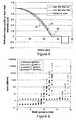
- Figure 6is a graph representing the losses expressed in dB/km as a function of the mode group number. This evolution is presented for both the fibres according to Example 2 and Example T7 and for two wavelengths, which are 850 nm and 1300 nm.
- the points in form of diamondsconcern the losses for the fibre according to Example 2 at the wavelength of 850 nm and the points in form of squares concern the losses for the fibre according to Example 2 at the wavelength of 1300 nm.
- the points in form of trianglesconcern the losses for the fibre according to Example T7 at the wavelength of 850 nm and the points in form of circles concern the losses for the fibre according to Example T7 at the wavelength of 1300 nm.
- the losses of the highest-order core modes of Example 2are much higher than those of Example T7.
- Example 2has losses around 2dB/km and 0.8dB/km at 850 nm and 1300nm, respectively, when Example T7 has losses around 1.9 dB/km at 850 nm and around 0.5 dB/km at 1300 nm.
- the fibre according to the example T7has a fibre quality improved compared to example 2. Indeed, the attenuation as well as the length dependence of overfilled-launch bandwidth, core size and numerical aperture are reduced for a given external cladding position.
- example T8presents the graded-index core and the same trench depth ⁇ n trench and same trench width w2, but the trench is located much closer to the graded-index core, with a width w1 of the inner depressed cladding equal to 0.5 ⁇ m.
- the volume of the trench V trenchis equal to 3581.10 -3 ⁇ m 2 .
- the value of width w1is inferior to 0.6 ⁇ m. Therefore, the example T8 is only shown here as an illustration for the sake of comparison.
- the overfilled-launch bandwidth measured on 1 kmreaches 1690 MHz.km for the wavelength of 850 nm and 590 MHz.km for the wavelength of 1300 nm.
- the value of ⁇ Bis respectively 1.2% and 40.9% for the wavelengths of 850 nm and 1300 nm.
- the core size ⁇ coreis equal to 51.6 ⁇ m.
- the overfilled-launch bandwidthsare penalized compared to example T7.
- the trench position of example T8is not optimized to sufficiently reduce ⁇ B at 1300 nm. Consequently, ⁇ B is much higher than 30%.
- Example T9has same profile as example T7, except the trench depth, i.e. same graded-index core, same external cladding position R4, same inner depressed cladding w1 and same trench width w2.
- the volume of the trench V trenchis equal to 6487.10 -3 ⁇ m 2 . In this specific case, the volume of the trench is superior to 4500.10 -3 ⁇ m 2 . Therefore, the example T9 is only shown here as an illustration for the sake of comparison.
- the overfilled-launch bandwidth measured on 1 kmreaches 3250 MHz.km for the wavelength of 850 nm and 875 MHz.km for the wavelength of 1300 nm.
- the value of ⁇ Bis respectively 2.0% and 24.9% for the wavelengths of 850 nm and 1300 nm.
- the core size ⁇ coreis equal to 53.2 ⁇ m.
- the volume of the trenchis large enough to limit the fibre length dependence on overfilled-launch bandwidth, more especially at 850 nm. But trench depth and the trench volume are too large. As a consequence, too many additional leaky modes are supported by the trench and are not attenuated after 2 m. They disturb the near field pattern used for the core size measurement.
- the core size measured on 2 m using the near field techniqueis superior to 53 ⁇ m, which means that the core size is not equal to graded-index core diameter plus or minus 2 ⁇ m. This introduces a wrong estimation of the graded-index core diameter and fibre length dependence for core size, which are detrimental for connectivity purpose for instance.
- Example T10has same index profile as example T9, but with a trench located further from the graded-index core.
- the volume of the trenchis superior to 4500.10 -3 gm 2 .
- the width w1is superior to 3.5 um. Therefore, the example T10 is only shown here as an illustration for the sake of comparison.
- the overfilled-launch bandwidth measured on 1 kmreaches 1225 MHz.km for the wavelength of 850 nm and 1220 MHz.km for the wavelength of 1300 nm.
- the value of ⁇ Bis respectively 0.4% and 4.3% for the wavelengths of 850 nm and 1300 nm.
- the core size ⁇ coreis equal to 59.9 ⁇ m.
- the volume of the trenchis large enough to limit the fibre length dependence on overfilled-launch bandwidth, at both 850 nm and 1300 nm. But trench volume is too large, too deep and too far from the graded-index core. As a consequence, there are too many additional leaky modes supported by the trench, which are not attenuated after 2 m. They strongly disturb the near field pattern used for the core size measurement. This introduces a wrong estimation of the graded-index core diameter and fibre length dependence for core size, which are detrimental for connectivity purpose, for instance.
- Example T11is another example of structure, which is according to Figure 2 .
- the width w1 of the inner depressed claddingis equal to 1.5 ⁇ m.
- the radius R4is equal to 46.5 ⁇ m in this specific case.
- ⁇ Bis respectively 0.2% and 0.6% for the wavelengths of 850 nm and 1300 nm. It can be noticed that these values of AB are extremely low.
- the core size ⁇ coreis equal to 53.7 ⁇ m, which means that the core diameter is equal to graded-index core diameter plus or minus 2 ⁇ m.
- Example T12is another example of structure, which is according to Figure 2 .
- the width w1 of the inner depressed claddingis equal to 2 ⁇ m.
- the radius R4is equal to 32 ⁇ m in this specific case.
- ⁇ Bis respectively 6.0% and 6.9% for the wavelengths of 850 nm and 1300 nm. It can be noticed that both values of ⁇ B are below 10%.
- the core size ⁇ coreis equal to 49.6 ⁇ m, which means that the core diameter is equal to graded-index core diameter plus or minus 2 ⁇ m.
- Example 3corresponds to a down-doped multimode fibre with same core dimensions and exhibiting the same properties with regards to the graded-index core, but no trench ( Figure 1 ).
- the radius R4 of example 3is 41 ⁇ m.
- the external claddingis located further than the external cladding of example T12 to obtain a parameter ⁇ B inferior to 10% at a wavelength of 850 nm and inferior to 30% at a wavelength of 1300 nm.
- the external cladding of example 3is located 9 ⁇ m further compared to example 12.
- manufacturing a depressed fibre with an external cladding positioned closer to the coreis easier and cheaper. Therefore, the manufacturing costs for fibre of example T12 are reduced without deteriorating the fibre characteristics (overfilled-launch bandwidths, core size, numerical aperture, attenuation).
- examples T1, T2, T4, T5, T7, T11 and T12are multimode optical fibres comprising a core region with a first radius R1 and a profile alpha with a maximum optical core index, an inner depressed cladding extending radially from the first radius R1 to a second radius R2, a trench extending from the second radius R2 to a third radius R3, an outer depressed cladding extending radially from the third radius R3 to a fourth radius R4 and an external cladding extending radially from the fourth radius R4.
- the volume of the trench V trenchis comprised between 1650x10 -3 ⁇ m 2 and 4500 x10 -3 ⁇ m 2
- the difference in distance between the second radius R2 and the first radius R1is comprised between 0.6 ⁇ m and 3.5 ⁇ m
- the fourth radius R4is comprised between 30 ⁇ m and 47 ⁇ m
- the difference in distance between the third radius R3 and the second radius R2may be comprised between 2.4 ⁇ m and 10 ⁇ m.
- fibreshave low loss depressed-graded index 50 ⁇ m multimode fibre in which the leakage losses are managed to allow an outer core radius below 47 ⁇ m.
- the overfilled-launch bandwidth at a wavelength of 850 nmis superior to 500 MHz.km, and preferably superior to 1000 MHz.km.
- the overfilled-launch bandwidth at a wavelength of 1300 nmmay be superior to 500 MHz.km, and preferably superior to 1000 MHz.km.
- the core size at 850 nm measured at 2 m with the near-field techniqueis equal to the first radius plus or minus 2 ⁇ m.
- such fibresusually exhibit a decrease in overfilled-launch bandwidth between the bandwidth measured on 500 m and the bandwidth measured on 8 km at a wavelength of 850 nm inferior to 10%.
- the decrease in overfilled-launch bandwidth for these fibres between the overfilled-launch bandwidth measured on 500 m and the overfilled-launch bandwidth measured on 8 km at a wavelength of 1300 nmmay also be inferior to 30%.
- optical fibreenables to reduce the manufacturing costs by bringing the external cladding closer to the graded-index core, without deteriorating the fibres characteristics (overfilled-launch bandwidths, core size, numerical aperture, attenuation).
Landscapes
- Physics & Mathematics (AREA)
- General Physics & Mathematics (AREA)
- Optics & Photonics (AREA)
- Chemical & Material Sciences (AREA)
- Dispersion Chemistry (AREA)
- Manufacture, Treatment Of Glass Fibers (AREA)
- Optical Couplings Of Light Guides (AREA)
- Optical Fibers, Optical Fiber Cores, And Optical Fiber Bundles (AREA)
- Mechanical Coupling Of Light Guides (AREA)
Description
- The present invention relates to the field of optical fibre transmissions, and more specifically a depressed graded-index multimode optical fibre with a trench and a method to manufacture such fibre.
- In standard fashion, an optical fibre is composed of an optical core the function of which is to transmit and optionally amplify an optical signal, and an optical cladding the function of which is to confine the optical signal within the core. To this end, the refractive indices of the core ncore and the cladding ncladding are such that ncore>ncladding.
- The index profile of a fibre denotes the graph of the function which associates the refractive index with the radius of the fibre. In standard fashion, the distance to the centre of the fibre is shown on the x-axis, and on the y-axis, the difference between the refractive index and the refractive index of the fibre cladding. Generally the index profile is qualified according to its appearance. Thus the index profile is described in terms of a "step", "trapezium", "triangle", or "alpha" for graphs which have step, trapezium, triangle, or graded shapes respectively. These curves are representative of the theoretical or set profile of the fibre, while the manufacturing constraints of the fibre may result in a substantially different profile.
- Two main types of optical fibres exist, multimode fibres and single mode fibres. In a multimode fibre, for a given wavelength, several optical modes are propagated simultaneously along the fibre, whereas in a single mode fibre modes of a higher order are strongly attenuated. The typical diameter of a single mode or multimode optical fibre is 125 µm. The core of a multimode fibre typically has a diameter of 50 µm or 62.5 µm, whereas the core of a single-mode fibre generally has a diameter of approximately 6 µm to 9 µm. The multimode systems are less expensive than the single mode systems, as the sources, connectors, and maintenance are of lower cost.
- Now, in a multimode fibre, the bandwidth is linked to the intermodal dispersion. In fact, the bandwidth results from the difference between the propagation times, or group delay times, of the modes along the fibre. In particular, for the same propagation medium (in a step index multimode fibre), the different modes have group delay times which are different. This results in a time lag between the pulses propagating in different radial directions. A time lag between the individual pulses causes a broadening of the resulting light pulse which risks being superimposed onto a following pulse, and thus reduces the data rate supported by the fibre. The bandwidth is therefore directly linked to the group delay time of the optical modes propagating in the multimode core of the fibre. In order to guarantee a broad bandwidth, the group delay times of all the modes should be identical; i.e. for the intermodal dispersion to be zero, or at least minimized, for a given wavelength.
- In order to reduce the intermodal dispersion in a multimode fibre, it has been proposed to produce graded-index fibres with an "alpha" core profile. Such a fibre has been used for many years and its characteristics have been described in particular in "Multimode theory of graded-core fibres" by D. Gloge et al., Bell system Technical Journal 1973, pp 1563-1578, and summarized in "Comprehensive theory of dispersion in graded-index optical fibres" by G. Yabre, Journal of Lightwave Technology, February 2000, Vol. 18, No. 2, pp 166-177.
- A fibre having a graded-index profile or alpha-index profile - these two terms are equivalent - is a fibre with a graded-index core surrounded by cladding with a constant optical index. The α graded-index profile follows a power law of parameter α which can be defined by a relationship between the index value n at a point as a function of the distance r from this point to the centre of the fibre:

- withα ≥ 1 (α → ∞ corresponding to the development of the index of a step-index fibre);
- nmax, the maximum optical index of the core of the multimode fibre;
- r1, the radius of the core of the multimode fibre; and

where nmin is the minimum index of the multimode core, generally corresponding to the index of the cladding (most often made of silica). - A graded-index multimode fibre therefore has a core profile with a rotational symmetry such that in any radial direction the value of the index decreases continuously from the centre of the fibre to its periphery. When a multimode light signal propagates in such a core having a graded index, the different modes experience a different propagation medium, which affects their speed of propagation differently. By adjusting the value of the parameter α, it is therefore possible to obtain a group delay time which is virtually equal for all the modes and therefore a reduced intermodal dispersion. In such multimode fibres having an adjusted α parameter, bandwidth can be maximized for communication data at a given wavelength, or optimized to provide a high bandwidth over a range of wavelengths (e.g. between 850 nm and 1300 nm).
- Multimode fibres have been the subject of international standardization under standard ITU-T G.651.1 which in particular defines criteria for bandwidths, numerical aperture, core diameter which relate to the requirements for compatibility between fibres. The standard OM3 has been adopted to satisfy high-speed applications (greater than 1GbE) over long distances (greater than 300 m). With the development of high-speed applications the average core diameter has been reduced from 62.5 µm to 50 µm. Such multimode fibres with a large bandwidth are in particular intended to be used for short distances in a local area network (LAN).
- Another increasing interest in using multimode fibres concerns their use in nuclear power plants and other radiation-rich environments, such as particle acceleration laboratories and satellites. For example, optical fibres may be used in optical data communication links, distributed sensors, plasma diagnostics, and instrumentation systems. In such applications, optical fibres typically transmit signals through noisy electromagnetic environments, high gamma ray dosages and/or dosage rates, and high neutron fluencies. Signals transmitted via optical fibres typically undergo optical losses (i.e., attenuation) that accumulate over the distance traveled. These transmission losses increase substantially when the optical fibre is subjected to ionizing radiation, such as beta, alpha, gamma, and/or X-rays. Presence of Germanium and Phosphorus in the silicate glass matrix promotes the formation of defects in the silicate glass under irradiation. One solution to reduce radiation-induced attenuation consists in using Phosphorus-free and Germanium-free fibre.
- Another promising application for multimode fibre optics is distributed temperature sensing in geothermal wells. Temperature profile obtained just after drilling can provide guidance as how to best harness heat generated by the well. Additionally, long-term thermal monitoring of a power-producing geothermal well is needed to optimize its running. For such use to be practical, however, requires that the optical fibre to be placed in the geothermal well can survive to harsh hydrogencontaining downhole environment for a period measured in years. Transmission anomalies are found to relate to the formation of OH ions in the silicate glass matrix of the optical fibres. The likely degradation mechanism is that hydrogen in the hot downhole environment diffuses into the fibre and reacts with the oxygen of the silicate glass to form OH ions. Presence of Germanium and Phosphorus in the silicate glass matrix promotes the formation of OH ions. One solution consists in using Phosphorus-free and very low Germanium content fibres, combined with barrier coatings.
- Phosphorus-free and Germanium-free multimode fibres have conventionally a graded-index alpha profile and a cladding in silica doped with fluorine to reduce its refractive index. Graded-index core and cladding are therefore depressed compared to pure silica index.
WO2011/109263A is prior art under Article 54(3) EPC and discloses a large core multimode optical fiber with high numerical aperture. Said fiber comprises a core region having a radius of greater than 30 microns and a cladding region surrounding and directly adjacent to the core region. The cladding region comprising a depressed-index annular portion comprising a depressed relative refractive index.- In a known wayper se, an optical fibre is made by drawing a preform on a fibre-drawing tower. A preform for example comprises a primary preform consisting of a very high quality glass tube making up a portion of the cladding and core of the fibre. This primary preform is then over cladded or sleeved in order to increase its diameter and to form a preform, which may be used on a fibre-drawing tower. The scaled fibre-drawing operation consists of placing the preform vertically in a tower and of drawing a fibre strand from the end of the preform. For this, a high temperature is locally applied at one end of the preform until the silica is softened; the fibre-drawing rate and the temperature are then permanently monitored during the fibre drawing as they determine the diameter of the fibre. The geometry of the preform should perfectly observe the ratios of the refractive indexes and of the core and cladding diameters of the fibre so that the drawn fibre has the required profile.
- The primary preform may consist of a substrate tube, generally in quartz, in which one or more layers of doped and/or undoped silica have been deposited to form the core and an inner cladding of the fibre. Deposition techniques inside a substrate tube include MCVD (Modified Chemical Vapor Deposition), FCVD (Furnace Chemical Vapor Deposition) or PCVD (Plasma Chemical Vapor Deposition). After depositing the layers corresponding to the core and the inner cladding, the tube is closed onto itself during an operation called collapsing.
- Component deposition is commonly referred to by the expression "doping", i.e., "dopants" are added to the silica in order to change its refractive index. Thus, germanium (Ge) or phosphorus (P) increases the refractive index of silica; they are often used for doping the central core of the fibre. Moreover, fluorine (F) or boron (B) lowers the refractive index of silica; fluorine is often used for forming depressed claddings.
- Making a primary preform with highly and large depressed graded-index core and cladding are delicate. It requires fluorine in both the central region and in the cladding. Indeed, fluorine for instance is poorly incorporated in heated silica beyond a certain temperature whereas a high temperature is required for making glass. PCVD technique can be efficiently used to produce depressed cladding inside a deposition tube. Such a manufacturing technique is described in documents
US RE 30,635 andUS 4,314,833 ; it allows fluorine to be significantly incorporated into silica in order to form highly depressed claddings. A deposition tube, made of silica either pure or doped with fluorine, is provided and mounted in a glasswork tower. The tube is then set into rotation and a gas mixture of silica and dopants are injected into the tube. The tube crosses a microwave cavity in which the gas mixture is heated locally. The microwave heating generates plasma by ionization of the gases injected into the tube and the ionized dopants highly react with the silica particles, causing deposition of doped silica layers inside the tube. The high reactivity of the dopants, generated by the microwave heating, enables a high concentration of dopants to be incorporated into the silica layers. Figure 1 illustrates a set index profile of a conventional depressed graded-index multimode fibre (DGIMMF). The optical fibre includes a central core that is surrounded by an outer cladding (e.g., an outer optical cladding). For reasons of cost, the outer cladding is typically made of natural silica, but it may also be made of doped silica. As shown, the optical fibre's central core is a glass based central core having an alpha index profile (i.e., a graded-index profile) and an outer radius R1. The central core is typically doped with fluorine (F) to reduce the refractive index of the silica. Typically, the graded-index core and the inner cladding are made by deposition inside a substrate tube and the outer cladding is made of the substrate tube used for making the primary preform and of the over clad or sleeve used to reach to requested diameter ratio.- In the above-described structure, with an outer cladding having substantially the same refractive index as the top of the α graded-index core, the different modes sustained by the multimode fibre are not completely guided and show additional losses, called leakage. Leakage losses are due to partial reflection of the modes having their effective indexes (their real part) lower than that of the outer cladding at the inner interface of the outer cladding. Lower the effective indexes of the mode are, higher the leakage losses are. Consequently, leakage losses will be higher for the highest order modes. To minimize these leakage losses, the percentage of energy propagating in the outer pure silica cladding must be reduced. The inner depressed cladding silica must be sufficiently extended to ensure good confinement of the optical signal in the graded-index core and an acceptable level of leakage losses.
- High leakage losses are detrimental because they lead to dramatic core size and numerical aperture reduction. This can be critical for backward compatibility with standard multimode fibres and for connectorization purpose.
- In addition, highest attenuation of the highest order modes will lead to suppress the modes having the largest group time delay differences. As a consequence, fibre will suffer from a strong fibre length dependence on bandwidth, which can be problematic for fibre characterization purpose.
- MCVD, FCVD and PCVD techniques are satisfactory to obtain good quality core and highly depressed large inner cladding but is costly whenever large capacity preforms are sought. Notably, use of CVD techniques makes it possible to limit attenuation and notably the attenuation at 1383 nm due to the OH peak.
- Capacity of a preform is defined as the quantity of optical fibre length, which can be drawn from this preform. The greater the diameter of the preform is, the greater this capacity. To reduce manufacturing costs, it is desirable to provide long lengths of linear fibre drawn from one same preform. It is therefore sought to fabricate preforms of large diameter while complying with the above-mentioned constraints regarding the diameters of the central core and the depressed inner cladding. Therefore, the smaller the ratio of "outer radius of depressed cladding" over "graded-index core radius" is, the larger the diameter of the preform is and the lower the manufacturing cost is. Furthermore, reducing the width of the depressed cladding allows putting down a larger graded-index core, which helps to improve the accuracy of the alpha-shape profile.
- One solution to reduce the width of the depressed cladding consists in adding a depressed trench in the inner cladding between the graded-index core and the outer cladding.
EP 2 312 350 A1 andUS 2011/0085770 A1 already propose to add a trench in the inner depressed cladding to reduce leakage losses and thus to bring the outer cladding closer to the core. But this application concerns single-mode fibres for which problematic are different. Only LP01, LP11 and LP02 modes need to be managed without constraints on bandwidth, core size and numerical aperture. Furthermore, ratio of "outer radius of depressed cladding" over "core radius" is much larger than in a multimode refractive index profile.- The documents
WO-A-2008/085851 andUS-A-2008/0166094 describe multimode fibres having a graded-index core surrounded by a depressed-index annular portion between the core and the optical cladding. This depressed-index annular portion trench is added to reduce the bending losses of a graded-index multimode fibre. - Typically, the solutions disclosed in the documents
WO-A-2008/085851 andUS-A-2008/0166094 , do not concern depressed graded-index multimode fibres. Applying the proposed solutions to only fluorine-doped profiles cannot allow minimizing the leakage losses when cladding is composed of a depressed cladding and of an outer cladding made of natural silica. - The documents
EP-A-2 166 386 andUS-A-2010/0067858 describe multimode fibres having a graded-index core and an inner cladding adjacent to the graded-index core surrounded by a depressed-index annular portion between the core and the optical cladding. This depressed-index annular portion trench is added to reduce the bending losses of a graded-index multimode fibre. - Typically, the embodiments disclosed in the documents
EP2166386A1 andUS 2010/0067858 A1 , do not concern depressed graded-index multimode fibres. Applying the proposed embodiments to only fluorine-doped profiles cannot allow minimizing the leakage losses when cladding is composed of a depressed cladding and of an outer cladding made of natural silica. - Document
EP-A-2 220 524 describes multimode fibres having a graded-index core and an inner cladding adjacent to the graded-index core surrounded by a depressed-index annular portion between the core and the optical cladding. This depressed-index annular portion trench is added to reduce the bending losses of a graded-index multimode fibre. - Furthermore, the fibres disclosed in the document
EP-A-2 220 524 , do not concern depressed graded-index multimode fibres. Applying the proposed solutions to only fluorine-doped profiles cannot allow minimizing the leakage losses when cladding is composed of a depressed cladding and of an outer cladding made of natural silica. - Moreover the addition of a depressed trench results in the appearance of additional leaky modes that will co-propagate with the desired leaky modes. The larger the depressed trench is, the lower the leakage losses are. On the other hand, the deeper the depressed trench is, the higher the number of leaky modes is.
- These additional leaky modes have effective refractive indices, which are lower than those sustained by the depressed graded-index core. This leads to an increase in the numerical aperture measured on 2 m by the far field pattern in the graded-index fibres comprising a depressed trench, in comparison with the numerical aperture measured in the graded-index fibres without a depressed trench according to the well-known standardized IEC 60793-1-43 method. Numerical aperture of GIMMF with trench can look larger than expected by the value of the parameter Δ of its graded-index core.
- In addition, the leaky modes can contribute to corrupt the core size derived from the near field pattern measured under overfilled launch (OFL) at the output of a 2m long sample with IEC 60793-1-20 Method C. Core size of GIMMF with trench can look larger than expected by its graded-index core width.
- Corrupted numerical aperture and core size measurements may lead to wrong conclusions regarding the core size and the value of the parameter Δ of the refractive index profile, which are of main importance for connectivity purpose because they determine the number and the shape of the guided modes. Such a difference in number and in shape of the guided mode between two different graded-index fibres can lead to mode mismatching and therefore to high splice losses or connectivity losses.
- In addition, it can be noticed that multimode fibres with cores with indexes close to that of Silica and down-doped index claddings provides multiple advantageous features compared to standard multimode fibres with up-doped cores and Silica claddings. Among improved radiation and Hydrogen resistance features, low losses and large bandwidths may be mentioned. However, these structures are difficult to make and costly a highly depressed cladding has to be deposited. Usually the index difference with Silica may reach 16x10-3. Thus, the technique PCVD is often used. This technique is an inside deposition process (like the methods MCVD and FCVD) that allows to reach such negative index differences. However the Silica substrate tube has to be put far from the core in order to prevent the modes from leaking and thus experiencing high (leakage) losses, which yields to small-diameter core-rods.
- A need therefore exists for a fibre, which enables to reduce the width of the down-doped cladding that has to be deposited inside the silica Substrate tubes without increasing the leakage losses of the modes and without deteriorating the other propagation characteristics of the fibre such as bandwidths, core size or numerical aperture.
- For this purpose, it is proposed a multimode optical fibre according to
claim 1. - According to preferred embodiments, the fibre may further comprise one or any combination of the following features:
- the difference in index between the maximal optical core index and the external cladding is comprised between -1.0 x 10⁻³ and 0.8x10⁻³.
- the difference in index between the outer depressed cladding and the external cladding is comprised between -18 x10-3 and -12x10-3.
- the difference in distance between the third radius and the second radius is comprised between 2.4 µm and 10 µm.
- the decrease in overfilled-launch bandwidth between the overfilled-launch bandwidth measured on 500 m and the overfilled-launch bandwidth measured on 8 km at a wavelength of 850 nm is inferior to 10%.
- the decrease in overfilled-launch bandwidth between the overfilled-launch bandwidth measured on 500 m and the overfilled-launch bandwidth measured on 8 km at a wavelength of 1300 nm is inferior to 30%.
- the core size at 850 nm measured at 2m with the near-field technique is equal to the first radius plus or minus 2 µm.
- the difference in index between the trench and the outer depressed cladding is comprised between -6 x10⁻³ and -2x10⁻³.
- the difference in index between the trench and the external cladding is comprised between -24 x 10-3 and -14
x 10-3. - the difference in index between the inner depressed cladding and the outer depressed cladding is comprised between -2x10⁻³ and 2x10⁻³.
- alpha is comprised between 1.9 and 2.1.
- the overfilled-launch bandwidth at a wavelength of 850 nm is superior to 500 MHz.km, and preferably superior to 1000 MHz.km.
- the overfilled-launch bandwidth at a wavelength of 1300 nm is superior to 500 MHz.km, and preferably superior to 1000 MHz.km.
- It is also proposed a method for manufacturing an optical fibre as previously described.
- Further features and advantages of the invention will appear from the following description of embodiments of the invention, given as non-limiting examples, with reference to the accompanying drawings listed hereunder.
Fig. 1 shows an index profile of a depressed graded-index fibre without depressed trench in the inner cladding;Fig. 2 shows an index profile of an example of fibre according to the invention;Fig. 3 shows the evolution of the core size with the fibre length;Fig. 4 andFig. 5 show the evolution of the radius of the refractive index profile and of near field intensity at several distances respectively for examples T4 and T6;Fig. 6 shows a graph of losses as a function of the group mode number for several fibres.- The idea of the invention is to reduce the leakage losses of the down-doped MMF by adding a trench between a graded-index core and an external cladding. Basically, the biggest the trench is, the lowest the leakage losses are. But, it also allows additional "leaky modes" to co-propagate with the usual guided modes of the core. These "leaky modes" can significantly disturb the near field pattern observed at the output of a 2m sample of a fibre sample and overestimate the graded-index core size. In addition, these additional leaky modes can significantly disturb the far field pattern observed at the output of a 2m sample of a fibre sample and overestimate the index difference of the graded-index.
- The position and dimensions of the trench has to be chosen with care in order to minimize the leakage losses of the core modes, to limit the presence of additional "leaky modes" due to the trench by maximizing their leakage losses and to avoid degradation of the bandwidth. The reduction of leakage losses in the core prevents reduction of core-size and/or numerical aperture as well as disturbances of the bandwidth over length. Limiting the presence of additional "leaky modes" due to the trench is important in so far as they can propagate over several meters and can lead to wrong estimation of the graded-index core dimensions. As the core dimensions are relevant for assessing the performance for connectivity, a good control of the "leaky modes" is therefore critical for connectivity purpose.
- Therefore, a dedicated architecture of a trench-assisted depressed graded index multimode fibre is proposed.
Figure 2 is an index profile of an example of fibre having such specific architecture. The fibre comprises a core region with a first radius R1 and a first inner cladding extending radially from the first radius R1 to a second radius R2. The optical index of the inner cladding has a substantially constant over the whole width of the optical cladding. The width w1 corresponds to the difference in size between the second radius R2 and the first radius R1. Preferably, the width w1 of the first inner cladding is comprised between 0.6 µm and 3.5 5 µm. More preferably, the width w1 is comprised between 0.8 µm and 2.5 µm. This enables to provide the fibre according to the invention with improved properties in term of core size, without deteriorating the bandwidth. - The core has an alpha optical index profile with respect to the inner optical cladding. The parameter alpha can be comprised between 1.9 and 2.1. According to the specific example of
Figure 1 , the value of alpha is 1.95. The core of the fibre according to the example ofFigure 1 has a radius R1 typical of a multimode fibre. The radius of the core can be, for example, a maximum of 36.25 µm. Preferably, the radius R1 of the core can be comprised between 23 µm and 27 µm, and preferably 25.5 µm. - The difference in index Δn1 between the maximal optical core index and the external cladding may be comprised between -1.0 x10⁻³ and 0.8x10⁻³.
- The fibre further comprises a trench extending from the second radius R2 to a third radius R3 and an outer depressed cladding extending radially from the third radius R3 to a fourth radius R4. Beyond the fourth radius R4, an external cladding extends radially. The external cladding is preferably derived from the substrate tube in which deposition of glass layers took place during preform manufacturing.
- The trench can be defined by its width w2 and its depth Δntrench. The width w2 corresponds to the difference in distance between the third radius R3 and the second radius R2. Preferably, the width w2 of the trench is comprised between 2.4 µm and 10 µm. The depth Δntrench corresponds to the difference in index between the trench and the outer depressed cladding. Such difference in index between the trench and the outer depressed cladding is comprised between - 6x10⁻³ and - 2x10⁻³.
- In addition, the trench can be defined by its volume Vtrench. The volume of the trench Vtrench can be expressed mathematically as:

- The volume of the trench is comprised between 1650x10-3 µm2 and 4500 x10-3 µm2. More preferably, the volume of the trench is comprised between 3000x10-3 µm2 and 4000x10-3 µm2. This enables to provide the fibre according to the invention with improved properties. Notably, such fibres will have low loss depressed-graded index 50 µm multimode fibre in which the leakage losses are managed to allow a reduced outer core radius, resulting in an easier manufacturing with the other properties of the fibre maintained.
- The relative difference in index between the different areas of the fibre according to
Figure 1 can be further specified. The difference in index Δn2 between the outer depressed cladding and the external cladding may be comprised between - 18x10-3 and -12.10-3. This means the difference in index between the trench and the external cladding may be comprised between -24 x10-3 and -14 x10-3. This difference in index between the trench and the external cladding corresponds to Δntrench + Δn2. - In alternative, the difference in index between the inner depressed cladding and the outer depressed cladding may be comprised between -2 x10⁻³ and 2x10⁻³. This difference in index between the inner depressed cladding and the outer depressed cladding corresponds to Δninner - Δn2. Thus, this feature can be expressed mathematically as Δninner= Δn2 ± 2x10⁻³.
- For the fibre according to
Figure 2 , the fourth radius R4 is comprised between 30 µm and 47 µm. Preferably, the radius R4 may be comprised between 30 µm and 45 µm. - Compared to a down-doped multimode fibre with same core dimensions and same external cladding position (i.e radius R4 comprised between 30 µm and 45 µm) but no trench (
Figure 1 ), a multimode optical fibre having the structure ofFigure 2 , and more specifically the combination of a volume of the trench comprised between 1650 x 10-3 µm2 and 4500 x 10-3 µm2, , a difference in distance between the second radius R2 and the first radius R1 comprised between 0.6µm and 3.6µm and difference in distance between the third radius R3 and the second radius R2 comprised between 2 µm and 10 µm, is a fibre having a fibre quality improved. Indeed, the attenuation as well as the fibre length dependence of bandwidths, core size and numerical aperture are reduced for a given external cladding position. Furthermore, such optical fibre enables to reduce the manufacturing costs by bringing the external cladding closer to the graded-index core, without deteriorating the fibres characteristics (bandwidths, core size, numerical aperture, and attenuation) compared to the down-doped multimode fibre with same core dimensions but no trench. - These advantages will appear more clearly by reference to tables I and II which compare the properties of different examples of profiles. All the examples described in Tables I and II have similar graded-index central core. But different external cladding positions and various trench characteristics are presented.
- Table I gives the different parameters of the architecture chosen for the twelve examples. For each example, the different values given are the value of the fourth radius R4, the value of the first radius R1, the value of Δn1-Δn2, the depth of the trench Δntrench, the width w1 of the inner depressed cladding, the width w2 of the trench and the volume of the trench. For each example, the value of alpha is fixed to 1.96. In addition, in the present examples of Table I, the value of Δninner is equal to Δn2.
Table I: Characteristics of the parameters of the index of several examples. Profiles R4 (µm) R1 (µm) Δn1 Δn1-Δn2 (10-3) Δntrench (10-3) w1 (µm) w2 (µm) Trench volume (10-3 µm3) Example 1 40 25.5 -0.6 15.8 0 *n.a n.a 0 Example T1 40 25.5 -0.6 15.8 -2 1 8.5 3285 Example T2 40 25.5 -0.6 15.8 -3 1 7.5 4276 Example T3 40 25.5 -0.6 15.8 -3 1 3 1583 Example T4 40 25.5 -0.6 15.8 -4 0.8 5 3619 Example T5 40 25.5 -0.6 15.8 -4 1.5 5 3707 Example T6 40 25.5 -0.6 15.8 -4 7 5 4398 Example 2 35 25.5 -0.6 15.8 0 n.a n.a 0 Example T7 35 25.5 -0.6 15.8 -4 1.5 5 3707 Example T8 35 25.5 -0.6 15.8 -4 0.5 5 3581 Example T9 35 25.5 -0.6 15.8 -7 1.5 5 6487 Example T10 35 25.5 -0.6 15.8 -7 5 4.5 6482 Example T11 46.5 26.2 -0.9 15.7 -3.6 1.5 5.5 3701 Example T12 32 25 -0.6 15.8 -5 2 4.5 3707 Example 3 41 25 -0.6 15.8 0 n.a n.a 0 (*) n.a : not applicable - Table II provides the properties of several examples. The Overfilled-launch bandwidth is given for two wavelengths: 850 nm and 1300 nm and measured at 1 km (this can be noted by the acronym OFL-BW). Overfilled-launch bandwidth is the originally standardized fibre bandwidth measurement method in which the overfilled-launch bandwidth measurement test setup is defined by the FOTP-204 standard. Therefore, the source used launches light uniformly into all modes of the multimode fibre. All the modes being uniformly launches, this measurement method is particularly accurate to detect any leakage losses, especially in the highest order modes having the lowest effective indexes and so, the highest leakage losses when overfilled-launch bandwidth of one fibre is measured over different fibre lengths. In order to improve the reproducibility of bandwidth measurements, it has been chosen to filter the overfilled-launch modes with a large core step index fibre having a core diameter larger than 55 µm and a numerical aperture of 0.210 ± 0.01. The large core step index fibre should be 2 m ± 0.2 m in length and coupled in the fibre under test. Therefore, the overfilled-launch bandwidth measured over 500 m is compared with the overfilled-launch bandwidth measured over 8 km. The difference bandwidth is expressed in relative percentage and corresponds to the loss in bandwidth between the bandwidth measured at 500 m and the bandwidth measured at 8 km. In the remainder of the description, this overfilled-launch bandwidth difference will be noted ΔB. This bandwidth difference ΔB can be used as a key indicator of leakage losses. This value of ΔB will be given for two wavelengths, which are 850 nm and 1300 nm. The core size measured according to the well-known standardized IEC 60793-1-20 Method C, without curve fitting i.e. directly from the measured pattern at the k level, with k=2.5% is also given at the wavelength of 850 nm. This method consists in determining the cross-sectional diameter of the graded-index core of the optical fibre by analyzing the near field light distribution - also called near field pattern - on a cross-section at the end of a 2m-long fibre under OFL and by calculating the core diameter with or without curve fitting. In the remainder of the description, this core size is noted Φcore. This value should be compared to the graded-index core diameter.
Table II: Properties of several examples. Profiles OFL-Bandwidth at 1 km ΔB Core size (µm) 850 nm, 2m 850 nm MHz.km 1300 nm MHz.km 850 nm 1300 nm Example 1 1850 1450 4.0% 31.2% 50.8 Example T1 1900 1660 0.5% 13.0% 52.6 Example T2 4170 1700 0.1% -0.9% 52.4 Example T3 3250 1830 10.0% 5.5% 51.3 Example T4 2225 640 0.2% 22.5% 51.5 Example T5 2010 1990 0.2% 9.3% 52.7 Example T6 1120 1035 0.9% 5.1% 62.2 Example 2 1970 2110 11.3% 39.6% 49.7 Example T7 2015 2140 2.9% 3.7% 52.7 Example T8 1690 590 1.2% 40.9% 51.6 Example T9 3250 875 2.0% 24.6% 53.2 Example T10 1225 1220 0.4% 4.3% 59.9 Example T11 3341 1600 0.2% 0.4% 53.7 Example T12 3096 1834 6.0% 6.9% 49.6 Example 3 2025 1148 1.2% 11.1% 49.9 - Example T1 is an example of structure which is according to
Figure 2 . In this case, the first radius R1 is equal to 25.5 µm and the fourth radius R4 is equal to 40 µm. The value of Δn1-Δn2 is equal 15.8x10⁻³. The trench has a depth equal to Δntrench = -2.10-3, a volume Vtrench of 3285.10-3 µm2 and a width w2 of 8.5 µm. In addition, the trench is located at a distance w1=1 µm from the end of the core. - Different properties are given in Table II. More specifically, the overfilled-launch bandwidth measured on 1 km reaches 1900 MHz.km for the wavelength of 850 nm and 1660 MHz.km for the wavelength of 1300 nm. In addition, the value of ΔB is respectively 0.5% and 13.0% for the wavelengths of 850 nm and 1300 nm. It can be noticed that the value of ΔB is below 10% for the wavelength of 850 nm and below 30% for the wavelength of 1350 nm. Furthermore, the core size Φcore is equal to 52.6 µm.
- Example T1 should be compared to example 1. Example 1 corresponds to a down-doped multimode fibre with same core dimensions and external cladding positioned at same radius from the centre of the core, but no trench. Accordingly, in the case of example 1, the values of the first radius R1, the fourth radius R4 and of Δn1-Δn2 are the ones of example T1, whereas, as expected, the values Δntrench and the volume of the trench Vtrench, are equal to 0.
- In addition, the fibre according to example 1 exhibits an overfilled-launch bandwidth measured on 1 km, which reaches 1850 MHz.km for the wavelength of 850 nm and 1450 MHz.km for the wavelength of 1300 nm. In addition, the value of ΔB is respectively 4.0% and 31.2% for the wavelengths of 850 nm and 1300 nm. Furthermore, the core size Φcore is equal to 50.8 µm.
- Thus, the fibre according to example T1 has a value of ΔB, which is reduced at both 850 nm and 1300 nm wavelengths. In addition, the add of trench do not penalize the overfilled-launch bandwidth, since even better overfilled-launch bandwidth measured over 1 km for the wavelengths of 850 nm and 1300 nm than the fibre according to example 1 are obtained. Furthermore, effect of additional leaky-modes sustained by the trench is limited, since core size measured on a 2 m fibre does not differ of more than 2 µm from the diameter of the graded-index core.
- The difference between the fibre according to example T1 and example 1 can be explained by the difference of structure between the two fibres. Indeed, the external cladding being too close to the graded-index core in the case of example 1, the leakage losses of the highest-order core modes are too high. Consequently, the highest-order core modes are strongly attenuated with fibre length, and do not contribute anymore to the modal bandwidth calculation. Number of modes sustained by the fibre being strongly reduced with fibre length, the overfilled-launch bandwidth will increase with fibre length whereas core size will decrease. So the overfilled-launch bandwidth becomes strongly dependent on fibre length, especially at 1300 nm (superior to 30%) where leakage losses are higher. Furthermore, we can expect higher attenuation than for a fibre with optimized trench.
- Thus, example T1 is a fibre having a fibre quality improved compared to example 1. Indeed, the attenuation as well as the length dependence of bandwidths, core size and numerical aperture are reduced for a given external cladding position.
- Example T2 is an example of structure, which is according to
Figure 2 . Compared to example T1, example T2 presents the same features except for the trench. According to example T2, the trench has a depth equal to Δntrench = -3.10-3, a volume Vtrench of 4276.10-3 µm2 and a width w2 of 7.5 µm. The distance between the graded-index core and the trench is not modified. - Different properties of the fibre according to example to T2 are given in Table II. More specifically, the overfilled-launch bandwidth measured over 1 km reaches 4170 MHz.km for the wavelength of 850 nm and 1700 MHz.km for the wavelength of 1300 nm. In addition, the value of AB is respectively 0.1% and -0.9% for the wavelengths of 850 nm and 1300 nm. It can be noticed that the value of ΔB is below 10% for the wavelength of 850 nm and below 30% for the wavelength of 1300 nm. Furthermore, the core size Φcore is equal to 52.4 µm.
- Example T2 should also be compared to example 1. The fibre according to example T2 has a value of ΔB, which is reduced at both 850nm and 1300nm wavelengths. In addition, adding a trench does not penalize the overfilled-launch bandwidth, since even better bandwidth measured over 1 km for the wavelengths of 850 nm and 1300 nm than the fibre according to example 1 are obtained. Furthermore, effect of additional leaky-modes sustained by the trench is limited, since core size measured on a 2 m fibre does not differ of more than 2 µm from the diameter of the graded-index core. Therefore, similarly to the example T1, the fibre according to the example T2 has a fibre quality improved compared to example 1. Indeed, the attenuation as well as the length dependence of overfilled-launch bandwidth, core size and numerical aperture are reduced for a given external cladding position.
- Compared to Example T2, in the structure according to example T3, the width w2 of the trench is much smaller and is equal to 3 µm whereas the trench depth and its distance from the graded-index core are unchanged. Consequently, the volume of the trench is smaller too and equal to 1583.10-3 µm2. In this specific case, the value of the third radius R3 is 29.5 µm. Therefore, the example T3 is only shown here as an illustration for the sake of comparison.
- In the case of Example T3, the value of ΔB is respectively 10.0% and 5.5% for the wavelengths of 850 nm and 1300 nm. The value of ΔB is so strongly increased for the wavelength of 850 nm compared to examples T1 and T2 having the same external cladding position but larger trench volume. Such volume of a trench is not sufficient to limit the leakage losses of the highest-order core modes, especially at 850nm. As a consequence, the fibre suffers from strong fibre length dependence of overfilled-launch bandwidth.
- Example T4 is another example of structure, which is according to
Figure 2 . The trench has a depth equal to Δntrench = -4.10-3, a volume Vtrench of 3619.10'3 µm2 and a width w2 of 5 µm. The width w1 of the inner depressed cladding is equal to 0.8 µm. - By referring to Table II, in the case of Example T4, the overfilled-launch bandwidth measured over 1 km reaches 2225 MHz.km for the wavelength of 850 nm and 640 MHz.km for the wavelength of 1300 nm. In addition, the value of ΔB is respectively 0.2% and 22.5% for the wavelengths of 850 nm and 1300 nm. It can be noticed that the value of ΔB is below 10% for the wavelength of 850 nm and below 30% for the wavelength of 1300 nm. Furthermore, the core size Φcore on 2 m using the near field technique is equal to 52.4 µm.
- Example T4 should be compared to example 1. The value of ΔB is reduced for both wavelengths and more especially at 850 nm Therefore, the leakage losses have been particularly reduced at 850 nm, compared to same fibre without trench.
- The comparison between the core size for the examples 1 and the example T4 can be further refined by reference to
Figure 3 . Indeed,Figure 3 shows the evolution of the core size with the fibre length, and notably between 2 m and 2 km. Thecurve 10 represents the level of the diameter of the graded- index core. This is a parameter of the refractive index, thus independent of fibre length and equal to 51 µm in the present example.Figure 3 also comprisescurves curves curve 12 is nearer to thecurve 10 thancurve 14 and less fibre length dependant Thus, this means that the fibre according to Example T4 has better properties than the fibre according to Example 1. This notably shows that the leakage losses are lower in the case of Example T4. In other words, the optimized trench of example T4 allows to confine the modes of the graded-index core (lowest length dependence) while limiting the presence of additional "leaky modes" introduced by the trench (core size close to graded-index core diameter). - This is also shown by
Figure 4 which is a graph of the radial profile of the refractive index and of the radial profile of the near field intensity measured after 2 m and after 2 km, in arbitrary units. More precisely,curve 16 represents the refractive index profile,curve 18 the near field intensity after 2 m andcurve 20 the near field intensity after 2 km. The observation ofFigure 4 shows that fibre length only slightly modifies the near field pattern and that near field pattern is very close to the graded-index core of refractive index profile. This is a schematic representation of the good properties of the fibre according to Example T4. - Therefore, similarly to the fibres according to the examples T1 and T2, the fibre according to the example T4 has a fibre quality improved compared to example 1. Indeed, the attenuation as well as the length dependence of overfilled-launch bandwidth, core size and numerical aperture are reduced for a given external cladding position.
- Example T5 is another example of structure, which is according to
Figure 2 . The trench has a depth equal to Δntrench = -4.10-3, a volume of Vtrench of 3707.10-3 µm2 and a width w2 of 5 µm. The width w1 of the inner depressed cladding is equal to 1.5 µm. - Different properties of the fibre according to example to T5 are given in Table II. More specifically, the value of ΔB is respectively 0.2% and 9.3% for the wavelengths of 850 nm and 1300 nm. It can be noticed that the value of ΔB is below 10% for the wavelength of 850 nm and below 30% for the wavelength of 1300 nm. Furthermore, the core size Φcore is equal to 52.47 µm, which means that the core diameter is equal to graded-index core diameter plus or minus 2 µm. Adding the trench of same width and same index further from the core, compared to example T4, allow improving OFL-BW and ΔB at 1300nm with limited impact at 850nm. But the core size measurement is more corrupted (larger core size on 2m than example T4). But it is still less than 2µm higher.
- Example T5 should also be compared to example 1. The value of ΔB is reduced for both wavelengths..
- Therefore, similarly to the fibres according to the example T1, the example T2 and the example T4, the fibre according to the example T5 has a fibre quality improved compared to example 1. This notably shows that the leakage losses are lower in the case of Example T5. Indeed, the attenuation as well as the length dependence of overfilled-launch bandwidth, core size and numerical aperture are reduced for a given external cladding position.
- Example T6 is an example of structure, which is according to
Figure 2 . Compared to example T4 and example T5, example T6 presents the same features, i.e same graded-index core, same trench index and same trench width, but the location of the trench is modified. According to example T6, the trench has a depth equal to Δntrench = -4.10-3, a volume Vtrench of 4398.10-3 µm2 and a width w2 of 5 µm. The width w1 of the inner depressed cladding is equal to 7 µm. In this specific case, the value of width w1 is superior to 3.5 µm. Therefore, the example T6 is only shown here as an illustration for the sake of comparison. - By referring to Table II, in the case of Example T6, the overfilled-launch bandwidth over 1 km reaches 1120 MHz.km for the wavelength of 850 nm and 1035 MHz.km for the wavelength of 1300 nm. In addition, the value of ΔB is respectively 0.9% and 5.1% for the wavelengths of 850 nm and 1300 nm. Furthermore, the core size Φcore measured on 2 m using the near field technique is equal to 62.2 µm.
- As for example T4 and example T5, the volume of the trench is large enough to limit the leakage losses. Consequently, ΔB is strongly reduced, compared to comparative example 1, having same core dimensions and same external cladding position but no trench. But the position of the trench of example T6 is not optimized. Additional leaky modes supported by the trench have low leakage losses too and they strongly corrupt the core size measurement. Consequently, the core size measured for the fibre according to Example T6 more than 12 microns higher than the core diameter from refractive index profile. The comparison between the core size for the examples 1 and the example T6 can be further refined by reference to
Figure 3 . Indeed,Figure 3 shows the evolution of the core size with the fibre length, and notably between 2 m and 2 km. Thecurve 22 represents the evolution of the core size with the fibre length respectively for the example T6. The comparison ofcurves curve 14 is nearer to thecurve 10 thancurve 22. This can be explained by the fact that Example T6 has a trench too far from the core. As a consequence, too many "leaky modes" appear because of that trench, which increases the core size if measurement is carried out on a short length. - This is also shown by
Figure 5 , which is a graph wherein the evolution with the radius of the refractive index profile and of near field intensity at several distance in arbitrary units for the fibre according to the Example T6. More precisely,curve 24 represents the refractive index profile,curve 26 the near field intensity after 2 m andcurve 28 the near field intensity after 2 km. The observation ofFigure 5 shows that radius dependence of near field strongly depends on fibre length. The cross sectional diameter of the graded-index core determined by analyzingcurve 26 according to the IEC 60793-1-20 Method C will be much larger than the one measured by analyzingcurve 28. This is a schematic representation that the fibre according to Example T6 does not have the same property regarding the "leaky modes" as the fibre according to Example T4. Indeed, for example T6, the trench is too far from the core. As a consequence, too many "leaky modes" appear because of that trench, which increases the core size if measurement is carried out on a short length. - Example T7 is an example of structure, which is according to
Figure 2 . In this case, the first radius R1 is equal to 25.5 µm and the fourth radius R4 is equal to 35 µm. The value of Δn1-Δn2 is equal 15.8x10⁻³. The trench has a depth equal to Δntrench = -4.10-3, a volume Vtrench of 3707.10-3 µm2 and a width w2 of 5 µm. In addition, the trench is located at a distance wl=1.5 µm from the end of the core. - Different properties of the fibre according to example to T7 are given in Table II. More specifically, the overfilled-launch bandwidth measured on 1 km reaches 2015 MHz.km for the wavelength of 850 nm and 2140 MHz.km for the wavelength of 1300 nm. In addition, the value of ΔB is respectively 2.9% and 3.7% for the wavelengths of 850 nm and 1300 nm. It can be noticed that the value of ΔB is below 10% for the wavelength of 850 nm and below 30% for the wavelength of 1300 nm. Furthermore, the core size Φcore is equal to 52.7 µm.
- Example T7 should also be compared to example 2. Example 2 corresponds to a down-doped multimode fibre with same core dimensions and external cladding positioned at same radius from the centre of the core, but no trench (
Figure 1 ). Accordingly, in the case of example 2, the values of the first radius R1, the fourth radius R4 and of Δn1-Δn2 are the ones of example T7, whereas, as expected, the values Δntrench and the volume of the trench Vtrench are equal to 0. - In addition, the fibre according to example 2 exhibits an overfilled-launch bandwidth-bandwidth measured on 1 km which reaches 1970 MHz.km for the wavelength of 850 nm and 2110 MHz.km for the wavelength of 1300 nm. In addition, the value of ΔB is respectively 11.3% and 39.6% for the wavelengths of 850 nm and 1300 nm. Furthermore, the core diameter measured Φcore is equal to 49.7 µm.
- The fibre according to example T7 allows obtaining reduced ΔB, compared to a same fibre without trench, without penalizing the bandwidth. The adding of a trench induces an increase of core size, when measured on 2 m, but to a level which is less than 2 µm higher than the diameter of the graded-index core of the refractive index. The fact that "leaky modes" are better dealt with the fibre according to Example T7 compared to the fibre according to Example 2 appears when contemplating
Figure 6. Figure 6 is a graph representing the losses expressed in dB/km as a function of the mode group number. This evolution is presented for both the fibres according to Example 2 and Example T7 and for two wavelengths, which are 850 nm and 1300 nm. More precisely, the points in form of diamonds concern the losses for the fibre according to Example 2 at the wavelength of 850 nm and the points in form of squares concern the losses for the fibre according to Example 2 at the wavelength of 1300 nm. Furthermore, the points in form of triangles concern the losses for the fibre according to Example T7 at the wavelength of 850 nm and the points in form of circles concern the losses for the fibre according to Example T7 at the wavelength of 1300 nm. As can be seen onFigure 6 , the losses of the highest-order core modes of Example 2 are much higher than those of Example T7. Consequently, Example 2 has losses around 2dB/km and 0.8dB/km at 850 nm and 1300nm, respectively, when Example T7 has losses around 1.9 dB/km at 850 nm and around 0.5 dB/km at 1300 nm. - Therefore, the fibre according to the example T7 has a fibre quality improved compared to example 2. Indeed, the attenuation as well as the length dependence of overfilled-launch bandwidth, core size and numerical aperture are reduced for a given external cladding position.
- Compared to example T7, example T8 presents the graded-index core and the same trench depth Δntrench and same trench width w2, but the trench is located much closer to the graded-index core, with a width w1 of the inner depressed cladding equal to 0.5µm. The volume of the trench Vtrench is equal to 3581.10-3 µm2. In this specific case, the value of width w1 is inferior to 0.6 µm. Therefore, the example T8 is only shown here as an illustration for the sake of comparison.
- In the case of Example T8, the overfilled-launch bandwidth measured on 1 km reaches 1690 MHz.km for the wavelength of 850 nm and 590 MHz.km for the wavelength of 1300 nm. In addition, the value of ΔB is respectively 1.2% and 40.9% for the wavelengths of 850 nm and 1300 nm. Furthermore, the core size Φcore is equal to 51.6 µm.
- The trench being so close to the graded-index core, the overfilled-launch bandwidths are penalized compared to example T7. Furthermore, although trench volume is very close to the one of example T7, the trench position of example T8 is not optimized to sufficiently reduce ΔB at 1300 nm. Consequently, ΔB is much higher than 30%.
- Example T9 has same profile as example T7, except the trench depth, i.e. same graded-index core, same external cladding position R4, same inner depressed cladding w1 and same trench width w2. The depth of the trench is Δntrench = -7.10-3. The volume of the trench Vtrench is equal to 6487.10-3 µm2. In this specific case, the volume of the trench is superior to 4500.10-3 µm2. Therefore, the example T9 is only shown here as an illustration for the sake of comparison.
- In the case of Example T9, the overfilled-launch bandwidth measured on 1 km reaches 3250 MHz.km for the wavelength of 850 nm and 875 MHz.km for the wavelength of 1300 nm. In addition, the value of ΔB is respectively 2.0% and 24.9% for the wavelengths of 850 nm and 1300 nm. Furthermore, the core size Φcore is equal to 53.2 µm.
- The volume of the trench is large enough to limit the fibre length dependence on overfilled-launch bandwidth, more especially at 850 nm. But trench depth and the trench volume are too large. As a consequence, too many additional leaky modes are supported by the trench and are not attenuated after 2 m. They disturb the near field pattern used for the core size measurement. The core size measured on 2 m using the near field technique is superior to 53 µm, which means that the core size is not equal to graded-index core diameter plus or minus 2 µm. This introduces a wrong estimation of the graded-index core diameter and fibre length dependence for core size, which are detrimental for connectivity purpose for instance.
- Example T10 has same index profile as example T9, but with a trench located further from the graded-index core. According to example T10, the trench has a depth equal to Δntrench = -7.10-3, a volume of the trench Vtrench of 6482.10-3 µm2 and a width w2 of 4.5 µm. In addition, the trench is located at a distance w1 = 5 µm from the end of the core. In this specific case, the volume of the trench is superior to 4500.10-3 gm2. Furthermore, the width w1 is superior to 3.5 um. Therefore, the example T10 is only shown here as an illustration for the sake of comparison.
- In the case of Example T10, the overfilled-launch bandwidth measured on 1 km reaches 1225 MHz.km for the wavelength of 850 nm and 1220 MHz.km for the wavelength of 1300 nm. In addition, the value of ΔB is respectively 0.4% and 4.3% for the wavelengths of 850 nm and 1300 nm. Furthermore, the core size Φcore is equal to 59.9 µm.
- The volume of the trench is large enough to limit the fibre length dependence on overfilled-launch bandwidth, at both 850 nm and 1300 nm. But trench volume is too large, too deep and too far from the graded-index core. As a consequence, there are too many additional leaky modes supported by the trench, which are not attenuated after 2 m. They strongly disturb the near field pattern used for the core size measurement. This introduces a wrong estimation of the graded-index core diameter and fibre length dependence for core size, which are detrimental for connectivity purpose, for instance.
- Example T11 is another example of structure, which is according to
Figure 2 . The trench has a depth equal to Δntrench = -3.6.10-3, a volume of Vtrench of 3701.10-3 µm2 and a width w2 of 5.5 µm. The width w1 of the inner depressed cladding is equal to 1.5 µm. The radius R4 is equal to 46.5 µm in this specific case. - Different properties of the fibre according to example to T11 are given in Table II. More specifically, the value of ΔB is respectively 0.2% and 0.6% for the wavelengths of 850 nm and 1300 nm. It can be noticed that these values of AB are extremely low. Furthermore, the core size Φcore is equal to 53.7 µm, which means that the core diameter is equal to graded-index core diameter plus or minus 2 µm.
- Leakage losses are lower in the case of Example T11. Indeed, the attenuation as well as the length dependence of overfilled-launch bandwidth, core size and numerical aperture are reduced for a given external cladding position.
- Example T12 is another example of structure, which is according to
Figure 2 . The trench has a depth equal to Δntrench = -5.10-3 a volume of Vtrench of 3707.10-3 µm2 and a width w2 of 4 µm. The width w1 of the inner depressed cladding is equal to 2 µm. The radius R4 is equal to 32 µm in this specific case. - Different properties of the fibre according to example to T12 are given in Table II. More specifically, the value of ΔB is respectively 6.0% and 6.9% for the wavelengths of 850 nm and 1300 nm. It can be noticed that both values of ΔB are below 10%. Furthermore, the core size Φcore is equal to 49.6 µm, which means that the core diameter is equal to graded-index core diameter plus or minus 2 µm.
- Leakage losses are lower in the case of Example T12. Indeed, the attenuation as well as the length dependence of overfilled-launch bandwidth, core size and numerical aperture are reduced for a given external cladding position.
- Another advantage provided by the fibre of example T12 is shown by the comparison of example T12 with example 3. Example 3 corresponds to a down-doped multimode fibre with same core dimensions and exhibiting the same properties with regards to the graded-index core, but no trench (
Figure 1 ). The radius R4 of example 3 is 41 µm. This means that the external cladding is located further than the external cladding of example T12 to obtain a parameter ΔB inferior to 10% at a wavelength of 850 nm and inferior to 30% at a wavelength of 1300 nm. The external cladding of example 3 is located 9 µm further compared to example 12. As explained before, manufacturing a depressed fibre with an external cladding positioned closer to the core is easier and cheaper. Therefore, the manufacturing costs for fibre of example T12 are reduced without deteriorating the fibre characteristics (overfilled-launch bandwidths, core size, numerical aperture, attenuation). - Thus, examples T1, T2, T4, T5, T7, T11 and T12 are multimode optical fibres comprising a core region with a first radius R1 and a profile alpha with a maximum optical core index, an inner depressed cladding extending radially from the first radius R1 to a second radius R2, a trench extending from the second radius R2 to a third radius R3, an outer depressed cladding extending radially from the third radius R3 to a fourth radius R4 and an external cladding extending radially from the fourth radius R4. For each fibre according to these examples, the volume of the trench Vtrench is comprised between 1650x10-3 µm2 and 4500 x10-3 µm2, the difference in distance between the second radius R2 and the first radius R1 is comprised between 0.6 µm and 3.5 µm, and the fourth radius R4 is comprised between 30 µm and 47 µm. In addition, the difference in distance between the third radius R3 and the second radius R2 may be comprised between 2.4 µm and 10 µm.
- This enables to obtain fibres exhibiting improved properties. Indeed, such fibres have low loss depressed-graded index 50µm multimode fibre in which the leakage losses are managed to allow an outer core radius below 47µm.
- In addition, the overfilled-launch bandwidth at a wavelength of 850 nm is superior to 500 MHz.km, and preferably superior to 1000 MHz.km. The overfilled-launch bandwidth at a wavelength of 1300 nm may be superior to 500 MHz.km, and preferably superior to 1000 MHz.km. Further, the core size at 850 nm measured at 2 m with the near-field technique is equal to the first radius plus or minus 2 µm. In addition, such fibres usually exhibit a decrease in overfilled-launch bandwidth between the bandwidth measured on 500 m and the bandwidth measured on 8 km at a wavelength of 850 nm inferior to 10%. The decrease in overfilled-launch bandwidth for these fibres between the overfilled-launch bandwidth measured on 500 m and the overfilled-launch bandwidth measured on 8 km at a wavelength of 1300 nm may also be inferior to 30%.
- Furthermore, such optical fibre enables to reduce the manufacturing costs by bringing the external cladding closer to the graded-index core, without deteriorating the fibres characteristics (overfilled-launch bandwidths, core size, numerical aperture, attenuation).
- It is thus proposed a process to manufacture such fibre.
- Furthermore, it may be proposed the use of such fibre for reducing the appearance of leaky mode.
- The invention has been described with reference to preferred embodiments. However, many variations are possible within the scope of the invention.


Claims (14)
- A multimode optical fibre comprising: a core region, an inner depressed cladding, a trench, an outer depressed cladding and an external cladding:- the core region having a first radius (R1) and a profile alpha with a maximum optical core index, having a difference in index (Δn1) between the maximal optical core index and the external cladding, wherein R1 is comprised between 23 µm and 27 µm;- the inner depressed cladding extending radially from the first radius (R1) to a second radius R2, whereby the inner depressed cladding is depressed compared with the external cladding- the difference in distance between the second radius R2 and the first radius (R1) is comprised between 0.6 µm and 3.5 µm; wherein the difference in index between the inner depressed cladding and the outer depressed cladding corresponds to Aninner - Δn2, Δninner being the difference in index between the inner depressed cladding and the external cladding and Δn2 being the difference in index between the outer depressed cladding and the external cladding;- the trench extending from the second radius R2 to a third radius R3, having a width w2 and a depth Δntrench corresponding to the difference in index between the trench and the outer depressed cladding, and having a volume Vtrench;- the outer depressed cladding extending radially from the third radiuss R3 to a fourth radius (R4), whereby the outer depressed cladding is depressed compared with the external cladding ;- an external cladding extending radially from the fourth radius (R4), - the fourth radius (R4) is comprised between 30 µm and 47 µm,wherein the volume of the trench Vtrench is comprised between 1650x10-3 µm2 and 4500x10-3 µm2 and given by:

- The fibre of claim 1, wherein the difference in index (Δn1) between the maximal optical core index and the external cladding is comprised between -1.0x10⁻³ and 0.8x10⁻³.
- The fibre of any one of claim 1 or claim 2, wherein the difference in index (Δn2) between the outer depressed cladding and the external cladding is comprised between -18x10-3 and -12x10-3.
- The fibre of any one of claim 1 to claim 3, wherein the difference in distance between the third radius (R3) and the second radius (R2) is comprised between 2.4 µm and 10 µm.
- The fibre of any one of claim 1 to claim 4, wherein the difference in index (Δntrench) between the trench and the outer depressed cladding is comprised between -6x10⁻³ and -2x10⁻³.
- The fibre of any one of claim 1 to claim 5, wherein the decrease in overfilled-launch bandwidth between the overfilled-launch bandwidth measured on 500 m and the overfilled-launch bandwidth measured on 8 km (tab) at a wavelength of 850 nm is inferior to 10%.
- The fibre of any one of claim 1 to claim 6, wherein the decrease in overfilled-launch bandwidth between the overfilled-launch bandwidth measured on 500 m and the overfilled-launch bandwidth measured on 8 km (ΔB) at a wavelength of 1300 nm is inferior to 30%.
- The fibre of any one of claim 1 to claim 7, wherein the core size at 850 nm measured at 2m with the near-field technique is equal to the first radius plus or minus 2 pm. ,
- The fibre of any one of claim 1 to claim 8, wherein the difference in index between the trench and the external cladding is comprised between -24x10-3 and - 14x10-3.
- The fibre of any one of claim 1 to claim 9, wherein the difference in index between the inner depressed cladding and the outer depressed cladding is comprised between -2x10⁻³ and 2x10⁻³.
- The fibre of any one of claim 1 or claim 10, wherein alpha is comprised between 1.9 and 2.1.
- The fibre of any one of claim 1 to claim 11, wherein the overfilled-launch bandwidth at a wavelength of 850 nm is superior to 500 MHz.km, and preferably superior to 1000 MHz.km.
- The fibre of any one of claim 1 to claim 12, wherein the overfilled-launch bandwidth at a wavelength of 1300 nm is superior to 500 MHz.km, and preferably superior to 1000 MHz.km.
- A method for manufacturing an optical fibre according to any one of claims 1 to 13.

Priority Applications (5)
| Application Number | Priority Date | Filing Date | Title |
|---|---|---|---|
| DK11305851TDK2541292T3 (en) | 2011-07-01 | 2011-07-01 | A multimode optical fiber |
| EP11305851.5AEP2541292B1 (en) | 2011-07-01 | 2011-07-01 | Multimode optical fibre |
| US13/534,793US8879878B2 (en) | 2011-07-01 | 2012-06-27 | Multimode optical fiber |
| JP2012146117AJP6031276B2 (en) | 2011-07-01 | 2012-06-28 | Multimode optical fiber |
| CN201210228079.4ACN102854563B (en) | 2011-07-01 | 2012-07-02 | Multimode fibre |
Applications Claiming Priority (1)
| Application Number | Priority Date | Filing Date | Title |
|---|---|---|---|
| EP11305851.5AEP2541292B1 (en) | 2011-07-01 | 2011-07-01 | Multimode optical fibre |
Publications (2)
| Publication Number | Publication Date |
|---|---|
| EP2541292A1 EP2541292A1 (en) | 2013-01-02 |
| EP2541292B1true EP2541292B1 (en) | 2014-10-01 |
Family
ID=44645286
Family Applications (1)
| Application Number | Title | Priority Date | Filing Date |
|---|---|---|---|
| EP11305851.5AActiveEP2541292B1 (en) | 2011-07-01 | 2011-07-01 | Multimode optical fibre |
Country Status (5)
| Country | Link |
|---|---|
| US (1) | US8879878B2 (en) |
| EP (1) | EP2541292B1 (en) |
| JP (1) | JP6031276B2 (en) |
| CN (1) | CN102854563B (en) |
| DK (1) | DK2541292T3 (en) |
Families Citing this family (33)
| Publication number | Priority date | Publication date | Assignee | Title |
|---|---|---|---|---|
| WO2009014649A1 (en)* | 2007-07-20 | 2009-01-29 | Sensortran, Inc. | New pure silica core multimode fiber sensors for dts applications |
| US9014525B2 (en) | 2009-09-09 | 2015-04-21 | Draka Comteq, B.V. | Trench-assisted multimode optical fiber |
| EP2518546B1 (en) | 2011-04-27 | 2018-06-20 | Draka Comteq B.V. | High-bandwidth, radiation-resistant multimode optical fiber |
| EP2541292B1 (en) | 2011-07-01 | 2014-10-01 | Draka Comteq BV | Multimode optical fibre |
| EP2584340A1 (en) | 2011-10-20 | 2013-04-24 | Draka Comteq BV | Hydrogen sensing fiber and hydrogen sensor |
| NL2007831C2 (en) | 2011-11-21 | 2013-05-23 | Draka Comteq Bv | Apparatus and method for carrying out a pcvd deposition process. |
| US8929701B2 (en) | 2012-02-15 | 2015-01-06 | Draka Comteq, B.V. | Loose-tube optical-fiber cable |
| US9164229B2 (en) | 2012-03-02 | 2015-10-20 | J-Fiber Gmbh | Bend insensitive gradient index multi-mode light conducting fiber |
| DE102012213983A1 (en)* | 2012-03-02 | 2013-09-05 | J-Fiber Gmbh | Curvature insensitive gradient index multimode optical fiber |
| WO2013160714A1 (en) | 2012-04-27 | 2013-10-31 | Draka Comteq Bv | Hybrid single and multimode optical fiber for a home network |
| US9709731B2 (en)* | 2012-09-05 | 2017-07-18 | Ofs Fitel, Llc | Multiple LP-mode fiber designs for mode-division multiplexing |
| US9671552B2 (en)* | 2012-09-05 | 2017-06-06 | Ofs Fitel, Llc | 9 LP-mode fiber designs for mode-division multiplexing |
| US9188754B1 (en) | 2013-03-15 | 2015-11-17 | Draka Comteq, B.V. | Method for manufacturing an optical-fiber buffer tube |
| US9057817B2 (en)* | 2013-04-15 | 2015-06-16 | Corning Incorporated | Low diameter optical fiber |
| DK3014320T3 (en)* | 2013-06-26 | 2018-01-02 | Draka Comteq Bv | Bend insensitive multimode optical fiber with reduced impact of leakage modes |
| NL2011075C2 (en) | 2013-07-01 | 2015-01-05 | Draka Comteq Bv | Pcvd process with removal of substrate tube. |
| WO2015069623A1 (en)* | 2013-11-08 | 2015-05-14 | United Technologies Corporation | Fiber grating temperature sensor |
| PT3084490T (en)* | 2013-12-20 | 2021-02-05 | Draka Comteq Bv | Single mode fibre with a trapezoid core, showing reduced losses |
| BR112016018252B1 (en)* | 2014-02-28 | 2022-02-22 | Draka Comteq B.V | MULTI-MODE FIBER OPTIC AND MULTI-MODE OPTICAL SYSTEM |
| WO2016038414A1 (en)* | 2014-09-12 | 2016-03-17 | Draka Comteq Bv | Multimode optical fiber with high bandwidth, and corresponding multimode optical system |
| US9599769B2 (en)* | 2014-11-04 | 2017-03-21 | Verrillon, Inc. | Hydrogen-resistant optical fiber |
| CN104391351B (en)* | 2014-11-25 | 2017-07-21 | 长飞光纤光缆股份有限公司 | A kind of anti-bending multimode fiber |
| US9804326B2 (en)* | 2015-06-23 | 2017-10-31 | Corning Incorporated | Optical fiber for multimode and single-mode transmission |
| US9588287B2 (en)* | 2015-08-05 | 2017-03-07 | Sumitomo Electric Industries, Ltd. | Multimode optical fiber |
| CN105577299B (en)* | 2015-12-24 | 2018-07-27 | 中国电子科技集团公司第四十一研究所 | A kind of bandwidth for multimode optical fibers measuring device and method |
| JP6717098B2 (en)* | 2016-07-25 | 2020-07-01 | 住友電気工業株式会社 | Multimode optical fiber |
| US10795109B2 (en)* | 2016-09-08 | 2020-10-06 | Halliburton Energy Services, Inc. | Excess optical fiber deployment control |
| PL3729151T3 (en) | 2017-12-21 | 2022-07-25 | Draka Comteq France | Bending-loss insensitive single mode fibre, with a shallow trench, and corresponding optical system |
| US11378766B2 (en) | 2018-11-06 | 2022-07-05 | Sumitomo Electric Industries, Ltd. | Optical fiber cable |
| CN110794509B (en)* | 2019-09-29 | 2020-09-11 | 法尔胜泓昇集团有限公司 | Single-mode optical fiber and preparation method thereof |
| CN116209929A (en)* | 2020-07-21 | 2023-06-02 | 康宁股份有限公司 | Single-mode fiber with thin coatings for high-density cables and interconnects |
| CN112520999B (en)* | 2020-11-24 | 2022-02-15 | 华南理工大学 | Method for preparing graded-index optical fiber by selectively volatilizing fiber core components |
| CN119496021A (en)* | 2024-11-06 | 2025-02-21 | 长飞光坊(武汉)科技有限公司 | A multi-clad active optical fiber and a method for preparing the same |
Citations (1)
| Publication number | Priority date | Publication date | Assignee | Title |
|---|---|---|---|---|
| EP2518546A1 (en)* | 2011-04-27 | 2012-10-31 | Draka Comteq B.V. | High-bandwidth, radiation-resistant multimode optical fiber |
Family Cites Families (222)
| Publication number | Priority date | Publication date | Assignee | Title |
|---|---|---|---|---|
| DE2444100C3 (en) | 1974-09-14 | 1979-04-12 | Philips Patentverwaltung Gmbh, 2000 Hamburg | Process for the production of internally coated glass tubes for drawing optical fibers |
| JPS5258547A (en) | 1975-11-10 | 1977-05-14 | Hitachi Ltd | Light transmission fiber |
| US4111525A (en) | 1976-10-12 | 1978-09-05 | Bell Telephone Laboratories, Incorporated | Silica based optical fiber waveguide using phosphorus pentoxide and germanium dioxide |
| US4222631A (en) | 1978-03-03 | 1980-09-16 | Corning Glass Works | Multicomponent optical waveguide having index gradient |
| US4229070A (en) | 1978-07-31 | 1980-10-21 | Corning Glass Works | High bandwidth optical waveguide having B2 O3 free core and method of fabrication |
| US4230396A (en) | 1978-07-31 | 1980-10-28 | Corning Glass Works | High bandwidth optical waveguides and method of fabrication |
| US4406517A (en) | 1979-01-02 | 1983-09-27 | Corning Glass Works | Optical waveguide having optimal index profile for multicomponent nonlinear glass |
| DE2929166A1 (en) | 1979-07-19 | 1981-01-29 | Philips Patentverwaltung | METHOD FOR THE PRODUCTION OF OPTICAL FIBERS |
| US4339174A (en) | 1980-02-01 | 1982-07-13 | Corning Glass Works | High bandwidth optical waveguide |
| US4465335A (en) | 1982-10-12 | 1984-08-14 | The United States Of America As Represented By The Secretary Of The Army | Concentric core optical fiber coupler |
| JPS59232302A (en) | 1983-06-15 | 1984-12-27 | Sumitomo Electric Ind Ltd | Fiber for optical transmission |
| FR2553951B1 (en) | 1983-10-25 | 1985-12-27 | Thomson Csf | INFORMATION STORAGE DEVICE IN A FIBER OPTIC TRANSMISSION SYSTEM |
| DE3447082A1 (en) | 1984-05-26 | 1985-12-19 | AEG-Telefunken Kabelwerke AG, Rheydt, 4050 Mönchengladbach | METHOD FOR PRODUCING A PREFORM FOR DRAWING OPTICAL FIBERS |
| DE3447081A1 (en) | 1984-05-26 | 1985-12-19 | AEG-Telefunken Kabelwerke AG, Rheydt, 4050 Mönchengladbach | METHOD FOR PRODUCING A PREFORM FOR DRAWING OPTICAL FIBERS |
| US4723828A (en) | 1984-11-09 | 1988-02-09 | Northern Telecom Limited | Bandwidth enhancement of multimode optical transmisson lines |
| US4838643A (en) | 1988-03-23 | 1989-06-13 | Alcatel Na, Inc. | Single mode bend insensitive fiber for use in fiber optic guidance applications |
| GB8810286D0 (en) | 1988-04-29 | 1988-06-02 | British Telecomm | Connecting optical waveguides |
| FR2647778B1 (en) | 1989-06-05 | 1992-11-20 | Comp Generale Electricite | METHOD AND DEVICE FOR EXTERNAL DEPOSITION BY HYDROXYLIC ION-FREE SILICA PLASMA |
| DE4001781C1 (en)* | 1990-01-23 | 1991-02-21 | Schott Glaswerke, 6500 Mainz, De | |
| US5245404A (en) | 1990-10-18 | 1993-09-14 | Physical Optics Corportion | Raman sensor |
| DE69320119T2 (en) | 1992-08-19 | 1999-01-21 | Nippon Telegraph And Telephone Corp., Tokio/Tokyo | Fiber with changeable mode field diameter |
| JPH06216440A (en) | 1993-01-20 | 1994-08-05 | Hitachi Cable Ltd | Multicore fiber with rare earth element added |
| FR2713621B1 (en)* | 1993-12-14 | 1996-01-05 | Alcatel Fibres Optiques | Method for plasma recharging of a preform for optical fiber and optical fiber originating from the preform recharged according to this method. |
| KR0162604B1 (en) | 1994-10-07 | 1999-04-15 | 김광호 | Optical fiber base material manufacturing method |
| US5574816A (en) | 1995-01-24 | 1996-11-12 | Alcatel Na Cable Sytems, Inc. | Polypropylene-polyethylene copolymer buffer tubes for optical fiber cables and method for making the same |
| JP3719735B2 (en) | 1995-04-28 | 2005-11-24 | 康博 小池 | Optical fiber |
| JPH0948629A (en) | 1995-08-01 | 1997-02-18 | Sumitomo Electric Ind Ltd | Optical fiber and manufacturing method thereof |
| US5717805A (en) | 1996-06-12 | 1998-02-10 | Alcatel Na Cable Systems, Inc. | Stress concentrations in an optical fiber ribbon to facilitate separation of ribbon matrix material |
| US5841933A (en) | 1996-07-09 | 1998-11-24 | Hoaglin; Christine L. | Optical waveguide fiber containing titania and germania |
| US7322122B2 (en) | 1997-01-15 | 2008-01-29 | Draka Comteq B.V. | Method and apparatus for curing a fiber having at least two fiber coating curing stages |
| FR2762836B1 (en) | 1997-05-02 | 1999-07-23 | Alsthom Cge Alcatel | PROCESS AND APPARATUS FOR MANUFACTURING FIBERGLASS PREFORMS |
| FR2760540B1 (en) | 1997-03-10 | 1999-04-16 | Alsthom Cge Alcatel | OPTICAL FIBER CABLE TIGHTENED IN SHEATH |
| JPH1164665A (en) | 1997-06-13 | 1999-03-05 | Sumitomo Electric Ind Ltd | Optical fiber |
| US5911023A (en) | 1997-07-10 | 1999-06-08 | Alcatel Alsthom Compagnie Generale D'electricite | Polyolefin materials suitable for optical fiber cable components |
| US6002818A (en) | 1997-12-05 | 1999-12-14 | Lucent Technologies Inc | Free-space optical signal switch arrangement |
| US6269663B1 (en) | 1998-03-05 | 2001-08-07 | Alcatel | Method of purifying silica and depositing on an optical fiber preform |
| US6066397A (en) | 1998-03-31 | 2000-05-23 | Alcatel | Polypropylene filler rods for optical fiber communications cables |
| US6175677B1 (en) | 1998-04-17 | 2001-01-16 | Alcatel | Optical fiber multi-ribbon and method for making the same |
| US6085009A (en) | 1998-05-12 | 2000-07-04 | Alcatel | Water blocking gels compatible with polyolefin optical fiber cable buffer tubes and cables made therewith |
| JP3492524B2 (en) | 1998-05-29 | 2004-02-03 | 三菱電機株式会社 | Dispersion compensator |
| EP1043609A1 (en) | 1998-10-23 | 2000-10-11 | The Furukawa Electric Co., Ltd. | Dispersion compensation optical fiber and wavelength multiplex optical transmission line comprising dispersion compensation optical fiber |
| DE19852704A1 (en) | 1998-11-16 | 2000-05-18 | Heraeus Quarzglas | Method for producing a preform for an optical fiber and substrate tube suitable for carrying out the method |
| US6185346B1 (en) | 1998-12-04 | 2001-02-06 | Charles K. Asawa | Propagation in lowest order modes of multimode graded index fiber, resulting in: very low transmission loss, low modal noise, high data security, and high data rate capabilities |
| NZ512469A (en) | 1998-12-18 | 2003-03-28 | Pirelli Cavi E Sistemi Spa | Optical fiber for metropolitan and access network systems |
| US6215931B1 (en) | 1999-01-26 | 2001-04-10 | Alcatel | Flexible thermoplastic polyolefin elastomers for buffering transmission elements in a telecommunications cable |
| US6134363A (en) | 1999-02-18 | 2000-10-17 | Alcatel | Method for accessing optical fibers in the midspan region of an optical fiber cable |
| WO2000050935A1 (en) | 1999-02-22 | 2000-08-31 | The Furukawa Electric Co., Ltd. | Optical transmission line, negative dispersion optical fiber used for the optical transmission line, and optical transmission system comprising optical transmission line |
| CA2363682A1 (en) | 1999-02-22 | 2000-08-31 | Corning Incorporated | A multimode fiber and method for forming it |
| US6434309B1 (en) | 1999-02-22 | 2002-08-13 | Corning Incorporated | Laser optimized multimode fiber and method for use with laser and LED sources and system employing same |
| US6438303B1 (en) | 1999-02-22 | 2002-08-20 | Corning Incorporated | Laser optimized multimode fiber and method for use with laser and LED sources and system employing same |
| US6381390B1 (en) | 1999-04-06 | 2002-04-30 | Alcatel | Color-coded optical fiber ribbon and die for making the same |
| US6181857B1 (en) | 1999-05-12 | 2001-01-30 | Alcatel | Method for accessing optical fibers contained in a sheath |
| US6292612B1 (en) | 1999-06-07 | 2001-09-18 | Lucent Technologies Inc. | Multi-mode optical fiber having improved refractive index profile and devices comprising same |
| US6314224B1 (en) | 1999-06-18 | 2001-11-06 | Alcatel | Thick-walled cable jacket with non-circular cavity cross section |
| EP1116970A1 (en) | 1999-06-28 | 2001-07-18 | The Furukawa Electric Co., Ltd. | Optical transmission line |
| US6334016B1 (en) | 1999-06-30 | 2001-12-25 | Alcatel | Optical fiber ribbon matrix material having optimal handling characteristics |
| US6321012B1 (en) | 1999-08-30 | 2001-11-20 | Alcatel | Optical fiber having water swellable material for identifying grouping of fiber groups |
| US6493491B1 (en) | 1999-09-28 | 2002-12-10 | Alcatel | Optical drop cable for aerial installation |
| US6321014B1 (en) | 1999-11-01 | 2001-11-20 | Alcatel | Method for manufacturing optical fiber ribbon |
| JP2001235648A (en) | 2000-02-23 | 2001-08-31 | Shin Etsu Chem Co Ltd | Preform for multimode fiber and multimode fiber |
| FR2809499B1 (en) | 2000-05-29 | 2003-10-03 | Cit Alcatel | PROTECTIVE SKIN FOR OPTICAL FIBERS |
| TW552435B (en) | 2000-06-12 | 2003-09-11 | Asahi Glass Co Ltd | Plastic optical fiber |
| US6603908B2 (en) | 2000-08-04 | 2003-08-05 | Alcatel | Buffer tube that results in easy access to and low attenuation of fibers disposed within buffer tube |
| US6618538B2 (en) | 2000-12-20 | 2003-09-09 | Alcatel | Method and apparatus to reduce variation of excess fiber length in buffer tubes of fiber optic cables |
| US6922515B2 (en) | 2000-12-20 | 2005-07-26 | Alcatel | Method and apparatus to reduce variation of excess fiber length in buffer tubes of fiber optic cables |
| US6490398B2 (en) | 2001-02-21 | 2002-12-03 | Fitel Usa Corp. | Dispersion-compensating fiber having a high figure of merit |
| CA2371285A1 (en) | 2001-03-16 | 2002-09-16 | The Furukawa Electric Co., Ltd | Optical fiber and wavelength division multiplex transmission line |
| US7346244B2 (en) | 2001-03-23 | 2008-03-18 | Draka Comteq B.V. | Coated central strength member for fiber optic cables with reduced shrinkage |
| JP3653724B2 (en) | 2001-04-23 | 2005-06-02 | 住友電気工業株式会社 | Optical fiber and manufacturing method thereof |
| US20030024276A1 (en) | 2001-05-30 | 2003-02-06 | 3M Innovative Properties Company | Method of manufacture of an optical waveguide article including a fluorine-containing zone |
| US7045010B2 (en) | 2001-09-06 | 2006-05-16 | Alcatel | Applicator for high-speed gel buffering of flextube optical fiber bundles |
| US6749446B2 (en) | 2001-10-10 | 2004-06-15 | Alcatel | Optical fiber cable with cushion members protecting optical fiber ribbon stack |
| US6853798B1 (en) | 2001-10-15 | 2005-02-08 | Sandia Corporation | Downhole geothermal well sensors comprising a hydrogen-resistant optical fiber |
| US6580863B2 (en) | 2001-10-31 | 2003-06-17 | Intel Corporation | System and method for providing integrated optical waveguide device |
| US6735985B2 (en) | 2001-12-20 | 2004-05-18 | Furukawa Electric North America Inc | Method of impressing a twist on a multimode fiber during drawing |
| US6771865B2 (en) | 2002-03-20 | 2004-08-03 | Corning Incorporated | Low bend loss optical fiber and components made therefrom |
| US7068901B2 (en) | 2002-04-16 | 2006-06-27 | Sumitomo Electric Industries, Ltd. | Optical fiber preform producing method, optical fiber production method, and optical fiber |
| US7400835B2 (en) | 2002-08-30 | 2008-07-15 | Ciena Corporation | WDM system having chromatic dispersion precompensation |
| US6912347B2 (en) | 2002-11-15 | 2005-06-28 | Alcatel | Optimized fiber optic cable suitable for microduct blown installation |
| US6904217B2 (en) | 2003-01-29 | 2005-06-07 | Furukawa Electric North America | Method for the manufacture of optical fibers, improved optical fibers, and improved Raman fiber amplifier communication systems |
| WO2004092794A1 (en) | 2003-04-11 | 2004-10-28 | Fujikura Ltd. | Optical fiber |
| US6904218B2 (en) | 2003-05-12 | 2005-06-07 | Fitel U.S.A. Corporation | Super-large-effective-area (SLA) optical fiber and communication system incorporating the same |
| FR2855619B1 (en) | 2003-05-27 | 2005-07-22 | Cit Alcatel | OPTICAL FIBER FOR AMPLIFICATION OR LASER EMISSION |
| US6941049B2 (en) | 2003-06-18 | 2005-09-06 | Alcatel | Fiber optic cable having no rigid strength members and a reduced coefficient of thermal expansion |
| KR100526516B1 (en) | 2003-07-11 | 2005-11-08 | 삼성전자주식회사 | Graded-index optical fiber for high bit-rate and local area network |
| EP1498753B1 (en) | 2003-07-18 | 2008-09-24 | Fujikura Ltd. | Graded-index multimode fiber and manufacturing method therefor |
| NL1024015C2 (en) | 2003-07-28 | 2005-02-01 | Draka Fibre Technology Bv | Multimode optical fiber provided with a refractive index profile, optical communication system using this and method for manufacturing such a fiber. |
| DE602004013238T2 (en) | 2003-09-09 | 2009-07-23 | Fujikura Ltd. | Multimode gradient fiber and manufacturing method therefor |
| US7228032B2 (en) | 2004-01-12 | 2007-06-05 | Xponent Photonics Inc. | Apparatus and methods for launching an optical signal into multimode optical fiber |
| US7162128B2 (en) | 2004-01-26 | 2007-01-09 | Drake Comteq B.V. | Use of buffer tube coupling coil to prevent fiber retraction |
| US7817257B2 (en) | 2004-01-27 | 2010-10-19 | Fujikura Ltd. | Method for measuring a differential mode delay of a multimode optical fiber |
| CN100476469C (en) | 2004-04-28 | 2009-04-08 | Ls电线有限公司 | Optical fiber with improved bending performance |
| KR100624247B1 (en) | 2004-07-02 | 2006-09-19 | 엘에스전선 주식회사 | Multimode Fiber Optics for High Speed LAN |
| WO2006010798A1 (en) | 2004-07-26 | 2006-02-02 | Photonium Oy | Multimode optical fiber with low differential mode delay |
| JP4684593B2 (en) | 2004-08-05 | 2011-05-18 | 株式会社フジクラ | Low bending loss multimode fiber |
| JP4358073B2 (en) | 2004-09-07 | 2009-11-04 | 株式会社フジクラ | Low bending loss trench type multimode fiber |
| US7171074B2 (en) | 2004-11-16 | 2007-01-30 | Furakawa Electric North America Inc. | Large mode area fibers using higher order modes |
| JP2006227173A (en) | 2005-02-16 | 2006-08-31 | Fujikura Ltd | Multimode dispersion compensating fiber, mode dispersion compensation method, optical waveguide, optical transmission line, and optical communication system |
| NL1028978C2 (en) | 2005-05-04 | 2006-11-07 | Draka Comteq Bv | Optical communication system and connection network provided with this. |
| ES2396435T3 (en) | 2005-07-20 | 2013-02-21 | Draka Comteq B.V. | Construction of fat-free protective fiber optic protective tube, using a water-inflatable textured thread |
| US7515795B2 (en) | 2005-07-20 | 2009-04-07 | Draka Comteq B.V. | Water-swellable tape, adhesive-backed for coupling when used inside a buffer tube |
| US7599589B2 (en) | 2005-07-20 | 2009-10-06 | Draka Comteq B.V. | Gel-free buffer tube with adhesively coupled optical element |
| US7567739B2 (en) | 2007-01-31 | 2009-07-28 | Draka Comteq B.V. | Fiber optic cable having a water-swellable element |
| FR2893149B1 (en) | 2005-11-10 | 2008-01-11 | Draka Comteq France | OPTICAL FIBER MONOMODE. |
| US7783149B2 (en) | 2005-12-27 | 2010-08-24 | Furukawa Electric North America, Inc. | Large-mode-area optical fibers with reduced bend distortion |
| FR2896795B1 (en) | 2006-01-27 | 2008-04-18 | Draka Compteq France | PROCESS FOR PRODUCING AN OPTICAL FIBER PREFORM |
| WO2007091879A1 (en) | 2006-02-08 | 2007-08-16 | Draka Comteq B.V. | Optical fiber cable suited for blown installation or pushing installation in microducts of small diameter |
| WO2007119509A1 (en)* | 2006-04-05 | 2007-10-25 | Nippon Telegraph And Telephone Corporation | Double-core optical fiber |
| FR2899693B1 (en) | 2006-04-10 | 2008-08-22 | Draka Comteq France | OPTICAL FIBER MONOMODE. |
| FR2900739B1 (en) | 2006-05-03 | 2008-07-04 | Draka Comteq France | COMPENSATION FIBER OF CHROMATIC DISPERSION |
| NL1031792C2 (en) | 2006-05-11 | 2007-11-13 | Draka Comteq Bv | Cable assembly and method for installing such a cable assembly. |
| US7665902B2 (en) | 2006-05-11 | 2010-02-23 | Draka Comteq, B.V. | Modified pre-ferrulized communication cable assembly and installation method |
| FR2903501B1 (en) | 2006-07-04 | 2008-08-22 | Draka Comteq France Sa | DOPED OPTICAL FIBER WITH FLUORINE |
| FR2904876B1 (en) | 2006-08-08 | 2008-11-21 | Draka Comteq France | FIBER OPTIC TELECOMMUNICATION CABLE |
| US7421174B2 (en) | 2006-08-28 | 2008-09-02 | Furakawa Electric North America; Inc. | Multi-wavelength, multimode optical fibers |
| US7620282B2 (en) | 2006-08-31 | 2009-11-17 | Corning Incorporated | Low bend loss single mode optical fiber |
| US7315677B1 (en) | 2006-09-14 | 2008-01-01 | Corning Incorporated | Dual dopant dual alpha multimode optical fiber |
| FR2908250B1 (en) | 2006-11-03 | 2009-01-09 | Draka Comteq France Sa Sa | COMPENSATION FIBER OF CHROMATIC DISPERSION |
| FR2908525B1 (en) | 2006-11-10 | 2009-06-26 | Draka Comteq France Sa Sa | FIBER OPTIC TELECOMMUNICATION CABLE |
| DK1930753T3 (en) | 2006-12-04 | 2015-03-30 | Draka Comteq Bv | Optical fiber having a high Brillouin threshold strength and low bending |
| US7787731B2 (en)* | 2007-01-08 | 2010-08-31 | Corning Incorporated | Bend resistant multimode optical fiber |
| FR2914751B1 (en) | 2007-04-06 | 2009-07-03 | Draka Comteq France | OPTICAL FIBER MONOMODE |
| FR2915002B1 (en) | 2007-04-11 | 2009-11-06 | Draka Comteq France | METHOD FOR ACCESSING ONE OR MORE OPTICAL FIBERS OF A TELECOMMUNICATION CABLE |
| JP4142723B2 (en) | 2007-05-02 | 2008-09-03 | 古河電気工業株式会社 | Multimode optical fiber manufacturing method |
| US7539381B2 (en) | 2007-05-11 | 2009-05-26 | Corning Incorporated | Low bend loss coated optical fiber |
| US8374472B2 (en) | 2007-06-15 | 2013-02-12 | Ofs Fitel, Llc | Bend insensitivity in single mode optical fibers |
| US7639915B2 (en) | 2007-06-28 | 2009-12-29 | Draka Comteq B.V. | Optical fiber cable having a deformable coupling element |
| US7646952B2 (en) | 2007-06-28 | 2010-01-12 | Draka Comteq B.V. | Optical fiber cable having raised coupling supports |
| US7724998B2 (en) | 2007-06-28 | 2010-05-25 | Draka Comteq B.V. | Coupling composition for optical fiber cables |
| EP2056138A4 (en) | 2007-08-13 | 2012-02-22 | Furukawa Electric Co Ltd | Optical fiber and optical fiber tape and optical interconnection system |
| US9042695B2 (en) | 2007-10-05 | 2015-05-26 | Optacore D.O.O. Optical Fibers | Low bending loss multimode fiber transmission system |
| FR2922657B1 (en) | 2007-10-23 | 2010-02-12 | Draka Comteq France | MULTIMODE FIBER. |
| US8081853B2 (en) | 2007-11-09 | 2011-12-20 | Draka Comteq, B.V. | Single-fiber drop cables for MDU deployments |
| US8145026B2 (en) | 2007-11-09 | 2012-03-27 | Draka Comteq, B.V. | Reduced-size flat drop cable |
| US8041167B2 (en) | 2007-11-09 | 2011-10-18 | Draka Comteq, B.V. | Optical-fiber loose tube cables |
| US8467650B2 (en) | 2007-11-09 | 2013-06-18 | Draka Comteq, B.V. | High-fiber-density optical-fiber cable |
| US8041168B2 (en) | 2007-11-09 | 2011-10-18 | Draka Comteq, B.V. | Reduced-diameter ribbon cables with high-performance optical fiber |
| DK2206001T3 (en) | 2007-11-09 | 2014-07-07 | Draka Comteq Bv | Optical fiber resistant to microbending |
| US8031997B2 (en) | 2007-11-09 | 2011-10-04 | Draka Comteq, B.V. | Reduced-diameter, easy-access loose tube cable |
| US8165439B2 (en) | 2007-11-09 | 2012-04-24 | Draka Comteq, B.V. | ADSS cables with high-performance optical fiber |
| US20090169163A1 (en) | 2007-12-13 | 2009-07-02 | Abbott Iii John Steele | Bend Resistant Multimode Optical Fiber |
| US20090214167A1 (en) | 2008-02-25 | 2009-08-27 | Draka Comteq B.V. | Optical Cable Buffer Tube with Integrated Hollow Channels |
| FR2929716B1 (en) | 2008-04-04 | 2011-09-16 | Draka Comteq France Sa | OPTICAL FIBER WITH DISPERSION OFFSET. |
| JP5330729B2 (en) | 2008-04-16 | 2013-10-30 | 三菱電線工業株式会社 | Graded index multimode optical fiber |
| FR2930997B1 (en) | 2008-05-06 | 2010-08-13 | Draka Comteq France Sa | OPTICAL FIBER MONOMODE |
| FR2931253B1 (en) | 2008-05-16 | 2010-08-20 | Draka Comteq France Sa | FIBER OPTIC TELECOMMUNICATION CABLE |
| FR2932932B1 (en) | 2008-06-23 | 2010-08-13 | Draka Comteq France Sa | MULTIPLEX WAVE LENGTH OPTIC SYSTEM WITH MULTIMODE OPTIC FIBERS |
| FR2933779B1 (en) | 2008-07-08 | 2010-08-27 | Draka Comteq France | MULTIMODE OPTIC FIBERS |
| US8768131B2 (en) | 2008-08-13 | 2014-07-01 | Corning Incorporated | Multimode fiber with at least dual cladding |
| US7970247B2 (en) | 2008-09-12 | 2011-06-28 | Draka Comteq B.V. | Buffer tubes for mid-span storage |
| US7974507B2 (en) | 2008-09-12 | 2011-07-05 | Draka Comteq, B.V. | High-fiber-density optical fiber cable |
| US8401353B2 (en) | 2008-09-12 | 2013-03-19 | Draka Comteq B.V. | Optical fiber cable assembly |
| US8520994B2 (en) | 2008-09-17 | 2013-08-27 | Ofs Fitel, Llc | Bandwidth-maintaining multimode optical fibers |
| JP5587323B2 (en) | 2008-09-26 | 2014-09-10 | コーニング インコーポレイテッド | High numerical aperture multimode optical fiber |
| PL2344911T3 (en) | 2008-11-07 | 2015-10-30 | Draka Comteq Bv | Reduced-diameter optical fiber |
| FR2938389B1 (en) | 2008-11-07 | 2011-04-15 | Draka Comteq France | MULTIMODE OPTICAL SYSTEM |
| EP2187486B1 (en) | 2008-11-12 | 2014-04-23 | Draka Comteq B.V. | Amplifying optical fiber and method of manufacturing |
| FR2939246B1 (en) | 2008-12-02 | 2010-12-24 | Draka Comteq France | AMPLIFIER OPTICAL FIBER AND METHOD OF MANUFACTURE |
| FR2939522B1 (en) | 2008-12-08 | 2011-02-11 | Draka Comteq France | OPTICAL FIBER AMPLIFIER RESISTANT TO IONIZING RADIATION |
| FR2939911B1 (en) | 2008-12-12 | 2011-04-08 | Draka Comteq France | SOLDERED OPTICAL FIBER, TELECOMMUNICATION CABLE COMPRISING MULTIPLE OPTICAL FIBERS AND METHOD FOR MANUFACTURING SUCH A FIBER |
| NL1036343C2 (en) | 2008-12-19 | 2010-06-22 | Draka Comteq Bv | METHOD AND APPARATUS FOR MANUFACTURING AN OPTICAL FORM. |
| PL2204681T3 (en) | 2008-12-30 | 2016-08-31 | Draka Comteq Bv | Fiber optic cable containing a perforated water blocking element |
| US8314408B2 (en) | 2008-12-31 | 2012-11-20 | Draka Comteq, B.V. | UVLED apparatus for curing glass-fiber coatings |
| FR2940839B1 (en) | 2009-01-08 | 2012-09-14 | Draka Comteq France | INDEX GRADIENT MULTIMODAL OPTICAL FIBER, METHODS FOR CHARACTERIZATION AND MANUFACTURE OF SUCH A FIBER |
| FR2941539B1 (en) | 2009-01-23 | 2011-02-25 | Draka Comteq France | OPTICAL FIBER MONOMODE |
| FR2941541B1 (en) | 2009-01-27 | 2011-02-25 | Draka Comteq France | OPTICAL FIBER MONOMODE |
| FR2941540B1 (en) | 2009-01-27 | 2011-05-06 | Draka Comteq France | MONOMODE OPTICAL FIBER HAVING ENHANCED EFFECTIVE SURFACE |
| US9360647B2 (en) | 2009-02-06 | 2016-06-07 | Draka Comteq, B.V. | Central-tube cable with high-conductivity conductors encapsulated with high-dielectric-strength insulation |
| FR2942571B1 (en) | 2009-02-20 | 2011-02-25 | Draka Comteq France | AMPLIFIER OPTICAL FIBER COMPRISING NANOSTRUCTURES |
| FR2942551B1 (en) | 2009-02-23 | 2011-07-15 | Draka Comteq France | CABLE COMPRISING ELEMENTS TO BE EXTRACTED, METHOD OF EXTRACTING THESE ELEMENTS AND METHOD OF MANUFACTURING THE SAME |
| US20100220966A1 (en) | 2009-02-27 | 2010-09-02 | Kevin Wallace Bennett | Reliability Multimode Optical Fiber |
| FR2946436B1 (en) | 2009-06-05 | 2011-12-09 | Draka Comteq France | MULTIMODE OPTICAL FIBER WITH LARGE BANDWIDTH WITH AN OPTIMIZED HEAT-SLEEVE INTERFACE |
| US20110026889A1 (en) | 2009-07-31 | 2011-02-03 | Draka Comteq B.V. | Tight-Buffered Optical Fiber Unit Having Improved Accessibility |
| EP2467744B1 (en) | 2009-08-17 | 2023-05-10 | Panduit Corp. | Self-compensating multi-mode fiber |
| US8184936B2 (en) | 2009-08-18 | 2012-05-22 | Yangtze Optical Fibre And Cable Company, Ltd. | Multi-mode bending-resistant fiber and production method thereof |
| CN102597826B (en) | 2009-08-19 | 2014-01-22 | 泛达公司 | Modified refractive index profile for low-dispersion multi-mode fiber |
| US8489369B2 (en) | 2009-08-28 | 2013-07-16 | Panduit Corp. | Methods for calculating multimode fiber system bandwidth and manufacturing improved multimode fiber |
| US20110054862A1 (en) | 2009-09-02 | 2011-03-03 | Panduit Corp. | Multimode Fiber Having Improved Reach |
| FR2949870B1 (en) | 2009-09-09 | 2011-12-16 | Draka Compteq France | MULTIMODE OPTICAL FIBER HAVING IMPROVED BENDING LOSSES |
| FR2953605B1 (en) | 2009-12-03 | 2011-12-16 | Draka Comteq France | MULTIMODE OPTICAL FIBER WITH BROAD BANDWIDTH AND LOW BENDBACK LOSSES |
| FR2953030B1 (en) | 2009-11-25 | 2011-11-18 | Draka Comteq France | MULTIMODE OPTICAL FIBER WITH LARGE BANDWIDTH WITH AN OPTIMIZED HEAT-SLEEVE INTERFACE |
| FR2953606B1 (en) | 2009-12-03 | 2012-04-27 | Draka Comteq France | MULTIMODE OPTICAL FIBER WITH BROAD BANDWIDTH AND LOW BENDBACK LOSSES |
| FR2957153B1 (en) | 2010-03-02 | 2012-08-10 | Draka Comteq France | MULTIMODE OPTICAL FIBER WITH BROAD BANDWIDTH AND LOW BENDBACK LOSSES |
| US9014525B2 (en) | 2009-09-09 | 2015-04-21 | Draka Comteq, B.V. | Trench-assisted multimode optical fiber |
| FR2953029B1 (en) | 2009-11-25 | 2011-11-18 | Draka Comteq France | MULTIMODE OPTICAL FIBER WITH LARGE BANDWIDTH WITH AN OPTIMIZED HEAT-SLEEVE INTERFACE |
| US8306380B2 (en) | 2009-09-14 | 2012-11-06 | Draka Comteq, B.V. | Methods and devices for cable insertion into latched-duct conduit |
| FR2950156B1 (en) | 2009-09-17 | 2011-11-18 | Draka Comteq France | MULTIMODE OPTIC FIBER |
| FR2950443B1 (en) | 2009-09-22 | 2011-11-18 | Draka Comteq France | OPTICAL FIBER FOR SUM FREQUENCY GENERATION AND METHOD FOR MANUFACTURING THE SAME |
| EP2484030B1 (en) | 2009-09-30 | 2018-04-18 | Corning Incorporated | Optical fiber end structures for improved multi-mode bandwidth, and related systems and methods |
| FR2951282B1 (en) | 2009-10-13 | 2012-06-15 | Draka Comteq France | OPTICAL FIBER MONOMODE WITH TRANCHEE ENTERREE |
| US8805143B2 (en) | 2009-10-19 | 2014-08-12 | Draka Comteq, B.V. | Optical-fiber cable having high fiber count and high fiber density |
| FR2952634B1 (en) | 2009-11-13 | 2011-12-16 | Draka Comteq France | RARE EARTH DOPED SILICA FIBER WITH LOW DIGITAL OPENING |
| US9042693B2 (en) | 2010-01-20 | 2015-05-26 | Draka Comteq, B.V. | Water-soluble water-blocking element |
| ES3001658T3 (en) | 2010-02-01 | 2025-03-05 | Draka Comteq Bv | Non-zero dispersion shifted optical fiber having a short cutoff wavelength |
| EP2352047B1 (en) | 2010-02-01 | 2019-09-25 | Draka Comteq B.V. | Non-zero dispersion shifted optical fiber having a large effective area |
| US7865050B1 (en) | 2010-02-16 | 2011-01-04 | Ofs Fitel, Llc | Equalizing modal delay of high order modes in bend insensitive multimode fiber |
| US7903918B1 (en) | 2010-02-22 | 2011-03-08 | Corning Incorporated | Large numerical aperture bend resistant multimode optical fiber |
| US8385703B2 (en)* | 2010-03-02 | 2013-02-26 | Corning Incorporated | High numerical aperture multimode optical fiber |
| ES2539824T3 (en) | 2010-03-17 | 2015-07-06 | Draka Comteq B.V. | Single mode fiber optic with reduced curvature losses |
| US8693830B2 (en) | 2010-04-28 | 2014-04-08 | Draka Comteq, B.V. | Data-center cable |
| PL2390700T3 (en) | 2010-05-03 | 2016-12-30 | WIRELESS FIBER OPTIC CABLES | |
| EP2388239B1 (en) | 2010-05-20 | 2017-02-15 | Draka Comteq B.V. | Curing apparatus employing angled UV-LEDs |
| CN101840023B (en)* | 2010-05-28 | 2012-05-30 | 长飞光纤光缆有限公司 | Bending-resistant multimode optical fiber |
| US8871311B2 (en) | 2010-06-03 | 2014-10-28 | Draka Comteq, B.V. | Curing method employing UV sources that emit differing ranges of UV radiation |
| FR2962230B1 (en)* | 2010-07-02 | 2012-07-27 | Draka Comteq France | OPTICAL FIBER MONOMODE |
| US8682123B2 (en) | 2010-07-15 | 2014-03-25 | Draka Comteq, B.V. | Adhesively coupled optical fibers and enclosing tape |
| FR2963787B1 (en) | 2010-08-10 | 2012-09-21 | Draka Comteq France | PROCESS FOR PRODUCING AN OPTICAL FIBER PREFORM |
| DK2418183T3 (en) | 2010-08-10 | 2018-11-12 | Draka Comteq Bv | Method of curing coated glass fibers which provides increased UVLED intensity |
| US8571369B2 (en) | 2010-09-03 | 2013-10-29 | Draka Comteq B.V. | Optical-fiber module having improved accessibility |
| FR2966256B1 (en) | 2010-10-18 | 2012-11-16 | Draka Comteq France | MULTIMODE OPTICAL FIBER INSENSITIVE TO LOSSES BY |
| FR2968092B1 (en) | 2010-11-25 | 2012-12-14 | Draka Comteq France | DOPED OPTICAL FIBER IN RARE EARTHS THAT IS INSENSITIVE TO IRRADIATION |
| FR2968775B1 (en) | 2010-12-10 | 2012-12-21 | Draka Comteq France | DOPED OPTICAL FIBER IN RARE EARTHS HAVING LOW INTERACTIONS BETWEEN THE DOPING ELEMENTS |
| FR2971061B1 (en) | 2011-01-31 | 2013-02-08 | Draka Comteq France | BROAD BANDWIDTH OPTICAL FIBER WITH LOW CURB LOSSES |
| EP2482106B1 (en) | 2011-01-31 | 2014-06-04 | Draka Comteq B.V. | Multimode fiber |
| CN103492922B (en) | 2011-02-21 | 2016-09-21 | 德拉克通信科技公司 | Optical-fiber interconnection cable |
| EP2495589A1 (en) | 2011-03-04 | 2012-09-05 | Draka Comteq B.V. | Rare earth doped amplifying optical fiber for compact devices and method of manufacturing thereof |
| EP2503368A1 (en) | 2011-03-24 | 2012-09-26 | Draka Comteq B.V. | Multimode optical fiber with improved bend resistance |
| EP2506044A1 (en)* | 2011-03-29 | 2012-10-03 | Draka Comteq B.V. | Multimode optical fiber |
| EP2527893B1 (en) | 2011-05-27 | 2013-09-04 | Draka Comteq BV | Single mode optical fiber |
| DK2533082T3 (en) | 2011-06-09 | 2014-03-24 | Draka Comteq Bv | Optical single-mode fiber |
| EP2541292B1 (en) | 2011-07-01 | 2014-10-01 | Draka Comteq BV | Multimode optical fibre |
| US8693834B2 (en) | 2011-08-15 | 2014-04-08 | Corning Incorporated | Few mode optical fibers for mode division multiplexing |
- 2011
- 2011-07-01EPEP11305851.5Apatent/EP2541292B1/enactiveActive
- 2011-07-01DKDK11305851Tpatent/DK2541292T3/enactive
- 2012
- 2012-06-27USUS13/534,793patent/US8879878B2/enactiveActive
- 2012-06-28JPJP2012146117Apatent/JP6031276B2/enactiveActive
- 2012-07-02CNCN201210228079.4Apatent/CN102854563B/enactiveActive
Patent Citations (1)
| Publication number | Priority date | Publication date | Assignee | Title |
|---|---|---|---|---|
| EP2518546A1 (en)* | 2011-04-27 | 2012-10-31 | Draka Comteq B.V. | High-bandwidth, radiation-resistant multimode optical fiber |
Also Published As
| Publication number | Publication date |
|---|---|
| DK2541292T3 (en) | 2014-12-01 |
| JP2013047785A (en) | 2013-03-07 |
| EP2541292A1 (en) | 2013-01-02 |
| US8879878B2 (en) | 2014-11-04 |
| JP6031276B2 (en) | 2016-11-24 |
| US20130004135A1 (en) | 2013-01-03 |
| CN102854563B (en) | 2016-08-03 |
| CN102854563A (en) | 2013-01-02 |
Similar Documents
| Publication | Publication Date | Title |
|---|---|---|
| EP2541292B1 (en) | Multimode optical fibre | |
| JP5945447B2 (en) | High-bandwidth, radiation-resistant multimode optical fiber | |
| EP2700988B1 (en) | Bending-resistant large core diameter high numerical aperture multimode fiber | |
| EP2333593B1 (en) | High bandwidth multimode optical fiber | |
| EP2339383B1 (en) | Multimode optical fiber with low bending losses and reduced cladding effect | |
| EP2339384B1 (en) | High-bandwidth multimode optical fiber having reduced bending losses | |
| EP2638419B1 (en) | Multi-core optical fiber ribbons and methods for making the same | |
| EP2259105B1 (en) | Very broad bandwidth multimode optical fibre with an optimized core-cladding interface and reduced cladding effect | |
| EP2856225B1 (en) | Multimode optical fiber and system comprising such fiber | |
| US7526177B2 (en) | Fluorine-doped optical fiber | |
| EP2333594A1 (en) | High bandwidth multimode optical fiber | |
| EP3715923B1 (en) | Single-mode optical fiber with ultralow loss and large effective area and manufacturing method therefor | |
| EP2402799A1 (en) | A monomode optical fiber | |
| EP2299302A1 (en) | Multimode optical fibre having improved bending losses | |
| WO2022035630A1 (en) | Ultra-low-loss coupled-core multicore optical fibers | |
| US11579355B2 (en) | Low cross-talk multicore optical fiber for single mode operation | |
| EP3290973B1 (en) | Ultralow-attenuation bend-insensitive single-mode optical fibre | |
| US10162109B2 (en) | Multimode optical fibers for attenuators | |
| US20240069271A1 (en) | Uncoupled-core multicore optical fiber with reduced cross talk | |
| CN111239891A (en) | Low-loss cut-off wavelength displacement single-mode fiber | |
| EP4394462A1 (en) | Optical fiber with a fluorine cladding adjacent to the core | |
| US20250172747A1 (en) | Uncoupled multicore optical fiber with alkali doped cores | |
| US20250172746A1 (en) | Uncoupled multicore optical fiber | |
| Kapron | Transmission properties of optical fibers | |
| Kapron | Transmission Properties |
Legal Events
| Date | Code | Title | Description |
|---|---|---|---|
| PUAI | Public reference made under article 153(3) epc to a published international application that has entered the european phase | Free format text:ORIGINAL CODE: 0009012 | |
| AK | Designated contracting states | Kind code of ref document:A1 Designated state(s):AL AT BE BG CH CY CZ DE DK EE ES FI FR GB GR HR HU IE IS IT LI LT LU LV MC MK MT NL NO PL PT RO RS SE SI SK SM TR | |
| AX | Request for extension of the european patent | Extension state:BA ME | |
| 17P | Request for examination filed | Effective date:20130624 | |
| RBV | Designated contracting states (corrected) | Designated state(s):AL AT BE BG CH CY CZ DE DK EE ES FI FR GB GR HR HU IE IS IT LI LT LU LV MC MK MT NL NO PL PT RO RS SE SI SK SM TR | |
| 17Q | First examination report despatched | Effective date:20130920 | |
| GRAP | Despatch of communication of intention to grant a patent | Free format text:ORIGINAL CODE: EPIDOSNIGR1 | |
| INTG | Intention to grant announced | Effective date:20140606 | |
| GRAS | Grant fee paid | Free format text:ORIGINAL CODE: EPIDOSNIGR3 | |
| GRAA | (expected) grant | Free format text:ORIGINAL CODE: 0009210 | |
| AK | Designated contracting states | Kind code of ref document:B1 Designated state(s):AL AT BE BG CH CY CZ DE DK EE ES FI FR GB GR HR HU IE IS IT LI LT LU LV MC MK MT NL NO PL PT RO RS SE SI SK SM TR | |
| REG | Reference to a national code | Ref country code:GB Ref legal event code:FG4D | |
| REG | Reference to a national code | Ref country code:AT Ref legal event code:REF Ref document number:689796 Country of ref document:AT Kind code of ref document:T Effective date:20141015 Ref country code:CH Ref legal event code:EP | |
| REG | Reference to a national code | Ref country code:IE Ref legal event code:FG4D | |
| REG | Reference to a national code | Ref country code:DE Ref legal event code:R096 Ref document number:602011010240 Country of ref document:DE Effective date:20141113 | |
| REG | Reference to a national code | Ref country code:DK Ref legal event code:T3 Effective date:20141128 | |
| REG | Reference to a national code | Ref country code:NL Ref legal event code:VDEP Effective date:20141001 | |
| REG | Reference to a national code | Ref country code:AT Ref legal event code:MK05 Ref document number:689796 Country of ref document:AT Kind code of ref document:T Effective date:20141001 | |
| REG | Reference to a national code | Ref country code:LT Ref legal event code:MG4D | |
| PG25 | Lapsed in a contracting state [announced via postgrant information from national office to epo] | Ref country code:NL Free format text:LAPSE BECAUSE OF FAILURE TO SUBMIT A TRANSLATION OF THE DESCRIPTION OR TO PAY THE FEE WITHIN THE PRESCRIBED TIME-LIMIT Effective date:20141001 | |
| PG25 | Lapsed in a contracting state [announced via postgrant information from national office to epo] | Ref country code:IS Free format text:LAPSE BECAUSE OF FAILURE TO SUBMIT A TRANSLATION OF THE DESCRIPTION OR TO PAY THE FEE WITHIN THE PRESCRIBED TIME-LIMIT Effective date:20150201 Ref country code:CZ Free format text:LAPSE BECAUSE OF FAILURE TO SUBMIT A TRANSLATION OF THE DESCRIPTION OR TO PAY THE FEE WITHIN THE PRESCRIBED TIME-LIMIT Effective date:20141001 Ref country code:PT Free format text:LAPSE BECAUSE OF FAILURE TO SUBMIT A TRANSLATION OF THE DESCRIPTION OR TO PAY THE FEE WITHIN THE PRESCRIBED TIME-LIMIT Effective date:20150202 Ref country code:ES Free format text:LAPSE BECAUSE OF FAILURE TO SUBMIT A TRANSLATION OF THE DESCRIPTION OR TO PAY THE FEE WITHIN THE PRESCRIBED TIME-LIMIT Effective date:20141001 Ref country code:NO Free format text:LAPSE BECAUSE OF FAILURE TO SUBMIT A TRANSLATION OF THE DESCRIPTION OR TO PAY THE FEE WITHIN THE PRESCRIBED TIME-LIMIT Effective date:20150101 Ref country code:FI Free format text:LAPSE BECAUSE OF FAILURE TO SUBMIT A TRANSLATION OF THE DESCRIPTION OR TO PAY THE FEE WITHIN THE PRESCRIBED TIME-LIMIT Effective date:20141001 Ref country code:LT Free format text:LAPSE BECAUSE OF FAILURE TO SUBMIT A TRANSLATION OF THE DESCRIPTION OR TO PAY THE FEE WITHIN THE PRESCRIBED TIME-LIMIT Effective date:20141001 | |
| PG25 | Lapsed in a contracting state [announced via postgrant information from national office to epo] | Ref country code:HR Free format text:LAPSE BECAUSE OF FAILURE TO SUBMIT A TRANSLATION OF THE DESCRIPTION OR TO PAY THE FEE WITHIN THE PRESCRIBED TIME-LIMIT Effective date:20141001 Ref country code:PL Free format text:LAPSE BECAUSE OF FAILURE TO SUBMIT A TRANSLATION OF THE DESCRIPTION OR TO PAY THE FEE WITHIN THE PRESCRIBED TIME-LIMIT Effective date:20141001 Ref country code:SE Free format text:LAPSE BECAUSE OF FAILURE TO SUBMIT A TRANSLATION OF THE DESCRIPTION OR TO PAY THE FEE WITHIN THE PRESCRIBED TIME-LIMIT Effective date:20141001 Ref country code:GR Free format text:LAPSE BECAUSE OF FAILURE TO SUBMIT A TRANSLATION OF THE DESCRIPTION OR TO PAY THE FEE WITHIN THE PRESCRIBED TIME-LIMIT Effective date:20150102 Ref country code:CY Free format text:LAPSE BECAUSE OF FAILURE TO SUBMIT A TRANSLATION OF THE DESCRIPTION OR TO PAY THE FEE WITHIN THE PRESCRIBED TIME-LIMIT Effective date:20141001 Ref country code:LV Free format text:LAPSE BECAUSE OF FAILURE TO SUBMIT A TRANSLATION OF THE DESCRIPTION OR TO PAY THE FEE WITHIN THE PRESCRIBED TIME-LIMIT Effective date:20141001 Ref country code:AT Free format text:LAPSE BECAUSE OF FAILURE TO SUBMIT A TRANSLATION OF THE DESCRIPTION OR TO PAY THE FEE WITHIN THE PRESCRIBED TIME-LIMIT Effective date:20141001 Ref country code:RS Free format text:LAPSE BECAUSE OF FAILURE TO SUBMIT A TRANSLATION OF THE DESCRIPTION OR TO PAY THE FEE WITHIN THE PRESCRIBED TIME-LIMIT Effective date:20141001 | |
| REG | Reference to a national code | Ref country code:DE Ref legal event code:R097 Ref document number:602011010240 Country of ref document:DE | |
| PG25 | Lapsed in a contracting state [announced via postgrant information from national office to epo] | Ref country code:EE Free format text:LAPSE BECAUSE OF FAILURE TO SUBMIT A TRANSLATION OF THE DESCRIPTION OR TO PAY THE FEE WITHIN THE PRESCRIBED TIME-LIMIT Effective date:20141001 Ref country code:RO Free format text:LAPSE BECAUSE OF FAILURE TO SUBMIT A TRANSLATION OF THE DESCRIPTION OR TO PAY THE FEE WITHIN THE PRESCRIBED TIME-LIMIT Effective date:20141001 Ref country code:SK Free format text:LAPSE BECAUSE OF FAILURE TO SUBMIT A TRANSLATION OF THE DESCRIPTION OR TO PAY THE FEE WITHIN THE PRESCRIBED TIME-LIMIT Effective date:20141001 | |
| PLBE | No opposition filed within time limit | Free format text:ORIGINAL CODE: 0009261 | |
| STAA | Information on the status of an ep patent application or granted ep patent | Free format text:STATUS: NO OPPOSITION FILED WITHIN TIME LIMIT | |
| PG25 | Lapsed in a contracting state [announced via postgrant information from national office to epo] | Ref country code:IT Free format text:LAPSE BECAUSE OF FAILURE TO SUBMIT A TRANSLATION OF THE DESCRIPTION OR TO PAY THE FEE WITHIN THE PRESCRIBED TIME-LIMIT Effective date:20141001 | |
| 26N | No opposition filed | Effective date:20150702 | |
| PG25 | Lapsed in a contracting state [announced via postgrant information from national office to epo] | Ref country code:SI Free format text:LAPSE BECAUSE OF FAILURE TO SUBMIT A TRANSLATION OF THE DESCRIPTION OR TO PAY THE FEE WITHIN THE PRESCRIBED TIME-LIMIT Effective date:20141001 Ref country code:MC Free format text:LAPSE BECAUSE OF FAILURE TO SUBMIT A TRANSLATION OF THE DESCRIPTION OR TO PAY THE FEE WITHIN THE PRESCRIBED TIME-LIMIT Effective date:20141001 | |
| REG | Reference to a national code | Ref country code:CH Ref legal event code:PL | |
| PG25 | Lapsed in a contracting state [announced via postgrant information from national office to epo] | Ref country code:LU Free format text:LAPSE BECAUSE OF FAILURE TO SUBMIT A TRANSLATION OF THE DESCRIPTION OR TO PAY THE FEE WITHIN THE PRESCRIBED TIME-LIMIT Effective date:20150701 | |
| REG | Reference to a national code | Ref country code:IE Ref legal event code:MM4A | |
| PG25 | Lapsed in a contracting state [announced via postgrant information from national office to epo] | Ref country code:LI Free format text:LAPSE BECAUSE OF NON-PAYMENT OF DUE FEES Effective date:20150731 Ref country code:CH Free format text:LAPSE BECAUSE OF NON-PAYMENT OF DUE FEES Effective date:20150731 | |
| REG | Reference to a national code | Ref country code:FR Ref legal event code:PLFP Year of fee payment:6 | |
| PG25 | Lapsed in a contracting state [announced via postgrant information from national office to epo] | Ref country code:IE Free format text:LAPSE BECAUSE OF NON-PAYMENT OF DUE FEES Effective date:20150701 | |
| PG25 | Lapsed in a contracting state [announced via postgrant information from national office to epo] | Ref country code:MT Free format text:LAPSE BECAUSE OF FAILURE TO SUBMIT A TRANSLATION OF THE DESCRIPTION OR TO PAY THE FEE WITHIN THE PRESCRIBED TIME-LIMIT Effective date:20141001 | |
| PG25 | Lapsed in a contracting state [announced via postgrant information from national office to epo] | Ref country code:HU Free format text:LAPSE BECAUSE OF FAILURE TO SUBMIT A TRANSLATION OF THE DESCRIPTION OR TO PAY THE FEE WITHIN THE PRESCRIBED TIME-LIMIT; INVALID AB INITIO Effective date:20110701 Ref country code:SM Free format text:LAPSE BECAUSE OF FAILURE TO SUBMIT A TRANSLATION OF THE DESCRIPTION OR TO PAY THE FEE WITHIN THE PRESCRIBED TIME-LIMIT Effective date:20141001 Ref country code:BG Free format text:LAPSE BECAUSE OF FAILURE TO SUBMIT A TRANSLATION OF THE DESCRIPTION OR TO PAY THE FEE WITHIN THE PRESCRIBED TIME-LIMIT Effective date:20141001 | |
| REG | Reference to a national code | Ref country code:FR Ref legal event code:PLFP Year of fee payment:7 | |
| PG25 | Lapsed in a contracting state [announced via postgrant information from national office to epo] | Ref country code:TR Free format text:LAPSE BECAUSE OF FAILURE TO SUBMIT A TRANSLATION OF THE DESCRIPTION OR TO PAY THE FEE WITHIN THE PRESCRIBED TIME-LIMIT Effective date:20141001 | |
| PG25 | Lapsed in a contracting state [announced via postgrant information from national office to epo] | Ref country code:BE Free format text:LAPSE BECAUSE OF FAILURE TO SUBMIT A TRANSLATION OF THE DESCRIPTION OR TO PAY THE FEE WITHIN THE PRESCRIBED TIME-LIMIT Effective date:20141001 | |
| PG25 | Lapsed in a contracting state [announced via postgrant information from national office to epo] | Ref country code:MK Free format text:LAPSE BECAUSE OF FAILURE TO SUBMIT A TRANSLATION OF THE DESCRIPTION OR TO PAY THE FEE WITHIN THE PRESCRIBED TIME-LIMIT Effective date:20141001 | |
| REG | Reference to a national code | Ref country code:FR Ref legal event code:PLFP Year of fee payment:8 | |
| PG25 | Lapsed in a contracting state [announced via postgrant information from national office to epo] | Ref country code:AL Free format text:LAPSE BECAUSE OF FAILURE TO SUBMIT A TRANSLATION OF THE DESCRIPTION OR TO PAY THE FEE WITHIN THE PRESCRIBED TIME-LIMIT Effective date:20141001 | |
| PGFP | Annual fee paid to national office [announced via postgrant information from national office to epo] | Ref country code:DE Payment date:20240729 Year of fee payment:14 | |
| PGFP | Annual fee paid to national office [announced via postgrant information from national office to epo] | Ref country code:DK Payment date:20240725 Year of fee payment:14 | |
| PGFP | Annual fee paid to national office [announced via postgrant information from national office to epo] | Ref country code:GB Payment date:20240729 Year of fee payment:14 | |
| PGFP | Annual fee paid to national office [announced via postgrant information from national office to epo] | Ref country code:FR Payment date:20240725 Year of fee payment:14 |