EP2537727B1 - Method for estimating a speed profile for a vehicle - Google Patents
Method for estimating a speed profile for a vehicleDownload PDFInfo
- Publication number
- EP2537727B1 EP2537727B1EP11170874.9AEP11170874AEP2537727B1EP 2537727 B1EP2537727 B1EP 2537727B1EP 11170874 AEP11170874 AEP 11170874AEP 2537727 B1EP2537727 B1EP 2537727B1
- Authority
- EP
- European Patent Office
- Prior art keywords
- vehicle
- speed profile
- estimating
- path section
- acceleration
- Prior art date
- Legal status (The legal status is an assumption and is not a legal conclusion. Google has not performed a legal analysis and makes no representation as to the accuracy of the status listed.)
- Active
Links
Images


Classifications
- B—PERFORMING OPERATIONS; TRANSPORTING
- B60—VEHICLES IN GENERAL
- B60W—CONJOINT CONTROL OF VEHICLE SUB-UNITS OF DIFFERENT TYPE OR DIFFERENT FUNCTION; CONTROL SYSTEMS SPECIALLY ADAPTED FOR HYBRID VEHICLES; ROAD VEHICLE DRIVE CONTROL SYSTEMS FOR PURPOSES NOT RELATED TO THE CONTROL OF A PARTICULAR SUB-UNIT
- B60W30/00—Purposes of road vehicle drive control systems not related to the control of a particular sub-unit, e.g. of systems using conjoint control of vehicle sub-units
- B60W30/18—Propelling the vehicle
- B60W30/18009—Propelling the vehicle related to particular drive situations
- B60W30/18145—Cornering
- B—PERFORMING OPERATIONS; TRANSPORTING
- B60—VEHICLES IN GENERAL
- B60W—CONJOINT CONTROL OF VEHICLE SUB-UNITS OF DIFFERENT TYPE OR DIFFERENT FUNCTION; CONTROL SYSTEMS SPECIALLY ADAPTED FOR HYBRID VEHICLES; ROAD VEHICLE DRIVE CONTROL SYSTEMS FOR PURPOSES NOT RELATED TO THE CONTROL OF A PARTICULAR SUB-UNIT
- B60W50/00—Details of control systems for road vehicle drive control not related to the control of a particular sub-unit, e.g. process diagnostic or vehicle driver interfaces
- B60W50/0097—Predicting future conditions
- B—PERFORMING OPERATIONS; TRANSPORTING
- B60—VEHICLES IN GENERAL
- B60W—CONJOINT CONTROL OF VEHICLE SUB-UNITS OF DIFFERENT TYPE OR DIFFERENT FUNCTION; CONTROL SYSTEMS SPECIALLY ADAPTED FOR HYBRID VEHICLES; ROAD VEHICLE DRIVE CONTROL SYSTEMS FOR PURPOSES NOT RELATED TO THE CONTROL OF A PARTICULAR SUB-UNIT
- B60W50/00—Details of control systems for road vehicle drive control not related to the control of a particular sub-unit, e.g. process diagnostic or vehicle driver interfaces
- B60W50/08—Interaction between the driver and the control system
- B60W50/14—Means for informing the driver, warning the driver or prompting a driver intervention
- B60W2050/143—Alarm means
- B—PERFORMING OPERATIONS; TRANSPORTING
- B60—VEHICLES IN GENERAL
- B60W—CONJOINT CONTROL OF VEHICLE SUB-UNITS OF DIFFERENT TYPE OR DIFFERENT FUNCTION; CONTROL SYSTEMS SPECIALLY ADAPTED FOR HYBRID VEHICLES; ROAD VEHICLE DRIVE CONTROL SYSTEMS FOR PURPOSES NOT RELATED TO THE CONTROL OF A PARTICULAR SUB-UNIT
- B60W2520/00—Input parameters relating to overall vehicle dynamics
- B60W2520/10—Longitudinal speed
- B60W2520/105—Longitudinal acceleration
- B—PERFORMING OPERATIONS; TRANSPORTING
- B60—VEHICLES IN GENERAL
- B60W—CONJOINT CONTROL OF VEHICLE SUB-UNITS OF DIFFERENT TYPE OR DIFFERENT FUNCTION; CONTROL SYSTEMS SPECIALLY ADAPTED FOR HYBRID VEHICLES; ROAD VEHICLE DRIVE CONTROL SYSTEMS FOR PURPOSES NOT RELATED TO THE CONTROL OF A PARTICULAR SUB-UNIT
- B60W2520/00—Input parameters relating to overall vehicle dynamics
- B60W2520/12—Lateral speed
- B60W2520/125—Lateral acceleration
- B—PERFORMING OPERATIONS; TRANSPORTING
- B60—VEHICLES IN GENERAL
- B60W—CONJOINT CONTROL OF VEHICLE SUB-UNITS OF DIFFERENT TYPE OR DIFFERENT FUNCTION; CONTROL SYSTEMS SPECIALLY ADAPTED FOR HYBRID VEHICLES; ROAD VEHICLE DRIVE CONTROL SYSTEMS FOR PURPOSES NOT RELATED TO THE CONTROL OF A PARTICULAR SUB-UNIT
- B60W2540/00—Input parameters relating to occupants
- B60W2540/30—Driving style
- B—PERFORMING OPERATIONS; TRANSPORTING
- B60—VEHICLES IN GENERAL
- B60W—CONJOINT CONTROL OF VEHICLE SUB-UNITS OF DIFFERENT TYPE OR DIFFERENT FUNCTION; CONTROL SYSTEMS SPECIALLY ADAPTED FOR HYBRID VEHICLES; ROAD VEHICLE DRIVE CONTROL SYSTEMS FOR PURPOSES NOT RELATED TO THE CONTROL OF A PARTICULAR SUB-UNIT
- B60W2552/00—Input parameters relating to infrastructure
- B60W2552/15—Road slope, i.e. the inclination of a road segment in the longitudinal direction
- B—PERFORMING OPERATIONS; TRANSPORTING
- B60—VEHICLES IN GENERAL
- B60W—CONJOINT CONTROL OF VEHICLE SUB-UNITS OF DIFFERENT TYPE OR DIFFERENT FUNCTION; CONTROL SYSTEMS SPECIALLY ADAPTED FOR HYBRID VEHICLES; ROAD VEHICLE DRIVE CONTROL SYSTEMS FOR PURPOSES NOT RELATED TO THE CONTROL OF A PARTICULAR SUB-UNIT
- B60W2552/00—Input parameters relating to infrastructure
- B60W2552/30—Road curve radius
- B—PERFORMING OPERATIONS; TRANSPORTING
- B60—VEHICLES IN GENERAL
- B60W—CONJOINT CONTROL OF VEHICLE SUB-UNITS OF DIFFERENT TYPE OR DIFFERENT FUNCTION; CONTROL SYSTEMS SPECIALLY ADAPTED FOR HYBRID VEHICLES; ROAD VEHICLE DRIVE CONTROL SYSTEMS FOR PURPOSES NOT RELATED TO THE CONTROL OF A PARTICULAR SUB-UNIT
- B60W2552/00—Input parameters relating to infrastructure
- B60W2552/40—Coefficient of friction
- B—PERFORMING OPERATIONS; TRANSPORTING
- B60—VEHICLES IN GENERAL
- B60W—CONJOINT CONTROL OF VEHICLE SUB-UNITS OF DIFFERENT TYPE OR DIFFERENT FUNCTION; CONTROL SYSTEMS SPECIALLY ADAPTED FOR HYBRID VEHICLES; ROAD VEHICLE DRIVE CONTROL SYSTEMS FOR PURPOSES NOT RELATED TO THE CONTROL OF A PARTICULAR SUB-UNIT
- B60W2555/00—Input parameters relating to exterior conditions, not covered by groups B60W2552/00, B60W2554/00
- B60W2555/20—Ambient conditions, e.g. wind or rain
- B—PERFORMING OPERATIONS; TRANSPORTING
- B60—VEHICLES IN GENERAL
- B60W—CONJOINT CONTROL OF VEHICLE SUB-UNITS OF DIFFERENT TYPE OR DIFFERENT FUNCTION; CONTROL SYSTEMS SPECIALLY ADAPTED FOR HYBRID VEHICLES; ROAD VEHICLE DRIVE CONTROL SYSTEMS FOR PURPOSES NOT RELATED TO THE CONTROL OF A PARTICULAR SUB-UNIT
- B60W2556/00—Input parameters relating to data
- B60W2556/45—External transmission of data to or from the vehicle
- B60W2556/50—External transmission of data to or from the vehicle of positioning data, e.g. GPS [Global Positioning System] data
- B—PERFORMING OPERATIONS; TRANSPORTING
- B60—VEHICLES IN GENERAL
- B60W—CONJOINT CONTROL OF VEHICLE SUB-UNITS OF DIFFERENT TYPE OR DIFFERENT FUNCTION; CONTROL SYSTEMS SPECIALLY ADAPTED FOR HYBRID VEHICLES; ROAD VEHICLE DRIVE CONTROL SYSTEMS FOR PURPOSES NOT RELATED TO THE CONTROL OF A PARTICULAR SUB-UNIT
- B60W2720/00—Output or target parameters relating to overall vehicle dynamics
- B60W2720/10—Longitudinal speed
- B60W2720/103—Speed profile
- B—PERFORMING OPERATIONS; TRANSPORTING
- B60—VEHICLES IN GENERAL
- B60W—CONJOINT CONTROL OF VEHICLE SUB-UNITS OF DIFFERENT TYPE OR DIFFERENT FUNCTION; CONTROL SYSTEMS SPECIALLY ADAPTED FOR HYBRID VEHICLES; ROAD VEHICLE DRIVE CONTROL SYSTEMS FOR PURPOSES NOT RELATED TO THE CONTROL OF A PARTICULAR SUB-UNIT
- B60W30/00—Purposes of road vehicle drive control systems not related to the control of a particular sub-unit, e.g. of systems using conjoint control of vehicle sub-units
- B60W30/14—Adaptive cruise control
- B60W30/143—Speed control
- B60W30/146—Speed limiting
- Y—GENERAL TAGGING OF NEW TECHNOLOGICAL DEVELOPMENTS; GENERAL TAGGING OF CROSS-SECTIONAL TECHNOLOGIES SPANNING OVER SEVERAL SECTIONS OF THE IPC; TECHNICAL SUBJECTS COVERED BY FORMER USPC CROSS-REFERENCE ART COLLECTIONS [XRACs] AND DIGESTS
- Y02—TECHNOLOGIES OR APPLICATIONS FOR MITIGATION OR ADAPTATION AGAINST CLIMATE CHANGE
- Y02T—CLIMATE CHANGE MITIGATION TECHNOLOGIES RELATED TO TRANSPORTATION
- Y02T10/00—Road transport of goods or passengers
- Y02T10/80—Technologies aiming to reduce greenhouse gasses emissions common to all road transportation technologies
- Y02T10/84—Data processing systems or methods, management, administration
Definitions
- the present inventionrelates to a method for estimating a speed profile.
- the vehiclehas a steering wheel and comprises a map database with at least one record.
- the recordpresents at least one path, the vehicle being located on the path, and the path presenting a plurality of position points. A portion of the points present adjacent points defining a path section.
- the vehiclefurther comprises a locator device communicatively coupled to the map database.
- the methodcomprises the steps of determining of the location of the vehicle and matching the location with a first of the points on the path, identifying an approaching path section point and estimating a path section speed profile based in part on map data.
- Such systemsmay for example compare the speed of the vehicle with a predetermined maximum limit when a vehicle approaches a critical static traffic environment requiring low speed to be managed safety. If the speed is above the limit, the system warns the driver.
- a more sophisticated way of checking if the speed is too high to manage an upcoming curve or the likeis to estimate a coming speed profile by using the acceleration of the car as well as the current speed.
- a maximum acceleration limitmay then be set at a predetermined distance from an upcoming curve or the like.
- a stepfurther is so called Curve Speed Control (CSC) systems which autonomously lower the speed of a vehicle before a curve or any other static traffic environment requiring lower speed.
- CSCCurve Speed Control
- US 2007/0150157A1on which the preambles of claims 1 and 10 are based, relates to a vehicle curve speed control system adapted for use with a vehicle having a driver.
- the systemincludes a map database representing a current vehicle path and a locator device communicatively coupled to the database and configured to determine the location of the vehicle on the path.
- the systemfurther includes a controller configured to identify approaching curve points of a curve in terms of curvature or radius, and determine a desired speed profile based on driver preference and/or vehicle characteristic input.
- An acceleration profileis determined, based on the current vehicle speed, and desired speed profile.
- An acceleration or deceleration command at the present control loopis modified towards achieving an optimal curve speed and is delivered to either a brake or an acceleration module to automatically accelerate or decelerate the vehicle accordingly.
- a natural limit for acceleration, or decelerationis set by the friction available on the road surface.
- Systems as described aboveoften take into account a maximum possible acceleration in either longitudinal direction or in lateral direction but fails to take a combination thereof into account. If, for example, a driver brakes at the same time as steering through a narrow curve, the maximum lateral acceleration limit may not be reached, but due to the braking operation the vehicle might still lose grip and drive off the road.
- the aim of the present inventionis to provide an improved method for estimating a vehicle speed profile.
- a method and a system for estimating a speed profile for a vehicleis provided. Further, a motor vehicle provided with such a system is provided.
- the vehiclehas a steering wheel and comprises a map database with at least one record.
- the recordpresents at least one path, the vehicle being located on the path, and the path presenting a plurality of position points. A portion of the points present adjacent points defining a path section.
- the vehiclefurther comprises a locator device communicatively coupled to the map database.
- the methodcomprises the steps of exterminating of the location of the vehicle and matching the location with a first of the points on the path, identifying an approaching path section point and estimating a path section speed profile based on map data.
- an acceleration limit mapdepending on a relationship between maximum possible longitudinal and maximum possible lateral acceleration is used to determine maximum allowed acceleration in the speed profile.
- the present methodis more efficient, safe and accurate than previous known methods due to that, in the step of estimating the speed profile, an acceleration limit map depending on a relationship between maximum possible longitudinal and maximum possible lateral acceleration is calculated to determine maximum allowed acceleration in the speed profile.
- an acceleration limit mapdepending on a relationship between maximum possible longitudinal and maximum possible lateral acceleration is calculated to determine maximum allowed acceleration in the speed profile.
- calculation of the acceleration limit mapis based on at least one parameter set by the driver defining a driving style.
- driving stylemay for example be comfort driving, eco driving or sporty driving style.
- calculation of the acceleration limit mapis based on at least one of the following parameters: parameters relating to available road friction, parameters relating to vehicle specific data.
- parameters relating to available road frictionmight be outside temperature, air moisture content, road surface reflection and road surface type and finish. Modern vehicles are provided with a number of sensors, cameras and the like and a lot of information is available. Taking parameters affecting the available friction into account will lead to a more safe determining of the friction available.
- Vehicle specific parametersmight be vehicle type, current load ratio and current centre of gravity.
- determining of the acceleration limit mapis based on at least one of the following parameters: road curvature, road banking and road slope.
- At least one of the following parameters relating to available frictionis used: parameters received from an Anti-Lock Brake ABS system provided in the vehicle, parameters received from an Electronic Stability Control ESC system provided in the vehicle, outside temperature, air moisture content, road surface reflection, road surface finish, parameters wirelessly received from other vehicles and parameters wirelessly received from the surrounding infrastructure.
- the surrounding infrastructuremay for example be a mobile phone network, a radio message or a message sent from a traffic sign or the like.
- the methodcomprises the further step of calculating a projected path section vehicle speed profile based on current vehicle speed, current vehicle longitudinal acceleration and current vehicle lateral acceleration, and comparing the estimated path section speed profile with the projected path section speed profile.
- the methodfurther comprises the step of warning the driver if the projected path section vehicle speed profile exceeds the estimated path section speed profile.
- the warningis preferably issued prior to the event that the projected path section speed exceeds the estimated path section speed profile, in order to provide the driver time to react and lower the vehicle speed before a potentially hazardous situation occurs.
- the methodfurther comprises the step of decelerating the vehicle if the projected path section vehicle speed profile exceeds the estimated path section speed profile.
- the methodfurther comprises the step of informing the driver if the projected path section vehicle speed profile is below the estimated path section speed profile.
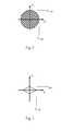
- Fig. 1shows a friction circle, showing the maximum possible acceleration of a vehicle due to available friction in x direction and in y direction.
- the shape as a circleis an idealised situation where it is assumed that exactly the same maximum acceleration might be in any direction, longitudinal, lateral or any combination thereof. In reality, the relationship between longitudinal and lateral directions is likely to be more complicated.
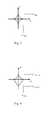
- Fig. 2shows an acceleration limit map with one example of lateral (a y ) and longitudinal (a x ) accelerations relationship for a Curve Speed Estimator (CSE) system according to an exemplary embodiment of the invention.
- a CSEcalculates at least one speed profile for each path.
- the default speed profileis usually a comfort speed profile.
- Other speed profilesmay be a safety speed profile, an eco-driving speed profile or a sporty speed profile, as set by the driver.
- Information about the current static and dynamic environment around and ahead of the current vehicle position together with map datais used to calculate the speed profiles.
- Limitations in the desired speed profileare set by lateral and longitudinal dynamic acceleration limit maps.
- the accelerations in longitudinal and lateral directionsdepend on each other and limitations in the speed are set by the lateral and longitudinal accelerations.
- the accelerationsdepend on each other as mentioned above.
- v iis the vehicle speed in sample point i
- v i +1is the vehicle speed in the next sample point i+1
- C iis the curvature in sample point i of a curve defined as the inverse of the curve radius
- ⁇ T iis the time between two samples.
- the relation between lateral and longitudinal accelerationsmay change due to e.g. road friction, driving style or vehicle state.
- Some vehicle configuration and typemay e.g. allow higher acceleration while driving in a curve.
- the relationmay even depend on taking left-or right turn.
- the aimis to have zero longitudinal acceleration in the points with smallest radius.
- the acceleration limitsare symmetric in the x and y directions respectively.
- the limitations on the lateral and longitudinal accelerationshowever also depend on the vehicle speed, since drivers tend to avoid lateral acceleration more at higher speeds.
- Fig.3shows a further example of an acceleration limit map with lateral (a y ) and longitudinal (a x ) accelerations relationship in accordance with the present invention.
- the x and y acceleration limitsdo not depend linearly on each other.
- a non-linear relationshipis more likely to be more accurate, since available grip depends non-linearly on the longitudinal and lateral accelerations.
- lateral acceleration limitsmay be set at a different value than longitudinal acceleration limits.
- the more aggressive driving stylethe larger the area inside the acceleration limit map will become.
- a comfort or eco driving style acceleration limit mapwill result in a smaller area inside the acceleration limit map and end up well inside the friction circle, thus ensuring available grip.
- Fig.4shows yet another example of an acceleration limit map in accordance with the present invention.
- the allowed lateral accelerations while acceleratingdo not depend on the longitudinal acceleration in the same way as when decelerating.
- Fig.5shows an example of an acceleration limit map, together with the maximum available friction shown as the friction circle. As seen from the figure, the acceleration limit map is well positioned inside the friction circle.
- Fig.6shows an example of what would happen if both the lateral and longitudinal accelerations end limits were reached simultaneously; the resulting acceleration would end up outside of the friction circle.
- the accelerationwill be too high in relation to the available friction and a vehicle in such situation will lose grip with possible road departure as a result thereof. Therefore, it is important to take the relationship between the lateral and longitudinal acceleration into account when deciding the acceleration limits.
- Fig.7shows a principle of a Curve Speed Warning (CSW) system using a Curve Speed Estimation (CSE) system.
- the CSW systemestimates a projected coming speed through an upcoming curve. As shown in the figure, the estimated speed of the vehicle will at the start of a warning zone exceed the suitable speed profile if the speed is not slowed down. The CSW system will then warn the driver accordingly. Warning message and/or warning sound will continue as long as the estimated vehicle speed exceeds the suitable speed profile. Note that the warning zone preferably starts prior to the event that the projected speed exceeds the estimated speed profile, in order to provide the driver time to react and lower the vehicle speed before a potentially hazardous situation occurs.
- Fig.8shows a vehicle approaching a curve with too high speed. Between the start of the warning zone and the end of the warning zone, the projected speed exceeds the suitable speed profile and the Curve Speed Warning system will warn accordingly. Warning will continue until the estimated speed is below the suitable speed profile.
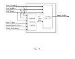
- Fig.9is a block diagram showing an example of a Curve Speed Warning (CSW)/Curve Speed Control (CSC) system architecture.
- the Curve Speed Estimator (CSE)may use information from an Electronic Horizon (EH) using map data, data concerning road friction available, vehicle specific data and parameters set by the driver for estimating a desired speed profile. Dynamic information used to estimate the speed profile may thus be road friction, weather situation, but not current vehicle speed. Static information like type of lane markings and signs along the road are also taken into account from map data. Current vehicle state parameters such as vehicle type, centre of mass affecting roll behavior, number of passengers affecting the load ratio and the weight of the vehicle also affects the speed profile.
- EHElectronic Horizon
- Dynamic information used to estimate the speed profilemay thus be road friction, weather situation, but not current vehicle speed.
- Static informationlike type of lane markings and signs along the road are also taken into account from map data.
- Current vehicle state parameterssuch as vehicle type, centre of mass affecting roll behavior, number of passengers
- the methodmay also take into consideration if a trailer is connected and the mass relation trailer/vehicle.
- the driving style with respect to curve handlingmay further be measured and taken into consideration. Such measures may for example be braking before curves, acceleration at curve exits and cutting corners.
- the Curve Speed Warning (CSW) system and the Curve Speed Control (CSC) systemscompare the estimated speed profile with a predicted coming vehicle speed based on current vehicle speed and current vehicle acceleration to warn the driver and control vehicle speed, respectively.
- Fig.10shows a boundary diagram for an example of a Curve Speed Estimation (CSE) system. From map data, information about road curvature, road banking and road slope is achieved. Further, information about available road friction, vehicle specific data and driver preferences is achieved. Based on this information, estimation of a speed profile is performed.
- CSECurve Speed Estimation
- Fig. 11shows a boundary diagram for an example of a Curve Speed Estimation (CSE) system in accordance with the present invention.
- CSECurve Speed Estimation
- Parameters used to determine the available road frictionmay for example be information regarding the material of the road surface, outside temperature, air moisture content, information from the Anti-Lock Brake System (ABS), Electronic Stability Control (ESC) system and size of any vibrations from the wheels, provided by sensors in the vehicle. Further parameters are road surface finish that may depend on snow, ice, oil or gravel being present on the road surface. Yet further information regarding road friction could be collected via wireless communication with other vehicles and or the traffic infrastructure.
- ABSAnti-Lock Brake System
- ESCElectronic Stability Control
Landscapes
- Engineering & Computer Science (AREA)
- Automation & Control Theory (AREA)
- Transportation (AREA)
- Mechanical Engineering (AREA)
- Human Computer Interaction (AREA)
- Control Of Driving Devices And Active Controlling Of Vehicle (AREA)
- Traffic Control Systems (AREA)
- Navigation (AREA)
- Regulating Braking Force (AREA)
Description
- The present invention relates to a method for estimating a speed profile. The vehicle has a steering wheel and comprises a map database with at least one record. The record presents at least one path, the vehicle being located on the path, and the path presenting a plurality of position points. A portion of the points present adjacent points defining a path section. The vehicle further comprises a locator device communicatively coupled to the map database. The method comprises the steps of determining of the location of the vehicle and matching the location with a first of the points on the path, identifying an approaching path section point and estimating a path section speed profile based in part on map data.
- Run-off accidents that occur due to loss of vehicle control of vehicles, for examples in curves, intersections, roundabouts or the like make up a major part of all run-off-road accidents. According to the Fatal Analysis Reporting System (FARS), a US database saving facts from accidents, 14% of all fatal crashes occurs due to that the vehicle failed to negotiate a curve. To help drivers lower the speed before critical road passages like curves, Curve Speed Warning (CSW) systems have been developed. Such systems alert the driver with audible/visible/haptic etc. warnings to make the driver aware of that the vehicle speed is too high for a safe negotiation of the upcoming curve. Such systems may for example compare the speed of the vehicle with a predetermined maximum limit when a vehicle approaches a critical static traffic environment requiring low speed to be managed safety. If the speed is above the limit, the system warns the driver. A more sophisticated way of checking if the speed is too high to manage an upcoming curve or the like is to estimate a coming speed profile by using the acceleration of the car as well as the current speed. A maximum acceleration limit may then be set at a predetermined distance from an upcoming curve or the like. A step further is so called Curve Speed Control (CSC) systems which autonomously lower the speed of a vehicle before a curve or any other static traffic environment requiring lower speed.
US 2007/0150157A1 , on which the preambles ofclaims 1 and 10 are based, relates to a vehicle curve speed control system adapted for use with a vehicle having a driver. The system includes a map database representing a current vehicle path and a locator device communicatively coupled to the database and configured to determine the location of the vehicle on the path. The system further includes a controller configured to identify approaching curve points of a curve in terms of curvature or radius, and determine a desired speed profile based on driver preference and/or vehicle characteristic input. An acceleration profile is determined, based on the current vehicle speed, and desired speed profile. An acceleration or deceleration command at the present control loop is modified towards achieving an optimal curve speed and is delivered to either a brake or an acceleration module to automatically accelerate or decelerate the vehicle accordingly.- When driving a vehicle on a road, a natural limit for acceleration, or deceleration, is set by the friction available on the road surface. Systems as described above often take into account a maximum possible acceleration in either longitudinal direction or in lateral direction but fails to take a combination thereof into account. If, for example, a driver brakes at the same time as steering through a narrow curve, the maximum lateral acceleration limit may not be reached, but due to the braking operation the vehicle might still lose grip and drive off the road.
- The aim of the present invention is to provide an improved method for estimating a vehicle speed profile.
- A method and a system for estimating a speed profile for a vehicle is provided. Further, a motor vehicle provided with such a system is provided. The vehicle has a steering wheel and comprises a map database with at least one record. The record presents at least one path, the vehicle being located on the path, and the path presenting a plurality of position points. A portion of the points present adjacent points defining a path section. The vehicle further comprises a locator device communicatively coupled to the map database. The method comprises the steps of exterminating of the location of the vehicle and matching the location with a first of the points on the path, identifying an approaching path section point and estimating a path section speed profile based on map data. In the step of estimating the speed profile, an acceleration limit map depending on a relationship between maximum possible longitudinal and maximum possible lateral acceleration is used to determine maximum allowed acceleration in the speed profile.
- The present method is more efficient, safe and accurate than previous known methods due to that, in the step of estimating the speed profile, an acceleration limit map depending on a relationship between maximum possible longitudinal and maximum possible lateral acceleration is calculated to determine maximum allowed acceleration in the speed profile. By taking the relationship between the accelerations into account when calculating the acceleration limit map, the estimated speed profile will be more optimised as well as safer since the acceleration limit map and thus the estimated speed profile reflects true situations more accurately than earlier presented solutions.
- As a result, the above mentioned object is achieved.
- In another embodiment, in the step of estimating the speed profile, calculation of the acceleration limit map is based on at least one parameter set by the driver defining a driving style. Such driving style may for example be comfort driving, eco driving or sporty driving style. An advantage with an estimated speed profile based on the driver's preferences is that the driver will experience a speed profile suggested by the vehicle being in line with the desires of the driver. Irritation of a driver is a risk per se in traffic situations and a content driver is therefore safer.
- In another embodiment, in the step of estimating a speed profile, calculation of the acceleration limit map is based on at least one of the following parameters: parameters relating to available road friction, parameters relating to vehicle specific data. Examples of parameters relating to available road friction might be outside temperature, air moisture content, road surface reflection and road surface type and finish. Modern vehicles are provided with a number of sensors, cameras and the like and a lot of information is available. Taking parameters affecting the available friction into account will lead to a more safe determining of the friction available. Vehicle specific parameters might be vehicle type, current load ratio and current centre of gravity.
- In another embodiment, in the step of estimating the speed profile, determining of the acceleration limit map is based on at least one of the following parameters: road curvature, road banking and road slope.
- In another embodiment, in the step of estimating a speed profile, at least one of the following parameters relating to available friction is used: parameters received from an Anti-Lock Brake ABS system provided in the vehicle, parameters received from an Electronic Stability Control ESC system provided in the vehicle, outside temperature, air moisture content, road surface reflection, road surface finish, parameters wirelessly received from other vehicles and parameters wirelessly received from the surrounding infrastructure. The surrounding infrastructure may for example be a mobile phone network, a radio message or a message sent from a traffic sign or the like.
- In another embodiment, the method comprises the further step of calculating a projected path section vehicle speed profile based on current vehicle speed, current vehicle longitudinal acceleration and current vehicle lateral acceleration,
and comparing the estimated path section speed profile with the projected path section speed profile. - In another embodiment, the method further comprises the step of warning the driver if the projected path section vehicle speed profile exceeds the estimated path section speed profile. In this case, the warning is preferably issued prior to the event that the projected path section speed exceeds the estimated path section speed profile, in order to provide the driver time to react and lower the vehicle speed before a potentially hazardous situation occurs.
- In another embodiment, the method further comprises the step of decelerating the vehicle if the projected path section vehicle speed profile exceeds the estimated path section speed profile.
- In another embodiment, the method further comprises the step of informing the driver if the projected path section vehicle speed profile is below the estimated path section speed profile.
- Further features of, and advantages with, the present invention will become apparent when studying the appended claims and the following detailed description. Those skilled in the art will realize that different features of the present invention may be combined to create embodiments other than those described in the following, without departing from the scope of the present invention, as defined by the appended claims.
- The various aspects of the invention, including its particular features and advantages, will be readily understood from the following detailed description and the accompanying drawings, in which:
Fig. 1 illustrates a friction circle. The circle represents maximum acceleration due to available friction in x and y direction.Fig. 2 shows one example of lateral (ay) and longitudinal (ax) accelerations relationship for a Curve Speed Estimator (CSE) system.Fig.3 shows a further example of lateral (ay) and longitudinal (ax) accelerations relationship.Fig.4 shows an example of a general lateral (ay) and longitudinal (ax) accelerations relationship.Fig.5 shows an example of a general lateral (ay) and longitudinal (ax) accelerations relationship, together with the maximum available friction shown as a friction circle. In the figure, the accelerations ay and ax have been normalized with the gravitational constantg.Fig.6 shows that the acceleration will end up outside the friction circle, with lose of grip as a result, if both the lateral (ay) and longitudinal (ax) accelerations limits are reached simultaneously without taken into account the relationship between them. In the figure, the accelerations ay and ax have been normalized with the gravitational constant g.Fig.7 shows a principle of Curve Speed Warning (CSW) system using a Curve Speed Estimation (CSE) system.Fig.8 shows a vehicle approaching a curve with too high speed.Fig.9 is a block diagram showing one example of a Curve Speed Warning (CSW)/Curve Speed Control (CSC) system architecture.Fig.10 shows boundary diagram for a Curve Speed Estimation (CSE) system.Fig. 11 shows an acceleration limit map in accordance with the present invention.- The present invention will now be described more fully with reference to the accompanying drawings, in which example embodiments are shown. However, this invention should not be construed as limited to the embodiments set forth herein. Disclosed features of example embodiments may be combined as readily understood by one of ordinary skill in the art to which this invention belongs. Like numbers refer to like elements throughout.
- Well-known functions or constructions will not necessarily be described in detail for brevity and/or clarity.
Fig. 1 shows a friction circle, showing the maximum possible acceleration of a vehicle due to available friction in x direction and in y direction. The shape as a circle is an idealised situation where it is assumed that exactly the same maximum acceleration might be in any direction, longitudinal, lateral or any combination thereof. In reality, the relationship between longitudinal and lateral directions is likely to be more complicated.- Maximum available friction is given by available road friction p, and the gravitational constant g, as µ*g. A lot of parameters affect the friction available, such as outside temperature, road surface material and air moisture content, road surface structure, road surface. As may be seen from the figure, friction available may be used for acceleration, or deceleration, in longitudinal direction, in lateral direction or a combination thereof. If the acceleration in any direction exceeds the circle, the vehicle will lose grip risking a run-off accident as a consequence.
Fig. 2 shows an acceleration limit map with one example of lateral (ay) and longitudinal (ax) accelerations relationship for a Curve Speed Estimator (CSE) system according to an exemplary embodiment of the invention. A CSE calculates at least one speed profile for each path. The default speed profile is usually a comfort speed profile. Other speed profiles may be a safety speed profile, an eco-driving speed profile or a sporty speed profile, as set by the driver. Information about the current static and dynamic environment around and ahead of the current vehicle position together with map data is used to calculate the speed profiles. Limitations in the desired speed profile are set by lateral and longitudinal dynamic acceleration limit maps.- The accelerations in longitudinal and lateral directions depend on each other and limitations in the speed are set by the lateral and longitudinal accelerations. The accelerations depend on each other as mentioned above. The relation between the speed and the two accelerations may be expressed as


Fig.3 shows a further example of an acceleration limit map with lateral (ay) and longitudinal (ax) accelerations relationship in accordance with the present invention. In this example, the x and y acceleration limits do not depend linearly on each other. A non-linear relationship is more likely to be more accurate, since available grip depends non-linearly on the longitudinal and lateral accelerations. Further, due to both comfort and safety reasons, lateral acceleration limits may be set at a different value than longitudinal acceleration limits. The more aggressive driving style, the larger the area inside the acceleration limit map will become. A comfort or eco driving style acceleration limit map will result in a smaller area inside the acceleration limit map and end up well inside the friction circle, thus ensuring available grip.Fig.4 shows yet another example of an acceleration limit map in accordance with the present invention. In this example, the allowed lateral accelerations while accelerating do not depend on the longitudinal acceleration in the same way as when decelerating.Fig.5 shows an example of an acceleration limit map, together with the maximum available friction shown as the friction circle. As seen from the figure, the acceleration limit map is well positioned inside the friction circle.Fig.6 shows an example of what would happen if both the lateral and longitudinal accelerations end limits were reached simultaneously; the resulting acceleration would end up outside of the friction circle. Thus, the acceleration will be too high in relation to the available friction and a vehicle in such situation will lose grip with possible road departure as a result thereof. Therefore, it is important to take the relationship between the lateral and longitudinal acceleration into account when deciding the acceleration limits.Fig.7 shows a principle of a Curve Speed Warning (CSW) system using a Curve Speed Estimation (CSE) system. The CSW system estimates a projected coming speed through an upcoming curve. As shown in the figure, the estimated speed of the vehicle will at the start of a warning zone exceed the suitable speed profile if the speed is not slowed down. The CSW system will then warn the driver accordingly. Warning message and/or warning sound will continue as long as the estimated vehicle speed exceeds the suitable speed profile. Note that the warning zone preferably starts prior to the event that the projected speed exceeds the estimated speed profile, in order to provide the driver time to react and lower the vehicle speed before a potentially hazardous situation occurs.Fig.8 shows a vehicle approaching a curve with too high speed. Between the start of the warning zone and the end of the warning zone, the projected speed exceeds the suitable speed profile and the Curve Speed Warning system will warn accordingly. Warning will continue until the estimated speed is below the suitable speed profile.Fig.9 is a block diagram showing an example of a Curve Speed Warning (CSW)/Curve Speed Control (CSC) system architecture. The Curve Speed Estimator (CSE) may use information from an Electronic Horizon (EH) using map data, data concerning road friction available, vehicle specific data and parameters set by the driver for estimating a desired speed profile. Dynamic information used to estimate the speed profile may thus be road friction, weather situation, but not current vehicle speed. Static information like type of lane markings and signs along the road are also taken into account from map data. Current vehicle state parameters such as vehicle type, centre of mass affecting roll behavior, number of passengers affecting the load ratio and the weight of the vehicle also affects the speed profile. The method may also take into consideration if a trailer is connected and the mass relation trailer/vehicle. The driving style with respect to curve handling may further be measured and taken into consideration. Such measures may for example be braking before curves, acceleration at curve exits and cutting corners. The Curve Speed Warning (CSW) system and the Curve Speed Control (CSC) systems compare the estimated speed profile with a predicted coming vehicle speed based on current vehicle speed and current vehicle acceleration to warn the driver and control vehicle speed, respectively.Fig.10 shows a boundary diagram for an example of a Curve Speed Estimation (CSE) system. From map data, information about road curvature, road banking and road slope is achieved. Further, information about available road friction, vehicle specific data and driver preferences is achieved. Based on this information, estimation of a speed profile is performed.Fig. 11 shows a boundary diagram for an example of a Curve Speed Estimation (CSE) system in accordance with the present invention. To determine a dynamic acceleration limit map, data relating to available road friction, the specific vehicle driven and preferences set by the driver are taken into account. The acceleration limit map is based on a relationship present between the acceleration in lateral and longitudinal directions as shown inFigs. 2-5 . The map is re-calculated continuously depending on changes in data affecting the acceleration limits.- Parameters used to determine the available road friction may for example be information regarding the material of the road surface, outside temperature, air moisture content, information from the Anti-Lock Brake System (ABS), Electronic Stability Control (ESC) system and size of any vibrations from the wheels, provided by sensors in the vehicle. Further parameters are road surface finish that may depend on snow, ice, oil or gravel being present on the road surface. Yet further information regarding road friction could be collected via wireless communication with other vehicles and or the traffic infrastructure.
- From the vehicle, information about centre of gravity, current load ratio, current speed and current acceleration in longitudinal direction as well as in lateral direction may be used. Although the invention has been described with reference to example embodiments, many different alterations, modifications and the like will become apparent for those skilled in the art within the scope of the appended claims.
- Unless otherwise defined, all terms (including technical and scientific terms) used herein have the same meaning as commonly understood by one of ordinary skill in the art to which this invention belongs. It will be further understood that terms, such as those defined in commonly used dictionaries, should be interpreted as having a meaning that is consistent with their meaning in the context of the relevant art and will not be interpreted in an idealized or overly formal sense unless expressly so defined herein.


Claims (11)
- Method for estimating a speed profile for a vehicle, the vehicle having a steering wheel and comprising a map database with at least one record, wherein the record presents at least one path, the vehicle being located on the path, the path presenting a plurality of position points, and wherein a portion of the points present adjacent points defining a path section, the vehicle further comprising a locator device communicatively coupled to the map database,
the method comprising the steps of:- determining of the location of the vehicle and matching the location with a first of the points on the path,- identifying an approaching path section point,- estimating a speed profile based on map data,
characterized in that
in the step of estimating the speed profile, an acceleration limit map depending on a relationship between a maximum possible longitudinal acceleration and a maximum possible lateral acceleration is used to determine the maximum allowed accelerations in the speed profile. - Method according to claim 1, wherein in the step of estimating the speed profile, determining of the acceleration limit map is based on at least one parameter set by the driver defining a driving style.
- Method according to claim 1 or 2, wherein, in the step of estimating the speed profile, determining of the acceleration limit map is based on at least one of the following parameters: parameters relating to available road friction and parameters relating to vehicle specific data.
- Method according to claim 1, 2 or 3 wherein, in the step of estimating the speed profile, determining of the acceleration limit map is based on at least one of the following parameters: road curvature, road banking and road slope.
- Method according to claim 3, wherein, in the step of estimating the speed profile, at least one of the following parameters relating to available friction is used: parameters received from an Anti-Lock Brake ABS system provided in the vehicle, parameters received from an Electronic Stability Control ESC system provided in the vehicle, outside temperature, air moisture content, road surface reflection, road surface finish, parameters wirelessly received from other vehicles and parameters wirelessly received from an surrounding infrastructure.
- Method according to any preceding claim, comprising the further step of- calculating a projected path section vehicle speed profile based on current vehicle speed, current vehicle longitudinal acceleration and current vehicle lateral acceleration,- comparing the estimated path section speed profile with the projected path section speed profile.
- Method according to the claim 6, comprising the further step of- warning the driver if the projected path section speed profile exceeds the estimated path section speed profile.
- Method according to claim 6 or 7, comprising the further step of decelerating the vehicle if the projected path section speed profile exceeds the estimated path section speed profile.
- Method according to any of claim 6-8, comprising the further step of informing the driver if the projected path section speed profile is below the estimated path section speed profile.
- System for estimating a speed profile for a vehicle, the vehicle having a steering wheel and comprising a map database with at least one record, wherein the record presents at least one path, the vehicle being located on the path, the path presenting a plurality of position points, and wherein a portion of the points present adjacent points defining a path section, the vehicle further comprising a locator device communicatively coupled to the map database,
the system comprising- means for determining of the location of the vehicle and matching the location with a first of the points on the path,- means for identifying an approaching path section point,- means for estimating a speed profile based on map data,
characterized in that
the means for estimating the speed profile comprises an acceleration limit map depending on a relationship between a maximum possible longitudinal acceleration and a maximum possible lateral acceleration is used to determine the maximum allowed accelerations in the speed profile. - A motor vehicle provided with a system in accordance with claim 10.
Priority Applications (3)
| Application Number | Priority Date | Filing Date | Title |
|---|---|---|---|
| EP11170874.9AEP2537727B1 (en) | 2011-06-22 | 2011-06-22 | Method for estimating a speed profile for a vehicle |
| US13/527,165US9187097B2 (en) | 2011-06-22 | 2012-06-19 | Method and apparatus for speed estimation and control |
| CN201210214069.5ACN102837703B (en) | 2011-06-22 | 2012-06-25 | Estimate the method and system of vehicle speed curve and include the motor vehicles of this system |
Applications Claiming Priority (1)
| Application Number | Priority Date | Filing Date | Title |
|---|---|---|---|
| EP11170874.9AEP2537727B1 (en) | 2011-06-22 | 2011-06-22 | Method for estimating a speed profile for a vehicle |
Publications (2)
| Publication Number | Publication Date |
|---|---|
| EP2537727A1 EP2537727A1 (en) | 2012-12-26 |
| EP2537727B1true EP2537727B1 (en) | 2015-03-11 |
Family
ID=44512581
Family Applications (1)
| Application Number | Title | Priority Date | Filing Date |
|---|---|---|---|
| EP11170874.9AActiveEP2537727B1 (en) | 2011-06-22 | 2011-06-22 | Method for estimating a speed profile for a vehicle |
Country Status (3)
| Country | Link |
|---|---|
| US (1) | US9187097B2 (en) |
| EP (1) | EP2537727B1 (en) |
| CN (1) | CN102837703B (en) |
Families Citing this family (44)
| Publication number | Priority date | Publication date | Assignee | Title |
|---|---|---|---|---|
| EP2885186B1 (en)* | 2012-08-16 | 2019-05-01 | Jaguar Land Rover Limited | System and method for controlling vehcile speed to enhance occupant comfort |
| DE102013200724A1 (en)* | 2013-01-18 | 2014-07-24 | Bayerische Motoren Werke Aktiengesellschaft | Predicting a driving maneuver of a vehicle |
| US20140244076A1 (en)* | 2013-02-28 | 2014-08-28 | Honeywell International, Inc., Patent Services M/S Ab/2B | Stability based taxiing and turning method for aircraft with electric taxi system |
| US9081651B2 (en)* | 2013-03-13 | 2015-07-14 | Ford Global Technologies, Llc | Route navigation with optimal speed profile |
| GB201315617D0 (en)* | 2013-09-03 | 2013-10-16 | Jaguar Land Rover Ltd | Cruise control system for a vehicle |
| US9944297B2 (en) | 2014-01-10 | 2018-04-17 | E-Novia S.R.L. | System and method for estimating the driving style of a vehicle |
| JP6349942B2 (en)* | 2014-05-12 | 2018-07-04 | 株式会社デンソー | Driving assistance device |
| BR112016024907B1 (en)* | 2014-05-21 | 2022-09-20 | Scania Cv Ab | METHOD FOR ADAPTATION OF THE DIRECTION OF A VEHICLE ON A ROAD IN ASSOCIATION WITH MAKING A TURN, SYSTEM FOR ADAPTATION OF THE DIRECTION OF A VEHICLE ON A ROAD IN ASSOCIATION WITH MAKING A TURN, AND, VEHICLE |
| US10246094B2 (en) | 2014-12-09 | 2019-04-02 | Ford Global Technologies, Llc | Autonomous vehicle cornering maneuver |
| FR3029878B1 (en)* | 2014-12-16 | 2017-01-13 | Michelin & Cie | METHOD FOR PREDICTING THE SPEED OF A DRIVER AT THE STEERING WHEEL OF A VEHICLE |
| CN112902975B (en)* | 2015-02-10 | 2024-04-30 | 御眼视觉技术有限公司 | Autonomous vehicle navigation method, readable device, server, vehicle and system |
| FR3034066B1 (en)* | 2015-03-26 | 2017-03-24 | Peugeot Citroen Automobiles Sa | DEVICE FOR REGULATING THE SPEED OF A VEHICLE BY INSTALLING A DECELERATION PROFILE ADAPTED TO A NEXT LIMITATION OF SPEED |
| FR3036354A1 (en)* | 2015-05-20 | 2016-11-25 | Michelin & Cie | METHOD FOR DETERMINING A RUNNING LIMIT SPEED |
| KR20170046340A (en)* | 2015-10-21 | 2017-05-02 | 현대자동차주식회사 | Advanced driver assist system and vehicle comprising the same, control method for the advanced driver assist system |
| CN107092920A (en)* | 2016-02-17 | 2017-08-25 | 福特全球技术公司 | Assessing traveling thereon has the method and apparatus on road surface of vehicle |
| FR3051423B1 (en)* | 2016-05-20 | 2018-05-25 | Compagnie Generale Des Etablissements Michelin | METHOD FOR PROPOSING A RUNNING SPEED |
| US11312383B2 (en)* | 2016-09-13 | 2022-04-26 | Panasonic Intellectual Property Management Co., Ltd. | Road surface condition prediction system, driving assistance system, road surface condition prediction method, and data distribution method |
| CN106564506B (en)* | 2016-11-08 | 2019-01-18 | 上海海积信息科技股份有限公司 | Whether a kind of prediction vehicle position information closes the method and device of rule |
| CN109476310B (en)* | 2016-12-30 | 2021-11-12 | 同济大学 | Automatic driving vehicle speed control method based on comfort level |
| CN106740868B (en)* | 2016-12-30 | 2019-03-29 | 东软集团股份有限公司 | A kind of method, apparatus and equipment of speed planning |
| CN106773714B (en)* | 2017-01-19 | 2019-08-06 | 北京理工大学 | A control method for in-wheel motor-driven vehicles based on a self-tuning particle model |
| CN106926845B (en)* | 2017-03-02 | 2019-02-12 | 中国第一汽车股份有限公司 | A Dynamic Estimation Method of Vehicle State Parameters |
| US11498570B2 (en)* | 2017-03-24 | 2022-11-15 | Compagnie Generale Des Etablissements Michelin | Method and system for real-time estimation of road conditions and vehicle behavior |
| EP3556629B1 (en) | 2018-04-19 | 2025-08-13 | Volvo Car Corporation | Method and system for vehicle curve speed restriction |
| CN109353342B (en)* | 2018-11-14 | 2023-09-26 | 南京航空航天大学 | A vehicle curve safety speed control system and method |
| IT201800010456A1 (en)* | 2018-11-20 | 2020-05-20 | Fiat Ricerche | ELECTRONIC PREVENTIVE CHECK OF THE DRIVING STABILITY OF A MOTOR VEHICLE |
| US11142209B2 (en)* | 2019-02-12 | 2021-10-12 | Ford Global Technologies, Llc | Vehicle road friction control |
| CN109910905B (en)* | 2019-03-01 | 2020-07-28 | 同济大学 | Multi-condition speed estimation method for distributed driving vehicles based on slope estimation correction |
| GB2611225B (en)* | 2019-05-29 | 2023-10-18 | Motional Ad Llc | Estimating speed profiles |
| US11814046B2 (en) | 2019-05-29 | 2023-11-14 | Motional Ad Llc | Estimating speed profiles |
| US11548520B2 (en)* | 2019-10-11 | 2023-01-10 | Mitsubishi Electric Research Laboratories, Inc. | Control of autonomous vehicles adaptive to user driving preferences |
| CN110861637B (en)* | 2019-11-29 | 2021-02-12 | 辽宁工业大学 | Automobile electronic steering safety early warning system and early warning method |
| CN113548036B (en)* | 2020-04-17 | 2023-12-01 | 广州汽车集团股份有限公司 | Engine output torque adjusting method, system and control equipment thereof |
| FR3115256A1 (en)* | 2020-10-16 | 2022-04-22 | IFP Energies Nouvelles | METHOD FOR DETERMINING A SPEED PROFILE MINIMIZING THE POLLUTING EMISSIONS OF A VEHICLE |
| CN112677982B (en)* | 2020-12-25 | 2022-06-14 | 重庆大学 | Vehicle Longitudinal Velocity Planning Method Based on Driver Characteristics |
| US20210316758A1 (en)* | 2021-06-24 | 2021-10-14 | Intel Corporation | Proactive vehicle safety system |
| US20220410876A1 (en)* | 2021-06-28 | 2022-12-29 | Volvo Car Corporation | Road condition adaptive dynamic curve speed control |
| CN116198516A (en)* | 2021-12-01 | 2023-06-02 | 北京罗克维尔斯科技有限公司 | Vehicle speed splicing method and device, electronic equipment and storage medium |
| BE1029667B1 (en)* | 2021-12-02 | 2023-03-02 | Ivex | METHODS, SYSTEMS, STORAGE MEDIA AND EQUIPMENT FOR ANALYZING THE BAND ROAD FRICTION ESTIMATE OF TRAVEL CANDIDATES AT THE PLANNER LEVEL FOR SAFER ROUTE SELECTION IN AUTOMATED VEHICLES |
| IT202200007013A1 (en)* | 2022-04-08 | 2023-10-08 | Ferrari Spa | CONTROL METHOD FOR AN ELECTRIC ROAD VEHICLE DRIVEN BY A DRIVER AND THEIR ROAD VEHICLE |
| DE102022109157A1 (en)* | 2022-04-13 | 2023-10-19 | Bayerische Motoren Werke Aktiengesellschaft | Method for supporting a driver of a vehicle when driving along a predetermined route, computer-readable (storage) medium, assistance system for a vehicle |
| US12291207B2 (en) | 2022-09-07 | 2025-05-06 | Ford Global Technologies, Llc | Driver assistance for high accelleration and speed on a minimum time path |
| US12325409B2 (en)* | 2022-12-22 | 2025-06-10 | Nissan North America, Inc. | Map-based braking |
| KR20250136330A (en)* | 2023-01-23 | 2025-09-16 | 스티브 랜더 | Speed monitoring |
Family Cites Families (8)
| Publication number | Priority date | Publication date | Assignee | Title |
|---|---|---|---|---|
| JPS6348181A (en)* | 1986-04-11 | 1988-02-29 | Nippon Electric Ind Co Ltd | Movement controller for induction motor |
| DE10242124B4 (en)* | 2002-09-11 | 2009-12-10 | Robert Bosch Gmbh | Method and device for adjusting the engine torque of a single-track motor vehicle |
| EP1648736A4 (en)* | 2003-06-04 | 2010-06-02 | Daimler Ag | Curve rollover warning system for trucks |
| US7400963B2 (en)* | 2005-12-09 | 2008-07-15 | Gm Global Technology Operations, Inc. | Speed control method for vehicle approaching and traveling on a curve |
| US7774121B2 (en)* | 2007-07-31 | 2010-08-10 | Gm Global Technology Operations, Inc. | Curve speed control system with adaptive map preview time and driving mode selection |
| JP4724163B2 (en)* | 2007-09-14 | 2011-07-13 | 株式会社豊田中央研究所 | Body speed estimation device |
| US8686845B2 (en)* | 2010-02-25 | 2014-04-01 | Ford Global Technologies, Llc | Automotive vehicle and method for advising a driver therein |
| US8478499B2 (en)* | 2010-06-07 | 2013-07-02 | Ford Global Technologies, Llc | System and method for vehicle speed monitoring using historical speed data |
- 2011
- 2011-06-22EPEP11170874.9Apatent/EP2537727B1/enactiveActive
- 2012
- 2012-06-19USUS13/527,165patent/US9187097B2/enactiveActive
- 2012-06-25CNCN201210214069.5Apatent/CN102837703B/enactiveActive
Also Published As
| Publication number | Publication date |
|---|---|
| EP2537727A1 (en) | 2012-12-26 |
| US9187097B2 (en) | 2015-11-17 |
| CN102837703A (en) | 2012-12-26 |
| CN102837703B (en) | 2016-12-21 |
| US20120326856A1 (en) | 2012-12-27 |
Similar Documents
| Publication | Publication Date | Title |
|---|---|---|
| EP2537727B1 (en) | Method for estimating a speed profile for a vehicle | |
| CN115214661B (en) | Cooperative adaptive cruise control system based on target vehicle's driving style | |
| CN107415945B (en) | Automatic driving system for evaluating lane change and using method thereof | |
| US12017648B2 (en) | Vehicle control device | |
| EP2956343B1 (en) | Simultaneous estimation of at least mass and rolling resistance | |
| CN102632888B (en) | A method and a warning device for warning a vehicle driver, and a vehicle | |
| CN103348395B (en) | Traffic congestion detection apparatus and vehicle control apparatus | |
| EP2546817B1 (en) | Safe vehicle driving facilitating system | |
| EP3480074B1 (en) | Method and system for controlling a vehicle tire-to-road friction estimation | |
| CN111247045A (en) | Vehicle control device | |
| US20150185036A1 (en) | Method and device for ascertaining a source of danger on atravel route | |
| CN105539432A (en) | Method and system for mitigating the effects of an impaired driver | |
| CN112092811B (en) | Predicted gradient optimization in cruise control | |
| WO2015178839A1 (en) | Method and system for adapting the acceleration of a vehicle during driving of the vehicle along a route of travel | |
| JP2009537367A (en) | Method and apparatus for avoiding vehicle collisions | |
| JP6326968B2 (en) | Driving support system and driving support method | |
| KR20170007362A (en) | Method and system for improving the operating efficiency of a vehicle during driving of a vehicle along a route of travel | |
| CN108602514A (en) | Operator Skill Score Based on Comparison to Automated Vehicle Operation | |
| EP3871058B1 (en) | A method for controlling a platoon of vehicles | |
| JP2010271844A (en) | Driving support control device and program | |
| KR20120053899A (en) | Automatic setting method for scc velocity based on road traffic data and scc system for vehicle | |
| EP3145778B1 (en) | Method and system for adapting the velocity of a vehicle during driving of the vehicle along a route of travel | |
| CN106414204A (en) | Determining a critical vehicle state and a vehicle minimum distance | |
| WO2013191621A1 (en) | Method and system for velocity adaptation during forward travel of a motor vehicle | |
| KR20170005077A (en) | Method and system for the adaptation of the driving of a vehicle on a roadway in association with taking a curve |
Legal Events
| Date | Code | Title | Description |
|---|---|---|---|
| PUAI | Public reference made under article 153(3) epc to a published international application that has entered the european phase | Free format text:ORIGINAL CODE: 0009012 | |
| AK | Designated contracting states | Kind code of ref document:A1 Designated state(s):AL AT BE BG CH CY CZ DE DK EE ES FI FR GB GR HR HU IE IS IT LI LT LU LV MC MK MT NL NO PL PT RO RS SE SI SK SM TR | |
| AX | Request for extension of the european patent | Extension state:BA ME | |
| 17P | Request for examination filed | Effective date:20130626 | |
| RBV | Designated contracting states (corrected) | Designated state(s):AL AT BE BG CH CY CZ DE DK EE ES FI FR GB GR HR HU IE IS IT LI LT LU LV MC MK MT NL NO PL PT RO RS SE SI SK SM TR | |
| GRAP | Despatch of communication of intention to grant a patent | Free format text:ORIGINAL CODE: EPIDOSNIGR1 | |
| RIC1 | Information provided on ipc code assigned before grant | Ipc:B60W 30/18 20120101ALI20140902BHEP Ipc:B60W 30/14 20060101AFI20140902BHEP Ipc:B60W 50/14 20120101ALI20140902BHEP Ipc:B60W 50/00 20060101ALI20140902BHEP | |
| INTG | Intention to grant announced | Effective date:20141002 | |
| GRAS | Grant fee paid | Free format text:ORIGINAL CODE: EPIDOSNIGR3 | |
| GRAA | (expected) grant | Free format text:ORIGINAL CODE: 0009210 | |
| AK | Designated contracting states | Kind code of ref document:B1 Designated state(s):AL AT BE BG CH CY CZ DE DK EE ES FI FR GB GR HR HU IE IS IT LI LT LU LV MC MK MT NL NO PL PT RO RS SE SI SK SM TR | |
| REG | Reference to a national code | Ref country code:GB Ref legal event code:FG4D | |
| REG | Reference to a national code | Ref country code:CH Ref legal event code:EP | |
| REG | Reference to a national code | Ref country code:IE Ref legal event code:FG4D | |
| REG | Reference to a national code | Ref country code:AT Ref legal event code:REF Ref document number:715135 Country of ref document:AT Kind code of ref document:T Effective date:20150415 | |
| REG | Reference to a national code | Ref country code:DE Ref legal event code:R096 Ref document number:602011014532 Country of ref document:DE Effective date:20150423 | |
| REG | Reference to a national code | Ref country code:SE Ref legal event code:TRGR | |
| REG | Reference to a national code | Ref country code:NL Ref legal event code:VDEP Effective date:20150311 | |
| REG | Reference to a national code | Ref country code:NL Ref legal event code:VDEP Effective date:20150311 | |
| PG25 | Lapsed in a contracting state [announced via postgrant information from national office to epo] | Ref country code:ES Free format text:LAPSE BECAUSE OF FAILURE TO SUBMIT A TRANSLATION OF THE DESCRIPTION OR TO PAY THE FEE WITHIN THE PRESCRIBED TIME-LIMIT Effective date:20150311 Ref country code:FI Free format text:LAPSE BECAUSE OF FAILURE TO SUBMIT A TRANSLATION OF THE DESCRIPTION OR TO PAY THE FEE WITHIN THE PRESCRIBED TIME-LIMIT Effective date:20150311 Ref country code:LT Free format text:LAPSE BECAUSE OF FAILURE TO SUBMIT A TRANSLATION OF THE DESCRIPTION OR TO PAY THE FEE WITHIN THE PRESCRIBED TIME-LIMIT Effective date:20150311 Ref country code:HR Free format text:LAPSE BECAUSE OF FAILURE TO SUBMIT A TRANSLATION OF THE DESCRIPTION OR TO PAY THE FEE WITHIN THE PRESCRIBED TIME-LIMIT Effective date:20150311 Ref country code:NO Free format text:LAPSE BECAUSE OF FAILURE TO SUBMIT A TRANSLATION OF THE DESCRIPTION OR TO PAY THE FEE WITHIN THE PRESCRIBED TIME-LIMIT Effective date:20150611 | |
| REG | Reference to a national code | Ref country code:AT Ref legal event code:MK05 Ref document number:715135 Country of ref document:AT Kind code of ref document:T Effective date:20150311 | |
| REG | Reference to a national code | Ref country code:LT Ref legal event code:MG4D | |
| PG25 | Lapsed in a contracting state [announced via postgrant information from national office to epo] | Ref country code:GR Free format text:LAPSE BECAUSE OF FAILURE TO SUBMIT A TRANSLATION OF THE DESCRIPTION OR TO PAY THE FEE WITHIN THE PRESCRIBED TIME-LIMIT Effective date:20150612 Ref country code:LV Free format text:LAPSE BECAUSE OF FAILURE TO SUBMIT A TRANSLATION OF THE DESCRIPTION OR TO PAY THE FEE WITHIN THE PRESCRIBED TIME-LIMIT Effective date:20150311 Ref country code:RS Free format text:LAPSE BECAUSE OF FAILURE TO SUBMIT A TRANSLATION OF THE DESCRIPTION OR TO PAY THE FEE WITHIN THE PRESCRIBED TIME-LIMIT Effective date:20150311 | |
| PG25 | Lapsed in a contracting state [announced via postgrant information from national office to epo] | Ref country code:NL Free format text:LAPSE BECAUSE OF FAILURE TO SUBMIT A TRANSLATION OF THE DESCRIPTION OR TO PAY THE FEE WITHIN THE PRESCRIBED TIME-LIMIT Effective date:20150311 | |
| PG25 | Lapsed in a contracting state [announced via postgrant information from national office to epo] | Ref country code:PT Free format text:LAPSE BECAUSE OF FAILURE TO SUBMIT A TRANSLATION OF THE DESCRIPTION OR TO PAY THE FEE WITHIN THE PRESCRIBED TIME-LIMIT Effective date:20150713 Ref country code:SK Free format text:LAPSE BECAUSE OF FAILURE TO SUBMIT A TRANSLATION OF THE DESCRIPTION OR TO PAY THE FEE WITHIN THE PRESCRIBED TIME-LIMIT Effective date:20150311 Ref country code:EE Free format text:LAPSE BECAUSE OF FAILURE TO SUBMIT A TRANSLATION OF THE DESCRIPTION OR TO PAY THE FEE WITHIN THE PRESCRIBED TIME-LIMIT Effective date:20150311 Ref country code:CZ Free format text:LAPSE BECAUSE OF FAILURE TO SUBMIT A TRANSLATION OF THE DESCRIPTION OR TO PAY THE FEE WITHIN THE PRESCRIBED TIME-LIMIT Effective date:20150311 Ref country code:RO Free format text:LAPSE BECAUSE OF FAILURE TO SUBMIT A TRANSLATION OF THE DESCRIPTION OR TO PAY THE FEE WITHIN THE PRESCRIBED TIME-LIMIT Effective date:20150311 | |
| PG25 | Lapsed in a contracting state [announced via postgrant information from national office to epo] | Ref country code:AT Free format text:LAPSE BECAUSE OF FAILURE TO SUBMIT A TRANSLATION OF THE DESCRIPTION OR TO PAY THE FEE WITHIN THE PRESCRIBED TIME-LIMIT Effective date:20150311 Ref country code:IS Free format text:LAPSE BECAUSE OF FAILURE TO SUBMIT A TRANSLATION OF THE DESCRIPTION OR TO PAY THE FEE WITHIN THE PRESCRIBED TIME-LIMIT Effective date:20150711 Ref country code:PL Free format text:LAPSE BECAUSE OF FAILURE TO SUBMIT A TRANSLATION OF THE DESCRIPTION OR TO PAY THE FEE WITHIN THE PRESCRIBED TIME-LIMIT Effective date:20150311 | |
| REG | Reference to a national code | Ref country code:DE Ref legal event code:R097 Ref document number:602011014532 Country of ref document:DE | |
| PG25 | Lapsed in a contracting state [announced via postgrant information from national office to epo] | Ref country code:IT Free format text:LAPSE BECAUSE OF FAILURE TO SUBMIT A TRANSLATION OF THE DESCRIPTION OR TO PAY THE FEE WITHIN THE PRESCRIBED TIME-LIMIT Effective date:20150311 | |
| PLBE | No opposition filed within time limit | Free format text:ORIGINAL CODE: 0009261 | |
| STAA | Information on the status of an ep patent application or granted ep patent | Free format text:STATUS: NO OPPOSITION FILED WITHIN TIME LIMIT | |
| PG25 | Lapsed in a contracting state [announced via postgrant information from national office to epo] | Ref country code:MC Free format text:LAPSE BECAUSE OF FAILURE TO SUBMIT A TRANSLATION OF THE DESCRIPTION OR TO PAY THE FEE WITHIN THE PRESCRIBED TIME-LIMIT Effective date:20150311 Ref country code:DK Free format text:LAPSE BECAUSE OF FAILURE TO SUBMIT A TRANSLATION OF THE DESCRIPTION OR TO PAY THE FEE WITHIN THE PRESCRIBED TIME-LIMIT Effective date:20150311 | |
| REG | Reference to a national code | Ref country code:CH Ref legal event code:PL | |
| 26N | No opposition filed | Effective date:20151214 | |
| PG25 | Lapsed in a contracting state [announced via postgrant information from national office to epo] | Ref country code:LU Free format text:LAPSE BECAUSE OF FAILURE TO SUBMIT A TRANSLATION OF THE DESCRIPTION OR TO PAY THE FEE WITHIN THE PRESCRIBED TIME-LIMIT Effective date:20150622 Ref country code:SI Free format text:LAPSE BECAUSE OF FAILURE TO SUBMIT A TRANSLATION OF THE DESCRIPTION OR TO PAY THE FEE WITHIN THE PRESCRIBED TIME-LIMIT Effective date:20150311 | |
| REG | Reference to a national code | Ref country code:IE Ref legal event code:MM4A | |
| REG | Reference to a national code | Ref country code:FR Ref legal event code:ST Effective date:20160229 | |
| PG25 | Lapsed in a contracting state [announced via postgrant information from national office to epo] | Ref country code:LI Free format text:LAPSE BECAUSE OF NON-PAYMENT OF DUE FEES Effective date:20150630 Ref country code:IE Free format text:LAPSE BECAUSE OF NON-PAYMENT OF DUE FEES Effective date:20150622 Ref country code:CH Free format text:LAPSE BECAUSE OF NON-PAYMENT OF DUE FEES Effective date:20150630 | |
| PG25 | Lapsed in a contracting state [announced via postgrant information from national office to epo] | Ref country code:FR Free format text:LAPSE BECAUSE OF NON-PAYMENT OF DUE FEES Effective date:20150630 | |
| PG25 | Lapsed in a contracting state [announced via postgrant information from national office to epo] | Ref country code:BE Free format text:LAPSE BECAUSE OF FAILURE TO SUBMIT A TRANSLATION OF THE DESCRIPTION OR TO PAY THE FEE WITHIN THE PRESCRIBED TIME-LIMIT Effective date:20150311 | |
| PG25 | Lapsed in a contracting state [announced via postgrant information from national office to epo] | Ref country code:MT Free format text:LAPSE BECAUSE OF FAILURE TO SUBMIT A TRANSLATION OF THE DESCRIPTION OR TO PAY THE FEE WITHIN THE PRESCRIBED TIME-LIMIT Effective date:20150311 | |
| PG25 | Lapsed in a contracting state [announced via postgrant information from national office to epo] | Ref country code:HU Free format text:LAPSE BECAUSE OF FAILURE TO SUBMIT A TRANSLATION OF THE DESCRIPTION OR TO PAY THE FEE WITHIN THE PRESCRIBED TIME-LIMIT; INVALID AB INITIO Effective date:20110622 Ref country code:BG Free format text:LAPSE BECAUSE OF FAILURE TO SUBMIT A TRANSLATION OF THE DESCRIPTION OR TO PAY THE FEE WITHIN THE PRESCRIBED TIME-LIMIT Effective date:20150311 Ref country code:SM Free format text:LAPSE BECAUSE OF FAILURE TO SUBMIT A TRANSLATION OF THE DESCRIPTION OR TO PAY THE FEE WITHIN THE PRESCRIBED TIME-LIMIT Effective date:20150311 | |
| PG25 | Lapsed in a contracting state [announced via postgrant information from national office to epo] | Ref country code:CY Free format text:LAPSE BECAUSE OF FAILURE TO SUBMIT A TRANSLATION OF THE DESCRIPTION OR TO PAY THE FEE WITHIN THE PRESCRIBED TIME-LIMIT Effective date:20150311 | |
| PG25 | Lapsed in a contracting state [announced via postgrant information from national office to epo] | Ref country code:TR Free format text:LAPSE BECAUSE OF FAILURE TO SUBMIT A TRANSLATION OF THE DESCRIPTION OR TO PAY THE FEE WITHIN THE PRESCRIBED TIME-LIMIT Effective date:20150311 | |
| PG25 | Lapsed in a contracting state [announced via postgrant information from national office to epo] | Ref country code:MK Free format text:LAPSE BECAUSE OF FAILURE TO SUBMIT A TRANSLATION OF THE DESCRIPTION OR TO PAY THE FEE WITHIN THE PRESCRIBED TIME-LIMIT Effective date:20150311 | |
| PG25 | Lapsed in a contracting state [announced via postgrant information from national office to epo] | Ref country code:AL Free format text:LAPSE BECAUSE OF FAILURE TO SUBMIT A TRANSLATION OF THE DESCRIPTION OR TO PAY THE FEE WITHIN THE PRESCRIBED TIME-LIMIT Effective date:20150311 | |
| REG | Reference to a national code | Ref country code:DE Ref legal event code:R081 Ref document number:602011014532 Country of ref document:DE Owner name:POLESTAR PERFORMANCE AB, SE Free format text:FORMER OWNER: VOLVO CAR CORP., GOETEBORG, SE | |
| PGFP | Annual fee paid to national office [announced via postgrant information from national office to epo] | Ref country code:GB Payment date:20240521 Year of fee payment:14 | |
| PGFP | Annual fee paid to national office [announced via postgrant information from national office to epo] | Ref country code:DE Payment date:20240521 Year of fee payment:14 | |
| PGFP | Annual fee paid to national office [announced via postgrant information from national office to epo] | Ref country code:SE Payment date:20240521 Year of fee payment:14 | |
| REG | Reference to a national code | Ref country code:GB Ref legal event code:732E Free format text:REGISTERED BETWEEN 20240905 AND 20240911 |