EP2537034B1 - Barrier layer for glucose sensor - Google Patents
Barrier layer for glucose sensorDownload PDFInfo
- Publication number
- EP2537034B1 EP2537034B1EP11704831.4AEP11704831AEP2537034B1EP 2537034 B1EP2537034 B1EP 2537034B1EP 11704831 AEP11704831 AEP 11704831AEP 2537034 B1EP2537034 B1EP 2537034B1
- Authority
- EP
- European Patent Office
- Prior art keywords
- membrane
- glucose
- hydrophilic
- negatively charged
- barrier layer
- Prior art date
- Legal status (The legal status is an assumption and is not a legal conclusion. Google has not performed a legal analysis and makes no representation as to the accuracy of the status listed.)
- Active
Links
- WQZGKKKJIJFFOK-GASJEMHNSA-NGlucoseNatural productsOC[C@H]1OC(O)[C@H](O)[C@@H](O)[C@@H]1OWQZGKKKJIJFFOK-GASJEMHNSA-N0.000titleclaimsdescription64
- 239000008103glucoseSubstances0.000titleclaimsdescription64
- 230000004888barrier functionEffects0.000titleclaimsdescription50
- 239000012528membraneSubstances0.000claimsdescription117
- 239000011148porous materialSubstances0.000claimsdescription58
- 239000000178monomerSubstances0.000claimsdescription36
- 229920000642polymerPolymers0.000claimsdescription32
- 238000000502dialysisMethods0.000claimsdescription26
- 102000004169proteins and genesHuman genes0.000claimsdescription25
- 108090000623proteins and genesProteins0.000claimsdescription25
- 238000000034methodMethods0.000claimsdescription17
- 108091005996glycated proteinsProteins0.000claimsdescription15
- 239000012982microporous membraneSubstances0.000claimsdescription12
- 229920001477hydrophilic polymerPolymers0.000claimsdescription11
- 230000003287optical effectEffects0.000claimsdescription11
- 230000000977initiatory effectEffects0.000claimsdescription10
- 238000011065in-situ storageMethods0.000claimsdescription9
- 150000001450anionsChemical class0.000claimsdescription5
- HTTJABKRGRZYRN-UHFFFAOYSA-NHeparinChemical compoundOC1C(NC(=O)C)C(O)OC(COS(O)(=O)=O)C1OC1C(OS(O)(=O)=O)C(O)C(OC2C(C(OS(O)(=O)=O)C(OC3C(C(O)C(O)C(O3)C(O)=O)OS(O)(=O)=O)C(CO)O2)NS(O)(=O)=O)C(C(O)=O)O1HTTJABKRGRZYRN-UHFFFAOYSA-N0.000claimsdescription4
- 229960002897heparinDrugs0.000claimsdescription4
- 229920000669heparinPolymers0.000claimsdescription4
- 238000009987spinningMethods0.000claimsdescription4
- 238000004519manufacturing processMethods0.000claims1
- 239000000463materialSubstances0.000description19
- 239000000835fiberSubstances0.000description15
- 239000002202Polyethylene glycolSubstances0.000description13
- 229920001223polyethylene glycolPolymers0.000description13
- 239000000017hydrogelSubstances0.000description11
- 230000007423decreaseEffects0.000description9
- 239000013307optical fiberSubstances0.000description9
- 210000004369bloodAnatomy0.000description7
- 239000008280bloodSubstances0.000description7
- 239000000203mixtureSubstances0.000description7
- XLYOFNOQVPJJNP-UHFFFAOYSA-NwaterSubstancesOXLYOFNOQVPJJNP-UHFFFAOYSA-N0.000description7
- 229920002492poly(sulfone)Polymers0.000description6
- 238000001179sorption measurementMethods0.000description6
- 125000002947alkylene groupChemical group0.000description5
- ZADPBFCGQRWHPN-UHFFFAOYSA-Nboronic acidChemical compoundOBOZADPBFCGQRWHPN-UHFFFAOYSA-N0.000description5
- 125000000524functional groupChemical group0.000description5
- 239000007864aqueous solutionSubstances0.000description4
- 210000001124body fluidAnatomy0.000description4
- 238000009792diffusion processMethods0.000description4
- 230000004907fluxEffects0.000description4
- NOESYZHRGYRDHS-UHFFFAOYSA-NinsulinChemical compoundN1C(=O)C(NC(=O)C(CCC(N)=O)NC(=O)C(CCC(O)=O)NC(=O)C(C(C)C)NC(=O)C(NC(=O)CN)C(C)CC)CSSCC(C(NC(CO)C(=O)NC(CC(C)C)C(=O)NC(CC=2C=CC(O)=CC=2)C(=O)NC(CCC(N)=O)C(=O)NC(CC(C)C)C(=O)NC(CCC(O)=O)C(=O)NC(CC(N)=O)C(=O)NC(CC=2C=CC(O)=CC=2)C(=O)NC(CSSCC(NC(=O)C(C(C)C)NC(=O)C(CC(C)C)NC(=O)C(CC=2C=CC(O)=CC=2)NC(=O)C(CC(C)C)NC(=O)C(C)NC(=O)C(CCC(O)=O)NC(=O)C(C(C)C)NC(=O)C(CC(C)C)NC(=O)C(CC=2NC=NC=2)NC(=O)C(CO)NC(=O)CNC2=O)C(=O)NCC(=O)NC(CCC(O)=O)C(=O)NC(CCCNC(N)=N)C(=O)NCC(=O)NC(CC=3C=CC=CC=3)C(=O)NC(CC=3C=CC=CC=3)C(=O)NC(CC=3C=CC(O)=CC=3)C(=O)NC(C(C)O)C(=O)N3C(CCC3)C(=O)NC(CCCCN)C(=O)NC(C)C(O)=O)C(=O)NC(CC(N)=O)C(O)=O)=O)NC(=O)C(C(C)CC)NC(=O)C(CO)NC(=O)C(C(C)O)NC(=O)C1CSSCC2NC(=O)C(CC(C)C)NC(=O)C(NC(=O)C(CCC(N)=O)NC(=O)C(CC(N)=O)NC(=O)C(NC(=O)C(N)CC=1C=CC=CC=1)C(C)C)CC1=CN=CN1NOESYZHRGYRDHS-UHFFFAOYSA-N0.000description4
- 239000011159matrix materialSubstances0.000description4
- 239000000243solutionSubstances0.000description4
- WQQULELGMPVNIF-UHFFFAOYSA-N3-(2-methylprop-2-enoyloxy)propane-1-sulfonic acid;potassiumChemical compound[K].CC(=C)C(=O)OCCCS(O)(=O)=OWQQULELGMPVNIF-UHFFFAOYSA-N0.000description3
- 239000002033PVDF binderSubstances0.000description3
- 230000008901benefitEffects0.000description3
- 125000005620boronic acid groupChemical class0.000description3
- STVZJERGLQHEKB-UHFFFAOYSA-Nethylene glycol dimethacrylateChemical compoundCC(=C)C(=O)OCCOC(=O)C(C)=CSTVZJERGLQHEKB-UHFFFAOYSA-N0.000description3
- 229940116336glycol dimethacrylateDrugs0.000description3
- 238000010348incorporationMethods0.000description3
- 238000003780insertionMethods0.000description3
- 230000037431insertionEffects0.000description3
- 229920002521macromoleculePolymers0.000description3
- 229920002981polyvinylidene fluoridePolymers0.000description3
- 230000008569processEffects0.000description3
- 230000001846repelling effectEffects0.000description3
- 230000004044responseEffects0.000description3
- 2299400441922-hydroxyethyl methacrylateDrugs0.000description2
- WHNPOQXWAMXPTA-UHFFFAOYSA-N3-methylbut-2-enamideChemical compoundCC(C)=CC(N)=OWHNPOQXWAMXPTA-UHFFFAOYSA-N0.000description2
- HRPVXLWXLXDGHG-UHFFFAOYSA-NAcrylamideChemical compoundNC(=O)C=CHRPVXLWXLXDGHG-UHFFFAOYSA-N0.000description2
- 102000009027AlbuminsHuman genes0.000description2
- 108010088751AlbuminsProteins0.000description2
- 102000004506Blood ProteinsHuman genes0.000description2
- 108010017384Blood ProteinsProteins0.000description2
- WOBHKFSMXKNTIM-UHFFFAOYSA-NHydroxyethyl methacrylateChemical compoundCC(=C)C(=O)OCCOWOBHKFSMXKNTIM-UHFFFAOYSA-N0.000description2
- 102000004877InsulinHuman genes0.000description2
- 108090001061InsulinProteins0.000description2
- CERQOIWHTDAKMF-UHFFFAOYSA-NMethacrylic acidChemical compoundCC(=C)C(O)=OCERQOIWHTDAKMF-UHFFFAOYSA-N0.000description2
- 229920003171Poly (ethylene oxide)Polymers0.000description2
- 239000004721Polyphenylene oxideSubstances0.000description2
- RAHZWNYVWXNFOC-UHFFFAOYSA-NSulphur dioxideChemical groupO=S=ORAHZWNYVWXNFOC-UHFFFAOYSA-N0.000description2
- 239000002253acidSubstances0.000description2
- MWPLVEDNUUSJAV-UHFFFAOYSA-NanthraceneChemical compoundC1=CC=CC2=CC3=CC=CC=C3C=C21MWPLVEDNUUSJAV-UHFFFAOYSA-N0.000description2
- 230000015572biosynthetic processEffects0.000description2
- 210000004204blood vesselAnatomy0.000description2
- 239000010839body fluidSubstances0.000description2
- 125000005621boronate groupChemical group0.000description2
- 230000008859changeEffects0.000description2
- 125000004386diacrylate groupChemical group0.000description2
- 230000005284excitationEffects0.000description2
- 238000002474experimental methodMethods0.000description2
- 230000002209hydrophobic effectEffects0.000description2
- 125000002887hydroxy groupChemical group[H]O*0.000description2
- 239000003999initiatorSubstances0.000description2
- 229940125396insulinDrugs0.000description2
- 238000005259measurementMethods0.000description2
- 229920000570polyetherPolymers0.000description2
- -1polyethersulphonePolymers0.000description2
- 229920000036polyvinylpyrrolidonePolymers0.000description2
- 235000013855polyvinylpyrrolidoneNutrition0.000description2
- 239000001267polyvinylpyrrolidoneSubstances0.000description2
- BBEAQIROQSPTKN-UHFFFAOYSA-NpyreneChemical compoundC1=CC=C2C=CC3=CC=CC4=CC=C1C2=C43BBEAQIROQSPTKN-UHFFFAOYSA-N0.000description2
- 230000035945sensitivityEffects0.000description2
- 125000006850spacer groupChemical group0.000description2
- 125000001174sulfone groupChemical group0.000description2
- KWVGIHKZDCUPEU-UHFFFAOYSA-N2,2-dimethoxy-2-phenylacetophenoneChemical compoundC=1C=CC=CC=1C(OC)(OC)C(=O)C1=CC=CC=C1KWVGIHKZDCUPEU-UHFFFAOYSA-N0.000description1
- NIXOWILDQLNWCW-UHFFFAOYSA-MAcrylateChemical compound[O-]C(=O)C=CNIXOWILDQLNWCW-UHFFFAOYSA-M0.000description1
- 239000004970Chain extenderSubstances0.000description1
- 239000004971Cross linkerSubstances0.000description1
- 229920001651CyanoacrylatePolymers0.000description1
- 229920002307DextranPolymers0.000description1
- VGGSQFUCUMXWEO-UHFFFAOYSA-NEtheneChemical compoundC=CVGGSQFUCUMXWEO-UHFFFAOYSA-N0.000description1
- 239000005977EthyleneSubstances0.000description1
- MWCLLHOVUTZFKS-UHFFFAOYSA-NMethyl cyanoacrylateChemical compoundCOC(=O)C(=C)C#NMWCLLHOVUTZFKS-UHFFFAOYSA-N0.000description1
- 239000004952PolyamideSubstances0.000description1
- 239000004698PolyethyleneSubstances0.000description1
- WLXICUUIMZDIAT-UHFFFAOYSA-M[K+].CCCC(S(O)(=O)=O)=C(C)C([O-])=OChemical compound[K+].CCCC(S(O)(=O)=O)=C(C)C([O-])=OWLXICUUIMZDIAT-UHFFFAOYSA-M0.000description1
- 150000007513acidsChemical class0.000description1
- 150000001252acrylic acid derivativesChemical class0.000description1
- NIXOWILDQLNWCW-UHFFFAOYSA-Nacrylic acid groupChemical groupC(C=C)(=O)ONIXOWILDQLNWCW-UHFFFAOYSA-N0.000description1
- 230000004913activationEffects0.000description1
- 239000000654additiveSubstances0.000description1
- 230000001464adherent effectEffects0.000description1
- 150000001299aldehydesChemical class0.000description1
- 150000004703alkoxidesChemical class0.000description1
- 150000001408amidesChemical class0.000description1
- 239000012491analyteSubstances0.000description1
- 230000002965anti-thrombogenic effectEffects0.000description1
- 125000000732arylene groupChemical group0.000description1
- 150000001540azidesChemical class0.000description1
- 239000013060biological fluidSubstances0.000description1
- 239000012620biological materialSubstances0.000description1
- 150000001720carbohydratesChemical class0.000description1
- 150000007942carboxylatesChemical class0.000description1
- 239000002801charged materialSubstances0.000description1
- 239000011248coating agentSubstances0.000description1
- 238000000576coating methodMethods0.000description1
- 150000001875compoundsChemical class0.000description1
- 238000005336crackingMethods0.000description1
- 238000001514detection methodMethods0.000description1
- 238000011161developmentMethods0.000description1
- VBXDEEVJTYBRJJ-UHFFFAOYSA-Ndiboronic acidChemical compoundOBOBOVBXDEEVJTYBRJJ-UHFFFAOYSA-N0.000description1
- LOKCTEFSRHRXRJ-UHFFFAOYSA-Idipotassium trisodium dihydrogen phosphate hydrogen phosphate dichlorideChemical compoundP(=O)(O)(O)[O-].[K+].P(=O)(O)([O-])[O-].[Na+].[Na+].[Cl-].[K+].[Cl-].[Na+]LOKCTEFSRHRXRJ-UHFFFAOYSA-I0.000description1
- 239000012153distilled waterSubstances0.000description1
- 150000002148estersChemical class0.000description1
- GVEPBJHOBDJJJI-UHFFFAOYSA-NfluoranthreneNatural productsC1=CC(C2=CC=CC=C22)=C3C2=CC=CC3=C1GVEPBJHOBDJJJI-UHFFFAOYSA-N0.000description1
- 108010070004glucose receptorProteins0.000description1
- 125000003827glycol groupChemical group0.000description1
- 150000004820halidesChemical class0.000description1
- 230000036571hydrationEffects0.000description1
- 238000006703hydration reactionMethods0.000description1
- 125000004435hydrogen atomChemical group[H]*0.000description1
- 238000000338in vitroMethods0.000description1
- 230000005764inhibitory processEffects0.000description1
- 238000000608laser ablationMethods0.000description1
- 230000008384membrane barrierEffects0.000description1
- 150000002734metacrylic acid derivativesChemical class0.000description1
- 239000007769metal materialSubstances0.000description1
- 125000000325methylidene groupChemical group[H]C([H])=*0.000description1
- 238000012986modificationMethods0.000description1
- 230000004048modificationEffects0.000description1
- CHDKQNHKDMEASZ-UHFFFAOYSA-Nn-prop-2-enoylprop-2-enamideChemical compoundC=CC(=O)NC(=O)C=CCHDKQNHKDMEASZ-UHFFFAOYSA-N0.000description1
- 229920002113octoxynolPolymers0.000description1
- 230000035699permeabilityEffects0.000description1
- 239000012466permeateSubstances0.000description1
- 125000000843phenylene groupChemical groupC1(=C(C=CC=C1)*)*0.000description1
- 239000008055phosphate buffer solutionSubstances0.000description1
- 239000002953phosphate buffered salineSubstances0.000description1
- 229920000233poly(alkylene oxides)Polymers0.000description1
- 229920002401polyacrylamidePolymers0.000description1
- 229920002239polyacrylonitrilePolymers0.000description1
- 229920002647polyamidePolymers0.000description1
- 229920000515polycarbonatePolymers0.000description1
- 239000004417polycarbonateSubstances0.000description1
- 229920000573polyethylenePolymers0.000description1
- 230000001681protective effectEffects0.000description1
- 230000005855radiationEffects0.000description1
- 230000009467reductionEffects0.000description1
- 230000002940repellentEffects0.000description1
- 239000005871repellentSubstances0.000description1
- 230000002441reversible effectEffects0.000description1
- 238000007920subcutaneous administrationMethods0.000description1
- BDHFUVZGWQCTTF-UHFFFAOYSA-MsulfonateChemical compound[O-]S(=O)=OBDHFUVZGWQCTTF-UHFFFAOYSA-M0.000description1
- 238000012360testing methodMethods0.000description1
- 238000002166wet spinningMethods0.000description1
Images


Classifications
- G—PHYSICS
- G01—MEASURING; TESTING
- G01N—INVESTIGATING OR ANALYSING MATERIALS BY DETERMINING THEIR CHEMICAL OR PHYSICAL PROPERTIES
- G01N33/00—Investigating or analysing materials by specific methods not covered by groups G01N1/00 - G01N31/00
- G01N33/48—Biological material, e.g. blood, urine; Haemocytometers
- G01N33/50—Chemical analysis of biological material, e.g. blood, urine; Testing involving biospecific ligand binding methods; Immunological testing
- G01N33/66—Chemical analysis of biological material, e.g. blood, urine; Testing involving biospecific ligand binding methods; Immunological testing involving blood sugars, e.g. galactose
- A—HUMAN NECESSITIES
- A61—MEDICAL OR VETERINARY SCIENCE; HYGIENE
- A61B—DIAGNOSIS; SURGERY; IDENTIFICATION
- A61B5/00—Measuring for diagnostic purposes; Identification of persons
- A61B5/145—Measuring characteristics of blood in vivo, e.g. gas concentration or pH-value ; Measuring characteristics of body fluids or tissues, e.g. interstitial fluid or cerebral tissue
- A61B5/14532—Measuring characteristics of blood in vivo, e.g. gas concentration or pH-value ; Measuring characteristics of body fluids or tissues, e.g. interstitial fluid or cerebral tissue for measuring glucose, e.g. by tissue impedance measurement
- A—HUMAN NECESSITIES
- A61—MEDICAL OR VETERINARY SCIENCE; HYGIENE
- A61B—DIAGNOSIS; SURGERY; IDENTIFICATION
- A61B5/00—Measuring for diagnostic purposes; Identification of persons
- A61B5/145—Measuring characteristics of blood in vivo, e.g. gas concentration or pH-value ; Measuring characteristics of body fluids or tissues, e.g. interstitial fluid or cerebral tissue
- A61B5/1455—Measuring characteristics of blood in vivo, e.g. gas concentration or pH-value ; Measuring characteristics of body fluids or tissues, e.g. interstitial fluid or cerebral tissue using optical sensors, e.g. spectral photometrical oximeters
- A61B5/1459—Measuring characteristics of blood in vivo, e.g. gas concentration or pH-value ; Measuring characteristics of body fluids or tissues, e.g. interstitial fluid or cerebral tissue using optical sensors, e.g. spectral photometrical oximeters invasive, e.g. introduced into the body by a catheter
- B—PERFORMING OPERATIONS; TRANSPORTING
- B01—PHYSICAL OR CHEMICAL PROCESSES OR APPARATUS IN GENERAL
- B01D—SEPARATION
- B01D63/00—Apparatus in general for separation processes using semi-permeable membranes
- G—PHYSICS
- G01—MEASURING; TESTING
- G01N—INVESTIGATING OR ANALYSING MATERIALS BY DETERMINING THEIR CHEMICAL OR PHYSICAL PROPERTIES
- G01N21/00—Investigating or analysing materials by the use of optical means, i.e. using sub-millimetre waves, infrared, visible or ultraviolet light
- G01N21/75—Systems in which material is subjected to a chemical reaction, the progress or the result of the reaction being investigated
- G01N21/77—Systems in which material is subjected to a chemical reaction, the progress or the result of the reaction being investigated by observing the effect on a chemical indicator
- G01N21/7703—Systems in which material is subjected to a chemical reaction, the progress or the result of the reaction being investigated by observing the effect on a chemical indicator using reagent-clad optical fibres or optical waveguides
- B—PERFORMING OPERATIONS; TRANSPORTING
- B01—PHYSICAL OR CHEMICAL PROCESSES OR APPARATUS IN GENERAL
- B01L—CHEMICAL OR PHYSICAL LABORATORY APPARATUS FOR GENERAL USE
- B01L2200/00—Solutions for specific problems relating to chemical or physical laboratory apparatus
- B01L2200/02—Adapting objects or devices to another
- B01L2200/026—Fluid interfacing between devices or objects, e.g. connectors, inlet details
- B01L2200/027—Fluid interfacing between devices or objects, e.g. connectors, inlet details for microfluidic devices
- G—PHYSICS
- G01—MEASURING; TESTING
- G01N—INVESTIGATING OR ANALYSING MATERIALS BY DETERMINING THEIR CHEMICAL OR PHYSICAL PROPERTIES
- G01N21/00—Investigating or analysing materials by the use of optical means, i.e. using sub-millimetre waves, infrared, visible or ultraviolet light
- G01N21/75—Systems in which material is subjected to a chemical reaction, the progress or the result of the reaction being investigated
- G01N21/77—Systems in which material is subjected to a chemical reaction, the progress or the result of the reaction being investigated by observing the effect on a chemical indicator
- G01N21/7703—Systems in which material is subjected to a chemical reaction, the progress or the result of the reaction being investigated by observing the effect on a chemical indicator using reagent-clad optical fibres or optical waveguides
- G01N2021/7706—Reagent provision
- G01N2021/772—Tip coated light guide
- G—PHYSICS
- G01—MEASURING; TESTING
- G01N—INVESTIGATING OR ANALYSING MATERIALS BY DETERMINING THEIR CHEMICAL OR PHYSICAL PROPERTIES
- G01N21/00—Investigating or analysing materials by the use of optical means, i.e. using sub-millimetre waves, infrared, visible or ultraviolet light
- G01N21/75—Systems in which material is subjected to a chemical reaction, the progress or the result of the reaction being investigated
- G01N21/77—Systems in which material is subjected to a chemical reaction, the progress or the result of the reaction being investigated by observing the effect on a chemical indicator
- G01N2021/775—Indicator and selective membrane
- G—PHYSICS
- G01—MEASURING; TESTING
- G01N—INVESTIGATING OR ANALYSING MATERIALS BY DETERMINING THEIR CHEMICAL OR PHYSICAL PROPERTIES
- G01N21/00—Investigating or analysing materials by the use of optical means, i.e. using sub-millimetre waves, infrared, visible or ultraviolet light
- G01N21/75—Systems in which material is subjected to a chemical reaction, the progress or the result of the reaction being investigated
- G01N21/77—Systems in which material is subjected to a chemical reaction, the progress or the result of the reaction being investigated by observing the effect on a chemical indicator
- G01N2021/7769—Measurement method of reaction-produced change in sensor
- G01N2021/7786—Fluorescence
- Y—GENERAL TAGGING OF NEW TECHNOLOGICAL DEVELOPMENTS; GENERAL TAGGING OF CROSS-SECTIONAL TECHNOLOGIES SPANNING OVER SEVERAL SECTIONS OF THE IPC; TECHNICAL SUBJECTS COVERED BY FORMER USPC CROSS-REFERENCE ART COLLECTIONS [XRACs] AND DIGESTS
- Y10—TECHNICAL SUBJECTS COVERED BY FORMER USPC
- Y10T—TECHNICAL SUBJECTS COVERED BY FORMER US CLASSIFICATION
- Y10T29/00—Metal working
- Y10T29/49—Method of mechanical manufacture
- Y10T29/49826—Assembling or joining
Definitions
- the inventionrelates to glucose sensors, methods for making such glucose sensors and methods for detecting or determining the quantity of glucose in a sample.
- boronatesform reversible 5 membered ring complexes with saccharides. More recently, this property of boronates has been utilised in the development of sensors for the measurement of glucose in biological fluids.
- a sensormay comprise a glucose receptor (the boronic acid) and a fluorophore that acts as the transmitter of the signal.
- These indicator chemistriescan readily be immobilised onto an optical fibre of appropriate diameter, which can then be placed into body fluids or tissue to measure glucose.
- the inventionaddresses the above-described problem by sheathing the boronic acid/fluorophore glucose indicating chemistry with a protective barrier layer which is permeable to glucose but which restricts the passage of large molecular weight molecules such as proteins and glycated proteins. Accordingly, the present invention provides an optical glucose sensor comprising
- the barrier layeris capable of restricting the passage of proteins and glycated proteins into the sensing region.
- the barrier layeris substantially impermeable to proteins and glycated proteins.
- the barrier layermay restrict or prevent the passage of, or be substantially impermeable to, molecules having a molecular weight of greater than 6000, preferably greater than 5000, more preferably greater than 4000.
- the barrier layercomprises a semi-permeable membrane, for example a dialysis membrane.
- the pore size of the membranecan be selected so as to ensure permeability to glucose but to restrict or prevent the passage of larger macromolecules such as proteins and glycated proteins.
- MWCOmolecular weight cut off
- a hydrophilic and/or negatively charged polymeris present within the pores of the membrane. This is achieved via in situ polymerisation, within the pores of the membrane, of a monomer mixture comprising one or more hydrophilic monomers and/or one or more negatively charged monomers.
- the resulting membraneis particularly effective as a barrier to proteins and glycated proteins due to its hydrophilicity and/or negative charge and has the further advantage that the polymerisation process may be used to control, and to further decrease, the pore size of the membrane.
- the present inventionalso provides a method of detecting or quantifying the amount of glucose in a sample, comprising inserting into the sample a glucose sensor according to the invention, providing incident light to the sensing region of the sensor and detecting the emission pattern of the fluorophore.
- hydrophilicindicates a material which has an affinity for water.
- the glucose sensors of the inventionare typically used to detect or quantify glucose in an aqueous solution.
- the hydrophilic barrier layer on the outside of the sensing regiontherefore has an affinity for the aqueous solution in which the glucose is dissolved. Further, the hydrophilicity of the barrier layer assists in repelling plasma proteins when a sensor is used in a bodily fluid, in particular in blood.
- a glucose permeable barrier layeris a material which allows the passage of glucose through the layer but which restricts the passage of proteins and glycated proteins.
- the present inventionis envisaged for use with any optical glucose sensor using boronic acid/fluorophore glucose sensing chemistry.
- Fibre optic sensorsare particularly envisaged, but the present invention may also be used with sensors having different types of optical waveguide.
- Glucose sensingis typically carried out in bodily fluids such as interstitial tissue or blood, although sensing of any aqueous solution may be carried out using the sensors of the invention.
- the particular embodiments described hereinare envisaged for use as invasive sensors for insertion into a blood vessel. However, the present invention is not limited to such invasive sensors. Non-invasive sensors for in vitro use, implantable sensors and subcutaneous sensors are also within the scope of the present invention.
- the sensor 1comprises an optical fibre 2 including a sensing region 3 at its distal end.
- fibre 2is adapted for insertion into a patient, for example insertion into a blood vessel through a cannula.
- the sensing region 3(depicted in more detail in Figures 2 and 3 ) contains a cell or chamber 7 in which the indicator chemistry is contained.
- the optical fibreextends through cable 4 to connector 5 which is adapted to mate with an appropriate monitor 8.
- the monitortypically includes further optical cable 4a that mates with the connector at 5a and at the other bifurcates to connect to (a) an appropriate source of incident light for the optical sensor 9 and (b) a detector for the return signal 10.
- the senor of the inventionis a disposable sensor.
- the sensoris typically adapted to be connected to a non-disposable monitor comprising a light source 9 and detector 10.
- the sensing region 3incorporates a cell 7 in the form of a chamber within the fibre.
- the cellmay take any form, as long as it enables the indicator chemistry to be contained in the path of the incident light directed by the waveguide, here a fibre.
- the cellmay be attached to the distal end of the fibre or waveguide or may be in the form of a chamber within the fibre having any desired shape.
- the cell 7contains the indicator chemistry, namely a boronic acid receptor for binding glucose and a fluorophore associated with the receptor.
- the emission patterne.g. the wavelength, intensity, lifetime
- the receptor and fluorophoremay be directly bonded to one another as a receptor-fluorophore construct.
- suitable fluorophoresinclude anthracene, pyrene and derivatives thereof.
- suitable boronic acid receptorsare compounds having at least one, preferably two boronic acid groups.
- the receptoris a group of formula (I) wherein m and n are the same or different and are typically one or two, preferably one; Sp is an alphatic spacer, typically an alkylene moiety, for example a C1-C12 alkylene moiety, e.g. a C6 alkylene moiety; and L1 and L2 represent possible points of attachment to other moieties, for example to a fluorophore or to a hydrogel.
- L1 and L2may represent an alkylene, alkylene-arylene or alkylene-arylene-alkylene moiety, linked to a functional group. Where no attachment to another moiety is envisaged, the functional group is protected or replaced by a hydrogen atom.
- Typical alkylene groups for L1 and L2are C1-C4 alkylene groups, e.g. methylene and ethylene.
- Typical arylene groupsare phenylene groups.
- the functional groupis typically any group which can react to form a bond with, for example, the fluorophore or hydrogel, e.g. ester, amide, aldehyde or azide.
- Varying the length of the spacer Spalters the selectivity of the receptor.
- a C6-alkylene chainprovides a receptor which has good selectivity for glucose.
- the receptor and fluorophoreare typically bound to one another and may further be bound to a polymeric matrix.
- a hydrogelis an example of a suitable polymeric matrix.
- the sensing region 3 of the glucose sensorhas one or more openings 6a, 6b to enable glucose to enter the cell.
- the barrier layer of the inventionis typically provided across these openings so that glucose enters the cell through the barrier layer.
- the barrier layeris provided over the entire sensing region 3.
- the barrier layermay be provided on only part of the sensing region, for example only across openings 6a and 6b.
- the sensoris typically designed such that any openings into the sensing region through which glucose can pass are covered with the barrier layer. This ensures that protein adsorption is restricted at least at the openings into the sensing region. In a preferred embodiment, however, the entire sensing region, or the entire surface of the sensor which is to come into contact with the sample under test, is coated or sheathed with the barrier layer. This helps to prevent protein adsorption on any surface of the sensor and improves the biocompatibility of the sensor in the case of invasive or implantable sensors.
- the barrier layer BLmay be applied directly onto the sensing region, here onto the tip of the optical fibre.
- the sensing region 3is provided within a separate support 11 and the barrier layer is provided on the support 11.
- the use of a separate support structureprovides additional strength to the barrier layer which may itself be fragile. Holes or pores are provided in the support to enable glucose to enter the sensing region 3.
- Suitable support structuresare polymer tubes which are perforated with holes, for example by laser ablation. Microporous hollow fibres which are commonly used in medical oxygenators and which have pores of approximately 0.2 micron in diameter provide appropriate support structures for use with fibre optic sensors.
- Alternative support structuresare woven sheaths of polymeric or metallic materials such as those described in WO2009/019470 .
- the barrier layermay be adhered to the surface of the sensor e.g. to the optical fibre itself or to support 11. This can be achieved by application of a suitable adherent such as cyanoacrylate.
- a suitable adherentsuch as cyanoacrylate.
- the joint between the barrier layer and the sensorcan be thermoformed, e.g. at Ja, Jb of Figures 2 and 3 .
- the barrier layeris formed from a polymeric material which is hydrophilic, permeable to glucose and which offers some restriction to the passage of high molecular weight materials such as proteins.
- a hydrogel as used hereinis a hydrophilic polymeric matrix which swells when placed in water. When placed in water, water is dispersed throughout the matrix.
- suitable hydrogel materialsinclude cross-linked polyacrylamide, polydimethyl acrylamide, poly hydroxyl ethylmethacylate, polyvinyl pyrrolidone, poly ethylene glycol acrylates and poly ethylene glycol methacrylates.
- the hydrogelis typically coated directly onto the outer surface of the sensing region, in the case of an optical fibre it is typically coated directly onto the tip of the optical fibre.
- the hydrogelmay incorporate additional materials such as anions, as described further below.
- the barrier layeris formed by a semi-permeable membrane such as a dialysis membrane.
- Dialysis membranesare semi-permeable membranes that separate molecules by virtue of their size, shape, hydration and polarity. They are particularly suitable for use in the present invention since their pore size allows glucose to permeate the membrane but is too small to allow the passage of proteins.
- Dialysis membranesare usually in the form of hollow fibres and are available in materials such as polyarylethersulphone, polyamide, polycarbonate, polyacrylonitrile, polysulphone, polyethersulphone, polyvinylidenefluoride and cellulosic materials or mixtures or modifications thereof.
- the semi-permeable membraneis formed from a microporous membrane having polymers incorporated within the pores of the membrane (e.g. by in situ polymerisation within the pores).
- the presence of the polymers within the porescauses a reduction in the pore size such that the membrane acts as a semi-permeable membrane, forming a barrier to high molecular weight materials such as proteins and glycated proteins.
- Microporous membranes suitable for use in this aspecttypically have a pore size in the region of 0.1 to 10 ⁇ m, e.g. up to 2 ⁇ m or up to 1 ⁇ m, for example about 0.2 ⁇ m.
- Semi-permeable membranesare available with different pore sizes relating to the molecular weight cut-off (MWCO) of the membrane.
- the molecular weight cut-offindicates the maximum molecular weight of molecule which can pass through the pores of the membrane.
- Small pore sizesare termed “low flux” with a low MWCO and a larger pore size is termed “high flux” with a high MWCO.
- Proteinsare macromolecules that range in molecular weight from around 6,000 for insulin to 11,800 for beta-microglobulin, 66,200 for albumin to 970,000 for IGN.
- a low MWCO materialshould be chosen that does not allow materials of molecular weight 6,000 or higher to pass through but does allow glucose (MW180) to pass.
- the pore sizeshould, however, be maximised whilst eliminating these interferents in order to provide a maximum flux of glucose into the sensor.
- the membraneshould preferably be selected so as to provide a 90% response time of no more than three minutes, preferably no more than two-and-a-half minutes.
- Preferred membraneshave a MWCO of at least 1,000 and preferably no more than 5,000.
- the MWCOmay be at least 1,500 or at least 2,000, for example no more than 4,000.
- Preferred effective pore sizesare 1 to 20nm, preferably 1 to 10nm, for example about 6nm.
- the polymerisation stepdecreases the effective MWCO and pore size of the membrane.
- the preferred MWCO and pore sizes described aboverefer to the final membrane for use in the glucose sensor and are therefore the effective MWCO and effective pore sizes of the resulting membrane following in situ polymerisation.
- the sensormay be directly coated or sheathed with the membrane, but it is preferred that the membrane is provided on a support, e.g. a tube into which the sensor is placed (see Figure 3 ).
- the sensing region of the sensoris coated with a hydrogel and the membrane, e.g. the dialysis membrane barrier layer is placed onto the hydrogel layer.
- the barrier layeris hydrophilic in order to avoid adsorption of serum proteins onto the layer.
- Materials which are by nature hydrophobicare therefore modified in order to provide some hydrophilic character, for example by grafting hydrophilic groups to the polymer or graft polymerisation using hydrophilic monomers.
- Suitable hydrophilic groups and monomersinclude 2-hydroxy-ethyl methacrylate, (meth)acrylic acid and hydroxyl- or sulphonyl-bearing groups or monomers.
- Graft polymerisationcan be achieved in accordance with the techniques of M Belfort et al. (J Membr Sci. 1996.111. 193-215 ). This describes the use of radiation techniques to graft polymerise hydrophilic monomers such as 2-hydroxy-ethyl methacrylate, acylic acid, and methacrylic acid onto polysulphone membrane surfaces, which resulted in membranes with an increased flux. Alternative techniques are described by Higuchiet et al. (J. Membr Sci. 1991.57.175-185 .) in which sulphonyl and hydroxyl end-terminated groups are chemically grafted to polysulphone membrane surfaces leading to reduced protein adsorption.
- Hydrophilic membranesmay alternatively be provided by the use of amphiphilic graft or comb polymers as surface modifying additives for the membranes ( Mayes et al. Macromolecules. 2002.35.7652-61 .). Similarly, polyethylene glycol groups can be incorporated into a polysulphone polymer as described by Mayes et al. (Biomaterials. 2006. 27. 856-865 .). These membranes have shown significant resistance to protein adsorption and cell attachment. Examples of suitable membranes are those described in US 6,193,077 .
- non-cracking hydrophilic macroporous (0.1 to 100 micron pores) polyether sulphone membranesprepared by coating the surface with an aqueous solution of a preformed high molecular weight polyalkylene oxide polymer (25,000 to 1,000,000 daltons) and a polyfuntional monomer followed by plasma polymerisation.
- a preformed high molecular weight polyalkylene oxide polymer25,000 to 1,000,000 daltons
- a polyfuntional monomer followed by plasma polymerisationare those described in US 5,468,390 .
- These membranesare arylpolysulphone membranes which have been modified by polymerising monofunctional monomers onto the surface without the use of an initiator.
- Described here but not part of the inventionis an embodiment wherein hydrophilic character is provided by incorporating one or more hydrophilic polymers during wet spinning formation of a dialysis membrane.
- Dialysis membranesare typically produced by spinning a solution of an appropriate polymer in order to form the desired membrane structure (e.g. a hollow fibre dialysis membrane, which can be used to sheath the sensor).
- a hydrophilic polymeris added to the polymer solution prior to spinning, thus leading to a dialysis membrane formed of the main membrane polymer(s) (e.g. polysulphone, polyethersulphone or polyvinylidene fluoride) as well as the hydrophilic polymer(s).
- the resulting membraneaccordingly comprises hydrophilic areas or pockets which allow water to pass through.
- the hydrophilicity of the resulting membranecan be controlled by varying the amount of hydrophilic polymer which is incorporated. Typically, hydrophilic polymer makes up about 10% of the total polymer content of the solution prior to spinning.
- a hydrophilic polymer as used hereinis a polymer comprising units having hydrophilic character, for example, which is prepared from a mixture of monomers wherein at least one of the monomers has hydrophilic character.
- suitable hydrophilic polymersare polyethylene glycol, polyethylene oxide and polyvinylpyrrolidone.
- hydrophilic characteris provided by provision of a hydrophilic polymer, typically having functional groups with known protein repelling characteristics, within the pores of the membrane.
- the provision of the polymer within the pores of the membraneis achieved by diffusing one or more suitable hydrophilic monomers into the membrane (e.g. pore size 6 to 20 nm) and initiating polymerisation, for example by applying UV activation in the presence of an initiator. This leads to polymerisation occurring within the pores of the membrane and the resulting polymer is trapped within the pores. If desired, the diffusion and polymerisation steps can be repeated one or more times to increase the amount of polymer formed within the membrane pores.
- the membraneis, for example, in the form of a hollow fibre dialysis membrane such that the resultant tube could be used to sheath the sensor providing the necessary barrier properties.
- the hydrophilic polymeris provided within the pores of a microporous membrane, e.g. a microporous hollow fibre (typical pore size 0.1 to 10 ⁇ m, e.g. up to 2 ⁇ m or up to 1 ⁇ m, for example about 0.2 ⁇ m).
- a microporous membranee.g. a microporous hollow fibre (typical pore size 0.1 to 10 ⁇ m, e.g. up to 2 ⁇ m or up to 1 ⁇ m, for example about 0.2 ⁇ m).
- microporous membranethis may be applied onto a separate support 11 as depicted in Figure 3 .
- the microporous membraneitself may function both as the support as well as the barrier layer.
- the functional group integrated into the membraneis preferably polyethylene glycol or polyethylene oxide which have known protein repelling characteristics.
- Suitable hydrophilic monomers for use in this embodimenttherefore include polyethyleneglycol dimethacrylate, polyethyleneglycol dimethacrylamide, polyethylenglycol diacrylate and polyethyleneglycol diacrylamide, or a combination thereof.
- Polyethyleneglycol dimethacrylateis preferred.
- Polyethylene glycol dimethacrylate and polyethyleneglycol diacrylate, and various derivatives, of varying molecular weightscan be readily obtained from Sigma-Aldrich, UK.
- the polymerisation mixture which is diffused into the membrane porescomprises a chain extending monomer in addition to the hydrophilic monomer(s).
- suitable chain extendersinclude di(meth)acrylate and di(meth)acrylamide.
- Membranes in accordance with this embodiment of the inventionhave been shown to provide significant inhibition to protein adsorption and enhancement as a barrier to boronic acid receptor/fluorophore interferents.
- such treated membranesprovide the ability to decrease and to fine tune the membrane pore size. Since the hydrophilic monomer(s) are diffused into the pores of the membrane and polymerised in-situ, the pore size will decrease and hence the MWCO will decrease. This decrease in pore size provides a membrane which acts as a more efficient barrier to proteins and glycated proteins.
- MWCOcan be determined by the diffusion of monodisperse materials of known molecular weights with a fluorescent molecule attached. Materials of gradually increasing molecular weight are passed through the membrane and the diffusion breakthrough can be determined using a fluorimeter as a detector. Examples of suitable monodisperse materials are fluorescein-labelled dextrans available from Sigma-Aldrich in a variety of molecular weights.
- the effectiveness of the barrier layercan be enhanced by incorporating a negative charge into the layer.
- Proteinsare negatively charged at physiological pH so the incorporation of a negative charge into the barrier layer acts as a repellent to proteins including glycated proteins, or other negatively charged interferents. This can be achieved by incorporating a negatively charged monomer or polymer or an anion into the barrier layer.
- Anionsare particularly suitable for incorporation into a hydrogel.
- suitable anionsinclude halides, sulfonate, carboxylate, alkoxide.
- Negatively charged monomers or polymersare suitable for incorporation into a membrane (e.g. microporous membrane or dialysis membrane) barrier layer.
- Suitable negatively charged monomers or polymersinclude potassium sulphopropylmethacrylate, acrylic or methacylic acids or their corresponding polymers.
- One or more negatively charged monomer(s)such as potassium sulphopropylmethacrylate can be diffused into the membrane (e.g. microporous membrane or dialysis membrane) and then polymerised in situ.
- Polymerisationcan be carried out in a similar manner to that discussed above with regard to hydrophilic monomers such as polyethyleneglycol dimethacrylate. This process leads to the formation of a negatively charged polymer which is trapped by virtue of its size, or through copolymerisation with hydrophilic monomers, within the pores of the membrane (e.g. microporous membrane or dialysis membrane).
- Such polymerisationmay be carried out using one or more negatively charged monomers alone, or using a mixture of one or more hydrophilic monomers as described above and one or more negatively charged monomers.
- the negatively charged materialis heparin.
- Heparincan be incorporated into a hydrogel or grafted to, or polymerised with, a membrane (e.g. microporous membrane or dialysis membrane).
- the sensoris manufactured by providing a sensing region comprising a boronic acid receptor for binding to glucose and a fluorophore associated with said receptor; providing an optical waveguide for directing incident light onto the sensing region; and providing a hydrophilic, polymeric, glucose-permeable barrier layer on at least a part of the sensing region; and wherein the sensor is adapted so that glucose enters the sensing region of the sensor through said barrier layer.
- the barrier layercomprises a semi-permeable membrane and the method comprises diffusing one or more monomers selected from hydrophilic and negatively charged monomers into the pores of the membrane (e.g. a dialysis membrane or a microporous membrane) and initiating polymerisation. This results in a hydrophilic and/or negatively charged polymer being formed within the pores of the membrane (e.g. the microporous or dialysis membrane) and a decrease in pore size.
- Polymerisation to form the hydrophilic or negatively charged polymercan be carried out either before or after applying the membrane (e.g. microporous membrane or dialysis membrane) to the sensing region of the sensor.
- a polyethersulphone hollow fibre dialysis membranewas dipped into a polymerisation mixture as set out below for 10 minutes and then polymerisation was initiated by UV at 240nm for 30seconds at a power setting of 8.3 milliwatts.
- the resultant membranewas washed in phosphate buffer solution at 37 C for 12 hours, rinsed in distilled water and then air dried.
- Polymerisation mixture2.00g Polyethylene glycoldimethacrylate(600) 1.00g Dimethylacrylamide 0.50g Potassium propylsulphomethacrylate 0.02g Irgacure 651 0.20g Triton X 3.50 Water
- the resultant membranecontains a polymer having units derived from dimethyl acrylamide, potassium sulphopropylmethacrylate, and crosslinked with polyethylene glycol dimethacrylate, within its pores.
- the sensorswere tested by excitation with an appropriate excitation wavelength and measurement of the emission signal from the sensor chemistry.
- a response curve to glucosewas defined by varying the glucose concentration though three points, the curve was further defined by a set of three constants which allows the calculation of glucose concentration at any given measured emission intensity.
- the modulationis a measure of the intensity change for a given change in the glucose concentration and is hence a measure of the sensitivity of the sensor.
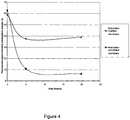
- An initial modulationwas determined at zero time from a 3-point calibration in isotonic phosphate buffered saline and this was compared with modulations calculated from further 3-point calibrations following exposure of the sensors to human blood for both 5 and 20 hours. The results are depicted in Figure 4 .
- Figure 4shows comparatively the fluorescent signal intensity of each sensor. It can be seen that the decrease in fluorescent intensity with time is much greater for the sensor that has the unmodified membrane than that for the sensor with the modified membrane.
- the modified membranehas much better barrier properties to protein and glycated proteins that are present in human blood, resulting in significantly improved sensitivity of the sensor.
Landscapes
- Health & Medical Sciences (AREA)
- Life Sciences & Earth Sciences (AREA)
- Physics & Mathematics (AREA)
- Engineering & Computer Science (AREA)
- Chemical & Material Sciences (AREA)
- Pathology (AREA)
- Molecular Biology (AREA)
- Biomedical Technology (AREA)
- General Health & Medical Sciences (AREA)
- Immunology (AREA)
- Hematology (AREA)
- Medical Informatics (AREA)
- Surgery (AREA)
- Animal Behavior & Ethology (AREA)
- Urology & Nephrology (AREA)
- Public Health (AREA)
- Veterinary Medicine (AREA)
- General Physics & Mathematics (AREA)
- Optics & Photonics (AREA)
- Heart & Thoracic Surgery (AREA)
- Biochemistry (AREA)
- Analytical Chemistry (AREA)
- Biophysics (AREA)
- Chemical Kinetics & Catalysis (AREA)
- Diabetes (AREA)
- Microbiology (AREA)
- Food Science & Technology (AREA)
- Medicinal Chemistry (AREA)
- Cell Biology (AREA)
- Biotechnology (AREA)
- Spectroscopy & Molecular Physics (AREA)
- Emergency Medicine (AREA)
- Plasma & Fusion (AREA)
- Measurement Of The Respiration, Hearing Ability, Form, And Blood Characteristics Of Living Organisms (AREA)
- Investigating Or Analysing Biological Materials (AREA)
- Investigating, Analyzing Materials By Fluorescence Or Luminescence (AREA)
- Separation Using Semi-Permeable Membranes (AREA)
Description
- The invention relates to glucose sensors, methods for making such glucose sensors and methods for detecting or determining the quantity of glucose in a sample.
- It has been known for some time that boronates form reversible 5 membered ring complexes with saccharides. More recently, this property of boronates has been utilised in the development of sensors for the measurement of glucose in biological fluids. For example, a sensor may comprise a glucose receptor (the boronic acid) and a fluorophore that acts as the transmitter of the signal. These indicator chemistries can readily be immobilised onto an optical fibre of appropriate diameter, which can then be placed into body fluids or tissue to measure glucose.
- It has been known for some time that boronic acids reversibly complex with glycoylated and glycated proteins. Although attempts have been made to devise sensing boronic acid chemistries that are selective it is obvious that glycated proteins represent potential interferents in the determination of glucose in body fluids when boronic acids are used as the sensor. Also other middle to high molecular weight endogenous materials have the potential to interfere with the boronic acid receptor by acting as quenchers of the transmitting fluorophore. There is therefore a need for a means to eliminate these interferents from a glucose sensor using boronic acid/fluorophore indicating chemistry.
- The invention addresses the above-described problem by sheathing the boronic acid/fluorophore glucose indicating chemistry with a protective barrier layer which is permeable to glucose but which restricts the passage of large molecular weight molecules such as proteins and glycated proteins. Accordingly, the present invention provides an optical glucose sensor comprising
- a sensing region comprising a boronic acid receptor for binding to glucose and a fluorophore associated with said receptor;
- an optical waveguide for directing incident light onto the sensing region; and
- a hydrophilic, polymeric, glucose-permeable barrier layer comprising a semipermeable membrane which is provided on at least a part of the sensing region, wherein a hydrophilic polymer and/or a negatively charged polymer is present within the pores of the membrane, the membrane being formed by generating the hydrophilic and/or negatively charged polymerin situ by diffusing a hydrophilic and/ or negatively charged monomer into the pores of a membrane and initiating polymerisation;
- The barrier layer is capable of restricting the passage of proteins and glycated proteins into the sensing region. Typically, the barrier layer is substantially impermeable to proteins and glycated proteins. For example, the barrier layer may restrict or prevent the passage of, or be substantially impermeable to, molecules having a molecular weight of greater than 6000, preferably greater than 5000, more preferably greater than 4000.
- The barrier layer comprises a semi-permeable membrane, for example a dialysis membrane. The pore size of the membrane can be selected so as to ensure permeability to glucose but to restrict or prevent the passage of larger macromolecules such as proteins and glycated proteins. Use of a dialysis membrane having a molecular weight cut off (MWCO) of from 1000 to 5000 eliminates potential interferents such as insulin, beta-microglobulin and albumin and their glycated derivatives.
- A hydrophilic and/or negatively charged polymer is present within the pores of the membrane. This is achieved via in situ polymerisation, within the pores of the membrane, of a monomer mixture comprising one or more hydrophilic monomers and/or one or more negatively charged monomers. The resulting membrane is particularly effective as a barrier to proteins and glycated proteins due to its hydrophilicity and/or negative charge and has the further advantage that the polymerisation process may be used to control, and to further decrease, the pore size of the membrane.
- The present invention also provides a method of detecting or quantifying the amount of glucose in a sample, comprising inserting into the sample a glucose sensor according to the invention, providing incident light to the sensing region of the sensor and detecting the emission pattern of the fluorophore.
- Further preferred features and embodiments of the invention are described in the accompanying description and the appended claims.
Figures 1 and 1a depict a sensor of the invention incorporating an optical fibre and a monitor for such a sensor.Figures 2 and 3 depict various embodiments of a sensing region of a sensor of the invention.Figure 4 shows a graph of the glucose calibration of a fibre optic sensor sheathed with a polyether sulphone hollow fibre dialysis membrane which is (a) modified by the in-situ polymerisation process described in Example 1 or (b) unmodified. The calibrations were run in human blood.- As used herein the term hydrophilic indicates a material which has an affinity for water. The glucose sensors of the invention are typically used to detect or quantify glucose in an aqueous solution. The hydrophilic barrier layer on the outside of the sensing region therefore has an affinity for the aqueous solution in which the glucose is dissolved. Further, the hydrophilicity of the barrier layer assists in repelling plasma proteins when a sensor is used in a bodily fluid, in particular in blood.
- As used herein a glucose permeable barrier layer is a material which allows the passage of glucose through the layer but which restricts the passage of proteins and glycated proteins.
- The present invention is envisaged for use with any optical glucose sensor using boronic acid/fluorophore glucose sensing chemistry. Fibre optic sensors are particularly envisaged, but the present invention may also be used with sensors having different types of optical waveguide. Glucose sensing is typically carried out in bodily fluids such as interstitial tissue or blood, although sensing of any aqueous solution may be carried out using the sensors of the invention. The particular embodiments described herein are envisaged for use as invasive sensors for insertion into a blood vessel. However, the present invention is not limited to such invasive sensors. Non-invasive sensors forin vitro use, implantable sensors and subcutaneous sensors are also within the scope of the present invention.
- An example of a sensor of the invention incorporating an optical fibre is depicted in
Figures 1 and 1a . Thesensor 1 comprises anoptical fibre 2 including asensing region 3 at its distal end. In the case of an invasive sensor,fibre 2 is adapted for insertion into a patient, for example insertion into a blood vessel through a cannula. The sensing region 3 (depicted in more detail inFigures 2 and 3 ) contains a cell orchamber 7 in which the indicator chemistry is contained. The optical fibre extends throughcable 4 toconnector 5 which is adapted to mate with anappropriate monitor 8. The monitor typically includes furtheroptical cable 4a that mates with the connector at 5a and at the other bifurcates to connect to (a) an appropriate source of incident light for theoptical sensor 9 and (b) a detector for thereturn signal 10. - In one embodiment, the sensor of the invention is a disposable sensor. The sensor is typically adapted to be connected to a non-disposable monitor comprising a
light source 9 anddetector 10. - As depicted in
Figure 2 , thesensing region 3 incorporates acell 7 in the form of a chamber within the fibre. The cell may take any form, as long as it enables the indicator chemistry to be contained in the path of the incident light directed by the waveguide, here a fibre. Thus, the cell may be attached to the distal end of the fibre or waveguide or may be in the form of a chamber within the fibre having any desired shape. - The
cell 7 contains the indicator chemistry, namely a boronic acid receptor for binding glucose and a fluorophore associated with the receptor. The emission pattern (e.g. the wavelength, intensity, lifetime) of the fluorophore is altered when the analyte is bound to the receptor allowing optical detection of glucose. The receptor and fluorophore may be directly bonded to one another as a receptor-fluorophore construct. Examples of suitable fluorophores include anthracene, pyrene and derivatives thereof. Examples of suitable boronic acid receptors are compounds having at least one, preferably two boronic acid groups. - In a preferred embodiment, the receptor is a group of formula (I)

- Varying the length of the spacer Sp alters the selectivity of the receptor. Typically, a C6-alkylene chain provides a receptor which has good selectivity for glucose.
- Further details of such receptors are found in
US, 6,387,672 . - The receptor and fluorophore are typically bound to one another and may further be bound to a polymeric matrix. A hydrogel is an example of a suitable polymeric matrix.
- The
sensing region 3 of the glucose sensor has one ormore openings Figures 2 and 3 , the barrier layer is provided over theentire sensing region 3. Alternatively, however, the barrier layer may be provided on only part of the sensing region, for example only acrossopenings - The sensor is typically designed such that any openings into the sensing region through which glucose can pass are covered with the barrier layer. This ensures that protein adsorption is restricted at least at the openings into the sensing region. In a preferred embodiment, however, the entire sensing region, or the entire surface of the sensor which is to come into contact with the sample under test, is coated or sheathed with the barrier layer. This helps to prevent protein adsorption on any surface of the sensor and improves the biocompatibility of the sensor in the case of invasive or implantable sensors.
- As depicted in
Figure 2 , the barrier layer BL may be applied directly onto the sensing region, here onto the tip of the optical fibre. In an alternative embodiment depicted inFigure 3 , thesensing region 3 is provided within aseparate support 11 and the barrier layer is provided on thesupport 11. The use of a separate support structure provides additional strength to the barrier layer which may itself be fragile. Holes or pores are provided in the support to enable glucose to enter thesensing region 3. Suitable support structures are polymer tubes which are perforated with holes, for example by laser ablation. Microporous hollow fibres which are commonly used in medical oxygenators and which have pores of approximately 0.2 micron in diameter provide appropriate support structures for use with fibre optic sensors. Alternative support structures are woven sheaths of polymeric or metallic materials such as those described inWO2009/019470 . - If desired, the barrier layer may be adhered to the surface of the sensor e.g. to the optical fibre itself or to support 11. This can be achieved by application of a suitable adherent such as cyanoacrylate. Alternatively, where the sensor surface and the barrier layer material are appropriate, the joint between the barrier layer and the sensor can be thermoformed, e.g. at Ja, Jb of
Figures 2 and 3 . - The barrier layer is formed from a polymeric material which is hydrophilic, permeable to glucose and which offers some restriction to the passage of high molecular weight materials such as proteins.
- A hydrogel as used herein is a hydrophilic polymeric matrix which swells when placed in water. When placed in water, water is dispersed throughout the matrix. Examples of suitable hydrogel materials include cross-linked polyacrylamide, polydimethyl acrylamide, poly hydroxyl ethylmethacylate, polyvinyl pyrrolidone, poly ethylene glycol acrylates and poly ethylene glycol methacrylates. The hydrogel is typically coated directly onto the outer surface of the sensing region, in the case of an optical fibre it is typically coated directly onto the tip of the optical fibre. The hydrogel may incorporate additional materials such as anions, as described further below.
- The barrier layer is formed by a semi-permeable membrane such as a dialysis membrane. Dialysis membranes are semi-permeable membranes that separate molecules by virtue of their size, shape, hydration and polarity. They are particularly suitable for use in the present invention since their pore size allows glucose to permeate the membrane but is too small to allow the passage of proteins. Dialysis membranes are usually in the form of hollow fibres and are available in materials such as polyarylethersulphone, polyamide, polycarbonate, polyacrylonitrile, polysulphone, polyethersulphone, polyvinylidenefluoride and cellulosic materials or mixtures or modifications thereof.
- In another aspect of this embodiment, which is described in detail below, the semi-permeable membrane is formed from a microporous membrane having polymers incorporated within the pores of the membrane (e.g. byin situ polymerisation within the pores). The presence of the polymers within the pores causes a reduction in the pore size such that the membrane acts as a semi-permeable membrane, forming a barrier to high molecular weight materials such as proteins and glycated proteins. Microporous membranes suitable for use in this aspect typically have a pore size in the region of 0.1 to 10µm, e.g. up to 2µm or up to 1µm, for example about 0.2µm.
- Semi-permeable membranes are available with different pore sizes relating to the molecular weight cut-off (MWCO) of the membrane. The molecular weight cut-off indicates the maximum molecular weight of molecule which can pass through the pores of the membrane. Small pore sizes are termed "low flux" with a low MWCO and a larger pore size is termed "high flux" with a high MWCO. Proteins are macromolecules that range in molecular weight from around 6,000 for insulin to 11,800 for beta-microglobulin, 66,200 for albumin to 970,000 for IGN. Thus to eliminate these potential interferents and their derivatives a low MWCO material should be chosen that does not allow materials of molecular weight 6,000 or higher to pass through but does allow glucose (MW180) to pass. The pore size should, however, be maximised whilst eliminating these interferents in order to provide a maximum flux of glucose into the sensor.
- In order to provide an acceptable response time for an intravascular sensor which continuously measures glucose, the membrane should preferably be selected so as to provide a 90% response time of no more than three minutes, preferably no more than two-and-a-half minutes. Preferred membranes have a MWCO of at least 1,000 and preferably no more than 5,000. For example, the MWCO may be at least 1,500 or at least 2,000, for example no more than 4,000. Preferred effective pore sizes (preferred pore sizes) are 1 to 20nm, preferably 1 to 10nm, for example about 6nm.
- In the embodiment of the invention described below in which polymerisation is carried out within the pores of the membrane, the polymerisation step decreases the effective MWCO and pore size of the membrane. The preferred MWCO and pore sizes described above refer to the final membrane for use in the glucose sensor and are therefore the effective MWCO and effective pore sizes of the resulting membrane followingin situ polymerisation.
- The sensor may be directly coated or sheathed with the membrane, but it is preferred that the membrane is provided on a support, e.g. a tube into which the sensor is placed (see
Figure 3 ). In one embodiment, the sensing region of the sensor is coated with a hydrogel and the membrane, e.g. the dialysis membrane barrier layer is placed onto the hydrogel layer. - Some of the materials used as dialysis membrane materials are inherently hydrophobic, for example polysulphone, polyethersulphone and polyvinylidenefluoride. In accordance with the present invention, the barrier layer is hydrophilic in order to avoid adsorption of serum proteins onto the layer. Materials which are by nature hydrophobic are therefore modified in order to provide some hydrophilic character, for example by grafting hydrophilic groups to the polymer or graft polymerisation using hydrophilic monomers. Suitable hydrophilic groups and monomers include 2-hydroxy-ethyl methacrylate, (meth)acrylic acid and hydroxyl- or sulphonyl-bearing groups or monomers.
- Graft polymerisation can be achieved in accordance with the techniques ofM Belfort et al. (J Membr Sci. 1996.111. 193-215). This describes the use of radiation techniques to graft polymerise hydrophilic monomers such as 2-hydroxy-ethyl methacrylate, acylic acid, and methacrylic acid onto polysulphone membrane surfaces, which resulted in membranes with an increased flux. Alternative techniques are described byHiguchiet et al. (J. Membr Sci. 1991.57.175-185.) in which sulphonyl and hydroxyl end-terminated groups are chemically grafted to polysulphone membrane surfaces leading to reduced protein adsorption.
- Hydrophilic membranes may alternatively be provided by the use of amphiphilic graft or comb polymers as surface modifying additives for the membranes (Mayes et al. Macromolecules. 2002.35.7652-61.). Similarly, polyethylene glycol groups can be incorporated into a polysulphone polymer as described byMayes et al. (Biomaterials. 2006. 27. 856-865.). These membranes have shown significant resistance to protein adsorption and cell attachment. Examples of suitable membranes are those described in
US 6,193,077 . These are non-cracking hydrophilic macroporous (0.1 to 100 micron pores) polyether sulphone membranes prepared by coating the surface with an aqueous solution of a preformed high molecular weight polyalkylene oxide polymer (25,000 to 1,000,000 daltons) and a polyfuntional monomer followed by plasma polymerisation. Further examples of suitable membranes are those described inUS 5,468,390 . These membranes are arylpolysulphone membranes which have been modified by polymerising monofunctional monomers onto the surface without the use of an initiator. - Described here but not part of the invention is an embodiment wherein hydrophilic character is provided by incorporating one or more hydrophilic polymers during wet spinning formation of a dialysis membrane. Dialysis membranes are typically produced by spinning a solution of an appropriate polymer in order to form the desired membrane structure (e.g. a hollow fibre dialysis membrane, which can be used to sheath the sensor). In this embodiment, a hydrophilic polymer is added to the polymer solution prior to spinning, thus leading to a dialysis membrane formed of the main membrane polymer(s) (e.g. polysulphone, polyethersulphone or polyvinylidene fluoride) as well as the hydrophilic polymer(s). The resulting membrane accordingly comprises hydrophilic areas or pockets which allow water to pass through. The hydrophilicity of the resulting membrane can be controlled by varying the amount of hydrophilic polymer which is incorporated. Typically, hydrophilic polymer makes up about 10% of the total polymer content of the solution prior to spinning.
- A hydrophilic polymer as used herein is a polymer comprising units having hydrophilic character, for example, which is prepared from a mixture of monomers wherein at least one of the monomers has hydrophilic character. Examples of suitable hydrophilic polymers are polyethylene glycol, polyethylene oxide and polyvinylpyrrolidone.
- In a further alternative embodiment, hydrophilic character is provided by provision of a hydrophilic polymer, typically having functional groups with known protein repelling characteristics, within the pores of the membrane. The provision of the polymer within the pores of the membrane is achieved by diffusing one or more suitable hydrophilic monomers into the membrane (e.g. pore size 6 to 20 nm) and initiating polymerisation, for example by applying UV activation in the presence of an initiator. This leads to polymerisation occurring within the pores of the membrane and the resulting polymer is trapped within the pores. If desired, the diffusion and polymerisation steps can be repeated one or more times to increase the amount of polymer formed within the membrane pores. The membrane is, for example, in the form of a hollow fibre dialysis membrane such that the resultant tube could be used to sheath the sensor providing the necessary barrier properties.
- In an alternative aspect of this embodiment, the hydrophilic polymer is provided within the pores of a microporous membrane, e.g. a microporous hollow fibre (typical pore size 0.1 to 10µm, e.g. up to 2µm or up to 1µm, for example about 0.2µm). The inherent decrease in pore size caused by thein situ polymerisation within the membrane pores provides a membrane which is an appropriate barrier to interferents such as proteins and glycated proteins.
- Where a microporous membrane is used, this may be applied onto a
separate support 11 as depicted inFigure 3 . Alternatively the microporous membrane itself may function both as the support as well as the barrier layer. - In this embodiment, the functional group integrated into the membrane (e.g. mircroporous membrane or dialysis membrane) is preferably polyethylene glycol or polyethylene oxide which have known protein repelling characteristics. Suitable hydrophilic monomers for use in this embodiment therefore include polyethyleneglycol dimethacrylate, polyethyleneglycol dimethacrylamide, polyethylenglycol diacrylate and polyethyleneglycol diacrylamide, or a combination thereof. Polyethyleneglycol dimethacrylate is preferred. Polyethylene glycol dimethacrylate and polyethyleneglycol diacrylate, and various derivatives, of varying molecular weights can be readily obtained from Sigma-Aldrich, UK.
- Typically, the polymerisation mixture which is diffused into the membrane pores comprises a chain extending monomer in addition to the hydrophilic monomer(s). Examples of suitable chain extenders include di(meth)acrylate and di(meth)acrylamide.
- Membranes in accordance with this embodiment of the invention have been shown to provide significant inhibition to protein adsorption and enhancement as a barrier to boronic acid receptor/fluorophore interferents. In addition, such treated membranes provide the ability to decrease and to fine tune the membrane pore size. Since the hydrophilic monomer(s) are diffused into the pores of the membrane and polymerised in-situ, the pore size will decrease and hence the MWCO will decrease. This decrease in pore size provides a membrane which acts as a more efficient barrier to proteins and glycated proteins. Hence, by variation of the concentration of the diffusing monomer solution and crosslinker, and the number of times the diffusion and polymerisation is carried out, the pore size and MWCO can be adjusted and determined by experiment. MWCO can be determined by the diffusion of monodisperse materials of known molecular weights with a fluorescent molecule attached. Materials of gradually increasing molecular weight are passed through the membrane and the diffusion breakthrough can be determined using a fluorimeter as a detector. Examples of suitable monodisperse materials are fluorescein-labelled dextrans available from Sigma-Aldrich in a variety of molecular weights.
- In a further aspect of the invention, the effectiveness of the barrier layer can be enhanced by incorporating a negative charge into the layer. Proteins are negatively charged at physiological pH so the incorporation of a negative charge into the barrier layer acts as a repellent to proteins including glycated proteins, or other negatively charged interferents. This can be achieved by incorporating a negatively charged monomer or polymer or an anion into the barrier layer.
- Anions are particularly suitable for incorporation into a hydrogel. Examples of suitable anions include halides, sulfonate, carboxylate, alkoxide.
- Negatively charged monomers or polymers are suitable for incorporation into a membrane (e.g. microporous membrane or dialysis membrane) barrier layer. Suitable negatively charged monomers or polymers include potassium sulphopropylmethacrylate, acrylic or methacylic acids or their corresponding polymers.
- One or more negatively charged monomer(s) such as potassium sulphopropylmethacrylate can be diffused into the membrane (e.g. microporous membrane or dialysis membrane) and then polymerisedin situ. Polymerisation can be carried out in a similar manner to that discussed above with regard to hydrophilic monomers such as polyethyleneglycol dimethacrylate. This process leads to the formation of a negatively charged polymer which is trapped by virtue of its size, or through copolymerisation with hydrophilic monomers, within the pores of the membrane (e.g. microporous membrane or dialysis membrane). Such polymerisation may be carried out using one or more negatively charged monomers alone, or using a mixture of one or more hydrophilic monomers as described above and one or more negatively charged monomers.
- In an alternative embodiment, the negatively charged material is heparin. This has the advantage that the negative charge carried on the heparin molecule repels proteins, but has the added benefit of being antithrombogenic. Heparin can be incorporated into a hydrogel or grafted to, or polymerised with, a membrane (e.g. microporous membrane or dialysis membrane).
- The sensor is manufactured by providing a sensing region comprising a boronic acid receptor for binding to glucose and a fluorophore associated with said receptor; providing an optical waveguide for directing incident light onto the sensing region; and providing a hydrophilic, polymeric, glucose-permeable barrier layer on at least a part of the sensing region; and wherein the sensor is adapted so that glucose enters the sensing region of the sensor through said barrier layer.
- The barrier layer comprises a semi-permeable membrane and the method comprises diffusing one or more monomers selected from hydrophilic and negatively charged monomers into the pores of the membrane (e.g. a dialysis membrane or a microporous membrane) and initiating polymerisation. This results in a hydrophilic and/or negatively charged polymer being formed within the pores of the membrane (e.g. the microporous or dialysis membrane) and a decrease in pore size. Polymerisation to form the hydrophilic or negatively charged polymer can be carried out either before or after applying the membrane (e.g. microporous membrane or dialysis membrane) to the sensing region of the sensor.
- A polyethersulphone hollow fibre dialysis membrane was dipped into a polymerisation mixture as set out below for 10 minutes and then polymerisation was initiated by UV at 240nm for 30seconds at a power setting of 8.3 milliwatts. The resultant membrane was washed in phosphate buffer solution at 37 C for 12 hours, rinsed in distilled water and then air dried.
Polymerisation mixture 2.00g Polyethylene glycoldimethacrylate(600) 1.00g Dimethylacrylamide 0.50g Potassium propylsulphomethacrylate 0.02g Irgacure 651 0.20g Triton X 3.50 Water - The resultant membrane contains a polymer having units derived from dimethyl acrylamide, potassium sulphopropylmethacrylate, and crosslinked with polyethylene glycol dimethacrylate, within its pores.
- The sensing region of a fibre optic glucose sensor utilising a diboronic acid/fluorophore indicator in accordance with those described in
US 6,387,672 was sheathed with the above membrane and used to determine glucose concentrations of human blood. For comparison, experiments in the same blood samples were also carried out using a sensor identical to that described above except that it is sheathed with unmodified polyethersulphone hollow fibre dialysis membrane. - The sensors were tested by excitation with an appropriate excitation wavelength and measurement of the emission signal from the sensor chemistry. A response curve to glucose was defined by varying the glucose concentration though three points, the curve was further defined by a set of three constants which allows the calculation of glucose concentration at any given measured emission intensity. The modulation is a measure of the intensity change for a given change in the glucose concentration and is hence a measure of the sensitivity of the sensor. An initial modulation was determined at zero time from a 3-point calibration in isotonic phosphate buffered saline and this was compared with modulations calculated from further 3-point calibrations following exposure of the sensors to human blood for both 5 and 20 hours. The results are depicted in
Figure 4 . Figure 4 shows comparatively the fluorescent signal intensity of each sensor. It can be seen that the decrease in fluorescent intensity with time is much greater for the sensor that has the unmodified membrane than that for the sensor with the modified membrane. The modified membrane has much better barrier properties to protein and glycated proteins that are present in human blood, resulting in significantly improved sensitivity of the sensor.- The present invention has been described with reference to a number of particular embodiments and examples. The invention is not, however, limited to these specific embodiments and examples.

Claims (15)
- An optical glucose sensor comprising:- a sensing region comprising a boronic acid receptor for binding to glucose and a fluorophore associated with said receptor;- an optical waveguide for directing incident light onto the sensing region; and- a hydrophilic, polymeric, glucose-permeable barrier layer comprising a semi-permeable membrane which is provided on at least a part of the sensing region, wherein a hydrophilic polymer and/or a negatively charged polymer is present within the pores of the membrane, the membrane being formed by generating the hydrophilic and/or negatively charged polymerin situ by diffusing a hydrophilic and/ or negatively charged monomer into the pores of a membrane and initiating polymerisation;wherein the sensor is adapted so that glucose enters the sensing region of the sensor through said barrier layer.
- A glucose sensor according to claim 1, wherein the membrane restricts the passage of proteins and glycated proteins having a molecular weight of 6000 or greater.
- A glucose sensor according to claim 1 or 2, wherein the membrane restricts the passage of proteins and glycated proteins having a molecular weight of 5000 or greater.
- A glucose sensor according to one of claims 1 to 3, wherein the membrane has an effective pore size of from 1 to 20nm.
- A glucose sensor according to any one of claims 1 to 4, wherein a negatively charged polymer is present within the pores of the membrane, the membrane being formed by diffusing a negatively charged monomer into the pores of a membrane and initiating polymerisation.
- A glucose sensor according to any one of claims 1 to 5, wherein the semi-permeable membrane is formed by diffusing a hydrophilic and/or negatively charged monomer into the pores of a dialysis membrane and initiating polymerisation.
- A glucose sensor according to any one of claims 1 to 5, wherein the semi-permeable membrane is formed by diffusing a hydrophilic and/or negatively charged monomer into the pores of a microporous membrane and initiating polymerisation.
- A glucose sensor according to any one of the preceding claims wherein the barrier layer incorporates an anion or a negatively charged group or molecule.
- A glucose sensor according to any one of the preceding claims, wherein the barrier layer comprises heparin.
- A glucose sensor according to any one of the preceding claims wherein the sensing region is provided within a support and the barrier layer is provided on said support.
- A method of manufacturing a glucose sensor according to any one of the preceding claims, which comprises- providing a sensing region comprising a boronic acid receptor for binding to glucose and a fluorophore associated with said receptor;- providing an optical waveguide for directing incident light onto the sensing region; and- providing a hydrophilic, polymeric, glucose-permeable barrier layer on at least a part of the sensing region wherein the barrier layer is a semi-permeable membrane and the method comprises diffusing hydrophilic and/ or negatively charged monomer(s) into the pores of a membrane and initiating polymerisation, to provide a semi-permeable membrane comprising a hydrophilic and/or negatively charged polymer within the pores of the membrane;wherein the sensor is adapted so that glucose enters the sensing region of the sensor through said barrier layer.
- A method according to claim 11, wherein the method comprises diffusing hydrophilic and/or negatively charged monomer(s) into the pores of a microporous membrane and initiating polymerisation.
- A method according to claim 11 wherein the method comprises diffusing hydrophilic and/or negatively charged monomer(s) into the pores of a dialysis membrane and initiating polymerisation.
- A method according to claim 11, wherein the barrier layer is a dialysis membrane produced by spinning a polymer solution comprising at least one hydrophilic and/or negatively charged polymer.
- A method of detecting and/or quantifying the amount of glucose in a sample, comprising inserting into the sample a glucose sensor according to any one of claims 1 to 10, providing incident light to the sensing region of the sensor and detecting the emission pattern of the fluorophore.
Applications Claiming Priority (2)
| Application Number | Priority Date | Filing Date | Title |
|---|---|---|---|
| US30497110P | 2010-02-16 | 2010-02-16 | |
| PCT/GB2011/000209WO2011101626A1 (en) | 2010-02-16 | 2011-02-15 | Barrier layer for glusose sensor |
Publications (2)
| Publication Number | Publication Date |
|---|---|
| EP2537034A1 EP2537034A1 (en) | 2012-12-26 |
| EP2537034B1true EP2537034B1 (en) | 2019-01-02 |
Family
ID=44009750
Family Applications (1)
| Application Number | Title | Priority Date | Filing Date |
|---|---|---|---|
| EP11704831.4AActiveEP2537034B1 (en) | 2010-02-16 | 2011-02-15 | Barrier layer for glucose sensor |
Country Status (6)
| Country | Link |
|---|---|
| US (1) | US9151764B2 (en) |
| EP (1) | EP2537034B1 (en) |
| JP (1) | JP6008370B2 (en) |
| AU (1) | AU2011217068B2 (en) |
| ES (1) | ES2716548T3 (en) |
| WO (1) | WO2011101626A1 (en) |
Families Citing this family (17)
| Publication number | Priority date | Publication date | Assignee | Title |
|---|---|---|---|---|
| US9517023B2 (en) | 2009-06-01 | 2016-12-13 | Profusa, Inc. | Method and system for directing a localized biological response to an implant |
| US10010272B2 (en) | 2010-05-27 | 2018-07-03 | Profusa, Inc. | Tissue-integrating electronic apparatus |
| CA3012355C (en) | 2010-10-06 | 2023-05-16 | Profusa, Inc. | Tissue-integrating sensors |
| AU2012206476B2 (en) | 2011-01-11 | 2017-05-11 | Lightship Medical Limited | Glucose sensor molecule |
| CN103533884B (en) | 2011-03-15 | 2016-06-01 | 传感技术股份有限公司 | The integrated catalytic protection of oxidation sensitive material |
| EP2744909B1 (en)* | 2011-08-17 | 2021-09-22 | Baxter International Inc. | Method for preparing a barrier layer for a glucose sensor |
| AU2013234126A1 (en)* | 2012-03-15 | 2014-09-25 | Lightship Medical Limited | Sensor for detecting the amount of analyte in a sample |
| US20130344619A1 (en) | 2012-06-21 | 2013-12-26 | Lightship Medical Limited | Glucose sensor |
| WO2014043204A1 (en)* | 2012-09-14 | 2014-03-20 | Senseonics, Incorporated | Integrated catalytic protection of oxidation sensitive materials |
| US9963556B2 (en) | 2013-09-18 | 2018-05-08 | Senseonics, Incorporated | Critical point drying of hydrogels in analyte sensors |
| US9739746B1 (en) | 2013-12-23 | 2017-08-22 | Google Inc. | Analyte sensor incorporating negatively charged moieties |
| US9855359B2 (en) | 2013-12-23 | 2018-01-02 | Verily Life Sciences Llc | Analyte sensors with ethylene oxide immunity |
| WO2016196516A1 (en) | 2015-06-03 | 2016-12-08 | William Kenneth Ward | Measurement of glucose in an insulin delivery catheter by minimizing the adverse effects of insulin preservatives |
| WO2018119400A1 (en) | 2016-12-22 | 2018-06-28 | Profusa, Inc. | System and single-channel luminescent sensor for and method of determining analyte value |
| US10145143B1 (en) | 2017-06-06 | 2018-12-04 | Schlage Lock Company Llc | Lever return mechanism using magnets |
| CA3181264A1 (en)* | 2020-07-07 | 2022-01-13 | Alexander Steck | Analyte sensor and its manufacturing |
| CA3199213A1 (en)* | 2020-11-18 | 2022-05-27 | Cercacor Laboratories, Inc. | Glucose sensors and methods of manufacturing |
Family Cites Families (29)
| Publication number | Priority date | Publication date | Assignee | Title |
|---|---|---|---|---|
| US3975350A (en)* | 1972-08-02 | 1976-08-17 | Princeton Polymer Laboratories, Incorporated | Hydrophilic or hydrogel carrier systems such as coatings, body implants and other articles |
| JPS5778908A (en)* | 1980-10-31 | 1982-05-17 | Kuraray Co Ltd | Separating membrane excellent in acid resistance |
| US4618533A (en)* | 1984-11-30 | 1986-10-21 | Millipore Corporation | Porous membrane having hydrophilic surface and process |
| DK193287A (en)* | 1986-04-16 | 1987-10-17 | Alcan Int Ltd | COMPOSITE MEMBRANE |
| JP3092864B2 (en)* | 1991-05-09 | 2000-09-25 | 東燃化学株式会社 | Separation membrane and separation method |
| EP0623150A4 (en)* | 1992-11-19 | 1999-08-25 | Univ Case Western Reserve | Nonthrombogenic implant surfaces. |
| US5468390A (en) | 1992-11-23 | 1995-11-21 | Rensselaer Polytechnic Institute | Low fouling ultrafiltration and microfiltration aryl polysulfone |
| JP3084292B2 (en)* | 1994-07-28 | 2000-09-04 | ミリポア コーポレイション | Porous composite membrane and method |
| US6002954A (en)* | 1995-11-22 | 1999-12-14 | The Regents Of The University Of California | Detection of biological molecules using boronate-based chemical amplification and optical sensors |
| US6193077B1 (en) | 1999-02-08 | 2001-02-27 | Osmonics, Inc. | Non-cracking hydrophilic polyethersulfone membranes |
| KR100771711B1 (en)* | 1999-08-27 | 2007-10-30 | 엠-바이오테크, 인코포레이티드 | Glucose biosensor |
| WO2001075450A2 (en) | 2000-04-04 | 2001-10-11 | The Regents Of The University Of California | Fluorescent lifetime assays for non-invasive quantification of analytes |
| US8133698B2 (en)* | 2000-05-15 | 2012-03-13 | Silver James H | Sensors for detecting substances indicative of stroke, ischemia, infection or inflammation |
| US6387672B1 (en) | 2000-12-04 | 2002-05-14 | Beckman Coulter, Inc. | Photo-induced electron transfer fluorescent sensor molecules |
| US7470420B2 (en)* | 2000-12-05 | 2008-12-30 | The Regents Of The University Of California | Optical determination of glucose utilizing boronic acid adducts |
| US6627177B2 (en)* | 2000-12-05 | 2003-09-30 | The Regents Of The University Of California | Polyhydroxyl-substituted organic molecule sensing optical in vivo method utilizing a boronic acid adduct and the device thereof |
| US6952603B2 (en)* | 2001-03-16 | 2005-10-04 | Roche Diagnostics Operations, Inc. | Subcutaneous analyte sensor |
| JP2005315871A (en)* | 2004-03-31 | 2005-11-10 | Terumo Corp | Intracorporeal substance measuring assembly, manufacturing method for intracorporeal substance measuring assembly, and embedded type substance sensor |
| EP1885871B1 (en)* | 2005-05-17 | 2012-05-30 | Radiometer Medical ApS | Enzyme sensor with a cover membrane layer covered by a hydrophilic polymer |
| GB0612834D0 (en)* | 2006-06-28 | 2006-08-09 | Glysure Ltd | Sensor calibration |
| US20080214912A1 (en) | 2007-01-10 | 2008-09-04 | Glucose Sensing Technologies, Llc | Blood Glucose Monitoring System And Method |
| JP2008209204A (en)* | 2007-02-26 | 2008-09-11 | Citizen Holdings Co Ltd | Concentration measuring instrument |
| WO2008141241A1 (en) | 2007-05-10 | 2008-11-20 | Glumetrics, Inc. | Equilibrium non-consuming fluorescence sensor for real time intravascular glucose measurement |
| JP5675350B2 (en)* | 2007-07-11 | 2015-02-25 | メドトロニック ミニメド インコーポレイテッド | Polyviologen compound, method for synthesizing the compound, glucose sensor, and composition for measuring glucose |
| GB0715590D0 (en) | 2007-08-09 | 2007-09-19 | Glysure Ltd | Sensing apparatus |
| JP5631215B2 (en)* | 2007-11-21 | 2014-11-26 | メドトロニック ミニメド インコーポレイテッド | Blood sugar management maintenance system |
| US20100055188A1 (en)* | 2008-08-28 | 2010-03-04 | Dong June Ahn | Nano-valves for small-molecule drug delivery |
| GB0906318D0 (en) | 2009-04-09 | 2009-05-20 | Glysure Ltd | Fluorophore and fluorescent sensor compound containing same |
| WO2011101624A1 (en) | 2010-02-19 | 2011-08-25 | Glysure Ltd | Indicator system for fibre optic sensor |
- 2011
- 2011-02-15EPEP11704831.4Apatent/EP2537034B1/enactiveActive
- 2011-02-15JPJP2012553393Apatent/JP6008370B2/ennot_activeExpired - Fee Related
- 2011-02-15USUS13/578,893patent/US9151764B2/enactiveActive
- 2011-02-15WOPCT/GB2011/000209patent/WO2011101626A1/enactiveApplication Filing
- 2011-02-15ESES11704831Tpatent/ES2716548T3/enactiveActive
- 2011-02-15AUAU2011217068Apatent/AU2011217068B2/ennot_activeCeased
Non-Patent Citations (1)
| Title |
|---|
| None* |
Also Published As
| Publication number | Publication date |
|---|---|
| US9151764B2 (en) | 2015-10-06 |
| JP6008370B2 (en) | 2016-10-19 |
| ES2716548T3 (en) | 2019-06-13 |
| JP2013519895A (en) | 2013-05-30 |
| EP2537034A1 (en) | 2012-12-26 |
| US20130040404A1 (en) | 2013-02-14 |
| WO2011101626A1 (en) | 2011-08-25 |
| AU2011217068B2 (en) | 2014-11-06 |
| AU2011217068A1 (en) | 2012-09-06 |
Similar Documents
| Publication | Publication Date | Title |
|---|---|---|
| EP2537034B1 (en) | Barrier layer for glucose sensor | |
| US5326531A (en) | CO2 sensor using a hydrophilic polyurethane matrix and process for manufacturing | |
| KR101510488B1 (en) | Hydrogel implants for the detection of metabolites in body tissues | |
| US8715589B2 (en) | Sensors with thromboresistant coating | |
| ES2966036T3 (en) | Biocompatibility coating for continuous measurement of analytes | |
| CA2738366C (en) | Implantable sensor element | |
| EP0731664A1 (en) | Sensor with improved drift stability | |
| JP2013509944A (en) | Improved optical sensor configuration for ratiometric correction of blood glucose measurements | |
| EP3172312B1 (en) | Fluorescent material for sensing an analyte | |
| US20230038845A1 (en) | Polymer Formulations for Anti-fouling Hydrogel Coatings | |
| JP2006506631A (en) | Assay method and kit for rapid screening of diabetes | |
| EP0572157A1 (en) | Improved microsensor and method of manufacture | |
| EP2744909B1 (en) | Method for preparing a barrier layer for a glucose sensor | |
| ES2533722T3 (en) | Multilayer pad and procedures for its use | |
| JPH05501207A (en) | Blood gas detection probe | |
| JPH06288829A (en) | Optical fiber sensor | |
| Zhang et al. | Investigation of an optical fibre pH sensor with the membrane based on phospholipid copolymer | |
| DE102004055032B4 (en) | Apparatus and method for determining the concentration of glucose in interstitial fluid | |
| US7029630B2 (en) | Ion-sensitive fluorescence optical sensor | |
| AU2021258536A1 (en) | Optical component | |
| EP0539042A1 (en) | Method of purifying covalently bonded polymer-dye compounds |
Legal Events
| Date | Code | Title | Description |
|---|---|---|---|
| PUAI | Public reference made under article 153(3) epc to a published international application that has entered the european phase | Free format text:ORIGINAL CODE: 0009012 | |
| 17P | Request for examination filed | Effective date:20120913 | |
| AK | Designated contracting states | Kind code of ref document:A1 Designated state(s):AL AT BE BG CH CY CZ DE DK EE ES FI FR GB GR HR HU IE IS IT LI LT LU LV MC MK MT NL NO PL PT RO RS SE SI SK SM TR | |
| DAX | Request for extension of the european patent (deleted) | ||
| 17Q | First examination report despatched | Effective date:20140530 | |
| GRAP | Despatch of communication of intention to grant a patent | Free format text:ORIGINAL CODE: EPIDOSNIGR1 | |
| STAA | Information on the status of an ep patent application or granted ep patent | Free format text:STATUS: GRANT OF PATENT IS INTENDED | |
| INTG | Intention to grant announced | Effective date:20171020 | |
| GRAJ | Information related to disapproval of communication of intention to grant by the applicant or resumption of examination proceedings by the epo deleted | Free format text:ORIGINAL CODE: EPIDOSDIGR1 | |
| STAA | Information on the status of an ep patent application or granted ep patent | Free format text:STATUS: EXAMINATION IS IN PROGRESS | |
| GRAP | Despatch of communication of intention to grant a patent | Free format text:ORIGINAL CODE: EPIDOSNIGR1 | |
| STAA | Information on the status of an ep patent application or granted ep patent | Free format text:STATUS: GRANT OF PATENT IS INTENDED | |
| INTC | Intention to grant announced (deleted) | ||
| INTG | Intention to grant announced | Effective date:20180720 | |
| GRAS | Grant fee paid | Free format text:ORIGINAL CODE: EPIDOSNIGR3 | |
| GRAA | (expected) grant | Free format text:ORIGINAL CODE: 0009210 | |
| STAA | Information on the status of an ep patent application or granted ep patent | Free format text:STATUS: THE PATENT HAS BEEN GRANTED | |
| AK | Designated contracting states | Kind code of ref document:B1 Designated state(s):AL AT BE BG CH CY CZ DE DK EE ES FI FR GB GR HR HU IE IS IT LI LT LU LV MC MK MT NL NO PL PT RO RS SE SI SK SM TR | |
| REG | Reference to a national code | Ref country code:GB Ref legal event code:FG4D | |
| REG | Reference to a national code | Ref country code:CH Ref legal event code:EP Ref country code:AT Ref legal event code:REF Ref document number:1085065 Country of ref document:AT Kind code of ref document:T Effective date:20190115 | |
| REG | Reference to a national code | Ref country code:IE Ref legal event code:FG4D | |
| REG | Reference to a national code | Ref country code:DE Ref legal event code:R096 Ref document number:602011055321 Country of ref document:DE | |
| REG | Reference to a national code | Ref country code:NL Ref legal event code:MP Effective date:20190102 | |
| REG | Reference to a national code | Ref country code:LT Ref legal event code:MG4D | |
| REG | Reference to a national code | Ref country code:ES Ref legal event code:FG2A Ref document number:2716548 Country of ref document:ES Kind code of ref document:T3 Effective date:20190613 | |
| REG | Reference to a national code | Ref country code:AT Ref legal event code:MK05 Ref document number:1085065 Country of ref document:AT Kind code of ref document:T Effective date:20190102 | |
| PG25 | Lapsed in a contracting state [announced via postgrant information from national office to epo] | Ref country code:NL Free format text:LAPSE BECAUSE OF FAILURE TO SUBMIT A TRANSLATION OF THE DESCRIPTION OR TO PAY THE FEE WITHIN THE PRESCRIBED TIME-LIMIT Effective date:20190102 | |
| REG | Reference to a national code | Ref country code:DE Ref legal event code:R081 Ref document number:602011055321 Country of ref document:DE Owner name:BAXTER HEALTHCARE SA, GLATTPARK, CH Free format text:FORMER OWNER: LIGHTSHIP MEDICAL LIMITED, LONDON, GB Ref country code:DE Ref legal event code:R081 Ref document number:602011055321 Country of ref document:DE Owner name:BAXTER INTERNATIONAL INC. (N.D.GES.D. STAATES , US Free format text:FORMER OWNER: LIGHTSHIP MEDICAL LIMITED, LONDON, GB | |
| RAP2 | Party data changed (patent owner data changed or rights of a patent transferred) | Owner name:BAXTER HEALTHCARE SA Owner name:BAXTER INTERNATIONAL INC. | |
| PG25 | Lapsed in a contracting state [announced via postgrant information from national office to epo] | Ref country code:SE Free format text:LAPSE BECAUSE OF FAILURE TO SUBMIT A TRANSLATION OF THE DESCRIPTION OR TO PAY THE FEE WITHIN THE PRESCRIBED TIME-LIMIT Effective date:20190102 Ref country code:PT Free format text:LAPSE BECAUSE OF FAILURE TO SUBMIT A TRANSLATION OF THE DESCRIPTION OR TO PAY THE FEE WITHIN THE PRESCRIBED TIME-LIMIT Effective date:20190502 Ref country code:NO Free format text:LAPSE BECAUSE OF FAILURE TO SUBMIT A TRANSLATION OF THE DESCRIPTION OR TO PAY THE FEE WITHIN THE PRESCRIBED TIME-LIMIT Effective date:20190402 Ref country code:FI Free format text:LAPSE BECAUSE OF FAILURE TO SUBMIT A TRANSLATION OF THE DESCRIPTION OR TO PAY THE FEE WITHIN THE PRESCRIBED TIME-LIMIT Effective date:20190102 Ref country code:PL Free format text:LAPSE BECAUSE OF FAILURE TO SUBMIT A TRANSLATION OF THE DESCRIPTION OR TO PAY THE FEE WITHIN THE PRESCRIBED TIME-LIMIT Effective date:20190102 Ref country code:LT Free format text:LAPSE BECAUSE OF FAILURE TO SUBMIT A TRANSLATION OF THE DESCRIPTION OR TO PAY THE FEE WITHIN THE PRESCRIBED TIME-LIMIT Effective date:20190102 | |
| REG | Reference to a national code | Ref country code:GB Ref legal event code:732E Free format text:REGISTERED BETWEEN 20190718 AND 20190724 | |
| PG25 | Lapsed in a contracting state [announced via postgrant information from national office to epo] | Ref country code:BG Free format text:LAPSE BECAUSE OF FAILURE TO SUBMIT A TRANSLATION OF THE DESCRIPTION OR TO PAY THE FEE WITHIN THE PRESCRIBED TIME-LIMIT Effective date:20190402 Ref country code:IS Free format text:LAPSE BECAUSE OF FAILURE TO SUBMIT A TRANSLATION OF THE DESCRIPTION OR TO PAY THE FEE WITHIN THE PRESCRIBED TIME-LIMIT Effective date:20190502 Ref country code:GR Free format text:LAPSE BECAUSE OF FAILURE TO SUBMIT A TRANSLATION OF THE DESCRIPTION OR TO PAY THE FEE WITHIN THE PRESCRIBED TIME-LIMIT Effective date:20190403 Ref country code:HR Free format text:LAPSE BECAUSE OF FAILURE TO SUBMIT A TRANSLATION OF THE DESCRIPTION OR TO PAY THE FEE WITHIN THE PRESCRIBED TIME-LIMIT Effective date:20190102 Ref country code:LV Free format text:LAPSE BECAUSE OF FAILURE TO SUBMIT A TRANSLATION OF THE DESCRIPTION OR TO PAY THE FEE WITHIN THE PRESCRIBED TIME-LIMIT Effective date:20190102 Ref country code:RS Free format text:LAPSE BECAUSE OF FAILURE TO SUBMIT A TRANSLATION OF THE DESCRIPTION OR TO PAY THE FEE WITHIN THE PRESCRIBED TIME-LIMIT Effective date:20190102 | |
| REG | Reference to a national code | Ref country code:CH Ref legal event code:PL | |
| REG | Reference to a national code | Ref country code:DE Ref legal event code:R097 Ref document number:602011055321 Country of ref document:DE | |
| PG25 | Lapsed in a contracting state [announced via postgrant information from national office to epo] | Ref country code:CZ Free format text:LAPSE BECAUSE OF FAILURE TO SUBMIT A TRANSLATION OF THE DESCRIPTION OR TO PAY THE FEE WITHIN THE PRESCRIBED TIME-LIMIT Effective date:20190102 Ref country code:RO Free format text:LAPSE BECAUSE OF FAILURE TO SUBMIT A TRANSLATION OF THE DESCRIPTION OR TO PAY THE FEE WITHIN THE PRESCRIBED TIME-LIMIT Effective date:20190102 Ref country code:DK Free format text:LAPSE BECAUSE OF FAILURE TO SUBMIT A TRANSLATION OF THE DESCRIPTION OR TO PAY THE FEE WITHIN THE PRESCRIBED TIME-LIMIT Effective date:20190102 Ref country code:AT Free format text:LAPSE BECAUSE OF FAILURE TO SUBMIT A TRANSLATION OF THE DESCRIPTION OR TO PAY THE FEE WITHIN THE PRESCRIBED TIME-LIMIT Effective date:20190102 Ref country code:EE Free format text:LAPSE BECAUSE OF FAILURE TO SUBMIT A TRANSLATION OF THE DESCRIPTION OR TO PAY THE FEE WITHIN THE PRESCRIBED TIME-LIMIT Effective date:20190102 Ref country code:LU Free format text:LAPSE BECAUSE OF NON-PAYMENT OF DUE FEES Effective date:20190215 Ref country code:MC Free format text:LAPSE BECAUSE OF FAILURE TO SUBMIT A TRANSLATION OF THE DESCRIPTION OR TO PAY THE FEE WITHIN THE PRESCRIBED TIME-LIMIT Effective date:20190102 Ref country code:SK Free format text:LAPSE BECAUSE OF FAILURE TO SUBMIT A TRANSLATION OF THE DESCRIPTION OR TO PAY THE FEE WITHIN THE PRESCRIBED TIME-LIMIT Effective date:20190102 Ref country code:AL Free format text:LAPSE BECAUSE OF FAILURE TO SUBMIT A TRANSLATION OF THE DESCRIPTION OR TO PAY THE FEE WITHIN THE PRESCRIBED TIME-LIMIT Effective date:20190102 | |
| PLBE | No opposition filed within time limit | Free format text:ORIGINAL CODE: 0009261 | |
| STAA | Information on the status of an ep patent application or granted ep patent | Free format text:STATUS: NO OPPOSITION FILED WITHIN TIME LIMIT | |
| REG | Reference to a national code | Ref country code:BE Ref legal event code:MM Effective date:20190228 | |
| REG | Reference to a national code | Ref country code:IE Ref legal event code:MM4A | |
| PG25 | Lapsed in a contracting state [announced via postgrant information from national office to epo] | Ref country code:SM Free format text:LAPSE BECAUSE OF FAILURE TO SUBMIT A TRANSLATION OF THE DESCRIPTION OR TO PAY THE FEE WITHIN THE PRESCRIBED TIME-LIMIT Effective date:20190102 | |
| 26N | No opposition filed | Effective date:20191003 | |
| PG25 | Lapsed in a contracting state [announced via postgrant information from national office to epo] | Ref country code:LI Free format text:LAPSE BECAUSE OF NON-PAYMENT OF DUE FEES Effective date:20190228 Ref country code:CH Free format text:LAPSE BECAUSE OF NON-PAYMENT OF DUE FEES Effective date:20190228 | |
| PG25 | Lapsed in a contracting state [announced via postgrant information from national office to epo] | Ref country code:IE Free format text:LAPSE BECAUSE OF NON-PAYMENT OF DUE FEES Effective date:20190215 | |
| PG25 | Lapsed in a contracting state [announced via postgrant information from national office to epo] | Ref country code:SI Free format text:LAPSE BECAUSE OF FAILURE TO SUBMIT A TRANSLATION OF THE DESCRIPTION OR TO PAY THE FEE WITHIN THE PRESCRIBED TIME-LIMIT Effective date:20190102 Ref country code:BE Free format text:LAPSE BECAUSE OF NON-PAYMENT OF DUE FEES Effective date:20190228 | |
| PG25 | Lapsed in a contracting state [announced via postgrant information from national office to epo] | Ref country code:TR Free format text:LAPSE BECAUSE OF FAILURE TO SUBMIT A TRANSLATION OF THE DESCRIPTION OR TO PAY THE FEE WITHIN THE PRESCRIBED TIME-LIMIT Effective date:20190102 | |
| PG25 | Lapsed in a contracting state [announced via postgrant information from national office to epo] | Ref country code:MT Free format text:LAPSE BECAUSE OF NON-PAYMENT OF DUE FEES Effective date:20190215 | |
| PG25 | Lapsed in a contracting state [announced via postgrant information from national office to epo] | Ref country code:CY Free format text:LAPSE BECAUSE OF FAILURE TO SUBMIT A TRANSLATION OF THE DESCRIPTION OR TO PAY THE FEE WITHIN THE PRESCRIBED TIME-LIMIT Effective date:20190102 | |
| PG25 | Lapsed in a contracting state [announced via postgrant information from national office to epo] | Ref country code:HU Free format text:LAPSE BECAUSE OF FAILURE TO SUBMIT A TRANSLATION OF THE DESCRIPTION OR TO PAY THE FEE WITHIN THE PRESCRIBED TIME-LIMIT; INVALID AB INITIO Effective date:20110215 | |
| PGFP | Annual fee paid to national office [announced via postgrant information from national office to epo] | Ref country code:ES Payment date:20220315 Year of fee payment:12 | |
| PG25 | Lapsed in a contracting state [announced via postgrant information from national office to epo] | Ref country code:MK Free format text:LAPSE BECAUSE OF FAILURE TO SUBMIT A TRANSLATION OF THE DESCRIPTION OR TO PAY THE FEE WITHIN THE PRESCRIBED TIME-LIMIT Effective date:20190102 | |
| PGFP | Annual fee paid to national office [announced via postgrant information from national office to epo] | Ref country code:FR Payment date:20230109 Year of fee payment:13 | |
| PGFP | Annual fee paid to national office [announced via postgrant information from national office to epo] | Ref country code:IT Payment date:20221221 Year of fee payment:13 | |
| REG | Reference to a national code | Ref country code:ES Ref legal event code:FD2A Effective date:20240405 | |
| PG25 | Lapsed in a contracting state [announced via postgrant information from national office to epo] | Ref country code:ES Free format text:LAPSE BECAUSE OF NON-PAYMENT OF DUE FEES Effective date:20230216 | |
| PG25 | Lapsed in a contracting state [announced via postgrant information from national office to epo] | Ref country code:ES Free format text:LAPSE BECAUSE OF NON-PAYMENT OF DUE FEES Effective date:20230216 | |
| PG25 | Lapsed in a contracting state [announced via postgrant information from national office to epo] | Ref country code:FR Free format text:LAPSE BECAUSE OF NON-PAYMENT OF DUE FEES Effective date:20240229 | |
| PG25 | Lapsed in a contracting state [announced via postgrant information from national office to epo] | Ref country code:FR Free format text:LAPSE BECAUSE OF NON-PAYMENT OF DUE FEES Effective date:20240229 | |
| PG25 | Lapsed in a contracting state [announced via postgrant information from national office to epo] | Ref country code:IT Free format text:LAPSE BECAUSE OF NON-PAYMENT OF DUE FEES Effective date:20240215 | |
| PGFP | Annual fee paid to national office [announced via postgrant information from national office to epo] | Ref country code:DE Payment date:20250122 Year of fee payment:15 | |
| PGFP | Annual fee paid to national office [announced via postgrant information from national office to epo] | Ref country code:GB Payment date:20250123 Year of fee payment:15 |