EP2536951B1 - Compressor casing assembly and manufacturing method thereof - Google Patents
Compressor casing assembly and manufacturing method thereofDownload PDFInfo
- Publication number
- EP2536951B1 EP2536951B1EP11745025.4AEP11745025AEP2536951B1EP 2536951 B1EP2536951 B1EP 2536951B1EP 11745025 AEP11745025 AEP 11745025AEP 2536951 B1EP2536951 B1EP 2536951B1
- Authority
- EP
- European Patent Office
- Prior art keywords
- barrel
- weld material
- casing
- casing assembly
- conduit
- Prior art date
- Legal status (The legal status is an assumption and is not a legal conclusion. Google has not performed a legal analysis and makes no representation as to the accuracy of the status listed.)
- Not-in-force
Links
- 238000004519manufacturing processMethods0.000titleclaimsdescription8
- 238000000034methodMethods0.000claimsdescription35
- 238000003466weldingMethods0.000claimsdescription31
- 239000000463materialSubstances0.000claimsdescription27
- 239000012530fluidSubstances0.000claimsdescription11
- 238000003801millingMethods0.000claimsdescription6
- 238000004891communicationMethods0.000claimsdescription5
- 238000007778shielded metal arc weldingMethods0.000claimsdescription3
- 239000011324beadSubstances0.000claimsdescription2
- 239000000945fillerSubstances0.000description34
- 239000007789gasSubstances0.000description13
- 230000008646thermal stressEffects0.000description7
- 239000002184metalSubstances0.000description6
- 229910052751metalInorganic materials0.000description6
- 239000010953base metalSubstances0.000description5
- 230000035882stressEffects0.000description3
- 230000008878couplingEffects0.000description2
- 238000010168coupling processMethods0.000description2
- 238000005859coupling reactionMethods0.000description2
- 238000010438heat treatmentMethods0.000description2
- 150000002739metalsChemical class0.000description2
- WFKWXMTUELFFGS-UHFFFAOYSA-NtungstenChemical compound[W]WFKWXMTUELFFGS-UHFFFAOYSA-N0.000description2
- 239000010937tungstenSubstances0.000description2
- 229910052721tungstenInorganic materials0.000description2
- 229910000975Carbon steelInorganic materials0.000description1
- 230000004323axial lengthEffects0.000description1
- 230000015572biosynthetic processEffects0.000description1
- 230000007797corrosionEffects0.000description1
- 238000005260corrosionMethods0.000description1
- 230000003467diminishing effectEffects0.000description1
- 238000006073displacement reactionMethods0.000description1
- 239000011261inert gasSubstances0.000description1
- 238000004372laser claddingMethods0.000description1
- 230000007774longtermEffects0.000description1
- 238000003754machiningMethods0.000description1
- 238000002844meltingMethods0.000description1
- 230000008018meltingEffects0.000description1
- 230000009972noncorrosive effectEffects0.000description1
- 229910001220stainless steelInorganic materials0.000description1
- 239000010935stainless steelSubstances0.000description1
- 238000011144upstream manufacturingMethods0.000description1
Images


Classifications
- B—PERFORMING OPERATIONS; TRANSPORTING
- B23—MACHINE TOOLS; METAL-WORKING NOT OTHERWISE PROVIDED FOR
- B23P—METAL-WORKING NOT OTHERWISE PROVIDED FOR; COMBINED OPERATIONS; UNIVERSAL MACHINE TOOLS
- B23P15/00—Making specific metal objects by operations not covered by a single other subclass or a group in this subclass
- B—PERFORMING OPERATIONS; TRANSPORTING
- B23—MACHINE TOOLS; METAL-WORKING NOT OTHERWISE PROVIDED FOR
- B23K—SOLDERING OR UNSOLDERING; WELDING; CLADDING OR PLATING BY SOLDERING OR WELDING; CUTTING BY APPLYING HEAT LOCALLY, e.g. FLAME CUTTING; WORKING BY LASER BEAM
- B23K26/00—Working by laser beam, e.g. welding, cutting or boring
- B23K26/20—Bonding
- B23K26/32—Bonding taking account of the properties of the material involved
- B—PERFORMING OPERATIONS; TRANSPORTING
- B23—MACHINE TOOLS; METAL-WORKING NOT OTHERWISE PROVIDED FOR
- B23K—SOLDERING OR UNSOLDERING; WELDING; CLADDING OR PLATING BY SOLDERING OR WELDING; CUTTING BY APPLYING HEAT LOCALLY, e.g. FLAME CUTTING; WORKING BY LASER BEAM
- B23K26/00—Working by laser beam, e.g. welding, cutting or boring
- B23K26/34—Laser welding for purposes other than joining
- B23K26/342—Build-up welding
- B—PERFORMING OPERATIONS; TRANSPORTING
- B23—MACHINE TOOLS; METAL-WORKING NOT OTHERWISE PROVIDED FOR
- B23K—SOLDERING OR UNSOLDERING; WELDING; CLADDING OR PLATING BY SOLDERING OR WELDING; CUTTING BY APPLYING HEAT LOCALLY, e.g. FLAME CUTTING; WORKING BY LASER BEAM
- B23K35/00—Rods, electrodes, materials, or media, for use in soldering, welding, or cutting
- B23K35/22—Rods, electrodes, materials, or media, for use in soldering, welding, or cutting characterised by the composition or nature of the material
- B23K35/24—Selection of soldering or welding materials proper
- B—PERFORMING OPERATIONS; TRANSPORTING
- B23—MACHINE TOOLS; METAL-WORKING NOT OTHERWISE PROVIDED FOR
- B23K—SOLDERING OR UNSOLDERING; WELDING; CLADDING OR PLATING BY SOLDERING OR WELDING; CUTTING BY APPLYING HEAT LOCALLY, e.g. FLAME CUTTING; WORKING BY LASER BEAM
- B23K9/00—Arc welding or cutting
- B23K9/04—Welding for other purposes than joining, e.g. built-up welding
- B23K9/044—Built-up welding on three-dimensional surfaces
- B23K9/046—Built-up welding on three-dimensional surfaces on surfaces of revolution
- B23K9/048—Built-up welding on three-dimensional surfaces on surfaces of revolution on cylindrical surfaces
- C—CHEMISTRY; METALLURGY
- C21—METALLURGY OF IRON
- C21D—MODIFYING THE PHYSICAL STRUCTURE OF FERROUS METALS; GENERAL DEVICES FOR HEAT TREATMENT OF FERROUS OR NON-FERROUS METALS OR ALLOYS; MAKING METAL MALLEABLE, e.g. BY DECARBURISATION OR TEMPERING
- C21D9/00—Heat treatment, e.g. annealing, hardening, quenching or tempering, adapted for particular articles; Furnaces therefor
- C21D9/08—Heat treatment, e.g. annealing, hardening, quenching or tempering, adapted for particular articles; Furnaces therefor for tubular bodies or pipes
- C—CHEMISTRY; METALLURGY
- C21—METALLURGY OF IRON
- C21D—MODIFYING THE PHYSICAL STRUCTURE OF FERROUS METALS; GENERAL DEVICES FOR HEAT TREATMENT OF FERROUS OR NON-FERROUS METALS OR ALLOYS; MAKING METAL MALLEABLE, e.g. BY DECARBURISATION OR TEMPERING
- C21D9/00—Heat treatment, e.g. annealing, hardening, quenching or tempering, adapted for particular articles; Furnaces therefor
- C21D9/50—Heat treatment, e.g. annealing, hardening, quenching or tempering, adapted for particular articles; Furnaces therefor for welded joints
- F—MECHANICAL ENGINEERING; LIGHTING; HEATING; WEAPONS; BLASTING
- F04—POSITIVE - DISPLACEMENT MACHINES FOR LIQUIDS; PUMPS FOR LIQUIDS OR ELASTIC FLUIDS
- F04D—NON-POSITIVE-DISPLACEMENT PUMPS
- F04D17/00—Radial-flow pumps, e.g. centrifugal pumps; Helico-centrifugal pumps
- F04D17/08—Centrifugal pumps
- F04D17/10—Centrifugal pumps for compressing or evacuating
- F04D17/12—Multi-stage pumps
- F04D17/122—Multi-stage pumps the individual rotor discs being, one for each stage, on a common shaft and axially spaced, e.g. conventional centrifugal multi- stage compressors
- F—MECHANICAL ENGINEERING; LIGHTING; HEATING; WEAPONS; BLASTING
- F04—POSITIVE - DISPLACEMENT MACHINES FOR LIQUIDS; PUMPS FOR LIQUIDS OR ELASTIC FLUIDS
- F04D—NON-POSITIVE-DISPLACEMENT PUMPS
- F04D29/00—Details, component parts, or accessories
- F04D29/40—Casings; Connections of working fluid
- F04D29/42—Casings; Connections of working fluid for radial or helico-centrifugal pumps
- F04D29/4206—Casings; Connections of working fluid for radial or helico-centrifugal pumps especially adapted for elastic fluid pumps
- F—MECHANICAL ENGINEERING; LIGHTING; HEATING; WEAPONS; BLASTING
- F04—POSITIVE - DISPLACEMENT MACHINES FOR LIQUIDS; PUMPS FOR LIQUIDS OR ELASTIC FLUIDS
- F04D—NON-POSITIVE-DISPLACEMENT PUMPS
- F04D29/00—Details, component parts, or accessories
- F04D29/40—Casings; Connections of working fluid
- F04D29/52—Casings; Connections of working fluid for axial pumps
- F04D29/522—Casings; Connections of working fluid for axial pumps especially adapted for elastic fluid pumps
- F—MECHANICAL ENGINEERING; LIGHTING; HEATING; WEAPONS; BLASTING
- F04—POSITIVE - DISPLACEMENT MACHINES FOR LIQUIDS; PUMPS FOR LIQUIDS OR ELASTIC FLUIDS
- F04D—NON-POSITIVE-DISPLACEMENT PUMPS
- F04D29/00—Details, component parts, or accessories
- F04D29/60—Mounting; Assembling; Disassembling
- F04D29/601—Mounting; Assembling; Disassembling specially adapted for elastic fluid pumps
- B—PERFORMING OPERATIONS; TRANSPORTING
- B23—MACHINE TOOLS; METAL-WORKING NOT OTHERWISE PROVIDED FOR
- B23K—SOLDERING OR UNSOLDERING; WELDING; CLADDING OR PLATING BY SOLDERING OR WELDING; CUTTING BY APPLYING HEAT LOCALLY, e.g. FLAME CUTTING; WORKING BY LASER BEAM
- B23K2103/00—Materials to be soldered, welded or cut
- B23K2103/50—Inorganic material, e.g. metals, not provided for in B23K2103/02 – B23K2103/26
- Y—GENERAL TAGGING OF NEW TECHNOLOGICAL DEVELOPMENTS; GENERAL TAGGING OF CROSS-SECTIONAL TECHNOLOGIES SPANNING OVER SEVERAL SECTIONS OF THE IPC; TECHNICAL SUBJECTS COVERED BY FORMER USPC CROSS-REFERENCE ART COLLECTIONS [XRACs] AND DIGESTS
- Y10—TECHNICAL SUBJECTS COVERED BY FORMER USPC
- Y10T—TECHNICAL SUBJECTS COVERED BY FORMER US CLASSIFICATION
- Y10T29/00—Metal working
- Y10T29/49—Method of mechanical manufacture
- Y10T29/49229—Prime mover or fluid pump making
- Y10T29/49236—Fluid pump or compressor making
- Y10T29/49243—Centrifugal type
Definitions
- the present applicationrelates to a compressor casing assembly according to the preamble of claim 1, and a method of manufacturing a compressor casing assembly.
- a typical compressorconsists of a casing, usually in the shape of a cylindrical body, which is sealed at its ends and houses the operating components of the machine.
- the compressorwill usually have an inlet nozzle and a discharge nozzle welded to the outside surface of the casing where the gas or fluid is either introduced to or discharged from the casing, respectively.
- compressor casingsFor commercial consumption, compressor casings must also meet industry standards and regulations. For instance, certain compressor casings are required to meet safety regulations and standards stipulated by the National Association of Corrosion Engineers ("NACE"). At least one NACE standard prescribes minimum hardness requirements for any compressor base metal, weld metal, and heat affected zone that may come in contact with corrosive process gases or fluids during compressor operations. For compressors having inlet and discharge nozzles welded to the outside surface of the casing, this standard can be extremely difficult to satisfy. For example, special base metal and weld metals are often required during manufacturing, and such metals can restrict the casing chemistry needed to achieve standard requirements after welding. Moreover, because of the NACE requirements, there are only a limited number of weld wires that can effectively be employed.
- US 6 506 017discloses a compressor casing assembly according to the preamble of claim 1 and a method of manufacturing a compressor casing assembly according to the preamble of claim 8.
- the disclosureprovides a compressor casing assembly according to claim 1.
- the casing assemblyincludes a barrel defining a centrally-disposed bore, and a conduit defined in the barrel and in fluid communication with the bore.
- the casing assemblyfurther includes a mounting surface formed around a perimeter of the conduit on an outside surface of the barrel, the mounting surface comprising multiple built-up layers of a weld material.
- the disclosurefurther provides a method of making a compressor casing assembly according to claim 8.
- the methodincludes applying multiple layers of a weld filler material to an outside surface of a casing about a conduit defined therein, and heat treating multiple layers of weld filler material to reduce residual stresses.
- the methodfurther includes milling the multiple layers of weld filler material and a section of the casing to create a substantially planar mounting surface. A flange may then be coupled to the mounting surface to form a gas tight seal therebetween.
- Embodiments of the disclosuremay further provide another casing assembly for a compressor:
- the casing assemblymay include a barrel defining a centrally-disposed bore and an outside surface, and a conduit defined in the barrel and in fluid communication with the bore.
- the casing assemblymay further include a mounting surface formed on the outside surface of the barrel, the mounting surface comprising multiple built-up layers of a weld material applied to opposing sides of the conduit about a circumference of the outside surface of the barrel.
- first and second featuresare formed in direct contact
- additional featuresmay be formed interposing the first and second features, such that the first and second features may not be in direct contact.
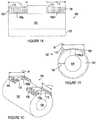
- Figures 1A-1Cillustrate an exemplary casing assembly 100, according to one or more embodiments disclosed.
- Figure 1Aprovides a side view
- Figure 1Ban end view
- Figure 1Cdepicts an isometric view of the casing assembly 100.
- the casing assembly 100can be implemented as a compressor casing, either for a positive displacement compressor or a dynamic compressor.
- the casing assembly 100can be used in a centrifugal compressor application for operation in the oil and gas industry ( i.e ., upstream, midstream, and downstream).
- the casing assembly 100includes a substantially-cylindrical barrel 102 that defines an axially-extending bore 104.
- the bore 104is concentrically-disposed within the barrel 102 and extends axially from one end of the barrel 102 to the other.
- the barrel 102may be forged as a single-piece, but may also be assembled from two or more segments to form a complete casing barrel 102. In other embodiments, however, the barrel 102 may be manufactured by other processes known in the art, such as machining from a single piece of material.
- the barrel 102may be made of a non-corrosive material, such as stainless steel or other variations of carbon steels that are overlaid resistant to corrosive environments. It will be appreciated, however, that the barrel 102 may be made out of any material known in the art that exhibits corrosion-resistive and pressure-containing properties.
- Pressures in compressor applicationscan range anywhere from about 1,200psi (8.3 MPa) to about 15,000psi (103.4 MPa).
- the minimum thickness of the barrel 102is determined in order to manufacture a barrel 102 that meets and/or exceeds the pressure requirements.
- the required thickness of the barrel 102 to withstand pressures for an exemplary applicationis illustrated by arrow 105.
- the barrel 102may be manufactured to an overall thickness slightly larger than the required thickness 105.
- the barrel 102may also define an inlet conduit 106a and a discharge conduit 106b for the receipt and discharge of process gases, respectively.
- the barrel 102may define more than two conduits 106a,b without departing from the scope of the disclosure.
- the conduits 106a,bmay be directly forged into the casing assembly 100 at predetermined locations along the axial length of the casing assembly 100 and subsequently machined to tolerances. In other embodiments, however, the conduits 106a,b may be machined into the casing assembly 100 at the predetermined locations.
- the casing assembly 100may further include a weld filler 108 applied to the outside surface of the barrel 102 at or near the location of each conduit 106a,b.
- the weld filler 108may generally be applied to add material to the outside surface of the barrel 102.
- the weld filler 108is applied in multiple layers about ( e.g ., around) each conduit 106a,b.
- the weld filler 108is applied proximate each conduit 106a,b ( i.e ., the weld filler may or may not extend completely around each conduit 106a,b).
- the weld filler 108may provide at least a portion of a mounting surface 110.
- the length L and width W of the weld filler 108may be determined from the known general size and/or dimensions of any coupling component (e.g ., the inlet flange 202a and discharge flange 202b shown in Figures 2A and 2B ) that will eventually be coupled to the barrel 102.
- the weld filler 108may be applied in a large enough area about each conduit 106a,b so as to accommodate the corresponding size of each coupling component to be attached thereto.
- an additional amount of weld filler 108is applied to the length L and width W to account for dimensional variations and also to boost the structural integrity of the mounting surface 110.
- the weld filler 108may be applied in multiple layers to the surface of the barrel 102 using a variety of welding methods.
- weld methodsthat may be used include, but are not limited to, shielded metal arc welding, gas tungsten arc welding (e.g ., tungsten inert gas (TIG) welding), flux-cored arc welding, submerged arc welding, strip submerged arc welding, strip electroslag welding, and gas metal arc welding (i.e ., MIG or MAG welding).
- the weld filler 108may be applied to the surface of the barrel 102 using laser cladding techniques.
- the barrel 102may be locally preheated (i.e ., around the area of the conduits 106a,b) to a temperature of about 200°F (93.3°C) to about 500°F (260.0°C). In other embodiments, the entire barrel 102 may be preheated.
- the welding processmay employ multi-pass overlay welding techniques, such as spiral or step-over type techniques, that result in melting approximately 1 ⁇ 2 the previous weld bead. Until the welding process is completed, a minimum interpass temperature of about 200°F (93.3°C) to about 500°F (260.0°C) may be maintained in the region adjacent the conduits 106a,b. In one embodiment, the interpass temperature may be maintained lower than 800°F (426.7°C) during the welding process.
- the entire casing assembly 100may undergo at least one thermal stress cycle.
- the thermal stress cyclemay be configured to reduce the residual stresses generated due to the welding process, but it may also serve to minimize the hardness of the weld filler 108 and adjacent heat affected zone ("HAZ"), thereby increasing the overall ductility of the material.
- the thermal stress cyclemay include placing the entire casing assembly 100 in an atmosphere-controlled furnace at a temperature ranging from about 1000°F (537.8°C) to about 1200°F (648.9°C) ( ⁇ 25°F, i.e ., about 975°F (523.9°C) to about 1225°F (662.8°C)) for at least one hour per one inch (2.54 cm) of weld thickness.
- the thermal stress cyclecan be undertaken locally by heating only the weld filler 108 and HAZ from about 1000°F (537.8°C) to about 1200°F (648.9°C) ( ⁇ 25°F, i.e ., about 975°F (523.9°C) to about 1225°F (662.8°C)) for at least one hour per one inch (2.54 cm) of weld thickness.
- Thermal stress cyclesmay prove advantageous in increasing the ductility of the casing assembly 100, thereby providing for longer useful life.
- the weld filler 108may be further prepared for receipt of the inlet and discharge flanges 202a,b.
- the weld filler 108 and a portion of the underlying barrel 102may be milled or otherwise machined to create or otherwise form the mounting surface 110.
- the mounting surface 110may be a smooth and flat surface, thereby facilitating a fluid tight seal against the barrel 102.
- the conduits 106a,bmay be centrally-defined within each mounting surface 110.
- FIGS. 2A and 2Bdepicted are side and end views, respectively, of the casing assembly 100 as coupled or otherwise attached to an exemplary inlet flange 202a and exemplary discharge flange 202b.
- the flanges 202a,bmay be coupled or otherwise attached to an inlet pipeline 203a and discharge pipeline 203b, respectively.
- the flanges 202a,bmay be secured to the mounting surfaces 110 of the barrel 102 by a series of threaded bolts 204 inserted into a series of corresponding threaded bores 206 defined within both the weld filler 108 and the barrel 102.
- the flanges 202a,bplace the respective pipelines 203a,b in direct fluid communication with the corresponding conduits 106a,b. Accordingly, the mounting surfaces 110 may completely take the place of inlet and discharge nozzles as commonly used in compressor applications.
- process gasesdo not come into contact with the weld filler 108 but solely communicate with the pure base metal of the barrel 102 and the flanges 202a,b. Consequently, stringent NACE guidelines prescribing minimum hardness and corrosive-resistant standards for welded surfaces coming into contact with process gases may be entirely bypassed. Furthermore, since the flanges 202a,b are coupled to the barrel 102 via the mounting surface 110 created partially by the weld filler 108, an oversized barrel encompassing a significant amount of unneeded material is not required as in prior structural flats applications.
- the method 300may include locating or creating inlet/discharge conduits on a barrel, as at 302.
- a weld fillermay be applied to the outside surface of the barrel adjacent the conduits, as at 304.
- the particular dimensions of the weld fillermay be tied or otherwise subject to the dimensions of the inlet/discharge flanges that will be subsequently coupled to the barrel.
- weld fillerwill not be exposed to process gases in the casing assembly, several welding methods may be employed to apply the weld filler, including, but not limited to, shielded metal arc welding, TIG welding, flux-cored arc welding, submerged arc welding, strip submerged arc welding, strip electroslag welding, and MIG welding.
- the weld filler materialis applied in multiple layers across the outside surface of the barrel in order to build up the barrel surface for milling.
- the method 300may further include heat treating the weld filler and accompanying HAZ, as at 306. Such heat treatments, as described herein, may reduce residual stresses in the weld material, but also make the weld filler more ductile. In at least one embodiment, the thermal stress cycle can be imposed on the whole casing assembly, and not just the weld filler and HAZ. The weld filler may then be milled to create a mounting surface, as at 308.
- Milling the weld fillermay, in at least one embodiment, also include milling at least a portion of the barrel to create a smooth and flat mounting plane where the inlet/discharge flanges may be arranged to form a fluid tight seal against the barrel and fluidly communicate with the inlet/discharge conduits, respectively.
- inlet and discharge flangesmay be coupled thereto, as at 310.
- the barrel 102may provide the equivalent functionality of a larger barrel 102 but at a lower cost and without diminishing the overall strength of the system 100.
- welding a filler metal to the outside surface of the barrel 102 and milling a flat surface therefromis not only cost-effective, but also provides a strong and thermally-protected metal bond.
- implementing welded flats to the outside surface of the barrel 102avoids having to comply with NACE requirements, which can be an expensive and time-consuming process.
- the term "about” used in conjunction with a numeralrefers to a range of that numeral starting from below the absolute of the numeral to above the absolute of the numeral, inclusive.
- the term “about 200°F (93.3°C)”may refer to a range of 180°F (82.2°C) to 220°F (104.4°C).
Landscapes
- Engineering & Computer Science (AREA)
- Mechanical Engineering (AREA)
- Physics & Mathematics (AREA)
- Chemical & Material Sciences (AREA)
- General Engineering & Computer Science (AREA)
- Optics & Photonics (AREA)
- Plasma & Fusion (AREA)
- Crystallography & Structural Chemistry (AREA)
- Metallurgy (AREA)
- Organic Chemistry (AREA)
- Materials Engineering (AREA)
- Thermal Sciences (AREA)
- Structures Of Non-Positive Displacement Pumps (AREA)
- Arc Welding In General (AREA)
Description
- The present application relates to a compressor casing assembly according to the preamble of claim 1, and a method of manufacturing a compressor casing assembly.
- To ensure long-term operation, compressor casings must be designed to withstand extreme pressures and potentially corrosive environments, especially in the oil and gas industry. A typical compressor consists of a casing, usually in the shape of a cylindrical body, which is sealed at its ends and houses the operating components of the machine. The compressor will usually have an inlet nozzle and a discharge nozzle welded to the outside surface of the casing where the gas or fluid is either introduced to or discharged from the casing, respectively.
- For commercial consumption, compressor casings must also meet industry standards and regulations. For instance, certain compressor casings are required to meet safety regulations and standards stipulated by the National Association of Corrosion Engineers ("NACE"). At least one NACE standard prescribes minimum hardness requirements for any compressor base metal, weld metal, and heat affected zone that may come in contact with corrosive process gases or fluids during compressor operations. For compressors having inlet and discharge nozzles welded to the outside surface of the casing, this standard can be extremely difficult to satisfy. For example, special base metal and weld metals are often required during manufacturing, and such metals can restrict the casing chemistry needed to achieve standard requirements after welding. Moreover, because of the NACE requirements, there are only a limited number of weld wires that can effectively be employed.
- As an alternative to complying with the stringent NACE requirements, some have milled structural flats on the compressor that allow inlet and discharge flanges to be coupled directly to the casing, instead of to the welded-on inlet and discharge nozzles. By so doing, process gases and fluids only come into contact with the pure base metal of the casing and flanges and NACE requirements are met via the base metal itself. To use structural flats, however, a larger diameter casing than what is actually needed is required so that a portion of the casing can be milled away and removed to provide a mounting surface for the flanges. A larger diameter casing, unfortunately, can add significant expense to the overall compressor system.
- What is needed, therefore, is a compressor casing that overcomes the disadvantages of prior applications as outlined above.
US 6 506 017 discloses a compressor casing assembly according to the preamble of claim 1 and a method of manufacturing a compressor casing assembly according to the preamble of claim 8. - The disclosure provides a compressor casing assembly according to claim 1. The casing assembly includes a barrel defining a centrally-disposed bore, and a conduit defined in the barrel and in fluid communication with the bore. The casing assembly further includes a mounting surface formed around a perimeter of the conduit on an outside surface of the barrel, the mounting surface comprising multiple built-up layers of a weld material.
- The disclosure further provides a method of making a compressor casing assembly according to claim 8. The method includes applying multiple layers of a weld filler material to an outside surface of a casing about a conduit defined therein, and heat treating multiple layers of weld filler material to reduce residual stresses. The method further includes milling the multiple layers of weld filler material and a section of the casing to create a substantially planar mounting surface. A flange may then be coupled to the mounting surface to form a gas tight seal therebetween.
- Embodiments of the disclosure may further provide another casing assembly for a compressor: The casing assembly may include a barrel defining a centrally-disposed bore and an outside surface, and a conduit defined in the barrel and in fluid communication with the bore. The casing assembly may further include a mounting surface formed on the outside surface of the barrel, the mounting surface comprising multiple built-up layers of a weld material applied to opposing sides of the conduit about a circumference of the outside surface of the barrel.
- The present disclosure is best understood from the following detailed description when read with the accompanying Figures. It is emphasized that, in accordance with the standard practice in the industry, various features are not drawn to scale. In fact, the dimensions of the various features may be arbitrarily increased or reduced for clarity of discussion.
Figure 1A illustrates a side view of an exemplary casing assembly, according to one or more embodiments of the present disclosure.Figure 1B illustrates an end view of the exemplary casing assembly ofFigure 1A , according to one or more embodiments of the present disclosure.Figure 1C illustrates an isometric view of the exemplary casing assembly ofFigure 1A , according to one or more embodiments of the present disclosure.Figure 2A illustrates a side view of the exemplary casing assembly ofFigure 1A as attached to inlet/discharge flanges, according to one or more embodiments of the present disclosure.Figure 2B illustrates an end view of the exemplary casing assembly ofFigure 2A , according to one or more embodiments of the present disclosure.Figure 3 illustrates an exemplary flowchart method of making a casing assembly, according to one or more embodiments of the present disclosure.- It is to be understood that the following disclosure describes several exemplary embodiments for implementing different features, structures, or functions of the invention. Additionally, the present disclosure may repeat reference numerals and/or letters in the various exemplary embodiments and across the Figures provided herein. This repetition is for the purpose of simplicity and clarity and does not in itself dictate a relationship between the various exemplary embodiments and/or configurations discussed in the various Figures. Moreover, the formation of a first feature over or on a second feature in the description that follows may include embodiments in which the first and second features are formed in direct contact, and may also include embodiments in which additional features may be formed interposing the first and second features, such that the first and second features may not be in direct contact.
- Additionally all numerical values in this disclosure may be exact or approximate values unless otherwise specifically stated.
Figures 1A-1C illustrate anexemplary casing assembly 100, according to one or more embodiments disclosed.Figure 1A provides a side view,Figure 1B an end view, andFigure 1C depicts an isometric view of thecasing assembly 100. In at least one embodiment, thecasing assembly 100 can be implemented as a compressor casing, either for a positive displacement compressor or a dynamic compressor. In one or more embodiments, thecasing assembly 100 can be used in a centrifugal compressor application for operation in the oil and gas industry (i.e., upstream, midstream, and downstream).- The
casing assembly 100 includes a substantially-cylindrical barrel 102 that defines an axially-extendingbore 104. Thebore 104 is concentrically-disposed within thebarrel 102 and extends axially from one end of thebarrel 102 to the other. In an exemplary embodiment, thebarrel 102 may be forged as a single-piece, but may also be assembled from two or more segments to form acomplete casing barrel 102. In other embodiments, however, thebarrel 102 may be manufactured by other processes known in the art, such as machining from a single piece of material. Since the process gas being compressed in thecasing assembly 100 may be potentially corrosive, thebarrel 102 may be made of a non-corrosive material, such as stainless steel or other variations of carbon steels that are overlaid resistant to corrosive environments. It will be appreciated, however, that thebarrel 102 may be made out of any material known in the art that exhibits corrosion-resistive and pressure-containing properties. - Pressures in compressor applications can range anywhere from about 1,200psi (8.3 MPa) to about 15,000psi (103.4 MPa). To withstand such extreme pressures, the minimum thickness of the
barrel 102 is determined in order to manufacture abarrel 102 that meets and/or exceeds the pressure requirements. Referring toFigure 1B , the required thickness of thebarrel 102 to withstand pressures for an exemplary application is illustrated byarrow 105. For reasons that will be described below, thebarrel 102 may be manufactured to an overall thickness slightly larger than the requiredthickness 105. - The
barrel 102 may also define aninlet conduit 106a and adischarge conduit 106b for the receipt and discharge of process gases, respectively. As can be appreciated, thebarrel 102 may define more than twoconduits 106a,b without departing from the scope of the disclosure. In one or more embodiments, theconduits 106a,b may be directly forged into thecasing assembly 100 at predetermined locations along the axial length of thecasing assembly 100 and subsequently machined to tolerances. In other embodiments, however, theconduits 106a,b may be machined into thecasing assembly 100 at the predetermined locations. - The
casing assembly 100 may further include aweld filler 108 applied to the outside surface of thebarrel 102 at or near the location of eachconduit 106a,b. Theweld filler 108 may generally be applied to add material to the outside surface of thebarrel 102. In one or more embodiments, theweld filler 108 is applied in multiple layers about (e.g., around) eachconduit 106a,b. In other embodiments, theweld filler 108 is applied proximate eachconduit 106a,b (i.e., the weld filler may or may not extend completely around eachconduit 106a,b). - The
weld filler 108 may provide at least a portion of a mountingsurface 110. The length L and width W of theweld filler 108 may be determined from the known general size and/or dimensions of any coupling component (e.g., theinlet flange 202a anddischarge flange 202b shown inFigures 2A and 2B ) that will eventually be coupled to thebarrel 102. In other words, theweld filler 108 may be applied in a large enough area about eachconduit 106a,b so as to accommodate the corresponding size of each coupling component to be attached thereto. In one embodiment, an additional amount ofweld filler 108 is applied to the length L and width W to account for dimensional variations and also to boost the structural integrity of the mountingsurface 110. - The
weld filler 108 may be applied in multiple layers to the surface of thebarrel 102 using a variety of welding methods. For example, weld methods that may be used include, but are not limited to, shielded metal arc welding, gas tungsten arc welding (e.g., tungsten inert gas (TIG) welding), flux-cored arc welding, submerged arc welding, strip submerged arc welding, strip electroslag welding, and gas metal arc welding (i.e., MIG or MAG welding). In other embodiments, theweld filler 108 may be applied to the surface of thebarrel 102 using laser cladding techniques. - To enhance the quality of the weld, the
barrel 102 may be locally preheated (i.e., around the area of theconduits 106a,b) to a temperature of about 200°F (93.3°C) to about 500°F (260.0°C). In other embodiments, theentire barrel 102 may be preheated. In at least one embodiment, the welding process may employ multi-pass overlay welding techniques, such as spiral or step-over type techniques, that result in melting approximately ½ the previous weld bead. Until the welding process is completed, a minimum interpass temperature of about 200°F (93.3°C) to about 500°F (260.0°C) may be maintained in the region adjacent theconduits 106a,b. In one embodiment, the interpass temperature may be maintained lower than 800°F (426.7°C) during the welding process. - Subsequent to the application of the
weld filler 108 to the approximate desired length L and width W adjacent theconduits 106a,b, theentire casing assembly 100 may undergo at least one thermal stress cycle. The thermal stress cycle may be configured to reduce the residual stresses generated due to the welding process, but it may also serve to minimize the hardness of theweld filler 108 and adjacent heat affected zone ("HAZ"), thereby increasing the overall ductility of the material. In one or more embodiments, the thermal stress cycle may include placing theentire casing assembly 100 in an atmosphere-controlled furnace at a temperature ranging from about 1000°F (537.8°C) to about 1200°F (648.9°C) (± 25°F,i.e., about 975°F (523.9°C) to about 1225°F (662.8°C)) for at least one hour per one inch (2.54 cm) of weld thickness. In other embodiments, the thermal stress cycle can be undertaken locally by heating only theweld filler 108 and HAZ from about 1000°F (537.8°C) to about 1200°F (648.9°C) (± 25°F,i.e., about 975°F (523.9°C) to about 1225°F (662.8°C)) for at least one hour per one inch (2.54 cm) of weld thickness. Thermal stress cycles may prove advantageous in increasing the ductility of thecasing assembly 100, thereby providing for longer useful life. - Once the
weld filler 108 and HAZ have been properly treated via one or more thermal stress cycles, theweld filler 108 may be further prepared for receipt of the inlet and dischargeflanges 202a,b. Theweld filler 108 and a portion of theunderlying barrel 102 may be milled or otherwise machined to create or otherwise form the mountingsurface 110. Once milled, the mountingsurface 110 may be a smooth and flat surface, thereby facilitating a fluid tight seal against thebarrel 102. As illustrated inFigure 1C , theconduits 106a,b may be centrally-defined within each mountingsurface 110. - Referring now to
Figures 2A and 2B , with continuing reference toFigures 1A-1C , depicted are side and end views, respectively, of thecasing assembly 100 as coupled or otherwise attached to anexemplary inlet flange 202a andexemplary discharge flange 202b. As illustrated, theflanges 202a,b may be coupled or otherwise attached to aninlet pipeline 203a anddischarge pipeline 203b, respectively. In one or more embodiments, theflanges 202a,b may be secured to the mountingsurfaces 110 of thebarrel 102 by a series of threadedbolts 204 inserted into a series of corresponding threadedbores 206 defined within both theweld filler 108 and thebarrel 102. Once coupled to thebarrel 102, theflanges 202a,b place therespective pipelines 203a,b in direct fluid communication with the correspondingconduits 106a,b. Accordingly, the mountingsurfaces 110 may completely take the place of inlet and discharge nozzles as commonly used in compressor applications. - During operation of the
casing assembly 100, process gases do not come into contact with theweld filler 108 but solely communicate with the pure base metal of thebarrel 102 and theflanges 202a,b. Consequently, stringent NACE guidelines prescribing minimum hardness and corrosive-resistant standards for welded surfaces coming into contact with process gases may be entirely bypassed. Furthermore, since theflanges 202a,b are coupled to thebarrel 102 via the mountingsurface 110 created partially by theweld filler 108, an oversized barrel encompassing a significant amount of unneeded material is not required as in prior structural flats applications. - Referring now to
Figure 3 , amethod 300 of constructing anexemplary casing assembly 100 as described herein is depicted. In one or more embodiments, themethod 300 may include locating or creating inlet/discharge conduits on a barrel, as at 302. A weld filler may be applied to the outside surface of the barrel adjacent the conduits, as at 304. The particular dimensions of the weld filler may be tied or otherwise subject to the dimensions of the inlet/discharge flanges that will be subsequently coupled to the barrel. Furthermore, since the weld filler will not be exposed to process gases in the casing assembly, several welding methods may be employed to apply the weld filler, including, but not limited to, shielded metal arc welding, TIG welding, flux-cored arc welding, submerged arc welding, strip submerged arc welding, strip electroslag welding, and MIG welding. In one or more embodiments, the weld filler material is applied in multiple layers across the outside surface of the barrel in order to build up the barrel surface for milling. - The
method 300 may further include heat treating the weld filler and accompanying HAZ, as at 306. Such heat treatments, as described herein, may reduce residual stresses in the weld material, but also make the weld filler more ductile. In at least one embodiment, the thermal stress cycle can be imposed on the whole casing assembly, and not just the weld filler and HAZ. The weld filler may then be milled to create a mounting surface, as at 308. Milling the weld filler may, in at least one embodiment, also include milling at least a portion of the barrel to create a smooth and flat mounting plane where the inlet/discharge flanges may be arranged to form a fluid tight seal against the barrel and fluidly communicate with the inlet/discharge conduits, respectively. Once the mounting surface is prepared, inlet and discharge flanges may be coupled thereto, as at 310. - As can be appreciated, there are several advantages to the embodiments disclosed herein. For instance, the
barrel 102 may provide the equivalent functionality of alarger barrel 102 but at a lower cost and without diminishing the overall strength of thesystem 100. Moreover, welding a filler metal to the outside surface of thebarrel 102 and milling a flat surface therefrom is not only cost-effective, but also provides a strong and thermally-protected metal bond. Lastly, implementing welded flats to the outside surface of thebarrel 102 avoids having to comply with NACE requirements, which can be an expensive and time-consuming process. - As used herein, the term "about" used in conjunction with a numeral refers to a range of that numeral starting from below the absolute of the numeral to above the absolute of the numeral, inclusive. For example, the term "about 200°F (93.3°C)" may refer to a range of 180°F (82.2°C) to 220°F (104.4°C).
Claims (15)
- A compressor casing assembly (100), comprising:a barrel (102) defining a bore (104) concentrically-disposed within the barrel;a conduit (106a,b) defined in the barrel (102) and in fluid communication with the bore (104); anda mounting surface (110) formed around a perimeter of the conduit (106a,b) on an outside surface of the barrel (102),characterized in that at least a portion of the mounting surface (110) is formed from multiple built-up layers of a weld material (108) and configured to be substantially planar with a remaining portion of the mounting surface (110).
- The casing assembly of claim 1, wherein the remaining portion of the mounting surface (110) further includes a section of the outside surface of the barrel (102).
- The casing assembly of claim 1, wherein the mounting surface (10) comprises a milled surface.
- The casing assembly of claim 3, further comprising a flange connection (202a,b) formed into the mounting surface (110).
- The casing assembly of claim 1, wherein the multiple built-up layers of the weld material (108) are applied to the outside surface of the barrel by shielded metal arc welding, TIG welding, flux-cored arc welding, submerged arc welding, strip submerged arc welding, strip electroslag welding, or MIG welding.
- The casing assembly of claim 1, wherein the weld material is isolated from a process gas flowing within the compressor during compressor operation.
- The casing assembly of claim 1, wherein the conduit (106a,b) comprises a first conduit (106a) for the inlet of a process gas, the barrel (102) further defining a second conduit (106b) in fluid communication with the bore (104) for the discharge of the process gas.
- A method of manufacturing a compressor casing assembly,characterized in that it comprises:applying multiple layers of a weld material (108) to an outside surface of a casing (100) around a portion of a perimeter of a conduit defined therein;heat treating the weld material to reduce residual stresses;milling the weld material and a section of the casing to create a planar mounting surface (110); andforming one or more conduits (106a,b) in the planar mounting surface (110) to couple a flange thereto and form a fluid tight seal therebetween.
- The method of claim 8, further comprising preheating an area adjacent the conduit (106a,b) where the weld material (108) is to be applied.
- The method of claim 9, wherein the area adjacent the conduit (106a,b) is preheated to a temperature of between about 93.3°C and about 260.0°C.
- The method of claim 8, wherein applying the multiple layers of weld material to the outside surface of the casing (100) comprises welding the weld material to the casing (100).
- The method of claim 11, wherein the multiple layers of weld material (108) are welded to the casing (100) using a multi-pass overlay welding technique configured to melt about half of a previous weld bead.
- The method of claim 8, further comprising applying the weld material to the outside surface of the casing (100) to a length and width corresponding to a structural dimension of the flange (202a,b).
- The method of claim 8, wherein heat treating the weld material further comprises heat treating a heat affected zone adjacent the weld material (108).
- The method of claim 14, wherein heat treating comprises increasing the temperature of the weld material and heat affected zone to a temperature of from about 537.8°C to about 648.9°C.
Applications Claiming Priority (3)
| Application Number | Priority Date | Filing Date | Title |
|---|---|---|---|
| US30615410P | 2010-02-19 | 2010-02-19 | |
| PCT/US2011/022716WO2011102945A2 (en) | 2010-02-19 | 2011-01-27 | Welded structural flats on cases to eliminate nozzles |
| US13/014,966US8672621B2 (en) | 2010-02-19 | 2011-01-27 | Welded structural flats on cases to eliminate nozzles |
Publications (3)
| Publication Number | Publication Date |
|---|---|
| EP2536951A2 EP2536951A2 (en) | 2012-12-26 |
| EP2536951A4 EP2536951A4 (en) | 2013-07-03 |
| EP2536951B1true EP2536951B1 (en) | 2016-05-18 |
Family
ID=44476622
Family Applications (1)
| Application Number | Title | Priority Date | Filing Date |
|---|---|---|---|
| EP11745025.4ANot-in-forceEP2536951B1 (en) | 2010-02-19 | 2011-01-27 | Compressor casing assembly and manufacturing method thereof |
Country Status (4)
| Country | Link |
|---|---|
| US (1) | US8672621B2 (en) |
| EP (1) | EP2536951B1 (en) |
| BR (1) | BR112012020843A8 (en) |
| WO (1) | WO2011102945A2 (en) |
Cited By (2)
| Publication number | Priority date | Publication date | Assignee | Title |
|---|---|---|---|---|
| CN107825067A (en)* | 2017-12-01 | 2018-03-23 | 无锡锡压压缩机有限公司 | A kind of manufacturing processing technic of helical-lobe compressor housing |
| WO2025159749A1 (en)* | 2024-01-25 | 2025-07-31 | Siemens Energy Global GmbH & Co. KG | System and process for electroslag additive manufacturing |
Families Citing this family (2)
| Publication number | Priority date | Publication date | Assignee | Title |
|---|---|---|---|---|
| CN102500868B (en)* | 2011-11-01 | 2014-07-09 | 上海锅炉厂有限公司 | Process for welding lugs on central cylinder body of horizontal preheater |
| CN112355510B (en)* | 2020-11-12 | 2022-03-15 | 浙江创新激光设备有限公司 | Compressor welding device |
Family Cites Families (46)
| Publication number | Priority date | Publication date | Assignee | Title |
|---|---|---|---|---|
| GB609926A (en)* | 1946-03-25 | 1948-10-08 | Adrian Albert Lombard | Improvements in or relating to internal-combustion turbines |
| US2850876A (en)* | 1948-08-06 | 1958-09-09 | Garrett Corp | Gas turbine compressor and power take-off drive |
| US3283723A (en)* | 1965-07-09 | 1966-11-08 | Germane Corp | Rotary fluid pressure devices |
| US3420434A (en)* | 1966-12-30 | 1969-01-07 | Judson S Swearingen | Rotary compressors and systems employing same using compressor gas as seal gas |
| US3696637A (en)* | 1968-08-15 | 1972-10-10 | Air Prod & Chem | Method and apparatus for producing refrigeration |
| US3628627A (en)* | 1970-10-02 | 1971-12-21 | Vacu Blast Corp | Silencer for air-blasting gun |
| US4198740A (en)* | 1978-07-24 | 1980-04-22 | The United States Of America As Represented By The United States Department Of Energy | Method for forming or bonding a liner |
| DE2940029C2 (en)* | 1979-10-03 | 1984-03-29 | Klein, Schanzlin & Becker Ag, 6710 Frankenthal | Centrifugal pump housing |
| US4432824A (en)* | 1980-07-31 | 1984-02-21 | Raychem Corporation | Method for internal pipe protection |
| US4399651A (en)* | 1981-05-28 | 1983-08-23 | Elliott Turbomachinery Co., Inc. | Method for starting an FCC power recovery string |
| US4477223A (en)* | 1982-06-11 | 1984-10-16 | Texas Turbine, Inc. | Sealing system for a turboexpander compressor |
| US4524996A (en)* | 1982-10-15 | 1985-06-25 | Allegheny Ludlum Steel Corporation | Corrosion-resistant tube assembly |
| US4834622A (en)* | 1983-06-15 | 1989-05-30 | Sundstrand Corporation | Gas turbine engine/load compressor power plants |
| US4484689A (en)* | 1983-08-08 | 1984-11-27 | Fuchs Jr Francis J | Axially segmented pressure vessel |
| US4545101A (en)* | 1984-02-01 | 1985-10-08 | Hilts John R | Method for preventing cylinder head warpage, and over-heating of internal combustion engines |
| US4759178A (en)* | 1987-03-17 | 1988-07-26 | Williams International Corporation | Aircraft auxiliary power unit |
| US4972880A (en)* | 1987-06-15 | 1990-11-27 | Insta-Pipe Research Limited Partnership | Pipe liner |
| DE3800913A1 (en)* | 1988-01-14 | 1989-08-03 | Emitec Emissionstechnologie | MULTI-LAYER DRIVE SHAFT |
| US4881880A (en)* | 1988-04-19 | 1989-11-21 | Parker Hannifin Corporation | Drain for internal gear hydraulic device |
| US4870732A (en)* | 1988-04-25 | 1989-10-03 | Harris Graphics Corporation | Stainless steel weld clad cylinder roller interconnected by a groove and gap also weld covered by stainless steel |
| US4826071A (en)* | 1988-04-25 | 1989-05-02 | Harris Graphics | Stainless steel weld clad cylinder interconnected by a groove and gap also weld covered by stainless steel |
| US4903888A (en)* | 1988-05-05 | 1990-02-27 | Westinghouse Electric Corp. | Turbine system having more failure resistant rotors and repair welding of low alloy ferrous turbine components by controlled weld build-up |
| US4959523A (en)* | 1988-11-18 | 1990-09-25 | Hydro-Quebec | Method and apparatus for automatically sensing the configuration of a surface area and effecting a work function thereon |
| US4893388A (en)* | 1988-12-08 | 1990-01-16 | Westinghouse Electric Corp. | Method of modifying turbine rotor discs |
| US5085363A (en)* | 1990-11-01 | 1992-02-04 | Westinghouse Electric Corp. | Method of weld repairing of a section of a metallic cylindrical member |
| US5248239A (en)* | 1992-03-19 | 1993-09-28 | Acd, Inc. | Thrust control system for fluid handling rotary apparatus |
| US5605361A (en)* | 1994-05-06 | 1997-02-25 | Entergy Operations, Inc. | Replacement nozzle for pressure vessels and method of a attaching same |
| US6310414B1 (en)* | 1994-06-21 | 2001-10-30 | Rotoflow Corporation | Shaft bearing system |
| US5671532A (en)* | 1994-12-09 | 1997-09-30 | Ford Global Technologies, Inc. | Method of making an engine block using coated cylinder bore liners |
| DE19607521C1 (en)* | 1996-02-28 | 1997-04-10 | Juergen Dipl Ing Guido | High-pressure fuel pipe, for diesel engine with common-rail system |
| JP3882964B2 (en)* | 1996-11-30 | 2007-02-21 | 臼井国際産業株式会社 | Connection structure of branch connection in common rail |
| US6018941A (en)* | 1997-09-19 | 2000-02-01 | Lamar Technologies Corporation | Electric starter system for turbine aircraft engines |
| US6154946A (en)* | 1998-01-05 | 2000-12-05 | Elmhurst Research, Inc. | Method for the manufacture of very high pressure vessels to survive high cycle fatigue loading |
| US6085545A (en)* | 1998-09-18 | 2000-07-11 | Johnston; Richard P. | Liquid natural gas system with an integrated engine, compressor and expander assembly |
| GB9913072D0 (en)* | 1999-06-04 | 1999-08-04 | Cryostar France Sa | Machine |
| US20030024629A1 (en)* | 2000-02-15 | 2003-02-06 | Nigel Wright | Method of lining pipes |
| IT1317651B1 (en)* | 2000-05-19 | 2003-07-15 | Nuovo Pignone Spa | CASE FOR CENTRIFUGAL COMPRESSORS AND PROCEDURE FOR SUAREALIZATION |
| US6955288B2 (en)* | 2001-01-31 | 2005-10-18 | E. I. Du Pont De Nemours And Company | Metallurgically bonded layered article having a curved surface |
| US6581409B2 (en)* | 2001-05-04 | 2003-06-24 | Bechtel Bwxt Idaho, Llc | Apparatus for the liquefaction of natural gas and methods related to same |
| US6826909B2 (en)* | 2001-11-08 | 2004-12-07 | Parker-Hannifin Corp. | Hydraulic gerotor motor with integral shuttle valve |
| EP1426607A1 (en) | 2002-12-06 | 2004-06-09 | Wärtsilä Schweiz AG | Pressure accumulator for a Common Rail system |
| CA2552722C (en)* | 2004-01-12 | 2012-08-07 | Shell Oil Company | Expandable connection |
| US7922065B2 (en)* | 2004-08-02 | 2011-04-12 | Ati Properties, Inc. | Corrosion resistant fluid conducting parts, methods of making corrosion resistant fluid conducting parts and equipment and parts replacement methods utilizing corrosion resistant fluid conducting parts |
| BE1017317A3 (en)* | 2006-06-01 | 2008-06-03 | Atlas Copco Airpower Nv | IMPROVED COMPRESSOR DEVICE. |
| WO2008024833A2 (en)* | 2006-08-22 | 2008-02-28 | David Vandor | A combined cycle system for gas turbines and reciprocating engines and a method for the use of air as working fluid in combined cycle power plants |
| US7821158B2 (en)* | 2008-05-27 | 2010-10-26 | Expansion Energy, Llc | System and method for liquid air production, power storage and power release |
- 2011
- 2011-01-27EPEP11745025.4Apatent/EP2536951B1/ennot_activeNot-in-force
- 2011-01-27WOPCT/US2011/022716patent/WO2011102945A2/enactiveApplication Filing
- 2011-01-27BRBR112012020843Apatent/BR112012020843A8/ennot_activeIP Right Cessation
- 2011-01-27USUS13/014,966patent/US8672621B2/ennot_activeExpired - Fee Related
Cited By (3)
| Publication number | Priority date | Publication date | Assignee | Title |
|---|---|---|---|---|
| CN107825067A (en)* | 2017-12-01 | 2018-03-23 | 无锡锡压压缩机有限公司 | A kind of manufacturing processing technic of helical-lobe compressor housing |
| CN107825067B (en)* | 2017-12-01 | 2019-09-20 | 无锡锡压压缩机有限公司 | Manufacturing and processing technology of a screw compressor shell |
| WO2025159749A1 (en)* | 2024-01-25 | 2025-07-31 | Siemens Energy Global GmbH & Co. KG | System and process for electroslag additive manufacturing |
Also Published As
| Publication number | Publication date |
|---|---|
| BR112012020843A8 (en) | 2018-06-19 |
| EP2536951A2 (en) | 2012-12-26 |
| US8672621B2 (en) | 2014-03-18 |
| US20110206505A1 (en) | 2011-08-25 |
| WO2011102945A3 (en) | 2011-12-22 |
| BR112012020843A2 (en) | 2017-08-29 |
| WO2011102945A2 (en) | 2011-08-25 |
| EP2536951A4 (en) | 2013-07-03 |
Similar Documents
| Publication | Publication Date | Title |
|---|---|---|
| Smith | Engineering with clad steel | |
| CN104197104B (en) | A kind of composite bimetal pipe and manufacturing process thereof | |
| EP2536951B1 (en) | Compressor casing assembly and manufacturing method thereof | |
| JP5006321B2 (en) | Method for making welded joints and method for repairing welded joints | |
| EP3224519B1 (en) | Fluid conduit element and method for producing the fluid conduit element | |
| US20140021244A1 (en) | Method of Manufacturing Coil Tubing Using Friction Stir Welding | |
| CN105108297B (en) | Integral composite flange and manufacturing method thereof | |
| CN107143703B (en) | A kind of mechanical composite tube and its manufacturing method of 825 nickel-base alloy of liner | |
| US20060186093A1 (en) | Method and Device for Producing Metal Composite Block Material | |
| JP2003136130A (en) | Manufacturing method of inner and outer surface submerged arc welded steel pipe with excellent seam weld toughness | |
| US12366420B2 (en) | Radiator and joint | |
| US20190022801A1 (en) | Method of making a corrosion resistant tube | |
| CN113785151A (en) | Metal pipe, in particular a pipe for transporting oil and gas, having a metal coating in the transition region | |
| CN203322515U (en) | Straight-slit compound steel pipe for conveying acid media | |
| US4209123A (en) | Prevention of sensitization of welded-heat affected zones in structures primarily made from austenitic stainless steel | |
| GB2625611A (en) | Radiator and joint | |
| CN204986222U (en) | Compound pipe fitting of bimetal build -up welding | |
| CN204893199U (en) | An integral composite flange | |
| CN103706926A (en) | Process for connecting lined stainless steel clad pipes with flanges | |
| CN116547438A (en) | Oil pipe fitting with fillet weld cladding and method for producing oil pipe fitting | |
| CN110465717B (en) | TIG arc brazing welding method | |
| JPH11290939A (en) | Manufacturing method of long double metal tube | |
| RU2686129C1 (en) | Method for connection of metal pipes with inner plastic lining | |
| UA77931C2 (en) | Method for repair of defect section of pipeline under pressure | |
| CN107191686B (en) | High-strength stainless steel composite steel pipe capable of being connected through end threads and manufacturing method thereof |
Legal Events
| Date | Code | Title | Description |
|---|---|---|---|
| PUAI | Public reference made under article 153(3) epc to a published international application that has entered the european phase | Free format text:ORIGINAL CODE: 0009012 | |
| 17P | Request for examination filed | Effective date:20120917 | |
| AK | Designated contracting states | Kind code of ref document:A2 Designated state(s):AL AT BE BG CH CY CZ DE DK EE ES FI FR GB GR HR HU IE IS IT LI LT LU LV MC MK MT NL NO PL PT RO RS SE SI SK SM TR | |
| DAX | Request for extension of the european patent (deleted) | ||
| A4 | Supplementary search report drawn up and despatched | Effective date:20130605 | |
| RIC1 | Information provided on ipc code assigned before grant | Ipc:F04B 39/00 20060101ALI20130530BHEP Ipc:B23K 31/02 20060101ALI20130530BHEP Ipc:F04B 39/12 20060101AFI20130530BHEP Ipc:F04C 29/12 20060101ALI20130530BHEP | |
| GRAP | Despatch of communication of intention to grant a patent | Free format text:ORIGINAL CODE: EPIDOSNIGR1 | |
| INTG | Intention to grant announced | Effective date:20151203 | |
| GRAS | Grant fee paid | Free format text:ORIGINAL CODE: EPIDOSNIGR3 | |
| GRAA | (expected) grant | Free format text:ORIGINAL CODE: 0009210 | |
| AK | Designated contracting states | Kind code of ref document:B1 Designated state(s):AL AT BE BG CH CY CZ DE DK EE ES FI FR GB GR HR HU IE IS IT LI LT LU LV MC MK MT NL NO PL PT RO RS SE SI SK SM TR | |
| REG | Reference to a national code | Ref country code:GB Ref legal event code:FG4D | |
| REG | Reference to a national code | Ref country code:CH Ref legal event code:EP | |
| REG | Reference to a national code | Ref country code:IE Ref legal event code:FG4D Ref country code:AT Ref legal event code:REF Ref document number:800739 Country of ref document:AT Kind code of ref document:T Effective date:20160615 | |
| REG | Reference to a national code | Ref country code:DE Ref legal event code:R096 Ref document number:602011026719 Country of ref document:DE | |
| REG | Reference to a national code | Ref country code:NL Ref legal event code:MP Effective date:20160518 | |
| REG | Reference to a national code | Ref country code:LT Ref legal event code:MG4D | |
| PG25 | Lapsed in a contracting state [announced via postgrant information from national office to epo] | Ref country code:LT Free format text:LAPSE BECAUSE OF FAILURE TO SUBMIT A TRANSLATION OF THE DESCRIPTION OR TO PAY THE FEE WITHIN THE PRESCRIBED TIME-LIMIT Effective date:20160518 Ref country code:NO Free format text:LAPSE BECAUSE OF FAILURE TO SUBMIT A TRANSLATION OF THE DESCRIPTION OR TO PAY THE FEE WITHIN THE PRESCRIBED TIME-LIMIT Effective date:20160818 Ref country code:FI Free format text:LAPSE BECAUSE OF FAILURE TO SUBMIT A TRANSLATION OF THE DESCRIPTION OR TO PAY THE FEE WITHIN THE PRESCRIBED TIME-LIMIT Effective date:20160518 Ref country code:NL Free format text:LAPSE BECAUSE OF FAILURE TO SUBMIT A TRANSLATION OF THE DESCRIPTION OR TO PAY THE FEE WITHIN THE PRESCRIBED TIME-LIMIT Effective date:20160518 | |
| REG | Reference to a national code | Ref country code:AT Ref legal event code:MK05 Ref document number:800739 Country of ref document:AT Kind code of ref document:T Effective date:20160518 | |
| PG25 | Lapsed in a contracting state [announced via postgrant information from national office to epo] | Ref country code:PT Free format text:LAPSE BECAUSE OF FAILURE TO SUBMIT A TRANSLATION OF THE DESCRIPTION OR TO PAY THE FEE WITHIN THE PRESCRIBED TIME-LIMIT Effective date:20160919 Ref country code:RS Free format text:LAPSE BECAUSE OF FAILURE TO SUBMIT A TRANSLATION OF THE DESCRIPTION OR TO PAY THE FEE WITHIN THE PRESCRIBED TIME-LIMIT Effective date:20160518 Ref country code:GR Free format text:LAPSE BECAUSE OF FAILURE TO SUBMIT A TRANSLATION OF THE DESCRIPTION OR TO PAY THE FEE WITHIN THE PRESCRIBED TIME-LIMIT Effective date:20160819 Ref country code:HR Free format text:LAPSE BECAUSE OF FAILURE TO SUBMIT A TRANSLATION OF THE DESCRIPTION OR TO PAY THE FEE WITHIN THE PRESCRIBED TIME-LIMIT Effective date:20160518 Ref country code:SE Free format text:LAPSE BECAUSE OF FAILURE TO SUBMIT A TRANSLATION OF THE DESCRIPTION OR TO PAY THE FEE WITHIN THE PRESCRIBED TIME-LIMIT Effective date:20160518 Ref country code:ES Free format text:LAPSE BECAUSE OF FAILURE TO SUBMIT A TRANSLATION OF THE DESCRIPTION OR TO PAY THE FEE WITHIN THE PRESCRIBED TIME-LIMIT Effective date:20160518 Ref country code:LV Free format text:LAPSE BECAUSE OF FAILURE TO SUBMIT A TRANSLATION OF THE DESCRIPTION OR TO PAY THE FEE WITHIN THE PRESCRIBED TIME-LIMIT Effective date:20160518 | |
| PG25 | Lapsed in a contracting state [announced via postgrant information from national office to epo] | Ref country code:IT Free format text:LAPSE BECAUSE OF FAILURE TO SUBMIT A TRANSLATION OF THE DESCRIPTION OR TO PAY THE FEE WITHIN THE PRESCRIBED TIME-LIMIT Effective date:20160518 | |
| PG25 | Lapsed in a contracting state [announced via postgrant information from national office to epo] | Ref country code:DK Free format text:LAPSE BECAUSE OF FAILURE TO SUBMIT A TRANSLATION OF THE DESCRIPTION OR TO PAY THE FEE WITHIN THE PRESCRIBED TIME-LIMIT Effective date:20160518 Ref country code:SK Free format text:LAPSE BECAUSE OF FAILURE TO SUBMIT A TRANSLATION OF THE DESCRIPTION OR TO PAY THE FEE WITHIN THE PRESCRIBED TIME-LIMIT Effective date:20160518 Ref country code:EE Free format text:LAPSE BECAUSE OF FAILURE TO SUBMIT A TRANSLATION OF THE DESCRIPTION OR TO PAY THE FEE WITHIN THE PRESCRIBED TIME-LIMIT Effective date:20160518 Ref country code:CZ Free format text:LAPSE BECAUSE OF FAILURE TO SUBMIT A TRANSLATION OF THE DESCRIPTION OR TO PAY THE FEE WITHIN THE PRESCRIBED TIME-LIMIT Effective date:20160518 Ref country code:RO Free format text:LAPSE BECAUSE OF FAILURE TO SUBMIT A TRANSLATION OF THE DESCRIPTION OR TO PAY THE FEE WITHIN THE PRESCRIBED TIME-LIMIT Effective date:20160518 | |
| REG | Reference to a national code | Ref country code:DE Ref legal event code:R097 Ref document number:602011026719 Country of ref document:DE | |
| PG25 | Lapsed in a contracting state [announced via postgrant information from national office to epo] | Ref country code:PL Free format text:LAPSE BECAUSE OF FAILURE TO SUBMIT A TRANSLATION OF THE DESCRIPTION OR TO PAY THE FEE WITHIN THE PRESCRIBED TIME-LIMIT Effective date:20160518 Ref country code:SM Free format text:LAPSE BECAUSE OF FAILURE TO SUBMIT A TRANSLATION OF THE DESCRIPTION OR TO PAY THE FEE WITHIN THE PRESCRIBED TIME-LIMIT Effective date:20160518 Ref country code:BE Free format text:LAPSE BECAUSE OF FAILURE TO SUBMIT A TRANSLATION OF THE DESCRIPTION OR TO PAY THE FEE WITHIN THE PRESCRIBED TIME-LIMIT Effective date:20160518 Ref country code:AT Free format text:LAPSE BECAUSE OF FAILURE TO SUBMIT A TRANSLATION OF THE DESCRIPTION OR TO PAY THE FEE WITHIN THE PRESCRIBED TIME-LIMIT Effective date:20160518 | |
| PLBE | No opposition filed within time limit | Free format text:ORIGINAL CODE: 0009261 | |
| STAA | Information on the status of an ep patent application or granted ep patent | Free format text:STATUS: NO OPPOSITION FILED WITHIN TIME LIMIT | |
| 26N | No opposition filed | Effective date:20170221 | |
| PG25 | Lapsed in a contracting state [announced via postgrant information from national office to epo] | Ref country code:SI Free format text:LAPSE BECAUSE OF FAILURE TO SUBMIT A TRANSLATION OF THE DESCRIPTION OR TO PAY THE FEE WITHIN THE PRESCRIBED TIME-LIMIT Effective date:20160518 | |
| REG | Reference to a national code | Ref country code:DE Ref legal event code:R119 Ref document number:602011026719 Country of ref document:DE | |
| REG | Reference to a national code | Ref country code:CH Ref legal event code:PL | |
| GBPC | Gb: european patent ceased through non-payment of renewal fee | Effective date:20170127 | |
| PG25 | Lapsed in a contracting state [announced via postgrant information from national office to epo] | Ref country code:MC Free format text:LAPSE BECAUSE OF FAILURE TO SUBMIT A TRANSLATION OF THE DESCRIPTION OR TO PAY THE FEE WITHIN THE PRESCRIBED TIME-LIMIT Effective date:20160518 | |
| REG | Reference to a national code | Ref country code:FR Ref legal event code:ST Effective date:20170929 | |
| PG25 | Lapsed in a contracting state [announced via postgrant information from national office to epo] | Ref country code:LI Free format text:LAPSE BECAUSE OF NON-PAYMENT OF DUE FEES Effective date:20170131 Ref country code:CH Free format text:LAPSE BECAUSE OF NON-PAYMENT OF DUE FEES Effective date:20170131 Ref country code:FR Free format text:LAPSE BECAUSE OF NON-PAYMENT OF DUE FEES Effective date:20170131 | |
| REG | Reference to a national code | Ref country code:IE Ref legal event code:MM4A | |
| PG25 | Lapsed in a contracting state [announced via postgrant information from national office to epo] | Ref country code:LU Free format text:LAPSE BECAUSE OF NON-PAYMENT OF DUE FEES Effective date:20170127 Ref country code:DE Free format text:LAPSE BECAUSE OF NON-PAYMENT OF DUE FEES Effective date:20170801 Ref country code:GB Free format text:LAPSE BECAUSE OF NON-PAYMENT OF DUE FEES Effective date:20170127 | |
| PG25 | Lapsed in a contracting state [announced via postgrant information from national office to epo] | Ref country code:IE Free format text:LAPSE BECAUSE OF NON-PAYMENT OF DUE FEES Effective date:20170127 | |
| PG25 | Lapsed in a contracting state [announced via postgrant information from national office to epo] | Ref country code:MT Free format text:LAPSE BECAUSE OF NON-PAYMENT OF DUE FEES Effective date:20170127 | |
| PG25 | Lapsed in a contracting state [announced via postgrant information from national office to epo] | Ref country code:AL Free format text:LAPSE BECAUSE OF FAILURE TO SUBMIT A TRANSLATION OF THE DESCRIPTION OR TO PAY THE FEE WITHIN THE PRESCRIBED TIME-LIMIT Effective date:20160518 | |
| PG25 | Lapsed in a contracting state [announced via postgrant information from national office to epo] | Ref country code:HU Free format text:LAPSE BECAUSE OF FAILURE TO SUBMIT A TRANSLATION OF THE DESCRIPTION OR TO PAY THE FEE WITHIN THE PRESCRIBED TIME-LIMIT; INVALID AB INITIO Effective date:20110127 | |
| PG25 | Lapsed in a contracting state [announced via postgrant information from national office to epo] | Ref country code:BG Free format text:LAPSE BECAUSE OF FAILURE TO SUBMIT A TRANSLATION OF THE DESCRIPTION OR TO PAY THE FEE WITHIN THE PRESCRIBED TIME-LIMIT Effective date:20160518 | |
| PG25 | Lapsed in a contracting state [announced via postgrant information from national office to epo] | Ref country code:CY Free format text:LAPSE BECAUSE OF NON-PAYMENT OF DUE FEES Effective date:20160518 | |
| PG25 | Lapsed in a contracting state [announced via postgrant information from national office to epo] | Ref country code:MK Free format text:LAPSE BECAUSE OF FAILURE TO SUBMIT A TRANSLATION OF THE DESCRIPTION OR TO PAY THE FEE WITHIN THE PRESCRIBED TIME-LIMIT Effective date:20160518 | |
| PG25 | Lapsed in a contracting state [announced via postgrant information from national office to epo] | Ref country code:TR Free format text:LAPSE BECAUSE OF FAILURE TO SUBMIT A TRANSLATION OF THE DESCRIPTION OR TO PAY THE FEE WITHIN THE PRESCRIBED TIME-LIMIT Effective date:20160518 | |
| PG25 | Lapsed in a contracting state [announced via postgrant information from national office to epo] | Ref country code:IS Free format text:LAPSE BECAUSE OF FAILURE TO SUBMIT A TRANSLATION OF THE DESCRIPTION OR TO PAY THE FEE WITHIN THE PRESCRIBED TIME-LIMIT Effective date:20160918 |