EP2534003B1 - Reading light for motor vehicles - Google Patents
Reading light for motor vehiclesDownload PDFInfo
- Publication number
- EP2534003B1 EP2534003B1EP11745951.1AEP11745951AEP2534003B1EP 2534003 B1EP2534003 B1EP 2534003B1EP 11745951 AEP11745951 AEP 11745951AEP 2534003 B1EP2534003 B1EP 2534003B1
- Authority
- EP
- European Patent Office
- Prior art keywords
- light
- reading
- emitting diodes
- conical optical
- microlenses
- Prior art date
- Legal status (The legal status is an assumption and is not a legal conclusion. Google has not performed a legal analysis and makes no representation as to the accuracy of the status listed.)
- Active
Links
Images


Classifications
- F—MECHANICAL ENGINEERING; LIGHTING; HEATING; WEAPONS; BLASTING
- F21—LIGHTING
- F21V—FUNCTIONAL FEATURES OR DETAILS OF LIGHTING DEVICES OR SYSTEMS THEREOF; STRUCTURAL COMBINATIONS OF LIGHTING DEVICES WITH OTHER ARTICLES, NOT OTHERWISE PROVIDED FOR
- F21V5/00—Refractors for light sources
- F21V5/002—Refractors for light sources using microoptical elements for redirecting or diffusing light
- B—PERFORMING OPERATIONS; TRANSPORTING
- B60—VEHICLES IN GENERAL
- B60Q—ARRANGEMENT OF SIGNALLING OR LIGHTING DEVICES, THE MOUNTING OR SUPPORTING THEREOF OR CIRCUITS THEREFOR, FOR VEHICLES IN GENERAL
- B60Q3/00—Arrangement of lighting devices for vehicle interiors; Lighting devices specially adapted for vehicle interiors
- B60Q3/40—Arrangement of lighting devices for vehicle interiors; Lighting devices specially adapted for vehicle interiors specially adapted for specific vehicle types
- B60Q3/41—Arrangement of lighting devices for vehicle interiors; Lighting devices specially adapted for vehicle interiors specially adapted for specific vehicle types for mass transit vehicles, e.g. buses
- B60Q3/44—Spotlighting, e.g. reading lamps
- B—PERFORMING OPERATIONS; TRANSPORTING
- B60—VEHICLES IN GENERAL
- B60Q—ARRANGEMENT OF SIGNALLING OR LIGHTING DEVICES, THE MOUNTING OR SUPPORTING THEREOF OR CIRCUITS THEREFOR, FOR VEHICLES IN GENERAL
- B60Q3/00—Arrangement of lighting devices for vehicle interiors; Lighting devices specially adapted for vehicle interiors
- B60Q3/70—Arrangement of lighting devices for vehicle interiors; Lighting devices specially adapted for vehicle interiors characterised by the purpose
- B60Q3/76—Arrangement of lighting devices for vehicle interiors; Lighting devices specially adapted for vehicle interiors characterised by the purpose for spotlighting, e.g. reading lamps
- F—MECHANICAL ENGINEERING; LIGHTING; HEATING; WEAPONS; BLASTING
- F21—LIGHTING
- F21Y—INDEXING SCHEME ASSOCIATED WITH SUBCLASSES F21K, F21L, F21S and F21V, RELATING TO THE FORM OR THE KIND OF THE LIGHT SOURCES OR OF THE COLOUR OF THE LIGHT EMITTED
- F21Y2115/00—Light-generating elements of semiconductor light sources
- F21Y2115/10—Light-emitting diodes [LED]
Definitions
- the inventionrelates to a reading light for the interior of motor vehicles.
- Such reading lightsare usually integrated in the headliner of the motor vehicle and generate after switching a narrow beam on the driver or passenger side of the motor vehicle to allow, for example after dawn reading a map or the like in the vehicle.
- the light source used in such reading lightsis usually an incandescent lamp which, together with a reflector, generates a narrow beam of light.
- incandescent lampshave the disadvantage of a comparatively short life.
- the light source of the reading lamp according to the inventionhas a longer life than the light source of conventional reading lights. Since in the reading light according to the invention a plurality of LEDs are combined as a light source and these LEDs are used together with conical optical fibers, which reduce the divergence of the light emitted by the LEDs, and further provided a light-scattering disc is provided with the reading light according to the invention in terms of light bundling, illuminance and light homogeneity achieves a comparably good result as with a conventional reading light.
- the light-scattering disk of the reading lamp according to the inventionhas sections provided with microlenses which are assigned to the light output surface of a respective conical light guide.
- the micro-lensed portionscause scattering of the light emerging from the light outcoupling surfaces of the conical light guides and thereby allow mixing and homogenization of the light emitted by the light-emitting diodes.
- the combination of a plurality of light emitting diodes with the aforementioned conical optical fibers and the light scattering discallows light emitting diodes from different production batches with correspondingly different light emission properties in the reading light according to the invention to be used as a light source, because the light emitted by these light emitting diodes by means of the conical light guide and the light Disc is mixed and homogenized in the far field, so that white light of the desired color temperature or the desired color coordinates according to the CIE standard color system of 1931 is generated.
- the use of at least three light-emitting diodes in the reading light according to the inventionis advantageous, which each generate white light.
- the same color temperature or the same color coordinates for the white light of the reading lightcan be achieved by different combinations of three light-emitting diodes.
- a light-emitting diode that emits white light with a strong yellowish tintmay be combined with two light-emitting diodes that emit white light with bluish tint, or two light-emitting diodes that emit white light with a faint tinge may be combined with a light-emitting diode which emits white light with a faint bluish tint to obtain a predetermined desired color temperature for the light of the reading light.
- the reading lamp according to the inventiontherefore preferably contains a plurality of light-emitting diodes, each of which has white light with a different color temperature or different colors Create color coordinates.
- the light-diffusing slicemixes and homogenizes the light emitted by the different light-emitting diodes so that in the far field of the reading light there is white light of the desired color temperature or with the desired color coordinates.
- the reading lamp according to the inventionpreferably has a housing, in the interior of which the light-emitting diodes and the conical light guides are arranged to protect the aforementioned components from damage and to mount the reading light as a prefabricated module in the motor vehicle can.
- the light-scattering disc of the reading lamp according to the inventionis advantageously designed as a cover plate, which forms a wall of the housing, through which the light generated by the light emitting diodes exits.
- a conical light guideis provided in each case for each light-emitting diode, in order to obtain a light cone bundled as well as possible with as homogeneous a mixture of the light emitted by the light-emitting diodes in the far field of the reading light.
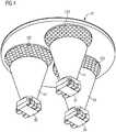
- the reading light schematically illustrated in the figures according to the preferred embodiment of the inventionhas a cylindrical housing 1 with a side wall 10, which forms the shell of a circular cylinder, and a bottom 11 and a cover plate 12.
- a mounting plate 2 with three light-emitting diodes 31, 32, 33 mounted thereonis arranged in the interior 14 of the housing 1.
- the components (not shown) of an operating circuit for the three light-emitting diodes 31, 32, 33are mounted on the mounting plate 2.
- the mounting plate 2is fixed to the bottom 11 of the housing 1, for example by means of screws or adhesive. Alternatively, the mounting plate 2 but also be fixed to the side wall 10.
- the viewing angle(viewing angle, measured with reference to the surface normal of the upper side of the light-emitting diode) at which 50% of the maximum luminous flux of the light-emitting diode is present is 120 degrees.
- formulated on the mantle of a cone whose tip is on the top of the light emitting diode 31, 32 or 33 and whose opening angle is 120 degreesare still 50% of the maximum luminous flux of the LED, wherein the maximum luminous flux in the cone axis is measured. This means that the light emitting diodes 31, 32, 33 generate a relatively wide light cone during their operation.
- the Lichteinkoppel structure 411, 421, 431each at a small distance from the top 310th , 320 or 330 of the respective light-emitting diode 31, 32 or 33 is arranged.
- the distance between the upper side 310, 320, 330 of the light-emitting diodes 31, 32, 33 and the light coupling surface 411, 421, 431 of the conical light guides 41, 42, 43is as small as possible, and preferably not greater than 0.3 mm, to light losses when crossing into the light guides 41, 42, 43 to minimize.
- the three conical light guides 41, 42, 43each consist of polycarbonate (PC).
- the conical light guides 41, 42, 43are each frustoconical. Their light coupling surface 411, 421, 431 each has a diameter of 1.3 mm.
- the three conical light guides 41, 42, 43also each have a light output surface 412, 422, 432, the light incident surface 411, 421, 431 of the respective light guide 41, 42, 43 opposite.
- the light outcoupling surfaces 412, 422, 432are convexly curved and have a radius of curvature of 5.88 mm each.
- the maximum diameter of the conical or frustoconical light guides 41, 42, 43 in the region of the light outcoupling surfaces 412, 422, 432is 7 mm.
- each conical light guide 41, 42, 43 from the light incoupling surface 411, 421, 431 to the light outcoupling surface 412, 422, 432is 8.2 mm in each case.
- the light emitted by the light-emitting diodes 31, 32, 33enters the respective light guide 41, 42 or 43 via its light input surface 411, 421 and 4431, respectively, and leaves the light guides 41, 42 and 43 via their light output surface 412, 422 and 43, respectively.
- the lens 12 of the housing 1is a light-scattering disc which is arranged at a distance of approximately 0.4 mm from the light-outcoupling surfaces 412, 422, 432 of the conical light guides 41, 42, 43.
- Each light output surface 412, 422, 432 of the conical Optical fiber 41, 42, 43is associated with a light-scattering portion 121, 122, 123 in the lens 12.
- Each light-scattering section 121, 122, 123is assigned to one of the light-outcoupling surfaces 412, 422, 432 of the conical light guides 41, 42, 43. Therefore, each light-scattering portion 121, 122, 123 covers an area of the lens 12 which is larger than the respective light-out surface 412, 422, and 432 of the conical light guides 41, 42, 43, respectively.
- the light-diffusing portions 121, 122, 123 cover the cover plate 12each have a circular disc with a diameter of 8 mm.
- the lens 12is made of polymethyl methacrylate (PMMA) and has a thickness of 0.8 mm and a diameter of 20 mm.
- PMMApolymethyl methacrylate
- the aforementioned plastic material of the lensis also known under the name Plexiglas or acrylic glass.
- the light-diffusing portions 121, 122, 123 of the lens 12each consist of a plurality of spherical cap-like microlenses 1210, 1220, 1230, which are arranged in a hexagonal or honeycomb structure in the light-scattering portions 121, 122, 123 and each have a radius of curvature of 0.5 mm and a height of 0.3 mm above the outside of the light-scattering portions 121, 122, 123 surface of the lens 12 have.
- the distance between the centers of two adjacent microlenses or hexagons in each light-scattering section 121, 122, 123 of the lens 12is 0.7 mm.
- the light-diffusing sections 121, 122, 123 with the microlenses 1210, 1220, 1230are disposed on both sides of the lens 12.
- the surface region of the cover lens 12 lying outside the light-scattering sections 121, 122, 123is designed to be transparent, for example. Alternatively, he can also be opaque.
- the hexagonal structures of the different light-scattering sections 121, 122 and 123 belonging to microlenses 1210, 1220 and 1230are arranged rotated by an angle of 20 degrees to each other. This situation is schematic in the FIGS. 5 and 6 for the light-scattering sections 121 and 122.
- the hexagonal structure of the microlenses 1230 of the third light-diffusing portion 123are also rotated by an angle of 20 degrees with respect to the hexagonal structure of the microlenses 1210 of the first light-diffusing portion 121. Accordingly, the hexagonal structures of the second 122 and third light scattering portion are arranged rotated by an angle of 40 degrees to each other. Due to the symmetry of the hexagonal structure, however, it is not possible to differentiate between a twist of 20 degrees and a twist of 40 degrees. Like out FIG. 5 or 6 As can be seen immediately, any rotation of the hexagonal structure about an axis of rotation passing through the center of a hexagon translates the hexagonal structure into itself by an angle of 60 degrees. Therefore, the hexagonal structures of the three are provided with microlenses 1210, 1200, 1230 Sections 121, 122, 123 of the light-diffusing lens 12 each arranged rotated by an angle of 20 degrees from each other.
- white lightcan also be generated.
- the light emitted by the light sources of a light-emitting diode arraycan be coupled into a single conical light guide.
Landscapes
- Engineering & Computer Science (AREA)
- General Engineering & Computer Science (AREA)
- Mechanical Engineering (AREA)
- Non-Portable Lighting Devices Or Systems Thereof (AREA)
- Arrangements Of Lighting Devices For Vehicle Interiors, Mounting And Supporting Thereof, Circuits Therefore (AREA)
Description
Translated fromGermanDie Erfindung betrifft eine Leseleuchte für den Innenraum von Kraftfahrzeugen. Derartige Leseleuchten sind üblicherweise in dem Dachhimmel des Kraftfahrzeugs integriert und erzeugen nach dem Einschalten einen eng begrenzten Lichtkegel auf der Fahrer- oder Beifahrerseite des Kraftfahrzeugs um beispielsweise nach Eintritt der Dämmerung das lesen einer Landkarte oder dergleichen im Kraftfahrzeug zu ermöglichen. Als Lichtquelle wird in derartigen Leseleuchten üblicherweise eine Glühlampe verwendet, die zusammen mit einem Reflektor einen eng begrenzten Lichtkegel generiert. Glühlampen haben allerdings den Nachteil einer vergleichsweise geringen Lebensdauer.The invention relates to a reading light for the interior of motor vehicles. Such reading lights are usually integrated in the headliner of the motor vehicle and generate after switching a narrow beam on the driver or passenger side of the motor vehicle to allow, for example after dawn reading a map or the like in the vehicle. The light source used in such reading lights is usually an incandescent lamp which, together with a reflector, generates a narrow beam of light. However, incandescent lamps have the disadvantage of a comparatively short life.
Eine gattungsgemäße Leseleuchte für den Innenraum von Kraftfahrzeugen wird im
Es ist Aufgabe der Erfindung, eine Leseleuchte für den Innenraum von Kraftfahrzeugen mit einer Lichtquelle mit längerer Lebensdauer bereitzustellen.It is an object of the invention to provide a reading light for the interior of motor vehicles with a light source with longer life.
Diese Aufgabe wird durch eine Leseleuchte mit den Merkmalen aus dem Anspruch 1 gelöst. Besonders vorteilhafte Ausführungen der Erfindung sind in den abhängigen Ansprüchen beschrieben.This object is achieved by a reading light with the features of
Die erfindungsgemäße Leseleuchte für den Innenraum von Kraftfahrzeugen besitzt mehrere Leuchtdioden, die auf einer Montageplatte angeordnet sind, und mehrere konische Lichtleiter, wobei jeder konische Lichtleiter eine, mindestens einer Leuchtdiode zugewandte Lichteinkoppelfläche und eine Lichtauskoppelfläche aufweist, sowie eine Licht streuende Scheibe, welche die Lichtauskoppelflächen der konischen Lichtleiter abdeckt und die den Lichtauskoppelflächen der konischen Lichtleiter zugeordnete, mit Mikrolinsen versehene Abschnitte besitzt.The reading lamp according to the invention for the interior of motor vehicles has a plurality of light-emitting diodes, which are arranged on a mounting plate, and a plurality of conical optical fibers, each conical optical fiber, at least one light-emitting diode facing Lichteinkoppelfläche and a Lichtauskoppelfläche, and a light-scattering disc, which the Lichtauskoppelflächen the conical light guide covers and the light outcoupling surfaces the conical light guide has associated, provided with microlens sections.
Durch die Verwendung von Leuchtdioden anstelle einer Glühlampe weist die Lichtquelle der erfindungsgemäßen Leseleuchte eine längere Lebensdauer als die Lichtquelle herkömmlicher Leseleuchten auf. Da bei der erfindungsgemäßen Leseleuchte mehrere Leuchtdioden als Lichtquelle kombiniert werden und diese Leuchtdioden zusammen mit konischen Lichtleitern verwendet werden, welche die Divergenz des von den Leuchtdioden emittierten Lichts reduzieren, und weiterhin eine Licht streuende Scheibe vorgesehen ist, wird mit der erfindungsgemäßen Leseleuchte hinsichtlich Lichtbündelung, Beleuchtungsstärke und Lichthomogenität ein vergleichbar gutes Resultat wie mit einer herkömmlichen Leseleuchte erreicht. Die Licht streuende Scheibe der erfindungsgemäßen Leseleuchte besitzt mit Mikrolinsen versehene Abschnitte, die der Lichtauskoppelfläche jeweils eines konischen Lichtleiters zugeordnet sind. Die mit Mikrolinsen versehenen Abschnitte bewirken eine Streuung des aus den Lichtauskoppelflächen der konischen Lichtleiter austretenden Lichts und ermöglichen dadurch eine Mischung und Homogenisierung des von den Leuchtdioden emittierten Lichts.By using light-emitting diodes instead of an incandescent lamp, the light source of the reading lamp according to the invention has a longer life than the light source of conventional reading lights. Since in the reading light according to the invention a plurality of LEDs are combined as a light source and these LEDs are used together with conical optical fibers, which reduce the divergence of the light emitted by the LEDs, and further provided a light-scattering disc is provided with the reading light according to the invention in terms of light bundling, illuminance and light homogeneity achieves a comparably good result as with a conventional reading light. The light-scattering disk of the reading lamp according to the invention has sections provided with microlenses which are assigned to the light output surface of a respective conical light guide. The micro-lensed portions cause scattering of the light emerging from the light outcoupling surfaces of the conical light guides and thereby allow mixing and homogenization of the light emitted by the light-emitting diodes.
Um im Fernfeld vor der erfindungsgemäßen Leseleuchte ein gutes Ergebnis bei der Mischung und Homogenisierung des von allen Leuchtdioden emittierten Lichts zu erzielen, sind die Mikrolinsen der einzelnen Licht streuenden, mit Mikrolinsen versehenen Abschnitte der Licht streuenden Scheibe jeweils in einer hexagonalen Struktur angeordnet, wobei die hexagonalen Strukturen der verschiedenen, mit Mikrolinsen versehenen Abschnitte gegeneinander verdreht angeordnet sind.In order to achieve a good result in the far field in front of the reading light according to the invention in the mixing and homogenization of the light emitted by all light-emitting diodes, the micro-lenses of the individual light-scattering, microlensed portions of the light-scattering disk are each arranged in a hexagonal structure, wherein the hexagonal structures the various micro-lensed portions are arranged rotated against each other.
Die Kombination von mehreren Leuchtdioden mit den vorgenannten konischen Lichtleitern und der Licht streuende Scheibe erlaubt es, Leuchtdioden aus unterschiedlichen Fertigungschargen mit entsprechend unterschiedlichen Lichtemissionseigenschaften in der erfindungsgemäßen Leseleuchte als Lichtquelle zu verwenden, weil das von diesen Leuchtdioden emittierte Licht mittels der konischen Lichtleiter und der Licht streuende Scheibe im Fernfeld gemischt und homogenisiert wird, so dass weißes Licht der gewünschten Farbtemperatur bzw. der gewünschten Farbkoordinaten gemäß dem CIE-Normfarbsystem von 1931 erzeugt wird. Für diesen Zweck ist die Verwendung von mindestens drei Leuchtdioden in der erfindungsgemäßen Leseleuchte vorteilhaft, die jeweils weißes Licht erzeugen. Beispielsweise kann dieselbe Farbtemperatur bzw. können dieselben Farbkoordinaten für das weiße Licht der Leseleuchte durch unterschiedliche Kombinationen von jeweils drei Leuchtdioden erreicht werden. So kann zum Beispiel eine Leuchtdiode, die weißes Licht mit stark gelblicher Tönung emittiert, mit zwei Leuchtdioden kombiniert werden, die weißes Licht mit bläulicher Tönung emittieren, oder es können zwei Leuchtdioden, die weißes Licht mit schwach gelblicher Tönung emittieren, mit einer Leuchtdiode kombiniert werden, die weißes Licht mit schwach bläulicher Tönung emittiert, um eine vorbestimmte gewünschte Farbtemperatur für das Licht der Leseleuchte zu erhalten. Vorzugsweise enthält die erfindungsgemäße Leseleuchte daher mehrere Leuchtdioden, die jeweils weißes Licht mit unterschiedlicher Farbtemperatur bzw. unterschiedlichen Farbkoordinaten erzeugen. Die Licht streuende Scheibe mischt und homogenisiert das von den unterschiedlichen Leuchtdioden emittierte Licht, so dass im Fernfeld der Leseleuchte weißes Licht der gewünschten Farbtemperatur bzw. mit den gewünschten Farbkoordinaten vorliegt.The combination of a plurality of light emitting diodes with the aforementioned conical optical fibers and the light scattering disc allows light emitting diodes from different production batches with correspondingly different light emission properties in the reading light according to the invention to be used as a light source, because the light emitted by these light emitting diodes by means of the conical light guide and the light Disc is mixed and homogenized in the far field, so that white light of the desired color temperature or the desired color coordinates according to the CIE standard color system of 1931 is generated. For this purpose, the use of at least three light-emitting diodes in the reading light according to the invention is advantageous, which each generate white light. For example, the same color temperature or the same color coordinates for the white light of the reading light can be achieved by different combinations of three light-emitting diodes. For example, a light-emitting diode that emits white light with a strong yellowish tint may be combined with two light-emitting diodes that emit white light with bluish tint, or two light-emitting diodes that emit white light with a faint tinge may be combined with a light-emitting diode which emits white light with a faint bluish tint to obtain a predetermined desired color temperature for the light of the reading light. The reading lamp according to the invention therefore preferably contains a plurality of light-emitting diodes, each of which has white light with a different color temperature or different colors Create color coordinates. The light-diffusing slice mixes and homogenizes the light emitted by the different light-emitting diodes so that in the far field of the reading light there is white light of the desired color temperature or with the desired color coordinates.
Vorteilhafterweise sind die konischen Lichtleiter kegelstumpfartig ausgebildet, um eine Lichteinkoppelfläche und eine Lichtauskoppelfläche mit größeren Abmessungen als die Lichteinkoppelfläche zu ermöglichen. Die Lichtauskoppelflächen der konischen bzw. kegelstumpfartigen Lichtleiter sind vorzugsweise konvex gewölbt, um die Reflexion des aus den Lichtleitern austretenden Lichts an der Lichtauskoppelfläche zu minimieren.Advantageously, the conical optical fibers are frusto-conical in order to allow a light input surface and a light output surface with larger dimensions than the light input surface. The light outcoupling surfaces of the conical or truncated cone-like light guides are preferably curved convexly in order to minimize the reflection of the light emerging from the light guides at the light outcoupling surface.
Die erfindungsgemäße Leseleuchte weist vorzugsweise ein Gehäuse auf, in dessen Innenraum die Leuchtdioden und die konischen Lichtleiter angeordnet sind, um die vorgenannten Komponenten vor Beschädigung zu schützen und um die Leseleuchte als vorgefertigtes Modul in dem Kraftfahrzeug montieren zu können. Die Licht streuende Scheibe der erfindungsgemäßen Leseleuchte ist in vorteilhafter Weise als Abschlussscheibe ausgebildet, die eine Wand des Gehäuses bildet, durch die das von den Leuchtdioden generierte Licht austritt.The reading lamp according to the invention preferably has a housing, in the interior of which the light-emitting diodes and the conical light guides are arranged to protect the aforementioned components from damage and to mount the reading light as a prefabricated module in the motor vehicle can. The light-scattering disc of the reading lamp according to the invention is advantageously designed as a cover plate, which forms a wall of the housing, through which the light generated by the light emitting diodes exits.
Vorzugsweise ist für jede Leuchtdiode jeweils ein konischer Lichtleiter vorgesehen, um einen möglichst gut gebündelten Lichtkegel mit möglichst homogener Mischung des von den Leuchtdioden emittierten Lichts im Fernfeld der Leseleuchte zu erhalten.Preferably, a conical light guide is provided in each case for each light-emitting diode, in order to obtain a light cone bundled as well as possible with as homogeneous a mixture of the light emitted by the light-emitting diodes in the far field of the reading light.
Es zeigen:
Figur 1- Eine Seitenansicht einer Leseleuchte gemäß dem bevorzugten Ausführungsbeispiel der Erfindung in teilweise geschnittener Darstellung
Figur 2- Eine Draufsicht auf die Abschlussscheibe der in
Figur 1 - Figur 3
- Eine isometrische Darstellung der Oberseite der in
Figur 1 - Figur 4
- Eine isometrische Darstellung der Unterseite der in
Figur 1 - Figur 5
- Die hexagonale Struktur der Mikrolinsen des ersten Licht streuenden Abschnitts der Licht streuenden Abschlussscheibe der in
Figur 1 - Figur 6
- Die hexagonale Struktur der Mikrolinsen des zweiten Licht streuenden Abschnitts der Licht streuenden Abschlussscheibe der in
Figur 1
- FIG. 1
- A side view of a reading light according to the preferred embodiment of the invention in a partially sectioned view
- FIG. 2
- A top view of the lens of the in
FIG. 1 pictured reading light - FIG. 3
- An isometric illustration of the top of the in
FIG. 1 Pictured reading light without housing - FIG. 4
- An isometric illustration of the underside of the in
FIG. 1 Pictured reading light without housing - FIG. 5
- The hexagonal structure of the microlenses of the first light-scattering section of the light-diffusing lens of the
FIG. 1 pictured reading light - FIG. 6
- The hexagonal structure of the microlenses of the second light-scattering section of the light-scattering lens of in
FIG. 1 pictured reading light
Nachstehend wird die Erfindung anhand eines bevorzugten Ausführungsbeispiels näher erläutert.The invention will be explained in more detail below with reference to a preferred embodiment.
Die in den Figuren schematisch dargestellte Leseleuchte gemäß dem bevorzugten Ausführungsbeispiel der Erfindung besitzt ein zylindrisches Gehäuse 1 mit einer Seitenwand 10, die den Mantel eines Kreiszylinders formt, und einem Boden 11 sowie einer Abschlussscheibe 12. In dem Innenraum 14 des Gehäuses 1 ist eine Montageplatte 2 mit drei darauf montierten Leuchtdioden 31, 32, 33 angeordnet. Zusätzlich sind auf der Montageplatte 2 auch die Komponenten (nicht abgebildet) einer Betriebsschaltung für die drei Leuchtdioden 31, 32, 33 montiert. Die Montageplatte 2 ist am Boden 11 des Gehäuses 1 beispielsweise mittels Schrauben oder Klebstoff fixiert. Alternativ kann die Montageplatte 2 aber auch an der Seitenwand 10 fixiert sein.The reading light schematically illustrated in the figures according to the preferred embodiment of the invention has a
Die drei Leuchtdioden 31, 32, 33 sind auf der Montageplatte 2 derart angeordnet, dass sie die Eckpunkte eines Dreiecks bilden. Bei den Leuchtdioden 31, 32,33 handelt es sich um Leuchtdioden der Firma OSRAM, die unter dem Namen Power Topled LW E6SG verkauft werden. Diese Leuchtdioden 31, 32, 33 erzeugen während ihres Betriebs jeweils weißes Licht mit einem Lichtstrom von ca. 5 Im. Die Leuchtdioden 31, 32, 33 stammen aus unterschiedlichen Fertigungschargen und sind hinsichtlich der Farbkoordinaten des von ihnen erzeugten weißen Lichts derart ausgewählt und kombiniert, dass das von der Leseleuchte emittierte Licht weißes Licht mit den Farbkoordinaten x=0,314 und y=0,286 ist. Die Leuchtdioden 31, 32, 33 basieren auf der so genannten GaN-Technologie und besitzen einen maximalen optischen Wirkungsgrad von 50 lm/W bei einem Strom von 20 mA. Die Leuchtdioden 31, 32, 33 besitzen ein Silikonharz-Package, aber keine optische Linse. Die Lichtabgabe der Leuchtdioden 31, 32, 33 erfolgt über ihre von der Montageplatte 2 abgewandte Oberfläche, die hier nachstehend auch als Oberseite 310, 320 bzw. 330 der jeweiligen Leuchtdiode 31, 32 bzw. 33 bezeichnet wird. Jede der Leuchtdioden ist daher näherungsweise ein so genannter Lambert-Strahler. Der Viewing angle (Betrachtungswinkel, gemessen bzgl. der Flächennormalen der Oberseite der Leuchtdiode), bei dem noch 50% des maximalen Lichtstroms der Leuchtdiode vorliegen, beträgt 120 Grad. Oder mit anderen Worten formuliert, auf dem Mantel eines Kegels, dessen Spitze auf der Oberseite der Leuchtdiode 31, 32 oder 33 steht und dessen Öffnungswinkel 120 Grad beträgt, liegen noch 50% des maximalen Lichtstroms der Leuchtdiode vor, wobei der maximale Lichtstrom in der Kegelachse gemessen wird. Das bedeutet, dass die Leuchtdioden 31, 32, 33 während ihres Betriebs einen relativ breit gefächerten Lichtkegel erzeugen. Um diesen breit gefächerten Lichtkegel zu bündeln und die Divergenz des von den Leuchtdioden 31, 32, 33 erzeugten Lichts zu reduzieren, sind drei konische Lichtleiter 41, 42, 43 vorgesehen, deren Lichteinkoppelfläche 411, 421, 431 jeweils im geringen Abstand von der Oberseite 310, 320 oder 330 der jeweiligen Leuchtdiode 31, 32 oder 33 angeordnet ist. Der Abstand zwischen der Oberseite 310, 320, 330 der Leuchtdioden 31, 32, 33 und der Lichteinkoppelfläche 411, 421, 431 der konischen Lichtleiter 41, 42, 43 ist so klein wie möglich und vorzugsweise nicht größer als 0,3 mm, um Lichtverluste beim Übertritt in die Lichtleiter 41, 42, 43 zu minimieren.The three light-emitting
Die drei konischen Lichtleiter 41, 42, 43 bestehen jeweils aus Polykarbonat (PC). Die konischen Lichtleiter 41, 42, 43 sind jeweils kegelstumpfartig ausgebildet. Ihre Lichteinkoppelfläche 411, 421, 431 besitzt jeweils einen Durchmesser von 1,3 mm. Die drei konischen Lichtleiter 41, 42, 43 besitzen außerdem jeweils eine Lichtauskoppelfläche 412, 422, 432, die der Lichteinkoppelfläche 411, 421, 431 des jeweiligen Lichtleiters 41, 42, 43 gegenüberliegt. Die Lichtauskoppelflächen 412, 422, 432 sind konvex gewölbt und besitzen einen Krümmungsradius von jeweils 5,88 mm. Der maximale Durchmesser der konischen bzw. kegelstumpfartigen Lichtleiter 41, 42, 43 im Bereich der Lichtauskoppelflächen 412, 422, 432 beträgt 7 mm. Die Höhe jedes konischen Lichtleiters 41, 42, 43 von der Lichteinkoppelfläche 411, 421, 431 bis zur Lichtauskoppelfläche 412, 422, 432 beträgt jeweils 8,2 mm. Das von den Leuchtdioden 31, 32, 33 emittierte Licht tritt in den jeweiligen Lichtleiter 41, 42 bzw. 43 über seine Lichteinkoppelfläche 411, 421 bzw. 4431 ein und verlässt die Lichtleiter 41 ,42 bzw. 43 über deren Lichtauskoppelfläche 412, 422 bzw. 432.The three conical light guides 41, 42, 43 each consist of polycarbonate (PC). The conical light guides 41, 42, 43 are each frustoconical. Their
Bei der Abschlussscheibe 12 des Gehäuses 1 handelt es sich um eine Licht streuende Scheibe, die in einem Abstand von ungefähr 0,4 mm zu den Lichtauskoppelflächen 412, 422, 432 der konischen Lichtleiter 41, 42, 43 angeordnet ist. Die Abschlussscheibe 12 verschließt die dem Boden gegenüberliegende Stirnseite des zylindrischen Gehäuses 1 und ihre drei Licht streuenden Abschnitte 121, 122, 123 homogenisieren und mischen das Licht, das aus den Lichtauskoppelflächen 412, 422, 432 der drei konischen Lichtleiter 41, 42, 43 austritt, so dass im Fernfeld der Leseleuchte, das heißt ein paar Dezimeter entfernt von der Abschlussscheibe 12 und von der Leseleuchte, während des Betriebs homogenes weißes Licht mit den vorgenannten Farbkoordinaten X=0,314 und y=0,286 verfügbar ist. Jeder Lichtauskoppelfläche 412, 422, 432 der konischen Lichtleiter 41, 42, 43 ist ein Licht streuender Abschnitt 121, 122, 123 in der Abschlussscheibe 12 zugeordnet. Jeder Licht streuende Abschnitt 121, 122, 123 ist einer der Lichtauskoppelflächen 412, 422, 432 der konischen Lichtleiter 41, 42, 43 zugeordnet. Daher bedeckt jeder Licht streuende Abschnitt 121, 122, 123 einen Flächenbereich der Abschlussscheibe 12, der größer ist als die jeweilige Lichtauskoppelfläche 412, 422 bzw. 432 der konischen Lichtleiter 41, 42, 43. Vorzugsweise bedecken die Licht streuende Abschnitte 121, 122, 123 der Abschlussscheibe 12 jeweils eine Kreisscheibe mit einem Durchmesser von 8 mm. In der Darstellung gemäß den
Die hexagonalen Strukturen der zu unterschiedlichen Licht streuenden Abschnitten 121, 122 bzw. 123 gehörenden Mikrolinsen 1210, 1220 bzw. 1230 sind um einen Winkel von 20 Grad gegeneinander verdreht angeordnet. Dieser Sachverhalt ist schematisch in den
Die hemisphärischen Mikrolinsen 1210 des ersten Licht streuenden Abschnitts 121 sind in einer hexagonalen Struktur angeordnet, deren Ausrichtung im Raum, beispielsweise bezüglich eines Durchmessers der Abschlussscheibe 12, schematisch durch die drei Geraden g1, g2 und g3 definiert ist (
Am Rand der Abschlussscheibe 12 ist eine Aussparung 120 angeordnet, die einen passgerechten, an der Seitenwand 10 des Gehäuses 1 angeformten Steg aufnimmt.At the edge of the
Die Erfindung beschränkt sich nicht auf das oben näher erläuterte Ausführungsbeispiel. Insbesondere bezeichnet der Begriff Leuchtdiode nicht nur den oben zitierten speziellen Typ von Leuchtdioden, sondern steht beispielsweise auch für einen Leuchtdiodenchip oder für ein Leuchtdioden-Array. Außerdem kann auch das Licht von mehreren Leuchtdioden in die Lichteinkoppelfläche eines konischen Lichtleiters eingekoppelt werden. Beispielsweise kann das Licht von einer Leuchtdiodeneinheit, bestehend aus mindestens drei Halbleiterlichtquellen, die rotes, grünes und blaues Licht emittieren, oder bestehend aus mindestens zwei Halbleiterlichtquellen, die mintgrünes und rotes bzw. orangefarbenes Licht emittieren, in die Lichtleitereinkoppelfläche eines einzigen konischen Lichtleiters eingekoppelt werden. Mittels der vorgenannten Kombinationen von mindestens drei Halbleiterlichtquellen, die rotes, grünes und blaues Licht emittieren, oder der Kombination von mindestens zwei Halbleiterlichtquellen, die mintgrünes und rotes bzw. orangefarbenes Licht emittieren, kann ebenfalls weißes Licht erzeugt werden. Weiterhin kann beispielsweise insbesondere im Fall von Leuchtdioden-Arrays das von den Lichtquellen eines Leuchtdioden-Arrays emittierte Licht in einen einzigen konischen Lichtleiter eingekoppelt werden.The invention is not limited to the embodiment explained in more detail above. In particular, the term light-emitting diode not only designates the special type of light-emitting diodes cited above, but also stands, for example, for a light-emitting diode chip or for a light-emitting diode array. In addition, the light of several LEDs can be coupled into the light input surface of a conical optical fiber. For example, that can Light from a light emitting diode unit, consisting of at least three semiconductor light sources emitting red, green and blue light, or consisting of at least two semiconductor light sources emitting mint green and red or orange light are coupled into the optical fiber coupling surface of a single conical optical fiber. By means of the aforementioned combinations of at least three semiconductor light sources which emit red, green and blue light, or the combination of at least two semiconductor light sources which emit mint green and red or orange light, white light can also be generated. Furthermore, for example, in particular in the case of light-emitting diode arrays, the light emitted by the light sources of a light-emitting diode array can be coupled into a single conical light guide.
Claims (8)
- Reading luminaire for the interior of motor vehicles, comprising- a plurality of light-emitting diodes (31, 32, 33) arranged on a mounting plate (2), and comprising- a plurality of conical optical waveguides (41, 42, 43), wherein each conical optical waveguide (41, 42, 43) has a light coupling-in surface (411, 421, 431) facing at least one light-emitting diode (31, 32, 33), and a light coupling-out surface (412, 422, 432), and comprising- a light-scattering sheet (12) covering the light coupling-out surfaces (412, 422, 432) of the conical optical waveguides (41, 42, 43), wherein the light-scattering sheet (12) has sections (121, 122, 123) provided with microlenses, said sections being assigned to the light coupling-out surfaces (412, 422, 432) of the conical optical waveguides (41, 42, 43),characterized in that the sections (121, 122, 123) of the light-scattering sheet (12) provided with microlenses each occupy an area greater than or equal to that of the respective light coupling-out surface (412, 422, 432) of the corresponding conical optical waveguide (41, 42, 43), wherein the microlenses (1210, 1220, 1230) of each section (121, 122, 123) provided with microlenses are arranged in each case in a hexagonal structure, and wherein the hexagonal structures of the sections (121, 122, 123) provided with microlenses are arranged in a manner rotated relative to one another.
- Reading luminaire according to Claim 1, wherein the conical optical waveguides (41, 42, 43) are embodied in a truncated-cone-like fashion.
- Reading luminaire according to Claim 1 or 2, wherein the light coupling-out surfaces (412, 422, 432) of the conical optical waveguides (41, 42, 43) are in each case larger than their light coupling-in surfaces (411, 421, 321) and the light coupling-out surfaces (412, 422, 432) are convexly curved.
- Reading luminaire according to any of Claims 1 to 3, wherein the light-emitting diodes (31, 32, 33) are embodied as light-emitting diodes which emit white light.
- Reading luminaire according to Claim 4, wherein the light-emitting diode (31, 32, 33) in each case generate white light having different colour coordinates during their operation.
- Reading luminaire according to any of Claims 1 to 5, wherein the reading luminaire has a housing (1), in the interior (14) of which the light-emitting diodes (31, 32, 33) and the conical optical waveguides (41, 42, 43) are arranged.
- Reading luminaire according to Claim 6, wherein the light-scattering sheet (12) is embodied as a closure sheet forming a wall of the housing (1).
- Reading luminaire according to any of Claims 1 to 7, wherein a respective conical optical waveguide (41, 42, 43) is provided for each of the light-emitting diodes (31, 32, 33).
Applications Claiming Priority (2)
| Application Number | Priority Date | Filing Date | Title |
|---|---|---|---|
| DE102010039859ADE102010039859A1 (en) | 2010-08-27 | 2010-08-27 | Reading light for motor vehicles |
| PCT/EP2011/063608WO2012025363A1 (en) | 2010-08-27 | 2011-08-08 | Reading light for motor vehicles |
Publications (2)
| Publication Number | Publication Date |
|---|---|
| EP2534003A1 EP2534003A1 (en) | 2012-12-19 |
| EP2534003B1true EP2534003B1 (en) | 2017-07-26 |
Family
ID=44582947
Family Applications (1)
| Application Number | Title | Priority Date | Filing Date |
|---|---|---|---|
| EP11745951.1AActiveEP2534003B1 (en) | 2010-08-27 | 2011-08-08 | Reading light for motor vehicles |
Country Status (3)
| Country | Link |
|---|---|
| EP (1) | EP2534003B1 (en) |
| DE (1) | DE102010039859A1 (en) |
| WO (1) | WO2012025363A1 (en) |
Families Citing this family (8)
| Publication number | Priority date | Publication date | Assignee | Title |
|---|---|---|---|---|
| DE102012200416B4 (en) | 2012-01-12 | 2018-03-01 | Osram Opto Semiconductors Gmbh | OPTOELECTRONIC MODULE AND METHOD FOR PRODUCING AN OPTOELECTRONIC MODULE |
| DE102015115341A1 (en)* | 2015-09-11 | 2017-03-16 | Hella Kgaa Hueck & Co. | Lighting device for the interior of a vehicle |
| FR3041075B1 (en)* | 2015-09-15 | 2020-07-17 | Valeo Vision | LIGHT DEVICE, ESPECIALLY FOR A MOTOR VEHICLE |
| DE102015115579A1 (en)* | 2015-09-16 | 2017-03-16 | Hella Kgaa Hueck & Co. | Lighting device for the interior of a vehicle |
| FR3048068B1 (en)* | 2016-02-24 | 2022-08-05 | Valeo Vision | LIGHTING SYSTEM FOR MOTOR VEHICLE CABIN |
| DE102016009660B4 (en)* | 2016-08-09 | 2021-09-09 | Daimler Ag | Illuminated trim |
| DE102017215892A1 (en)* | 2017-09-08 | 2019-03-14 | Volkswagen Aktiengesellschaft | Lighting device for a vehicle |
| DE102018125438A1 (en) | 2018-10-15 | 2020-04-16 | HELLA GmbH & Co. KGaA | Lighting device for vehicles |
Family Cites Families (12)
| Publication number | Priority date | Publication date | Assignee | Title |
|---|---|---|---|---|
| US6424786B1 (en)* | 1996-12-02 | 2002-07-23 | Honeywell International Inc. | Illumination assembly |
| DE19908040A1 (en)* | 1999-02-24 | 2000-08-31 | Diehl Stiftung & Co | Device for illuminating rooms, bodies or surfaces |
| DE29919032U1 (en)* | 1999-10-29 | 1999-12-30 | Hella KG Hueck & Co., 59557 Lippstadt | Interior lights for motor vehicles |
| US6527411B1 (en)* | 2000-08-01 | 2003-03-04 | Visteon Corporation | Collimating lamp |
| DE10231325A1 (en)* | 2002-07-11 | 2004-02-12 | Hella Kg Hueck & Co. | Lighting device for vehicles |
| DE10231324A1 (en)* | 2002-07-11 | 2004-01-22 | Hella Kg Hueck & Co. | Interior light for vehicles, has film-like flat radiator light source, and optical element arranged opposite each light layer region for focusing light from relevant light layer region |
| DE10234110B4 (en)* | 2002-07-26 | 2010-04-08 | Automotive Lighting Reutlingen Gmbh | Luminaire for vehicles, in particular motor vehicles |
| US7483220B2 (en)* | 2003-12-22 | 2009-01-27 | Auer Lighting Gmbh | Optical arrangement with stepped lens |
| DE102004042125B4 (en)* | 2004-08-30 | 2008-05-08 | Schefenacker Vision Systems Germany Gmbh & Co. Kg | Lighting unit with a large number of curved surface elements |
| US7888875B2 (en)* | 2006-11-21 | 2011-02-15 | Ceit Entreprises | Lighting device such as a LED reading light |
| DE102007056402A1 (en) | 2007-11-23 | 2009-05-28 | Osram Gesellschaft mit beschränkter Haftung | Optical component and lighting device |
| DE102008029511A1 (en)* | 2008-06-21 | 2010-02-11 | Airbus Deutschland Gmbh | Reading or spot light |
- 2010
- 2010-08-27DEDE102010039859Apatent/DE102010039859A1/ennot_activeWithdrawn
- 2011
- 2011-08-08WOPCT/EP2011/063608patent/WO2012025363A1/enactiveApplication Filing
- 2011-08-08EPEP11745951.1Apatent/EP2534003B1/enactiveActive
Non-Patent Citations (1)
| Title |
|---|
| None* |
Also Published As
| Publication number | Publication date |
|---|---|
| WO2012025363A1 (en) | 2012-03-01 |
| EP2534003A1 (en) | 2012-12-19 |
| DE102010039859A1 (en) | 2012-03-01 |
Similar Documents
| Publication | Publication Date | Title |
|---|---|---|
| EP2534003B1 (en) | Reading light for motor vehicles | |
| EP1231429B1 (en) | Color illumination device | |
| EP1842723B1 (en) | Headlamp and headlamp element | |
| DE102005056654B4 (en) | A light-emitting device comprising a plurality of overlapping panels forming recesses from which light is emitted | |
| EP1618430B1 (en) | Light source | |
| DE102010056313C5 (en) | Lighting device of a motor vehicle | |
| DE102007002403B4 (en) | Lighting arrangement, multiple light module, luminaire and their use | |
| EP1378771A1 (en) | Interior lighting | |
| DE102009017495A1 (en) | lighting device | |
| DE112011105462B4 (en) | LED module for double-sided lighting and double-sided LED lighting device with the same | |
| DE102012209131A1 (en) | LIGHTING DEVICE WITH SEMICONDUCTOR LIGHT SOURCES AND COMMON DIFFUSER | |
| DE102012210743A1 (en) | Lighting device e.g. LED-lighting module, has light sensor arranged at distance opposite to semiconductor light sources that are designed with different colors, and photoconductive optic arranged upstream of light sensor | |
| DE102011076621A1 (en) | Lighting device for a motor vehicle | |
| DE102009047487A1 (en) | light module | |
| DE102014110225A1 (en) | vehicle light | |
| DE102014200369A1 (en) | Areal illuminator with planar light guide | |
| DE102016108692A1 (en) | LED and light module | |
| DE102006004996A1 (en) | Light mixer for use in e.g. medical area, has transparent body provided with admission area with surface, through which light enters into body and emitting area with surface, through which light escapes from body and overlays optical path | |
| DE102012203941B4 (en) | LED lighting device with anti-glare effect | |
| DE102016125581A1 (en) | Lighting device and motor vehicle | |
| DE102006004581A1 (en) | Light-module for e.g. interior lighting of aeroplane, has surface mountable semiconductor components emitting radiation, and optical device e.g. diffractive unit, that focuses radiation, which is blended by optical unit of one component | |
| DE20014114U1 (en) | Illuminating or lighting device with Fresnel optics | |
| DE102012205188A1 (en) | LED lamp has perforated plate that is provided with several holes which are filled with transparent material, and light exit opening is provided at front of housing, through which primary light of main light beam of LED is made to pass | |
| EP2982903A2 (en) | Light assembly and lighting device equipped with the same | |
| DE10164033B4 (en) | Optoelectronic component with a plurality of light sources |
Legal Events
| Date | Code | Title | Description |
|---|---|---|---|
| PUAI | Public reference made under article 153(3) epc to a published international application that has entered the european phase | Free format text:ORIGINAL CODE: 0009012 | |
| 17P | Request for examination filed | Effective date:20120911 | |
| AK | Designated contracting states | Kind code of ref document:A1 Designated state(s):AL AT BE BG CH CY CZ DE DK EE ES FI FR GB GR HR HU IE IS IT LI LT LU LV MC MK MT NL NO PL PT RO RS SE SI SK SM TR | |
| RAP1 | Party data changed (applicant data changed or rights of an application transferred) | Owner name:OSRAM GMBH | |
| RAP1 | Party data changed (applicant data changed or rights of an application transferred) | Owner name:OSRAM GMBH | |
| DAX | Request for extension of the european patent (deleted) | ||
| REG | Reference to a national code | Ref country code:DE Ref legal event code:R079 Ref document number:502011012697 Country of ref document:DE Free format text:PREVIOUS MAIN CLASS: B60Q0003020000 Ipc:B60Q0003760000 | |
| GRAP | Despatch of communication of intention to grant a patent | Free format text:ORIGINAL CODE: EPIDOSNIGR1 | |
| RIC1 | Information provided on ipc code assigned before grant | Ipc:F21V 5/00 20150101ALI20170215BHEP Ipc:B60Q 3/44 20170101ALI20170215BHEP Ipc:B60Q 3/76 20170101AFI20170215BHEP | |
| INTG | Intention to grant announced | Effective date:20170323 | |
| GRAS | Grant fee paid | Free format text:ORIGINAL CODE: EPIDOSNIGR3 | |
| GRAA | (expected) grant | Free format text:ORIGINAL CODE: 0009210 | |
| AK | Designated contracting states | Kind code of ref document:B1 Designated state(s):AL AT BE BG CH CY CZ DE DK EE ES FI FR GB GR HR HU IE IS IT LI LT LU LV MC MK MT NL NO PL PT RO RS SE SI SK SM TR | |
| REG | Reference to a national code | Ref country code:GB Ref legal event code:FG4D Free format text:NOT ENGLISH | |
| REG | Reference to a national code | Ref country code:CH Ref legal event code:EP | |
| REG | Reference to a national code | Ref country code:AT Ref legal event code:REF Ref document number:912078 Country of ref document:AT Kind code of ref document:T Effective date:20170815 | |
| REG | Reference to a national code | Ref country code:FR Ref legal event code:PLFP Year of fee payment:7 | |
| REG | Reference to a national code | Ref country code:IE Ref legal event code:FG4D Free format text:LANGUAGE OF EP DOCUMENT: GERMAN | |
| REG | Reference to a national code | Ref country code:DE Ref legal event code:R096 Ref document number:502011012697 Country of ref document:DE | |
| REG | Reference to a national code | Ref country code:NL Ref legal event code:MP Effective date:20170726 | |
| REG | Reference to a national code | Ref country code:LT Ref legal event code:MG4D | |
| PG25 | Lapsed in a contracting state [announced via postgrant information from national office to epo] | Ref country code:SE Free format text:LAPSE BECAUSE OF FAILURE TO SUBMIT A TRANSLATION OF THE DESCRIPTION OR TO PAY THE FEE WITHIN THE PRESCRIBED TIME-LIMIT Effective date:20170726 Ref country code:NO Free format text:LAPSE BECAUSE OF FAILURE TO SUBMIT A TRANSLATION OF THE DESCRIPTION OR TO PAY THE FEE WITHIN THE PRESCRIBED TIME-LIMIT Effective date:20171026 Ref country code:FI Free format text:LAPSE BECAUSE OF FAILURE TO SUBMIT A TRANSLATION OF THE DESCRIPTION OR TO PAY THE FEE WITHIN THE PRESCRIBED TIME-LIMIT Effective date:20170726 Ref country code:LT Free format text:LAPSE BECAUSE OF FAILURE TO SUBMIT A TRANSLATION OF THE DESCRIPTION OR TO PAY THE FEE WITHIN THE PRESCRIBED TIME-LIMIT Effective date:20170726 Ref country code:HR Free format text:LAPSE BECAUSE OF FAILURE TO SUBMIT A TRANSLATION OF THE DESCRIPTION OR TO PAY THE FEE WITHIN THE PRESCRIBED TIME-LIMIT Effective date:20170726 Ref country code:NL Free format text:LAPSE BECAUSE OF FAILURE TO SUBMIT A TRANSLATION OF THE DESCRIPTION OR TO PAY THE FEE WITHIN THE PRESCRIBED TIME-LIMIT Effective date:20170726 | |
| PG25 | Lapsed in a contracting state [announced via postgrant information from national office to epo] | Ref country code:IS Free format text:LAPSE BECAUSE OF FAILURE TO SUBMIT A TRANSLATION OF THE DESCRIPTION OR TO PAY THE FEE WITHIN THE PRESCRIBED TIME-LIMIT Effective date:20171126 Ref country code:RS Free format text:LAPSE BECAUSE OF FAILURE TO SUBMIT A TRANSLATION OF THE DESCRIPTION OR TO PAY THE FEE WITHIN THE PRESCRIBED TIME-LIMIT Effective date:20170726 Ref country code:ES Free format text:LAPSE BECAUSE OF FAILURE TO SUBMIT A TRANSLATION OF THE DESCRIPTION OR TO PAY THE FEE WITHIN THE PRESCRIBED TIME-LIMIT Effective date:20170726 Ref country code:PL Free format text:LAPSE BECAUSE OF FAILURE TO SUBMIT A TRANSLATION OF THE DESCRIPTION OR TO PAY THE FEE WITHIN THE PRESCRIBED TIME-LIMIT Effective date:20170726 Ref country code:LV Free format text:LAPSE BECAUSE OF FAILURE TO SUBMIT A TRANSLATION OF THE DESCRIPTION OR TO PAY THE FEE WITHIN THE PRESCRIBED TIME-LIMIT Effective date:20170726 Ref country code:BG Free format text:LAPSE BECAUSE OF FAILURE TO SUBMIT A TRANSLATION OF THE DESCRIPTION OR TO PAY THE FEE WITHIN THE PRESCRIBED TIME-LIMIT Effective date:20171026 Ref country code:GR Free format text:LAPSE BECAUSE OF FAILURE TO SUBMIT A TRANSLATION OF THE DESCRIPTION OR TO PAY THE FEE WITHIN THE PRESCRIBED TIME-LIMIT Effective date:20171027 | |
| REG | Reference to a national code | Ref country code:CH Ref legal event code:PL | |
| PG25 | Lapsed in a contracting state [announced via postgrant information from national office to epo] | Ref country code:DK Free format text:LAPSE BECAUSE OF FAILURE TO SUBMIT A TRANSLATION OF THE DESCRIPTION OR TO PAY THE FEE WITHIN THE PRESCRIBED TIME-LIMIT Effective date:20170726 Ref country code:LI Free format text:LAPSE BECAUSE OF NON-PAYMENT OF DUE FEES Effective date:20170831 Ref country code:MC Free format text:LAPSE BECAUSE OF FAILURE TO SUBMIT A TRANSLATION OF THE DESCRIPTION OR TO PAY THE FEE WITHIN THE PRESCRIBED TIME-LIMIT Effective date:20170726 Ref country code:CZ Free format text:LAPSE BECAUSE OF FAILURE TO SUBMIT A TRANSLATION OF THE DESCRIPTION OR TO PAY THE FEE WITHIN THE PRESCRIBED TIME-LIMIT Effective date:20170726 Ref country code:CH Free format text:LAPSE BECAUSE OF NON-PAYMENT OF DUE FEES Effective date:20170831 Ref country code:RO Free format text:LAPSE BECAUSE OF FAILURE TO SUBMIT A TRANSLATION OF THE DESCRIPTION OR TO PAY THE FEE WITHIN THE PRESCRIBED TIME-LIMIT Effective date:20170726 | |
| REG | Reference to a national code | Ref country code:DE Ref legal event code:R097 Ref document number:502011012697 Country of ref document:DE | |
| REG | Reference to a national code | Ref country code:IE Ref legal event code:MM4A | |
| PG25 | Lapsed in a contracting state [announced via postgrant information from national office to epo] | Ref country code:SK Free format text:LAPSE BECAUSE OF FAILURE TO SUBMIT A TRANSLATION OF THE DESCRIPTION OR TO PAY THE FEE WITHIN THE PRESCRIBED TIME-LIMIT Effective date:20170726 Ref country code:SM Free format text:LAPSE BECAUSE OF FAILURE TO SUBMIT A TRANSLATION OF THE DESCRIPTION OR TO PAY THE FEE WITHIN THE PRESCRIBED TIME-LIMIT Effective date:20170726 Ref country code:EE Free format text:LAPSE BECAUSE OF FAILURE TO SUBMIT A TRANSLATION OF THE DESCRIPTION OR TO PAY THE FEE WITHIN THE PRESCRIBED TIME-LIMIT Effective date:20170726 Ref country code:IT Free format text:LAPSE BECAUSE OF FAILURE TO SUBMIT A TRANSLATION OF THE DESCRIPTION OR TO PAY THE FEE WITHIN THE PRESCRIBED TIME-LIMIT Effective date:20170726 | |
| PLBE | No opposition filed within time limit | Free format text:ORIGINAL CODE: 0009261 | |
| STAA | Information on the status of an ep patent application or granted ep patent | Free format text:STATUS: NO OPPOSITION FILED WITHIN TIME LIMIT | |
| REG | Reference to a national code | Ref country code:BE Ref legal event code:MM Effective date:20170831 | |
| GBPC | Gb: european patent ceased through non-payment of renewal fee | Effective date:20171026 | |
| PG25 | Lapsed in a contracting state [announced via postgrant information from national office to epo] | Ref country code:LU Free format text:LAPSE BECAUSE OF NON-PAYMENT OF DUE FEES Effective date:20170808 | |
| 26N | No opposition filed | Effective date:20180430 | |
| PG25 | Lapsed in a contracting state [announced via postgrant information from national office to epo] | Ref country code:IE Free format text:LAPSE BECAUSE OF NON-PAYMENT OF DUE FEES Effective date:20170808 Ref country code:GB Free format text:LAPSE BECAUSE OF NON-PAYMENT OF DUE FEES Effective date:20171026 | |
| REG | Reference to a national code | Ref country code:FR Ref legal event code:PLFP Year of fee payment:8 | |
| PG25 | Lapsed in a contracting state [announced via postgrant information from national office to epo] | Ref country code:SI Free format text:LAPSE BECAUSE OF FAILURE TO SUBMIT A TRANSLATION OF THE DESCRIPTION OR TO PAY THE FEE WITHIN THE PRESCRIBED TIME-LIMIT Effective date:20170726 Ref country code:BE Free format text:LAPSE BECAUSE OF NON-PAYMENT OF DUE FEES Effective date:20170831 | |
| PG25 | Lapsed in a contracting state [announced via postgrant information from national office to epo] | Ref country code:MT Free format text:LAPSE BECAUSE OF FAILURE TO SUBMIT A TRANSLATION OF THE DESCRIPTION OR TO PAY THE FEE WITHIN THE PRESCRIBED TIME-LIMIT Effective date:20170726 | |
| REG | Reference to a national code | Ref country code:AT Ref legal event code:MM01 Ref document number:912078 Country of ref document:AT Kind code of ref document:T Effective date:20170808 | |
| PG25 | Lapsed in a contracting state [announced via postgrant information from national office to epo] | Ref country code:AT Free format text:LAPSE BECAUSE OF NON-PAYMENT OF DUE FEES Effective date:20170808 | |
| PG25 | Lapsed in a contracting state [announced via postgrant information from national office to epo] | Ref country code:HU Free format text:LAPSE BECAUSE OF FAILURE TO SUBMIT A TRANSLATION OF THE DESCRIPTION OR TO PAY THE FEE WITHIN THE PRESCRIBED TIME-LIMIT; INVALID AB INITIO Effective date:20110808 | |
| PG25 | Lapsed in a contracting state [announced via postgrant information from national office to epo] | Ref country code:CY Free format text:LAPSE BECAUSE OF NON-PAYMENT OF DUE FEES Effective date:20170726 | |
| PG25 | Lapsed in a contracting state [announced via postgrant information from national office to epo] | Ref country code:MK Free format text:LAPSE BECAUSE OF FAILURE TO SUBMIT A TRANSLATION OF THE DESCRIPTION OR TO PAY THE FEE WITHIN THE PRESCRIBED TIME-LIMIT Effective date:20170726 | |
| PG25 | Lapsed in a contracting state [announced via postgrant information from national office to epo] | Ref country code:TR Free format text:LAPSE BECAUSE OF FAILURE TO SUBMIT A TRANSLATION OF THE DESCRIPTION OR TO PAY THE FEE WITHIN THE PRESCRIBED TIME-LIMIT Effective date:20170726 | |
| PG25 | Lapsed in a contracting state [announced via postgrant information from national office to epo] | Ref country code:PT Free format text:LAPSE BECAUSE OF FAILURE TO SUBMIT A TRANSLATION OF THE DESCRIPTION OR TO PAY THE FEE WITHIN THE PRESCRIBED TIME-LIMIT Effective date:20170726 | |
| PG25 | Lapsed in a contracting state [announced via postgrant information from national office to epo] | Ref country code:AL Free format text:LAPSE BECAUSE OF FAILURE TO SUBMIT A TRANSLATION OF THE DESCRIPTION OR TO PAY THE FEE WITHIN THE PRESCRIBED TIME-LIMIT Effective date:20170726 | |
| P01 | Opt-out of the competence of the unified patent court (upc) registered | Effective date:20230821 | |
| PGFP | Annual fee paid to national office [announced via postgrant information from national office to epo] | Ref country code:DE Payment date:20240821 Year of fee payment:14 | |
| PGFP | Annual fee paid to national office [announced via postgrant information from national office to epo] | Ref country code:FR Payment date:20240829 Year of fee payment:14 |