EP2533839B1 - Catheter tip assembled with a spring - Google Patents
Catheter tip assembled with a springDownload PDFInfo
- Publication number
- EP2533839B1 EP2533839B1EP11713869.3AEP11713869AEP2533839B1EP 2533839 B1EP2533839 B1EP 2533839B1EP 11713869 AEP11713869 AEP 11713869AEP 2533839 B1EP2533839 B1EP 2533839B1
- Authority
- EP
- European Patent Office
- Prior art keywords
- catheter tip
- spring
- catheter
- distal
- balloon
- Prior art date
- Legal status (The legal status is an assumption and is not a legal conclusion. Google has not performed a legal analysis and makes no representation as to the accuracy of the status listed.)
- Active
Links
Images


Classifications
- A—HUMAN NECESSITIES
- A61—MEDICAL OR VETERINARY SCIENCE; HYGIENE
- A61M—DEVICES FOR INTRODUCING MEDIA INTO, OR ONTO, THE BODY; DEVICES FOR TRANSDUCING BODY MEDIA OR FOR TAKING MEDIA FROM THE BODY; DEVICES FOR PRODUCING OR ENDING SLEEP OR STUPOR
- A61M25/00—Catheters; Hollow probes
- A61M25/0067—Catheters; Hollow probes characterised by the distal end, e.g. tips
- A61M25/0068—Static characteristics of the catheter tip, e.g. shape, atraumatic tip, curved tip or tip structure
- A61M25/0069—Tip not integral with tube
- A—HUMAN NECESSITIES
- A61—MEDICAL OR VETERINARY SCIENCE; HYGIENE
- A61M—DEVICES FOR INTRODUCING MEDIA INTO, OR ONTO, THE BODY; DEVICES FOR TRANSDUCING BODY MEDIA OR FOR TAKING MEDIA FROM THE BODY; DEVICES FOR PRODUCING OR ENDING SLEEP OR STUPOR
- A61M25/00—Catheters; Hollow probes
- A61M25/10—Balloon catheters
- A61M2025/1043—Balloon catheters with special features or adapted for special applications
- A61M2025/1093—Balloon catheters with special features or adapted for special applications having particular tip characteristics
Definitions
- the present inventionrelates to an endovascular catheter, in particular a flexible catheter tip for use, for example, for stent delivery and percutaneous angioplasty.
- the catheter tip of the inventionis specially designed to have features especially useful in percutaneous procedures in which the catheter must traverse stenotic blood vessels, tortuous vessels, or vessels containing previously deployed stents.
- the proximal portion of the catheteris manufactured from materials that make it relatively stiff or inflexible, which endows the catheter with adequate pushability.
- the distal portion of the catheteris manufactured to be rather flexible to allow adequate deliverability of the stent through tortuous vessels to the desired target.
- the balloonwhich is located at the distal portion of the catheter, is delivered in a deflated state, wrapped around the catheter's inner inflation tube and covered by a crimped stent.
- the catheter tipDistal to the balloon, the catheter tip is usually tapered, wherein the balloon distal shoulder is fused to the catheter's inner inflation tube.
- the whole catheteris designed to glide on a guide wire, with the catheter tip serving as the leading part of the catheter to, for example, penetrate a lesion, navigate through a curved vessel, or pass through an already deployed stent within the vessel.
- the properties of the catheter tipdetermine to a large extent whether or not the catheter will catch on the rough surface of the vessel, the surface of vessel lesion or obstruction, or the struts of a previously deployed stent.
- the catheter tipmay be designed to have longitudinal flexibility to accommodate tortuous vessels, and/or the tip shape and its radial rigidity may be modified to avoid collapse of the distal edge of the tip and/or kinking of the proximal neck of the catheter tip when obstacles are encountered. Optimizing both parameters simultaneously in a catheter tip is problematic, as longitudinal flexibility requires a very thin or flexible material, while pushability and radial rigidity require a thick or stiff material.
- a catheter tipcomprising a soft tubular body and a wire coil embedded therein.
- an endovascular catheter tipthat is longitudinally flexible and pushable and has radial rigidity at its distal end - in particular at the distal edge, to optimize deliverability of the catheter.
- the present inventionprovides an endovascular catheter tip as defined in claim 1 and a catheter comprising such a catheter tip as defined in claim 11. Further improvements are subject to the dependent claims.
- a single component, a spring-like structureprovides longitudinal flexibility and pushability to the catheter tip and radial rigidity at the distal end of the catheter tip.
- the catheter tipfurther includes a longitudinally flexible tube, said spring-like element extends along said longitudinally flexible tube and said spring-like element located at a position inside said longitudinally flexible tube.
- the longitudinally flexible tubein conjunction with the spring-like element, confers longitudinal flexibility to the catheter tip.
- the apparatus of the inventionmay be used, for example, for intravascular delivery of prosthetic devices, such as a stent, or for balloon angioplasty.
- the catheter tipconstitutes the portion of the catheter distal to the balloon.
- the catheter tip of the inventionmay be mounted at the end of the expandable catheter to lead the catheter through the biliary duct.
- the catheter tipmay extend a few millimeters beyond the distal edge of such a catheter.
- another desirable effect of the catheter tip of the inventionis higher radio-opacity, which may provide the operator with valuable feedback regarding position of the catheter tip during insertion of the catheter into the anatomy to be treated.
- the apparatus of the inventionprovides a catheter tip having longitudinal flexibility, pushability and radial rigidity.
- the catheter tip of the inventionincludes a spring-like element that is not only longitudinally flexible, but also provides pushability to the catheter tip and also has radial rigidity, meaning that it provides radial support to the catheter tip.
- the catheter tip of the inventionalso includes a distal end that extends beyond the distal end of the spring-like element. The distal end is made of a material that confers pushability to the tip and has a tapered shape and sufficient radial rigidity to prevent or minimize flaring at the distal edge of the catheter tip, while gliding over a curved guide wire.
- novel combined features of the present inventionpermit an operator to guide an endovascular catheter over a guide wire through tortuous vessels, lesioned or stenotic vessels, or stented vessels with minimal risk of having the distal edge of the catheter tip catch on rough surfaces of the lumen wall or a previously implanted stent and also minimize the risk that the flexible catheter tip will buckle or collapse against the resistance of a vessel stenosis or occlusion.
- the catheter tip of the inventionincludes a spring-like element, which provides not only longitudinal flexibility, but also pushability to the catheter tip.
- the spring-like elementalso confers radial rigidity to the catheter tip.
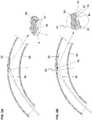
- An embodiment of the catheter tip 20 of the inventionis illustrated in FIGS. 1 and 1A on a balloon-expandable stent delivery system. Depicted in FIG. 1 are a balloon 80, a balloon-expandable stent 85, optional radiopaque markers 15, and the catheter tip 20 including a spring-like element 30. While illustrated here on a balloon-expandable stent system, the catheter tip 20 may be used on any catheter that must navigate tortuous or partially obstructed lumens. As shown in more detail in FIG.
- this embodiment of catheter tip 20 of the inventionincludes a spring-like element 30, such as, in this embodiment, an extension spring.
- the spring-like element 30may have a single diameter from its proximal to distal end, or it may taper towards the distal end.
- the spring-like element 30is positioned distal to the balloon 80. As shown in FIG. 1 , the spring-like element 30 is positioned a distance away from the balloon shoulder, in the distal direction, for example 1 or 2 mm, or in the proximal direction, up to the middle of the balloon or the proximal bond (i.e., juncture between the balloon and the outer tube). Alternatively, the spring-like element is positioned approximately 0.5 mm proximal of the distal edge 45 of the catheter tip 20.
- the portion of the catheter tip 20 that extends distal of the spring-like element 30 to the distal edge 45is the distal end portion 40 of the catheter tip 20.
- the distal end portion 40has sufficient stiffness to provide both pushability and radial rigidity.
- the distal end portion 40may be made of a stiff material such as polyamide.
- the spring-like element 30may extend to the distal edge 45 of the catheter tip 20 and provide radial rigidity to the distal end portion 40 of the catheter tip 20.
- the spring-like element 30may be tapered toward its distal end, but it need not be.
- the catheter tip 20includes a spacer portion 35 that bridges the distance between the distal end of the balloon 80 and the proximal end of the spring-like element 30.
- the spacer portion 35is a longitudinally flexible tube.
- the spacer portion 35is an extension of a flexible tube into which the spring-like element 30 is inserted.
- suitable materials for the flexible tubeinclude a block co-polymer, such as PEBAX, polyurethane, or similar appropriate materials.
- Such a flexible tubemay extend just beyond the distal end of the spring-like element 30, where it is contiguous with the proximal end of the distal end portion 40.
- the distal end portion 40 of the catheter tip 20may be formed from a plastic tube manufactured materials such as Nylon, PEBAX, or various co-polymers. Tapering of the distal end portion 40 may be effected by heating.
- the various tubes and spring membermay be connected by thermal fusing.
- FIG. 2Adepicts how a conventional catheter tip made of a stiff material to achieve good pushability may catch on the rough surface of the lumen of a curved vessel.
- a conventional catheter tip 1Depicted in FIG. 2A is a conventional catheter tip 1; a balloon 80 of a balloon-catheter on which the conventional catheter tip 1 is mounted for illustration; and a guide wire 50.
- the guide wire 50contacts a curved portion of a vessel wall 90, it tends to bend longitudinally as shown in FIG. 2A .
- the conventional catheter tip 1has less longitudinal flexibility than the guide wire 50.
- the distal edge 5 of the conventional stiff catheter tip 1protrudes away from the bent guide wire 50 toward the vessel wall where it can catch on the rough surface 91 of the lumen of the vessel wall 90, making deliverability of the catheter difficult and potentially causing damage to the vessel wall 90.
- the protruding distal edge 5 of such a conventional devicecan catch on struts or other structures of the previously deployed stent.
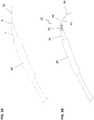
- FIG. 2Billustrates features of an embodiment of the present invention that minimize the risk that the distal edge of the catheter tip will catch on the rough surface of the lumen wall of a curved vessel.
- FIG. 2Bshows a catheter tip 20 made up of two sections - a flexible section with a pushability characteristic, including a spring-like element 30, and a stiff and radially rigid section at the distal end 40, in a curved vessel, and a balloon 80 of a balloon-catheter on which the catheter tip 20 is mounted for illustration.
- the inset of FIG. 2Bshows in greater detail the longitudinal flexibility of the spring-like element 30.
- the longitudinal flexibility of the spring-like element 30permits the catheter tip 20 to flex easily with the guide wire 50 as it flexes laterally with the curve of the vessel lumen, so that the distal end 40 can track tightly with the guide wire 50 and the distal edge 45 does not protrude and catch on the rough surface 91 of the lumen of the vessel wall 90.
- the distal end 40is tapered, as illustrated in the inset of FIG. 2B , which tapering may further reduce the risk that the distal edge 45 will catch on the rough surface 91 of the lumen of the vessel wall 90.
- the spring-like element 20may be covered with or embedded in a layer of a flexible polymer or similar material to create a smooth surface and improve trackability of the structure without altering the flexible properties of the spring.
- materials for such coveringsinclude polyurethane and PEBAX.
- FIG. 3Aillustrates a conventional catheter tip 1 mounted on a balloon-angioplasty system, also showing the balloon 80, and the problem in the art of protrusion of the distal edge 5 of the catheter tip 1.
- the lack of flexibility and the radial rigidity along the length of the conventional catheter tip 1tends to cause the distal edge 5a of the conventional catheter tip 1 to protrude away from the guide wire 50 as it curves through the vessel.
- the large inner diameter and thick walls of the distal end of the conventional catheter tipmay further contribute to the problem of the protruding distal edge.
- FIG. 3Billustrates how the combination of flexibility and radial rigidity of a catheter tip 20 in accordance with the invention minimizes flaring of the distal edge 45 in an embodiment of the catheter tip of the invention (also mounted on a catheter of a balloon-angioplasty system).
- a catheter tip 20including a spacer portion 35, a spring-like element 30, and a distal end 40; the balloon 80 of the balloon-angioplasty system; and a guide wire 50.
- the radial rigidity and the tapered shape of the distal end 40 in combination with the flexibility of the spring-like element 30limits protrusion of the distal edge 45 beyond the guide wire.
- the longitudinal flexibility of the spring-like element 30permits the catheter tip 20 to bend with the guide wire, minimizing force on the distal edge 45 from the guide wire, and the radial rigidity of the distal end 40 minimizes plastic deformation. As shown in FIG. 3B , bending of the guide wire 50 does not result in protrusion of the distal edge 45 of such a catheter tip 20 from the guide wire 50.
- the distal end 40is made of material having sufficient radial rigidity and stiffness to provide pushability.
- radial rigidity of the distal edge 45is provided by the spring-like element 30 itself (not shown).
- the spring-like element 30it is preferable for the spring-like element 30 to extend to the distal edge 45 of the catheter tip 20, or close to the distal edge 45, so as to provide pushability and radial rigidity to the distal end of the catheter tip 20.
- the spring-like element 30is tapered.
- the estimated compromise between rigidity and elasticity maintained by a conventional catheter tipmay result in kinking when the catheter tip encounters a stenotic portion of a vessel, as illustrated in FIG. 4A .
- kinkingmay occur near the distal end of the balloon or any other localized soft or elastic point within the catheter tip.
- a conventional catheter tip on a balloon catheteris shown in FIG. 4A being pushed through a blood vessel 90 having a stenosis 95.
- the balloon 80 for the balloon-angioplasty balloonon which the conventional catheter tip 1 is mounted for illustration, and a guide wire 50.
- the stenotic materialcauses friction or resistance against the catheter tip, causing the conventional catheter tip 1 to give way to the harder material of the vessel plaque, causing it to kink or buckle, as shown in the insert of FIG. 4A .
- the flexible catheter tip of the inventionprovides greater pushability, and it exhibits no kinking because of its flexible body and spacer portion.
- FIG. 4Bwhere an embodiment of the invention mounted on a balloon catheter is shown being pushed through a stenotic vessel. Depicted is a catheter tip including a spring-like element 30, a spacer portion 35, and a distal end; the balloon 80 of a balloon-angioplasty system on which the catheter tip is mounted for illustration; and a guide wire 50. Because the spring-like element 30 provides not only longitudinal flexibility and radial support, but also improved pushability to the catheter tip 20, the friction exerted by the stenosis 95 against the catheter tip of the invention will not cause the catheter tip 20 to kink.
- the spring-like element 30itself provides sufficient pushability to the distal end 40.
- the distal end 40may be made of a sufficiently stiff or thick material to provide pushability, as well as sufficient radial rigidity.
- any structure that has the desired properties of longitudinal flexibility, radial rigidity and pushabilityis suitable as a spring-like element in accordance with the invention.
- a spring-like elementinclude an extension spring.
- Some springs, including for example compression springs,are not preferred as spring-like elements.
- Extension springshave a tightly packed coil that is conducive to flexion along the longitudinal axis, without permitting spring compression or deformation, which could negatively impact the pushability of the catheter or control of the catheter tip when the catheter is pushed.
- Suitable materials for the spring-like elementinclude, for example, stainless steel, cobalt chromium, Nitinol or other appropriate materials that would be apparent to one skilled in the art from the description herein.
- a suitable range for a spring constant for the spring-like elementis 0.3 - 25 gF/mm.
- the spring-like elementis made of a coiled wire - for example, a stainless steel wire.
- the diameter of the wiremay be in the range of 0.04-0.3 mm, preferably, 0.06-0.2 mm.
- the spring-like elementmay be constructed using radiopaque materials to provide the catheter tip with higher radiopacity, thereby allowing improved imaging of the catheter tip.
- catheter tips of the inventionare illustrated and described herein mounted on catheters of balloon-expandable stent systems and balloon angioplasty systems. However, it is contemplated the catheter tips may be used on any intravascular catheters, including for example self-expanding stent systems, intravascular catheters used to deliver other intravascular prosthetic devices, or other therapeutic intravascular catheters.
Landscapes
- Health & Medical Sciences (AREA)
- Life Sciences & Earth Sciences (AREA)
- Biophysics (AREA)
- Pulmonology (AREA)
- Engineering & Computer Science (AREA)
- Anesthesiology (AREA)
- Biomedical Technology (AREA)
- Heart & Thoracic Surgery (AREA)
- Hematology (AREA)
- Animal Behavior & Ethology (AREA)
- General Health & Medical Sciences (AREA)
- Public Health (AREA)
- Veterinary Medicine (AREA)
- Media Introduction/Drainage Providing Device (AREA)
Description
- The present invention relates to an endovascular catheter, in particular a flexible catheter tip for use, for example, for stent delivery and percutaneous angioplasty. The catheter tip of the invention is specially designed to have features especially useful in percutaneous procedures in which the catheter must traverse stenotic blood vessels, tortuous vessels, or vessels containing previously deployed stents.
- In standard stent delivery systems, the proximal portion of the catheter is manufactured from materials that make it relatively stiff or inflexible, which endows the catheter with adequate pushability. By contrast, the distal portion of the catheter is manufactured to be rather flexible to allow adequate deliverability of the stent through tortuous vessels to the desired target.
- In the case of a balloon catheter, the balloon, which is located at the distal portion of the catheter, is delivered in a deflated state, wrapped around the catheter's inner inflation tube and covered by a crimped stent. Distal to the balloon, the catheter tip is usually tapered, wherein the balloon distal shoulder is fused to the catheter's inner inflation tube. The whole catheter is designed to glide on a guide wire, with the catheter tip serving as the leading part of the catheter to, for example, penetrate a lesion, navigate through a curved vessel, or pass through an already deployed stent within the vessel.
- The properties of the catheter tip determine to a large extent whether or not the catheter will catch on the rough surface of the vessel, the surface of vessel lesion or obstruction, or the struts of a previously deployed stent.
- Current catheter tips of stent delivery systems and on angioplasty balloon systems are made of plastic material, are generally tapered, and have a tip shape that is aimed to provide deliverability of the catheter through challenging anatomies. Two parameters may be adjusted to optimize deliverability. The catheter tip may be designed to have longitudinal flexibility to accommodate tortuous vessels, and/or the tip shape and its radial rigidity may be modified to avoid collapse of the distal edge of the tip and/or kinking of the proximal neck of the catheter tip when obstacles are encountered. Optimizing both parameters simultaneously in a catheter tip is problematic, as longitudinal flexibility requires a very thin or flexible material, while pushability and radial rigidity require a thick or stiff material.
- From
US 5 571 073 a catheter tip is known comprising a soft tubular body and a wire coil embedded therein. - There is still a need in the art for an endovascular catheter tip that is longitudinally flexible and pushable and has radial rigidity at its distal end - in particular at the distal edge, to optimize deliverability of the catheter.
- The present invention provides an endovascular catheter tip as defined in
claim 1 and a catheter comprising such a catheter tip as defined in claim 11. Further improvements are subject to the dependent claims. - According to the present invention, a single component, a spring-like structure, provides longitudinal flexibility and pushability to the catheter tip and radial rigidity at the distal end of the catheter tip.
- The catheter tip further includes a longitudinally flexible tube, said spring-like element extends along said longitudinally flexible tube and said spring-like element located at a position inside said longitudinally flexible tube. The longitudinally flexible tube, in conjunction with the spring-like element, confers longitudinal flexibility to the catheter tip.
- The apparatus of the invention may be used, for example, for intravascular delivery of prosthetic devices, such as a stent, or for balloon angioplasty. Where a balloon catheter is used, the catheter tip constitutes the portion of the catheter distal to the balloon. In embodiments where the catheter does not have a balloon mounted on it, for example in biliary stent systems where the catheter itself may be expandable, the catheter tip of the invention may be mounted at the end of the expandable catheter to lead the catheter through the biliary duct. Generally, the catheter tip may extend a few millimeters beyond the distal edge of such a catheter.
- In addition to the advantage of enhanced deliverability parameters, another desirable effect of the catheter tip of the invention is higher radio-opacity, which may provide the operator with valuable feedback regarding position of the catheter tip during insertion of the catheter into the anatomy to be treated.
Figure 1 depicts an embodiment of the catheter tip of the invention that includes a spring-like element, on a stent delivery system.Figure 1A shows the position of the spring-like element on the catheter tip.Figure 2A depicts the conventional catheter tip on a balloon catheter system in a curved vessel.Figure 2B depicts an embodiment of the flexible catheter tip of the invention on a balloon catheter in a curved vessel.Figure 3A depicts tip edge protrusion of a conventional catheter tip.Figure 3B depicts absence of tip edge protrusion of an embodiment of the flexible catheter tip of the invention having a spring-like element and a radially rigid distal end.Figure 4A depicts a conventional catheter tip on a balloon catheter in a stenotic vessel.Figure 4B depicts an embodiment of the flexible, pushable catheter tip of the invention on a balloon catheter system in a stenotic vessel.- In order to enhance deliverability of an endovascular catheter by combining two otherwise contradictory parameters into one catheter tip, the apparatus of the invention provides a catheter tip having longitudinal flexibility, pushability and radial rigidity. In particular, the catheter tip of the invention includes a spring-like element that is not only longitudinally flexible, but also provides pushability to the catheter tip and also has radial rigidity, meaning that it provides radial support to the catheter tip. The catheter tip of the invention also includes a distal end that extends beyond the distal end of the spring-like element. The distal end is made of a material that confers pushability to the tip and has a tapered shape and sufficient radial rigidity to prevent or minimize flaring at the distal edge of the catheter tip, while gliding over a curved guide wire.
- The novel combined features of the present invention permit an operator to guide an endovascular catheter over a guide wire through tortuous vessels, lesioned or stenotic vessels, or stented vessels with minimal risk of having the distal edge of the catheter tip catch on rough surfaces of the lumen wall or a previously implanted stent and also minimize the risk that the flexible catheter tip will buckle or collapse against the resistance of a vessel stenosis or occlusion.
- The apparatus of the invention is discussed and explained below with reference to the accompanying drawings. Note that the drawings are provided as an exemplary understanding of the present invention and to schematically illustrate particular embodiments of the present invention. The skilled artisan will readily recognize other similar examples equally within the scope of the invention. The drawings are not intended to limit the scope of the present invention as defined in the appended claims.
- The catheter tip of the invention includes a spring-like element, which provides not only longitudinal flexibility, but also pushability to the catheter tip. The spring-like element also confers radial rigidity to the catheter tip. An embodiment of the
catheter tip 20 of the invention is illustrated inFIGS. 1 and 1A on a balloon-expandable stent delivery system. Depicted inFIG. 1 are aballoon 80, a balloon-expandable stent 85,optional radiopaque markers 15, and thecatheter tip 20 including a spring-like element 30. While illustrated here on a balloon-expandable stent system, thecatheter tip 20 may be used on any catheter that must navigate tortuous or partially obstructed lumens. As shown in more detail inFIG. 1A , this embodiment ofcatheter tip 20 of the invention includes a spring-like element 30, such as, in this embodiment, an extension spring. The spring-like element 30 may have a single diameter from its proximal to distal end, or it may taper towards the distal end. - As shown in
FIGS. 1 and 1A , where the catheter tip is used on a balloon-expandable stent system, the spring-like element 30 is positioned distal to theballoon 80. As shown inFIG. 1 , the spring-like element 30 is positioned a distance away from the balloon shoulder, in the distal direction, for example 1 or 2 mm, or in the proximal direction, up to the middle of the balloon or the proximal bond (i.e., juncture between the balloon and the outer tube). Alternatively, the spring-like element is positioned approximately 0.5 mm proximal of thedistal edge 45 of thecatheter tip 20. The portion of thecatheter tip 20 that extends distal of the spring-like element 30 to thedistal edge 45 is thedistal end portion 40 of thecatheter tip 20. Thedistal end portion 40 has sufficient stiffness to provide both pushability and radial rigidity. In one embodiment, thedistal end portion 40 may be made of a stiff material such as polyamide. In another embodiment (not shown), the spring-like element 30 may extend to thedistal edge 45 of thecatheter tip 20 and provide radial rigidity to thedistal end portion 40 of thecatheter tip 20. In this other embodiment, the spring-like element 30 may be tapered toward its distal end, but it need not be. - Where the spring-
like element 30 is positioned at a distance from the shoulder of theballoon 80, as illustrated inFIG. 1 , thecatheter tip 20 includes aspacer portion 35 that bridges the distance between the distal end of theballoon 80 and the proximal end of the spring-like element 30. Thespacer portion 35 is a longitudinally flexible tube. Thespacer portion 35 is an extension of a flexible tube into which the spring-like element 30 is inserted. Examples of suitable materials for the flexible tube include a block co-polymer, such as PEBAX, polyurethane, or similar appropriate materials. Such a flexible tube may extend just beyond the distal end of the spring-like element 30, where it is contiguous with the proximal end of thedistal end portion 40. Thedistal end portion 40 of thecatheter tip 20 may be formed from a plastic tube manufactured materials such as Nylon, PEBAX, or various co-polymers. Tapering of thedistal end portion 40 may be effected by heating. The various tubes and spring member may be connected by thermal fusing. FIG. 2A depicts how a conventional catheter tip made of a stiff material to achieve good pushability may catch on the rough surface of the lumen of a curved vessel. Depicted inFIG. 2A is aconventional catheter tip 1; aballoon 80 of a balloon-catheter on which theconventional catheter tip 1 is mounted for illustration; and aguide wire 50. As theguide wire 50 contacts a curved portion of avessel wall 90, it tends to bend longitudinally as shown inFIG. 2A . Theconventional catheter tip 1 has less longitudinal flexibility than theguide wire 50. Thus, as shown in more detail in the inset ofFIG. 2A , thedistal edge 5 of the conventionalstiff catheter tip 1 protrudes away from thebent guide wire 50 toward the vessel wall where it can catch on therough surface 91 of the lumen of thevessel wall 90, making deliverability of the catheter difficult and potentially causing damage to thevessel wall 90. Similarly, where the catheter must traverse a stented vessel, the protrudingdistal edge 5 of such a conventional device can catch on struts or other structures of the previously deployed stent.FIG. 2B , illustrates features of an embodiment of the present invention that minimize the risk that the distal edge of the catheter tip will catch on the rough surface of the lumen wall of a curved vessel. Specifically,FIG. 2B shows acatheter tip 20 made up of two sections - a flexible section with a pushability characteristic, including a spring-like element 30, and a stiff and radially rigid section at thedistal end 40, in a curved vessel, and aballoon 80 of a balloon-catheter on which thecatheter tip 20 is mounted for illustration. The inset ofFIG. 2B shows in greater detail the longitudinal flexibility of the spring-like element 30. The longitudinal flexibility of the spring-like element 30 permits thecatheter tip 20 to flex easily with theguide wire 50 as it flexes laterally with the curve of the vessel lumen, so that thedistal end 40 can track tightly with theguide wire 50 and thedistal edge 45 does not protrude and catch on therough surface 91 of the lumen of thevessel wall 90. In this embodiment, thedistal end 40 is tapered, as illustrated in the inset ofFIG. 2B , which tapering may further reduce the risk that thedistal edge 45 will catch on therough surface 91 of the lumen of thevessel wall 90. In this or any of the other embodiments not forming part of the present invention where the spring-like element 20 is not inserted into a flexible tube, the spring-like element 20 may be covered with or embedded in a layer of a flexible polymer or similar material to create a smooth surface and improve trackability of the structure without altering the flexible properties of the spring. Examples of materials for such coverings include polyurethane and PEBAX.FIG. 3A illustrates aconventional catheter tip 1 mounted on a balloon-angioplasty system, also showing theballoon 80, and the problem in the art of protrusion of thedistal edge 5 of thecatheter tip 1. The lack of flexibility and the radial rigidity along the length of theconventional catheter tip 1 tends to cause the distal edge 5a of theconventional catheter tip 1 to protrude away from theguide wire 50 as it curves through the vessel. The large inner diameter and thick walls of the distal end of the conventional catheter tip may further contribute to the problem of the protruding distal edge.- By contrast,
FIG. 3B illustrates how the combination of flexibility and radial rigidity of acatheter tip 20 in accordance with the invention minimizes flaring of thedistal edge 45 in an embodiment of the catheter tip of the invention (also mounted on a catheter of a balloon-angioplasty system). Depicted inFIG. 3B is acatheter tip 20 including aspacer portion 35, a spring-like element 30, and adistal end 40; theballoon 80 of the balloon-angioplasty system; and aguide wire 50. The radial rigidity and the tapered shape of thedistal end 40 in combination with the flexibility of the spring-like element 30 limits protrusion of thedistal edge 45 beyond the guide wire. The longitudinal flexibility of the spring-like element 30 permits thecatheter tip 20 to bend with the guide wire, minimizing force on thedistal edge 45 from the guide wire, and the radial rigidity of thedistal end 40 minimizes plastic deformation. As shown inFIG. 3B , bending of theguide wire 50 does not result in protrusion of thedistal edge 45 of such acatheter tip 20 from theguide wire 50. In the embodiment illustrated inFIG. 3B , thedistal end 40 is made of material having sufficient radial rigidity and stiffness to provide pushability. In another embodiment, radial rigidity of thedistal edge 45 is provided by the spring-like element 30 itself (not shown). In such embodiments, it is preferable for the spring-like element 30 to extend to thedistal edge 45 of thecatheter tip 20, or close to thedistal edge 45, so as to provide pushability and radial rigidity to the distal end of thecatheter tip 20. Preferably, in this other embodiment the spring-like element 30 is tapered. - The estimated compromise between rigidity and elasticity maintained by a conventional catheter tip may result in kinking when the catheter tip encounters a stenotic portion of a vessel, as illustrated in
FIG. 4A . For example, kinking may occur near the distal end of the balloon or any other localized soft or elastic point within the catheter tip. A conventional catheter tip on a balloon catheter is shown inFIG. 4A being pushed through ablood vessel 90 having astenosis 95. Also depicted is theballoon 80 for the balloon-angioplasty balloon, on which theconventional catheter tip 1 is mounted for illustration, and aguide wire 50. As the conventional catheter tip is advanced through thestenosis 95, the stenotic material causes friction or resistance against the catheter tip, causing theconventional catheter tip 1 to give way to the harder material of the vessel plaque, causing it to kink or buckle, as shown in the insert ofFIG. 4A . This is particularly a problem when stenotic material includes significant calcium deposits, which is not uncommon. - By contrast, the flexible catheter tip of the invention provides greater pushability, and it exhibits no kinking because of its flexible body and spacer portion. This is illustrated in
FIG. 4B , where an embodiment of the invention mounted on a balloon catheter is shown being pushed through a stenotic vessel. Depicted is a catheter tip including a spring-like element 30, aspacer portion 35, and a distal end; theballoon 80 of a balloon-angioplasty system on which the catheter tip is mounted for illustration; and aguide wire 50. Because the spring-like element 30 provides not only longitudinal flexibility and radial support, but also improved pushability to thecatheter tip 20, the friction exerted by thestenosis 95 against the catheter tip of the invention will not cause thecatheter tip 20 to kink. With regard to thedistal end 40 of thecatheter tip 20 of the invention, in this embodiment, the spring-like element 30 itself provides sufficient pushability to thedistal end 40. Additionally, thedistal end 40 may be made of a sufficiently stiff or thick material to provide pushability, as well as sufficient radial rigidity. - Any structure that has the desired properties of longitudinal flexibility, radial rigidity and pushability is suitable as a spring-like element in accordance with the invention. Examples of a spring-like element include an extension spring. Some springs, including for example compression springs, are not preferred as spring-like elements. Extension springs have a tightly packed coil that is conducive to flexion along the longitudinal axis, without permitting spring compression or deformation, which could negatively impact the pushability of the catheter or control of the catheter tip when the catheter is pushed.
- Suitable materials for the spring-like element include, for example, stainless steel, cobalt chromium, Nitinol or other appropriate materials that would be apparent to one skilled in the art from the description herein. A suitable range for a spring constant for the spring-like element is 0.3 - 25 gF/mm. The spring-like element is made of a coiled wire - for example, a stainless steel wire. The diameter of the wire may be in the range of 0.04-0.3 mm, preferably, 0.06-0.2 mm. One skilled in the art would appreciate from these parameters the appropriate wire diameter range for a spring-like element constructed from other materials. The spring-like element may be constructed using radiopaque materials to provide the catheter tip with higher radiopacity, thereby allowing improved imaging of the catheter tip.
- The embodiments of the catheter tips of the invention are illustrated and described herein mounted on catheters of balloon-expandable stent systems and balloon angioplasty systems. However, it is contemplated the catheter tips may be used on any intravascular catheters, including for example self-expanding stent systems, intravascular catheters used to deliver other intravascular prosthetic devices, or other therapeutic intravascular catheters.
- It will be appreciated by persons having ordinary skill in the art that many variations, additions, modifications, and other applications may be made to what has been particularly shown and described herein by way of embodiments, without departing from the scope of the invention. Therefore it is intended that scope of the invention, as defined by the claims below, includes all foreseeable variations, additions, modifications or applications.
Claims (12)
- A flexible and pushable catheter tip (20) having a proximal end and a distal end, comprising:a spring-like element (30) extending toward a distal-most edge (45) of the catheter tip; anda longitudinally flexible tube having a luminal inside and a vessel wall outside, said spring-like element (30) extends along said longitudinally flexible tube, said spring-like element (30) located at a position inside said longitudinally flexible tube,a spacer portion (35) located proximally of said spring-like element (30) wherein said spacer portion (35) is an extension of said longitudinally flexible tube;wherein said spring-like element (30) provides longitudinal flexibility and pushability to said catheter tip (20), andwherein said spring-like element (30) is a single coiled wire.
- The catheter tip (20) of claim 1, wherein said spring-like element (30) is an extension spring.
- The catheter tip (20) of claim 2, wherein said spring-like element (30) is an extension spring having a tightly packed coil.
- The catheter tip (20) of any one of claims 1-3, wherein said spring-like element (30) tapers distally.
- The catheter tip (20) of any one of claims 1 to 4, wherein said spring-like element (30) is at least partially inserted into said spacer portion (35).
- The catheter tip (20) of any of claims 1 to 4, wherein said spacer portion extends to a proximal edge of said spring-like element (30).
- The catheter tip (20) of any one of claims 1-6, wherein the spring-like element (3) extends distal to a distal end of the longitudinally flexible tube.
- The catheter tip (20) of any one of claims 1-7, wherein a radially rigid distal end section (40) extends distal of said spring-like element (30).
- The catheter tip (20) of any one of claims 1-4, wherein said spring-like element (30) extends to the distal-most edge (45) of the catheter tip (20).
- The catheter tip (20) of any one of claims 1-9, wherein said spring-like element (30) does not extend to the distal-most edge (45) of the catheter tip (20), and wherein a distal end of said catheter tip (20) is open.
- A catheter, comprising: a proximal end; a distal end; a balloon (80) having a proximal shoulder and a distal shoulder; and the catheter tip (20) of any one of claims 1-10;
wherein said balloon (80) is mounted on said catheter proximal of said catheter tip (20). - The catheter of claim 11, wherein said catheter tip (20) includes a spacer portion (35) between a proximal edge of said spring-like element (30) and said distal shoulder of said balloon (80).
Priority Applications (1)
| Application Number | Priority Date | Filing Date | Title |
|---|---|---|---|
| EP18150461.4AEP3323464B1 (en) | 2010-02-09 | 2011-02-08 | Catheter tip assembled with a spring |
Applications Claiming Priority (3)
| Application Number | Priority Date | Filing Date | Title |
|---|---|---|---|
| US30268310P | 2010-02-09 | 2010-02-09 | |
| US30327610P | 2010-02-10 | 2010-02-10 | |
| PCT/IB2011/000386WO2011098911A1 (en) | 2010-02-09 | 2011-02-08 | Catheter tip assembled with a spring |
Related Child Applications (2)
| Application Number | Title | Priority Date | Filing Date |
|---|---|---|---|
| EP18150461.4ADivision-IntoEP3323464B1 (en) | 2010-02-09 | 2011-02-08 | Catheter tip assembled with a spring |
| EP18150461.4ADivisionEP3323464B1 (en) | 2010-02-09 | 2011-02-08 | Catheter tip assembled with a spring |
Publications (2)
| Publication Number | Publication Date |
|---|---|
| EP2533839A1 EP2533839A1 (en) | 2012-12-19 |
| EP2533839B1true EP2533839B1 (en) | 2021-05-05 |
Family
ID=44146515
Family Applications (2)
| Application Number | Title | Priority Date | Filing Date |
|---|---|---|---|
| EP18150461.4AActiveEP3323464B1 (en) | 2010-02-09 | 2011-02-08 | Catheter tip assembled with a spring |
| EP11713869.3AActiveEP2533839B1 (en) | 2010-02-09 | 2011-02-08 | Catheter tip assembled with a spring |
Family Applications Before (1)
| Application Number | Title | Priority Date | Filing Date |
|---|---|---|---|
| EP18150461.4AActiveEP3323464B1 (en) | 2010-02-09 | 2011-02-08 | Catheter tip assembled with a spring |
Country Status (9)
| Country | Link |
|---|---|
| US (2) | US10850065B2 (en) |
| EP (2) | EP3323464B1 (en) |
| JP (5) | JP5797207B2 (en) |
| AU (1) | AU2011214064B2 (en) |
| CA (1) | CA2789394C (en) |
| ES (2) | ES2869953T3 (en) |
| IL (1) | IL221218A (en) |
| RU (1) | RU2531345C2 (en) |
| WO (1) | WO2011098911A1 (en) |
Families Citing this family (32)
| Publication number | Priority date | Publication date | Assignee | Title |
|---|---|---|---|---|
| EP1907042B1 (en) | 2005-07-06 | 2009-03-11 | Vascular Pathways Inc. | Intravenous catheter insertion device and method of use |
| EP2150304B1 (en) | 2007-05-07 | 2010-12-01 | Vascular Pathways Inc. | Intravenous catheter insertion and blood sample devices and method of use |
| US20160183963A1 (en)* | 2010-02-09 | 2016-06-30 | Medinol Ltd. | Device for Traversing Vessel Occlusions and Method of Use |
| CA2789394C (en) | 2010-02-09 | 2016-09-13 | Medinol Ltd. | Catheter tip assembled with a spring |
| US10342570B2 (en) | 2014-02-03 | 2019-07-09 | Medinol Ltd. | Device for traversing vessel occlusions and method of use |
| US11925779B2 (en) | 2010-05-14 | 2024-03-12 | C. R. Bard, Inc. | Catheter insertion device including top-mounted advancement components |
| US8932258B2 (en) | 2010-05-14 | 2015-01-13 | C. R. Bard, Inc. | Catheter placement device and method |
| US10384039B2 (en) | 2010-05-14 | 2019-08-20 | C. R. Bard, Inc. | Catheter insertion device including top-mounted advancement components |
| US9872971B2 (en) | 2010-05-14 | 2018-01-23 | C. R. Bard, Inc. | Guidewire extension system for a catheter placement device |
| US9950139B2 (en) | 2010-05-14 | 2018-04-24 | C. R. Bard, Inc. | Catheter placement device including guidewire and catheter control elements |
| US8690833B2 (en) | 2011-01-31 | 2014-04-08 | Vascular Pathways, Inc. | Intravenous catheter and insertion device with reduced blood spatter |
| ES2835652T3 (en) | 2011-02-25 | 2021-06-22 | Bard Inc C R | Medical component insertion device including a retractable needle |
| USD903101S1 (en) | 2011-05-13 | 2020-11-24 | C. R. Bard, Inc. | Catheter |
| WO2014120741A1 (en) | 2013-01-30 | 2014-08-07 | Vascular Pathways, Inc. | Systems and methods for venipuncture and catheter placement |
| CN105979888A (en)* | 2014-02-03 | 2016-09-28 | 美帝诺有限公司 | Improved device for traversing vessel occlusions and method of use |
| US9789283B2 (en) | 2014-02-03 | 2017-10-17 | Medinol Ltd. | Catheter tip assembled with a spring |
| JP6982025B2 (en)* | 2014-02-03 | 2021-12-17 | メディノール リミテッドMedinol Ltd. | Flexible catheter |
| CA2938741C (en)* | 2014-02-03 | 2019-05-14 | Medinol Ltd. | Catheter tip assembled with a spring |
| JP6404584B2 (en)* | 2014-03-26 | 2018-10-10 | オリンパス株式会社 | Stent delivery system |
| WO2016037127A1 (en) | 2014-09-05 | 2016-03-10 | C.R. Bard, Inc. | Catheter insertion device including retractable needle |
| USD903100S1 (en) | 2015-05-01 | 2020-11-24 | C. R. Bard, Inc. | Catheter placement device |
| CN113350614A (en) | 2015-05-15 | 2021-09-07 | C·R·巴德股份有限公司 | Catheter placement device including extendable needle safety feature |
| US10493262B2 (en) | 2016-09-12 | 2019-12-03 | C. R. Bard, Inc. | Blood control for a catheter insertion device |
| EP3585471B1 (en) | 2017-03-01 | 2025-01-01 | C. R. Bard, Inc. | Catheter insertion device |
| JP2019080876A (en)* | 2017-10-31 | 2019-05-30 | テルモ株式会社 | Method for medical treatment |
| ES2980192T3 (en) | 2018-03-07 | 2024-09-30 | Bard Access Systems Inc | Guidewire advancement and blood reflux systems for a medical device insertion system |
| JP7265527B2 (en) | 2018-03-29 | 2023-04-26 | テルモ株式会社 | catheter assembly |
| USD921884S1 (en) | 2018-07-27 | 2021-06-08 | Bard Access Systems, Inc. | Catheter insertion device |
| TR201902674A2 (en)* | 2019-02-22 | 2019-05-21 | Canakkale Onsekiz Mart Ueniversitesi Rektoerluegue | SPRING CLAMPED BLADE ATERECTOMY CATHETER |
| RU2714394C1 (en)* | 2019-04-02 | 2020-02-14 | Евгений Александрович Головин | Connector for retrograde arterial pressure measurement in internal carotid artery |
| CA3151126A1 (en) | 2019-08-19 | 2021-02-25 | Becton, Dickinson And Company | Midline catheter placement device |
| WO2022190700A1 (en)* | 2021-03-09 | 2022-09-15 | テルモ株式会社 | Catheter and method for manufacturing same |
Family Cites Families (122)
| Publication number | Priority date | Publication date | Assignee | Title |
|---|---|---|---|---|
| US1899914A (en) | 1928-02-11 | 1933-02-28 | Enterprise Mfg Co | Click spring for fishing reels |
| US3618613A (en)* | 1969-05-19 | 1971-11-09 | Heyer Schulte Corp | Antithrombotic intravascular catheter reinforced with nonkinking means |
| US3981297A (en) | 1975-03-03 | 1976-09-21 | Sorenson Research Co., Inc. | Gas sampling catheter assembly and method |
| US4044765A (en)* | 1975-12-17 | 1977-08-30 | Medical Evaluation Devices And Instruments Corporation | Flexible tube for intra-venous feeding |
| US4215703A (en) | 1978-08-29 | 1980-08-05 | Willson James K V | Variable stiffness guide wire |
| US4665604A (en)* | 1982-02-16 | 1987-05-19 | Cordis Corporation | Non-fused torque control catheter |
| US4616652A (en)* | 1983-10-19 | 1986-10-14 | Advanced Cardiovascular Systems, Inc. | Dilatation catheter positioning apparatus |
| US4705511A (en)* | 1985-05-13 | 1987-11-10 | Bipore, Inc. | Introducer sheath assembly |
| US5449343A (en)* | 1985-07-30 | 1995-09-12 | Advanced Cardiovascular Systems, Inc. | Steerable dilatation catheter |
| CH667207A5 (en) | 1985-11-21 | 1988-09-30 | Sarcem Sa | REMOTE CONTROL CATHETER WITH MICRO-BALLOON. |
| US4921483A (en)* | 1985-12-19 | 1990-05-01 | Leocor, Inc. | Angioplasty catheter |
| SU1500313A1 (en)* | 1986-04-08 | 1989-08-15 | Polevik Spartak S | Catheter |
| JPS638304A (en) | 1986-06-30 | 1988-01-14 | Kumiai Chem Ind Co Ltd | Flowering promoter |
| SU1528505A1 (en) | 1986-08-05 | 1989-12-15 | Севастопольская 1-Я Городская Больница Им.Н.И.Пирогова | Urethral catheter |
| US4846174A (en)* | 1986-08-08 | 1989-07-11 | Scimed Life Systems, Inc. | Angioplasty dilating guide wire |
| US4976720A (en)* | 1987-01-06 | 1990-12-11 | Advanced Cardiovascular Systems, Inc. | Vascular catheters |
| US4793350A (en)* | 1987-01-06 | 1988-12-27 | Advanced Cardiovascular Systems, Inc. | Liquid filled low profile dilatation catheter |
| US4927413A (en)* | 1987-08-24 | 1990-05-22 | Progressive Angioplasty Systems, Inc. | Catheter for balloon angioplasty |
| JP2767424B2 (en)* | 1987-10-02 | 1998-06-18 | テルモ株式会社 | catheter |
| JP2535565B2 (en) | 1987-10-30 | 1996-09-18 | 富士通株式会社 | Semiconductor device |
| JPH0412992Y2 (en)* | 1987-12-25 | 1992-03-27 | ||
| US6071273A (en)* | 1988-02-29 | 2000-06-06 | Scimed Life Systems, Inc. | Fixed wire dilatation balloon catheter |
| US4838268A (en)* | 1988-03-07 | 1989-06-13 | Scimed Life Systems, Inc. | Non-over-the wire balloon catheter |
| US4985022A (en)* | 1988-11-23 | 1991-01-15 | Med Institute, Inc. | Catheter having durable and flexible segments |
| US5308324A (en) | 1989-01-09 | 1994-05-03 | Pilot Cardiovascular Systems, Inc. | Steerable medical device |
| US5112304A (en)* | 1989-03-17 | 1992-05-12 | Angeion Corporation | Balloon catheter |
| US5344395A (en) | 1989-11-13 | 1994-09-06 | Scimed Life Systems, Inc. | Apparatus for intravascular cavitation or delivery of low frequency mechanical energy |
| IL93141A0 (en) | 1990-01-23 | 1990-11-05 | Urcan Medical Ltd | Ultrasonic recanalization system |
| WO1991013649A1 (en)* | 1990-03-16 | 1991-09-19 | Medtronic, Inc. | Dilatation catheter |
| US5195954A (en) | 1990-06-26 | 1993-03-23 | Schnepp Pesch Wolfram | Apparatus for the removal of deposits in vessels and organs of animals |
| US5279596A (en)* | 1990-07-27 | 1994-01-18 | Cordis Corporation | Intravascular catheter with kink resistant tip |
| DE4036570A1 (en) | 1990-11-16 | 1992-05-21 | Osypka Peter | CATHETER FOR REDUCING OR REMOVING CONSTRUCTIONS IN VESSELS |
| EP0492361B1 (en)* | 1990-12-21 | 1996-07-31 | Advanced Cardiovascular Systems, Inc. | Fixed-wire dilatation catheter with rotatable balloon assembly |
| CA2117088A1 (en)* | 1991-09-05 | 1993-03-18 | David R. Holmes | Flexible tubular device for use in medical applications |
| IL104028A (en) | 1991-12-16 | 1996-06-18 | Psi Medical Products Inc | Device for impacting a formation in a body passage |
| US5256145A (en) | 1992-03-17 | 1993-10-26 | Scimed Life Systems, Inc. | Dilatation catheter strain relief assembly |
| US5423755A (en) | 1992-08-26 | 1995-06-13 | Advanced Cardiovascular Systems, Inc. | Catheter for prostatic urethral dilatation |
| US5243997A (en) | 1992-09-14 | 1993-09-14 | Interventional Technologies, Inc. | Vibrating device for a guide wire |
| EP0746373A1 (en) | 1992-12-01 | 1996-12-11 | Intelliwire, Inc. | Vibratory element for crossing stenoses |
| US5378234A (en)* | 1993-03-15 | 1995-01-03 | Pilot Cardiovascular Systems, Inc. | Coil polymer composite |
| US5409470A (en)* | 1993-05-07 | 1995-04-25 | C. R. Bard, Inc. | Dilatation catheter and guidewire with threaded tip connection |
| US5458585A (en) | 1993-07-28 | 1995-10-17 | Cardiovascular Imaging Systems, Inc. | Tracking tip for a work element in a catheter system |
| US5571073A (en)* | 1994-01-28 | 1996-11-05 | Cordis Corporation | Catheter flexible tip assembly |
| JP3638304B2 (en)* | 1994-02-25 | 2005-04-13 | シメッド ライフ システムズ インコーポレイテッド | Intravascular catheter |
| US5607407A (en)* | 1994-05-09 | 1997-03-04 | Tolkoff; Marc J. | Catheter assembly |
| US5496294A (en)* | 1994-07-08 | 1996-03-05 | Target Therapeutics, Inc. | Catheter with kink-resistant distal tip |
| US5549119A (en) | 1994-09-13 | 1996-08-27 | Cordis Corporation | Vibrating tip catheter |
| AU4242996A (en)* | 1994-11-23 | 1996-06-17 | Navarre Biomedical, Ltd. | Flexible catheter |
| US5569197A (en)* | 1994-12-21 | 1996-10-29 | Schneider (Usa) Inc | Drug delivery guidewire |
| US5549580A (en)* | 1995-01-23 | 1996-08-27 | Cordis Corporation | Catheter having a flexible distal tip and method of manufacturing |
| US6235007B1 (en)* | 1995-11-27 | 2001-05-22 | Therox, Inc. | Atraumatic fluid delivery devices |
| US5725494A (en) | 1995-11-30 | 1998-03-10 | Pharmasonics, Inc. | Apparatus and methods for ultrasonically enhanced intraluminal therapy |
| US5906606A (en) | 1995-12-04 | 1999-05-25 | Target Therapuetics, Inc. | Braided body balloon catheter |
| US5695506A (en)* | 1996-02-06 | 1997-12-09 | Devices For Vascular Intervention | Catheter device with a flexible housing |
| IL127138A0 (en)* | 1996-05-20 | 1999-09-22 | Percusurge Inc | Catheter balloon core wire |
| US20050245894A1 (en) | 1996-05-20 | 2005-11-03 | Medtronic Vascular, Inc. | Methods and apparatuses for drug delivery to an intravascular occlusion |
| US5833631A (en)* | 1996-06-28 | 1998-11-10 | Target Therapeutics, Inc. | Fiber tip guidewire |
| US5865767A (en) | 1996-07-10 | 1999-02-02 | Cordis Corporation | Guidewire having compound taper |
| US5972019A (en) | 1996-07-25 | 1999-10-26 | Target Therapeutics, Inc. | Mechanical clot treatment device |
| US6069965A (en) | 1996-10-09 | 2000-05-30 | Matsushita Electric Industrial Co., Ltd. | Loudspeaker |
| US6554795B2 (en) | 1997-03-06 | 2003-04-29 | Medtronic Ave, Inc. | Balloon catheter and method of manufacture |
| US5989208A (en) | 1997-05-16 | 1999-11-23 | Nita; Henry | Therapeutic ultrasound system |
| US6179832B1 (en) | 1997-09-11 | 2001-01-30 | Vnus Medical Technologies, Inc. | Expandable catheter having two sets of electrodes |
| US6306105B1 (en) | 1998-05-14 | 2001-10-23 | Scimed Life Systems, Inc. | High performance coil wire |
| US6440120B1 (en)* | 1998-09-02 | 2002-08-27 | Embol-X, Inc. | Bendable shape-retaining cannula |
| EP1150612B1 (en) | 1999-02-02 | 2009-03-11 | Samuel Shiber | Flexible-agitator system |
| US6855123B2 (en) | 2002-08-02 | 2005-02-15 | Flow Cardia, Inc. | Therapeutic ultrasound system |
| US6500147B2 (en)* | 1999-02-22 | 2002-12-31 | Medtronic Percusurge, Inc. | Flexible catheter |
| US6398791B1 (en)* | 1999-06-11 | 2002-06-04 | Scimed Life Systems Inc | Variable composite sheath with interrupted sections |
| US6238392B1 (en) | 1999-06-29 | 2001-05-29 | Ethicon Endo-Surgery, Inc. | Bipolar electrosurgical instrument including a plurality of balloon electrodes |
| AU5629300A (en)* | 1999-07-29 | 2001-02-19 | Scope Medical, Inc. | Steerable medical device |
| JP2001129002A (en) | 1999-11-02 | 2001-05-15 | Olympus Optical Co Ltd | Bone prosthesis pushing-in tool |
| US6589253B1 (en) | 1999-12-30 | 2003-07-08 | Advanced Cardiovascular Systems, Inc. | Ultrasonic angioplasty transmission wire |
| US6322586B1 (en) | 2000-01-10 | 2001-11-27 | Scimed Life Systems, Inc. | Catheter tip designs and method of manufacture |
| EP1409058A2 (en) | 2000-01-28 | 2004-04-21 | William Cook Europe ApS | Endovascular medical device with plurality of wires |
| JP3519656B2 (en)* | 2000-01-31 | 2004-04-19 | 株式会社シーアイメディック | Medical guidewire and balloon catheter |
| JP2004510524A (en)* | 2000-10-12 | 2004-04-08 | メドトロニック バスキュラー インコーポレイテッド | Method and apparatus for protecting a proximal end of a medical device |
| EP1337183B1 (en) | 2000-11-24 | 2005-05-25 | Innovacell Biotechnologie GmbH | Ultrasonic probe comprising a positioning device for examination devices and operation devices |
| US6623504B2 (en) | 2000-12-08 | 2003-09-23 | Scimed Life Systems, Inc. | Balloon catheter with radiopaque distal tip |
| US8721625B2 (en)* | 2001-01-26 | 2014-05-13 | Cook Medical Technologies Llc | Endovascular medical device with plurality of wires |
| JP4827301B2 (en) | 2001-02-05 | 2011-11-30 | Hoya株式会社 | Endoscopic catheter |
| US6695793B2 (en)* | 2001-07-31 | 2004-02-24 | Cardiac Pacemakers, Inc. | Guide catheter for placing cardiac lead |
| US7351214B2 (en)* | 2002-03-22 | 2008-04-01 | Cordis Corporation | Steerable balloon catheter |
| US6855136B2 (en)* | 2002-04-03 | 2005-02-15 | Gore Enterprise Holdings, Inc. | Infusion catheter having an atraumatic tip |
| US7058456B2 (en) | 2002-08-09 | 2006-06-06 | Concentric Medical, Inc. | Methods and devices for changing the shape of a medical device |
| WO2004045387A2 (en)* | 2002-11-18 | 2004-06-03 | Stereotaxis, Inc. | Magnetically navigable balloon catheters |
| JP3971320B2 (en)* | 2003-02-17 | 2007-09-05 | 修 加藤 | catheter |
| US9254213B2 (en) | 2004-01-09 | 2016-02-09 | Rubicon Medical, Inc. | Stent delivery device |
| US8535293B2 (en) | 2004-04-13 | 2013-09-17 | Gyrus Acmi, Inc. | Atraumatic ureteral access sheath |
| US7720521B2 (en)* | 2004-04-21 | 2010-05-18 | Acclarent, Inc. | Methods and devices for performing procedures within the ear, nose, throat and paranasal sinuses |
| JP4429070B2 (en)* | 2004-05-11 | 2010-03-10 | テルモ株式会社 | Catheter with good controllability for needle stick amount |
| CN101001658A (en) | 2004-08-10 | 2007-07-18 | 株式会社钟化 | Catheter tube for medical treatment and method of manufacturing the same |
| WO2006042157A1 (en)* | 2004-10-06 | 2006-04-20 | Cook Incorporated | A flexible tip |
| RU2302267C2 (en) | 2004-11-11 | 2007-07-10 | Государственное учреждение САРАТОВСКИЙ НАУЧНО-ИССЛЕДОВАТЕЛЬСКИЙ ИНСТИТУТ КАРДИОЛОГИИ МИНИСТЕРСТВА ЗДРАВООХРАНЕНИЯ РОССИЙСКОЙ ФЕДЕРАЦИИ | Method for removing occlusion of coronary artery |
| JP4693091B2 (en) | 2004-12-21 | 2011-06-01 | 朝日インテック株式会社 | Catheter and manufacturing method thereof |
| JP5027651B2 (en) | 2005-03-03 | 2012-09-19 | 株式会社グツドマン | Vascular catheter |
| JP2006271901A (en) | 2005-03-30 | 2006-10-12 | Nippon Zeon Co Ltd | Coiled contrast marker, method for manufacturing the same, and catheter |
| CN101926667B (en) | 2005-05-25 | 2012-12-05 | 泰科保健集团有限合伙公司 | System and method for conveying and unfolding stopper in blood vessel |
| CA2630215A1 (en) | 2005-11-17 | 2007-05-24 | Micromuscle Ab | Medical devices and methods for their fabrication and use |
| US20070260224A1 (en)* | 2006-03-09 | 2007-11-08 | Abbott Laboratories | Flexible catheter tip having a shaped head |
| US7678223B2 (en) | 2006-04-17 | 2010-03-16 | Boston Scientific Scimed, Inc. | Catheter having a multi-section tubular member and method of making the same |
| EE200600030A (en) | 2006-08-15 | 2008-04-15 | Tartu �likool | Protein kinase fluorescence probe |
| US20080108974A1 (en)* | 2006-10-20 | 2008-05-08 | Vital Signs, Inc. | Reinforced catheter with radiopaque distal tip and process of manufacture |
| FI122703B (en) | 2006-12-14 | 2012-05-31 | Foster Wheeler Energia Oy | Shaking device for a surface that is soiled |
| CA2845188A1 (en) | 2007-10-29 | 2009-05-07 | Schwager Medica Ag | Catheter |
| US8034075B2 (en) | 2007-11-09 | 2011-10-11 | Micrus Endovascular Corporation | Tethered coil for treatment of body lumens |
| JP2011512956A (en) | 2008-02-26 | 2011-04-28 | ボストン サイエンティフィック サイムド,インコーポレイテッド | Balloon catheter with a highly durable tip |
| WO2009132072A2 (en) | 2008-04-22 | 2009-10-29 | Ethicon Endo-Surgery, Inc. | Methods and devices for dissecting tissue |
| WO2009141810A2 (en) | 2008-05-23 | 2009-11-26 | Oscillon Ltd | Method and device for recanalization of total occlusions |
| JP4267055B1 (en) | 2008-07-18 | 2009-05-27 | 規方 田熊 | Suction catheter and suction catheter system |
| US20100049167A1 (en) | 2008-08-20 | 2010-02-25 | Cook Incorporated | Introducer sheath having reinforced distal taper |
| WO2011005957A1 (en) | 2009-07-09 | 2011-01-13 | Cook Incorporated | Spring action wire guide |
| WO2011005971A1 (en) | 2009-07-09 | 2011-01-13 | Cook Incorporated | Spring action medical device |
| WO2011008896A2 (en) | 2009-07-14 | 2011-01-20 | Board Of Regents, The University Of Texas System | Therapeutic methods using controlled delivery devices having zero order kinetics |
| RU91674U1 (en) | 2009-09-07 | 2010-02-27 | Александр Григорьевич Осиев | INTRACORONARY CONDUCTOR (OPTIONS) |
| JP5508804B2 (en) | 2009-10-06 | 2014-06-04 | オリンパス株式会社 | Guide device |
| EP3508244A1 (en) | 2010-02-09 | 2019-07-10 | Medinol Ltd. | System for traversing vessel occlusions |
| CA2789394C (en) | 2010-02-09 | 2016-09-13 | Medinol Ltd. | Catheter tip assembled with a spring |
| JP4896245B2 (en) | 2010-03-31 | 2012-03-14 | 朝日インテック株式会社 | Guide wire |
| US20110245775A1 (en) | 2010-04-01 | 2011-10-06 | Cook Incorporated | Tapered sheath |
| US8034045B1 (en) | 2010-05-05 | 2011-10-11 | Cook Medical Technologies Llc | Flexible sheath |
| JP5382881B2 (en) | 2011-06-15 | 2014-01-08 | 朝日インテック株式会社 | Guide wire |
- 2011
- 2011-02-08CACA2789394Apatent/CA2789394C/ennot_activeExpired - Fee Related
- 2011-02-08EPEP18150461.4Apatent/EP3323464B1/enactiveActive
- 2011-02-08USUS13/022,749patent/US10850065B2/enactiveActive
- 2011-02-08JPJP2012552487Apatent/JP5797207B2/enactiveActive
- 2011-02-08ESES11713869Tpatent/ES2869953T3/enactiveActive
- 2011-02-08WOPCT/IB2011/000386patent/WO2011098911A1/enactiveApplication Filing
- 2011-02-08ESES18150461Tpatent/ES2986380T3/enactiveActive
- 2011-02-08AUAU2011214064Apatent/AU2011214064B2/ennot_activeCeased
- 2011-02-08RURU2012132248/14Apatent/RU2531345C2/enactive
- 2011-02-08EPEP11713869.3Apatent/EP2533839B1/enactiveActive
- 2012
- 2012-07-31ILIL221218Apatent/IL221218A/enactiveIP Right Grant
- 2015
- 2015-08-18JPJP2015160792Apatent/JP6273613B2/enactiveActive
- 2017
- 2017-09-11JPJP2017173800Apatent/JP2018000988A/enactivePending
- 2019
- 2019-07-19JPJP2019133725Apatent/JP6955314B2/enactiveActive
- 2020
- 2020-10-20USUS17/075,348patent/US20210031003A1/enactivePending
- 2021
- 2021-06-24JPJP2021104644Apatent/JP2021166733A/enactivePending
Also Published As
| Publication number | Publication date |
|---|---|
| US20210031003A1 (en) | 2021-02-04 |
| RU2531345C2 (en) | 2014-10-20 |
| JP6955314B2 (en) | 2021-10-27 |
| JP2013518691A (en) | 2013-05-23 |
| US10850065B2 (en) | 2020-12-01 |
| CA2789394C (en) | 2016-09-13 |
| AU2011214064B2 (en) | 2014-04-24 |
| JP5797207B2 (en) | 2015-10-21 |
| CA2789394A1 (en) | 2011-08-18 |
| JP2019195677A (en) | 2019-11-14 |
| US20110196315A1 (en) | 2011-08-11 |
| JP2015205218A (en) | 2015-11-19 |
| IL221218A (en) | 2015-06-30 |
| JP2018000988A (en) | 2018-01-11 |
| ES2869953T3 (en) | 2021-10-26 |
| RU2012132248A (en) | 2014-03-20 |
| IL221218A0 (en) | 2012-10-31 |
| EP3323464A1 (en) | 2018-05-23 |
| EP3323464B1 (en) | 2024-07-31 |
| HK1248154A1 (en) | 2018-10-12 |
| JP6273613B2 (en) | 2018-02-07 |
| AU2011214064A1 (en) | 2012-08-16 |
| WO2011098911A1 (en) | 2011-08-18 |
| JP2021166733A (en) | 2021-10-21 |
| ES2986380T3 (en) | 2024-11-11 |
| EP2533839A1 (en) | 2012-12-19 |
Similar Documents
| Publication | Publication Date | Title |
|---|---|---|
| US20210031003A1 (en) | Catheter tip assembled with a spring | |
| US11458284B2 (en) | Catheter tip assembled with a spring | |
| CA2938741C (en) | Catheter tip assembled with a spring | |
| HK1173401B (en) | Catheter tip assembled with a spring | |
| HK1173401A (en) | Catheter tip assembled with a spring | |
| HK1248154B (en) | Catheter tip assembled with a spring | |
| HK1227780B (en) | Catheter tip assembled with a spring | |
| HK1227780A1 (en) | Catheter tip assembled with a spring | |
| JP6982025B2 (en) | Flexible catheter |
Legal Events
| Date | Code | Title | Description |
|---|---|---|---|
| PUAI | Public reference made under article 153(3) epc to a published international application that has entered the european phase | Free format text:ORIGINAL CODE: 0009012 | |
| 17P | Request for examination filed | Effective date:20120824 | |
| AK | Designated contracting states | Kind code of ref document:A1 Designated state(s):AL AT BE BG CH CY CZ DE DK EE ES FI FR GB GR HR HU IE IS IT LI LT LU LV MC MK MT NL NO PL PT RO RS SE SI SK SM TR | |
| DAX | Request for extension of the european patent (deleted) | ||
| REG | Reference to a national code | Ref country code:HK Ref legal event code:DE Ref document number:1173401 Country of ref document:HK | |
| RAP1 | Party data changed (applicant data changed or rights of an application transferred) | Owner name:MEDINOL LTD. | |
| 17Q | First examination report despatched | Effective date:20140403 | |
| RAP1 | Party data changed (applicant data changed or rights of an application transferred) | Owner name:MEDINOL LTD. | |
| STAA | Information on the status of an ep patent application or granted ep patent | Free format text:STATUS: EXAMINATION IS IN PROGRESS | |
| GRAP | Despatch of communication of intention to grant a patent | Free format text:ORIGINAL CODE: EPIDOSNIGR1 | |
| STAA | Information on the status of an ep patent application or granted ep patent | Free format text:STATUS: GRANT OF PATENT IS INTENDED | |
| INTG | Intention to grant announced | Effective date:20201120 | |
| GRAS | Grant fee paid | Free format text:ORIGINAL CODE: EPIDOSNIGR3 | |
| GRAA | (expected) grant | Free format text:ORIGINAL CODE: 0009210 | |
| STAA | Information on the status of an ep patent application or granted ep patent | Free format text:STATUS: THE PATENT HAS BEEN GRANTED | |
| AK | Designated contracting states | Kind code of ref document:B1 Designated state(s):AL AT BE BG CH CY CZ DE DK EE ES FI FR GB GR HR HU IE IS IT LI LT LU LV MC MK MT NL NO PL PT RO RS SE SI SK SM TR | |
| REG | Reference to a national code | Ref country code:GB Ref legal event code:FG4D | |
| REG | Reference to a national code | Ref country code:CH Ref legal event code:EP | |
| REG | Reference to a national code | Ref country code:AT Ref legal event code:REF Ref document number:1389028 Country of ref document:AT Kind code of ref document:T Effective date:20210515 | |
| REG | Reference to a national code | Ref country code:IE Ref legal event code:FG4D | |
| REG | Reference to a national code | Ref country code:DE Ref legal event code:R096 Ref document number:602011070868 Country of ref document:DE | |
| REG | Reference to a national code | Ref country code:NL Ref legal event code:FP | |
| REG | Reference to a national code | Ref country code:LT Ref legal event code:MG9D | |
| REG | Reference to a national code | Ref country code:AT Ref legal event code:MK05 Ref document number:1389028 Country of ref document:AT Kind code of ref document:T Effective date:20210505 | |
| REG | Reference to a national code | Ref country code:ES Ref legal event code:FG2A Ref document number:2869953 Country of ref document:ES Kind code of ref document:T3 Effective date:20211026 | |
| PG25 | Lapsed in a contracting state [announced via postgrant information from national office to epo] | Ref country code:AT Free format text:LAPSE BECAUSE OF FAILURE TO SUBMIT A TRANSLATION OF THE DESCRIPTION OR TO PAY THE FEE WITHIN THE PRESCRIBED TIME-LIMIT Effective date:20210505 Ref country code:BG Free format text:LAPSE BECAUSE OF FAILURE TO SUBMIT A TRANSLATION OF THE DESCRIPTION OR TO PAY THE FEE WITHIN THE PRESCRIBED TIME-LIMIT Effective date:20210805 Ref country code:HR Free format text:LAPSE BECAUSE OF FAILURE TO SUBMIT A TRANSLATION OF THE DESCRIPTION OR TO PAY THE FEE WITHIN THE PRESCRIBED TIME-LIMIT Effective date:20210505 Ref country code:FI Free format text:LAPSE BECAUSE OF FAILURE TO SUBMIT A TRANSLATION OF THE DESCRIPTION OR TO PAY THE FEE WITHIN THE PRESCRIBED TIME-LIMIT Effective date:20210505 Ref country code:LT Free format text:LAPSE BECAUSE OF FAILURE TO SUBMIT A TRANSLATION OF THE DESCRIPTION OR TO PAY THE FEE WITHIN THE PRESCRIBED TIME-LIMIT Effective date:20210505 | |
| PG25 | Lapsed in a contracting state [announced via postgrant information from national office to epo] | Ref country code:LV Free format text:LAPSE BECAUSE OF FAILURE TO SUBMIT A TRANSLATION OF THE DESCRIPTION OR TO PAY THE FEE WITHIN THE PRESCRIBED TIME-LIMIT Effective date:20210505 Ref country code:IS Free format text:LAPSE BECAUSE OF FAILURE TO SUBMIT A TRANSLATION OF THE DESCRIPTION OR TO PAY THE FEE WITHIN THE PRESCRIBED TIME-LIMIT Effective date:20210905 Ref country code:GR Free format text:LAPSE BECAUSE OF FAILURE TO SUBMIT A TRANSLATION OF THE DESCRIPTION OR TO PAY THE FEE WITHIN THE PRESCRIBED TIME-LIMIT Effective date:20210806 Ref country code:RS Free format text:LAPSE BECAUSE OF FAILURE TO SUBMIT A TRANSLATION OF THE DESCRIPTION OR TO PAY THE FEE WITHIN THE PRESCRIBED TIME-LIMIT Effective date:20210505 Ref country code:SE Free format text:LAPSE BECAUSE OF FAILURE TO SUBMIT A TRANSLATION OF THE DESCRIPTION OR TO PAY THE FEE WITHIN THE PRESCRIBED TIME-LIMIT Effective date:20210505 Ref country code:PL Free format text:LAPSE BECAUSE OF FAILURE TO SUBMIT A TRANSLATION OF THE DESCRIPTION OR TO PAY THE FEE WITHIN THE PRESCRIBED TIME-LIMIT Effective date:20210505 Ref country code:PT Free format text:LAPSE BECAUSE OF FAILURE TO SUBMIT A TRANSLATION OF THE DESCRIPTION OR TO PAY THE FEE WITHIN THE PRESCRIBED TIME-LIMIT Effective date:20210906 Ref country code:NO Free format text:LAPSE BECAUSE OF FAILURE TO SUBMIT A TRANSLATION OF THE DESCRIPTION OR TO PAY THE FEE WITHIN THE PRESCRIBED TIME-LIMIT Effective date:20210805 | |
| PG25 | Lapsed in a contracting state [announced via postgrant information from national office to epo] | Ref country code:RO Free format text:LAPSE BECAUSE OF FAILURE TO SUBMIT A TRANSLATION OF THE DESCRIPTION OR TO PAY THE FEE WITHIN THE PRESCRIBED TIME-LIMIT Effective date:20210505 Ref country code:SM Free format text:LAPSE BECAUSE OF FAILURE TO SUBMIT A TRANSLATION OF THE DESCRIPTION OR TO PAY THE FEE WITHIN THE PRESCRIBED TIME-LIMIT Effective date:20210505 Ref country code:SK Free format text:LAPSE BECAUSE OF FAILURE TO SUBMIT A TRANSLATION OF THE DESCRIPTION OR TO PAY THE FEE WITHIN THE PRESCRIBED TIME-LIMIT Effective date:20210505 Ref country code:EE Free format text:LAPSE BECAUSE OF FAILURE TO SUBMIT A TRANSLATION OF THE DESCRIPTION OR TO PAY THE FEE WITHIN THE PRESCRIBED TIME-LIMIT Effective date:20210505 Ref country code:DK Free format text:LAPSE BECAUSE OF FAILURE TO SUBMIT A TRANSLATION OF THE DESCRIPTION OR TO PAY THE FEE WITHIN THE PRESCRIBED TIME-LIMIT Effective date:20210505 Ref country code:CZ Free format text:LAPSE BECAUSE OF FAILURE TO SUBMIT A TRANSLATION OF THE DESCRIPTION OR TO PAY THE FEE WITHIN THE PRESCRIBED TIME-LIMIT Effective date:20210505 | |
| REG | Reference to a national code | Ref country code:DE Ref legal event code:R097 Ref document number:602011070868 Country of ref document:DE | |
| PLBE | No opposition filed within time limit | Free format text:ORIGINAL CODE: 0009261 | |
| STAA | Information on the status of an ep patent application or granted ep patent | Free format text:STATUS: NO OPPOSITION FILED WITHIN TIME LIMIT | |
| 26N | No opposition filed | Effective date:20220208 | |
| PG25 | Lapsed in a contracting state [announced via postgrant information from national office to epo] | Ref country code:IS Free format text:LAPSE BECAUSE OF FAILURE TO SUBMIT A TRANSLATION OF THE DESCRIPTION OR TO PAY THE FEE WITHIN THE PRESCRIBED TIME-LIMIT Effective date:20210905 Ref country code:AL Free format text:LAPSE BECAUSE OF FAILURE TO SUBMIT A TRANSLATION OF THE DESCRIPTION OR TO PAY THE FEE WITHIN THE PRESCRIBED TIME-LIMIT Effective date:20210505 | |
| REG | Reference to a national code | Ref country code:DE Ref legal event code:R119 Ref document number:602011070868 Country of ref document:DE | |
| PG25 | Lapsed in a contracting state [announced via postgrant information from national office to epo] | Ref country code:MC Free format text:LAPSE BECAUSE OF FAILURE TO SUBMIT A TRANSLATION OF THE DESCRIPTION OR TO PAY THE FEE WITHIN THE PRESCRIBED TIME-LIMIT Effective date:20210505 | |
| REG | Reference to a national code | Ref country code:CH Ref legal event code:PL | |
| REG | Reference to a national code | Ref country code:BE Ref legal event code:MM Effective date:20220228 | |
| PG25 | Lapsed in a contracting state [announced via postgrant information from national office to epo] | Ref country code:LU Free format text:LAPSE BECAUSE OF NON-PAYMENT OF DUE FEES Effective date:20220208 | |
| PG25 | Lapsed in a contracting state [announced via postgrant information from national office to epo] | Ref country code:LI Free format text:LAPSE BECAUSE OF NON-PAYMENT OF DUE FEES Effective date:20220228 Ref country code:DE Free format text:LAPSE BECAUSE OF NON-PAYMENT OF DUE FEES Effective date:20220901 Ref country code:CH Free format text:LAPSE BECAUSE OF NON-PAYMENT OF DUE FEES Effective date:20220228 | |
| PG25 | Lapsed in a contracting state [announced via postgrant information from national office to epo] | Ref country code:BE Free format text:LAPSE BECAUSE OF NON-PAYMENT OF DUE FEES Effective date:20220228 | |
| P01 | Opt-out of the competence of the unified patent court (upc) registered | Effective date:20230510 | |
| PG25 | Lapsed in a contracting state [announced via postgrant information from national office to epo] | Ref country code:HU Free format text:LAPSE BECAUSE OF FAILURE TO SUBMIT A TRANSLATION OF THE DESCRIPTION OR TO PAY THE FEE WITHIN THE PRESCRIBED TIME-LIMIT; INVALID AB INITIO Effective date:20110208 | |
| PG25 | Lapsed in a contracting state [announced via postgrant information from national office to epo] | Ref country code:MK Free format text:LAPSE BECAUSE OF FAILURE TO SUBMIT A TRANSLATION OF THE DESCRIPTION OR TO PAY THE FEE WITHIN THE PRESCRIBED TIME-LIMIT Effective date:20210505 Ref country code:CY Free format text:LAPSE BECAUSE OF FAILURE TO SUBMIT A TRANSLATION OF THE DESCRIPTION OR TO PAY THE FEE WITHIN THE PRESCRIBED TIME-LIMIT Effective date:20210505 | |
| PG25 | Lapsed in a contracting state [announced via postgrant information from national office to epo] | Ref country code:TR Free format text:LAPSE BECAUSE OF FAILURE TO SUBMIT A TRANSLATION OF THE DESCRIPTION OR TO PAY THE FEE WITHIN THE PRESCRIBED TIME-LIMIT Effective date:20210505 | |
| PG25 | Lapsed in a contracting state [announced via postgrant information from national office to epo] | Ref country code:MT Free format text:LAPSE BECAUSE OF FAILURE TO SUBMIT A TRANSLATION OF THE DESCRIPTION OR TO PAY THE FEE WITHIN THE PRESCRIBED TIME-LIMIT Effective date:20210505 | |
| PGFP | Annual fee paid to national office [announced via postgrant information from national office to epo] | Ref country code:NL Payment date:20250227 Year of fee payment:15 | |
| PGFP | Annual fee paid to national office [announced via postgrant information from national office to epo] | Ref country code:ES Payment date:20250303 Year of fee payment:15 | |
| PGFP | Annual fee paid to national office [announced via postgrant information from national office to epo] | Ref country code:IE Payment date:20250227 Year of fee payment:15 | |
| PGFP | Annual fee paid to national office [announced via postgrant information from national office to epo] | Ref country code:FR Payment date:20250225 Year of fee payment:15 | |
| PGFP | Annual fee paid to national office [announced via postgrant information from national office to epo] | Ref country code:IT Payment date:20250220 Year of fee payment:15 Ref country code:GB Payment date:20250227 Year of fee payment:15 |