EP2533698B1 - Automatic vascular closure deployment devices - Google Patents
Automatic vascular closure deployment devicesDownload PDFInfo
- Publication number
- EP2533698B1 EP2533698B1EP11706087.1AEP11706087AEP2533698B1EP 2533698 B1EP2533698 B1EP 2533698B1EP 11706087 AEP11706087 AEP 11706087AEP 2533698 B1EP2533698 B1EP 2533698B1
- Authority
- EP
- European Patent Office
- Prior art keywords
- suture
- sheath
- anchor
- housing
- plug
- Prior art date
- Legal status (The legal status is an assumption and is not a legal conclusion. Google has not performed a legal analysis and makes no representation as to the accuracy of the status listed.)
- Not-in-force
Links
Images


Classifications
- A—HUMAN NECESSITIES
- A61—MEDICAL OR VETERINARY SCIENCE; HYGIENE
- A61B—DIAGNOSIS; SURGERY; IDENTIFICATION
- A61B17/00—Surgical instruments, devices or methods
- A61B17/0057—Implements for plugging an opening in the wall of a hollow or tubular organ, e.g. for sealing a vessel puncture or closing a cardiac septal defect
- A—HUMAN NECESSITIES
- A61—MEDICAL OR VETERINARY SCIENCE; HYGIENE
- A61B—DIAGNOSIS; SURGERY; IDENTIFICATION
- A61B17/00—Surgical instruments, devices or methods
- A61B17/04—Surgical instruments, devices or methods for suturing wounds; Holders or packages for needles or suture materials
- A61B17/0467—Instruments for cutting sutures
- A—HUMAN NECESSITIES
- A61—MEDICAL OR VETERINARY SCIENCE; HYGIENE
- A61B—DIAGNOSIS; SURGERY; IDENTIFICATION
- A61B17/00—Surgical instruments, devices or methods
- A61B17/04—Surgical instruments, devices or methods for suturing wounds; Holders or packages for needles or suture materials
- A61B17/0487—Suture clamps, clips or locks, e.g. for replacing suture knots; Instruments for applying or removing suture clamps, clips or locks
- A—HUMAN NECESSITIES
- A61—MEDICAL OR VETERINARY SCIENCE; HYGIENE
- A61B—DIAGNOSIS; SURGERY; IDENTIFICATION
- A61B17/00—Surgical instruments, devices or methods
- A61B17/0057—Implements for plugging an opening in the wall of a hollow or tubular organ, e.g. for sealing a vessel puncture or closing a cardiac septal defect
- A61B2017/00646—Type of implements
- A61B2017/00654—Type of implements entirely comprised between the two sides of the opening
- A—HUMAN NECESSITIES
- A61—MEDICAL OR VETERINARY SCIENCE; HYGIENE
- A61B—DIAGNOSIS; SURGERY; IDENTIFICATION
- A61B17/00—Surgical instruments, devices or methods
- A61B17/0057—Implements for plugging an opening in the wall of a hollow or tubular organ, e.g. for sealing a vessel puncture or closing a cardiac septal defect
- A61B2017/00646—Type of implements
- A61B2017/00663—Type of implements the implement being a suture
- A—HUMAN NECESSITIES
- A61—MEDICAL OR VETERINARY SCIENCE; HYGIENE
- A61B—DIAGNOSIS; SURGERY; IDENTIFICATION
- A61B17/00—Surgical instruments, devices or methods
- A61B17/04—Surgical instruments, devices or methods for suturing wounds; Holders or packages for needles or suture materials
- A61B17/0401—Suture anchors, buttons or pledgets, i.e. means for attaching sutures to bone, cartilage or soft tissue; Instruments for applying or removing suture anchors
- A61B2017/0417—T-fasteners
- A—HUMAN NECESSITIES
- A61—MEDICAL OR VETERINARY SCIENCE; HYGIENE
- A61B—DIAGNOSIS; SURGERY; IDENTIFICATION
- A61B17/00—Surgical instruments, devices or methods
- A61B17/04—Surgical instruments, devices or methods for suturing wounds; Holders or packages for needles or suture materials
- A61B2017/0496—Surgical instruments, devices or methods for suturing wounds; Holders or packages for needles or suture materials for tensioning sutures
- A—HUMAN NECESSITIES
- A61—MEDICAL OR VETERINARY SCIENCE; HYGIENE
- A61B—DIAGNOSIS; SURGERY; IDENTIFICATION
- A61B90/00—Instruments, implements or accessories specially adapted for surgery or diagnosis and not covered by any of the groups A61B1/00 - A61B50/00, e.g. for luxation treatment or for protecting wound edges
- A61B90/08—Accessories or related features not otherwise provided for
- A61B2090/0807—Indication means
Definitions
- the present inventionrelates generally to medical devices for sealing and closing passages formed through tissue. More specifically, the present invention relates to apparatuses or devices for sealing or closing an opening formed through biological tissue to control, prevent or stop bleeding or other biological fluid or tissue.
- an openingcan be created in a blood vessel or arteriotomy to allow for the insertion of various medical devices which can be navigated through the blood vessel to the site to be treated.
- a guidewiremay first be inserted through the tissue tract created between the skin, or the epidermis, of the patient down through the subcutaneous tissue and into the opening formed in the blood vessel. The guidewire is then navigated through the blood vessel to the site of the occlusion or other treatment site. Once the guidewire is in place, an introducer sheath can be slid over the guide wire to form a wider, more easily accessible, tract between the epidermis and the opening into the blood vessel. The appropriate medical device can then be introduced over the guidewire through the introducer sheath and then up the blood vessel to the site of the occlusion or other treatment site.
- the medical devices or other equipment introduced into the vesselcan be retracted through the blood vessel, out the opening in the blood vessel wall, and out through the tissue tract to be removed from the body.
- the physician or other medical technicianis presented with the challenge of trying to close the opening in the blood vessel and/or the tissue tract formed in the epidermis and subcutaneous tissue.
- a number of different device structures, assemblies, and methodsare known for closing the opening in the blood vessel and/or tissue tract, each having certain advantages and disadvantages.
- the primary problemsare that bleeding complications still occur, arterial occlusion problems occur, and there are many steps required to properly implant these devices which require effort by the practitioner, training, and careful attention to various manually-performed steps to reduce the occurrence of complications.
- One step common to most of the prior approacheshas been trimming of the cinching suture at the conclusion of the procedure. This is typically performed by pulling tension on the suture manually, depressing the skin manually, and trimming the suture manually. The suture is trimmed close to the depressed skin so that when the skin is released, the ends of the suture are underneath the surface of the skin. This is important to reduce infections which would be more likely if the suture extends to the skin because this would maintain an access path from outside the body through the normally protective skin layer to the tissues underneath.
- the present inventionovercomes these problems by providing an apparatus which automates the suture cutting, and can easily cut the suture at a location deeper under the skin if desired, providing a faster procedure and an improved safety margin for trimming location.
- WO 99/22646 A1discloses a hemostasis promoting device for sealing an incision or puncture in the body of a patient wherein the closure device includes an anchor member, a sealing member, a filament member and a spring tensioned tamping member wherein the tamping member is arranged to provide a steady pressure to the sealing member to securely and reliably seal the puncture while including various markers thereon to provide the user with visual indications that the closure device is properly deployed in the puncture and blood vessel of the patient to ensure that the patient may be promptly and reliably ambulated within a relatively short period of time once the closure device has been administered to the patient.
- the closure deviceincludes a vessel locating member, an anchor and a sealing material.
- the closure devicemay be configured to deploy the anchor and the sealing material outside of a hole in a blood vessel to close the hole.
- the vessel locating membermay be used to locate the blood vessel to ensure that the anchor and/or the sealing material are properly placed adjacent to the hole.
- the closure devicemay also include a tamper member configured to push or tamp the sealing material against the anchor.
- the closure devicemay also include a suture that is used to hold the sealing material and the anchor together adjacent to the hole in the blood vessel.
- Prior art devicesrequire complex techniques that require many steps to properly implant these devices. This requires training and careful attention to various manually-performed steps to reduce the occurrence of complications.
- the present inventionovercomes these problems by providing an apparatus which automates the implantation procedure, thereby providing more reliable sealing, and reducing the complexity of using the device.
- a devicefor delivering and deploying an anchor, plug, filament and locking mechanism adjacent to the opening in the vessel wall and/or tissue tract.
- the anchormay be automatically seated against the vessel wall.
- the plugis compressed and the filament is trimmed automatically.
- the anchoris seated, the plug is compressed and the filament is trimmed automatically.
- the disclosurepertains to apparatuses and methods for implantation and deployment of an anchor-plug-cinch vascular closure device.
- the implantation and deployment apparatusmay comprise an automated plug deployment mechanism having actuation means, drive mechanism, automatic sheath retraction mechanism, automatic anchor seating mechanism, automatic cinching mechanism, optional cinching speed control means, and automated suture trimming or release.
- the mechanismprovides automatic cinching of an extravascular plug towards an intravascular anchor with controlled plug compression.
- the cinching motioncan be controlled to a variable rate by various means such as orifice flows or springs or electro-magnetic-mechanical speed governing to provide for reduced actuation forces to minimize damage to the plug material and the anchor.
- a gradual acceleration or deceleration periodwith different velocity or driving force than other portions of the cinching travel, can be used to avoid tearing the plug, or bending or breaking the anchor.
- Various steps in the deployment processare accomplished automatically in the desired sequence while minimizing required user action.
- the anchor-plug-cinch vascular closure devicecomprises an anchor, a plug, and a cinch and is similar to those described in of application Serial No. 12/390,241, filed Feb. 20, 2009 .
- the implanted componentsare preferably degradable so that over time they are degraded or eroded and no longer present in the body.
- the anchorcan comprise PLGA, PLLA, or PGA, but other degradable or erodable polymers can be utilized for this purpose, such as polyesters, polysaccharides polyanhidrides, polycaprolactone, and various combinations thereof, especially if a different strength - degradation time profile is desired.
- the cinchcan comprise these materials as well; for example, a biodegradable suture can be utilized as a tension member.
- One or more cinching or locking elementssuch as a sliding cinch disk or knot, can be utilized to secure the cinch; a bonding or latching mechanism can also be utilized to secure the cinch.
- the plugpreferably comprises a material which swells significantly to fill space in the tissue adjacent to the artery, such as by elastic expansion, fluid absorption, chemical reaction, and so forth, so that it provides improved hemostasis.
- the plugcan comprise the aforementioned materials as well, but collagen, gelatin, PEG, and related materials and combinations can be used also. Dense collagen material has been used for this purpose, but is relatively stiff and provides little swelling.
- High void-volume gelatin foam or collagen foam, PEG, and similar materialsoffer more compressibility for smaller-profile introduction, and/or greater swelling for improved hemostasis.
- Other materialscan be utilized which provide for control of hydration, or thrombogenicity, to improve the function of the plug; various combinations of these can be utilized, generally degradable or erodable materials are preferred.
- the implantation and deployment apparatusprovides automated deployment of the anchor-plug-cinch vascular closure device.
- the implantation and deployment apparatuscomprises elongated components for introduction of the anchor, plug, and cinch into the body, including an insertion sheath and dilator, with an orientation indicator, a hub with a hemostatic valve and an elongated thinwalled tube formed with a distal bevel to accommodate the anchor at the desired deployment angle for proper approximation to the artery.
- a locating mechanismis incorporated, such as a bleed path in the insertion sheath and dilator for locating the sheath at the desired location in the artery.
- the implantation and deployment apparatusfurther comprises a device sheath which passes through the insertion sheath and is affixed to a handle.
- the anchor of the anchor-plug-cinch vascular closure deviceis disposed in or adjacent to the distal end of the device sheath for introduction into the body.
- the anchoris affixed to the distal end of an elongated portion of the cinch mechanism (herein referred to as the "suture").
- the sutureextends through the device sheath.
- the plugis disposed proximal to the anchor and within the device sheath and is captured or retained by the suture.
- a cinching or locking element(herein referred to as the "cinch disk") is disposed adjacent and proximal to the plug and within the device sheath.
- the implantation devicealso includes a push rod (typically tubular) which passes through the proximal portion of the device sheath to the plug.
- the push rod, suture, plug, device sheath, and anchorpass through the insertion sheath so that the anchor just passes out the end of the insertion sheath but other components largely do not.
- the handleis affixed to the device sheath and comprises a body portion, a hub connector portion, an actuation portion (optionally automatic), an automatic anchor seating mechanism, a sheath retraction mechanism (optionally automatic), an automatic cinching mechanism, and optionally comprises a suture trimming mechanism (optionally automatic); other grasping, orienting, indicating, and control elements can be incoroporated.
- the hub connector portionattaches to the insertion sheath hub, in a single orientation so that the relative orientation of the handle (and device sheath) and the insertion sheath (and bevel) are maintained when attached.
- the actuation portionprovides for arming the device and/or triggering the actions of the device.
- the actuation portioncan include a lock or latch which is actuated by user manipulation.
- the actuation portioncan include a latch or button which triggers the various retractions and cinching and other actions of the device in sequence.
- the actuationcan be by application of force such as by pulling back on a portion of the delivery system after the anchor is in place in the vessel.
- the actionscan all occur in sequence from a single trigger, or multiple triggering manipulations can be used to cause multiple sequences of device actions or single actions. Whether by manual or automatic retraction, the device is retracted until the anchor is seated snugly against the vessel wall.
- the sutureis attached to the automatic anchor seating mechanism.
- the automatic anchor seating mechanismcan be activated by attachment of the hub connector portion of the handle body to the insertion sheath hub; the mechanism then retracts the suture and anchor (and may also retract other components such as the device sheath, plug, and cinch disk) relative to the introduction sheath a predetermined distance proximally to snug the anchor up against the beveled end of the insertion sheath.
- the automatic anchor seating mechanismcan incorporate a speed limiting feature if desired to slow the movement and give the anchor sufficient time to move into alignment with the insertion sheath bevel, such as by incorporating a dashpot or other inertial or frictional mechanism; a moderate strength spring, for example, can retract the suture at an appropriate speed.
- the anchor seating mechanismhas sufficient travel to accommodate any elongation of the suture.
- the sheath retraction mechanismprovides an appropriate sheath to anchor gap to allow proper deployment of the plug.
- Displacementcan be provided to produce the desired sheath to anchor gap by paying out a predetermined length of suture, by sliding of a suture mounting element, by retraction of the device sheath hub relative to the introduction sheath hub, or by other means.
- Actuation of the sheath retraction mechanismcan be automatically triggered, for example, by application of an appropriate retraction force by the user to pull the anchor against the vessel wall.
- One or more latchescan be provided so that upon completion of the movement of the automatic anchor seating mechanism, automatic sheath retraction mechanism, or other mechanisms, the mechanism latches so to prevent further unwanted movement even if force is applied.
- the automatic cinching mechanismadvances the cinch disk, advances and axially compresses the plug (which deploys by radially expanding) and cinches the plug against the anchor.
- the cinching mechanismcan be automatically triggered, for example, at the completion of the sheath retraction mechanism travel, or by application of an appropriate retraction force higher than the force which triggered the sheath retraction mechanism, or by manually pressing a button or releasing a latch, or by other means.
- the cinching mechanismalso advances the cinch disk which maintains the implanted device in a cinched configuration after the procedure.
- the sutureWhen the cinching mechanism is completely actuated, the suture can be cut or otherwise released by an automatic suture cutting or release mechanism, which releases the suture from device so that the handle, device sheath, push rod, and insertion sheath can be withdrawn, leaving the anchor, plug, suture, and cinch disk in place. If an automatic suture cutting or release mechanism is not utilized, the skin is depressed an the suture trimmed to length manually so that it does not extend out past the skin.
- the hub connector portion of the handle and/or the insertion sheath hubpreferably have orientation features such as asymmetric shapes or pins or slots, etc., which allow the hub connector portion of the handle to mate with the insertion sheath hub in only one orientation, and which facilitate the attachment of the two pieces.
- orientation featuressuch as asymmetric shapes or pins or slots, etc.
- Other shapes than those indicated in the drawings for the hubcan be utilized, such as, for example, varying aspect ratios, angles, insertion depth, male/female, D- or squared- or rounded- components, convex/concave.
- Such internal mechanismscan include, for example, springs, latches, levers, pulleys, strings, friction fits, dashpots, gas reservoirs.
- the preferred method of achieving arteriotomy closurecomprises the following steps.
- the stepsare typically, but not necessarily, performed in the order listed. Certain steps can be combined or performed separately by configuration of the internal mechanisms. Preferably, steps are performed automatically as indicated. Alternatively, certain steps could include manual actuations, although this is less advantageous.
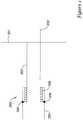
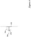
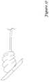
- FIG 1is a schematic illustration of an insertion sheath 200.
- the insertion sheath 200is inserted over a guidewire after an interventional procedure (such as an angioplasty or stent deployment procedure).
- the insertion sheath 200preferably includes a distal hemostatic seal (not shown) and a position indicator near the distal tip of the insertion sheath, which may provide an inlet for a bleed path which may flow through the insertion sheath to indicate the position of the insertion sheath relative to the vessel wall opening or other suitable indicator.
- a distal hemostatic sealnot shown
- a position indicatornear the distal tip of the insertion sheath
- the insertion sheathpreferably includes an insertion sheath tube 202 and an insertion sheath hub 204.
- the insertion sheath 200has a spring 206 or other force mechanism which can move the insertion sheath tube 202 distally relative to the insertion sheath hub 204 when the latch 208 is released in a subsequent step.
- the distal end of the insertion sheath tube 202is preferably beveled as shown at 203 and a corresponding indicator is placed on the proximal portion of the tube or on the hub so that the orientation of the bevel can be known by observation of the proximal portion of the insertion sheath.
- the bevelis omitted in other figures for ease of illustration.
- the interventional procedure sheathis exchanged with the insertion sheath 200 and dilator over a guidewire.
- the insertion sheath 200is positioned and oriented to the proper bevel angle using the orientation indicator and the distal end of the insertion sheath is positioned a predetermined distance inside the artery and past the artery wall 201 by using the bleed path or other indicator to indicate position.
- the insertion sheathis then held to retain proper position and the dilator and guidewire are removed.
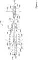
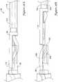
- the second stepis shown schematically with reference to Figures 2 and 3 .
- a device sheath 210is inserted into the insertion sheath 200 until the distal portion of the insertion sheath 200 is fed through the haemostatic valve and the device sheath 210 engages the hub 204 of the insertion sheath 200 and preferably clicks into place.
- the device sheathhas the anchor 212, plug 214, cinch disk 216 and suture 218 preloaded. The suture is attached to the device sheath at the proximal end 220 of the device sheath.
- the device sheath 210has a device sheath tube portion 222 and a handle portion 224.
- the handleincludes an outer portion 226 that is disposed over a first frame 228.
- the outer portion 226is shown in its further distal position relative to the first frame 228 and may be slid proximally relative to the first frame 228. This proximal motion is opposed by a spring 230 disposed between the outer portion 226 and the first frame 228.
- the device sheath 210also includes a second frame 232 disposed within the first frame 228.
- This second frame 232is initially fixed relative to the device sheath tube 222 and the components internal to the second frame 232 (discussed below) and may be moved relative to the first frame 228 and outer portion226.
- a spring 234is held between the proximal end of the second frame 232 and a pushing plate 236.
- the pushing plate 236is still fixed to the second frame 232.
- the pushing plateis attached to a pushing tube 238.
- the pushing tube 238has a compression plate 240 at its distalmost end, which abuts the cinch disk 216.
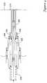
- the anchor 212is seated against the beveled edged 203 of the insertion sheath tube 202 by pushing the device sheath 210 against the insertion sheath 200.
- the device sheath tube 222has a shoulder 242 that hits against the insertion sheath tube 202 to check the proximal movement of the device sheath tube 222. As the device sheath 210 is still being moved distally relative to the insertion sheath 200, this movement breaks a connection 244 between the device sheath tube 222 and the second frame 232.
- the anchor 212is fixed to the second frame 232 by the suture 218 at the proximal end 220, and the anchor 212 therefore pushes the device sheath tube 222 proximally until the distal ends of the insertion sheath tube 202 and the device sheath tube 222 are proximate each other, as shown in Figure 3 .
- the componentsare sized such that at this point, the anchor 212 is properly seated against the beveled distal tip 203 of the insertion tube 200.
- the device sheath tube 22 and the insertion sheath tube 202are positioned so that the distal ends are proximate each other, the device sheath tube and insertion sheath tube are also fixed with respect to one another at latch 246.
- the second frame 232continues to move proximally until it latches to the first frame 228 at latch point 248, at which point the first frame and second frame are fixed relative to each other.
- the device sheath 210is move distally until the first frame 228 latches against the insertion sheath hub 204 at latch point 250, which fixes the first frame and insertion sheath hub relative to each other.
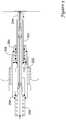
- the whole device(200 and 210) may be pulled proximally by pulling on the outer portion 226.
- This firstseats the anchor plug 212 against the artery wall 201, as shown in Figure 4 .
- the function of the spring 230 disposed between the first frame 228 and outer portion 226may be seen at this point. This spring 230 functions to control the amount of force transmitted from the outer portion 226 to the first frame 228.
- the first frame 228is fixedly connected to the insertion sheath hub 204 and to the second frame 232.
- the internal components not yet discussedare fixedly attached to the second frame 232.
- the insertion sheath tube 202is fixedly attached to the device sheath tube 222.
- the insertion sheath tube 202is also still attached to the insertion sheath hub 204.
- the anchor plug 212 positioned against the artery wall 201prevents the device from being pulled from the patient's body.
- a forcebuilds up in the mechanism.
- the connection 208 between the insertion sheath hub 204 and the insertion sheath tube 202is broken. This releases the spring 206 disposed between the insertion sheath tube 202 and hub 204.
- This spring 206expands to drive the insertion sheath tube 202 (and connected device sheath tube 222) proximally relative to the insertion sheath hub 204. This operates to retract the distal ends of the insertion sheath tube 202 and device sheath tube 222 from around the distal portion of the plug 214, as shown in Figure 5 .
- the operatorcontinues to pull the device (200 and 210) proximally by pulling on the outer portion 226, which further compresses the spring 230 between the outer portion 226 and the first frame 228 to provide a greater force.
- Thiscauses a second connection point 254 to release, between the second frame 232 and the pushing plate 236.
- Thisallows spring 234 to expand to advance to the pushing plate 236 distally.
- the pushing plate 236is connected through the pushing tube 238 to compression plate 240 and as the suture is still connected at 220 to the second frame 232, this motion advances the cinch disk 216 to compress and deploy the plug 214. This is illustrated in Figure 6 .
- a suture cutting mechanism 256may be friction fit to the pushing plate 236.
- Suture cutting mechanismswill be discussed more fully below, but for the purposes of this embodiment, it is sufficient to say that the suture cutting mechanism includes a long pull wire 258 with a blade at 260 at the distal end. The blade at the distal end is disposed in or proximate to a shearing block 262, which is fixed within the pushing tube 238. The suture or filament is threaded through the shearing block 262 and/or blade 260 such that relative movement of the shearing block 262 and blade 260 may cut the suture.
- the spring 234 at the proximal end of the second frame 232pushes the pushing plate 236 distally to advance the cinch disk 216 to compress and deploy the plug 214 as described above.
- This spring 234continues to expand and forces the suture cutting mechanism 256 against a stop 264.
- This stop 264is shown as part of the second frame 232.
- the spring 234forces the push plate 236 proximally relative to the suture mechanism 256.
- the device (200 and 210)is still pulled proximately by the outer portion 226. As the device is no longer attached to the anchor 212, this serves to retract the device from the body, leaving the anchor 212, plug 214, cinch disk 216 and suture 218 distal portion cinched to the artery wall to provide hemostasis, as illustrated in Figure 8 .
- Prior art devices and procedureshave more steps which must be performed by the user because certain automatic features incorporated into the present invention have previously been done manually by the user.
- the prior artis therefore more complicated to use.
- the present inventionaccomplishes certain actions in an automatically controlled manner, making the performance of the device more reliable, less affected by the orientations, forces, and movement speeds applied by the user.
- prior art devicestypically do not have automatic seating of the anchor against the insertion sheath bevel.
- prior art devicestypically do not have automatic tension and compressive forces applied to the plug.
- prior art devicestypically do not cut the suture automatically upon proper plug deployment.
- a second embodimentis illustrated with respect to Figures 9-17 .
- One difference between this embodiment and the previous embodimentis that the step of seating the anchor plug against the distal end of the insertion sheath tube is less automatic.
- Figure 9is a view illustrating the proximal portion of a second embodiment.
- the proximal portion of the device sheath 10 and the proximal portion of the insertion sheath 12are shown.
- the device sheathis slid into the insertion sheath tube 16 but is not yet engaged with the device sheath.
- the device sheathmay optionally include a button 14 or other trigger mechanism, which is pushed to allow the automated process to start. Such a button 14 may be useful to prevent premature deployment of the process.
- the insertion sheath 12preferably includes a distal hemostatic seal (not shown) and a position indication near the distal tip of the insertion sheath, which may provide an inlet for a bleed path which may flow through the insertion sheath to indicate the position of the insertion sheath relative to the vessel wall opening or other suitable indicator.
- a distal hemostatic sealnot shown
- a position indication near the distal tip of the insertion sheathwhich may provide an inlet for a bleed path which may flow through the insertion sheath to indicate the position of the insertion sheath relative to the vessel wall opening or other suitable indicator.
- the insertion sheathis inserted over a guidewire after an interventional procedure (such as an angioplasty or stent deployment procedure). This step is not illustrated in these figures.
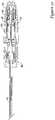
- Figure 10is a cross-sectional view of a device sheath similar to that of Figure 9 prior to the insertion of the device sheath into the insertion sheath.
- the anchor 18, plug 20, suture 22 and cinch disk 24are preloaded in the device sheath and the proximal end of the suture is fixed to the second frame 36. (An optional plug component 26 is shown in this figure).
- the anchoris kept in an insertion orientation by an orientation tube 28.
- the device sheath tube 30is fixed to the outer portion 32 by a fixation disk 34 or other suitable mechanism.
- the insertion sheathis already properly positioned through the artery wall.
- the insertion sheathpushes the orientation tube 28 distally.
- the insertion sheath tube 16keeps the anchor 18 in an insertion orientation until it deploys through the distal tip of the insertion sheath as illustrated in Figure 11 .
- the orientation tube 28is then housed within the device sheath hub 38 throughout the remainder of the procedure.
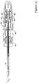
- the device sheathis inserted until an insertion sheath collar 40 is locked to the device sheath by a detent (not shown) or other mechanism. This is the state in Figure 11 .
- the insertion sheathis then held in place by an operator holding onto hub 42 and the device sheath 10 is retracted proximally by the operator. This moves the collar 40 relative to the hub 42 until the collar is locked in a second position by a detent 44 or other mechanism, as shown in Figure 12 . Because the insertion sheath tube 16 is fixed to the hub 42, and the anchor, plug, cinch disk, suture and device sheath tube 30 are fixed relative to the device sheath, this moves those components relative to the insertion sheath tube 16 to seat the anchor 18 against the distal end of the insertion sheath tube as shown in Figure 12 .
- the operatorreleases the insertion sheath, and continues to withdraw the device sheath proximally. This first seats the anchor 18 against the inner wall of the artery and next starts to move the internal components of the device sheath distally relative to outer portion 32.
- Figure 15is an exploded view.
- Second frame 36, spring 46, first tube 48, second tube 50 and pusher plate 52are illustrated. These components may also be seen in cross-section in Figure 12 , for example.
- these internal componentsare positioned as follows.
- Tabs 54 of second frame 36are in holes 56 of first tube 48. These two components are fixed relative to each other throughout the procedure.
- Tabs 56 of first tube 48are positioned through holes 60 of second tube 50 and the proximal ends of tabs 56 are disposed in slot 58 of pusher plate 52. This is a circumferential slot.
- the springis captured between second frame 36 and pusher plate 52.
- the distal end of first tube 48is somewhat proximal the distal end of second tube 50.
- first and second tubes 48 and 50The effect of this relative movement between first and second tubes 48 and 50 is to force tabs 48 to ride up on ramps 62. This forces the proximal end of the tabs 48 radially apart, which moves them out of slot 58. This releases spring 46.
- First tube 48also includes tables 68. These tabs 68 engage detents 64 and 66 as the internal components move proximally within outer portion 32. These tabs thereby prevent the internal components from being moved distally one the detents have been reached. Detents 66 are engaged by tabs 68 when the proximal edge of the second tube 50 reaches the stop at 60. Detents 64 are engaged by tabs 68 when the proximal edge of the second tube reaches the stop at 60.
- a suture cutting mechanism block 76is connected by a tube 78 (located between the suture and the pusher tube) to a cutting block 80.
- the sutureis threaded through the cutting block 80 and the shearing block 74.
- Block 76is friction fit to pusher plate 52.
- the proximal end of block 76reaches stop 82, the block 76 is driven into a cavity 84 of the pusher plate 52. Because the pusher plate is connected by pusher tube 70, 72 to pushing end/shearing block 74, and block 76 is connected by tube 78 to cutting block 80, a relative movement is created between the shearing block 74 and the cutting block 80, which cuts the suture.
- the devicemay be withdrawn, and the anchor, suture, plug and cinch disk are installed to create hemostasis.
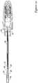
- FIGS. 18a and 18billustrate the distal portion of an automatic suture cutter device 90.
- the device 90includes a shearing block 92 and a cutting element 94.
- the shearing blockincludes a face 96 that abuts a corresponding face 98 of the cutting element.
- the faces 96 and 98may be flat or may have another complementary shape.
- a lumen 100is disposed in the shearing block 92.
- the lumen 100has a first opening 102 on the face 62 and a second proximal opening 104. Lumen 102 angles away from opening 102 to create a sharp edge on the proximal side of the opening 102.
- the cutting element 94includes a corresponding lumen 106 with an opening 108 on face 98 and another opening (not shown) on the other side of the cutting block. Lumen 106 angles away from opening 108 to create a sharp edge on the distal side of opening 108.
- the cutting element 94 and the shearing blockare initially aligned such that openings 102 and 108 are aligned.
- a suture 110is threaded through the openings.
- the cutting elementmay then be retracted to cut the suture.
- the angled edges of the openings 106 and 108act as a scissors to shear the suture.
- the cutting elementmay include a proximal hole 112 to receive the suture and may be attached to a tube or wire 114, which can be acted on to actuate the cutting mechanism.
- the shearing block 92may include a central opening in the distal face through which the suture may be threaded. Both the shearing block and the cutting element are confined within a tube; this allows movement of the cutting element relative to the shearing block only along the direction of the arrow.
- shearing block 96may correspond to shearing block 74 of the previous embodiment and cutting element 94 may correspond to cutting block 80.
- the suture cuttingmay be triggered automatically as described above.
- FIG. 19aAnother embodiment 120 of an automatic cutting mechanism is shown with respect to Figures 19a and 19b .
- This embodimentincludes a tube 122 that has a suture lumen 124 and a cutting wire lumen 126.
- a shearing block 128is fixed to the tube and includes a first lumen 130 for the suture and a second lumen 132 for the cutting wire 134.
- the first and second lumenscross in the shearing block.
- the cutting wire 134has a distal end disposed in the cutting block and preferably has a loop (seen in cross section) with a cutting edge 136 on the inside of the loop.
- the loopis sized such that in a first position (shown in Figure 19a ), the cutting wire can be positioned so that it does not impinge on lumen 130.
- the cutting wire 134may be retracted proximally to sever the suture.
- the shearing blockhas an angled hole through which the suture passes.
- the suturecan move freely through the hole in either direction as needed by the delivery motions of the device.
- the cutting edge of the cutting elementis initially positioned so that the suture is not contacted by the cutting edge until desired.
- the following figureillustrates the suture passing through the shearing block and other components. In this position, the suture is free to move relative to the cutter apparatus.
- the shearing block location within the device sheath, and the length of the cutting elementis chosen to cut the suture at a location long enough to minimize any risk of unintended suture release from the cinch disk, but short enough to be sufficiently far underneath the skin to minimize any risk of infection. Reduced length of suture also reduces the inflammatory response which occurs during biodegradation of a degradable suture.
- the shearing blockcan be fixed at a particular location in the device sheath to allow enough space for the implantable portions, but little excess space.
- the shearing blockcan be advanced, such as together with the cinching movement, to follow the cinch disk and minimize the excess length of suture.
- the shearing block and cutting elementcan be advanced or retracted together at various stages in the deployment of the vascular closure device to provide for proper coordinated function of the deployment system.
- the following figureillustrates the cutter apparatus advanced along the suture; such advancement may be used during plug compression during vascular closure device deployment.
- the handlecan have interacting features so that after the cinching movement occurs, the cutting element is automatically moved to cause the cutting of the suture.
- a manual actuator for the cutting elementcan be provided.
- the cutting movement of the cutting elementcan be either inward or outward, depending on the geometry of the cutting edge and shearing block.
- the present exampleshows the cutting element pulled back to cause the cutting of the suture.
- the cutter mechanismis removed from the body; this motion may be combined with removal of the device sheath, handle, or other elements of the system. The removal may also be combined with retraction of the cutting element which produces the cutting, in an orderly or automatic manner.
- the following figureillustrates the cutting apparatus being removed after the suture has been cut.
- Other elements of the vascular closure deviceare not shown in these illustrations, but include an anchor, plug, and cinch disk, for example.
- the suture cuttermust be sufficiently flexible to allow for access and use; as examples, the cutter assembly extension can be made of a polymer, or slotted metal tube, which have sufficient strength but are flexible in bending.
- the handle end of the cutting apparatushas steps, attachments, latch components, linkages or other features so that the motion of the cutter assembly extension, the cutting element, and the suture extension are actuated from the delivery system handle.
- the cuttercan be advanced during plug compression, and the cutting element retracted to cut the suture, in a coordinated and automated manner during the device deployment sequence, using manual forces and displacements, latch release spring deployments, motor driven displacements, or other means.
- the suturecan be a continuous length of suture from the anchor, through the plug and cinch disk, all the way to the handle.
- a predetermined amount of suture extensioncan be accommodated, such as that obtained by a force-actuated triggering of the suture cutting.
- a shorter length of suturecan be coupled to a suture extension such as a more rigid filament, wire or tube structure such as by swaging, fastening using a tubing fastener, or other bonding means.
- the suture extensioncan reduce the total displacement due to stretching of the suture during deployment of the vascular closure device, enhancing the positional control and improving the reliability of the device deployment.
- the shearing blockcan be a static structure with a hole through which the suture passes, or it can have a shape or orientation change, such as from straight to angled, to reduce friction between the suture and the shearing block during cinching, yet obtain an angled hole orientation for effective cutting.
- Multiple componentscan be used to achieve a shape change, or the shearing block can rotate to reorient the hole, or the shearing block can deform to better capture and control the suture and facilitate cutting by the cutting element.
- a feature incorporated with the cutting elementcan push or actuate an orientation change for the shearing block hole, so that the reorientation happens automatically when the cutting element is pulled back.
- the cutting surface portion of the cutting elementcan slide with respect to the shearing block; in one relative orientation the shearing block holds the suture away from the cutting element to prevent damage to the suture. In another relative orientation the cutting element passes across the hole in the shearing block to cut the suture. For example, by pulling on the proximal end of the cutting element, which is accomplished either automatically or by actuation of the delivery device handle, the cutting element is retracted a short distance to trim the suture at the location of the shearing block. The cutting element, shearing block, and excess suture are removed with the device sheath at the conclusion of the procedure.
- the shearing blockcan have a sharp edge rather than the cutting element, or both can have a sharp edge.
- the cutting elementis typically withdrawn to trim the suture to length. However, most motions of the cutting element can be reversed in orientation, so that the cutting element can be advanced a short distance to trim the suture to length.
- the cutting or shearing edge(s)can be oriented for close contact on advancing or on retracting of one or more elements.
- the suturecan take a straight path through cutter components, or the suture can be displaced to take a curved or angled path through cutter components to facilitate the cutting.
- the shearing blockcan be advanced or withdrawn a short distance against a stationary cutting element to trim the suture to length.
- a manual actuation featuresuch as a grasping ring can be incorporated to provide additional movement or control in case the automatic actuation fails to completely trim the suture.
- the suture cutting apparatuscan be modified to provide for minimally-invasive or automated cutting of sutures, even if the sutures are not associated with an anchor plug cinch type of vascular closure device.
- a pulley system, or gear system, or hydraulic system, or other mechanical systemcan be incorporated into the handle.
- the apparatuscan be shaped like a syringe, or have an angled handle like a gun, or have concentric sliding cylinders with flanges, or have a squeeze mechanism where two portions of the handle are squeezed together to actuate the cinching mechanism, or have other configuration as is convenient for the principle actuations of components: attachment of handle to insertion sheath, and proximal movement to snug anchor against the insertion sheath and the artery and retract sheath and deploy and cinch the plug. Other actuations can still happen automatically, such as suture tensioning, controlled travel for cinching and deployment, and releasing of the suture, in keeping with the present invention.
- Mechanical advantagecan be incorporated if desired.
- An alternate embodimentutilizes sliding finger hooks, where the finger hooks slide in channels in the handle, where the sliding action automatically actuates a short distance retraction to provide the gap for plug deployment.
- an automatic precompression actioncan be provided to pre-compress the plug prior to retraction of the sheaths.
- Alternative cinch mechanisms other than the cinch diskinclude a cinch knot, a friction disk, a crimp, a friction tube, thermal forming, and elastic "spring” actuation, and combinations.
- the plugcan enhance hemostasis by swelling and physically filling space.
- the plugcan expand from a crumpled, folded or other compressed state to a less-crumpled, folded, or otherwise compressed state to fill space for improved hemostasis.
- Thrombosis-promoting surfaces, morphology, chemistry, or medicationcan be incorporated to promote clotting for improved hemostasis.
- Combinations of hemostasis enhancement meanscan be utilized.
- Indicatorscan be added to the device to inform the user of certain successful operations, or steps not performed, such as alignment markings, windows, flags, tabs, sounds, colors, snaps and stops felt by the hand, and so forth. These indicators could indicate locking of the hub, seating of the anchor, advancement of the push rod, and so forth.
Landscapes
- Health & Medical Sciences (AREA)
- Surgery (AREA)
- Life Sciences & Earth Sciences (AREA)
- Biomedical Technology (AREA)
- Nuclear Medicine, Radiotherapy & Molecular Imaging (AREA)
- Engineering & Computer Science (AREA)
- Cardiology (AREA)
- Heart & Thoracic Surgery (AREA)
- Medical Informatics (AREA)
- Molecular Biology (AREA)
- Animal Behavior & Ethology (AREA)
- General Health & Medical Sciences (AREA)
- Public Health (AREA)
- Veterinary Medicine (AREA)
- Surgical Instruments (AREA)
Description
- The present invention relates generally to medical devices for sealing and closing passages formed through tissue. More specifically, the present invention relates to apparatuses or devices for sealing or closing an opening formed through biological tissue to control, prevent or stop bleeding or other biological fluid or tissue.
- In many medical procedures, such as, for example, balloon angioplasty and the like, an opening can be created in a blood vessel or arteriotomy to allow for the insertion of various medical devices which can be navigated through the blood vessel to the site to be treated. For example, after initial access with a hollow needle, a guidewire may first be inserted through the tissue tract created between the skin, or the epidermis, of the patient down through the subcutaneous tissue and into the opening formed in the blood vessel. The guidewire is then navigated through the blood vessel to the site of the occlusion or other treatment site. Once the guidewire is in place, an introducer sheath can be slid over the guide wire to form a wider, more easily accessible, tract between the epidermis and the opening into the blood vessel. The appropriate medical device can then be introduced over the guidewire through the introducer sheath and then up the blood vessel to the site of the occlusion or other treatment site.
- Once the procedure is completed, the medical devices or other equipment introduced into the vessel can be retracted through the blood vessel, out the opening in the blood vessel wall, and out through the tissue tract to be removed from the body. The physician or other medical technician is presented with the challenge of trying to close the opening in the blood vessel and/or the tissue tract formed in the epidermis and subcutaneous tissue. A number of different device structures, assemblies, and methods are known for closing the opening in the blood vessel and/or tissue tract, each having certain advantages and disadvantages. However, there is an ongoing need to provide new and improved device structures, assemblies, and/or methods for closing and/or sealing the opening in the blood vessel and/or tissue tract.
- Arteriotomy closure after diagnostic and/or interventional catheterization procedures has been addressed by a number of devices in addition to standard manual compression. One of the most successful approaches has been the use of a collagen plug placed external to the artery, held in place by a biodegradable polymer (such as PLGA) anchor inside the artery, with these two components held together by a suture which passes through the arteriotomy. The components are essentially cinched together to stabilize the components in place with arterial wall tissue pinched between the plug and anchor to maintain approximation for a period of time before sufficient clotting, tissue cohesion, and/or healing occurs to prevent significant bleeding complications. While this approach has had success, there are drawbacks with these devices. The primary problems are that bleeding complications still occur, arterial occlusion problems occur, and there are many steps required to properly implant these devices which require effort by the practitioner, training, and careful attention to various manually-performed steps to reduce the occurrence of complications. One step common to most of the prior approaches has been trimming of the cinching suture at the conclusion of the procedure. This is typically performed by pulling tension on the suture manually, depressing the skin manually, and trimming the suture manually. The suture is trimmed close to the depressed skin so that when the skin is released, the ends of the suture are underneath the surface of the skin. This is important to reduce infections which would be more likely if the suture extends to the skin because this would maintain an access path from outside the body through the normally protective skin layer to the tissues underneath. This is typically not a difficult procedure, but nevertheless represents steps which are presently performed manually, taking more time than necessary, and must be done carefully to trim the suture to the correct length. It may be desired to trim the suture a bit farther underneath the skin than is easily accomplished by this method; this may be desired to minimize infection risks, for example. The present invention overcomes these problems by providing an apparatus which automates the suture cutting, and can easily cut the suture at a location deeper under the skin if desired, providing a faster procedure and an improved safety margin for trimming location.
WO 99/22646 A1 WO 2009/025836 A1 discloses various embodiments of a device for closing a vascular access puncture site following percutaneous diagnostic or therapeutic interventional procedures. In one embodiment, the closure device includes a vessel locating member, an anchor and a sealing material. The closure device may be configured to deploy the anchor and the sealing material outside of a hole in a blood vessel to close the hole. The vessel locating member may be used to locate the blood vessel to ensure that the anchor and/or the sealing material are properly placed adjacent to the hole. The closure device may also include a tamper member configured to push or tamp the sealing material against the anchor. The closure device may also include a suture that is used to hold the sealing material and the anchor together adjacent to the hole in the blood vessel. - Prior art devices require complex techniques that require many steps to properly implant these devices. This requires training and careful attention to various manually-performed steps to reduce the occurrence of complications. The present invention overcomes these problems by providing an apparatus which automates the implantation procedure, thereby providing more reliable sealing, and reducing the complexity of using the device.
Figure 1 is a schematic view of anintroducer sheath 200 passing through avessel wall 201;Figure 2 is a schematic view of adevice sheath 210 with a vascular closure device loaded therein inserted into the introducer sheath ofFigure 1 ;Figure 3 is a schematic view of theintroducer sheath 200 anddevice sheath 210 combination during a step of a process of deploying the vascular closure device;Figure 4 is a schematic view of theintroducer sheath 200 anddevice sheath 210 combination during a step of a process of deploying the vascular closure device;Figure 5 is a schematic view of theintroducer sheath 200 anddevice sheath 210 combination during a step of a process of deploying the vascular closure device;Figure 6 is a schematic view of theintroducer sheath 200 anddevice sheath 210 combination during a step of a process of deploying the vascular closure device;Figure 7 is a schematic view of theintroducer sheath 200 anddevice sheath 210 combination during a step of a process of deploying the vascular closure device;Figure 8 is a schematic view of a deployed vascular closure device;Figure 9 is an isometric view of the proximal portion, including the handle, of a device sheath;Figure 10 is a cross-sectional view of a device sheath with a vascular closure device loaded therein;Figure 11 is a cross-sectional view of the device sheath ofFigure 10 inserted into an introducer sheath;Figure 12 is a cross-sectional view of the device sheath and introducer sheath ofFigure 11 during a step of a process of deploying the vascular closure device;Figure 13 is a cross-sectional view of the device sheath and introducer sheath ofFigure 11 during a step of a process of deploying the vascular closure device;Figure 14 is a cross-sectional view of the device sheath and introducer sheath ofFigure 11 during a step of a process of deploying the vascular closure device;Figure 15 is an exploded view of certain interior components of an introducer sheath;Figure 16 is an exploded view of the proximal portion of an introducer sheath;Figure 17 is a view of a deployed vascular occluder device;Figure 18A is a side view of a suture cutting mechanism with a suture therein;Figure 18B is a side view of a suture cutting mechanism with a cut suture therein;Figure 19A is a side schematic view of a suture cutting mechanism with a suture therein; andFigure 19B is a side schematic view of a suture cutting mechanism with a partially cut suture therein.- The following summary is provided to facilitate an understanding of some of the innovative features unique to the present disclosure and is not intended to be a full description. A full appreciation of the disclosure can be gained by taking the entire specification, claims, drawings, and abstract as a whole. The invention is defined by the claims.
- The present disclosure relates generally to medical devices and more particularly to methods and devices for closing and/or sealing punctures in tissue. In one illustrative embodiment, a device is provided for delivering and deploying an anchor, plug, filament and locking mechanism adjacent to the opening in the vessel wall and/or tissue tract. In some cases, the anchor may be automatically seated against the vessel wall. In some cases, the plug is compressed and the filament is trimmed automatically. In some cases, the anchor is seated, the plug is compressed and the filament is trimmed automatically.
- The disclosure pertains to apparatuses and methods for implantation and deployment of an anchor-plug-cinch vascular closure device. The implantation and deployment apparatus may comprise an automated plug deployment mechanism having actuation means, drive mechanism, automatic sheath retraction mechanism, automatic anchor seating mechanism, automatic cinching mechanism, optional cinching speed control means, and automated suture trimming or release. The mechanism provides automatic cinching of an extravascular plug towards an intravascular anchor with controlled plug compression. The cinching motion can be controlled to a variable rate by various means such as orifice flows or springs or electro-magnetic-mechanical speed governing to provide for reduced actuation forces to minimize damage to the plug material and the anchor. For example, a gradual acceleration or deceleration period, with different velocity or driving force than other portions of the cinching travel, can be used to avoid tearing the plug, or bending or breaking the anchor. Various steps in the deployment process are accomplished automatically in the desired sequence while minimizing required user action.
- The anchor-plug-cinch vascular closure device comprises an anchor, a plug, and a cinch and is similar to those described in of application Serial No.
12/390,241, filed Feb. 20, 2009 - The implantation and deployment apparatus provides automated deployment of the anchor-plug-cinch vascular closure device. The implantation and deployment apparatus comprises elongated components for introduction of the anchor, plug, and cinch into the body, including an insertion sheath and dilator, with an orientation indicator, a hub with a hemostatic valve and an elongated thinwalled tube formed with a distal bevel to accommodate the anchor at the desired deployment angle for proper approximation to the artery. A locating mechanism is incorporated, such as a bleed path in the insertion sheath and dilator for locating the sheath at the desired location in the artery.
- The implantation and deployment apparatus further comprises a device sheath which passes through the insertion sheath and is affixed to a handle. The anchor of the anchor-plug-cinch vascular closure device is disposed in or adjacent to the distal end of the device sheath for introduction into the body. The anchor is affixed to the distal end of an elongated portion of the cinch mechanism (herein referred to as the "suture"). The suture extends through the device sheath. The plug is disposed proximal to the anchor and within the device sheath and is captured or retained by the suture. A cinching or locking element (herein referred to as the "cinch disk") is disposed adjacent and proximal to the plug and within the device sheath. The implantation device also includes a push rod (typically tubular) which passes through the proximal portion of the device sheath to the plug. During the deployment procedure, the push rod, suture, plug, device sheath, and anchor pass through the insertion sheath so that the anchor just passes out the end of the insertion sheath but other components largely do not.
- The handle is affixed to the device sheath and comprises a body portion, a hub connector portion, an actuation portion (optionally automatic), an automatic anchor seating mechanism, a sheath retraction mechanism (optionally automatic), an automatic cinching mechanism, and optionally comprises a suture trimming mechanism (optionally automatic); other grasping, orienting, indicating, and control elements can be incoroporated.
- The hub connector portion attaches to the insertion sheath hub, in a single orientation so that the relative orientation of the handle (and device sheath) and the insertion sheath (and bevel) are maintained when attached.
- The actuation portion provides for arming the device and/or triggering the actions of the device. The actuation portion can include a lock or latch which is actuated by user manipulation. The actuation portion can include a latch or button which triggers the various retractions and cinching and other actions of the device in sequence. The actuation can be by application of force such as by pulling back on a portion of the delivery system after the anchor is in place in the vessel. The actions can all occur in sequence from a single trigger, or multiple triggering manipulations can be used to cause multiple sequences of device actions or single actions. Whether by manual or automatic retraction, the device is retracted until the anchor is seated snugly against the vessel wall.
- The suture is attached to the automatic anchor seating mechanism. The automatic anchor seating mechanism can be activated by attachment of the hub connector portion of the handle body to the insertion sheath hub; the mechanism then retracts the suture and anchor (and may also retract other components such as the device sheath, plug, and cinch disk) relative to the introduction sheath a predetermined distance proximally to snug the anchor up against the beveled end of the insertion sheath. The automatic anchor seating mechanism can incorporate a speed limiting feature if desired to slow the movement and give the anchor sufficient time to move into alignment with the insertion sheath bevel, such as by incorporating a dashpot or other inertial or frictional mechanism; a moderate strength spring, for example, can retract the suture at an appropriate speed. The anchor seating mechanism has sufficient travel to accommodate any elongation of the suture.
- The sheath retraction mechanism provides an appropriate sheath to anchor gap to allow proper deployment of the plug. Displacement can be provided to produce the desired sheath to anchor gap by paying out a predetermined length of suture, by sliding of a suture mounting element, by retraction of the device sheath hub relative to the introduction sheath hub, or by other means. Actuation of the sheath retraction mechanism can be automatically triggered, for example, by application of an appropriate retraction force by the user to pull the anchor against the vessel wall. One or more latches can be provided so that upon completion of the movement of the automatic anchor seating mechanism, automatic sheath retraction mechanism, or other mechanisms, the mechanism latches so to prevent further unwanted movement even if force is applied.
- The automatic cinching mechanism advances the cinch disk, advances and axially compresses the plug (which deploys by radially expanding) and cinches the plug against the anchor. The cinching mechanism can be automatically triggered, for example, at the completion of the sheath retraction mechanism travel, or by application of an appropriate retraction force higher than the force which triggered the sheath retraction mechanism, or by manually pressing a button or releasing a latch, or by other means. The cinching mechanism also advances the cinch disk which maintains the implanted device in a cinched configuration after the procedure. When the cinching mechanism is completely actuated, the suture can be cut or otherwise released by an automatic suture cutting or release mechanism, which releases the suture from device so that the handle, device sheath, push rod, and insertion sheath can be withdrawn, leaving the anchor, plug, suture, and cinch disk in place. If an automatic suture cutting or release mechanism is not utilized, the skin is depressed an the suture trimmed to length manually so that it does not extend out past the skin.
- The hub connector portion of the handle and/or the insertion sheath hub preferably have orientation features such as asymmetric shapes or pins or slots, etc., which allow the hub connector portion of the handle to mate with the insertion sheath hub in only one orientation, and which facilitate the attachment of the two pieces. Other shapes than those indicated in the drawings for the hub can be utilized, such as, for example, varying aspect ratios, angles, insertion depth, male/female, D- or squared- or rounded- components, convex/concave.
- Some internal features and mechanisms which perform the described functions are not indicated in the figures to better illustrate the overall function of the disclosure. Such internal mechanisms can include, for example, springs, latches, levers, pulleys, strings, friction fits, dashpots, gas reservoirs.
- In the embodiment described below with references to
Figures 1-8 , certain conventions are used. Figures schematically illustrate the steps. (In the figures, the bevel is not shown, and the orientation is perpendicular to the artery for simplicity of illustration. Some latches are indicated diagrammatically as dots.) - The preferred method of achieving arteriotomy closure comprises the following steps. The steps are typically, but not necessarily, performed in the order listed. Certain steps can be combined or performed separately by configuration of the internal mechanisms. Preferably, steps are performed automatically as indicated. Alternatively, certain steps could include manual actuations, although this is less advantageous.
Figure 1 is a schematic illustration of aninsertion sheath 200. Theinsertion sheath 200 is inserted over a guidewire after an interventional procedure (such as an angioplasty or stent deployment procedure). Theinsertion sheath 200 preferably includes a distal hemostatic seal (not shown) and a position indicator near the distal tip of the insertion sheath, which may provide an inlet for a bleed path which may flow through the insertion sheath to indicate the position of the insertion sheath relative to the vessel wall opening or other suitable indicator. Such features are described in the '241 application above.- The insertion sheath preferably includes an
insertion sheath tube 202 and aninsertion sheath hub 204. In this embodiment, theinsertion sheath 200 has aspring 206 or other force mechanism which can move theinsertion sheath tube 202 distally relative to theinsertion sheath hub 204 when thelatch 208 is released in a subsequent step. - The distal end of the
insertion sheath tube 202 is preferably beveled as shown at 203 and a corresponding indicator is placed on the proximal portion of the tube or on the hub so that the orientation of the bevel can be known by observation of the proximal portion of the insertion sheath. The bevel is omitted in other figures for ease of illustration. - In this step, the interventional procedure sheath is exchanged with the
insertion sheath 200 and dilator over a guidewire. Theinsertion sheath 200 is positioned and oriented to the proper bevel angle using the orientation indicator and the distal end of the insertion sheath is positioned a predetermined distance inside the artery and past theartery wall 201 by using the bleed path or other indicator to indicate position. The insertion sheath is then held to retain proper position and the dilator and guidewire are removed. - The second step is shown schematically with reference to
Figures 2 and3 . In this step adevice sheath 210 is inserted into theinsertion sheath 200 until the distal portion of theinsertion sheath 200 is fed through the haemostatic valve and thedevice sheath 210 engages thehub 204 of theinsertion sheath 200 and preferably clicks into place. The device sheath has theanchor 212, plug 214,cinch disk 216 andsuture 218 preloaded. The suture is attached to the device sheath at theproximal end 220 of the device sheath. - The
device sheath 210 has a devicesheath tube portion 222 and ahandle portion 224. The handle includes anouter portion 226 that is disposed over afirst frame 228. Theouter portion 226 is shown in its further distal position relative to thefirst frame 228 and may be slid proximally relative to thefirst frame 228. This proximal motion is opposed by aspring 230 disposed between theouter portion 226 and thefirst frame 228. - The
device sheath 210 also includes asecond frame 232 disposed within thefirst frame 228. Thissecond frame 232 is initially fixed relative to thedevice sheath tube 222 and the components internal to the second frame 232 (discussed below) and may be moved relative to thefirst frame 228 and outer portion226. Aspring 234 is held between the proximal end of thesecond frame 232 and a pushingplate 236. At this point, the pushingplate 236 is still fixed to thesecond frame 232. The pushing plate is attached to a pushingtube 238. The pushingtube 238 has acompression plate 240 at its distalmost end, which abuts thecinch disk 216. - The
anchor 212 is seated against the beveled edged 203 of theinsertion sheath tube 202 by pushing thedevice sheath 210 against theinsertion sheath 200. Thedevice sheath tube 222 has ashoulder 242 that hits against theinsertion sheath tube 202 to check the proximal movement of thedevice sheath tube 222. As thedevice sheath 210 is still being moved distally relative to theinsertion sheath 200, this movement breaks aconnection 244 between thedevice sheath tube 222 and thesecond frame 232. Theanchor 212 is fixed to thesecond frame 232 by thesuture 218 at theproximal end 220, and theanchor 212 therefore pushes thedevice sheath tube 222 proximally until the distal ends of theinsertion sheath tube 202 and thedevice sheath tube 222 are proximate each other, as shown inFigure 3 . The components are sized such that at this point, theanchor 212 is properly seated against the beveleddistal tip 203 of theinsertion tube 200. When thedevice sheath tube 22 and theinsertion sheath tube 202 are positioned so that the distal ends are proximate each other, the device sheath tube and insertion sheath tube are also fixed with respect to one another atlatch 246. - The
second frame 232 continues to move proximally until it latches to thefirst frame 228 atlatch point 248, at which point the first frame and second frame are fixed relative to each other. - The
device sheath 210 is move distally until thefirst frame 228 latches against theinsertion sheath hub 204 atlatch point 250, which fixes the first frame and insertion sheath hub relative to each other. - Once the
anchor 212 is seated against the distal end of theinsertion sheath tube 202, the whole device (200 and 210) may be pulled proximally by pulling on theouter portion 226. This first seats theanchor plug 212 against theartery wall 201, as shown inFigure 4 . The function of thespring 230 disposed between thefirst frame 228 andouter portion 226 may be seen at this point. Thisspring 230 functions to control the amount of force transmitted from theouter portion 226 to thefirst frame 228. - It is helpful to recall that at this point in the process, the
first frame 228 is fixedly connected to theinsertion sheath hub 204 and to thesecond frame 232. The internal components not yet discussed are fixedly attached to thesecond frame 232. Theinsertion sheath tube 202 is fixedly attached to thedevice sheath tube 222. Finally, theinsertion sheath tube 202 is also still attached to theinsertion sheath hub 204. - When the device (200 and 210 together) is pulled proximally by pulling on the
outer portion 226, theanchor plug 212 positioned against theartery wall 201 prevents the device from being pulled from the patient's body. A force builds up in the mechanism. When a predetermined level of force is reached, theconnection 208 between theinsertion sheath hub 204 and theinsertion sheath tube 202 is broken. This releases thespring 206 disposed between theinsertion sheath tube 202 andhub 204. Thisspring 206 expands to drive the insertion sheath tube 202 (and connected device sheath tube 222) proximally relative to theinsertion sheath hub 204. This operates to retract the distal ends of theinsertion sheath tube 202 anddevice sheath tube 222 from around the distal portion of theplug 214, as shown inFigure 5 . - The operator continues to pull the device (200 and 210) proximally by pulling on the
outer portion 226, which further compresses thespring 230 between theouter portion 226 and thefirst frame 228 to provide a greater force. This causes asecond connection point 254 to release, between thesecond frame 232 and the pushingplate 236. This allowsspring 234 to expand to advance to the pushingplate 236 distally. As the pushingplate 236 is connected through the pushingtube 238 tocompression plate 240 and as the suture is still connected at 220 to thesecond frame 232, this motion advances thecinch disk 216 to compress and deploy theplug 214. This is illustrated inFigure 6 . - There are several further components that may be attached to the pushing
plate 236 and pushingtube 238. Asuture cutting mechanism 256 may be friction fit to the pushingplate 236. Suture cutting mechanisms will be discussed more fully below, but for the purposes of this embodiment, it is sufficient to say that the suture cutting mechanism includes along pull wire 258 with a blade at 260 at the distal end. The blade at the distal end is disposed in or proximate to ashearing block 262, which is fixed within the pushingtube 238. The suture or filament is threaded through theshearing block 262 and/orblade 260 such that relative movement of theshearing block 262 andblade 260 may cut the suture. - Once the
connection point 254 is released, thespring 234 at the proximal end of thesecond frame 232 pushes the pushingplate 236 distally to advance thecinch disk 216 to compress and deploy theplug 214 as described above. Thisspring 234 continues to expand and forces thesuture cutting mechanism 256 against astop 264. Thisstop 264 is shown as part of thesecond frame 232. At this point, thespring 234 forces thepush plate 236 proximally relative to thesuture mechanism 256. Because thesuture mechanism 256 is fixed to theblade 260 by thepull wire 258 and because theshearing block 262 is fixed within thepush tube 238 which is still being pushed by thepush plate 236, relative movement between theblade 260 and theshearing block 262 is created, which cuts thesuture 218. This is illustrated schematically inFigure 7 . - The device (200 and 210) is still pulled proximately by the
outer portion 226. As the device is no longer attached to theanchor 212, this serves to retract the device from the body, leaving theanchor 212, plug 214,cinch disk 216 andsuture 218 distal portion cinched to the artery wall to provide hemostasis, as illustrated inFigure 8 . - Since many of the actions occur automatically, the procedure is streamlined from a user perspective. The user steps condense to the following:
- 1. Swap the interventional sheath for the
insertion sheath 200 and position theinsertion sheath 200 using bleed indicator. - 2. Hold the insertion sheath position, and insert the
device sheath 210 until it engages the insertion sheath hub 204 (theanchor 212 automatically seats against the insertion sheath bevel 203). - 3. Retract the device handle 224 to deploy the device and remove the delivery system (the sheath retraction, cinch mechanism, and suture cutting all happen automatically in sequence).
- Prior art devices and procedures have more steps which must be performed by the user because certain automatic features incorporated into the present invention have previously been done manually by the user. The prior art is therefore more complicated to use. Also, the present invention accomplishes certain actions in an automatically controlled manner, making the performance of the device more reliable, less affected by the orientations, forces, and movement speeds applied by the user. For example, prior art devices typically do not have automatic seating of the anchor against the insertion sheath bevel. Also, prior art devices typically do not have automatic tension and compressive forces applied to the plug. Also, prior art devices typically do not cut the suture automatically upon proper plug deployment. These and other features streamline the use of the device and provide improved reliability over the prior art.
- A second embodiment is illustrated with respect to
Figures 9-17 . One difference between this embodiment and the previous embodiment is that the step of seating the anchor plug against the distal end of the insertion sheath tube is less automatic. Figure 9 is a view illustrating the proximal portion of a second embodiment. InFigure 9 , the proximal portion of thedevice sheath 10 and the proximal portion of theinsertion sheath 12 are shown. The device sheath is slid into theinsertion sheath tube 16 but is not yet engaged with the device sheath.- The device sheath may optionally include a
button 14 or other trigger mechanism, which is pushed to allow the automated process to start. Such abutton 14 may be useful to prevent premature deployment of the process. - The
insertion sheath 12 preferably includes a distal hemostatic seal (not shown) and a position indication near the distal tip of the insertion sheath, which may provide an inlet for a bleed path which may flow through the insertion sheath to indicate the position of the insertion sheath relative to the vessel wall opening or other suitable indicator. Such features are described in the '241 application above. - In the first step, the insertion sheath is inserted over a guidewire after an interventional procedure (such as an angioplasty or stent deployment procedure). This step is not illustrated in these figures.
Figure 10 is a cross-sectional view of a device sheath similar to that ofFigure 9 prior to the insertion of the device sheath into the insertion sheath. Theanchor 18, plug 20,suture 22 andcinch disk 24 are preloaded in the device sheath and the proximal end of the suture is fixed to thesecond frame 36. (Anoptional plug component 26 is shown in this figure). The anchor is kept in an insertion orientation by anorientation tube 28. Thedevice sheath tube 30 is fixed to theouter portion 32 by afixation disk 34 or other suitable mechanism.- With reference to
Figures 11 and12 , the steps of inserting the anchor through the artery wall and seating the anchor against the distal end of the insertion sheath tube are described. - While the artery wall is not illustrated in these figures, it is contemplated that prior to
Figure 11 , the insertion sheath is already properly positioned through the artery wall. When thedevice sheath 10 is inserted into theinsertion sheath 12, the insertion sheath pushes theorientation tube 28 distally. Theinsertion sheath tube 16 keeps theanchor 18 in an insertion orientation until it deploys through the distal tip of the insertion sheath as illustrated inFigure 11 . Theorientation tube 28 is then housed within thedevice sheath hub 38 throughout the remainder of the procedure. - The device sheath is inserted until an
insertion sheath collar 40 is locked to the device sheath by a detent (not shown) or other mechanism. This is the state inFigure 11 . - The insertion sheath is then held in place by an operator holding onto
hub 42 and thedevice sheath 10 is retracted proximally by the operator. This moves thecollar 40 relative to thehub 42 until the collar is locked in a second position by adetent 44 or other mechanism, as shown inFigure 12 . Because theinsertion sheath tube 16 is fixed to thehub 42, and the anchor, plug, cinch disk, suture anddevice sheath tube 30 are fixed relative to the device sheath, this moves those components relative to theinsertion sheath tube 16 to seat theanchor 18 against the distal end of the insertion sheath tube as shown inFigure 12 . - The operator releases the insertion sheath, and continues to withdraw the device sheath proximally. This first seats the
anchor 18 against the inner wall of the artery and next starts to move the internal components of the device sheath distally relative toouter portion 32. - Some of those internal components can be better seen with reference to
Figure 15 , which is an exploded view.Second frame 36,spring 46,first tube 48,second tube 50 andpusher plate 52 are illustrated. These components may also be seen in cross-section inFigure 12 , for example. - In the step of
Figure 12 , these internal components are positioned as follows.Tabs 54 ofsecond frame 36 are inholes 56 offirst tube 48. These two components are fixed relative to each other throughout the procedure.Tabs 56 offirst tube 48 are positioned throughholes 60 ofsecond tube 50 and the proximal ends oftabs 56 are disposed inslot 58 ofpusher plate 52. This is a circumferential slot. The spring is captured betweensecond frame 36 andpusher plate 52. The distal end offirst tube 48 is somewhat proximal the distal end ofsecond tube 50. - When the operator continues to withdraw the device (moving from
Figure 12 to Figure 13 ), these internal components move distally relative toouter portion 32. The distal end ofsecond tube 50 hits a stop at 60. The first tube is forced to continue moving distally by its connection to the second frame until its distal end also hits the stop at 60. - The effect of this relative movement between first and
second tubes tabs 48 to ride up onramps 62. This forces the proximal end of thetabs 48 radially apart, which moves them out ofslot 58. This releasesspring 46. First tube 48 also includes tables 68. Thesetabs 68 engagedetents outer portion 32. These tabs thereby prevent the internal components from being moved distally one the detents have been reached.Detents 66 are engaged bytabs 68 when the proximal edge of thesecond tube 50 reaches the stop at 60.Detents 64 are engaged bytabs 68 when the proximal edge of the second tube reaches the stop at 60.- In
Figure 14 , one can see the effect of releasingspring 46.Spring 46drives pusher plate 52 distally, which pushespusher tube cinch disk 24. This compresses theplug 20. - Also included in this embodiment are components related to the suture cutting mechanism. A suture
cutting mechanism block 76 is connected by a tube 78 (located between the suture and the pusher tube) to acutting block 80. The suture is threaded through the cuttingblock 80 and the shearing block 74.Block 76 is friction fit topusher plate 52. When the proximal end ofblock 76 reaches stop 82, theblock 76 is driven into acavity 84 of thepusher plate 52. Because the pusher plate is connected bypusher tube tube 78 to cuttingblock 80, a relative movement is created between the shearing block 74 and the cuttingblock 80, which cuts the suture. - At this point the device may be withdrawn, and the anchor, suture, plug and cinch disk are installed to create hemostasis.
- Another embodiment of the disclosure is described with reference to
Figures 18a and 18b . These figures illustrate the distal portion of an automaticsuture cutter device 90. Thedevice 90 includes ashearing block 92 and a cuttingelement 94. The shearing block includes aface 96 that abuts a corresponding face 98 of the cutting element. The faces 96 and 98 may be flat or may have another complementary shape. Alumen 100 is disposed in theshearing block 92. Thelumen 100 has afirst opening 102 on theface 62 and a secondproximal opening 104.Lumen 102 angles away from opening 102 to create a sharp edge on the proximal side of theopening 102. The cuttingelement 94 includes a corresponding lumen 106 with an opening 108 on face 98 and another opening (not shown) on the other side of the cutting block. Lumen 106 angles away from opening 108 to create a sharp edge on the distal side of opening 108. - The cutting
element 94 and the shearing block are initially aligned such thatopenings 102 and 108 are aligned. Asuture 110 is threaded through the openings. The cutting element may then be retracted to cut the suture. The angled edges of the openings 106 and 108 act as a scissors to shear the suture. - The cutting element may include a
proximal hole 112 to receive the suture and may be attached to a tube orwire 114, which can be acted on to actuate the cutting mechanism. Theshearing block 92 may include a central opening in the distal face through which the suture may be threaded. Both the shearing block and the cutting element are confined within a tube; this allows movement of the cutting element relative to the shearing block only along the direction of the arrow. - This suture cutting device may readily be incorporated into one or both of the embodiments described above. For example, shearing
block 96 may correspond to shearing block 74 of the previous embodiment and cuttingelement 94 may correspond to cuttingblock 80. The suture cutting may be triggered automatically as described above. - Another
embodiment 120 of an automatic cutting mechanism is shown with respect toFigures 19a and 19b . This embodiment includes atube 122 that has asuture lumen 124 and acutting wire lumen 126. A shearing block 128 is fixed to the tube and includes a first lumen 130 for the suture and a second lumen 132 for thecutting wire 134. The first and second lumens cross in the shearing block. Thecutting wire 134 has a distal end disposed in the cutting block and preferably has a loop (seen in cross section) with acutting edge 136 on the inside of the loop. The loop is sized such that in a first position (shown inFigure 19a ), the cutting wire can be positioned so that it does not impinge on lumen 130. When it is desired to cut the suture, thecutting wire 134 may be retracted proximally to sever the suture. - In this example, the shearing block has an angled hole through which the suture passes. The suture can move freely through the hole in either direction as needed by the delivery motions of the device. The cutting edge of the cutting element is initially positioned so that the suture is not contacted by the cutting edge until desired. The following figure illustrates the suture passing through the shearing block and other components. In this position, the suture is free to move relative to the cutter apparatus. The shearing block location within the device sheath, and the length of the cutting element, is chosen to cut the suture at a location long enough to minimize any risk of unintended suture release from the cinch disk, but short enough to be sufficiently far underneath the skin to minimize any risk of infection. Reduced length of suture also reduces the inflammatory response which occurs during biodegradation of a degradable suture.
- The shearing block can be fixed at a particular location in the device sheath to allow enough space for the implantable portions, but little excess space. Alternatively, the shearing block can be advanced, such as together with the cinching movement, to follow the cinch disk and minimize the excess length of suture. The shearing block and cutting element can be advanced or retracted together at various stages in the deployment of the vascular closure device to provide for proper coordinated function of the deployment system. The following figure illustrates the cutter apparatus advanced along the suture; such advancement may be used during plug compression during vascular closure device deployment. The handle can have interacting features so that after the cinching movement occurs, the cutting element is automatically moved to cause the cutting of the suture. Alternatively, a manual actuator for the cutting element can be provided. The cutting movement of the cutting element can be either inward or outward, depending on the geometry of the cutting edge and shearing block. The present example shows the cutting element pulled back to cause the cutting of the suture.
- After the suture is cut, the cutter mechanism is removed from the body; this motion may be combined with removal of the device sheath, handle, or other elements of the system. The removal may also be combined with retraction of the cutting element which produces the cutting, in an orderly or automatic manner. The following figure illustrates the cutting apparatus being removed after the suture has been cut. Other elements of the vascular closure device are not shown in these illustrations, but include an anchor, plug, and cinch disk, for example.
- The suture cutter must be sufficiently flexible to allow for access and use; as examples, the cutter assembly extension can be made of a polymer, or slotted metal tube, which have sufficient strength but are flexible in bending.
- In an automated version, the handle end of the cutting apparatus has steps, attachments, latch components, linkages or other features so that the motion of the cutter assembly extension, the cutting element, and the suture extension are actuated from the delivery system handle. The cutter can be advanced during plug compression, and the cutting element retracted to cut the suture, in a coordinated and automated manner during the device deployment sequence, using manual forces and displacements, latch release spring deployments, motor driven displacements, or other means.
- The suture can be a continuous length of suture from the anchor, through the plug and cinch disk, all the way to the handle. A predetermined amount of suture extension can be accommodated, such as that obtained by a force-actuated triggering of the suture cutting. Alternatively, a shorter length of suture can be coupled to a suture extension such as a more rigid filament, wire or tube structure such as by swaging, fastening using a tubing fastener, or other bonding means. The suture extension can reduce the total displacement due to stretching of the suture during deployment of the vascular closure device, enhancing the positional control and improving the reliability of the device deployment. The shearing block can be a static structure with a hole through which the suture passes, or it can have a shape or orientation change, such as from straight to angled, to reduce friction between the suture and the shearing block during cinching, yet obtain an angled hole orientation for effective cutting. Multiple components can be used to achieve a shape change, or the shearing block can rotate to reorient the hole, or the shearing block can deform to better capture and control the suture and facilitate cutting by the cutting element. A feature incorporated with the cutting element can push or actuate an orientation change for the shearing block hole, so that the reorientation happens automatically when the cutting element is pulled back.
- The cutting surface portion of the cutting element can slide with respect to the shearing block; in one relative orientation the shearing block holds the suture away from the cutting element to prevent damage to the suture. In another relative orientation the cutting element passes across the hole in the shearing block to cut the suture. For example, by pulling on the proximal end of the cutting element, which is accomplished either automatically or by actuation of the delivery device handle, the cutting element is retracted a short distance to trim the suture at the location of the shearing block. The cutting element, shearing block, and excess suture are removed with the device sheath at the conclusion of the procedure.
- The shearing block can have a sharp edge rather than the cutting element, or both can have a sharp edge.
- The cutting element is typically withdrawn to trim the suture to length. However, most motions of the cutting element can be reversed in orientation, so that the cutting element can be advanced a short distance to trim the suture to length. The cutting or shearing edge(s) can be oriented for close contact on advancing or on retracting of one or more elements.
- The suture can take a straight path through cutter components, or the suture can be displaced to take a curved or angled path through cutter components to facilitate the cutting.
- The shearing block can be advanced or withdrawn a short distance against a stationary cutting element to trim the suture to length.
- A manual actuation feature such as a grasping ring can be incorporated to provide additional movement or control in case the automatic actuation fails to completely trim the suture.
- The suture cutting apparatus can be modified to provide for minimally-invasive or automated cutting of sutures, even if the sutures are not associated with an anchor plug cinch type of vascular closure device.
- If any mechanical advantage for compressing and deploying the plug is desired, a pulley system, or gear system, or hydraulic system, or other mechanical system can be incorporated into the handle.
- Various overall configurations of the handle can be used. For example, the apparatus can be shaped like a syringe, or have an angled handle like a gun, or have concentric sliding cylinders with flanges, or have a squeeze mechanism where two portions of the handle are squeezed together to actuate the cinching mechanism, or have other configuration as is convenient for the principle actuations of components: attachment of handle to insertion sheath, and proximal movement to snug anchor against the insertion sheath and the artery and retract sheath and deploy and cinch the plug. Other actuations can still happen automatically, such as suture tensioning, controlled travel for cinching and deployment, and releasing of the suture, in keeping with the present invention. Mechanical advantage can be incorporated if desired.
- An alternate embodiment utilizes sliding finger hooks, where the finger hooks slide in channels in the handle, where the sliding action automatically actuates a short distance retraction to provide the gap for plug deployment.
- For plug materials which are more compressible, an automatic precompression action can be provided to pre-compress the plug prior to retraction of the sheaths.
- Alternative cinch mechanisms other than the cinch disk include a cinch knot, a friction disk, a crimp, a friction tube, thermal forming, and elastic "spring" actuation, and combinations.
- The plug can enhance hemostasis by swelling and physically filling space. Alternatively, the plug can expand from a crumpled, folded or other compressed state to a less-crumpled, folded, or otherwise compressed state to fill space for improved hemostasis. Thrombosis-promoting surfaces, morphology, chemistry, or medication can be incorporated to promote clotting for improved hemostasis. Combinations of hemostasis enhancement means can be utilized.
- Indicators can be added to the device to inform the user of certain successful operations, or steps not performed, such as alignment markings, windows, flags, tabs, sounds, colors, snaps and stops felt by the hand, and so forth. These indicators could indicate locking of the hub, seating of the anchor, advancement of the push rod, and so forth.
- It should be understood that this disclosure is, in many respects, only illustrative. Changes may be made in details, particularly in matters of shape, size, and arrangement of steps without exceeding the scope of the invention. The invention's scope is, of course, defined in the language in which the appended claims are expressed.
Claims (8)
- A system for installing a vascular closure device, the vascular closure device adapted for sealing an opening in biological tissue and comprising an anchor (212, 18), a compressible plug (214; 20), a cinch (216; 24) and a suture (218; 22; 110) affixed to the anchor, the system comprising a housing adapted to be attached to the suture; a tubular member (202, 222, 238; 16,28, 30,48, 50, 70, 72, 78; 114; 122) extending distally from the housing,
wherein when the anchor is seated against the biological tissue, pulling proximally on the housing attached to the suture causes the tubular member to retract into the housing and expose the plug. - The system of claim 1 further comprising a releasable latch between the housing and the tubular member and a compressed biased member, wherein the releasable latch is configured to release at a predetermined force level to allow the compressed biased member to expand to retract the tubular member into the housing.
- The system of any of claims 1 through 2, further comprising a pusher tube disposed in the housing and in the tubular member,
wherein pulling proximally on the housing causes the pusher tube to move distally with respect to the housing to compress the plug. - The system of claim 3, further comprising a releasable latch member and a compressed bias member, wherein the releasable latch member is configured to release at a predetermined force level to allow the compressed bias member to expand and force the pusher tube distally to compress the plug.
- The system of any of claims 1 through 4, further comprising a first releasable latch between the housing and the tubular member and a first compressed biased member, wherein the first latch is configured to release at a first predetermined force level to allow the first compressed biased member to expand to retract the tubular member into the housing and a second releasable latch member and a second compressed bias member, wherein the second latch is configured to release at a predetermined force level to allow the second compressed bias member to expand and force the pusher tube distally to compress the plug,
wherein the second predetermined force level is greater than the first predetermined force level. - The system of any of claims 1 through 5, further comprising a suture cutting system,
the suture cutting system comprising,
a stop fixed with respect to the housing;
a shearing block fixed with respect to the tubular member;
a blade disposed within the block;
an elongate member attached to the blade and extending proximally therefrom, the elongate member having a proximal end attached to an element disposed about a proximal portion of the pusher tube proximal the stop,
wherein proximal movement of the pusher tube causes relative movement of the shearing block and blade to cut the suture. - The system of any of claim 6, wherein the suture extends through the blade and the shearing block.
- The system of any of claims 1 through 7, further comprising means for automatically seating the anchor on the tubular member.
Applications Claiming Priority (3)
| Application Number | Priority Date | Filing Date | Title |
|---|---|---|---|
| US33774810P | 2010-02-11 | 2010-02-11 | |
| US13/025,356US8444673B2 (en) | 2010-02-11 | 2011-02-11 | Automatic vascular closure deployment devices and methods |
| PCT/US2011/024527WO2011100547A2 (en) | 2010-02-11 | 2011-02-11 | Automatic vascular closure deployment devices and methods |
Publications (2)
| Publication Number | Publication Date |
|---|---|
| EP2533698A2 EP2533698A2 (en) | 2012-12-19 |
| EP2533698B1true EP2533698B1 (en) | 2018-03-28 |
Family
ID=44354305
Family Applications (1)
| Application Number | Title | Priority Date | Filing Date |
|---|---|---|---|
| EP11706087.1ANot-in-forceEP2533698B1 (en) | 2010-02-11 | 2011-02-11 | Automatic vascular closure deployment devices |
Country Status (3)
| Country | Link |
|---|---|
| US (2) | US8444673B2 (en) |
| EP (1) | EP2533698B1 (en) |
| WO (1) | WO2011100547A2 (en) |
Cited By (5)
| Publication number | Priority date | Publication date | Assignee | Title |
|---|---|---|---|---|
| CN108289659A (en)* | 2015-11-25 | 2018-07-17 | 爪医疗有限公司 | Tissue engaging device, system and method |
| USD843573S1 (en) | 2015-11-13 | 2019-03-19 | Access Closure, Inc. | Vascular closure apparatus |
| USD847988S1 (en) | 2015-11-13 | 2019-05-07 | Access Closure, Inc. | Handle grip |
| US10456123B2 (en) | 2014-11-14 | 2019-10-29 | Access Closure, Inc. | Apparatus and method for sealing a vascular puncture |
| USD865166S1 (en) | 2015-11-13 | 2019-10-29 | Access Closure, Inc. | Sheath adapter |
Families Citing this family (33)
| Publication number | Priority date | Publication date | Assignee | Title |
|---|---|---|---|---|
| US8920463B2 (en) | 2008-02-15 | 2014-12-30 | Rex Medical, L.P. | Vascular hole closure device |
| US8491629B2 (en) | 2008-02-15 | 2013-07-23 | Rex Medical | Vascular hole closure delivery device |
| US9226738B2 (en) | 2008-02-15 | 2016-01-05 | Rex Medical, L.P. | Vascular hole closure delivery device |
| US8920462B2 (en)* | 2008-02-15 | 2014-12-30 | Rex Medical, L.P. | Vascular hole closure device |
| US20110029013A1 (en) | 2008-02-15 | 2011-02-03 | Mcguckin James F | Vascular Hole Closure Device |
| EP2533698B1 (en)* | 2010-02-11 | 2018-03-28 | Boston Scientific Scimed, Inc. | Automatic vascular closure deployment devices |
| US8685059B2 (en) | 2010-06-08 | 2014-04-01 | Essential Medical Llc | Self-locking closure device for percutaneously sealing punctures |
| US8758402B2 (en)* | 2010-12-17 | 2014-06-24 | Boston Scientific Scimed, Inc. | Tissue puncture closure device |
| EP2699168B1 (en)* | 2011-04-20 | 2018-08-29 | Terumo Puerto Rico L.L.C. | Tissue puncture closure device with limited force auto compaction |
| US10485524B2 (en) | 2011-10-25 | 2019-11-26 | Essential Medical, Inc. | Instrument and methods for surgically closing percutaneous punctures |
| WO2013081905A1 (en)* | 2011-11-28 | 2013-06-06 | St. Jude Medical Puerto Rico Llc | Anchor device for large bore vascular closure |
| US9017346B2 (en)* | 2011-12-14 | 2015-04-28 | Msk, Llc | Automated suture device |
| US9757105B2 (en) | 2012-03-23 | 2017-09-12 | Accessclosure, Inc. | Apparatus and methods for sealing a vascular puncture |
| US8721680B2 (en) | 2012-03-23 | 2014-05-13 | Accessclosure, Inc. | Apparatus and methods for sealing a vascular puncture |
| US9757104B2 (en) | 2012-07-19 | 2017-09-12 | Essential Medical, Inc. | Multi-lumen tamper tube |
| US10639019B2 (en) | 2013-03-15 | 2020-05-05 | Arrow International, Inc. | Vascular closure devices and methods of use |
| US10154835B2 (en) | 2013-05-09 | 2018-12-18 | Essential Medical, Inc. | Vascular closure device with conforming plug member |
| US9655709B2 (en) | 2013-09-26 | 2017-05-23 | Covidien Lp | Mesh deployment devices and kits |
| EP3858254B1 (en) | 2013-12-23 | 2024-04-24 | Teleflex Life Sciences LLC | Vascular closure device |
| US9907547B2 (en) | 2014-12-02 | 2018-03-06 | 4Tech Inc. | Off-center tissue anchors |
| EP4147649A1 (en)* | 2015-02-10 | 2023-03-15 | Teleflex Life Sciences Limited | Closure device for sealing percutaneous opening in a vessel |
| US10555727B2 (en) | 2015-06-26 | 2020-02-11 | Essential Medical, Inc. | Vascular closure device with removable guide member |
| US10624631B1 (en) | 2017-11-13 | 2020-04-21 | Simon B. Rayhanabad | Surgical suture and method of suturing |
| KR20240150538A (en) | 2018-01-29 | 2024-10-15 | 액세스클로저, 아이엔씨. | Apparatus and method for sealing a vascular puncture |
| US11504105B2 (en) | 2019-01-25 | 2022-11-22 | Rex Medical L.P. | Vascular hole closure device |
| WO2021092087A1 (en) | 2019-11-05 | 2021-05-14 | Boston Scientific Scimed, Inc. | Suture cinching and cutting device |
| US11696753B2 (en) | 2019-11-05 | 2023-07-11 | Boston Scientific Scimed, Inc. | Suture cinching device with cutter |
| US11957330B2 (en) | 2019-11-05 | 2024-04-16 | Boston Scientific Scimed, Inc. | Endoscopic suture cinching and cutting device |
| CN110584853B (en)* | 2019-11-13 | 2020-02-07 | 微创优通医疗科技(上海)有限公司 | Operating system, implant delivery system and delivery method |
| US12390249B2 (en) | 2020-07-31 | 2025-08-19 | Teleflex Life Sciences Llc | Access sheath with valve assembly |
| US12383246B2 (en) | 2020-10-12 | 2025-08-12 | Abbott Cardiovascular Systems, Inc. | Vessel closure device with improved safety and tract hemostasis |
| CN116407182A (en)* | 2021-12-31 | 2023-07-11 | 杭州德诺电生理医疗科技有限公司 | Thread cutting device |
| WO2025137312A1 (en)* | 2023-12-19 | 2025-06-26 | Secure Closure, Inc. | Suture clip apparatuses and methods |
Family Cites Families (220)
| Publication number | Priority date | Publication date | Assignee | Title |
|---|---|---|---|---|
| US4890612A (en) | 1987-02-17 | 1990-01-02 | Kensey Nash Corporation | Device for sealing percutaneous puncture in a vessel |
| US5330445A (en)* | 1988-05-26 | 1994-07-19 | Haaga John R | Sheath for wound closure caused by a medical tubular device |
| US5254105A (en)* | 1988-05-26 | 1993-10-19 | Haaga John R | Sheath for wound closure caused by a medical tubular device |
| US6190400B1 (en) | 1991-10-22 | 2001-02-20 | Kensey Nash Corporation | Blood vessel sealing device and method of sealing an opening in a blood vessel |
| US5620461A (en)* | 1989-05-29 | 1997-04-15 | Muijs Van De Moer; Wouter M. | Sealing device |
| NL8901350A (en)* | 1989-05-29 | 1990-12-17 | Wouter Matthijs Muijs Van De M | CLOSURE ASSEMBLY. |
| US6764500B1 (en) | 1989-05-29 | 2004-07-20 | Kensey Nash Corporation | Sealing device |
| JP2528602B2 (en)* | 1989-12-04 | 1996-08-28 | ケンゼー・ナッシュ・コーポレーション | Plug device for sealing the opening |
| US5021059A (en)* | 1990-05-07 | 1991-06-04 | Kensey Nash Corporation | Plug device with pulley for sealing punctures in tissue and methods of use |
| US6461346B1 (en) | 1990-08-29 | 2002-10-08 | Applied Medical Resources Corp. | Sealing occlusion catheter and method of using same |
| US5391183A (en)* | 1990-09-21 | 1995-02-21 | Datascope Investment Corp | Device and method sealing puncture wounds |
| US7008439B1 (en) | 1990-09-21 | 2006-03-07 | Datascope Investments Corp. | Device and method for sealing puncture wounds |
| US5192300A (en)* | 1990-10-01 | 1993-03-09 | Quinton Instrument Company | Insertion assembly and method of inserting a vessel plug into the body of a patient |
| US5108421A (en)* | 1990-10-01 | 1992-04-28 | Quinton Instrument Company | Insertion assembly and method of inserting a vessel plug into the body of a patient |
| US6325789B1 (en) | 1990-12-27 | 2001-12-04 | Datascope Investment Corporation | Device and method for sealing puncture wounds |
| US5221259A (en)* | 1990-12-27 | 1993-06-22 | Novoste Corporation | Wound treating device and method of using same |
| US5129882A (en)* | 1990-12-27 | 1992-07-14 | Novoste Corporation | Wound clotting device and method of using same |
| US5419765A (en)* | 1990-12-27 | 1995-05-30 | Novoste Corporation | Wound treating device and method for treating wounds |
| US5310407A (en)* | 1991-06-17 | 1994-05-10 | Datascope Investment Corp. | Laparoscopic hemostat delivery system and method for using said system |
| CA2078530A1 (en)* | 1991-09-23 | 1993-03-24 | Jay Erlebacher | Percutaneous arterial puncture seal device and insertion tool therefore |
| US20070135842A1 (en) | 1991-10-22 | 2007-06-14 | Kensey Nash Corporation | Sealing device |
| US5290310A (en)* | 1991-10-30 | 1994-03-01 | Howmedica, Inc. | Hemostatic implant introducer |
| US5676689A (en)* | 1991-11-08 | 1997-10-14 | Kensey Nash Corporation | Hemostatic puncture closure system including vessel location device and method of use |
| US5411520A (en)* | 1991-11-08 | 1995-05-02 | Kensey Nash Corporation | Hemostatic vessel puncture closure system utilizing a plug located within the puncture tract spaced from the vessel, and method of use |
| US5282827A (en) | 1991-11-08 | 1994-02-01 | Kensey Nash Corporation | Hemostatic puncture closure system and method of use |
| US5222974A (en)* | 1991-11-08 | 1993-06-29 | Kensey Nash Corporation | Hemostatic puncture closure system and method of use |
| US6818008B1 (en) | 1992-01-07 | 2004-11-16 | Cch Associates, Inc. | Percutaneous puncture sealing method |
| US6699261B1 (en) | 1992-01-07 | 2004-03-02 | Cch Associates, Inc. | Blood vessel sealing system |
| US6056768A (en)* | 1992-01-07 | 2000-05-02 | Cates; Christopher U. | Blood vessel sealing system |
| US5360440A (en)* | 1992-03-09 | 1994-11-01 | Boston Scientific Corporation | In situ apparatus for generating an electrical current in a biological environment |
| US6350274B1 (en) | 1992-05-11 | 2002-02-26 | Regen Biologics, Inc. | Soft tissue closure systems |
| US5326350A (en)* | 1992-05-11 | 1994-07-05 | Li Shu Tung | Soft tissue closure systems |
| US5413571A (en)* | 1992-07-16 | 1995-05-09 | Sherwood Medical Company | Device for sealing hemostatic incisions |
| US5443481A (en)* | 1992-07-27 | 1995-08-22 | Lee; Benjamin I. | Methods and device for percutaneous sealing of arterial puncture sites |
| US5292332A (en)* | 1992-07-27 | 1994-03-08 | Lee Benjamin I | Methods and device for percutanceous sealing of arterial puncture sites |
| US5342393A (en)* | 1992-08-27 | 1994-08-30 | Duke University | Method and device for vascular repair |
| US5415657A (en)* | 1992-10-13 | 1995-05-16 | Taymor-Luria; Howard | Percutaneous vascular sealing method |
| US5540707A (en)* | 1992-11-13 | 1996-07-30 | Scimed Life Systems, Inc. | Expandable intravascular occlusion material removal devices and methods of use |
| US5490859A (en)* | 1992-11-13 | 1996-02-13 | Scimed Life Systems, Inc. | Expandable intravascular occlusion material removal devices and methods of use |
| US5501694A (en)* | 1992-11-13 | 1996-03-26 | Scimed Life Systems, Inc. | Expandable intravascular occlusion material removal devices and methods of use |
| US5836868A (en)* | 1992-11-13 | 1998-11-17 | Scimed Life Systems, Inc. | Expandable intravascular occlusion material removal devices and methods of use |
| US5643317A (en)* | 1992-11-25 | 1997-07-01 | William Cook Europe S.A. | Closure prosthesis for transcatheter placement |
| US5417699A (en)* | 1992-12-10 | 1995-05-23 | Perclose Incorporated | Device and method for the percutaneous suturing of a vascular puncture site |
| US5478326A (en)* | 1992-12-10 | 1995-12-26 | Shiu; Man F. | Arterial device for control of bleeding from a puncture in an artery wall |
| US5814073A (en) | 1996-12-13 | 1998-09-29 | Bonutti; Peter M. | Method and apparatus for positioning a suture anchor |
| US5320639A (en)* | 1993-03-12 | 1994-06-14 | Meadox Medicals, Inc. | Vascular plug delivery system |
| US5897567A (en)* | 1993-04-29 | 1999-04-27 | Scimed Life Systems, Inc. | Expandable intravascular occlusion material removal devices and methods of use |
| US5312435A (en)* | 1993-05-17 | 1994-05-17 | Kensey Nash Corporation | Fail predictable, reinforced anchor for hemostatic puncture closure |
| US5951583A (en)* | 1993-05-25 | 1999-09-14 | Vascular Solutions, Inc. | Thrombin and collagen procoagulant and process for making the same |
| US5383896A (en)* | 1993-05-25 | 1995-01-24 | Gershony; Gary | Vascular sealing device |
| US6017359A (en) | 1993-05-25 | 2000-01-25 | Vascular Solutions, Inc. | Vascular sealing apparatus |
| US5626601A (en)* | 1995-10-27 | 1997-05-06 | Gary Gershony | Vascular sealing apparatus and method |
| WO1994028800A1 (en)* | 1993-06-04 | 1994-12-22 | Kensey Nash Corporation | Hemostatic vessel puncture closure with filament lock |
| FR2707862B1 (en)* | 1993-07-21 | 1995-10-13 | Nycomed Lab Sa | System for temporarily closing an orifice in a perforated organ, such as in particular a vessel. |
| US5486195A (en)* | 1993-07-26 | 1996-01-23 | Myers; Gene | Method and apparatus for arteriotomy closure |
| US5725551A (en)* | 1993-07-26 | 1998-03-10 | Myers; Gene | Method and apparatus for arteriotomy closure |
| US5653730A (en)* | 1993-09-28 | 1997-08-05 | Hemodynamics, Inc. | Surface opening adhesive sealer |
| US5383899A (en)* | 1993-09-28 | 1995-01-24 | Hammerslag; Julius G. | Method of using a surface opening adhesive sealer |
| US5843124A (en)* | 1993-09-28 | 1998-12-01 | Hemodynamics, Inc. | Surface opening adhesive sealer |
| US5370660A (en)* | 1993-11-01 | 1994-12-06 | Cordis Corporation | Apparatus and method for delivering a vessel plug into the body of a patient |
| US5728122A (en)* | 1994-01-18 | 1998-03-17 | Datascope Investment Corp. | Guide wire with releaseable barb anchor |
| US5545178A (en)* | 1994-04-29 | 1996-08-13 | Kensey Nash Corporation | System for closing a percutaneous puncture formed by a trocar to prevent tissue at the puncture from herniating |
| US5531759A (en)* | 1994-04-29 | 1996-07-02 | Kensey Nash Corporation | System for closing a percutaneous puncture formed by a trocar to prevent tissue at the puncture from herniating |
| WO1996000760A1 (en) | 1994-06-28 | 1996-01-11 | Tri-Point Medical Corporation | pH-MODIFIED BIOCOMPATIBLE MONOMER AND POLYMER COMPOSITIONS |
| US6093563A (en)* | 1994-07-08 | 2000-07-25 | Ibex Technologies R And D, Inc. | Chondroitin lyase enzymes |
| WO1996004954A1 (en) | 1994-08-17 | 1996-02-22 | Boston Scientific Corporation | Implant, and method and device for inserting the implant |
| US5549633A (en)* | 1994-08-24 | 1996-08-27 | Kensey Nash Corporation | Apparatus and methods of use for preventing blood seepage at a percutaneous puncture site |
| WO1996022123A1 (en) | 1995-01-18 | 1996-07-25 | Medchem Products, Inc. | Apparatus and method for applying a hemostatic agent onto a tissue |
| US5649959A (en)* | 1995-02-10 | 1997-07-22 | Sherwood Medical Company | Assembly for sealing a puncture in a vessel |
| US5634911A (en)* | 1995-05-19 | 1997-06-03 | General Surgical Innovations, Inc. | Screw-type skin seal with inflatable membrane |
| US6287322B1 (en) | 1995-12-07 | 2001-09-11 | Loma Linda University Medical Center | Tissue opening locator and everter and method |
| US5662681A (en)* | 1996-04-23 | 1997-09-02 | Kensey Nash Corporation | Self locking closure for sealing percutaneous punctures |
| US5728133A (en)* | 1996-07-09 | 1998-03-17 | Cardiologics, L.L.C. | Anchoring device and method for sealing percutaneous punctures in vessels |
| WO1998005259A1 (en) | 1996-08-06 | 1998-02-12 | Quinton Instrument Company | Insertion assembly and method of inserting a hemostatic closure device into an incision |
| US5718717A (en) | 1996-08-19 | 1998-02-17 | Bonutti; Peter M. | Suture anchor |
| US5810884A (en)* | 1996-09-09 | 1998-09-22 | Beth Israel Deaconess Medical Center | Apparatus and method for closing a vascular perforation after percutaneous puncture of a blood vessel in a living subject |
| US5728134A (en)* | 1996-09-17 | 1998-03-17 | Barak; Shlomo | Method and apparatus for hemostasis |
| US5893874A (en)* | 1997-02-07 | 1999-04-13 | Smith & Nephew, Inc. | Surgical instrument |
| US5782860A (en)* | 1997-02-11 | 1998-07-21 | Biointerventional Corporation | Closure device for percutaneous occlusion of puncture sites and tracts in the human body and method |
| US6045570A (en)* | 1997-02-11 | 2000-04-04 | Biointerventional Corporation | Biological sealant mixture and system for use in percutaneous occlusion of puncture sites and tracts in the human body and method |
| US6056769A (en)* | 1997-02-11 | 2000-05-02 | Biointerventional Corporation | Expansile device for use in blood vessels and tracts in the body and tension application device for use therewith and method |
| US6464712B1 (en) | 1997-02-11 | 2002-10-15 | Biointerventional Corporation | Expansile device for use in blood vessels and tracts in the body and method |
| US6056770A (en)* | 1997-02-11 | 2000-05-02 | Biointerventional Corporation | Expansile device for use in blood vessels and tracts in the body and method |
| US6733515B1 (en) | 1997-03-12 | 2004-05-11 | Neomend, Inc. | Universal introducer |
| US6159234A (en) | 1997-08-01 | 2000-12-12 | Peter M. Bonutti | Method and apparatus for securing a suture |
| US6475230B1 (en) | 1997-08-01 | 2002-11-05 | Peter M. Bonutti | Method and apparatus for securing a suture |
| US6010525A (en) | 1997-08-01 | 2000-01-04 | Peter M. Bonutti | Method and apparatus for securing a suture |
| US5909923A (en) | 1997-10-24 | 1999-06-08 | Steelcase Inc. | Chair with novel pivot mounts and method of assembly |
| WO1999022646A1 (en)* | 1997-10-31 | 1999-05-14 | Sherwood Services Ag | Hemostatic puncture closure device |
| US5906631A (en)* | 1997-12-05 | 1999-05-25 | Surface Genesis, Inc. | Method and device for sealing vascular puncture wounds |
| US20010045575A1 (en) | 1998-05-01 | 2001-11-29 | Mark Ashby | Device and method for facilitating hemostasis of a biopsy tract |
| US6315753B1 (en) | 1998-05-01 | 2001-11-13 | Sub-Q, Inc. | System and method for facilitating hemostasis of blood vessel punctures with absorbable sponge |
| DE59913189D1 (en) | 1998-06-25 | 2006-05-04 | Biotronik Ag | Implantable, bioabsorbable vessel wall support, in particular coronary stent |
| JP4087565B2 (en) | 1998-07-02 | 2008-05-21 | バクスター・ヘルスケヤー・ソシエテ・アノニム | Device for introducing fibrin adhesive into perforation guide |
| US6048357A (en)* | 1998-07-09 | 2000-04-11 | X-Site, L.L.C. | Anchoring device and method for sealing punctures in vessels |
| US6048358A (en)* | 1998-07-13 | 2000-04-11 | Barak; Shlomo | Method and apparatus for hemostasis following arterial catheterization |
| US6613070B2 (en) | 1998-08-04 | 2003-09-02 | Baxter International Inc. | System and method for sealing vascular penetrations with hemostatic gels |
| US7335220B2 (en) | 2004-11-05 | 2008-02-26 | Access Closure, Inc. | Apparatus and methods for sealing a vascular puncture |
| US6296657B1 (en) | 1998-10-07 | 2001-10-02 | Gregory G. Brucker | Vascular sealing device and method |
| US6183496B1 (en) | 1998-11-02 | 2001-02-06 | Datascope Investment Corp. | Collapsible hemostatic plug |
| WO2000030553A1 (en) | 1998-11-20 | 2000-06-02 | Medical Industries Corp. | Hemostatic agent inserting device |
| US6080183A (en)* | 1998-11-24 | 2000-06-27 | Embol-X, Inc. | Sutureless vessel plug and methods of use |
| US6126675A (en)* | 1999-01-11 | 2000-10-03 | Ethicon, Inc. | Bioabsorbable device and method for sealing vascular punctures |
| US6120524A (en)* | 1999-02-16 | 2000-09-19 | Taheri; Syde A. | Device for closing an arterial puncture and method |
| US6537299B1 (en) | 1999-04-05 | 2003-03-25 | Ethicon, Inc. | Intravascular hemostasis device and method |
| USRE44297E1 (en) | 1999-06-18 | 2013-06-11 | Radi Medical Systems Ab | Tool, a sealing device, a system and a method for closing a wound |
| US6596014B2 (en) | 1999-07-13 | 2003-07-22 | Scion Cardio-Vascular, Inc. | Suture with toggle and method of manufacture therefor |
| US6110184A (en)* | 1999-08-04 | 2000-08-29 | Weadock; Kevin S. | Introducer with vascular sealing mechanism |
| US7267679B2 (en) | 1999-09-13 | 2007-09-11 | Rex Medical, L.P | Vascular hole closure device |
| US6197042B1 (en) | 2000-01-05 | 2001-03-06 | Medical Technology Group, Inc. | Vascular sheath with puncture site closure apparatus and methods of use |
| US7842068B2 (en) | 2000-12-07 | 2010-11-30 | Integrated Vascular Systems, Inc. | Apparatus and methods for providing tactile feedback while delivering a closure device |
| US6780197B2 (en) | 2000-01-05 | 2004-08-24 | Integrated Vascular Systems, Inc. | Apparatus and methods for delivering a vascular closure device to a body lumen |
| US20050267560A1 (en) | 2000-02-03 | 2005-12-01 | Cook Incorporated | Implantable bioabsorbable valve support frame |
| JP3844661B2 (en) | 2000-04-19 | 2006-11-15 | ラディ・メディカル・システムズ・アクチェボラーグ | Intra-arterial embolus |
| US6786915B2 (en) | 2000-04-19 | 2004-09-07 | Radi Medical Systems Ab | Reinforced absorbable medical sealing device |
| AU2001255725A1 (en) | 2000-04-28 | 2001-11-12 | Sub-Q Inc. | Easy cutter |
| US6540735B1 (en) | 2000-05-12 | 2003-04-01 | Sub-Q, Inc. | System and method for facilitating hemostasis of blood vessel punctures with absorbable sponge |
| US6663650B2 (en) | 2000-06-29 | 2003-12-16 | Concentric Medical, Inc. | Systems, methods and devices for removing obstructions from a blood vessel |
| US6730104B1 (en) | 2000-06-29 | 2004-05-04 | Concentric Medical, Inc. | Methods and devices for removing an obstruction from a blood vessel |
| US7285126B2 (en) | 2000-06-29 | 2007-10-23 | Concentric Medical, Inc. | Systems, methods and devices for removing obstructions from a blood vessel |
| US20070208371A1 (en) | 2000-06-29 | 2007-09-06 | Concentric Medical, Inc. | Devices and methods for removing obstructions from a patient and methods for making obstruction removing devices |
| US6824545B2 (en) | 2000-06-29 | 2004-11-30 | Concentric Medical, Inc. | Systems, methods and devices for removing obstructions from a blood vessel |
| US20040073243A1 (en) | 2000-06-29 | 2004-04-15 | Concentric Medical, Inc., A Delaware Corporation | Systems, methods and devices for removing obstructions from a blood vessel |
| CA2411699A1 (en) | 2000-06-29 | 2002-01-10 | Ivan Sepetka | Systems, methods and devices for removing obstructions from a blood vessel |
| US8298257B2 (en) | 2000-06-29 | 2012-10-30 | Concentric Medical, Inc. | Systems, methods and devices for removing obstructions from a blood vessel |
| US6890342B2 (en) | 2000-08-02 | 2005-05-10 | Loma Linda University | Method and apparatus for closing vascular puncture using hemostatic material |
| US6508828B1 (en) | 2000-11-03 | 2003-01-21 | Radi Medical Systems Ab | Sealing device and wound closure device |
| US6695867B2 (en) | 2002-02-21 | 2004-02-24 | Integrated Vascular Systems, Inc. | Plunger apparatus and methods for delivering a closure device |
| US6623510B2 (en) | 2000-12-07 | 2003-09-23 | Integrated Vascular Systems, Inc. | Closure device and methods for making and using them |
| US6969397B2 (en) | 2000-12-14 | 2005-11-29 | Ensure Medical, Inc. | Guide wire element for positioning vascular closure devices and methods for use |
| US8083768B2 (en) | 2000-12-14 | 2011-12-27 | Ensure Medical, Inc. | Vascular plug having composite construction |
| US6846319B2 (en) | 2000-12-14 | 2005-01-25 | Core Medical, Inc. | Devices for sealing openings through tissue and apparatus and methods for delivering them |
| US6890343B2 (en) | 2000-12-14 | 2005-05-10 | Ensure Medical, Inc. | Plug with detachable guidewire element and methods for use |
| US6623509B2 (en) | 2000-12-14 | 2003-09-23 | Core Medical, Inc. | Apparatus and methods for sealing vascular punctures |
| US6896692B2 (en) | 2000-12-14 | 2005-05-24 | Ensure Medical, Inc. | Plug with collet and apparatus and method for delivering such plugs |
| US20050071016A1 (en) | 2001-01-05 | 2005-03-31 | Gerd Hausdorf | Medical metal implants that can be decomposed by corrosion |
| US7285097B2 (en) | 2001-01-12 | 2007-10-23 | Radi Medical System Ab | Technique to confirm correct positioning with respect to arterial wall |
| EP1222896B1 (en) | 2001-01-12 | 2005-08-31 | Radi Medical Systems Ab | Arterial wall sealing device with positioning indicator |
| US6743195B2 (en) | 2001-03-14 | 2004-06-01 | Cardiodex | Balloon method and apparatus for vascular closure following arterial catheterization |
| US6524328B2 (en) | 2001-04-12 | 2003-02-25 | Scion International, Inc. | Suture lock, lock applicator and method therefor |
| US8961541B2 (en) | 2007-12-03 | 2015-02-24 | Cardio Vascular Technologies Inc. | Vascular closure devices, systems, and methods of use |
| US20080109030A1 (en) | 2001-04-24 | 2008-05-08 | Houser Russell A | Arteriotomy closure devices and techniques |
| US7025776B1 (en) | 2001-04-24 | 2006-04-11 | Advanced Catheter Engineering, Inc. | Arteriotomy closure devices and techniques |
| JP4267867B2 (en) | 2001-05-03 | 2009-05-27 | ラディ・メディカル・システムズ・アクチェボラーグ | Wound occlusion element guide device |
| EP1269919B1 (en) | 2001-05-09 | 2004-08-04 | Radi Medical Systems Ab | Arthery puncture sealing device |
| US6863680B2 (en) | 2001-11-08 | 2005-03-08 | Sub-Q, Inc. | System and method for delivering hemostasis promoting material to a blood vessel puncture site by fluid pressure |
| US7008440B2 (en) | 2001-11-08 | 2006-03-07 | Sub-Q, Inc. | System and method for delivering hemostasis promoting material to a blood vessel puncture site by fluid pressure |
| US7993365B2 (en) | 2001-06-08 | 2011-08-09 | Morris Innovative, Inc. | Method and apparatus for sealing access |
| CA2448900C (en) | 2001-06-08 | 2011-05-17 | Morris Innovative Research, Inc. | Method and apparatus for sealing access |
| US20070038244A1 (en) | 2001-06-08 | 2007-02-15 | Morris Edward J | Method and apparatus for sealing access |
| US20060004408A1 (en) | 2001-06-08 | 2006-01-05 | Morris Edward J | Method and apparatus for sealing access |
| JP4159805B2 (en) | 2001-06-15 | 2008-10-01 | ラディ・メディカル・システムズ・アクチェボラーグ | Pushing mechanism for closing method |
| US7087060B2 (en) | 2001-07-20 | 2006-08-08 | Trustees Of The University Of Pennsylvania | Methods for obtaining hemostasis of percutaneous wounds |
| US6592608B2 (en) | 2001-12-07 | 2003-07-15 | Biopsy Sciences, Llc | Bioabsorbable sealant |
| US7037323B2 (en) | 2001-11-08 | 2006-05-02 | Sub-Q, Inc. | Pledget-handling system and method for delivering hemostasis promoting material to a blood vessel puncture site by fluid pressure |
| US7192436B2 (en) | 2001-11-08 | 2007-03-20 | Sub-Q, Inc. | Pledget-handling system and method for delivering hemostasis promoting material to a blood vessel puncture site by fluid pressure |
| AU2003224567A1 (en) | 2002-05-08 | 2003-11-11 | Radi Medical Systems Ab | Dissolvable medical sealing device |
| DE60200515T2 (en) | 2002-06-12 | 2004-09-30 | Radi Medical Systems Ab | closure device |
| US8398675B2 (en) | 2002-10-25 | 2013-03-19 | Radi Medical Systems Ab | Absorbable medical sealing device with retaining assembly having at least two loops |
| EP1440656A3 (en) | 2003-01-14 | 2004-10-06 | Radi Medical Systems Ab | Device for visually indicating a blood pressure |
| US7008442B2 (en) | 2003-01-20 | 2006-03-07 | Medtronic Vascular, Inc. | Vascular sealant delivery device and sheath introducer and method |
| US7322976B2 (en) | 2003-03-04 | 2008-01-29 | Cardiva Medical, Inc. | Apparatus and methods for closing vascular penetrations |
| US7850654B2 (en) | 2003-04-24 | 2010-12-14 | St. Jude Medical Puerto Rico B.V. | Device and method for positioning a closure device |
| US7331979B2 (en) | 2003-06-04 | 2008-02-19 | Access Closure, Inc. | Apparatus and methods for sealing a vascular puncture |
| US20060052825A1 (en) | 2003-06-16 | 2006-03-09 | Ransick Mark H | Surgical implant alloy |
| JP4499719B2 (en) | 2003-07-03 | 2010-07-07 | ラディ・メディカル・システムズ・アクチェボラーグ | Wound suture and sealing tool |
| EP1677714A4 (en) | 2003-09-18 | 2008-01-16 | Advanced Bio Prothestic Surfac | Medical device having mems functionality and methods of making same |
| EP1680042A2 (en) | 2003-09-30 | 2006-07-19 | John Arthur Disegi | Antimicrobial hyaluronic acid coatings for orthopedic implants |
| US8337522B2 (en) | 2003-10-15 | 2012-12-25 | St. Jude Medical Puerto Rico Llc | Vascular sealing device with locking hub |
| US8007514B2 (en) | 2003-10-17 | 2011-08-30 | St. Jude Medical Puerto Rico Llc | Automatic suture locking device |
| US7361183B2 (en) | 2003-10-17 | 2008-04-22 | Ensure Medical, Inc. | Locator and delivery device and method of use |
| US20050096697A1 (en) | 2003-11-04 | 2005-05-05 | Forsberg Andrew T. | Vascular insertion sheath with stiffened tip |
| US20050096696A1 (en) | 2003-11-04 | 2005-05-05 | Forsberg Andrew T. | Arteriotomy closure device with anti-roll anchor |
| US8128652B2 (en) | 2003-11-13 | 2012-03-06 | St. Jude Medical Puerto Rico Llc | Method and apparatus for sealing an internal tissue puncture incorporating a block and tackle |
| US7621937B2 (en) | 2003-12-03 | 2009-11-24 | St. Jude Medical Puerto Rico LC | Vascular sealing device with high surface area sealing plug |
| US7731726B2 (en) | 2003-12-03 | 2010-06-08 | St. Jude Medical Puerto Rico Llc | Suture based vascular closure apparatus and method incorporating a pre-tied knot |
| US8267959B2 (en) | 2003-12-19 | 2012-09-18 | Radi Medical Systems Ab | Technique for securing a suture |
| US7390332B2 (en) | 2004-02-24 | 2008-06-24 | Depuy Mitek, Inc. | Methods and devices for repairing tissue |
| US7686825B2 (en) | 2004-03-25 | 2010-03-30 | Hauser David L | Vascular filter device |
| US20050267521A1 (en) | 2004-05-13 | 2005-12-01 | St. Jude Medical Puerto Rico B.V. | Collagen sponge for arterial sealing |
| US7758892B1 (en) | 2004-05-20 | 2010-07-20 | Boston Scientific Scimed, Inc. | Medical devices having multiple layers |
| EP1765925A1 (en) | 2004-06-23 | 2007-03-28 | Akzo Nobel N.V. | Polymer-containing composition, its preparation and use |
| US8348971B2 (en) | 2004-08-27 | 2013-01-08 | Accessclosure, Inc. | Apparatus and methods for facilitating hemostasis within a vascular puncture |
| US20060058844A1 (en) | 2004-09-13 | 2006-03-16 | St. Jude Medical Puerto Rico B.V. | Vascular sealing device with locking system |
| US8262693B2 (en) | 2004-11-05 | 2012-09-11 | Accessclosure, Inc. | Apparatus and methods for sealing a vascular puncture |
| US8105352B2 (en) | 2004-12-16 | 2012-01-31 | Radi Medical Systems Ab | Medical sealing device |
| JP4366306B2 (en) | 2004-12-17 | 2009-11-18 | テルモ株式会社 | In vivo tissue closure device and in vivo tissue closure device |
| US7527637B2 (en) | 2005-01-07 | 2009-05-05 | Medtronic Vascular Inc. | Distal protection device for filtering and occlusion |
| US8109945B2 (en) | 2005-02-04 | 2012-02-07 | St. Jude Medical Puerto Rico Llc | Percutaneous suture path tracking device with cutting blade |
| US7931671B2 (en) | 2005-03-11 | 2011-04-26 | Radi Medical Systems Ab | Medical sealing device |
| US7344544B2 (en) | 2005-03-28 | 2008-03-18 | Cardica, Inc. | Vascular closure system |
| US10206683B2 (en) | 2005-03-29 | 2019-02-19 | Marine Polymer Technologies, Inc. | Methods and apparatus for a manual vascular compression device |
| US7713283B2 (en) | 2005-04-11 | 2010-05-11 | St. Jude Medical Puerto Rico, Llc | Tissue puncture closure device with magazine fed tamping system |
| US7250057B2 (en) | 2005-04-11 | 2007-07-31 | St. Jude Medical Puerto Rico B.V. | Tissue puncture closure device with automatic torque sensing tamping system |
| US7618436B2 (en) | 2005-04-12 | 2009-11-17 | St. Jude Medical Puerto Rico Llc | Tissue puncture closure device with scroll gear transmission tamping system |
| US7837705B2 (en) | 2005-05-17 | 2010-11-23 | St. Jude Medical Puerto Rico Llc | Tissue puncture closure system with retractable sheath |
| US7618438B2 (en) | 2005-05-17 | 2009-11-17 | St. Jude Medical Puerto Rico Llc | Tissue puncture closure device with disengagable automatic tamping system |
| US8273094B2 (en) | 2005-05-17 | 2012-09-25 | St. Jude Medical Puerto Rico Llc | Puncture locating device |
| JP4744191B2 (en) | 2005-05-18 | 2011-08-10 | テルモ株式会社 | In vivo tissue closure device |
| US20070023232A1 (en) | 2005-07-30 | 2007-02-01 | E5 Products, Inc. | Ladder caddy |
| US20070032824A1 (en) | 2005-08-04 | 2007-02-08 | St. Jude Medical Puerto Rico B.V. | Tissue puncture closure device with track plug |
| US7749247B2 (en) | 2005-08-04 | 2010-07-06 | St. Jude Medical Puerto Rico, Llc | Tissue puncture closure device with coiled automatic tamping system |
| US20070083232A1 (en) | 2005-10-07 | 2007-04-12 | Innovasive, Inc. | Vascular closure device |
| US20070083231A1 (en) | 2005-10-07 | 2007-04-12 | Benjamin Lee | Vascular closure |
| US7691127B2 (en) | 2005-12-13 | 2010-04-06 | Cardiva Medical, Inc. | Drug eluting vascular closure devices and methods |
| US20070219576A1 (en) | 2006-03-16 | 2007-09-20 | Medtronic Vascular, Inc. | Reversibly and Radially Expandable Electroactive Polymer Element for Temporary Occlusion of a Vessel |
| US20070270942A1 (en) | 2006-05-19 | 2007-11-22 | Medtronic Vascular, Inc. | Galvanic Corrosion Methods and Devices for Fixation of Stent Grafts |
| US7850710B2 (en) | 2006-05-23 | 2010-12-14 | St. Jude Medical Puerto Rico Llc | Puncture closure apparatuses, sealing plugs, and related methods |
| JP4843429B2 (en) | 2006-09-07 | 2011-12-21 | テルモ株式会社 | In vivo tissue closure device |
| US7749248B2 (en) | 2006-09-18 | 2010-07-06 | St. Jude Medical Puerto Rico Llc | Flexible tamping device |
| WO2008036548A2 (en) | 2006-09-18 | 2008-03-27 | Boston Scientific Limited | Endoprostheses |
| US10064635B2 (en) | 2007-04-17 | 2018-09-04 | Covidien Lp | Articulating retrieval devices |
| US8535334B2 (en) | 2007-04-17 | 2013-09-17 | Lazarus Effect, Inc. | Complex wire formed devices |
| US20090024106A1 (en) | 2007-07-17 | 2009-01-22 | Morris Edward J | Method and apparatus for maintaining access |
| US8568445B2 (en) | 2007-08-21 | 2013-10-29 | St. Jude Medical Puerto Rico Llc | Extra-vascular sealing device and method |
| US8545526B2 (en) | 2007-12-26 | 2013-10-01 | Lazarus Effect, Inc. | Retrieval systems and methods for use thereof |
| US20090216267A1 (en) | 2008-02-26 | 2009-08-27 | Boston Scientific Scimed, Inc. | Closure device with rapidly dissolving anchor |
| JP4527201B2 (en) | 2008-07-15 | 2010-08-18 | 株式会社メニコン | Intraocular lens and manufacturing method thereof |
| WO2010056915A1 (en)* | 2008-11-12 | 2010-05-20 | Accessclosure, Inc. | Apparatus and methods for sealing a vascular puncture |
| EP2533698B1 (en)* | 2010-02-11 | 2018-03-28 | Boston Scientific Scimed, Inc. | Automatic vascular closure deployment devices |
- 2011
- 2011-02-11EPEP11706087.1Apatent/EP2533698B1/ennot_activeNot-in-force
- 2011-02-11USUS13/025,356patent/US8444673B2/ennot_activeExpired - Fee Related
- 2011-02-11WOPCT/US2011/024527patent/WO2011100547A2/enactiveApplication Filing
- 2013
- 2013-04-24USUS13/869,092patent/US9301740B2/enactiveActive
Cited By (7)
| Publication number | Priority date | Publication date | Assignee | Title |
|---|---|---|---|---|
| US10456123B2 (en) | 2014-11-14 | 2019-10-29 | Access Closure, Inc. | Apparatus and method for sealing a vascular puncture |
| US11832804B2 (en) | 2014-11-14 | 2023-12-05 | Access Closure, Inc. | Apparatus and method for sealing a vascular puncture |
| USD843573S1 (en) | 2015-11-13 | 2019-03-19 | Access Closure, Inc. | Vascular closure apparatus |
| USD847988S1 (en) | 2015-11-13 | 2019-05-07 | Access Closure, Inc. | Handle grip |
| USD865166S1 (en) | 2015-11-13 | 2019-10-29 | Access Closure, Inc. | Sheath adapter |
| USD1042819S1 (en) | 2015-11-13 | 2024-09-17 | Access Closure, Inc. | Sheath adapter |
| CN108289659A (en)* | 2015-11-25 | 2018-07-17 | 爪医疗有限公司 | Tissue engaging device, system and method |
Also Published As
| Publication number | Publication date |
|---|---|
| WO2011100547A2 (en) | 2011-08-18 |
| US20130238018A1 (en) | 2013-09-12 |
| US20110196388A1 (en) | 2011-08-11 |
| US8444673B2 (en) | 2013-05-21 |
| EP2533698A2 (en) | 2012-12-19 |
| WO2011100547A3 (en) | 2011-10-27 |
| US9301740B2 (en) | 2016-04-05 |
Similar Documents
| Publication | Publication Date | Title |
|---|---|---|
| EP2533698B1 (en) | Automatic vascular closure deployment devices | |
| EP2651310B1 (en) | Tissue puncture closure device | |
| CA2634675C (en) | Systems and methods for closing a vessel wound | |
| EP2116191B1 (en) | Systems for closing a vessel wound | |
| US10835223B2 (en) | Vascular closure device with automatic suture cutter | |
| US7628306B2 (en) | Low-profile vascular closure systems and methods of using same | |
| US9386968B2 (en) | Apparatus and methods for sealing a vascular puncture | |
| JPH0767456B2 (en) | Hemostatic implant introducer | |
| JP2001516267A (en) | Occlusion device for hemostasis at puncture site | |
| EP3260053A1 (en) | Tissue closure device | |
| EP3169248B1 (en) | Device for surgical suturing | |
| JP2017517345A (en) | Tissue closure device and method | |
| AU2013228046B2 (en) | Systems and methods for closing a vessel wound | |
| JP2005230267A (en) | Biological tissue closing device |
Legal Events
| Date | Code | Title | Description |
|---|---|---|---|
| PUAI | Public reference made under article 153(3) epc to a published international application that has entered the european phase | Free format text:ORIGINAL CODE: 0009012 | |
| 17P | Request for examination filed | Effective date:20120911 | |
| AK | Designated contracting states | Kind code of ref document:A2 Designated state(s):AL AT BE BG CH CY CZ DE DK EE ES FI FR GB GR HR HU IE IS IT LI LT LU LV MC MK MT NL NO PL PT RO RS SE SI SK SM TR | |
| DAX | Request for extension of the european patent (deleted) | ||
| STAA | Information on the status of an ep patent application or granted ep patent | Free format text:STATUS: EXAMINATION IS IN PROGRESS | |
| 17Q | First examination report despatched | Effective date:20170102 | |
| REG | Reference to a national code | Ref country code:DE Ref legal event code:R079 Ref document number:602011046894 Country of ref document:DE Free format text:PREVIOUS MAIN CLASS: A61B0017000000 Ipc:A61B0017040000 | |
| RIC1 | Information provided on ipc code assigned before grant | Ipc:A61B 17/04 20060101AFI20170719BHEP Ipc:A61B 90/00 20160101ALI20170719BHEP | |
| GRAP | Despatch of communication of intention to grant a patent | Free format text:ORIGINAL CODE: EPIDOSNIGR1 | |
| STAA | Information on the status of an ep patent application or granted ep patent | Free format text:STATUS: GRANT OF PATENT IS INTENDED | |
| INTG | Intention to grant announced | Effective date:20170830 | |
| RIN1 | Information on inventor provided before grant (corrected) | Inventor name:PIKUS, MICHAEL, J. Inventor name:GROFF, JOEL Inventor name:HILL, JASON, P. Inventor name:THIELEN, JOSEPH, M. Inventor name:RICHARDSON, LEONARD, B. Inventor name:JENSON, MARK, L. | |
| GRAS | Grant fee paid | Free format text:ORIGINAL CODE: EPIDOSNIGR3 | |
| GRAA | (expected) grant | Free format text:ORIGINAL CODE: 0009210 | |
| STAA | Information on the status of an ep patent application or granted ep patent | Free format text:STATUS: THE PATENT HAS BEEN GRANTED | |
| AK | Designated contracting states | Kind code of ref document:B1 Designated state(s):AL AT BE BG CH CY CZ DE DK EE ES FI FR GB GR HR HU IE IS IT LI LT LU LV MC MK MT NL NO PL PT RO RS SE SI SK SM TR | |
| REG | Reference to a national code | Ref country code:GB Ref legal event code:FG4D | |
| REG | Reference to a national code | Ref country code:CH Ref legal event code:EP | |
| REG | Reference to a national code | Ref country code:AT Ref legal event code:REF Ref document number:982658 Country of ref document:AT Kind code of ref document:T Effective date:20180415 | |
| REG | Reference to a national code | Ref country code:IE Ref legal event code:FG4D | |
| REG | Reference to a national code | Ref country code:DE Ref legal event code:R096 Ref document number:602011046894 Country of ref document:DE | |
| REG | Reference to a national code | Ref country code:NL Ref legal event code:FP | |
| PG25 | Lapsed in a contracting state [announced via postgrant information from national office to epo] | Ref country code:FI Free format text:LAPSE BECAUSE OF FAILURE TO SUBMIT A TRANSLATION OF THE DESCRIPTION OR TO PAY THE FEE WITHIN THE PRESCRIBED TIME-LIMIT Effective date:20180328 Ref country code:NO Free format text:LAPSE BECAUSE OF FAILURE TO SUBMIT A TRANSLATION OF THE DESCRIPTION OR TO PAY THE FEE WITHIN THE PRESCRIBED TIME-LIMIT Effective date:20180628 Ref country code:HR Free format text:LAPSE BECAUSE OF FAILURE TO SUBMIT A TRANSLATION OF THE DESCRIPTION OR TO PAY THE FEE WITHIN THE PRESCRIBED TIME-LIMIT Effective date:20180328 Ref country code:LT Free format text:LAPSE BECAUSE OF FAILURE TO SUBMIT A TRANSLATION OF THE DESCRIPTION OR TO PAY THE FEE WITHIN THE PRESCRIBED TIME-LIMIT Effective date:20180328 | |
| REG | Reference to a national code | Ref country code:LT Ref legal event code:MG4D | |
| PG25 | Lapsed in a contracting state [announced via postgrant information from national office to epo] | Ref country code:BG Free format text:LAPSE BECAUSE OF FAILURE TO SUBMIT A TRANSLATION OF THE DESCRIPTION OR TO PAY THE FEE WITHIN THE PRESCRIBED TIME-LIMIT Effective date:20180628 Ref country code:GR Free format text:LAPSE BECAUSE OF FAILURE TO SUBMIT A TRANSLATION OF THE DESCRIPTION OR TO PAY THE FEE WITHIN THE PRESCRIBED TIME-LIMIT Effective date:20180629 Ref country code:SE Free format text:LAPSE BECAUSE OF FAILURE TO SUBMIT A TRANSLATION OF THE DESCRIPTION OR TO PAY THE FEE WITHIN THE PRESCRIBED TIME-LIMIT Effective date:20180328 Ref country code:LV Free format text:LAPSE BECAUSE OF FAILURE TO SUBMIT A TRANSLATION OF THE DESCRIPTION OR TO PAY THE FEE WITHIN THE PRESCRIBED TIME-LIMIT Effective date:20180328 Ref country code:RS Free format text:LAPSE BECAUSE OF FAILURE TO SUBMIT A TRANSLATION OF THE DESCRIPTION OR TO PAY THE FEE WITHIN THE PRESCRIBED TIME-LIMIT Effective date:20180328 | |
| PG25 | Lapsed in a contracting state [announced via postgrant information from national office to epo] | Ref country code:PL Free format text:LAPSE BECAUSE OF FAILURE TO SUBMIT A TRANSLATION OF THE DESCRIPTION OR TO PAY THE FEE WITHIN THE PRESCRIBED TIME-LIMIT Effective date:20180328 Ref country code:EE Free format text:LAPSE BECAUSE OF FAILURE TO SUBMIT A TRANSLATION OF THE DESCRIPTION OR TO PAY THE FEE WITHIN THE PRESCRIBED TIME-LIMIT Effective date:20180328 Ref country code:AL Free format text:LAPSE BECAUSE OF FAILURE TO SUBMIT A TRANSLATION OF THE DESCRIPTION OR TO PAY THE FEE WITHIN THE PRESCRIBED TIME-LIMIT Effective date:20180328 Ref country code:RO Free format text:LAPSE BECAUSE OF FAILURE TO SUBMIT A TRANSLATION OF THE DESCRIPTION OR TO PAY THE FEE WITHIN THE PRESCRIBED TIME-LIMIT Effective date:20180328 Ref country code:ES Free format text:LAPSE BECAUSE OF FAILURE TO SUBMIT A TRANSLATION OF THE DESCRIPTION OR TO PAY THE FEE WITHIN THE PRESCRIBED TIME-LIMIT Effective date:20180328 | |
| PG25 | Lapsed in a contracting state [announced via postgrant information from national office to epo] | Ref country code:CZ Free format text:LAPSE BECAUSE OF FAILURE TO SUBMIT A TRANSLATION OF THE DESCRIPTION OR TO PAY THE FEE WITHIN THE PRESCRIBED TIME-LIMIT Effective date:20180328 Ref country code:SM Free format text:LAPSE BECAUSE OF FAILURE TO SUBMIT A TRANSLATION OF THE DESCRIPTION OR TO PAY THE FEE WITHIN THE PRESCRIBED TIME-LIMIT Effective date:20180328 Ref country code:SK Free format text:LAPSE BECAUSE OF FAILURE TO SUBMIT A TRANSLATION OF THE DESCRIPTION OR TO PAY THE FEE WITHIN THE PRESCRIBED TIME-LIMIT Effective date:20180328 | |
| REG | Reference to a national code | Ref country code:AT Ref legal event code:MK05 Ref document number:982658 Country of ref document:AT Kind code of ref document:T Effective date:20180328 | |
| PG25 | Lapsed in a contracting state [announced via postgrant information from national office to epo] | Ref country code:PT Free format text:LAPSE BECAUSE OF FAILURE TO SUBMIT A TRANSLATION OF THE DESCRIPTION OR TO PAY THE FEE WITHIN THE PRESCRIBED TIME-LIMIT Effective date:20180730 | |
| REG | Reference to a national code | Ref country code:DE Ref legal event code:R097 Ref document number:602011046894 Country of ref document:DE | |
| PG25 | Lapsed in a contracting state [announced via postgrant information from national office to epo] | Ref country code:DK Free format text:LAPSE BECAUSE OF FAILURE TO SUBMIT A TRANSLATION OF THE DESCRIPTION OR TO PAY THE FEE WITHIN THE PRESCRIBED TIME-LIMIT Effective date:20180328 Ref country code:AT Free format text:LAPSE BECAUSE OF FAILURE TO SUBMIT A TRANSLATION OF THE DESCRIPTION OR TO PAY THE FEE WITHIN THE PRESCRIBED TIME-LIMIT Effective date:20180328 | |
| PLBE | No opposition filed within time limit | Free format text:ORIGINAL CODE: 0009261 | |
| STAA | Information on the status of an ep patent application or granted ep patent | Free format text:STATUS: NO OPPOSITION FILED WITHIN TIME LIMIT | |
| PG25 | Lapsed in a contracting state [announced via postgrant information from national office to epo] | Ref country code:IT Free format text:LAPSE BECAUSE OF FAILURE TO SUBMIT A TRANSLATION OF THE DESCRIPTION OR TO PAY THE FEE WITHIN THE PRESCRIBED TIME-LIMIT Effective date:20180328 | |
| 26N | No opposition filed | Effective date:20190103 | |
| PGFP | Annual fee paid to national office [announced via postgrant information from national office to epo] | Ref country code:NL Payment date:20190214 Year of fee payment:9 | |
| PGFP | Annual fee paid to national office [announced via postgrant information from national office to epo] | Ref country code:IT Payment date:20190222 Year of fee payment:16 | |
| PG25 | Lapsed in a contracting state [announced via postgrant information from national office to epo] | Ref country code:SI Free format text:LAPSE BECAUSE OF FAILURE TO SUBMIT A TRANSLATION OF THE DESCRIPTION OR TO PAY THE FEE WITHIN THE PRESCRIBED TIME-LIMIT Effective date:20180328 | |
| REG | Reference to a national code | Ref country code:CH Ref legal event code:PL | |
| GBPC | Gb: european patent ceased through non-payment of renewal fee | Effective date:20190211 | |
| PG25 | Lapsed in a contracting state [announced via postgrant information from national office to epo] | Ref country code:MC Free format text:LAPSE BECAUSE OF FAILURE TO SUBMIT A TRANSLATION OF THE DESCRIPTION OR TO PAY THE FEE WITHIN THE PRESCRIBED TIME-LIMIT Effective date:20180328 Ref country code:LU Free format text:LAPSE BECAUSE OF NON-PAYMENT OF DUE FEES Effective date:20190211 | |
| REG | Reference to a national code | Ref country code:BE Ref legal event code:MM Effective date:20190228 | |
| PG25 | Lapsed in a contracting state [announced via postgrant information from national office to epo] | Ref country code:CH Free format text:LAPSE BECAUSE OF NON-PAYMENT OF DUE FEES Effective date:20190228 Ref country code:LI Free format text:LAPSE BECAUSE OF NON-PAYMENT OF DUE FEES Effective date:20190228 | |
| PG25 | Lapsed in a contracting state [announced via postgrant information from national office to epo] | Ref country code:GB Free format text:LAPSE BECAUSE OF NON-PAYMENT OF DUE FEES Effective date:20190211 | |
| PG25 | Lapsed in a contracting state [announced via postgrant information from national office to epo] | Ref country code:BE Free format text:LAPSE BECAUSE OF NON-PAYMENT OF DUE FEES Effective date:20190228 Ref country code:FR Free format text:LAPSE BECAUSE OF NON-PAYMENT OF DUE FEES Effective date:20190228 | |
| PG25 | Lapsed in a contracting state [announced via postgrant information from national office to epo] | Ref country code:TR Free format text:LAPSE BECAUSE OF FAILURE TO SUBMIT A TRANSLATION OF THE DESCRIPTION OR TO PAY THE FEE WITHIN THE PRESCRIBED TIME-LIMIT Effective date:20180328 | |
| PGFP | Annual fee paid to national office [announced via postgrant information from national office to epo] | Ref country code:DE Payment date:20200129 Year of fee payment:10 | |
| PG25 | Lapsed in a contracting state [announced via postgrant information from national office to epo] | Ref country code:MT Free format text:LAPSE BECAUSE OF NON-PAYMENT OF DUE FEES Effective date:20190211 | |
| REG | Reference to a national code | Ref country code:NL Ref legal event code:MM Effective date:20200301 | |
| PG25 | Lapsed in a contracting state [announced via postgrant information from national office to epo] | Ref country code:NL Free format text:LAPSE BECAUSE OF NON-PAYMENT OF DUE FEES Effective date:20200301 | |
| PG25 | Lapsed in a contracting state [announced via postgrant information from national office to epo] | Ref country code:IE Free format text:LAPSE BECAUSE OF NON-PAYMENT OF DUE FEES Effective date:20200211 | |
| PG25 | Lapsed in a contracting state [announced via postgrant information from national office to epo] | Ref country code:CY Free format text:LAPSE BECAUSE OF FAILURE TO SUBMIT A TRANSLATION OF THE DESCRIPTION OR TO PAY THE FEE WITHIN THE PRESCRIBED TIME-LIMIT Effective date:20180328 | |
| PG25 | Lapsed in a contracting state [announced via postgrant information from national office to epo] | Ref country code:IS Free format text:LAPSE BECAUSE OF FAILURE TO SUBMIT A TRANSLATION OF THE DESCRIPTION OR TO PAY THE FEE WITHIN THE PRESCRIBED TIME-LIMIT Effective date:20180728 | |
| PG25 | Lapsed in a contracting state [announced via postgrant information from national office to epo] | Ref country code:HU Free format text:LAPSE BECAUSE OF FAILURE TO SUBMIT A TRANSLATION OF THE DESCRIPTION OR TO PAY THE FEE WITHIN THE PRESCRIBED TIME-LIMIT; INVALID AB INITIO Effective date:20110211 | |
| REG | Reference to a national code | Ref country code:DE Ref legal event code:R119 Ref document number:602011046894 Country of ref document:DE | |
| PG25 | Lapsed in a contracting state [announced via postgrant information from national office to epo] | Ref country code:DE Free format text:LAPSE BECAUSE OF NON-PAYMENT OF DUE FEES Effective date:20210901 | |
| PG25 | Lapsed in a contracting state [announced via postgrant information from national office to epo] | Ref country code:MK Free format text:LAPSE BECAUSE OF FAILURE TO SUBMIT A TRANSLATION OF THE DESCRIPTION OR TO PAY THE FEE WITHIN THE PRESCRIBED TIME-LIMIT Effective date:20180328 |