EP2531731B1 - Centrifugal blower assembly - Google Patents
Centrifugal blower assemblyDownload PDFInfo
- Publication number
- EP2531731B1 EP2531731B1EP11702375.4AEP11702375AEP2531731B1EP 2531731 B1EP2531731 B1EP 2531731B1EP 11702375 AEP11702375 AEP 11702375AEP 2531731 B1EP2531731 B1EP 2531731B1
- Authority
- EP
- European Patent Office
- Prior art keywords
- wall
- inlet
- centrifugal blower
- motor housing
- motor
- Prior art date
- Legal status (The legal status is an assumption and is not a legal conclusion. Google has not performed a legal analysis and makes no representation as to the accuracy of the status listed.)
- Active
Links
- 238000001816coolingMethods0.000claimsdescription43
- 238000010276constructionMethods0.000description11
- 239000012530fluidSubstances0.000description4
- 230000003068static effectEffects0.000description4
- 230000000712assemblyEffects0.000description3
- 238000000429assemblyMethods0.000description3
- 238000010438heat treatmentMethods0.000description3
- 230000001965increasing effectEffects0.000description3
- 238000002955isolationMethods0.000description3
- 230000007704transitionEffects0.000description3
- 239000000463materialSubstances0.000description2
- 238000000034methodMethods0.000description2
- 238000009423ventilationMethods0.000description2
- 238000003466weldingMethods0.000description2
- 239000000853adhesiveSubstances0.000description1
- 230000001070adhesive effectEffects0.000description1
- 238000005219brazingMethods0.000description1
- 238000004891communicationMethods0.000description1
- 239000002131composite materialSubstances0.000description1
- 230000003247decreasing effectEffects0.000description1
- 230000000694effectsEffects0.000description1
- 230000002708enhancing effectEffects0.000description1
- 239000002184metalSubstances0.000description1
- 238000000465mouldingMethods0.000description1
- 238000000926separation methodMethods0.000description1
- 239000007787solidSubstances0.000description1
- 238000011144upstream manufacturingMethods0.000description1
- 238000004804windingMethods0.000description1
Images


Classifications
- F—MECHANICAL ENGINEERING; LIGHTING; HEATING; WEAPONS; BLASTING
- F04—POSITIVE - DISPLACEMENT MACHINES FOR LIQUIDS; PUMPS FOR LIQUIDS OR ELASTIC FLUIDS
- F04D—NON-POSITIVE-DISPLACEMENT PUMPS
- F04D25/00—Pumping installations or systems
- F04D25/02—Units comprising pumps and their driving means
- F04D25/08—Units comprising pumps and their driving means the working fluid being air, e.g. for ventilation
- F04D25/082—Units comprising pumps and their driving means the working fluid being air, e.g. for ventilation the unit having provision for cooling the motor
- F—MECHANICAL ENGINEERING; LIGHTING; HEATING; WEAPONS; BLASTING
- F04—POSITIVE - DISPLACEMENT MACHINES FOR LIQUIDS; PUMPS FOR LIQUIDS OR ELASTIC FLUIDS
- F04D—NON-POSITIVE-DISPLACEMENT PUMPS
- F04D29/00—Details, component parts, or accessories
- F04D29/002—Details, component parts, or accessories especially adapted for elastic fluid pumps
- F—MECHANICAL ENGINEERING; LIGHTING; HEATING; WEAPONS; BLASTING
- F04—POSITIVE - DISPLACEMENT MACHINES FOR LIQUIDS; PUMPS FOR LIQUIDS OR ELASTIC FLUIDS
- F04D—NON-POSITIVE-DISPLACEMENT PUMPS
- F04D29/00—Details, component parts, or accessories
- F04D29/40—Casings; Connections of working fluid
- F04D29/403—Casings; Connections of working fluid especially adapted for elastic fluid pumps
- F—MECHANICAL ENGINEERING; LIGHTING; HEATING; WEAPONS; BLASTING
- F04—POSITIVE - DISPLACEMENT MACHINES FOR LIQUIDS; PUMPS FOR LIQUIDS OR ELASTIC FLUIDS
- F04D—NON-POSITIVE-DISPLACEMENT PUMPS
- F04D29/00—Details, component parts, or accessories
- F04D29/40—Casings; Connections of working fluid
- F04D29/42—Casings; Connections of working fluid for radial or helico-centrifugal pumps
- F04D29/44—Fluid-guiding means, e.g. diffusers
- F04D29/441—Fluid-guiding means, e.g. diffusers especially adapted for elastic fluid pumps
- F—MECHANICAL ENGINEERING; LIGHTING; HEATING; WEAPONS; BLASTING
- F04—POSITIVE - DISPLACEMENT MACHINES FOR LIQUIDS; PUMPS FOR LIQUIDS OR ELASTIC FLUIDS
- F04D—NON-POSITIVE-DISPLACEMENT PUMPS
- F04D29/00—Details, component parts, or accessories
- F04D29/58—Cooling; Heating; Diminishing heat transfer
- F04D29/5806—Cooling the drive system
- F—MECHANICAL ENGINEERING; LIGHTING; HEATING; WEAPONS; BLASTING
- F04—POSITIVE - DISPLACEMENT MACHINES FOR LIQUIDS; PUMPS FOR LIQUIDS OR ELASTIC FLUIDS
- F04D—NON-POSITIVE-DISPLACEMENT PUMPS
- F04D29/00—Details, component parts, or accessories
- F04D29/58—Cooling; Heating; Diminishing heat transfer
- F04D29/582—Cooling; Heating; Diminishing heat transfer specially adapted for elastic fluid pumps
- F04D29/584—Cooling; Heating; Diminishing heat transfer specially adapted for elastic fluid pumps cooling or heating the machine
- H—ELECTRICITY
- H02—GENERATION; CONVERSION OR DISTRIBUTION OF ELECTRIC POWER
- H02K—DYNAMO-ELECTRIC MACHINES
- H02K9/00—Arrangements for cooling or ventilating
- H02K9/02—Arrangements for cooling or ventilating by ambient air flowing through the machine
- H02K9/04—Arrangements for cooling or ventilating by ambient air flowing through the machine having means for generating a flow of cooling medium
- F—MECHANICAL ENGINEERING; LIGHTING; HEATING; WEAPONS; BLASTING
- F05—INDEXING SCHEMES RELATING TO ENGINES OR PUMPS IN VARIOUS SUBCLASSES OF CLASSES F01-F04
- F05D—INDEXING SCHEME FOR ASPECTS RELATING TO NON-POSITIVE-DISPLACEMENT MACHINES OR ENGINES, GAS-TURBINES OR JET-PROPULSION PLANTS
- F05D2210/00—Working fluids
- F05D2210/10—Kind or type
- F05D2210/12—Kind or type gaseous, i.e. compressible
- Y—GENERAL TAGGING OF NEW TECHNOLOGICAL DEVELOPMENTS; GENERAL TAGGING OF CROSS-SECTIONAL TECHNOLOGIES SPANNING OVER SEVERAL SECTIONS OF THE IPC; TECHNICAL SUBJECTS COVERED BY FORMER USPC CROSS-REFERENCE ART COLLECTIONS [XRACs] AND DIGESTS
- Y10—TECHNICAL SUBJECTS COVERED BY FORMER USPC
- Y10S—TECHNICAL SUBJECTS COVERED BY FORMER USPC CROSS-REFERENCE ART COLLECTIONS [XRACs] AND DIGESTS
- Y10S415/00—Rotary kinetic fluid motors or pumps
- Y—GENERAL TAGGING OF NEW TECHNOLOGICAL DEVELOPMENTS; GENERAL TAGGING OF CROSS-SECTIONAL TECHNOLOGIES SPANNING OVER SEVERAL SECTIONS OF THE IPC; TECHNICAL SUBJECTS COVERED BY FORMER USPC CROSS-REFERENCE ART COLLECTIONS [XRACs] AND DIGESTS
- Y10—TECHNICAL SUBJECTS COVERED BY FORMER USPC
- Y10S—TECHNICAL SUBJECTS COVERED BY FORMER USPC CROSS-REFERENCE ART COLLECTIONS [XRACs] AND DIGESTS
- Y10S417/00—Pumps
Definitions
- the present inventionrelates to centrifugal blower assemblies, and more particularly to centrifugal blower assemblies used in vehicle heating, ventilation, and cooling systems. It further relates to a motor housing for use with such a centrifugal blower assembly as defined in the preamble of claim 1. Such a housing is known eg from US 4 111 615 .
- the inlet of the cooling air passagewayis capable of drawing a cooling airflow from the outlet of the volute by taking advantage of the relatively high static pressure near the outlet of the volute.
- the inlet of the cooling air passagewaycannot effectively capture the moving air near the outlet of the volute, and therefore take advantage of the relatively high dynamic pressure near the outlet of the volute.
- the cooling air passageway 78is oriented generally parallel with the central axis 38 and is spaced or offset from the central axis 38.
- the cooling air passageway 78includes four interconnected orthogonal surfaces 138, 142, 146 (three of which are shown in FIG. 4 ) imparting a substantially rectangular shape to the cooling air passageway 78.
- the surfaces 138, 142, 146need not be orthogonal to each other, and the cooling air passageway 78 may be shaped in any of a number of different ways.
- the surface 138is defined by the interior wall 94 and is adjacent an underside of the upper axially-facing wall 106.
- the combined airflow(designated by the series of arrows A; FIG. 4 ) is directed through the cooling air passageway 78 toward the bottom end 90 of the motor 18.
- the airflowthen exits the passageway 78 through the outlet 84 and is redirected upwardly, around the interior wall 94 of the housing 22, toward the top end 98 of the motor 18.
- the airflowflows through the interior of the can 46 to cool the internal components (e.g., the stator 48, the armature 49, commutator brushes, etc.) of the motor 18.
- the resultant heated airflowis drawn through the discharge opening 86 by the rotating cooling ribs 226.
Landscapes
- Engineering & Computer Science (AREA)
- Mechanical Engineering (AREA)
- General Engineering & Computer Science (AREA)
- Physics & Mathematics (AREA)
- Thermal Sciences (AREA)
- Power Engineering (AREA)
- Structures Of Non-Positive Displacement Pumps (AREA)
- Motor Or Generator Cooling System (AREA)
Description
- The present invention relates to centrifugal blower assemblies, and more particularly to centrifugal blower assemblies used in vehicle heating, ventilation, and cooling systems. It further relates to a motor housing for use with such a centrifugal blower assembly as defined in the preamble of claim 1. Such a housing is known eg from
US 4 111 615 . - Conventional centrifugal blower assemblies utilized in vehicle heating, ventilation, and cooling ("HVAC") systems typically include a volute, an electric motor and motor housing supported by the volute, and a centrifugal blower driven by the motor. A cooling air passageway is typically defined by the motor housing and the volute to provide cooling air to the motor during operation of the centrifugal blower assembly. The inlet of the cooling air passageway is typically positioned at a large radius with respect to the axis of rotation of the centrifugal blower near the outlet of the volute (i.e., in a region of relatively high static pressure). The inlet of the cooling air passageway is typically an opening flush with the surface of the volute. Consequently, the inlet of the cooling air passageway is capable of drawing a cooling airflow from the outlet of the volute by taking advantage of the relatively high static pressure near the outlet of the volute. However, the inlet of the cooling air passageway cannot effectively capture the moving air near the outlet of the volute, and therefore take advantage of the relatively high dynamic pressure near the outlet of the volute.
US 4,111,615A discloses a centrifugal fluid exhausting device for use, by way of example, in a portable vacuum cleaner, comprising a centrifugal fan driven by an electric motor and housings enclosing the fan and the motor, wherein the paths of fluid between the fan and the fan housing and between the motor and the motor housing are streamlined to reduce the resistances to the flows of fluid therethrough.DE 14 28 034 discloses a motor blower assembly, especially for use in cars, with a radial blower, which blows a main air flow through a heating element into the car, wherein the radial blower as well generates a cooling air flow through the motor blower or surrounding the motor blower, and wherein the cooling air flow is generated by exploiting local differences of an air pressure within an air volume of the blower, circularly branching from the main air flow.- The present invention provides, in one aspect, a motor housing as defined in Claim 1.
- The present invention provides, in another aspect, a centrifugal blower assembly as defined in Claim 8.
- Other features and aspects of the invention will become apparent by consideration of the following detailed description and accompanying drawings.
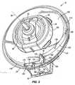
FIG. 1 is an exploded perspective view of a centrifugal blower assembly of the invention.FIG. 2 is a top perspective view of a motor housing of the centrifugal blower assembly of the invention.FIG. 3 is a top, partial cutaway view of the motor housing ofFIG. 2 .FIG. 4 is an assembled, cross-sectional view of the centrifugal blower assembly ofFIG. 1 - Before any embodiments of the invention are explained in detail, it is to be understood that the invention is not limited in its application to the details of construction and the arrangement of components set forth in the following description or illustrated in the following drawings. The invention is capable of other embodiments and of being practiced or of being carried out in various ways. Also, it is to be understood that the phraseology and terminology used herein is for the purpose of description and should not be regarded as limiting.
- With reference to
FIG. 1 , acentrifugal blower assembly 10 includes avolute 14, amotor 18 andmotor housing 22 supported by thevolute 14, and acentrifugal blower 26 drivably coupled to themotor 18 to create an airflow through thevolute 14. Thevolute 14 includes aninlet 30 and anoutlet 34 oriented substantially normal to theinlet 30, such that an airflow is drawn by thecentrifugal blower 26 through theinlet 30 in an axial direction with respect to anaxis 38 of rotation of thecentrifugal blower 26 and discharged through theoutlet 34 in a radial direction with respect to theaxis 38 of rotation of thecentrifugal blower 26. - In the illustrated construction of the
centrifugal blower assembly 10, thevolute 14 is formed of two pieces which, when assembled, define ascroll 42 within which the airflow created by theblower 26 flows. Alternatively, thevolute 14 may be formed from any of a number of different pieces or as a single piece. As is understood by one of ordinary skill in the art, thescroll 42 defines a progressively increasing cross-sectional area from the beginning of the scroll 42 (i.e., where the cross-sectional area of thescroll 42 is at a minimum value) leading to theoutlet 34 of the volute 14 (i.e., where the cross-sectional area of the scroll is at a maximum value) to facilitate expansion of the airflow as it flows from the beginning of thescroll 42 to theoutlet 34. - With reference to
FIG. 4 , themotor 18 is configured as an open-frameelectric motor 18 having anouter can 46, astator 48 consisting of a plurality of permanent magnets, anarmature 49 consisting of a plurality of windings, and anoutput shaft 50 co-rotating with thearmature 49 and protruding from thecan 46. As shown inFIG. 4 , a radial gap exists between thestator 48 and thearmature 49 through which an airflow may pass to cool the internal components of the motor 18 (e.g., thestator 48, thearmature 49, commutator brushes, etc.). Alternatively, theouter can 46 may be substantially closed, and themotor 18 may be configured as a can-style electric motor. - With continued reference to
FIG. 4 , themotor housing 22 couples themotor 18 to thevolute 14 and also maintains theoutput shaft 50 of the motor 18 (and therefore the centrifugal blower 26) in coaxial alignment with theinlet 30 of thevolute 14. Themotor 18 includes a plurality ofvibration isolation elements 54 positioned between theouter can 46 and themotor housing 22 to reduce the amount of vibration transferred from themotor 18 to themotor housing 22 and to coaxially align theoutput shaft 50 with theinlet 30 of thevolute 14. In the illustrated construction of theassembly 10, thevibration isolation elements 54 are configured as elastomeric (i.e., rubber) balls or spheres, and interconnected pairs ofelements 54 are supported on theouter can 46 by respective tabs 58 (only one of which is shown inFIG. 4 ). Alternatively, theelements 54 may have a different configuration than that shown inFIG. 4 . - The
motor housing 22 includes anupper portion 62 having a plurality of slots or pockets 66 (only one of which is shown inFIG. 4 ) spaced about thecentral axis 38 at equal or unequal intervals in which the respective pairs ofvibration isolation elements 54 are at least partially received. Themotor housing 22 also includes alower portion 70 coupled to the upper portion 62 (e.g., using a snap-fit, using fasteners, by welding, using adhesives, etc.) and having a corresponding plurality offingers 74 that are engaged with thelower element 54 in each of the pairs of,elements 54 to clamp the pairs ofelements 54 between theupper portion 62 and thelower portion 70 of themotor housing 22, thereby axially securing themotor 18 to themotor housing 22. - With continued reference to
FIG. 4 , a combination of the upper andlower portions motor housing 22 defines amotor support portion 102 having a first, at least partiallyopen end 230 and a second, closedend 234 defining thecentral axis 38 therebetween. Themotor support portion 102 includes acavity 238 in which themotor 18 is positioned. - With reference to
FIGS. 2 and4 , themotor housing 22 includes acooling air passageway 78 in fluid communication with thecavity 238 and aninlet 82 opening directly into thecooling air passageway 78. Themotor housing 22 also includes anoutlet 84, defined between aninterior wall 94 separating thepassageway 78 from themotor cavity 238 and thelower portion 70 of thehousing 22, fluidly communicating thepassageway 78 with thecavity 238. Thefirst end 230 of themotor housing 22 also includes a discharge opening 86 in facing relationship with the underside of thecentrifugal blower 26. As is described in greater detail below, during operation of thecentrifugal blower assembly 10, some of the airflow in thescroll 42 is diverted from thescroll 42 to thecooling air passageway 78 via theinlet 82. From theinlet 82, the airflow is directed through thecooling air passageway 78 toward abottom end 90 of themotor 18. The airflow then exits thepassageway 78 through theoutlet 84 and is redirected upwardly, around aninterior wall 94 of thehousing 22, through thecavity 238 toward atop end 98 of themotor 18. Because themotor 18 is configured as an open-frame motor 18, the airflow is allowed to pass through the interior of thecan 46 to cool the internal components (e.g., thestator 48, thearmature 49, commutator brushes, etc.) of themotor 18. The airflow through thecooling air passageway 78 and thecavity 238 is represented by the series of arrows A inFIG. 4 . The resultant heated airflow exits thehousing 22 through the discharge opening 86. Should a can-style motor be employed rather than the illustrated open-frame motor 18, the airflow may pass through the space or gap between the radially outermost surface of the can and a facing interior surface of the motor housing 22 (i.e., around the radially outermost surface of the can). - With reference to
FIG. 2 , themotor housing 22 also includes an upper axial-facingwall 106 surrounding and extending from themotor support portion 102. Thewall 106 is oriented substantially normal to thecentral axis 38 and is in facing relationship with thecentrifugal blower 26. The outer periphery of thetop end 98 of themotor 18 is substantially enclosed by the motor support portion 102 (FIG. 4 ). Themotor housing 22 further includes anouter wall 110 disposed adjacent and radially outwardly of thewall 106. Theouter wall 110 includes afirst portion 114 defining at least a portion of a cylinder 118 (FIG. 3 ) coaxial with thecentral axis 38, and asecond portion 122 spanning between theinlet 82 and the first portion 114 (FIG. 2 ). In the illustrated construction of thecentrifugal blower assembly 10, both the first andsecond portions outer wall 110 are oriented substantially normal to the upper axial-facingwall 106. Alternatively, either of theportions outer wall 110 may be oriented obliquely with respect to the upper axial-facingwall 106. - As shown in
FIGS. 2 and3 , thesecond portion 122 of thewall 110 deviates from thecylinder 118 in a direction toward thecentral axis 38. In the illustrated construction of thecentrifugal blower assembly 10, the first andsecond portions wall 110 are demarcated by a transition, schematically illustrated with adashed line 126, where thesecond portion 122 of thewall 110 deviates from thecylinder 118. In the illustrated construction of thecentrifugal blower assembly 10, the first andsecond portions wall 110 are blended together such that thetransition 126 does not appear as a distinct line. Thesecond portion 122 of thewall 110 includes an arcuate shape that may be defined by any of a number of different mathematical relationships with respect to the axis 38 (e.g., a continually decreasing radius having an origin coaxial with or offset from the axis 38). Alternatively, at least a portion of thesecond portion 122 of thewall 110 may include a planar or flat shape. As a further alternative, thetransition 126 may appear as a distinct line on thewall 110. - With reference to
FIG. 2 , themotor housing 22 also includes a lower axial-facing surface orwall 130 adjacent theouter wall 110. Thewall 130 is also oriented substantially normal to thesecond portion 122 of thewall 110. Further, thewall 130 is substantially parallel with the upper axial-facingwall 106 and is axially offset from thewall 130 toward thesecond end 234 of themotor support portion 102 in a direction parallel to thecentral axis 38. Alternatively, thewall 130 may be non-parallel with thewall 106. As is described in more detail below, a combination of thesecond portion 122 of theouter wall 110 and the lower axial-facingwall 130 define aninlet path 134 upstream of and leading toward theinlet 82 of the coolingair passageway 78. - With reference to
FIG. 4 , the coolingair passageway 78 is oriented generally parallel with thecentral axis 38 and is spaced or offset from thecentral axis 38. In the illustrated construction of thecentrifugal blower assembly 10, the coolingair passageway 78 includes four interconnectedorthogonal surfaces FIG. 4 ) imparting a substantially rectangular shape to the coolingair passageway 78. Alternatively, thesurfaces air passageway 78 may be shaped in any of a number of different ways. Thesurface 138 is defined by theinterior wall 94 and is adjacent an underside of the upper axially-facingwall 106. Thesurfaces respective edges FIG. 3 ). Theinlet 82 is disposed adjacent the upper axial-facing wall 106 (i.e., beneath thewall 106 from the point of view ofFIG. 4 ) and is at least partially defined by the twoedges centrifugal blower assembly 10, themotor housing 22 includes aramp 158 at least partially bounded by theedge 150 and anedge 162 of the lower axially-facingsurface 130. Alternatively, theramp 158 may be omitted, and theedge 150 may be shared between thesurface 142 and the lower axially-facingwall 130. - With reference to
FIG. 2 , in addition to being defined by theedges inlet 82 is also at least partially defined byopposite edges outer wall 110, and byrespective edges wall 106 that are oriented substantially normal to each other. As such, theinlet 82 is substantially L-shaped, such that an airflow (designated with arrow B;FIG. 3 ) may directly enter thepassageway 78 through afirst side 182 of theinlet 82, and another airflow (designated with arrow C) may directly enter thepassageway 78 through asecond side 186 of the inlet 82 (FIG. 2 ), in which therespective sides - In other words, the
inlet 82 is configured to permit entry of a generally tangential airflow (arrow B inFIG. 3 ) and a generally radial airflow (arrow C) directly into thepassageway 78. Although the tangential and radial airflows designated by arrows B and C, respectively, are shown oriented substantially normal to each other, one of ordinary skill in the art would understand that the airflows passing through the first andsecond sides inlet 82 may deviate from the illustrated directions. Accordingly, as used herein, a "tangential" airflow may be considered as any airflow swirling around thecentral axis 38 and flowing over theedge 150 prior to entering thepassageway 78. Likewise, as used herein, a "radial" airflow may be considered as any airflow flowing generally toward thecentral axis 38 and flowing over theedge 154 prior to entering thepassageway 78. In an alternative embodiment of theassembly 10, thesingle inlet 82 may be separated into two distinct openings coinciding with therespective sides - With reference to
FIG. 1 , thecentrifugal blower 26 includes ahub 194 coupled to theoutput shaft 50 of themotor 18. In the illustrated construction of thecentrifugal blower assembly 10, thehub 194 includes acentral bore 198 coaxial with theaxis 38 and sized to provide an interference fit with theoutput shaft 50 when coupled to the motor 18 (FIG. 4 ). The interference fit is sufficient to substantially prevent relative movement (i.e., in both a rotational direction and an axial direction) between theblower 26 and theoutput shaft 50. Alternatively, any of a number of different processes (e.g., welding, brazing, adhering, etc.) may be employed in place of the interference fit to rotationally and axially secure thehub 194 to theoutput shaft 50. As a further alternative, the tip of theoutput shaft 50 may be configured having a non-circular cross-section, and thecentral bore 198 may include a corresponding non-circular cross-section to fix theblower 26 for co-rotation with theoutput shaft 50. In conjunction with this alternative construction, a threaded aperture may be formed in the tip of theoutput shaft 50, and a threaded fastener (e.g., a bolt or a screw) may be received in thecentral bore 198 and the threaded aperture to axially secure thehub 194, and therefore thecentrifugal blower 26, to theoutput shaft 50. As yet another alternative, a separate adapter may be utilized to couple thehub 194 and theoutput shaft 50. - With reference to
FIGS. 1 and4 , thecentrifugal blower 26 includes anouter rim 202 that is concentric with thehub 194. As shown inFIG. 4 , thehub 194 is also axially spaced from theouter rim 202, rather than being co-planar with theouter rim 202. This allows at least a portion of themotor 18 to fit inside thecentrifugal blower 26. Alternatively, thehub 194 may be positioned coplanar with theouter rim 202, such that no portion of themotor 18 may fit inside thecentrifugal blower 26. - With reference to
FIGS. 1 and4 , thecentrifugal blower 26 also includes a plurality ofblades 210 coupled to theouter rim 202 and extending away from theouter rim 202 in a direction toward the top end of thecentrifugal blower 26 and substantially parallel with theaxis 38. Thecentrifugal blower 26 also includes aband 214 interconnecting the top edges of theblades 210. As discussed above, theblades 210 are oriented with respect to thehub 194 to draw an airflow into the middle of thecentrifugal blower 26 in a direction substantially parallel with theaxis 38, and discharge the airflow in a radial direction with respect to theaxis 38. - With reference to
FIG. 4 , theinlet 82 is entirely disposed within acylinder 190 coinciding with an outermost radius R of thecentrifugal blower 26. In the illustrated construction of thecentrifugal blower assembly 10, the outermost radius R coincides with the outermost radius of theband 214. Alternatively, the outermost radius R may coincide with other portions of the blower 26 (e.g., the rim 202). As a further alternative, a portion of theinlet 82 may be positioned outside thecylinder 190 coinciding with the outermost radius R of theblower 26. - With continued reference to
FIGS. 1 and4 , thecentrifugal blower 26 also includes a plurality ofspokes 218 interconnecting thehub 194 and theouter rim 202. Thespokes 218 structurally support theouter rim 202, theblades 210, and theband 214 on thehub 194. In addition, torque from themotor 18 is transferred from thehub 194 to theouter rim 202 via thespokes 218. As a result, thespokes 218 are both weight-bearing and load-carrying structural elements. Thecentrifugal blower 26 includes a plurality ofopenings 222 arranged about theaxis 38 and positioned between thehub 194 and theouter rim 202. Specifically, each of theopenings 222 is defined by a combination of thehub 194, theouter rim 202, and twoadjacent spokes 218. Theopenings 222 give the appearance that the middle of thecentrifugal blower 26 is "open," rather than having a solid plate interconnecting thehub 194 and theouter rim 202. Such an open configuration of theblower 26 is known in the art as an "open-hub"centrifugal blower 26. Alternatively, theblower 26 may be configured as a "closed-hub" centrifugal blower, in which theopenings 222 are omitted. - The
centrifugal blower 26 also includes a plurality of coolingribs 226 extending from therespective spokes 218 in a direction substantially parallel with theaxis 38, toward a bottom end of thecentrifugal blower 26. The illustratedblower 26 is integrally formed as a single piece (e.g., from a plastic material using a molding process). Alternatively, theblower 26 may be assembled from two or more pieces, and/or may be made from any of a number of different materials (e.g., a metal, a composite material, etc.). - In operation of the
centrifugal blower assembly 10, themotor 18 drives thecentrifugal blower 26 to create an airflow through thescroll 42. Most of the airflow created by thecentrifugal blower 26 flows through thescroll 42 toward theoutlet 34 of thevolute 14. Some of the airflow in thescroll 42, however, is diverted from thescroll 42 to the coolingair passageway 78 via theinlet 82. Particularly, theside 182 of theinlet 82 is oriented substantially normal to the direction of the airflow B as it follows the contour of the first andsecond portions FIGS. 2 and3 ). Thesecond portion 122 of thewall 110 diverges gradually toward thecentral axis 38 to substantially prevent any separation of the airflow B (FIG. 3 ) from thesecond portion 122 of theouter wall 110. In this manner, theinlet path 134 directs the tangential airflow B toward thecooling airflow passageway 78 and uses the dynamic pressure of the tangential airflow B within thevolute 42 to cool themotor 18. - The
second side 186 of theinlet 82 is oriented generally parallel to the tangential airflow B in thevolute 42 and cannot receive the airflow B in the same manner as thefirst side 182 of theinlet 82. However, the static pressure in thevolute 42 in the vicinity of thesecond side 186 of theinlet 82 is sufficient to induce the radial airflow C through thesecond side 186 of theinlet 82 and directly into the coolingair passageway 78 to provide additional cooling to themotor 18. - From the
inlet 82, the combined airflow (designated by the series of arrows A;FIG. 4 ) is directed through the coolingair passageway 78 toward thebottom end 90 of themotor 18. The airflow then exits thepassageway 78 through theoutlet 84 and is redirected upwardly, around theinterior wall 94 of thehousing 22, toward thetop end 98 of themotor 18. As the airflow moves upwardly toward thetop end 98 of themotor 18, the airflow flows through the interior of thecan 46 to cool the internal components (e.g., thestator 48, thearmature 49, commutator brushes, etc.) of themotor 18. The resultant heated airflow is drawn through thedischarge opening 86 by therotating cooling ribs 226. The heated airflow is subsequently re-introduced into theblades 210 of thecentrifugal blower 26 for recirculation into thescroll 42. Alternatively, when a closed-hub centrifugal blower is utilized in theassembly 10, the heated airflow passing through thedischarge opening 86 must flow around the lower plate of the closed-hub centrifugal blower prior to being recirculated into thescroll 42. - The cooling
ribs 226 create a region of relatively low pressure proximate thedischarge opening 86 during rotation of theblower 26. This, in conjunction with the dynamic pressure and the static pressure of the circulating airflow near theinlet 82 of the coolingair passageway 78, yields a larger pressure differential between theinlet 82 of the coolingair passageway 78 and thedischarge opening 86 than what would otherwise result in the absence of thecooling ribs 226. By increasing the pressure differential between theinlet 82 of the coolingair passageway 78 and thedischarge opening 86 in this manner, the flow rate of the airflow through the coolingair passageway 78 is increased, thereby enhancing the cooling effects on themotor 18. Alternatively, the coolingribs 226 may be omitted if the airflow in thevolute 42 that is generated by theblades 210 is sufficient to create a large enough pressure differential between theinlet 82 of the coolingair passageway 78 and thedischarge opening 86 to provide sufficient cooling of themotor 18. - Various features of the invention are set forth in the following claims.
Claims (11)
- A motor housing (22) for use with a centrifugal blower assembly (10), the motor housing (22) comprising:a motor support portion (102) defining a central axis (38) and including a first end (230) and a second end (234);a first wall (106) surrounding the motor support portion (102);a surface (146) offset from the first wall (106) toward the second end (234) in a direction parallel with the central axis (38);a cooling air passageway (78) oriented generally parallel with the central axis (38) and offset from the central axis (38); andan inlet (82), opening directly into the cooling air passageway (78), at least partially defined between the first wall (106) and the surface (146), wherein the inlet (82) is configured to permit entry of a tangential airflow (B) into the cooling air passageway (78), and wherein the inlet (82) is configured to permit entry of a radial airflow (C) into the cooling air passageway (78);characterized in that the motor housing (22) further includes a second wall (110) disposed adjacent and radially outwardly of the first wall (106), wherein the second wall (110) includesa first portion (114) defining at least a portion of a cylinder (118) coaxial with the central axis (38), anda second portion (122) spanning between the inlet (82) and the first portion (114), wherein the second portion (122) deviates from the cylinder (118) in a direction toward the central axis (38).
- The motor housing (22) of claim 1, wherein the cooling air passageway (78) is at least partially defined by a first surface at least partially bounded by a first edge, and a second surface at least partially bounded by a second edge oriented substantially normal to the first edge, wherein the inlet (82) is at least partially defined by the first and second edges.
- The motor housing (22) of claim 1, wherein the second portion (122) of the second wall (110) is arcuate.
- The motor housing (22) of claim 1, wherein the second portion (122) of the second wall (110) includes a third edge defining a portion of the inlet (82).
- The motor housing (22) of claim 4, further comprising a third wall (130) adjacent the second wall (110) and oriented substantially parallel with the first wall (106), the third wall (130) including the surface and a fourth edge, and a ramp (158) at least partially bounded by the first and fourth edges.
- The motor housing (22) of claim 4, wherein the second wall (110) includes a fourth edge at least partially defining a first side of the inlet (82).
- The motor housing (22) of claim 6, wherein the third edge of the second wall (110) defines a second side of the inlet (82).
- The motor housing (22) of claim 7, wherein the first wall (106) includes a fifth edge adjacent the third edge, and a sixth edge adjacent the fourth edge and oriented substantially normal to the fifth edge, wherein the fifth and sixth edges at least partially define the inlet (82).
- A centrifugal blower assembly (10) comprising:a volute;the motor housing (22) of any of claims 1-8;a motor (18) supported by the motor housing (22) and having an output shaft (50); anda centrifugal blower (26) coupled to the output shaft (50) for co-rotation with the output shaft (50).
- The centrifugal blower assembly (10) of claim 9, wherein the wall is in facing relationship with the centrifugal blower (26).
- The centrifugal blower assembly (10) of claim 9, wherein the centrifugal blower (26) defines an outermost radius (R), and wherein the inlet (82) is disposed within a cylinder (190) coinciding with the outermost radius (R) of the centrifugal blower (26).
Applications Claiming Priority (2)
| Application Number | Priority Date | Filing Date | Title |
|---|---|---|---|
| US12/700,026US8267674B2 (en) | 2010-02-04 | 2010-02-04 | Centrifugal blower assembly |
| PCT/US2011/023133WO2011097157A1 (en) | 2010-02-04 | 2011-01-31 | Centrifugal blower assembly |
Publications (2)
| Publication Number | Publication Date |
|---|---|
| EP2531731A1 EP2531731A1 (en) | 2012-12-12 |
| EP2531731B1true EP2531731B1 (en) | 2016-11-23 |
Family
ID=43781053
Family Applications (1)
| Application Number | Title | Priority Date | Filing Date |
|---|---|---|---|
| EP11702375.4AActiveEP2531731B1 (en) | 2010-02-04 | 2011-01-31 | Centrifugal blower assembly |
Country Status (6)
| Country | Link |
|---|---|
| US (1) | US8267674B2 (en) |
| EP (1) | EP2531731B1 (en) |
| KR (1) | KR101799123B1 (en) |
| CN (1) | CN102782333B (en) |
| BR (1) | BR112012019678A2 (en) |
| WO (1) | WO2011097157A1 (en) |
Families Citing this family (23)
| Publication number | Priority date | Publication date | Assignee | Title |
|---|---|---|---|---|
| DE102008042897A1 (en)* | 2008-10-16 | 2010-04-22 | Robert Bosch Gmbh | Blower device for a vehicle |
| US20110274568A1 (en)* | 2010-05-10 | 2011-11-10 | New Widetech Industries Co., Ltd. | Blower for a dehumidifier |
| US8998587B2 (en)* | 2011-12-16 | 2015-04-07 | Denso International America, Inc. | Blower motor cooling tube noise suppressor for ticking/chirping |
| DE102011090066A1 (en)* | 2011-12-29 | 2013-07-04 | Robert Bosch Gmbh | fan module |
| CN102588309A (en)* | 2012-03-07 | 2012-07-18 | 福州科拓贸易有限公司 | Air blower |
| DE102013109401A1 (en)* | 2013-08-02 | 2015-02-19 | Ebm-Papst Landshut Gmbh | Radial blower in a compact design |
| US9914542B2 (en)* | 2013-10-14 | 2018-03-13 | Hamilton Sundstrand Corporation | Ram air fan housing |
| JP6354309B2 (en)* | 2014-05-12 | 2018-07-11 | 株式会社デンソー | Blower device |
| CN106715922B (en)* | 2014-10-14 | 2018-12-28 | 松下知识产权经营株式会社 | Centrifugal blower and automobile equipped with the centrifugal blower |
| EP3037672B1 (en)* | 2014-12-22 | 2019-09-11 | Whirlpool EMEA S.p.A | Adapter in a suction device for a hood |
| CN105747989B (en) | 2015-01-06 | 2020-06-26 | 创科实业有限公司 | Axial fan vacuum cleaner |
| US9912207B2 (en)* | 2015-03-23 | 2018-03-06 | Regal Beloit America, Inc. | Electrical machine housing and methods of assembling the same |
| DE102015210647A1 (en)* | 2015-06-10 | 2016-12-15 | Mahle International Gmbh | centrifugal blower |
| DE202015009563U1 (en)* | 2015-09-24 | 2018-04-25 | Ebm-Papst St. Georgen Gmbh & Co. Kg | fan unit |
| JP6873622B2 (en)* | 2016-07-15 | 2021-05-19 | 三菱重工サーマルシステムズ株式会社 | Blower, air conditioner for vehicles |
| EP3376043B1 (en)* | 2017-03-16 | 2020-12-09 | LG Electronics Inc. | Motor fan |
| CN108626146B (en)* | 2017-03-17 | 2020-05-22 | 日本电产株式会社 | Air supply device and dust collector |
| JP6747402B2 (en)* | 2017-08-11 | 2020-08-26 | 株式会社デンソー | Blower |
| JP6635994B2 (en)* | 2017-09-13 | 2020-01-29 | シナノケンシ株式会社 | Blower |
| JP2021000852A (en)* | 2019-06-19 | 2021-01-07 | 株式会社デンソー | Air conditioning unit |
| CN214092394U (en)* | 2020-12-17 | 2021-08-31 | 中山大洋电机股份有限公司 | Direct current draught fan |
| DE112022003963T5 (en) | 2021-10-11 | 2024-07-04 | Milwaukee Electric Tool Corporation | BLOWER FOR A HANDHELD BLOWER |
| US12352274B2 (en) | 2022-03-21 | 2025-07-08 | Milwaukee Electric Tool Corporation | Axial blower |
Family Cites Families (27)
| Publication number | Priority date | Publication date | Assignee | Title |
|---|---|---|---|---|
| FR1376180A (en)* | 1962-12-21 | 1964-10-23 | Electrolux Ab | Cooling device for an electric motor-fan unit and assembly provided with said device |
| US4111615A (en)* | 1975-06-18 | 1978-09-05 | Matsushita Electric Industrial Company, Limited | Fluid exhausting device |
| US4184804A (en)* | 1975-10-10 | 1980-01-22 | Nippon Soken, Inc. | Rotary electric machine having a cooling fan |
| US4186317A (en)* | 1976-10-07 | 1980-01-29 | Sisk Hollis D | Endplate with cast-in baffle |
| JPS57148554A (en)* | 1981-03-06 | 1982-09-13 | Hitachi Ltd | Cooler for blower driving motor |
| CA2047576C (en)* | 1991-04-03 | 2002-09-10 | Robert Alan Colwell | Draft inducer blower motor mounting and cooling construction |
| US5814908A (en)* | 1996-04-30 | 1998-09-29 | Siemens Electric Limited | Blower wheel with axial inlet for ventilation |
| US5743721A (en)* | 1996-04-30 | 1998-04-28 | Itt Automotive Electrical Systems, Inc. | Blower assembly having integral air flow cooling duct |
| US5714819A (en)* | 1996-10-28 | 1998-02-03 | Ametek, Inc. | Motor having universal fan end bracket |
| US5944497A (en)* | 1997-11-25 | 1999-08-31 | Siemens Canada Limited | Fan assembly having an air directing member to cool a motor |
| US6166462A (en)* | 1998-05-04 | 2000-12-26 | Ametek, Inc. | Bypass motor/fan assembly having separate working air passages |
| IT1308475B1 (en)* | 1999-05-07 | 2001-12-17 | Gate Spa | FAN MOTOR, IN PARTICULAR FOR A HEAT EXCHANGER OF A VEHICLE |
| US6351046B1 (en)* | 2000-01-13 | 2002-02-26 | Delphi Technologies, Inc. | Compact dynamoelectric machine |
| US6561772B2 (en)* | 2001-04-03 | 2003-05-13 | Ametek, Inc. | Motor cooling fan housing with muffler |
| AUPR904301A0 (en)* | 2001-11-23 | 2001-12-20 | King, Peter John | Blower unit |
| KR100651684B1 (en)* | 2002-05-10 | 2006-11-30 | 한라공조주식회사 | Chiller of blower motor |
| US6802699B2 (en)* | 2002-06-06 | 2004-10-12 | Calsonic Kansei Corporation | Motor mounting structure |
| JP3981628B2 (en)* | 2002-11-28 | 2007-09-26 | 株式会社東芝 | Cooling pump, electrical equipment and personal computer |
| US6997686B2 (en)* | 2002-12-19 | 2006-02-14 | R & D Dynamics Corporation | Motor driven two-stage centrifugal air-conditioning compressor |
| FR2856852B1 (en)* | 2003-06-27 | 2006-09-29 | Asmo Co Ltd | AIR CONDITIONER ENGINE ASSEMBLY FOR VEHICLES |
| FR2859579B1 (en)* | 2003-09-10 | 2006-03-03 | Valeo Climatisation | DEVICE FOR SUPPORTING AN ELECTRIC MOTOR DRIVING A TURBINE, ESPECIALLY FOR AN APPARATUS FOR HEATING, VENTILATION AND / OR AIR CONDITIONING OF A MOTOR VEHICLE |
| US7037089B2 (en)* | 2004-05-25 | 2006-05-02 | Hsieh Hsin-Mao | Cooling fan having dual blade sets |
| US7118355B2 (en)* | 2005-02-04 | 2006-10-10 | Delphi Technologies, Inc. | Electric motor driven blower assembly with integral motor cooling duct |
| DE202005004274U1 (en)* | 2005-03-14 | 2006-07-27 | Ebm-Papst Landshut Gmbh | Electric motor-driven radial fan with IC |
| JP2007143207A (en)* | 2005-11-14 | 2007-06-07 | Asmo Co Ltd | Dynamo-electric machine and vehicle blower |
| JP4876841B2 (en)* | 2005-12-28 | 2012-02-15 | 株式会社デンソー | Blower |
| US20080044277A1 (en)* | 2006-08-15 | 2008-02-21 | Finkenbinder David B | Insert for fan-motor assembly |
- 2010
- 2010-02-04USUS12/700,026patent/US8267674B2/enactiveActive
- 2011
- 2011-01-31CNCN201180012391.3Apatent/CN102782333B/enactiveActive
- 2011-01-31WOPCT/US2011/023133patent/WO2011097157A1/enactiveApplication Filing
- 2011-01-31EPEP11702375.4Apatent/EP2531731B1/enactiveActive
- 2011-01-31KRKR1020127022994Apatent/KR101799123B1/enactiveActive
- 2011-01-31BRBR112012019678Apatent/BR112012019678A2/ennot_activeIP Right Cessation
Also Published As
| Publication number | Publication date |
|---|---|
| KR101799123B1 (en) | 2017-11-17 |
| CN102782333B (en) | 2015-07-29 |
| BR112012019678A2 (en) | 2016-05-03 |
| EP2531731A1 (en) | 2012-12-12 |
| WO2011097157A1 (en) | 2011-08-11 |
| CN102782333A (en) | 2012-11-14 |
| KR20120139727A (en) | 2012-12-27 |
| US20110189033A1 (en) | 2011-08-04 |
| US8267674B2 (en) | 2012-09-18 |
Similar Documents
| Publication | Publication Date | Title |
|---|---|---|
| EP2531731B1 (en) | Centrifugal blower assembly | |
| US20110116928A1 (en) | Open-hub centrifugal blower assembly | |
| US8651814B2 (en) | Axial flow fan with hub isolation slots | |
| US6789999B2 (en) | Center console dual centrifugal fan blower | |
| US10337522B2 (en) | Centrifugal compressor | |
| KR101019832B1 (en) | Centrifugal blower | |
| KR101990108B1 (en) | A cooling fan and seat cooling system having the same | |
| US8167562B2 (en) | Centrifugal fan and blower having the same | |
| AU2021101003A4 (en) | Blower | |
| US10473108B2 (en) | Blower motor assembly having air directing surface | |
| WO2017051521A1 (en) | Temperature conditioning unit, temperature conditioning system, and vehicle | |
| US20090180868A1 (en) | Blower unit | |
| US10495114B2 (en) | Blower | |
| US9989066B2 (en) | Low power and low noise fan-scroll with multiple split incoming air-streams | |
| GB2334756A (en) | Fan unit with two fans, guide vanes and tapering duct | |
| CN112303000B (en) | Fan assembly and air conditioning cabinet having the same | |
| JP2009133277A (en) | Centrifugal blower | |
| JPH0580597B2 (en) | ||
| JP2012193679A (en) | Electric blower |
Legal Events
| Date | Code | Title | Description |
|---|---|---|---|
| PUAI | Public reference made under article 153(3) epc to a published international application that has entered the european phase | Free format text:ORIGINAL CODE: 0009012 | |
| 17P | Request for examination filed | Effective date:20120904 | |
| AK | Designated contracting states | Kind code of ref document:A1 Designated state(s):AL AT BE BG CH CY CZ DE DK EE ES FI FR GB GR HR HU IE IS IT LI LT LU LV MC MK MT NL NO PL PT RO RS SE SI SK SM TR | |
| DAX | Request for extension of the european patent (deleted) | ||
| RAP1 | Party data changed (applicant data changed or rights of an application transferred) | Owner name:ROBERT BOSCH GMBH | |
| GRAP | Despatch of communication of intention to grant a patent | Free format text:ORIGINAL CODE: EPIDOSNIGR1 | |
| INTG | Intention to grant announced | Effective date:20160620 | |
| GRAS | Grant fee paid | Free format text:ORIGINAL CODE: EPIDOSNIGR3 | |
| GRAA | (expected) grant | Free format text:ORIGINAL CODE: 0009210 | |
| AK | Designated contracting states | Kind code of ref document:B1 Designated state(s):AL AT BE BG CH CY CZ DE DK EE ES FI FR GB GR HR HU IE IS IT LI LT LU LV MC MK MT NL NO PL PT RO RS SE SI SK SM TR | |
| REG | Reference to a national code | Ref country code:GB Ref legal event code:FG4D | |
| REG | Reference to a national code | Ref country code:CH Ref legal event code:EP | |
| REG | Reference to a national code | Ref country code:IE Ref legal event code:FG4D | |
| REG | Reference to a national code | Ref country code:AT Ref legal event code:REF Ref document number:848174 Country of ref document:AT Kind code of ref document:T Effective date:20161215 | |
| REG | Reference to a national code | Ref country code:DE Ref legal event code:R096 Ref document number:602011032656 Country of ref document:DE | |
| REG | Reference to a national code | Ref country code:FR Ref legal event code:PLFP Year of fee payment:7 | |
| PG25 | Lapsed in a contracting state [announced via postgrant information from national office to epo] | Ref country code:LV Free format text:LAPSE BECAUSE OF FAILURE TO SUBMIT A TRANSLATION OF THE DESCRIPTION OR TO PAY THE FEE WITHIN THE PRESCRIBED TIME-LIMIT Effective date:20161123 | |
| REG | Reference to a national code | Ref country code:LT Ref legal event code:MG4D | |
| REG | Reference to a national code | Ref country code:NL Ref legal event code:MP Effective date:20161123 | |
| REG | Reference to a national code | Ref country code:AT Ref legal event code:MK05 Ref document number:848174 Country of ref document:AT Kind code of ref document:T Effective date:20161123 | |
| PG25 | Lapsed in a contracting state [announced via postgrant information from national office to epo] | Ref country code:NO Free format text:LAPSE BECAUSE OF FAILURE TO SUBMIT A TRANSLATION OF THE DESCRIPTION OR TO PAY THE FEE WITHIN THE PRESCRIBED TIME-LIMIT Effective date:20170223 Ref country code:NL Free format text:LAPSE BECAUSE OF FAILURE TO SUBMIT A TRANSLATION OF THE DESCRIPTION OR TO PAY THE FEE WITHIN THE PRESCRIBED TIME-LIMIT Effective date:20161123 Ref country code:LT Free format text:LAPSE BECAUSE OF FAILURE TO SUBMIT A TRANSLATION OF THE DESCRIPTION OR TO PAY THE FEE WITHIN THE PRESCRIBED TIME-LIMIT Effective date:20161123 Ref country code:SE Free format text:LAPSE BECAUSE OF FAILURE TO SUBMIT A TRANSLATION OF THE DESCRIPTION OR TO PAY THE FEE WITHIN THE PRESCRIBED TIME-LIMIT Effective date:20161123 Ref country code:GR Free format text:LAPSE BECAUSE OF FAILURE TO SUBMIT A TRANSLATION OF THE DESCRIPTION OR TO PAY THE FEE WITHIN THE PRESCRIBED TIME-LIMIT Effective date:20170224 | |
| PGFP | Annual fee paid to national office [announced via postgrant information from national office to epo] | Ref country code:FR Payment date:20170124 Year of fee payment:7 | |
| PG25 | Lapsed in a contracting state [announced via postgrant information from national office to epo] | Ref country code:FI Free format text:LAPSE BECAUSE OF FAILURE TO SUBMIT A TRANSLATION OF THE DESCRIPTION OR TO PAY THE FEE WITHIN THE PRESCRIBED TIME-LIMIT Effective date:20161123 Ref country code:RS Free format text:LAPSE BECAUSE OF FAILURE TO SUBMIT A TRANSLATION OF THE DESCRIPTION OR TO PAY THE FEE WITHIN THE PRESCRIBED TIME-LIMIT Effective date:20161123 Ref country code:AT Free format text:LAPSE BECAUSE OF FAILURE TO SUBMIT A TRANSLATION OF THE DESCRIPTION OR TO PAY THE FEE WITHIN THE PRESCRIBED TIME-LIMIT Effective date:20161123 Ref country code:BE Free format text:LAPSE BECAUSE OF NON-PAYMENT OF DUE FEES Effective date:20170131 Ref country code:ES Free format text:LAPSE BECAUSE OF FAILURE TO SUBMIT A TRANSLATION OF THE DESCRIPTION OR TO PAY THE FEE WITHIN THE PRESCRIBED TIME-LIMIT Effective date:20161123 Ref country code:PT Free format text:LAPSE BECAUSE OF FAILURE TO SUBMIT A TRANSLATION OF THE DESCRIPTION OR TO PAY THE FEE WITHIN THE PRESCRIBED TIME-LIMIT Effective date:20170323 Ref country code:HR Free format text:LAPSE BECAUSE OF FAILURE TO SUBMIT A TRANSLATION OF THE DESCRIPTION OR TO PAY THE FEE WITHIN THE PRESCRIBED TIME-LIMIT Effective date:20161123 Ref country code:PL Free format text:LAPSE BECAUSE OF FAILURE TO SUBMIT A TRANSLATION OF THE DESCRIPTION OR TO PAY THE FEE WITHIN THE PRESCRIBED TIME-LIMIT Effective date:20161123 | |
| PGFP | Annual fee paid to national office [announced via postgrant information from national office to epo] | Ref country code:GB Payment date:20170125 Year of fee payment:7 | |
| PG25 | Lapsed in a contracting state [announced via postgrant information from national office to epo] | Ref country code:EE Free format text:LAPSE BECAUSE OF FAILURE TO SUBMIT A TRANSLATION OF THE DESCRIPTION OR TO PAY THE FEE WITHIN THE PRESCRIBED TIME-LIMIT Effective date:20161123 Ref country code:SK Free format text:LAPSE BECAUSE OF FAILURE TO SUBMIT A TRANSLATION OF THE DESCRIPTION OR TO PAY THE FEE WITHIN THE PRESCRIBED TIME-LIMIT Effective date:20161123 Ref country code:RO Free format text:LAPSE BECAUSE OF FAILURE TO SUBMIT A TRANSLATION OF THE DESCRIPTION OR TO PAY THE FEE WITHIN THE PRESCRIBED TIME-LIMIT Effective date:20161123 Ref country code:CZ Free format text:LAPSE BECAUSE OF FAILURE TO SUBMIT A TRANSLATION OF THE DESCRIPTION OR TO PAY THE FEE WITHIN THE PRESCRIBED TIME-LIMIT Effective date:20161123 Ref country code:DK Free format text:LAPSE BECAUSE OF FAILURE TO SUBMIT A TRANSLATION OF THE DESCRIPTION OR TO PAY THE FEE WITHIN THE PRESCRIBED TIME-LIMIT Effective date:20161123 | |
| REG | Reference to a national code | Ref country code:DE Ref legal event code:R097 Ref document number:602011032656 Country of ref document:DE | |
| PG25 | Lapsed in a contracting state [announced via postgrant information from national office to epo] | Ref country code:SM Free format text:LAPSE BECAUSE OF FAILURE TO SUBMIT A TRANSLATION OF THE DESCRIPTION OR TO PAY THE FEE WITHIN THE PRESCRIBED TIME-LIMIT Effective date:20161123 Ref country code:BE Free format text:LAPSE BECAUSE OF FAILURE TO SUBMIT A TRANSLATION OF THE DESCRIPTION OR TO PAY THE FEE WITHIN THE PRESCRIBED TIME-LIMIT Effective date:20161123 Ref country code:IT Free format text:LAPSE BECAUSE OF FAILURE TO SUBMIT A TRANSLATION OF THE DESCRIPTION OR TO PAY THE FEE WITHIN THE PRESCRIBED TIME-LIMIT Effective date:20161123 Ref country code:BG Free format text:LAPSE BECAUSE OF FAILURE TO SUBMIT A TRANSLATION OF THE DESCRIPTION OR TO PAY THE FEE WITHIN THE PRESCRIBED TIME-LIMIT Effective date:20170223 | |
| REG | Reference to a national code | Ref country code:CH Ref legal event code:PL | |
| PG25 | Lapsed in a contracting state [announced via postgrant information from national office to epo] | Ref country code:MC Free format text:LAPSE BECAUSE OF FAILURE TO SUBMIT A TRANSLATION OF THE DESCRIPTION OR TO PAY THE FEE WITHIN THE PRESCRIBED TIME-LIMIT Effective date:20161123 | |
| PLBE | No opposition filed within time limit | Free format text:ORIGINAL CODE: 0009261 | |
| STAA | Information on the status of an ep patent application or granted ep patent | Free format text:STATUS: NO OPPOSITION FILED WITHIN TIME LIMIT | |
| PG25 | Lapsed in a contracting state [announced via postgrant information from national office to epo] | Ref country code:CH Free format text:LAPSE BECAUSE OF NON-PAYMENT OF DUE FEES Effective date:20170131 Ref country code:LI Free format text:LAPSE BECAUSE OF NON-PAYMENT OF DUE FEES Effective date:20170131 | |
| 26N | No opposition filed | Effective date:20170824 | |
| REG | Reference to a national code | Ref country code:IE Ref legal event code:MM4A | |
| PG25 | Lapsed in a contracting state [announced via postgrant information from national office to epo] | Ref country code:LU Free format text:LAPSE BECAUSE OF NON-PAYMENT OF DUE FEES Effective date:20170131 Ref country code:SI Free format text:LAPSE BECAUSE OF FAILURE TO SUBMIT A TRANSLATION OF THE DESCRIPTION OR TO PAY THE FEE WITHIN THE PRESCRIBED TIME-LIMIT Effective date:20161123 | |
| PG25 | Lapsed in a contracting state [announced via postgrant information from national office to epo] | Ref country code:IE Free format text:LAPSE BECAUSE OF NON-PAYMENT OF DUE FEES Effective date:20170131 | |
| GBPC | Gb: european patent ceased through non-payment of renewal fee | Effective date:20180131 | |
| PG25 | Lapsed in a contracting state [announced via postgrant information from national office to epo] | Ref country code:MT Free format text:LAPSE BECAUSE OF NON-PAYMENT OF DUE FEES Effective date:20170131 | |
| PG25 | Lapsed in a contracting state [announced via postgrant information from national office to epo] | Ref country code:FR Free format text:LAPSE BECAUSE OF NON-PAYMENT OF DUE FEES Effective date:20180131 | |
| REG | Reference to a national code | Ref country code:FR Ref legal event code:ST Effective date:20180928 | |
| PG25 | Lapsed in a contracting state [announced via postgrant information from national office to epo] | Ref country code:GB Free format text:LAPSE BECAUSE OF NON-PAYMENT OF DUE FEES Effective date:20180131 | |
| PG25 | Lapsed in a contracting state [announced via postgrant information from national office to epo] | Ref country code:HU Free format text:LAPSE BECAUSE OF FAILURE TO SUBMIT A TRANSLATION OF THE DESCRIPTION OR TO PAY THE FEE WITHIN THE PRESCRIBED TIME-LIMIT; INVALID AB INITIO Effective date:20110131 | |
| PG25 | Lapsed in a contracting state [announced via postgrant information from national office to epo] | Ref country code:CY Free format text:LAPSE BECAUSE OF NON-PAYMENT OF DUE FEES Effective date:20161123 | |
| PG25 | Lapsed in a contracting state [announced via postgrant information from national office to epo] | Ref country code:MK Free format text:LAPSE BECAUSE OF FAILURE TO SUBMIT A TRANSLATION OF THE DESCRIPTION OR TO PAY THE FEE WITHIN THE PRESCRIBED TIME-LIMIT Effective date:20161123 | |
| PG25 | Lapsed in a contracting state [announced via postgrant information from national office to epo] | Ref country code:TR Free format text:LAPSE BECAUSE OF FAILURE TO SUBMIT A TRANSLATION OF THE DESCRIPTION OR TO PAY THE FEE WITHIN THE PRESCRIBED TIME-LIMIT Effective date:20161123 | |
| PG25 | Lapsed in a contracting state [announced via postgrant information from national office to epo] | Ref country code:AL Free format text:LAPSE BECAUSE OF FAILURE TO SUBMIT A TRANSLATION OF THE DESCRIPTION OR TO PAY THE FEE WITHIN THE PRESCRIBED TIME-LIMIT Effective date:20161123 Ref country code:IS Free format text:LAPSE BECAUSE OF FAILURE TO SUBMIT A TRANSLATION OF THE DESCRIPTION OR TO PAY THE FEE WITHIN THE PRESCRIBED TIME-LIMIT Effective date:20170323 | |
| PGFP | Annual fee paid to national office [announced via postgrant information from national office to epo] | Ref country code:DE Payment date:20250317 Year of fee payment:15 |