EP2529853B1 - Marking method and punch press machine with a marking tool - Google Patents
Marking method and punch press machine with a marking toolDownload PDFInfo
- Publication number
- EP2529853B1 EP2529853B1EP11737145.0AEP11737145AEP2529853B1EP 2529853 B1EP2529853 B1EP 2529853B1EP 11737145 AEP11737145 AEP 11737145AEP 2529853 B1EP2529853 B1EP 2529853B1
- Authority
- EP
- European Patent Office
- Prior art keywords
- marking
- work
- tool
- axis direction
- rotating tool
- Prior art date
- Legal status (The legal status is an assumption and is not a legal conclusion. Google has not performed a legal analysis and makes no representation as to the accuracy of the status listed.)
- Not-in-force
Links
Images


Classifications
- B—PERFORMING OPERATIONS; TRANSPORTING
- B21—MECHANICAL METAL-WORKING WITHOUT ESSENTIALLY REMOVING MATERIAL; PUNCHING METAL
- B21C—MANUFACTURE OF METAL SHEETS, WIRE, RODS, TUBES, PROFILES OR LIKE SEMI-MANUFACTURED PRODUCTS OTHERWISE THAN BY ROLLING; AUXILIARY OPERATIONS USED IN CONNECTION WITH METAL-WORKING WITHOUT ESSENTIALLY REMOVING MATERIAL
- B21C51/00—Measuring, gauging, indicating, counting, or marking devices specially adapted for use in the production or manipulation of material in accordance with subclasses B21B - B21F
- B21C51/005—Marking devices
- B—PERFORMING OPERATIONS; TRANSPORTING
- B23—MACHINE TOOLS; METAL-WORKING NOT OTHERWISE PROVIDED FOR
- B23C—MILLING
- B23C2220/00—Details of milling processes
Definitions
- the present inventionrelates to a method for marking on a surface of a plate-like work by a turret punch press machine according to the preamble of claim 1 and to a punch press machine for conducting said method according to the preamble of claim 5 (see for example JP-A-2004 050346 ).
- Patent Document 1disclosed is an apparatus that utilizes a die that includes a number of marking dies as marking tools.
- this apparatussince various markings on an upper surface of the work are to be made by the marking dies, various types of marking dies are needed. Therefore, configuration of the die becomes complicated.
- a penis provided as a marking die, and disclosed is an apparatus in which markings on an upper surface of a work are made by the pen. Therefore, it is needed to control a remaining amount and drying of inks supplied to the pen.
- laser markingis known as a conventional marking method.
- a laser oscillator and a laser working headmust be needed additionally.
- a plate-like work worked by a punch press machinemay have a film made of resin such as vinyl on its surface as a protection film. With respect to such a work, it is generally done to peel the protection film from a product cut away from the work. Therefore, upon working the work by a punch press machine, if marking is made on a protection film, marking is done by using marking dies, or laser marking is done, marking residue may remain on a surface of a product.
- ink controlmay be needed as explained above, and also it is needed to select an ink suitable for a protection film on a work in some cases.
- marking on a surface of a workalso can be done by working such as cutting, grinding or the like by use of a rotating work tool included in a punch press machine.
- a marking amount (marking width) at a start position or an end position of markingbecomes larger than a marking amount (marking width) while the rotating work took is being moved relatively to the work, so that its appearance may be inferior (their marking widths become different from each other).
- the protection filmis torn, so that residue due to marking may remain on a surface of the work at a start position or an end position of marking.
- the methodmay further comprises: keeping a rotational speed of a rotating tool for marking to a desired rotational speed; and starting a relative movement of the work in an X-axis direction and/or in a Y-axis direction relative to the rotating tool at a same time of contacting a spherical portion of the rotating tool with the surface of the work.
- the workmay have a protection film capable of being peeled away on its surface.
- a second aspect of the present inventionprovides a punch press machine with the features of claim 5.
- the punch pressmay comprise a cylindrical tool body detachably and vertically movably attached to an upper die holder of a punch press machine; a rotational drive unit provided above the tool body; a hollow rotary shaft rotated by the rotational drive unit; a chuck vertically movably provided at a lower portion of the hollow rotary shaft and biased downward; and the rotating tool that includes a spherical portion for marking at a lower end thereof, wherein the rotating tool is detachably held by the chuck.
- a processing amount at a marking start position and a marking end position and a processing amount per a unit length of a marked lineare made almost constant. Therefore, a width of the marked line is almost made constant over its entire length.
- a protection filmis provided on a surface of a work and marking is processed on the protection film by a rotating tool, it can be prevented that the rotating tool tears the protection film and reaches to the surface of the work, so that no unfavorable marking is left on the work after peeling away the protection film.
- the punch press machine 1for working such as punching on a plate-like work W.
- the punch press machine 1includes a frame 3 as generally known.
- the frame 3is constructed integrally by an upper frame 3U and a lower frame 3L.
- an upper turret (upper die holder) 5Uis provided horizontally-rotatably.
- a lower turret (lower die holder) 51is provided horizontally-rotatably.
- plural punch attachment holes 5Hare provided, and punches P are replaceably installed to the punch attachment holes 5H.
- punches Pare replaceably installed to the punch attachment holes 5H.
- plural die attachment holes(not shown) corresponding to the upper turret 5U are provided, and replaceable dies D corresponding to the punches P are provided in the die attachment holes.
- a striker 7is provided that strikes a punch head of a punch P set at a work position by rotations of the upper and lower turrets 5U and 5L.
- the striker 7is moved vertically by a ram driver 9.
- the ram driver 9is, for example, a crank mechanism, a link mechanism or a ball screw mechanism that is rotated by a fluid pressure cylinder or a servomotor.
- a vertical position of the striker 7 to an original positionis constantly detected by a vertical position detector 93 (see Fig. 3 ) such as a rotary encoder.
- the punch press machine 1includes a moving and positioning unit 11 that moves a work W in X- and Y-axis directions relatively to the punch P and the die D set at the work position (position below the striker 7) to set its position, and a work table 13 that movably supports the work W.
- the moving and positioning unit 11includes a carriage base 17 that can move in the Y-axis direction (horizontal direction in Fig. 1 ) along guide rails 15 provided on the lower frame 5L.
- the carriage base 17is moved in the Y-axis direction by rotation of a Y-axis servomotor (not shown) and then its position is set, and extended in the X-axis direction (vertical direction in Fig. 1 ) perpendicularly intersecting with the Y-axis direction.
- the carriage base 17includes a carriage 19 that is moved in the X-axis direction by rotation of an X-axis servomotor (not shown) and then its position is set.
- the carriage 19includes plural work clamps 21 for clamping the work W. Each position of the work clamps 21 can be adjusted in the X-axis direction.
- the carriage base 17is moved in the Y-axis direction and then its position is set and the carriage 19 is moved in the X-axis direction and then its position is set, so that the work W clamped by the work clamps 21 is moved in the X- and Y-axis directions and then its position is set to set a to-be-worked portion on the work W at the work position (position of the punch P and the die D).
- the punch press machine 1includes a controller 23 such as a CNC controller.
- the controller 23mainly executes a rotation control of the upper and lower turrets 5U and 5L, a movement control of the moving and positioning unit 11, and a strike control of the striker 7.
- a marking tool 25 in the present embodimentis used by being attached to the punch attachment hole 5H on the upper turret 5U as a substitute for one punch P attached on the upper turret (upper holder) 5U, as shown in Fig. 2 .
- the marking tool 25includes a cylindrical tool body 27 similarly to a conventional punch P.
- the tool body 27is detachable to the punch attachment hole 5H, and supported in a state where it is plunged into the punch attachment hole 5H.
- a cylindrical upper body 31is coupled with an upper portion of the tool body 27 by a fastener 29 such as a cap nut.
- a fluid pressure motor (rotary drive unit) 33such as an air motor is vertically movably housed in the upper body 31.
- a head member 35is vertically movably supported at an upper portion of the upper body 31 in order to support the fluid pressure motor 33 vertically movably in the upper body 31. Namely, the head member 35 is supported while being biased upward by a coil spring (elastic member) 37 attached between the upper body 31 and the head member 35. An upward movement of the head body 35 is restricted by plural stopper bolts 39 whose lower ends are screw-mounted into the upper body 31. The fluid pressure motor 33 and the head member 35 are jointed to each other at a screw-joint portion 41.
- the head member 35is provided with a connection hole 35H connected to a supply hole 7H formed on the striker 7.
- the connection hole 35His connected to the fluid pressure motor 33.
- the supply hole 7Hsupplies oil mists to the punch P.
- an open-close valve 47such as a solenoid valve and an ejector 49 are provided sequentially from the air source 43.
- a connection path 53 connected to an oil tank 51is connected to the ejector 49.
- An open-close valve 55is provided on the connection path 53.
- a hollow rotary shaft 63is provided rotatably via plural bearings 61. Rotation of the fluid pressure motor 33 is transmitted to a marking pin (rotating tool) 57 of the marking tool 25 via the hollow rotary shaft 63.
- An upper portion of the hollow rotary shaft 63is coupled with a rotary shaft 67 of the fluid pressure motor 33 by a coupling pin 65, so that the hollow rotary shaft 63 rotates integrally with the rotary shaft 67.
- the coupling pin 65perpendicularly intersects with a shaft center of the hollow rotary shaft 63, and its both ends are fixed to the hollow rotary shaft 63.
- a middle of the coupling pin 65is coupled with a slit 67S axially formed at an end of the rotary shaft 67.
- a vertically movable chuck 69is provided at a lower portion of the hollow rotary shaft 63 while being biased downward.
- the marking pin 57is detachably attached to the chuck 69.
- the chuck 69 in the present embodimentis a collet chuck.
- a shank 71Sthat is an upper portion of a chuck main body 71 of the chuck 69 is plunged into the hollow rotary shaft 63 vertically movably but unrotatably.
- a ring spacer 73that has a slightly larger diameter than a diameter of the shank 71S is attached onto an upper surface of the shank 71S by a bolt 75.
- a coil spring (elastic member) 79is provided, while being compressed, between a spring seat 77 contacted with a lower end surface of the rotary shaft 67 and a head of the bolt 75.
- the shank 71Sis meshed with the hollow rotary shaft 63 by splines or keys, and continuously biased downward by the coil spring 79. Note that, since the spacer 73 is contacted with a stepped portion of the hollow rotary shaft 63, the chuck main body 71 is prevented from dropping off.
- a large diameter portion 81 in which a tapered hole is formedis provided at a lower portion of the chuck main body 71.
- a collet 83 for holding the marking pin 57is housed in the tapered hole.
- a nut 85is screwed with an outer circumferential surface of the large diameter portion 81, and, when the nut 85 is fastened, the collet 83 fixes the marking pin 57.
- a spherical portion 57Sis formed at a distal end (lower end) of the marking pin 57, and the spherical portion 57S engraves markings on a surface of the work W. Hard fine particles such as diamonds are provided on the spherical portion 57S.
- a markingis engraved by spinning the marking pin 57 while contacting the spherical portion 57S with the surface of the work W and moving the spherical portion 57S relatively to the work W to draw a line on the surface of the work W.
- an unfavorable circular markinghaving a diameter larger than a width of the line may be left at a start position (marking start position) and an end position (marking end position) of the marking.
- an unfavorable markingmay be left on the surface of the work W after peeling away the protection film. Improvement of marking quality that can prevent these unfavorable markings is desired.
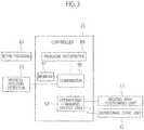
- the controller 23includes a program interpreter 89 and a comparator 95, as shown in Fig. 3 .
- the program interpreter 89interprets a work program 87 input thereto.
- the comparator 95compares, in a case where a marking process is found in the work program interpreted by the program interpreter 89, a preset value preset in a memory 91 with a detected value of the vertical position detector 93 that detects the vertical position of the striker 7.
- the controller 23includes an operational command output unit 97 that outputs an operational command concurrently to the moving and positioning unit 11 and the rotational drive unit 33 when the preset value is equal to the detected value mentioned above.
- the preset value preset in the memory 91is a value corresponding to a stroke amount from a position at which the striker 7 starts moving downward from its top dead center (or its reference position when lifted up) to become contacted with the head member 35 to a position at which the spherical portion 57S of the marking pin 57 becomes contacted with the upper surface (the surface) of the work W while the marking tool is moved downward against a lifter spring 99 (see Fig. 2 ).
- the preset value preset in the memory 91is (S1 + S2 + ⁇ ).
- ⁇is a correction value corresponding to thickness tolerance when the work W is made, and can take zero. The value ⁇ is determined by previously measuring a thickness of the work W.
- step S1the work program is interpreted by the program interpreter 89 (step S1). Then, if a marking process is found in the work program (YES in step S2), a to-be-worked portion of the work W is positioned in association with the marking tool 25 previously positioned at the work position (step S3) and the striker 7 is moved downward by the ram driver 9 (step S4) .
- the position of the striker 7 moved downward from its reference positionis detected by the vertical position detector 93, and the comparator 95 compares the detected value by the vertical position detector 93 with the preset value stored in the memory 91. If the detected value is equal to the preset value (YES in step S5), it is judged that the spherical portion 57S of the marking pin 57 is contacted with the upper surface of the work W and a downward motion of the striker 7 is stopped (step S6).
- the coil spring 79when the spherical portion 57S is contacted with the upper surface of the work W, the coil spring 79 is slightly compressed so as to absorb an error, a minor error in the preset value can be compensated. Namely, is can be done to preset the preset value slightly large, so that the spherical portion 57S can be contacted with the upper surface of the work W unfailingly.
- step S7When the striker 7 and the marking tool 25 are moved downward to the preset position previously set, the operational command is output from the operational command output unit 97 to the moving and positioning unit 11 and the rotational drive unit 33. As a result, spinning of the marking pin 57 is started and traveling thereof for marking on the work W is concurrently started, so that marking is processed (step S7).
- the marking start position(start position) is not processed more than a portion of drawing a line, so that no unfavorable circular marking having a diameter larger than a width of the line is left at the marking start position.
- a time needed for the marking pin 57 to reach a desired rotational speedis almost equal to a time needed for the work W to reach a desired moving speed. Therefore, a moving speed of the work W accelerates to the desired moving speed while a rotational speed of the marking pin 57 accelerates to the desired rotational speed.
- a processing amount per a unit length of a marked line by the marking pin 57 during these accelerationsis almost equal to a processing amount per a unit length of a marked line while a moving speed of the work W is the desired moving speed and the a rotational speed of the marking pin 57 is the desired rotational speed. Therefore, a width of the marked line during the accelerations is almost equal to a line width while a moving speed of the work W is the desired moving speed and the rotational speed of the marking pin 57 is the desired rotational speed.
- the processing amount in the one segmentbecomes larger than that in the other segments and thereby its line width becomes bold, because the marking pin 57 is biased downward by the coil spring 79. Therefore, in a case where the moving speed of the work W relative to the marking pin 57 is constant, it is preferable that the contact time of the work W with the marking pin 57 per a unit length of a marked line is constant. Namely, it is preferable that a processing amount per a unit length of a marked line is kept constant over an entire length of the marked line.
- the processing amount by the marking pin 57 at the marking start positionis almost equal to a processing amount at a given position on the marked line, and the processing amount per a unit length of the marked line is also constant, so that a width of the marked line becomes constant over its entire length.
- step S8the marking process is finished. If the marking end position is positioned outside the work W or outside a product, it doesn't become a problem to continue spinning of the marking pin 57 at the marking end position in step S8. However, if the marking end position is positioned upon a product, the relative movement of the work W and the spinning of the marking pin 57 are stopped concurrently. Alternatively, in step S8, the marking pin 57 is separated from the work W at the same time when the relative movement of the work W is stopped. According to these, no unfavorable circular marking having a diameter larger than a width of the line is left at the marking end position.
- the marking pin 57is contacted with the work W, the movement of the work W and the spinning of the marking pin 57 is concurrently started, and the movement of the work W and the spinning of the marking pin 57 is concurrently ended (alternatively, the marking pin 57 is separated from the work W), so that no unfavorable circular marking is left at the marking start position and the marking end position on the work W having a thin protection film on its surface. Namely, even if the protection film is extremely thin, marking can be processed without tearing the protection film (without penetrating the protection film). Therefore, no unfavorable circular marking is left on a surface of a product.
- the rotary drive unit 33 in the present embodimentis a fluid pressure motor, it may be a servomotor. In addition, it may be done that the relative movement of the work W in the X-axis and/or Y-axis direction is started at the same time when the marking tool 25 being spun at a desired rotational speed is contacted with the work W.
Landscapes
- Engineering & Computer Science (AREA)
- Mechanical Engineering (AREA)
- Shaping Metal By Deep-Drawing, Or The Like (AREA)
- Punching Or Piercing (AREA)
- Milling Processes (AREA)
Description
- The present invention relates to a method for marking on a surface of a plate-like work by a turret punch press machine according to the preamble of claim 1 and to a punch press machine for conducting said method according to the preamble of claim 5 (see for example
JP-A-2004 050346 - Conventionally, when punching a plate-like work in a punch press machine and so on, marking on a cutout piece (product) punched away from the work may be processed (see Patent Documents 1 and 2 listed below).
- Patent Document 1: Japanese Patent Application Laid-Open No.
H3-90227 - Patent Document 2: Japanese Patent Application Laid-Open No.
2005-34950 - In the above Patent Document 1, disclosed is an apparatus that utilizes a die that includes a number of marking dies as marking tools. In this apparatus, since various markings on an upper surface of the work are to be made by the marking dies, various types of marking dies are needed. Therefore, configuration of the die becomes complicated.
- In the above Patent Document 2, a pen is provided as a marking die, and disclosed is an apparatus in which markings on an upper surface of a work are made by the pen. Therefore, it is needed to control a remaining amount and drying of inks supplied to the pen.
- In addition, laser marking is known as a conventional marking method. In this case, a laser oscillator and a laser working head must be needed additionally.
- A plate-like work worked by a punch press machine may have a film made of resin such as vinyl on its surface as a protection film. With respect to such a work, it is generally done to peel the protection film from a product cut away from the work. Therefore, upon working the work by a punch press machine, if marking is made on a protection film, marking is done by using marking dies, or laser marking is done, marking residue may remain on a surface of a product.
- If marking is done by a pen as disclosed in the above Patent Document 2, ink control may be needed as explained above, and also it is needed to select an ink suitable for a protection film on a work in some cases.
- In addition, marking on a surface of a work also can be done by working such as cutting, grinding or the like by use of a rotating work tool included in a punch press machine. However, in a case of working on a surface of a work by use of a rotational work tool, a marking amount (marking width) at a start position or an end position of marking becomes larger than a marking amount (marking width) while the rotating work took is being moved relatively to the work, so that its appearance may be inferior (their marking widths become different from each other). Further, in a case of working on a protection film by use of a rotational work tool, the protection film is torn, so that residue due to marking may remain on a surface of the work at a start position or an end position of marking.
- According to the present invention, there is provided a method for marking on a surface of a plate-like work according to claim 1.
- Here, it is preferable to stop the rotation of the rotating tool or to separate the rotating tool from the surface of the work at the same time of stopping the relative movement of the work.
- According to a preferred embodiment, the method may further comprises: keeping a rotational speed of a rotating tool for marking to a desired rotational speed; and starting a relative movement of the work in an X-axis direction and/or in a Y-axis direction relative to the rotating tool at a same time of contacting a spherical portion of the rotating tool with the surface of the work.
- The work may have a protection film capable of being peeled away on its surface.
- A second aspect of the present invention provides a punch press machine with the features of
claim 5. - According to a preferred embodiment, the punch press according to the invention may comprise a cylindrical tool body detachably and vertically movably attached to an upper die holder of a punch press machine; a rotational drive unit provided above the tool body; a hollow rotary shaft rotated by the rotational drive unit; a chuck vertically movably provided at a lower portion of the hollow rotary shaft and biased downward; and the rotating tool that includes a spherical portion for marking at a lower end thereof, wherein the rotating tool is detachably held by the chuck.
- According to the teaching of the present invention, when marking on the surface of the work, a processing amount at a marking start position and a marking end position and a processing amount per a unit length of a marked line are made almost constant. Therefore, a width of the marked line is almost made constant over its entire length. In addition, in a case where a protection film is provided on a surface of a work and marking is processed on the protection film by a rotating tool, it can be prevented that the rotating tool tears the protection film and reaches to the surface of the work, so that no unfavorable marking is left on the work after peeling away the protection film.
- [
Fig. 1 ] It is a side view of a punch press machine according to a preferred embodiment. - [
Fig. 2 ] It is a cross-sectional view of a marking tool. - [
Fig. 3 ] It is a functional block diagram showing main components of the punch press machine. - [
Fig. 4 ] It is a flowchart showing operations of the punch press machine. - Hereinafter, an embodiment will be explained with reference to the drawings. First, an overall configuration of a punch press machine will be explained.
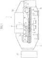
- In
Fig. 1 , shown is the turret punch press machine 1 for working such as punching on a plate-like work W. The punch press machine 1 includes aframe 3 as generally known. Theframe 3 is constructed integrally by an upper frame 3U and alower frame 3L. On the upper frame 3U, an upper turret (upper die holder) 5U is provided horizontally-rotatably. On thelower frame 3L, a lower turret (lower die holder) 51 is provided horizontally-rotatably. - On the
upper turret 5U, pluralpunch attachment holes 5H (seeFig. 2 ) are provided, and punches P are replaceably installed to thepunch attachment holes 5H. On thelower turret 5L, plural die attachment holes (not shown) corresponding to theupper turret 5U are provided, and replaceable dies D corresponding to the punches P are provided in the die attachment holes. In addition, on the upper turret 3U, astriker 7 is provided that strikes a punch head of a punch P set at a work position by rotations of the upper andlower turrets - The
striker 7 is moved vertically by aram driver 9. Theram driver 9 is, for example, a crank mechanism, a link mechanism or a ball screw mechanism that is rotated by a fluid pressure cylinder or a servomotor. A vertical position of thestriker 7 to an original position (reference position: a top dead center, a bottom dead center or the like) is constantly detected by a vertical position detector 93 (seeFig. 3 ) such as a rotary encoder. - In addition, the punch press machine 1 includes a moving and
positioning unit 11 that moves a work W in X- and Y-axis directions relatively to the punch P and the die D set at the work position (position below the striker 7) to set its position, and a work table 13 that movably supports the work W. The moving andpositioning unit 11 includes acarriage base 17 that can move in the Y-axis direction (horizontal direction inFig. 1 ) alongguide rails 15 provided on thelower frame 5L. - The
carriage base 17 is moved in the Y-axis direction by rotation of a Y-axis servomotor (not shown) and then its position is set, and extended in the X-axis direction (vertical direction inFig. 1 ) perpendicularly intersecting with the Y-axis direction. Thecarriage base 17 includes acarriage 19 that is moved in the X-axis direction by rotation of an X-axis servomotor (not shown) and then its position is set. Thecarriage 19 includesplural work clamps 21 for clamping the work W. Each position of thework clamps 21 can be adjusted in the X-axis direction. - Therefore, the
carriage base 17 is moved in the Y-axis direction and then its position is set and thecarriage 19 is moved in the X-axis direction and then its position is set, so that the work W clamped by thework clamps 21 is moved in the X- and Y-axis directions and then its position is set to set a to-be-worked portion on the work W at the work position (position of the punch P and the die D). - The punch press machine 1 includes a
controller 23 such as a CNC controller. Thecontroller 23 mainly executes a rotation control of the upper andlower turrets positioning unit 11, and a strike control of thestriker 7. - Note that, since the punch press machine 1 with the above explained configuration is well known, its further detailed explanations are skipped.
- A
marking tool 25 in the present embodiment is used by being attached to thepunch attachment hole 5H on theupper turret 5U as a substitute for one punch P attached on the upper turret (upper holder) 5U, as shown inFig. 2 . Themarking tool 25 includes acylindrical tool body 27 similarly to a conventional punch P. Thetool body 27 is detachable to thepunch attachment hole 5H, and supported in a state where it is plunged into thepunch attachment hole 5H. A cylindrical upper body 31 is coupled with an upper portion of thetool body 27 by afastener 29 such as a cap nut. A fluid pressure motor (rotary drive unit) 33 such as an air motor is vertically movably housed in the upper body 31. - A
head member 35 is vertically movably supported at an upper portion of the upper body 31 in order to support thefluid pressure motor 33 vertically movably in the upper body 31. Namely, thehead member 35 is supported while being biased upward by a coil spring (elastic member) 37 attached between the upper body 31 and thehead member 35. An upward movement of thehead body 35 is restricted byplural stopper bolts 39 whose lower ends are screw-mounted into the upper body 31. Thefluid pressure motor 33 and thehead member 35 are jointed to each other at a screw-joint portion 41. - In order to supply working fluid, the
head member 35 is provided with aconnection hole 35H connected to asupply hole 7H formed on thestriker 7. Theconnection hole 35H is connected to the fluid pressuremotor 33. Thesupply hole 7H supplies oil mists to the punch P. On aconnection path 45 that connects thesupply hole 7H to anair source 43, an open-close valve 47 such as a solenoid valve and anejector 49 are provided sequentially from theair source 43. Aconnection path 53 connected to anoil tank 51 is connected to theejector 49. An open-close valve 55 is provided on theconnection path 53. - When the open-
close valve 47 is opened in a state where thestriker 7 is being contacted with thehead member 35, air of theair source 43 is supplied to thefluid pressure motor 33 to drive thefluid pressure motor 33. In addition, when the open-close valve 47 and the open-close valve 55 are opened, oil in theoil tank 51 is suctioned by theejector 49 and then supplied to theconnection path 45 as oil mists. Therefore, air or oil mists can be selectively supplied from thesupply hole 7H, so that unnecessary oil consumption can be restricted. - In a
cylindrical bearing holder 59 within thetool body 27, ahollow rotary shaft 63 is provided rotatably viaplural bearings 61. Rotation of thefluid pressure motor 33 is transmitted to a marking pin (rotating tool) 57 of the markingtool 25 via thehollow rotary shaft 63. An upper portion of thehollow rotary shaft 63 is coupled with arotary shaft 67 of thefluid pressure motor 33 by acoupling pin 65, so that thehollow rotary shaft 63 rotates integrally with therotary shaft 67. Thecoupling pin 65 perpendicularly intersects with a shaft center of thehollow rotary shaft 63, and its both ends are fixed to thehollow rotary shaft 63. A middle of thecoupling pin 65 is coupled with a slit 67S axially formed at an end of therotary shaft 67. - A vertically
movable chuck 69 is provided at a lower portion of thehollow rotary shaft 63 while being biased downward. The markingpin 57 is detachably attached to thechuck 69. Thechuck 69 in the present embodiment is a collet chuck. A shank 71S that is an upper portion of a chuckmain body 71 of thechuck 69 is plunged into thehollow rotary shaft 63 vertically movably but unrotatably. Aring spacer 73 that has a slightly larger diameter than a diameter of the shank 71S is attached onto an upper surface of the shank 71S by abolt 75. - A coil spring (elastic member) 79 is provided, while being compressed, between a
spring seat 77 contacted with a lower end surface of therotary shaft 67 and a head of thebolt 75. The shank 71S is meshed with thehollow rotary shaft 63 by splines or keys, and continuously biased downward by thecoil spring 79. Note that, since thespacer 73 is contacted with a stepped portion of thehollow rotary shaft 63, the chuckmain body 71 is prevented from dropping off. - A
large diameter portion 81 in which a tapered hole is formed is provided at a lower portion of the chuckmain body 71. Acollet 83 for holding the markingpin 57 is housed in the tapered hole. A nut 85 is screwed with an outer circumferential surface of thelarge diameter portion 81, and, when the nut 85 is fastened, thecollet 83 fixes the markingpin 57. - According to the above-explained configuration, rotation of the
rotary shaft 67 of thefluid pressure motor 33 is transmitted to the markingpin 57. A spherical portion 57S is formed at a distal end (lower end) of the markingpin 57, and the spherical portion 57S engraves markings on a surface of the work W. Hard fine particles such as diamonds are provided on the spherical portion 57S. - A marking is engraved by spinning the marking
pin 57 while contacting the spherical portion 57S with the surface of the work W and moving the spherical portion 57S relatively to the work W to draw a line on the surface of the work W. In a case where the marking is processed while the spherical portion 57S is contacted with the surface of the work W, an unfavorable circular marking having a diameter larger than a width of the line may be left at a start position (marking start position) and an end position (marking end position) of the marking. - In addition, in a case where a marking is processed only to a protection film on a surface of a work W, an unfavorable marking may be left on the surface of the work W after peeling away the protection film. Improvement of marking quality that can prevent these unfavorable markings is desired.
- Therefore, in the present embodiment, improvement of marking quality is adopted. Namely, the
controller 23 includes aprogram interpreter 89 and acomparator 95, as shown inFig. 3 . Theprogram interpreter 89 interprets awork program 87 input thereto. Thecomparator 95 compares, in a case where a marking process is found in the work program interpreted by theprogram interpreter 89, a preset value preset in amemory 91 with a detected value of thevertical position detector 93 that detects the vertical position of thestriker 7. In addition, thecontroller 23 includes an operationalcommand output unit 97 that outputs an operational command concurrently to the moving andpositioning unit 11 and therotational drive unit 33 when the preset value is equal to the detected value mentioned above. - The preset value preset in the
memory 91 is a value corresponding to a stroke amount from a position at which thestriker 7 starts moving downward from its top dead center (or its reference position when lifted up) to become contacted with thehead member 35 to a position at which the spherical portion 57S of the markingpin 57 becomes contacted with the upper surface (the surface) of the work W while the marking tool is moved downward against a lifter spring 99 (seeFig. 2 ). - Note that known is a distance S1 between a bottom surface of the
striker 7 and an upper surface of thehead member 35 at a time when the striker positions at its reference position. In addition, also known is a distance S2 between thespherical portion 57 and the upper surface of the work W in a state where the markingtool 25 is lifted up by thelifter spring 99. Therefore, the preset value preset in thememory 91 is (S1 + S2 + α). Here, α is a correction value corresponding to thickness tolerance when the work W is made, and can take zero. The value α is determined by previously measuring a thickness of the work W. - Processes of marking will be explained with reference to
Fig. 4 . First, the work program is interpreted by the program interpreter 89 (step S1). Then, if a marking process is found in the work program (YES in step S2), a to-be-worked portion of the work W is positioned in association with the markingtool 25 previously positioned at the work position (step S3) and thestriker 7 is moved downward by the ram driver 9 (step S4) . - The position of the
striker 7 moved downward from its reference position is detected by thevertical position detector 93, and thecomparator 95 compares the detected value by thevertical position detector 93 with the preset value stored in thememory 91. If the detected value is equal to the preset value (YES in step S5), it is judged that the spherical portion 57S of the markingpin 57 is contacted with the upper surface of the work W and a downward motion of thestriker 7 is stopped (step S6). - Note that, when the spherical portion 57S is contacted with the upper surface of the work W, the
coil spring 79 is slightly compressed so as to absorb an error, a minor error in the preset value can be compensated. Namely, is can be done to preset the preset value slightly large, so that the spherical portion 57S can be contacted with the upper surface of the work W unfailingly. - When the
striker 7 and the markingtool 25 are moved downward to the preset position previously set, the operational command is output from the operationalcommand output unit 97 to the moving andpositioning unit 11 and therotational drive unit 33. As a result, spinning of the markingpin 57 is started and traveling thereof for marking on the work W is concurrently started, so that marking is processed (step S7). - Namely, under a condition where the spherical portion 57S of the marking
pin 57 is contacted with the upper surface of the work and the markingpin 57 is kept to be slightly biased downward by thecoil spring 79, relative movement of the work W in the X-axis and/or Y-axis direction and spinning of the markingpin 57 are concurrently started. Therefore, the marking start position (start position) is not processed more than a portion of drawing a line, so that no unfavorable circular marking having a diameter larger than a width of the line is left at the marking start position. - Note that a time needed for the marking
pin 57 to reach a desired rotational speed is almost equal to a time needed for the work W to reach a desired moving speed. Therefore, a moving speed of the work W accelerates to the desired moving speed while a rotational speed of the markingpin 57 accelerates to the desired rotational speed. A processing amount per a unit length of a marked line by the markingpin 57 during these accelerations is almost equal to a processing amount per a unit length of a marked line while a moving speed of the work W is the desired moving speed and the a rotational speed of the markingpin 57 is the desired rotational speed. Therefore, a width of the marked line during the accelerations is almost equal to a line width while a moving speed of the work W is the desired moving speed and the rotational speed of the markingpin 57 is the desired rotational speed. - Here, if a contact time of the marking
pin 57 with the work W in one segment on the marked line becomes longer than that in other segments, the processing amount in the one segment becomes larger than that in the other segments and thereby its line width becomes bold, because the markingpin 57 is biased downward by thecoil spring 79. Therefore, in a case where the moving speed of the work W relative to the markingpin 57 is constant, it is preferable that the contact time of the work W with the markingpin 57 per a unit length of a marked line is constant. Namely, it is preferable that a processing amount per a unit length of a marked line is kept constant over an entire length of the marked line. - As explained above, since moving of the work W and spinning of the marking
pin 57 are started concurrently, the processing amount by the markingpin 57 at the marking start position is almost equal to a processing amount at a given position on the marked line, and the processing amount per a unit length of the marked line is also constant, so that a width of the marked line becomes constant over its entire length. - After step S7, the marking process is finished (step S8). If the marking end position is positioned outside the work W or outside a product, it doesn't become a problem to continue spinning of the marking
pin 57 at the marking end position in step S8. However, if the marking end position is positioned upon a product, the relative movement of the work W and the spinning of the markingpin 57 are stopped concurrently. Alternatively, in step S8, the markingpin 57 is separated from the work W at the same time when the relative movement of the work W is stopped. According to these, no unfavorable circular marking having a diameter larger than a width of the line is left at the marking end position. - As explained above, under a condition where the marking
pin 57 is contacted with the work W, the movement of the work W and the spinning of the markingpin 57 is concurrently started, and the movement of the work W and the spinning of the markingpin 57 is concurrently ended (alternatively, the markingpin 57 is separated from the work W), so that no unfavorable circular marking is left at the marking start position and the marking end position on the work W having a thin protection film on its surface. Namely, even if the protection film is extremely thin, marking can be processed without tearing the protection film (without penetrating the protection film). Therefore, no unfavorable circular marking is left on a surface of a product. - As explained above, since the contact time of the work W with the marking
pin 57 per a unit length of a marked line is constant, uniform workings can be done over the entire length of the marking line. Namely, no fluctuation of the processing amount on the marked line is made, so that the line width becomes constant over the entire length and thereby its appearance improved. - Note that, although the
rotary drive unit 33 in the present embodiment is a fluid pressure motor, it may be a servomotor. In addition, it may be done that the relative movement of the work W in the X-axis and/or Y-axis direction is started at the same time when the markingtool 25 being spun at a desired rotational speed is contacted with the work W.
Claims (6)
- A method for marking on a surface of a plate-like work (W), the method comprising:keeping a state where an end of a rotating tool (57) for marking is contacted with a surface of the work (W);characterized bystarting a relative movement of the work in an X-axis direction and/or in a Y-axis direction relative to the rotating tool (57), and concurrently starting a rotation of the rotating tool (57).
- The method for marking according to claim 1, further comprising:stopping the rotation of the rotating tool (57) or separating the rotating tool (57) from the surface of the work (W) at a same time of stopping the relative movement of the work (W).
- A method for marking on a surface of a plate-like work (W), the method comprising:keeping a rotational speed of a rotating tool (57) for marking to a desired rotational speed;and starting a relative movement of the work (W) in an X-axis direction and/or in a Y-axis direction relative to the rotating tool (57) at a same time of contacting a spherical portion (57S) of the rotating tool with the surface of the work (W).
- The method for marking according to any one of claims 1 to 3, wherein the work (W) has a protection film capable of being peeled away on a surface thereof.
- A punch press machine for marking on a surface of a plate-like work (W) comprising:a marking tool (25), andan upper die holder (5U) to which the marking tool (25) or a punch (P) is replaceably installed; a work (W) table for supporting the work (W) worked by the marking tool (25) or the punch (P); a vertically movable striker (7) that can press down a head member (35) of the marking tool (25) or the punch (7) and a vertical position detector (93) for detecting a vertical position of the striker (7);characterized in that
the punch press machine further comprising a command output unit (97) that is configured to output, under a condition where the marking tool (25) is contacted with the surface of the work (W), an operational command concurrently to a moving and positioning unit for moving the work (W) in an X-axis direction and/or a Y-axis direction relatively to the marking tool (25) or the punch (P) and to the marking tool (25) in order to start a relative movement of the work (W) in an X-axis direction and/or in a Y-axis direction relative to the marking tool (25), and concurrently starting a rotation of a rotating tool (57) of the marking tool (25). - The punch press machine of claim 5, wherein the marking tool (25) further comprises:a cylindrical tool body (27) detachably and vertically movably attachable to an upper die holder (5U) of a punch press machine; a rotational drive unit (33) provided above the tool body (27); a hollow rotary shaft (63) rotated by the rotational drive unit (33); a chuck (69) vertically movably provided at a lower portion of the hollow rotary shaft (63) and biased downward; and the rotating tool (57) that includes a spherical portion (57S) for marking at a lower end thereof, wherein the rotating tool (57) is detachably held by the chuck.
Applications Claiming Priority (2)
| Application Number | Priority Date | Filing Date | Title |
|---|---|---|---|
| JP2010018677AJP5603608B2 (en) | 2010-01-29 | 2010-01-29 | Marking method, marking tool, punch press |
| PCT/JP2011/051720WO2011093435A1 (en) | 2010-01-29 | 2011-01-28 | Marking method, marking tool, and punch press machine |
Publications (3)
| Publication Number | Publication Date |
|---|---|
| EP2529853A1 EP2529853A1 (en) | 2012-12-05 |
| EP2529853A4 EP2529853A4 (en) | 2015-06-10 |
| EP2529853B1true EP2529853B1 (en) | 2019-01-23 |
Family
ID=44319416
Family Applications (1)
| Application Number | Title | Priority Date | Filing Date |
|---|---|---|---|
| EP11737145.0ANot-in-forceEP2529853B1 (en) | 2010-01-29 | 2011-01-28 | Marking method and punch press machine with a marking tool |
Country Status (5)
| Country | Link |
|---|---|
| US (1) | US10232423B2 (en) |
| EP (1) | EP2529853B1 (en) |
| JP (1) | JP5603608B2 (en) |
| CN (1) | CN102725080B (en) |
| WO (1) | WO2011093435A1 (en) |
Families Citing this family (4)
| Publication number | Priority date | Publication date | Assignee | Title |
|---|---|---|---|---|
| JP5913989B2 (en) | 2012-01-10 | 2016-05-11 | 株式会社アマダホールディングス | Press machine |
| CN105537445B (en)* | 2016-02-29 | 2017-12-12 | 长江大学 | A kind of automatically continuously punching press whole-course automation equipment |
| CN108858114B (en)* | 2018-06-30 | 2021-04-30 | 佛山科枫文化传播有限公司 | Board processing marking machine for carpenter |
| CN111038169A (en)* | 2020-01-08 | 2020-04-21 | 茹卫红 | Square crystal ball base strikes angle device |
Family Cites Families (27)
| Publication number | Priority date | Publication date | Assignee | Title |
|---|---|---|---|---|
| AU555957B2 (en)* | 1981-10-20 | 1986-10-16 | Amada Company Limited | Turret punch press |
| JPS6138877A (en)* | 1984-07-30 | 1986-02-24 | 吉野石膏株式会社 | Marking method and device thereof |
| JPS61197174A (en)* | 1984-08-31 | 1986-09-01 | 三菱重工業株式会社 | Marking head |
| US5044239A (en)* | 1988-02-25 | 1991-09-03 | Amada Engineering & Service Co., Inc. | Punch for punch press |
| CN2036890U (en)* | 1988-10-22 | 1989-05-03 | 陈希平 | Semiautomatic drawing punch |
| US5201589A (en) | 1989-05-22 | 1993-04-13 | Murata Wiedemann | Marking tool holder for a punch press |
| US5259100A (en)* | 1992-05-27 | 1993-11-09 | Amada Engineering & Service Co., Inc. | Milling tool for turret punch press |
| US5394335A (en)* | 1993-03-31 | 1995-02-28 | Amada Engineering & Service Co., Inc. | Retrofit auto-indexing system |
| US5432704A (en)* | 1993-11-23 | 1995-07-11 | Clemson University | Adaptive lamina generation for shape dependent process control and/or object decomposition |
| CA2285364C (en)* | 1998-01-29 | 2004-10-05 | Amino Corporation | Apparatus for dieless forming plate materials |
| US20010042453A1 (en)* | 1999-10-14 | 2001-11-22 | Albrecht Schneider | Method and apparatus for marking workpieces |
| JP4398044B2 (en)* | 2000-02-03 | 2010-01-13 | 東芝機械株式会社 | Numerical control device and control method for machine tool |
| JP2002178044A (en)* | 2000-12-13 | 2002-06-25 | Hitachi Telecom Technol Ltd | Turret punch press mold equipment |
| KR100413206B1 (en)* | 2001-03-08 | 2003-12-31 | 김용기 | Tool positon determination system for a machine tool with spindle |
| JP2003094197A (en)* | 2001-09-21 | 2003-04-02 | Amada Eng Center Co Ltd | Press machine and press working method using it |
| JP3777130B2 (en)* | 2002-02-19 | 2006-05-24 | 本田技研工業株式会社 | Sequential molding equipment |
| CA2483666C (en)* | 2002-04-30 | 2009-03-17 | Daiwa Can Company | Opening curled portion of metal can and forming method thereof |
| JP2004050346A (en)* | 2002-07-19 | 2004-02-19 | Zeniya Aluminum Engineering Ltd | Scribing device equipped with rotary scriber |
| AU2003275710A1 (en)* | 2002-10-28 | 2004-05-13 | Amada Company, Limited | Tapping method and device, and punch press |
| CN100396448C (en)* | 2003-01-15 | 2008-06-25 | Thk株式会社 | marking device |
| JP2005034950A (en) | 2003-07-15 | 2005-02-10 | Amada Co Ltd | Mechanism and method for marking |
| DE10337489B4 (en)* | 2003-08-14 | 2007-04-19 | P & L Gmbh & Co. Kg | Method for automatic tool wear correction |
| JP4568577B2 (en)* | 2004-10-28 | 2010-10-27 | 株式会社アマダ | Rotary cutting tool |
| JP2007007776A (en)* | 2005-06-30 | 2007-01-18 | Alps Engineering Co Ltd | Alignment mark forming method |
| GB0612452D0 (en)* | 2006-06-22 | 2006-08-02 | Univ Aston | Improvements in or relating to drilling apparatus and methods |
| JP2008264931A (en)* | 2007-04-20 | 2008-11-06 | Captain Industries Inc | Scratch tool for engraving |
| US8858853B2 (en)* | 2008-04-04 | 2014-10-14 | The Boeing Company | Formed sheet metal composite tooling |
- 2010
- 2010-01-29JPJP2010018677Apatent/JP5603608B2/ennot_activeExpired - Fee Related
- 2011
- 2011-01-28WOPCT/JP2011/051720patent/WO2011093435A1/enactiveApplication Filing
- 2011-01-28USUS13/575,486patent/US10232423B2/ennot_activeExpired - Fee Related
- 2011-01-28EPEP11737145.0Apatent/EP2529853B1/ennot_activeNot-in-force
- 2011-01-28CNCN201180007139.3Apatent/CN102725080B/ennot_activeExpired - Fee Related
Non-Patent Citations (1)
| Title |
|---|
| None* |
Also Published As
| Publication number | Publication date |
|---|---|
| US10232423B2 (en) | 2019-03-19 |
| US20120297848A1 (en) | 2012-11-29 |
| CN102725080B (en) | 2016-01-20 |
| WO2011093435A1 (en) | 2011-08-04 |
| JP2011156547A (en) | 2011-08-18 |
| JP5603608B2 (en) | 2014-10-08 |
| EP2529853A1 (en) | 2012-12-05 |
| EP2529853A4 (en) | 2015-06-10 |
| CN102725080A (en) | 2012-10-10 |
Similar Documents
| Publication | Publication Date | Title |
|---|---|---|
| US8443643B2 (en) | Burr removing method and device | |
| US8777526B2 (en) | Deep hole processing device | |
| EP2529853B1 (en) | Marking method and punch press machine with a marking tool | |
| CN107891087B (en) | Punching and cutting integrated processing equipment | |
| DE102014017285B4 (en) | An article fixing device for fixing an object to a receiving part, a machine tool, a robot, and a method of fixing an article to a receiving part | |
| KR20130048697A (en) | Clamp device of a drill and air drive drill | |
| JP6688829B2 (en) | Machine Tools | |
| KR101086610B1 (en) | Spindle Module for CNC Engraver with Automatic Tool Changer | |
| CN204748025U (en) | Dull and stereotyped high -speed drill compounding machine of numerical control hydraulic pressure | |
| CN207709640U (en) | A kind of special hole punched device of cone barrel workpiece | |
| CN206169636U (en) | Cutter side formula lathe that processing is nimble | |
| JP3130748B2 (en) | Engraving tool and device therefor | |
| CN211333524U (en) | Combined tool bit module of full-automatic strip-to-lattice high-speed single-layer cutting machine | |
| JP2000000735A (en) | Pressure foot for printed board finishing machine | |
| CN207709633U (en) | A kind of blanking integrated processing device | |
| JP2000288835A (en) | Tapping device for plate material working machine | |
| JP2000343301A (en) | Bar-shaped workpiece support device and method for machine tool for turning | |
| CN206185468U (en) | Lathe of formula of putting under cutter | |
| JPH11290967A (en) | Tapping device for punch press | |
| JP2005279858A (en) | Work rotation device | |
| JP4946967B2 (en) | Chamfering tool | |
| JPH0133288B2 (en) | ||
| JP5198885B2 (en) | Machine tool and workpiece machining method | |
| JPH07106489B2 (en) | Hat body hole processing device | |
| JP2011104664A (en) | Machining device and method for pyramid recessed part |
Legal Events
| Date | Code | Title | Description |
|---|---|---|---|
| PUAI | Public reference made under article 153(3) epc to a published international application that has entered the european phase | Free format text:ORIGINAL CODE: 0009012 | |
| 17P | Request for examination filed | Effective date:20120828 | |
| AK | Designated contracting states | Kind code of ref document:A1 Designated state(s):AL AT BE BG CH CY CZ DE DK EE ES FI FR GB GR HR HU IE IS IT LI LT LU LV MC MK MT NL NO PL PT RO RS SE SI SK SM TR | |
| DAX | Request for extension of the european patent (deleted) | ||
| RA4 | Supplementary search report drawn up and despatched (corrected) | Effective date:20150512 | |
| RIC1 | Information provided on ipc code assigned before grant | Ipc:B25H 7/04 20060101AFI20150506BHEP Ipc:B44B 5/00 20060101ALI20150506BHEP | |
| RAP1 | Party data changed (applicant data changed or rights of an application transferred) | Owner name:AMADA COMPANY, LIMITED | |
| STAA | Information on the status of an ep patent application or granted ep patent | Free format text:STATUS: EXAMINATION IS IN PROGRESS | |
| 17Q | First examination report despatched | Effective date:20170117 | |
| GRAP | Despatch of communication of intention to grant a patent | Free format text:ORIGINAL CODE: EPIDOSNIGR1 | |
| STAA | Information on the status of an ep patent application or granted ep patent | Free format text:STATUS: GRANT OF PATENT IS INTENDED | |
| INTG | Intention to grant announced | Effective date:20180831 | |
| GRAS | Grant fee paid | Free format text:ORIGINAL CODE: EPIDOSNIGR3 | |
| GRAA | (expected) grant | Free format text:ORIGINAL CODE: 0009210 | |
| STAA | Information on the status of an ep patent application or granted ep patent | Free format text:STATUS: THE PATENT HAS BEEN GRANTED | |
| AK | Designated contracting states | Kind code of ref document:B1 Designated state(s):AL AT BE BG CH CY CZ DE DK EE ES FI FR GB GR HR HU IE IS IT LI LT LU LV MC MK MT NL NO PL PT RO RS SE SI SK SM TR | |
| REG | Reference to a national code | Ref country code:GB Ref legal event code:FG4D | |
| REG | Reference to a national code | Ref country code:CH Ref legal event code:EP | |
| REG | Reference to a national code | Ref country code:AT Ref legal event code:REF Ref document number:1091086 Country of ref document:AT Kind code of ref document:T Effective date:20190215 | |
| REG | Reference to a national code | Ref country code:IE Ref legal event code:FG4D | |
| REG | Reference to a national code | Ref country code:DE Ref legal event code:R096 Ref document number:602011055906 Country of ref document:DE | |
| REG | Reference to a national code | Ref country code:NL Ref legal event code:MP Effective date:20190123 | |
| PG25 | Lapsed in a contracting state [announced via postgrant information from national office to epo] | Ref country code:NL Free format text:LAPSE BECAUSE OF FAILURE TO SUBMIT A TRANSLATION OF THE DESCRIPTION OR TO PAY THE FEE WITHIN THE PRESCRIBED TIME-LIMIT Effective date:20190123 | |
| PG25 | Lapsed in a contracting state [announced via postgrant information from national office to epo] | Ref country code:FI Free format text:LAPSE BECAUSE OF FAILURE TO SUBMIT A TRANSLATION OF THE DESCRIPTION OR TO PAY THE FEE WITHIN THE PRESCRIBED TIME-LIMIT Effective date:20190123 Ref country code:SE Free format text:LAPSE BECAUSE OF FAILURE TO SUBMIT A TRANSLATION OF THE DESCRIPTION OR TO PAY THE FEE WITHIN THE PRESCRIBED TIME-LIMIT Effective date:20190123 Ref country code:NO Free format text:LAPSE BECAUSE OF FAILURE TO SUBMIT A TRANSLATION OF THE DESCRIPTION OR TO PAY THE FEE WITHIN THE PRESCRIBED TIME-LIMIT Effective date:20190423 Ref country code:PL Free format text:LAPSE BECAUSE OF FAILURE TO SUBMIT A TRANSLATION OF THE DESCRIPTION OR TO PAY THE FEE WITHIN THE PRESCRIBED TIME-LIMIT Effective date:20190123 Ref country code:ES Free format text:LAPSE BECAUSE OF FAILURE TO SUBMIT A TRANSLATION OF THE DESCRIPTION OR TO PAY THE FEE WITHIN THE PRESCRIBED TIME-LIMIT Effective date:20190123 Ref country code:LT Free format text:LAPSE BECAUSE OF FAILURE TO SUBMIT A TRANSLATION OF THE DESCRIPTION OR TO PAY THE FEE WITHIN THE PRESCRIBED TIME-LIMIT Effective date:20190123 Ref country code:PT Free format text:LAPSE BECAUSE OF FAILURE TO SUBMIT A TRANSLATION OF THE DESCRIPTION OR TO PAY THE FEE WITHIN THE PRESCRIBED TIME-LIMIT Effective date:20190523 | |
| REG | Reference to a national code | Ref country code:DE Ref legal event code:R409 Ref document number:602011055906 Country of ref document:DE Ref country code:DE Ref legal event code:R119 Ref document number:602011055906 Country of ref document:DE | |
| REG | Reference to a national code | Ref country code:AT Ref legal event code:MK05 Ref document number:1091086 Country of ref document:AT Kind code of ref document:T Effective date:20190123 | |
| PG25 | Lapsed in a contracting state [announced via postgrant information from national office to epo] | Ref country code:HR Free format text:LAPSE BECAUSE OF FAILURE TO SUBMIT A TRANSLATION OF THE DESCRIPTION OR TO PAY THE FEE WITHIN THE PRESCRIBED TIME-LIMIT Effective date:20190123 Ref country code:LV Free format text:LAPSE BECAUSE OF FAILURE TO SUBMIT A TRANSLATION OF THE DESCRIPTION OR TO PAY THE FEE WITHIN THE PRESCRIBED TIME-LIMIT Effective date:20190123 Ref country code:BG Free format text:LAPSE BECAUSE OF FAILURE TO SUBMIT A TRANSLATION OF THE DESCRIPTION OR TO PAY THE FEE WITHIN THE PRESCRIBED TIME-LIMIT Effective date:20190423 Ref country code:RS Free format text:LAPSE BECAUSE OF FAILURE TO SUBMIT A TRANSLATION OF THE DESCRIPTION OR TO PAY THE FEE WITHIN THE PRESCRIBED TIME-LIMIT Effective date:20190123 Ref country code:IS Free format text:LAPSE BECAUSE OF FAILURE TO SUBMIT A TRANSLATION OF THE DESCRIPTION OR TO PAY THE FEE WITHIN THE PRESCRIBED TIME-LIMIT Effective date:20190523 Ref country code:GR Free format text:LAPSE BECAUSE OF FAILURE TO SUBMIT A TRANSLATION OF THE DESCRIPTION OR TO PAY THE FEE WITHIN THE PRESCRIBED TIME-LIMIT Effective date:20190424 | |
| REG | Reference to a national code | Ref country code:CH Ref legal event code:PL | |
| PG25 | Lapsed in a contracting state [announced via postgrant information from national office to epo] | Ref country code:LU Free format text:LAPSE BECAUSE OF NON-PAYMENT OF DUE FEES Effective date:20190128 | |
| REG | Reference to a national code | Ref country code:BE Ref legal event code:MM Effective date:20190131 | |
| REG | Reference to a national code | Ref country code:DE Ref legal event code:R097 Ref document number:602011055906 Country of ref document:DE | |
| REG | Reference to a national code | Ref country code:IE Ref legal event code:MM4A | |
| PG25 | Lapsed in a contracting state [announced via postgrant information from national office to epo] | Ref country code:CZ Free format text:LAPSE BECAUSE OF FAILURE TO SUBMIT A TRANSLATION OF THE DESCRIPTION OR TO PAY THE FEE WITHIN THE PRESCRIBED TIME-LIMIT Effective date:20190123 Ref country code:EE Free format text:LAPSE BECAUSE OF FAILURE TO SUBMIT A TRANSLATION OF THE DESCRIPTION OR TO PAY THE FEE WITHIN THE PRESCRIBED TIME-LIMIT Effective date:20190123 Ref country code:DK Free format text:LAPSE BECAUSE OF FAILURE TO SUBMIT A TRANSLATION OF THE DESCRIPTION OR TO PAY THE FEE WITHIN THE PRESCRIBED TIME-LIMIT Effective date:20190123 Ref country code:MC Free format text:LAPSE BECAUSE OF FAILURE TO SUBMIT A TRANSLATION OF THE DESCRIPTION OR TO PAY THE FEE WITHIN THE PRESCRIBED TIME-LIMIT Effective date:20190123 Ref country code:AL Free format text:LAPSE BECAUSE OF FAILURE TO SUBMIT A TRANSLATION OF THE DESCRIPTION OR TO PAY THE FEE WITHIN THE PRESCRIBED TIME-LIMIT Effective date:20190123 Ref country code:IT Free format text:LAPSE BECAUSE OF FAILURE TO SUBMIT A TRANSLATION OF THE DESCRIPTION OR TO PAY THE FEE WITHIN THE PRESCRIBED TIME-LIMIT Effective date:20190123 Ref country code:RO Free format text:LAPSE BECAUSE OF FAILURE TO SUBMIT A TRANSLATION OF THE DESCRIPTION OR TO PAY THE FEE WITHIN THE PRESCRIBED TIME-LIMIT Effective date:20190123 Ref country code:SK Free format text:LAPSE BECAUSE OF FAILURE TO SUBMIT A TRANSLATION OF THE DESCRIPTION OR TO PAY THE FEE WITHIN THE PRESCRIBED TIME-LIMIT Effective date:20190123 Ref country code:DE Free format text:LAPSE BECAUSE OF NON-PAYMENT OF DUE FEES Effective date:20190801 | |
| PG25 | Lapsed in a contracting state [announced via postgrant information from national office to epo] | Ref country code:SM Free format text:LAPSE BECAUSE OF FAILURE TO SUBMIT A TRANSLATION OF THE DESCRIPTION OR TO PAY THE FEE WITHIN THE PRESCRIBED TIME-LIMIT Effective date:20190123 Ref country code:BE Free format text:LAPSE BECAUSE OF NON-PAYMENT OF DUE FEES Effective date:20190131 | |
| PLBE | No opposition filed within time limit | Free format text:ORIGINAL CODE: 0009261 | |
| STAA | Information on the status of an ep patent application or granted ep patent | Free format text:STATUS: NO OPPOSITION FILED WITHIN TIME LIMIT | |
| GBPC | Gb: european patent ceased through non-payment of renewal fee | Effective date:20190423 | |
| PG25 | Lapsed in a contracting state [announced via postgrant information from national office to epo] | Ref country code:AT Free format text:LAPSE BECAUSE OF FAILURE TO SUBMIT A TRANSLATION OF THE DESCRIPTION OR TO PAY THE FEE WITHIN THE PRESCRIBED TIME-LIMIT Effective date:20190123 Ref country code:LI Free format text:LAPSE BECAUSE OF NON-PAYMENT OF DUE FEES Effective date:20190131 Ref country code:CH Free format text:LAPSE BECAUSE OF NON-PAYMENT OF DUE FEES Effective date:20190131 | |
| 26N | No opposition filed | Effective date:20191024 | |
| PG25 | Lapsed in a contracting state [announced via postgrant information from national office to epo] | Ref country code:DE Free format text:LAPSE BECAUSE OF NON-PAYMENT OF DUE FEES Effective date:20190801 Ref country code:GB Free format text:LAPSE BECAUSE OF NON-PAYMENT OF DUE FEES Effective date:20190423 Ref country code:IE Free format text:LAPSE BECAUSE OF NON-PAYMENT OF DUE FEES Effective date:20190128 | |
| PGRI | Patent reinstated in contracting state [announced from national office to epo] | Ref country code:DE Effective date:20191016 | |
| PG25 | Lapsed in a contracting state [announced via postgrant information from national office to epo] | Ref country code:FR Free format text:LAPSE BECAUSE OF NON-PAYMENT OF DUE FEES Effective date:20190323 Ref country code:SI Free format text:LAPSE BECAUSE OF FAILURE TO SUBMIT A TRANSLATION OF THE DESCRIPTION OR TO PAY THE FEE WITHIN THE PRESCRIBED TIME-LIMIT Effective date:20190123 | |
| PG25 | Lapsed in a contracting state [announced via postgrant information from national office to epo] | Ref country code:TR Free format text:LAPSE BECAUSE OF FAILURE TO SUBMIT A TRANSLATION OF THE DESCRIPTION OR TO PAY THE FEE WITHIN THE PRESCRIBED TIME-LIMIT Effective date:20190123 | |
| PGFP | Annual fee paid to national office [announced via postgrant information from national office to epo] | Ref country code:DE Payment date:20200127 Year of fee payment:10 | |
| PG25 | Lapsed in a contracting state [announced via postgrant information from national office to epo] | Ref country code:MT Free format text:LAPSE BECAUSE OF NON-PAYMENT OF DUE FEES Effective date:20190128 | |
| PG25 | Lapsed in a contracting state [announced via postgrant information from national office to epo] | Ref country code:CY Free format text:LAPSE BECAUSE OF FAILURE TO SUBMIT A TRANSLATION OF THE DESCRIPTION OR TO PAY THE FEE WITHIN THE PRESCRIBED TIME-LIMIT Effective date:20190123 | |
| PG25 | Lapsed in a contracting state [announced via postgrant information from national office to epo] | Ref country code:HU Free format text:LAPSE BECAUSE OF FAILURE TO SUBMIT A TRANSLATION OF THE DESCRIPTION OR TO PAY THE FEE WITHIN THE PRESCRIBED TIME-LIMIT; INVALID AB INITIO Effective date:20110128 | |
| REG | Reference to a national code | Ref country code:DE Ref legal event code:R119 Ref document number:602011055906 Country of ref document:DE | |
| PG25 | Lapsed in a contracting state [announced via postgrant information from national office to epo] | Ref country code:DE Free format text:LAPSE BECAUSE OF NON-PAYMENT OF DUE FEES Effective date:20210803 | |
| PG25 | Lapsed in a contracting state [announced via postgrant information from national office to epo] | Ref country code:MK Free format text:LAPSE BECAUSE OF FAILURE TO SUBMIT A TRANSLATION OF THE DESCRIPTION OR TO PAY THE FEE WITHIN THE PRESCRIBED TIME-LIMIT Effective date:20190123 |