EP2529782B1 - Hemostatic band - Google Patents
Hemostatic bandDownload PDFInfo
- Publication number
- EP2529782B1 EP2529782B1EP11762719.0AEP11762719AEP2529782B1EP 2529782 B1EP2529782 B1EP 2529782B1EP 11762719 AEP11762719 AEP 11762719AEP 2529782 B1EP2529782 B1EP 2529782B1
- Authority
- EP
- European Patent Office
- Prior art keywords
- sheath
- balloon
- band
- hub
- tube
- Prior art date
- Legal status (The legal status is an assumption and is not a legal conclusion. Google has not performed a legal analysis and makes no representation as to the accuracy of the status listed.)
- Active
Links
Images


Classifications
- A—HUMAN NECESSITIES
- A61—MEDICAL OR VETERINARY SCIENCE; HYGIENE
- A61B—DIAGNOSIS; SURGERY; IDENTIFICATION
- A61B17/00—Surgical instruments, devices or methods
- A61B17/12—Surgical instruments, devices or methods for ligaturing or otherwise compressing tubular parts of the body, e.g. blood vessels or umbilical cord
- A61B17/132—Tourniquets
- A61B17/1322—Tourniquets comprising a flexible encircling member
- A61B17/1325—Tourniquets comprising a flexible encircling member with means for applying local pressure
- A—HUMAN NECESSITIES
- A61—MEDICAL OR VETERINARY SCIENCE; HYGIENE
- A61B—DIAGNOSIS; SURGERY; IDENTIFICATION
- A61B17/00—Surgical instruments, devices or methods
- A61B17/12—Surgical instruments, devices or methods for ligaturing or otherwise compressing tubular parts of the body, e.g. blood vessels or umbilical cord
- A61B17/132—Tourniquets
- A61B17/135—Tourniquets inflatable
- A—HUMAN NECESSITIES
- A61—MEDICAL OR VETERINARY SCIENCE; HYGIENE
- A61M—DEVICES FOR INTRODUCING MEDIA INTO, OR ONTO, THE BODY; DEVICES FOR TRANSDUCING BODY MEDIA OR FOR TAKING MEDIA FROM THE BODY; DEVICES FOR PRODUCING OR ENDING SLEEP OR STUPOR
- A61M25/00—Catheters; Hollow probes
- A61M25/0097—Catheters; Hollow probes characterised by the hub
- A—HUMAN NECESSITIES
- A61—MEDICAL OR VETERINARY SCIENCE; HYGIENE
- A61M—DEVICES FOR INTRODUCING MEDIA INTO, OR ONTO, THE BODY; DEVICES FOR TRANSDUCING BODY MEDIA OR FOR TAKING MEDIA FROM THE BODY; DEVICES FOR PRODUCING OR ENDING SLEEP OR STUPOR
- A61M25/00—Catheters; Hollow probes
- A61M25/01—Introducing, guiding, advancing, emplacing or holding catheters
- A61M25/02—Holding devices, e.g. on the body
- A—HUMAN NECESSITIES
- A61—MEDICAL OR VETERINARY SCIENCE; HYGIENE
- A61M—DEVICES FOR INTRODUCING MEDIA INTO, OR ONTO, THE BODY; DEVICES FOR TRANSDUCING BODY MEDIA OR FOR TAKING MEDIA FROM THE BODY; DEVICES FOR PRODUCING OR ENDING SLEEP OR STUPOR
- A61M29/00—Dilators with or without means for introducing media, e.g. remedies
- A—HUMAN NECESSITIES
- A61—MEDICAL OR VETERINARY SCIENCE; HYGIENE
- A61M—DEVICES FOR INTRODUCING MEDIA INTO, OR ONTO, THE BODY; DEVICES FOR TRANSDUCING BODY MEDIA OR FOR TAKING MEDIA FROM THE BODY; DEVICES FOR PRODUCING OR ENDING SLEEP OR STUPOR
- A61M25/00—Catheters; Hollow probes
- A61M25/01—Introducing, guiding, advancing, emplacing or holding catheters
- A61M25/02—Holding devices, e.g. on the body
- A61M2025/0206—Holding devices, e.g. on the body where the catheter is secured by using devices worn by the patient, e.g. belts or harnesses
- A—HUMAN NECESSITIES
- A61—MEDICAL OR VETERINARY SCIENCE; HYGIENE
- A61M—DEVICES FOR INTRODUCING MEDIA INTO, OR ONTO, THE BODY; DEVICES FOR TRANSDUCING BODY MEDIA OR FOR TAKING MEDIA FROM THE BODY; DEVICES FOR PRODUCING OR ENDING SLEEP OR STUPOR
- A61M25/00—Catheters; Hollow probes
- A61M25/01—Introducing, guiding, advancing, emplacing or holding catheters
- A61M25/02—Holding devices, e.g. on the body
- A61M2025/0213—Holding devices, e.g. on the body where the catheter is attached by means specifically adapted to a part of the human body
- A—HUMAN NECESSITIES
- A61—MEDICAL OR VETERINARY SCIENCE; HYGIENE
- A61M—DEVICES FOR INTRODUCING MEDIA INTO, OR ONTO, THE BODY; DEVICES FOR TRANSDUCING BODY MEDIA OR FOR TAKING MEDIA FROM THE BODY; DEVICES FOR PRODUCING OR ENDING SLEEP OR STUPOR
- A61M25/00—Catheters; Hollow probes
- A61M25/01—Introducing, guiding, advancing, emplacing or holding catheters
- A61M25/02—Holding devices, e.g. on the body
- A61M2025/0253—Holding devices, e.g. on the body where the catheter is attached by straps, bands or the like secured by adhesives
- A61M2025/026—Holding devices, e.g. on the body where the catheter is attached by straps, bands or the like secured by adhesives where the straps are releasably secured, e.g. by hook and loop-type fastening devices
- A—HUMAN NECESSITIES
- A61—MEDICAL OR VETERINARY SCIENCE; HYGIENE
- A61M—DEVICES FOR INTRODUCING MEDIA INTO, OR ONTO, THE BODY; DEVICES FOR TRANSDUCING BODY MEDIA OR FOR TAKING MEDIA FROM THE BODY; DEVICES FOR PRODUCING OR ENDING SLEEP OR STUPOR
- A61M25/00—Catheters; Hollow probes
- A61M25/01—Introducing, guiding, advancing, emplacing or holding catheters
- A61M25/02—Holding devices, e.g. on the body
- A61M2025/0266—Holding devices, e.g. on the body using pads, patches, tapes or the like
- A—HUMAN NECESSITIES
- A61—MEDICAL OR VETERINARY SCIENCE; HYGIENE
- A61M—DEVICES FOR INTRODUCING MEDIA INTO, OR ONTO, THE BODY; DEVICES FOR TRANSDUCING BODY MEDIA OR FOR TAKING MEDIA FROM THE BODY; DEVICES FOR PRODUCING OR ENDING SLEEP OR STUPOR
- A61M25/00—Catheters; Hollow probes
- A61M25/01—Introducing, guiding, advancing, emplacing or holding catheters
- A61M25/06—Body-piercing guide needles or the like
- A61M25/0662—Guide tubes
Definitions
- the present inventionrelates to a hemostatic band
- catheterwhich is a thin long hollow tubular body, for therapy and examination of various kinds.
- the catheterfor that purpose achieves the direct administration of a drug to the lesion owing to its lengthiness, the expansion of a stenosis in the body cavity with the help of a balloon which is capable of expansion when pressurized attached to the distal end thereof, the opening of a lesion by shaving with the help of a cutter attached to the distal end thereof, or the closing of the aneurysm, bleeding part, and feeding vessel with a wadding carried thereby.
- the catheteris also used for placement of a stent, which is a tubular body with a side wall of mesh structure and keeps a stenosis open in the body cavity. Another use of the catheter is the suction of an excess fluid from the body cavity.
- a catheter introducerwhich includes an introducer sheath and a sheath tube attached thereto. With the sheath tube inserted into an incision formed on the arm or leg, the introducer sheath permits the catheter to be introduced through the skin to the lesion such as blood vessel by way of the lumen of the introducer sheath.
- the sheath tube inserted into the incisionshould be protected from displacement.
- this objectis achieved by providing the catheter inserting device with adhesive-coated projections resembling wings which keep the tube inserted into the incision fixed on the patient's body. It also discloses that the projections may have holes through which is passed a band to fix the sheath tube to the patient's body.
- Patent Document 1JP-A-2009-537210 (see paragraph 0045)
- EP 1 385 306 A2discloses a generic hemostatic band according to the preamble of claim 1.
- EP 0 655 258 A1discloses a catheter without any introducer sheath assembly for inserting the catheter. Other catheters are known from JP 11 206888 A ; JP 2009 507597 A ; and JP 2004 154413 A .
- the present inventionwas completed to address the foregoing problems involved in the prior art technology. It is an object of the present invention to provide a hemostatic band which securely fixes a sheath tube without displacement from the incision into which the sheath tube has been inserted and which is easy to attach to the patient's limb.
- the hemostatic band according to the present inventionis used in such a way that the sheath hub is securely fastened to the patient's limb by the belt which is wound completely around the limb and hence there is no possibility of the sheath hub and sheath tube being displaced during operation.
- the fastening in this waykeeps in position the sheath tube which has been introduced into the blood vessel even though the sheath hub is accidentally touched during operation. This helps the operator to manipulate the catheter and guide wire skillfully.
- the belt connected to the sheath hubpermits the operator to fasten the introducer sheath easily to the patient's limb.
- the catheter introducer 10is a device that establishes the access route into the body cavity.
- proximal endto denote that side of the device which is used for operation
- distal endto denote that side of the device which is inserted into the body cavity.
- the catheter introducer 10 shown in Figs. 1 and 2is composed of the introducer sheath assembly 21 and the dilator 31.
- the introducer sheath assembly 21is composed of the introducer sheath 25 having the sheath tube 23 to be inserted into the incision 201 made in the skin of the patient's limb 200 (as shown in Fig. 3 ) and the sheath hub 24 attached to the proximal end of the sheath tube 23.
- the introducer sheath assembly 21further has the belt 40 which is connected to the sheath hub 24 and wound around the patient's limb 200 and the fastening member 50 which keeps the belt 40 wound around the limb 200.
- the dilator 31is composed of the dilator tube 32 and the dilator hub 33 attached to the proximal end of the dilator tube 32.
- the dilator tube 32is passed through the sheath tube 23 so that it functions as a core when the sheath tube 23 is inserted into the incision 201.
- that part indicated by the reference numeral 61 in Fig. 1 which includes the sheath tube 23 and the dilator tube 32dwells within the skin or blood vessel.
- that part indicated by the reference numeral 62 which includes the sheath hub 24 and the dilator hub 33remains outside the skin.
- the introducer sheath 25 mentioned aboveis intended to facilitate insertion of the catheter, guide wire, wadding, etc. into the body cavity.
- the sheath tube 23is introduced into the body cavity through the skin.
- the sheath tube 23is formed from any one or more as a mixture of polymeric materials including polyolefin (such as polyethylene, polypropylene, polybutene, ethylene-propylene copolymer, ethylene-vinyl acetate copolymer, ionomer, and a mixture of two or more thereof), polyolefin elastomer, cross-linked polyolefin, polyvinyl chloride, polyamide, polyamide elastomer, polyester, polyester elastomer, polyurethane, polyurethane elastomer, fluoroplastics, polycarbonate, polystyrene, polyacetal, polyimide, and polyetherimide.
- polyolefinsuch as polyethylene, polypropylene, polybutene, ethylene-propylene copolymer, ethylene-vinyl acetate copolymer, ionomer, and a mixture of two
- the sheath hub 24has the side port 26 for communication with the inside of the sheath tube 23.
- the side port 26, shown in Fig. 2is fluid-tightly joined to one end of the flexible tube 27 made of polyvinyl chloride or the like.
- the other end of the tube 27is connected to the three-way stopcock 28, which permits infusion of a fluid like physiological saline from a port thereof into the introducer sheath 25 through the tube 27.
- the hemostatic valve 29which permits free passage of the dilator tube 32 and the catheter.
- the sheath hub 24is formed from a hard plastic material or the like, such as polyolefin such as polyethylene and polypropylene, polyamide, polycarbonate, and polystyrene.
- the dilator 31 mentioned aboveprotects the sheath tube 23 against bending or expands the incision made on the skin when the introducer sheath 25 is inserted into the blood vessel or the like.
- the dilator tube 32is passed through the sheath tube 23, such that the tip 32a of the dilator tube 32 appears out of the tip of the sheath tube 23.
- the dilator tube 32may be formed from the same material as for the sheath tube 23.
- the dilator hub 33is composed of the dilator hub proper 34 and the flange 35 attached to the distal end of the dilator hub proper 34.
- the flange 35has a plurality of arms 36 extending therefrom toward the distal end.
- the arms 36are elastic such that they freely engage with and disengage from the proximal end of the sheath hub 24.
- the dilator hub 33may be formed from the same material as for the sheath hub 24.
- the belt 40(mentioned above) is constructed of the belt member 41, with one end thereof connected to the sheath hub 24.
- the belt member 41has a length more than enough to be wound around the limb 200 and the sheath hub 24.
- the belt member 41has a male part 51 (or a female part 52) of the hook-and-loop fastener 50 which is the one generally called MagicTape (registered trademark) in the neighborhood of one end of the belt member 41 on the front side thereof (front side of the paper of Fig. 1 ).
- the belt member 41also has the female part 52 (or the male part 51) of the hook-and-loop fastener 50 in the neighborhood of the other end of the belt member 41 on the rear side thereof (rear side of the paper of Fig. 1 ).
- the hook-and-loop fastener 50functions as a fastening member.
- the procedure to insert the introducer sheath 25 into the artery in the wrist 200includes the following steps. First, the dilator tube 32 is passed through the sheath tube 23. Next, the arms 36 of the dilator hub 33 are engaged with the sheath hub 24, so that the introducer sheath 25 and the dilator 31 are firmly combined together.
- the sheath tube 23is inserted into the incision 201.
- the belt member 41is wound around the wrist 200 and the sheath hub 24 and fastened by means of the male part 51 and female part 52 of the hook-and-loop fastener 50. With this insertion step completed, the sheath tube 23 and the dilator tube 32 stay in the blood vessel and the sheath hub 24 and dilator hub 33 remain outside the skin.
- the dilator hub 33has its arms 36 disengaged from the sheath hub 24 and the dilator 31 is withdrawn, with the introducer sheath 25 left alone, as shown in Fig. 3 .
- the introducer sheath 25functions as a passage between the blood vessel and the outside, and it permits the catheter or the like to be inserted into the blood vessel.
- the sheath hub 24remains outside the skin and the dilator hub 33 also remains outside the skin until the dilator 31 is withdrawn. Being fastened to the wrist 200 by the belt member 41 wound around the wrist 200, the sheath hub 24 is less liable to displacement and hence the sheath tube 23 is also less liable to displacement.
- the belt member 41which is entirely wound around the wrist 200, pushes the sheath hub 24 wholly against the wrist 200 with a strong fastening force thereby fixing the sheath hub 24 move strongly.
- the sheath tube 23, which has been inserted into the blood vessel,is securely fastened to such an extent that it will not be displaced even though the sheath hub 24 or the dilator hub 33 is touched by the operator.
- Thisfacilitates the manipulation of the catheter and guide wire.
- the belt member 41is connected to the sheath hub 24 also facilitates the step of attaching the introducer sheath 25 to the wrist 200.
- the comparative example mentioned abovedemonstrates the mode in which the belt member 41 is wound around the wrist 200 as well as the sheath hub 24. However, it is not necessary to wind the belt member around the sheath hub if the belt member and the sheath hub are fastened to each other. It is possible to fasten the belt member to the sheath hub by providing the sheath hub with wing-like flanges extending in both directions of the sheath hub so as to touch the limb, with one of the flanges fixed to one end of the belt member and the other end of the flanges fixed to the other end of the belt member by means of a hook-and-loop fastener.
- the belt 40is not restricted in structure to the belt member 41 mentioned above, but it may be variously modified according to need.
- the belt 40has the hemostatic band 42 which is so designed as to stop bleeding by the balloon 72 capable of expanding with a fluid filled into it, thereby pressing the incision 201.
- This hemostatic band 42is intended to stop bleeding from the incision 201 made in the skin of the wrist 200 after the introducer sheath 25 used for insertion of the catheter or the like into the blood vessel for therapy and examination has been withdrawn.
- the embodiment of the present inventionwill be described below with reference to Figs. 4 to 6 , in which those elements common to the comparative example are given identical symbols to partly avoid repeated descriptions.
- the introducer sheath assembly 22is composed of the introducer sheath 25, the hemostatic band 42 as the band 40 which is connected to the sheath hub 24 and wound around the limb 200, and the hook-and-loop fastener 50 which fastens the hemostatic band 42 wound around the limb 200.
- the hemostatic band 42includes the band proper 71, the balloon 72 that expands upon introduction of a fluid thereinto, and the auxiliary balloon 73 that overlaps with the balloon 72.
- the hemostatic band 42additionally has the holding part 80 which detachably holds the introducer sheath 25.
- the holding part 80includes the pocket 81 which accommodates and holds the sheath hub 24 and the window 82 which opens through the pocket 81 and permits the sheath tube 23 to pass through.
- the window 82is so arranged as to meet the position (incision 201) at which bleeding is to be stopped by the balloon 72. According to the illustrated embodiment, the window 82 lies on the extension of the line passing through the position that requires the stopping of bleeding and the pocket 81.
- the arrangement of the window 82 in this mannermakes it possible to insert the sheath tube 23 at a desirable position of the wrist 200, without the pocket 81 interfering with the sheath tube 23 when the hemostatic band 42 is wound around the wrist 200 (See Fig 5 ).
- the band proper 71is a flexible belt-like member. It is wound around the wrist 200 and the sheath hub 24, with both ends thereof overlapping with each other.
- the band proper 71is made of any translucent material for the incision 201 to be visible. Examples of such materials include polyvinyl chloride, polyolefins such as polyethylene, polypropylene, polybutadiene, and ethylene-vinyl acetate copolymer (EVA), polyesters such as polyethylene terephthalate (PET), and polybutylene terephthalate (PBT), thermoplastic elastomers such as polyvinylidene chloride, silicone, polyurethane, polyamide elastomer, polyurethane elastomer, and polyester elastomer, and a combination thereof (in the form of resin blend, polymer alloy, laminate, and the like).
- EVAethylene-vinyl acetate copolymer
- PETpolyethylene terephthalate
- PBTpolybutylene tere
- the band proper 71is substantially transparent, so that the operator can see the incision 201 and the stopping of bleeding and can perform the positioning of the band proper 71.
- the band proper 71has at the center thereof the bent plate holding part 75 to hold the bent plate 74.
- the bent plate holding part 75has a gap to hold the bent plate 74.
- the band proper 71holds the bent plate 74 in such a way that the bent plate 74, the balloon 72 and the auxiliary balloon 73 overlap with one another.
- the bent plate 74is made of a material which is stiffer than that used for the band proper 71, so that it maintains its shape.
- the band proper 71 shown in Fig. 4has the male part 51 (or the female part 52) of the hook-and-loop fastener 50 on the inside (or the front side of the paper of Fig. 4 ) near the lower end thereof. Also, the band proper 71 shown in Fig. 4 has the female part 52 (or the male part 51) of the hook-and-loop fastener 50 on the outside (or the back side of the paper of Fig. 4 ) near the upper end thereof. With the male and female parts 51 and 52 of the hook-and-loop fastener 50 joined together, the band proper 71 is fixed after it has been wound around the wrist 200 and the sheath hub 24.
- the balloon 72 and the auxiliary balloon 73are made of any flexible material, so that they expand upon injection of a fluid (liquid or gas such as air) thereinto.
- the balloon 72takes on a square shape when it is collapsed.
- the material for the balloon 72 and the auxiliary balloon 73is not specifically restricted so long as it makes the incision 201 visible. It may be the same one as mentioned above which is used for the band proper 71.
- the balloon 72is joined to the band proper 71 through the joining member 72a, and the auxiliary balloon 73 is joined to the band proper 71 through the joining member 73a. A portion of the balloon 72 and a portion of the auxiliary balloon 73 are joined to each other.
- the communicating member 76for communication between the inside of the balloon 72 and the inside of the auxiliary balloon 73.
- the communicating member 76permits the fluid, which has been injected into the balloon 72, to partly flow into the auxiliary balloon 73, so that the auxiliary balloon 73 expands as the balloon 72 expands. In this way it is possible to expand both of them by a single operation, which leads to efficient operation.
- the auxiliary balloon 73is smaller in size than the balloon 72, so that the auxiliary balloon 73 locally presses the balloon 72.
- the direction of pressingis indicated by the arrow f in Fig. 6 , which moves toward the approximate center 202 of the wrist 200.
- the pressing force of the auxiliary balloon 73causes the balloon 72 to apply a pressing force to the incision 201 in the direction indicated by the arrow F in Fig. 6 .
- the direction of pressing (stressing)is not vertical (perpendicular to the surface of the wrist 200) but aslant (toward the center 202 of the wrist 200). Pressing in this manner is more effective for hemostatic action than pressing (stressing) the incision 201 in the vertical direction.
- the balloon 72has the injecting member 90 connected thereto, so that the balloon 72 can be filled with a fluid injected from the injecting member 90, as shown in Fig. 4 .
- the injecting member 90is composed of the flexible tube 91 whose proximal end connects with the balloon 72 and whose lumen communicates with the inside of the balloon 72, the bag 92 attached to the distal end of the tube 91, and the tubular connector 93 attached to the bag 92.
- the balloon 72is expanded (inflated) as the operator pushes the plunger of the syringe (not shown), whose distal end tip is inserted into the connector 93, to inject a fluid into the balloon 72 through the injecting member 90. After injection of a fluid into the balloon 72, the distal end tip of the syringe is withdrawn from the connector 93.
- the balloon 72remains expanded because the connector 93 has a check valve which closes to prevent the back flow of fluid.
- the pocket 81is a bag-like object which holds therein the sheath hub 24.
- the pocket 81 and the balloon 72are joined to each other by fusion-bonding (with heating, high-frequency radiation, ultrasonic radiation, etc.) or adhesion (with adhesive or solvent).
- the pocket 81 shown in Fig. 4has at the right edge thereof the opening 83 for insertion into which the introducer sheath 25 is inserted and at the left edge thereof the window 82.
- the sheath hub 24tapers away toward its distal end.
- the introducer sheath 25is inserted into the pocket 81 in such a way that the distal end of the sheath hub 24 reaches the inside of the pocket 81 and the root of the sheath tube 23 exposes itself outward from the window 82.
- the window 82has an inside diameter which is larger than the outside diameter of the tip of the sheath tube 23 and slightly smaller than the outside diameter of the root of the sheath tube 23, so that the sheath tube 23 which has been inserted into the pocket 81 does not displace unexpectedly.
- the sheath tube 23is introduced into the blood vessel as far as its root reaches the blood vessel.
- the incision 201 in which the sheath tube 23 was insertedis the position where bleeding should be stopped.
- the window 82is arranged on the extension of the line connecting the position at which bleeding is to be stopped by the balloon 72 and the pocket 81.
- the balloon 72presses the area covering the window 82 of the pocket 81 and the root of the sheath tube 23. Therefore, it is possible to stop bleeding immediately, without necessity of rewinding the hemostatic band 42, by injecting a fluid into the balloon 72.
- the position at which bleeding is to be stopped by the balloon 72should preferably be the center of the balloon 72 or the intersection of the diagonals of the square forming the balloon 72. This makes it possible to align the center of the balloon 72 with the neighborhood of the incision 201, so that the balloon 72 securely applies its pressing force to the incision 201 when it is expanded.
- the pocket 81should preferably be formed from the same material as used for the band proper 71, balloon 72, and the auxiliary balloon 73, so that the pocket 81 and the balloon 72 are joined together easily or the band proper 71 and the balloons 72 and 73 are joined together easily by fusion bonding. This facilitates the production of the hemostatic band 42.
- the pocket 81 and the balloon 72are not specifically restricted in dimensions; the pocket 81 may have a length L1 of about 14 mm and the balloon 72 may have a length L2 of about 38 mm. In addition, that part of the sheath tube 23 which is inserted into the living body may be about 5 mm exposed from the pocket 81. These dimensions are adequate for the device which is downsized and integrally composed of the hemostatic band 42 and the introducer sheath 25, without the hemostatic band 42 being impaired in its function.
- the procedure to insert the introducer sheath 25 into the artery in the wrist 200is carried out in the same way as in the comparative example. That is, the first step is to integrally fix the introducer sheath 25 and the dilator 31 together.
- the sheath tube 23is introduced into the incision 201 and then the hemostatic band 42 is wound around the wrist 200 and the sheath hub 24.
- the hemostatic band 42is fastened by means of the male part 51 and female part 52 of the hook-and-loop fastener 50 connected together while the hemostatic band 42 is wound around the wrist 200 and the sheath hub 24.
- This stepmay be changed in such a way that the hemostatic band 42 is wound around the wrist 200 and fixed and then the sheath tube 23 is introduced into the incision 201 while the introducer sheath 25 is being held in the pocket 81.
- the dilator 31is withdrawn, with the introducer sheath 25 left alone, as shown in Fig. 5 .
- the sheathpermits the catheter or the like to be inserted into the blood vessel through it.
- the sheath hub 24remains outside the skin and the dilator hub 33 also remains outside the skin until the dilator 31 is withdrawn. Being fastened to the wrist 200 by the hemostatic band 42 wound around the wrist 200, the sheath hub 24 is less liable to displacement and hence the sheath tube 23 is also less liable to displacement.
- the hemostatic band 42which is entirely wound around the wrist 200, pushes the sheath hub 24 wholly against the wrist 200 with a strong fastening force thereby increasing the force fixing the sheath hub 24.
- the sheath tube 23, which has been inserted into the blood vessel,is securely fastened to such an extent that it will not be displaced even though the sheath hub 24 or the dilator hub 33 is touched by the operator.
- Thisfacilitates the manipulation of the catheter and guide wire.
- the fact that the hemostatic band 42 is connected to the sheath hub 24 through the pocket 81also facilitates the step of attaching the introducer sheath 25 to the wrist 200.
- the incision 201 for the sheath tube 23is the position where bleeding is to be stopped by the balloon 72, and the window 82 of the pocket 81 coincides with the position where bleeding is to be stopped by the balloon 72. Consequently, the injection of a fluid into the balloon 72 immediately stops bleeding without the necessity of rewinding the hemostatic band 42. This allows a series of steps to stop bleeding after completion of the procedure to be carried out simply and rapidly, without the possibility of blood leakage.
- a syringe(not shown) is connected to the connector 93 of the injecting member 90 and a fluid is injected into the balloon 72 and the auxiliary balloon 73, so that the balloon 72 and the auxiliary balloon 73 are expanded.
- the degree of expansion of the balloon 72 and the auxiliary balloon 73 or the degree of pressing force onto the incision 201can be easily adjusted by varying the amount of fluid for injection.
- the syringeis detached from the connector 93 and then the introducer sheath 25 is withdrawn from the incision 201. According to an alternative procedure, it is possible to withdraw the introducer sheath 25 and then the fluid is injected into the balloon 72 and the auxiliary balloon 73. This procedure is desirable because the hemostatic band 42 has already been mounted to stop bleeding immediately.
- the balloon 72 and the auxiliary balloon 73remain expanded and keep pressing the incision 201.
- the pocket 81takes on its original shape or collapsed shape.
- the balloon 72locally presses the incision 201 (and the neighborhood thereof) and the balloon 72 and the auxiliary balloon 73 expand, the curved plate 74 separates from the surface of the wrist 200 and is made hard to touch the wrist 200.
- the incision 201(and the neighborhood thereof) experiences a concentrated pressing force. This leads to a high hemostatic effect without pressing other blood vessels and nerves that do not need hemostasis. This is effective in preventing numbness and faulty circulation in the hand.
- the hemostatic band 42is constructed such that it can be freely connected to the introducer sheath 25. Therefore, it can be suitably applied to the introducer sheath assembly 22, and it can also permit the introducer sheath assembly 22 to produce the aforementioned effect and the hemostatic band 42 to fully produce its inherent hemostatic function.
- the ordinary hemostatic belthas a marker for alignment of the balloon with the incision.
- the introducer sheath assembly 22does not need such a marker to assist the positioning of the balloon 72 because the introducer sheath 25 is integral with the hemostatic band 42 having the built-in balloon 72 and the balloon 72 presses the area including the window 82 of the pocket 81 and the root of the sheath tube 23.
- the holding part 80is constructed of the pocket 81 having the window 82, and this structure permits the hemostatic band 42 to hold the introducer sheath 25 and also permits the hemostatic band 42 and the introducer sheath 25 to remain connected each other by the simple procedure of inserting the sheath tube 23 and the sheath hub 24 into the pocket 81.
- the hemostatic band 42is provided with the pocket 81 of bag-like simple structure which functions as the holding part 80 to hold the introducer sheath 25.
- the holding part 80is not restricted to the one constructed as mentioned above; it may be properly modified so long as it permits the hemostatic band 42 to hold the introducer sheath 25.
- An example of modification of the holding part 80will be described below with reference to Figs. 7(A) to 7(C) , in which those elements common to the embodiment are given identical symbols to partly avoid repeated descriptions.
- the holding part 80may be constructed as shown in Fig. 7(A) . That is, it is composed of the supporting member 84 attached to the balloon 72 and the recess 85 which is formed in the supporting member 84 and capable of receiving the projection 86 fitted thereinto which is previously formed on the sheath hub 24.
- the projection 86 formed on the sheath hub 24is fitted into the recess 85 formed in the supporting member 84. This simple step permits the hemostatic band 42 to hold the introducer sheath 25, so that the hemostatic band 42 and the introducer sheath 25 remain connected to each other.
- the supporting member 84may be made of the same material as the balloon 72 and the auxiliary balloon 73.
- the supporting member 84is attached to the hemostatic band 42 by fusion bonding.
- the material for the supporting member 84 and the method for attaching the supporting member 84 to the hemostatic band 42are not restricted to those mentioned above and changes and modifications will be made appropriately.
- the shape and position of the recess 85are not specifically restricted, and the shape and position of the projections 86 are not specifically restricted. They may be appropriately changed and modified so long as they permit the hemostatic band 42 and the introducer sheath 25 to remain connected to each other.
- the projectionmay be formed on the supporting member 84 and the recess may be formed in the introducer sheath 25.
- the holding part 80may be composed of the supporting member 84 attached to the balloon 72 and the slit-like groove 87 which is formed in the supporting member 84 and permits the sheath tube 23 to be inserted into the groove 87 formed in the supporting member 84.
- the sheath tube 23is inserted into the groove 87 formed in the supporting member 84. This simple step permits the hemostatic band 42 to hold the introducer sheath 25, so that the hemostatic band 42 and the introducer sheath 25 remain connected to each other.
- the supporting member 84is made of flexible rubber material, and the width of the slit of the groove 87 is slightly narrower than the outside diameter of the sheath tube 23. Therefore, the sheath tube 23 can be easily inserted into the groove 87 by expanding the slit. After insertion, the sheath tube 23 is tightened with a comparatively weak force, so that the displacement of the sheath tube 23 is protected.
- the rubber materialmay be elastomer resin, and the supporting member 84 may be attached to the hemostatic band 42 by fusion bonding or adhesion.
- the shape of the slit and position of the groove 87are not specifically restricted but appropriately changed and modified so long as they permit the hemostatic band 42 and the introducer sheath 25 to remain connected to each other.
- a possible modificationmay be such that other part than the sheath tube 23 of the introducer sheath 25 is inserted into the groove 87.
- the shape and position of the groove 87may be appropriately changed according to the shape and position of the parts into which the introducer sheath 25 is inserted. Any other part than the sheath tube 23 for insertion may be the sheath hub 24.
- the holding part 80may be constructed of the pocket 81 having the holding hook-and-loop fastener 88, as shown in Fig. 7(C) .
- the holding hook-and-loop fastener 88is provided at the adjacent two sides of the pocket 81.
- One side (the left side in the figure) at which the holding hook-and-loop fastener 88 is providedmay have the fastening part which holds a portion (say, suture eye) of the sheath hub 24 of the introducer sheath 25.
- the other side (the lower side in the figure) at which the holding hook-and-loop fastener 88 is providedhas the part to hold and fasten the sheath, tube 23.
- the other sidefurther has the window 82 for the sheath tube 23 to pass through. That side on which the holding hook-and-loop fastener 88 is not provided has the insertion opening 83 through which the introducer sheath 25 is inserted into the pocket 81.
- the sheath tube 23 and the sheath hub 24are inserted into the pocket 81 through the insertion opening 83 (as indicated by the arrow a in the figure).
- the hemostatic band 42is caused to hold the introducer sheath 25 by means of the holding hook-and-loop fastener 88.
- the introducer sheath 25is securely held without the possibility of displacement because the sheath hub 24 is fastened to one side of the pocket 81 and the sheath tube 23 is fastened to the other side of the pocket 81.
- the introducer sheath 25is fastened simply by using the holding hook-and-loop fastener 88, and the hemostatic band 42 and the introducer sheath 25 remain connected to each other.
- the pocket 81is made of the material identical or equivalent to that of the balloon 72 and the auxiliary balloon 73.
- the pocket 81 and the hemostatic band 42are attached by fusion bonding.
- the material for the pocket 81 and the method for attaching the pocket 81 to the hemostatic band 42are not restricted to those mentioned above; they may be changed and modified appropriately.
- the positions at which the pocket 81 and holding hook-and-loop fastener 88 are attachedare not restricted either. They may be changed appropriately so long as they permit the hemostatic band 42 and the introducer sheath 25 to remain connected to each other.
- introducer sheath assemblies 21 and 22 and the hemostatic band 42 according to the present inventionhave been described above with reference to the illustrated embodiment. However, the scope of the present invention is not restricted to the one mentioned above, and the constituents of the introducer sheath assemblies 21 and 22 and the hemostatic band 42 may be replaced by any ones capable of exhibiting the equivalent functions. Furthermore, any constituents may be added.
- the hook-and-loop fastener 50 provided on the belt member 41 as the belt 40 and the hemostatic band 42may be replaced by any member which fastens the belt 40 and the sheath hub 24 which are wound around the wrist 200.
- a memberis exemplified by a snap, button, clip, and frame (passing through the edge of the belt 40).
- the foregoingdemonstrates an embodiment in which the marker to indicate the position for hemostasis is omitted.
- the embodimentmay be modified such that a marker is attached to the balloon 72. If the balloon 72 is provided with a marker at the position corresponding to the incision 201 where the sheath tube 23 is inserted, the operator is able to clearly recognize the position for hemostasis.
- the introducer sheath assemblies 21 and 22 and the hemostatic band 42are not limited to be mounted on the wrist 200 and the introducer sheath assemblies 21 and 22 and the hemostatic band 42 may be mounted on the arm and leg (which are generally referred to as limbs in this specification).
Landscapes
- Health & Medical Sciences (AREA)
- Life Sciences & Earth Sciences (AREA)
- Public Health (AREA)
- Engineering & Computer Science (AREA)
- Veterinary Medicine (AREA)
- Biomedical Technology (AREA)
- Heart & Thoracic Surgery (AREA)
- Animal Behavior & Ethology (AREA)
- General Health & Medical Sciences (AREA)
- Hematology (AREA)
- Surgery (AREA)
- Anesthesiology (AREA)
- Biophysics (AREA)
- Pulmonology (AREA)
- Reproductive Health (AREA)
- Vascular Medicine (AREA)
- Nuclear Medicine, Radiotherapy & Molecular Imaging (AREA)
- Medical Informatics (AREA)
- Molecular Biology (AREA)
- Surgical Instruments (AREA)
Description
- The present invention relates to a hemostatic band
- Recent medical treatments often employ a medical device called catheter, which is a thin long hollow tubular body, for therapy and examination of various kinds. The catheter for that purpose achieves the direct administration of a drug to the lesion owing to its lengthiness, the expansion of a stenosis in the body cavity with the help of a balloon which is capable of expansion when pressurized attached to the distal end thereof, the opening of a lesion by shaving with the help of a cutter attached to the distal end thereof, or the closing of the aneurysm, bleeding part, and feeding vessel with a wadding carried thereby. Moreover, the catheter is also used for placement of a stent, which is a tubular body with a side wall of mesh structure and keeps a stenosis open in the body cavity. Another use of the catheter is the suction of an excess fluid from the body cavity.
- Therapy and examination with a catheter usually need a catheter introducer which includes an introducer sheath and a sheath tube attached thereto. With the sheath tube inserted into an incision formed on the arm or leg, the introducer sheath permits the catheter to be introduced through the skin to the lesion such as blood vessel by way of the lumen of the introducer sheath.
- For skillful manipulation of the catheter and guide wire, the sheath tube inserted into the incision should be protected from displacement. According to
Patent Document 1 mentioned later, this object is achieved by providing the catheter inserting device with adhesive-coated projections resembling wings which keep the tube inserted into the incision fixed on the patient's body. It also discloses that the projections may have holes through which is passed a band to fix the sheath tube to the patient's body. - Patent Document 1:
JP-A-2009-537210 - Unfortunately, the projections with adhesive coating are not satisfactory for the tube to be fixed to the patient's body and to be protected from displacement from the position of insertion. Thus, the disclosed method does not ensure the skillful manipulation of the catheter and guide wire. In addition, the method that utilizes a band passing through the holes made in the projections needs complicated works for fixation on the patient's body.
EP 1 385 306 A2claim 1.EP 0 655 258 A1 discloses a catheter without any introducer sheath assembly for inserting the catheter. Other catheters are known fromJP 11 206888 A JP 2009 507597 A JP 2004 154413 A - The present invention was completed to address the foregoing problems involved in the prior art technology. It is an object of the present invention to provide a hemostatic band which securely fixes a sheath tube without displacement from the incision into which the sheath tube has been inserted and which is easy to attach to the patient's limb.
- This object is achieved by a hemostatic band having the features of
claim 1. The present invention is further developed as defined in the dependent claims.Advantageous Effect - The hemostatic band according to the present invention is used in such a way that the sheath hub is securely fastened to the patient's limb by the belt which is wound completely around the limb and hence there is no possibility of the sheath hub and sheath tube being displaced during operation. The fastening in this way keeps in position the sheath tube which has been introduced into the blood vessel even though the sheath hub is accidentally touched during operation. This helps the operator to manipulate the catheter and guide wire skillfully. Moreover, the belt connected to the sheath hub permits the operator to fasten the introducer sheath easily to the patient's limb.
- [
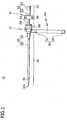
Fig. 1] Fig. 1 is a front view depicting the catheter introducer pertaining to a comparative example. - [
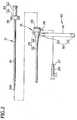
Fig. 2] Fig. 2 is a plan view depicting the catheter introducer which has been separated into the introducer sheath assembly and the dilator. - [
Fig. 3] Fig. 3 is a diagram showing how the introducer sheath assembly pertaining to the comparative example is mounted on the patient's wrist. - [
Fig. 4] Fig. 4 is a front view depicting the catheter introducer pertaining to an embodiment. - [
Fig. 5] Fig. 5 is a diagram showing how the introducer sheath assembly pertaining to the embodiment is mounted on the patient's wrist. - [
Fig. 6] Fig. 6 is a sectional view showing how to stop bleeding by pressing the incision with the hemostatic band. - [
Fig. 7A] Fig. 7A is a plan view showing a modification of the holding part possessed by the hemostatic band. - [
Fig. 7B] Fig. 7B is a plan view showing another modification of the holding part possessed by the hemostatic band. - [
Fig. 7C] Fig. 7C is a plan view showing a further modification of the holding part possessed by the hemostatic band. - The comparative example and the embodiment of the present invention will be described below with reference to the accompanying drawings, in which identical elements are given identical symbols to avoid repeated descriptions. The dimensions in the drawings are exaggerated for the sake of easy illustration and are different from actual ones.
- The catheter introducer 10 is a device that establishes the access route into the body cavity. Incidentally, the following description uses a term "proximal end" to denote that side of the device which is used for operation and a term "distal end" to denote that side of the device which is inserted into the body cavity.
- The catheter introducer 10 shown in
Figs. 1 and2 is composed of theintroducer sheath assembly 21 and thedilator 31. Theintroducer sheath assembly 21 is composed of theintroducer sheath 25 having thesheath tube 23 to be inserted into theincision 201 made in the skin of the patient's limb 200 (as shown inFig. 3 ) and thesheath hub 24 attached to the proximal end of thesheath tube 23. Theintroducer sheath assembly 21 further has thebelt 40 which is connected to thesheath hub 24 and wound around the patient'slimb 200 and the fasteningmember 50 which keeps thebelt 40 wound around thelimb 200. Thedilator 31 is composed of thedilator tube 32 and thedilator hub 33 attached to the proximal end of thedilator tube 32. Thedilator tube 32 is passed through thesheath tube 23 so that it functions as a core when thesheath tube 23 is inserted into theincision 201. After thesheath tube 23 has been inserted into theincision 201, that part indicated by thereference numeral 61 inFig. 1 which includes thesheath tube 23 and thedilator tube 32 dwells within the skin or blood vessel. In addition, that part indicated by thereference numeral 62 which includes thesheath hub 24 and thedilator hub 33 remains outside the skin. - The
introducer sheath 25 mentioned above is intended to facilitate insertion of the catheter, guide wire, wadding, etc. into the body cavity. - The
sheath tube 23 is introduced into the body cavity through the skin. Thesheath tube 23 is formed from any one or more as a mixture of polymeric materials including polyolefin (such as polyethylene, polypropylene, polybutene, ethylene-propylene copolymer, ethylene-vinyl acetate copolymer, ionomer, and a mixture of two or more thereof), polyolefin elastomer, cross-linked polyolefin, polyvinyl chloride, polyamide, polyamide elastomer, polyester, polyester elastomer, polyurethane, polyurethane elastomer, fluoroplastics, polycarbonate, polystyrene, polyacetal, polyimide, and polyetherimide. - The
sheath hub 24 has theside port 26 for communication with the inside of thesheath tube 23. Theside port 26, shown inFig. 2 , is fluid-tightly joined to one end of theflexible tube 27 made of polyvinyl chloride or the like. The other end of thetube 27 is connected to the three-way stopcock 28, which permits infusion of a fluid like physiological saline from a port thereof into theintroducer sheath 25 through thetube 27. At the proximal end of thesheath hub 24 is provided thehemostatic valve 29 which permits free passage of thedilator tube 32 and the catheter. Thesheath hub 24 is formed from a hard plastic material or the like, such as polyolefin such as polyethylene and polypropylene, polyamide, polycarbonate, and polystyrene. - The
dilator 31 mentioned above protects thesheath tube 23 against bending or expands the incision made on the skin when theintroducer sheath 25 is inserted into the blood vessel or the like. - The
dilator tube 32 is passed through thesheath tube 23, such that thetip 32a of thedilator tube 32 appears out of the tip of thesheath tube 23. Thedilator tube 32 may be formed from the same material as for thesheath tube 23. - The
dilator hub 33 is composed of the dilator hub proper 34 and theflange 35 attached to the distal end of the dilator hub proper 34. Theflange 35 has a plurality ofarms 36 extending therefrom toward the distal end. Thearms 36 are elastic such that they freely engage with and disengage from the proximal end of thesheath hub 24. Thedilator hub 33 may be formed from the same material as for thesheath hub 24. - According to the comparative example, the belt 40 (mentioned above) is constructed of the
belt member 41, with one end thereof connected to thesheath hub 24. Thebelt member 41 has a length more than enough to be wound around thelimb 200 and thesheath hub 24. - The
belt member 41 has a male part 51 (or a female part 52) of the hook-and-loop fastener 50 which is the one generally called MagicTape (registered trademark) in the neighborhood of one end of thebelt member 41 on the front side thereof (front side of the paper ofFig. 1 ). Thebelt member 41 also has the female part 52 (or the male part 51) of the hook-and-loop fastener 50 in the neighborhood of the other end of thebelt member 41 on the rear side thereof (rear side of the paper ofFig. 1 ). The hook-and-loop fastener 50 functions as a fastening member. - Operation of the comparative example will be explained below.
- The procedure to insert the
introducer sheath 25 into the artery in the wrist 200 (as a limb) includes the following steps. First, thedilator tube 32 is passed through thesheath tube 23. Next, thearms 36 of thedilator hub 33 are engaged with thesheath hub 24, so that theintroducer sheath 25 and thedilator 31 are firmly combined together. - The
sheath tube 23 is inserted into theincision 201. Thebelt member 41 is wound around thewrist 200 and thesheath hub 24 and fastened by means of themale part 51 andfemale part 52 of the hook-and-loop fastener 50. With this insertion step completed, thesheath tube 23 and thedilator tube 32 stay in the blood vessel and thesheath hub 24 anddilator hub 33 remain outside the skin. - After the
introducer sheath 25 has been inserted and fastened by thebelt member 41, thedilator hub 33 has itsarms 36 disengaged from thesheath hub 24 and thedilator 31 is withdrawn, with theintroducer sheath 25 left alone, as shown inFig. 3 . In this state, theintroducer sheath 25 functions as a passage between the blood vessel and the outside, and it permits the catheter or the like to be inserted into the blood vessel. - During the course of the procedures mentioned above, the
sheath hub 24 remains outside the skin and thedilator hub 33 also remains outside the skin until thedilator 31 is withdrawn. Being fastened to thewrist 200 by thebelt member 41 wound around thewrist 200, thesheath hub 24 is less liable to displacement and hence thesheath tube 23 is also less liable to displacement. - The
belt member 41, which is entirely wound around thewrist 200, pushes thesheath hub 24 wholly against thewrist 200 with a strong fastening force thereby fixing thesheath hub 24 move strongly. - Thus, the
sheath tube 23, which has been inserted into the blood vessel, is securely fastened to such an extent that it will not be displaced even though thesheath hub 24 or thedilator hub 33 is touched by the operator. This facilitates the manipulation of the catheter and guide wire. Moreover, the fact that thebelt member 41 is connected to thesheath hub 24 also facilitates the step of attaching theintroducer sheath 25 to thewrist 200. - The comparative example mentioned above demonstrates the mode in which the
belt member 41 is wound around thewrist 200 as well as thesheath hub 24. However, it is not necessary to wind the belt member around the sheath hub if the belt member and the sheath hub are fastened to each other. It is possible to fasten the belt member to the sheath hub by providing the sheath hub with wing-like flanges extending in both directions of the sheath hub so as to touch the limb, with one of the flanges fixed to one end of the belt member and the other end of the flanges fixed to the other end of the belt member by means of a hook-and-loop fastener. - The
belt 40 is not restricted in structure to thebelt member 41 mentioned above, but it may be variously modified according to need. According to the embodiment shown inFigs. 4 to 6 , thebelt 40 has thehemostatic band 42 which is so designed as to stop bleeding by theballoon 72 capable of expanding with a fluid filled into it, thereby pressing theincision 201. Thishemostatic band 42 is intended to stop bleeding from theincision 201 made in the skin of thewrist 200 after theintroducer sheath 25 used for insertion of the catheter or the like into the blood vessel for therapy and examination has been withdrawn. The embodiment of the present invention will be described below with reference toFigs. 4 to 6 , in which those elements common to the comparative example are given identical symbols to partly avoid repeated descriptions. - According to the embodiment, the
introducer sheath assembly 22 is composed of theintroducer sheath 25, thehemostatic band 42 as theband 40 which is connected to thesheath hub 24 and wound around thelimb 200, and the hook-and-loop fastener 50 which fastens thehemostatic band 42 wound around thelimb 200. - The
hemostatic band 42 includes the band proper 71, theballoon 72 that expands upon introduction of a fluid thereinto, and theauxiliary balloon 73 that overlaps with theballoon 72. Thehemostatic band 42 additionally has the holdingpart 80 which detachably holds theintroducer sheath 25. The holdingpart 80 includes thepocket 81 which accommodates and holds thesheath hub 24 and thewindow 82 which opens through thepocket 81 and permits thesheath tube 23 to pass through. Thewindow 82 is so arranged as to meet the position (incision 201) at which bleeding is to be stopped by theballoon 72. According to the illustrated embodiment, thewindow 82 lies on the extension of the line passing through the position that requires the stopping of bleeding and thepocket 81. The arrangement of thewindow 82 in this manner makes it possible to insert thesheath tube 23 at a desirable position of thewrist 200, without thepocket 81 interfering with thesheath tube 23 when thehemostatic band 42 is wound around the wrist 200 (SeeFig 5 ). - The band proper 71 is a flexible belt-like member. It is wound around the
wrist 200 and thesheath hub 24, with both ends thereof overlapping with each other. The band proper 71 is made of any translucent material for theincision 201 to be visible. Examples of such materials include polyvinyl chloride, polyolefins such as polyethylene, polypropylene, polybutadiene, and ethylene-vinyl acetate copolymer (EVA), polyesters such as polyethylene terephthalate (PET), and polybutylene terephthalate (PBT), thermoplastic elastomers such as polyvinylidene chloride, silicone, polyurethane, polyamide elastomer, polyurethane elastomer, and polyester elastomer, and a combination thereof (in the form of resin blend, polymer alloy, laminate, and the like). It is desirable that the band proper 71 is substantially transparent, so that the operator can see theincision 201 and the stopping of bleeding and can perform the positioning of the band proper 71. For the same reason as above, it is also desirable to use a substantially transparent material for theballoon 72, theauxiliary balloon 73, thepocket 81, and thebent plate 74 to be mentioned later. - The band proper 71 has at the center thereof the bent
plate holding part 75 to hold thebent plate 74. The bentplate holding part 75 has a gap to hold thebent plate 74. The band proper 71 holds thebent plate 74 in such a way that thebent plate 74, theballoon 72 and theauxiliary balloon 73 overlap with one another. Thebent plate 74 is made of a material which is stiffer than that used for the band proper 71, so that it maintains its shape. - The band proper 71 shown in
Fig. 4 has the male part 51 (or the female part 52) of the hook-and-loop fastener 50 on the inside (or the front side of the paper ofFig. 4 ) near the lower end thereof. Also, the band proper 71 shown inFig. 4 has the female part 52 (or the male part 51) of the hook-and-loop fastener 50 on the outside (or the back side of the paper ofFig. 4 ) near the upper end thereof. With the male andfemale parts loop fastener 50 joined together, the band proper 71 is fixed after it has been wound around thewrist 200 and thesheath hub 24. - The
balloon 72 and theauxiliary balloon 73 are made of any flexible material, so that they expand upon injection of a fluid (liquid or gas such as air) thereinto. Theballoon 72 takes on a square shape when it is collapsed. The material for theballoon 72 and theauxiliary balloon 73 is not specifically restricted so long as it makes theincision 201 visible. It may be the same one as mentioned above which is used for the band proper 71. As shown inFig. 6 , theballoon 72 is joined to the band proper 71 through the joining member 72a, and theauxiliary balloon 73 is joined to the band proper 71 through the joining member 73a. A portion of theballoon 72 and a portion of theauxiliary balloon 73 are joined to each other. In the joining part is formed the communicatingmember 76 for communication between the inside of theballoon 72 and the inside of theauxiliary balloon 73. The communicatingmember 76 permits the fluid, which has been injected into theballoon 72, to partly flow into theauxiliary balloon 73, so that theauxiliary balloon 73 expands as theballoon 72 expands. In this way it is possible to expand both of them by a single operation, which leads to efficient operation. - The
auxiliary balloon 73 is smaller in size than theballoon 72, so that theauxiliary balloon 73 locally presses theballoon 72. The direction of pressing is indicated by the arrow f inFig. 6 , which moves toward theapproximate center 202 of thewrist 200. The pressing force of theauxiliary balloon 73 causes theballoon 72 to apply a pressing force to theincision 201 in the direction indicated by the arrow F inFig. 6 . The direction of pressing (stressing) is not vertical (perpendicular to the surface of the wrist 200) but aslant (toward thecenter 202 of the wrist 200). Pressing in this manner is more effective for hemostatic action than pressing (stressing) theincision 201 in the vertical direction. - The
balloon 72 has the injectingmember 90 connected thereto, so that theballoon 72 can be filled with a fluid injected from the injectingmember 90, as shown inFig. 4 . The injectingmember 90 is composed of theflexible tube 91 whose proximal end connects with theballoon 72 and whose lumen communicates with the inside of theballoon 72, thebag 92 attached to the distal end of thetube 91, and thetubular connector 93 attached to thebag 92. Theballoon 72 is expanded (inflated) as the operator pushes the plunger of the syringe (not shown), whose distal end tip is inserted into theconnector 93, to inject a fluid into theballoon 72 through the injectingmember 90. After injection of a fluid into theballoon 72, the distal end tip of the syringe is withdrawn from theconnector 93. Theballoon 72 remains expanded because theconnector 93 has a check valve which closes to prevent the back flow of fluid. - The
pocket 81 is a bag-like object which holds therein thesheath hub 24. Thepocket 81 and theballoon 72 are joined to each other by fusion-bonding (with heating, high-frequency radiation, ultrasonic radiation, etc.) or adhesion (with adhesive or solvent). Thepocket 81 shown inFig. 4 has at the right edge thereof theopening 83 for insertion into which theintroducer sheath 25 is inserted and at the left edge thereof thewindow 82. Thesheath hub 24 tapers away toward its distal end. Theintroducer sheath 25 is inserted into thepocket 81 in such a way that the distal end of thesheath hub 24 reaches the inside of thepocket 81 and the root of thesheath tube 23 exposes itself outward from thewindow 82. Thewindow 82 has an inside diameter which is larger than the outside diameter of the tip of thesheath tube 23 and slightly smaller than the outside diameter of the root of thesheath tube 23, so that thesheath tube 23 which has been inserted into thepocket 81 does not displace unexpectedly. When theintroducer sheath 25 is inserted into the blood vessel, thesheath tube 23 is introduced into the blood vessel as far as its root reaches the blood vessel. After this procedure is complete and thesheath tube 23 is withdrawn, theincision 201 in which thesheath tube 23 was inserted is the position where bleeding should be stopped. As mentioned above, thewindow 82 is arranged on the extension of the line connecting the position at which bleeding is to be stopped by theballoon 72 and thepocket 81. In addition, theballoon 72 presses the area covering thewindow 82 of thepocket 81 and the root of thesheath tube 23. Therefore, it is possible to stop bleeding immediately, without necessity of rewinding thehemostatic band 42, by injecting a fluid into theballoon 72. - The position at which bleeding is to be stopped by the
balloon 72 should preferably be the center of theballoon 72 or the intersection of the diagonals of the square forming theballoon 72. This makes it possible to align the center of theballoon 72 with the neighborhood of theincision 201, so that theballoon 72 securely applies its pressing force to theincision 201 when it is expanded. - The
pocket 81 should preferably be formed from the same material as used for the band proper 71,balloon 72, and theauxiliary balloon 73, so that thepocket 81 and theballoon 72 are joined together easily or the band proper 71 and theballoons hemostatic band 42. - The
pocket 81 and theballoon 72 are not specifically restricted in dimensions; thepocket 81 may have a length L1 of about 14 mm and theballoon 72 may have a length L2 of about 38 mm. In addition, that part of thesheath tube 23 which is inserted into the living body may be about 5 mm exposed from thepocket 81. These dimensions are adequate for the device which is downsized and integrally composed of thehemostatic band 42 and theintroducer sheath 25, without thehemostatic band 42 being impaired in its function. - Operation of the embodiment will be explained below.
- The procedure to insert the
introducer sheath 25 into the artery in thewrist 200 is carried out in the same way as in the comparative example. That is, the first step is to integrally fix theintroducer sheath 25 and thedilator 31 together. - In the case where the
introducer sheath 25 is previously held in thepocket 81 of thehemostatic band 42, thesheath tube 23 is introduced into theincision 201 and then thehemostatic band 42 is wound around thewrist 200 and thesheath hub 24. Thehemostatic band 42 is fastened by means of themale part 51 andfemale part 52 of the hook-and-loop fastener 50 connected together while thehemostatic band 42 is wound around thewrist 200 and thesheath hub 24. This step may be changed in such a way that thehemostatic band 42 is wound around thewrist 200 and fixed and then thesheath tube 23 is introduced into theincision 201 while theintroducer sheath 25 is being held in thepocket 81. With this insertion step of thesheath tube 23 into theincision 201 completed, thesheath tube 23 and thedilator tube 32 stay in the blood vessel and thesheath hub 24 anddilator hub 33 remain outside the skin. - After the
introducer sheath 25 has been inserted and thehemostatic band 42 has been fastened, thedilator 31 is withdrawn, with theintroducer sheath 25 left alone, as shown inFig. 5 . The sheath permits the catheter or the like to be inserted into the blood vessel through it. - During the course of the procedures mentioned above, the
sheath hub 24 remains outside the skin and thedilator hub 33 also remains outside the skin until thedilator 31 is withdrawn. Being fastened to thewrist 200 by thehemostatic band 42 wound around thewrist 200, thesheath hub 24 is less liable to displacement and hence thesheath tube 23 is also less liable to displacement. - The
hemostatic band 42, which is entirely wound around thewrist 200, pushes thesheath hub 24 wholly against thewrist 200 with a strong fastening force thereby increasing the force fixing thesheath hub 24. - Thus, as in the case of the comparative example, the
sheath tube 23, which has been inserted into the blood vessel, is securely fastened to such an extent that it will not be displaced even though thesheath hub 24 or thedilator hub 33 is touched by the operator. This facilitates the manipulation of the catheter and guide wire. Moreover, the fact that thehemostatic band 42 is connected to thesheath hub 24 through thepocket 81 also facilitates the step of attaching theintroducer sheath 25 to thewrist 200. - Moreover, when the
sheath tube 23 has been withdrawn after completion of the procedure, theincision 201 for thesheath tube 23 is the position where bleeding is to be stopped by theballoon 72, and thewindow 82 of thepocket 81 coincides with the position where bleeding is to be stopped by theballoon 72. Consequently, the injection of a fluid into theballoon 72 immediately stops bleeding without the necessity of rewinding thehemostatic band 42. This allows a series of steps to stop bleeding after completion of the procedure to be carried out simply and rapidly, without the possibility of blood leakage. - At the time of stopping bleeding, a syringe (not shown) is connected to the
connector 93 of the injectingmember 90 and a fluid is injected into theballoon 72 and theauxiliary balloon 73, so that theballoon 72 and theauxiliary balloon 73 are expanded. The degree of expansion of theballoon 72 and theauxiliary balloon 73 or the degree of pressing force onto theincision 201 can be easily adjusted by varying the amount of fluid for injection. After theballoon 72 and theauxiliary balloon 73 have been expanded, the syringe is detached from theconnector 93 and then theintroducer sheath 25 is withdrawn from theincision 201. According to an alternative procedure, it is possible to withdraw theintroducer sheath 25 and then the fluid is injected into theballoon 72 and theauxiliary balloon 73. This procedure is desirable because thehemostatic band 42 has already been mounted to stop bleeding immediately. - As shown in
Fig. 6 , theballoon 72 and theauxiliary balloon 73 remain expanded and keep pressing theincision 201. In this state with theintroducer sheath 25 withdrawn, thepocket 81 takes on its original shape or collapsed shape. As theballoon 72 locally presses the incision 201 (and the neighborhood thereof) and theballoon 72 and theauxiliary balloon 73 expand, thecurved plate 74 separates from the surface of thewrist 200 and is made hard to touch thewrist 200. As the result, the incision 201 (and the neighborhood thereof) experiences a concentrated pressing force. This leads to a high hemostatic effect without pressing other blood vessels and nerves that do not need hemostasis. This is effective in preventing numbness and faulty circulation in the hand. - According to this embodiment, the
hemostatic band 42 is constructed such that it can be freely connected to theintroducer sheath 25. Therefore, it can be suitably applied to theintroducer sheath assembly 22, and it can also permit theintroducer sheath assembly 22 to produce the aforementioned effect and thehemostatic band 42 to fully produce its inherent hemostatic function. - The ordinary hemostatic belt has a marker for alignment of the balloon with the incision. However, in the case of the
introducer sheath assembly 22 according to the embodiment does not need such a marker to assist the positioning of theballoon 72 because theintroducer sheath 25 is integral with thehemostatic band 42 having the built-inballoon 72 and theballoon 72 presses the area including thewindow 82 of thepocket 81 and the root of thesheath tube 23. - Moreover, the holding
part 80 is constructed of thepocket 81 having thewindow 82, and this structure permits thehemostatic band 42 to hold theintroducer sheath 25 and also permits thehemostatic band 42 and theintroducer sheath 25 to remain connected each other by the simple procedure of inserting thesheath tube 23 and thesheath hub 24 into thepocket 81. - According to the embodiment, the
hemostatic band 42 is provided with thepocket 81 of bag-like simple structure which functions as the holdingpart 80 to hold theintroducer sheath 25. However, the holdingpart 80 is not restricted to the one constructed as mentioned above; it may be properly modified so long as it permits thehemostatic band 42 to hold theintroducer sheath 25. An example of modification of the holdingpart 80 will be described below with reference toFigs. 7(A) to 7(C) , in which those elements common to the embodiment are given identical symbols to partly avoid repeated descriptions. - The holding
part 80 may be constructed as shown inFig. 7(A) . That is, it is composed of the supportingmember 84 attached to theballoon 72 and therecess 85 which is formed in the supportingmember 84 and capable of receiving theprojection 86 fitted thereinto which is previously formed on thesheath hub 24. Theprojection 86 formed on thesheath hub 24 is fitted into therecess 85 formed in the supportingmember 84. This simple step permits thehemostatic band 42 to hold theintroducer sheath 25, so that thehemostatic band 42 and theintroducer sheath 25 remain connected to each other. - The supporting
member 84 may be made of the same material as theballoon 72 and theauxiliary balloon 73. The supportingmember 84 is attached to thehemostatic band 42 by fusion bonding. The material for the supportingmember 84 and the method for attaching the supportingmember 84 to thehemostatic band 42 are not restricted to those mentioned above and changes and modifications will be made appropriately. - The shape and position of the
recess 85 are not specifically restricted, and the shape and position of theprojections 86 are not specifically restricted. They may be appropriately changed and modified so long as they permit thehemostatic band 42 and theintroducer sheath 25 to remain connected to each other. For example, the projection may be formed on the supportingmember 84 and the recess may be formed in theintroducer sheath 25. - As shown in
Fig. 7(B) , the holdingpart 80 may be composed of the supportingmember 84 attached to theballoon 72 and the slit-like groove 87 which is formed in the supportingmember 84 and permits thesheath tube 23 to be inserted into thegroove 87 formed in the supportingmember 84. Thesheath tube 23 is inserted into thegroove 87 formed in the supportingmember 84. This simple step permits thehemostatic band 42 to hold theintroducer sheath 25, so that thehemostatic band 42 and theintroducer sheath 25 remain connected to each other. - The supporting
member 84 is made of flexible rubber material, and the width of the slit of thegroove 87 is slightly narrower than the outside diameter of thesheath tube 23. Therefore, thesheath tube 23 can be easily inserted into thegroove 87 by expanding the slit. After insertion, thesheath tube 23 is tightened with a comparatively weak force, so that the displacement of thesheath tube 23 is protected. Incidentally, the rubber material may be elastomer resin, and the supportingmember 84 may be attached to thehemostatic band 42 by fusion bonding or adhesion. - The shape of the slit and position of the
groove 87 are not specifically restricted but appropriately changed and modified so long as they permit thehemostatic band 42 and theintroducer sheath 25 to remain connected to each other. A possible modification may be such that other part than thesheath tube 23 of theintroducer sheath 25 is inserted into thegroove 87. In this case, the shape and position of thegroove 87 may be appropriately changed according to the shape and position of the parts into which theintroducer sheath 25 is inserted. Any other part than thesheath tube 23 for insertion may be thesheath hub 24. - The holding
part 80 may be constructed of thepocket 81 having the holding hook-and-loop fastener 88, as shown inFig. 7(C) . The holding hook-and-loop fastener 88 is provided at the adjacent two sides of thepocket 81. One side (the left side in the figure) at which the holding hook-and-loop fastener 88 is provided may have the fastening part which holds a portion (say, suture eye) of thesheath hub 24 of theintroducer sheath 25. The other side (the lower side in the figure) at which the holding hook-and-loop fastener 88 is provided has the part to hold and fasten the sheath,tube 23. The other side further has thewindow 82 for thesheath tube 23 to pass through. That side on which the holding hook-and-loop fastener 88 is not provided has theinsertion opening 83 through which theintroducer sheath 25 is inserted into thepocket 81. - At the time of use, the
sheath tube 23 and thesheath hub 24 are inserted into thepocket 81 through the insertion opening 83 (as indicated by the arrow a in the figure). Thehemostatic band 42 is caused to hold theintroducer sheath 25 by means of the holding hook-and-loop fastener 88. In this way theintroducer sheath 25 is securely held without the possibility of displacement because thesheath hub 24 is fastened to one side of thepocket 81 and thesheath tube 23 is fastened to the other side of thepocket 81. Theintroducer sheath 25 is fastened simply by using the holding hook-and-loop fastener 88, and thehemostatic band 42 and theintroducer sheath 25 remain connected to each other. - The
pocket 81 is made of the material identical or equivalent to that of theballoon 72 and theauxiliary balloon 73. Thepocket 81 and thehemostatic band 42 are attached by fusion bonding. The material for thepocket 81 and the method for attaching thepocket 81 to thehemostatic band 42 are not restricted to those mentioned above; they may be changed and modified appropriately. The positions at which thepocket 81 and holding hook-and-loop fastener 88 are attached are not restricted either. They may be changed appropriately so long as they permit thehemostatic band 42 and theintroducer sheath 25 to remain connected to each other. - The
introducer sheath assemblies hemostatic band 42 according to the present invention have been described above with reference to the illustrated embodiment. However, the scope of the present invention is not restricted to the one mentioned above, and the constituents of theintroducer sheath assemblies hemostatic band 42 may be replaced by any ones capable of exhibiting the equivalent functions. Furthermore, any constituents may be added. - For example, the hook-and-
loop fastener 50 provided on thebelt member 41 as thebelt 40 and thehemostatic band 42 may be replaced by any member which fastens thebelt 40 and thesheath hub 24 which are wound around thewrist 200. Such a member is exemplified by a snap, button, clip, and frame (passing through the edge of the belt 40). - The foregoing demonstrates an embodiment in which the marker to indicate the position for hemostasis is omitted. The embodiment may be modified such that a marker is attached to the
balloon 72. If theballoon 72 is provided with a marker at the position corresponding to theincision 201 where thesheath tube 23 is inserted, the operator is able to clearly recognize the position for hemostasis. - The
introducer sheath assemblies hemostatic band 42 are not limited to be mounted on thewrist 200 and theintroducer sheath assemblies hemostatic band 42 may be mounted on the arm and leg (which are generally referred to as limbs in this specification). - 10 ...
- Catheter introducer,
- 21, 22 ...
- Introducer sheath assembly,
- 23 ...
- Sheath tube,
- 24 ...
- Sheath hub,
- 25 ...
- Introducer sheath,
- 31 ...
- Dilator,
- 32 ...
- Dilator tube,
- 33 ...
- Dilator hub,
- 40 ...
- Belt,
- 41 ...
- Belt member (belt),
- 42 ...
- Hemostatic band (belt),
- 50 ...
- Hook-and-loop fastener (fastening member),
- 51 ...
- Male part of hook-and-loop fastener,
- 52 ...
- Female part of the hook-and-loop fastener,
- 71 ...
- Band proper,
- 72 ...
- Balloon,
- 73 ...
- Auxiliary balloon,
- 80 ...
- Holding part,
- 81 ...
- Pocket,
- 82 ...
- Window,
- 83 ...
- Insertion opening,
- 84 ...
- Supporting member,
- 85 ...
- Recess,
- 86 ...
- Projection,
- 87 ...
- Groove,
- 88 ...
- Holding hook-and-loop fastener,
- 90 ...
- Injecting part,
- 200 ...
- Wrist (limb),
- 201 ...
- Incision (where the balloon stops bleeding).
Claims (3)
- A hemostatic band (42) suitable to be connected in any way with an introducer sheath (25) having a sheath tube (23) suitable to be introduced into an incision (201) of a limb (200) and a sheath hub (24) attached to the proximal end of the sheath tube (23), wherein
the hemostatic band (42) comprises:a band suitable to be wound around the limb (200);a balloon (72) which is attached to the band and stops bleeding by pressing the incision (201) as it is expanded with a fluid injected thereinto; anda fastening member (50) which holds the band in such a state that it is wound around the limb (200); anda holding part (80) which is attached to the band and suitable to permit the introducer sheath (25) to be detachably attached,characterized in thatthe holding part (80) is composed of a pocket (81), which is suitable to accommodate and hold the sheath hub (24), and a window (82) which opens in the pocket (81) and is suitable to pass the sheath tube (23) through it, the window (82) being arranged in conformity with the part where bleeding is stopped by the balloon (72). - The hemostatic band (42) according to claim 1, wherein the pocket (81) is a bag-like object which is suitable to hold therein the sheath hub (24).
- The hemostatic band (42) according to claim 1, wherein the pocket (81) and the balloon (72) are joined to each other by fusion-bonding or adhesion.
Applications Claiming Priority (2)
| Application Number | Priority Date | Filing Date | Title |
|---|---|---|---|
| JP2010074563 | 2010-03-29 | ||
| PCT/JP2011/057427WO2011122488A1 (en) | 2010-03-29 | 2011-03-25 | Introducer sheath assembly |
Publications (3)
| Publication Number | Publication Date |
|---|---|
| EP2529782A1 EP2529782A1 (en) | 2012-12-05 |
| EP2529782A4 EP2529782A4 (en) | 2013-09-11 |
| EP2529782B1true EP2529782B1 (en) | 2016-06-22 |
Family
ID=44712195
Family Applications (1)
| Application Number | Title | Priority Date | Filing Date |
|---|---|---|---|
| EP11762719.0AActiveEP2529782B1 (en) | 2010-03-29 | 2011-03-25 | Hemostatic band |
Country Status (6)
| Country | Link |
|---|---|
| US (1) | US9089335B2 (en) |
| EP (1) | EP2529782B1 (en) |
| JP (1) | JP5844730B2 (en) |
| CN (1) | CN102834139B (en) |
| AU (1) | AU2011232934B2 (en) |
| WO (1) | WO2011122488A1 (en) |
Families Citing this family (30)
| Publication number | Priority date | Publication date | Assignee | Title |
|---|---|---|---|---|
| US10089443B2 (en) | 2012-05-15 | 2018-10-02 | Baxter International Inc. | Home medical device systems and methods for therapy prescription and tracking, servicing and inventory |
| US9782199B2 (en)* | 2012-03-23 | 2017-10-10 | Mitsubishi Pencil Company, Limited | Puncture device |
| US11564697B2 (en)* | 2013-07-12 | 2023-01-31 | Vasoinnovations Inc. | Apparatus and method to stop bleeding |
| US20170172654A1 (en)* | 2014-02-11 | 2017-06-22 | St. Jude Medical, Cardiology Division, Inc. | Ablation catheter and associated methods |
| JP6559128B2 (en)* | 2014-06-27 | 2019-08-14 | テルモ株式会社 | Hemostatic device |
| DE102014014015A1 (en) | 2014-09-26 | 2016-03-31 | Bentley Innomed Gmbh | Stretchable introducer sheath |
| EP3345555B1 (en) | 2015-09-03 | 2020-10-21 | Terumo Kabushiki Kaisha | Hemostatic instrument |
| WO2018017365A1 (en) | 2016-07-18 | 2018-01-25 | Merit Medical Systems, Inc. | Inflatable radial artery compression device |
| CN109640842A (en)* | 2016-08-17 | 2019-04-16 | 波士顿科学有限公司 | Sleeve pipe with integrated closing device |
| WO2018043427A1 (en) | 2016-09-01 | 2018-03-08 | テルモ株式会社 | Introducer sheath |
| JP6797612B2 (en) | 2016-09-01 | 2020-12-09 | テルモ株式会社 | Introducer sheath |
| CN106108971B (en)* | 2016-09-21 | 2018-07-13 | 南昌大学第二附属医院 | Multi-functional torniquet and chair |
| US10173035B2 (en) | 2016-12-27 | 2019-01-08 | Vasonics, Llc | Catheter housing |
| RU2733046C1 (en) | 2017-03-29 | 2020-09-28 | Терумо Кабусики Кайся | Haemostatic device and haemostatic method |
| US11134957B2 (en)* | 2017-09-01 | 2021-10-05 | Stat Band, LLC | Transradial sheath support and hemostasis device and method |
| US11284905B2 (en) | 2017-11-03 | 2022-03-29 | Merit Medical Systems, Inc. | Hemostasis devices and methods of use |
| JP2021515654A (en)* | 2018-03-09 | 2021-06-24 | メリット・メディカル・システムズ・インコーポレイテッドMerit Medical Systems,Inc. | Ultrasound-compatible inflatable vascular compression and related systems and methods |
| WO2019199969A1 (en) | 2018-04-11 | 2019-10-17 | Merit Medical Systems, Inc. | Inflatable compression device |
| EP3790618A1 (en)* | 2018-05-08 | 2021-03-17 | Boston Scientific Scimed Inc. | Wristband with hemostatic valve for sheathless transradial procedure |
| US11857320B2 (en) | 2018-06-08 | 2024-01-02 | Smiths Medical Asd, Inc. | Blood sequestration device and method |
| US11628276B2 (en) | 2018-06-25 | 2023-04-18 | Vasonics, Inc. | Catheter securement, stabilization, and antimicrobial device |
| CN109200432A (en)* | 2018-10-24 | 2019-01-15 | 深圳麦科田生命科学有限公司 | catheter sheath |
| JP2022029463A (en)* | 2018-11-29 | 2022-02-18 | テルモ株式会社 | Hemostatic device |
| CN109646789B (en)* | 2019-01-28 | 2024-03-08 | 中国人民解放军陆军军医大学第一附属医院 | Safety vascular sheath device |
| CN109567910B (en)* | 2019-01-28 | 2023-09-22 | 中国人民解放军陆军军医大学第一附属医院 | Multifunctional vascular intervention puncture device and application method thereof |
| JP2020124349A (en)* | 2019-02-04 | 2020-08-20 | 有限会社イーブイエフ製作所 | Treatment device |
| CN112915364B (en)* | 2021-03-09 | 2022-06-10 | 杨都江 | Acute pancreatitis is tee bend pipe for minimal access surgery |
| US11638588B2 (en)* | 2021-06-14 | 2023-05-02 | Fahed Bitar | Radial artery sheath assembly |
| US12426864B2 (en) | 2021-06-18 | 2025-09-30 | Merit Medical Systems, Inc. | Hemostasis devices and methods of use |
| EP4460243A1 (en)* | 2022-01-05 | 2024-11-13 | Becton, Dickinson and Company | Dressing-based traction apparatus with integrated tourniquet for improved blood draw |
Family Cites Families (24)
| Publication number | Priority date | Publication date | Assignee | Title |
|---|---|---|---|---|
| US3675656A (en)* | 1969-05-26 | 1972-07-11 | Salomon Hakim | Fluid operatable hemostat |
| US4314568A (en)* | 1980-01-11 | 1982-02-09 | Baxter Travenol Laboratories, Inc. | Vascular stabilizer |
| US4591356A (en)* | 1984-06-06 | 1986-05-27 | Christie Barbara C | Intravenous needle stabilizing band |
| EP0462088B1 (en)* | 1990-06-11 | 1995-11-08 | Radi Medical Systems Ab | Femoral compression device |
| US5433724A (en)* | 1991-04-23 | 1995-07-18 | Sumitomo Rubber Industries, Ltd. | Compressive hemostatic belt |
| US5464420A (en)* | 1992-02-06 | 1995-11-07 | Sumitomo Rubber Industries, Ltd. | Compressive hemostatic belt |
| US5269803A (en)* | 1992-04-10 | 1993-12-14 | Gtr Patent, Inc. | Hemostasis pressure pad band |
| DE69320769T2 (en)* | 1992-12-04 | 1999-01-14 | Sumitomo Rubber Industries, Ltd., Kobe, Hyogo | Hemostatic pressure belt |
| DE69427716T2 (en)* | 1993-03-10 | 2002-06-13 | Nichiban Co. Ltd., Tokio/Tokyo | Adhesive bandage for hemostasis |
| IL107411A0 (en)* | 1993-10-27 | 1994-01-25 | Wolman Michael | Infusion administering catheter holder |
| US5968072A (en)* | 1993-12-20 | 1999-10-19 | Medical Wraps, Inc. | Method and apparatus for cold compression treatment of wounds |
| JPH11206888A (en)* | 1998-01-20 | 1999-08-03 | Clinical Supply:Kk | Implement for insertion into blood vessel |
| CN2429120Y (en)* | 2000-07-07 | 2001-05-09 | 赵宏伟 | Inflating emergency hemostatic apparatus |
| US20040068290A1 (en)* | 2002-03-27 | 2004-04-08 | Datascope Investment Corp. | Device and method for compressing wounds |
| JP4125095B2 (en)* | 2002-11-07 | 2008-07-23 | テルモ株式会社 | Hemostatic device |
| EP2070483B1 (en)* | 2002-07-15 | 2011-02-16 | Terumo Kabushiki Kaisha | Hemostatic device with inflatable balloon |
| AU2005269228B2 (en)* | 2004-08-04 | 2011-04-28 | Bradley Allan Ross | Adjustable tissue compression device |
| GB0518922D0 (en)* | 2005-09-16 | 2005-10-26 | Shams Iden | Infusion line stabiliser |
| US8162890B2 (en) | 2006-05-16 | 2012-04-24 | Flexicath Ltd. | Catheter insertion apparatus and method of use thereof |
| US8657850B2 (en)* | 2008-05-06 | 2014-02-25 | Merit Medical Systems, Inc. | Radial artery compression device |
| US8353927B2 (en)* | 2009-05-04 | 2013-01-15 | Merit Medical Systems, Inc. | Radial artery compression device |
| JP2009291380A (en)* | 2008-06-04 | 2009-12-17 | Deiisurii Kk | Medical instrument having incorrect needle removal preventive function and hemostatic function |
| CN201220032Y (en)* | 2008-07-14 | 2009-04-15 | 齐宝琴 | Strap for securing venous indwelling needle |
| JP2010074563A (en) | 2008-09-18 | 2010-04-02 | Sumitomo Metal Electronics Devices Inc | Circuit board and high-frequency package for housing the same |
- 2011
- 2011-03-25EPEP11762719.0Apatent/EP2529782B1/enactiveActive
- 2011-03-25AUAU2011232934Apatent/AU2011232934B2/enactiveActive
- 2011-03-25JPJP2012508263Apatent/JP5844730B2/enactiveActive
- 2011-03-25WOPCT/JP2011/057427patent/WO2011122488A1/enactiveApplication Filing
- 2011-03-25CNCN201180017027.6Apatent/CN102834139B/enactiveActive
- 2012
- 2012-09-27USUS13/629,264patent/US9089335B2/enactiveActive
Also Published As
| Publication number | Publication date |
|---|---|
| AU2011232934B2 (en) | 2013-07-11 |
| AU2011232934A1 (en) | 2012-08-30 |
| EP2529782A1 (en) | 2012-12-05 |
| EP2529782A4 (en) | 2013-09-11 |
| WO2011122488A1 (en) | 2011-10-06 |
| CN102834139A (en) | 2012-12-19 |
| JPWO2011122488A1 (en) | 2013-07-08 |
| JP5844730B2 (en) | 2016-01-20 |
| US9089335B2 (en) | 2015-07-28 |
| US20130023734A1 (en) | 2013-01-24 |
| CN102834139B (en) | 2015-03-25 |
Similar Documents
| Publication | Publication Date | Title |
|---|---|---|
| EP2529782B1 (en) | Hemostatic band | |
| CN110461255B (en) | Hemostatic device and hemostatic method | |
| US10569057B2 (en) | Integrated vascular delivery system | |
| JP7071398B2 (en) | Vascular access device | |
| US7498477B2 (en) | Hemostatic device | |
| CN108024817B (en) | hemostatic device | |
| US6796972B1 (en) | Catheter anchoring balloon structure with irrigation | |
| US20080319387A1 (en) | Method and Apparatus for Inserting a Catheter Device | |
| EP3434204B1 (en) | Hemostatic instrument | |
| US20180008282A1 (en) | Hemostatic device | |
| AU2017237281A1 (en) | Hemostatic device | |
| US8512293B2 (en) | Valves and hubs for tubular medical devices and methods for making and using them | |
| BRMU9100084Y1 (en) | HEMOSTATIC DEVICE | |
| JP4398747B2 (en) | Hemostatic device | |
| CN212213844U (en) | A expansion guiding device for intervene treatment | |
| JP2024049569A (en) | Hemostatic device | |
| JP2002119598A (en) | Indwelling balloon intracatheter | |
| JP2025104535A (en) | hemostasis device | |
| JP2024017621A (en) | Hemostatic device | |
| CN115105740A (en) | Vascular sheath hemostasis valve and collateral branch pipe connection structure | |
| RU2163151C1 (en) | Subclavian catheter | |
| JP2002119597A (en) | Indwelling balloon intracatheter | |
| JPH0362112B2 (en) |
Legal Events
| Date | Code | Title | Description |
|---|---|---|---|
| PUAI | Public reference made under article 153(3) epc to a published international application that has entered the european phase | Free format text:ORIGINAL CODE: 0009012 | |
| 17P | Request for examination filed | Effective date:20120827 | |
| AK | Designated contracting states | Kind code of ref document:A1 Designated state(s):AL AT BE BG CH CY CZ DE DK EE ES FI FR GB GR HR HU IE IS IT LI LT LU LV MC MK MT NL NO PL PT RO RS SE SI SK SM TR | |
| DAX | Request for extension of the european patent (deleted) | ||
| A4 | Supplementary search report drawn up and despatched | Effective date:20130813 | |
| RIC1 | Information provided on ipc code assigned before grant | Ipc:A61B 17/132 20060101ALI20130807BHEP Ipc:A61M 25/00 20060101ALI20130807BHEP Ipc:A61M 29/00 20060101ALI20130807BHEP Ipc:A61M 25/02 20060101AFI20130807BHEP Ipc:A61B 17/135 20060101ALI20130807BHEP | |
| 17Q | First examination report despatched | Effective date:20150601 | |
| REG | Reference to a national code | Ref country code:DE Ref legal event code:R079 Ref document number:602011027577 Country of ref document:DE Free format text:PREVIOUS MAIN CLASS: A61M0025080000 Ipc:A61M0025020000 | |
| GRAP | Despatch of communication of intention to grant a patent | Free format text:ORIGINAL CODE: EPIDOSNIGR1 | |
| RIC1 | Information provided on ipc code assigned before grant | Ipc:A61M 25/02 20060101AFI20160111BHEP Ipc:A61B 17/132 20060101ALI20160111BHEP Ipc:A61M 29/00 20060101ALI20160111BHEP Ipc:A61M 25/00 20060101ALI20160111BHEP Ipc:A61B 17/135 20060101ALI20160111BHEP Ipc:A61M 25/06 20060101ALN20160111BHEP | |
| INTG | Intention to grant announced | Effective date:20160216 | |
| GRAS | Grant fee paid | Free format text:ORIGINAL CODE: EPIDOSNIGR3 | |
| GRAA | (expected) grant | Free format text:ORIGINAL CODE: 0009210 | |
| AK | Designated contracting states | Kind code of ref document:B1 Designated state(s):AL AT BE BG CH CY CZ DE DK EE ES FI FR GB GR HR HU IE IS IT LI LT LU LV MC MK MT NL NO PL PT RO RS SE SI SK SM TR | |
| REG | Reference to a national code | Ref country code:GB Ref legal event code:FG4D | |
| REG | Reference to a national code | Ref country code:CH Ref legal event code:EP | |
| REG | Reference to a national code | Ref country code:IE Ref legal event code:FG4D | |
| REG | Reference to a national code | Ref country code:AT Ref legal event code:REF Ref document number:807305 Country of ref document:AT Kind code of ref document:T Effective date:20160715 | |
| REG | Reference to a national code | Ref country code:NL Ref legal event code:FP | |
| REG | Reference to a national code | Ref country code:DE Ref legal event code:R096 Ref document number:602011027577 Country of ref document:DE | |
| REG | Reference to a national code | Ref country code:LT Ref legal event code:MG4D | |
| PG25 | Lapsed in a contracting state [announced via postgrant information from national office to epo] | Ref country code:NO Free format text:LAPSE BECAUSE OF FAILURE TO SUBMIT A TRANSLATION OF THE DESCRIPTION OR TO PAY THE FEE WITHIN THE PRESCRIBED TIME-LIMIT Effective date:20160922 Ref country code:LT Free format text:LAPSE BECAUSE OF FAILURE TO SUBMIT A TRANSLATION OF THE DESCRIPTION OR TO PAY THE FEE WITHIN THE PRESCRIBED TIME-LIMIT Effective date:20160622 Ref country code:FI Free format text:LAPSE BECAUSE OF FAILURE TO SUBMIT A TRANSLATION OF THE DESCRIPTION OR TO PAY THE FEE WITHIN THE PRESCRIBED TIME-LIMIT Effective date:20160622 | |
| REG | Reference to a national code | Ref country code:AT Ref legal event code:MK05 Ref document number:807305 Country of ref document:AT Kind code of ref document:T Effective date:20160622 | |
| PG25 | Lapsed in a contracting state [announced via postgrant information from national office to epo] | Ref country code:RS Free format text:LAPSE BECAUSE OF FAILURE TO SUBMIT A TRANSLATION OF THE DESCRIPTION OR TO PAY THE FEE WITHIN THE PRESCRIBED TIME-LIMIT Effective date:20160622 Ref country code:GR Free format text:LAPSE BECAUSE OF FAILURE TO SUBMIT A TRANSLATION OF THE DESCRIPTION OR TO PAY THE FEE WITHIN THE PRESCRIBED TIME-LIMIT Effective date:20160923 Ref country code:SE Free format text:LAPSE BECAUSE OF FAILURE TO SUBMIT A TRANSLATION OF THE DESCRIPTION OR TO PAY THE FEE WITHIN THE PRESCRIBED TIME-LIMIT Effective date:20160622 Ref country code:HR Free format text:LAPSE BECAUSE OF FAILURE TO SUBMIT A TRANSLATION OF THE DESCRIPTION OR TO PAY THE FEE WITHIN THE PRESCRIBED TIME-LIMIT Effective date:20160622 Ref country code:LV Free format text:LAPSE BECAUSE OF FAILURE TO SUBMIT A TRANSLATION OF THE DESCRIPTION OR TO PAY THE FEE WITHIN THE PRESCRIBED TIME-LIMIT Effective date:20160622 | |
| PG25 | Lapsed in a contracting state [announced via postgrant information from national office to epo] | Ref country code:CZ Free format text:LAPSE BECAUSE OF FAILURE TO SUBMIT A TRANSLATION OF THE DESCRIPTION OR TO PAY THE FEE WITHIN THE PRESCRIBED TIME-LIMIT Effective date:20160622 Ref country code:EE Free format text:LAPSE BECAUSE OF FAILURE TO SUBMIT A TRANSLATION OF THE DESCRIPTION OR TO PAY THE FEE WITHIN THE PRESCRIBED TIME-LIMIT Effective date:20160622 Ref country code:RO Free format text:LAPSE BECAUSE OF FAILURE TO SUBMIT A TRANSLATION OF THE DESCRIPTION OR TO PAY THE FEE WITHIN THE PRESCRIBED TIME-LIMIT Effective date:20160622 Ref country code:SK Free format text:LAPSE BECAUSE OF FAILURE TO SUBMIT A TRANSLATION OF THE DESCRIPTION OR TO PAY THE FEE WITHIN THE PRESCRIBED TIME-LIMIT Effective date:20160622 Ref country code:IS Free format text:LAPSE BECAUSE OF FAILURE TO SUBMIT A TRANSLATION OF THE DESCRIPTION OR TO PAY THE FEE WITHIN THE PRESCRIBED TIME-LIMIT Effective date:20161022 Ref country code:IT Free format text:LAPSE BECAUSE OF FAILURE TO SUBMIT A TRANSLATION OF THE DESCRIPTION OR TO PAY THE FEE WITHIN THE PRESCRIBED TIME-LIMIT Effective date:20160622 | |
| REG | Reference to a national code | Ref country code:FR Ref legal event code:PLFP Year of fee payment:7 | |
| PG25 | Lapsed in a contracting state [announced via postgrant information from national office to epo] | Ref country code:SM Free format text:LAPSE BECAUSE OF FAILURE TO SUBMIT A TRANSLATION OF THE DESCRIPTION OR TO PAY THE FEE WITHIN THE PRESCRIBED TIME-LIMIT Effective date:20160622 Ref country code:ES Free format text:LAPSE BECAUSE OF FAILURE TO SUBMIT A TRANSLATION OF THE DESCRIPTION OR TO PAY THE FEE WITHIN THE PRESCRIBED TIME-LIMIT Effective date:20160622 Ref country code:AT Free format text:LAPSE BECAUSE OF FAILURE TO SUBMIT A TRANSLATION OF THE DESCRIPTION OR TO PAY THE FEE WITHIN THE PRESCRIBED TIME-LIMIT Effective date:20160622 Ref country code:PL Free format text:LAPSE BECAUSE OF FAILURE TO SUBMIT A TRANSLATION OF THE DESCRIPTION OR TO PAY THE FEE WITHIN THE PRESCRIBED TIME-LIMIT Effective date:20160622 Ref country code:BE Free format text:LAPSE BECAUSE OF FAILURE TO SUBMIT A TRANSLATION OF THE DESCRIPTION OR TO PAY THE FEE WITHIN THE PRESCRIBED TIME-LIMIT Effective date:20160622 Ref country code:PT Free format text:LAPSE BECAUSE OF FAILURE TO SUBMIT A TRANSLATION OF THE DESCRIPTION OR TO PAY THE FEE WITHIN THE PRESCRIBED TIME-LIMIT Effective date:20161024 | |
| REG | Reference to a national code | Ref country code:DE Ref legal event code:R097 Ref document number:602011027577 Country of ref document:DE | |
| PLBE | No opposition filed within time limit | Free format text:ORIGINAL CODE: 0009261 | |
| STAA | Information on the status of an ep patent application or granted ep patent | Free format text:STATUS: NO OPPOSITION FILED WITHIN TIME LIMIT | |
| 26N | No opposition filed | Effective date:20170323 | |
| PG25 | Lapsed in a contracting state [announced via postgrant information from national office to epo] | Ref country code:DK Free format text:LAPSE BECAUSE OF FAILURE TO SUBMIT A TRANSLATION OF THE DESCRIPTION OR TO PAY THE FEE WITHIN THE PRESCRIBED TIME-LIMIT Effective date:20160622 | |
| PG25 | Lapsed in a contracting state [announced via postgrant information from national office to epo] | Ref country code:SI Free format text:LAPSE BECAUSE OF FAILURE TO SUBMIT A TRANSLATION OF THE DESCRIPTION OR TO PAY THE FEE WITHIN THE PRESCRIBED TIME-LIMIT Effective date:20160622 | |
| REG | Reference to a national code | Ref country code:CH Ref legal event code:PL | |
| PG25 | Lapsed in a contracting state [announced via postgrant information from national office to epo] | Ref country code:MC Free format text:LAPSE BECAUSE OF FAILURE TO SUBMIT A TRANSLATION OF THE DESCRIPTION OR TO PAY THE FEE WITHIN THE PRESCRIBED TIME-LIMIT Effective date:20160622 | |
| REG | Reference to a national code | Ref country code:IE Ref legal event code:MM4A | |
| PG25 | Lapsed in a contracting state [announced via postgrant information from national office to epo] | Ref country code:LU Free format text:LAPSE BECAUSE OF NON-PAYMENT OF DUE FEES Effective date:20170325 | |
| REG | Reference to a national code | Ref country code:FR Ref legal event code:PLFP Year of fee payment:8 | |
| PG25 | Lapsed in a contracting state [announced via postgrant information from national office to epo] | Ref country code:CH Free format text:LAPSE BECAUSE OF NON-PAYMENT OF DUE FEES Effective date:20170331 Ref country code:IE Free format text:LAPSE BECAUSE OF NON-PAYMENT OF DUE FEES Effective date:20170325 Ref country code:LI Free format text:LAPSE BECAUSE OF NON-PAYMENT OF DUE FEES Effective date:20170331 | |
| PG25 | Lapsed in a contracting state [announced via postgrant information from national office to epo] | Ref country code:MT Free format text:LAPSE BECAUSE OF NON-PAYMENT OF DUE FEES Effective date:20170325 | |
| PG25 | Lapsed in a contracting state [announced via postgrant information from national office to epo] | Ref country code:AL Free format text:LAPSE BECAUSE OF FAILURE TO SUBMIT A TRANSLATION OF THE DESCRIPTION OR TO PAY THE FEE WITHIN THE PRESCRIBED TIME-LIMIT Effective date:20160622 | |
| PG25 | Lapsed in a contracting state [announced via postgrant information from national office to epo] | Ref country code:HU Free format text:LAPSE BECAUSE OF FAILURE TO SUBMIT A TRANSLATION OF THE DESCRIPTION OR TO PAY THE FEE WITHIN THE PRESCRIBED TIME-LIMIT; INVALID AB INITIO Effective date:20110325 | |
| PG25 | Lapsed in a contracting state [announced via postgrant information from national office to epo] | Ref country code:BG Free format text:LAPSE BECAUSE OF FAILURE TO SUBMIT A TRANSLATION OF THE DESCRIPTION OR TO PAY THE FEE WITHIN THE PRESCRIBED TIME-LIMIT Effective date:20160622 | |
| PG25 | Lapsed in a contracting state [announced via postgrant information from national office to epo] | Ref country code:CY Free format text:LAPSE BECAUSE OF NON-PAYMENT OF DUE FEES Effective date:20160622 | |
| PG25 | Lapsed in a contracting state [announced via postgrant information from national office to epo] | Ref country code:MK Free format text:LAPSE BECAUSE OF FAILURE TO SUBMIT A TRANSLATION OF THE DESCRIPTION OR TO PAY THE FEE WITHIN THE PRESCRIBED TIME-LIMIT Effective date:20160622 | |
| PG25 | Lapsed in a contracting state [announced via postgrant information from national office to epo] | Ref country code:TR Free format text:LAPSE BECAUSE OF FAILURE TO SUBMIT A TRANSLATION OF THE DESCRIPTION OR TO PAY THE FEE WITHIN THE PRESCRIBED TIME-LIMIT Effective date:20160622 | |
| PGFP | Annual fee paid to national office [announced via postgrant information from national office to epo] | Ref country code:NL Payment date:20250217 Year of fee payment:15 | |
| PGFP | Annual fee paid to national office [announced via postgrant information from national office to epo] | Ref country code:DE Payment date:20250128 Year of fee payment:15 | |
| PGFP | Annual fee paid to national office [announced via postgrant information from national office to epo] | Ref country code:FR Payment date:20250210 Year of fee payment:15 | |
| PGFP | Annual fee paid to national office [announced via postgrant information from national office to epo] | Ref country code:GB Payment date:20250130 Year of fee payment:15 |