EP2529706A1 - Helical hybrid stent - Google Patents
Helical hybrid stentDownload PDFInfo
- Publication number
- EP2529706A1 EP2529706A1EP12181899AEP12181899AEP2529706A1EP 2529706 A1EP2529706 A1EP 2529706A1EP 12181899 AEP12181899 AEP 12181899AEP 12181899 AEP12181899 AEP 12181899AEP 2529706 A1EP2529706 A1EP 2529706A1
- Authority
- EP
- European Patent Office
- Prior art keywords
- stent
- securement
- component
- main
- helical
- Prior art date
- Legal status (The legal status is an assumption and is not a legal conclusion. Google has not performed a legal analysis and makes no representation as to the accuracy of the status listed.)
- Granted
Links
Images


Classifications
- A—HUMAN NECESSITIES
- A61—MEDICAL OR VETERINARY SCIENCE; HYGIENE
- A61F—FILTERS IMPLANTABLE INTO BLOOD VESSELS; PROSTHESES; DEVICES PROVIDING PATENCY TO, OR PREVENTING COLLAPSING OF, TUBULAR STRUCTURES OF THE BODY, e.g. STENTS; ORTHOPAEDIC, NURSING OR CONTRACEPTIVE DEVICES; FOMENTATION; TREATMENT OR PROTECTION OF EYES OR EARS; BANDAGES, DRESSINGS OR ABSORBENT PADS; FIRST-AID KITS
- A61F2/00—Filters implantable into blood vessels; Prostheses, i.e. artificial substitutes or replacements for parts of the body; Appliances for connecting them with the body; Devices providing patency to, or preventing collapsing of, tubular structures of the body, e.g. stents
- A61F2/82—Devices providing patency to, or preventing collapsing of, tubular structures of the body, e.g. stents
- A61F2/86—Stents in a form characterised by the wire-like elements; Stents in the form characterised by a net-like or mesh-like structure
- A61F2/88—Stents in a form characterised by the wire-like elements; Stents in the form characterised by a net-like or mesh-like structure the wire-like elements formed as helical or spiral coils
- A—HUMAN NECESSITIES
- A61—MEDICAL OR VETERINARY SCIENCE; HYGIENE
- A61F—FILTERS IMPLANTABLE INTO BLOOD VESSELS; PROSTHESES; DEVICES PROVIDING PATENCY TO, OR PREVENTING COLLAPSING OF, TUBULAR STRUCTURES OF THE BODY, e.g. STENTS; ORTHOPAEDIC, NURSING OR CONTRACEPTIVE DEVICES; FOMENTATION; TREATMENT OR PROTECTION OF EYES OR EARS; BANDAGES, DRESSINGS OR ABSORBENT PADS; FIRST-AID KITS
- A61F2/00—Filters implantable into blood vessels; Prostheses, i.e. artificial substitutes or replacements for parts of the body; Appliances for connecting them with the body; Devices providing patency to, or preventing collapsing of, tubular structures of the body, e.g. stents
- A61F2/02—Prostheses implantable into the body
- A61F2/04—Hollow or tubular parts of organs, e.g. bladders, tracheae, bronchi or bile ducts
- A61F2/06—Blood vessels
- A61F2/07—Stent-grafts
- A—HUMAN NECESSITIES
- A61—MEDICAL OR VETERINARY SCIENCE; HYGIENE
- A61F—FILTERS IMPLANTABLE INTO BLOOD VESSELS; PROSTHESES; DEVICES PROVIDING PATENCY TO, OR PREVENTING COLLAPSING OF, TUBULAR STRUCTURES OF THE BODY, e.g. STENTS; ORTHOPAEDIC, NURSING OR CONTRACEPTIVE DEVICES; FOMENTATION; TREATMENT OR PROTECTION OF EYES OR EARS; BANDAGES, DRESSINGS OR ABSORBENT PADS; FIRST-AID KITS
- A61F2/00—Filters implantable into blood vessels; Prostheses, i.e. artificial substitutes or replacements for parts of the body; Appliances for connecting them with the body; Devices providing patency to, or preventing collapsing of, tubular structures of the body, e.g. stents
- A61F2/82—Devices providing patency to, or preventing collapsing of, tubular structures of the body, e.g. stents
- A61F2/86—Stents in a form characterised by the wire-like elements; Stents in the form characterised by a net-like or mesh-like structure
- A61F2/88—Stents in a form characterised by the wire-like elements; Stents in the form characterised by a net-like or mesh-like structure the wire-like elements formed as helical or spiral coils
- A61F2/885—Stents in a form characterised by the wire-like elements; Stents in the form characterised by a net-like or mesh-like structure the wire-like elements formed as helical or spiral coils comprising a coil including a plurality of spiral or helical sections with alternate directions around a central axis
- A—HUMAN NECESSITIES
- A61—MEDICAL OR VETERINARY SCIENCE; HYGIENE
- A61F—FILTERS IMPLANTABLE INTO BLOOD VESSELS; PROSTHESES; DEVICES PROVIDING PATENCY TO, OR PREVENTING COLLAPSING OF, TUBULAR STRUCTURES OF THE BODY, e.g. STENTS; ORTHOPAEDIC, NURSING OR CONTRACEPTIVE DEVICES; FOMENTATION; TREATMENT OR PROTECTION OF EYES OR EARS; BANDAGES, DRESSINGS OR ABSORBENT PADS; FIRST-AID KITS
- A61F2/00—Filters implantable into blood vessels; Prostheses, i.e. artificial substitutes or replacements for parts of the body; Appliances for connecting them with the body; Devices providing patency to, or preventing collapsing of, tubular structures of the body, e.g. stents
- A61F2/82—Devices providing patency to, or preventing collapsing of, tubular structures of the body, e.g. stents
- A61F2/86—Stents in a form characterised by the wire-like elements; Stents in the form characterised by a net-like or mesh-like structure
- A61F2/89—Stents in a form characterised by the wire-like elements; Stents in the form characterised by a net-like or mesh-like structure the wire-like elements comprising two or more adjacent rings flexibly connected by separate members
- A—HUMAN NECESSITIES
- A61—MEDICAL OR VETERINARY SCIENCE; HYGIENE
- A61F—FILTERS IMPLANTABLE INTO BLOOD VESSELS; PROSTHESES; DEVICES PROVIDING PATENCY TO, OR PREVENTING COLLAPSING OF, TUBULAR STRUCTURES OF THE BODY, e.g. STENTS; ORTHOPAEDIC, NURSING OR CONTRACEPTIVE DEVICES; FOMENTATION; TREATMENT OR PROTECTION OF EYES OR EARS; BANDAGES, DRESSINGS OR ABSORBENT PADS; FIRST-AID KITS
- A61F2/00—Filters implantable into blood vessels; Prostheses, i.e. artificial substitutes or replacements for parts of the body; Appliances for connecting them with the body; Devices providing patency to, or preventing collapsing of, tubular structures of the body, e.g. stents
- A61F2/82—Devices providing patency to, or preventing collapsing of, tubular structures of the body, e.g. stents
- A61F2/86—Stents in a form characterised by the wire-like elements; Stents in the form characterised by a net-like or mesh-like structure
- A61F2/90—Stents in a form characterised by the wire-like elements; Stents in the form characterised by a net-like or mesh-like structure characterised by a net-like or mesh-like structure
- A61F2/91—Stents in a form characterised by the wire-like elements; Stents in the form characterised by a net-like or mesh-like structure characterised by a net-like or mesh-like structure made from perforated sheets or tubes, e.g. perforated by laser cuts or etched holes
- A61F2/915—Stents in a form characterised by the wire-like elements; Stents in the form characterised by a net-like or mesh-like structure characterised by a net-like or mesh-like structure made from perforated sheets or tubes, e.g. perforated by laser cuts or etched holes with bands having a meander structure, adjacent bands being connected to each other
- A—HUMAN NECESSITIES
- A61—MEDICAL OR VETERINARY SCIENCE; HYGIENE
- A61K—PREPARATIONS FOR MEDICAL, DENTAL OR TOILETRY PURPOSES
- A61K31/00—Medicinal preparations containing organic active ingredients
- A61K31/33—Heterocyclic compounds
- A61K31/395—Heterocyclic compounds having nitrogen as a ring hetero atom, e.g. guanethidine or rifamycins
- A61K31/435—Heterocyclic compounds having nitrogen as a ring hetero atom, e.g. guanethidine or rifamycins having six-membered rings with one nitrogen as the only ring hetero atom
- A61K31/4353—Heterocyclic compounds having nitrogen as a ring hetero atom, e.g. guanethidine or rifamycins having six-membered rings with one nitrogen as the only ring hetero atom ortho- or peri-condensed with heterocyclic ring systems
- A61K31/436—Heterocyclic compounds having nitrogen as a ring hetero atom, e.g. guanethidine or rifamycins having six-membered rings with one nitrogen as the only ring hetero atom ortho- or peri-condensed with heterocyclic ring systems the heterocyclic ring system containing a six-membered ring having oxygen as a ring hetero atom, e.g. rapamycin
- A—HUMAN NECESSITIES
- A61—MEDICAL OR VETERINARY SCIENCE; HYGIENE
- A61L—METHODS OR APPARATUS FOR STERILISING MATERIALS OR OBJECTS IN GENERAL; DISINFECTION, STERILISATION OR DEODORISATION OF AIR; CHEMICAL ASPECTS OF BANDAGES, DRESSINGS, ABSORBENT PADS OR SURGICAL ARTICLES; MATERIALS FOR BANDAGES, DRESSINGS, ABSORBENT PADS OR SURGICAL ARTICLES
- A61L31/00—Materials for other surgical articles, e.g. stents, stent-grafts, shunts, surgical drapes, guide wires, materials for adhesion prevention, occluding devices, surgical gloves, tissue fixation devices
- A61L31/02—Inorganic materials
- A61L31/022—Metals or alloys
- A—HUMAN NECESSITIES
- A61—MEDICAL OR VETERINARY SCIENCE; HYGIENE
- A61L—METHODS OR APPARATUS FOR STERILISING MATERIALS OR OBJECTS IN GENERAL; DISINFECTION, STERILISATION OR DEODORISATION OF AIR; CHEMICAL ASPECTS OF BANDAGES, DRESSINGS, ABSORBENT PADS OR SURGICAL ARTICLES; MATERIALS FOR BANDAGES, DRESSINGS, ABSORBENT PADS OR SURGICAL ARTICLES
- A61L31/00—Materials for other surgical articles, e.g. stents, stent-grafts, shunts, surgical drapes, guide wires, materials for adhesion prevention, occluding devices, surgical gloves, tissue fixation devices
- A61L31/04—Macromolecular materials
- A61L31/048—Macromolecular materials obtained by reactions only involving carbon-to-carbon unsaturated bonds
- A—HUMAN NECESSITIES
- A61—MEDICAL OR VETERINARY SCIENCE; HYGIENE
- A61L—METHODS OR APPARATUS FOR STERILISING MATERIALS OR OBJECTS IN GENERAL; DISINFECTION, STERILISATION OR DEODORISATION OF AIR; CHEMICAL ASPECTS OF BANDAGES, DRESSINGS, ABSORBENT PADS OR SURGICAL ARTICLES; MATERIALS FOR BANDAGES, DRESSINGS, ABSORBENT PADS OR SURGICAL ARTICLES
- A61L31/00—Materials for other surgical articles, e.g. stents, stent-grafts, shunts, surgical drapes, guide wires, materials for adhesion prevention, occluding devices, surgical gloves, tissue fixation devices
- A61L31/04—Macromolecular materials
- A61L31/06—Macromolecular materials obtained otherwise than by reactions only involving carbon-to-carbon unsaturated bonds
- A—HUMAN NECESSITIES
- A61—MEDICAL OR VETERINARY SCIENCE; HYGIENE
- A61L—METHODS OR APPARATUS FOR STERILISING MATERIALS OR OBJECTS IN GENERAL; DISINFECTION, STERILISATION OR DEODORISATION OF AIR; CHEMICAL ASPECTS OF BANDAGES, DRESSINGS, ABSORBENT PADS OR SURGICAL ARTICLES; MATERIALS FOR BANDAGES, DRESSINGS, ABSORBENT PADS OR SURGICAL ARTICLES
- A61L31/00—Materials for other surgical articles, e.g. stents, stent-grafts, shunts, surgical drapes, guide wires, materials for adhesion prevention, occluding devices, surgical gloves, tissue fixation devices
- A61L31/08—Materials for coatings
- A61L31/10—Macromolecular materials
- A—HUMAN NECESSITIES
- A61—MEDICAL OR VETERINARY SCIENCE; HYGIENE
- A61L—METHODS OR APPARATUS FOR STERILISING MATERIALS OR OBJECTS IN GENERAL; DISINFECTION, STERILISATION OR DEODORISATION OF AIR; CHEMICAL ASPECTS OF BANDAGES, DRESSINGS, ABSORBENT PADS OR SURGICAL ARTICLES; MATERIALS FOR BANDAGES, DRESSINGS, ABSORBENT PADS OR SURGICAL ARTICLES
- A61L31/00—Materials for other surgical articles, e.g. stents, stent-grafts, shunts, surgical drapes, guide wires, materials for adhesion prevention, occluding devices, surgical gloves, tissue fixation devices
- A61L31/14—Materials characterised by their function or physical properties, e.g. injectable or lubricating compositions, shape-memory materials, surface modified materials
- A61L31/146—Porous materials, e.g. foams or sponges
- A—HUMAN NECESSITIES
- A61—MEDICAL OR VETERINARY SCIENCE; HYGIENE
- A61L—METHODS OR APPARATUS FOR STERILISING MATERIALS OR OBJECTS IN GENERAL; DISINFECTION, STERILISATION OR DEODORISATION OF AIR; CHEMICAL ASPECTS OF BANDAGES, DRESSINGS, ABSORBENT PADS OR SURGICAL ARTICLES; MATERIALS FOR BANDAGES, DRESSINGS, ABSORBENT PADS OR SURGICAL ARTICLES
- A61L31/00—Materials for other surgical articles, e.g. stents, stent-grafts, shunts, surgical drapes, guide wires, materials for adhesion prevention, occluding devices, surgical gloves, tissue fixation devices
- A61L31/14—Materials characterised by their function or physical properties, e.g. injectable or lubricating compositions, shape-memory materials, surface modified materials
- A61L31/16—Biologically active materials, e.g. therapeutic substances
- A—HUMAN NECESSITIES
- A61—MEDICAL OR VETERINARY SCIENCE; HYGIENE
- A61F—FILTERS IMPLANTABLE INTO BLOOD VESSELS; PROSTHESES; DEVICES PROVIDING PATENCY TO, OR PREVENTING COLLAPSING OF, TUBULAR STRUCTURES OF THE BODY, e.g. STENTS; ORTHOPAEDIC, NURSING OR CONTRACEPTIVE DEVICES; FOMENTATION; TREATMENT OR PROTECTION OF EYES OR EARS; BANDAGES, DRESSINGS OR ABSORBENT PADS; FIRST-AID KITS
- A61F2/00—Filters implantable into blood vessels; Prostheses, i.e. artificial substitutes or replacements for parts of the body; Appliances for connecting them with the body; Devices providing patency to, or preventing collapsing of, tubular structures of the body, e.g. stents
- A61F2/02—Prostheses implantable into the body
- A61F2/04—Hollow or tubular parts of organs, e.g. bladders, tracheae, bronchi or bile ducts
- A61F2/06—Blood vessels
- A61F2/07—Stent-grafts
- A61F2002/072—Encapsulated stents, e.g. wire or whole stent embedded in lining
- A—HUMAN NECESSITIES
- A61—MEDICAL OR VETERINARY SCIENCE; HYGIENE
- A61F—FILTERS IMPLANTABLE INTO BLOOD VESSELS; PROSTHESES; DEVICES PROVIDING PATENCY TO, OR PREVENTING COLLAPSING OF, TUBULAR STRUCTURES OF THE BODY, e.g. STENTS; ORTHOPAEDIC, NURSING OR CONTRACEPTIVE DEVICES; FOMENTATION; TREATMENT OR PROTECTION OF EYES OR EARS; BANDAGES, DRESSINGS OR ABSORBENT PADS; FIRST-AID KITS
- A61F2/00—Filters implantable into blood vessels; Prostheses, i.e. artificial substitutes or replacements for parts of the body; Appliances for connecting them with the body; Devices providing patency to, or preventing collapsing of, tubular structures of the body, e.g. stents
- A61F2/02—Prostheses implantable into the body
- A61F2/04—Hollow or tubular parts of organs, e.g. bladders, tracheae, bronchi or bile ducts
- A61F2/06—Blood vessels
- A61F2/07—Stent-grafts
- A61F2002/075—Stent-grafts the stent being loosely attached to the graft material, e.g. by stitching
- A—HUMAN NECESSITIES
- A61—MEDICAL OR VETERINARY SCIENCE; HYGIENE
- A61F—FILTERS IMPLANTABLE INTO BLOOD VESSELS; PROSTHESES; DEVICES PROVIDING PATENCY TO, OR PREVENTING COLLAPSING OF, TUBULAR STRUCTURES OF THE BODY, e.g. STENTS; ORTHOPAEDIC, NURSING OR CONTRACEPTIVE DEVICES; FOMENTATION; TREATMENT OR PROTECTION OF EYES OR EARS; BANDAGES, DRESSINGS OR ABSORBENT PADS; FIRST-AID KITS
- A61F2/00—Filters implantable into blood vessels; Prostheses, i.e. artificial substitutes or replacements for parts of the body; Appliances for connecting them with the body; Devices providing patency to, or preventing collapsing of, tubular structures of the body, e.g. stents
- A61F2/82—Devices providing patency to, or preventing collapsing of, tubular structures of the body, e.g. stents
- A61F2/86—Stents in a form characterised by the wire-like elements; Stents in the form characterised by a net-like or mesh-like structure
- A61F2/90—Stents in a form characterised by the wire-like elements; Stents in the form characterised by a net-like or mesh-like structure characterised by a net-like or mesh-like structure
- A61F2/91—Stents in a form characterised by the wire-like elements; Stents in the form characterised by a net-like or mesh-like structure characterised by a net-like or mesh-like structure made from perforated sheets or tubes, e.g. perforated by laser cuts or etched holes
- A61F2/915—Stents in a form characterised by the wire-like elements; Stents in the form characterised by a net-like or mesh-like structure characterised by a net-like or mesh-like structure made from perforated sheets or tubes, e.g. perforated by laser cuts or etched holes with bands having a meander structure, adjacent bands being connected to each other
- A61F2002/9155—Adjacent bands being connected to each other
- A61F2002/91583—Adjacent bands being connected to each other by a bridge, whereby at least one of its ends is connected along the length of a strut between two consecutive apices within a band
- A—HUMAN NECESSITIES
- A61—MEDICAL OR VETERINARY SCIENCE; HYGIENE
- A61F—FILTERS IMPLANTABLE INTO BLOOD VESSELS; PROSTHESES; DEVICES PROVIDING PATENCY TO, OR PREVENTING COLLAPSING OF, TUBULAR STRUCTURES OF THE BODY, e.g. STENTS; ORTHOPAEDIC, NURSING OR CONTRACEPTIVE DEVICES; FOMENTATION; TREATMENT OR PROTECTION OF EYES OR EARS; BANDAGES, DRESSINGS OR ABSORBENT PADS; FIRST-AID KITS
- A61F2220/00—Fixations or connections for prostheses classified in groups A61F2/00 - A61F2/26 or A61F2/82 or A61F9/00 or A61F11/00 or subgroups thereof
- A61F2220/0025—Connections or couplings between prosthetic parts, e.g. between modular parts; Connecting elements
- A61F2220/005—Connections or couplings between prosthetic parts, e.g. between modular parts; Connecting elements using adhesives
- A—HUMAN NECESSITIES
- A61—MEDICAL OR VETERINARY SCIENCE; HYGIENE
- A61F—FILTERS IMPLANTABLE INTO BLOOD VESSELS; PROSTHESES; DEVICES PROVIDING PATENCY TO, OR PREVENTING COLLAPSING OF, TUBULAR STRUCTURES OF THE BODY, e.g. STENTS; ORTHOPAEDIC, NURSING OR CONTRACEPTIVE DEVICES; FOMENTATION; TREATMENT OR PROTECTION OF EYES OR EARS; BANDAGES, DRESSINGS OR ABSORBENT PADS; FIRST-AID KITS
- A61F2220/00—Fixations or connections for prostheses classified in groups A61F2/00 - A61F2/26 or A61F2/82 or A61F9/00 or A61F11/00 or subgroups thereof
- A61F2220/0025—Connections or couplings between prosthetic parts, e.g. between modular parts; Connecting elements
- A61F2220/0058—Connections or couplings between prosthetic parts, e.g. between modular parts; Connecting elements soldered or brazed or welded
- A—HUMAN NECESSITIES
- A61—MEDICAL OR VETERINARY SCIENCE; HYGIENE
- A61F—FILTERS IMPLANTABLE INTO BLOOD VESSELS; PROSTHESES; DEVICES PROVIDING PATENCY TO, OR PREVENTING COLLAPSING OF, TUBULAR STRUCTURES OF THE BODY, e.g. STENTS; ORTHOPAEDIC, NURSING OR CONTRACEPTIVE DEVICES; FOMENTATION; TREATMENT OR PROTECTION OF EYES OR EARS; BANDAGES, DRESSINGS OR ABSORBENT PADS; FIRST-AID KITS
- A61F2230/00—Geometry of prostheses classified in groups A61F2/00 - A61F2/26 or A61F2/82 or A61F9/00 or A61F11/00 or subgroups thereof
- A61F2230/0063—Three-dimensional shapes
- A61F2230/0091—Three-dimensional shapes helically-coiled or spirally-coiled, i.e. having a 2-D spiral cross-section
- A—HUMAN NECESSITIES
- A61—MEDICAL OR VETERINARY SCIENCE; HYGIENE
- A61F—FILTERS IMPLANTABLE INTO BLOOD VESSELS; PROSTHESES; DEVICES PROVIDING PATENCY TO, OR PREVENTING COLLAPSING OF, TUBULAR STRUCTURES OF THE BODY, e.g. STENTS; ORTHOPAEDIC, NURSING OR CONTRACEPTIVE DEVICES; FOMENTATION; TREATMENT OR PROTECTION OF EYES OR EARS; BANDAGES, DRESSINGS OR ABSORBENT PADS; FIRST-AID KITS
- A61F2250/00—Special features of prostheses classified in groups A61F2/00 - A61F2/26 or A61F2/82 or A61F9/00 or A61F11/00 or subgroups thereof
- A61F2250/0058—Additional features; Implant or prostheses properties not otherwise provided for
- A61F2250/0067—Means for introducing or releasing pharmaceutical products into the body
- A61F2250/0068—Means for introducing or releasing pharmaceutical products into the body the pharmaceutical product being in a reservoir
- A—HUMAN NECESSITIES
- A61—MEDICAL OR VETERINARY SCIENCE; HYGIENE
- A61L—METHODS OR APPARATUS FOR STERILISING MATERIALS OR OBJECTS IN GENERAL; DISINFECTION, STERILISATION OR DEODORISATION OF AIR; CHEMICAL ASPECTS OF BANDAGES, DRESSINGS, ABSORBENT PADS OR SURGICAL ARTICLES; MATERIALS FOR BANDAGES, DRESSINGS, ABSORBENT PADS OR SURGICAL ARTICLES
- A61L2300/00—Biologically active materials used in bandages, wound dressings, absorbent pads or medical devices
- A61L2300/40—Biologically active materials used in bandages, wound dressings, absorbent pads or medical devices characterised by a specific therapeutic activity or mode of action
- A61L2300/416—Anti-neoplastic or anti-proliferative or anti-restenosis or anti-angiogenic agents, e.g. paclitaxel, sirolimus
- Y—GENERAL TAGGING OF NEW TECHNOLOGICAL DEVELOPMENTS; GENERAL TAGGING OF CROSS-SECTIONAL TECHNOLOGIES SPANNING OVER SEVERAL SECTIONS OF THE IPC; TECHNICAL SUBJECTS COVERED BY FORMER USPC CROSS-REFERENCE ART COLLECTIONS [XRACs] AND DIGESTS
- Y10—TECHNICAL SUBJECTS COVERED BY FORMER USPC
- Y10T—TECHNICAL SUBJECTS COVERED BY FORMER US CLASSIFICATION
- Y10T29/00—Metal working
- Y10T29/49—Method of mechanical manufacture
- Y10T29/49764—Method of mechanical manufacture with testing or indicating
Definitions
- the inventionrelates generally to stents, which are intraluminal endoprosthesis devices implanted into vessels within the body, such as blood vessels, to support and hold open the vessels, or to secure and support other endoprostheses in vessels.
- stentsare known in the art.
- stentsare generally tubular in shape, and are expandable from a relatively small, unexpanded diameter to a larger, expanded diameter.
- the stentis typically mounted on the end of a catheter with the stent being held on the catheter in its relatively small, unexpanded diameter.
- the unexpanded stentis directed through the lumen to the intended implantation site.
- the stentis at the intended implantation site, it is expanded, typically either by a balloon or by allowing the stent to self-expand. In either case, the expanded stent resists the tendency of the vessel to narrow, thereby maintaining the vessel's patency.
- Stentsmay be constructed from tubes or from a flat sheet of metal, which is rolled and fixed such as by welding, mechanical lock or otherwise, to form the tubular structure of the stent.
- patents relating to stent designsinclude U.S. Patent No. 4,733,665 to Palmaz ; U.S. Patent No. 4,800,882 and 5,282,824 to Gianturco ; U.S. Patent Nos. 4,856,516 and 5,116,365 to Hillstead ; U.S. Patent Nos. 4,886,062 and 4,969,458 to Wiktor ; U.S. Patent No. 5,019,090 to Pinchuk ; U.S. Patent No. 5,102,417 to Palmaz and Schatz ; U.S. Patent No. 5,104,404 to Wolff ; U.S. Patent No. 5,161,547 to Tower ; U.S. Patent No. 5,383,892 to Cardon et al. ; U.S. Patent No. 5,449,373 to Pinchasik et al. ; and U.S. Patent No. 5,733,303 to Israel et al.
- stentis known as the helical or coiled stent.
- stent designsare described in, for example, U.S. Patent Nos. 6,503,270 and 6,355,059 , incorporated herein, in toto , by reference.
- This stent designis configured as a helical stent in which the coil is formed from a wound strip of cells wherein the cells form a serpentine pattern comprising a series of bends.
- Other similar helically coiled stent structuresare known in the art.
- Another problem in the artarises when trying to simplify the manufacturing process of a stent to reduce costs yet prevent manufacturing defects, while still producing a stent with uniformly high flexibility and sufficient radial support.
- the present inventionprovides a helical stent for intravascular use that is longitudinally flexible such that it can easily be tracked down a tortuous lumen while conforming to the contours of the vessel and provide uniform support to the vessel after deployment.
- the stent of the inventioncomprises a main stent component and a second stent component.
- the main stent componentmay be of a metal or amorphous metal alloy material.
- the stenthas the radial support of a conventional metal stent combined with longitudinal flexibility, conformability and fatigue resistance to repeated longitudinal bending, compression and twisting which may be higher than that achievable by metal stents.
- the main stent componentUpon formation into a stent, the main stent component forms a tubular structure of helical windings at an oblique angle to the longitudinal axis of the stent.
- the helical windingsextend at least along the central portion of the stent. Each winding may be spaced apart from the adjacent winding, or may be nestled in the adjacent winding. The distance along the longitudinal axis of the stent between the windings may be varied depending on the needs of the particular stent.
- the main stent componentis a flat ribbon or strip, which is defined by undulations (e.g., sinusoidal, zig-zag) or a patterned band of cells ( e.g., hexagonal or other like-geometric structure).
- the stripis composed of one or more side bands that wind helically along the length of the stent, as well as end bands extending from either or both ends of the side bands, positioned at an angle to the side bands.
- the end bandsare configured to form a right cylinder to the longitudinal axis of the stent at either or both ends of the formed stent.
- the side bands and end bandsare understood to include portions having, for example, a generally sinusoidal, zig-zag, hexagonal or other like geometric structure.
- the main stent componentmay have one or more struts, which are sufficiently wide to include one or more full or partial fenestrations.
- the fenestrated strutsmay be connected by loops or turns whose width is narrower than that of the fenestrated struts to provide enhanced flexibility in the loops or turns.
- the main stent componentmay be designed such that each helical winding is nestled next to an adjacent helical winding of the helical structure so that the space between the windings is minimized; that is, one winding is nestled into an adjacent, substantially similar winding as the side band ribbon travels diagonally around the circumference of the stent.
- the helical windings of the stentprovide enhanced coverage of the wall of the lumen without loss of overall stent flexibility. Because the helical windings may be nestled into one another without directly touching each other, the overall flexibility of the formed stent is unaffected by the proximity of adjacent windings of the helical coils.
- the second stent componenti.e., a securement
- the securementprovides structural support to the stent.
- the securementis oriented and affixed to the main stent component such that, upon expansion or bending of the stent, the securement contributes to the overall flexibility of the stent while still maintaining the main stent component in a tubular shape.
- the securementmay comprise fibers, wires, threads, ribbons, strips, polymers, meshes or the like.
- the stents of the inventioncomprise a main stent component in the form of a helical tubular structure, which may be held in the tubular shape by a second stent component, i.e., a securement.
- the main stent componentis formed from a continuous undulating or patterned strip helically wound to form a helical stent.
- the striphas end sections that form cylindrical rings in the tubular helical stent.
- one inventive featureis the central body of the stent having a spiral structure which is flanked by cylindrical rings at both ends of the stent.
- the strip forming the central body portioncomprises one or more side bands each having undulations while the ends sections comprise one or more end bands each having undulations.
- Each end bandis connected to a side band at an angle offset to the side band and may extend back toward the side band.
- the lengths of struts forming the undulations of the side or end bandsmay be uniform or variable to assist in the helical winding.
- the side and end bandsmay be connected to one another by cross-struts.
- the length and shape of the cross-strutsmay be varied across the length of the strip, and the cross-strut may contain one or more loops.
- the undulations of the helically wound stentmay be nestled next to an adjacent helical undulation to promote uniform coverage.
- the main stent componentmay be formed of any conventional metallic substance or an amorphous metal alloy.
- the main stent componentmay also include struts having full or partial fenestrations of any suitable shape and size in the side and/or end bands. Fenestrations allow the deposit of a therapeutic agent with clinical benefits within the recesses of the helical stent.
- the stentmay be configured with struts of sufficient width to accommodate the fenestrations and loops connecting the struts of sufficiently narrow dimensions to accommodate bending and expansion of the resulting stent.
- the main stent componentmay be held in place by another inventive feature, i.e., the securement.
- the securementmay comprise any form of polymer, fibers, wires, threads, bands, ribbons, meshes or sheets affixed to the main stent component by any of a variety of means known in the art, such as, for example, welding, bonding, embedding, braiding, weaving, crimping, tying, press-fitting or injection into a mold with the main stent component, also including joining by adhesive means, e.g., gluing, dip coating, spray coating, or the like.
- the securementmay be oriented circumferentially, helically, longitudinally or otherwise and may be affixed to or embedded in a portion or the entirety of the main stent component such that, upon expansion or bending of the stent, the securement facilitates the overall flexibility of the stent while still maintaining the main stent component in a tubular shape.
- the main stent componentmay be formed and patterned from a strip using methods known in the art or described herein.
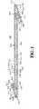
- FIG. 1illustrates an embodiment of the invention wherein the main stent component is formed as a patterned band, shown in an uncoiled state, i.e., flat.
- the pattern of the ribboncomprises a single row of cells 430, defined by an interconnected first side band 401 with undulations and a second side band 402 with undulations.
- end bands 406 and 407extend at an oblique angle to side bands 401 and 402.
- the row of cells 430take on a continuous helical winding along the central portion of the longitudinal axis of the stent while end bands 406 and 407 form a right cylindrical shape at each end of the stent.
- the formation of the tubular helical central body portion from a flat patterned band in this manneris distinguished from the process where the design is formed from a pre-existing tubular material.
- the first side band 401 and second side band 402extend in a generally parallel orientation except at either end of the side bands where the first side band tapers toward the second side band and the second side band tapers toward the first side band.
- the undulating pattern of the first side band 401comprises troughs (e.g., 410, 411) that extend toward the second side band 402 and peaks ( e.g., 414, 415) that point away from the second side band 402.
- the undulations of the second side band 402comprise troughs (e.g., 412, 413) that extend toward the first side band 401 and peaks (e.g., 416, 417) that point away from the first side band 401.
- the first and second side bandsare oriented out-of-phase with each other (troughs substantially aligned with troughs).
- the first and second side bandsmay be in-phase so that the peaks and troughs are substantially aligned.
- the struts of the side bands defining peaks (416, 417) and troughs (412, 413)have substantially equal lengths in the central strip portion but become shorter as the side bands taper toward each other.
- the first side band 401 and second side band 402are connected to each other by a plurality of first cross-struts 403, defining a row of cells.
- at least one trough (e.g., 411) of the first side band 401is connected to a corresponding trough ( e.g., 413) of the second side band 402 via a first cross strut 403 in FIG. 1 .
- a series of cellsare formed, each cell 430 defined individually by the joining of the adjacent side bands to form an enclosed space by cross-struts.
- a cell in the central strip portionis defined by the portion of the first side band between troughs 410 and 411, the portion of the second side band between troughs 412 and 413 and first cross-struts 403 respectively connecting troughs 410 and 412 and troughs 411 and 413.
- first cross-struts 403may differ from that illustrated in FIG. 1 .
- the first cross-struts 403may connect the first band 401 and second band 402 at regular intervals at, inter alia, every trough, every second trough, every third trough, or every fourth trough, etc., thereby making larger cells or cells with different geometric properties.
- cross-strutsmay be omitted and the first side band may be connected directed to the second side band.
- cell 449is diamond shaped and defined only by the undulations of the first and second side bands.
- first cross-struts 403may connect the first side band 401 and second side band 402 at varying, non-regular intervals.
- Variable, non-regular interval connectionsmay form a variety of differently sized cells along a continuous main stent component as may be appropriate for a particular use.
- the cross-strutsmay connect the peaks of the first side band to the trough of the second side band, or the troughs of the first side band to the peaks of the second side band.
- the first cross-struts 403may each have the same width relative to each other and to the side bands 401, 402, as shown in FIG. 1 .
- the first cross-struts 403may have a different width from the first and second side bands 401, 402, or a different width from each other, as appropriate for a particular use.
- the cross-strutsmay connect adjacent or offset troughs of the first and second side bands 401, 402.
- first cross-struts 403may comprise a straight member or may contain one or more loops. As shown in FIG.
- differently shaped cross-struts, or no cross-strutsmay alternatively be employed in a single stent design depending on the particular use of the stent so that a stent having different cell shapes may be formed.
- Exemplary cell shapesare described in U.S. Patent No. 7,141,062 (triangular cells) or 5,733,303 (square cells); the disclosure of square and triangular cell structures is incorporated from these patents by reference herein.
- Square cellshave four points of connection as between radially supporting elements while a triangular cell has three points of connection between radially supporting elements.
- the undulations of the side and end bandsprovide the radially supporting elements of the invention.
- the side bands 401 and 402 of the main stent component 400 in the embodiment depicted in FIG. 1taper at each end.
- the length of the cross-struts 403shorten toward each end of the main stent component 400, so that the first and second side bands 401, 402 become more snugly arranged and eventually are connected directly at points of connection 404 and 405.
- the side bandsmay taper to one another by reducing the strut lengths in the undulations.
- a first end band 406extends from the end of the first side band 401 in a direction offset and oblique from the general direction of the first side band 401.
- the first end bandextends back in the direction of the first side band at an angle less than 45 degrees to the direction of the first side band when the strip is laid flat.
- a second end band 407extends from the end of the second side band 402 in a general direction offset and oblique from the general direction of the second side band 402 and opposite the first end band.
- the second end bandalso extends back in the direction of the second side band at an angle less than 45 degrees to the direction of the second side band when the strip is laid flat.
- end bands 406 and 407are configured to form right cylinders at the ends of the stent, and flank both ends of the helical winding of the strip.
- First end band 406has first edge 450 and second edge 451. In the tubular form, first edge 450 is brought together with second edge 451 to form a right cylinder to the longitudinal axis of the stent.
- Second end band 403has first edge 452 and second edge 453.
- first edge 452is brought together with second edge 453 for form a right cylinder to the longitudinal axis of the stent.
- edge 450 and 451may be permanently connected, or as an alternative, may be held in position with a securement, which may hold the two edges in close proximity to form a right cylinder to the longitudinal axis of the stent.
- the first end band 406 and second end band 407each contain undulations having struts and loops or turns.
- the first end band 406has troughs (e.g., 418, 419) that extend toward the first side band 401 and peaks ( e.g., 422, 423) that point away from the first side band 401.
- the second end band 407has troughs ( e.g., 420, 421) that extend toward the second side band and peaks ( e.g., 424, 425) that point away from the second side band 402.
- the first end band 406connects directly to the first side band 401 at, e.g., trough 418; however, as the first end band 406 angularly extends away from the first side band, second cross-struts 426 connect the first end band 406 to the first side band 401.
- the second end band 407connects directly to the second side band 402 at, e.g., trough 420; however, as the second end band 407 angularly extends away from the second side band, second cross-struts 426 connect the second end band 407 to the second side band 402.
- the second cross-struts 426may contain one or more loops between points of connection with adjacent end bands and/or side bands.
- the peaks of the first end band 406 and second end band 407optionally may have additional circular structures extending from the peaks ( e.g., 423, 424) as depicted by FIG. 1 .
- a third end band 408 having undulationsis arranged generally parallel to first end band 406, with the troughs of the third end band, e.g., 427, extending toward the first end band and directly connected to said first end band.
- a fourth end band 409 having undulationsis arranged generally parallel to second end band 407, with the troughs of the fourth end band, e.g. 428, extending toward the second end band.
- FIG. 2illustrates the main stent component 400 of FIG. 1 helically wound into a tubular structure.
- the strip of cells 430 in main stent component 400forms a helical winding in the central portion in which a cell in one winding is longitudinally-spaced apart from the cell of an adjacent winding.
- First side band 401 and second side band 402are connected by cross-struts 403 and are helically wound around the longitudinal axis of the stent so that first and second side bands alternate along the stent's longitudinal axis.
- FIG. 2illustrates the main stent component 400 of FIG. 1 helically wound into a tubular structure.
- the strip of cells 430 in main stent component 400forms a helical winding in the central portion in which a cell in one winding is longitudinally-spaced apart from the cell of an adjacent winding.
- First side band 401 and second side band 402are connected by cross-struts 403 and are helically wound around
- first side band 401is adjacent and connected to adjacent second side band 402 by cross strut 403, but is also adjacent and unconnected to the second side band of an adjacent winding 402".
- second side band 402is unconnected to a longitudinally adjacent first side band 401' in the helical stent.
- End bands 406 and 407secure the ends of the tubular structure and form substantial right cylindrical rings relative to the longitudinal axis of the stent. Open spaces, e.g., 431 and 432, exists between adjacent windings, e.g., 433, 434, 435.
- Open spacese.g., 431 and 432, exists between adjacent windings, e.g., 433, 434, 435.
- the first and second side bands 401 and 402are spaced apart either by the presence of the cross-struts, or by the spaced winding of the helical strip.
- a securementas discussed below, may maintain the spacing between the adjacent windings.
- FIG. 3illustrates a stent according to another embodiment of the invention wherein the helical windings are positioned so that little or no substantial longitudinal space exists between cycles of the helical coils. That is, as illustrated by FIG. 3 , the peaks (e.g. 414, 415) of the first helical winding 460 are nestled toward troughs (e.g. 412, 413) of the second helical winding 461; yet, the first side band 401 remains substantially parallel to the second side band 402. Likewise, the peaks ( e.g. 416, 417) of the second helical winding 461 are nestled toward troughs (e.g. 410, 411) of the first helical winding 460.
- the peaks (e.g. 414, 415) of the first helical winding 460are nestled toward troughs (e.g. 412, 413) of the second helical winding 461; yet, the first side band 401 remains substantially parallel to the second side
- first side band 401 and the second side band 402are arranged so that the substantially similar but opposite undulations are aligned, the first side band 401 and the second side band 402 can approach one another in this fashion over the entire length of the formed stent.
- Side bands having struts of identical lengthsalso aid in nestling. In this manner, the first side band 401 and the second side band 402 may be described as nestled to one another. In FIG. 3 , the first and second side bands 401 and 402 are spaced apart only by the presence of the cross-struts.
- the distance between the nestled windingsis shorter than the length of cross-strut 403.
- the first side bandis nestled toward helically adjacent second side band without direct connection between the first side band and adjacent second side band.
- the stent of FIG. 3has the additional advantage that the nestling of adjacent windings minimizes the unsupported areas of the vessel wall and/or securement to prevent sagging of the securement into the lumen upon expansion without any loss of flexibility to the stent, as further discussed below.
- the nestling of the helical coilsseparately may facilitate the maintenance of the structure in the tubular form.
- FIG. 4illustrates an alternative embodiment wherein the main stent component 1300 is laid out in flat form, i.e., uncoiled. As depicted, the main stent component 1300 has a patterned band in the longitudinal direction. Like the embodiment of FIG. 1 , the design of the main stent component 1300 in FIG. 4 contains a first side band 1301, a second side band 1302, a first end band 1306, a second end band 1307, a third end band 1308 and a fourth end band 1309.
- side bands 1301 and 1302form a continuous helical winding for the central portion of the stent body while first and second end bands 1306 and 1307 form right cylinders to the longitudinal axis of the stent for the end rings of the stent.
- first edge 1350is brought together with second edge 1351 while, in the second end band, first edge 1352 is brought together with second edge 1353.
- Main stent component 1300comprises struts having one or more fenestrations into which a therapeutic substance may be deposited.
- Each bandis formed with struts of sufficient width to include one or more fenestrations as shown, for example, in FIG. 4 .
- the fenestrated struts of main stent component 1300may be of any geometric shape, including, but not limited to, round, oval or rectangular. Further, the fenestrations may extend through the entire thickness of the strut (full fenestrations), or may extend only partially through (partial fenestrations), being open only on one side of the strut (luminal or abluminal in the tubular form). Also, the stent may have struts containing fenestrations having variable sizes, numbers and shapes on one strut or between different struts.
- the inventioncontemplates struts having full and/or partial fenestrations on either or both of the side and/or end bands.
- the struts defining the peaks and troughs of the side bandsmay vary in length along the length of the main stent component to accommodate the desired shape for the resulting helically coiled stent structure and the number of fenestrations.
- side band struts 1358 and 1359differ in length as do end band struts 1356 and 1357.
- the fenestrated strutsare connected by loops or turns 1370 wherein the material is narrower than that of the fenestrated struts to provide enhanced flexibility.
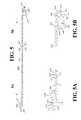
- FIG. 5illustrates yet another embodiment of the invention where the main stent component 1200 is laid out in flat form, i.e., uncoiled.
- the main stent component 1200is a single side band 1201 in the longitudinal direction when laid flat.
- Side band 1201is attached to first end band 1202 and second end band 1203 by cross-struts 1240 and 1241, respectively.
- Side band 1201comprises an alternating pattern of peaks (e.g., 1210, 1212) and troughs ( e.g., 1211, 1213) defined by struts having the same or variable lengths.
- Each side and end bandis formed with struts having sufficient width to include one or more full or partial fenestrations, as described above for FIG.
- the fenestrated strutsare connected by loops or turns 1270 that are narrower than that of the fenestrated struts to provide enhanced flexibility.
- the strutsare of varying length and vary in the number of fenestrations in each strut.
- strut 1217has a different length and number of fenestrations than strut 1215.
- Strut 1216has a different length but the same number of fenestrations than strut 1215.
- struts 1214 and 1215have the same lengths and number of fenestrations.
- the stent of FIG. 5Acontemplates that struts ( e.g., 1217) near the ends of the first side band 1201 may have different lengths than struts 1214 and 1215 and are configured to aid in helical winding.
- End bands 1202 and 1203form circumferential end rings upon rolling of the structure into a stent.
- the first end band 1202 and second end band 1203extend from the ends of the side band 1201 in a direction angularly offset from the general direction of the side band 1201.
- End bands 1202 and 1203are configured to form right cylinders at the ends of the stent, flanking the helical windings of the central stent body upon winding of the structure into a stent.
- First end band 1202has first edge 1250 and second edge 1251. In the tubular form, first edge 1250 is brought together with second edge 1251 to form a right cylinder to the longitudinal axis of the stent.
- Second end band 1203has first edge 1252 and second edge 1253.
- first edge 1252is brought together with second edge 1253 to form a right cylinder to the longitudinal axis of the stent.
- the edges (1250 and 1251; 1252 and 1253)may be permanently affixed, or as an alternative, may be held in position with a securement which may keep the two edges in close proximity to maintain a right cylinder to the longitudinal axis of the stent.
- first end band 1202comprises a band of undulations.
- the direction of the first end band 1202is offset at an angle to the direction of the side band 1201.
- the first end band extends from the side bandis at an angle less than 45 degrees to the central body of the stent when the stent is laid flat.
- the undulating pattern of the first end band 1202comprises alternating peaks ( e.g., 1219, 1221) and troughs ( e.g., 1220, 1222). Troughs (1220, 1222) of the first end band extend in the direction of the side band while the peaks (1219, 1221) point away from the side band.
- First end band 1202also may contain struts having fenestrations.
- cross-links 1240 and 1242connect the side band to the first end band.
- Cross-links 1240 and 1242extend from the troughs of the first end band to the peak of the side band.
- Cross-links extending between the side band and the first end bandare flexible connectors having one or more curved portions.
- the inventionalso contemplates an embodiment where the cross-links may contain one or more loops.
- second end band 1203also comprises a band of undulations.
- the direction of the second end band 1203is angularly offset to the direction of the side band 1201.
- the second end bandextends from the side band at an angle less than 45 degrees to the central body of the stent when the stent is laid flat.
- the undulating pattern of the second end band 1203comprises alternating peaks ( e.g., 1223, 1225) and troughs ( e.g., 1224, 1226). Troughs (1224, 1226) of the second end band extend in the direction of the side band while the peaks (1223, 1225) point away from the side band.
- Second end band 1203contains struts having fenestrations.
- cross-link 1241connects the side band to the second end band.
- Cross-link 1241extends from the trough of the second end band to the trough of the side band.
- Cross-links extending between the side band and second end bandare flexible connectors having one or more curved portions.
- Cross-links connecting the side band to the second end bandmay comprise at least one loop.
- the inventioncontemplates other end bands similar in construction to first and second end bands and connected to either the first or second end bands to facilitate helical winding and uniform coverage.
- a third end band 1204 having fenestrated strutsis connected to the second end band by cross-link 1243.
- the inventioncontemplates first and second end bands which are not identically connected to the undulating or patterned side bands and which are not identical to each other.
- any one or all the end bandsmay comprise struts sufficiently wide to accommodate one or more full or partial fenestrations which are connected together with loops having a narrower gauge than the fenestrated struts.
- the main stent componentmay be held in a helically wound position by a second component, securing the helical windings into a tubular structure.
- the second componentreferred to herein as a securement
- the securementmaintains the helical winding of the central stent body and/or the formation of right cylinders by the end bands.
- the securementcomprises a structure in the form of fibers, sheets, threads or ribbons which are wrapped around or itself embedded in the coiled main stent component.
- wires or ribbons formed of a metal or non-metal materialmaintain the main stent component in its tubular configuration.
- the securementcomprises a material that allows flexibility and expansion of the helical main stent component without tearing or detachment of the securement and allows movement between the coiled windings of the main stent body relative to each other.
- a materialmay be applied to a tubular stent in a continuous or non-continuous manner depending upon the particular needs of the structure contemplated.
- the securementallows expansion of the stent and maximal bending during and after implantation without reaching the elastic limit.
- the elastic rangemay be a product either of inherent elasticity in the material used, such as with certain polymers, or of the inclusion of a reserve length of a non-elastic material between points of connection with the main stent component.
- Yet another advantage of a securementis the prevention of "stent jail” phenomenon, or the complication of tracking into side branches covered by the stent.
- a further advantageis the high fatigue resistance of particular securement structures with high elastic range.
- the securementis a polymer that is a biocompatible material.
- Biocompatible materialmay be durable, such as polyesters, polyanhydrides, polyethylenes, polyorthoesters, polyphosphazenes, polyurethane, polycarbonate urethane, silicones, polyolefins, polyamides, polycaprolactams, polyimides, polyvinyl alcohols, acrylic polymers and copolymers, polyethers, celluiosics and any of their combinations in blends or as copolymers.
- Of particular usemay be silicone backbone-modified polycarbonate urethane and/or expanded polytetrafluoroethylene (ePTFE).
- Any polymer having a high elastic ratio (high elongation factor within the elastic range)is particularly suitable for a securement.
- the polymermay also be porous.
- the polymermay also be used as a matrix for eluting drug thereby providing a uniform elution bed. This type of porous securement may be applied to any other stent structure.
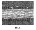
- FIG. 6shows the coiled main stent component 600 of FIG. 4 , described above, wherein a porous and durable polymer securement 601 is applied over main stent component 600.
- Two adjacent struts of a first side bandare connected to one another by turn 602, which includes a "dimple".
- the inclusion of a dimple in the turnsis an optional feature depending upon the desired properties of the resulting stent.
- FIG. 6also illustrates turn 603 which is without a dimple, and is employed in this embodiment at points where cross-struts connect the first side band to the second side band.
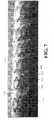
- the helical main stent component 500is secured by embedding the tubular structure in a polymer sheet 701 and illustrates one coiled form of the main stent component depicted in FIG. 2 , that is, one where the adjacent helical coils of the stent are spaced apart but the stent maintains its helical structure through the embedded polymer securement.
- the securementmay be disposed within interstices and/or embedded throughout the stent.
- a polymer sheetmay secure portions of the stent structure or may fully envelop the entire stent to hold the central portion in the helical form and the end bands in the cylindrical form.
- Polymeric securements as described abovemay also be employed in the form of threads, wires or ribbons, thereby securing the main stent component through, for example, a series of points of connection with the main stent component.
- One or more securement threads, wires or ribbonsmay be coiled around the stent in a helically different direction than the main stent component.
- the thread, wire or ribbonmay be coiled around the stent in the reverse helical orientation from the direction of the helically wound strip.
- securementsmay be arranged along a longitudinal axis of the stent.
- each thread, wire or ribbonmay overlap with the main stent component in a regular pattern across the length of the stent and may effectively function to secure the helical stent body structure.
- the securement thread, wire or ribbonmay be affixed to the main stent component at one or more points of overlap through a variety of means, e . g., welding, bonding, embedding, braiding, weaving, crimping, tying, press-fitting or the like, including also joining by adhesive means, e.g., gluing, dip coating, spray coating or the like.
- the polymeric securementmay also be injected into a mold with or without the stent and hence become integrated within the stent.
- the threads, wires or ribbonsmaintain the tubular shape of the stent, while the longitudinally flexible quality of the polymeric material discussed above will enhance the overall flexibility of the stent.
- FIG. 8illustrates a helically coiled stent wherein the main stent component 800 forms a helically wound tubular structure that is secured in place by two ribbons 801.
- the ribbons 801are a polymeric material that extend along the length of the stent.
- the ribbonsmay be affixed to the outside or the inside surface of the stent, or may be embedded in the helically coiled main stent component.
- the main stent component 800is embedded within each ribbon 801 1 at points where the main stent component 800 and each second component ribbon 801 intersect.
- FIGS. 9illustrate a helically coiled stent wherein the main stent component 1000 forms a tubular structure similar to FIG. 2 and one or more securement wires 1001 are coiled in a different helical direction to that of the coiled central body portion of the stent.
- the securement wires 1001are affixed to the main stent component 1000 at various points of connection 1002 along the stent, thereby maintaining the helical, tubular structure.
- any other suitable materialincluding metals and/or non-metals, may be employed as securements in the form of threads, wires or ribbons to secure the main stent component.
- the metal or non-metal securement wire, thread or ribbonmay be affixed to the main stent component where they overlap through one or more of a variety of means as identified above. If the material employed to manufacture the second component is of a lesser longitudinal flexibility than desired, increased flexibility may be achieved by increasing the length of the thread, wire or ribbon between points of connection, thereby providing reserve length of the second component that can extend upon expansion or bending of the stent.
- the main stent componentis an amorphous metal alloy
- further advantagesmay be provided, i.e., enhanced corrosion resistance, resistance to unwanted permanent deformation and/or higher strength for a given metal thickness.
- Stents of the inventioncomprising amorphous metal alloys may also exhibit significantly lower conductance or are non-conductive, compared to their crystalline or polycrystalline counterparts. Such alloys may provide improved tensile strength, elastic deformation properties, and reduced corrosion potential to the devices. These may be important features in medical devices to provide an extended fatigue-resistant lifespan for devices that are subjected to repeated deformations and fatigue in the body. In addition, these features allow production of smaller or thinner devices that are as strong as their bulkier conventional counterparts.
- the amorphous metal alloy of the main stent componentmay be a metalloid, non-limiting examples of which include silicon, boron, and phosphorus.
- Another possible amorphous metal alloyis a Fe-Cr-B-P alloy.
- Many other similar alloysare suitable and known to one of ordinary skill in the art.
- One embodiment of this inventioncontemplates intraluminal prosthetic devices comprising at least one amorphous metal alloy combined with components made of other materials, limited only by the biocompatibility of the materials.
- This embodiment of the inventionmay contain one or more amorphous metal alloys.
- the devicemay have components constructed of stainless steel, cobalt chromium ("CoCr"), NiTi or other known materials. The details of these alloys, which have certain advantages, are disclosed in U.S. Patent Nos. 5,836,964 and 5,997,703 , which are hereby expressly incorporated by reference.
- Amorphous metal stents of the inventionmay be formed of one or more flat strips of helically wound metal. Because amorphous metal alloys cannot be easily welded without the metal reverting to an undesirable crystalline form, the present invention contemplates a securement for the helically wound amorphous metal alloy main stent component, further described below.
- the method of combining or joining the amorphous metal alloy to the securementscan be achieved using particular methods known in the art.
- a biocompatible polymer securement covering all or part of the amorphous metal main stent componentmay be used to secure the helical windings in its tubular shape for positioning and expansion in the lumen as well as the end bands in a cylindrical shape.
- Other non-limiting examples of securement methodsinclude physical joining (e.g., braiding, weaving, crimping, tying, and press-fitting) and joining by adhesive methods (e.g., gluing, dip coating, and spray coating). Combinations of these methods are also contemplated by this invention.
- any or all of the securement or main stent componentmay be embedded with a therapeutic agent that will inhibit or decrease cell proliferation or will reduce restenosis.
- the main stent componentmay comprise at least one fenestration where the drug is deposited.
- Non-limiting examples of such drugsinclude for example sirolimus, rapamycin, everolimus and paclitaxol, and analogs of these.
- the stentmay be treated to have active or passive surface components such as agents that will be advantageous for a longer time after the stent is embedded in the vessel wall.
- the stent of the present inventionmay be balloon expandable or self-expanding as is known in the art.
- a balloon-expandable stent systemis used to deliver the stent, the stent is mounted on the balloon and the catheter assembly is positioned at the implantation site. The balloon is then inflated, radially applying a force inside the stent and the stent is expanded to its expanded diameter.
- the stentmay be self-expanding in which case a balloon is not needed to facilitate expansion and delivery of the stent.
Landscapes
- Health & Medical Sciences (AREA)
- Life Sciences & Earth Sciences (AREA)
- General Health & Medical Sciences (AREA)
- Veterinary Medicine (AREA)
- Public Health (AREA)
- Animal Behavior & Ethology (AREA)
- Engineering & Computer Science (AREA)
- Biomedical Technology (AREA)
- Heart & Thoracic Surgery (AREA)
- Vascular Medicine (AREA)
- Epidemiology (AREA)
- Oral & Maxillofacial Surgery (AREA)
- Cardiology (AREA)
- Transplantation (AREA)
- Surgery (AREA)
- Chemical & Material Sciences (AREA)
- Medicinal Chemistry (AREA)
- Physics & Mathematics (AREA)
- Optics & Photonics (AREA)
- Chemical Kinetics & Catalysis (AREA)
- Inorganic Chemistry (AREA)
- Molecular Biology (AREA)
- Dispersion Chemistry (AREA)
- Pharmacology & Pharmacy (AREA)
- Gastroenterology & Hepatology (AREA)
- Pulmonology (AREA)
- Media Introduction/Drainage Providing Device (AREA)
- Prostheses (AREA)
- Materials For Medical Uses (AREA)
- Polymers & Plastics (AREA)
- Organic Chemistry (AREA)
Abstract
Description
- This application claims the benefit of
U.S. Application Serial no. 12/428,347, filed on April 22, 2009 - The invention relates generally to stents, which are intraluminal endoprosthesis devices implanted into vessels within the body, such as blood vessels, to support and hold open the vessels, or to secure and support other endoprostheses in vessels.
- Various stents are known in the art. Typically, stents are generally tubular in shape, and are expandable from a relatively small, unexpanded diameter to a larger, expanded diameter. For implantation, the stent is typically mounted on the end of a catheter with the stent being held on the catheter in its relatively small, unexpanded diameter. Using a catheter, the unexpanded stent is directed through the lumen to the intended implantation site. Once the stent is at the intended implantation site, it is expanded, typically either by a balloon or by allowing the stent to self-expand. In either case, the expanded stent resists the tendency of the vessel to narrow, thereby maintaining the vessel's patency.
- Stents may be constructed from tubes or from a flat sheet of metal, which is rolled and fixed such as by welding, mechanical lock or otherwise, to form the tubular structure of the stent.
- Some examples of patents relating to stent designs include
U.S. Patent No. 4,733,665 to Palmaz ;U.S. Patent No. 4,800,882 and5,282,824 to Gianturco ;U.S. Patent Nos. 4,856,516 and5,116,365 to Hillstead ;U.S. Patent Nos. 4,886,062 and4,969,458 to Wiktor ;U.S. Patent No. 5,019,090 to Pinchuk ;U.S. Patent No. 5,102,417 to Palmaz and Schatz ;U.S. Patent No. 5,104,404 to Wolff ;U.S. Patent No. 5,161,547 to Tower ;U.S. Patent No. 5,383,892 to Cardon et al. ;U.S. Patent No. 5,449,373 to Pinchasik et al. ; andU.S. Patent No. 5,733,303 to Israel et al. - One type of stent is known as the helical or coiled stent. Such stent designs are described in, for example,
U.S. Patent Nos. 6,503,270 and6,355,059 , incorporated herein,in toto, by reference. This stent design is configured as a helical stent in which the coil is formed from a wound strip of cells wherein the cells form a serpentine pattern comprising a series of bends. Other similar helically coiled stent structures are known in the art. - Prior stent designs have focused on providing sufficient radial strength when it is expanded so that it can sufficiently support the lumen. Stents with high radial strength, however, tend also to be more longitudinally stiff than the vessel in which it is implanted. When the stent is more longitudinally stiff than the vessel in which it is implanted, increased trauma to the vessel may occur at the ends of the stent, due to stress concentrations on account of the mismatch in compliance between the stented and un-stented sections of the vessel, or otherwise. In addition, the stent may interfere with the vessel's natural tendency to bend and to stretch. Conversely, stents with good flexibility often lack sufficient and/or uniform radial support for the vessel wall. Thus, a continued need exists in the art for a stent having a balance of good radial strength and a high degree of longitudinal flexibility.
- Another problem in the art arises when trying to simplify the manufacturing process of a stent to reduce costs yet prevent manufacturing defects, while still producing a stent with uniformly high flexibility and sufficient radial support.
- The present invention provides a helical stent for intravascular use that is longitudinally flexible such that it can easily be tracked down a tortuous lumen while conforming to the contours of the vessel and provide uniform support to the vessel after deployment. The stent of the invention comprises a main stent component and a second stent component. The main stent component may be of a metal or amorphous metal alloy material. With an amorphous metal stent, the stent has the radial support of a conventional metal stent combined with longitudinal flexibility, conformability and fatigue resistance to repeated longitudinal bending, compression and twisting which may be higher than that achievable by metal stents.
- Upon formation into a stent, the main stent component forms a tubular structure of helical windings at an oblique angle to the longitudinal axis of the stent. The helical windings extend at least along the central portion of the stent. Each winding may be spaced apart from the adjacent winding, or may be nestled in the adjacent winding. The distance along the longitudinal axis of the stent between the windings may be varied depending on the needs of the particular stent. Before it is helically wound to form a tubular stent, the main stent component is a flat ribbon or strip, which is defined by undulations (e.g., sinusoidal, zig-zag) or a patterned band of cells (e.g., hexagonal or other like-geometric structure). The strip is composed of one or more side bands that wind helically along the length of the stent, as well as end bands extending from either or both ends of the side bands, positioned at an angle to the side bands. The end bands are configured to form a right cylinder to the longitudinal axis of the stent at either or both ends of the formed stent. The side bands and end bands are understood to include portions having, for example, a generally sinusoidal, zig-zag, hexagonal or other like geometric structure.
- In one embodiment of the invention, the main stent component may have one or more struts, which are sufficiently wide to include one or more full or partial fenestrations. The fenestrated struts may be connected by loops or turns whose width is narrower than that of the fenestrated struts to provide enhanced flexibility in the loops or turns.
- In another embodiment, the main stent component may be designed such that each helical winding is nestled next to an adjacent helical winding of the helical structure so that the space between the windings is minimized; that is, one winding is nestled into an adjacent, substantially similar winding as the side band ribbon travels diagonally around the circumference of the stent. In this manner, the helical windings of the stent provide enhanced coverage of the wall of the lumen without loss of overall stent flexibility. Because the helical windings may be nestled into one another without directly touching each other, the overall flexibility of the formed stent is unaffected by the proximity of adjacent windings of the helical coils.
- The second stent component,i.e., a securement, functions to maintain the tubular shape of the main stent component while aiding in longitudinal flexibility. The securement provides structural support to the stent. The securement is oriented and affixed to the main stent component such that, upon expansion or bending of the stent, the securement contributes to the overall flexibility of the stent while still maintaining the main stent component in a tubular shape. The securement may comprise fibers, wires, threads, ribbons, strips, polymers, meshes or the like.
Figure 1 illustrates a main stent component composed of a flat ribbon with a patterned band according to one embodiment of the invention.Figure 2 illustrates a main stent component of a patterned band formed into a tubular shape having a space between adjacent helical windings.Figure 3 illustrate another embodiment wherein a helical winding of the main stent component is nestled into an adjacent helical winding.Figure 4 illustrates an embodiment of a main stent component composed of a flat ribbon having a patterned band and comprises struts with one or more exemplary fenestrations.Figure 4A is an enlarged view of an end band of the main stent component ofFigure 4 .Figure 5 illustrates a main stent component composed of a flat ribbon having undulations and comprising struts with one or more exemplary fenestrations.Figure 5A is an enlarged view of a first end band of the flat ribbon ofFigure 5 .Figure 5B is an enlarged view of a second end band of the flat ribbon ofFigure 5 .Figure 6 illustrates a photograph of a securement structure and a main stent component.Figure 7 illustrates an embodiment of a helical main stent component with a patterned band and embedded in a securement.Figure 8 illustrates an embodiment of the helical main stent component embedded in several ribbon securements.Figure 9 illustrates a helical main stent component maintained by a plurality of helical securements fastened at discrete points.- This invention provides a new class of intraluminal prosthetic devices defined as helical hybrid stents. As further explained below, the stents of the invention comprise a main stent component in the form of a helical tubular structure, which may be held in the tubular shape by a second stent component,i.e., a securement. The main stent component is formed from a continuous undulating or patterned strip helically wound to form a helical stent. The strip has end sections that form cylindrical rings in the tubular helical stent. As such, one inventive feature is the central body of the stent having a spiral structure which is flanked by cylindrical rings at both ends of the stent. The strip forming the central body portion comprises one or more side bands each having undulations while the ends sections comprise one or more end bands each having undulations. Each end band is connected to a side band at an angle offset to the side band and may extend back toward the side band. The lengths of struts forming the undulations of the side or end bands may be uniform or variable to assist in the helical winding. The side and end bands may be connected to one another by cross-struts. The length and shape of the cross-struts may be varied across the length of the strip, and the cross-strut may contain one or more loops. The undulations of the helically wound stent may be nestled next to an adjacent helical undulation to promote uniform coverage. The main stent component may be formed of any conventional metallic substance or an amorphous metal alloy.
- In any of the novel helical stents herein, the main stent component may also include struts having full or partial fenestrations of any suitable shape and size in the side and/or end bands. Fenestrations allow the deposit of a therapeutic agent with clinical benefits within the recesses of the helical stent. The stent may be configured with struts of sufficient width to accommodate the fenestrations and loops connecting the struts of sufficiently narrow dimensions to accommodate bending and expansion of the resulting stent.
- The main stent component, with or without fenestrations or nestling, may be held in place by another inventive feature,i.e., the securement. The securement may comprise any form of polymer, fibers, wires, threads, bands, ribbons, meshes or sheets affixed to the main stent component by any of a variety of means known in the art, such as, for example, welding, bonding, embedding, braiding, weaving, crimping, tying, press-fitting or injection into a mold with the main stent component, also including joining by adhesive means,e.g., gluing, dip coating, spray coating, or the like. The securement may be oriented circumferentially, helically, longitudinally or otherwise and may be affixed to or embedded in a portion or the entirety of the main stent component such that, upon expansion or bending of the stent, the securement facilitates the overall flexibility of the stent while still maintaining the main stent component in a tubular shape.
- The main stent component may be formed and patterned from a strip using methods known in the art or described herein.
FIG. 1 illustrates an embodiment of the invention wherein the main stent component is formed as a patterned band, shown in an uncoiled state,i.e., flat. As depicted inFIG. 1 , the pattern of the ribbon comprises a single row ofcells 430, defined by an interconnectedfirst side band 401 with undulations and asecond side band 402 with undulations. Also, endbands bands cells 430 take on a continuous helical winding along the central portion of the longitudinal axis of the stent whileend bands - In
FIG. 1 , thefirst side band 401 andsecond side band 402 extend in a generally parallel orientation except at either end of the side bands where the first side band tapers toward the second side band and the second side band tapers toward the first side band. As depicted inFIG. 1 , the undulating pattern of thefirst side band 401 comprises troughs (e.g., 410, 411) that extend toward thesecond side band 402 and peaks (e.g., 414, 415) that point away from thesecond side band 402. Similarly, the undulations of thesecond side band 402 comprise troughs (e.g., 412, 413) that extend toward thefirst side band 401 and peaks (e.g., 416, 417) that point away from thefirst side band 401. Thus, inFIG. 1 , the first and second side bands are oriented out-of-phase with each other (troughs substantially aligned with troughs). In other embodiments, the first and second side bands may be in-phase so that the peaks and troughs are substantially aligned. - In
FIG. 1 , the struts of the side bands defining peaks (416, 417) and troughs (412, 413) have substantially equal lengths in the central strip portion but become shorter as the side bands taper toward each other. In the embodiment ofFIG. 1 , thefirst side band 401 andsecond side band 402 are connected to each other by a plurality offirst cross-struts 403, defining a row of cells. Specifically, at least one trough (e.g., 411) of thefirst side band 401 is connected to a corresponding trough (e.g., 413) of thesecond side band 402 via afirst cross strut 403 inFIG. 1 . Thus, in this embodiment, a series of cells are formed, eachcell 430 defined individually by the joining of the adjacent side bands to form an enclosed space by cross-struts. For example, a cell in the central strip portion is defined by the portion of the first side band betweentroughs troughs first cross-struts 403 respectively connectingtroughs troughs - In alternative embodiments, the number, length and shape of
first cross-struts 403 may differ from that illustrated inFIG. 1 . For example, thefirst cross-struts 403 may connect thefirst band 401 andsecond band 402 at regular intervals at,inter alia, every trough, every second trough, every third trough, or every fourth trough, etc., thereby making larger cells or cells with different geometric properties. Also, cross-struts may be omitted and the first side band may be connected directed to the second side band. For example,cell 449 is diamond shaped and defined only by the undulations of the first and second side bands. In other embodiments, thefirst cross-struts 403 may connect thefirst side band 401 andsecond side band 402 at varying, non-regular intervals. Variable, non-regular interval connections may form a variety of differently sized cells along a continuous main stent component as may be appropriate for a particular use. Further, the cross-struts may connect the peaks of the first side band to the trough of the second side band, or the troughs of the first side band to the peaks of the second side band. - The
first cross-struts 403 may each have the same width relative to each other and to theside bands FIG. 1 . Alternatively, thefirst cross-struts 403 may have a different width from the first andsecond side bands second side bands first cross-struts 403 may comprise a straight member or may contain one or more loops. As shown inFIG. 1 , differently shaped cross-struts, or no cross-struts may alternatively be employed in a single stent design depending on the particular use of the stent so that a stent having different cell shapes may be formed. Exemplary cell shapes are described inU.S. Patent No. 7,141,062 (triangular cells) or5,733,303 (square cells); the disclosure of square and triangular cell structures is incorporated from these patents by reference herein. Square cells have four points of connection as between radially supporting elements while a triangular cell has three points of connection between radially supporting elements. The undulations of the side and end bands provide the radially supporting elements of the invention. - The
side bands main stent component 400 in the embodiment depicted inFIG. 1 taper at each end. The length of the cross-struts 403 shorten toward each end of themain stent component 400, so that the first andsecond side bands connection - Extending from the end of either or both
side bands FIG 1 areend bands first end band 406 extends from the end of thefirst side band 401 in a direction offset and oblique from the general direction of thefirst side band 401. InFIG. 1 , the first end band extends back in the direction of the first side band at an angle less than 45 degrees to the direction of the first side band when the strip is laid flat. Asecond end band 407 extends from the end of thesecond side band 402 in a general direction offset and oblique from the general direction of thesecond side band 402 and opposite the first end band. InFIG. 1 , the second end band also extends back in the direction of the second side band at an angle less than 45 degrees to the direction of the second side band when the strip is laid flat. When forming the tubular stent, endbands First end band 406 hasfirst edge 450 andsecond edge 451. In the tubular form,first edge 450 is brought together withsecond edge 451 to form a right cylinder to the longitudinal axis of the stent.Second end band 403 hasfirst edge 452 andsecond edge 453. In the tubular form,first edge 452 is brought together withsecond edge 453 for form a right cylinder to the longitudinal axis of the stent. As further explained below,edge - The
first end band 406 andsecond end band 407 each contain undulations having struts and loops or turns. Thefirst end band 406 has troughs (e.g., 418, 419) that extend toward thefirst side band 401 and peaks (e.g., 422, 423) that point away from thefirst side band 401. Likewise, thesecond end band 407 has troughs (e.g., 420, 421) that extend toward the second side band and peaks (e.g., 424, 425) that point away from thesecond side band 402. Thefirst end band 406 connects directly to thefirst side band 401 at,e.g., trough 418; however, as thefirst end band 406 angularly extends away from the first side band,second cross-struts 426 connect thefirst end band 406 to thefirst side band 401. Likewise, thesecond end band 407 connects directly to thesecond side band 402 at,e.g.,trough 420; however, as thesecond end band 407 angularly extends away from the second side band,second cross-struts 426 connect thesecond end band 407 to thesecond side band 402. As depicted inFIG. 1 , thesecond cross-struts 426 may contain one or more loops between points of connection with adjacent end bands and/or side bands. The peaks of thefirst end band 406 andsecond end band 407 optionally may have additional circular structures extending from the peaks (e.g., 423, 424) as depicted byFIG. 1 . - In addition, a
third end band 408 having undulations is arranged generally parallel tofirst end band 406, with the troughs of the third end band,e.g., 427, extending toward the first end band and directly connected to said first end band. Afourth end band 409 having undulations is arranged generally parallel tosecond end band 407, with the troughs of the fourth end band, e.g. 428, extending toward the second end band. FIG. 2 illustrates themain stent component 400 ofFIG. 1 helically wound into a tubular structure. The strip ofcells 430 inmain stent component 400 forms a helical winding in the central portion in which a cell in one winding is longitudinally-spaced apart from the cell of an adjacent winding.First side band 401 andsecond side band 402 are connected bycross-struts 403 and are helically wound around the longitudinal axis of the stent so that first and second side bands alternate along the stent's longitudinal axis. In the helically wound stent, as shown inFIG. 2 ,first side band 401 is adjacent and connected to adjacentsecond side band 402 bycross strut 403, but is also adjacent and unconnected to the second side band of an adjacent winding 402". Similarly,second side band 402 is unconnected to a longitudinally adjacent first side band 401' in the helical stent.End bands FIG. 2 , the first andsecond side bands FIG. 3 illustrates a stent according to another embodiment of the invention wherein the helical windings are positioned so that little or no substantial longitudinal space exists between cycles of the helical coils. That is, as illustrated byFIG. 3 , the peaks (e.g. 414, 415) of the first helical winding 460 are nestled toward troughs (e.g. 412, 413) of the second helical winding 461; yet, thefirst side band 401 remains substantially parallel to thesecond side band 402. Likewise, the peaks (e.g. 416, 417) of the second helical winding 461 are nestled toward troughs (e.g. 410, 411) of the first helical winding 460. It may be desirable to position the nestled side bands so that no direct contact occurs betweenfirst side band 401 andsecond side band 402. Because thefirst side band 401 and thesecond side band 402 are arranged so that the substantially similar but opposite undulations are aligned, thefirst side band 401 and thesecond side band 402 can approach one another in this fashion over the entire length of the formed stent. Side bands having struts of identical lengths also aid in nestling. In this manner, thefirst side band 401 and thesecond side band 402 may be described as nestled to one another. InFIG. 3 , the first andsecond side bands cross-strut 403. Further, the first side band is nestled toward helically adjacent second side band without direct connection between the first side band and adjacent second side band. The stent ofFIG. 3 has the additional advantage that the nestling of adjacent windings minimizes the unsupported areas of the vessel wall and/or securement to prevent sagging of the securement into the lumen upon expansion without any loss of flexibility to the stent, as further discussed below. In addition, the nestling of the helical coils separately may facilitate the maintenance of the structure in the tubular form.FIG. 4 illustrates an alternative embodiment wherein themain stent component 1300 is laid out in flat form,i.e., uncoiled. As depicted, themain stent component 1300 has a patterned band in the longitudinal direction. Like the embodiment ofFIG. 1 , the design of themain stent component 1300 inFIG. 4 contains afirst side band 1301, asecond side band 1302, afirst end band 1306, asecond end band 1307, athird end band 1308 and afourth end band 1309. In the tubular form,side bands second end bands first edge 1350 is brought together withsecond edge 1351 while, in the second end band,first edge 1352 is brought together withsecond edge 1353.Main stent component 1300 comprises struts having one or more fenestrations into which a therapeutic substance may be deposited.- Each band is formed with struts of sufficient width to include one or more fenestrations as shown, for example, in
FIG. 4 . The fenestrated struts ofmain stent component 1300 may be of any geometric shape, including, but not limited to, round, oval or rectangular. Further, the fenestrations may extend through the entire thickness of the strut (full fenestrations), or may extend only partially through (partial fenestrations), being open only on one side of the strut (luminal or abluminal in the tubular form). Also, the stent may have struts containing fenestrations having variable sizes, numbers and shapes on one strut or between different struts. The invention contemplates struts having full and/or partial fenestrations on either or both of the side and/or end bands. The struts defining the peaks and troughs of the side bands may vary in length along the length of the main stent component to accommodate the desired shape for the resulting helically coiled stent structure and the number of fenestrations. For example, inFIG. 4A , side band struts 1358 and 1359 differ in length as do end band struts 1356 and 1357. The fenestrated struts are connected by loops or turns 1370 wherein the material is narrower than that of the fenestrated struts to provide enhanced flexibility. FIG. 5 illustrates yet another embodiment of the invention where themain stent component 1200 is laid out in flat form,i.e., uncoiled. As depicted, themain stent component 1200 is asingle side band 1201 in the longitudinal direction when laid flat.Side band 1201 is attached tofirst end band 1202 andsecond end band 1203 by cross-struts 1240 and 1241, respectively.Side band 1201 comprises an alternating pattern of peaks (e.g., 1210, 1212) and troughs (e.g., 1211, 1213) defined by struts having the same or variable lengths. Each side and end band is formed with struts having sufficient width to include one or more full or partial fenestrations, as described above forFIG. 4 , and are also applicable toFIG. 5 . The fenestrated struts are connected by loops or turns 1270 that are narrower than that of the fenestrated struts to provide enhanced flexibility. As shown inFIG. 5A , the struts are of varying length and vary in the number of fenestrations in each strut. For example,strut 1217 has a different length and number of fenestrations thanstrut 1215.Strut 1216 has a different length but the same number of fenestrations thanstrut 1215. And struts 1214 and 1215 have the same lengths and number of fenestrations. The stent ofFIG. 5A contemplates that struts (e.g., 1217) near the ends of thefirst side band 1201 may have different lengths thanstruts End bands first end band 1202 andsecond end band 1203 extend from the ends of theside band 1201 in a direction angularly offset from the general direction of theside band 1201.End bands First end band 1202 hasfirst edge 1250 andsecond edge 1251. In the tubular form,first edge 1250 is brought together withsecond edge 1251 to form a right cylinder to the longitudinal axis of the stent.Second end band 1203 hasfirst edge 1252 andsecond edge 1253. In the tubular form,first edge 1252 is brought together withsecond edge 1253 to form a right cylinder to the longitudinal axis of the stent. As further explained below, the edges (1250 and 1251; 1252 and 1253) may be permanently affixed, or as an alternative, may be held in position with a securement which may keep the two edges in close proximity to maintain a right cylinder to the longitudinal axis of the stent.- In
FIG. 5A ,first end band 1202 comprises a band of undulations. The direction of thefirst end band 1202 is offset at an angle to the direction of theside band 1201. InFIG. 5A , the first end band extends from the side band is at an angle less than 45 degrees to the central body of the stent when the stent is laid flat. The undulating pattern of thefirst end band 1202 comprises alternating peaks (e.g., 1219, 1221) and troughs (e.g., 1220, 1222). Troughs (1220, 1222) of the first end band extend in the direction of the side band while the peaks (1219, 1221) point away from the side band.First end band 1202 also may contain struts having fenestrations. InFIG. 5A ,cross-links - In
FIG. 5B ,second end band 1203 also comprises a band of undulations. The direction of thesecond end band 1203 is angularly offset to the direction of theside band 1201. Preferably, the second end band extends from the side band at an angle less than 45 degrees to the central body of the stent when the stent is laid flat. The undulating pattern of thesecond end band 1203 comprises alternating peaks (e.g., 1223, 1225) and troughs (e.g., 1224, 1226). Troughs (1224, 1226) of the second end band extend in the direction of the side band while the peaks (1223, 1225) point away from the side band.Second end band 1203 contains struts having fenestrations. InFIG. 5B ,cross-link 1241 connects the side band to the second end band.Cross-link 1241 extends from the trough of the second end band to the trough of the side band. Cross-links extending between the side band and second end band are flexible connectors having one or more curved portions. Cross-links connecting the side band to the second end band may comprise at least one loop. - In addition, the invention contemplates other end bands similar in construction to first and second end bands and connected to either the first or second end bands to facilitate helical winding and uniform coverage. In
FIG. 5B , athird end band 1204 having fenestrated struts is connected to the second end band bycross-link 1243. As illustrated inFIGS 5A and 5B , the invention contemplates first and second end bands which are not identically connected to the undulating or patterned side bands and which are not identical to each other. Like the side band, any one or all the end bands may comprise struts sufficiently wide to accommodate one or more full or partial fenestrations which are connected together with loops having a narrower gauge than the fenestrated struts. - The main stent component may be held in a helically wound position by a second component, securing the helical windings into a tubular structure. The second component, referred to herein as a securement, may be one or more of a variety of means for securing the main stent component in the tubular form. The securement maintains the helical winding of the central stent body and/or the formation of right cylinders by the end bands. In one embodiment, the securement comprises a structure in the form of fibers, sheets, threads or ribbons which are wrapped around or itself embedded in the coiled main stent component. In another embodiment, wires or ribbons formed of a metal or non-metal material maintain the main stent component in its tubular configuration. The securement comprises a material that allows flexibility and expansion of the helical main stent component without tearing or detachment of the securement and allows movement between the coiled windings of the main stent body relative to each other. Such a material may be applied to a tubular stent in a continuous or non-continuous manner depending upon the particular needs of the structure contemplated.
- Preferably, the securement allows expansion of the stent and maximal bending during and after implantation without reaching the elastic limit. The elastic range may be a product either of inherent elasticity in the material used, such as with certain polymers, or of the inclusion of a reserve length of a non-elastic material between points of connection with the main stent component. Yet another advantage of a securement is the prevention of "stent jail" phenomenon, or the complication of tracking into side branches covered by the stent. A further advantage is the high fatigue resistance of particular securement structures with high elastic range.
- In one embodiment, the securement is a polymer that is a biocompatible material. Biocompatible material may be durable, such as polyesters, polyanhydrides, polyethylenes, polyorthoesters, polyphosphazenes, polyurethane, polycarbonate urethane, silicones, polyolefins, polyamides, polycaprolactams, polyimides, polyvinyl alcohols, acrylic polymers and copolymers, polyethers, celluiosics and any of their combinations in blends or as copolymers. Of particular use may be silicone backbone-modified polycarbonate urethane and/or expanded polytetrafluoroethylene (ePTFE). Any polymer having a high elastic ratio (high elongation factor within the elastic range) is particularly suitable for a securement. The polymer may also be porous. In embodiments where the polymer a continuous structure with small inter-fiber distance, it may also be used as a matrix for eluting drug thereby providing a uniform elution bed. This type of porous securement may be applied to any other stent structure.
FIG. 6 shows the coiledmain stent component 600 ofFIG. 4 , described above, wherein a porous anddurable polymer securement 601 is applied overmain stent component 600. Two adjacent struts of a first side band are connected to one another byturn 602, which includes a "dimple". The inclusion of a dimple in the turns is an optional feature depending upon the desired properties of the resulting stent.FIG. 6 also illustrates turn 603 which is without a dimple, and is employed in this embodiment at points where cross-struts connect the first side band to the second side band.- In
FIG. 7 , the helicalmain stent component 500 is secured by embedding the tubular structure in apolymer sheet 701 and illustrates one coiled form of the main stent component depicted inFIG. 2 , that is, one where the adjacent helical coils of the stent are spaced apart but the stent maintains its helical structure through the embedded polymer securement. The securement may be disposed within interstices and/or embedded throughout the stent. In one embodiment, a polymer sheet may secure portions of the stent structure or may fully envelop the entire stent to hold the central portion in the helical form and the end bands in the cylindrical form. - Polymeric securements as described above may also be employed in the form of threads, wires or ribbons, thereby securing the main stent component through, for example, a series of points of connection with the main stent component. One or more securement threads, wires or ribbons may be coiled around the stent in a helically different direction than the main stent component. In particular, the thread, wire or ribbon may be coiled around the stent in the reverse helical orientation from the direction of the helically wound strip. Alternatively, securements may be arranged along a longitudinal axis of the stent. Arranged in any non-parallel direction with the main stent component, each thread, wire or ribbon may overlap with the main stent component in a regular pattern across the length of the stent and may effectively function to secure the helical stent body structure. The securement thread, wire or ribbon may be affixed to the main stent component at one or more points of overlap through a variety of means,e.g., welding, bonding, embedding, braiding, weaving, crimping, tying, press-fitting or the like, including also joining by adhesive means,e.g., gluing, dip coating, spray coating or the like. The polymeric securement may also be injected into a mold with or without the stent and hence become integrated within the stent. The threads, wires or ribbons maintain the tubular shape of the stent, while the longitudinally flexible quality of the polymeric material discussed above will enhance the overall flexibility of the stent.
FIG. 8 illustrates a helically coiled stent wherein the main stent component 800 forms a helically wound tubular structure that is secured in place by two ribbons 801. The ribbons 801 are a polymeric material that extend along the length of the stent. The ribbons may be affixed to the outside or the inside surface of the stent, or may be embedded in the helically coiled main stent component. InFIG. 8 , the main stent component 800 is embedded within each ribbon 801 1 at points where the main stent component 800 and each second component ribbon 801 intersect.FIGS. 9 illustrate a helically coiled stent wherein themain stent component 1000 forms a tubular structure similar toFIG. 2 and one ormore securement wires 1001 are coiled in a different helical direction to that of the coiled central body portion of the stent. Thesecurement wires 1001 are affixed to themain stent component 1000 at various points ofconnection 1002 along the stent, thereby maintaining the helical, tubular structure.- In addition to polymeric securements, any other suitable material, including metals and/or non-metals, may be employed as securements in the form of threads, wires or ribbons to secure the main stent component. The metal or non-metal securement wire, thread or ribbon may be affixed to the main stent component where they overlap through one or more of a variety of means as identified above. If the material employed to manufacture the second component is of a lesser longitudinal flexibility than desired, increased flexibility may be achieved by increasing the length of the thread, wire or ribbon between points of connection, thereby providing reserve length of the second component that can extend upon expansion or bending of the stent.
- In embodiments where the main stent component is an amorphous metal alloy, further advantages may be provided,i.e., enhanced corrosion resistance, resistance to unwanted permanent deformation and/or higher strength for a given metal thickness. Stents of the invention comprising amorphous metal alloys may also exhibit significantly lower conductance or are non-conductive, compared to their crystalline or polycrystalline counterparts. Such alloys may provide improved tensile strength, elastic deformation properties, and reduced corrosion potential to the devices. These may be important features in medical devices to provide an extended fatigue-resistant lifespan for devices that are subjected to repeated deformations and fatigue in the body. In addition, these features allow production of smaller or thinner devices that are as strong as their bulkier conventional counterparts.
- In another embodiment, the amorphous metal alloy of the main stent component may be a metalloid, non-limiting examples of which include silicon, boron, and phosphorus. Another possible amorphous metal alloy is a Fe-Cr-B-P alloy. Many other similar alloys are suitable and known to one of ordinary skill in the art. One embodiment of this invention contemplates intraluminal prosthetic devices comprising at least one amorphous metal alloy combined with components made of other materials, limited only by the biocompatibility of the materials. This embodiment of the invention may contain one or more amorphous metal alloys. For example, the device may have components constructed of stainless steel, cobalt chromium ("CoCr"), NiTi or other known materials. The details of these alloys, which have certain advantages, are disclosed in
U.S. Patent Nos. 5,836,964 and5,997,703 , which are hereby expressly incorporated by reference. - The methods of manufacturing the amorphous metal alloys are described in
U.S. Application Ser. No. 12/428,347, filed on April 22, 2009 - Where the main stent component is an amorphous metal alloy, the method of combining or joining the amorphous metal alloy to the securements can be achieved using particular methods known in the art. For example, a biocompatible polymer securement covering all or part of the amorphous metal main stent component may be used to secure the helical windings in its tubular shape for positioning and expansion in the lumen as well as the end bands in a cylindrical shape. Other non-limiting examples of securement methods include physical joining (e.g., braiding, weaving, crimping, tying, and press-fitting) and joining by adhesive methods (e.g., gluing, dip coating, and spray coating). Combinations of these methods are also contemplated by this invention.
- As a further advantage of the invention, any or all of the securement or main stent component may be embedded with a therapeutic agent that will inhibit or decrease cell proliferation or will reduce restenosis. The main stent component may comprise at least one fenestration where the drug is deposited. Non-limiting examples of such drugs include for example sirolimus, rapamycin, everolimus and paclitaxol, and analogs of these. In addition, the stent may be treated to have active or passive surface components such as agents that will be advantageous for a longer time after the stent is embedded in the vessel wall.
- The stent of the present invention may be balloon expandable or self-expanding as is known in the art. When a balloon-expandable stent system is used to deliver the stent, the stent is mounted on the balloon and the catheter assembly is positioned at the implantation site. The balloon is then inflated, radially applying a force inside the stent and the stent is expanded to its expanded diameter. Alternatively, the stent may be self-expanding in which case a balloon is not needed to facilitate expansion and delivery of the stent.
- The general concepts described herein can be utilized to form helical stents with different configurations than the particular embodiments described herein. It will be appreciated by persons skilled in the art that the present invention is not limited to what has been particularly shown and described above. Rather, the scope of the present invention is defined by the claims which follow.
Claims (15)
- A stent comprising:a) a helical main stent component comprising a single side band, wherein the side band has an undulating pattern and forms a plurality of helical windings; andb) a securement interconnecting the main stent component windings, wherein said main stent component is embedded in the securement.
- The stent according to claim 1 wherein the securement is a porous material or a durable material, in particular polyurethane, or ePTFE.
- The stent according to claim 1, wherein the securement is a continuous structure having openings.
- The stent according to claim 1 wherein said side band is secured to a helically adjacent winding of the side band.
- The stent according to claim 1, wherein the main stent component comprises a metal, in particular an amorphous metal alloy.
- The stent according to claim 5, where the main stent component is formed from a tubular structure or wherein the main stent component is cut from a flat sheet of metal.
- The stent according to claim 5, wherein said amorphous metal alloya) comprises an element selected from the group consisting of silicon, boron, and phosphorous. and/orb) is an iron-based alloy containing Fe, Cr, B, and P, and/orc) contains silicon, and/ord) comprises a Fe Cr B P alloy.
- The stent according to claim 1, wherein the securement secures the entire length of the helical main stent component.
- The stent according to claim 1 further comprising a drug coating.
- The stent according to claim 1, wherein the securement provides longitudinal flexibility for the stent.
- The stent according to claim 1, wherein the securement provides structural support for the stent.
- The stent according to claim 1, wherein the securement interconnects adjacent windings of the main stent component in the longitudinal direction.
- A method of making the stent of claim 1, comprising the steps of:a) forming the main stent component wherein the helical windings of said main stent component occur along a longitudinal axis; andb) applying a securement.
- A method of making a stent having a helical main stent component comprising the step of applying a securement to said main stent component.
- The method of claim 13 or 14, wherein said securement comprises a polymer, wherein said polymer is affixed to the main stent component by electrospinning.
Applications Claiming Priority (3)
| Application Number | Priority Date | Filing Date | Title |
|---|---|---|---|
| US12/428,347US8382821B2 (en) | 1998-12-03 | 2009-04-22 | Helical hybrid stent |
| EP10728283.2AEP2421484B1 (en) | 2009-04-22 | 2010-04-21 | Helical hybrid stent |
| PCT/IB2010/001036WO2010122424A1 (en) | 2009-04-22 | 2010-04-21 | Helical hybrid stent |
Related Parent Applications (3)
| Application Number | Title | Priority Date | Filing Date |
|---|---|---|---|
| EP10728283.2ADivisionEP2421484B1 (en) | 2009-04-22 | 2010-04-21 | Helical hybrid stent |
| EP10728283.2ADivision-IntoEP2421484B1 (en) | 2009-04-22 | 2010-04-21 | Helical hybrid stent |
| EP10728283.2Division | 2010-04-21 |
Publications (2)
| Publication Number | Publication Date |
|---|---|
| EP2529706A1true EP2529706A1 (en) | 2012-12-05 |
| EP2529706B1 EP2529706B1 (en) | 2022-06-29 |
Family
ID=42341552
Family Applications (3)
| Application Number | Title | Priority Date | Filing Date |
|---|---|---|---|
| EP12181899.1AActiveEP2529706B1 (en) | 2009-04-22 | 2010-04-21 | Helical hybrid stent |
| EP10728283.2AActiveEP2421484B1 (en) | 2009-04-22 | 2010-04-21 | Helical hybrid stent |
| EP12176459.1AActiveEP2526905B1 (en) | 2009-04-22 | 2010-04-21 | Helical hybrid stent |
Family Applications After (2)
| Application Number | Title | Priority Date | Filing Date |
|---|---|---|---|
| EP10728283.2AActiveEP2421484B1 (en) | 2009-04-22 | 2010-04-21 | Helical hybrid stent |
| EP12176459.1AActiveEP2526905B1 (en) | 2009-04-22 | 2010-04-21 | Helical hybrid stent |
Country Status (9)
| Country | Link |
|---|---|
| US (5) | US8382821B2 (en) |
| EP (3) | EP2529706B1 (en) |
| JP (4) | JP5820367B2 (en) |
| AU (1) | AU2010240626B2 (en) |
| CA (1) | CA2759841A1 (en) |
| ES (3) | ES2921173T3 (en) |
| IL (3) | IL215631A (en) |
| RU (2) | RU2683206C2 (en) |
| WO (1) | WO2010122424A1 (en) |
Cited By (6)
| Publication number | Priority date | Publication date | Assignee | Title |
|---|---|---|---|---|
| WO2014140892A3 (en)* | 2013-03-14 | 2014-12-31 | Medinol Ltd. | Helical hybrid stent |
| US9039755B2 (en) | 2003-06-27 | 2015-05-26 | Medinol Ltd. | Helical hybrid stent |
| US9155639B2 (en) | 2009-04-22 | 2015-10-13 | Medinol Ltd. | Helical hybrid stent |
| US9456910B2 (en) | 2003-06-27 | 2016-10-04 | Medinol Ltd. | Helical hybrid stent |
| US9956320B2 (en) | 2003-06-27 | 2018-05-01 | Zuli Holdings Ltd. | Amorphous metal alloy medical devices |
| US11419717B2 (en) | 2017-06-29 | 2022-08-23 | Open Stent Solution Sas | Intraluminal support structure and prosthetic valve for the same |
Families Citing this family (37)
| Publication number | Priority date | Publication date | Assignee | Title |
|---|---|---|---|---|
| US9326870B2 (en) | 2010-04-23 | 2016-05-03 | Medtronic Vascular, Inc. | Biodegradable stent having non-biodegradable end portions and mechanisms for increased stent hoop strength |
| US9247942B2 (en) | 2010-06-29 | 2016-02-02 | Artventive Medical Group, Inc. | Reversible tubal contraceptive device |
| EP2588042A4 (en) | 2010-06-29 | 2015-03-18 | Artventive Medical Group Inc | Reducing flow through a tubular structure |
| US9149277B2 (en) | 2010-10-18 | 2015-10-06 | Artventive Medical Group, Inc. | Expandable device delivery |
| EP2685934A4 (en)* | 2011-03-17 | 2015-01-07 | Pq Bypass Inc | Differential dilation stent and method of use |
| US8984733B2 (en) | 2013-02-05 | 2015-03-24 | Artventive Medical Group, Inc. | Bodily lumen occlusion |
| US9095344B2 (en) | 2013-02-05 | 2015-08-04 | Artventive Medical Group, Inc. | Methods and apparatuses for blood vessel occlusion |
| US10149968B2 (en) | 2013-06-14 | 2018-12-11 | Artventive Medical Group, Inc. | Catheter-assisted tumor treatment |
| US9737308B2 (en) | 2013-06-14 | 2017-08-22 | Artventive Medical Group, Inc. | Catheter-assisted tumor treatment |
| US9737306B2 (en) | 2013-06-14 | 2017-08-22 | Artventive Medical Group, Inc. | Implantable luminal devices |
| US9636116B2 (en) | 2013-06-14 | 2017-05-02 | Artventive Medical Group, Inc. | Implantable luminal devices |
| US10363043B2 (en) | 2014-05-01 | 2019-07-30 | Artventive Medical Group, Inc. | Treatment of incompetent vessels |
| WO2015171897A1 (en) | 2014-05-09 | 2015-11-12 | Mayo Foundation For Medical Education And Research | Devices and methods for endothelialization of magnetic vascular grafts |
| WO2015171911A1 (en)* | 2014-05-09 | 2015-11-12 | Mayo Foundation For Medical Education And Research | Devices and methods for forming stents in vivo |
| US20200179144A1 (en)* | 2016-03-31 | 2020-06-11 | CARDINAL HEALTH SWITZERLAND 515 GmbH | Helical ultra low foreshortening stent |
| US10813644B2 (en) | 2016-04-01 | 2020-10-27 | Artventive Medical Group, Inc. | Occlusive implant and delivery system |
| JP2019528824A (en) | 2016-09-15 | 2019-10-17 | メディノール リミテッドMedinol Ltd. | Blood clot collector |
| US11058444B2 (en) | 2017-12-11 | 2021-07-13 | Covidien Lp | Electrically enhanced retrieval of material from vessel lumens |
| US12318126B2 (en) | 2021-06-25 | 2025-06-03 | Covidien Lp | Current generator for a medical treatment system |
| US10874411B2 (en) | 2018-06-22 | 2020-12-29 | Covidien Lp | Electrically enhanced retrieval of material from vessel lumens |
| US11974752B2 (en) | 2019-12-12 | 2024-05-07 | Covidien Lp | Electrically enhanced retrieval of material from vessel lumens |
| US12004803B2 (en) | 2021-03-15 | 2024-06-11 | Covidien Lp | Thrombectomy treatment system |
| US10709463B2 (en) | 2017-12-11 | 2020-07-14 | Covidien Lp | Electrically enhanced retrieval of material from vessel lumens |
| JP7641222B2 (en)* | 2019-01-30 | 2025-03-06 | バイオトロニック アクチェンゲゼルシャフト | Covered stents for localized drug delivery |
| US11612430B2 (en) | 2019-03-19 | 2023-03-28 | Covidien Lp | Electrically enhanced retrieval of material from vessel lumens |
| CN110037839B (en)* | 2019-05-28 | 2024-03-12 | 南微医学科技股份有限公司 | Endoluminal stent and preparation method thereof |
| US11191558B2 (en) | 2019-06-12 | 2021-12-07 | Covidien Lp | Retrieval of material from corporeal lumens |
| US11523838B2 (en) | 2019-06-12 | 2022-12-13 | Covidien Lp | Retrieval of material from corporeal lumens |
| CN112891019B (en)* | 2019-12-03 | 2022-09-20 | 深圳市先健畅通医疗有限公司 | Covered stent |
| US11395668B2 (en) | 2019-12-12 | 2022-07-26 | Covidien Lp | Electrically enhanced retrieval of material from vessel lumens |
| US20210251783A1 (en) | 2020-02-19 | 2021-08-19 | Medinol Ltd. | Helical stent with enhanced crimping |
| US11963713B2 (en) | 2021-06-02 | 2024-04-23 | Covidien Lp | Medical treatment system |
| US11879569B2 (en) | 2021-07-12 | 2024-01-23 | Supercool Metals LLC | Flexible bulk metallic glass elements |
| EP4387573A1 (en) | 2021-08-17 | 2024-06-26 | Medinol Ltd. | Stent with enhanced low crimping profile |
| US11944374B2 (en) | 2021-08-30 | 2024-04-02 | Covidien Lp | Electrical signals for retrieval of material from vessel lumens |
| US12076020B2 (en) | 2021-11-18 | 2024-09-03 | Covidien Lp | Retrieval of material from corporeal lumens |
| CN114305817B (en)* | 2022-03-14 | 2022-05-27 | 杭州亿科医疗科技有限公司 | Anti-collapse intravascular stent |
Citations (21)
| Publication number | Priority date | Publication date | Assignee | Title |
|---|---|---|---|---|
| US4733665A (en) | 1985-11-07 | 1988-03-29 | Expandable Grafts Partnership | Expandable intraluminal graft, and method and apparatus for implanting an expandable intraluminal graft |
| US4800882A (en) | 1987-03-13 | 1989-01-31 | Cook Incorporated | Endovascular stent and delivery system |
| US4856516A (en) | 1989-01-09 | 1989-08-15 | Cordis Corporation | Endovascular stent apparatus and method |
| US4886062A (en) | 1987-10-19 | 1989-12-12 | Medtronic, Inc. | Intravascular radially expandable stent and method of implant |
| US4969458A (en) | 1987-07-06 | 1990-11-13 | Medtronic, Inc. | Intracoronary stent and method of simultaneous angioplasty and stent implant |
| US5019090A (en) | 1988-09-01 | 1991-05-28 | Corvita Corporation | Radially expandable endoprosthesis and the like |
| US5102417A (en) | 1985-11-07 | 1992-04-07 | Expandable Grafts Partnership | Expandable intraluminal graft, and method and apparatus for implanting an expandable intraluminal graft |
| US5104404A (en) | 1989-10-02 | 1992-04-14 | Medtronic, Inc. | Articulated stent |
| US5116365A (en) | 1991-02-22 | 1992-05-26 | Cordis Corporation | Stent apparatus and method for making |
| US5161547A (en) | 1990-11-28 | 1992-11-10 | Numed, Inc. | Method of forming an intravascular radially expandable stent |
| US5282824A (en) | 1990-10-09 | 1994-02-01 | Cook, Incorporated | Percutaneous stent assembly |
| US5383892A (en) | 1991-11-08 | 1995-01-24 | Meadox France | Stent for transluminal implantation |
| US5449373A (en) | 1994-03-17 | 1995-09-12 | Medinol Ltd. | Articulated stent |
| US5733303A (en) | 1994-03-17 | 1998-03-31 | Medinol Ltd. | Flexible expandable stent |
| US5836964A (en) | 1996-10-30 | 1998-11-17 | Medinol Ltd. | Stent fabrication method |
| US5997703A (en) | 1996-12-26 | 1999-12-07 | Medinol Ltd. | Stent fabrication method |
| US6355059B1 (en) | 1998-12-03 | 2002-03-12 | Medinol, Ltd. | Serpentine coiled ladder stent |
| US6503270B1 (en) | 1998-12-03 | 2003-01-07 | Medinol Ltd. | Serpentine coiled ladder stent |
| US20060178727A1 (en)* | 1998-12-03 | 2006-08-10 | Jacob Richter | Hybrid amorphous metal alloy stent |
| US7141062B1 (en) | 2000-03-01 | 2006-11-28 | Medinol, Ltd. | Longitudinally flexible stent |
| US20070219642A1 (en)* | 1998-12-03 | 2007-09-20 | Jacob Richter | Hybrid stent having a fiber or wire backbone |
Family Cites Families (423)
| Publication number | Priority date | Publication date | Assignee | Title |
|---|---|---|---|---|
| US3223032A (en) | 1963-10-04 | 1965-12-14 | Hercules Powder Co Ltd | Graining process |
| GB1505841A (en) | 1974-01-12 | 1978-03-30 | Watanabe H | Iron-chromium amorphous alloys |
| US4017911A (en) | 1974-05-28 | 1977-04-19 | American Hospital Supply Corporation | Heart valve with a sintered porous surface |
| US4144058A (en) | 1974-09-12 | 1979-03-13 | Allied Chemical Corporation | Amorphous metal alloys composed of iron, nickel, phosphorus, boron and, optionally carbon |
| DE2619650C3 (en) | 1976-05-04 | 1985-06-05 | Friedrichsfeld Gmbh, Steinzeug- Und Kunststoffwerke, 6800 Mannheim | Dental implant |
| US4142571A (en) | 1976-10-22 | 1979-03-06 | Allied Chemical Corporation | Continuous casting method for metallic strips |
| US4142572A (en)* | 1978-03-24 | 1979-03-06 | Reynolds Metals Company | Shield for electromagnetic casting |
| US4281706A (en) | 1978-12-22 | 1981-08-04 | General Electric Company | Method of making helical metallic ribbon for continuous edge winding applications |
| US4409041A (en) | 1980-09-26 | 1983-10-11 | Allied Corporation | Amorphous alloys for electromagnetic devices |
| WO1983000997A1 (en) | 1981-09-16 | 1983-03-31 | WALLSTÉN, Hans, Ivar | Device for application in blood vessels or other difficultly accessible locations |
| EP0076618B1 (en) | 1981-09-29 | 1986-03-05 | Unitika Ltd. | Method of manufacturing thin metal wire |
| US4489773A (en) | 1981-12-21 | 1984-12-25 | General Electric Company | Method of casting with pool boiling cooling of substrate casting surface |
| US4440585A (en) | 1982-01-19 | 1984-04-03 | Olympus Optical Co., Ltd. | Amorphous magnetic alloy |
| SE445884B (en) | 1982-04-30 | 1986-07-28 | Medinvent Sa | DEVICE FOR IMPLANTATION OF A RODFORM PROTECTION |
| JPS58213857A (en) | 1982-06-04 | 1983-12-12 | Takeshi Masumoto | Amorphous iron alloy having superior fatigue characteristic |
| JPS5970585A (en) | 1982-10-15 | 1984-04-21 | Hitachi Ltd | print head |
| JPS59198343A (en) | 1983-04-27 | 1984-11-10 | Daido Metal Kogyo Kk | Method for measuring bonding strength of multi-layered material having carvature |
| US4481001A (en) | 1983-05-26 | 1984-11-06 | Collagen Corporation | Human skin model for intradermal injection demonstration or training |
| JPS61106133A (en) | 1984-10-29 | 1986-05-24 | フクダ電子株式会社 | Biological induction electrode |
| US5037377A (en) | 1984-11-28 | 1991-08-06 | Medtronic, Inc. | Means for improving biocompatibility of implants, particularly of vascular grafts |
| JPS61106133U (en) | 1984-12-19 | 1986-07-05 | ||
| JPH0247243Y2 (en) | 1985-02-07 | 1990-12-12 | ||
| SE450809B (en) | 1985-04-10 | 1987-08-03 | Medinvent Sa | PLANT TOPIC PROVIDED FOR MANUFACTURING A SPIRAL SPRING SUITABLE FOR TRANSLUMINAL IMPLANTATION AND MANUFACTURED SPIRAL SPRINGS |
| US4755593A (en) | 1985-07-24 | 1988-07-05 | Lauren Mark D | Novel biomaterial of cross-linked peritoneal tissue |
| US4762128A (en) | 1986-12-09 | 1988-08-09 | Advanced Surgical Intervention, Inc. | Method and apparatus for treating hypertrophy of the prostate gland |
| JPH039746Y2 (en) | 1987-04-13 | 1991-03-11 | ||
| US5527337A (en) | 1987-06-25 | 1996-06-18 | Duke University | Bioabsorbable stent and method of making the same |
| US5133732A (en) | 1987-10-19 | 1992-07-28 | Medtronic, Inc. | Intravascular stent |
| JPH01121064A (en) | 1987-11-05 | 1989-05-12 | Terumo Corp | Catheter |
| US5045637A (en) | 1988-01-14 | 1991-09-03 | Nippon Steel Corp. | Magnetic shielding material |
| JPH01121064U (en) | 1988-02-09 | 1989-08-16 | ||
| CA1302140C (en) | 1988-03-23 | 1992-06-02 | Melvin Bernard Herrin | Method for assembling composite carton blanks |
| JP2599619B2 (en) | 1988-08-09 | 1997-04-09 | 株式会社リケン | Hyperthermia implant material |
| JPH0261036A (en) | 1988-08-24 | 1990-03-01 | Riken Corp | Temperature sensitive amorphous alloy |
| JPH0257264A (en) | 1988-08-24 | 1990-02-27 | Riken Corp | Composite magnetic body for hyperthermia |
| CA1322628C (en) | 1988-10-04 | 1993-10-05 | Richard A. Schatz | Expandable intraluminal graft |
| US5464438A (en) | 1988-10-05 | 1995-11-07 | Menaker; Gerald J. | Gold coating means for limiting thromboses in implantable grafts |
| JPH039746A (en) | 1989-03-27 | 1991-01-17 | Olympus Optical Co Ltd | In vivo stay type stent |
| JP2564197B2 (en) | 1989-08-22 | 1996-12-18 | トヨタ自動車株式会社 | Amorphous metal film and manufacturing method thereof |
| US5674278A (en) | 1989-08-24 | 1997-10-07 | Arterial Vascular Engineering, Inc. | Endovascular support device |
| US6344053B1 (en) | 1993-12-22 | 2002-02-05 | Medtronic Ave, Inc. | Endovascular support device and method |
| US5292331A (en) | 1989-08-24 | 1994-03-08 | Applied Vascular Engineering, Inc. | Endovascular support device |
| US5123917A (en) | 1990-04-27 | 1992-06-23 | Lee Peter Y | Expandable intraluminal vascular graft |
| US5122154A (en) | 1990-08-15 | 1992-06-16 | Rhodes Valentine J | Endovascular bypass graft |
| US5116360A (en) | 1990-12-27 | 1992-05-26 | Corvita Corporation | Mesh composite graft |
| US5135536A (en) | 1991-02-05 | 1992-08-04 | Cordis Corporation | Endovascular stent and method |
| US5314472A (en) | 1991-10-01 | 1994-05-24 | Cook Incorporated | Vascular stent |
| US5662713A (en) | 1991-10-09 | 1997-09-02 | Boston Scientific Corporation | Medical stents for body lumens exhibiting peristaltic motion |
| US5693084A (en) | 1991-10-25 | 1997-12-02 | Cook Incorporated | Expandable transluminal graft prosthesis for repair of aneurysm |
| US5720776A (en) | 1991-10-25 | 1998-02-24 | Cook Incorporated | Barb and expandable transluminal graft prosthesis for repair of aneurysm |
| CA2079417C (en) | 1991-10-28 | 2003-01-07 | Lilip Lau | Expandable stents and method of making same |
| US5507767A (en)* | 1992-01-15 | 1996-04-16 | Cook Incorporated | Spiral stent |
| US5405377A (en) | 1992-02-21 | 1995-04-11 | Endotech Ltd. | Intraluminal stent |
| US5571166A (en) | 1992-03-19 | 1996-11-05 | Medtronic, Inc. | Method of making an intraluminal stent |
| DE69326631T2 (en) | 1992-03-19 | 2000-06-08 | Medtronic, Inc. | Intraluminal expansion device |
| US5282823A (en) | 1992-03-19 | 1994-02-01 | Medtronic, Inc. | Intravascular radially expandable stent |
| US5591224A (en) | 1992-03-19 | 1997-01-07 | Medtronic, Inc. | Bioelastomeric stent |
| US5510077A (en) | 1992-03-19 | 1996-04-23 | Dinh; Thomas Q. | Method of making an intraluminal stent |
| DE69318614T2 (en)* | 1992-03-25 | 1998-11-05 | Cook Inc | Device for widening blood vessels |
| US5370683A (en)* | 1992-03-25 | 1994-12-06 | Cook Incorporated | Vascular stent |
| FR2691478B1 (en) | 1992-05-22 | 1995-02-17 | Neyrpic | Metallic coatings based on amorphous alloys resistant to wear and corrosion, ribbons obtained from these alloys, process for obtaining and applications to wear-resistant coatings for hydraulic equipment. |
| JPH0780078B2 (en) | 1992-08-25 | 1995-08-30 | 株式会社菊水製作所 | Die set in rotary powder compression molding machine |
| JP2708681B2 (en) | 1992-10-09 | 1998-02-04 | 新日本製鐵株式会社 | Method for producing ultrathin amorphous alloy ribbon |
| US5383926A (en) | 1992-11-23 | 1995-01-24 | Children's Medical Center Corporation | Re-expandable endoprosthesis |
| BE1006440A3 (en) | 1992-12-21 | 1994-08-30 | Dereume Jean Pierre Georges Em | Luminal endoprosthesis AND METHOD OF PREPARATION. |
| US5368659A (en) | 1993-04-07 | 1994-11-29 | California Institute Of Technology | Method of forming berryllium bearing metallic glass |
| US5441515A (en) | 1993-04-23 | 1995-08-15 | Advanced Cardiovascular Systems, Inc. | Ratcheting stent |
| US5464650A (en) | 1993-04-26 | 1995-11-07 | Medtronic, Inc. | Intravascular stent and method |
| JP3586869B2 (en) | 1993-06-24 | 2004-11-10 | 株式会社パイオラックス | Guide wire manufacturing method |
| DE69330132T2 (en) | 1993-07-23 | 2001-11-15 | Cook Inc., Bloomington | FLEXIBLE STENT WITH A CONFIGURATION MOLDED FROM A MATERIAL SHEET |
| GB2281865B (en) | 1993-09-16 | 1997-07-30 | Cordis Corp | Endoprosthesis having multiple laser welded junctions,method and procedure |
| US5913897A (en) | 1993-09-16 | 1999-06-22 | Cordis Corporation | Endoprosthesis having multiple bridging junctions and procedure |
| US5393594A (en) | 1993-10-06 | 1995-02-28 | United States Surgical Corporation | Absorbable non-woven fabric |
| JP3586873B2 (en) | 1993-10-29 | 2004-11-10 | 株式会社パイオラックス | Guide wire and its manufacturing method |
| JPH07188877A (en) | 1993-12-28 | 1995-07-25 | Takeshi Masumoto | Amorphous alloy for biological use |
| JPH07188876A (en) | 1993-12-28 | 1995-07-25 | Takeshi Masumoto | Amorphous alloy for biological use |
| US5609627A (en) | 1994-02-09 | 1997-03-11 | Boston Scientific Technology, Inc. | Method for delivering a bifurcated endoluminal prosthesis |
| GB9404268D0 (en) | 1994-03-05 | 1994-04-20 | Univ Nottingham | Surface treatment of shape memory alloys |
| US5549663A (en) | 1994-03-09 | 1996-08-27 | Cordis Corporation | Endoprosthesis having graft member and exposed welded end junctions, method and procedure |
| US5556413A (en) | 1994-03-11 | 1996-09-17 | Advanced Cardiovascular Systems, Inc. | Coiled stent with locking ends |
| US5843120A (en) | 1994-03-17 | 1998-12-01 | Medinol Ltd. | Flexible-expandable stent |
| JPH07265432A (en) | 1994-03-29 | 1995-10-17 | Hanako Medical Kk | Work hardening type non-shape memory alloy catheter |
| US5725573A (en) | 1994-03-29 | 1998-03-10 | Southwest Research Institute | Medical implants made of metal alloys bearing cohesive diamond like carbon coatings |
| CA2157575C (en) | 1994-04-01 | 2000-03-07 | Lilip Lau | Self-expandable stent and stent-graft and method of using them |
| US5595571A (en) | 1994-04-18 | 1997-01-21 | Hancock Jaffe Laboratories | Biological material pre-fixation treatment |
| ATE310839T1 (en) | 1994-04-29 | 2005-12-15 | Scimed Life Systems Inc | STENT WITH COLLAGEN |
| US6475232B1 (en)* | 1996-12-10 | 2002-11-05 | Purdue Research Foundation | Stent with reduced thrombogenicity |
| US5554181A (en) | 1994-05-04 | 1996-09-10 | Regents Of The University Of Minnesota | Stent |
| DE4418336A1 (en) | 1994-05-26 | 1995-11-30 | Angiomed Ag | Stent for widening and holding open receptacles |
| DE69528216T2 (en)* | 1994-06-17 | 2003-04-17 | Terumo K.K., Tokio/Tokyo | Process for the production of a permanent stent |
| US5636641A (en) | 1994-07-25 | 1997-06-10 | Advanced Cardiovascular Systems, Inc. | High strength member for intracorporeal use |
| US5575816A (en) | 1994-08-12 | 1996-11-19 | Meadox Medicals, Inc. | High strength and high density intraluminal wire stent |
| US6331188B1 (en) | 1994-08-31 | 2001-12-18 | Gore Enterprise Holdings, Inc. | Exterior supported self-expanding stent-graft |
| US6015429A (en) | 1994-09-08 | 2000-01-18 | Gore Enterprise Holdings, Inc. | Procedures for introducing stents and stent-grafts |
| US5723003A (en) | 1994-09-13 | 1998-03-03 | Ultrasonic Sensing And Monitoring Systems | Expandable graft assembly and method of use |
| US5817152A (en) | 1994-10-19 | 1998-10-06 | Birdsall; Matthew | Connected stent apparatus |
| AU713514B2 (en) | 1994-10-19 | 1999-12-02 | Arterial Vascular Engineering, Inc | Stent surface anchor |
| US6309411B1 (en) | 1994-10-19 | 2001-10-30 | Medtronic Ave, Inc. | Method and apparatus to prevent stent migration |
| US5562729A (en) | 1994-11-01 | 1996-10-08 | Biocontrol Technology, Inc. | Heart valve |
| CA2301351C (en) | 1994-11-28 | 2002-01-22 | Advanced Cardiovascular Systems, Inc. | Method and apparatus for direct laser cutting of metal stents |
| WO1996016612A1 (en) | 1994-12-02 | 1996-06-06 | Omeros Medical Systems, Inc. | Tendon and ligament repair system |
| US5696207A (en) | 1994-12-09 | 1997-12-09 | Geo-Centers, Inc. | Fluroropolymeric substrates with metallized surfaces and methods for producing the same |
| US5514176A (en) | 1995-01-20 | 1996-05-07 | Vance Products Inc. | Pull apart coil stent |
| US5575818A (en) | 1995-02-14 | 1996-11-19 | Corvita Corporation | Endovascular stent with locking ring |
| US7204848B1 (en) | 1995-03-01 | 2007-04-17 | Boston Scientific Scimed, Inc. | Longitudinally flexible expandable stent |
| US6896696B2 (en) | 1998-11-20 | 2005-05-24 | Scimed Life Systems, Inc. | Flexible and expandable stent |
| DE69622231T2 (en) | 1995-03-01 | 2002-12-05 | Scimed Life Systems, Inc. | LENGTHFLEXIBLE AND EXPANDABLE STENT |
| US6579314B1 (en) | 1995-03-10 | 2003-06-17 | C.R. Bard, Inc. | Covered stent with encapsulated ends |
| JPH08243107A (en) | 1995-03-13 | 1996-09-24 | Terumo Corp | Vessel and cavity organ treating implement |
| US5591197A (en) | 1995-03-14 | 1997-01-07 | Advanced Cardiovascular Systems, Inc. | Expandable stent forming projecting barbs and method for deploying |
| DE19512066A1 (en) | 1995-04-01 | 1996-11-28 | Variomed Ag | Stent for transluminal implantation e.g. blood vessels |
| FI974063L (en) | 1995-04-26 | 1997-12-19 | Medinol Ltd | Articulated expander |
| US5591198A (en)* | 1995-04-27 | 1997-01-07 | Medtronic, Inc. | Multiple sinusoidal wave configuration stent |
| DE69635659T2 (en) | 1995-06-01 | 2006-07-06 | Meadox Medicals, Inc. | IMPLANTABLE INTRALUMINARY PROSTHESIS |
| JP3904250B2 (en) | 1995-06-02 | 2007-04-11 | 独立行政法人科学技術振興機構 | Fe-based metallic glass alloy |
| US6602281B1 (en) | 1995-06-05 | 2003-08-05 | Avantec Vascular Corporation | Radially expansible vessel scaffold having beams and expansion joints |
| US5609629A (en) | 1995-06-07 | 1997-03-11 | Med Institute, Inc. | Coated implantable medical device |
| US6010530A (en) | 1995-06-07 | 2000-01-04 | Boston Scientific Technology, Inc. | Self-expanding endoluminal prosthesis |
| DE19530835A1 (en) | 1995-08-22 | 1997-02-27 | Emitec Emissionstechnologie | Process for producing a honeycomb body using sheet metal with solder material built up in layers |
| US5824037A (en) | 1995-10-03 | 1998-10-20 | Medtronic, Inc. | Modular intraluminal prostheses construction and methods |
| US6348066B1 (en) | 1995-11-07 | 2002-02-19 | Corvita Corporation | Modular endoluminal stent-grafts and methods for their use |
| US5788626A (en) | 1995-11-21 | 1998-08-04 | Schneider (Usa) Inc | Method of making a stent-graft covered with expanded polytetrafluoroethylene |
| US5824040A (en) | 1995-12-01 | 1998-10-20 | Medtronic, Inc. | Endoluminal prostheses and therapies for highly variable body lumens |
| US5626604A (en) | 1995-12-05 | 1997-05-06 | Cordis Corporation | Hand held stent crimping device |
| US6042605A (en) | 1995-12-14 | 2000-03-28 | Gore Enterprose Holdings, Inc. | Kink resistant stent-graft |
| FR2742571B1 (en)* | 1995-12-15 | 1998-01-16 | Commissariat Energie Atomique | MULTI-LAYERED STRUCTURE AND SENSOR AND METHOD FOR PRODUCING THE SAME |
| US5865723A (en) | 1995-12-29 | 1999-02-02 | Ramus Medical Technologies | Method and apparatus for forming vascular prostheses |
| WO1997025937A1 (en) | 1996-01-18 | 1997-07-24 | Jang G David | Programmable variably flexible modular stents |
| US6258116B1 (en) | 1996-01-26 | 2001-07-10 | Cordis Corporation | Bifurcated axially flexible stent |
| US5843117A (en) | 1996-02-14 | 1998-12-01 | Inflow Dynamics Inc. | Implantable vascular and endoluminal stents and process of fabricating the same |
| EP1066804B1 (en) | 1996-03-05 | 2004-07-14 | Evysio Medical Devices Ulc | Expandable stent |
| US5879381A (en) | 1996-03-10 | 1999-03-09 | Terumo Kabushiki Kaisha | Expandable stent for implanting in a body |
| US6334871B1 (en) | 1996-03-13 | 2002-01-01 | Medtronic, Inc. | Radiopaque stent markers |
| US5755791A (en) | 1996-04-05 | 1998-05-26 | Purdue Research Foundation | Perforated submucosal tissue graft constructs |
| AU729119B2 (en) | 1996-04-08 | 2001-01-25 | Iowa-India Investments Company Limited | Multiple interconnected stents and method of coating stents |
| US5713949A (en) | 1996-08-06 | 1998-02-03 | Jayaraman; Swaminathan | Microporous covered stents and method of coating |
| US5672169A (en) | 1996-04-10 | 1997-09-30 | Medtronic, Inc. | Stent mounting device |
| FR2747301B1 (en) | 1996-04-10 | 1998-09-18 | Nycomed Lab Sa | IMPLANTABLE DEVICE FOR MAINTAINING OR RE-ESTABLISHING THE NORMAL PASSAGE SECTION OF A BODY DUCT, AS WELL AS A SYSTEM FOR ITS PLACEMENT |
| US5922021A (en) | 1996-04-26 | 1999-07-13 | Jang; G. David | Intravascular stent |
| US5891191A (en)* | 1996-04-30 | 1999-04-06 | Schneider (Usa) Inc | Cobalt-chromium-molybdenum alloy stent and stent-graft |
| US5782905A (en) | 1996-05-03 | 1998-07-21 | Zuli Holdings Ltd. | Endovascular device for protection of aneurysm |
| EP0808614B1 (en) | 1996-05-23 | 2003-02-26 | Samsung Electronics Co., Ltd. | Flexible self-expandable stent and method for making the same |
| US5769884A (en) | 1996-06-27 | 1998-06-23 | Cordis Corporation | Controlled porosity endovascular implant |
| US5928279A (en) | 1996-07-03 | 1999-07-27 | Baxter International Inc. | Stented, radially expandable, tubular PTFE grafts |
| US5728150A (en) | 1996-07-29 | 1998-03-17 | Cardiovascular Dynamics, Inc. | Expandable microporous prosthesis |
| US5922020A (en) | 1996-08-02 | 1999-07-13 | Localmed, Inc. | Tubular prosthesis having improved expansion and imaging characteristics |
| US5755781A (en) | 1996-08-06 | 1998-05-26 | Iowa-India Investments Company Limited | Embodiments of multiple interconnected stents |
| US5807404A (en) | 1996-09-19 | 1998-09-15 | Medinol Ltd. | Stent with variable features to optimize support and method of making such stent |
| US5824046A (en) | 1996-09-27 | 1998-10-20 | Scimed Life Systems, Inc. | Covered stent |
| US5895419A (en) | 1996-09-30 | 1999-04-20 | St. Jude Medical, Inc. | Coated prosthetic cardiac device |
| US5797443A (en) | 1996-09-30 | 1998-08-25 | Amorphous Technologies International | Method of casting articles of a bulk-solidifying amorphous alloy |
| US5817129A (en) | 1996-10-31 | 1998-10-06 | Ethicon, Inc. | Process and apparatus for coating surgical sutures |
| DE69735711T3 (en) | 1996-11-07 | 2010-07-01 | Medtronic Instent Inc., Eden Prairie | Stent with variable flexibility |
| US6162537A (en) | 1996-11-12 | 2000-12-19 | Solutia Inc. | Implantable fibers and medical articles |
| US6027527A (en) | 1996-12-06 | 2000-02-22 | Piolax Inc. | Stent |
| US6206911B1 (en) | 1996-12-19 | 2001-03-27 | Simcha Milo | Stent combination |
| US6551350B1 (en)* | 1996-12-23 | 2003-04-22 | Gore Enterprise Holdings, Inc. | Kink resistant bifurcated prosthesis |
| FR2758253B1 (en) | 1997-01-10 | 1999-04-02 | Nycomed Lab Sa | IMPLANTABLE DEVICE FOR THE TREATMENT OF A BODY DUCT |
| US5925061A (en)* | 1997-01-13 | 1999-07-20 | Gore Enterprise Holdings, Inc. | Low profile vascular stent |
| US5899934A (en) | 1997-01-31 | 1999-05-04 | Medtronic, Inc | Dual stent |
| DE29702671U1 (en) | 1997-02-17 | 1997-04-10 | Jomed Implantate GmbH, 72414 Rangendingen | Stent |
| FR2760351B1 (en) | 1997-03-04 | 1999-05-28 | Bernard Glatt | HELICAL STENT FORMING DEVICE AND MANUFACTURING METHOD THEREOF |
| WO1998038947A1 (en) | 1997-03-05 | 1998-09-11 | Scimed Life Systems, Inc. | Conformal laminate stent device |
| US5810872A (en) | 1997-03-14 | 1998-09-22 | Kanesaka; Nozomu | Flexible stent |
| US5824052A (en) | 1997-03-18 | 1998-10-20 | Endotex Interventional Systems, Inc. | Coiled sheet stent having helical articulation and methods of use |
| US5779732A (en)* | 1997-03-31 | 1998-07-14 | Medtronic, Inc. | Method and apparatus for implanting a film with an exandable stent |
| JPH10277082A (en) | 1997-04-07 | 1998-10-20 | Unitika Ltd | Surgical gauze |
| DE19717475C1 (en) | 1997-04-25 | 1998-09-03 | Heraeus Gmbh W C | Radially expandable support structure or stent for tubular vessel in body |
| US5855597A (en) | 1997-05-07 | 1999-01-05 | Iowa-India Investments Co. Limited | Stent valve and stent graft for percutaneous surgery |
| DE29708879U1 (en) | 1997-05-20 | 1997-07-31 | Jomed Implantate GmbH, 72414 Rangendingen | Coronary stent |
| US5836966A (en) | 1997-05-22 | 1998-11-17 | Scimed Life Systems, Inc. | Variable expansion force stent |
| US5913895A (en) | 1997-06-02 | 1999-06-22 | Isostent, Inc. | Intravascular stent with enhanced rigidity strut members |
| US5746691A (en) | 1997-06-06 | 1998-05-05 | Global Therapeutics, Inc. | Method for polishing surgical stents |
| US7329277B2 (en)* | 1997-06-13 | 2008-02-12 | Orbusneich Medical, Inc. | Stent having helical elements |
| EP0884029B1 (en) | 1997-06-13 | 2004-12-22 | Gary J. Becker | Expandable intraluminal endoprosthesis |
| ES2214600T3 (en) | 1997-06-30 | 2004-09-16 | Medex Holding Gmbh | INTRALUMINAL IMPLANT. |
| US5855600A (en) | 1997-08-01 | 1999-01-05 | Inflow Dynamics Inc. | Flexible implantable stent with composite design |
| US6340367B1 (en) | 1997-08-01 | 2002-01-22 | Boston Scientific Scimed, Inc. | Radiopaque markers and methods of using the same |
| US6165195A (en) | 1997-08-13 | 2000-12-26 | Advanced Cardiovascylar Systems, Inc. | Stent and catheter assembly and method for treating bifurcations |
| AU738093B2 (en) | 1997-09-11 | 2001-09-06 | Marc G. Apple | Medical radiation treatment delivery apparatus |
| JP4292710B2 (en) | 1997-09-24 | 2009-07-08 | エム イー ディ インスチィチュート インク | Radially expandable stent |
| US5964770A (en) | 1997-09-30 | 1999-10-12 | Litana Ltd. | High strength medical devices of shape memory alloy |
| US6013091A (en) | 1997-10-09 | 2000-01-11 | Scimed Life Systems, Inc. | Stent configurations |
| US5992000A (en) | 1997-10-16 | 1999-11-30 | Scimed Life Systems, Inc. | Stent crimper |
| US6224625B1 (en) | 1997-10-27 | 2001-05-01 | Iowa-India Investments Company Limited | Low profile highly expandable stent |
| US6120534A (en) | 1997-10-29 | 2000-09-19 | Ruiz; Carlos E. | Endoluminal prosthesis having adjustable constriction |
| NO311781B1 (en) | 1997-11-13 | 2002-01-28 | Medinol Ltd | Metal multilayer stents |
| US5997973A (en) | 1997-11-18 | 1999-12-07 | Hughes Electronics Corporation | Articulating thermal membrane with integral hinges |
| US6267782B1 (en) | 1997-11-20 | 2001-07-31 | St. Jude Medical, Inc. | Medical article with adhered antimicrobial metal |
| DE19753123B4 (en) | 1997-11-29 | 2006-11-09 | B. Braun Melsungen Ag | stent |
| US5957975A (en) | 1997-12-15 | 1999-09-28 | The Cleveland Clinic Foundation | Stent having a programmed pattern of in vivo degradation |
| US6626939B1 (en) | 1997-12-18 | 2003-09-30 | Boston Scientific Scimed, Inc. | Stent-graft with bioabsorbable structural support |
| US6190406B1 (en) | 1998-01-09 | 2001-02-20 | Nitinal Development Corporation | Intravascular stent having tapered struts |
| EP1052950A1 (en) | 1998-02-03 | 2000-11-22 | B. Braun Celsa | Prosthesis with undulating longitudinal braces |
| WO1999044543A1 (en) | 1998-03-04 | 1999-09-10 | Scimed Life Systems, Inc. | Improved stent cell configurations |
| US5938697A (en) | 1998-03-04 | 1999-08-17 | Scimed Life Systems, Inc. | Stent having variable properties |
| EP1065993B1 (en) | 1998-03-05 | 2010-08-11 | Boston Scientific Limited | Intraluminal stent |
| US6179868B1 (en) | 1998-03-27 | 2001-01-30 | Janet Burpee | Stent with reduced shortening |
| US6132461A (en) | 1998-03-27 | 2000-10-17 | Intratherapeutics, Inc. | Stent with dual support structure |
| US6241762B1 (en) | 1998-03-30 | 2001-06-05 | Conor Medsystems, Inc. | Expandable medical device with ductile hinges |
| US7208010B2 (en) | 2000-10-16 | 2007-04-24 | Conor Medsystems, Inc. | Expandable medical device for delivery of beneficial agent |
| US6264689B1 (en) | 1998-03-31 | 2001-07-24 | Scimed Life Systems, Incorporated | Low profile medical stent |
| US5974652A (en) | 1998-05-05 | 1999-11-02 | Advanced Cardiovascular Systems, Inc. | Method and apparatus for uniformly crimping a stent onto a catheter |
| US5955145A (en) | 1998-05-14 | 1999-09-21 | Analytical Services & Materials, Inc. | Process for forming a wear-resistant coating that minimizes debris |
| DE19822157B4 (en) | 1998-05-16 | 2013-01-10 | Abbott Laboratories Vascular Enterprises Ltd. | Radially expandable stent for implantation in a body vessel |
| EP1087727B1 (en) | 1998-06-02 | 2004-11-10 | Cook Incorporated | Multiple-sided intraluminal medical device |
| JP2000000297A (en) | 1998-06-15 | 2000-01-07 | Akihisa Inoue | Guidewire and its manufacturing method |
| DE19829702C1 (en) | 1998-07-03 | 2000-03-16 | Heraeus Gmbh W C | Radially expandable support device V |
| DE19829701C1 (en)* | 1998-07-03 | 2000-03-16 | Heraeus Gmbh W C | Radially expandable support device IV |
| US6656218B1 (en) | 1998-07-24 | 2003-12-02 | Micrus Corporation | Intravascular flow modifier and reinforcement device |
| US6238401B1 (en) | 1998-07-31 | 2001-05-29 | Zuli Holdings Ltd. | Apparatus and method for selectively positioning a device and manipulating it |
| US6159239A (en) | 1998-08-14 | 2000-12-12 | Prodesco, Inc. | Woven stent/graft structure |
| EP1105169A1 (en) | 1998-08-20 | 2001-06-13 | Cook Incorporated | Coated implantable medical device |
| HUP0103729A2 (en) | 1998-09-11 | 2002-01-28 | Nike International, Ltd. | Flexible membranes |
| US6368345B1 (en) | 1998-09-30 | 2002-04-09 | Edwards Lifesciences Corporation | Methods and apparatus for intraluminal placement of a bifurcated intraluminal garafat |
| US6042597A (en) | 1998-10-23 | 2000-03-28 | Scimed Life Systems, Inc. | Helical stent design |
| US6190403B1 (en) | 1998-11-13 | 2001-02-20 | Cordis Corporation | Low profile radiopaque stent with increased longitudinal flexibility and radial rigidity |
| DE69937415T2 (en) | 1998-11-20 | 2008-02-14 | Boston Scientific Ltd., St. Michael | Longitudinally flexible and expandable stent |
| US20040267349A1 (en) | 2003-06-27 | 2004-12-30 | Kobi Richter | Amorphous metal alloy medical devices |
| US8382821B2 (en) | 1998-12-03 | 2013-02-26 | Medinol Ltd. | Helical hybrid stent |
| SG75982A1 (en) | 1998-12-03 | 2000-10-24 | Medinol Ltd | Controlled detachment stents |
| US20060122691A1 (en) | 1998-12-03 | 2006-06-08 | Jacob Richter | Hybrid stent |
| US20050033399A1 (en) | 1998-12-03 | 2005-02-10 | Jacob Richter | Hybrid stent |
| US6336937B1 (en) | 1998-12-09 | 2002-01-08 | Gore Enterprise Holdings, Inc. | Multi-stage expandable stent-graft |
| US6197049B1 (en) | 1999-02-17 | 2001-03-06 | Endologix, Inc. | Articulating bifurcation graft |
| DE19900411A1 (en) | 1999-01-08 | 2000-07-13 | Lothar Sellin | Stent with tubular flexible body has wall consisting of curved ribs joined by connecting pieces |
| US6120847A (en) | 1999-01-08 | 2000-09-19 | Scimed Life Systems, Inc. | Surface treatment method for stent coating |
| US6530950B1 (en) | 1999-01-12 | 2003-03-11 | Quanam Medical Corporation | Intraluminal stent having coaxial polymer member |
| EP1020166A1 (en) | 1999-01-12 | 2000-07-19 | Orbus Medical Technologies, Inc. | Expandable intraluminal endoprosthesis |
| US6187034B1 (en) | 1999-01-13 | 2001-02-13 | John J. Frantzen | Segmented stent for flexible stent delivery system |
| EP1073385A2 (en) | 1999-01-22 | 2001-02-07 | Gore Enterprise Holdings, Inc. | A biliary stent-graft |
| US6673102B1 (en)* | 1999-01-22 | 2004-01-06 | Gore Enterprises Holdings, Inc. | Covered endoprosthesis and delivery system |
| US6558414B2 (en) | 1999-02-02 | 2003-05-06 | Impra, Inc. | Partial encapsulation of stents using strips and bands |
| US6398803B1 (en) | 1999-02-02 | 2002-06-04 | Impra, Inc., A Subsidiary Of C.R. Bard, Inc. | Partial encapsulation of stents |
| US20020081732A1 (en) | 2000-10-18 | 2002-06-27 | Bowlin Gary L. | Electroprocessing in drug delivery and cell encapsulation |
| US6248122B1 (en)* | 1999-02-26 | 2001-06-19 | Vascular Architects, Inc. | Catheter with controlled release endoluminal prosthesis |
| JP2002537064A (en) | 1999-02-26 | 2002-11-05 | アドバンスド、カーディオバスキュラー、システムズ、インコーポレーテッド | Stent with customized flexibility |
| US6251134B1 (en) | 1999-02-28 | 2001-06-26 | Inflow Dynamics Inc. | Stent with high longitudinal flexibility |
| US6273910B1 (en) | 1999-03-11 | 2001-08-14 | Advanced Cardiovascular Systems, Inc. | Stent with varying strut geometry |
| US6287333B1 (en)* | 1999-03-15 | 2001-09-11 | Angiodynamics, Inc. | Flexible stent |
| US6258117B1 (en) | 1999-04-15 | 2001-07-10 | Mayo Foundation For Medical Education And Research | Multi-section stent |
| US6273911B1 (en) | 1999-04-22 | 2001-08-14 | Advanced Cardiovascular Systems, Inc. | Variable strength stent |
| US6767418B1 (en) | 1999-04-23 | 2004-07-27 | Terumo Kabushiki Kaisha | Ti-Zr type alloy and medical appliance formed thereof |
| US6398802B1 (en) | 1999-06-21 | 2002-06-04 | Scimed Life Systems, Inc. | Low profile delivery system for stent and graft deployment |
| US6312459B1 (en) | 1999-06-30 | 2001-11-06 | Advanced Cardiovascular Systems, Inc. | Stent design for use in small vessels |
| US6364904B1 (en)* | 1999-07-02 | 2002-04-02 | Scimed Life Systems, Inc. | Helically formed stent/graft assembly |
| US6409754B1 (en) | 1999-07-02 | 2002-06-25 | Scimed Life Systems, Inc. | Flexible segmented stent |
| US6540774B1 (en) | 1999-08-31 | 2003-04-01 | Advanced Cardiovascular Systems, Inc. | Stent design with end rings having enhanced strength and radiopacity |
| EP1080692A1 (en) | 1999-09-03 | 2001-03-07 | Bone & Joint Research S.A. | Flexible connection for bone anchor means |
| US6383213B2 (en) | 1999-10-05 | 2002-05-07 | Advanced Cardiovascular Systems, Inc. | Stent and catheter assembly and method for treating bifurcations |
| US6302907B1 (en) | 1999-10-05 | 2001-10-16 | Scimed Life Systems, Inc. | Flexible endoluminal stent and process of manufacture |
| US6334868B1 (en) | 1999-10-08 | 2002-01-01 | Advanced Cardiovascular Systems, Inc. | Stent cover |
| US20010047200A1 (en) | 1999-10-13 | 2001-11-29 | Raymond Sun | Non-foreshortening intraluminal prosthesis |
| US6409753B1 (en) | 1999-10-26 | 2002-06-25 | Scimed Life Systems, Inc. | Flexible stent |
| US6428569B1 (en) | 1999-11-09 | 2002-08-06 | Scimed Life Systems Inc. | Micro structure stent configurations |
| DE19957063A1 (en) | 1999-11-26 | 2001-08-02 | Franz Herbst | Stent and method for its manufacture |
| US6387120B2 (en) | 1999-12-09 | 2002-05-14 | Advanced Cardiovascular Systems, Inc. | Stent and catheter assembly and method for treating bifurcations |
| ATE283715T1 (en) | 1999-12-17 | 2004-12-15 | Genzyme Corp | SURGICAL PROSTHESIS |
| US6312458B1 (en) | 2000-01-19 | 2001-11-06 | Scimed Life Systems, Inc. | Tubular structure/stent/stent securement member |
| US6312463B1 (en) | 2000-02-01 | 2001-11-06 | Endotex Interventional Systems, Inc. | Micro-porous mesh stent with hybrid structure |
| CA2398547A1 (en) | 2000-02-09 | 2001-08-16 | Nikolai G. Sedelnikov | Non-thrombogenic implantable devices |
| US6723119B2 (en) | 2000-03-01 | 2004-04-20 | Medinol Ltd. | Longitudinally flexible stent |
| US7758627B2 (en) | 2000-03-01 | 2010-07-20 | Medinol, Ltd. | Longitudinally flexible stent |
| SG86458A1 (en) | 2000-03-01 | 2002-02-19 | Medinol Ltd | Longitudinally flexible stent |
| US6379382B1 (en) | 2000-03-13 | 2002-04-30 | Jun Yang | Stent having cover with drug delivery capability |
| US6527801B1 (en) | 2000-04-13 | 2003-03-04 | Advanced Cardiovascular Systems, Inc. | Biodegradable drug delivery material for stent |
| US6602282B1 (en) | 2000-05-04 | 2003-08-05 | Avantec Vascular Corporation | Flexible stent structure |
| JP2003533335A (en) | 2000-05-22 | 2003-11-11 | オーバス メディカル テクノロジーズ インク. | Self-expanding stent |
| US6569180B1 (en) | 2000-06-02 | 2003-05-27 | Avantec Vascular Corporation | Catheter having exchangeable balloon |
| US6530934B1 (en) | 2000-06-06 | 2003-03-11 | Sarcos Lc | Embolic device composed of a linear sequence of miniature beads |
| US6850803B1 (en) | 2000-06-16 | 2005-02-01 | Medtronic, Inc. | Implantable medical device with a recharging coil magnetic shield |
| US6974473B2 (en)* | 2000-06-30 | 2005-12-13 | Vascular Architects, Inc. | Function-enhanced thrombolytic AV fistula and method |
| US6540775B1 (en) | 2000-06-30 | 2003-04-01 | Cordis Corporation | Ultraflexible open cell stent |
| US6572648B1 (en)* | 2000-06-30 | 2003-06-03 | Vascular Architects, Inc. | Endoluminal prosthesis and tissue separation condition treatment method |
| US20020077693A1 (en) | 2000-12-19 | 2002-06-20 | Barclay Bruce J. | Covered, coiled drug delivery stent and method |
| US6790298B2 (en) | 2000-07-10 | 2004-09-14 | Tini Alloy Company | Method of fabrication of free standing shape memory alloy thin film |
| US20020049489A1 (en) | 2000-07-11 | 2002-04-25 | Herweck Steve A. | Prosthesis and method of making a prosthesis having an external support structure |
| US6506408B1 (en) | 2000-07-13 | 2003-01-14 | Scimed Life Systems, Inc. | Implantable or insertable therapeutic agent delivery device |
| US6440162B1 (en) | 2000-07-26 | 2002-08-27 | Advanced Cardiovascular Systems, Inc. | Stent having increased scaffolding expandable bar arms |
| US6579310B1 (en) | 2000-08-17 | 2003-06-17 | Advanced Cardiovascular Systems, Inc. | Stent having overlapping struts |
| JP3835146B2 (en) | 2000-09-13 | 2006-10-18 | フジノン株式会社 | Flexible tube and manufacturing method thereof |
| US6478815B1 (en) | 2000-09-18 | 2002-11-12 | Inflow Dynamics Inc. | Vascular and endoluminal stents |
| US20020116049A1 (en) | 2000-09-22 | 2002-08-22 | Scimed Life Systems, Inc. | Stent |
| US6669722B2 (en) | 2000-09-22 | 2003-12-30 | Cordis Corporation | Stent with optimal strength and radiopacity characteristics |
| GB0023807D0 (en) | 2000-09-28 | 2000-11-08 | Angiomed Ag | Prosthesis carrying releasable substance |
| US6602226B1 (en) | 2000-10-12 | 2003-08-05 | Scimed Life Systems, Inc. | Low-profile stent delivery system and apparatus |
| US6485508B1 (en) | 2000-10-13 | 2002-11-26 | Mcguinness Colm P. | Low profile stent |
| US6764507B2 (en) | 2000-10-16 | 2004-07-20 | Conor Medsystems, Inc. | Expandable medical device with improved spatial distribution |
| US6663664B1 (en)* | 2000-10-26 | 2003-12-16 | Advanced Cardiovascular Systems, Inc. | Self-expanding stent with time variable radial force |
| US6758859B1 (en) | 2000-10-30 | 2004-07-06 | Kenny L. Dang | Increased drug-loading and reduced stress drug delivery device |
| EP1355567A2 (en) | 2000-10-31 | 2003-10-29 | Prodesco , Inc. | Leak and tear resistant grafts |
| WO2002035988A2 (en) | 2000-10-31 | 2002-05-10 | Prodesco, Inc. | Graft having region for biological seal formation |
| US6506211B1 (en) | 2000-11-13 | 2003-01-14 | Scimed Life Systems, Inc. | Stent designs |
| US6648911B1 (en) | 2000-11-20 | 2003-11-18 | Avantec Vascular Corporation | Method and device for the treatment of vulnerable tissue site |
| US20020084178A1 (en) | 2000-12-19 | 2002-07-04 | Nicast Corporation Ltd. | Method and apparatus for manufacturing polymer fiber shells via electrospinning |
| US6599323B2 (en) | 2000-12-21 | 2003-07-29 | Ethicon, Inc. | Reinforced tissue implants and methods of manufacture and use |
| US6471980B2 (en) | 2000-12-22 | 2002-10-29 | Avantec Vascular Corporation | Intravascular delivery of mycophenolic acid |
| US7077859B2 (en) | 2000-12-22 | 2006-07-18 | Avantec Vascular Corporation | Apparatus and methods for variably controlled substance delivery from implanted prostheses |
| US6899727B2 (en) | 2001-01-22 | 2005-05-31 | Gore Enterprise Holdings, Inc. | Deployment system for intraluminal devices |
| US20050182483A1 (en) | 2004-02-11 | 2005-08-18 | Cook Incorporated | Percutaneously placed prosthesis with thromboresistant valve portion |
| US20020162605A1 (en) | 2001-03-05 | 2002-11-07 | Horton Joseph A. | Bulk metallic glass medical instruments, implants, and methods of using same |
| US20020138136A1 (en) | 2001-03-23 | 2002-09-26 | Scimed Life Systems, Inc. | Medical device having radio-opacification and barrier layers |
| JP2002325785A (en) | 2001-04-27 | 2002-11-12 | Alcare Co Ltd | Orthopedic fixing material |
| US20030120197A1 (en) | 2001-05-28 | 2003-06-26 | Takashi Kaneko | Composite material for medical applications, tube for medical applications and medical instrument |
| US6712844B2 (en) | 2001-06-06 | 2004-03-30 | Advanced Cardiovascular Systems, Inc. | MRI compatible stent |
| US6673106B2 (en) | 2001-06-14 | 2004-01-06 | Cordis Neurovascular, Inc. | Intravascular stent device |
| US6607554B2 (en) | 2001-06-29 | 2003-08-19 | Advanced Cardiovascular Systems, Inc. | Universal stent link design |
| US20030040803A1 (en) | 2001-08-23 | 2003-02-27 | Rioux Robert F. | Maintaining an open passageway through a body lumen |
| US6796999B2 (en) | 2001-09-06 | 2004-09-28 | Medinol Ltd. | Self articulating stent |
| US6827737B2 (en) | 2001-09-25 | 2004-12-07 | Scimed Life Systems, Inc. | EPTFE covering for endovascular prostheses and method of manufacture |
| GB2381753B (en) | 2001-11-07 | 2005-04-06 | Michael Thomas Clarke | Improvements to joint prostheses |
| GB2384189A (en) | 2001-11-21 | 2003-07-23 | Tayside Flow Technologies Ltd | Helix shaped insert for flow moification in a duct or stent |
| US6866805B2 (en) | 2001-12-27 | 2005-03-15 | Advanced Cardiovascular Systems, Inc. | Hybrid intravascular stent |
| US20030212449A1 (en) | 2001-12-28 | 2003-11-13 | Cox Daniel L. | Hybrid stent |
| US6911040B2 (en) | 2002-01-24 | 2005-06-28 | Cordis Corporation | Covered segmented stent |
| MXPA04007331A (en) | 2002-02-01 | 2004-11-26 | Polymer Group Inc | Lightweight nonwoven fabric having improved performance. |
| US7288111B1 (en) | 2002-03-26 | 2007-10-30 | Thoratec Corporation | Flexible stent and method of making the same |
| AU2003221677A1 (en) | 2002-04-11 | 2003-10-27 | Secant Medical, Inc. | Covering process using electrospinning of very small fibers |
| US20030211135A1 (en) | 2002-04-11 | 2003-11-13 | Greenhalgh Skott E. | Stent having electrospun covering and method |
| DE10223399B4 (en) | 2002-05-25 | 2006-06-14 | Haindl, Hans, Dr.med. | Vascular support (STENT) and method of making such a vascular support |
| AU2003245416A1 (en) | 2002-06-07 | 2004-04-30 | University Of Florida | Endodontic files made using bulk metallic glasses |
| US6656220B1 (en) | 2002-06-17 | 2003-12-02 | Advanced Cardiovascular Systems, Inc. | Intravascular stent |
| US20030017208A1 (en) | 2002-07-19 | 2003-01-23 | Francis Ignatious | Electrospun pharmaceutical compositions |
| CA2495155A1 (en) | 2002-08-15 | 2004-02-26 | Gmp Cardiac Care, Inc. | Stent-graft with rails |
| US9795712B2 (en) | 2002-08-19 | 2017-10-24 | Crucible Intellectual Property, Llc | Medical implants |
| US7175652B2 (en) | 2002-08-20 | 2007-02-13 | Cook Incorporated | Stent graft with improved proximal end |
| JP5463513B2 (en) | 2002-08-23 | 2014-04-09 | 株式会社日本ステントテクノロジー | Stent |
| US6878162B2 (en)* | 2002-08-30 | 2005-04-12 | Edwards Lifesciences Ag | Helical stent having improved flexibility and expandability |
| US20130090721A1 (en) | 2010-06-11 | 2013-04-11 | C. R. Bard, Inc. | Highly Flexible Stent and Method of Manufacture |
| JP2004089580A (en) | 2002-09-03 | 2004-03-25 | Kozo Nakamura | Biomaterial |
| US7360542B2 (en) | 2002-09-06 | 2008-04-22 | Apneon, Inc. | Devices, systems, and methods to fixate tissue within the regions of body, such as the pharyngeal conduit |
| US7441559B2 (en) | 2002-09-06 | 2008-10-28 | Koninklijke Philips Electronics N.V. | Devices, systems, and methods to fixate tissue within the regions of body, such as the pharyngeal conduit |
| US7176344B2 (en) | 2002-09-06 | 2007-02-13 | Sca Hygiene Products Ab | Sensoring absorbing article |
| US6638301B1 (en) | 2002-10-02 | 2003-10-28 | Scimed Life Systems, Inc. | Medical device with radiopacity |
| GB0223870D0 (en) | 2002-10-14 | 2002-11-20 | Cathnet Science Holding As | Stent assembly |
| US6733536B1 (en) | 2002-10-22 | 2004-05-11 | Scimed Life Systems | Male urethral stent device |
| US7704276B2 (en) | 2002-11-15 | 2010-04-27 | Synecor, Llc | Endoprostheses and methods of manufacture |
| WO2004045454A2 (en) | 2002-11-18 | 2004-06-03 | Liquidmetal Technologies | Amorphous alloy stents |
| US6997946B2 (en) | 2002-11-27 | 2006-02-14 | Boston Scientific Scimed, Inc. | Expandable stents |
| US6863757B1 (en) | 2002-12-19 | 2005-03-08 | Advanced Cardiovascular Systems, Inc. | Method of making an expandable medical device formed of a compacted porous polymeric material |
| US6866860B2 (en) | 2002-12-19 | 2005-03-15 | Ethicon, Inc. | Cationic alkyd polyesters for medical applications |
| WO2004057055A1 (en) | 2002-12-23 | 2004-07-08 | University College Cork-National University Of Ireland, Cork | Plating of multi-layer structures |
| US7846198B2 (en) | 2002-12-24 | 2010-12-07 | Novostent Corporation | Vascular prosthesis and methods of use |
| US20050033410A1 (en) | 2002-12-24 | 2005-02-10 | Novostent Corporation | Vascular prothesis having flexible configuration |
| US7901448B2 (en) | 2002-12-24 | 2011-03-08 | Novostent Corporation | Vascular prothesis having interdigitating edges and methods of use |
| US20050165469A1 (en)* | 2002-12-24 | 2005-07-28 | Michael Hogendijk | Vascular prosthesis including torsional stabilizer and methods of use |
| US7105018B1 (en) | 2002-12-30 | 2006-09-12 | Advanced Cardiovascular Systems, Inc. | Drug-eluting stent cover and method of use |
| US7163555B2 (en) | 2003-04-08 | 2007-01-16 | Medtronic Vascular, Inc. | Drug-eluting stent for controlled drug delivery |
| US20040254419A1 (en) | 2003-04-08 | 2004-12-16 | Xingwu Wang | Therapeutic assembly |
| CA2525393A1 (en) | 2003-05-28 | 2004-12-23 | Conor Medsystems, Inc. | Methods of delivering anti-restenotic agents from a stent |
| US20040255096A1 (en) | 2003-06-11 | 2004-12-16 | Norman Richard S. | Method for continuous linear production of integrated circuits |
| US6991637B2 (en) | 2003-06-18 | 2006-01-31 | Gore Enterprise Holdings, Inc. | Soft tissue defect repair device |
| JP2005027840A (en) | 2003-07-11 | 2005-02-03 | National Institute For Materials Science | Medical device for living soft tissue |
| US20050084407A1 (en) | 2003-08-07 | 2005-04-21 | Myrick James J. | Titanium group powder metallurgy |
| DE10337739B4 (en) | 2003-08-12 | 2009-11-26 | Jotec Gmbh | Stent for implantation in a blood vessel, especially in the area of the aortic arch |
| US8292943B2 (en) | 2003-09-03 | 2012-10-23 | Bolton Medical, Inc. | Stent graft with longitudinal support member |
| US20050060020A1 (en) | 2003-09-17 | 2005-03-17 | Scimed Life Systems, Inc. | Covered stent with biologically active material |
| EP1691858B1 (en) | 2003-12-12 | 2017-05-17 | C.R.Bard, Inc. | Implantable medical devices with fluorinated polymer coatings, and methods of coating thereof |
| US20050131515A1 (en) | 2003-12-16 | 2005-06-16 | Cully Edward H. | Removable stent-graft |
| JP4464972B2 (en) | 2003-12-17 | 2010-05-19 | クック・インコーポレイテッド | Interconnected leg extensions for endoluminal prostheses |
| EP1706069B1 (en) | 2004-01-20 | 2009-07-01 | Cook Incorporated | Endoluminal stent-graft with sutured attachment |
| US7632299B2 (en)* | 2004-01-22 | 2009-12-15 | Boston Scientific Scimed, Inc. | Medical devices |
| US7497872B2 (en) | 2004-03-08 | 2009-03-03 | Cook Incorporated | Retainer for a stent-graft |
| US20050222671A1 (en) | 2004-03-31 | 2005-10-06 | Schaeffer Darin G | Partially biodegradable stent |
| JP2005312584A (en) | 2004-04-28 | 2005-11-10 | National Cardiovascular Center | Stent, method for producing the same, and drug delivery method using the stent |
| US7766960B2 (en) | 2004-04-30 | 2010-08-03 | Novostent Corporation | Delivery catheter that controls foreshortening of ribbon-type prostheses and methods of making and use |
| US20050278017A1 (en) | 2004-06-09 | 2005-12-15 | Scimed Life Systems, Inc. | Overlapped stents for scaffolding, flexibility and MRI compatibility |
| US20060025848A1 (en) | 2004-07-29 | 2006-02-02 | Jan Weber | Medical device having a coating layer with structural elements therein and method of making the same |
| US7722578B2 (en) | 2004-09-08 | 2010-05-25 | Boston Scientific Scimed, Inc. | Medical devices |
| DE102004045224B4 (en) | 2004-09-17 | 2010-12-30 | Thilo Dr. Fliedner | support prosthesis |
| GB2418362C (en) | 2004-09-22 | 2010-05-05 | Veryan Medical Ltd | Stent |
| US7914570B2 (en)* | 2004-10-07 | 2011-03-29 | Boston Scientific Scimed, Inc. | Non-shortening helical stent |
| US8292944B2 (en) | 2004-12-17 | 2012-10-23 | Reva Medical, Inc. | Slide-and-lock stent |
| JP5523700B2 (en) | 2005-04-04 | 2014-06-18 | フレキシブル ステンティング ソリューションズ,インク. | Flexible stent |
| US20060246210A1 (en) | 2005-04-29 | 2006-11-02 | Vascular Architects Inc., A Delaware Corporation | Method for making a covered drug-eluting stent |
| US7637939B2 (en) | 2005-06-30 | 2009-12-29 | Boston Scientific Scimed, Inc. | Hybrid stent |
| ATE487445T1 (en) | 2005-07-25 | 2010-11-15 | Invatec Spa | ENDOLUMINAL PROSTHESIS WITH BIORESORBABLE SECTIONS |
| GB0517085D0 (en) | 2005-08-19 | 2005-09-28 | Angiomed Ag | Polymer prosthesis |
| US8066712B2 (en) | 2005-09-01 | 2011-11-29 | Dfine, Inc. | Systems for delivering bone fill material |
| US20070250148A1 (en) | 2005-09-26 | 2007-10-25 | Perry Kenneth E Jr | Systems, apparatus and methods related to helical, non-helical or removable stents with rectilinear ends |
| US7540881B2 (en) | 2005-12-22 | 2009-06-02 | Boston Scientific Scimed, Inc. | Bifurcation stent pattern |
| CA2857815C (en) | 2005-12-30 | 2016-10-11 | C.R. Bard Inc. | Stent with bio-resorbable connector and methods |
| US20070173924A1 (en)* | 2006-01-23 | 2007-07-26 | Daniel Gelbart | Axially-elongating stent and method of deployment |
| US20070208409A1 (en) | 2006-03-01 | 2007-09-06 | Boston Scientific Scimed, Inc. | Flexible stent-graft devices and methods of producing the same |
| EP1834606B1 (en) | 2006-03-16 | 2013-04-24 | CID S.p.A. | Stents |
| US20070219618A1 (en) | 2006-03-17 | 2007-09-20 | Cully Edward H | Endoprosthesis having multiple helically wound flexible framework elements |
| JP2007310334A (en) | 2006-05-19 | 2007-11-29 | Mikuni Denshi Kk | Manufacturing method of liquid crystal display device using halftone exposure method |
| US8460364B2 (en) | 2006-07-20 | 2013-06-11 | Orbusneich Medical, Inc. | Bioabsorbable polymeric medical device |
| GB0616999D0 (en) | 2006-08-29 | 2006-10-04 | Angiomed Ag | Annular mesh |
| EP2063824B1 (en)* | 2006-09-07 | 2020-10-28 | Angiomed GmbH & Co. Medizintechnik KG | Helical implant having different ends |
| US8545545B2 (en) | 2006-10-18 | 2013-10-01 | Innovational Holdings Llc | Stent with flexible hinges |
| US20080097582A1 (en)* | 2006-10-18 | 2008-04-24 | Conor Medsystems, Inc. | Stent with flexible hinges |
| GB0621048D0 (en) | 2006-10-23 | 2006-11-29 | Anson Medical Ltd | Helical stent graft |
| US9622888B2 (en)* | 2006-11-16 | 2017-04-18 | W. L. Gore & Associates, Inc. | Stent having flexibly connected adjacent stent elements |
| EP3292837B1 (en) | 2006-11-22 | 2022-11-09 | Inspire M.D Ltd | Optimized stent jacket |
| US8333799B2 (en) | 2007-02-12 | 2012-12-18 | C. R. Bard, Inc. | Highly flexible stent and method of manufacture |
| EP4005537A1 (en) | 2007-02-12 | 2022-06-01 | C.R. Bard Inc. | Highly flexible stent and method of manufacture |
| WO2008100780A2 (en) | 2007-02-12 | 2008-08-21 | C.R.Bard Inc. | Highly flexible stent and method of manufacture |
| US8623070B2 (en) | 2007-03-08 | 2014-01-07 | Thomas O. Bales | Tapered helical stent and method for manufacturing the stent |
| CA2677596C (en)* | 2007-03-23 | 2014-12-16 | Invatec Technology Center Gmbh | Endoluminal prosthesis |
| US8133268B2 (en) | 2007-05-30 | 2012-03-13 | Cordis Corporation | Stent/fiber structural combinations |
| US20080319534A1 (en)* | 2007-06-22 | 2008-12-25 | Medtronic Vascular, Inc. | Stent With Improved Mechanical Properties |
| US20080319535A1 (en)* | 2007-06-25 | 2008-12-25 | Medtronic Vascular, Inc. | Vascular Stent and Method of Making Vascular Stent |
| US7988723B2 (en) | 2007-08-02 | 2011-08-02 | Flexible Stenting Solutions, Inc. | Flexible stent |
| WO2009041664A1 (en)* | 2007-09-27 | 2009-04-02 | Terumo Kabushiki Kaisha | Stent and living organ dilator |
| US7722661B2 (en) | 2007-12-19 | 2010-05-25 | Boston Scientific Scimed, Inc. | Stent |
| US20090210049A1 (en) | 2008-02-15 | 2009-08-20 | Joseph Michael Thielen | Peripheral overlap stent |
| EP2352465B1 (en) | 2008-08-27 | 2018-03-21 | Cook Medical Technologies LLC | Multi-section stent |
| US8394138B2 (en) | 2008-09-05 | 2013-03-12 | Cook Medical Technologies Llc | Multi-strand helical stent |
| US8641753B2 (en) | 2009-01-31 | 2014-02-04 | Cook Medical Technologies Llc | Preform for and an endoluminal prosthesis |
| US20100256735A1 (en) | 2009-04-03 | 2010-10-07 | Board Of Regents, The University Of Texas System | Intraluminal stent with seam |
| EP2429453B1 (en) | 2009-05-14 | 2021-01-27 | Orbusneich Medical Pte. Ltd | Self-expanding stent with polygon transition zone |
| US8778007B2 (en) | 2010-01-25 | 2014-07-15 | Empirilon Technology, Llc | Systems for performing intralumenal reconstruction |
| US20110218615A1 (en) | 2010-03-02 | 2011-09-08 | Medtronic Vascular, Inc. | Stent With Multi-Crown Constraint and Method for Ending Helical Wound Stents |
| US8353952B2 (en)* | 2010-04-07 | 2013-01-15 | Medtronic Vascular, Inc. | Stent with therapeutic substance |
| JP5581163B2 (en) | 2010-09-30 | 2014-08-27 | 日東電工株式会社 | EMI shielding sheet for wireless power transmission |
| US9839540B2 (en) | 2011-01-14 | 2017-12-12 | W. L. Gore & Associates, Inc. | Stent |
| CN103906484B (en) | 2011-11-02 | 2016-05-25 | 尼普洛株式会社 | Support |
| US8998975B2 (en) | 2012-11-12 | 2015-04-07 | Medtronic Vascular, Inc. | Helical stent with orthogonal end and method of forming stent |
| JP6340425B2 (en) | 2013-08-09 | 2018-06-06 | ボストン サイエンティフィック サイムド,インコーポレイテッドBoston Scientific Scimed,Inc. | Braided stent and method for manufacturing the same |
| US20150250271A1 (en) | 2014-01-02 | 2015-09-10 | John W. Ogilvie | Multigrip touch closure fasteners |
| US20160106560A1 (en)* | 2014-10-17 | 2016-04-21 | Cerevatech Medical, Inc. | Vascular implant for treating aneurysms |
| US10278843B2 (en)* | 2015-02-13 | 2019-05-07 | Piolax Medical Devices, Inc. | Stent |
- 2009
- 2009-04-22USUS12/428,347patent/US8382821B2/ennot_activeExpired - Fee Related
- 2010
- 2010-04-21ESES12181899Tpatent/ES2921173T3/enactiveActive
- 2010-04-21WOPCT/IB2010/001036patent/WO2010122424A1/enactiveApplication Filing
- 2010-04-21EPEP12181899.1Apatent/EP2529706B1/enactiveActive
- 2010-04-21ESES12176459Tpatent/ES2822574T3/enactiveActive
- 2010-04-21JPJP2012506597Apatent/JP5820367B2/enactiveActive
- 2010-04-21ESES10728283Tpatent/ES2766271T3/enactiveActive
- 2010-04-21EPEP10728283.2Apatent/EP2421484B1/enactiveActive
- 2010-04-21RURU2015104757Apatent/RU2683206C2/enactive
- 2010-04-21AUAU2010240626Apatent/AU2010240626B2/ennot_activeCeased
- 2010-04-21RURU2011140264/14Apatent/RU2545751C2/enactive
- 2010-04-21EPEP12176459.1Apatent/EP2526905B1/enactiveActive
- 2010-04-21CACA2759841Apatent/CA2759841A1/ennot_activeAbandoned
- 2011
- 2011-10-09ILIL215631Apatent/IL215631A/enactiveIP Right Grant
- 2012
- 2012-05-09USUS13/467,800patent/US9456910B2/ennot_activeExpired - Fee Related
- 2013
- 2013-03-06USUS13/786,631patent/US9603731B2/ennot_activeExpired - Fee Related
- 2014
- 2014-03-17ILIL231548Apatent/IL231548A/enactiveIP Right Grant
- 2015
- 2015-04-06JPJP2015077484Apatent/JP6290129B2/enactiveActive
- 2016
- 2016-02-16ILIL244142Apatent/IL244142B/enactiveIP Right Grant
- 2016-09-14USUS15/265,216patent/US10363152B2/ennot_activeExpired - Fee Related
- 2017
- 2017-03-27USUS15/469,693patent/US20170196716A1/ennot_activeAbandoned
- 2017-12-07JPJP2017234740Apatent/JP6978916B2/enactiveActive
- 2019
- 2019-12-26JPJP2019236707Apatent/JP7221859B2/enactiveActive
Patent Citations (23)
| Publication number | Priority date | Publication date | Assignee | Title |
|---|---|---|---|---|
| US4733665B1 (en) | 1985-11-07 | 1994-01-11 | Expandable Grafts Partnership | Expandable intraluminal graft,and method and apparatus for implanting an expandable intraluminal graft |
| US4733665C2 (en) | 1985-11-07 | 2002-01-29 | Expandable Grafts Partnership | Expandable intraluminal graft and method and apparatus for implanting an expandable intraluminal graft |
| US4733665A (en) | 1985-11-07 | 1988-03-29 | Expandable Grafts Partnership | Expandable intraluminal graft, and method and apparatus for implanting an expandable intraluminal graft |
| US5102417A (en) | 1985-11-07 | 1992-04-07 | Expandable Grafts Partnership | Expandable intraluminal graft, and method and apparatus for implanting an expandable intraluminal graft |
| US4800882A (en) | 1987-03-13 | 1989-01-31 | Cook Incorporated | Endovascular stent and delivery system |
| US4969458A (en) | 1987-07-06 | 1990-11-13 | Medtronic, Inc. | Intracoronary stent and method of simultaneous angioplasty and stent implant |
| US4886062A (en) | 1987-10-19 | 1989-12-12 | Medtronic, Inc. | Intravascular radially expandable stent and method of implant |
| US5019090A (en) | 1988-09-01 | 1991-05-28 | Corvita Corporation | Radially expandable endoprosthesis and the like |
| US4856516A (en) | 1989-01-09 | 1989-08-15 | Cordis Corporation | Endovascular stent apparatus and method |
| US5104404A (en) | 1989-10-02 | 1992-04-14 | Medtronic, Inc. | Articulated stent |
| US5282824A (en) | 1990-10-09 | 1994-02-01 | Cook, Incorporated | Percutaneous stent assembly |
| US5161547A (en) | 1990-11-28 | 1992-11-10 | Numed, Inc. | Method of forming an intravascular radially expandable stent |
| US5116365A (en) | 1991-02-22 | 1992-05-26 | Cordis Corporation | Stent apparatus and method for making |
| US5383892A (en) | 1991-11-08 | 1995-01-24 | Meadox France | Stent for transluminal implantation |
| US5449373A (en) | 1994-03-17 | 1995-09-12 | Medinol Ltd. | Articulated stent |
| US5733303A (en) | 1994-03-17 | 1998-03-31 | Medinol Ltd. | Flexible expandable stent |
| US5836964A (en) | 1996-10-30 | 1998-11-17 | Medinol Ltd. | Stent fabrication method |
| US5997703A (en) | 1996-12-26 | 1999-12-07 | Medinol Ltd. | Stent fabrication method |
| US6355059B1 (en) | 1998-12-03 | 2002-03-12 | Medinol, Ltd. | Serpentine coiled ladder stent |
| US6503270B1 (en) | 1998-12-03 | 2003-01-07 | Medinol Ltd. | Serpentine coiled ladder stent |
| US20060178727A1 (en)* | 1998-12-03 | 2006-08-10 | Jacob Richter | Hybrid amorphous metal alloy stent |
| US20070219642A1 (en)* | 1998-12-03 | 2007-09-20 | Jacob Richter | Hybrid stent having a fiber or wire backbone |
| US7141062B1 (en) | 2000-03-01 | 2006-11-28 | Medinol, Ltd. | Longitudinally flexible stent |
Cited By (12)
| Publication number | Priority date | Publication date | Assignee | Title |
|---|---|---|---|---|
| US9039755B2 (en) | 2003-06-27 | 2015-05-26 | Medinol Ltd. | Helical hybrid stent |
| US9456910B2 (en) | 2003-06-27 | 2016-10-04 | Medinol Ltd. | Helical hybrid stent |
| US9603731B2 (en) | 2003-06-27 | 2017-03-28 | Medinol Ltd. | Helical hybrid stent |
| US9956320B2 (en) | 2003-06-27 | 2018-05-01 | Zuli Holdings Ltd. | Amorphous metal alloy medical devices |
| US10363152B2 (en) | 2003-06-27 | 2019-07-30 | Medinol Ltd. | Helical hybrid stent |
| US9155639B2 (en) | 2009-04-22 | 2015-10-13 | Medinol Ltd. | Helical hybrid stent |
| WO2014140892A3 (en)* | 2013-03-14 | 2014-12-31 | Medinol Ltd. | Helical hybrid stent |
| CN105188616A (en)* | 2013-03-14 | 2015-12-23 | 美帝诺有限公司 | Spiral Hybrid Stent |
| CN107811733A (en)* | 2013-03-14 | 2018-03-20 | 美帝诺有限公司 | The hybrid support of spiral shape |
| EP3335677A1 (en)* | 2013-03-14 | 2018-06-20 | Medinol Ltd. | Helical hybrid stent |
| CN107811733B (en)* | 2013-03-14 | 2019-11-08 | 美帝诺有限公司 | The hybrid bracket of spiral shape |
| US11419717B2 (en) | 2017-06-29 | 2022-08-23 | Open Stent Solution Sas | Intraluminal support structure and prosthetic valve for the same |
Also Published As
Similar Documents
| Publication | Publication Date | Title |
|---|---|---|
| EP2529706B1 (en) | Helical hybrid stent | |
| US9155639B2 (en) | Helical hybrid stent | |
| US9039755B2 (en) | Helical hybrid stent | |
| HK1257002A1 (en) | Helical hybrid stent | |
| AU2016213923B9 (en) | Helical hybrid stent | |
| AU2014240264B2 (en) | Helical hybrid stent | |
| HK1171360A (en) | Helical hybrid stent | |
| HK1173357B (en) | Helical hybrid stent | |
| HK1173357A (en) | Helical hybrid stent | |
| HK1171360B (en) | Helical hybrid stent | |
| HK1161537A (en) | Helical hybrid stent | |
| HK1161537B (en) | Helical hybrid stent | |
| HK1212584B (en) | Helical hybrid stent |
Legal Events
| Date | Code | Title | Description |
|---|---|---|---|
| PUAI | Public reference made under article 153(3) epc to a published international application that has entered the european phase | Free format text:ORIGINAL CODE: 0009012 | |
| AC | Divisional application: reference to earlier application | Ref document number:2421484 Country of ref document:EP Kind code of ref document:P | |
| AK | Designated contracting states | Kind code of ref document:A1 Designated state(s):AT BE BG CH CY CZ DE DK EE ES FI FR GB GR HR HU IE IS IT LI LT LU LV MC MK MT NL NO PL PT RO SE SI SK SM TR | |
| REG | Reference to a national code | Ref country code:HK Ref legal event code:DE Ref document number:1173357 Country of ref document:HK | |
| RAP1 | Party data changed (applicant data changed or rights of an application transferred) | Owner name:MEDINOL LTD. | |
| 17P | Request for examination filed | Effective date:20130605 | |
| RBV | Designated contracting states (corrected) | Designated state(s):AT BE BG CH CY CZ DE DK EE ES FI FR GB GR HR HU IE IS IT LI LT LU LV MC MK MT NL NO PL PT RO SE SI SK SM TR | |
| RAP1 | Party data changed (applicant data changed or rights of an application transferred) | Owner name:MEDINOL LTD. | |
| 17Q | First examination report despatched | Effective date:20150729 | |
| STAA | Information on the status of an ep patent application or granted ep patent | Free format text:STATUS: EXAMINATION IS IN PROGRESS | |
| REG | Reference to a national code | Ref country code:DE Ref legal event code:R079 Ref document number:602010068327 Country of ref document:DE Free format text:PREVIOUS MAIN CLASS: A61F0002880000 Ipc:A61F0002070000 | |
| RIC1 | Information provided on ipc code assigned before grant | Ipc:A61K 31/436 20060101ALI20211130BHEP Ipc:A61L 31/16 20060101ALI20211130BHEP Ipc:A61L 31/14 20060101ALI20211130BHEP Ipc:A61L 31/06 20060101ALI20211130BHEP Ipc:A61L 31/02 20060101ALI20211130BHEP Ipc:A61F 2/91 20130101ALI20211130BHEP Ipc:A61F 2/89 20130101ALI20211130BHEP Ipc:A61F 2/88 20060101ALI20211130BHEP Ipc:A61F 2/07 20130101AFI20211130BHEP | |
| GRAP | Despatch of communication of intention to grant a patent | Free format text:ORIGINAL CODE: EPIDOSNIGR1 | |
| STAA | Information on the status of an ep patent application or granted ep patent | Free format text:STATUS: GRANT OF PATENT IS INTENDED | |
| INTG | Intention to grant announced | Effective date:20220110 | |
| GRAS | Grant fee paid | Free format text:ORIGINAL CODE: EPIDOSNIGR3 | |
| GRAA | (expected) grant | Free format text:ORIGINAL CODE: 0009210 | |
| STAA | Information on the status of an ep patent application or granted ep patent | Free format text:STATUS: THE PATENT HAS BEEN GRANTED | |
| AC | Divisional application: reference to earlier application | Ref document number:2421484 Country of ref document:EP Kind code of ref document:P | |
| AK | Designated contracting states | Kind code of ref document:B1 Designated state(s):AT BE BG CH CY CZ DE DK EE ES FI FR GB GR HR HU IE IS IT LI LT LU LV MC MK MT NL NO PL PT RO SE SI SK SM TR | |
| REG | Reference to a national code | Ref country code:GB Ref legal event code:FG4D | |
| REG | Reference to a national code | Ref country code:CH Ref legal event code:EP | |
| REG | Reference to a national code | Ref country code:DE Ref legal event code:R096 Ref document number:602010068327 Country of ref document:DE | |
| REG | Reference to a national code | Ref country code:AT Ref legal event code:REF Ref document number:1500799 Country of ref document:AT Kind code of ref document:T Effective date:20220715 | |
| REG | Reference to a national code | Ref country code:IE Ref legal event code:FG4D | |
| REG | Reference to a national code | Ref country code:ES Ref legal event code:FG2A Ref document number:2921173 Country of ref document:ES Kind code of ref document:T3 Effective date:20220819 | |
| REG | Reference to a national code | Ref country code:NL Ref legal event code:FP | |
| REG | Reference to a national code | Ref country code:LT Ref legal event code:MG9D | |
| PG25 | Lapsed in a contracting state [announced via postgrant information from national office to epo] | Ref country code:SE Free format text:LAPSE BECAUSE OF FAILURE TO SUBMIT A TRANSLATION OF THE DESCRIPTION OR TO PAY THE FEE WITHIN THE PRESCRIBED TIME-LIMIT Effective date:20220629 Ref country code:NO Free format text:LAPSE BECAUSE OF FAILURE TO SUBMIT A TRANSLATION OF THE DESCRIPTION OR TO PAY THE FEE WITHIN THE PRESCRIBED TIME-LIMIT Effective date:20220929 Ref country code:LT Free format text:LAPSE BECAUSE OF FAILURE TO SUBMIT A TRANSLATION OF THE DESCRIPTION OR TO PAY THE FEE WITHIN THE PRESCRIBED TIME-LIMIT Effective date:20220629 Ref country code:HR Free format text:LAPSE BECAUSE OF FAILURE TO SUBMIT A TRANSLATION OF THE DESCRIPTION OR TO PAY THE FEE WITHIN THE PRESCRIBED TIME-LIMIT Effective date:20220629 Ref country code:GR Free format text:LAPSE BECAUSE OF FAILURE TO SUBMIT A TRANSLATION OF THE DESCRIPTION OR TO PAY THE FEE WITHIN THE PRESCRIBED TIME-LIMIT Effective date:20220930 Ref country code:FI Free format text:LAPSE BECAUSE OF FAILURE TO SUBMIT A TRANSLATION OF THE DESCRIPTION OR TO PAY THE FEE WITHIN THE PRESCRIBED TIME-LIMIT Effective date:20220629 Ref country code:BG Free format text:LAPSE BECAUSE OF FAILURE TO SUBMIT A TRANSLATION OF THE DESCRIPTION OR TO PAY THE FEE WITHIN THE PRESCRIBED TIME-LIMIT Effective date:20220929 | |
| REG | Reference to a national code | Ref country code:AT Ref legal event code:MK05 Ref document number:1500799 Country of ref document:AT Kind code of ref document:T Effective date:20220629 | |
| PG25 | Lapsed in a contracting state [announced via postgrant information from national office to epo] | Ref country code:LV Free format text:LAPSE BECAUSE OF FAILURE TO SUBMIT A TRANSLATION OF THE DESCRIPTION OR TO PAY THE FEE WITHIN THE PRESCRIBED TIME-LIMIT Effective date:20220629 | |
| PG25 | Lapsed in a contracting state [announced via postgrant information from national office to epo] | Ref country code:SM Free format text:LAPSE BECAUSE OF FAILURE TO SUBMIT A TRANSLATION OF THE DESCRIPTION OR TO PAY THE FEE WITHIN THE PRESCRIBED TIME-LIMIT Effective date:20220629 Ref country code:SK Free format text:LAPSE BECAUSE OF FAILURE TO SUBMIT A TRANSLATION OF THE DESCRIPTION OR TO PAY THE FEE WITHIN THE PRESCRIBED TIME-LIMIT Effective date:20220629 Ref country code:RO Free format text:LAPSE BECAUSE OF FAILURE TO SUBMIT A TRANSLATION OF THE DESCRIPTION OR TO PAY THE FEE WITHIN THE PRESCRIBED TIME-LIMIT Effective date:20220629 Ref country code:PT Free format text:LAPSE BECAUSE OF FAILURE TO SUBMIT A TRANSLATION OF THE DESCRIPTION OR TO PAY THE FEE WITHIN THE PRESCRIBED TIME-LIMIT Effective date:20221031 Ref country code:EE Free format text:LAPSE BECAUSE OF FAILURE TO SUBMIT A TRANSLATION OF THE DESCRIPTION OR TO PAY THE FEE WITHIN THE PRESCRIBED TIME-LIMIT Effective date:20220629 Ref country code:AT Free format text:LAPSE BECAUSE OF FAILURE TO SUBMIT A TRANSLATION OF THE DESCRIPTION OR TO PAY THE FEE WITHIN THE PRESCRIBED TIME-LIMIT Effective date:20220629 | |
| PG25 | Lapsed in a contracting state [announced via postgrant information from national office to epo] | Ref country code:PL Free format text:LAPSE BECAUSE OF FAILURE TO SUBMIT A TRANSLATION OF THE DESCRIPTION OR TO PAY THE FEE WITHIN THE PRESCRIBED TIME-LIMIT Effective date:20220629 Ref country code:IS Free format text:LAPSE BECAUSE OF FAILURE TO SUBMIT A TRANSLATION OF THE DESCRIPTION OR TO PAY THE FEE WITHIN THE PRESCRIBED TIME-LIMIT Effective date:20221029 | |
| REG | Reference to a national code | Ref country code:DE Ref legal event code:R097 Ref document number:602010068327 Country of ref document:DE | |
| PG25 | Lapsed in a contracting state [announced via postgrant information from national office to epo] | Ref country code:DK Free format text:LAPSE BECAUSE OF FAILURE TO SUBMIT A TRANSLATION OF THE DESCRIPTION OR TO PAY THE FEE WITHIN THE PRESCRIBED TIME-LIMIT Effective date:20220629 Ref country code:CZ Free format text:LAPSE BECAUSE OF FAILURE TO SUBMIT A TRANSLATION OF THE DESCRIPTION OR TO PAY THE FEE WITHIN THE PRESCRIBED TIME-LIMIT Effective date:20220629 | |
| PLBE | No opposition filed within time limit | Free format text:ORIGINAL CODE: 0009261 | |
| STAA | Information on the status of an ep patent application or granted ep patent | Free format text:STATUS: NO OPPOSITION FILED WITHIN TIME LIMIT | |
| 26N | No opposition filed | Effective date:20230330 | |
| P01 | Opt-out of the competence of the unified patent court (upc) registered | Effective date:20230520 | |
| PG25 | Lapsed in a contracting state [announced via postgrant information from national office to epo] | Ref country code:SI Free format text:LAPSE BECAUSE OF FAILURE TO SUBMIT A TRANSLATION OF THE DESCRIPTION OR TO PAY THE FEE WITHIN THE PRESCRIBED TIME-LIMIT Effective date:20220629 | |
| REG | Reference to a national code | Ref country code:DE Ref legal event code:R119 Ref document number:602010068327 Country of ref document:DE | |
| REG | Reference to a national code | Ref country code:CH Ref legal event code:PL | |
| PG25 | Lapsed in a contracting state [announced via postgrant information from national office to epo] | Ref country code:LU Free format text:LAPSE BECAUSE OF NON-PAYMENT OF DUE FEES Effective date:20230421 | |
| REG | Reference to a national code | Ref country code:BE Ref legal event code:MM Effective date:20230430 | |
| PG25 | Lapsed in a contracting state [announced via postgrant information from national office to epo] | Ref country code:MC Free format text:LAPSE BECAUSE OF FAILURE TO SUBMIT A TRANSLATION OF THE DESCRIPTION OR TO PAY THE FEE WITHIN THE PRESCRIBED TIME-LIMIT Effective date:20220629 | |
| PG25 | Lapsed in a contracting state [announced via postgrant information from national office to epo] | Ref country code:MC Free format text:LAPSE BECAUSE OF FAILURE TO SUBMIT A TRANSLATION OF THE DESCRIPTION OR TO PAY THE FEE WITHIN THE PRESCRIBED TIME-LIMIT Effective date:20220629 Ref country code:LI Free format text:LAPSE BECAUSE OF NON-PAYMENT OF DUE FEES Effective date:20230430 Ref country code:DE Free format text:LAPSE BECAUSE OF NON-PAYMENT OF DUE FEES Effective date:20231103 Ref country code:CH Free format text:LAPSE BECAUSE OF NON-PAYMENT OF DUE FEES Effective date:20230430 | |
| PG25 | Lapsed in a contracting state [announced via postgrant information from national office to epo] | Ref country code:BE Free format text:LAPSE BECAUSE OF NON-PAYMENT OF DUE FEES Effective date:20230430 | |
| PG25 | Lapsed in a contracting state [announced via postgrant information from national office to epo] | Ref country code:BG Free format text:LAPSE BECAUSE OF FAILURE TO SUBMIT A TRANSLATION OF THE DESCRIPTION OR TO PAY THE FEE WITHIN THE PRESCRIBED TIME-LIMIT Effective date:20220629 | |
| PG25 | Lapsed in a contracting state [announced via postgrant information from national office to epo] | Ref country code:BG Free format text:LAPSE BECAUSE OF FAILURE TO SUBMIT A TRANSLATION OF THE DESCRIPTION OR TO PAY THE FEE WITHIN THE PRESCRIBED TIME-LIMIT Effective date:20220629 | |
| PGFP | Annual fee paid to national office [announced via postgrant information from national office to epo] | Ref country code:NL Payment date:20250427 Year of fee payment:16 | |
| PGFP | Annual fee paid to national office [announced via postgrant information from national office to epo] | Ref country code:GB Payment date:20250428 Year of fee payment:16 Ref country code:ES Payment date:20250505 Year of fee payment:16 | |
| PGFP | Annual fee paid to national office [announced via postgrant information from national office to epo] | Ref country code:IT Payment date:20250422 Year of fee payment:16 | |
| PGFP | Annual fee paid to national office [announced via postgrant information from national office to epo] | Ref country code:FR Payment date:20250425 Year of fee payment:16 | |
| PG25 | Lapsed in a contracting state [announced via postgrant information from national office to epo] | Ref country code:CY Free format text:LAPSE BECAUSE OF FAILURE TO SUBMIT A TRANSLATION OF THE DESCRIPTION OR TO PAY THE FEE WITHIN THE PRESCRIBED TIME-LIMIT; INVALID AB INITIO Effective date:20100421 | |
| PGFP | Annual fee paid to national office [announced via postgrant information from national office to epo] | Ref country code:IE Payment date:20250428 Year of fee payment:16 | |
| PG25 | Lapsed in a contracting state [announced via postgrant information from national office to epo] | Ref country code:HU Free format text:LAPSE BECAUSE OF FAILURE TO SUBMIT A TRANSLATION OF THE DESCRIPTION OR TO PAY THE FEE WITHIN THE PRESCRIBED TIME-LIMIT; INVALID AB INITIO Effective date:20100421 |