EP2529668B1 - Apparatus for access to and/or treatment of the spine - Google Patents
Apparatus for access to and/or treatment of the spineDownload PDFInfo
- Publication number
- EP2529668B1 EP2529668B1EP12182380.1AEP12182380AEP2529668B1EP 2529668 B1EP2529668 B1EP 2529668B1EP 12182380 AEP12182380 AEP 12182380AEP 2529668 B1EP2529668 B1EP 2529668B1
- Authority
- EP
- European Patent Office
- Prior art keywords
- housing
- elongated body
- pedicle screw
- shaped
- screw assembly
- Prior art date
- Legal status (The legal status is an assumption and is not a legal conclusion. Google has not performed a legal analysis and makes no representation as to the accuracy of the status listed.)
- Not-in-force
Links
- 238000003780insertionMethods0.000claimsdescription19
- 230000037431insertionEffects0.000claimsdescription19
- 239000000463materialSubstances0.000claimsdescription7
- 238000000034methodMethods0.000description157
- 210000001519tissueAnatomy0.000description34
- 239000007943implantSubstances0.000description16
- 238000001356surgical procedureMethods0.000description12
- 230000004927fusionEffects0.000description11
- 210000003205muscleAnatomy0.000description11
- 238000013459approachMethods0.000description9
- 230000008901benefitEffects0.000description7
- 238000002360preparation methodMethods0.000description7
- 230000000712assemblyEffects0.000description6
- 238000000429assemblyMethods0.000description6
- 206010033675panniculitisDiseases0.000description6
- 238000010079rubber tappingMethods0.000description6
- 210000004304subcutaneous tissueAnatomy0.000description6
- 208000014674injuryDiseases0.000description5
- 230000008733traumaEffects0.000description5
- 238000002594fluoroscopyMethods0.000description4
- 230000008569processEffects0.000description4
- 238000010008shearingMethods0.000description4
- 238000012800visualizationMethods0.000description4
- 210000003195fasciaAnatomy0.000description3
- 239000003550markerSubstances0.000description3
- 229910052751metalInorganic materials0.000description3
- 239000002184metalSubstances0.000description3
- 238000002324minimally invasive surgeryMethods0.000description3
- 230000006641stabilisationEffects0.000description3
- 238000011105stabilizationMethods0.000description3
- RTAQQCXQSZGOHL-UHFFFAOYSA-NTitaniumChemical compound[Ti]RTAQQCXQSZGOHL-UHFFFAOYSA-N0.000description2
- 239000008280bloodSubstances0.000description2
- 210000004369bloodAnatomy0.000description2
- 238000007470bone biopsyMethods0.000description2
- 230000006835compressionEffects0.000description2
- 238000007906compressionMethods0.000description2
- 230000010339dilationEffects0.000description2
- 210000004705lumbosacral regionAnatomy0.000description2
- 238000013188needle biopsyMethods0.000description2
- 229910001220stainless steelInorganic materials0.000description2
- 239000010935stainless steelSubstances0.000description2
- 239000010936titaniumSubstances0.000description2
- 229910052719titaniumInorganic materials0.000description2
- 210000002517zygapophyseal jointAnatomy0.000description2
- 208000008035Back PainDiseases0.000description1
- 208000002193PainDiseases0.000description1
- 206010058907Spinal deformityDiseases0.000description1
- 210000003484anatomyAnatomy0.000description1
- 210000001124body fluidAnatomy0.000description1
- 239000010839body fluidSubstances0.000description1
- 210000000988bone and boneAnatomy0.000description1
- 230000008878couplingEffects0.000description1
- 238000010168coupling processMethods0.000description1
- 238000005859coupling reactionMethods0.000description1
- 230000001419dependent effectEffects0.000description1
- 238000002224dissectionMethods0.000description1
- 238000002513implantationMethods0.000description1
- 230000013011matingEffects0.000description1
- 230000007246mechanismEffects0.000description1
- 238000012986modificationMethods0.000description1
- 230000004048modificationEffects0.000description1
- 210000000944nerve tissueAnatomy0.000description1
- 238000011084recoveryMethods0.000description1
- 230000037390scarringEffects0.000description1
- 210000000115thoracic cavityAnatomy0.000description1
- 238000012546transferMethods0.000description1
Images


Classifications
- A—HUMAN NECESSITIES
- A61—MEDICAL OR VETERINARY SCIENCE; HYGIENE
- A61B—DIAGNOSIS; SURGERY; IDENTIFICATION
- A61B17/00—Surgical instruments, devices or methods
- A61B17/02—Surgical instruments, devices or methods for holding wounds open, e.g. retractors; Tractors
- A—HUMAN NECESSITIES
- A61—MEDICAL OR VETERINARY SCIENCE; HYGIENE
- A61B—DIAGNOSIS; SURGERY; IDENTIFICATION
- A61B17/00—Surgical instruments, devices or methods
- A61B17/04—Surgical instruments, devices or methods for suturing wounds; Holders or packages for needles or suture materials
- A61B17/06—Needles ; Sutures; Needle-suture combinations; Holders or packages for needles or suture materials
- A61B17/06066—Needles, e.g. needle tip configurations
- A61B17/06109—Big needles, either gripped by hand or connectable to a handle
- A—HUMAN NECESSITIES
- A61—MEDICAL OR VETERINARY SCIENCE; HYGIENE
- A61B—DIAGNOSIS; SURGERY; IDENTIFICATION
- A61B17/00—Surgical instruments, devices or methods
- A61B17/34—Trocars; Puncturing needles
- A61B17/3417—Details of tips or shafts, e.g. grooves, expandable, bendable; Multiple coaxial sliding cannulas, e.g. for dilating
- A61B17/3421—Cannulas
- A61B17/3439—Cannulas with means for changing the inner diameter of the cannula, e.g. expandable
- A—HUMAN NECESSITIES
- A61—MEDICAL OR VETERINARY SCIENCE; HYGIENE
- A61B—DIAGNOSIS; SURGERY; IDENTIFICATION
- A61B17/00—Surgical instruments, devices or methods
- A61B17/56—Surgical instruments or methods for treatment of bones or joints; Devices specially adapted therefor
- A61B17/58—Surgical instruments or methods for treatment of bones or joints; Devices specially adapted therefor for osteosynthesis, e.g. bone plates, screws or setting implements
- A61B17/68—Internal fixation devices, including fasteners and spinal fixators, even if a part thereof projects from the skin
- A61B17/70—Spinal positioners or stabilisers, e.g. stabilisers comprising fluid filler in an implant
- A61B17/7001—Screws or hooks combined with longitudinal elements which do not contact vertebrae
- A61B17/7002—Longitudinal elements, e.g. rods
- A—HUMAN NECESSITIES
- A61—MEDICAL OR VETERINARY SCIENCE; HYGIENE
- A61B—DIAGNOSIS; SURGERY; IDENTIFICATION
- A61B17/00—Surgical instruments, devices or methods
- A61B17/56—Surgical instruments or methods for treatment of bones or joints; Devices specially adapted therefor
- A61B17/58—Surgical instruments or methods for treatment of bones or joints; Devices specially adapted therefor for osteosynthesis, e.g. bone plates, screws or setting implements
- A61B17/68—Internal fixation devices, including fasteners and spinal fixators, even if a part thereof projects from the skin
- A61B17/70—Spinal positioners or stabilisers, e.g. stabilisers comprising fluid filler in an implant
- A61B17/7001—Screws or hooks combined with longitudinal elements which do not contact vertebrae
- A61B17/7032—Screws or hooks with U-shaped head or back through which longitudinal rods pass
- A—HUMAN NECESSITIES
- A61—MEDICAL OR VETERINARY SCIENCE; HYGIENE
- A61B—DIAGNOSIS; SURGERY; IDENTIFICATION
- A61B17/00—Surgical instruments, devices or methods
- A61B17/56—Surgical instruments or methods for treatment of bones or joints; Devices specially adapted therefor
- A61B17/58—Surgical instruments or methods for treatment of bones or joints; Devices specially adapted therefor for osteosynthesis, e.g. bone plates, screws or setting implements
- A61B17/68—Internal fixation devices, including fasteners and spinal fixators, even if a part thereof projects from the skin
- A61B17/70—Spinal positioners or stabilisers, e.g. stabilisers comprising fluid filler in an implant
- A61B17/7001—Screws or hooks combined with longitudinal elements which do not contact vertebrae
- A61B17/7035—Screws or hooks, wherein a rod-clamping part and a bone-anchoring part can pivot relative to each other
- A—HUMAN NECESSITIES
- A61—MEDICAL OR VETERINARY SCIENCE; HYGIENE
- A61B—DIAGNOSIS; SURGERY; IDENTIFICATION
- A61B17/00—Surgical instruments, devices or methods
- A61B17/56—Surgical instruments or methods for treatment of bones or joints; Devices specially adapted therefor
- A61B17/58—Surgical instruments or methods for treatment of bones or joints; Devices specially adapted therefor for osteosynthesis, e.g. bone plates, screws or setting implements
- A61B17/68—Internal fixation devices, including fasteners and spinal fixators, even if a part thereof projects from the skin
- A61B17/70—Spinal positioners or stabilisers, e.g. stabilisers comprising fluid filler in an implant
- A61B17/7074—Tools specially adapted for spinal fixation operations other than for bone removal or filler handling
- A61B17/7076—Tools specially adapted for spinal fixation operations other than for bone removal or filler handling for driving, positioning or assembling spinal clamps or bone anchors specially adapted for spinal fixation
- A61B17/7077—Tools specially adapted for spinal fixation operations other than for bone removal or filler handling for driving, positioning or assembling spinal clamps or bone anchors specially adapted for spinal fixation for moving bone anchors attached to vertebrae, thereby displacing the vertebrae
- A61B17/708—Tools specially adapted for spinal fixation operations other than for bone removal or filler handling for driving, positioning or assembling spinal clamps or bone anchors specially adapted for spinal fixation for moving bone anchors attached to vertebrae, thereby displacing the vertebrae with tubular extensions coaxially mounted on the bone anchors
- A—HUMAN NECESSITIES
- A61—MEDICAL OR VETERINARY SCIENCE; HYGIENE
- A61B—DIAGNOSIS; SURGERY; IDENTIFICATION
- A61B17/00—Surgical instruments, devices or methods
- A61B17/56—Surgical instruments or methods for treatment of bones or joints; Devices specially adapted therefor
- A61B17/58—Surgical instruments or methods for treatment of bones or joints; Devices specially adapted therefor for osteosynthesis, e.g. bone plates, screws or setting implements
- A61B17/68—Internal fixation devices, including fasteners and spinal fixators, even if a part thereof projects from the skin
- A61B17/70—Spinal positioners or stabilisers, e.g. stabilisers comprising fluid filler in an implant
- A61B17/7074—Tools specially adapted for spinal fixation operations other than for bone removal or filler handling
- A61B17/7076—Tools specially adapted for spinal fixation operations other than for bone removal or filler handling for driving, positioning or assembling spinal clamps or bone anchors specially adapted for spinal fixation
- A61B17/7082—Tools specially adapted for spinal fixation operations other than for bone removal or filler handling for driving, positioning or assembling spinal clamps or bone anchors specially adapted for spinal fixation for driving, i.e. rotating, screws or screw parts specially adapted for spinal fixation, e.g. for driving polyaxial or tulip-headed screws
- A—HUMAN NECESSITIES
- A61—MEDICAL OR VETERINARY SCIENCE; HYGIENE
- A61B—DIAGNOSIS; SURGERY; IDENTIFICATION
- A61B17/00—Surgical instruments, devices or methods
- A61B17/56—Surgical instruments or methods for treatment of bones or joints; Devices specially adapted therefor
- A61B17/58—Surgical instruments or methods for treatment of bones or joints; Devices specially adapted therefor for osteosynthesis, e.g. bone plates, screws or setting implements
- A61B17/68—Internal fixation devices, including fasteners and spinal fixators, even if a part thereof projects from the skin
- A61B17/70—Spinal positioners or stabilisers, e.g. stabilisers comprising fluid filler in an implant
- A61B17/7074—Tools specially adapted for spinal fixation operations other than for bone removal or filler handling
- A61B17/7083—Tools for guidance or insertion of tethers, rod-to-anchor connectors, rod-to-rod connectors, or longitudinal elements
- A61B17/7085—Tools for guidance or insertion of tethers, rod-to-anchor connectors, rod-to-rod connectors, or longitudinal elements for insertion of a longitudinal element down one or more hollow screw or hook extensions, i.e. at least a part of the element within an extension has a component of movement parallel to the extension's axis
- A—HUMAN NECESSITIES
- A61—MEDICAL OR VETERINARY SCIENCE; HYGIENE
- A61B—DIAGNOSIS; SURGERY; IDENTIFICATION
- A61B17/00—Surgical instruments, devices or methods
- A61B17/56—Surgical instruments or methods for treatment of bones or joints; Devices specially adapted therefor
- A61B17/58—Surgical instruments or methods for treatment of bones or joints; Devices specially adapted therefor for osteosynthesis, e.g. bone plates, screws or setting implements
- A61B17/68—Internal fixation devices, including fasteners and spinal fixators, even if a part thereof projects from the skin
- A61B17/70—Spinal positioners or stabilisers, e.g. stabilisers comprising fluid filler in an implant
- A61B17/7074—Tools specially adapted for spinal fixation operations other than for bone removal or filler handling
- A61B17/7091—Tools specially adapted for spinal fixation operations other than for bone removal or filler handling for applying, tightening or removing longitudinal element-to-bone anchor locking elements, e.g. caps, set screws, nuts or wedges
- A—HUMAN NECESSITIES
- A61—MEDICAL OR VETERINARY SCIENCE; HYGIENE
- A61B—DIAGNOSIS; SURGERY; IDENTIFICATION
- A61B17/00—Surgical instruments, devices or methods
- A61B17/56—Surgical instruments or methods for treatment of bones or joints; Devices specially adapted therefor
- A61B17/58—Surgical instruments or methods for treatment of bones or joints; Devices specially adapted therefor for osteosynthesis, e.g. bone plates, screws or setting implements
- A61B17/88—Osteosynthesis instruments; Methods or means for implanting or extracting internal or external fixation devices
- A61B17/8863—Apparatus for shaping or cutting osteosynthesis equipment by medical personnel
- A—HUMAN NECESSITIES
- A61—MEDICAL OR VETERINARY SCIENCE; HYGIENE
- A61B—DIAGNOSIS; SURGERY; IDENTIFICATION
- A61B17/00—Surgical instruments, devices or methods
- A61B17/02—Surgical instruments, devices or methods for holding wounds open, e.g. retractors; Tractors
- A61B17/0218—Surgical instruments, devices or methods for holding wounds open, e.g. retractors; Tractors for minimally invasive surgery
- A—HUMAN NECESSITIES
- A61—MEDICAL OR VETERINARY SCIENCE; HYGIENE
- A61B—DIAGNOSIS; SURGERY; IDENTIFICATION
- A61B17/00—Surgical instruments, devices or methods
- A61B17/04—Surgical instruments, devices or methods for suturing wounds; Holders or packages for needles or suture materials
- A61B17/0482—Needle or suture guides
- A—HUMAN NECESSITIES
- A61—MEDICAL OR VETERINARY SCIENCE; HYGIENE
- A61B—DIAGNOSIS; SURGERY; IDENTIFICATION
- A61B17/00—Surgical instruments, devices or methods
- A61B17/04—Surgical instruments, devices or methods for suturing wounds; Holders or packages for needles or suture materials
- A61B17/0483—Hand-held instruments for holding sutures
- A—HUMAN NECESSITIES
- A61—MEDICAL OR VETERINARY SCIENCE; HYGIENE
- A61B—DIAGNOSIS; SURGERY; IDENTIFICATION
- A61B17/00—Surgical instruments, devices or methods
- A61B17/34—Trocars; Puncturing needles
- A61B17/3417—Details of tips or shafts, e.g. grooves, expandable, bendable; Multiple coaxial sliding cannulas, e.g. for dilating
- A61B17/3421—Cannulas
- A—HUMAN NECESSITIES
- A61—MEDICAL OR VETERINARY SCIENCE; HYGIENE
- A61B—DIAGNOSIS; SURGERY; IDENTIFICATION
- A61B17/00—Surgical instruments, devices or methods
- A61B17/02—Surgical instruments, devices or methods for holding wounds open, e.g. retractors; Tractors
- A61B17/025—Joint distractors
- A61B2017/0256—Joint distractors for the spine
- A—HUMAN NECESSITIES
- A61—MEDICAL OR VETERINARY SCIENCE; HYGIENE
- A61B—DIAGNOSIS; SURGERY; IDENTIFICATION
- A61B17/00—Surgical instruments, devices or methods
- A61B17/34—Trocars; Puncturing needles
- A61B17/3417—Details of tips or shafts, e.g. grooves, expandable, bendable; Multiple coaxial sliding cannulas, e.g. for dilating
- A61B17/3421—Cannulas
- A61B2017/3443—Cannulas with means for adjusting the length of a cannula
Definitions
- This applicationrelates to surgical systems, assemblies and devices that may be used for less invasive and/or minimally invasive surgery, and in particular relates to surgical systems, assemblies and devices that may relate to gaining access to and/or treatment of the spine.
- Document WO 2004/041100 A1discloses a pedicle screw assembly comprising a threaded shaft, a head including a housing and an elongated body connected to the housing, the housing configured to receive a fixation element, the housing attached to the elongated body at a break off section wherein the elongated body is adapted to be removed from the housing at the break off section and the elongated body has a length sufficient such that the elongated body extends above a patient's skin when the screw is secured to the patient's vertebra.
- a fixation elementthe housing attached to the elongated body at a break off section wherein the elongated body is adapted to be removed from the housing at the break off section and the elongated body has a length sufficient such that the elongated body extends above a patient's skin when the screw is secured to the patient's vertebra.
- the inventionprovides an assembly as claimed in claim 1.
- the access devicemay include an elongate body having a proximal portion and a distal portion and a length therebetween such that when the distal portion is positioned inside the patient adjacent the spinal location, the proximal portion extends outside the patient.
- the devicemay also includes a passage extending through the elongate body between the proximal and distal portions, and one or more channels and/or laterally facing openings and/or cutouts in the distal portion that may be sized and/or configured to permit a fixation element to pass through.
- the distal portionmay be expandable from a first non-expanded configuration to a second, expanded configuration.
- a spinal access assemblyincluding two or more spinal access devices, each access device having an elongate body with a proximal portion and a distal portion and a length therebetween such that when the distal portion is positioned inside a patient adjacent a spinal location, the proximal portion extends outside the patient.
- the spinal access devicesmay also have a passage extending through the elongate body between the proximal and distal portions, and one or both of the access devices may include one or more channels and/or laterally facing openings and/or cutouts in the distal portion that may be sized and/or configured to permit a spinal fixation element to pass through.
- the distal portion of one or both of the access devicesmay be expandable from a first non-expanded configuration to a second, expanded configuration.
- Some example embodimentsalso relate to a spinal access and treatment assembly that may include two or more spinal access devices, such as any of those discussed above, or hereinafter, and a spinal fixation element, and two or more spinal fasteners configured to affix the spinal fixation element to vertebrae of a patient.
- Additional examplesrelate to methods for treating the spine of a patient. Some such embodiments may involve the use of two or more access devices, for example, any of those discussed herein.
- One example methodmay include inserting a first access device through a first incision in the skin of the patient, the first access device having a first proximal end and a first distal end and a first passage therebetween, wherein a portion of the first distal end has a first opening, and advancing the first access device until the first distal end is adjacent a first spinal location.
- the methodmay also include inserting a second access device through a second incision in the skin of the patient, the second access device having a second proximal end and a second distal end and a second passage therebetween, wherein a portion of the second distal end has a second opening, and advancing the second access device until the second distal end is adjacent a second spinal location.
- a spinal fixation element having a proximal end and a distal endmay be inserted through the first passage until the distal end of the fixation element is adjacent the first spinal location.
- the distal end of the fixation elementmay be advances through the first opening and through the second opening to the second spinal location, until the proximal end of the fixation element is adjacent the first spinal location and the distal end of the fixation element is adjacent the second spinal location.
- Another example method for treating the spine of a patientmay include advancing a first access device into the patient such that a distal end of the first access device is adjacent a first spinal location, wherein a portion of the distal end of the first access device may include a channel and/or cutout and/or laterally facing opening.
- the methodmay also include advancing a second access device into the patient such that a distal end of the second access device is adjacent a second spinal location, wherein a portion of the distal end of the second access device may include a channel and/or cutout and/or laterally facing opening.
- a fixation element having a proximal end and a distal endmay be inserted through the first access device until the distal end of the fixation element is adjacent the first spinal location, and the fixation element may be advanced through the a channel and/or cutout and/or laterally facing opening of the first access device and through the channel and/or cutout and/or laterally facing opening in the second access device, until the proximal end of the fixation element is adjacent the first spinal location and the distal end of the fixation element is adjacent the second spinal location.
- a further example method for treating the spine of a patientmay include inserting a first retractor through a first incision in the skin of the patient, the first retractor having a first proximal end and a first distal end and a first passage therebetween, wherein a portion of the first distal end may have a first channel and/or cutout and/or laterally facing opening.
- the methodmay also includes advancing the first retractor until the first distal end is adjacent a first spinal location, and inserting a second retractor through a second incision in the skin of the patient, the second retractor having a second proximal end and a second distal end and a second passage therebetween, wherein a portion of the second distal end may have a second channel and/or cutout and/or laterally facing opening.
- the methodmay also include advancing the second retractor until the second distal end is adjacent a second spinal location, and inserting a fixation rod having a proximal end and a distal end through the first passage and channel and/or cutout and/or laterally facing opening of the first retractor and into the channel and/or cutout and/or laterally facing opening of the second retractor until the distal end of the fixation rod is adjacent the second spinal location and the proximal end of the fixation rod is adjacent the first spinal location.
- proximalrefers to the end portion of the apparatus that is closest to the operator
- distalrefers to the end portion that is farthest from the operator.
- the systemsare described herein in connection with minimally invasive postero-lateral spinal surgery.
- One such procedureis a two level postero-lateral fixation and fusion of the spine involving the L4, L5, and S1 vertebrae.
- the vertebraewill generally be denoted by reference letter V.
- the usefulness of the apparatuses and proceduresis neither restricted to the postero-lateral approach nor to the L4, L5, and S1 vertebrae.
- the apparatuses and proceduresmay be used in other anatomical approaches and with other vertebra(e) within the cervical, thoracic, and lumbar regions of the spine.
- the proceduresmay be directed toward surgery involving one or more vertebral levels.
- Some embodimentsare useful for anterior and/or lateral procedures.
- an apparatus described hereinprovides an access device that provides retraction, allows visualization of a spinal location, and provides a passage for surgical instruments.
- the access deviceacts as a retractor.
- the access devicehas an expandable distal portion. In other embodiments, the access device is not expandable.
- the expandable distal portionprevents or substantially prevents the access device, or instruments extended therethrough to the surgical site, from dislodging or popping out of the operative site.
- Some of the systems disclosed hereincan be used to access a surgical location at or near the spine of a patient to enable procedures on the spine. These procedures can be applied to one or more vertebral levels, as discussed herein. Additional procedures and combinations of procedures that may be performed using the systems described herein are discussed below. In various forms, these procedures involve an anterior lumbar interbody fusion, a minimally invasive lumbar interbody fusion, and other procedures particularly enabled by the access devices and systems described herein. These procedures may be performed primarily through retractors or other similar access devices, such as those discussed herein. In some techniques, the procedures may be at least partially performed percutaneously, e.g., over a guidewire or other structure that has a smaller profile than the access devices describe herein.
- percutaneous techniques described hereinincrease the ability of the surgeon to quickly and easily deliver place markers, fasteners, and other implants to target sites, to prepare target sites, and to complete procedures.
- Percutaneous techniquesenable the performance of a substantial portion of a spinal procedure with little or no visualization of the location where the procedure is performed.
- the systems and devicespermit posterolateral fixation and/or fusion procedures to be performed at least partially percutaneously.
- the systemincludes an access device that provides an internal passage for surgical instruments to be inserted through the skin and muscle tissue of the patient to the surgical site.
- access deviceis used in its ordinary sense to mean a device that can provide access and is a broad term and it includes structures having an elongated dimension and defining a passage, e.g., a cannula or a conduit.
- the access deviceis configured to be inserted through the skin of the patient to provide access during a surgical procedure to a surgical location within a patient, e.g., a spinal location.
- the access devicemay provide distraction with or without having an expandable component.
- surgical locationis used in its ordinary sense (i.e.
- spinal locationis used in its ordinary sense (i.e. a location at or near a spine) and is a broad term and it includes locations adjacent to or associated with a spine that may be sites for surgical spinal procedures.
- the access deviceincludes a wall portion defining a reduced profile configuration for initial percutaneous insertion into the patient.
- This wall portionmay have any suitable arrangement.
- the wall portionhas a generally tubular configuration that may be passed over a dilator that has been inserted into the patient to atraumatically enlarge an opening sufficiently large to receive the access device therein.
- the wall portion of the access devicecan be subsequently expanded to an enlarged configuration, by moving against the surrounding muscle tissue to at least partially define an enlarged surgical space in which the surgical procedures will be performed. Accordingly, the expanded wall portion may act similarly to a dilator. Both the distal and proximal portion may be expanded. However, the distal portion may expand to a greater extent than the proximal portion, because the surgical procedures are to be performed at the surgical site, which is adjacent the distal portion when the access device is inserted into the patient.
- the access deviceWhile in the reduced profile configuration, the access device defines a first unexpanded configuration. Thereafter, the access device can enlarge the surgical space defined thereby by engaging the tissue surrounding the access device and displacing the tissue outwardly as the access device expands.
- the access deviceis sufficiently rigid to displace such tissue during the expansion thereof.
- the access devicemay be resiliently biased to expand from the reduced profile configuration to the enlarged configuration.
- the access devicemay also be manually expanded by an expander device with or without one or more surgical instruments inserted therein.
- the surgical siteis at least partially defined by the expanded access device itself. During use, the access device can move from a first unexpanded configuration to a second expanded configuration.
- the proximal and distal portionsare separate components that may be coupled together in a suitable fashion.
- the distal end portion of the access devicemay be configured for relative movement with respect to the proximal end portion in order to allow the physician to position the distal end portion at a desired location. This relative movement also provides the advantage that the proximal portion of the access device nearest the physician may remain substantially stable during such distal movement.
- the distal portionis a separate component that is pivotally or movably coupled with the proximal portion.
- the distal portionis flexible or resilient in order to permit such relative movement.
- the access deviceis configured such that the proximal portion can pivot in at least one direction with respect to the distal portion.
- the systems disclosed hereincan be used to access a surgical location at or near the spine of a patient to enable procedures on the spine. These procedures can be applied to one or more vertebral levels, as discussed herein. Additional procedures and combinations of procedures that may be performed using the systems described herein are discussed below. In various forms, these procedures involve an anterior lumbar interbody fusion, a minimally invasive lumbar interbody fusion, and other procedures particularly enabled by the access devices and systems described herein. The procedures may be partially or completely performed percutaneously, e.g., over a guidewire or other structure that has a smaller profile than the access devices describe herein.
- a device that includes a hollow structureis used to form a percutaneous entry or path between the skin and a vertebral surface or a vertebral target site.
- the percutaneous entry or pathmay be formed between the skin of the patient and a suitable target site on or near the spine of the patient.
- a vertebral target siteis any site on a vertebra at which a procedure or a portion of a procedure is to be performed.
- some proceduresmay advantageously be performed at a pedicle of a vertebra or at a region between a facet joint and a transverse process of a vertebra.
- the hollow structure of the percutaneous entry forming deviceis configured to receive a sharp implement, which is configured to cut and separate tissue. As tissue is cut and separated, the percutaneous access path can be formed between the skin and the vertebral surface.
- cannulated fastenerse.g., pedicle screws
- a fixation membere.g., a rod or a plate
- certain fixation member implantation methodsrequire an additional incision and muscle dissection for placement of the fixation member and/or require cutting or splitting the tissue between the fasteners from the skin distally to place and secure the fixation member.
- some methodsemploy but may not require fluoroscopic or image-guided assistance to place the fasteners at the target site.
- the systems and devicespermit posterolateral fixation and/or fusion procedures to be performed at least partially percutaneously.
- the methodsinvolve creating a pedicle tunnel "percutaneously" using, for example, guidewires and implants and instruments that can be delivered thereover. Additionally, one or more such methods can be at least partially performed through one or more small tubular retractors.
- the retractorscomprise an expandable portion as described herein. After the implants are in place in each retractor, the distal portions of the retractors can be adjusted to form a tunnel to permit a fixation member to be inserted proximally through one of the retractors and then positioned onto a fastener distally.
- the tunnelis formed by expanding the distal portions of one or more retractors.
- fixation membere.g., a rod or a plate
- the fixation membercan be positioned onto the fastener without the need for an additional incision or muscle splitting.
- a benefit of some examples of this methodis that, where fixation assemblies are to be deployed on both sides of the spinous process, only two small incisions per side of the spinous process are made for a single-level procedure.
- an endoscope and/or lighting devices for visualizing the anatomycan be positioned within one or more of the tubular retractors. Additionally, manipulation of the fasteners (e.g., screw heads) for compression or distraction of the joint space between the fasteners can also be performed with these methods. Examples of the methods disclosed herein are suitable for fixation or fusion procedures and may be used with any suitable spinal approach such as, for example, a posterolateral approach.
- the followingis a non-limiting and nonexclusive list that comprises actions that may be performed in one example of a spinal surgical technique (e.g., a one-level spinal fixation procedure). Additional and/or different actions can be performed in other spinal procedures according to other techniques. Further, the actions may be performed in a different order than shown, and some of the enumerated actions may be eliminated in other techniques.
- a spinal surgical techniquee.g., a one-level spinal fixation procedure
- the proceduremay include, for example, a fixation, a fusion, and/or other suitable stabilization procedure.
- a trocar and needlesuch as a Jamshidi needle or bone biopsy needle
- the trocar and needleform a percutaneous access path that is sometimes referred to herein as a tissue tunnel.
- the trocaris inserted into the needle and the trocar and needle are advanced together through the skin at a skin puncture location and through subcutaneous tissue (e.g., through fat, muscle, and fascia) until a distal end of the trocar and needle are at the vertebral target site.
- the needle and trocarthus create a tissue tunnel through subcutaneous tissue.
- a generally posterolateral approachis employed and the initial advancement of the needle and trocar positions the needle and trocar at the pedicle of the target vertebra. Advancement of the needle and trocar may be aided by fluoroscopy, e.g., using a C-arm or other similar technique.
- the vertebral target sitemay be prepared, if desired.
- the needle and trocarare advanced further into the target vertebra at the vertebral target site to form a tunnel in the target vertebra.
- the tunnelmay be formed in the pedicle and is sometimes referred to as a pedicle tunnel.
- a proximal end of the trocarremains outside the patient, above the skin puncture location throughout the target site preparation.
- Preparation of the vertebral target sitemay include further procedures, such as tapping of the pedicle tunnel.
- the trocaris removed, leaving the needle in the pedicle.
- a guidewire, or other elongate bodyis inserted into the proximal end of the needle.
- the guidewiremay be advanced through the tissue tunnel and through the pedicle tunnel within the needle.
- the guidewireis advanced until a distal end of the guidewire is located in the vertebral body of the target vertebra.
- the guidewireextends proximally from of the skin and of the proximal end of the needle.
- the needleis removed leaving the guidewire in place, extending distally into the pedicle tunnel and proximally out of the skin.
- a cannulated tapis a low profile instrument that has an elongate body and an outside surface. The elongate body extends between a proximal end and a distal end. A bore, or cannulation, is formed through the elongate body between the proximal and distal ends. The elongate body has formed thereon a structure configured to form internal threads within the pedicle tunnel, e.g., on the outer surface.
- the cannulated tapmay be advanced over, e.g., slid over, the guidewire until the distal end is at the vertebral target site. Thereafter the cannulated tap may be rotated about the guidewire and advanced, turning the cannulated tap into the pedicle tunnel. As the cannulated tap advances the threads are formed in the pedicle tunnel. Tapping creates threads in the pedicle tunnel that will mate with corresponding threads on an implant to be inserted later.
- a small incisionis created at the skin puncture location.
- an incisionis created that is about 5-15 mm long. In some variations, an incision that is less than 5 mm can be created.
- the incisionalso can extend a distance into the tissue beneath the skin.
- the incisionfacilitates the insertion of one or more dilators (or obturators) over the wire to increase the size of the percutaneous access path or entry.
- the dilatormay be advanced at least a substantial portion of the distance from the skin puncture location to the surface of the vertebra to reduce the resistance of the tissue beneath the skin to the insertion of an implant.
- the dilatorsare removed prior to insertion of an implant in one technique.
- the dilators/obturatorsmay be inserted at the access site to create a tunnel through the tissue to the pedicle.
- a markermay be delivered over the guidewire to the vertebral target site. Placing a marker within the pedicle tunnel aids the surgeon in finding the pedicle tunnel later in the procedure. Further details of a marker suitable for use with methods discussed herein is disclosed in U.S. Patent Application No. 11/184,568, filed July 19, 2005 , titled METHODS AND APPARATUSES FOR PERCUTANEOUS IMPLANT DELIVERY, published as US-A-2006 030 850 .
- an access deviceis inserted into the patient to enclose one or more of the adjacent pedicles in a working space so that a minimally invasive portion of a procedure may be performed.
- an incisionmay be created by connecting, by extending, or by connecting and extending the incisions made for the guidewires.
- the tissuemay be dilated, and an access device or a retractor may be inserted over the dilator (or obturator).
- the access devicecomprises an expandable distal portion that may be expanded so that the distal portion extends over one or more of adjacent pedicles (and any previously inserted markers).
- Two tubular retractorsmay be inserted at two adjacent vertebral sites.
- a fastenersuch as, for example, a cannulated pedicle screw
- a cannulated screwdriver devicecan be used to move the fastener through the access device to the vertebral site, where it can be attached to the pedicle and vertebral body (e.g., by screwing with the cannulated screwdriver).
- the screwdriver and the guidewirecan be removed, leaving the fastener and access device in place.
- a trocar, needle, and guidewireare installed at each of the vertebral sites (e.g., at each pedicle), and then the subsequent acts of expanding the surgical site with a dilator/obturator, inserting the access device, and securing a fastener to the vertebral body (e.g., at a pedicle) are performed.
- Each access deviceis oriented properly and expanded distally to allow mating openings of the distal portion to align and create a short tunnel for passing a rod or other fixation element between access devices.
- the screw headsare oriented and aligned with the tunnel to receive the rod.
- the rodis then placed proximally though one of the access devices and is targeted and positioned to the tunnel opening by a variety of means (e.g., rod holder, slide-like guide, suture thread, wire or cable, etc.).
- the rodis manipulated (by pushing or pulling or a combination of these) through the tunnel from one access device to the next (and successive retractors if more than 1-level) until the rod is positioned and seated in all screw heads in preparation for placement of a securing means (e.g., cap screw).
- the rodis secured to each screw head using fixating and delivery instrument means through each access device. Instruments such as countertorque drivers, torque limiting instruments and compressor/distractor instruments may be utilized as desired by the surgeon. Bone graft may be placed through the tubes and around the screws and connecting member as desired.
- a one-level proceduremay involve delivering two fasteners (e.g., pedicle screws) to two adjacent vertebral sites (e.g., L4 and L5) using two access devices.
- two fastenerse.g., pedicle screws
- L4 and L5adjacent vertebral sites
- the access deviceprovides an internal passage for surgical instruments to be inserted through the skin and muscle tissue of the patient to the surgical site.
- the access devicehas a wall portion defining a reduced profile, or low-profile, configuration for initial percutaneous insertion into the patient.
- This wall portionmay have any suitable arrangement.
- the wall portionhas a generally tubular configuration that may be passed over a dilator that has been inserted into the patient to atraumatically enlarge an opening sufficiently large to receive the access device therein.
- the distal portion of the access deviceis expanded prior to insertion of a fastener into the access device, while in other methods the distal portion is expanded at a later stage of the procedure.
- the proximal and distal portions of the access deviceare separate components that may be coupled together in a suitable fashion.
- the distal end portion of the access devicemay be configured for relative movement with respect to the proximal end portion in order to allow the physician to position the distal end portion at a desired location. This relative movement also provides the advantage that the proximal portion of the access device nearest the physician may remain substantially stable during such distal movement.
- the distal portionis a separate component that is pivotally or movably coupled to the proximal portion.
- the distal portionis flexible or resilient in order to permit such relative movement.
- FIGURES 1-6schematically illustrate an example spinal procedure for at least partially percutaneously delivering a fixation element 140 (e.g. a fixation rod) to a target site adjacent the vertebrae of a patient.
- the proceduremay include, for example, a fixation, a fusion, and/or other suitable stabilization procedure, and the procedure can be a one-level or multi-level procedure.
- the target sitemay be any suitable site on the vertebra of the patient including, for example, a pedicle, a spinous or transverse process, a facet joint, or a combination of such sites.
- a generally posterior approachis illustrated in FIGURES 1-6 (e.g., a postero-lateral approach), in other procedures other spinal approaches may be used such as, for example, anterior, lateral, or retroperitoneal.
- FIGURE 1is a perspective view that schematically illustrates a stage in the procedure when two guidewires 2000 have been delivered to suitable target sites.
- a trocar and needlesuch as a Jamshidi needle or bone biopsy needle
- the trocar and needleform a percutaneous access path that is sometimes referred to herein as a tissue tunnel.
- the trocaris inserted into the needle and the trocar and needle are advanced together through the skin at a skin puncture location and through subcutaneous tissue (e.g., through fat, muscle, and fascia) until a distal end of the trocar and needle are at the vertebral target site.
- the needle and trocarthus create a tissue tunnel through subcutaneous tissue.
- a generally posterolateral approachis employed and the initial advancement of the needle and trocar positions the needle and trocar at the pedicle of the target vertebra. Advancement of the needle and trocar may be aided by fluoroscopy, e.g., using a C-arm or other similar technique.
- the vertebral target sitemay be prepared, if desired.
- the needle and trocarare advanced further into the target vertebra at the vertebral target site to form a tunnel in the target vertebra.
- the tunnelmay be formed in the pedicle and is sometimes referred to as a pedicle tunnel.
- a proximal end of the trocarmay remain outside the patient, above the skin puncture location throughout the target site preparation.
- Preparation of the vertebral target sitemay include further procedures, such as tapping of the pedicle tunnel.
- the trocaris removed, leaving the needle in the pedicle.
- a guidewire 2000or other elongate body, is inserted into the proximal end of the needle.
- the guidewiremay be advanced through the tissue tunnel and through the pedicle tunnel within the needle.
- the guidewireis advanced until a distal end of the guidewire is located in the vertebral body of the target vertebra.
- the guidewireextends proximally from the skin and the proximal end of the needle at the stage of the procedure illustrated in FIGURE 1 .
- the guidewirehas an outer diameter of about 1.5 mm.
- the needleis removed leaving the guidewire in place, extending distally into the pedicle tunnel and proximally out of the skin.
- additional guidewirescan be delivered to other target vertebral sites (e.g., FIG. 1 schematically illustrates two guidewires).
- a small incisionis created at the skin puncture location, which in one technique is about 5-15 mm long. In some variations, an incision that is less than 5 mm can be created. The incision also can extend a distance into the tissue beneath the skin. The incision facilitates the insertion of one or more dilators (or obturators) over the guidewire to increase the size of the percutaneous access path or entry. In some techniques, a cannulated dilator with an outer diameter of about 5 mm is used.
- the dilatormay be advanced at least a substantial portion of the distance from the skin puncture location to the surface of the vertebra to reduce the resistance of the tissue beneath the skin to the insertion of an implant.
- the dilatorsare removed prior to insertion of a retractor in one technique.
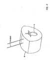
- an access device and/or retractor 101is placed within the percutaneous entry path to provide a space for the insertion of an implant at a later stage of the procedure, as shown in FIGURE 2 . Additionally, the retractor can protect the tissue from damage caused by instruments (e.g., sharp cutting flutes of a cannulated tap).
- the retractor 101in certain examples, is an elongate body having a proximal end 121 and a distal end 111 and having a bore or cannulation 104 extending therebetween. The elongate body has a length such that the proximal end 121 extends out from the skin when the distal end 111 is adjacent the vertebral site.
- the bore 104has an inside diameter that is slightly larger than the width of implants to be delivered therethrough.
- the elongate bodymay include one or more slots 102 or openings to provide an increased amount of access to the vertebral sites.
- the elongate bodyhas a generally "C"-shaped cross section, wherein the opening in the "C" comprises a slot 102 that extends between the proximal 121 and distal 111 ends. Certain such examples also have a shorter slot or opening at the distal end to provide further access to implants at the target site.
- the proximal end 121 of the retractormay be fashioned into a hex-shape (or other suitable shape) to permit instruments, handles, etc. to grasp and firmly hold the retractor.
- the outside surface of the retractormay be threaded or ribbed to prevent the retractor from migrating during the procedure.
- the retractormay be configured to permit other instruments (e.g., a visualization instrument) to be attached thereto.
- the retractoris fabricated from a substantially rigid material such as a metal (e.g., stainless steel or titanium).
- the retractoris made from plastic, which advantageously can electrically insulate body tissue from implants and instruments within the bore of the retractor.
- the retractorcan be made of material (such as plastic or thin metal) which is radiolucent, allowing for fluoroscopic visualization through the retractor.
- the retractoris inserted into the dilated percutaneous access path and advanced through the tissue tunnel until the distal end is adjacent the target site.
- the retractor 101may be advanced over the guidewire 2000 using a cannulated obturator 105 (or cannulated dilator) as schematically illustrated, for example, in FIGURE 2 .
- Additional retractorscan be positioned so as to provide access to additional target sites.
- the openings in adjacent retractorsmay be aligned so as to face each other.
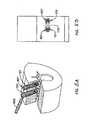
- a cannulated tap 106is a low profile instrument that has an elongate body and an outside surface. The elongate body extends between a proximal end and a distal end. A bore, or cannulation, is formed through the elongate body between the proximal and distal ends. The elongate body has formed thereon a structure 107 configured to form internal threads within the pedicle tunnel, e.g., on the outer surface.
- the cannulated tap 106may be advanced over, e.g., slid over, the guidewire until the distal end is at the vertebral target site.
- FIGURE 2is a cutaway perspective view that schematically illustrates the cannulated tap 106 being advanced over the guidewire 2000 and through the bore 104 in a retractor 101. Thereafter the cannulated tap may be rotated about the guidewire and advanced, turning the cannulated tap into the pedicle tunnel. As the cannulated tap advances the threads are formed in the pedicle tunnel. Tapping creates threads in the pedicle tunnel that will mate with corresponding threads on an implant to be inserted later.
- An implantsuch as, for example, a fastener (e.g., a pedicle screw) can be inserted into and advanced to the target location through the bore in the retractor.
- a fastenersuch as, for example, a cannulated pedicle screw
- a cannulated screwdriver or other instrumentcan be used to move the fastener through the access device to the vertebral site, where it can be attached to the pedicle and vertebral body (e.g., by screwing with the cannulated screwdriver).
- the screwdriver and the guidewirecan be removed, leaving the fastener and retractor in place.
- the fasteneris a screw with an extended breakoff head.
- FIGURES 3A and 3Binclude side views (from two roughly perpendicular directions) schematically showing an embodiment of a screw 801 with an extended breakoff head 821.
- the fastenermay comprise an elongated screw portion 811 extending along a longitudinal axis and having threads configured to mate with the threads formed in the pedicle tunnel by the cannulated tap.
- the screw portion 811may be cannulated to permit passage over a guidewire.
- the screw portion 811 of the fasteneris attached to a breakoff head 821 that comprises a housing 823 and an elongated body 825.
- the housing 823is configured to retain a fixation element 140.
- the housing 823may include a portion that is substantially "U"-shaped in a longitudinal cross-section relative to the longitudinal axis.
- a portion of a fixation element 140e.g., an end of a fixation rod
- the housing 823may be configured with facets 828 (such as a hex shape) that can couple to other tools such as a screw head cutter (described further below).
- the head 821 of the fastener shown in FIGURES 3A and 3Bfurther comprises the breakoff head, which is an elongated body 825 attached to the housing 823 at a neck 826 and extending to a proximal end 829.
- the breakoff head 821has a length between the neck 826 and the proximal end 829 that is sufficient for the proximal end 829 to extend above the skin of the patient when the fastener is secured to the target site.
- a fastenercan be advanced to the target site by manually holding the proximal end and guiding the screw portion through the bore of the retractor and into, e.g., the pedicle tunnel.
- the proximal end of the fastenerremains outside the patient. Accordingly, such a fastener is readily accessible to the physician, unlike certain smaller fasteners that can be difficult to access when placed at the target site at the distal end of the tissue tunnel.
- the length of the breakoff headis sufficient for the proximal end to extend above the retractor so that the proximal end can be coupled to other instruments.
- the breakoff head 821has an outer surface 827 that may be shaped (e.g., with a hex shape) to permit such coupling to instruments such as, e.g., a countertorque handle or removal device.
- the breakoff head 821has a bore or cannulation 802 extending between the neck 826 and the proximal end 829 to permit passage of the fastener 801 over a guidewire.
- the outer surface 827 of the breakoff head 821comprises one or more slots 804 or openings to assist or guide passage of a fixation element (e.g., a fixation rod) to the target site.
- a fixation elemente.g., a fixation rod
- a first slot 804extends the entire length of the outer surface on one side of the breakoff head.
- the breakoff headhas a proximal portion that is substantially "C"-shaped in a transverse cross section relative to the longitudinal axis.
- a second slot 803 on the opposing sidemay extend from the neck part way to the proximal end.
- the first and second slots 803, 804align with the opening defined with the arms of the "U"-shaped housing 823 to permit portions of the fixation element to be positioned within the housing 823.
- the head 821has an elongated body 825 extending along a longitudinal axis and has a distal portion 823 that is substantially "U"-shaped in a longitudinal cross section relative to the longitudinal axis.
- the elongated body 825has a proximal portion that is substantially "C"-shaped in a transverse cross section relative to the longitudinal axis.
- a first slot 804is defined in the substantially “C”-shaped proximal portion and a second slot 803 is defined in the substantially "U"-shaped distal portion, and the first slot is aligned with the second slot.
- the housing 823includes a portion that is substantially "U”-shaped in a longitudinal cross-section relative to the longitudinal axis, and the substantially “U”-shaped distal portion of the elongate body 825 is aligned with the substantially "U''-shaped portion of the housing.
- the fastenermay be fabricated from a substantially rigid material such as a metal (e.g., stainless steel or titanium).
- the breakoff head and the housinggenerally may be integrally machined from the same material.
- the neckis configured so that the breakoff head can be detached from the housing and then removed from the patient.
- the neck 826may comprise a region of material having a reduced cross sectional area compared to other regions of the breakoff head. Accordingly, when a differential torque or shearing force is applied between the housing and the breakoff head, the neck will mechanically fail (e.g., break, snap, or fracture) when the applied torque or shearing force reaches a sufficiently large value (e.g., a yield stress of the material).
- the neck 826comprises one or more grooves 805 cut into the outer surface (and/or an inner surface) of the breakoff head to provide the reduced cross section suitable for the breakoff feature of the neck (see detail B in FIG. 3B ).
- the breakoff featureis achieved by, for example, perforating the neck or by any other suitable mechanism that reduces the yield stress at the neck.
- FIGURE 4is a perspective cutout view that schematically illustrates a stage in the example procedures when two fasteners with extended breakoff heads 821 are positioned over guidewires 2000 within adjacent retractors 101.
- Each fasteneris aligned so that the first slot 804 in the breakoff head 821 aligns with the slot 102 in the "C"-shaped retractor 101.
- the adjacent retractorsare aligned so that the slots are generally aligned with each other.
- the aligned slots in adjacent retractors and breakoff headsdefine guides for opposing ends of a fixation element to be advanced to the target site as further described below.
- the guidewiresare removed from the patient after insertion of the fasteners.
- two separate incisionsare made and two retractors are inserted and a fixation element is inserted through one retractor as discussed above.
- an incisionis made between the two adjacent retractors, along an imaginary line joining the aligned slots of the retractors. The incision extends below the skin and through tissue to the adjacent target vertebral sites. The incision creates a percutaneous path for the insertion of a suitable fixation element.
- the percutaneous pathis a portion of a plane defined between adjacent retractors and may be referred to herein as a tissue plane.
- the fixation elementis advanced through the tissue plane with the aid of a grasping instrument.
- the generally aligned slots in the "C"-shaped retractor and breakoff headdefine a guide for advancing an end of the fastener toward the housing of the fastener at the target site.
- opposing ends of the fixation elementare placed within the guides formed by opposing retractor/breakoff heads, and the fixation element is advanced through the tissue plane to the vertebral site.
- the guidesprovide several benefits. For example, the guides assist in keeping the fixation element in the tissue plane as it is advanced to the target site and facilitate insertion of the ends of the fixation element into the housings of the fasteners.
- FIGURES 5A and 5Binclude a top view ( FIG. 5B ) that schematically illustrates the generally aligned "C"-shaped retractors 101 and breakoff heads 821 and the fixation element 140 (here, a rod) with opposite ends disposed in the guides.
- the fixation elementis placed within a guide, and the fixation element is advanced to the target site, for example, by advancing the fixation element at an angle.
- the ends of the elementare positioned within the housings of the fasteners and then secured, e.g., by cap screws.
- the cap screwis advanced through the bore of the extended breakoff head to reach the housing of the fastener.
- the housinghas an inner surface which is threaded to receive the cap screw.
- the threads in the housingextend into the inner surface of the breakoff head near the neck which beneficially permits the cap screw to engage the threads at a more accessible, proximal position.
- An instrument such as a screwdrivercan be used to tighten the cap screws.
- a countertorque handle 600is attached to the proximal end of the breakoff head 821 (which extends above the proximal end of the retractor) and is used to provide countertorque while the cap screws are being tightened.
- an elongated tube having a notch at a distal end configured to mate with the fixation elementis advanced over the breakoff head so that countertorque can be applied to the fixation element.
- a grasping instrumentis used to apply countertorque to the fixation element. If desired, compression and/or distraction of the vertebrae may be performed prior to the final tightening of the cap screws.
- FIGURE 6is a perspective view that schematically illustrates a stage of the example procedure when the screw head cutter 602 has been attached to the breakoff head disposed in the retractor 101 on the right side of the drawing in preparation for detachment from the housing.
- FIGURE 6also illustrates the retractor 101 on the left side of the drawing in which the breakoff head has been removed.
- FIGURE 7is a perspective view schematically illustrating a stage in an example two-level spinal procedure, for example, a two-level fixation or stabilization procedure.
- the screw head cutter 602is attached to the breakoff head 821 in the rightmost retractor 101 in preparation for detachment and removal from the patient.
- the breakoff headhas been removed from the middle retractor, while the breakoff head 821 is still within the leftmost retractor 101 at this stage.
- the devices and methods presented hereinare suitable for use in one-level as well as two-level or multi-level spinal procedures.
- FIGURES 8-9schematically illustrate an embodiment of a screw head cutter 602 which is generally similar to the screw head cutter illustrated in FIGURES 6-7 .
- the screw head cutter 602is adapted to detach a breakoff head 821 from a housing in a fastener by, for example, exerting a differential torque or shearing force between the breakoff head 821 and the housing 823.
- FIGURE 8is a perspective view and FIGURE 9 is an exploded perspective view.
- the cuttercomprises a first 604 and second 606 handle, an inner sleeve 608, and an outer sleeve 610.
- the first and second handles 604, 606each comprise a central annular portion 612 that can be attached to a proximal end of the inner sleeve and the outer sleeve, respectively.
- the ends of the sleevesmay comprise a hex shaped portion 614 that is configured to mate with hex-shaped facets 616 on an inner surface of the central annular portion 612 of the handles 604, 606 (see FIG. 9 ).
- the inner and outer sleevesare each elongated bodies configured so that the inner sleeve can be disposed within a central cavity in the outer sleeve.
- the inner and outer sleevesmay comprise generally cylindrical tubes with the outer diameter of the inner sleeve being slightly less than the inner diameter of the central cavity in the outer sleeve so that the inner sleeve can slide into the outer sleeve.
- the exploded views in FIGURE 9illustrate a possible method of assembling the screw head cutter.
- the second handle 606is attached to the proximal end of the outer sleeve 610, and the inner sleeve 608 is inserted into the central cavity in the outer sleeve 610.
- the proximal end of the inner sleevehas an enlarged cross section (compared to the elongated tubular portion), which prevents the inner sleeve from sliding through the outer sleeve and which extends above the proximal end of the outer sleeve.
- the first handle 604is then attached to the proximal end of the inner sleeve 608.
- the inner sleevecan rotate within the outer sleeve, hence, forces applied to one or both handles can be used to turn the inner sleeve relative to the outer sleeve.
- the inner sleevecomprises a passageway with a cross-sectional shape that permits the inner sleeve to slide onto the breakoff head, thereby substantially surrounding the breakoff head.
- An inner surface of the passagewaymay be configured with facets (e.g., hex cuts) that mate with corresponding facets (e.g., a hex shape) on the outer surface of the breakoff head.
- the passagewayis disposed substantially centrally within the inner sleeve.
- the cross-sectional shape of the passagewayresembles the cross-sectional shape of the breakoff head.
- the passagewaycan be "C"-shaped to accommodate a "C"-shaped breakoff head.
- the screw head cutteris coupled to a fastener by guiding the cutter onto the breakoff head so that the inner sleeve passes over the breakoff head (as described above).
- the outer sleevemay be slightly longer than the inner sleeve so that a distal end of the outer sleeve engages the housing of the fastener. Accordingly, the inner sleeve engages the breakoff head, and the outer sleeve engages the housing, so that forces applied to the first and second handles tend to cause a relative rotation of the inner and outer sleeves. The relative rotation exerts a shear stress on the breakoff head, which as described above, fails mechanically at the neck, thereby detaching the breakoff head from the housing.
- the second handleis held firmly so as not to rotate the housing (which is coupled to the vertebral site by the screw portion).
- a forceis applied to the first handle to cause the inner sleeve to rotate and snap off the breakoff head.
- One techniquethereby reduces the transfer of shear stresses to the vertebrae during the detachment procedure. After the breakoff head is detached from the housing, the breakoff head is removed from the patient.
Landscapes
- Health & Medical Sciences (AREA)
- Orthopedic Medicine & Surgery (AREA)
- Surgery (AREA)
- Life Sciences & Earth Sciences (AREA)
- Neurology (AREA)
- Molecular Biology (AREA)
- Veterinary Medicine (AREA)
- Medical Informatics (AREA)
- Biomedical Technology (AREA)
- Animal Behavior & Ethology (AREA)
- General Health & Medical Sciences (AREA)
- Public Health (AREA)
- Heart & Thoracic Surgery (AREA)
- Engineering & Computer Science (AREA)
- Nuclear Medicine, Radiotherapy & Molecular Imaging (AREA)
- Pathology (AREA)
- Surgical Instruments (AREA)
- Prostheses (AREA)
- Accommodation For Nursing Or Treatment Tables (AREA)
Description
- This application relates to surgical systems, assemblies and devices that may be used for less invasive and/or minimally invasive surgery, and in particular relates to surgical systems, assemblies and devices that may relate to gaining access to and/or treatment of the spine.
- Spinal surgery presents significant difficulties to the physician attempting to reduce chronic back pain or correct spinal deformities without introducing additional trauma due to the surgical procedure itself. In order to access the vertebrae to perform spinal procedures, the physician is typically required to make large incisions and cut or strip muscle tissue surrounding the spine. In addition, care must be taken not to injure nerve tissue in the area. Consequently, traditional surgical procedures of this type carry high risks of scarring, pain, significant blood loss, and extended recovery times.
- Systems, assemblies, devices, and methods for performing less invasive and/or minimally invasive techniques have been proposed to reduce the trauma of posterior spinal surgery by reducing the size of the incision and the degree of muscle stripping in order to access the vertebrae. A number of different such systems, assemblies, devices, and methods are known, each having certain advantages and disadvantages. Document
WO 2004/041100 A1 discloses a pedicle screw assembly comprising a threaded shaft, a head including a housing and an elongated body connected to the housing, the housing configured to receive a fixation element, the housing attached to the elongated body at a break off section wherein the elongated body is adapted to be removed from the housing at the break off section and the elongated body has a length sufficient such that the elongated body extends above a patient's skin when the screw is secured to the patient's vertebra. However, there is an ongoing need to provide alternative systems, assemblies, devices, and methods for gaining access to and/or treating the spine of a patient. - The invention provides an assembly as claimed in claim 1.
- Preferred embodiments are disclosed in the dependent claims.
- Some example embodiments relate to an access device for providing access to a spinal location within a patient. The access device may include an elongate body having a proximal portion and a distal portion and a length therebetween such that when the distal portion is positioned inside the patient adjacent the spinal location, the proximal portion extends outside the patient. The device may also includes a passage extending through the elongate body between the proximal and distal portions, and one or more channels and/or laterally facing openings and/or cutouts in the distal portion that may be sized and/or configured to permit a fixation element to pass through. In some example embodiments, the distal portion may be expandable from a first non-expanded configuration to a second, expanded configuration.
- Some example embodiment relates to a spinal access assembly including two or more spinal access devices, each access device having an elongate body with a proximal portion and a distal portion and a length therebetween such that when the distal portion is positioned inside a patient adjacent a spinal location, the proximal portion extends outside the patient. The spinal access devices may also have a passage extending through the elongate body between the proximal and distal portions, and one or both of the access devices may include one or more channels and/or laterally facing openings and/or cutouts in the distal portion that may be sized and/or configured to permit a spinal fixation element to pass through. In some example embodiments, the distal portion of one or both of the access devices may be expandable from a first non-expanded configuration to a second, expanded configuration.
- Some example embodiments also relate to a spinal access and treatment assembly that may include two or more spinal access devices, such as any of those discussed above, or hereinafter, and a spinal fixation element, and two or more spinal fasteners configured to affix the spinal fixation element to vertebrae of a patient.
- Additional examples relate to methods for treating the spine of a patient. Some such embodiments may involve the use of two or more access devices, for example, any of those discussed herein. One example method may include inserting a first access device through a first incision in the skin of the patient, the first access device having a first proximal end and a first distal end and a first passage therebetween, wherein a portion of the first distal end has a first opening, and advancing the first access device until the first distal end is adjacent a first spinal location. The method may also include inserting a second access device through a second incision in the skin of the patient, the second access device having a second proximal end and a second distal end and a second passage therebetween, wherein a portion of the second distal end has a second opening, and advancing the second access device until the second distal end is adjacent a second spinal location. A spinal fixation element having a proximal end and a distal end may be inserted through the first passage until the distal end of the fixation element is adjacent the first spinal location. The distal end of the fixation element may be advances through the first opening and through the second opening to the second spinal location, until the proximal end of the fixation element is adjacent the first spinal location and the distal end of the fixation element is adjacent the second spinal location.
- Another example method for treating the spine of a patient may include advancing a first access device into the patient such that a distal end of the first access device is adjacent a first spinal location, wherein a portion of the distal end of the first access device may include a channel and/or cutout and/or laterally facing opening. The method may also include advancing a second access device into the patient such that a distal end of the second access device is adjacent a second spinal location, wherein a portion of the distal end of the second access device may include a channel and/or cutout and/or laterally facing opening. A fixation element having a proximal end and a distal end may be inserted through the first access device until the distal end of the fixation element is adjacent the first spinal location, and the fixation element may be advanced through the a channel and/or cutout and/or laterally facing opening of the first access device and through the channel and/or cutout and/or laterally facing opening in the second access device, until the proximal end of the fixation element is adjacent the first spinal location and the distal end of the fixation element is adjacent the second spinal location.
- A further example method for treating the spine of a patient may include inserting a first retractor through a first incision in the skin of the patient, the first retractor having a first proximal end and a first distal end and a first passage therebetween, wherein a portion of the first distal end may have a first channel and/or cutout and/or laterally facing opening. The method may also includes advancing the first retractor until the first distal end is adjacent a first spinal location, and inserting a second retractor through a second incision in the skin of the patient, the second retractor having a second proximal end and a second distal end and a second passage therebetween, wherein a portion of the second distal end may have a second channel and/or cutout and/or laterally facing opening. The method may also include advancing the second retractor until the second distal end is adjacent a second spinal location, and inserting a fixation rod having a proximal end and a distal end through the first passage and channel and/or cutout and/or laterally facing opening of the first retractor and into the channel and/or cutout and/or laterally facing opening of the second retractor until the distal end of the fixation rod is adjacent the second spinal location and the proximal end of the fixation rod is adjacent the first spinal location.
- The above summary of some embodiments is not intended to describe each disclosed embodiment or every implementation of the present invention. The Figures, and Detailed Description which follow more particularly exemplify these embodiments.
- Further objects, features and advantages of the invention will become apparent from the following detailed description taken in conjunction with the accompanying figures showing illustrative embodiments of the invention, in which:
FIGURES 1-2 schematically illustrate embodiments of apparatuses used in an example spinal procedure for at least partially percutaneously delivering an implant to a vertebral site.FIGURES 3A-3B schematically illustrate an embodiment of a screw with a breakoff head.FIGURES 4-7 schematically illustrate example methods for inserting embodiments of screws with breakoff heads and for removing the breakoff heads from the screws.FIGURES 8-9 schematically illustrate various views of an embodiment of a screw head removal tool that can be used to remove the breakoff heads, for example, from the example screws shown inFIGURES 3A-3B .- Throughout the figures, the same reference numerals and characters, unless otherwise stated, are used to denote like features, elements, components or portions of the illustrated embodiments. Moreover, while the subject matter of this application will now be described in detail with reference to the figures, it is done so in connection with the illustrative embodiments. It is intended that changes and modifications can be made to the described embodiments without departing from the true scope of the subject invention as defined by the appended claims.
- Various embodiments of apparatuses and procedures described herein will be discussed in terms of minimally invasive procedures and apparatuses, e.g., of endoscopic apparatuses and procedures. However, many aspects of the present invention may find use in conventional, open, and mini-open procedures. As used herein, the term "proximal," as is traditional, refers to the end portion of the apparatus that is closest to the operator, while the term "distal" refers to the end portion that is farthest from the operator.
- The systems are described herein in connection with minimally invasive postero-lateral spinal surgery. One such procedure is a two level postero-lateral fixation and fusion of the spine involving the L4, L5, and S1 vertebrae. In the drawings, the vertebrae will generally be denoted by reference letter V. The usefulness of the apparatuses and procedures is neither restricted to the postero-lateral approach nor to the L4, L5, and S1 vertebrae. The apparatuses and procedures may be used in other anatomical approaches and with other vertebra(e) within the cervical, thoracic, and lumbar regions of the spine. The procedures may be directed toward surgery involving one or more vertebral levels. Some embodiments are useful for anterior and/or lateral procedures. Moreover, it is believed that embodiments of the invention are also particularly useful where any body structures must be accessed beneath the skin and muscle tissue of the patient, and/or where it is desirable to provide sufficient space and visibility in order to manipulate surgical instruments and treat the underlying body structures. For example, certain features or instrumentation described herein are particularly useful for minimally invasive procedures, e.g., arthroscopic procedures. As discussed more fully below, one embodiment of an apparatus described herein provides an access device that provides retraction, allows visualization of a spinal location, and provides a passage for surgical instruments. In some embodiments, the access device acts as a retractor. In one embodiment the access device has an expandable distal portion. In other embodiments, the access device is not expandable. In addition to providing greater access to a surgical site than would be provided with device having a constant cross-section, the expandable distal portion prevents or substantially prevents the access device, or instruments extended therethrough to the surgical site, from dislodging or popping out of the operative site.
- Some of the systems disclosed herein can be used to access a surgical location at or near the spine of a patient to enable procedures on the spine. These procedures can be applied to one or more vertebral levels, as discussed herein. Additional procedures and combinations of procedures that may be performed using the systems described herein are discussed below. In various forms, these procedures involve an anterior lumbar interbody fusion, a minimally invasive lumbar interbody fusion, and other procedures particularly enabled by the access devices and systems described herein. These procedures may be performed primarily through retractors or other similar access devices, such as those discussed herein. In some techniques, the procedures may be at least partially performed percutaneously, e.g., over a guidewire or other structure that has a smaller profile than the access devices describe herein. By performing at least a portion of the procedures percutaneously, the amount of time that a retractor or similar access device is deployed or expanded may be reduced. Also, percutaneous techniques described herein increase the ability of the surgeon to quickly and easily deliver place markers, fasteners, and other implants to target sites, to prepare target sites, and to complete procedures. Percutaneous techniques enable the performance of a substantial portion of a spinal procedure with little or no visualization of the location where the procedure is performed.
- Accordingly, it is desirable to provide systems and devices for percutaneous and partially percutaneous access that reduce tissue trauma, require less surgical time, and reduce the need for fluoroscopy and image-guided assistance. In some embodiments, the systems and devices permit posterolateral fixation and/or fusion procedures to be performed at least partially percutaneously.
- In one example, the system includes an access device that provides an internal passage for surgical instruments to be inserted through the skin and muscle tissue of the patient to the surgical site. The term "access device" is used in its ordinary sense to mean a device that can provide access and is a broad term and it includes structures having an elongated dimension and defining a passage, e.g., a cannula or a conduit. The access device is configured to be inserted through the skin of the patient to provide access during a surgical procedure to a surgical location within a patient, e.g., a spinal location. The access device may provide distraction with or without having an expandable component. The term "surgical location" is used in its ordinary sense (i.e. a location where a surgical procedure is performed) and is a broad term and it includes locations subject to or affected by a surgery. The term "spinal location" is used in its ordinary sense (i.e. a location at or near a spine) and is a broad term and it includes locations adjacent to or associated with a spine that may be sites for surgical spinal procedures.
- One example of the access device includes a wall portion defining a reduced profile configuration for initial percutaneous insertion into the patient. This wall portion may have any suitable arrangement. In one example the wall portion has a generally tubular configuration that may be passed over a dilator that has been inserted into the patient to atraumatically enlarge an opening sufficiently large to receive the access device therein.
- The wall portion of the access device can be subsequently expanded to an enlarged configuration, by moving against the surrounding muscle tissue to at least partially define an enlarged surgical space in which the surgical procedures will be performed. Accordingly, the expanded wall portion may act similarly to a dilator. Both the distal and proximal portion may be expanded. However, the distal portion may expand to a greater extent than the proximal portion, because the surgical procedures are to be performed at the surgical site, which is adjacent the distal portion when the access device is inserted into the patient.
- While in the reduced profile configuration, the access device defines a first unexpanded configuration. Thereafter, the access device can enlarge the surgical space defined thereby by engaging the tissue surrounding the access device and displacing the tissue outwardly as the access device expands. In some embodiments, the access device is sufficiently rigid to displace such tissue during the expansion thereof. The access device may be resiliently biased to expand from the reduced profile configuration to the enlarged configuration. In addition, the access device may also be manually expanded by an expander device with or without one or more surgical instruments inserted therein. The surgical site is at least partially defined by the expanded access device itself. During use, the access device can move from a first unexpanded configuration to a second expanded configuration.
- In some examples, the proximal and distal portions are separate components that may be coupled together in a suitable fashion. For example, the distal end portion of the access device may be configured for relative movement with respect to the proximal end portion in order to allow the physician to position the distal end portion at a desired location. This relative movement also provides the advantage that the proximal portion of the access device nearest the physician may remain substantially stable during such distal movement. In one example, the distal portion is a separate component that is pivotally or movably coupled with the proximal portion. In another example, the distal portion is flexible or resilient in order to permit such relative movement. The access device is configured such that the proximal portion can pivot in at least one direction with respect to the distal portion.
- As discussed above, the systems disclosed herein can be used to access a surgical location at or near the spine of a patient to enable procedures on the spine. These procedures can be applied to one or more vertebral levels, as discussed herein. Additional procedures and combinations of procedures that may be performed using the systems described herein are discussed below. In various forms, these procedures involve an anterior lumbar interbody fusion, a minimally invasive lumbar interbody fusion, and other procedures particularly enabled by the access devices and systems described herein. The procedures may be partially or completely performed percutaneously, e.g., over a guidewire or other structure that has a smaller profile than the access devices describe herein.
- Certain of the procedures described herein can be performed in part percutaneously and in part minimally invasively, e.g., through an access device. In some methods, a device that includes a hollow structure is used to form a percutaneous entry or path between the skin and a vertebral surface or a vertebral target site. In other procedures, the percutaneous entry or path may be formed between the skin of the patient and a suitable target site on or near the spine of the patient. A vertebral target site is any site on a vertebra at which a procedure or a portion of a procedure is to be performed. For example, as discussed below, some procedures may advantageously be performed at a pedicle of a vertebra or at a region between a facet joint and a transverse process of a vertebra. In one technique the hollow structure of the percutaneous entry forming device is configured to receive a sharp implement, which is configured to cut and separate tissue. As tissue is cut and separated, the percutaneous access path can be formed between the skin and the vertebral surface.
- In some percutaneous methods, cannulated fasteners (e.g., pedicle screws) are implanted through tissue over a guidewire to a vertebral target site, for example, the lumbar region of the spine. In some examples, after the fasteners are attached to the target site, a fixation member (e.g., a rod or a plate) is implanted as part of a fusion or fixation procedure. However, certain fixation member implantation methods require an additional incision and muscle dissection for placement of the fixation member and/or require cutting or splitting the tissue between the fasteners from the skin distally to place and secure the fixation member. Also, some methods employ but may not require fluoroscopic or image-guided assistance to place the fasteners at the target site.
- Accordingly, it is desirable to provide systems and devices for percutaneous access that reduce tissue trauma, require less surgical time, reduce the need for fluoroscopy and image-guided assistance. In some embodiments, the systems and devices permit posterolateral fixation and/or fusion procedures to be performed at least partially percutaneously.
- In certain examples, the methods involve creating a pedicle tunnel "percutaneously" using, for example, guidewires and implants and instruments that can be delivered thereover. Additionally, one or more such methods can be at least partially performed through one or more small tubular retractors. In certain examples, the retractors comprise an expandable portion as described herein. After the implants are in place in each retractor, the distal portions of the retractors can be adjusted to form a tunnel to permit a fixation member to be inserted proximally through one of the retractors and then positioned onto a fastener distally. In some examples, the tunnel is formed by expanding the distal portions of one or more retractors. The fixation member (e.g., a rod or a plate) can be positioned onto the fastener without the need for an additional incision or muscle splitting. A benefit of some examples of this method is that, where fixation assemblies are to be deployed on both sides of the spinous process, only two small incisions per side of the spinous process are made for a single-level procedure.
- Some examples of the procedures disclosed herein reduce tissue trauma, because less cutting and splitting of the muscles, fat, and fascia is required. In some procedures, an endoscope and/or lighting devices for visualizing the anatomy can be positioned within one or more of the tubular retractors. Additionally, manipulation of the fasteners (e.g., screw heads) for compression or distraction of the joint space between the fasteners can also be performed with these methods. Examples of the methods disclosed herein are suitable for fixation or fusion procedures and may be used with any suitable spinal approach such as, for example, a posterolateral approach.
- The following is a non-limiting and nonexclusive list that comprises actions that may be performed in one example of a spinal surgical technique (e.g., a one-level spinal fixation procedure). Additional and/or different actions can be performed in other spinal procedures according to other techniques. Further, the actions may be performed in a different order than shown, and some of the enumerated actions may be eliminated in other techniques.
- One example involves a method for an at least partially percutaneous spinal procedure. The procedure may include, for example, a fixation, a fusion, and/or other suitable stabilization procedure. In this example procedure, a trocar and needle (such as a Jamshidi needle or bone biopsy needle) are percutaneously passed through the skin and into the targeted pedicle and into the vertebral body. The trocar and needle form a percutaneous access path that is sometimes referred to herein as a tissue tunnel. In one technique, the trocar is inserted into the needle and the trocar and needle are advanced together through the skin at a skin puncture location and through subcutaneous tissue (e.g., through fat, muscle, and fascia) until a distal end of the trocar and needle are at the vertebral target site. The needle and trocar thus create a tissue tunnel through subcutaneous tissue. In one exemplary method, a generally posterolateral approach is employed and the initial advancement of the needle and trocar positions the needle and trocar at the pedicle of the target vertebra. Advancement of the needle and trocar may be aided by fluoroscopy, e.g., using a C-arm or other similar technique.
- After a percutaneous entry, or percutaneous entry path, has been created through the skin and subcutaneous tissue, the vertebral target site may be prepared, if desired. In one method, the needle and trocar are advanced further into the target vertebra at the vertebral target site to form a tunnel in the target vertebra. The tunnel may be formed in the pedicle and is sometimes referred to as a pedicle tunnel. A proximal end of the trocar remains outside the patient, above the skin puncture location throughout the target site preparation. Preparation of the vertebral target site may include further procedures, such as tapping of the pedicle tunnel.
- In one example, the trocar is removed, leaving the needle in the pedicle. A guidewire, or other elongate body, is inserted into the proximal end of the needle. The guidewire may be advanced through the tissue tunnel and through the pedicle tunnel within the needle. In one application, the guidewire is advanced until a distal end of the guidewire is located in the vertebral body of the target vertebra. The guidewire extends proximally from of the skin and of the proximal end of the needle. The needle is removed leaving the guidewire in place, extending distally into the pedicle tunnel and proximally out of the skin.
- Optionally, it may be advantageous to prepare the pedicle tunnel by forming threads within the tunnel. One method of forming threads in the pedicle tunnel involves tapping the pedicle tunnel with a cannulated tap. A cannulated tap is a low profile instrument that has an elongate body and an outside surface. The elongate body extends between a proximal end and a distal end. A bore, or cannulation, is formed through the elongate body between the proximal and distal ends. The elongate body has formed thereon a structure configured to form internal threads within the pedicle tunnel, e.g., on the outer surface. The cannulated tap may be advanced over, e.g., slid over, the guidewire until the distal end is at the vertebral target site. Thereafter the cannulated tap may be rotated about the guidewire and advanced, turning the cannulated tap into the pedicle tunnel. As the cannulated tap advances the threads are formed in the pedicle tunnel. Tapping creates threads in the pedicle tunnel that will mate with corresponding threads on an implant to be inserted later.
- In some applications, further dilation of the percutaneous access path or entry facilitates insertion of an implant. In one technique, a small incision is created at the skin puncture location. In one technique, an incision is created that is about 5-15 mm long. In some variations, an incision that is less than 5 mm can be created. The incision also can extend a distance into the tissue beneath the skin. The incision facilitates the insertion of one or more dilators (or obturators) over the wire to increase the size of the percutaneous access path or entry. The dilator may be advanced at least a substantial portion of the distance from the skin puncture location to the surface of the vertebra to reduce the resistance of the tissue beneath the skin to the insertion of an implant. The dilators are removed prior to insertion of an implant in one technique. The dilators/obturators may be inserted at the access site to create a tunnel through the tissue to the pedicle.
- Although significant advantages are realized by preparing the vertebral target site prior to insertion of an access device, blood and other body fluids and tissues can hide or obscure the location of the prepared site. After the percutaneous access path or entry has been created, a marker may be delivered over the guidewire to the vertebral target site. Placing a marker within the pedicle tunnel aids the surgeon in finding the pedicle tunnel later in the procedure. Further details of a marker suitable for use with methods discussed herein is disclosed in
U.S. Patent Application No. 11/184,568, filed July 19, 2005 US-A-2006 030 850 . - In one method, an access device is inserted into the patient to enclose one or more of the adjacent pedicles in a working space so that a minimally invasive portion of a procedure may be performed. In particular, an incision may be created by connecting, by extending, or by connecting and extending the incisions made for the guidewires. After the incision is made, the tissue may be dilated, and an access device or a retractor may be inserted over the dilator (or obturator). In some embodiments, the access device comprises an expandable distal portion that may be expanded so that the distal portion extends over one or more of adjacent pedicles (and any previously inserted markers). Two tubular retractors may be inserted at two adjacent vertebral sites. In some techniques, after the access device is inserted over the dilator or obturator (or a series of these), the dilator(s) or obturator(s) are removed, leaving the guidewire in place within the access device.
- In one technique, a fastener such as, for example, a cannulated pedicle screw, is inserted over a proximal end of the guidewire. A cannulated screwdriver device can be used to move the fastener through the access device to the vertebral site, where it can be attached to the pedicle and vertebral body (e.g., by screwing with the cannulated screwdriver). In one method, after insertion and attachment of the fastener, the screwdriver and the guidewire can be removed, leaving the fastener and access device in place.
- In some methods, after a first fastener is attached to a first vertebral site (and the guidewire removed), the above techniques are repeated so that a second fastener is attached to a second vertebral site and so on. However, in other methods, a trocar, needle, and guidewire are installed at each of the vertebral sites (e.g., at each pedicle), and then the subsequent acts of expanding the surgical site with a dilator/obturator, inserting the access device, and securing a fastener to the vertebral body (e.g., at a pedicle) are performed.
- Each access device is oriented properly and expanded distally to allow mating openings of the distal portion to align and create a short tunnel for passing a rod or other fixation element between access devices. The screw heads are oriented and aligned with the tunnel to receive the rod. The rod is then placed proximally though one of the access devices and is targeted and positioned to the tunnel opening by a variety of means (e.g., rod holder, slide-like guide, suture thread, wire or cable, etc.). The rod is manipulated (by pushing or pulling or a combination of these) through the tunnel from one access device to the next (and successive retractors if more than 1-level) until the rod is positioned and seated in all screw heads in preparation for placement of a securing means (e.g., cap screw). The rod is secured to each screw head using fixating and delivery instrument means through each access device. Instruments such as countertorque drivers, torque limiting instruments and compressor/distractor instruments may be utilized as desired by the surgeon. Bone graft may be placed through the tubes and around the screws and connecting member as desired.
- It is appreciated that many variations of this method are possible and that the actions described herein can be performed in many ways and in many orders so as to enable access to the vertebral sites. For example, a one-level procedure may involve delivering two fasteners (e.g., pedicle screws) to two adjacent vertebral sites (e.g., L4 and L5) using two access devices.
- In certain examples, the access device provides an internal passage for surgical instruments to be inserted through the skin and muscle tissue of the patient to the surgical site. The access device has a wall portion defining a reduced profile, or low-profile, configuration for initial percutaneous insertion into the patient. This wall portion may have any suitable arrangement. In one example, the wall portion has a generally tubular configuration that may be passed over a dilator that has been inserted into the patient to atraumatically enlarge an opening sufficiently large to receive the access device therein. In some examples, the distal portion of the access device is expanded prior to insertion of a fastener into the access device, while in other methods the distal portion is expanded at a later stage of the procedure.
- In some examples, the proximal and distal portions of the access device are separate components that may be coupled together in a suitable fashion. For example, the distal end portion of the access device may be configured for relative movement with respect to the proximal end portion in order to allow the physician to position the distal end portion at a desired location. This relative movement also provides the advantage that the proximal portion of the access device nearest the physician may remain substantially stable during such distal movement. In one embodiment, the distal portion is a separate component that is pivotally or movably coupled to the proximal portion. In another example, the distal portion is flexible or resilient in order to permit such relative movement.
FIGURES 1-6 schematically illustrate an example spinal procedure for at least partially percutaneously delivering a fixation element 140 (e.g. a fixation rod) to a target site adjacent the vertebrae of a patient. The procedure may include, for example, a fixation, a fusion, and/or other suitable stabilization procedure, and the procedure can be a one-level or multi-level procedure. The target site may be any suitable site on the vertebra of the patient including, for example, a pedicle, a spinous or transverse process, a facet joint, or a combination of such sites. Although a generally posterior approach is illustrated inFIGURES 1-6 (e.g., a postero-lateral approach), in other procedures other spinal approaches may be used such as, for example, anterior, lateral, or retroperitoneal.FIGURE 1 is a perspective view that schematically illustrates a stage in the procedure when twoguidewires 2000 have been delivered to suitable target sites. For example, a trocar and needle (such as a Jamshidi needle or bone biopsy needle) are percutaneously passed through the skin S and into the targeted pedicle and into the vertebral body V. The trocar and needle form a percutaneous access path that is sometimes referred to herein as a tissue tunnel. In one technique, the trocar is inserted into the needle and the trocar and needle are advanced together through the skin at a skin puncture location and through subcutaneous tissue (e.g., through fat, muscle, and fascia) until a distal end of the trocar and needle are at the vertebral target site. The needle and trocar thus create a tissue tunnel through subcutaneous tissue. In one exemplary method, a generally posterolateral approach is employed and the initial advancement of the needle and trocar positions the needle and trocar at the pedicle of the target vertebra. Advancement of the needle and trocar may be aided by fluoroscopy, e.g., using a C-arm or other similar technique.- After a percutaneous entry, or percutaneous entry path, has been created through the skin and subcutaneous tissue, the vertebral target site may be prepared, if desired. In one exemplary method, the needle and trocar are advanced further into the target vertebra at the vertebral target site to form a tunnel in the target vertebra. The tunnel may be formed in the pedicle and is sometimes referred to as a pedicle tunnel. A proximal end of the trocar may remain outside the patient, above the skin puncture location throughout the target site preparation. Preparation of the vertebral target site may include further procedures, such as tapping of the pedicle tunnel.
- In one example, the trocar is removed, leaving the needle in the pedicle. A
guidewire 2000, or other elongate body, is inserted into the proximal end of the needle. The guidewire may be advanced through the tissue tunnel and through the pedicle tunnel within the needle. In one application, the guidewire is advanced until a distal end of the guidewire is located in the vertebral body of the target vertebra. The guidewire extends proximally from the skin and the proximal end of the needle at the stage of the procedure illustrated inFIGURE 1 . In some techniques, the guidewire has an outer diameter of about 1.5 mm. The needle is removed leaving the guidewire in place, extending distally into the pedicle tunnel and proximally out of the skin. In similar manner, additional guidewires can be delivered to other target vertebral sites (e.g.,FIG. 1 schematically illustrates two guidewires). - In some applications, further dilation of the percutaneous access path or entry facilitates insertion of an access device and/or
retractor 101. In certain techniques, a small incision is created at the skin puncture location, which in one technique is about 5-15 mm long. In some variations, an incision that is less than 5 mm can be created. The incision also can extend a distance into the tissue beneath the skin. The incision facilitates the insertion of one or more dilators (or obturators) over the guidewire to increase the size of the percutaneous access path or entry. In some techniques, a cannulated dilator with an outer diameter of about 5 mm is used. The dilator may be advanced at least a substantial portion of the distance from the skin puncture location to the surface of the vertebra to reduce the resistance of the tissue beneath the skin to the insertion of an implant. The dilators are removed prior to insertion of a retractor in one technique. - In certain techniques, an access device and/or
retractor 101 is placed within the percutaneous entry path to provide a space for the insertion of an implant at a later stage of the procedure, as shown inFIGURE 2 . Additionally, the retractor can protect the tissue from damage caused by instruments (e.g., sharp cutting flutes of a cannulated tap). Theretractor 101, in certain examples, is an elongate body having aproximal end 121 and adistal end 111 and having a bore orcannulation 104 extending therebetween. The elongate body has a length such that theproximal end 121 extends out from the skin when thedistal end 111 is adjacent the vertebral site. Thebore 104 has an inside diameter that is slightly larger than the width of implants to be delivered therethrough. In some examples, the elongate body may include one ormore slots 102 or openings to provide an increased amount of access to the vertebral sites. For example, in some examples the elongate body has a generally "C"-shaped cross section, wherein the opening in the "C" comprises aslot 102 that extends between the proximal 121 and distal 111 ends. Certain such examples also have a shorter slot or opening at the distal end to provide further access to implants at the target site. Theproximal end 121 of the retractor may be fashioned into a hex-shape (or other suitable shape) to permit instruments, handles, etc. to grasp and firmly hold the retractor. The outside surface of the retractor may be threaded or ribbed to prevent the retractor from migrating during the procedure. The retractor may be configured to permit other instruments (e.g., a visualization instrument) to be attached thereto. The retractor is fabricated from a substantially rigid material such as a metal (e.g., stainless steel or titanium). In one example, the retractor is made from plastic, which advantageously can electrically insulate body tissue from implants and instruments within the bore of the retractor. The retractor can be made of material (such as plastic or thin metal) which is radiolucent, allowing for fluoroscopic visualization through the retractor. - In some techniques, the retractor is inserted into the dilated percutaneous access path and advanced through the tissue tunnel until the distal end is adjacent the target site. The
retractor 101 may be advanced over theguidewire 2000 using a cannulated obturator 105 (or cannulated dilator) as schematically illustrated, for example, inFIGURE 2 . Additional retractors can be positioned so as to provide access to additional target sites. In techniques using "C"-shaped retractors, the openings in adjacent retractors may be aligned so as to face each other. - Optionally, it may be advantageous to prepare the pedicle tunnel by forming threads within the tunnel. One exemplary method of forming threads in the pedicle tunnel involves tapping the pedicle tunnel with a cannulated
tap 106. A cannulatedtap 106 is a low profile instrument that has an elongate body and an outside surface. The elongate body extends between a proximal end and a distal end. A bore, or cannulation, is formed through the elongate body between the proximal and distal ends. The elongate body has formed thereon astructure 107 configured to form internal threads within the pedicle tunnel, e.g., on the outer surface. The cannulatedtap 106 may be advanced over, e.g., slid over, the guidewire until the distal end is at the vertebral target site.FIGURE 2 is a cutaway perspective view that schematically illustrates the cannulatedtap 106 being advanced over theguidewire 2000 and through thebore 104 in aretractor 101. Thereafter the cannulated tap may be rotated about the guidewire and advanced, turning the cannulated tap into the pedicle tunnel. As the cannulated tap advances the threads are formed in the pedicle tunnel. Tapping creates threads in the pedicle tunnel that will mate with corresponding threads on an implant to be inserted later. - An implant such as, for example, a fastener (e.g., a pedicle screw) can be inserted into and advanced to the target location through the bore in the retractor. In one technique, a fastener such as, for example, a cannulated pedicle screw, is inserted over a proximal end of the guidewire. In some procedures, a cannulated screwdriver or other instrument can be used to move the fastener through the access device to the vertebral site, where it can be attached to the pedicle and vertebral body (e.g., by screwing with the cannulated screwdriver). In one exemplary method, after insertion and attachment of the fastener, the screwdriver and the guidewire can be removed, leaving the fastener and retractor in place.
- In certain techniques, the fastener is a screw with an extended breakoff head.
FIGURES 3A and 3B include side views (from two roughly perpendicular directions) schematically showing an embodiment of ascrew 801 with anextended breakoff head 821. For example, the fastener may comprise anelongated screw portion 811 extending along a longitudinal axis and having threads configured to mate with the threads formed in the pedicle tunnel by the cannulated tap. Thescrew portion 811 may be cannulated to permit passage over a guidewire. Thescrew portion 811 of the fastener is attached to abreakoff head 821 that comprises ahousing 823 and anelongated body 825. Thehousing 823 is configured to retain afixation element 140. For example, thehousing 823 may include a portion that is substantially "U"-shaped in a longitudinal cross-section relative to the longitudinal axis. A portion of a fixation element 140 (e.g., an end of a fixation rod) may be placed within thehousing 823 and secured by, for example, a cap screw 900 as further described herein. Thehousing 823 may be configured with facets 828 (such as a hex shape) that can couple to other tools such as a screw head cutter (described further below). - The
head 821 of the fastener shown inFIGURES 3A and 3B further comprises the breakoff head, which is anelongated body 825 attached to thehousing 823 at aneck 826 and extending to aproximal end 829. Thebreakoff head 821 has a length between theneck 826 and theproximal end 829 that is sufficient for theproximal end 829 to extend above the skin of the patient when the fastener is secured to the target site. Advantageously, such a fastener can be advanced to the target site by manually holding the proximal end and guiding the screw portion through the bore of the retractor and into, e.g., the pedicle tunnel. Because of the length of the breakoff head, the proximal end of the fastener remains outside the patient. Accordingly, such a fastener is readily accessible to the physician, unlike certain smaller fasteners that can be difficult to access when placed at the target site at the distal end of the tissue tunnel. In one embodiment, the length of the breakoff head is sufficient for the proximal end to extend above the retractor so that the proximal end can be coupled to other instruments. - The
breakoff head 821 has anouter surface 827 that may be shaped (e.g., with a hex shape) to permit such coupling to instruments such as, e.g., a countertorque handle or removal device. Thebreakoff head 821 has a bore orcannulation 802 extending between theneck 826 and theproximal end 829 to permit passage of thefastener 801 over a guidewire. In one embodiment, theouter surface 827 of thebreakoff head 821 comprises one ormore slots 804 or openings to assist or guide passage of a fixation element (e.g., a fixation rod) to the target site. In the embodiment shown inFIGURES 3A and 3B , afirst slot 804 extends the entire length of the outer surface on one side of the breakoff head. Thus, the breakoff head has a proximal portion that is substantially "C"-shaped in a transverse cross section relative to the longitudinal axis. Asecond slot 803 on the opposing side may extend from the neck part way to the proximal end. The first andsecond slots housing 823 to permit portions of the fixation element to be positioned within thehousing 823. - In some embodiments, the
head 821 has anelongated body 825 extending along a longitudinal axis and has adistal portion 823 that is substantially "U"-shaped in a longitudinal cross section relative to the longitudinal axis. Theelongated body 825 has a proximal portion that is substantially "C"-shaped in a transverse cross section relative to the longitudinal axis. Afirst slot 804 is defined in the substantially "C"-shaped proximal portion and asecond slot 803 is defined in the substantially "U"-shaped distal portion, and the first slot is aligned with the second slot. Thehousing 823 includes a portion that is substantially "U"-shaped in a longitudinal cross-section relative to the longitudinal axis, and the substantially "U"-shaped distal portion of theelongate body 825 is aligned with the substantially "U''-shaped portion of the housing. - The fastener may be fabricated from a substantially rigid material such as a metal (e.g., stainless steel or titanium). The breakoff head and the housing generally may be integrally machined from the same material. In some embodiments, the neck is configured so that the breakoff head can be detached from the housing and then removed from the patient. For example, the
neck 826 may comprise a region of material having a reduced cross sectional area compared to other regions of the breakoff head. Accordingly, when a differential torque or shearing force is applied between the housing and the breakoff head, the neck will mechanically fail (e.g., break, snap, or fracture) when the applied torque or shearing force reaches a sufficiently large value (e.g., a yield stress of the material). In some embodiments, theneck 826 comprises one ormore grooves 805 cut into the outer surface (and/or an inner surface) of the breakoff head to provide the reduced cross section suitable for the breakoff feature of the neck (see detail B inFIG. 3B ). However, in other embodiments, the breakoff feature is achieved by, for example, perforating the neck or by any other suitable mechanism that reduces the yield stress at the neck. FIGURE 4 is a perspective cutout view that schematically illustrates a stage in the example procedures when two fasteners with extended breakoff heads 821 are positioned overguidewires 2000 withinadjacent retractors 101. Each fastener is aligned so that thefirst slot 804 in thebreakoff head 821 aligns with theslot 102 in the "C"-shapedretractor 101. Additionally, the adjacent retractors are aligned so that the slots are generally aligned with each other. Accordingly, the aligned slots in adjacent retractors and breakoff heads define guides for opposing ends of a fixation element to be advanced to the target site as further described below. In some techniques, the guidewires are removed from the patient after insertion of the fasteners.- In some examples, two separate incisions are made and two retractors are inserted and a fixation element is inserted through one retractor as discussed above. In another embodiment, an incision is made between the two adjacent retractors, along an imaginary line joining the aligned slots of the retractors. The incision extends below the skin and through tissue to the adjacent target vertebral sites. The incision creates a percutaneous path for the insertion of a suitable fixation element. The percutaneous path is a portion of a plane defined between adjacent retractors and may be referred to herein as a tissue plane.
- In some techniques, the fixation element is advanced through the tissue plane with the aid of a grasping instrument. As described above with reference to
FIGURE 4 , the generally aligned slots in the "C"-shaped retractor and breakoff head define a guide for advancing an end of the fastener toward the housing of the fastener at the target site. In one technique, opposing ends of the fixation element are placed within the guides formed by opposing retractor/breakoff heads, and the fixation element is advanced through the tissue plane to the vertebral site. The guides provide several benefits. For example, the guides assist in keeping the fixation element in the tissue plane as it is advanced to the target site and facilitate insertion of the ends of the fixation element into the housings of the fasteners. Also, the use of guides makes it easier to advance the fixation element through the tissue plane, since the portions of the fixation element disposed in the guides do not experience resistance from the tissue.FIGURES 5A and 5B include a top view (FIG. 5B ) that schematically illustrates the generally aligned "C"-shapedretractors 101 and breakoff heads 821 and the fixation element 140 (here, a rod) with opposite ends disposed in the guides. - However, in other techniques, only one end of the fixation element is placed within a guide, and the fixation element is advanced to the target site, for example, by advancing the fixation element at an angle. When the fixation element has reached the target sites, the ends of the element are positioned within the housings of the fasteners and then secured, e.g., by cap screws. In some techniques, the cap screw is advanced through the bore of the extended breakoff head to reach the housing of the fastener. The housing has an inner surface which is threaded to receive the cap screw. In one embodiment, the threads in the housing extend into the inner surface of the breakoff head near the neck which beneficially permits the cap screw to engage the threads at a more accessible, proximal position.
- An instrument such as a screwdriver can be used to tighten the cap screws. As schematically illustrated in
FIGURE 5A , in some techniques, acountertorque handle 600 is attached to the proximal end of the breakoff head 821 (which extends above the proximal end of the retractor) and is used to provide countertorque while the cap screws are being tightened. In other techniques, an elongated tube having a notch at a distal end configured to mate with the fixation element is advanced over the breakoff head so that countertorque can be applied to the fixation element. In some techniques, a grasping instrument is used to apply countertorque to the fixation element. If desired, compression and/or distraction of the vertebrae may be performed prior to the final tightening of the cap screws. - After the fixation element has been secured, the breakoff heads of the fasteners are detached from the housing and removed from the patient. In some techniques a screw head cutter and/or
removal tool 602 is attached to the breakoff head, and a differential torque or shearing force is applied so as to shear (or snap or otherwise break) the breakoff head from the housing.FIGURE 6 is a perspective view that schematically illustrates a stage of the example procedure when thescrew head cutter 602 has been attached to the breakoff head disposed in theretractor 101 on the right side of the drawing in preparation for detachment from the housing.FIGURE 6 also illustrates theretractor 101 on the left side of the drawing in which the breakoff head has been removed. FIGURE 7 is a perspective view schematically illustrating a stage in an example two-level spinal procedure, for example, a two-level fixation or stabilization procedure. At the stage shown, thescrew head cutter 602 is attached to thebreakoff head 821 in therightmost retractor 101 in preparation for detachment and removal from the patient. The breakoff head has been removed from the middle retractor, while thebreakoff head 821 is still within theleftmost retractor 101 at this stage. Thus it is recognized that the devices and methods presented herein are suitable for use in one-level as well as two-level or multi-level spinal procedures.FIGURES 8-9 schematically illustrate an embodiment of ascrew head cutter 602 which is generally similar to the screw head cutter illustrated inFIGURES 6-7 . Thescrew head cutter 602 is adapted to detach abreakoff head 821 from a housing in a fastener by, for example, exerting a differential torque or shearing force between thebreakoff head 821 and thehousing 823.FIGURE 8 is a perspective view andFIGURE 9 is an exploded perspective view.- In the embodiment shown in
FIGURES 8-9 , the cutter comprises a first 604 and second 606 handle, aninner sleeve 608, and anouter sleeve 610. The first andsecond handles annular portion 612 that can be attached to a proximal end of the inner sleeve and the outer sleeve, respectively. For example, the ends of the sleeves may comprise a hex shapedportion 614 that is configured to mate with hex-shapedfacets 616 on an inner surface of the centralannular portion 612 of thehandles 604, 606 (seeFIG. 9 ). The inner and outer sleeves are each elongated bodies configured so that the inner sleeve can be disposed within a central cavity in the outer sleeve. For example, the inner and outer sleeves may comprise generally cylindrical tubes with the outer diameter of the inner sleeve being slightly less than the inner diameter of the central cavity in the outer sleeve so that the inner sleeve can slide into the outer sleeve. The exploded views inFIGURE 9 illustrate a possible method of assembling the screw head cutter. Thesecond handle 606 is attached to the proximal end of theouter sleeve 610, and theinner sleeve 608 is inserted into the central cavity in theouter sleeve 610. The proximal end of the inner sleeve has an enlarged cross section (compared to the elongated tubular portion), which prevents the inner sleeve from sliding through the outer sleeve and which extends above the proximal end of the outer sleeve. Thefirst handle 604 is then attached to the proximal end of theinner sleeve 608. The inner sleeve can rotate within the outer sleeve, hence, forces applied to one or both handles can be used to turn the inner sleeve relative to the outer sleeve. - The inner sleeve comprises a passageway with a cross-sectional shape that permits the inner sleeve to slide onto the breakoff head, thereby substantially surrounding the breakoff head. An inner surface of the passageway may be configured with facets (e.g., hex cuts) that mate with corresponding facets (e.g., a hex shape) on the outer surface of the breakoff head. In some embodiments, the passageway is disposed substantially centrally within the inner sleeve. However, in other embodiments the cross-sectional shape of the passageway resembles the cross-sectional shape of the breakoff head. For example, the passageway can be "C"-shaped to accommodate a "C"-shaped breakoff head. When the inner sleeve is slid onto the breakoff head, a portion of the inner sleeve is disposed within the central bore of the breakoff head, which beneficially can support and stabilize the breakoff head during the detachment procedure.
- The screw head cutter is coupled to a fastener by guiding the cutter onto the breakoff head so that the inner sleeve passes over the breakoff head (as described above). The outer sleeve may be slightly longer than the inner sleeve so that a distal end of the outer sleeve engages the housing of the fastener. Accordingly, the inner sleeve engages the breakoff head, and the outer sleeve engages the housing, so that forces applied to the first and second handles tend to cause a relative rotation of the inner and outer sleeves. The relative rotation exerts a shear stress on the breakoff head, which as described above, fails mechanically at the neck, thereby detaching the breakoff head from the housing. In one technique, the second handle is held firmly so as not to rotate the housing (which is coupled to the vertebral site by the screw portion). A force is applied to the first handle to cause the inner sleeve to rotate and snap off the breakoff head. One technique thereby reduces the transfer of shear stresses to the vertebrae during the detachment procedure. After the breakoff head is detached from the housing, the breakoff head is removed from the patient.
Claims (11)
- A pedicle screw assembly comprising:a threaded shaft (811);a head (821) including a housing (823) and an elongated body (825) integrally formed with the housing, the housing configured to receive a fixation element (140), the housing attached to the elongated body at a frangible neck (826), wherein the elongated body is adapted to be removed from the housing at the frangible neck and the elongated body has a length sufficient such that the elongated body extends above a patient's skin when the screw is secured to the patient's vertebra (V); and
a removal device (602), the removal device including a first handle (604) connected to an inner sleeve (608) and a second handle (606) connected to an outer sleeve (610), the inner sleeve configured to engage the elongated body (825), the outer sleeve configured to engage the housing (823), wherein the inner sleeve is configured to rotate within the outer sleeve such that forces applied to the first and second handles exert a shear stress on the neck (826), breaking the neck and allowing the elongate body to be removed. - The pedicle screw assembly of claim 1, wherein the shaft (811) and head (821) are cannulated.
- The pedicle screw assembly of claim 1 or 2, wherein the housing (823) has one or more facets (828) configured to couple with a removal device (602) and/or wherein the elongated body (825) has an outer surface configured to couple with a removal device.
- The pedicle screw assembly of any of claims 1-3, wherein the pedicle screw extends along a longitudinal axis, and the head (821) includes a portion that is substantially "U"-shaped in a longitudinal cross-section relative to the longitudinal axis.
- The pedicle screw assembly of claim any of claims 1-4, wherein the elongated body (825) has one or more slots (803, 804) configured to allow passage of a fixation element to a target site.
- The pedicle screw assembly of any of claims 1-5, wherein the elongated body (825) extends along a longitudinal axis and has a proximal portion that is substantially "C"-shaped in a transverse cross section relative to the longitudinal axis, in particular wherein the substantially "C"-shaped proximal portion of the elongated body defines a guide for advancing a fixation element to a vertebral site, and for facilitating insertion of the fixation element into the housing (823).
- The pedicle screw assembly of any of claims 1-3, wherein the elongated body (825) extends along a longitudinal axis and has a distal portion that is substantially "U"-shaped in a longitudinal cross section relative to the longitudinal axis.
- The pedicle screw assembly of claim 7, wherein the elongated body (825) has a proximal portion that is substantially "C"-shaped in a transverse cross section relative to the longitudinal axis, wherein a first slot (804) is defined in the substantially "C"-shaped proximal portion and a second slot (803) is defined in the substantially "U"-shaped distal portion, and the first slot is aligned with the second slot.
- The pedicle screw assembly of claim 7, wherein the housing (823) includes a portion that is substantially "U"-shaped in a longitudinal cross-section relative to the longitudinal axis, and the substantially "U"-shaped distal portion of the elongate body (825) is aligned with the substantially "U"-shaped portion of the housing.
- The pedicle screw assembly of any of claims 1-9, wherein the neck (826) includes a region of material having a reduced cross sectional area compared to the housing (823) and elongated body (825) and/or wherein the neck includes one or more grooves (805) in the elongated body.
- The pedicle screw assembly of any of claims 1-10, wherein the housing (823) has an inner threaded surface, wherein the assembly further comprises a screw cap configured to screw into the housing to secure the fixation element (140).
Applications Claiming Priority (2)
| Application Number | Priority Date | Filing Date | Title |
|---|---|---|---|
| US81270306P | 2006-06-09 | 2006-06-09 | |
| EP07784378AEP2043528A2 (en) | 2006-06-09 | 2007-06-08 | Methods and apparatus for access to and/or treatment of the spine |
Related Parent Applications (2)
| Application Number | Title | Priority Date | Filing Date |
|---|---|---|---|
| EP07784378.7Division | 2007-06-08 | ||
| EP07784378ADivisionEP2043528A2 (en) | 2006-06-09 | 2007-06-08 | Methods and apparatus for access to and/or treatment of the spine |
Publications (2)
| Publication Number | Publication Date |
|---|---|
| EP2529668A1 EP2529668A1 (en) | 2012-12-05 |
| EP2529668B1true EP2529668B1 (en) | 2014-08-27 |
Family
ID=38573319
Family Applications (2)
| Application Number | Title | Priority Date | Filing Date |
|---|---|---|---|
| EP07784378AWithdrawnEP2043528A2 (en) | 2006-06-09 | 2007-06-08 | Methods and apparatus for access to and/or treatment of the spine |
| EP12182380.1ANot-in-forceEP2529668B1 (en) | 2006-06-09 | 2007-06-08 | Apparatus for access to and/or treatment of the spine |
Family Applications Before (1)
| Application Number | Title | Priority Date | Filing Date |
|---|---|---|---|
| EP07784378AWithdrawnEP2043528A2 (en) | 2006-06-09 | 2007-06-08 | Methods and apparatus for access to and/or treatment of the spine |
Country Status (3)
| Country | Link |
|---|---|
| US (7) | US9055934B2 (en) |
| EP (2) | EP2043528A2 (en) |
| WO (1) | WO2007146833A2 (en) |
Cited By (1)
| Publication number | Priority date | Publication date | Assignee | Title |
|---|---|---|---|---|
| US10085732B2 (en) | 2003-10-24 | 2018-10-02 | Zimmer Spine, Inc. | Methods and apparatus for access to and/or treatment of the spine |
Families Citing this family (129)
| Publication number | Priority date | Publication date | Assignee | Title |
|---|---|---|---|---|
| US20060095035A1 (en)* | 2004-11-03 | 2006-05-04 | Jones Robert J | Instruments and methods for reduction of vertebral bodies |
| US7967826B2 (en) | 2003-10-21 | 2011-06-28 | Theken Spine, Llc | Connector transfer tool for internal structure stabilization systems |
| US7588575B2 (en) | 2003-10-21 | 2009-09-15 | Innovative Spinal Technologies | Extension for use with stabilization systems for internal structures |
| CA2597944A1 (en)* | 2004-08-15 | 2006-02-23 | Kevin Seex | Distraction and retraction assemblies |
| US9247952B2 (en) | 2004-10-15 | 2016-02-02 | Amendia, Inc. | Devices and methods for tissue access |
| US20100331883A1 (en)* | 2004-10-15 | 2010-12-30 | Schmitz Gregory P | Access and tissue modification systems and methods |
| US7857813B2 (en) | 2006-08-29 | 2010-12-28 | Baxano, Inc. | Tissue access guidewire system and method |
| US9101386B2 (en) | 2004-10-15 | 2015-08-11 | Amendia, Inc. | Devices and methods for treating tissue |
| US20110190772A1 (en) | 2004-10-15 | 2011-08-04 | Vahid Saadat | Powered tissue modification devices and methods |
| US8366712B2 (en) | 2005-10-15 | 2013-02-05 | Baxano, Inc. | Multiple pathways for spinal nerve root decompression from a single access point |
| US8062298B2 (en) | 2005-10-15 | 2011-11-22 | Baxano, Inc. | Flexible tissue removal devices and methods |
| USD589147S1 (en)* | 2006-02-02 | 2009-03-24 | Innovative Spinal Technologies | Bone anchor head |
| WO2007121271A2 (en) | 2006-04-11 | 2007-10-25 | Synthes (U.S.A) | Minimally invasive fixation system |
| US8162952B2 (en)* | 2006-09-26 | 2012-04-24 | Ebi, Llc | Percutaneous instrument assembly |
| US8038699B2 (en)* | 2006-09-26 | 2011-10-18 | Ebi, Llc | Percutaneous instrument assembly |
| US7947045B2 (en)* | 2006-10-06 | 2011-05-24 | Zimmer Spine, Inc. | Spinal stabilization system with flexible guides |
| US8052720B2 (en)* | 2006-11-09 | 2011-11-08 | Zimmer Spine, Inc. | Minimally invasive pedicle screw access system and associated method |
| US8262662B2 (en)* | 2006-11-20 | 2012-09-11 | Depuy Spine, Inc. | Break-off screw extensions |
| US20080119862A1 (en)* | 2006-11-21 | 2008-05-22 | Wicker Meleah Ann | Surgical Instrument for Supplying a Counter-Torque When Securing a Spinal Prosthesis |
| US8231635B2 (en)* | 2007-01-18 | 2012-07-31 | Stryker Spine | Polyaxial screwdriver for a pedicle screw system |
| EP2114257B1 (en)* | 2007-02-09 | 2013-05-22 | Alphatec Spine, Inc. | Curvilinear spinal access device |
| US7648521B2 (en)* | 2007-03-15 | 2010-01-19 | Zimmer Spine, Inc. | System and method for minimally invasive spinal surgery |
| NL1033910C1 (en)* | 2007-05-31 | 2008-12-02 | Baat Holding B V | Medical device for positioning bone parts, in particular spine, relative to each other, as well as a tool for fitting such a medical device component by component. |
| US20080312704A1 (en)* | 2007-06-12 | 2008-12-18 | Zimmer Spine, Inc. | Instrumentation and associated techniques for minimally invasive spinal construct installation |
| US8043343B2 (en)* | 2007-06-28 | 2011-10-25 | Zimmer Spine, Inc. | Stabilization system and method |
| US8414588B2 (en) | 2007-10-04 | 2013-04-09 | Depuy Spine, Inc. | Methods and devices for minimally invasive spinal connection element delivery |
| WO2009055026A1 (en)* | 2007-10-23 | 2009-04-30 | Alphatec Spine, Inc. | Systems and methods for spinal fixation |
| US20090171392A1 (en)* | 2007-12-04 | 2009-07-02 | Javier Garcia-Bengochea | Guide wire mounting collar for spinal fixation using minimally invasive surgical techniques |
| US8540720B2 (en)* | 2007-12-06 | 2013-09-24 | Javier Garcia-Bengochea | System, instrumentation and method for spinal fixation using minimally invasive surgical techniques |
| US8192436B2 (en) | 2007-12-07 | 2012-06-05 | Baxano, Inc. | Tissue modification devices |
| US9277940B2 (en)* | 2008-02-05 | 2016-03-08 | Zimmer Spine, Inc. | System and method for insertion of flexible spinal stabilization element |
| US8226656B2 (en)* | 2008-04-16 | 2012-07-24 | Warsaw Orthopedic, Inc. | Minimally invasive systems and methods for insertion of a connecting member adjacent the spinal column |
| US8206421B2 (en)* | 2008-05-15 | 2012-06-26 | Warsaw Othropedic, Inc. | Methods and devices for insertion of tethers through subcutaneous screw heads |
| US9314253B2 (en) | 2008-07-01 | 2016-04-19 | Amendia, Inc. | Tissue modification devices and methods |
| US20100036434A1 (en)* | 2008-08-05 | 2010-02-11 | Abbott Spine Inc. | Rescue reduction bone anchor |
| US20100036432A1 (en)* | 2008-08-05 | 2010-02-11 | Abbott Spine Inc. | Twist off reduction screw |
| EP2378981B1 (en)* | 2008-08-18 | 2018-09-26 | Retrospine Pty Ltd. | Retractor blade and assembly for spinal surgery |
| WO2011123580A1 (en) | 2010-03-30 | 2011-10-06 | Sherwin Hua | Systems and methods for pedicle screw stabilization of spinal vertebrae |
| CA2739431C (en) | 2008-10-01 | 2016-12-06 | Sherwin Hua | System and method for wire-guided pedicle screw stabilization of spinal vertebrae |
| US8388659B1 (en) | 2008-10-17 | 2013-03-05 | Theken Spine, Llc | Spondylolisthesis screw and instrument for implantation |
| US8496661B2 (en)* | 2008-11-03 | 2013-07-30 | Omni Surgical LLC | System and method for micro-invasive transfacet lumbar interbody fusion |
| US8382746B2 (en) | 2008-11-21 | 2013-02-26 | C2 Therapeutics, Inc. | Cryogenic ablation system and method |
| US8900238B2 (en)* | 2009-03-27 | 2014-12-02 | Globus Medical, Inc. | Devices and methods for inserting a vertebral fixation member |
| US10842642B2 (en) | 2009-04-16 | 2020-11-24 | Nuvasive, Inc. | Methods and apparatus of performing spine surgery |
| US9351845B1 (en)* | 2009-04-16 | 2016-05-31 | Nuvasive, Inc. | Method and apparatus for performing spine surgery |
| CN102497828B (en)* | 2009-05-20 | 2015-09-09 | 斯恩蒂斯有限公司 | What patient installed retracts part |
| US8152720B2 (en)* | 2009-08-05 | 2012-04-10 | Thomas Stuart Loftus | Retracto component system and method of using same |
| US9707019B2 (en) | 2009-08-11 | 2017-07-18 | Zimmer Spine, Inc. | System and method for performing vertebral reduction using a sleeve |
| US8814907B2 (en)* | 2009-09-03 | 2014-08-26 | Lrad, Llc | Surgical implant device for the translation and fusion of a facet joint of the spine |
| US9814494B2 (en) | 2009-09-03 | 2017-11-14 | Minsurg International, Inc. | Surgical implant device and surgical implant insertion assembly for the translation and fusion of a facet joint of the spine |
| US9655658B2 (en) | 2009-10-14 | 2017-05-23 | Ebi, Llc | Deformable device for minimally invasive fixation |
| US20110093014A1 (en)* | 2009-10-19 | 2011-04-21 | Zimmer Spine, Inc. | Rod with Removable End and Inserter Therefor |
| US8403963B2 (en)* | 2010-01-22 | 2013-03-26 | Javier Garcia-Bengochea | Method and apparatus for spinal fixation using minimally invasive surgical techniques |
| US8460301B2 (en)* | 2010-01-27 | 2013-06-11 | Warsaw Orthopedic, Inc. | Systems and methods for minimally invasive stabilization of bony structures |
| US8540719B2 (en) | 2010-02-09 | 2013-09-24 | Aesculap Implant Systems, Llc | Percutaneous rod insertion system and method |
| WO2011119690A1 (en) | 2010-03-26 | 2011-09-29 | Echostar Technologies L.L.C. | Multiple input television receiver |
| DE202010005202U1 (en) | 2010-04-14 | 2010-06-17 | Aesculap Ag | Orthopedic fixation system and target device for such a fixation system |
| DE102010016448A1 (en) | 2010-04-14 | 2011-10-20 | Aesculap Ag | Orthopedic fixation system and target device for such a fixation system |
| US8535318B2 (en)* | 2010-04-23 | 2013-09-17 | DePuy Synthes Products, LLC | Minimally invasive instrument set, devices and related methods |
| US8992544B2 (en)* | 2010-06-14 | 2015-03-31 | Orthopaedic International, Inc. | Tool and set screw for use in spinal implant systems |
| US8603094B2 (en) | 2010-07-26 | 2013-12-10 | Spinal Usa, Inc. | Minimally invasive surgical tower access devices and related methods |
| US8623022B2 (en) | 2010-09-20 | 2014-01-07 | Zimmer Spine, Inc. | Surgical instrument support system and method |
| US9198692B1 (en) | 2011-02-10 | 2015-12-01 | Nuvasive, Inc. | Spinal fixation anchor |
| US9198698B1 (en) | 2011-02-10 | 2015-12-01 | Nuvasive, Inc. | Minimally invasive spinal fixation system and related methods |
| US9907582B1 (en)* | 2011-04-25 | 2018-03-06 | Nuvasive, Inc. | Minimally invasive spinal fixation system and related methods |
| US9307972B2 (en) | 2011-05-10 | 2016-04-12 | Nuvasive, Inc. | Method and apparatus for performing spinal fusion surgery |
| CN103717159B (en) | 2011-05-27 | 2016-08-17 | 新特斯有限责任公司 | Minimally Invasive Spinal Fixation System Including Vertebral Alignment Features |
| US8870879B2 (en) | 2011-06-16 | 2014-10-28 | Industrial Technology Research Institute | Minimally invasive spinal stabilization method |
| US8784424B2 (en)* | 2011-06-16 | 2014-07-22 | Industrial Technology Research Institute | Minimally invasive spinal stabilization system |
| US8968319B2 (en) | 2011-06-20 | 2015-03-03 | Spinefrontier, Inc | Methods, tools and devices for spinal fixation |
| WO2013040456A1 (en) | 2011-09-14 | 2013-03-21 | Band-Lok, Llc | Tether clamp and implantation system |
| WO2013058737A2 (en)* | 2011-10-18 | 2013-04-25 | Lins Robert E | Surgical implant device for the translation and fusion of a facet joint of the spine |
| WO2013070628A1 (en)* | 2011-11-07 | 2013-05-16 | Lorio Morgan Packard | Apparatuses for delivering a rod to a plurality of pedicle screws |
| US9561059B1 (en)* | 2011-11-23 | 2017-02-07 | Nuvasive, Inc. | Minimally invasive facet release |
| US8740950B2 (en) | 2011-12-08 | 2014-06-03 | Spine Wave, Inc. | Methods for percutaneously attaching a cross connector to contralateral spinal constructs |
| US8956361B2 (en) | 2011-12-19 | 2015-02-17 | Amendia, Inc. | Extended tab bone screw system |
| US8951257B2 (en)* | 2012-02-15 | 2015-02-10 | Warsaw Orthopedic, Inc. | Spinal correction system and method |
| US9138265B2 (en) | 2012-03-19 | 2015-09-22 | Aesculap Implant Systems, Llc | Apparatus and method for visualizing insertion of a fixation element into an implant |
| US20140142420A1 (en) | 2012-05-16 | 2014-05-22 | Avery M. Jackson, III | Illuminated Endoscopic Pedicle Probe With Replaceable Tip |
| WO2014066513A1 (en)* | 2012-10-23 | 2014-05-01 | Gordon Charles R | Method of positioning pedicle screws and spinal rods and apparatuses for the same |
| US9005205B2 (en) | 2013-03-04 | 2015-04-14 | Degen Medical, Inc. | Rod insertion tools, rods and methods |
| US10052094B2 (en) | 2013-03-11 | 2018-08-21 | Medos International Sàrl | Implant having adjustable filament coils |
| US9974643B2 (en) | 2013-03-11 | 2018-05-22 | Medos International Sàrl | Implant having adjustable filament coils |
| US9173687B2 (en)* | 2013-03-15 | 2015-11-03 | DePuy Synthes Products, Inc. | Fulcrum cap for spinal constructs |
| EP2967653B1 (en)* | 2013-03-15 | 2019-05-29 | Shriners Hospitals for Children | Techniques for spinal surgery |
| US9655659B2 (en) | 2013-04-20 | 2017-05-23 | Degen Medical, Inc. | Anchor tower |
| US9453526B2 (en) | 2013-04-30 | 2016-09-27 | Degen Medical, Inc. | Bottom-loading anchor assembly |
| CN114983546A (en) | 2013-05-13 | 2022-09-02 | 尼奥医疗公司 | Orthopedic implant kit |
| US9757113B2 (en) | 2013-07-31 | 2017-09-12 | Medos International Sàrl | Adjustable graft fixation device |
| DE102013111683A1 (en) | 2013-10-23 | 2015-04-23 | Aesculap Ag | Spine stabilization system, medical instrumentation and medical device for aligning medical instruments in parallel |
| JP6402317B2 (en) | 2013-11-01 | 2018-10-10 | ペンタックス・オブ・アメリカ・インコーポレイテッドPentax Of America, Inc. | Frozen balloon ablation system |
| EP3068316B1 (en) | 2013-11-13 | 2019-08-07 | Thixos LLC | Devices and kits for treatment of facet joints |
| US10405968B2 (en) | 2013-12-11 | 2019-09-10 | Medos International Sarl | Implant having filament limbs of an adjustable loop disposed in a shuttle suture |
| EP2886074B1 (en)* | 2013-12-20 | 2016-09-14 | Biedermann Technologies GmbH & Co. KG | Rod insertion device |
| EP4218629B1 (en)* | 2014-04-23 | 2024-11-20 | Applied Medical Resources Corporation | System for tissue removal |
| US10022172B2 (en)* | 2014-06-25 | 2018-07-17 | Spine Wave, Inc. | Minimally invasive posterolateral fusion |
| US9795370B2 (en)* | 2014-08-13 | 2017-10-24 | Nuvasive, Inc. | Minimally disruptive retractor and associated methods for spinal surgery |
| JP6475449B2 (en)* | 2014-09-18 | 2019-02-27 | 賢 石井 | Spine surgery instrument |
| CA2967766C (en)* | 2014-11-13 | 2023-10-17 | Applied Medical Resources Corporation | Systems and methods for tissue removal |
| CA3008161C (en) | 2014-12-09 | 2023-09-26 | John A. Heflin | Spine alignment system |
| US9924972B2 (en)* | 2015-02-04 | 2018-03-27 | James J. Yue | System and method for spinal fusion |
| WO2016140861A1 (en)* | 2015-02-27 | 2016-09-09 | Mayo Foundation For Medical Education And Research | System and method for monitoring of a mechanical force |
| US11602379B2 (en) | 2015-03-23 | 2023-03-14 | Globus Medical, Inc. | Orthopedic derotation devices and methods of installation thereof |
| US9681899B2 (en) | 2015-03-23 | 2017-06-20 | Globus Medical, Inc. | Orthopedic derotation devices and methods of installation thereof |
| CN107847249A (en) | 2015-05-11 | 2018-03-27 | 普罗维登斯医疗技术公司 | Bone screws and implant delivery apparatus |
| US10149710B2 (en) | 2015-05-11 | 2018-12-11 | Providence Medical Technology, Inc. | Bone screw and implant delivery device |
| US9414878B1 (en) | 2015-05-15 | 2016-08-16 | C2 Therapeutics, Inc. | Cryogenic balloon ablation system |
| US9439692B1 (en)* | 2015-10-09 | 2016-09-13 | Spine Wave, Inc. | Minimally invasive spinal fixation system and method therefor |
| US10194960B1 (en) | 2015-12-03 | 2019-02-05 | Nuvasive, Inc. | Spinal compression instrument and related methods |
| JP7021113B2 (en) | 2016-05-20 | 2022-02-16 | ペンタックス・オブ・アメリカ・インコーポレイテッド | Cryogenic excision system with rotatable and translatable catheter |
| EP3490474A4 (en) | 2016-07-26 | 2019-08-28 | Band-lok, LLC | ORTHOPEDIC IMPLANTS. |
| EP4368128A3 (en) | 2016-09-07 | 2024-07-17 | Vertos Medical, Inc. | Percutaneous lateral recess resection methods and instruments |
| US10052140B2 (en) | 2016-10-05 | 2018-08-21 | Stryker European Holdings I, Llc | Apparatus and method for fenestrated screw augmentation |
| CN107157530B (en)* | 2017-04-28 | 2019-09-20 | 中国人民解放军第二军医大学第二附属医院 | vertebral disc spacer |
| DE102018002356A1 (en)* | 2018-03-21 | 2019-09-26 | Joimax Gmbh | Instrument set and method for performing operations on vertebrae or bones |
| JP7456623B2 (en)* | 2018-03-21 | 2024-03-27 | ジョイマックス ゲーエムベーハー | Instrument set for spine surgery |
| WO2020068883A1 (en)* | 2018-09-24 | 2020-04-02 | Astura Medical Inc. | Mis multi-level compressor / distractor |
| EP3705069B1 (en) | 2019-03-05 | 2023-02-22 | K2M, Inc. | Automatic ratcheting screwdriver |
| CN113795211B (en) | 2019-03-26 | 2024-11-29 | 尼奥医疗公司 | System for tightening an orthopedic set screw at two different torque levels |
| US11160580B2 (en) | 2019-04-24 | 2021-11-02 | Spine23 Inc. | Systems and methods for pedicle screw stabilization of spinal vertebrae |
| SG11202110918UA (en)* | 2019-05-02 | 2021-10-28 | Intersect Ent Int Gmbh | Sensor carrier |
| CN110169815B (en)* | 2019-05-15 | 2022-03-18 | 迪恩医疗科技有限公司 | Rigid extension sheet and pedicle screw |
| US11925393B2 (en)* | 2019-06-28 | 2024-03-12 | K2M, Inc. | Pedicle screw rasp system and adjuster |
| ES2988747T3 (en) | 2019-07-02 | 2024-11-21 | Neo Medical Sa | System to prevent lateral tension on bone structures resulting from off-axis forces caused by the screwdriver and screw extender |
| EP4065016A1 (en) | 2019-11-27 | 2022-10-05 | Spine23 Inc. | Systems, devices and methods for treating a lateral curvature of a spine |
| KR102145362B1 (en)* | 2019-11-29 | 2020-08-27 | 신 앤서니 | A Percutaneous screw fixing rod inserting Device for screw head alignment in minimally invasive surgery |
| WO2022241140A1 (en) | 2021-05-12 | 2022-11-17 | Spine23 Inc. | Systems and methods for pedicle screw stabilization of spinal vertebrae |
| US20230404561A1 (en) | 2022-06-16 | 2023-12-21 | Vertos Medical, Inc. | Integrated instrument assembly |
| US20240260998A1 (en)* | 2023-02-08 | 2024-08-08 | Orthopediatrics Corp. | Coupling sleeve for bone power tool |
Family Cites Families (137)
| Publication number | Priority date | Publication date | Assignee | Title |
|---|---|---|---|---|
| US2541516A (en)* | 1948-05-26 | 1951-02-13 | Harry S Ivory | Retractor means for surgical use |
| US4090978A (en)* | 1976-12-28 | 1978-05-23 | Uop Inc. | Electrocatalysts and a method for the preparation thereof |
| US5345927A (en)* | 1990-03-02 | 1994-09-13 | Bonutti Peter M | Arthroscopic retractors |
| US5514153A (en)* | 1990-03-02 | 1996-05-07 | General Surgical Innovations, Inc. | Method of dissecting tissue layers |
| US5125396A (en)* | 1990-10-05 | 1992-06-30 | Ray R Charles | Surgical retractor |
| US5158543A (en)* | 1990-10-30 | 1992-10-27 | Lazarus Harrison M | Laparoscopic surgical system and method |
| JPH05208135A (en)* | 1991-02-23 | 1993-08-20 | Tanaka Kikinzoku Kogyo Kk | Electrode catalyst for negative electrode |
| US5707362A (en)* | 1992-04-15 | 1998-01-13 | Yoon; Inbae | Penetrating instrument having an expandable anchoring portion for triggering protrusion of a safety member and/or retraction of a penetrating member |
| US5292309A (en)* | 1993-01-22 | 1994-03-08 | Schneider (Usa) Inc. | Surgical depth measuring instrument and method |
| DE9308276U1 (en)* | 1993-06-02 | 1993-08-05 | Weber, Gerhard, 78727 Oberndorf | Device for ventral screw fixation of dens fractures with compression screws |
| US5618290A (en)* | 1993-10-19 | 1997-04-08 | W.L. Gore & Associates, Inc. | Endoscopic suture passer and method |
| US5733675A (en)* | 1995-08-23 | 1998-03-31 | Westinghouse Electric Corporation | Electrochemical fuel cell generator having an internal and leak tight hydrocarbon fuel reformer |
| US5755728A (en)* | 1996-03-07 | 1998-05-26 | Maki; Neil J. | Suture apparatus with loop end portions |
| GB9622284D0 (en)* | 1996-10-25 | 1996-12-18 | Johnson Matthey Plc | Improved catalyst |
| US6162530A (en)* | 1996-11-18 | 2000-12-19 | University Of Connecticut | Nanostructured oxides and hydroxides and methods of synthesis therefor |
| SE511873C2 (en)* | 1997-08-27 | 1999-12-13 | Akzo Nobel Nv | Cationic sugar surfactants from ethoxylated ammonium compounds and reducing saccharides and their use as surfactants for surfactants |
| US6019946A (en)* | 1997-11-14 | 2000-02-01 | Engelhard Corporation | Catalytic structure |
| US6652553B2 (en)* | 1998-08-20 | 2003-11-25 | Endius Incorporated | Surgical tool for use in expanding a cannula |
| US6559094B1 (en)* | 1999-09-09 | 2003-05-06 | Engelhard Corporation | Method for preparation of catalytic material for selective oxidation and catalyst members thereof |
| US6530929B1 (en)* | 1999-10-20 | 2003-03-11 | Sdgi Holdings, Inc. | Instruments for stabilization of bony structures |
| US6183894B1 (en)* | 1999-11-08 | 2001-02-06 | Brookhaven Science Associates | Electrocatalyst for alcohol oxidation in fuel cells |
| US6489052B1 (en)* | 1999-11-18 | 2002-12-03 | Plug Power Inc. | Fuel cell air purification subsystem |
| NZ518391A (en)* | 1999-12-10 | 2004-05-28 | Synthes Ag | Device for distracting or compressing bones or bone parts |
| US6361488B1 (en) | 2000-01-28 | 2002-03-26 | Endius Incorporated | Support apparatus for endoscopic surgery |
| DE10013895A1 (en)* | 2000-03-21 | 2001-10-04 | Dmc2 Degussa Metals Catalysts Cerdec Ag | Process for the catalytic conversion of carbon monoxide in a gas mixture containing hydrogen |
| EP1292239B1 (en) | 2000-06-23 | 2013-02-13 | University Of Southern California | Percutaneous vertebral fusion system |
| US6899713B2 (en)* | 2000-06-23 | 2005-05-31 | Vertelink Corporation | Formable orthopedic fixation system |
| US6423071B1 (en)* | 2000-07-25 | 2002-07-23 | Kevin Jon Lawson | Surgical tool and method for passing pilot-line sutures through spinal vertebrae |
| US7985247B2 (en)* | 2000-08-01 | 2011-07-26 | Zimmer Spine, Inc. | Methods and apparatuses for treating the spine through an access device |
| US7056321B2 (en) | 2000-08-01 | 2006-06-06 | Endius, Incorporated | Method of securing vertebrae |
| EP1327272A2 (en)* | 2000-09-27 | 2003-07-16 | Proton Energy Systems, Inc. | Electrode catalyst composition, electrode and membrane electrode assembly for electrochemical cells |
| US6541142B1 (en)* | 2000-10-04 | 2003-04-01 | General Motors Corporation | Fuel cell system having a methanol decomposition reactor |
| US6500130B2 (en)* | 2000-12-21 | 2002-12-31 | Scimed Life Systems, Inc. | Steerable guidewire |
| US6530880B2 (en)* | 2001-03-29 | 2003-03-11 | Endius Incorporated | Apparatus for supporting an endoscope |
| US6641583B2 (en)* | 2001-03-29 | 2003-11-04 | Endius Incorporated | Apparatus for retaining bone portions in a desired spatial relationship |
| US6821243B2 (en)* | 2001-08-27 | 2004-11-23 | Endius Incorporated | Apparatus for adjustably supporting an endoscope |
| US6554832B2 (en)* | 2001-04-02 | 2003-04-29 | Endius Incorporated | Polyaxial transverse connector |
| US7144393B2 (en)* | 2001-05-15 | 2006-12-05 | Dipoto Gene P | Structure for receiving surgical instruments |
| FR2827758B1 (en)* | 2001-07-25 | 2004-07-16 | Spinevision Sa | ANCILLARY FOR A SPINAL OSTEOSYNTHESIS SYSTEM |
| US6673074B2 (en) | 2001-08-02 | 2004-01-06 | Endius Incorporated | Apparatus for retaining bone portions in a desired spatial relationship |
| US7824410B2 (en)* | 2001-10-30 | 2010-11-02 | Depuy Spine, Inc. | Instruments and methods for minimally invasive spine surgery |
| US6680279B2 (en)* | 2002-01-24 | 2004-01-20 | General Motors Corporation | Nanostructured catalyst particle/catalyst carrier particle system |
| US7879075B2 (en)* | 2002-02-13 | 2011-02-01 | Zimmer Spine, Inc. | Methods for connecting a longitudinal member to a bone portion |
| US7066937B2 (en)* | 2002-02-13 | 2006-06-27 | Endius Incorporated | Apparatus for connecting a longitudinal member to a bone portion |
| US6837889B2 (en) | 2002-03-01 | 2005-01-04 | Endius Incorporated | Apparatus for connecting a longitudinal member to a bone portion |
| US7261688B2 (en)* | 2002-04-05 | 2007-08-28 | Warsaw Orthopedic, Inc. | Devices and methods for percutaneous tissue retraction and surgery |
| US6740086B2 (en)* | 2002-04-18 | 2004-05-25 | Spinal Innovations, Llc | Screw and rod fixation assembly and device |
| US20040009388A1 (en)* | 2002-04-24 | 2004-01-15 | Peter Faguy | Electrocatalyst-containing layer |
| US6969392B2 (en)* | 2002-05-01 | 2005-11-29 | Nevmet Corporation | Multiportal device and method for percutaneous surgery |
| US7118576B2 (en)* | 2002-05-15 | 2006-10-10 | Nevmet Corporation | Multiportal device with linked cannulae and method for percutaneous surgery |
| US7004947B2 (en)* | 2002-06-24 | 2006-02-28 | Endius Incorporated | Surgical instrument for moving vertebrae |
| US7473222B2 (en)* | 2002-06-26 | 2009-01-06 | Warsaw Orthopedic, Inc. | Instruments and methods for minimally invasive tissue retraction and surgery |
| US6945933B2 (en) | 2002-06-26 | 2005-09-20 | Sdgi Holdings, Inc. | Instruments and methods for minimally invasive tissue retraction and surgery |
| US6792244B2 (en) | 2002-07-01 | 2004-09-14 | Qualcomm Inc. | System and method for the accurate collection of end-user opinion data for applications on a wireless network |
| US7329268B2 (en)* | 2002-07-02 | 2008-02-12 | Warsaw Orthopedic, Inc. | Expandable percutaneous sheath |
| EP1534157A2 (en)* | 2002-07-10 | 2005-06-01 | Joseph Aferzon | Spinal support coupling device |
| JP2004079244A (en)* | 2002-08-12 | 2004-03-11 | Toshiba Corp | Fuel cell catalyst and fuel cell |
| US7306603B2 (en)* | 2002-08-21 | 2007-12-11 | Innovative Spinal Technologies | Device and method for percutaneous placement of lumbar pedicle screws and connecting rods |
| WO2006052796A2 (en)* | 2004-11-10 | 2006-05-18 | Jackson Roger P | Helical guide and advancement flange with break-off extensions |
| US6648888B1 (en)* | 2002-09-06 | 2003-11-18 | Endius Incorporated | Surgical instrument for moving a vertebra |
| AU2003287273C1 (en)* | 2002-10-30 | 2010-01-07 | Zimmer Spine, Inc. | Spinal stabilization system insertion and methods |
| US7014608B2 (en)* | 2002-12-13 | 2006-03-21 | Synthes Spine Company, Lp | Guided retractor and methods of use |
| US7621918B2 (en) | 2004-11-23 | 2009-11-24 | Jackson Roger P | Spinal fixation tool set and method |
| US7473267B2 (en)* | 2003-04-25 | 2009-01-06 | Warsaw Orthopedic, Inc. | System and method for minimally invasive posterior fixation |
| US7645232B2 (en) | 2003-05-16 | 2010-01-12 | Zimmer Spine, Inc. | Access device for minimally invasive surgery |
| US6945974B2 (en)* | 2003-07-07 | 2005-09-20 | Aesculap Inc. | Spinal stabilization implant and method of application |
| US7468064B2 (en)* | 2003-08-21 | 2008-12-23 | Warsaw Orthopedic, Inc. | Systems and methods for positioning implants relative to bone anchors in surgical approaches to the spine |
| US7226451B2 (en)* | 2003-08-26 | 2007-06-05 | Shluzas Alan E | Minimally invasive access device and method |
| DE602004018342D1 (en) | 2003-08-26 | 2009-01-22 | Zimmer Spine Inc | ACCESS SYSTEMS FOR MINIMALLY INVASIVE SURGERY |
| US7137985B2 (en)* | 2003-09-24 | 2006-11-21 | N Spine, Inc. | Marking and guidance method and system for flexible fixation of a spine |
| US7955355B2 (en)* | 2003-09-24 | 2011-06-07 | Stryker Spine | Methods and devices for improving percutaneous access in minimally invasive surgeries |
| US8002798B2 (en)* | 2003-09-24 | 2011-08-23 | Stryker Spine | System and method for spinal implant placement |
| US7731737B2 (en)* | 2003-10-24 | 2010-06-08 | Zimmer Spine, Inc. | Methods and apparatuses for fixation of the spine through an access device |
| US20050090822A1 (en)* | 2003-10-24 | 2005-04-28 | Dipoto Gene | Methods and apparatus for stabilizing the spine through an access device |
| US20050090899A1 (en)* | 2003-10-24 | 2005-04-28 | Dipoto Gene | Methods and apparatuses for treating the spine through an access device |
| US7655012B2 (en)* | 2003-10-02 | 2010-02-02 | Zimmer Spine, Inc. | Methods and apparatuses for minimally invasive replacement of intervertebral discs |
| WO2005041863A2 (en) | 2003-10-21 | 2005-05-12 | Endius Incorporated | Method for interconnecting longitudinal members extending along a spinal column |
| US7588588B2 (en)* | 2003-10-21 | 2009-09-15 | Innovative Spinal Technologies | System and method for stabilizing of internal structures |
| US7588575B2 (en) | 2003-10-21 | 2009-09-15 | Innovative Spinal Technologies | Extension for use with stabilization systems for internal structures |
| US9055934B2 (en) | 2004-08-26 | 2015-06-16 | Zimmer Spine, Inc. | Methods and apparatus for access to and/or treatment of the spine |
| US7179261B2 (en)* | 2003-12-16 | 2007-02-20 | Depuy Spine, Inc. | Percutaneous access devices and bone anchor assemblies |
| US7527638B2 (en)* | 2003-12-16 | 2009-05-05 | Depuy Spine, Inc. | Methods and devices for minimally invasive spinal fixation element placement |
| US8038611B2 (en)* | 2003-12-18 | 2011-10-18 | Depuy Spine, Inc. | Surgical methods and surgical kits |
| EP1778107A4 (en)* | 2003-12-31 | 2010-01-13 | Charles D Ray | Tapered bone fusion cages or blocks, implantation means and method |
| US7597694B2 (en)* | 2004-01-30 | 2009-10-06 | Warsaw Orthopedic, Inc. | Instruments and methods for minimally invasive spinal stabilization |
| US8152810B2 (en) | 2004-11-23 | 2012-04-10 | Jackson Roger P | Spinal fixation tool set and method |
| US7470279B2 (en)* | 2004-02-27 | 2008-12-30 | Jackson Roger P | Orthopedic implant rod reduction tool set and method |
| US7160300B2 (en)* | 2004-02-27 | 2007-01-09 | Jackson Roger P | Orthopedic implant rod reduction tool set and method |
| JP2007525274A (en)* | 2004-02-27 | 2007-09-06 | ロジャー・ピー・ジャクソン | Orthopedic implant rod reduction instrument set and method |
| US7547318B2 (en)* | 2004-03-19 | 2009-06-16 | Depuy Spine, Inc. | Spinal fixation element and methods |
| US20050251192A1 (en)* | 2004-03-31 | 2005-11-10 | Shluzas Alan E | Access device having discrete visualization locations |
| US7776051B2 (en)* | 2004-05-03 | 2010-08-17 | Theken Spine, Llc | System and method for displacement of bony structures |
| US7494489B2 (en)* | 2004-05-07 | 2009-02-24 | Jeffrey S. Roh | Systems and methods that facilitate minimally invasive spine surgery |
| DE102004027881B4 (en)* | 2004-05-28 | 2006-06-01 | Aesculap Ag & Co. Kg | Bone screw and osteosynthesis device |
| US20050277934A1 (en)* | 2004-06-10 | 2005-12-15 | Vardiman Arnold B | Rod delivery device and method |
| US7150714B2 (en)* | 2004-06-14 | 2006-12-19 | Ebi, L.P. | Minimally invasive surgical spinal exposure system |
| US7704262B2 (en)* | 2004-06-18 | 2010-04-27 | Linvatec Corporation | Hollow suture needle with handle |
| US7686814B2 (en)* | 2004-07-06 | 2010-03-30 | Warsaw Orthopedic, Inc. | Systems and methods for compressing and distracting vertebrae of the spinal column |
| US7651496B2 (en) | 2004-07-23 | 2010-01-26 | Zimmer Spine, Inc. | Methods and apparatuses for percutaneous implant delivery |
| US7462182B2 (en)* | 2004-08-10 | 2008-12-09 | Warsaw Orthopedic, Inc. | Reducing instrument for spinal surgery |
| US7186255B2 (en)* | 2004-08-12 | 2007-03-06 | Atlas Spine, Inc. | Polyaxial screw |
| US7465306B2 (en)* | 2004-08-13 | 2008-12-16 | Warsaw Orthopedic, Inc. | System and method for positioning a connecting member adjacent the spinal column in minimally invasive procedures |
| EP1814472B1 (en)* | 2004-09-08 | 2018-10-24 | NuVasive, Inc. | Systems for performing spinal fixation |
| US7794477B2 (en)* | 2004-10-05 | 2010-09-14 | Warsaw Orthopedic, Inc. | Spinal implants and methods with extended multi-axial anchor assemblies |
| US7594888B2 (en)* | 2004-10-29 | 2009-09-29 | Depuy Spine, Inc. | Expandable ports and methods for minimally invasive surgery |
| US7905903B2 (en)* | 2006-02-03 | 2011-03-15 | Biomet Sports Medicine, Llc | Method for tissue fixation |
| US8075591B2 (en)* | 2004-11-09 | 2011-12-13 | Depuy Spine, Inc. | Minimally invasive spinal fixation guide systems and methods |
| US7569061B2 (en) | 2004-11-16 | 2009-08-04 | Innovative Spinal Technologies, Inc. | Off-axis anchor guidance system |
| US7621916B2 (en)* | 2004-11-18 | 2009-11-24 | Depuy Spine, Inc. | Cervical bone preparation tool and implant guide systems |
| US7461154B2 (en)* | 2004-11-18 | 2008-12-02 | Cisco Technology, Inc. | Communication arrangement between virtual routers of a physical router |
| WO2006057837A1 (en)* | 2004-11-23 | 2006-06-01 | Jackson Roger P | Spinal fixation tool attachment structure |
| US7811288B2 (en)* | 2004-12-02 | 2010-10-12 | Zimmer Spine, Inc. | Instruments and methods for adjusting separation distance of vertebral bodies with a minimally invasive spinal stabilization procedure |
| EP1858422A4 (en)* | 2005-02-23 | 2011-12-28 | Pioneer Surgical Technology Inc | Minimally invasive surgical system |
| US20060229636A1 (en)* | 2005-03-04 | 2006-10-12 | Woodburn William N Sr | Expandable access device with mobility member |
| US7374534B2 (en)* | 2005-03-09 | 2008-05-20 | Dalton Brian E | Retractor and method for percutaneous tissue retraction and surgery |
| US7914536B2 (en)* | 2005-03-11 | 2011-03-29 | Aesculap Ag | Bone repair device and method |
| US7758617B2 (en)* | 2005-04-27 | 2010-07-20 | Globus Medical, Inc. | Percutaneous vertebral stabilization system |
| US7749233B2 (en)* | 2005-06-08 | 2010-07-06 | Innovative Spine, Llc | Sleeve assembly for spinal stabilization system and methods of use |
| US20060287584A1 (en)* | 2005-06-16 | 2006-12-21 | Javier Garcia-Bengochia | Surgical retractor extensions |
| US7572264B2 (en)* | 2005-06-28 | 2009-08-11 | Warsaw Orthopedic, Inc. | Driver instrument for use in a surgical application |
| US7695475B2 (en)* | 2005-08-26 | 2010-04-13 | Warsaw Orthopedic, Inc. | Instruments for minimally invasive stabilization of bony structures |
| US7846093B2 (en)* | 2005-09-26 | 2010-12-07 | K2M, Inc. | Minimally invasive retractor and methods of use |
| US8075599B2 (en)* | 2005-10-18 | 2011-12-13 | Warsaw Orthopedic, Inc. | Adjustable bone anchor assembly |
| US7918792B2 (en)* | 2006-01-04 | 2011-04-05 | Depuy Spine, Inc. | Surgical retractor for use with minimally invasive spinal stabilization systems and methods of minimally invasive surgery |
| US7927360B2 (en)* | 2006-01-26 | 2011-04-19 | Warsaw Orthopedic, Inc. | Spinal anchor assemblies having extended receivers |
| US7794464B2 (en)* | 2006-02-09 | 2010-09-14 | Warsaw Orthopedic, Inc. | Spinal derotation instruments and methods |
| US7655008B2 (en)* | 2006-02-09 | 2010-02-02 | Warsaw Orthopedic, Inc. | Methods and instruments for spinal derotation |
| JP5210305B2 (en)* | 2006-06-16 | 2013-06-12 | アルファテック スパイン, インコーポレイテッド | Spinal screw assembly system, system for implanting spinal screw assembly |
| US20080077155A1 (en)* | 2006-09-25 | 2008-03-27 | Jennifer Diederich | System and method for displacement of bony structures |
| US8038699B2 (en)* | 2006-09-26 | 2011-10-18 | Ebi, Llc | Percutaneous instrument assembly |
| US8052720B2 (en) | 2006-11-09 | 2011-11-08 | Zimmer Spine, Inc. | Minimally invasive pedicle screw access system and associated method |
| US8262662B2 (en) | 2006-11-20 | 2012-09-11 | Depuy Spine, Inc. | Break-off screw extensions |
| WO2008131084A2 (en) | 2007-04-17 | 2008-10-30 | K2M, Inc. | Minimally open interbody access retraction device and surgical method |
| US8444649B2 (en)* | 2008-07-07 | 2013-05-21 | Depuy Spine, Inc. | System and method for manipulating a spinal construct |
| ES2477417T3 (en)* | 2008-10-23 | 2014-07-16 | Alphatec Spine, Inc. | Fixation systems for the spine |
| US8956361B2 (en)* | 2011-12-19 | 2015-02-17 | Amendia, Inc. | Extended tab bone screw system |
| US9173687B2 (en)* | 2013-03-15 | 2015-11-03 | DePuy Synthes Products, Inc. | Fulcrum cap for spinal constructs |
- 2007
- 2007-06-08USUS11/760,551patent/US9055934B2/ennot_activeExpired - Fee Related
- 2007-06-08USUS11/760,537patent/US20070299443A1/ennot_activeAbandoned
- 2007-06-08EPEP07784378Apatent/EP2043528A2/ennot_activeWithdrawn
- 2007-06-08USUS11/760,569patent/US7892238B2/ennot_activeExpired - Fee Related
- 2007-06-08USUS11/760,558patent/US8123751B2/enactiveActive
- 2007-06-08EPEP12182380.1Apatent/EP2529668B1/ennot_activeNot-in-force
- 2007-06-08WOPCT/US2007/070798patent/WO2007146833A2/enactiveApplication Filing
- 2015
- 2015-06-01USUS14/727,142patent/US10085732B2/enactiveActive
- 2018
- 2018-09-05USUS16/122,668patent/US10905407B2/enactiveActive
- 2020
- 2020-12-28USUS17/135,740patent/US11849931B2/enactiveActive
Cited By (2)
| Publication number | Priority date | Publication date | Assignee | Title |
|---|---|---|---|---|
| US10085732B2 (en) | 2003-10-24 | 2018-10-02 | Zimmer Spine, Inc. | Methods and apparatus for access to and/or treatment of the spine |
| US11849931B2 (en) | 2006-06-09 | 2023-12-26 | Zimmer Biomet Spine, Inc. | Methods and apparatus for access to and/or treatment of the spine |
Also Published As
| Publication number | Publication date |
|---|---|
| US10085732B2 (en) | 2018-10-02 |
| US20210113201A1 (en) | 2021-04-22 |
| US8123751B2 (en) | 2012-02-28 |
| US20070299444A1 (en) | 2007-12-27 |
| US20070288026A1 (en) | 2007-12-13 |
| EP2043528A2 (en) | 2009-04-08 |
| US11849931B2 (en) | 2023-12-26 |
| EP2529668A1 (en) | 2012-12-05 |
| WO2007146833A3 (en) | 2008-03-06 |
| US20190000437A1 (en) | 2019-01-03 |
| US20150320457A1 (en) | 2015-11-12 |
| US10905407B2 (en) | 2021-02-02 |
| US7892238B2 (en) | 2011-02-22 |
| US20070299443A1 (en) | 2007-12-27 |
| US9055934B2 (en) | 2015-06-16 |
| US20080015582A1 (en) | 2008-01-17 |
| WO2007146833A2 (en) | 2007-12-21 |
Similar Documents
| Publication | Publication Date | Title |
|---|---|---|
| EP2529668B1 (en) | Apparatus for access to and/or treatment of the spine | |
| EP1292239B1 (en) | Percutaneous vertebral fusion system | |
| US8277491B2 (en) | Methods and devices for minimally invasive spinal fixation element placement | |
| US7731737B2 (en) | Methods and apparatuses for fixation of the spine through an access device | |
| US20190374264A1 (en) | Methods and devices for spinal fixation element placement | |
| EP2355732B1 (en) | Reduction tool for spinal rod | |
| CA2548729C (en) | Methods and devices for minimally invasive spinal fixation element placement | |
| US20070233089A1 (en) | Systems and methods for reducing adjacent level disc disease | |
| WO2006052819A2 (en) | Minimally invasive spinal fixation guide systems and methods | |
| US20090012563A1 (en) | Spinal fixation devices and methods | |
| KR101631908B1 (en) | Surgical method for fixing a screw to a pedicle and instruments for inserting a screw which is used for the same | |
| US8956284B2 (en) | Minimally invasive retractor and posted screw |
Legal Events
| Date | Code | Title | Description |
|---|---|---|---|
| PUAI | Public reference made under article 153(3) epc to a published international application that has entered the european phase | Free format text:ORIGINAL CODE: 0009012 | |
| AC | Divisional application: reference to earlier application | Ref document number:2043528 Country of ref document:EP Kind code of ref document:P | |
| AK | Designated contracting states | Kind code of ref document:A1 Designated state(s):AT BE BG CH CY CZ DE DK EE ES FI FR GB GR HU IE IS IT LI LT LU LV MC MT NL PL PT RO SE SI SK TR | |
| 17P | Request for examination filed | Effective date:20130605 | |
| RBV | Designated contracting states (corrected) | Designated state(s):AT BE BG CH CY CZ DE DK EE ES FI FR GB GR HU IE IS IT LI LT LU LV MC MT NL PL PT RO SE SI SK TR | |
| 17Q | First examination report despatched | Effective date:20131001 | |
| RIC1 | Information provided on ipc code assigned before grant | Ipc:A61B 17/34 20060101ALI20140213BHEP Ipc:A61B 17/02 20060101AFI20140213BHEP Ipc:A61B 17/70 20060101ALI20140213BHEP Ipc:A61B 17/88 20060101ALN20140213BHEP Ipc:A61B 17/04 20060101ALN20140213BHEP | |
| GRAP | Despatch of communication of intention to grant a patent | Free format text:ORIGINAL CODE: EPIDOSNIGR1 | |
| RIC1 | Information provided on ipc code assigned before grant | Ipc:A61B 17/04 20060101ALN20140305BHEP Ipc:A61B 17/88 20060101ALN20140305BHEP Ipc:A61B 17/02 20060101AFI20140305BHEP Ipc:A61B 17/70 20060101ALI20140305BHEP Ipc:A61B 17/34 20060101ALI20140305BHEP | |
| INTG | Intention to grant announced | Effective date:20140324 | |
| GRAS | Grant fee paid | Free format text:ORIGINAL CODE: EPIDOSNIGR3 | |
| GRAA | (expected) grant | Free format text:ORIGINAL CODE: 0009210 | |
| AC | Divisional application: reference to earlier application | Ref document number:2043528 Country of ref document:EP Kind code of ref document:P | |
| AK | Designated contracting states | Kind code of ref document:B1 Designated state(s):AT BE BG CH CY CZ DE DK EE ES FI FR GB GR HU IE IS IT LI LT LU LV MC MT NL PL PT RO SE SI SK TR | |
| REG | Reference to a national code | Ref country code:GB Ref legal event code:FG4D | |
| REG | Reference to a national code | Ref country code:CH Ref legal event code:EP | |
| REG | Reference to a national code | Ref country code:AT Ref legal event code:REF Ref document number:684103 Country of ref document:AT Kind code of ref document:T Effective date:20140915 | |
| REG | Reference to a national code | Ref country code:IE Ref legal event code:FG4D | |
| REG | Reference to a national code | Ref country code:DE Ref legal event code:R096 Ref document number:602007038371 Country of ref document:DE Effective date:20141009 | |
| REG | Reference to a national code | Ref country code:AT Ref legal event code:MK05 Ref document number:684103 Country of ref document:AT Kind code of ref document:T Effective date:20140827 | |
| REG | Reference to a national code | Ref country code:LT Ref legal event code:MG4D | |
| REG | Reference to a national code | Ref country code:NL Ref legal event code:VDEP Effective date:20140827 | |
| PG25 | Lapsed in a contracting state [announced via postgrant information from national office to epo] | Ref country code:LT Free format text:LAPSE BECAUSE OF FAILURE TO SUBMIT A TRANSLATION OF THE DESCRIPTION OR TO PAY THE FEE WITHIN THE PRESCRIBED TIME-LIMIT Effective date:20140827 Ref country code:GR Free format text:LAPSE BECAUSE OF FAILURE TO SUBMIT A TRANSLATION OF THE DESCRIPTION OR TO PAY THE FEE WITHIN THE PRESCRIBED TIME-LIMIT Effective date:20141128 Ref country code:PT Free format text:LAPSE BECAUSE OF FAILURE TO SUBMIT A TRANSLATION OF THE DESCRIPTION OR TO PAY THE FEE WITHIN THE PRESCRIBED TIME-LIMIT Effective date:20141229 Ref country code:FI Free format text:LAPSE BECAUSE OF FAILURE TO SUBMIT A TRANSLATION OF THE DESCRIPTION OR TO PAY THE FEE WITHIN THE PRESCRIBED TIME-LIMIT Effective date:20140827 Ref country code:BG Free format text:LAPSE BECAUSE OF FAILURE TO SUBMIT A TRANSLATION OF THE DESCRIPTION OR TO PAY THE FEE WITHIN THE PRESCRIBED TIME-LIMIT Effective date:20141127 Ref country code:ES Free format text:LAPSE BECAUSE OF FAILURE TO SUBMIT A TRANSLATION OF THE DESCRIPTION OR TO PAY THE FEE WITHIN THE PRESCRIBED TIME-LIMIT Effective date:20140827 Ref country code:SE Free format text:LAPSE BECAUSE OF FAILURE TO SUBMIT A TRANSLATION OF THE DESCRIPTION OR TO PAY THE FEE WITHIN THE PRESCRIBED TIME-LIMIT Effective date:20140827 | |
| PG25 | Lapsed in a contracting state [announced via postgrant information from national office to epo] | Ref country code:CY Free format text:LAPSE BECAUSE OF FAILURE TO SUBMIT A TRANSLATION OF THE DESCRIPTION OR TO PAY THE FEE WITHIN THE PRESCRIBED TIME-LIMIT Effective date:20140827 Ref country code:LV Free format text:LAPSE BECAUSE OF FAILURE TO SUBMIT A TRANSLATION OF THE DESCRIPTION OR TO PAY THE FEE WITHIN THE PRESCRIBED TIME-LIMIT Effective date:20140827 Ref country code:IS Free format text:LAPSE BECAUSE OF FAILURE TO SUBMIT A TRANSLATION OF THE DESCRIPTION OR TO PAY THE FEE WITHIN THE PRESCRIBED TIME-LIMIT Effective date:20141227 Ref country code:AT Free format text:LAPSE BECAUSE OF FAILURE TO SUBMIT A TRANSLATION OF THE DESCRIPTION OR TO PAY THE FEE WITHIN THE PRESCRIBED TIME-LIMIT Effective date:20140827 | |
| PG25 | Lapsed in a contracting state [announced via postgrant information from national office to epo] | Ref country code:NL Free format text:LAPSE BECAUSE OF FAILURE TO SUBMIT A TRANSLATION OF THE DESCRIPTION OR TO PAY THE FEE WITHIN THE PRESCRIBED TIME-LIMIT Effective date:20140827 | |
| PG25 | Lapsed in a contracting state [announced via postgrant information from national office to epo] | Ref country code:EE Free format text:LAPSE BECAUSE OF FAILURE TO SUBMIT A TRANSLATION OF THE DESCRIPTION OR TO PAY THE FEE WITHIN THE PRESCRIBED TIME-LIMIT Effective date:20140827 Ref country code:DK Free format text:LAPSE BECAUSE OF FAILURE TO SUBMIT A TRANSLATION OF THE DESCRIPTION OR TO PAY THE FEE WITHIN THE PRESCRIBED TIME-LIMIT Effective date:20140827 Ref country code:CZ Free format text:LAPSE BECAUSE OF FAILURE TO SUBMIT A TRANSLATION OF THE DESCRIPTION OR TO PAY THE FEE WITHIN THE PRESCRIBED TIME-LIMIT Effective date:20140827 Ref country code:RO Free format text:LAPSE BECAUSE OF FAILURE TO SUBMIT A TRANSLATION OF THE DESCRIPTION OR TO PAY THE FEE WITHIN THE PRESCRIBED TIME-LIMIT Effective date:20140827 Ref country code:IT Free format text:LAPSE BECAUSE OF FAILURE TO SUBMIT A TRANSLATION OF THE DESCRIPTION OR TO PAY THE FEE WITHIN THE PRESCRIBED TIME-LIMIT Effective date:20140827 Ref country code:SK Free format text:LAPSE BECAUSE OF FAILURE TO SUBMIT A TRANSLATION OF THE DESCRIPTION OR TO PAY THE FEE WITHIN THE PRESCRIBED TIME-LIMIT Effective date:20140827 | |
| REG | Reference to a national code | Ref country code:DE Ref legal event code:R097 Ref document number:602007038371 Country of ref document:DE | |
| PG25 | Lapsed in a contracting state [announced via postgrant information from national office to epo] | Ref country code:PL Free format text:LAPSE BECAUSE OF FAILURE TO SUBMIT A TRANSLATION OF THE DESCRIPTION OR TO PAY THE FEE WITHIN THE PRESCRIBED TIME-LIMIT Effective date:20140827 | |
| PLBE | No opposition filed within time limit | Free format text:ORIGINAL CODE: 0009261 | |
| STAA | Information on the status of an ep patent application or granted ep patent | Free format text:STATUS: NO OPPOSITION FILED WITHIN TIME LIMIT | |
| 26N | No opposition filed | Effective date:20150528 | |
| PG25 | Lapsed in a contracting state [announced via postgrant information from national office to epo] | Ref country code:SI Free format text:LAPSE BECAUSE OF FAILURE TO SUBMIT A TRANSLATION OF THE DESCRIPTION OR TO PAY THE FEE WITHIN THE PRESCRIBED TIME-LIMIT Effective date:20140827 | |
| PG25 | Lapsed in a contracting state [announced via postgrant information from national office to epo] | Ref country code:MC Free format text:LAPSE BECAUSE OF FAILURE TO SUBMIT A TRANSLATION OF THE DESCRIPTION OR TO PAY THE FEE WITHIN THE PRESCRIBED TIME-LIMIT Effective date:20140827 | |
| REG | Reference to a national code | Ref country code:CH Ref legal event code:PL | |
| PG25 | Lapsed in a contracting state [announced via postgrant information from national office to epo] | Ref country code:LU Free format text:LAPSE BECAUSE OF FAILURE TO SUBMIT A TRANSLATION OF THE DESCRIPTION OR TO PAY THE FEE WITHIN THE PRESCRIBED TIME-LIMIT Effective date:20150608 | |
| REG | Reference to a national code | Ref country code:IE Ref legal event code:MM4A | |
| PG25 | Lapsed in a contracting state [announced via postgrant information from national office to epo] | Ref country code:IE Free format text:LAPSE BECAUSE OF NON-PAYMENT OF DUE FEES Effective date:20150608 Ref country code:LI Free format text:LAPSE BECAUSE OF NON-PAYMENT OF DUE FEES Effective date:20150630 Ref country code:CH Free format text:LAPSE BECAUSE OF NON-PAYMENT OF DUE FEES Effective date:20150630 | |
| REG | Reference to a national code | Ref country code:FR Ref legal event code:PLFP Year of fee payment:10 | |
| PG25 | Lapsed in a contracting state [announced via postgrant information from national office to epo] | Ref country code:BE Free format text:LAPSE BECAUSE OF FAILURE TO SUBMIT A TRANSLATION OF THE DESCRIPTION OR TO PAY THE FEE WITHIN THE PRESCRIBED TIME-LIMIT Effective date:20140827 | |
| PG25 | Lapsed in a contracting state [announced via postgrant information from national office to epo] | Ref country code:MT Free format text:LAPSE BECAUSE OF FAILURE TO SUBMIT A TRANSLATION OF THE DESCRIPTION OR TO PAY THE FEE WITHIN THE PRESCRIBED TIME-LIMIT Effective date:20140827 | |
| REG | Reference to a national code | Ref country code:FR Ref legal event code:PLFP Year of fee payment:11 | |
| PG25 | Lapsed in a contracting state [announced via postgrant information from national office to epo] | Ref country code:HU Free format text:LAPSE BECAUSE OF FAILURE TO SUBMIT A TRANSLATION OF THE DESCRIPTION OR TO PAY THE FEE WITHIN THE PRESCRIBED TIME-LIMIT; INVALID AB INITIO Effective date:20070608 | |
| PG25 | Lapsed in a contracting state [announced via postgrant information from national office to epo] | Ref country code:TR Free format text:LAPSE BECAUSE OF FAILURE TO SUBMIT A TRANSLATION OF THE DESCRIPTION OR TO PAY THE FEE WITHIN THE PRESCRIBED TIME-LIMIT Effective date:20140827 | |
| REG | Reference to a national code | Ref country code:FR Ref legal event code:PLFP Year of fee payment:12 | |
| PGFP | Annual fee paid to national office [announced via postgrant information from national office to epo] | Ref country code:FR Payment date:20200423 Year of fee payment:14 | |
| PGFP | Annual fee paid to national office [announced via postgrant information from national office to epo] | Ref country code:GB Payment date:20210510 Year of fee payment:15 | |
| PG25 | Lapsed in a contracting state [announced via postgrant information from national office to epo] | Ref country code:FR Free format text:LAPSE BECAUSE OF NON-PAYMENT OF DUE FEES Effective date:20210630 | |
| PGFP | Annual fee paid to national office [announced via postgrant information from national office to epo] | Ref country code:DE Payment date:20220621 Year of fee payment:16 | |
| GBPC | Gb: european patent ceased through non-payment of renewal fee | Effective date:20220608 | |
| PG25 | Lapsed in a contracting state [announced via postgrant information from national office to epo] | Ref country code:GB Free format text:LAPSE BECAUSE OF NON-PAYMENT OF DUE FEES Effective date:20220608 | |
| P01 | Opt-out of the competence of the unified patent court (upc) registered | Effective date:20230526 | |
| REG | Reference to a national code | Ref country code:DE Ref legal event code:R119 Ref document number:602007038371 Country of ref document:DE | |
| PG25 | Lapsed in a contracting state [announced via postgrant information from national office to epo] | Ref country code:DE Free format text:LAPSE BECAUSE OF NON-PAYMENT OF DUE FEES Effective date:20240103 |