EP2529654B1 - Autonomous cleaning device - Google Patents
Autonomous cleaning deviceDownload PDFInfo
- Publication number
- EP2529654B1 EP2529654B1EP12182367.8AEP12182367AEP2529654B1EP 2529654 B1EP2529654 B1EP 2529654B1EP 12182367 AEP12182367 AEP 12182367AEP 2529654 B1EP2529654 B1EP 2529654B1
- Authority
- EP
- European Patent Office
- Prior art keywords
- blade
- floor
- cleaning device
- contact portion
- contact
- Prior art date
- Legal status (The legal status is an assumption and is not a legal conclusion. Google has not performed a legal analysis and makes no representation as to the accuracy of the status listed.)
- Active
Links
Images


Classifications
- A—HUMAN NECESSITIES
- A47—FURNITURE; DOMESTIC ARTICLES OR APPLIANCES; COFFEE MILLS; SPICE MILLS; SUCTION CLEANERS IN GENERAL
- A47L—DOMESTIC WASHING OR CLEANING; SUCTION CLEANERS IN GENERAL
- A47L9/00—Details or accessories of suction cleaners, e.g. mechanical means for controlling the suction or for effecting pulsating action; Storing devices specially adapted to suction cleaners or parts thereof; Carrying-vehicles specially adapted for suction cleaners
- A47L9/28—Installation of the electric equipment, e.g. adaptation or attachment to the suction cleaner; Controlling suction cleaners by electric means
- A—HUMAN NECESSITIES
- A47—FURNITURE; DOMESTIC ARTICLES OR APPLIANCES; COFFEE MILLS; SPICE MILLS; SUCTION CLEANERS IN GENERAL
- A47L—DOMESTIC WASHING OR CLEANING; SUCTION CLEANERS IN GENERAL
- A47L9/00—Details or accessories of suction cleaners, e.g. mechanical means for controlling the suction or for effecting pulsating action; Storing devices specially adapted to suction cleaners or parts thereof; Carrying-vehicles specially adapted for suction cleaners
- A47L9/02—Nozzles
- A47L9/04—Nozzles with driven brushes or agitators
- A47L9/0405—Driving means for the brushes or agitators
- A47L9/0411—Driving means for the brushes or agitators driven by electric motor
- A—HUMAN NECESSITIES
- A47—FURNITURE; DOMESTIC ARTICLES OR APPLIANCES; COFFEE MILLS; SPICE MILLS; SUCTION CLEANERS IN GENERAL
- A47L—DOMESTIC WASHING OR CLEANING; SUCTION CLEANERS IN GENERAL
- A47L11/00—Machines for cleaning floors, carpets, furniture, walls, or wall coverings
- A47L11/02—Floor surfacing or polishing machines
- A47L11/20—Floor surfacing or polishing machines combined with vacuum cleaning devices
- A—HUMAN NECESSITIES
- A47—FURNITURE; DOMESTIC ARTICLES OR APPLIANCES; COFFEE MILLS; SPICE MILLS; SUCTION CLEANERS IN GENERAL
- A47L—DOMESTIC WASHING OR CLEANING; SUCTION CLEANERS IN GENERAL
- A47L11/00—Machines for cleaning floors, carpets, furniture, walls, or wall coverings
- A47L11/40—Parts or details of machines not provided for in groups A47L11/02 - A47L11/38, or not restricted to one of these groups, e.g. handles, arrangements of switches, skirts, buffers, levers
- A47L11/4036—Parts or details of the surface treating tools
- A47L11/4044—Vacuuming or pick-up tools; Squeegees
- A—HUMAN NECESSITIES
- A47—FURNITURE; DOMESTIC ARTICLES OR APPLIANCES; COFFEE MILLS; SPICE MILLS; SUCTION CLEANERS IN GENERAL
- A47L—DOMESTIC WASHING OR CLEANING; SUCTION CLEANERS IN GENERAL
- A47L11/00—Machines for cleaning floors, carpets, furniture, walls, or wall coverings
- A47L11/40—Parts or details of machines not provided for in groups A47L11/02 - A47L11/38, or not restricted to one of these groups, e.g. handles, arrangements of switches, skirts, buffers, levers
- A47L11/4052—Movement of the tools or the like perpendicular to the cleaning surface
- A—HUMAN NECESSITIES
- A47—FURNITURE; DOMESTIC ARTICLES OR APPLIANCES; COFFEE MILLS; SPICE MILLS; SUCTION CLEANERS IN GENERAL
- A47L—DOMESTIC WASHING OR CLEANING; SUCTION CLEANERS IN GENERAL
- A47L9/00—Details or accessories of suction cleaners, e.g. mechanical means for controlling the suction or for effecting pulsating action; Storing devices specially adapted to suction cleaners or parts thereof; Carrying-vehicles specially adapted for suction cleaners
- A47L9/02—Nozzles
- A47L9/04—Nozzles with driven brushes or agitators
- A47L9/0461—Dust-loosening tools, e.g. agitators, brushes
- A47L9/0466—Rotating tools
- A—HUMAN NECESSITIES
- A47—FURNITURE; DOMESTIC ARTICLES OR APPLIANCES; COFFEE MILLS; SPICE MILLS; SUCTION CLEANERS IN GENERAL
- A47L—DOMESTIC WASHING OR CLEANING; SUCTION CLEANERS IN GENERAL
- A47L9/00—Details or accessories of suction cleaners, e.g. mechanical means for controlling the suction or for effecting pulsating action; Storing devices specially adapted to suction cleaners or parts thereof; Carrying-vehicles specially adapted for suction cleaners
- A47L9/02—Nozzles
- A47L9/06—Nozzles with fixed, e.g. adjustably fixed brushes or the like
- A47L9/0606—Nozzles with fixed, e.g. adjustably fixed brushes or the like rigidly anchored brushes, combs, lips or pads
- A47L9/0626—Rigidly anchored lips, e.g. nozzles adapted for picking up liquids
- A—HUMAN NECESSITIES
- A47—FURNITURE; DOMESTIC ARTICLES OR APPLIANCES; COFFEE MILLS; SPICE MILLS; SUCTION CLEANERS IN GENERAL
- A47L—DOMESTIC WASHING OR CLEANING; SUCTION CLEANERS IN GENERAL
- A47L9/00—Details or accessories of suction cleaners, e.g. mechanical means for controlling the suction or for effecting pulsating action; Storing devices specially adapted to suction cleaners or parts thereof; Carrying-vehicles specially adapted for suction cleaners
- A47L9/02—Nozzles
- A47L9/06—Nozzles with fixed, e.g. adjustably fixed brushes or the like
- A47L9/0633—Nozzles with fixed, e.g. adjustably fixed brushes or the like with retractable brushes, combs, lips or pads
- A—HUMAN NECESSITIES
- A47—FURNITURE; DOMESTIC ARTICLES OR APPLIANCES; COFFEE MILLS; SPICE MILLS; SUCTION CLEANERS IN GENERAL
- A47L—DOMESTIC WASHING OR CLEANING; SUCTION CLEANERS IN GENERAL
- A47L2201/00—Robotic cleaning machines, i.e. with automatic control of the travelling movement or the cleaning operation
Definitions
- Embodimentsrelate to an autonomous cleaning device wherein the structure of a blade assembly is improved, thereby improving cleaning efficiency.
- An autonomous mobile robotis a device that travels about an arbitrary area to perform a predetermined task without user manipulation.
- the robotmay travel autonomously to a considerable extent, and autonomous travel may be embodied in various manners.
- the robotmay travel along a predetermined route using a map or may travel using a sensor to sense surroundings thereof without following a predetermined route.
- An autonomous cleaning devicetravels about an area to be cleaned so as to clean a floor without user manipulation.
- the autonomous cleaning devicemay function to remove dust or clean a floor at home.
- dustmay include dirt, motes, powder, fragments and other dust particles.
- the autonomous cleaning deviceincludes a brush unit to sweep up dust and a blade to guide the dust to a dust box.
- the distance between the blade and a flooris not adjusted.
- the dustis not properly guided, thereby lowering cleaning performance.
- the bladecomes into excessively tight contact with the floor, abnormal noise is generated.
- WO 2005/077244 A1discloses an autonomous cleaning device with the features of the pre-characterizing part of claim 1.
- This cleaning devicecomprises a main body with a brush unit and also a blade assembly as part of a dustbin.
- the blade assemblycomprises a blade, which is said to be flexible and to be constructed of, for example, rubber.
- the flexible bladedirects dirt collected by the brush of the cleaning device into the dustbin. It is also said that the flexible blade is directed from an upper edge of the dustbin to the surface below the cartridge.
- US 4,709,436 Adiscloses a dust sweeper which includes a debris pan with an inlet portion that glides on the surface being cleaned.
- the drbis panis configured with an inlet portion or scoop for directing debris propelled by a rotary brush into the debris pan,
- the scoop portioncorresponds to a blade assembly with a contact portion as a corresponding blade which extends towards the floor. This blade has a lower surface as a contact portion that contacts the floor.
- the maintaining portionmay be attached to a bottom surface of the blade.
- the maintaining portionmay be disposed in a longitudinal direction of the blade.
- a width of the maintaining portionmay be selected such that the contact portion can move across a tatami floor without the contact portion falling into valleys of the tatami floor.
- the blademay be adapted to bend downward when the contact portion establishes frictional contact with the floor.
- the maintaining portioncan be formed of the material exhibiting frictional force lower than that of the contact portion.
- the blademay be formed of a rubber material and the maintaining portion is formed of a fiber material.
- the blademay also be formed of a rubber material and the maintaining portion is formed of a sponge material.
- the maintaining portionmay serve to collect residual dust that has not been swept up by the brush unit.
- the support membermay include a first support part to contact the first part of the blade and a second support part which is adjacent to the second part of the blade.
- the blade assemblymay further include a fixing member having at least a portion disposed adjacent to the second part of the blade so that an end of the second part of the blade remains in tight contact with the floor.
- the fixing membermay include a first fixing part to contact the first part of the blade and a second fixing part which is adjacent to the second part of the blade.
- the second part of the blademay include at least one moving portion, the second support part of the support member may be disposed adjacent to a lower side of the at least one moving portion, and the second fixing part of the fixing member may be disposed adjacent to an upper side of the at least one moving portion.
- the distance between the second support part of the support member and the second fixing part of the fixing membermay be greater than a thickness of the second part of the blade.
- the second part of the blademay include a moving portion and a tight contact portion extended from the moving portion toward the floor, and the second support part of the support member may include a first movement restriction portion corresponding to the moving portion and a second movement restriction portion corresponding to the tight contact portion.
- the second part of the blademay include a moving portion and a tight contact portion extended from the moving portion toward the floor, and the fixing member may include at least one guide smoothly connected to a guide of the tight contact portion.
- the guide of the tight contact portion and the at least one guide of the fixing membermay coincide with a rotational arc of the brush unit.
- the second part of the blademay include a plurality of contact portions in tight contact with the floor, and the contact portions may simultaneously be in tight contact with the floor.
- the remaining contact portionsmay support the at least one of the contact portions so that the at least one of the contact portions does not fall into the crevice.
- a front one of the contact portions in a direction of travelmay be formed in a quadrangular or wedge shape in section.
- Each of the contact portionsmay include a first contact portion formed at the front end of the second part in a direction of travel so that the first contact portion protrudes downward and said horizontality maintaining portion to support the first contact portion so that the first contact portion is maintained horizontal even over a rugged floor.
- the horizontality maintaining portionmay be formed to cover the end of the second part at the rear of the first contact portion.
- the distance from the bottom of the first contact portion to the floormay be equal to or less than the distance from the bottom of the horizontality maintaining portion to the floor.
- the horizontality maintaining portionmay be formed of a flexible material.
- the remaining contact portionsmay support the at least one of the contact portions so that the at least one of the contact portions does not fall into the crevice.
- the second part of the blademay include a first contact portion configured to tightly contact the floor and a second contact portion provided at a rear end of the first contact portion in a direction of travel to support the first contact portion so that the first contact portion does not fall into valleys of a rugged floor.
- the autonomous cleaning devicemay further include a fixing member and a support member disposed adjacent to an upper side and a lower side of the blade to restrict movement of the blade to within a predetermined range.
- the thickness of the blademay be less than the distance between the fixing member and the support member.
- the blade assemblymay further include a support member spaced apart from the second part of the blade to prevent the second part of the blade from being bent in a direction opposite to a direction of travel.
- the second part of the blademay include at least one moving portion and at least one tight contact portion extended from the at least one moving portion toward the floor, and the support member may include at least one first movement restriction portion and at least one second movement restriction portion corresponding to the second part of the blade.
- the blade assemblymay further include a plurality of contact portions formed at the second part of the blade so that the contact portions are in tight contact with the floor, and, when at least one of the contact portions is positioned above a crevice of the floor, the remaining contact portions may support the at least one of the contact portions so that the at least one of the contact portions does not fall into the crevice.
- the autonomous cleaning devicemay further include a plurality of contact portions formed at the second part of the blade so that the contact portions contact the floor, wherein each of the contact portions may include a first contact portion formed at a front of an end of the blade in a direction of travel so as to protrude downward so that the first contact portion tightly contacts the floor and a second contact portion provided at the rear end of the first contact portion in a direction of travel to support the first contact portion so that the first contact portion does not fall into valleys of a rugged floor.
- the fixing member and the support membermay restrict movement of the second part of the blade to within a predetermined range.
- the blademay further include a plurality of contact portions provided at an end of the second part so that the contact portions contact the floor.
- FIG. 1is a perspective view illustrating an autonomous cleaning device according to an embodiment
- FIG. 2is a sectional view illustrating the autonomous cleaning device
- FIG. 3is a bottom perspective view illustrating the autonomous cleaning device.
- an autonomous cleaning device 10may include a main body 11, a drive unit 20, a cleaning unit 30 and a controller (not shown).
- the main body 11may be configured in various forms.
- the main body 11may be configured in a circular form.
- the circular main body 11has a uniform radius of rotation, and therefore, the main body 11 may avoid contact with surrounding obstacles and may easily change course. Also, during travel, the main body 11 may be prevented from being caught by surrounding obstacles.
- Various componentsfor example such as the drive unit 20, the cleaning unit 30, various sensors 12 and 13, a display unit 14, and the controller (not show), to perform cleaning may be provided at the main body 11.
- the drive unit 20may enable the main body 11 to travel about an area to be cleaned.
- the drive unit 20may include left and right drive wheels 21a and 21b and a caster 22. Power from a motor (not shown) may be supplied to the left and right drive wheels 21a and 21b. Also, the left and right drive wheels 21a and 21b are mounted at the middle region of the bottom of the main body 11 and the caster 22 may be mounted at the front region of the bottom of the main body 11 so that the main body maintains a stable posture.
- left and right drive wheels 21a and 21b and the caster 22may constitute a single assembly, which may be detachably mounted to the main body 11.
- the cleaning unit 30may remove dust from a floor on which the main body 11 is positioned and surroundings thereof.
- the cleaning unit 30may include a side brush 40, a brush drum unit 50 and a dust box 60.
- the side brush 40may be rotatably mounted at one side of the edge of the bottom of the main body 11.
- the side brush 40may deviate from the middle region of the main body with an inclination to the front F of the main body 11.
- the side brush 40may move dust collected around the main body 11 to a floor where the main body 11 is positioned.
- the side brush 40may extend a cleaning range to an area around a floor where the main body 11 is positioned.
- the side brush 40may remove dust collected from a corner, which is a boundary between a floor and walls.
- the brush drum unit 50may be mounted at a position deviating from the middle region of the bottom of the main body 11.
- the brush drum unit 50may deviate from the left and right drive wheels 21a and 21b mounted at the middle region of the bottom of the main body 11 toward the rear R of the main body 11.
- the brush drum unit 50may remove dust collected on a floor where the main body 11 is positioned.
- the brush drum unit 50may include a dust introduction channel 50a forming a dust introduction route.
- the brush drum unit 50may include a brush unit 51 provided in the dust introduction channel 50a to sweep dust off of the floor.
- the brush unit 51may include a roller 51a and a brush 51b formed at the outer circumference of the roller 51a. Power from a motor 56 (see FIG. 4 ) may be supplied to the roller 51a. Through rotation of the roller 51a, the brush 51b may sweep up dust collected on the floor.
- the roller 51amay be formed of a rigid body, to which, however, the roller 51a is not limited.
- the brush 51bmay be formed of various materials exhibiting high elasticity.
- the brush unit 51may be driven at uniform speed to maintain uniform cleaning performance.
- the rotational speed of the crush unit 51may be lower than the rotational speed of the brush unit 51 when a smooth floor surface is cleaned. At this time, additional current may be supplied to ensure that the brush unit 51 maintain a uniform rotational speed.
- the dust box 60may be mounted at the rear R of the main body 11.
- An introduction port 64 of the dust box 60may communicate with the dust introduction channel 50a of the brush drum unit 50. Consequently, dust swept by the brush unit 51 may be stored in the dust box 60 via the dust introduction channel 50a.
- the dust box 60may be divided into a large dust box 61 and a small dust box 62 by a partition 63.
- the introduction port 64may be divided into a first introduction port 64a provided at an inlet of the large dust box 61 and a second introduction port 64b provided at an inlet of the small dust box 62.
- the brush unit 51may sweep relatively large dust particles into the large dust box 61.
- a blowing unit 52may suction relatively small airborne dust, such as hair, into the small dust box 62.
- a brush cleaning member 59may be provided at a position adjacent to the second introduction port 64b to separate hair from the brush unit 51. The hair separated from the brush unit 51 by the brush cleaning member 59 may be stored in the small dust box 62 by suction force of the blowing unit 52.
- a dust amount detection unit 65may be provided in the dust box 60 to detect whether the dust box 60 is filled with dust.
- the dust amount detection unit 65may include a light emitting part 65a to emit a beam and a light receiving part 65b to receive the beam. When an amount of light received by the light receiving part 65b is equal to or less than a predetermined value, it may be determined that the dust box 60 is filled with dust.
- the brush drum unit 50, the brush unit 51 and the dust box 60may constitute a single assembly, which may be detachably mounted to the main body 11.
- the sensors 12 and 13may include a proximity sensor 12 and/or an optical sensor 13.
- the autonomous cleaning device 10when the autonomous cleaning device 10 travels in an arbitrary direction without a predetermined route, i.e. in a cleaning system not employing a map, the autonomous cleaning device 10 may travels about an area to be cleaned using the proximity sensor 12.
- the optical sensor 13when the autonomous cleaning device 10 travels along a predetermined route, i.e. in a cleaning system having a map, the optical sensor 13 may be provided to receive position information of the autonomous cleaning device 10 and create a map.
- the optical sensor 13corresponds to an embodiment of a location system. Other various methods may be provided.
- the display unit 14may display various states of the autonomous cleaning device 10. For example, the display unit 14 may display a battery charge state, whether the dust box 60 is filled with dust, and a cleaning mode or a resting mode of the autonomous cleaning device 10.
- the controllermay control the drive unit 20 and the cleaning unit 30 to efficiently perform a cleaning task.
- the controllermay receive signals from the sensors 12 and 13 to avoid an obstacle or change travel modes. Also, the controller may receive a signal from the dust amount detection unit 65.
- the controllermay dock with a maintenance station (not shown) to automatically remove dust from the dust box 60 or may sound an alarm to notify a user.
- the controllermay receive a signal from a dust introduction detection unit 70 to distinguish between an area from which dust is introduced and an area from which dust is not introduced. For example, an area may be traveled over repeatedly, a travel speed may be reduced or rotational force of the brush unit 51 or the suction force of the blowing unit 52 may be increased to improve cleaning efficiency at an area from which dust is introduced. On the other hand, a cleaning sequence may be delayed or the number of times of travel may be reduced at an area from which dust is not introduced.
- FIG. 4is an exploded perspective view illustrating a brush drum unit
- FIG. 5is an exploded bottom perspective view illustrating a cover unit
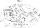
- FIG. 6is an enlarged sectional view illustrating a blade assembly of the cover unit.
- the brush drum unit 50may include a housing 54, a motor 56, a brush unit 51, a dust introduction detection unit 70 and a cover unit 80.
- the housing 54may be formed generally in a semi-cylindrical shape.
- the housing 54may be provided at the bottom thereof with a first opening 54a opened to a floor surface.
- a second opening 54b communicating with the dust box 60may be formed at the upper side of the first opening 54a.
- the dust introduction channel 50amay be a route which extended from the first opening 54a to the second opening 54b.
- the housing 54may be detachably mounted to the main body 11.
- a pivot arm 55may tilt the housing 54 with respect to the main body 11.
- the housing 54may move downward due to gravity when the autonomous cleaning device 10 travels on a smooth floor surface, for example, such as a wooden floor, exhibiting low frictional contact force with the brush unit 51, and the housing 54 may tilt upward when the autonomous cleaning device 10 travels on a floor surface, for example, such as a carpet, exhibiting high frictional contact force with the brush unit 51.
- the brush unit 51may be tilted upward, thereby reducing load applied to the motor 56.
- the motor 56may be mounted at the housing 54.
- the motor 56may supply power to the brush unit 51.
- the motor 56 and the brush unit 51may be connected to each other via a series of gears (not shown).
- the brush unit 51may be rotatably mounted to the housing 54.
- the brush unit 51may be rotated by power supplied from the motor 56.
- the dust introduction detection unit 70may determine whether or not dust is introduced into the dust introduction channel 50a of the housing 54 or an introduction amount of dust.
- the controllermay determine whether or not the autonomous cleaning device 10 is properly performing cleaning and which area is to be further cleaned through the operation of the dust introduction detection unit 70.
- the dust introduction detection unit 70may include a light emitting part 71 and a light receiving part 72.
- the light emitting part 71 and the light receiving part 72may be mounted at positions at opposite adjacent sides of the second opening 54b of the housing 54.
- the light emitting part 71 and the light receiving part 72may be mounted at positions at opposite adjacent sides of the introduction port 64 of the dust box 60 connected to the second opening 54b of the housing 54.
- the cover unit 80may be detachably mounted at the first opening 54a of the housing 54. A user may open the cover unit 80 to mount/separate the brush unit 51 to/from the housing 54.
- the cover unit 80may include a cover 81 and a blade assembly 82.
- the cover 81may have a size corresponding to the first opening 54a of the housing 54.
- the cover 81may be formed in a hollow shape, i.e. a shape having an outer edge and a hollow interior.
- the cover 81may be formed in a lattice shape. In this case, the lattice of the cover 81 may have a size appropriate to smoothly introduce dust.
- the blade assembly 82may be formed at one side of the cover 81.
- the blade assembly 82is mounted at the rear of the brush unit 51 to serve as a kind of dustpan when the brush unit 51 sweeps dust.
- the blade assembly 82may include a blade 83, a fixing member 84 and a support member 85.
- the fixing member 84 and the support member 85may be mounted so that the blade 83 exhibits proper rigidity and flexibility. As a result, a function of the blade 83 is improved to increase cleaning efficiency.
- the fixing member 84may be integrally formed at one side of the cover 81.
- the blade 83may be stacked below the fixing member 84, and the support member 85 may be stacked below the blade 83.
- the fixing member 84is provided with a protrusion 84a having a screw groove.
- the blade 83 and the support member 85have holes 83a and 85a through which the protrusion 84a of the fixing member 84 is inserted.
- the protrusion 84a of the fixing member 84is sequentially inserted through the hole 83a of the blade 83 and the hole 85a of the support member 85, and then a screw S is coupled to the protrusion 84a of the fixing member 84, thereby completing the blade assembly 82.
- the blade 83may be formed of a flexible material, for example, such as rubber, and may be mounted so as to be inclined downward toward a floor. At this time, the end of the blade 83 may come into tight contact with the floor.
- the blade 83may include a first part 91 and a second part 92 extended from the first part 91 toward the floor.
- the first part 91 of the blade 83is inclined downward.
- the first part 91 of the blade 83is tightly fixed by a first fixing part 84b of the fixing member 84 and a first support part 85b of the support member 85. That is, the first part 91 of the blade 83 is inserted and supported between the first fixing part 84b of the fixing member 84 and the first support part 85b of the support member 85, and therefore, the first part 91 of the blade 83 is prevented from moving.
- the second part 92 of the blade 83may include a moving portion 93 and a tight contact portion 94.
- the moving portion 93may be disposed horizontally, and the tight contact portion 94 may be inclined downward.
- the moving portion 93may have a predetermined inclination.
- a second fixing part 84c of the fixing member 84is provided adjacent to the upper side of the second part 92 of the blade 83. That is, the second fixing part 84c of the fixing member 84 is provided adjacent to the upper side of the moving portion 93 of the second part 92 of the blade 83.
- the second fixing part 84c of the fixing member 84pushes the moving portion 93 of the blade 83 downward so that the end of the tight contact portion 94 comes into tight contact with the floor. Also, upward movement of the moving portion 93 of the blade 83 is restricted, thereby preventing the end of the tight contact portion 94 from moving off of the floor.
- a second support part 85c of the support member 85is provided adjacent to the lower side of the second part 92 of the blade 83. That is, the second support part 85c of the support member 85 may include a first movement restriction portion 85d and a second movement restriction portion 85e corresponding to the moving portion 93 and the tight contact portion 94 of the second part 92 of the blade 83.
- the first movement restriction portion 85d of the support member 85is provided adjacent to the moving portion 93 of the blade 83, and the second movement restriction portion 85e of the support member 85 is also provided adjacent to the tight contact portion 94 of the blade 83.
- the moving portion 93 of the blade 83is provided between the second fixing part 84c of the fixing member 84 and the second support part 85c of the support member 85.
- the thickness t of the moving portion 93 of the blade 83is less than the distance T between the second fixing part 84c and the second support part 85c.
- the second support part 85c of the support member 85may be spaced apart from at least a portion of the moving portion 93 of the blade 83 by a predetermined distance.
- the second support part 85cis spaced apart from a boundary between the moving portion 93 and the tight contact portion 94, i.e. the end of the moving portion 93, by a predetermined distance T-t.
- the second part 92 of the blade 83may move between the second fixing part 84c of the fixing member 84 and the second support part 85c of the support member 85 within a predetermined range.
- the second support part 85c of the support member 85prevents the second part 92 of the blade 83 from being bent in the direction opposite to the travel direction of the main body 11, thereby securing operational reliability of the blade 83.
- a plurality of contact portions 95may be formed at the end of the second part 92 of the blade 83.
- the contact portions 95may be spaced apart from each other and may in contact with the floor. Consequently, the end of the blade 83 comes into surface contact with the floor through the contact portions 95.
- each of the contact portions 95may be formed in a quadrangular shape in section.
- a first contact portion 95a(see FIG. 7 ) may be formed in a wedge shape to increase contact area between the first contact portion and the floor.
- guides 84d and 94a of the blade assembly 82may be formed to coincide with the rotational arc of the brush unit 51. That is, the first guides 84d of the fixing member 84 and the second guides 94a of the blade 83 may be smoothly connected to each other, and the first guides 84d and the second guides 94a may coincide with the rotational arc of the brush unit 51. As a result, the guides 84d and 94a of the blade assembly 82 may enable the brush unit 51 to easily suction dust.
- the guides 84d and 94a of the blade assembly 82may not coincide with the rotational arc of the brush unit 51 but may be formed in various shapes, for example, such as a straight line or a curved line.
- FIG. 7is a view illustrating the operation of the blade assembly when the autonomous cleaning device according to the embodiment travels on a smooth floor
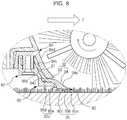
- FIG. 8is a view illustrating the operation of the blade assembly when the autonomous cleaning device travels on a floor, for example, such as a carpet, exhibiting high frictional contact force
- FIG. 9is a view illustrating the operation of the blade assembly when the autonomous cleaning device according to the embodiment travels on a floor having a crevice.
- the autonomous cleaning device 10may travel on a smooth floor.
- frictional force between the blade assembly 82 and the floormay be relatively small.
- the second part 92 of the blade 83is lowered due to gravity.
- the moving portion 93 of the second part 92is pushed downward by the second fixing part 84c of the fixing member 84. Consequently, the autonomous cleaning device 10 may travel in a state in which the contact portions 95 of the blade 83 are in tight contact with the floor.
- the end of the blade 83is prevented from moving off of the floor, and therefore, the brush unit 51 may more efficiently sweep dust into the dust box 60.
- the moving portion 93 of the second part 92 of the blade 83may move between the second fixing part 84c of the fixing member 84 and the second support part 85c of the support member 85 within a predetermined range, and therefore, the second part 92 of the blade 83 may exhibit a certain degree of flexibility.
- no memberis mounted at the upper side of the tight contact portion 94 of the second part 92 of the blade 83.
- the tight contact portion 94 of the second part 92 of the blade 83may exhibit flexibility due to the flexible material property thereof.
- the autonomous cleaning device 10may travel on a coarse floor, for example such as a carpet.
- frictional force between the blade assembly 82 and the floormay be relatively large.
- forceis applied to the second part 92 of the blade in the direction opposite to the direction of travel.
- the second support part 85c of the support member 85may prevent the second part 92 of the blade 83 from being bent in the direction opposite to the direction of travel. Consequently, the shape of the blade 83 is maintained and the function of the blade 83 is also maintained.
- the support member 85restricts the movement of the blade 83 to within a predetermined range, and therefore, the blade 83 may perform cleaning in a state in which the rigidity of the blade 83 is maintained to some extent.
- the autonomous cleaning device 10may travel over a floor having a crevice.
- the horizontal state of the contact portions 95 formed at the end of the blade 83may be maintained when the blade 83 passes over the crevice formed in the floor.
- a first contact portion 95a disposed at the front endpasses over the crevice
- a second contact portion 95b and a third contact portion 95c disposed at the rear endcome into tight contact with the floor with the result that the first contact portion 95a does not fall into the crevice.
- the second contact portion 95b and the third contact portion 95care supported by the floor, the horizontal state of the first contact portion 95a, the second contact portion 95b and the third contact portion 95c is maintained, and therefore, the first contact portion 95a does not fall into the crevice.
- the same conditionsmay be applied when the second contact portion 95b or the third contact portion 95c passes over the crevice. Consequently, any one of the contact portions 95 does not fall into the crevice, and therefore, abnormal noise or abnormal operation, which may be caused when the end of the blade 83 falls into the crevice or is caught by the crevice during travel, may be prevented.
- the cleaning function and the travelling function of the autonomous cleaning device 10may be secured based on this structure.
- FIG. 10Ais a bottom exploded view illustrating a cover unit according to an embodiment
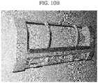
- FIG. 10Bis a photograph illustrating the cover unit according to the embodiment.
- FIGS. 11 and 12are views illustrating the operation of a blade assembly when the autonomous cleaning device according to the embodiment travels on a tatami (straw-mat) floor.
- a blade assembly 282may include a blade 283, a fixing member 284 and a support member 285.
- the fixing member 284 and the support member 285may be mounted so that the blade 283 exhibits proper rigidity and flexibility.
- the blade assembly 282will be described based on differences between the blade assembly 282 and the previously described blade assembly 82.
- the blade 283may includes a first part 291 constituting the upper part thereof and a second part 292 extended from the first part 291 toward a floor side.
- the first part 291is tightly fixed by a first fixing part 284b and a first support part 285b.
- the second part 292may include a moving portion 293 and a tight contact portion 294.
- the second part 292is moved between a second fixing part 284c and a second support part 285c. However, the movement of the second part 292 is restricted within a predetermined range, as previously described.
- the second part 292 of the blade 283is provided at the front thereof in a direction of travel with a first contact portion 295a protruding downward.
- the first contact portion 295amay be formed in a quadrangular shape in section.
- a first contact portion 295a'may be formed in a wedge shape in section to increase contact area with the first contact portion 295a' and a floor.
- guides 284d and 294a of the blade assembly 82are formed to coincide with the rotational arc of the brush unit 51 and the top of the first contact portion 295a' is formed to coincide with the rotational arc of the brush unit 51.
- the second part 292is provided at the rear end of the first contact portion 295a thereof in a direction of travel with a horizontality maintaining portion 296.
- the first contact portion 295aguides dust swept up by the brush unit 51 to the dust box 60 in a state in which the first contact portion 295a is in contact with a floor.
- a rugged tatami floor 500is cleaned as shown in the drawings, however, the first contact portion 295a falls into valleys 502 of the floor 500 and collides with ridges 501 of the floor 500 during traveling of the autonomous cleaning device 10.
- the first contact portion 295amay be damaged, the tatami floor 500 may be damaged, and noise may be generated.
- the horizontality maintaining portion 296is provided to prevent such damage and noise.
- the horizontality maintaining portion 296is formed to be wider than the width between neighboring ridges 501 of the tatami floor 500. Consequently, the horizontality maintaining portion 296 supports the first contact portion 295a so that the first contact portion 295a moves horizontally without falling into the valleys 502 of the tatami floor 500. For this reason, the horizontality maintaining portion 296 is formed at the end of the second part 292 with a width greater than the width between neighboring ridges 501 of the tatami floor 500. In the drawings, however, the horizontality maintaining portion 296 is shown as entirely covering the end of the second part 292 from the rear end of the first contact portion 295a.
- the first contact portion 295acontacts the floor. Consequently, the distance from the bottom of the first contact portion 295a to the floor is equal to or less than the distance from the bottom of the horizontality maintaining portion 296 to the floor. In the drawings, the distance from the bottom of the first contact portion 295a to the floor is shown as being equal to or less than the distance from the bottom of the horizontality maintaining portion 296 to the floor.
- the horizontality maintaining portion 296may be formed of a flexible material, such as a brush, rubber, sponge or fiber, to minimize damage to the tatami floor 500. Consequently, the first contact portion 295a as well as the second part 292 comes into tight contact with the floor by the horizontality maintaining portion 296.
- a photograph of a product in which the horizontality maintaining portion 296 is formed of a brushis shown in FIG. 10B . In the photograph, the brush is attached to the end of the blade.
- the horizontality maintaining portion 296may be formed of a material exhibiting frictional force lower than that of the first contact portion 295a since the horizontality maintaining portion 296 is provided to minimize damage to the tatami floor 500.
- the horizontality maintaining portion 296may serve as an auxiliary brush to collect residual dust which has not been swept up by the brush unit 51 so that the residual dust is easily swept up by the brush unit 51.
- the horizontality maintaining portion 296may not tightly contact the first contact portion 295a; however, the distance between the horizontality maintaining portion 296 and the first contact portion 295a is formed to be narrower than the width of each ridge 501 of the tatami floor 500. If the distance between the horizontality maintaining portion 296 and the first contact portion 295a is greater than the width of each ridge 501 of the tatami floor 500, the ridge 501 is inserted between the horizontality maintaining portion 296 and the first contact portion 295a with the result that noise may be generated, and the tatami floor 500 may be damaged.
- FIGS. 13 and 14are sectional views illustrating a blade assembly.
- a blade assembly 382may include a blade 383, a fixing member 384 and a support member 385.
- the fixing member 384 and the support member 385may be mounted so that the blade 383 exhibits proper rigidity and flexibility.
- the blade assembly 382will be described based on differences between the blade assembly 382 and the previously described blade assembly 82.
- a first part 391 of the blade 383is mounted in the horizontal direction and is tightly fixed by a first fixing part 384b of the fixing member 384 and a first support part 385b of the support member 385. That is, the first part 391 is inserted between the first fixing part 384b and the first support part 385b so that the first part 391 is pushed upward and downward, and therefore, the first part 391 is prevented from moving.
- a second part 392 of the blade 383is inclined.
- a second fixing part 384c of the fixing member 384is provided adjacent to the upper end of the second part 392 of the blade 383. The second fixing part 384c pushes the second part 392 of the blade 383 downward so that the lower end of the second part 392 comes into tight contact with a floor. Also, upward movement of the second part 392 of the blade 383 is restricted, thereby preventing the lower end of the second part 392 from moving off of the floor.
- a second support part 385c of the support member 385is provided adjacent to the lower side of the second part 392 of the blade 383.
- the second support part 385cis almost in contact with the upper part of the second part 392 of the blade 383 and is spaced apart from the lower part of the second part 392 of the blade 383 by a predetermined distance. That is, the distance between the second part 392 of the blade 383 and the second support part 385c increases from the upper side to the lower side of the part 392 of the blade 383 so that the second part 392 of the blade 383 exhibits proper flexibility and rigidity.
- the second part 392 of the blade 383may be moved by the second fixing part 384c and the second support part 385c within a predetermined range.
- the second support part 385cprevents the second part 392 of the blade 383 from being bent in the direction opposite to the travel direction of the main body 11, thereby securing operational reliability of the blade 383.
- a plurality of contact portions 395may be formed at the lower end of the second part 392 of the blade 383.
- a front one of the contact portions 395i.e. a first contact portion 395a, may be formed in a quadrangular or wedge shape in section.
- the second part 392 of the blade 383is provided at the front thereof in the travel direction of the autonomous cleaning device 10 with a first contact portion 395a protruding downward.
- the first contact portion 395amay be formed in a quadrangular or wedge shape in section.
- the second part 392is provided at the rear end of the first contact portion 395a thereof in a direction of travel with a horizontality maintaining portion 396.
- the horizontality maintaining portion 396supports the first contact portion 395a so that the first contact portion 395a moves horizontally without falling into valleys 502 of the tatami floor 500. Consequently, noise is reduced, and damage to the tatami floor 500 is prevented.
- the horizontality maintaining portion 396is formed to be wider than the width between neighboring ridges 501 of the tatami floor 500 so that the first contact portion 395a moves horizontally over the rugged tatami floor 500.
- the horizontality maintaining portion 396is shown as entirely covering the lower end of the second part 392.
- the first contact portion 395acontacts the floor. Consequently, the distance from the bottom of the first contact portion 2395a to the floor is equal to or less than the distance from the bottom of the horizontality maintaining portion 396 to the floor.
- the horizontality maintaining portion 396may be formed of a flexible material, such as a brush, rubber, sponge or fiber, to minimize damage to the tatami floor 500.
- FIGS. 13 and 14The operation of the blade assembly 382 shown in FIGS. 13 and 14 may be easily understood with reference to FIGS. 7 to 12 , and therefore, a description thereof will not be given.
- the blade of the autonomous cleaning deviceis prevented from becoming misaligned due to assembly tolerance or injection tolerance, and the blade is prevented from moving off of a floor, thereby improving cleaning performance.
- the bladeis prevented from being bent, thereby securing travel and cleaning performance of the autonomous cleaning device.
- the shape of the blade assemblyis approximated to the rotational arc of the brush, thereby improving cleaning performance of the autonomous cleaning device.
Landscapes
- Engineering & Computer Science (AREA)
- Mechanical Engineering (AREA)
- Nozzles For Electric Vacuum Cleaners (AREA)
- Electric Suction Cleaners (AREA)
- Electric Vacuum Cleaner (AREA)
Description
- Embodiments relate to an autonomous cleaning device wherein the structure of a blade assembly is improved, thereby improving cleaning efficiency.
- An autonomous mobile robot is a device that travels about an arbitrary area to perform a predetermined task without user manipulation. The robot may travel autonomously to a considerable extent, and autonomous travel may be embodied in various manners. For example, the robot may travel along a predetermined route using a map or may travel using a sensor to sense surroundings thereof without following a predetermined route.
- An autonomous cleaning device travels about an area to be cleaned so as to clean a floor without user manipulation. Specifically, the autonomous cleaning device may function to remove dust or clean a floor at home. Here, dust may include dirt, motes, powder, fragments and other dust particles.
- The autonomous cleaning device includes a brush unit to sweep up dust and a blade to guide the dust to a dust box. However, the distance between the blade and a floor is not adjusted. When the blade moves off of the floor, the dust is not properly guided, thereby lowering cleaning performance. When the blade comes into excessively tight contact with the floor, abnormal noise is generated.
WO 2005/077244 A1 discloses an autonomous cleaning device with the features of the pre-characterizing part of claim 1. This cleaning device comprises a main body with a brush unit and also a blade assembly as part of a dustbin. The blade assembly comprises a blade, which is said to be flexible and to be constructed of, for example, rubber. The flexible blade directs dirt collected by the brush of the cleaning device into the dustbin. It is also said that the flexible blade is directed from an upper edge of the dustbin to the surface below the cartridge.US 4,709,436 A discloses a dust sweeper which includes a debris pan with an inlet portion that glides on the surface being cleaned. The drbis pan is configured with an inlet portion or scoop for directing debris propelled by a rotary brush into the debris pan, The scoop portion corresponds to a blade assembly with a contact portion as a corresponding blade which extends towards the floor. This blade has a lower surface as a contact portion that contacts the floor.- It is an object of the present invention to provide an autonomous cleaning device having improved dust suction performance, that further secures travel performance and cleaning performance irrespective of a floor state.
- Additional aspects of the invention will be set forth in part in the description which follows and, in part, will be apparent from the description, or may be learned by practice of the invention.
- This object is solved by the features of the independent claims.
- Advantageous embodiments are disclosed by the subclaimed.
- The maintaining portion may be attached to a bottom surface of the blade.
- Furthermore, the maintaining portion may be disposed in a longitudinal direction of the blade.
- A width of the maintaining portion may be selected such that the contact portion can move across a tatami floor without the contact portion falling into valleys of the tatami floor.
- The blade may be adapted to bend downward when the contact portion establishes frictional contact with the floor.
- The maintaining portion can be formed of the material exhibiting frictional force lower than that of the contact portion.
- The blade may be formed of a rubber material and the maintaining portion is formed of a fiber material.
- The blade may also be formed of a rubber material and the maintaining portion is formed of a sponge material.
- The maintaining portion may serve to collect residual dust that has not been swept up by the brush unit.
- The support member may include a first support part to contact the first part of the blade and a second support part which is adjacent to the second part of the blade.
- The blade assembly may further include a fixing member having at least a portion disposed adjacent to the second part of the blade so that an end of the second part of the blade remains in tight contact with the floor.
- The fixing member may include a first fixing part to contact the first part of the blade and a second fixing part which is adjacent to the second part of the blade.
- The second part of the blade may include at least one moving portion, the second support part of the support member may be disposed adjacent to a lower side of the at least one moving portion, and the second fixing part of the fixing member may be disposed adjacent to an upper side of the at least one moving portion.
- The distance between the second support part of the support member and the second fixing part of the fixing member may be greater than a thickness of the second part of the blade.
- The second part of the blade may include a moving portion and a tight contact portion extended from the moving portion toward the floor, and the second support part of the support member may include a first movement restriction portion corresponding to the moving portion and a second movement restriction portion corresponding to the tight contact portion.
- The second part of the blade may include a moving portion and a tight contact portion extended from the moving portion toward the floor, and the fixing member may include at least one guide smoothly connected to a guide of the tight contact portion.
- The guide of the tight contact portion and the at least one guide of the fixing member may coincide with a rotational arc of the brush unit.
- The second part of the blade may include a plurality of contact portions in tight contact with the floor, and the contact portions may simultaneously be in tight contact with the floor.
- When at least one of the contact portions is positioned above a crevice of the floor, the remaining contact portions may support the at least one of the contact portions so that the at least one of the contact portions does not fall into the crevice.
- A front one of the contact portions in a direction of travel may be formed in a quadrangular or wedge shape in section.
- Each of the contact portions may include a first contact portion formed at the front end of the second part in a direction of travel so that the first contact portion protrudes downward and said horizontality maintaining portion to support the first contact portion so that the first contact portion is maintained horizontal even over a rugged floor.
- The horizontality maintaining portion may be formed to cover the end of the second part at the rear of the first contact portion.
- The distance from the bottom of the first contact portion to the floor may be equal to or less than the distance from the bottom of the horizontality maintaining portion to the floor.
- The horizontality maintaining portion may be formed of a flexible material.
- When at least one of the contact portions is positioned above a crevice of the floor, the remaining contact portions may support the at least one of the contact portions so that the at least one of the contact portions does not fall into the crevice.
- The second part of the blade may include a first contact portion configured to tightly contact the floor and a second contact portion provided at a rear end of the first contact portion in a direction of travel to support the first contact portion so that the first contact portion does not fall into valleys of a rugged floor.
- The autonomous cleaning device may further include a fixing member and a support member disposed adjacent to an upper side and a lower side of the blade to restrict movement of the blade to within a predetermined range.
- The thickness of the blade may be less than the distance between the fixing member and the support member.
- The blade assembly may further include a support member spaced apart from the second part of the blade to prevent the second part of the blade from being bent in a direction opposite to a direction of travel.
- The second part of the blade may include at least one moving portion and at least one tight contact portion extended from the at least one moving portion toward the floor, and the support member may include at least one first movement restriction portion and at least one second movement restriction portion corresponding to the second part of the blade.
- The blade assembly may further include a plurality of contact portions formed at the second part of the blade so that the contact portions are in tight contact with the floor, and, when at least one of the contact portions is positioned above a crevice of the floor, the remaining contact portions may support the at least one of the contact portions so that the at least one of the contact portions does not fall into the crevice.
- The autonomous cleaning device may further include a plurality of contact portions formed at the second part of the blade so that the contact portions contact the floor, wherein each of the contact portions may include a first contact portion formed at a front of an end of the blade in a direction of travel so as to protrude downward so that the first contact portion tightly contacts the floor and a second contact portion provided at the rear end of the first contact portion in a direction of travel to support the first contact portion so that the first contact portion does not fall into valleys of a rugged floor.
- The fixing member and the support member may restrict movement of the second part of the blade to within a predetermined range.
- The blade may further include a plurality of contact portions provided at an end of the second part so that the contact portions contact the floor.
- These and/or other aspects will become apparent and more readily appreciated from the following description of the embodiments, taken in conjunction with the accompanying drawings of which:
FIG. 1 is a perspective view illustrating an autonomous cleaning device according to an embodiment;FIG. 2 is a sectional view illustrating the autonomous cleaning device;FIG. 3 is a bottom perspective view illustrating the autonomous cleaning device;FIG. 4 is an exploded perspective view illustrating a brush drum unit;FIG. 5 is an exploded bottom perspective view illustrating a cover unit;FIG. 6 is an enlarged sectional view illustrating a blade assembly of the cover unit;FIG. 7 is a view illustrating the operation of the blade assembly when the autonomous cleaning device travels on a smooth floor;FIG. 8 is a view illustrating the operation of the blade assembly when the autonomous cleaning device travels on a floor, such as a carpet, exhibiting high frictional contact force;FIG. 9 is a view illustrating the operation of the blade assembly when the autonomous cleaning device travels on a floor having a crevice;FIG. 10A is a bottom exploded view illustrating a cover unit according to an embodiment;FIG. 10B is a photograph illustrating the cover unit according to the embodiment;FIGS. 11 and12 are views illustrating the operation of a blade assembly when the autonomous cleaning device according to the embodiment travels on a tatami (straw-mat) floor; andFIGS. 13 and14 are sectional views illustrating a blade assembly.- Reference will now be made in detail to the embodiments, examples of which are illustrated in the accompanying drawings, wherein like reference numerals refer to like elements throughout.
FIG. 1 is a perspective view illustrating an autonomous cleaning device according to an embodiment,FIG. 2 is a sectional view illustrating the autonomous cleaning device, andFIG. 3 is a bottom perspective view illustrating the autonomous cleaning device.- As shown in
FIGS. 1 to 3 , anautonomous cleaning device 10 may include amain body 11, adrive unit 20, acleaning unit 30 and a controller (not shown). - The
main body 11 may be configured in various forms. For example, themain body 11 may be configured in a circular form. The circularmain body 11 has a uniform radius of rotation, and therefore, themain body 11 may avoid contact with surrounding obstacles and may easily change course. Also, during travel, themain body 11 may be prevented from being caught by surrounding obstacles. - Various components, for example such as the
drive unit 20, thecleaning unit 30,various sensors display unit 14, and the controller (not show), to perform cleaning may be provided at themain body 11. - The
drive unit 20 may enable themain body 11 to travel about an area to be cleaned. Thedrive unit 20 may include left andright drive wheels caster 22. Power from a motor (not shown) may be supplied to the left andright drive wheels right drive wheels main body 11 and thecaster 22 may be mounted at the front region of the bottom of themain body 11 so that the main body maintains a stable posture. - Meanwhile, the left and
right drive wheels caster 22 may constitute a single assembly, which may be detachably mounted to themain body 11. - The
cleaning unit 30 may remove dust from a floor on which themain body 11 is positioned and surroundings thereof. Thecleaning unit 30 may include aside brush 40, abrush drum unit 50 and adust box 60. - The
side brush 40 may be rotatably mounted at one side of the edge of the bottom of themain body 11. Theside brush 40 may deviate from the middle region of the main body with an inclination to the front F of themain body 11. - The
side brush 40 may move dust collected around themain body 11 to a floor where themain body 11 is positioned. Theside brush 40 may extend a cleaning range to an area around a floor where themain body 11 is positioned. In particular, theside brush 40 may remove dust collected from a corner, which is a boundary between a floor and walls. - The
brush drum unit 50 may be mounted at a position deviating from the middle region of the bottom of themain body 11. Thebrush drum unit 50 may deviate from the left andright drive wheels main body 11 toward the rear R of themain body 11. - The
brush drum unit 50 may remove dust collected on a floor where themain body 11 is positioned. Thebrush drum unit 50 may include adust introduction channel 50a forming a dust introduction route. Also, thebrush drum unit 50 may include abrush unit 51 provided in thedust introduction channel 50a to sweep dust off of the floor. - The
brush unit 51 may include aroller 51a and abrush 51b formed at the outer circumference of the roller 51a. Power from a motor 56 (seeFIG. 4 ) may be supplied to theroller 51a. Through rotation of theroller 51a, thebrush 51b may sweep up dust collected on the floor. Theroller 51a may be formed of a rigid body, to which, however, theroller 51a is not limited. Thebrush 51b may be formed of various materials exhibiting high elasticity. - The
brush unit 51 may be driven at uniform speed to maintain uniform cleaning performance. When a floor surface that is not smooth, for example, such as a carpet, is cleaned, the rotational speed of thecrush unit 51 may be lower than the rotational speed of thebrush unit 51 when a smooth floor surface is cleaned. At this time, additional current may be supplied to ensure that thebrush unit 51 maintain a uniform rotational speed. - The
dust box 60 may be mounted at the rear R of themain body 11. Anintroduction port 64 of thedust box 60 may communicate with thedust introduction channel 50a of thebrush drum unit 50. Consequently, dust swept by thebrush unit 51 may be stored in thedust box 60 via thedust introduction channel 50a. - The
dust box 60 may be divided into alarge dust box 61 and asmall dust box 62 by apartition 63. Correspondingly, theintroduction port 64 may be divided into afirst introduction port 64a provided at an inlet of thelarge dust box 61 and asecond introduction port 64b provided at an inlet of thesmall dust box 62. - The
brush unit 51 may sweep relatively large dust particles into thelarge dust box 61. A blowingunit 52 may suction relatively small airborne dust, such as hair, into thesmall dust box 62. In particular, abrush cleaning member 59 may be provided at a position adjacent to thesecond introduction port 64b to separate hair from thebrush unit 51. The hair separated from thebrush unit 51 by thebrush cleaning member 59 may be stored in thesmall dust box 62 by suction force of the blowingunit 52. - Also, a dust
amount detection unit 65 may be provided in thedust box 60 to detect whether thedust box 60 is filled with dust. The dustamount detection unit 65 may include alight emitting part 65a to emit a beam and alight receiving part 65b to receive the beam. When an amount of light received by thelight receiving part 65b is equal to or less than a predetermined value, it may be determined that thedust box 60 is filled with dust. - Meanwhile, the
brush drum unit 50, thebrush unit 51 and thedust box 60 may constitute a single assembly, which may be detachably mounted to themain body 11. - The
sensors proximity sensor 12 and/or anoptical sensor 13. For example, when theautonomous cleaning device 10 travels in an arbitrary direction without a predetermined route, i.e. in a cleaning system not employing a map, theautonomous cleaning device 10 may travels about an area to be cleaned using theproximity sensor 12. On the other hand, when theautonomous cleaning device 10 travels along a predetermined route, i.e. in a cleaning system having a map, theoptical sensor 13 may be provided to receive position information of theautonomous cleaning device 10 and create a map. Theoptical sensor 13 corresponds to an embodiment of a location system. Other various methods may be provided. - The
display unit 14 may display various states of theautonomous cleaning device 10. For example, thedisplay unit 14 may display a battery charge state, whether thedust box 60 is filled with dust, and a cleaning mode or a resting mode of theautonomous cleaning device 10. - The controller (not shown) may control the
drive unit 20 and thecleaning unit 30 to efficiently perform a cleaning task. The controller may receive signals from thesensors
Also, the controller may receive a signal from the dustamount detection unit 65. Upon determining that thedust box 60 is filled with dust, the controller may dock with a maintenance station (not shown) to automatically remove dust from thedust box 60 or may sound an alarm to notify a user. - Also, the controller may receive a signal from a dust
introduction detection unit 70 to distinguish between an area from which dust is introduced and an area from which dust is not introduced. For example, an area may be traveled over repeatedly, a travel speed may be reduced or rotational force of thebrush unit 51 or the suction force of the blowingunit 52 may be increased to improve cleaning efficiency at an area from which dust is introduced. On the other hand, a cleaning sequence may be delayed or the number of times of travel may be reduced at an area from which dust is not introduced. FIG. 4 is an exploded perspective view illustrating a brush drum unit,FIG. 5 is an exploded bottom perspective view illustrating a cover unit, andFIG. 6 is an enlarged sectional view illustrating a blade assembly of the cover unit.- As shown in
FIGS. 1 to 6 , thebrush drum unit 50 may include ahousing 54, amotor 56, abrush unit 51, a dustintroduction detection unit 70 and acover unit 80. - The
housing 54 may be formed generally in a semi-cylindrical shape. Thehousing 54 may be provided at the bottom thereof with afirst opening 54a opened to a floor surface. Asecond opening 54b communicating with thedust box 60 may be formed at the upper side of thefirst opening 54a. Thedust introduction channel 50a may be a route which extended from thefirst opening 54a to thesecond opening 54b. - The
housing 54 may be detachably mounted to themain body 11. In particular, apivot arm 55 may tilt thehousing 54 with respect to themain body 11. Through this structure, thehousing 54 may move downward due to gravity when theautonomous cleaning device 10 travels on a smooth floor surface, for example, such as a wooden floor, exhibiting low frictional contact force with thebrush unit 51, and thehousing 54 may tilt upward when theautonomous cleaning device 10 travels on a floor surface, for example, such as a carpet, exhibiting high frictional contact force with thebrush unit 51. At this time, thebrush unit 51 may be tilted upward, thereby reducing load applied to themotor 56. - The
motor 56 may be mounted at thehousing 54. Themotor 56 may supply power to thebrush unit 51. For example, themotor 56 and thebrush unit 51 may be connected to each other via a series of gears (not shown). - The
brush unit 51 may be rotatably mounted to thehousing 54. Thebrush unit 51 may be rotated by power supplied from themotor 56. - The dust
introduction detection unit 70 may determine whether or not dust is introduced into thedust introduction channel 50a of thehousing 54 or an introduction amount of dust. The controller may determine whether or not theautonomous cleaning device 10 is properly performing cleaning and which area is to be further cleaned through the operation of the dustintroduction detection unit 70. - The dust
introduction detection unit 70 may include alight emitting part 71 and alight receiving part 72. Thelight emitting part 71 and thelight receiving part 72 may be mounted at positions at opposite adjacent sides of thesecond opening 54b of thehousing 54. In another embodiment, thelight emitting part 71 and thelight receiving part 72 may be mounted at positions at opposite adjacent sides of theintroduction port 64 of thedust box 60 connected to thesecond opening 54b of thehousing 54. - The
cover unit 80 may be detachably mounted at thefirst opening 54a of thehousing 54. A user may open thecover unit 80 to mount/separate thebrush unit 51 to/from thehousing 54. - The
cover unit 80 may include acover 81 and ablade assembly 82. - The
cover 81 may have a size corresponding to thefirst opening 54a of thehousing 54. Thecover 81 may be formed in a hollow shape, i.e. a shape having an outer edge and a hollow interior. In another embodiment, thecover 81 may be formed in a lattice shape. In this case, the lattice of thecover 81 may have a size appropriate to smoothly introduce dust. - The
blade assembly 82 may be formed at one side of thecover 81. In particular, theblade assembly 82 is mounted at the rear of thebrush unit 51 to serve as a kind of dustpan when thebrush unit 51 sweeps dust. - The
blade assembly 82 may include ablade 83, a fixingmember 84 and asupport member 85. The fixingmember 84 and thesupport member 85 may be mounted so that theblade 83 exhibits proper rigidity and flexibility. As a result, a function of theblade 83 is improved to increase cleaning efficiency. - The fixing
member 84 may be integrally formed at one side of thecover 81. Theblade 83 may be stacked below the fixingmember 84, and thesupport member 85 may be stacked below theblade 83. The fixingmember 84 is provided with aprotrusion 84a having a screw groove. Theblade 83 and thesupport member 85 haveholes protrusion 84a of the fixingmember 84 is inserted. Theprotrusion 84a of the fixingmember 84 is sequentially inserted through thehole 83a of theblade 83 and thehole 85a of thesupport member 85, and then a screw S is coupled to theprotrusion 84a of the fixingmember 84, thereby completing theblade assembly 82. - The
blade 83 may be formed of a flexible material, for example, such as rubber, and may be mounted so as to be inclined downward toward a floor. At this time, the end of theblade 83 may come into tight contact with the floor. - The
blade 83 may include afirst part 91 and asecond part 92 extended from thefirst part 91 toward the floor. - The
first part 91 of theblade 83 is inclined downward. Thefirst part 91 of theblade 83 is tightly fixed by afirst fixing part 84b of the fixingmember 84 and afirst support part 85b of thesupport member 85. That is, thefirst part 91 of theblade 83 is inserted and supported between the first fixingpart 84b of the fixingmember 84 and thefirst support part 85b of thesupport member 85, and therefore, thefirst part 91 of theblade 83 is prevented from moving. - The
second part 92 of theblade 83 may include a movingportion 93 and atight contact portion 94. As shown in the drawings, the movingportion 93 may be disposed horizontally, and thetight contact portion 94 may be inclined downward. In another embodiment, the movingportion 93 may have a predetermined inclination. - A
second fixing part 84c of the fixingmember 84 is provided adjacent to the upper side of thesecond part 92 of theblade 83. That is, the second fixingpart 84c of the fixingmember 84 is provided adjacent to the upper side of the movingportion 93 of thesecond part 92 of theblade 83. Thesecond fixing part 84c of the fixingmember 84 pushes the movingportion 93 of theblade 83 downward so that the end of thetight contact portion 94 comes into tight contact with the floor. Also, upward movement of the movingportion 93 of theblade 83 is restricted, thereby preventing the end of thetight contact portion 94 from moving off of the floor. - A
second support part 85c of thesupport member 85 is provided adjacent to the lower side of thesecond part 92 of theblade 83. That is, thesecond support part 85c of thesupport member 85 may include a firstmovement restriction portion 85d and a secondmovement restriction portion 85e corresponding to the movingportion 93 and thetight contact portion 94 of thesecond part 92 of theblade 83. The firstmovement restriction portion 85d of thesupport member 85 is provided adjacent to the movingportion 93 of theblade 83, and the secondmovement restriction portion 85e of thesupport member 85 is also provided adjacent to thetight contact portion 94 of theblade 83. - In other words, the moving
portion 93 of theblade 83 is provided between the second fixingpart 84c of the fixingmember 84 and thesecond support part 85c of thesupport member 85. The thickness t of the movingportion 93 of theblade 83 is less than the distance T between the second fixingpart 84c and thesecond support part 85c. When the movingportion 93 of theblade 83 completely contacts the second fixingpart 84c of the fixingmember 84, thesecond support part 85c of thesupport member 85 may be spaced apart from at least a portion of the movingportion 93 of theblade 83 by a predetermined distance. In particular, thesecond support part 85c is spaced apart from a boundary between the movingportion 93 and thetight contact portion 94, i.e. the end of the movingportion 93, by a predetermined distance T-t. - The
second part 92 of theblade 83 may move between the second fixingpart 84c of the fixingmember 84 and thesecond support part 85c of thesupport member 85 within a predetermined range. In particular, thesecond support part 85c of thesupport member 85 prevents thesecond part 92 of theblade 83 from being bent in the direction opposite to the travel direction of themain body 11, thereby securing operational reliability of theblade 83. - A plurality of
contact portions 95 may be formed at the end of thesecond part 92 of theblade 83. Thecontact portions 95 may be spaced apart from each other and may in contact with the floor. Consequently, the end of theblade 83 comes into surface contact with the floor through thecontact portions 95. Here, each of thecontact portions 95 may be formed in a quadrangular shape in section. In another embodiment, afirst contact portion 95a (seeFIG. 7 ) may be formed in a wedge shape to increase contact area between the first contact portion and the floor. - Meanwhile, guides 84d and 94a of the
blade assembly 82 may be formed to coincide with the rotational arc of thebrush unit 51. That is, thefirst guides 84d of the fixingmember 84 and thesecond guides 94a of theblade 83 may be smoothly connected to each other, and thefirst guides 84d and thesecond guides 94a may coincide with the rotational arc of thebrush unit 51. As a result, theguides blade assembly 82 may enable thebrush unit 51 to easily suction dust. In another embodiment, theguides blade assembly 82 may not coincide with the rotational arc of thebrush unit 51 but may be formed in various shapes, for example, such as a straight line or a curved line. - Hereinafter, the operation of the autonomous cleaning device will be described with reference to the accompanying drawings.
FIG. 7 is a view illustrating the operation of the blade assembly when the autonomous cleaning device according to the embodiment travels on a smooth floor,FIG. 8 is a view illustrating the operation of the blade assembly when the autonomous cleaning device travels on a floor, for example, such as a carpet, exhibiting high frictional contact force, andFIG. 9 is a view illustrating the operation of the blade assembly when the autonomous cleaning device according to the embodiment travels on a floor having a crevice.- As shown in
FIG. 7 , theautonomous cleaning device 10 may travel on a smooth floor. In this case, frictional force between theblade assembly 82 and the floor may be relatively small. At this time, thesecond part 92 of theblade 83 is lowered due to gravity. In particular, the movingportion 93 of thesecond part 92 is pushed downward by the second fixingpart 84c of the fixingmember 84. Consequently, theautonomous cleaning device 10 may travel in a state in which thecontact portions 95 of theblade 83 are in tight contact with the floor. As a result, the end of theblade 83 is prevented from moving off of the floor, and therefore, thebrush unit 51 may more efficiently sweep dust into thedust box 60. - Also, the moving
portion 93 of thesecond part 92 of theblade 83 may move between the second fixingpart 84c of the fixingmember 84 and thesecond support part 85c of thesupport member 85 within a predetermined range, and therefore, thesecond part 92 of theblade 83 may exhibit a certain degree of flexibility. In addition, no member is mounted at the upper side of thetight contact portion 94 of thesecond part 92 of theblade 83. Thetight contact portion 94 of thesecond part 92 of theblade 83 may exhibit flexibility due to the flexible material property thereof. - Also, as shown in
FIG. 8 , theautonomous cleaning device 10 may travel on a coarse floor, for example such as a carpet. In this case, frictional force between theblade assembly 82 and the floor may be relatively large. As a result, force is applied to thesecond part 92 of the blade in the direction opposite to the direction of travel. At this time, thesecond support part 85c of thesupport member 85 may prevent thesecond part 92 of theblade 83 from being bent in the direction opposite to the direction of travel. Consequently, the shape of theblade 83 is maintained and the function of theblade 83 is also maintained. In this way, thesupport member 85 restricts the movement of theblade 83 to within a predetermined range, and therefore, theblade 83 may perform cleaning in a state in which the rigidity of theblade 83 is maintained to some extent. - Also, as shown in
FIG. 9 , theautonomous cleaning device 10 may travel over a floor having a crevice. In this case, the horizontal state of thecontact portions 95 formed at the end of theblade 83 may be maintained when theblade 83 passes over the crevice formed in the floor. For example, when afirst contact portion 95a disposed at the front end passes over the crevice, asecond contact portion 95b and athird contact portion 95c disposed at the rear end come into tight contact with the floor with the result that thefirst contact portion 95a does not fall into the crevice. That is, since thesecond contact portion 95b and thethird contact portion 95c are supported by the floor, the horizontal state of thefirst contact portion 95a, thesecond contact portion 95b and thethird contact portion 95c is maintained, and therefore, thefirst contact portion 95a does not fall into the crevice. The same conditions may be applied when thesecond contact portion 95b or thethird contact portion 95c passes over the crevice. Consequently, any one of thecontact portions 95 does not fall into the crevice, and therefore, abnormal noise or abnormal operation, which may be caused when the end of theblade 83 falls into the crevice or is caught by the crevice during travel, may be prevented. The cleaning function and the travelling function of theautonomous cleaning device 10 may be secured based on this structure. FIG. 10A is a bottom exploded view illustrating a cover unit according to an embodiment, andFIG. 10B is a photograph illustrating the cover unit according to the embodiment.FIGS. 11 and12 are views illustrating the operation of a blade assembly when the autonomous cleaning device according to the embodiment travels on a tatami (straw-mat) floor.- As shown in
FIGS. 10A to 12 , ablade assembly 282 may include ablade 283, a fixingmember 284 and asupport member 285. The fixingmember 284 and thesupport member 285 may be mounted so that theblade 283 exhibits proper rigidity and flexibility. Hereinafter, theblade assembly 282 will be described based on differences between theblade assembly 282 and the previously describedblade assembly 82. - The
blade 283 may includes afirst part 291 constituting the upper part thereof and asecond part 292 extended from thefirst part 291 toward a floor side. - The
first part 291 is tightly fixed by afirst fixing part 284b and afirst support part 285b. - The
second part 292 may include a movingportion 293 and atight contact portion 294. Thesecond part 292 is moved between asecond fixing part 284c and asecond support part 285c. However, the movement of thesecond part 292 is restricted within a predetermined range, as previously described. - The
second part 292 of theblade 283 is provided at the front thereof in a direction of travel with afirst contact portion 295a protruding downward. Thefirst contact portion 295a may be formed in a quadrangular shape in section. - In another embodiment, a
first contact portion 295a' (seeFIG. 12 ) may be formed in a wedge shape in section to increase contact area with thefirst contact portion 295a' and a floor. In addition, guides 284d and 294a of theblade assembly 82 are formed to coincide with the rotational arc of thebrush unit 51 and the top of thefirst contact portion 295a' is formed to coincide with the rotational arc of thebrush unit 51. As a result,
suction of dust through thebrush unit 51 is easily achieved. - The
second part 292 is provided at the rear end of thefirst contact portion 295a thereof in a direction of travel with ahorizontality maintaining portion 296. - The
first contact portion 295a guides dust swept up by thebrush unit 51 to thedust box 60 in a state in which thefirst contact portion 295a is in contact with a floor. When arugged tatami floor 500 is cleaned as shown in the drawings, however, thefirst contact portion 295a falls intovalleys 502 of thefloor 500 and collides withridges 501 of thefloor 500 during traveling of theautonomous cleaning device 10. As a result, thefirst contact portion 295a may be damaged, thetatami floor 500 may be damaged, and noise may be generated. Thehorizontality maintaining portion 296 is provided to prevent such damage and noise. - The
horizontality maintaining portion 296 is formed to be wider than the width between neighboringridges 501 of thetatami floor 500. Consequently, thehorizontality maintaining portion 296 supports thefirst contact portion 295a so that thefirst contact portion 295a moves horizontally without falling into thevalleys 502 of thetatami floor 500. For this reason, thehorizontality maintaining portion 296 is formed at the end of thesecond part 292 with a width greater than the width between neighboringridges 501 of thetatami floor 500. In the drawings, however, thehorizontality maintaining portion 296 is shown as entirely covering the end of thesecond part 292 from the rear end of thefirst contact portion 295a. - The
first contact portion 295a contacts the floor. Consequently, the distance from the bottom of thefirst contact portion 295a to the floor is equal to or less than the distance from the bottom of thehorizontality maintaining portion 296 to the floor. In the drawings, the distance from the bottom of thefirst contact portion 295a to the floor is shown as being equal to or less than the distance from the bottom of thehorizontality maintaining portion 296 to the floor. - The
horizontality maintaining portion 296 may be formed of a flexible material, such as a brush, rubber, sponge or fiber, to minimize damage to thetatami floor 500. Consequently, thefirst contact portion 295a as well as thesecond part 292 comes into tight contact with the floor by thehorizontality maintaining portion 296.
A photograph of a product in which thehorizontality maintaining portion 296 is formed of a brush is shown inFIG. 10B . In the photograph, the brush is attached to the end of the blade. - Meanwhile, the
horizontality maintaining portion 296 may be formed of a material exhibiting frictional force lower than that of thefirst contact portion 295a since thehorizontality maintaining portion 296 is provided to minimize damage to thetatami floor 500. - The
horizontality maintaining portion 296 may serve as an auxiliary brush to collect residual dust which has not been swept up by thebrush unit 51 so that the residual dust is easily swept up by thebrush unit 51. - The
horizontality maintaining portion 296 may not tightly contact thefirst contact portion 295a; however, the distance between thehorizontality maintaining portion 296 and thefirst contact portion 295a is formed to be narrower than the width of eachridge 501 of thetatami floor 500. If the distance between thehorizontality maintaining portion 296 and thefirst contact portion 295a is greater than the width of eachridge 501 of thetatami floor 500, theridge 501 is inserted between thehorizontality maintaining portion 296 and thefirst contact portion 295a with the result that noise may be generated, and thetatami floor 500 may be damaged. FIGS. 13 and14 are sectional views illustrating a blade assembly.- As shown in
FIGS. 13 and14 , ablade assembly 382 may include ablade 383, a fixingmember 384 and asupport member 385. The fixingmember 384 and thesupport member 385 may be mounted so that theblade 383 exhibits proper rigidity and flexibility. Hereinafter, theblade assembly 382 will be described based on differences between theblade assembly 382 and the previously describedblade assembly 82. - A
first part 391 of theblade 383 is mounted in the horizontal direction and is tightly fixed by afirst fixing part 384b of the fixingmember 384 and afirst support part 385b of thesupport member 385. That is, thefirst part 391 is inserted between the first fixingpart 384b and thefirst support part 385b so that thefirst part 391 is pushed upward and downward, and therefore, thefirst part 391 is prevented from moving.
Asecond part 392 of theblade 383 is inclined. Asecond fixing part 384c of the fixingmember 384 is provided adjacent to the upper end of thesecond part 392 of theblade 383. Thesecond fixing part 384c pushes thesecond part 392 of theblade 383 downward so that the lower end of thesecond part 392 comes into tight contact with a floor. Also, upward movement of thesecond part 392 of theblade 383 is restricted, thereby preventing the lower end of thesecond part 392 from moving off of the floor. - A
second support part 385c of thesupport member 385 is provided adjacent to the lower side of thesecond part 392 of theblade 383. Thesecond support part 385c is almost in contact with the upper part of thesecond part 392 of theblade 383 and is spaced apart from the lower part of thesecond part 392 of theblade 383 by a predetermined distance. That is, the distance between thesecond part 392 of theblade 383 and thesecond support part 385c increases from the upper side to the lower side of thepart 392 of theblade 383 so that thesecond part 392 of theblade 383 exhibits proper flexibility and rigidity. - The
second part 392 of theblade 383 may be moved by thesecond fixing part 384c and thesecond support part 385c within a predetermined range. In particular, thesecond support part 385c prevents thesecond part 392 of theblade 383 from being bent in the direction opposite to the travel direction of themain body 11, thereby securing operational reliability of theblade 383. - Particularly, as shown in
FIG. 13 , a plurality ofcontact portions 395 may be formed at the lower end of thesecond part 392 of theblade 383. As previously described, a front one of thecontact portions 395, i.e. afirst contact portion 395a, may be formed in a quadrangular or wedge shape in section. - As shown in
FIG. 14 , on the other hand, thesecond part 392 of theblade 383 is provided at the front thereof in the travel direction of theautonomous cleaning device 10 with afirst contact portion 395a protruding downward. Thefirst contact portion 395a may be formed in a quadrangular or wedge shape in section. - The
second part 392 is provided at the rear end of thefirst contact portion 395a thereof in a direction of travel with ahorizontality maintaining portion 396. When theautonomous cleaning device 10 cleans atatami floor 500, thehorizontality maintaining portion 396 supports thefirst contact portion 395a so that thefirst contact portion 395a moves horizontally without falling intovalleys 502 of thetatami floor 500. Consequently, noise is reduced, and damage to thetatami floor 500 is prevented. - The
horizontality maintaining portion 396 is formed to be wider than the width between neighboringridges 501 of thetatami floor 500 so that thefirst contact portion 395a moves horizontally over therugged tatami floor 500. In the drawings, thehorizontality maintaining portion 396 is shown as entirely covering the lower end of thesecond part 392. - The
first contact portion 395a contacts the floor. Consequently, the distance from the bottom of the first contact portion 2395a to the floor is equal to or less than the distance from the bottom of thehorizontality maintaining portion 396 to the floor. - The
horizontality maintaining portion 396 may be formed of a flexible material, such as a brush, rubber, sponge or fiber, to minimize damage to thetatami floor 500. - The operation of the
blade assembly 382 shown inFIGS. 13 and14 may be easily understood with reference toFIGS. 7 to 12 , and therefore, a description thereof will not be given. - As is apparent from the above description, the blade of the autonomous cleaning device is prevented from becoming misaligned due to assembly tolerance or injection tolerance, and the blade is prevented from moving off of a floor, thereby improving cleaning performance.
- Also, generation of noise due to abnormal contact between the blade and the floor during travel of the autonomous cleaning device is prevented.
- Also, the blade is prevented from being bent, thereby securing travel and cleaning performance of the autonomous cleaning device.
- Also, the shape of the blade assembly is approximated to the rotational arc of the brush, thereby improving cleaning performance of the autonomous cleaning device.
- Although a few embodiments of the present invention have been shown and described, it would be appreciated by those skilled in the art that changes may be made in these embodiments without departing from the principles of the invention, the scope of which is defined in the claims.
Claims (8)
- An autonomous cleaning device (10) comprising:a main body (11) having an opening;a brush unit (51) rotatably provided in the opening of the main body (11); anda blade assembly (282, 382) to guide introduction of dust swept up by the brush unit, wherein the blade assembly comprises:a blade (283, 383) extended toward a floor, the blade having a contact portion (295a, 295a', 395a, 395a') to contact with the floor,characterized in that the blade assembly further comprisesa maintaining portion (296, 396) located behind the contact portion (295a, 295a', 395a, 395a') in the direction of travel to contact the floor, the maintaining portion formed of a material different from that of the contact portion, wherein the maintaining portion (296, 396) is attached to a bottom surface of the blade.
- The autonomous cleaning device according to claim 1, wherein the maintaining portion (296, 396) is disposed in a longitudinal direction of the blade.
- The autonomous cleaning device according to claim 2, wherein a width of the maintaining portion is selected such that the contact portion can move across a tatami floor without the contact portion falling into valleys of the tatami floor.
- The autonomous cleaning device according to claim 3, wherein the blade (283, 383) is adapted to bend downward when the contact portion establishes frictional contact with the floor.
- The autonomous cleaning device according to claim 1, wherein the maintaining portion (296, 396) is formed of the material exhibiting frictional force lower than that of the contact portion.
- The autonomous cleaning device according to claim 5, wherein the blade (283, 383) is formed of a rubber material and the maintaining portion (296, 396) is formed of a fiber material.
- The autonomous cleaning device according to claim 5, wherein the blade (283, 383) is formed of a rubber material and the maintaining portion (296, 396) is formed of a sponge material.
- The autonomous cleaning device according to claim 1, wherein the maintaining portion (296, 396) serves to collect residual dust that has not been swept up by the brush unit.
Applications Claiming Priority (3)
| Application Number | Priority Date | Filing Date | Title |
|---|---|---|---|
| KR20100103778 | 2010-10-25 | ||
| KR1020110086080AKR101573742B1 (en) | 2010-10-25 | 2011-08-26 | Autonomous cleaning device |
| EP11186505.1AEP2443978B1 (en) | 2010-10-25 | 2011-10-25 | Autonomous Cleaning Device |
Related Parent Applications (3)
| Application Number | Title | Priority Date | Filing Date |
|---|---|---|---|
| EP11186505.1ADivision-IntoEP2443978B1 (en) | 2010-10-25 | 2011-10-25 | Autonomous Cleaning Device |
| EP11186505.1ADivisionEP2443978B1 (en) | 2010-10-25 | 2011-10-25 | Autonomous Cleaning Device |
| EP11186505.1Division | 2011-10-25 |
Publications (3)
| Publication Number | Publication Date |
|---|---|
| EP2529654A2 EP2529654A2 (en) | 2012-12-05 |
| EP2529654A3 EP2529654A3 (en) | 2013-10-16 |
| EP2529654B1true EP2529654B1 (en) | 2018-10-24 |
Family
ID=44992568
Family Applications (2)
| Application Number | Title | Priority Date | Filing Date |
|---|---|---|---|
| EP12182367.8AActiveEP2529654B1 (en) | 2010-10-25 | 2011-10-25 | Autonomous cleaning device |
| EP11186505.1ANot-in-forceEP2443978B1 (en) | 2010-10-25 | 2011-10-25 | Autonomous Cleaning Device |
Family Applications After (1)
| Application Number | Title | Priority Date | Filing Date |
|---|---|---|---|
| EP11186505.1ANot-in-forceEP2443978B1 (en) | 2010-10-25 | 2011-10-25 | Autonomous Cleaning Device |
Country Status (5)
| Country | Link |
|---|---|
| US (2) | US9220385B2 (en) |
| EP (2) | EP2529654B1 (en) |
| JP (2) | JP2012090984A (en) |
| KR (1) | KR101573742B1 (en) |
| CN (2) | CN102908107B (en) |
Families Citing this family (103)
| Publication number | Priority date | Publication date | Assignee | Title |
|---|---|---|---|---|
| CN201840427U (en)* | 2010-10-11 | 2011-05-25 | 洋通工业股份有限公司 | Drive module |
| EP2570067A1 (en)* | 2011-09-01 | 2013-03-20 | Samsung Electronics Co., Ltd. | Autonomous cleaning apparatus and method of controlling the same |
| EP2570064B1 (en) | 2011-09-01 | 2015-04-01 | Samsung Electronics Co., Ltd. | Driving wheel assembly and robot cleaner having the same |
| KR101970584B1 (en) | 2011-09-01 | 2019-08-27 | 삼성전자주식회사 | Cleaning system and maintenance station thereof |
| CN103479295A (en)* | 2012-06-12 | 2014-01-01 | 乐金电子(天津)电器有限公司 | Handheld dust collector |
| EP2689701B1 (en)* | 2012-07-25 | 2018-12-19 | Samsung Electronics Co., Ltd. | Autonomous cleaning device |
| KR20140015099A (en)* | 2012-07-25 | 2014-02-06 | 삼성전자주식회사 | Autonomous cleaning device |
| USD715504S1 (en)* | 2012-08-24 | 2014-10-14 | Samsung Electronics Co., Ltd. | Vacuum cleaner |
| ES2610755T3 (en) | 2012-08-27 | 2017-05-03 | Aktiebolaget Electrolux | Robot positioning system |
| USD718008S1 (en)* | 2012-08-28 | 2014-11-18 | Samsung Electronics Co., Ltd. | Vacuum cleaner |
| KR101393229B1 (en)* | 2012-09-13 | 2014-05-12 | 순천대학교 산학협력단 | Suction unit of vacuum cleaner |
| AU349619S (en)* | 2012-09-24 | 2013-07-04 | Dyson Technology Ltd | A vacuum cleaner |
| AU349620S (en)* | 2012-09-24 | 2013-07-04 | Dyson Technology Ltd | A vacuum cleaner |
| AU349618S (en)* | 2012-09-24 | 2013-07-04 | Dyson Technology Ltd | A vacuum cleaner |
| KR102015315B1 (en)* | 2012-10-09 | 2019-10-21 | 삼성전자주식회사 | Cleaning robot and method for controlling the same |
| USD720510S1 (en)* | 2012-11-13 | 2014-12-30 | Lg Electronics Inc. | Robot vacuum cleaner |
| USD720511S1 (en)* | 2012-11-13 | 2014-12-30 | Lg Electronics Inc. | Robot vacuum cleaner |
| WO2014094833A1 (en)* | 2012-12-18 | 2014-06-26 | Alfred Kärcher Gmbh & Co. Kg | Cleaning brush for a floor cleaning device and floor cleaning device having a cleaning brush |
| EP2902120B1 (en)* | 2012-12-25 | 2020-07-15 | Miraikikai, Inc. | Autonomous-travel cleaning robot |
| TWD161487S (en)* | 2013-02-07 | 2014-07-01 | 聯潤科技股份有限公司 | Part of the self-propelled cleaning device |
| USD714003S1 (en)* | 2013-03-15 | 2014-09-23 | Carl Freudenberg Kg | Robotic vacuum |
| USD714002S1 (en)* | 2013-03-15 | 2014-09-23 | Carl Freudenberg Kg | Robotic vacuum |
| USD720103S1 (en)* | 2013-03-20 | 2014-12-23 | Vorwerk & Co. Interholding Gmbh | Cleaning robot |
| WO2014169943A1 (en) | 2013-04-15 | 2014-10-23 | Aktiebolaget Electrolux | Robotic vacuum cleaner |
| KR102137923B1 (en) | 2013-04-15 | 2020-07-24 | 에이비 엘렉트로룩스 | Robotic vacuum cleaner with protruding sidebrush |
| TW201446202A (en)* | 2013-06-05 | 2014-12-16 | Uni Ring Tech Co Ltd | Sweeping bottom cover structure of self-propelled cleaning device and assembly and scraping method thereof |
| JP6144971B2 (en)* | 2013-06-11 | 2017-06-07 | シャープ株式会社 | Vacuum cleaner |
| JP6204080B2 (en)* | 2013-06-17 | 2017-09-27 | 東芝ライフスタイル株式会社 | Electric vacuum cleaner |
| CN104248397B (en)* | 2013-06-28 | 2017-06-20 | 科沃斯机器人股份有限公司 | Cleaning device, round brush cleaning cabin and cleaning systems |
| US9962051B2 (en)* | 2013-09-04 | 2018-05-08 | Bissell Homecare, Inc. | Vacuum cleaner |
| CN105829985B (en) | 2013-12-19 | 2020-04-07 | 伊莱克斯公司 | Robot cleaning device with peripheral recording function |
| KR102116596B1 (en) | 2013-12-19 | 2020-05-28 | 에이비 엘렉트로룩스 | Robotic vacuum cleaner with side brush moving in spiral pattern |
| US10209080B2 (en) | 2013-12-19 | 2019-02-19 | Aktiebolaget Electrolux | Robotic cleaning device |
| CN105793790B (en) | 2013-12-19 | 2022-03-04 | 伊莱克斯公司 | Prioritize cleaning areas |
| WO2015090405A1 (en) | 2013-12-19 | 2015-06-25 | Aktiebolaget Electrolux | Sensing climb of obstacle of a robotic cleaning device |
| US10617271B2 (en) | 2013-12-19 | 2020-04-14 | Aktiebolaget Electrolux | Robotic cleaning device and method for landmark recognition |
| US10433697B2 (en) | 2013-12-19 | 2019-10-08 | Aktiebolaget Electrolux | Adaptive speed control of rotating side brush |
| WO2015090439A1 (en) | 2013-12-20 | 2015-06-25 | Aktiebolaget Electrolux | Dust container |
| KR101556177B1 (en) | 2014-05-07 | 2015-09-30 | 엘지전자 주식회사 | Vacuum cleaner |
| KR101573192B1 (en)* | 2014-05-30 | 2015-12-01 | 주식회사 유진로봇 | Cleaning robot having improved driving and cleaning ability |
| CN106415423B (en) | 2014-07-10 | 2021-01-01 | 伊莱克斯公司 | Method for detecting a measurement error of a robotic cleaning device |
| DE102014111702B4 (en)* | 2014-08-15 | 2024-06-20 | Vorwerk & Co. Interholding Gmbh | Electric carpet brush for cleaning a surface |
| KR20160025392A (en)* | 2014-08-27 | 2016-03-08 | 에브리봇 주식회사 | Suction nozzle, robot cleaner and control method thereof |
| AU360831S (en) | 2014-08-28 | 2015-03-30 | Dyson Technology Ltd | Vacuum cleaner |
| AU360807S (en) | 2014-08-28 | 2015-03-26 | Dyson Technology Ltd | Vacuum cleaner |
| AU360827S (en) | 2014-08-28 | 2015-03-30 | Dyson Technology Ltd | Vacuum cleaner |
| AU360979S (en) | 2014-08-28 | 2015-04-08 | Dyson Technology Ltd | Vacuum cleaner |
| AU360824S (en) | 2014-08-28 | 2015-03-30 | Dyson Technology Ltd | Vacuum cleaner |
| AU360825S (en) | 2014-08-28 | 2015-03-30 | Dyson Technology Ltd | Vacuum cleaner |
| AU360829S (en) | 2014-08-28 | 2015-03-30 | Dyson Technology Ltd | Vacuum cleaner |
| US10499778B2 (en) | 2014-09-08 | 2019-12-10 | Aktiebolaget Electrolux | Robotic vacuum cleaner |
| EP3190938A1 (en) | 2014-09-08 | 2017-07-19 | Aktiebolaget Electrolux | Robotic vacuum cleaner |
| EP3230814B1 (en) | 2014-12-10 | 2021-02-17 | Aktiebolaget Electrolux | Using laser sensor for floor type detection |
| CN107072454A (en) | 2014-12-12 | 2017-08-18 | 伊莱克斯公司 | Side brushes and robot vacuums |
| CN107003669B (en) | 2014-12-16 | 2023-01-31 | 伊莱克斯公司 | Experience-Based Roadmap for Robotic Cleaning Equipment |
| EP3234713B1 (en) | 2014-12-16 | 2022-06-15 | Aktiebolaget Electrolux | Cleaning method for a robotic cleaning device |
| JP6552033B2 (en)* | 2015-01-16 | 2019-07-31 | 株式会社コーワ | Vacuum cleaner inlet and vacuum cleaner |
| JP5888446B1 (en)* | 2015-02-12 | 2016-03-22 | 富士電機株式会社 | Floor contamination measurement system |
| US11099554B2 (en) | 2015-04-17 | 2021-08-24 | Aktiebolaget Electrolux | Robotic cleaning device and a method of controlling the robotic cleaning device |
| EP3344104B1 (en) | 2015-09-03 | 2020-12-30 | Aktiebolaget Electrolux | System of robotic cleaning devices |
| CN105182974B (en)* | 2015-09-16 | 2018-07-31 | 江苏拓新天机器人科技有限公司 | A kind of intelligent method for searching of sweeping robot |
| WO2017059603A1 (en) | 2015-10-10 | 2017-04-13 | 深圳市赫兹科技有限公司 | Floor cleaner and water container structure thereof |
| WO2017059600A1 (en) | 2015-10-10 | 2017-04-13 | 深圳市赫兹科技有限公司 | Floor cleaner |
| ES2751981T3 (en) | 2015-10-10 | 2020-04-02 | Hizero Tech Co Ltd | Floor cleaner, and structure for cleaning the cleaning roller. |
| PL3238596T3 (en) | 2015-10-10 | 2020-02-28 | Hizero Technologies Co., Ltd. | Floor cleaner, cleaning roller component, and sponge roller |
| NL2015967B1 (en)* | 2015-12-16 | 2017-06-30 | Viku B V | Combination of an autonomous cleaning device and a waste bin. |
| WO2017157421A1 (en) | 2016-03-15 | 2017-09-21 | Aktiebolaget Electrolux | Robotic cleaning device and a method at the robotic cleaning device of performing cliff detection |
| DE102016105218A1 (en)* | 2016-03-21 | 2017-09-21 | Miele & Cie. Kg | robotic vacuum |
| US11122953B2 (en) | 2016-05-11 | 2021-09-21 | Aktiebolaget Electrolux | Robotic cleaning device |
| KR102485720B1 (en)* | 2016-05-18 | 2023-01-09 | 삼성전자주식회사 | Cleaner |
| CN107411647A (en)* | 2016-05-23 | 2017-12-01 | 深圳市智意科技有限公司 | It is floating type singly to scrape bar assembly and its floor-cleaning machine |
| DE112016006888T5 (en)* | 2016-05-23 | 2019-02-21 | Shenzhen Zhiyi Technology Co., Ltd. | Cleaning device of the floor washing machine and floor washing machine |
| WO2018124543A1 (en)* | 2016-12-30 | 2018-07-05 | 엘지전자 주식회사 | Cleaner |
| KR101911295B1 (en) | 2016-12-30 | 2018-10-24 | 엘지전자 주식회사 | Cleaner |
| JP6158456B2 (en)* | 2017-03-31 | 2017-07-05 | シャープ株式会社 | Vacuum cleaner |
| EP3629869B1 (en) | 2017-06-02 | 2023-08-16 | Aktiebolaget Electrolux | Method of detecting a difference in level of a surface in front of a robotic cleaning device |
| JP7008174B2 (en)* | 2017-08-25 | 2022-01-25 | パナソニックIpマネジメント株式会社 | Autonomous vacuum cleaner |
| EP3687357B1 (en) | 2017-09-26 | 2024-07-10 | Aktiebolaget Electrolux | Controlling movement of a robotic cleaning device |
| GB2570959B (en)* | 2018-02-13 | 2020-06-03 | Hizero Tech Co Ltd | Bidirectional mobile cleaning device |
| CN108664027B (en)* | 2018-05-17 | 2020-04-14 | 深圳市无限动力发展有限公司 | Method and device for monitoring abnormal state of sweeper |
| CN109200512A (en)* | 2018-09-25 | 2019-01-15 | 上海海事大学 | A kind of unmanned fire boat |
| CN108968798A (en)* | 2018-09-30 | 2018-12-11 | 苏州市春菊电器有限公司 | A kind of removable round brush cleaning plant |
| WO2020125758A1 (en)* | 2018-12-21 | 2020-06-25 | 苏州宝时得电动工具有限公司 | Cleaning robot and control method |
| KR102664784B1 (en) | 2018-12-27 | 2024-05-10 | 삼성전자주식회사 | A vaccum cleaner |
| USD936719S1 (en)* | 2019-02-20 | 2021-11-23 | Lg Electronics Inc. | Home hub robot |
| US11109727B2 (en) | 2019-02-28 | 2021-09-07 | Irobot Corporation | Cleaning rollers for cleaning robots |
| UA41383S (en)* | 2019-03-18 | 2020-04-27 | Бейцзін Сяомі Мо | CLEANING DEVICE |
| USD999352S1 (en) | 2019-05-23 | 2023-09-19 | Samsung Electronics Co., Ltd. | Air conditioner |
| CN111990934A (en)* | 2019-05-27 | 2020-11-27 | 江苏美的清洁电器股份有限公司 | Robot, robot control method, and storage medium |
| US20210030232A1 (en)* | 2019-07-31 | 2021-02-04 | Lg Electronics Inc. | Cleaner |
| USD940771S1 (en)* | 2019-08-15 | 2022-01-11 | Beijing Xiaomi Mobile Software Co., Ltd. | Robot vacuum cleaner |
| KR102705689B1 (en) | 2019-09-19 | 2024-09-10 | 엘지전자 주식회사 | A Cleaner Nozzle For Vacuum Cleaner |
| JP2021126159A (en)* | 2020-02-10 | 2021-09-02 | 株式会社マキタ | Robot dust collector |
| DE102020210232A1 (en) | 2020-08-12 | 2022-02-17 | BSH Hausgeräte GmbH | tillage machine |
| CN112568798A (en)* | 2020-12-24 | 2021-03-30 | 珠海格力电器股份有限公司 | Rolling brush mechanism, dust collection assembly, system and sweeping robot |
| US11832780B2 (en) | 2021-07-29 | 2023-12-05 | Irobot Corporation | Mobile cleaning robot dustpan |
| DE102022211259A1 (en)* | 2022-10-24 | 2024-04-25 | BSH Hausgeräte GmbH | Floor cleaner with movable suction mouth |
| USD1092884S1 (en)* | 2023-09-14 | 2025-09-09 | Zhongshan Union Optech Research Institute Co., Ltd. | Robot vacuum cleaner |
| USD1085596S1 (en)* | 2024-01-04 | 2025-07-22 | Samsung Electronics Co., Ltd. | Robot cleaner |
| USD1097406S1 (en) | 2024-03-06 | 2025-10-07 | Beijing Roborock Technology Co., Ltd. | Button area of cleaning robot |
| USD1097405S1 (en)* | 2024-03-06 | 2025-10-07 | Beijing Roborock Technology Co., Ltd. | Top decorative area of cleaning robot |
| USD1093787S1 (en)* | 2025-03-14 | 2025-09-16 | Shenzhen Xuhongchuang Technology Co., Ltd | Robotic vacuum cleaner |
| USD1093788S1 (en)* | 2025-03-14 | 2025-09-16 | Shenzhen Xuhongchuang Technology Co., Ltd | Robotic vacuum cleaner |
Family Cites Families (25)
| Publication number | Priority date | Publication date | Assignee | Title |
|---|---|---|---|---|
| US3460188A (en) | 1966-04-26 | 1969-08-12 | Gen Electric | Vacuum cleaner |
| US3892003A (en) | 1973-03-16 | 1975-07-01 | Tennant Co | Power floor treating apparatus |
| JPS5759088Y2 (en)* | 1977-04-07 | 1982-12-17 | ||
| JPS53138470A (en) | 1977-05-09 | 1978-12-02 | Kanegafuchi Chem Ind Co Ltd | Polypropylene resin composition foam and its production |
| US4709436A (en) | 1986-02-06 | 1987-12-01 | Shop-Vac Corporation | Debris pan for rotary brush sweeper |
| US5054156A (en) | 1988-04-20 | 1991-10-08 | Hitachi, Ltd. | Suction nozzle with rotary brush for vacuum cleaner |
| US4864682A (en) | 1988-05-02 | 1989-09-12 | Whirlpool Corporation | Self-adjusting wiper strip assembly for a vacuum cleaner |
| US5806123A (en) | 1994-10-05 | 1998-09-15 | Tono; Gianni | Variable elasticity collection pan for floor cleaning machines |
| JPH08294468A (en)* | 1995-04-27 | 1996-11-12 | Sanyo Electric Co Ltd | Floor-cleaning dust sucker |
| JPH09206262A (en)* | 1996-01-31 | 1997-08-12 | Amano Corp | Squeegee for floor cleaner and floor cleaner |
| JP3366177B2 (en) | 1996-01-31 | 2003-01-14 | アマノ株式会社 | Squeegee for floor washer |
| CA2198404A1 (en) | 1997-02-25 | 1998-08-25 | Carl Kidd | Flexible multi-blade scrapper for hair and lint removal |
| CN2373483Y (en)* | 1998-10-06 | 2000-04-12 | 李敬德 | Manpower street cleaning machine |
| JP3903299B2 (en)* | 2001-06-21 | 2007-04-11 | 三菱電機株式会社 | Floor brush for vacuum cleaner |
| JP2004350826A (en)* | 2003-05-28 | 2004-12-16 | Matsushita Electric Ind Co Ltd | Electric vacuum cleaner |
| JP2005040447A (en) | 2003-07-24 | 2005-02-17 | Kao Corp | Cleaning tool |
| US7784139B2 (en) | 2004-02-04 | 2010-08-31 | S.C. Johnson & Son, Inc. | Surface treating device with cartridge-based cleaning system |
| JP4402608B2 (en) | 2004-03-31 | 2010-01-20 | 花王株式会社 | Cleaning tool |
| KR100544480B1 (en) | 2004-05-12 | 2006-01-24 | 삼성광주전자 주식회사 | Automatic cleaning apparatus |
| KR100588061B1 (en)* | 2004-12-22 | 2006-06-09 | 주식회사유진로보틱스 | Cleaning Robot with Double Suction |
| US8117714B2 (en) | 2005-03-09 | 2012-02-21 | Bissell Homecare, Inc. | Vacuum cleaner with hair collection element |
| JP2008132299A (en)* | 2006-11-28 | 2008-06-12 | Samsung Kwangju Electronics Co Ltd | Vacuum cleaner |
| KR100848964B1 (en) | 2006-12-22 | 2008-07-29 | 주식회사 유진로봇 | Suction Assembly of Robot Cleaner |
| KR20090063334A (en) | 2007-12-14 | 2009-06-18 | 웅진코웨이주식회사 | Brush Suction Device for Robot Cleaner |
| DE202008018112U1 (en) | 2008-01-11 | 2011-08-01 | Alfred Kärcher Gmbh & Co. Kg | suction nozzle |
- 2011
- 2011-08-26KRKR1020110086080Apatent/KR101573742B1/ennot_activeExpired - Fee Related
- 2011-10-24JPJP2011233194Apatent/JP2012090984A/enactivePending
- 2011-10-24USUS13/279,892patent/US9220385B2/enactiveActive
- 2011-10-25CNCN201210344623.1Apatent/CN102908107B/enactiveActive
- 2011-10-25EPEP12182367.8Apatent/EP2529654B1/enactiveActive
- 2011-10-25EPEP11186505.1Apatent/EP2443978B1/ennot_activeNot-in-force
- 2011-10-25CNCN201110343092.XApatent/CN102525351B/enactiveActive
- 2012
- 2012-08-28USUS13/596,556patent/US8732897B2/enactiveActive
- 2012-08-30JPJP2012190090Apatent/JP2012228619A/enactivePending
Non-Patent Citations (1)
| Title |
|---|
| None* |
Also Published As
| Publication number | Publication date |
|---|---|
| US20120317745A1 (en) | 2012-12-20 |
| EP2443978A2 (en) | 2012-04-25 |
| CN102525351A (en) | 2012-07-04 |
| KR20120042642A (en) | 2012-05-03 |
| US8732897B2 (en) | 2014-05-27 |
| EP2529654A2 (en) | 2012-12-05 |
| EP2443978B1 (en) | 2017-01-18 |
| US20120096656A1 (en) | 2012-04-26 |
| CN102908107A (en) | 2013-02-06 |
| CN102525351B (en) | 2016-02-17 |
| KR101573742B1 (en) | 2015-12-07 |
| CN102908107B (en) | 2016-06-29 |
| JP2012228619A (en) | 2012-11-22 |
| EP2529654A3 (en) | 2013-10-16 |
| EP2443978A3 (en) | 2013-10-16 |
| US9220385B2 (en) | 2015-12-29 |
| JP2012090984A (en) | 2012-05-17 |
Similar Documents
| Publication | Publication Date | Title |
|---|---|---|
| EP2529654B1 (en) | Autonomous cleaning device | |
| KR101907161B1 (en) | Robot cleaner | |
| EP2689701B1 (en) | Autonomous cleaning device | |
| EP2253258B1 (en) | Autonomous cleaning machine | |
| EP3162265B1 (en) | Autonomous travel-type cleaner | |
| JP7065275B2 (en) | Autonomous vacuum cleaner | |
| CN212261269U (en) | Cleaning robot and side sweeping assembly thereof | |
| KR101413259B1 (en) | Autonomous cleaning device | |
| JP2018061539A (en) | Vacuum cleaner | |
| JP7249496B2 (en) | Autonomous vacuum cleaner | |
| CN118748921A (en) | Autonomous walking vacuum cleaner |
Legal Events
| Date | Code | Title | Description |
|---|---|---|---|
| PUAI | Public reference made under article 153(3) epc to a published international application that has entered the european phase | Free format text:ORIGINAL CODE: 0009012 | |
| AC | Divisional application: reference to earlier application | Ref document number:2443978 Country of ref document:EP Kind code of ref document:P | |
| AK | Designated contracting states | Kind code of ref document:A2 Designated state(s):AL AT BE BG CH CY CZ DE DK EE ES FI FR GB GR HR HU IE IS IT LI LT LU LV MC MK MT NL NO PL PT RO RS SE SI SK SM TR | |
| AX | Request for extension of the european patent | Extension state:BA ME | |
| PUAL | Search report despatched | Free format text:ORIGINAL CODE: 0009013 | |
| AK | Designated contracting states | Kind code of ref document:A3 Designated state(s):AL AT BE BG CH CY CZ DE DK EE ES FI FR GB GR HR HU IE IS IT LI LT LU LV MC MK MT NL NO PL PT RO RS SE SI SK SM TR | |
| AX | Request for extension of the european patent | Extension state:BA ME | |
| RIC1 | Information provided on ipc code assigned before grant | Ipc:A47L 11/40 20060101ALI20130906BHEP Ipc:A47L 9/04 20060101AFI20130906BHEP Ipc:A47L 9/06 20060101ALI20130906BHEP | |
| 17P | Request for examination filed | Effective date:20140331 | |
| RBV | Designated contracting states (corrected) | Designated state(s):AL AT BE BG CH CY CZ DE DK EE ES FI FR GB GR HR HU IE IS IT LI LT LU LV MC MK MT NL NO PL PT RO RS SE SI SK SM TR | |
| 17Q | First examination report despatched | Effective date:20161115 | |
| GRAP | Despatch of communication of intention to grant a patent | Free format text:ORIGINAL CODE: EPIDOSNIGR1 | |
| INTG | Intention to grant announced | Effective date:20180529 | |
| GRAS | Grant fee paid | Free format text:ORIGINAL CODE: EPIDOSNIGR3 | |
| GRAA | (expected) grant | Free format text:ORIGINAL CODE: 0009210 | |
| AC | Divisional application: reference to earlier application | Ref document number:2443978 Country of ref document:EP Kind code of ref document:P | |
| AK | Designated contracting states | Kind code of ref document:B1 Designated state(s):AL AT BE BG CH CY CZ DE DK EE ES FI FR GB GR HR HU IE IS IT LI LT LU LV MC MK MT NL NO PL PT RO RS SE SI SK SM TR | |
| REG | Reference to a national code | Ref country code:GB Ref legal event code:FG4D | |
| REG | Reference to a national code | Ref country code:CH Ref legal event code:EP | |
| REG | Reference to a national code | Ref country code:IE Ref legal event code:FG4D | |
| REG | Reference to a national code | Ref country code:DE Ref legal event code:R096 Ref document number:602011053325 Country of ref document:DE Ref country code:AT Ref legal event code:REF Ref document number:1055677 Country of ref document:AT Kind code of ref document:T Effective date:20181115 | |
| REG | Reference to a national code | Ref country code:NL Ref legal event code:MP Effective date:20181024 | |
| REG | Reference to a national code | Ref country code:LT Ref legal event code:MG4D | |
| REG | Reference to a national code | Ref country code:AT Ref legal event code:MK05 Ref document number:1055677 Country of ref document:AT Kind code of ref document:T Effective date:20181024 | |
| PG25 | Lapsed in a contracting state [announced via postgrant information from national office to epo] | Ref country code:NL Free format text:LAPSE BECAUSE OF FAILURE TO SUBMIT A TRANSLATION OF THE DESCRIPTION OR TO PAY THE FEE WITHIN THE PRESCRIBED TIME-LIMIT Effective date:20181024 | |
| PG25 | Lapsed in a contracting state [announced via postgrant information from national office to epo] | Ref country code:IS Free format text:LAPSE BECAUSE OF FAILURE TO SUBMIT A TRANSLATION OF THE DESCRIPTION OR TO PAY THE FEE WITHIN THE PRESCRIBED TIME-LIMIT Effective date:20190224 Ref country code:FI Free format text:LAPSE BECAUSE OF FAILURE TO SUBMIT A TRANSLATION OF THE DESCRIPTION OR TO PAY THE FEE WITHIN THE PRESCRIBED TIME-LIMIT Effective date:20181024 Ref country code:NO Free format text:LAPSE BECAUSE OF FAILURE TO SUBMIT A TRANSLATION OF THE DESCRIPTION OR TO PAY THE FEE WITHIN THE PRESCRIBED TIME-LIMIT Effective date:20190124 Ref country code:LV Free format text:LAPSE BECAUSE OF FAILURE TO SUBMIT A TRANSLATION OF THE DESCRIPTION OR TO PAY THE FEE WITHIN THE PRESCRIBED TIME-LIMIT Effective date:20181024 Ref country code:AT Free format text:LAPSE BECAUSE OF FAILURE TO SUBMIT A TRANSLATION OF THE DESCRIPTION OR TO PAY THE FEE WITHIN THE PRESCRIBED TIME-LIMIT Effective date:20181024 Ref country code:LT Free format text:LAPSE BECAUSE OF FAILURE TO SUBMIT A TRANSLATION OF THE DESCRIPTION OR TO PAY THE FEE WITHIN THE PRESCRIBED TIME-LIMIT Effective date:20181024 Ref country code:ES Free format text:LAPSE BECAUSE OF FAILURE TO SUBMIT A TRANSLATION OF THE DESCRIPTION OR TO PAY THE FEE WITHIN THE PRESCRIBED TIME-LIMIT Effective date:20181024 Ref country code:BG Free format text:LAPSE BECAUSE OF FAILURE TO SUBMIT A TRANSLATION OF THE DESCRIPTION OR TO PAY THE FEE WITHIN THE PRESCRIBED TIME-LIMIT Effective date:20190124 Ref country code:PL Free format text:LAPSE BECAUSE OF FAILURE TO SUBMIT A TRANSLATION OF THE DESCRIPTION OR TO PAY THE FEE WITHIN THE PRESCRIBED TIME-LIMIT Effective date:20181024 Ref country code:HR Free format text:LAPSE BECAUSE OF FAILURE TO SUBMIT A TRANSLATION OF THE DESCRIPTION OR TO PAY THE FEE WITHIN THE PRESCRIBED TIME-LIMIT Effective date:20181024 | |
| PG25 | Lapsed in a contracting state [announced via postgrant information from national office to epo] | Ref country code:PT Free format text:LAPSE BECAUSE OF FAILURE TO SUBMIT A TRANSLATION OF THE DESCRIPTION OR TO PAY THE FEE WITHIN THE PRESCRIBED TIME-LIMIT Effective date:20190224 Ref country code:AL Free format text:LAPSE BECAUSE OF FAILURE TO SUBMIT A TRANSLATION OF THE DESCRIPTION OR TO PAY THE FEE WITHIN THE PRESCRIBED TIME-LIMIT Effective date:20181024 Ref country code:SE Free format text:LAPSE BECAUSE OF FAILURE TO SUBMIT A TRANSLATION OF THE DESCRIPTION OR TO PAY THE FEE WITHIN THE PRESCRIBED TIME-LIMIT Effective date:20181024 Ref country code:GR Free format text:LAPSE BECAUSE OF FAILURE TO SUBMIT A TRANSLATION OF THE DESCRIPTION OR TO PAY THE FEE WITHIN THE PRESCRIBED TIME-LIMIT Effective date:20190125 Ref country code:RS Free format text:LAPSE BECAUSE OF FAILURE TO SUBMIT A TRANSLATION OF THE DESCRIPTION OR TO PAY THE FEE WITHIN THE PRESCRIBED TIME-LIMIT Effective date:20181024 | |
| REG | Reference to a national code | Ref country code:CH Ref legal event code:PL | |
| REG | Reference to a national code | Ref country code:BE Ref legal event code:MM Effective date:20181031 | |
| PG25 | Lapsed in a contracting state [announced via postgrant information from national office to epo] | Ref country code:LU Free format text:LAPSE BECAUSE OF NON-PAYMENT OF DUE FEES Effective date:20181025 | |
| REG | Reference to a national code | Ref country code:IE Ref legal event code:MM4A | |
| REG | Reference to a national code | Ref country code:DE Ref legal event code:R097 Ref document number:602011053325 Country of ref document:DE | |
| PG25 | Lapsed in a contracting state [announced via postgrant information from national office to epo] | Ref country code:IT Free format text:LAPSE BECAUSE OF FAILURE TO SUBMIT A TRANSLATION OF THE DESCRIPTION OR TO PAY THE FEE WITHIN THE PRESCRIBED TIME-LIMIT Effective date:20181024 Ref country code:CZ Free format text:LAPSE BECAUSE OF FAILURE TO SUBMIT A TRANSLATION OF THE DESCRIPTION OR TO PAY THE FEE WITHIN THE PRESCRIBED TIME-LIMIT Effective date:20181024 Ref country code:DK Free format text:LAPSE BECAUSE OF FAILURE TO SUBMIT A TRANSLATION OF THE DESCRIPTION OR TO PAY THE FEE WITHIN THE PRESCRIBED TIME-LIMIT Effective date:20181024 | |
| PG25 | Lapsed in a contracting state [announced via postgrant information from national office to epo] | Ref country code:EE Free format text:LAPSE BECAUSE OF FAILURE TO SUBMIT A TRANSLATION OF THE DESCRIPTION OR TO PAY THE FEE WITHIN THE PRESCRIBED TIME-LIMIT Effective date:20181024 Ref country code:SM Free format text:LAPSE BECAUSE OF FAILURE TO SUBMIT A TRANSLATION OF THE DESCRIPTION OR TO PAY THE FEE WITHIN THE PRESCRIBED TIME-LIMIT Effective date:20181024 Ref country code:RO Free format text:LAPSE BECAUSE OF FAILURE TO SUBMIT A TRANSLATION OF THE DESCRIPTION OR TO PAY THE FEE WITHIN THE PRESCRIBED TIME-LIMIT Effective date:20181024 Ref country code:BE Free format text:LAPSE BECAUSE OF NON-PAYMENT OF DUE FEES Effective date:20181031 Ref country code:CH Free format text:LAPSE BECAUSE OF NON-PAYMENT OF DUE FEES Effective date:20181031 Ref country code:LI Free format text:LAPSE BECAUSE OF NON-PAYMENT OF DUE FEES Effective date:20181031 Ref country code:SK Free format text:LAPSE BECAUSE OF FAILURE TO SUBMIT A TRANSLATION OF THE DESCRIPTION OR TO PAY THE FEE WITHIN THE PRESCRIBED TIME-LIMIT Effective date:20181024 Ref country code:MC Free format text:LAPSE BECAUSE OF FAILURE TO SUBMIT A TRANSLATION OF THE DESCRIPTION OR TO PAY THE FEE WITHIN THE PRESCRIBED TIME-LIMIT Effective date:20181024 | |
| PLBE | No opposition filed within time limit | Free format text:ORIGINAL CODE: 0009261 | |
| STAA | Information on the status of an ep patent application or granted ep patent | Free format text:STATUS: NO OPPOSITION FILED WITHIN TIME LIMIT | |
| 26N | No opposition filed | Effective date:20190725 | |
| PG25 | Lapsed in a contracting state [announced via postgrant information from national office to epo] | Ref country code:IE Free format text:LAPSE BECAUSE OF NON-PAYMENT OF DUE FEES Effective date:20181025 Ref country code:FR Free format text:LAPSE BECAUSE OF NON-PAYMENT OF DUE FEES Effective date:20181224 Ref country code:SI Free format text:LAPSE BECAUSE OF FAILURE TO SUBMIT A TRANSLATION OF THE DESCRIPTION OR TO PAY THE FEE WITHIN THE PRESCRIBED TIME-LIMIT Effective date:20181024 | |
| PG25 | Lapsed in a contracting state [announced via postgrant information from national office to epo] | Ref country code:MT Free format text:LAPSE BECAUSE OF NON-PAYMENT OF DUE FEES Effective date:20181025 | |
| PG25 | Lapsed in a contracting state [announced via postgrant information from national office to epo] | Ref country code:TR Free format text:LAPSE BECAUSE OF FAILURE TO SUBMIT A TRANSLATION OF THE DESCRIPTION OR TO PAY THE FEE WITHIN THE PRESCRIBED TIME-LIMIT Effective date:20181024 | |
| PG25 | Lapsed in a contracting state [announced via postgrant information from national office to epo] | Ref country code:MK Free format text:LAPSE BECAUSE OF NON-PAYMENT OF DUE FEES Effective date:20181024 Ref country code:HU Free format text:LAPSE BECAUSE OF FAILURE TO SUBMIT A TRANSLATION OF THE DESCRIPTION OR TO PAY THE FEE WITHIN THE PRESCRIBED TIME-LIMIT; INVALID AB INITIO Effective date:20111025 Ref country code:CY Free format text:LAPSE BECAUSE OF FAILURE TO SUBMIT A TRANSLATION OF THE DESCRIPTION OR TO PAY THE FEE WITHIN THE PRESCRIBED TIME-LIMIT Effective date:20181024 | |
| PGFP | Annual fee paid to national office [announced via postgrant information from national office to epo] | Ref country code:GB Payment date:20240920 Year of fee payment:14 | |
| PGFP | Annual fee paid to national office [announced via postgrant information from national office to epo] | Ref country code:DE Payment date:20240920 Year of fee payment:14 |