EP2528512B1 - Surgical clamp - Google Patents
Surgical clampDownload PDFInfo
- Publication number
- EP2528512B1 EP2528512B1EP11737828.1AEP11737828AEP2528512B1EP 2528512 B1EP2528512 B1EP 2528512B1EP 11737828 AEP11737828 AEP 11737828AEP 2528512 B1EP2528512 B1EP 2528512B1
- Authority
- EP
- European Patent Office
- Prior art keywords
- clamp
- surgical clamp
- elongated members
- surgical
- installation tool
- Prior art date
- Legal status (The legal status is an assumption and is not a legal conclusion. Google has not performed a legal analysis and makes no representation as to the accuracy of the status listed.)
- Active
Links
- SUUGRULGZFKYTA-UHFFFAOYSA-NCC(C)C#CN(C)CChemical compoundCC(C)C#CN(C)CSUUGRULGZFKYTA-UHFFFAOYSA-N0.000description1
Images


Classifications
- A—HUMAN NECESSITIES
- A61—MEDICAL OR VETERINARY SCIENCE; HYGIENE
- A61B—DIAGNOSIS; SURGERY; IDENTIFICATION
- A61B17/00—Surgical instruments, devices or methods
- A61B17/12—Surgical instruments, devices or methods for ligaturing or otherwise compressing tubular parts of the body, e.g. blood vessels or umbilical cord
- A61B17/122—Clamps or clips, e.g. for the umbilical cord
- A—HUMAN NECESSITIES
- A61—MEDICAL OR VETERINARY SCIENCE; HYGIENE
- A61B—DIAGNOSIS; SURGERY; IDENTIFICATION
- A61B17/00—Surgical instruments, devices or methods
- A61B17/12—Surgical instruments, devices or methods for ligaturing or otherwise compressing tubular parts of the body, e.g. blood vessels or umbilical cord
- A61B17/128—Surgical instruments, devices or methods for ligaturing or otherwise compressing tubular parts of the body, e.g. blood vessels or umbilical cord for applying or removing clamps or clips
- A61B17/1285—Surgical instruments, devices or methods for ligaturing or otherwise compressing tubular parts of the body, e.g. blood vessels or umbilical cord for applying or removing clamps or clips for minimally invasive surgery
- A—HUMAN NECESSITIES
- A61—MEDICAL OR VETERINARY SCIENCE; HYGIENE
- A61B—DIAGNOSIS; SURGERY; IDENTIFICATION
- A61B17/00—Surgical instruments, devices or methods
- A61B2017/0046—Surgical instruments, devices or methods with a releasable handle; with handle and operating part separable
- A61B2017/00473—Distal part, e.g. tip or head
- A—HUMAN NECESSITIES
- A61—MEDICAL OR VETERINARY SCIENCE; HYGIENE
- A61B—DIAGNOSIS; SURGERY; IDENTIFICATION
- A61B17/00—Surgical instruments, devices or methods
- A61B2017/00477—Coupling
- A—HUMAN NECESSITIES
- A61—MEDICAL OR VETERINARY SCIENCE; HYGIENE
- A61B—DIAGNOSIS; SURGERY; IDENTIFICATION
- A61B17/00—Surgical instruments, devices or methods
- A61B2017/00743—Type of operation; Specification of treatment sites
- A61B2017/00818—Treatment of the gastro-intestinal system
- A—HUMAN NECESSITIES
- A61—MEDICAL OR VETERINARY SCIENCE; HYGIENE
- A61B—DIAGNOSIS; SURGERY; IDENTIFICATION
- A61B17/00—Surgical instruments, devices or methods
- A61B2017/00831—Material properties
- A61B2017/00862—Material properties elastic or resilient
- A—HUMAN NECESSITIES
- A61—MEDICAL OR VETERINARY SCIENCE; HYGIENE
- A61B—DIAGNOSIS; SURGERY; IDENTIFICATION
- A61B17/00—Surgical instruments, devices or methods
- A61B2017/00831—Material properties
- A61B2017/00876—Material properties magnetic
Definitions
- the present disclosurerelates generally to surgical clamps and surgical clamp installation tools.
- EP 0220643 A2discloses a surgical clip and installation device.
- EP 1600108 A2discloses a device and clamp for occluding a hollow anatomical structure.
- WO 98/33437 A1discloses a surgical instrument for clamping onto tissue of a patient.
- WO 00/78234 A1discloses replaceable pads having a mesh for use with surgical clamps.
- US 2008/033457 A1discloses a system for occluding an endocardial surface with a ring or clip occluder.
- DE 29822558 U1discloses a u-shaped clip.
- US 5156609discloses an endoscopic stapling device for closing internal openings in a patient.
- WO 99/11179 A1discloses a surgical clamp having improved traction devices on opposing jaws of the clamp.
- US 4274415discloses a surgical clip and tool for stopping circulation of blood in a blood vessel.
- a surgical clampis configured to operate with an installation tool.
- the clampincludes two elongated members with a bight portion that joins the two elongated members at a proximal end of the clamp and is configured to bias the two elongated members in an open position at a distal end of the clamp.
- the bight portionhas one or more engagement features.
- a clasp mechanism at the distal end of the clampincludes a male component or first component disposed on one of the two elongated members and a female component or second component disposed on the other of the two elongated members at the distal end.
- the installation toolmay include an elongated member with a proximal end and a distal end that has an engagement feature.
- a handle in this one embodimentmay be connected to the proximal end of the installation tool, while a head at the distal end may be configured to receive and/or engage the proximal end of the clamp and may also be operable to articulate in at least one plane.
- an embodiment of a surgical clamp 100engages with an example of a surgical clamp installation tool 102.
- the clamp 100 and the installation tool 102are designed for performing bariatric surgery through a surgical trochar.
- the clamp 100in a preferred embodiment, may be approximately fifteen to thirty centimeters in length to accommodate partitioning of a human stomach.
- the closed clamp 100will preferably have a diameter or circumference less than fifteen millimeters over the entirety of its length or along the majority of its length.
- a non-handle section of the installation tool 102 intended for insertion through the trocharhas a similar diameter or a smaller diameter. It is envisioned that other embodiments of the clamp and examples of the installation tool can be of other sizes.
- the clampmay be articulated in at least one plane to provide different angles and lengths of partition to the stomach. It is also envisioned that other embodiments of the clamp examples of the installation tool can be for clamping other parts of the human body and/or for clamping other types of bodies or structures.
- the surgical clamp 100has two elongated members 104A and 104B.
- a bight portion 106joins the two elongated members at a proximal end of the clamp 100 and biases the two elongated members in an open position at a distal end of the clamp 100.
- a bightis a loop, bend, hinge, corner angle, hollow, fold, or similar structure.
- the bight portionhas a slotted aperture 108 such as that shown in Figure 2(b) .
- a clasp mechanismhas a male component 110 disposed on one of the two elongated members at the distal end, and a female component 112 disposed on the other of the two elongated members at the distal end.
- spacing between the two elongated members 104A and 104Beffects two or more clamp sections as best shown in Figure 2(e) .
- At least one of the sectionsis a partition forming section 105A located nearer the distal end of the clamp 100 than the proximal end of the clamp 100.
- At least another of the sectionsis a passage forming section 105B located nearer the proximal end of the clamp 100, such as near the bight portion 106, than the distal end of the clamp 100.
- a padding material 116is connected to one or more of the two elongated members.
- padding material 116can connect to the elongated member 104B at least at a location corresponding to at least part of the partition forming section.
- the padding materialcan be composed predominantly of silicone or fully of silicone.
- the opposing limbs of the clampmay be fitted with magnets to facilitate closure.
- the engagement feature at the proximal end of the clamp 100is a slotted aperture 108 as shown in Figure 2(b) having a width and a length larger in size than the width.
- the length of the slotted apertureis oriented perpendicular with reference to a longitudinal axis of the clamp 100. It is envisioned that other types of engagement features can be employed, such as a socket, a loop, a hook, a clasp, a string, magnetic, etc.
- the male component 110 of the clasp at the distal end of the clampcan be an end of the elongated member 104A that flares away from a longitudinal axis of the clamp when the clamp is forced to a closed position.
- the female component 112can be a loop attached to the end of the elongated member 104B and disposed to engage the male component 110 of the elongated member 104A when the clamp is forced to the closed position. This can be seen more clearly in connection with Figure 2(e) .
- clasp componentscan be employed, such as those found in a hinge, such as a living hinge, hook and loop, spring ring, lobster or trigger, toggle, tube, bolt and bolt hole, screw and threaded aperture, or any other type of closure arrangement.
- the clamp 100engages with the installation tool by the slotted aperture 108.
- the installation tool 102has an elongated member, such as a pull-rod 138, having a proximal end and a distal end that has an engagement feature.
- the distal end of the elongated member of the installation tool 102engages with the proximal end of the clamp 100 through the slotted aperture 108 of the bight portion 106.
- the engagement featuretakes the form of a T-bar 118. This T-bar 118 is sized and shaped to allow insertion thereof through the slotted aperture 108 to engage the clamp 100.
- the installation tool 102may include a lever radially engaged with the pull-rod at its proximal end at a handle 122 that may be configured as a thumbwheel 120 that extends out of the handle 122 of the installation tool 102 through an aperture. While the T-bar 118 is inserted through the slotted aperture 108, actuating the thumbwheel 120 can cause the T-bar 118 to rotate ninety degrees as illustrated in one embodiment from a first position shown in Figure 2(c) and in a second position as shown in Figure 2(d) .
- retracting the pull rodwhich may be achieved by squeezing a trigger 128 to retract the pull rod, forces the proximal end of the clamp 100 up against and progressively further between guide members of the surgical clamp installation tool 102, such as a pair of wedges 124A and 124B, formed in the articulating head of the installation tool 102.
- a curvature or incline imparted to the articulating head of the installation tool 102 by the pair of wedgescan be keyed to a curvature or incline of the bight portion 106 of the clamp 100 in such a way that fully or more fully retracting the pull-rod forces the normally open clamp 100 to a closed position such as that shown in Figure 2(e) .
- FIGS. 2(f) - 2(k)the various clamp features can be readily appreciated. These features include bight portion 106, slotted aperture 108, male component 110, female component 112, and padding material 116. It should be readily understood that the padding material 116 can be configured as a pair sleeves as shown, but that other configurations may also be employed. Moreover, non-linear shapes may be utilized for various types of applications in clamping various types of organs, as desired.
- retraction of the pull-rod of the installation tool 102is accomplished by actuation or movement of another lever or trigger that is engaged to the proximal end of the pull-rod, such as through an axial engagement.
- This levercan be configured as the trigger 128 that extends out of the handle 122 through an aperture or slotted opening.
- the shape of the handle and disposition of the triggerare, preferably, ergonomically configured to allow the surgeon to hold the installation tool parallel to the ground near waist level to grip the handle 122 and the trigger 128 in one hand.
- the thumbwheel 120is disposed to be within easy reach of the thumb of that hand to facilitate holding of the clamp 100 by the surgeon in the other hand while engaging the clamp to the articulating head 126.
- the thumbwheel 120may be conveniently adjusted to rotate the T-bar 118 to a desired position to lock the T-bar 118 to the clamp 100 at the bight portion 106 through the slotted aperture 108. In one embodiment, the thumbwheel 120 may rotate the T-bar 118 by ninety degrees.
- the surgeon's other handbecomes free for other tasks, such as actuating yet another lever protruding from the handle 122 and configured, for example, as a dial 130.
- the head 126With the clamp 100 pulled closed or partially closed against the pair of wedges, the head 126 can be articulated from side to side by rotating this dial 130.
- the motion of the articulating head 126 through rotation of the dial 130is illustrated in one embodiment in the top view of the installation tool 102 in Figure 3(b) at arrow 300 showing a range of motion or articulation in one embodiment.
- turning the dial 130can turn a hub 132 or connector inside or adjacent the handle 122 that is connected to a pair of guidelines 134A and 134B.
- These guidelines 134A and 134B, together with pull-rod 138,may extend through an elongated, rigid sleeve, such as a cylindrical tube 136, for connection on either side of a swivel mount of the articulating head 126.
- the guidelinescan be flexible or rigid, that the cylindrical tube 136 can be rigid or semi-rigid, and that the pull-rod 138 can be rigid or semi-rigid.
- the pull-rod 138can be flexible or partially flexible at least in the plane of articulation along at least part of its length near the distal end of the installation tool 102, but still axially and rotationally rigid or semi-rigid along its length.
- the pull-rod 138can be rotated and retracted by actuation of the thumbwheel 120 and trigger 128, and the head 126 can be articulated in a plane orthogonal to the gravity vector by manipulation of the dial 130.
- the plane of articulationmay be adjustable in certain embodiments, or may be set in a desired plane that is not orthogonal to the gravity vector.
- clamp 200 and installation tool 202can include a clamp 200 made of multiple pieces, a longer main tube 204, and a thumb lever 206 on the dial 130 to articulate the head of the tool 102 that is attached to the clamp 200.
- the clamp 200can be a three-piece clamp.
- a ratchet release 208can also be provided on the installation tool 202 that, when pressed, allows the pull rod to extend, which in turn will release the clamp 200 allowing it to reopen.
- a ratchet mechanismcatches the trigger 210 in the pressed in position.
- the pull-rodwill remain retracted and clamp 200 will not reopen even if the surgeon releases pressure on the trigger 210.
- one piece of a three-piece clampcan be a rigid member 212 having a male clasp end 214.
- this rigid member 212serves as one of the elongated members of the clamp 200 for forming the partition that divides the stomach. It can be made of plastic, metal, or any other rigid material. An example material is hardened titanium.
- Figure 6(c)demonstrates an exemplary contour of male clasp end 214, while Figure 6(d) demonstrates an exemplary contour rigid member 212.
- rigid member 212renders it concave on an inner surface to be disposed toward an outer surface of an organ to be clamped, and convex on an outer surface for engagement with a spring component.
- other shapesmay be used as desired.
- another piece of the three-piece clampcan be a rigid member 216 having a female clasp end 218 that includes a hinged loop 220.
- this rigid member 216serves as one of the elongated members of the clamp for forming the partition that divides the stomach. It can be made of plastic, metal, or any other rigid material. An example material is hardened titanium. Similarly, the loop 220 can be made of various materials, an example of which is titanium wire.
- a third piece of the three-piece clampcan be a spring member 222 having a slotted bight portion 224.
- the spring memberengages with the rigid members to form the clamp and provides the bight portion that permits formation of a passage between the two partitioned regions of the clamped stomach.
- Itcan be made of plastic, metal, or any other springy material.
- An example materialis spring tempered titanium.
- the three-piece clampcan be assembled by engaging the rigid members 212 and 216 to the spring member 222.
- the rigid memberscan be welded or coupled to arms of spring member at various locations 226.
- the rigid members 212 and 216can be attached to interior surfaces of the arms of spring member 222, with the loop 220 arranged to hinge towards and engage the male clasp end 214 of the distal end of rigid member 212.
- the rigid members 212 and 216are employed to form a partition, while the spring member 222 forms a passage between the partitioned regions of an organ or body as shown in Figure 10 .
- rigid members 212 and 216may be of non-uniform thickness to accommodate gradual closing of the clamp from the proximal end towards the distal end in such a manner that a non-uniform thickness of an organ, such as walls of a stomach, can be clamped without injury.
- sleeves of padding materialcan be slid over the arms of the clamp, and the padding material can be of non-uniform thickness as desired. It is envisioned that rigid members 212 and 216 and padding material of varying lengths, contours, and thicknesses may be provided to accommodate needs of different patients as desired.
- some examples of the surgical clamp installation toolcan be used to install the clamp 100 within an abdominal cavity in order to perform bariatric surgery.
- the clampcan be positioned, closed, and latched to partition the stomach into a small vertical pouch 500 and an excluded section 502.
- the vertical pouch 500receives food at 504, but the food is not able to enter the excluded section 502.
- the installation tool 102or 202 to engage with the bight portion 106 of the clamp 100
- the clamp 100may be installed in a substantially vertical position on the stomach in one embodiment. That is, if the human patient having the clamp 100 installed were to stand upright, the longitudinal axis of the clamp 100 would be substantially parallel to the gravity vector.
- a passage forming section formed in the bottom of the stomach by the clampallows gastric juices to flow at 506 from the excluded section 502 into the vertical pouch 500.
- a method for clamping an internal organcan include inserting a surgical clamp through an opening into a body of a living organism at block 150. Then the two elongated members of the surgical clamp are positioned on opposite sides of an internal organ of the living organism at block 152. At block 154, closing and latching the surgical clamp to partition a cavity inside the internal organ includes clamping the exterior of the internal organ with the two elongated members.
- the internal organcan be a human stomach.
- closing and latching the clampcan include installing the clamp in a substantially vertical or angled position with a passage forming section of the clamp located towards a bottom of the stomach. This positioning can create a small, vertical stomach pouch and thereby limit the intake of food into an excluded section or portion of the stomach, but still allow gastric juices from the excluded portion of the stomach to flow into the vertical stomach pouch.
- This partitioningcan alter the production of hormones, enzymes and chemicals that affect metabolism, energy levels, hunger, digestion, and absorption of nutrients that are affected by exclusion of gastric fundus and body of the stomach by the partitioning.
- Sheathing the elongated members of the clamp in silicone padding material along a majority of their lengthis intended to reduce trauma and/or necrosis of the stomach or other internal organ and enable successful reversal of the surgery.
- the methodcan further include reversing the surgery by removing the clamp.
- Inserting the surgical clampcan include performing natural orifice transluminal endoscopic surgery (NOTES). Alternatively, or additionally, it can include performing a combination of NOTES and an assistant trochar placed into an abdominal cavity.
- This combinationcan include two or more of a conventional, laparoscopic, NOTES, and one port technique.
- the NOTES techniquecan include at least one of transgastric, transvaginal, transrectal, transcolonic, or combinations thereof.
- the one port techniqueis used for the introduction of several instruments, and encompasses a one port abdominal (including umbilical), perineal, retroperitoneal approaches, or combinations thereof.
- a method for clamping an internal organcan include engaging a surgical clamp to a head of a surgical clamp installation tool at block 160.
- the surgical clamp installation toolcan be employed to close the clamp and insert the clamp through an opening in a body cavity of a living organism.
- the toolcan be employed at block 164 to reopen the clamp and to position elongated members of the clamp on opposite sides of an internal organ within the body cavity.
- the toolcan be employed to close the clamp upon the internal organ and thereby partition a cavity inside the internal organ.
- the limbs, arms, or elongated members of the clampclose in such a fashion as causing a gradual diminishing space between the two limbs, as the space opening extends proximally, accounting for the different thickness of the stomach.
- the clampcloses in a fashion that exerts enough pressure to maintain the opposite walls closed to each other without creating damage/trauma/ischemia to the stomach or other organ walls themselves.
- the clampcan be latched to fix it in position to partition the internal organ and the cavity inside the internal organ.
- the clampcan be disengaged from the head of the surgical clamp installation tool, and the tool can be retracted from the body cavity at block 172.
- the clampmay be configured to latch automatically when the clamp is fully closed. Alternatively, the tool may first be disengaged and removed, and the clamp subsequently latched using an additional tool. Moreover, additional steps may be employed to secure the clamp in place, such as using sutures.
- padding materialcan be employed on surfaces of the elongated members of the surgical clamp to reduce damage to the internal organ that would prevent reversal of the surgical procedure.
- the thickness or surface contour of the elongated members or arms of the surgical clampmay be provided to align with the particular organ or body being clamped so as to provide the desired pressure or force at each location of the organ or body being clamped.
- engaging the surgical clamp to the head of the surgical clamp installation toolmay include passing a T-bar adjacent the end of a pull rod of the installation tool through a slotted aperture formed in a bight portion of the clamp, and rotating the T-bar using a lever or dial.
- employing the surgical clamp installation tool to close and reopen the clampmay include operating a lever or trigger on a handle of the installation tool to pull and release the pull rod.
- employing the surgical clamp installation tool to position the elongated members of the surgical clampmay include manipulating a dial on a handle of the installation tool to articulate the head from side to side in a desired plane(s).
- FIG. 13another embodiment of a surgical clamp 600 and surgical installation tool 602 is similar in structure and function to those embodiments described above.
- the articulating head 604 of the surgical installation tool 602is keyed with a curvature or radius configured to hold the clamp 600 securely in place while permitting the clamp 600 to remain in an open position.
- This configurationpermits a surgeon holding the installation tool 602 in one hand to hold the clamp 600 securely in the articulating head 604 of the tool 602 while pressing the distal ends of the clamp 600 together with the other end for entry to a trochar. Once the distal ends of the clamp 600 have entered the trochar, the trochar then holds the ends shut, and permitting the surgeon free use of the other hand.
- the clampUpon entry to the abdominal cavity, the clamp naturally springs open for engagement with a bodily organ, such as the stomach, and the surgeon can articulate the head from side to side while it is held securely in the head 604 while still in the open position. Once in position, the surgeon can close the clamp using sutures and/or by applying pressure externally or internally using other surgical tools.
- the installation tool 602may not be employed to close the clamp on an internal organ of the patient, but may be employed to hold, insert, and articulate the clamp into position.
- clamp 600can have a three piece design similar to that described above.
- itcan have a spring member 606 that is comprised predominantly of spring steel, and that is engaged with lower and upper rigid members 608 and 610.
- These rigid members 608 and 610can be comprised primarily of titanium, and they can have a concavity that increases their rigidity.
- suture holes 612A-612Ecan be provided in upper rigid member 610, as well as in an upper portion of spring member 606. A surgeon can employ these suture holes 612 to secure the clamp 600 in place on a stomach or other bodily organ.
- suture holes 612can be provided, such as in lower rigid member 608 and lower portion of spring member 606, and that positions of the suture holes 612 can be different from those shown.
- the placement of suture holes in the upper rigid member 608 and upper portion of spring member 606can permit suturing of the clamp 600 in place prior to application of a silicone sleeve (see Figures 19-27 ) that slides onto the clamp via the un-sutured lower rigid member 608 and lower portion of spring member 606.
- additional suture holes 612 provided in lower rigid member 608 and/or lower portion of spring member 606may prove useful in a subsequent application of additional sutures.
- a double row of suture holes 612A-612Hcan be provided in spring member 606 and upper rigid member 610, a distal portion of which can exhibit a male clasp feature 614 positioned to engage a female clasp feature, such as a wire loop 616, of lower rigid member 608.
- Suture holes 612D and 612Ecan be positioned on spring member 606 at a location that lies between a position at which upper rigid member 610 is engaged to spring member 606, and a position at which a slot 618 is formed in a bight portion of spring member 606.
- a complimentary female clasp featurecan be exhibited by a distal end of lower rigid member 608, such as the aforementioned rectangular wire loop 616 engaged by a hinge formation 620 provided in the distal end of lower rigid member 608. It should be readily understood that the same functionality can be achieved if upper rigid member 610 exhibits the female clasp feature, and lower rigid member 608 exhibits male clasp feature 614. Thus, the positions of the clasp features can be reversed in other embodiments.
- FIG 16another additional feature of clamp 600 can be a detent that is 622 formed in hinge formation 620, and that engages wire loop 616 of the female clasp feature.
- This detent 622can be positioned on the hinge formation 620 at a location that is most distal when the clamp 600 is held in a closed position, and it can be sized and shaped to hold the wire loop 616 in a lowered position at which the loop 616 lies in a plane parallel to a plane in which lower rigid member 608 predominantly lies.
- a similar or identical detent(not shown) can be provided on an opposite side of hinge formation 620, and it can be similarly distally positioned to assist in holding the wire loop 616 in the aforementioned lowered position.
- This lowered positionallows the clamp 600 to be inserted through a trochar and guided to enclose a bodily organ, such as a stomach, at which point the aforementioned silicone sleeve (see Figures 19-27 ) can be partially applied. Then, before the silicone sleeve is fully engaged to the clamp 600, wire loop 616 can be forced out of detent 622 into a raised position at which it engages the male clasp feature 614 of the clamp 600.
- the clamp 600Before raising the wire loop 616, it is envisioned that the clamp 600 can be pressed into a closed position by use of two or more graspers inserted into the abdominal cavity through additional trochars (i.e., multiport technique). Then, a suture tag pre-applied to wire loop 616 can be used to force wire loop 616 out of detent 622 into the raised position, resulting in the wire loop 616 engaging the male clasp feature 614 and holding the clamp 600 in the closed position without assistance from the two or more graspers.
- closing and latching of the clamp 600can be achieved by utilizing any suitable endoscopic surgical tools and techniques as will be readily apparent to one skilled in the art from the present disclosure.
- an endoscopic surgical installation tool for engaging and manipulating the clampcan be similar to those described above.
- the installation toolcan have a handle 650, trigger 652, pull rod, T-bar 654, cylindrical tube 656, dial 658 (e.g., with thumb lever), hub, guidelines, and articulating head 604 that are identical or similar to those described above.
- a curvature or incline imparted to the head 604 by wedges of the head 604can be keyed to a bight portion of the previously described clamp so as to hold the clamp in a fully open or predominantly open position when T-bar 654 has been fully retracted by actuation of trigger 652.
- a latch release 660can be provided that can extend from both sides of handle 650 for ergonomic, ambidextrous operation.
- the latch release 660can have a hinged plate with a retention spring that forces the latch release 660 upwards to engage a latch 662 provided at a proximal end of pull rod 664.
- a surgeoncan engage the T-bar to the clamp 600 by rotating the clamp 600 and/or installation tool in a common longitudinal axis until the T-bar fits through the notch in the bight portion of the clamp 600, and then rotating the clamp 600 and/or installation tool an integer multiple of ninety degrees until a length direction of the T-Bar is perpendicular to a length direction of the notch.
- actuation of trigger 652can retract pull rod until opposing latch surfaces (e.g., edges, extensions, faces, flanges, gouges, hooks, inclines, ledges, lips, notches, overhangs, projections, protrusions, ribs, ridges, skirts, serrations, slits, slots, teeth, wedges, and combinations thereof) of the latch 662 and release 660 can catch and hold the pull rod 664 in a fully retracted or predominantly retracted position.
- opposing latch surfacese.g., edges, extensions, faces, flanges, gouges, hooks, inclines, ledges, lips, notches, overhangs, projections, protrusions, ribs, ridges, skirts, serrations, slits, slots, teeth, wedges, and combinations thereof
- the clamp 600is ready to be inserted into an inflated abdominal cavity through a trochar as described above, and a seal provided between cylindrical tube 656 and clevis 668 can prevent out gassing from the abdominal cavity through the head 604 and/or cylindrical tube 656.
- the sealcan be provided anywhere inside cylindrical tube 656.
- the sealis achieved by using a circular silicone die having a slit and a hole in the middle, with the pull rod 664 threaded through the hole.
- the clamp 600Once the clamp 600 is in position within the abdominal cavity to enclose and partition the stomach or other organ, pressing down on latch release 660 can permit automatic extension of pull rod 664 by action of a torsion spring provided to trigger screw 666 to force de-actuation of trigger 652.
- the T-barcan then be disengaged from the clamp by rotating the installation tool along its longitudinal axis an integer multiple of ninety degrees and removing it from the trochar.
- the pull rodmay not be configured to rotate as in alternative embodiments described above, but only to retract and to extend.
- a silicone sleeve 700can be configured to engage clamp 600.
- silicone sleeve 700can be formed to cover primarily an upper arm and both ends of clamp 600. This silicone sleeve 700 can be used as padding to protect surrounding organs from irritation or damage. Thickness of the silicone can be varied for different applications, such as partitioning an organ, stomach, or vessel.
- the silicone sleeve 700can have tubular section 702 at a proximal end that slides onto the lower arm of clamp and can be manipulated into position to encapsulate the previously described bight portion of the clamp. The clamp can then be closed and latched as described above. Presuming that the upper arm of the clamp has already been sutured to the organ, stomach, or vessel, a distal end of the sleeve 700 can then be engaged to encapsulate the distal end of the clamp.
- the distal end of the sleeve 700can be configured as a latch cap 704 that is form fitted to the closed latch features (see Fig. 25 ).
- a padding strip 706 situated between the tubular section 702 and latch cap 704can be sized to a length of the clamp so as to be stretched taught across the upper arm of the clamp once the sleeve 700 is installed.
- a slot engaging feature 708 formed inside of tubular section 702can be provided to engage with the previously described slot in the bight portion of the clamp by plugging the slot, and thus hold the tubular section of the sleeve 700 in place on the bight portion of the clamp.
- a method of performing surgerycan begin at step 750 by engaging the previously described clamp to the previously described surgical installation tool in one or more of the previously described manners. Thereafter, the clamp can be inserted through a trochar at step 752, and positioned to enclose an organ (e.g., stomach, vessel, etc.) at step 754. Next, at step 756, an upper arm of the clamp can be sutured to the organ though suture holes supplied in the clamp as previously described, and the installation tool can be disengaged and removed from the trochar at step 758. Thereafter, the previously described silicone sleeve can be slid over a lower arm of the clamp at step 760 as previously described, and the clamp can be closed and latched at step 762.
- organe.g., stomach, vessel, etc.
- a latch cap of the silicone sleevecan be fit over the latch of the clamp, and additional sutures can be applied if desired. It should be understood that the sequence of the aforementioned steps can vary in additional or alternative embodiments, and that additional or alternative steps can be employed as will be readily apparent to one skilled in the art.
- a number of additional and alternative embodiments of the surgical clampcan have characteristics that are different from those described above.
- a surgical clamp not intended for bariatric surgerymight not have a passage forming section, and that such a clamp might be smaller or larger, depending on the purpose of the clamp.
- the clampcan be one-tenth of an inch (2,54 mm) in length to partition a blood vessel, or twenty-two centimeters in length to partition a stomach.
- the clampcan be configured to partition any internal organ, and can vary in length accordingly between these two example lengths, or be longer or shorter as required.
- the guide membersmight have one or more protrusions aligned with the engagement feature and configured for insertion into the slot formed in the bight portion of the clamp.
- the installation toolcan be integrated with an endoscope and/or surgical robot, and that appropriate robotic elements can be included in place of or in addition to those described above.
Landscapes
- Health & Medical Sciences (AREA)
- Surgery (AREA)
- Life Sciences & Earth Sciences (AREA)
- Heart & Thoracic Surgery (AREA)
- Nuclear Medicine, Radiotherapy & Molecular Imaging (AREA)
- Vascular Medicine (AREA)
- Engineering & Computer Science (AREA)
- Biomedical Technology (AREA)
- Reproductive Health (AREA)
- Medical Informatics (AREA)
- Molecular Biology (AREA)
- Animal Behavior & Ethology (AREA)
- General Health & Medical Sciences (AREA)
- Public Health (AREA)
- Veterinary Medicine (AREA)
- Surgical Instruments (AREA)
Description
- The present disclosure relates generally to surgical clamps and surgical clamp installation tools.
- Recently, there has been increased interest in employing surgical clamps to partition sections of a stomach. An example of a bariatric surgical clamp can be found in
Jacobs et al., U.S. Patent Application No. 1 1/984,452 Jacobs et al., U.S. Patent Application No. 1 1/797,537 EP 0220643 A2 discloses a surgical clip and installation device.EP 1600108 A2 discloses a device and clamp for occluding a hollow anatomical structure.WO 98/33437 A1 WO 00/78234 A1 US 2008/033457 A1 discloses a system for occluding an endocardial surface with a ring or clip occluder.DE 29822558 U1 discloses a u-shaped clip.US 5156609 discloses an endoscopic stapling device for closing internal openings in a patient.WO 99/11179 A1 US 4274415 discloses a surgical clip and tool for stopping circulation of blood in a blood vessel. - The surgical clamp of the present invention is described in
claim 1. Preferred embodiments are disclosed in the sub-claims. In one embodiment, a surgical clamp is configured to operate with an installation tool. The clamp includes two elongated members with a bight portion that joins the two elongated members at a proximal end of the clamp and is configured to bias the two elongated members in an open position at a distal end of the clamp. The bight portion has one or more engagement features. A clasp mechanism at the distal end of the clamp includes a male component or first component disposed on one of the two elongated members and a female component or second component disposed on the other of the two elongated members at the distal end. The installation tool may include an elongated member with a proximal end and a distal end that has an engagement feature. A handle in this one embodiment may be connected to the proximal end of the installation tool, while a head at the distal end may be configured to receive and/or engage the proximal end of the clamp and may also be operable to articulate in at least one plane. - Further embodiments and apparatuses, including other areas of applicability, will become apparent from the description provided herein.
- For a more complete understanding of various embodiments of the present invention and the advantages thereof, reference is now made to the following brief description, taken in connection with the accompanying drawings and detailed description, wherein like reference numerals represent like parts, in which:
Figure 1 is a view of an embodiment of a surgical clamp engaged with a surgical clamp installation tool having an articulating head;Figure 2 is a set of views illustrating engagement of the surgical clamp to the articulating head of the surgical clamp installation tool atFigures 2(a) ,2(b), and 2(c) , and actuation of the clamp atFigure 2(d) to a closed position atFigure 2(e) , and illustrating a six-sided view of the clamp, including a top view atFigure 2(f) , a left side view atFigure 2(g) , a bottom view atFigure 2(h) , a right side view atFigure 2(i) , a view facing the distal end atFigure 2(j) , and a view facing the proximal end atFigure 2(k) ;Figure 3 is a set of views illustrating the surgical clamp installation tool from six sides with the right side of the housing of the handle shown removed, including a left side view atFigure 3(a) , a top view atFigure 3(b) , a right side view atFigure 3(c) , a bottom view atFigure 3(d) , a view facing the distal end atFigure 3(e) , and a view facing the proximal end atFigure 3(f) ;Figure 4(a) is a perspective view illustrating an exemplary surgical clamp installation tool with the right side of the housing of the handle shown removed;Figures 4(b), 4(c), 4(d), and 4(e) provide side cutaway views of various aspects of an example of the surgical clamp installation tool;Figure 5 is a view of another embodiment of a surgical clamp engaged with another example of a surgical clamp installation tool having an articulating head;Figure 6A is a top view of a rigid member having a male clasp end for the clamp ofFigure 5 ;Figure 6B is a side view of the rigid member ofFigure 6A having the male clasp end for the clamp ofFigure 5 ;Figure 6C is a side view showing the male clasp end ofFigure 6B in greater detail;Figure 6D is a cross-sectional view showing a cross-section of the rigid member ofFigure 6A .Figure 7A is a top view of a rigid member having a female clasp end for the clamp ofFigure 5 ;Figure 7B is a side view of the rigid member ofFigure 7A having the female clasp end for the clamp ofFigure 5 ;Figure 7C is a side view showing the female clasp end ofFigure 7B in greater detail;Figure 7D is a cross-sectional view showing a cross-section of the rigid member ofFigure 7A .Figure 8A is a top view of a spring member of the clamp ofFigure 5 ;Figure 8B is a side view of the spring member for the clamp ofFigure 5 ;Figure 8C is a cross-sectional, close-up view showing a cross-section of the spring member ofFigure 8B ;Figure 8D is a proximal end view of the spring member ofFigure 5 ;Figure 9A is a side view of the clamp ofFigure 5 ;Figure 9B is a bottom view of the clamp ofFigure 5 ;Figure 9C is a proximal end view of the clamp ofFigure 5 ;Figure 9D is a perspective view of the clamp ofFigure 5 ;Figure 10 is a view illustrating the surgical clamp installed in a substantially vertical position on a human stomach;Figure 11 is a flow diagram illustrating an example of a method for clamping an internal organ, the method not forming part of the claimed invention;Figure 12 is a flow diagram illustrating another example of a method for clamping an internal organ;Figure 13 is a view of vet another embodiment of a surgical clamp engaged with yet another example of a surgical clamp installation tool having an articulating head;Figure 14 is a perspective view of the surgical clamp ofFigure 13 .Figure 15(a) is a top view of the surgical clamp ofFigure 14 .Figure 15(b) is a left view of the surgical clamp ofFigure 14 .Figure 15(c) is a bottom view of the surgical clamp ofFigure 14 .Figure 15(d) is a right view of the surgical clamp ofFigure 14 .Figure 15(e) is a proximal spring end on view of the surgical clamp ofFigure 14 .Figure 15(f) is a distal latch end on view of the surgical clamp ofFigure 14 .Figure 16 is a detailed view of a latch end of a bottom arm of the surgical clamp ofFigure 14 .Figure 17(a) is a top view of the surgical clamp installation tool ofFigure 13 .Figure 17(b) is a left view of the surgical clamp installation tool ofFigure 13 .Figure 17(c) is a bottom view of the surgical clamp installation tool ofFigure 13 .Figure 17(d) is a right view of the surgical clamp installation tool ofFigure 13 .Figure 17(e) is a proximal handle end on view of the surgical clamp installation tool ofFigure 13 .Figure 17(f) is a distal head end on view of the surgical clamp installation tool ofFigure 13 .Figure 18 is a detailed left side view of a handle end of the surgical clamp installation toolFigure 13 in which the left side of the handle housing is shown removed.Figure 19 is a perspective view of the surgical clamp ofFigure 14 having a silicone sleeve engaged therewith.Figure 20 is a perspective view of the silicone sleeve ofFigure 19 in a disengaged state.Figure 21 is a bottom view of the silicone sleeve ofFigure 20 .Figure 22 is a proximal end-on view of the silicone sleeve ofFigure 20 .Figure 23 is a top view of the silicone sleeve ofFigure 20 .Figure 24 is a left side view of the silicone sleeve ofFigure 20 .Figure 25 is a cross-sectional view of a distal end of the silicone sleeve ofFigure 23 .Figure 26 is a cross-sectional view of a proximal end of the silicone sleeve ofFigure 24 .Figure 27 is a cross sectional view of a proximal end ofFigure 23 .Figure 28 is a flow diagram illustrating a method of performing endoscopic surgery utilizing the silicone sleeve, clamp, and installation tool ofFigures 13-27 .- For
Figures 5-9 , dimensions are given in inches. However, it should be understood that various embodiments are not limited to the dimensions provided. Such dimensions are purely illustrative. It is noted that one inch corresponds to 25.4 mm. ForFigures 4(b), 4(c) ,17(a)-17(d) ,21 ,23, and 24 , broken lines indicate variability in length of the discontinuous portions. - The following description is merely exemplary in nature and is not intended to limit the present disclosure, application, or uses. Additionally, the drawings contained herein are not drawn to scale, and may be provided in a variety of different dimensions, shapes and configurations. Any provided dimensions are provided only to illustrate a particular exemplary implementation, and in no way construed to limit the present invention absent an explicit recitation of such dimensions and then only with respect to the claim or claims reciting the dimension or dimensions.
- Referring to
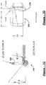
Figure 1 , an embodiment of asurgical clamp 100 engages with an example of a surgicalclamp installation tool 102. In these embodiments, theclamp 100 and theinstallation tool 102 are designed for performing bariatric surgery through a surgical trochar. Theclamp 100, in a preferred embodiment, may be approximately fifteen to thirty centimeters in length to accommodate partitioning of a human stomach. To accommodate insertion through a trochar, theclosed clamp 100 will preferably have a diameter or circumference less than fifteen millimeters over the entirety of its length or along the majority of its length. A non-handle section of theinstallation tool 102 intended for insertion through the trochar has a similar diameter or a smaller diameter. It is envisioned that other embodiments of the clamp and examples of the installation tool can be of other sizes. It is additionally envisioned that the clamp may be articulated in at least one plane to provide different angles and lengths of partition to the stomach. It is also envisioned that other embodiments of the clamp examples of the installation tool can be for clamping other parts of the human body and/or for clamping other types of bodies or structures. - Referring to
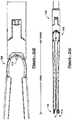
Figure 2 , thesurgical clamp 100 has two elongatedmembers bight portion 106 joins the two elongated members at a proximal end of theclamp 100 and biases the two elongated members in an open position at a distal end of theclamp 100. As used herein, a bight is a loop, bend, hinge, corner angle, hollow, fold, or similar structure. The bight portion has a slottedaperture 108 such as that shown inFigure 2(b) . A clasp mechanism, has amale component 110 disposed on one of the two elongated members at the distal end, and afemale component 112 disposed on the other of the two elongated members at the distal end. - Particularly to partially partition a stomach in performing bariatric surgery, spacing between the two
elongated members Figure 2(e) . At least one of the sections is apartition forming section 105A located nearer the distal end of theclamp 100 than the proximal end of theclamp 100. At least another of the sections is apassage forming section 105B located nearer the proximal end of theclamp 100, such as near thebight portion 106, than the distal end of theclamp 100. - In order to reduce injury to the partitioned organ, a
padding material 116 is connected to one or more of the two elongated members. For example,padding material 116 can connect to theelongated member 104B at least at a location corresponding to at least part of the partition forming section. In some embodiments, the padding material can be composed predominantly of silicone or fully of silicone. It is also envisioned that the opposing limbs of the clamp may be fitted with magnets to facilitate closure. The engagement feature at the proximal end of theclamp 100 is a slottedaperture 108 as shown inFigure 2(b) having a width and a length larger in size than the width. The length of the slotted aperture is oriented perpendicular with reference to a longitudinal axis of theclamp 100. It is envisioned that other types of engagement features can be employed, such as a socket, a loop, a hook, a clasp, a string, magnetic, etc. - In some embodiments, the
male component 110 of the clasp at the distal end of the clamp can be an end of theelongated member 104A that flares away from a longitudinal axis of the clamp when the clamp is forced to a closed position. Accordingly, thefemale component 112 can be a loop attached to the end of theelongated member 104B and disposed to engage themale component 110 of theelongated member 104A when the clamp is forced to the closed position. This can be seen more clearly in connection withFigure 2(e) . It is envisioned that other types of clasp components can be employed, such as those found in a hinge, such as a living hinge, hook and loop, spring ring, lobster or trigger, toggle, tube, bolt and bolt hole, screw and threaded aperture, or any other type of closure arrangement. - Returning to
Figure 1 and referring generally to bothFigure 1 andFigure 2 , theclamp 100, in use, engages with the installation tool by the slottedaperture 108. For example, theinstallation tool 102 has an elongated member, such as a pull-rod 138, having a proximal end and a distal end that has an engagement feature. The distal end of the elongated member of theinstallation tool 102 engages with the proximal end of theclamp 100 through the slottedaperture 108 of thebight portion 106. In some examples the engagement feature takes the form of a T-bar 118. This T-bar 118 is sized and shaped to allow insertion thereof through the slottedaperture 108 to engage theclamp 100. - The
installation tool 102 may include a lever radially engaged with the pull-rod at its proximal end at ahandle 122 that may be configured as athumbwheel 120 that extends out of thehandle 122 of theinstallation tool 102 through an aperture. While the T-bar 118 is inserted through the slottedaperture 108, actuating thethumbwheel 120 can cause the T-bar 118 to rotate ninety degrees as illustrated in one embodiment from a first position shown inFigure 2(c) and in a second position as shown inFigure 2(d) . - At this point, retracting the pull rod, which may be achieved by squeezing a
trigger 128 to retract the pull rod, forces the proximal end of theclamp 100 up against and progressively further between guide members of the surgicalclamp installation tool 102, such as a pair ofwedges installation tool 102. A curvature or incline imparted to the articulating head of theinstallation tool 102 by the pair of wedges can be keyed to a curvature or incline of thebight portion 106 of theclamp 100 in such a way that fully or more fully retracting the pull-rod forces the normallyopen clamp 100 to a closed position such as that shown inFigure 2(e) . - Turning to
Figures 2(f) - 2(k) , the various clamp features can be readily appreciated. These features includebight portion 106, slottedaperture 108,male component 110,female component 112, andpadding material 116. It should be readily understood that thepadding material 116 can be configured as a pair sleeves as shown, but that other configurations may also be employed. Moreover, non-linear shapes may be utilized for various types of applications in clamping various types of organs, as desired. - Turning now to
Figure 3 and referring generally toFigure 1 andFigure 3 , retraction of the pull-rod of theinstallation tool 102 is accomplished by actuation or movement of another lever or trigger that is engaged to the proximal end of the pull-rod, such as through an axial engagement. This lever can be configured as thetrigger 128 that extends out of thehandle 122 through an aperture or slotted opening. The shape of the handle and disposition of the trigger are, preferably, ergonomically configured to allow the surgeon to hold the installation tool parallel to the ground near waist level to grip thehandle 122 and thetrigger 128 in one hand. Thethumbwheel 120 is disposed to be within easy reach of the thumb of that hand to facilitate holding of theclamp 100 by the surgeon in the other hand while engaging the clamp to the articulatinghead 126. Thethumbwheel 120 may be conveniently adjusted to rotate the T-bar 118 to a desired position to lock the T-bar 118 to theclamp 100 at thebight portion 106 through the slottedaperture 108. In one embodiment, thethumbwheel 120 may rotate the T-bar 118 by ninety degrees. - Once the surgeon has rotated and retracted the pull-rod using T-
bar 118 and trigger 128 with one hand, the surgeon's other hand becomes free for other tasks, such as actuating yet another lever protruding from thehandle 122 and configured, for example, as adial 130. With theclamp 100 pulled closed or partially closed against the pair of wedges, thehead 126 can be articulated from side to side by rotating thisdial 130. The motion of the articulatinghead 126 through rotation of thedial 130 is illustrated in one embodiment in the top view of theinstallation tool 102 inFigure 3(b) atarrow 300 showing a range of motion or articulation in one embodiment. - Turning now to
Figure 4 , in some embodiments, turning thedial 130 can turn ahub 132 or connector inside or adjacent thehandle 122 that is connected to a pair ofguidelines guidelines rod 138, may extend through an elongated, rigid sleeve, such as acylindrical tube 136, for connection on either side of a swivel mount of the articulatinghead 126. It is envisioned that the guidelines can be flexible or rigid, that thecylindrical tube 136 can be rigid or semi-rigid, and that the pull-rod 138 can be rigid or semi-rigid. By semi-rigid, it is meant that the pull-rod 138 can be flexible or partially flexible at least in the plane of articulation along at least part of its length near the distal end of theinstallation tool 102, but still axially and rotationally rigid or semi-rigid along its length. Thus, when theinstallation tool 102 and clamp 100 are held parallel to the ground, the pull-rod 138 can be rotated and retracted by actuation of thethumbwheel 120 and trigger 128, and thehead 126 can be articulated in a plane orthogonal to the gravity vector by manipulation of thedial 130. The plane of articulation may be adjustable in certain embodiments, or may be set in a desired plane that is not orthogonal to the gravity vector. - Turning now to
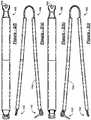
Figure 5 , other embodiments of theclamp 200 andinstallation tool 202 can include aclamp 200 made of multiple pieces, a longermain tube 204, and athumb lever 206 on thedial 130 to articulate the head of thetool 102 that is attached to theclamp 200. In some embodiments, theclamp 200 can be a three-piece clamp. Aratchet release 208 can also be provided on theinstallation tool 202 that, when pressed, allows the pull rod to extend, which in turn will release theclamp 200 allowing it to reopen. In other words, as the surgeon presses on thetrigger 210, causing the pull-rod to retract and theclamp 200 to close, a ratchet mechanism catches thetrigger 210 in the pressed in position. Thus, the pull-rod will remain retracted and clamp 200 will not reopen even if the surgeon releases pressure on thetrigger 210. - Turning now to
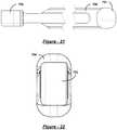
Figure 6 , and referring generally toFigures 6A-6D , one piece of a three-piece clamp can be arigid member 212 having amale clasp end 214. As will be described further below with reference toFigure 9 , thisrigid member 212 serves as one of the elongated members of theclamp 200 for forming the partition that divides the stomach. It can be made of plastic, metal, or any other rigid material. An example material is hardened titanium.Figure 6(c) demonstrates an exemplary contour ofmale clasp end 214, whileFigure 6(d) demonstrates an exemplary contourrigid member 212. It should be readily understood that the exemplary contour ofrigid member 212 renders it concave on an inner surface to be disposed toward an outer surface of an organ to be clamped, and convex on an outer surface for engagement with a spring component. However, other shapes may be used as desired. - Turning next to
Figure 7 , and referring generally toFigures 7A-7D , another piece of the three-piece clamp can be arigid member 216 having afemale clasp end 218 that includes a hingedloop 220. As will be described further below with reference toFigure 9 , thisrigid member 216 serves as one of the elongated members of the clamp for forming the partition that divides the stomach. It can be made of plastic, metal, or any other rigid material. An example material is hardened titanium. Similarly, theloop 220 can be made of various materials, an example of which is titanium wire. - Turning next to
Figure 8 , and referring generally toFigures 8A-8D , a third piece of the three-piece clamp can be aspring member 222 having a slottedbight portion 224. As will be further described below with reference toFigure 9 , the spring member engages with the rigid members to form the clamp and provides the bight portion that permits formation of a passage between the two partitioned regions of the clamped stomach. It can be made of plastic, metal, or any other springy material. An example material is spring tempered titanium. - Turning now to
Figure 9 , and referring generally toFigures 9A-9D , the three-piece clamp can be assembled by engaging therigid members spring member 222. For example, the rigid members can be welded or coupled to arms of spring member atvarious locations 226. In one embodiment, therigid members spring member 222, with theloop 220 arranged to hinge towards and engage themale clasp end 214 of the distal end ofrigid member 212. Thus, therigid members spring member 222 forms a passage between the partitioned regions of an organ or body as shown inFigure 10 . Theserigid members rigid members - Turning now to
Figure 10 , some examples of the surgical clamp installation tool can be used to install theclamp 100 within an abdominal cavity in order to perform bariatric surgery. In particular, the clamp can be positioned, closed, and latched to partition the stomach into a smallvertical pouch 500 and an excludedsection 502. Thevertical pouch 500 receives food at 504, but the food is not able to enter the excludedsection 502. Using the installation tool 102 (or 202) to engage with thebight portion 106 of theclamp 100, theclamp 100 may be installed in a substantially vertical position on the stomach in one embodiment. That is, if the human patient having theclamp 100 installed were to stand upright, the longitudinal axis of theclamp 100 would be substantially parallel to the gravity vector. Thus, a passage forming section formed in the bottom of the stomach by the clamp allows gastric juices to flow at 506 from the excludedsection 502 into thevertical pouch 500. - Turning to
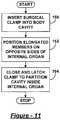
Figure 11 , a method for clamping an internal organ can include inserting a surgical clamp through an opening into a body of a living organism atblock 150. Then the two elongated members of the surgical clamp are positioned on opposite sides of an internal organ of the living organism atblock 152. Atblock 154, closing and latching the surgical clamp to partition a cavity inside the internal organ includes clamping the exterior of the internal organ with the two elongated members. - As mentioned above, the internal organ can be a human stomach. In this case, closing and latching the clamp can include installing the clamp in a substantially vertical or angled position with a passage forming section of the clamp located towards a bottom of the stomach. This positioning can create a small, vertical stomach pouch and thereby limit the intake of food into an excluded section or portion of the stomach, but still allow gastric juices from the excluded portion of the stomach to flow into the vertical stomach pouch. This partitioning can alter the production of hormones, enzymes and chemicals that affect metabolism, energy levels, hunger, digestion, and absorption of nutrients that are affected by exclusion of gastric fundus and body of the stomach by the partitioning. Sheathing the elongated members of the clamp in silicone padding material along a majority of their length is intended to reduce trauma and/or necrosis of the stomach or other internal organ and enable successful reversal of the surgery. Thus, the method can further include reversing the surgery by removing the clamp.
- Inserting the surgical clamp can include performing natural orifice transluminal endoscopic surgery (NOTES). Alternatively, or additionally, it can include performing a combination of NOTES and an assistant trochar placed into an abdominal cavity. This combination can include two or more of a conventional, laparoscopic, NOTES, and one port technique. The NOTES technique can include at least one of transgastric, transvaginal, transrectal, transcolonic, or combinations thereof. The one port technique is used for the introduction of several instruments, and encompasses a one port abdominal (including umbilical), perineal, retroperitoneal approaches, or combinations thereof.
- Turning to
Figure 12 , a method for clamping an internal organ can include engaging a surgical clamp to a head of a surgical clamp installation tool atblock 160. Atblock 162, the surgical clamp installation tool can be employed to close the clamp and insert the clamp through an opening in a body cavity of a living organism. Then the tool can be employed atblock 164 to reopen the clamp and to position elongated members of the clamp on opposite sides of an internal organ within the body cavity. Next, atblock 166, the tool can be employed to close the clamp upon the internal organ and thereby partition a cavity inside the internal organ. The limbs, arms, or elongated members of the clamp close in such a fashion as causing a gradual diminishing space between the two limbs, as the space opening extends proximally, accounting for the different thickness of the stomach. The clamp closes in a fashion that exerts enough pressure to maintain the opposite walls closed to each other without creating damage/trauma/ischemia to the stomach or other organ walls themselves. Then atblock 168, the clamp can be latched to fix it in position to partition the internal organ and the cavity inside the internal organ. Also, atblock 170, the clamp can be disengaged from the head of the surgical clamp installation tool, and the tool can be retracted from the body cavity atblock 172. It is envisioned that the clamp may be configured to latch automatically when the clamp is fully closed. Alternatively, the tool may first be disengaged and removed, and the clamp subsequently latched using an additional tool. Moreover, additional steps may be employed to secure the clamp in place, such as using sutures. - As already described above, padding material can be employed on surfaces of the elongated members of the surgical clamp to reduce damage to the internal organ that would prevent reversal of the surgical procedure. In other embodiments, the thickness or surface contour of the elongated members or arms of the surgical clamp may be provided to align with the particular organ or body being clamped so as to provide the desired pressure or force at each location of the organ or body being clamped. Additionally, engaging the surgical clamp to the head of the surgical clamp installation tool may include passing a T-bar adjacent the end of a pull rod of the installation tool through a slotted aperture formed in a bight portion of the clamp, and rotating the T-bar using a lever or dial. Also, employing the surgical clamp installation tool to close and reopen the clamp may include operating a lever or trigger on a handle of the installation tool to pull and release the pull rod. Further, employing the surgical clamp installation tool to position the elongated members of the surgical clamp may include manipulating a dial on a handle of the installation tool to articulate the head from side to side in a desired plane(s).
- Turning now to
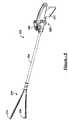
Figure 13 , another embodiment of asurgical clamp 600 andsurgical installation tool 602 is similar in structure and function to those embodiments described above. One notable difference from the embodiments previously described is that the articulatinghead 604 of thesurgical installation tool 602 is keyed with a curvature or radius configured to hold theclamp 600 securely in place while permitting theclamp 600 to remain in an open position. This configuration permits a surgeon holding theinstallation tool 602 in one hand to hold theclamp 600 securely in the articulatinghead 604 of thetool 602 while pressing the distal ends of theclamp 600 together with the other end for entry to a trochar. Once the distal ends of theclamp 600 have entered the trochar, the trochar then holds the ends shut, and permitting the surgeon free use of the other hand. Upon entry to the abdominal cavity, the clamp naturally springs open for engagement with a bodily organ, such as the stomach, and the surgeon can articulate the head from side to side while it is held securely in thehead 604 while still in the open position. Once in position, the surgeon can close the clamp using sutures and/or by applying pressure externally or internally using other surgical tools. Thus, theinstallation tool 602 may not be employed to close the clamp on an internal organ of the patient, but may be employed to hold, insert, and articulate the clamp into position. - Referring now to
Figure 14 ,clamp 600 can have a three piece design similar to that described above. In other words, it can have aspring member 606 that is comprised predominantly of spring steel, and that is engaged with lower and upperrigid members rigid members rigid member 610, as well as in an upper portion ofspring member 606. A surgeon can employ these suture holes 612 to secure theclamp 600 in place on a stomach or other bodily organ. It is envisioned that additional or alternative suture holes 612 can be provided, such as in lowerrigid member 608 and lower portion ofspring member 606, and that positions of the suture holes 612 can be different from those shown. However, as will be more fully described below with reference toFigures 19-27 , the placement of suture holes in the upperrigid member 608 and upper portion ofspring member 606 can permit suturing of theclamp 600 in place prior to application of a silicone sleeve (seeFigures 19-27 ) that slides onto the clamp via the un-sutured lowerrigid member 608 and lower portion ofspring member 606. Yet, once the sleeve is installed, it should be understood that additional suture holes 612 provided in lowerrigid member 608 and/or lower portion ofspring member 606 may prove useful in a subsequent application of additional sutures. - Turning now to
Figures 15(a)-15(f) and referring generally thereto, it should be appreciated that a double row ofsuture holes 612A-612H can be provided inspring member 606 and upperrigid member 610, a distal portion of which can exhibit amale clasp feature 614 positioned to engage a female clasp feature, such as awire loop 616, of lowerrigid member 608.Suture holes spring member 606 at a location that lies between a position at which upperrigid member 610 is engaged tospring member 606, and a position at which aslot 618 is formed in a bight portion ofspring member 606. In the case that the distal end of upperrigid member 610 exhibits amale clasp feature 614, such as a planular curvature away from a plane in which the upperrigid member 610 predominantly lies, a complimentary female clasp feature can be exhibited by a distal end of lowerrigid member 608, such as the aforementionedrectangular wire loop 616 engaged by ahinge formation 620 provided in the distal end of lowerrigid member 608. It should be readily understood that the same functionality can be achieved if upperrigid member 610 exhibits the female clasp feature, and lowerrigid member 608 exhibitsmale clasp feature 614. Thus, the positions of the clasp features can be reversed in other embodiments. - Turning now to
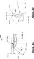
Figure 16 , another additional feature ofclamp 600 can be a detent that is 622 formed inhinge formation 620, and that engageswire loop 616 of the female clasp feature. Thisdetent 622 can be positioned on thehinge formation 620 at a location that is most distal when theclamp 600 is held in a closed position, and it can be sized and shaped to hold thewire loop 616 in a lowered position at which theloop 616 lies in a plane parallel to a plane in which lowerrigid member 608 predominantly lies. A similar or identical detent (not shown) can be provided on an opposite side ofhinge formation 620, and it can be similarly distally positioned to assist in holding thewire loop 616 in the aforementioned lowered position. This lowered position allows theclamp 600 to be inserted through a trochar and guided to enclose a bodily organ, such as a stomach, at which point the aforementioned silicone sleeve (seeFigures 19-27 ) can be partially applied. Then, before the silicone sleeve is fully engaged to theclamp 600,wire loop 616 can be forced out ofdetent 622 into a raised position at which it engages themale clasp feature 614 of theclamp 600. - Before raising the
wire loop 616, it is envisioned that theclamp 600 can be pressed into a closed position by use of two or more graspers inserted into the abdominal cavity through additional trochars (i.e., multiport technique). Then, a suture tag pre-applied towire loop 616 can be used to forcewire loop 616 out ofdetent 622 into the raised position, resulting in thewire loop 616 engaging themale clasp feature 614 and holding theclamp 600 in the closed position without assistance from the two or more graspers. Alternatively or additionally, it is envisioned that closing and latching of theclamp 600 can be achieved by utilizing any suitable endoscopic surgical tools and techniques as will be readily apparent to one skilled in the art from the present disclosure. - Turning now to
Figures 17(a)-17(f) and referring generally thereto, an endoscopic surgical installation tool for engaging and manipulating the clamp can be similar to those described above. For example, the installation tool can have ahandle 650,trigger 652, pull rod, T-bar 654,cylindrical tube 656, dial 658 (e.g., with thumb lever), hub, guidelines, and articulatinghead 604 that are identical or similar to those described above. However, as previously described, a curvature or incline imparted to thehead 604 by wedges of thehead 604 can be keyed to a bight portion of the previously described clamp so as to hold the clamp in a fully open or predominantly open position when T-bar 654 has been fully retracted by actuation oftrigger 652. Additionally, alatch release 660 can be provided that can extend from both sides ofhandle 650 for ergonomic, ambidextrous operation. - Turning now to
Figure 17 , thelatch release 660 can have a hinged plate with a retention spring that forces thelatch release 660 upwards to engage alatch 662 provided at a proximal end of pull rod 664. In use, a surgeon can engage the T-bar to theclamp 600 by rotating theclamp 600 and/or installation tool in a common longitudinal axis until the T-bar fits through the notch in the bight portion of theclamp 600, and then rotating theclamp 600 and/or installation tool an integer multiple of ninety degrees until a length direction of the T-Bar is perpendicular to a length direction of the notch. Then, actuation oftrigger 652 can retract pull rod until opposing latch surfaces (e.g., edges, extensions, faces, flanges, gouges, hooks, inclines, ledges, lips, notches, overhangs, projections, protrusions, ribs, ridges, skirts, serrations, slits, slots, teeth, wedges, and combinations thereof) of thelatch 662 and release 660 can catch and hold the pull rod 664 in a fully retracted or predominantly retracted position. - Once the
latch 662 is engaged, theclamp 600 is ready to be inserted into an inflated abdominal cavity through a trochar as described above, and a seal provided betweencylindrical tube 656 andclevis 668 can prevent out gassing from the abdominal cavity through thehead 604 and/orcylindrical tube 656. Alternatively, the seal can be provided anywhere insidecylindrical tube 656. In some embodiments, the seal is achieved by using a circular silicone die having a slit and a hole in the middle, with the pull rod 664 threaded through the hole. - Once the
clamp 600 is in position within the abdominal cavity to enclose and partition the stomach or other organ, pressing down onlatch release 660 can permit automatic extension of pull rod 664 by action of a torsion spring provided to trigger screw 666 to force de-actuation oftrigger 652. The T-bar can then be disengaged from the clamp by rotating the installation tool along its longitudinal axis an integer multiple of ninety degrees and removing it from the trochar. Thus, it should be apparent that, in some embodiments, the pull rod may not be configured to rotate as in alternative embodiments described above, but only to retract and to extend. - Turning now to
Figure 19 , asilicone sleeve 700 can be configured to engageclamp 600. In some embodiments,silicone sleeve 700 can be formed to cover primarily an upper arm and both ends ofclamp 600. Thissilicone sleeve 700 can be used as padding to protect surrounding organs from irritation or damage. Thickness of the silicone can be varied for different applications, such as partitioning an organ, stomach, or vessel. - Turning now to
Figures 20-27 and referring generally thereto, thesilicone sleeve 700 can havetubular section 702 at a proximal end that slides onto the lower arm of clamp and can be manipulated into position to encapsulate the previously described bight portion of the clamp. The clamp can then be closed and latched as described above. Presuming that the upper arm of the clamp has already been sutured to the organ, stomach, or vessel, a distal end of thesleeve 700 can then be engaged to encapsulate the distal end of the clamp. For this purpose, the distal end of thesleeve 700 can be configured as alatch cap 704 that is form fitted to the closed latch features (seeFig. 25 ). Apadding strip 706 situated between thetubular section 702 andlatch cap 704 can be sized to a length of the clamp so as to be stretched taught across the upper arm of the clamp once thesleeve 700 is installed. Aslot engaging feature 708 formed inside oftubular section 702 can be provided to engage with the previously described slot in the bight portion of the clamp by plugging the slot, and thus hold the tubular section of thesleeve 700 in place on the bight portion of the clamp. - Turning now to
Figure 28 , a method of performing surgery can begin atstep 750 by engaging the previously described clamp to the previously described surgical installation tool in one or more of the previously described manners. Thereafter, the clamp can be inserted through a trochar atstep 752, and positioned to enclose an organ (e.g., stomach, vessel, etc.) atstep 754. Next, atstep 756, an upper arm of the clamp can be sutured to the organ though suture holes supplied in the clamp as previously described, and the installation tool can be disengaged and removed from the trochar atstep 758. Thereafter, the previously described silicone sleeve can be slid over a lower arm of the clamp atstep 760 as previously described, and the clamp can be closed and latched atstep 762. Finally, atstep 764, a latch cap of the silicone sleeve can be fit over the latch of the clamp, and additional sutures can be applied if desired. It should be understood that the sequence of the aforementioned steps can vary in additional or alternative embodiments, and that additional or alternative steps can be employed as will be readily apparent to one skilled in the art. - A number of additional and alternative embodiments of the surgical clamp can have characteristics that are different from those described above. For example, it is envisioned that a surgical clamp not intended for bariatric surgery might not have a passage forming section, and that such a clamp might be smaller or larger, depending on the purpose of the clamp. For example, the clamp can be one-tenth of an inch (2,54 mm) in length to partition a blood vessel, or twenty-two centimeters in length to partition a stomach. Moreover, the clamp can be configured to partition any internal organ, and can vary in length accordingly between these two example lengths, or be longer or shorter as required. Also, the guide members might have one or more protrusions aligned with the engagement feature and configured for insertion into the slot formed in the bight portion of the clamp. Moreover, it is envisioned that the installation tool can be integrated with an endoscope and/or surgical robot, and that appropriate robotic elements can be included in place of or in addition to those described above.
Claims (13)
- A surgical clamp (100) comprising:at least two elongated members (104A, 104B) each having an elongated length, wherein at least one surface of the at least two elongated members has a padding material (116) positioned adjacent at least a portion of the surface;a bight portion (106) joining said two elongated members at a proximal end of the surgical clamp and biasing said two elongated members in an open position at a distal end of the surgical clamp, wherein said bight portion has at least one engagement feature formed therein, wherein the engagement feature comprises a slotted aperture (108) formed through a proximal surface of the bight portion and having a length oriented perpendicular to a longitudinal axis of the surgical clamp; wherein the length of the slotted aperture is greater than the width of the slotted aperture; anda clasp mechanism having a male component (110) disposed on one of the two elongated members at the distal end of the surgical clamp and a female component (112) disposed on the other of the two elongated members at the distal end of the surgical clamp.
- The surgical clamp of claim 1, wherein the at least two elongated members are attached to elongated members of a spring component that serves as the bight portion.
- The surgical clamp of claim 2, wherein the elongated members are comprised of titanium, and a surface of the at least two elongated members of the surgical clamp is curved and contacts at least one of the elongated members of the spring component.
- The surgical clamp of claim 1, wherein spacing between the interior surfaces of said at least two elongated members includes a partition forming section (105A) located nearer the distal end of the surgical clamp than the proximal end of the surgical clamp, and a passage forming section (105B) located nearer the proximal end of the surgical clamp than the distal end of the surgical clamp.
- The surgical clamp of claim 4, wherein the bight portion includes a spring portion that serves at least partially as the passage forming section.
- The surgical clamp of claim 5, wherein said padding material is connected to at least one of the two elongated members at least at a location on the surface corresponding to at least part of the partition forming section.
- The surgical clamp of claim 1, wherein the male component of the clasp mechanism corresponds to an end (614) of the elongated member that flares away from a longitudinal axis of the surgical clamp when the surgical clamp is placed in a closed position, and the female component of the clasp mechanism corresponds to a loop (616) disposed to engage the end of the elongated member when the surgical clamp is placed in the closed position, and a hinge formation (620) engaging the loop has a detent (622) distally positioned to retain the loop in a plane parallel to a plane in which a longitudinal axis of the clamp predominately lies when the clamp is closed.
- The surgical clamp (100) of claim 1 being adapted for use in clamping an internal organ.
- The surgical clamp as set forth in claim 8, wherein the internal organ is a human stomach.
- The surgical clamp as set forth in claim 9, wherein the clamping of the internal organ is part of:a laparoscopic surgery;a open conventional surgery;a single site surgery;a natural orifice transluminal endoscopic surgery (NOTES); ora combination of NOTES and an assistant trochar placed into an abdominal cavity.
- The surgical clamp as set forth in claim 10, wherein the combination of NOTES and an assistant trochar includes two or more of a conventional, laparoscopic, NOTES, and one port technique.
- The surgical clamp as set forth in claim 10, wherein the NOTES technique includes at least one of transgastric, transvaginal, transrectal, transcolonic, or combinations thereof.
- The surgical clamp as set forth in claim 8, wherein the two elongated members are composed of hardened titanium and attached by welding to interior surfaces of a spring member (222) made of steel, wherein said spring member comprises said bight portion.
Priority Applications (1)
| Application Number | Priority Date | Filing Date | Title |
|---|---|---|---|
| EP18166701.5AEP3398538A3 (en) | 2010-01-29 | 2011-01-31 | Surgical clamp |
Applications Claiming Priority (2)
| Application Number | Priority Date | Filing Date | Title |
|---|---|---|---|
| US29972510P | 2010-01-29 | 2010-01-29 | |
| PCT/US2011/023205WO2011094700A1 (en) | 2010-01-29 | 2011-01-31 | Surgical clamp and surgical clamp installation tool |
Related Child Applications (1)
| Application Number | Title | Priority Date | Filing Date |
|---|---|---|---|
| EP18166701.5ADivisionEP3398538A3 (en) | 2010-01-29 | 2011-01-31 | Surgical clamp |
Publications (3)
| Publication Number | Publication Date |
|---|---|
| EP2528512A1 EP2528512A1 (en) | 2012-12-05 |
| EP2528512A4 EP2528512A4 (en) | 2014-10-22 |
| EP2528512B1true EP2528512B1 (en) | 2018-04-11 |
Family
ID=44319854
Family Applications (2)
| Application Number | Title | Priority Date | Filing Date |
|---|---|---|---|
| EP11737828.1AActiveEP2528512B1 (en) | 2010-01-29 | 2011-01-31 | Surgical clamp |
| EP18166701.5AWithdrawnEP3398538A3 (en) | 2010-01-29 | 2011-01-31 | Surgical clamp |
Family Applications After (1)
| Application Number | Title | Priority Date | Filing Date |
|---|---|---|---|
| EP18166701.5AWithdrawnEP3398538A3 (en) | 2010-01-29 | 2011-01-31 | Surgical clamp |
Country Status (4)
| Country | Link |
|---|---|
| US (4) | US8529585B2 (en) |
| EP (2) | EP2528512B1 (en) |
| ES (1) | ES2671595T3 (en) |
| WO (1) | WO2011094700A1 (en) |
Cited By (6)
| Publication number | Priority date | Publication date | Assignee | Title |
|---|---|---|---|---|
| US10369036B2 (en) | 2007-01-19 | 2019-08-06 | Advanced Bariatric Technology, Llc | Vertically oriented band for stomach |
| US10420664B2 (en) | 2014-08-26 | 2019-09-24 | Advanced Bariatric Technology, Llc | Bariatric clamp with suture portions, magnetic inserts and curvature |
| US10456141B2 (en) | 2012-08-09 | 2019-10-29 | Advanced Bariatric Technology, Llc | Polymer overmolded bariatric clamp and method of installing |
| US10932938B2 (en) | 2017-07-24 | 2021-03-02 | Advanced Bariatric Technology, Llc | Clamp installation tool |
| US11337839B2 (en) | 2016-07-07 | 2022-05-24 | Advanced Bariatric Technology, Llc | Inflatable bariatric clamp |
| US11583290B2 (en) | 2010-01-29 | 2023-02-21 | Advanced Bariatric Technology, Llc | Surgical clamp |
Families Citing this family (120)
| Publication number | Priority date | Publication date | Assignee | Title |
|---|---|---|---|---|
| EP2641548B1 (en) | 2004-10-08 | 2015-08-19 | Covidien LP | Endoscopic surgical clip applier |
| CA2809110A1 (en) | 2004-10-08 | 2006-04-20 | Tyco Healthcare Group Lp | Apparatus for applying surgical clips |
| US9763668B2 (en) | 2004-10-08 | 2017-09-19 | Covidien Lp | Endoscopic surgical clip applier |
| EP2015681B1 (en) | 2006-05-03 | 2018-03-28 | Datascope Corp. | Tissue closure device |
| CA2605135C (en) | 2006-10-17 | 2014-12-30 | Tyco Healthcare Group Lp | Apparatus for applying surgical clips |
| EP2157920B1 (en) | 2007-03-26 | 2017-09-27 | Covidien LP | Endoscopic surgical clip applier |
| CN102327136B (en) | 2007-04-11 | 2014-04-23 | 柯惠Lp公司 | Surgical clip applier |
| WO2010011661A1 (en)* | 2008-07-21 | 2010-01-28 | Atricure, Inc. | Apparatus and methods for occluding an anatomical structure |
| US8465502B2 (en) | 2008-08-25 | 2013-06-18 | Covidien Lp | Surgical clip applier and method of assembly |
| US20110208212A1 (en) | 2010-02-19 | 2011-08-25 | Zergiebel Earl M | Surgical clip applier |
| US9358015B2 (en) | 2008-08-29 | 2016-06-07 | Covidien Lp | Endoscopic surgical clip applier with wedge plate |
| US8267944B2 (en) | 2008-08-29 | 2012-09-18 | Tyco Healthcare Group Lp | Endoscopic surgical clip applier with lock out |
| US8409223B2 (en) | 2008-08-29 | 2013-04-02 | Covidien Lp | Endoscopic surgical clip applier with clip retention |
| US8734469B2 (en) | 2009-10-13 | 2014-05-27 | Covidien Lp | Suture clip applier |
| US9186136B2 (en) | 2009-12-09 | 2015-11-17 | Covidien Lp | Surgical clip applier |
| US8545486B2 (en) | 2009-12-15 | 2013-10-01 | Covidien Lp | Surgical clip applier |
| US8403945B2 (en) | 2010-02-25 | 2013-03-26 | Covidien Lp | Articulating endoscopic surgical clip applier |
| US8968337B2 (en) | 2010-07-28 | 2015-03-03 | Covidien Lp | Articulating clip applier |
| US8403946B2 (en) | 2010-07-28 | 2013-03-26 | Covidien Lp | Articulating clip applier cartridge |
| US9011464B2 (en) | 2010-11-02 | 2015-04-21 | Covidien Lp | Self-centering clip and jaw |
| US9186153B2 (en) | 2011-01-31 | 2015-11-17 | Covidien Lp | Locking cam driver and jaw assembly for clip applier |
| US9775623B2 (en) | 2011-04-29 | 2017-10-03 | Covidien Lp | Surgical clip applier including clip relief feature |
| RU2559922C1 (en)* | 2011-08-15 | 2015-08-20 | Этрикьюэ Инк. | Surgical device |
| US20130131697A1 (en) | 2011-11-21 | 2013-05-23 | Covidien Lp | Surgical clip applier |
| US9364239B2 (en) | 2011-12-19 | 2016-06-14 | Covidien Lp | Jaw closure mechanism for a surgical clip applier |
| US9364216B2 (en) | 2011-12-29 | 2016-06-14 | Covidien Lp | Surgical clip applier with integrated clip counter |
| US9408610B2 (en) | 2012-05-04 | 2016-08-09 | Covidien Lp | Surgical clip applier with dissector |
| US9532787B2 (en) | 2012-05-31 | 2017-01-03 | Covidien Lp | Endoscopic clip applier |
| US9209529B2 (en)* | 2012-12-04 | 2015-12-08 | Thomas & Betts International, Llc | Module edge grounding cable clips |
| US9968362B2 (en) | 2013-01-08 | 2018-05-15 | Covidien Lp | Surgical clip applier |
| US9113892B2 (en) | 2013-01-08 | 2015-08-25 | Covidien Lp | Surgical clip applier |
| US9750500B2 (en) | 2013-01-18 | 2017-09-05 | Covidien Lp | Surgical clip applier |
| FR3005564B1 (en)* | 2013-05-20 | 2018-01-12 | Cousin Biotech | INSTRUMENT FOR USE IN MODIFYING THE VOLUME OF THE STOMACH OF A PATIENT. |
| US9775624B2 (en) | 2013-08-27 | 2017-10-03 | Covidien Lp | Surgical clip applier |
| WO2015077356A1 (en) | 2013-11-19 | 2015-05-28 | Wheeler William K | Fastener applicator with interlock |
| MX369672B (en) | 2013-12-17 | 2019-11-15 | Standard Bariatrics Inc | Resection line guide for a medical procedure and method of using same. |
| US10219817B2 (en) | 2014-03-13 | 2019-03-05 | Lsi Solutions, Inc. | Surgical clamp and clamp jaw |
| WO2015153324A1 (en) | 2014-03-29 | 2015-10-08 | Standard Bariatrics, Inc. | End effectors, surgical stapling devices, and methods of using same |
| AU2015241193B2 (en) | 2014-03-29 | 2020-01-02 | Standard Bariatrics, Inc. | End effectors surgical stapling devices, and methods of using same |
| WO2016037158A1 (en) | 2014-09-05 | 2016-03-10 | Standard Bariatrics, Inc. | Sleeve gastrectomy calibration tube and method of using same |
| US10702278B2 (en) | 2014-12-02 | 2020-07-07 | Covidien Lp | Laparoscopic surgical ligation clip applier |
| US9931124B2 (en) | 2015-01-07 | 2018-04-03 | Covidien Lp | Reposable clip applier |
| CN107205747B (en) | 2015-01-15 | 2020-09-08 | 柯惠有限合伙公司 | Reusable endoscopic surgical clip applier |
| US10292712B2 (en) | 2015-01-28 | 2019-05-21 | Covidien Lp | Surgical clip applier with integrated cutter |
| US10159491B2 (en) | 2015-03-10 | 2018-12-25 | Covidien Lp | Endoscopic reposable surgical clip applier |
| WO2017017587A2 (en)* | 2015-07-24 | 2017-02-02 | Cliptip Medical Ltd | Thickness-adjustable hemostatic clips, clip appliers, and applications thereof |
| US10285837B1 (en) | 2015-09-16 | 2019-05-14 | Standard Bariatrics, Inc. | Systems and methods for measuring volume of potential sleeve in a sleeve gastrectomy |
| CN108348259B (en) | 2015-11-03 | 2020-12-11 | 柯惠有限合伙公司 | Endoscopic Surgical Fixture Applicator |
| US10390831B2 (en) | 2015-11-10 | 2019-08-27 | Covidien Lp | Endoscopic reposable surgical clip applier |
| US10905425B2 (en) | 2015-11-10 | 2021-02-02 | Covidien Lp | Endoscopic reposable surgical clip applier |
| US10702280B2 (en) | 2015-11-10 | 2020-07-07 | Covidien Lp | Endoscopic reposable surgical clip applier |
| US20170172780A1 (en)* | 2015-12-22 | 2017-06-22 | Covidien Lp | Methods of performing a bariatric procedure and surgical devices for use therewith |
| CN108472044B (en) | 2016-01-11 | 2021-04-16 | 柯惠有限合伙公司 | endoscope-reserved surgical clip applier |
| AU2016388454A1 (en) | 2016-01-18 | 2018-07-19 | Covidien Lp | Endoscopic surgical clip applier |
| CA2958160A1 (en) | 2016-02-24 | 2017-08-24 | Covidien Lp | Endoscopic reposable surgical clip applier |
| WO2018027788A1 (en) | 2016-08-11 | 2018-02-15 | Covidien Lp | Endoscopic surgical clip applier and clip applying systems |
| CN109640844B (en) | 2016-08-25 | 2021-08-06 | 柯惠Lp公司 | Endoscopic Surgical Clip Appliers and Applicator Systems |
| US10639044B2 (en) | 2016-10-31 | 2020-05-05 | Covidien Lp | Ligation clip module and clip applier |
| US10660651B2 (en) | 2016-10-31 | 2020-05-26 | Covidien Lp | Endoscopic reposable surgical clip applier |
| US10492795B2 (en) | 2016-11-01 | 2019-12-03 | Covidien Lp | Endoscopic surgical clip applier |
| US10426489B2 (en) | 2016-11-01 | 2019-10-01 | Covidien Lp | Endoscopic reposable surgical clip applier |
| US10610236B2 (en) | 2016-11-01 | 2020-04-07 | Covidien Lp | Endoscopic reposable surgical clip applier |
| US10709455B2 (en) | 2017-02-02 | 2020-07-14 | Covidien Lp | Endoscopic surgical clip applier |
| US10758244B2 (en) | 2017-02-06 | 2020-09-01 | Covidien Lp | Endoscopic surgical clip applier |
| US11116514B2 (en) | 2017-02-06 | 2021-09-14 | Covidien Lp | Surgical clip applier with user feedback feature |
| US10660725B2 (en) | 2017-02-14 | 2020-05-26 | Covidien Lp | Endoscopic surgical clip applier including counter assembly |
| US10603038B2 (en) | 2017-02-22 | 2020-03-31 | Covidien Lp | Surgical clip applier including inserts for jaw assembly |
| US11583291B2 (en) | 2017-02-23 | 2023-02-21 | Covidien Lp | Endoscopic surgical clip applier |
| US10548602B2 (en) | 2017-02-23 | 2020-02-04 | Covidien Lp | Endoscopic surgical clip applier |
| US10675043B2 (en) | 2017-05-04 | 2020-06-09 | Covidien Lp | Reposable multi-fire surgical clip applier |
| US10722235B2 (en) | 2017-05-11 | 2020-07-28 | Covidien Lp | Spring-release surgical clip |
| US10639032B2 (en) | 2017-06-30 | 2020-05-05 | Covidien Lp | Endoscopic surgical clip applier including counter assembly |
| US10660723B2 (en) | 2017-06-30 | 2020-05-26 | Covidien Lp | Endoscopic reposable surgical clip applier |
| US10675112B2 (en) | 2017-08-07 | 2020-06-09 | Covidien Lp | Endoscopic surgical clip applier including counter assembly |
| US10932790B2 (en) | 2017-08-08 | 2021-03-02 | Covidien Lp | Geared actuation mechanism and surgical clip applier including the same |
| US10863992B2 (en) | 2017-08-08 | 2020-12-15 | Covidien Lp | Endoscopic surgical clip applier |
| US10786262B2 (en) | 2017-08-09 | 2020-09-29 | Covidien Lp | Endoscopic reposable surgical clip applier |
| US10912562B2 (en) | 2017-08-14 | 2021-02-09 | Standard Bariatrics, Inc. | End effectors, surgical stapling devices, and methods of using same |
| US10786263B2 (en) | 2017-08-15 | 2020-09-29 | Covidien Lp | Endoscopic reposable surgical clip applier |
| US10835341B2 (en) | 2017-09-12 | 2020-11-17 | Covidien Lp | Endoscopic surgical clip applier and handle assemblies for use therewith |
| US10653429B2 (en) | 2017-09-13 | 2020-05-19 | Covidien Lp | Endoscopic surgical clip applier |
| US10835260B2 (en) | 2017-09-13 | 2020-11-17 | Covidien Lp | Endoscopic surgical clip applier and handle assemblies for use therewith |
| US10758245B2 (en) | 2017-09-13 | 2020-09-01 | Covidien Lp | Clip counting mechanism for surgical clip applier |
| US10828036B2 (en) | 2017-11-03 | 2020-11-10 | Covidien Lp | Endoscopic surgical clip applier and handle assemblies for use therewith |
| US10945734B2 (en) | 2017-11-03 | 2021-03-16 | Covidien Lp | Rotation knob assemblies and surgical instruments including the same |
| US11376015B2 (en) | 2017-11-03 | 2022-07-05 | Covidien Lp | Endoscopic surgical clip applier and handle assemblies for use therewith |
| US10932791B2 (en) | 2017-11-03 | 2021-03-02 | Covidien Lp | Reposable multi-fire surgical clip applier |
| US11116513B2 (en) | 2017-11-03 | 2021-09-14 | Covidien Lp | Modular surgical clip cartridge |
| US10722236B2 (en) | 2017-12-12 | 2020-07-28 | Covidien Lp | Endoscopic reposable surgical clip applier |
| US10849630B2 (en) | 2017-12-13 | 2020-12-01 | Covidien Lp | Reposable multi-fire surgical clip applier |
| US10743887B2 (en) | 2017-12-13 | 2020-08-18 | Covidien Lp | Reposable multi-fire surgical clip applier |
| US10959737B2 (en) | 2017-12-13 | 2021-03-30 | Covidien Lp | Reposable multi-fire surgical clip applier |
| US11051827B2 (en) | 2018-01-16 | 2021-07-06 | Covidien Lp | Endoscopic surgical instrument and handle assemblies for use therewith |
| JP7348199B2 (en) | 2018-03-28 | 2023-09-20 | データスコープ コーポレイション | Device for atrial appendage exclusion |
| US10993721B2 (en) | 2018-04-25 | 2021-05-04 | Covidien Lp | Surgical clip applier |
| US10786273B2 (en) | 2018-07-13 | 2020-09-29 | Covidien Lp | Rotation knob assemblies for handle assemblies |
| US11219463B2 (en) | 2018-08-13 | 2022-01-11 | Covidien Lp | Bilateral spring for surgical instruments and surgical instruments including the same |
| US11051828B2 (en) | 2018-08-13 | 2021-07-06 | Covidien Lp | Rotation knob assemblies and surgical instruments including same |
| US11246601B2 (en) | 2018-08-13 | 2022-02-15 | Covidien Lp | Elongated assemblies for surgical clip appliers and surgical clip appliers incorporating the same |
| US11278267B2 (en) | 2018-08-13 | 2022-03-22 | Covidien Lp | Latch assemblies and surgical instruments including the same |
| US11344316B2 (en) | 2018-08-13 | 2022-05-31 | Covidien Lp | Elongated assemblies for surgical clip appliers and surgical clip appliers incorporating the same |
| US11147566B2 (en) | 2018-10-01 | 2021-10-19 | Covidien Lp | Endoscopic surgical clip applier |
| US11229441B2 (en) | 2018-10-04 | 2022-01-25 | Lsi Solutions, Inc. | Minimally invasive surgical clamping device and methods thereof |
| US11524398B2 (en) | 2019-03-19 | 2022-12-13 | Covidien Lp | Gear drive mechanisms for surgical instruments |
| EP3763298B1 (en)* | 2019-07-10 | 2023-11-29 | Micro-Tech (Nanjing) Co., Ltd. | Medical device for causing the hemostasis of a blood vessel |
| US11717301B2 (en) | 2019-09-25 | 2023-08-08 | Lsi Solutions, Inc. | Minimally invasive occlusion device and methods thereof |
| BR112022008009A2 (en) | 2019-11-04 | 2022-07-12 | Standard Bariatrics Inc | SYSTEMS AND METHODS OF PERFORMING SURGERY USING LAPLACE'S LAW TENSION RETRACTION DURING SURGERY |
| US12274635B2 (en) | 2019-11-04 | 2025-04-15 | Standard Bariatrics, Inc. | Systems and methods of performing surgery using laplace's law tension retraction during surgery |
| US20210137524A1 (en)* | 2019-11-13 | 2021-05-13 | Covidien Lp | Multi-Part Ligation Clip |
| CN113116506B (en)* | 2019-12-30 | 2023-09-05 | 北京术锐机器人股份有限公司 | Operation tool head with sealing structure |
| US11779340B2 (en) | 2020-01-02 | 2023-10-10 | Covidien Lp | Ligation clip loading device |
| US11723669B2 (en) | 2020-01-08 | 2023-08-15 | Covidien Lp | Clip applier with clip cartridge interface |
| US12114866B2 (en) | 2020-03-26 | 2024-10-15 | Covidien Lp | Interoperative clip loading device |
| EP4146092A4 (en)* | 2020-05-08 | 2024-08-21 | Cedars-Sinai Medical Center | HEMOCLIP DEPLOYMENT SYSTEMS AND METHODS |
| CN115955943A (en) | 2020-06-30 | 2023-04-11 | 标准肥胖病研究公司 | Systems, devices, and methods for preventing or reducing insufflation loss during laparoscopic procedures |
| US11937828B2 (en)* | 2021-01-26 | 2024-03-26 | Olympus Medical Systems Corp. | Endoscope treatment device |
| US11944321B2 (en) | 2021-01-26 | 2024-04-02 | Olympus Medical Systems Corp. | Endoscopic treatment device |
| AU2022242751B2 (en) | 2021-03-23 | 2024-05-02 | Standard Bariatrics, Inc. | Systems and methods for preventing tissue migration in surgical staplers |
| US12419648B2 (en) | 2022-09-26 | 2025-09-23 | Covidien Lp | Two-part fasteners for surgical clip appliers and surgical clip appliers for deploying the same |
| US20240189130A1 (en)* | 2022-12-12 | 2024-06-13 | King Faisal University | Stapler for performing laparoscopic gastric sleeve procedures |
Family Cites Families (212)
| Publication number | Priority date | Publication date | Assignee | Title |
|---|---|---|---|---|
| US600887A (en) | 1898-03-22 | Clasp or fastening device | ||
| US350850A (en)* | 1886-10-12 | tatum | ||
| US422906A (en)* | 1890-03-11 | Peteh s | ||
| US758449A (en)* | 1903-11-13 | 1904-04-26 | Orrin L Jeralds | Clamp or stop-cock for flexible tubes. |
| US823068A (en)* | 1905-06-16 | 1906-06-12 | James W Mosley | Clamp for flexible tubes. |
| US860344A (en)* | 1907-02-12 | 1907-07-16 | Seamless Rubber Co | Stop-cock for flexible tubes. |
| US1190039A (en)* | 1916-01-22 | 1916-07-04 | Whitall Tatum Co | Clamp for flexible tubes. |
| US1213504A (en)* | 1916-03-06 | 1917-01-23 | Charles P Kuehner | Tube-clamp. |
| US1211718A (en)* | 1916-03-31 | 1917-01-09 | Charles P Kuehner | Tube-clamp. |
| US1275898A (en)* | 1916-07-27 | 1918-08-13 | Brass Goods M F G Co | Wire compression-clamp for tubing and the like. |
| US1297456A (en)* | 1919-01-06 | 1919-03-18 | Brass Goods M F G Co | Tube-compressor. |
| US2519909A (en)* | 1946-10-31 | 1950-08-22 | Macalaster Bicknell Company | Tube valving clamp |
| US3254651A (en) | 1962-09-12 | 1966-06-07 | Babies Hospital | Surgical anastomosis methods and devices |
| US3316914A (en) | 1963-02-14 | 1967-05-02 | Michael B Collito | Surgical methods and devices for anastomosis |
| US3417752A (en) | 1965-11-12 | 1968-12-24 | Byron C. Butler | Magnetic clamp closing device for use with surgical instruments |
| US3766925A (en)* | 1971-05-25 | 1973-10-23 | Eljay Hospital Prod Corp | Surgical clamp with cam-action lever |
| US3822052A (en)* | 1973-04-02 | 1974-07-02 | Illinois Tool Works | Shut off clamp |
| US4060089A (en) | 1975-09-03 | 1977-11-29 | United States Surgical Corporation | Surgical fastening method and device therefor |
| DE2730691C2 (en)* | 1976-07-16 | 1982-12-16 | Maruho Co. Ltd., Osaka | Surgical clip, connecting element for several surgical clips and forceps for opening and closing the same |
| US4428374A (en)* | 1978-12-20 | 1984-01-31 | Auburn Robert M | Umbilical cord clamping assembly |
| US4390019A (en)* | 1979-02-28 | 1983-06-28 | Leveen Harry H | Blood vessel clamp |
| US4414721A (en) | 1980-11-07 | 1983-11-15 | Hufnagel Charles A | Occlusive clip and applicator for constricting flexible tubular members |
| US4346869A (en)* | 1981-03-12 | 1982-08-31 | Macneill Robert L | Tube clamp |
| US4453295A (en)* | 1981-06-17 | 1984-06-12 | Solco Basel Ag | Device for pinching-off hoses |
| US4457756A (en) | 1982-04-14 | 1984-07-03 | Kern Eugene B | Nose bleed clip |
| US4458681A (en)* | 1982-06-10 | 1984-07-10 | Hopkins Donald A | Stomach clamp for and method of proximal gastric partitioning |
| US4512345A (en)* | 1982-09-30 | 1985-04-23 | United States Surgical Corporation | Surgical clip applying apparatus, and clips and clip train for use therein |
| US4556060A (en)* | 1982-09-30 | 1985-12-03 | Metatech Corporation | Surgical clip |
| US4558699A (en)* | 1983-01-03 | 1985-12-17 | Bashour Samuel B | Method of and apparatus for restricting the passage of food through the stomach |
| US4548202A (en) | 1983-06-20 | 1985-10-22 | Ethicon, Inc. | Mesh tissue fasteners |
| US5127915A (en)* | 1984-10-29 | 1992-07-07 | Mattson Philip D | Surgical instrument for severing and clamping an umbilical cord |
| US4589626A (en)* | 1985-03-13 | 1986-05-20 | Bioresearch Inc. | Hose clamp |
| US4673161A (en)* | 1985-03-27 | 1987-06-16 | Sherwood Medical Company | Tube clamping device |
| US4588160A (en)* | 1985-03-27 | 1986-05-13 | Sherwood Medical Company | Tube clamping device |
| JPH0657218B2 (en) | 1985-05-10 | 1994-08-03 | エチコン・インコ−ポレ−テツド | Ligation clip and clip application device |
| US4610250A (en) | 1985-10-08 | 1986-09-09 | United States Surgical Corporation | Two-part surgical fastener for fascia wound approximation |
| US4803985A (en)* | 1986-02-14 | 1989-02-14 | Hill Carl W | Gastroplasty method |
| US4834096A (en) | 1987-10-26 | 1989-05-30 | Edward Weck Incorporated | Plastic ligating clips |
| CA1303934C (en)* | 1987-11-03 | 1992-06-23 | David T. Green | Fascia clip |
| US4976721A (en)* | 1988-12-14 | 1990-12-11 | The Research Foundation Of State University Of New York | Surgical clamping device |
| US5062846A (en)* | 1989-03-28 | 1991-11-05 | Edward Weck Incorporated | Penetrating plastic ligating clip |
| US5156609A (en) | 1989-12-26 | 1992-10-20 | Nakao Naomi L | Endoscopic stapling device and method |
| US5074868A (en)* | 1990-08-03 | 1991-12-24 | Inamed Development Company | Reversible stoma-adjustable gastric band |
| US5250058A (en) | 1991-01-17 | 1993-10-05 | Ethicon, Inc. | Absorbable anastomosic fastener means |
| US5423831A (en)* | 1991-01-24 | 1995-06-13 | Nates; Colin | Clamp |
| US5147378A (en)* | 1991-03-05 | 1992-09-15 | Harold Markham | Grapsing forceps |
| US5226429A (en)* | 1991-06-20 | 1993-07-13 | Inamed Development Co. | Laparoscopic gastric band and method |
| DE69228184T2 (en) | 1991-07-04 | 1999-09-16 | Earl Owen | TUBULAR, SURGICAL IMPLANT |
| US5234454A (en)* | 1991-08-05 | 1993-08-10 | Akron City Hospital | Percutaneous intragastric balloon catheter and method for controlling body weight therewith |
| US5163945A (en)* | 1991-10-18 | 1992-11-17 | Ethicon, Inc. | Surgical clip applier |
| US5236437A (en)* | 1992-07-14 | 1993-08-17 | Wilk Peter J | Surgical instrument assembly and associated technique |
| US5327914A (en)* | 1992-09-02 | 1994-07-12 | Shlain Leonard M | Method and devices for use in surgical gastroplastic procedure |
| US5345949A (en)* | 1992-09-02 | 1994-09-13 | Shlain Leonard M | Methods for use in surgical gastroplastic procedure |
| US5464416A (en)* | 1992-11-10 | 1995-11-07 | Ethicon, Inc. | Ligating clip |
| US5549621A (en)* | 1993-05-14 | 1996-08-27 | Byron C. Sutherland | Apparatus and method for performing vertical banded gastroplasty |
| US5428871A (en)* | 1993-10-21 | 1995-07-04 | C. R. Bard, Inc. | Clamp for elastomeric bags |
| GB9400739D0 (en)* | 1994-01-15 | 1994-03-16 | Femcare Ltd | Medical clip |
| US6464710B1 (en)* | 1995-03-06 | 2002-10-15 | Cook Urological Incorporated | Releasable, surgical clamp |
| US6102922A (en) | 1995-09-22 | 2000-08-15 | Kirk Promotions Limited | Surgical method and device for reducing the food intake of patient |
| US5674231A (en)* | 1995-10-20 | 1997-10-07 | United States Surgical Corporation | Apparatus and method for vascular hole closure |
| US6015417A (en) | 1996-01-25 | 2000-01-18 | Reynolds, Jr.; Walker | Surgical fastener |
| JP3776529B2 (en)* | 1996-02-29 | 2006-05-17 | オリンパス株式会社 | Clip device |
| US5609181A (en)* | 1996-04-02 | 1997-03-11 | Evans; Donald L. | Tube connector and tapping device |
| US6579304B1 (en) | 1997-02-03 | 2003-06-17 | Applied Medical Resources Corporation | Surgical clamp with improved traction |
| EP1011462B1 (en) | 1997-02-03 | 2005-11-23 | Applied Medical Resources Corporation | Surgical instruments with improved traction |
| US5921996A (en)* | 1997-05-02 | 1999-07-13 | Cardio Thoracic Systems, Inc. | Surgical clamp applier/remover and detachable clamp |
| DE19751733A1 (en) | 1997-06-09 | 1998-12-10 | Arnold Dipl Ing Dr Med Pier | Gastric band that can be used laparoscopically |
| US20010034536A1 (en)* | 1997-09-25 | 2001-10-25 | Looper Anthony M. | Surgical device with malleable shaft |
| US6089527A (en)* | 1997-10-03 | 2000-07-18 | Medisystems Technology Corporation | Squeeze clamp for flexible tubing |
| US6086600A (en) | 1997-11-03 | 2000-07-11 | Symbiosis Corporation | Flexible endoscopic surgical instrument for invagination and fundoplication |
| US5901993A (en)* | 1998-01-15 | 1999-05-11 | Lowery; Fannie L. | Food handling tongs |
| EP0995462B1 (en)* | 1998-10-22 | 2004-09-22 | Industrie Borla SpA | Clamp for closing flexible hoses of infusion, transfusion and the like medical equipment |
| DE29822558U1 (en) | 1998-12-18 | 1999-02-18 | Aesculap AG & Co. KG, 78532 Tuttlingen | Vascular clip |
| US6179850B1 (en)* | 1999-01-07 | 2001-01-30 | Tushar Madhu Goradia | Method and apparatus for modulating flow in biological conduits |
| US6926724B1 (en) | 1999-05-04 | 2005-08-09 | City Of Hope | Visceral anastomotic device and method of using same |
| US6036704A (en) | 1999-05-13 | 2000-03-14 | Yoon; Inbae | Anastomosis apparatus and method for anastomosing an anatomical tubular structure |
| WO2000076432A1 (en) | 1999-06-10 | 2000-12-21 | Mark Stafford Carey | Clip and applicator for tubal ligation |
| US6299621B1 (en) | 1999-06-18 | 2001-10-09 | Novare Surgical Systems, Inc. | Surgical clamp pads with elastomer impregnated mesh |
| FR2798280B1 (en)* | 1999-09-14 | 2002-04-12 | Medac Pharma S A | GASTROPLASTY RING |
| US6273903B1 (en) | 1999-11-08 | 2001-08-14 | Peter J. Wilk | Endoscopic stapling device and related staple |
| US6695854B1 (en)* | 1999-11-29 | 2004-02-24 | General Surgical Innovations, Inc. | Blood vessel clip and applicator |
| US6454700B1 (en) | 2000-02-09 | 2002-09-24 | Obtech Medical Ag | Heartburn and reflux disease treatment apparatus with wireless energy supply |
| BRPI9706197C2 (en) | 2000-03-20 | 2006-07-18 | Thomas & Cantareli Negocios E | anastomosis prosthesis |
| US7241300B2 (en) | 2000-04-29 | 2007-07-10 | Medtronic, Inc, | Components, systems and methods for forming anastomoses using magnetism or other coupling means |
| US6572629B2 (en)* | 2000-08-17 | 2003-06-03 | Johns Hopkins University | Gastric reduction endoscopy |
| JP3425417B2 (en) | 2000-09-04 | 2003-07-14 | 世晃 趙 | Stomach divider clamp |
| JP4472217B2 (en)* | 2000-10-16 | 2010-06-02 | オリンパス株式会社 | Biological tissue clip device |
| US7033373B2 (en) | 2000-11-03 | 2006-04-25 | Satiety, Inc. | Method and device for use in minimally invasive placement of space-occupying intragastric devices |
| US20020138086A1 (en)* | 2000-12-06 | 2002-09-26 | Robert Sixto | Surgical clips particularly useful in the endoluminal treatment of gastroesophageal reflux disease (GERD) |
| US6716226B2 (en)* | 2001-06-25 | 2004-04-06 | Inscope Development, Llc | Surgical clip |
| US7232445B2 (en)* | 2000-12-06 | 2007-06-19 | Id, Llc | Apparatus for the endoluminal treatment of gastroesophageal reflux disease (GERD) |
| EP1219247A1 (en)* | 2000-12-26 | 2002-07-03 | Cardio Life Research S.P.R.L. | Clamp device for anatomic structure |
| US6503259B2 (en) | 2000-12-27 | 2003-01-07 | Ethicon, Inc. | Expandable anastomotic device |
| ES2174749B1 (en) | 2001-02-12 | 2004-08-16 | Luis Miguel Molina Trigueros | GASTRIC CLAMP FOR THE CONDUCT OF VERTICAL GASTROPLASTIA BANDEADA AND BY-PASS GASTRIC TO MINOR CURVING. |
| EP1366716B1 (en) | 2001-03-09 | 2005-04-27 | José Rafael Garza Alvarez | Intragastric balloon assembly |
| US7037255B2 (en) | 2001-07-27 | 2006-05-02 | Ams Research Corporation | Surgical instruments for addressing pelvic disorders |
| AUPR668901A0 (en) | 2001-07-31 | 2001-08-23 | Research Surgical Pty Ltd | Surgical clamps |
| US7338503B2 (en)* | 2002-08-08 | 2008-03-04 | Interrad Medical, Inc. | Non-invasive surgical ligation clip system and method of using |
| RU2213529C2 (en) | 2001-09-26 | 2003-10-10 | Московский государственный институт стали и сплавов (технологический университет) | Method and clip for clipping blood vessels, soft flexible structures and fixing tissues |
| US10098640B2 (en) | 2001-12-04 | 2018-10-16 | Atricure, Inc. | Left atrial appendage devices and methods |
| US20050149069A1 (en)* | 2001-12-04 | 2005-07-07 | Bertolero Arthur A. | Left atrial appendage devices and methods |
| FR2834445B1 (en)* | 2002-01-09 | 2004-04-02 | Sofradim Production | GASTRIC RING OF TREATMENT OF OBESITY |
| US7335210B2 (en) | 2002-04-03 | 2008-02-26 | Julie Ann Smit | Endoscope and tools for applying sealants and adhesives and intestinal lining for reducing food absorption |
| EP2455009A3 (en) | 2002-08-21 | 2017-09-06 | Olympus Corporation | Ligating device for biological tissue |
| US7214233B2 (en)* | 2002-08-30 | 2007-05-08 | Satiety, Inc. | Methods and devices for maintaining a space occupying device in a relatively fixed location within a stomach |
| US6981978B2 (en)* | 2002-08-30 | 2006-01-03 | Satiety, Inc. | Methods and devices for maintaining a space occupying device in a relatively fixed location within a stomach |
| US7135032B2 (en)* | 2002-09-06 | 2006-11-14 | Radi Medical Systems Ab | Femoral compression device with support |
| ES2730694T3 (en) | 2002-10-04 | 2019-11-12 | Covidien Lp | Surgical stapler with universal joint and prior tissue support |
| US7229428B2 (en) | 2002-10-23 | 2007-06-12 | Satiety, Inc. | Method and device for use in endoscopic organ procedures |
| US6942647B2 (en)* | 2002-11-12 | 2005-09-13 | William M. Nickels | Pinch clamp cover |
| US7309344B2 (en) | 2002-12-20 | 2007-12-18 | Ethicon Endo-Surgery, Inc. | Transparent dilator device and method of use |
| US6869438B2 (en)* | 2003-01-27 | 2005-03-22 | Seh-Huang Chao | Gastric partition clip |
| GB0302098D0 (en)* | 2003-01-29 | 2003-02-26 | Univ London | Improvements in and relating to surgical clips |
| FR2851451B1 (en) | 2003-02-24 | 2005-05-20 | Sofradim Production | DEVICE FOR LIGATURING ANATOMICAL STRUCTURE |
| US7105000B2 (en)* | 2003-03-25 | 2006-09-12 | Ethicon Endo-Surgery, Inc. | Surgical jaw assembly with increased mechanical advantage |
| US7320701B2 (en) | 2003-06-02 | 2008-01-22 | Linvatec Corporation | Push-in suture anchor, insertion tool, and method for inserting a push-in suture anchor |
| US7144400B2 (en) | 2003-10-01 | 2006-12-05 | Ethicon Endo-Surgery, Inc. | Gastric band introduction device |
| WO2005039458A2 (en)* | 2003-10-23 | 2005-05-06 | Proxy Biomedical Limited | “a gastric constriction device” |
| WO2005046453A2 (en) | 2003-11-11 | 2005-05-26 | Endoscopic Technologies, Inc. | Left atrial appendage devices and methods |
| RU2262896C2 (en) | 2003-12-08 | 2005-10-27 | Российский центр функциональной хирургической гастроэнтерологии (РЦФХГ) | Method for applying small intestine plastic repair after gastrectomy |
| CA2556228C (en) | 2004-02-13 | 2014-05-13 | Satiety, Inc. | Methods for reducing hollow organ volume |
| US20050197714A1 (en)* | 2004-03-02 | 2005-09-08 | Sayet Peter H. | System, system devices, and methods for regulating nutrient absorption and caloric intake |
| US7255675B2 (en)* | 2004-03-23 | 2007-08-14 | Michael Gertner | Devices and methods to treat a patient |
| US7520884B2 (en) | 2004-05-07 | 2009-04-21 | Usgi Medical Inc. | Methods for performing gastroplasty |
| US7918869B2 (en) | 2004-05-07 | 2011-04-05 | Usgi Medical, Inc. | Methods and apparatus for performing endoluminal gastroplasty |
| US7645285B2 (en) | 2004-05-26 | 2010-01-12 | Idx Medical, Ltd | Apparatus and methods for occluding a hollow anatomical structure |
| US8663245B2 (en) | 2004-06-18 | 2014-03-04 | Medtronic, Inc. | Device for occlusion of a left atrial appendage |
| US7261725B2 (en)* | 2005-01-13 | 2007-08-28 | Binmoeller Kenneth F | Endoscopic device with independently actuated legs |
| JP4090058B2 (en)* | 2004-09-24 | 2008-05-28 | 国立大学法人神戸大学 | Bowel clamp |
| US20060074440A1 (en)* | 2004-09-28 | 2006-04-06 | Garner Dean L | Method for implanting a fluid adjustable band |
| NZ554495A (en) | 2004-10-15 | 2010-09-30 | Bfkw Llc | Bariatric device and method with lumen exerting force on eosophagus or stomach areas |
| RU2386455C2 (en) | 2004-10-15 | 2010-04-20 | БиЭфКейДаблЮ, ЭлЭлСи | Device and method for obesity treatment |
| US7234677B2 (en)* | 2004-10-18 | 2007-06-26 | Z-Man Corporation | Pinch clamp |
| US8087413B2 (en)* | 2005-01-14 | 2012-01-03 | Usgi Medical Inc. | Attenuation of environmental parameters on a gastric lumen |
| US20060241653A1 (en) | 2005-02-04 | 2006-10-26 | Jones Daniel B | Surgical hook instrument for gastric band closing |
| US20060178564A1 (en) | 2005-02-04 | 2006-08-10 | Jones Daniel B | Surgical rotary capture instrument for gastric band closing |
| WO2006086627A2 (en)* | 2005-02-11 | 2006-08-17 | Micardia Corporation | Dynamically adjustable gastric implants and methods of treating obesity using dynamically adjustable gastric implants |
| US20060217757A1 (en)* | 2005-03-28 | 2006-09-28 | Horndeski Gary M | Device and method of weight control via indirect abdominal cavity volume reduction |
| US7699860B2 (en)* | 2005-04-14 | 2010-04-20 | Ethicon Endo-Surgery, Inc. | Surgical clip |
| US7691053B2 (en)* | 2005-05-20 | 2010-04-06 | Tyco Healthcare Group Lp | Gastric restrictor assembly and method of use |
| US20060264982A1 (en)* | 2005-05-20 | 2006-11-23 | Viola Frank J | Gastric restrictor assembly and method of use |
| US8579936B2 (en) | 2005-07-05 | 2013-11-12 | ProMed, Inc. | Centering of delivery devices with respect to a septal defect |
| JP2009501570A (en) | 2005-07-14 | 2009-01-22 | アイディエックス・メディカル・エルティーディー | Apparatus and method for occluding a hollow anatomical structure |
| US7416528B2 (en)* | 2005-07-15 | 2008-08-26 | Ethicon Endo-Surgery, Inc. | Latching device for gastric band |
| US8182411B2 (en) | 2005-07-15 | 2012-05-22 | Ethicon Endo-Surgery, Inc. | Gastric band with mating end profiles |
| US7615001B2 (en) | 2005-07-15 | 2009-11-10 | Ethicon Endo-Surgery, Inc. | Precurved gastric band |
| US7871416B2 (en) | 2005-07-22 | 2011-01-18 | Phillips Edward H | Clamp device to plicate the stomach |
| US20090292163A1 (en) | 2005-07-29 | 2009-11-26 | Cvdevices, Llc | Devices and methods for achieving the laparoscopic delivery of a device |
| US8147506B2 (en)* | 2005-08-05 | 2012-04-03 | Ethicon Endo-Surgery, Inc. | Method and clamp for gastric reduction surgery |
| JP4935040B2 (en) | 2005-09-30 | 2012-05-23 | 住友ベークライト株式会社 | Endoscope clip |
| US20070088190A1 (en) | 2005-10-17 | 2007-04-19 | Sidney Appel | Gastric band introducer |
| US8348961B2 (en) | 2005-10-17 | 2013-01-08 | Automated Medical Products Corporation | Gastric band introducer |
| US20070118161A1 (en) | 2005-11-22 | 2007-05-24 | Kennedy Daniel L | Non-snag polymer ligating clip |
| JP4475229B2 (en) | 2005-12-14 | 2010-06-09 | 住友ベークライト株式会社 | Endoscope clip |
| US9480480B2 (en) | 2005-12-22 | 2016-11-01 | Albert N. Santilli | Vascular and intestinal occlusion |
| DE202006000329U1 (en)* | 2006-01-11 | 2006-03-02 | Aesculap Ag & Co. Kg | Surgical ligature clip |
| US20070185373A1 (en) | 2006-02-03 | 2007-08-09 | Ethicon Endo-Surgery, Inc. | Gastric band introduction device |
| US7892244B2 (en)* | 2006-03-09 | 2011-02-22 | Niti Surgical Solutions Ltd. | Surgical compression clips |
| US20070233005A1 (en) | 2006-04-03 | 2007-10-04 | Mcmichael Donald J | Surgical fastening tool |
| CA2643595C (en)* | 2006-04-05 | 2015-03-24 | Noble House Group Pty. Ltd. | Non-reopening locking pinch clamp for tubing |
| US8342183B2 (en) | 2006-04-19 | 2013-01-01 | Vibrynt, Inc. | Devices and methods for treatment of obesity |
| US20110172767A1 (en) | 2006-04-19 | 2011-07-14 | Pankaj Rathi | Minimally invasive, direct delivery methods for implanting obesity treatment devices |
| US8585733B2 (en) | 2006-04-19 | 2013-11-19 | Vibrynt, Inc | Devices, tools and methods for performing minimally invasive abdominal surgical procedures |
| US7530984B2 (en) | 2006-06-05 | 2009-05-12 | Medigus Ltd. | Transgastric method for carrying out a partial fundoplication |
| US8152823B2 (en) | 2006-06-30 | 2012-04-10 | Cvdevices, Llc | Devices for organ restriction |
| IL176889A0 (en) | 2006-07-16 | 2006-10-31 | Medigus Ltd | Devices and methods for treating morbid obesity |
| JP4116049B2 (en) | 2006-07-25 | 2008-07-09 | オリンパスメディカルシステムズ株式会社 | Biological tissue clip device |
| US20080039879A1 (en)* | 2006-08-09 | 2008-02-14 | Chin Albert K | Devices and methods for atrial appendage exclusion |
| US20080082114A1 (en) | 2006-09-29 | 2008-04-03 | Mckenna Robert H | Adhesive Mechanical Fastener for Lumen Creation Utilizing Tissue Necrosing Means |
| US20080319435A1 (en)* | 2006-10-12 | 2008-12-25 | Boston Scientific Scimed, Inc. | Shape-changing tissue constrictor and methods of use |
| US20080092910A1 (en)* | 2006-10-18 | 2008-04-24 | Allergan, Inc. | Apparatus and method for treating obesity using neurotoxins in conjunction with bariatric procedures |
| EP2061382A4 (en) | 2006-12-29 | 2009-09-23 | Niti Surgical Solutions Ltd | Tissue compression using surgical clips |
| US8920305B2 (en) | 2007-01-19 | 2014-12-30 | Advanced Bariatric Technology, Llc | Vertically oriented band for stomach |
| US20080177292A1 (en)* | 2007-01-19 | 2008-07-24 | Moises Jacobs | Vertically oriented band for stomach |
| US8529431B2 (en) | 2007-02-14 | 2013-09-10 | Bfkw, Llc | Bariatric device and method |
| CN101626806B (en) | 2007-02-14 | 2013-03-20 | Bfkw有限公司 | bariatric device |
| US20080208324A1 (en)* | 2007-02-23 | 2008-08-28 | Glithero Jason I | Method and apparatus for occluding an anatomical structure |
| US8357080B2 (en) | 2007-05-14 | 2013-01-22 | Ethicon Endo-Surgery, Inc. | Tissue contrasting gastric band |
| US20080287976A1 (en)* | 2007-05-14 | 2008-11-20 | Weaner Lauren S | Gastric band with engagement member |
| US8167896B2 (en) | 2007-05-29 | 2012-05-01 | Cvdevices, Llc | Devices, systems, and methods for organ restriction |
| WO2009005625A1 (en) | 2007-07-03 | 2009-01-08 | Synecor, Llc | Satiation devices and methods for controlling obesity |
| FR2920513B1 (en)* | 2007-09-04 | 2021-05-28 | Fresenius Vial | CLAMP FOR SOFT TUBING, PUMP EQUIPPED WITH MEANS FOR OPENING SUCH CLAMP AND INFUSION SET EQUIPPED WITH SUCH CLAMP. |
| US8231618B2 (en) | 2007-11-05 | 2012-07-31 | Stereotaxis, Inc. | Magnetically guided energy delivery apparatus |
| MX2010008003A (en) | 2008-01-29 | 2010-09-24 | Milux Holding Sa | Apparatus for treating obesity. |
| US20090198266A1 (en) | 2008-02-01 | 2009-08-06 | Jbm Medical Llc | Devices and methods for abdominal surgery |
| US8888792B2 (en)* | 2008-07-14 | 2014-11-18 | Ethicon Endo-Surgery, Inc. | Tissue apposition clip application devices and methods |
| JP2010125088A (en)* | 2008-11-28 | 2010-06-10 | Nippon Sherwood Medical Industries Ltd | Protective cover slip preventive means and endoscope set equipped with the same |
| US20100274268A1 (en)* | 2009-04-24 | 2010-10-28 | Singh Errol O | Squeeze-to-set medical clamp |
| US9402757B2 (en) | 2009-08-24 | 2016-08-02 | Cvdevices, Llc | Devices, systems and methods for tissue restoration |
| US9980841B2 (en) | 2009-08-24 | 2018-05-29 | Cvdevices, Llc | Devices and systems configured to fit around a tissue using the same |
| US8979876B2 (en) | 2009-08-24 | 2015-03-17 | Cvdevices, Llc | Devices and methods for tissue restoration |
| WO2011045785A1 (en) | 2009-10-13 | 2011-04-21 | Spatz Fgia, Inc. | Balloon hydraulic and gaseous expansion system |
| US20110092993A1 (en) | 2009-10-20 | 2011-04-21 | Moises Jacobs | Tissue approximating device |
| US20110098732A1 (en) | 2009-10-27 | 2011-04-28 | Moises Jacobs | Visceral tissue approximating method and device |
| US20110112434A1 (en) | 2009-11-06 | 2011-05-12 | Ethicon Endo-Surgery, Inc. | Kits and procedures for natural orifice translumenal endoscopic surgery |
| WO2011094700A1 (en) | 2010-01-29 | 2011-08-04 | Advanced Bariatric Technology, Llc | Surgical clamp and surgical clamp installation tool |
| US20110270016A1 (en) | 2010-04-29 | 2011-11-03 | Allergan, Inc. | Self-adjusting gastric band |
| US8920447B2 (en) | 2010-10-19 | 2014-12-30 | Apollo Endosurgery, Inc. | Articulated gastric implant clip |
| US20120123463A1 (en) | 2010-11-11 | 2012-05-17 | Moises Jacobs | Mechanically-guided transoral bougie |
| US20120215061A1 (en) | 2011-02-17 | 2012-08-23 | Allergan, Inc. | Hydraulic gastric band with reversible self-opening mechanism |
| CN202027648U (en) | 2011-04-11 | 2011-11-09 | 宋艳梅 | Disposable umbilical cord clamping device |
| EP2554139A1 (en) | 2011-08-05 | 2013-02-06 | Centre Hospitalier Universitaire Vaudois | Actuating device for a surgical implant |
| CN102415910A (en) | 2011-12-30 | 2012-04-18 | 安徽奥弗医疗设备科技有限公司 | Nonmetallic hemostatic clamp |
| US8382775B1 (en) | 2012-01-08 | 2013-02-26 | Vibrynt, Inc. | Methods, instruments and devices for extragastric reduction of stomach volume |
| US20130261382A1 (en) | 2012-04-02 | 2013-10-03 | Vibrynt, Inc. | Devices and Methods for the Treatment of Obesity |
| EP2882354B1 (en) | 2012-08-09 | 2020-09-23 | Advanced Bariatric Technology, LLC | Polymer overmolded bariatric clamp |
| US10219799B2 (en) | 2013-08-05 | 2019-03-05 | Endo-Tagss, Llc | Transabdominal gastric device and method |
| EP3030307B1 (en) | 2013-08-05 | 2019-12-11 | Endo-Tagss, LLC | Transabdominal gastric surgery system |
| US10390943B2 (en) | 2014-03-17 | 2019-08-27 | Evalve, Inc. | Double orifice device for transcatheter mitral valve replacement |
| MY206744A (en) | 2014-08-26 | 2025-01-03 | Advanced Bariatric Tech Llc | Bariatric clamp with suture portions, magnetic inserts, and curvature |
| WO2018009669A1 (en) | 2016-07-07 | 2018-01-11 | Advanced Bariatric Technology, Llc | Inflatable bariatric clamp |
| US10932938B2 (en) | 2017-07-24 | 2021-03-02 | Advanced Bariatric Technology, Llc | Clamp installation tool |
- 2011
- 2011-01-31WOPCT/US2011/023205patent/WO2011094700A1/enactiveApplication Filing
- 2011-01-31EPEP11737828.1Apatent/EP2528512B1/enactiveActive
- 2011-01-31USUS13/017,666patent/US8529585B2/enactiveActive
- 2011-01-31ESES11737828.1Tpatent/ES2671595T3/enactiveActive
- 2011-01-31EPEP18166701.5Apatent/EP3398538A3/ennot_activeWithdrawn
- 2013
- 2013-09-09USUS14/021,720patent/US9808257B2/enactiveActive
- 2017
- 2017-08-15USUS15/677,227patent/US11583290B2/enactiveActive
- 2023
- 2023-02-20USUS18/111,830patent/US20230200823A1/enactivePending
Non-Patent Citations (1)
| Title |
|---|
| None* |
Cited By (11)
| Publication number | Priority date | Publication date | Assignee | Title |
|---|---|---|---|---|
| US10369036B2 (en) | 2007-01-19 | 2019-08-06 | Advanced Bariatric Technology, Llc | Vertically oriented band for stomach |
| US11938049B2 (en) | 2007-01-19 | 2024-03-26 | Advanced Bariatric Technology, Llc | Vertically oriented band for stomach |
| US11583290B2 (en) | 2010-01-29 | 2023-02-21 | Advanced Bariatric Technology, Llc | Surgical clamp |
| US10456141B2 (en) | 2012-08-09 | 2019-10-29 | Advanced Bariatric Technology, Llc | Polymer overmolded bariatric clamp and method of installing |
| US11317924B2 (en) | 2012-08-09 | 2022-05-03 | Advanced Bariatric Technology, Llc | Polymer overmolded bariatric clamp and method of installing |
| US12023039B2 (en) | 2012-08-09 | 2024-07-02 | Advanced Bariatric Technology, Llc | Polymer overmolded bariatric clamp and method of installing |
| US12318093B2 (en) | 2012-08-09 | 2025-06-03 | Advanced Bariatric Technology, Llc | Polymer overmolded bariatric clamp and method of installing |
| US10420664B2 (en) | 2014-08-26 | 2019-09-24 | Advanced Bariatric Technology, Llc | Bariatric clamp with suture portions, magnetic inserts and curvature |
| US11723786B2 (en) | 2014-08-26 | 2023-08-15 | Advanced Bariatric Technology, Llc | Bariatric clamp with suture portions, magnetic inserts and curvature |
| US11337839B2 (en) | 2016-07-07 | 2022-05-24 | Advanced Bariatric Technology, Llc | Inflatable bariatric clamp |
| US10932938B2 (en) | 2017-07-24 | 2021-03-02 | Advanced Bariatric Technology, Llc | Clamp installation tool |
Also Published As
| Publication number | Publication date |
|---|---|
| WO2011094700A1 (en) | 2011-08-04 |
| US20170360447A1 (en) | 2017-12-21 |
| US9808257B2 (en) | 2017-11-07 |
| ES2671595T3 (en) | 2018-06-07 |
| US8529585B2 (en) | 2013-09-10 |
| US20230200823A1 (en) | 2023-06-29 |
| US20140074131A1 (en) | 2014-03-13 |
| US20110190791A1 (en) | 2011-08-04 |
| EP3398538A3 (en) | 2019-02-13 |
| EP2528512A4 (en) | 2014-10-22 |
| US11583290B2 (en) | 2023-02-21 |
| EP3398538A2 (en) | 2018-11-07 |
| EP2528512A1 (en) | 2012-12-05 |
Similar Documents
| Publication | Publication Date | Title |
|---|---|---|
| EP2528512B1 (en) | Surgical clamp | |
| AU2022231775B2 (en) | Polymer overmolded bariatric clamp and method of installing | |
| AU2020200090B2 (en) | Bariatric clamp with suture portions, magnetic inserts and curvature |
Legal Events
| Date | Code | Title | Description |
|---|---|---|---|
| PUAI | Public reference made under article 153(3) epc to a published international application that has entered the european phase | Free format text:ORIGINAL CODE: 0009012 | |
| 17P | Request for examination filed | Effective date:20120829 | |
| AK | Designated contracting states | Kind code of ref document:A1 Designated state(s):AL AT BE BG CH CY CZ DE DK EE ES FI FR GB GR HR HU IE IS IT LI LT LU LV MC MK MT NL NO PL PT RO RS SE SI SK SM TR | |
| DAX | Request for extension of the european patent (deleted) | ||
| REG | Reference to a national code | Ref country code:DE Ref legal event code:R079 Ref document number:602011047396 Country of ref document:DE Free format text:PREVIOUS MAIN CLASS: A61B0017060000 Ipc:A61B0017122000 | |
| A4 | Supplementary search report drawn up and despatched | Effective date:20140923 | |
| RIC1 | Information provided on ipc code assigned before grant | Ipc:A61B 17/128 20060101ALI20140917BHEP Ipc:A61B 17/122 20060101AFI20140917BHEP | |
| 17Q | First examination report despatched | Effective date:20160608 | |
| STAA | Information on the status of an ep patent application or granted ep patent | Free format text:STATUS: EXAMINATION IS IN PROGRESS | |
| GRAJ | Information related to disapproval of communication of intention to grant by the applicant or resumption of examination proceedings by the epo deleted | Free format text:ORIGINAL CODE: EPIDOSDIGR1 | |
| STAA | Information on the status of an ep patent application or granted ep patent | Free format text:STATUS: GRANT OF PATENT IS INTENDED | |
| GRAP | Despatch of communication of intention to grant a patent | Free format text:ORIGINAL CODE: EPIDOSNIGR1 | |
| INTG | Intention to grant announced | Effective date:20170908 | |
| GRAS | Grant fee paid | Free format text:ORIGINAL CODE: EPIDOSNIGR3 | |
| GRAJ | Information related to disapproval of communication of intention to grant by the applicant or resumption of examination proceedings by the epo deleted | Free format text:ORIGINAL CODE: EPIDOSDIGR1 | |
| GRAL | Information related to payment of fee for publishing/printing deleted | Free format text:ORIGINAL CODE: EPIDOSDIGR3 | |
| STAA | Information on the status of an ep patent application or granted ep patent | Free format text:STATUS: EXAMINATION IS IN PROGRESS | |
| GRAR | Information related to intention to grant a patent recorded | Free format text:ORIGINAL CODE: EPIDOSNIGR71 | |
| STAA | Information on the status of an ep patent application or granted ep patent | Free format text:STATUS: GRANT OF PATENT IS INTENDED | |
| INTC | Intention to grant announced (deleted) | ||
| GRAA | (expected) grant | Free format text:ORIGINAL CODE: 0009210 | |
| STAA | Information on the status of an ep patent application or granted ep patent | Free format text:STATUS: THE PATENT HAS BEEN GRANTED | |
| AK | Designated contracting states | Kind code of ref document:B1 Designated state(s):AL AT BE BG CH CY CZ DE DK EE ES FI FR GB GR HR HU IE IS IT LI LT LU LV MC MK MT NL NO PL PT RO RS SE SI SK SM TR | |
| INTG | Intention to grant announced | Effective date:20180305 | |
| REG | Reference to a national code | Ref country code:GB Ref legal event code:FG4D | |
| REG | Reference to a national code | Ref country code:CH Ref legal event code:EP | |
| REG | Reference to a national code | Ref country code:AT Ref legal event code:REF Ref document number:987143 Country of ref document:AT Kind code of ref document:T Effective date:20180415 | |
| REG | Reference to a national code | Ref country code:IE Ref legal event code:FG4D | |
| REG | Reference to a national code | Ref country code:DE Ref legal event code:R096 Ref document number:602011047396 Country of ref document:DE | |
| REG | Reference to a national code | Ref country code:ES Ref legal event code:FG2A Ref document number:2671595 Country of ref document:ES Kind code of ref document:T3 Effective date:20180607 | |
| REG | Reference to a national code | Ref country code:SE Ref legal event code:TRGR | |
| REG | Reference to a national code | Ref country code:NL Ref legal event code:FP | |
| REG | Reference to a national code | Ref country code:LT Ref legal event code:MG4D | |
| PG25 | Lapsed in a contracting state [announced via postgrant information from national office to epo] | Ref country code:BG Free format text:LAPSE BECAUSE OF FAILURE TO SUBMIT A TRANSLATION OF THE DESCRIPTION OR TO PAY THE FEE WITHIN THE PRESCRIBED TIME-LIMIT Effective date:20180711 Ref country code:NO Free format text:LAPSE BECAUSE OF FAILURE TO SUBMIT A TRANSLATION OF THE DESCRIPTION OR TO PAY THE FEE WITHIN THE PRESCRIBED TIME-LIMIT Effective date:20180711 Ref country code:FI Free format text:LAPSE BECAUSE OF FAILURE TO SUBMIT A TRANSLATION OF THE DESCRIPTION OR TO PAY THE FEE WITHIN THE PRESCRIBED TIME-LIMIT Effective date:20180411 Ref country code:AL Free format text:LAPSE BECAUSE OF FAILURE TO SUBMIT A TRANSLATION OF THE DESCRIPTION OR TO PAY THE FEE WITHIN THE PRESCRIBED TIME-LIMIT Effective date:20180411 Ref country code:PL Free format text:LAPSE BECAUSE OF FAILURE TO SUBMIT A TRANSLATION OF THE DESCRIPTION OR TO PAY THE FEE WITHIN THE PRESCRIBED TIME-LIMIT Effective date:20180411 Ref country code:LT Free format text:LAPSE BECAUSE OF FAILURE TO SUBMIT A TRANSLATION OF THE DESCRIPTION OR TO PAY THE FEE WITHIN THE PRESCRIBED TIME-LIMIT Effective date:20180411 | |
| PG25 | Lapsed in a contracting state [announced via postgrant information from national office to epo] | Ref country code:LV Free format text:LAPSE BECAUSE OF FAILURE TO SUBMIT A TRANSLATION OF THE DESCRIPTION OR TO PAY THE FEE WITHIN THE PRESCRIBED TIME-LIMIT Effective date:20180411 Ref country code:HR Free format text:LAPSE BECAUSE OF FAILURE TO SUBMIT A TRANSLATION OF THE DESCRIPTION OR TO PAY THE FEE WITHIN THE PRESCRIBED TIME-LIMIT Effective date:20180411 Ref country code:GR Free format text:LAPSE BECAUSE OF FAILURE TO SUBMIT A TRANSLATION OF THE DESCRIPTION OR TO PAY THE FEE WITHIN THE PRESCRIBED TIME-LIMIT Effective date:20180712 Ref country code:RS Free format text:LAPSE BECAUSE OF FAILURE TO SUBMIT A TRANSLATION OF THE DESCRIPTION OR TO PAY THE FEE WITHIN THE PRESCRIBED TIME-LIMIT Effective date:20180411 | |
| REG | Reference to a national code | Ref country code:AT Ref legal event code:MK05 Ref document number:987143 Country of ref document:AT Kind code of ref document:T Effective date:20180411 | |
| PG25 | Lapsed in a contracting state [announced via postgrant information from national office to epo] | Ref country code:PT Free format text:LAPSE BECAUSE OF FAILURE TO SUBMIT A TRANSLATION OF THE DESCRIPTION OR TO PAY THE FEE WITHIN THE PRESCRIBED TIME-LIMIT Effective date:20180813 | |
| REG | Reference to a national code | Ref country code:DE Ref legal event code:R097 Ref document number:602011047396 Country of ref document:DE | |
| PG25 | Lapsed in a contracting state [announced via postgrant information from national office to epo] | Ref country code:AT Free format text:LAPSE BECAUSE OF FAILURE TO SUBMIT A TRANSLATION OF THE DESCRIPTION OR TO PAY THE FEE WITHIN THE PRESCRIBED TIME-LIMIT Effective date:20180411 Ref country code:DK Free format text:LAPSE BECAUSE OF FAILURE TO SUBMIT A TRANSLATION OF THE DESCRIPTION OR TO PAY THE FEE WITHIN THE PRESCRIBED TIME-LIMIT Effective date:20180411 Ref country code:RO Free format text:LAPSE BECAUSE OF FAILURE TO SUBMIT A TRANSLATION OF THE DESCRIPTION OR TO PAY THE FEE WITHIN THE PRESCRIBED TIME-LIMIT Effective date:20180411 Ref country code:EE Free format text:LAPSE BECAUSE OF FAILURE TO SUBMIT A TRANSLATION OF THE DESCRIPTION OR TO PAY THE FEE WITHIN THE PRESCRIBED TIME-LIMIT Effective date:20180411 Ref country code:CZ Free format text:LAPSE BECAUSE OF FAILURE TO SUBMIT A TRANSLATION OF THE DESCRIPTION OR TO PAY THE FEE WITHIN THE PRESCRIBED TIME-LIMIT Effective date:20180411 Ref country code:SK Free format text:LAPSE BECAUSE OF FAILURE TO SUBMIT A TRANSLATION OF THE DESCRIPTION OR TO PAY THE FEE WITHIN THE PRESCRIBED TIME-LIMIT Effective date:20180411 | |
| PLBE | No opposition filed within time limit | Free format text:ORIGINAL CODE: 0009261 | |
| STAA | Information on the status of an ep patent application or granted ep patent | Free format text:STATUS: NO OPPOSITION FILED WITHIN TIME LIMIT | |
| PG25 | Lapsed in a contracting state [announced via postgrant information from national office to epo] | Ref country code:SM Free format text:LAPSE BECAUSE OF FAILURE TO SUBMIT A TRANSLATION OF THE DESCRIPTION OR TO PAY THE FEE WITHIN THE PRESCRIBED TIME-LIMIT Effective date:20180411 | |
| 26N | No opposition filed | Effective date:20190114 | |
| PG25 | Lapsed in a contracting state [announced via postgrant information from national office to epo] | Ref country code:SI Free format text:LAPSE BECAUSE OF FAILURE TO SUBMIT A TRANSLATION OF THE DESCRIPTION OR TO PAY THE FEE WITHIN THE PRESCRIBED TIME-LIMIT Effective date:20180411 | |
| PG25 | Lapsed in a contracting state [announced via postgrant information from national office to epo] | Ref country code:MC Free format text:LAPSE BECAUSE OF FAILURE TO SUBMIT A TRANSLATION OF THE DESCRIPTION OR TO PAY THE FEE WITHIN THE PRESCRIBED TIME-LIMIT Effective date:20180411 | |
| REG | Reference to a national code | Ref country code:CH Ref legal event code:PL | |
| PG25 | Lapsed in a contracting state [announced via postgrant information from national office to epo] | Ref country code:LU Free format text:LAPSE BECAUSE OF NON-PAYMENT OF DUE FEES Effective date:20190131 | |
| REG | Reference to a national code | Ref country code:BE Ref legal event code:MM Effective date:20190131 | |
| REG | Reference to a national code | Ref country code:IE Ref legal event code:MM4A | |
| PG25 | Lapsed in a contracting state [announced via postgrant information from national office to epo] | Ref country code:BE Free format text:LAPSE BECAUSE OF NON-PAYMENT OF DUE FEES Effective date:20190131 | |
| PG25 | Lapsed in a contracting state [announced via postgrant information from national office to epo] | Ref country code:LI Free format text:LAPSE BECAUSE OF NON-PAYMENT OF DUE FEES Effective date:20190131 Ref country code:CH Free format text:LAPSE BECAUSE OF NON-PAYMENT OF DUE FEES Effective date:20190131 | |
| PG25 | Lapsed in a contracting state [announced via postgrant information from national office to epo] | Ref country code:IE Free format text:LAPSE BECAUSE OF NON-PAYMENT OF DUE FEES Effective date:20190131 | |
| PG25 | Lapsed in a contracting state [announced via postgrant information from national office to epo] | Ref country code:TR Free format text:LAPSE BECAUSE OF FAILURE TO SUBMIT A TRANSLATION OF THE DESCRIPTION OR TO PAY THE FEE WITHIN THE PRESCRIBED TIME-LIMIT Effective date:20180411 | |
| PG25 | Lapsed in a contracting state [announced via postgrant information from national office to epo] | Ref country code:MT Free format text:LAPSE BECAUSE OF NON-PAYMENT OF DUE FEES Effective date:20190131 | |
| PG25 | Lapsed in a contracting state [announced via postgrant information from national office to epo] | Ref country code:CY Free format text:LAPSE BECAUSE OF FAILURE TO SUBMIT A TRANSLATION OF THE DESCRIPTION OR TO PAY THE FEE WITHIN THE PRESCRIBED TIME-LIMIT Effective date:20180411 | |
| PG25 | Lapsed in a contracting state [announced via postgrant information from national office to epo] | Ref country code:IS Free format text:LAPSE BECAUSE OF FAILURE TO SUBMIT A TRANSLATION OF THE DESCRIPTION OR TO PAY THE FEE WITHIN THE PRESCRIBED TIME-LIMIT Effective date:20180811 | |
| PG25 | Lapsed in a contracting state [announced via postgrant information from national office to epo] | Ref country code:HU Free format text:LAPSE BECAUSE OF FAILURE TO SUBMIT A TRANSLATION OF THE DESCRIPTION OR TO PAY THE FEE WITHIN THE PRESCRIBED TIME-LIMIT; INVALID AB INITIO Effective date:20110131 | |
| PG25 | Lapsed in a contracting state [announced via postgrant information from national office to epo] | Ref country code:MK Free format text:LAPSE BECAUSE OF FAILURE TO SUBMIT A TRANSLATION OF THE DESCRIPTION OR TO PAY THE FEE WITHIN THE PRESCRIBED TIME-LIMIT Effective date:20180411 | |
| P01 | Opt-out of the competence of the unified patent court (upc) registered | Effective date:20230517 | |
| PGFP | Annual fee paid to national office [announced via postgrant information from national office to epo] | Ref country code:NL Payment date:20240729 Year of fee payment:14 | |
| PGFP | Annual fee paid to national office [announced via postgrant information from national office to epo] | Ref country code:DE Payment date:20240731 Year of fee payment:14 | |
| PGFP | Annual fee paid to national office [announced via postgrant information from national office to epo] | Ref country code:GB Payment date:20240729 Year of fee payment:14 | |
| PGFP | Annual fee paid to national office [announced via postgrant information from national office to epo] | Ref country code:FR Payment date:20240729 Year of fee payment:14 | |
| PGFP | Annual fee paid to national office [announced via postgrant information from national office to epo] | Ref country code:ES Payment date:20240729 Year of fee payment:14 | |
| PGFP | Annual fee paid to national office [announced via postgrant information from national office to epo] | Ref country code:IT Payment date:20240729 Year of fee payment:14 Ref country code:SE Payment date:20240727 Year of fee payment:14 | |
| REG | Reference to a national code | Ref country code:DE Ref legal event code:R119 Ref document number:602011047396 Country of ref document:DE | |
| REG | Reference to a national code | Ref country code:NL Ref legal event code:MM Effective date:20250201 | |
| GBPC | Gb: european patent ceased through non-payment of renewal fee | Effective date:20250131 | |
| REG | Reference to a national code | Ref country code:SE Ref legal event code:EUG |