EP2527554B1 - Beam and block floor - Google Patents
Beam and block floorDownload PDFInfo
- Publication number
- EP2527554B1 EP2527554B1EP20110167119EP11167119AEP2527554B1EP 2527554 B1EP2527554 B1EP 2527554B1EP 20110167119EP20110167119EP 20110167119EP 11167119 AEP11167119 AEP 11167119AEP 2527554 B1EP2527554 B1EP 2527554B1
- Authority
- EP
- European Patent Office
- Prior art keywords
- beams
- floor
- concrete
- blocks
- metal sheet
- Prior art date
- Legal status (The legal status is an assumption and is not a legal conclusion. Google has not performed a legal analysis and makes no representation as to the accuracy of the status listed.)
- Revoked
Links
Images


Classifications
- E—FIXED CONSTRUCTIONS
- E04—BUILDING
- E04B—GENERAL BUILDING CONSTRUCTIONS; WALLS, e.g. PARTITIONS; ROOFS; FLOORS; CEILINGS; INSULATION OR OTHER PROTECTION OF BUILDINGS
- E04B5/00—Floors; Floor construction with regard to insulation; Connections specially adapted therefor
- E04B5/16—Load-carrying floor structures wholly or partly cast or similarly formed in situ
- E04B5/17—Floor structures partly formed in situ
- E04B5/23—Floor structures partly formed in situ with stiffening ribs or other beam-like formations wholly or partly prefabricated
- E04B5/26—Floor structures partly formed in situ with stiffening ribs or other beam-like formations wholly or partly prefabricated with filling members between the beams
- E04B5/261—Monolithic filling members
- E04B5/263—Monolithic filling members with a flat lower surface
- E—FIXED CONSTRUCTIONS
- E04—BUILDING
- E04B—GENERAL BUILDING CONSTRUCTIONS; WALLS, e.g. PARTITIONS; ROOFS; FLOORS; CEILINGS; INSULATION OR OTHER PROTECTION OF BUILDINGS
- E04B5/00—Floors; Floor construction with regard to insulation; Connections specially adapted therefor
- E04B5/16—Load-carrying floor structures wholly or partly cast or similarly formed in situ
- E04B5/17—Floor structures partly formed in situ
- E04B5/23—Floor structures partly formed in situ with stiffening ribs or other beam-like formations wholly or partly prefabricated
- E04B5/26—Floor structures partly formed in situ with stiffening ribs or other beam-like formations wholly or partly prefabricated with filling members between the beams
- E04B5/266—Filling members covering the undersurface of the beams
- E—FIXED CONSTRUCTIONS
- E04—BUILDING
- E04B—GENERAL BUILDING CONSTRUCTIONS; WALLS, e.g. PARTITIONS; ROOFS; FLOORS; CEILINGS; INSULATION OR OTHER PROTECTION OF BUILDINGS
- E04B5/00—Floors; Floor construction with regard to insulation; Connections specially adapted therefor
- E04B5/16—Load-carrying floor structures wholly or partly cast or similarly formed in situ
- E04B5/17—Floor structures partly formed in situ
- E04B5/23—Floor structures partly formed in situ with stiffening ribs or other beam-like formations wholly or partly prefabricated
- E04B5/29—Floor structures partly formed in situ with stiffening ribs or other beam-like formations wholly or partly prefabricated the prefabricated parts of the beams consisting wholly of metal
- E—FIXED CONSTRUCTIONS
- E04—BUILDING
- E04C—STRUCTURAL ELEMENTS; BUILDING MATERIALS
- E04C3/00—Structural elongated elements designed for load-supporting
- E04C3/02—Joists; Girders, trusses, or trusslike structures, e.g. prefabricated; Lintels; Transoms; Braces
- E04C3/04—Joists; Girders, trusses, or trusslike structures, e.g. prefabricated; Lintels; Transoms; Braces of metal
- E04C3/06—Joists; Girders, trusses, or trusslike structures, e.g. prefabricated; Lintels; Transoms; Braces of metal with substantially solid, i.e. unapertured, web
- E04C3/07—Joists; Girders, trusses, or trusslike structures, e.g. prefabricated; Lintels; Transoms; Braces of metal with substantially solid, i.e. unapertured, web at least partly of bent or otherwise deformed strip- or sheet-like material
- E—FIXED CONSTRUCTIONS
- E04—BUILDING
- E04C—STRUCTURAL ELEMENTS; BUILDING MATERIALS
- E04C3/00—Structural elongated elements designed for load-supporting
- E04C3/02—Joists; Girders, trusses, or trusslike structures, e.g. prefabricated; Lintels; Transoms; Braces
- E04C3/04—Joists; Girders, trusses, or trusslike structures, e.g. prefabricated; Lintels; Transoms; Braces of metal
- E04C2003/0404—Joists; Girders, trusses, or trusslike structures, e.g. prefabricated; Lintels; Transoms; Braces of metal beams, girders, or joists characterised by cross-sectional aspects
- E04C2003/0408—Joists; Girders, trusses, or trusslike structures, e.g. prefabricated; Lintels; Transoms; Braces of metal beams, girders, or joists characterised by cross-sectional aspects characterised by assembly or the cross-section
- E04C2003/0421—Joists; Girders, trusses, or trusslike structures, e.g. prefabricated; Lintels; Transoms; Braces of metal beams, girders, or joists characterised by cross-sectional aspects characterised by assembly or the cross-section comprising one single unitary part
- E—FIXED CONSTRUCTIONS
- E04—BUILDING
- E04C—STRUCTURAL ELEMENTS; BUILDING MATERIALS
- E04C3/00—Structural elongated elements designed for load-supporting
- E04C3/02—Joists; Girders, trusses, or trusslike structures, e.g. prefabricated; Lintels; Transoms; Braces
- E04C3/04—Joists; Girders, trusses, or trusslike structures, e.g. prefabricated; Lintels; Transoms; Braces of metal
- E04C2003/0404—Joists; Girders, trusses, or trusslike structures, e.g. prefabricated; Lintels; Transoms; Braces of metal beams, girders, or joists characterised by cross-sectional aspects
- E04C2003/0426—Joists; Girders, trusses, or trusslike structures, e.g. prefabricated; Lintels; Transoms; Braces of metal beams, girders, or joists characterised by cross-sectional aspects characterised by material distribution in cross section
- E04C2003/0439—Joists; Girders, trusses, or trusslike structures, e.g. prefabricated; Lintels; Transoms; Braces of metal beams, girders, or joists characterised by cross-sectional aspects characterised by material distribution in cross section the cross-section comprising open parts and hollow parts
- E—FIXED CONSTRUCTIONS
- E04—BUILDING
- E04C—STRUCTURAL ELEMENTS; BUILDING MATERIALS
- E04C3/00—Structural elongated elements designed for load-supporting
- E04C3/02—Joists; Girders, trusses, or trusslike structures, e.g. prefabricated; Lintels; Transoms; Braces
- E04C3/04—Joists; Girders, trusses, or trusslike structures, e.g. prefabricated; Lintels; Transoms; Braces of metal
- E04C2003/0404—Joists; Girders, trusses, or trusslike structures, e.g. prefabricated; Lintels; Transoms; Braces of metal beams, girders, or joists characterised by cross-sectional aspects
- E04C2003/0443—Joists; Girders, trusses, or trusslike structures, e.g. prefabricated; Lintels; Transoms; Braces of metal beams, girders, or joists characterised by cross-sectional aspects characterised by substantial shape of the cross-section
- E04C2003/0452—H- or I-shaped
- E04C2003/0456—H- or I-shaped hollow flanged, i.e. "dogbone" metal beams
Definitions
- Beam and block floorsare typically formed by an array of equidistantly arranged horizontal beams provided with substantially horizontal support surfaces, a plurality of blocks between the beams resting on the support surfaces and concrete covering the beams and the blocks.
- the blocksare generally made of a thermo-isolating material, such as Expanded Polystyrene (EPS), or any other suitable material, such as ceramic, clay or concrete. These blocks serve as a mould for the concrete.
- the blockscan for example be mainly rectangular blocks, with or without chamfered sections, or they can be plates or shells, e.g. curved shells, or they can have any other suitable shape.
- a metallic reinforcement meshcan be arranged on top of the beams. Concrete is poured over the beams and blocks. After hardening the different components of the floor cooperate as a coherent composed structure. Such floors show good structural and isolating performance, can be constructed relatively quick and involve low expenses. Such floors are typically used in residential buildings.
- NL 1012339discloses a block and beam floor using light weight beams of a fibre reinforced polymeric material. It has been found that such beams have limited load capacity and need additional support during building of the floor.
- the outer ends of the beamsare embedded in the concrete. These outer ends form typical spots for corrosion. By embedding these spots in the concrete layer these outer beam ends can effectively be protected against corrosion.
- the floor 1is finished with a screed top layer 26.
- FIG 4shows an alternative embodiment of a floor 50 according to the invention. Parts which are the same as in the embodiment of Figure 1 are indicated with the same referential numbers.
- Beams 3comprise support surfaces 5 carrying blocks 51 formed by curved shells 51, e.g., of a concrete or plastic material. The shells 51 and beams 3 are covered by a concrete layer 4 finished by a screed top layer 25.
- the lower side surface 39 of the lower hollow space 35 of the beams 3is provided with fastening elements 52 for a ceiling element 53.
- the lower surface 39can also be used for fastening other constructional elements, such as piping and the like.
- pipe lines 54are arranged between the ceiling 53 and the shells 51.
Landscapes
- Engineering & Computer Science (AREA)
- Architecture (AREA)
- Civil Engineering (AREA)
- Structural Engineering (AREA)
- Physics & Mathematics (AREA)
- Electromagnetism (AREA)
- Building Environments (AREA)
- Floor Finish (AREA)
Description
- The present invention relates to a beam and block floor. The invention, further relates to a method of producing such a floor.
- Beam and block floors are typically formed by an array of equidistantly arranged horizontal beams provided with substantially horizontal support surfaces, a plurality of blocks between the beams resting on the support surfaces and concrete covering the beams and the blocks. The blocks are generally made of a thermo-isolating material, such as Expanded Polystyrene (EPS), or any other suitable material, such as ceramic, clay or concrete. These blocks serve as a mould for the concrete. The blocks can for example be mainly rectangular blocks, with or without chamfered sections, or they can be plates or shells, e.g. curved shells, or they can have any other suitable shape. A metallic reinforcement mesh can be arranged on top of the beams. Concrete is poured over the beams and blocks. After hardening the different components of the floor cooperate as a coherent composed structure. Such floors show good structural and isolating performance, can be constructed relatively quick and involve low expenses. Such floors are typically used in residential buildings.
- Hitherto, the beams used in such Floors are usually beams of pretensioned or reinforced concrete, which have inverted T-shape cross sections. Such concrete beams are heavy and difficult to handle. Moreover, such concrete beams are relatively fragile, so during assembly of the floor such concrete beams may need additional temporary supports to avoid downward bending of the floor caused by its own weight, which would substantially deteriorate the structural performance of the resulting floor.
FR 1 127 798 NL 1012339 WO 2009/109893 discloses a floor using beams made of two sheet metal parts with L-shaped cross section, e.g. of galvanised steel, arranged back to back to form an inverted T-shape. The two parts can be connected, e.g., by welding. Such beams have a relatively low load capacity and need additional temporary supports during assembly of the floor. Moreover, the welding connections and the ends of such beams are easily exposed to corrosion.- It is an object of the invention to provide a floor which overcomes the aforementioned problems.
- The object of the invention is achieved with a floor comprising blocks, beams provided with support surfaces for supporting the blocks and a layer of concrete structurally connecting the beams and covering the blocks, wherein at least a part of the beams are formed from a metal sheet folded to form a beam with the desired cross section, wherein the cross sectional ends of the metal sheet overlap each other and are connected to each other. The connected overlapping ends are embedded in the concrete.
- By embedding the sheet ends, it becomes possible to attach these ends to each other without enhancing the risk of local corrosion. This way, beams can be folded from a single metal sheet with a cross section combining low weight with high load capacities. Since the sheet ends are embedded in the concrete and protected against corrosion, a wide range of connections can be used to attach the sheet end to each other. Suitable connection means are for instance a weld, spot welds, dowels, rivets and/or clinch connections, e.g., clinch connections of the type provided by the German company Tox Pressotechnik. Preferably, the sheet ends overlap each other.
- Preferably, also the outer ends of the beams are embedded in the concrete. These outer ends form typical spots for corrosion. By embedding these spots in the concrete layer these outer beam ends can effectively be protected against corrosion.
- The metal sheet can for instance be a steel sheet. Preferably the steel is galvanized or provided in any other suitable way with a protective layer, such as a zinc layer. The steel can for instance be cold rolled galvanized steel.
- To enhance the structural cooperation between the concrete layer and the beams and to optimize load transfer between the floor components, the beam parts which are embedded in the concrete layer can be provided with local deformations, such as impressions.
- The beams can be dimensioned in such a way that in use the top sides of the beams protrude above the blocks. This way one or more reinforcement meshes can be placed on the top sides of the beams, at a distance above the blocks. Such meshes may considerably enhance the load capacity of the floor as a constructional unit.
- The beams will generally have a symmetrical cross-section, although non-symmetrical configurations can also be used, if so desired.
- In cross section the beams can for example enclose one our more hollow spaces extending in longitudinal direction of the beam. In such a case a wall of at least one of the hollow spaces may border the lower side of the beam. This way, the lower side can be used for providing fastening means, e.g., to attach further constructional elements, such as piping, ceiling elements, etc..
- In a particular embodiment the beam comprises two such hollow spaces, e.g., an upper hollow space and a lower hollow space. Optionally, the hollow spaces can be triangular in cross section. The triangular spaces can be configured to point towards each other. A web may bridge the two triangular hollow spaces. In that case, the overlapping cross sectional ends of the metal sheet are preferably located at a section of the web which is embedded in the concrete layer. The support surfaces of the beam for carrying the blocks may extend from both lateral sides of the lower surface of the lower hollow space. The triangular hollow space may for instance be smaller than the upper hollow space.
- Such a beam can be folded from a metal sheet in such a way that the web and the support surfaces are double walled while the walls of the hollow spaces are single walled.
- This cross-sectional configuration of the beams makes it possible to provide beams combining light weight with high load capacity. The beams can for instance have a weight of 7,5 kg/m or less, e.g., 7 kg/m or less or even 6,5 or less and still have a load capacity which is sufficient to avoid the need for auxiliary supports during construction of the floor, even when people need to walk over the blocks resting on the support surfaces of the beams before the concrete is poured. For normal beam lengths the weight of the beams can be kept well below weights (presently 28 kg) for which present-day legislation in most European jurisdictions would prescribe the use of auxiliary lifting means.
- The blocks will generally be thermal isolation blocks, e.g. of expanded polystyrene, although other block types can also be used if so desired, such as ceramic materials, clay, plastic or concrete or any other suitable formwork material. The blocks are typically provided with shoulders resting on the support surfaces provided by the beams. Optionally, the blocks can be provided with a lateral edge gripping around the lower surface of the beam and abutting the lower part of the side edge of an adjacent block. This way, an isolation layer can be obtained which is not interrupted by the beams and the formation of bridges can effectively be prevented. The beam material is better isolated from cold coming from below, so condensation on the beam surfaces is substantially reduced.
- The present invention will be elucidated with reference to the figures wherein:
- Figure 1:
- shows in cross section an embodiment of a floor according to the present invention;
- Figure 2:
- shows in cross section a beam of the floor of
Figure 1 ; - Figure 3:
- shows in cross section a detail of the floor of
Figure 1 near an outer end of a beam; - Figure 4:
- shows in cross section a second exemplary embodiment of a floor according to the present invention.
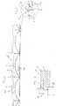
Figure 1 shows in cross section a floor 1 made ofblocks 2, equidistantly arranged horizontal beams 3 and a layer ofconcrete 4 which covers theblocks 2 and beams 3. At both lateral sides the beams 3 are provided withsupport surfaces 5 for supporting theblocks 2. The hardenedconcrete layer 4 structurally connects the beams 3 and cooperates with the beams 3 to function as a single structural unit. The ends of the beams 3 are supported by parts of the buildings construction or foundation (not shown).- As is particularly clear from
Figure 2 the beams 3 are formed from a steel sheet material 31 folded to form a beam with the desired cross section. The steel sheet 31 is galvanized to form a protective zinc layer. The ends 32, 33 of the sheet metal 31 overlap and are connected, e.g., by welding, spot welding, rivet, dowel or clinch connections. In the final floor the connected ends 32, 33 of the metal sheet 31 are fully embedded within theconcrete layer 4. This way, the connected ends 32, 33 are effectively protected against corrosion. Also the outer beam ends (not shown) of the beams 3 are fully embedded in theconcrete layer 4. These ends are typically not or not fully protected by galvanization. The embedding concrete protects these beam ends against corrosion. - In cross section the beams 3 enclose an upper hollow space 34 and a lower
hollow space 35. Bothhollow spaces 34, 35 extend in longitudinal direction of the beam 3 over the full length of the beam 3. - The upper hollow space 34 is triangular in cross section and comprises an
upper surface 36 which is substantially horizontal in use and two symmetrically arrangedside walls - The lower
hollow space 35 comprises alower surface 39 which is substantially horizontal in use and two symmetrically arrangedside walls lower surface 39 and under a 90 degrees angle with each other. Thelower surface 39 of the lowerhollow space 35 borders thelower side 42 of the beam 3. - The
lower side 42 of the beam 3 extends at both lateral sides of thelower surface 39 of the lowerhollow space 35 to form the support surfaces 5 for supporting theblocks 2. Thelower surface 39 of the lowerhollow space 35 forms the middle section of thelower side 42 of the beam 3 and spans about 10 - 50 %, e.g., about 25 - 40 %, e.g., about one third of thelower side 42. - The 90 degrees
angular points 43, 44 of the upper and lowerhollow spaces 34, 35 point towards each other. Aweb 45 connects these twopoints 43, 44. In use theweb 45 is substantially vertical. The cross section of the beam 3 is substantially symmetrical, with a symmetry axis coinciding with the vertical axis of theweb 45. - In the shown embodiment the upper hollow space 34 is larger than the lower
hollow space 35. For instance, the width of theupper surface 36 of the upper hollow space 34 can be about 1,5 - 3 times, e.g. about 2 times the width of thelower surface 39 of the lowerhollow space 35. - The
web 45 comprises alower section 46 and anupper section 47. In use thelower section 46 is located between twoadjacent blocks 2, while theupper section 47 is embedded in theconcrete layer 4. The overlapping ends 32, 33 of the metal sheet 31 are positioned in theupper section 47 of theweb 45. To enhance structural cooperation between theconcrete layer 4 and the beam 3, theupper section 47 of theweb 45 is provided with local deformations, such asspherical impressions 48. - The top surfaces 36 of the beams 3 protrude above the
blocks 2. Ametallic reinforcement mesh 49 rests on thetop surfaces 36 of the beams 3 (seeFigure 1 ). Themesh 49 is fully embedded in theconcrete layer 4. - The disclosed geometry makes it possible to use beams 3 weighing 7,5 kg/m or even less and still having sufficient load capacity avoiding the need to use auxiliary supports during assembly of the floor. The load capacity of the beams 3 can be sufficient to allow workmen to walk over the
blocks 2 resting on the support surfaces 5 of the beams 3 before the concrete is poured. Hence, during assembly the beams 3 only need to be supported at positions where the final floor is supported after hardening. - The
blocks 2 are made of an isolating material, such as expanded polystyrene, EPS. Theblocks 2 comprises amiddle section 21 with a rectangular cross section bordered by two downwardly slantinglongitudinal edges shoulder 24 resting on the support surfaces 5 of the beans 3. Onelongitudinal side 22 is provided with alateral extension 25 extending below theshoulder 24, fully covering thelower side 42 of the beam 3 and abutting the lower side of the slantingedge 23 of andadjacent block 2. This way, the isolation layer formed by theblocks 2 is not interrupted by the beams 3 and the formation of thermal bridges can effectively be prevented. - The floor 1 is finished with a screed
top layer 26. - As shown in
Figure 3 the outer end 27 of the beam rests on a foundation 28 where it faces a wall section 29. A gap 30 between the outer end 27 and the wall section 29 ensures that the outer end 27 of the beam 3 is fully embedded in theconcrete layer 4. Figure 4 shows an alternative embodiment of afloor 50 according to the invention. Parts which are the same as in the embodiment ofFigure 1 are indicated with the same referential numbers. Beams 3 comprisesupport surfaces 5 carrying blocks 51 formed bycurved shells 51, e.g., of a concrete or plastic material. Theshells 51 and beams 3 are covered by aconcrete layer 4 finished by a screedtop layer 25. As shown in more detail inFigure 5 , thelower side surface 39 of the lowerhollow space 35 of the beams 3 is provided with fastening elements 52 for a ceiling element 53. Optionally, thelower surface 39 can also be used for fastening other constructional elements, such as piping and the like. In the drawing ofFigure 4 pipe lines 54 are arranged between the ceiling 53 and theshells 51.
Claims (10)
- Floor (1) comprising blocks (2), beams (3) provided with support surfaces (5) for supporting the blocks and a layer (4) of concrete structurally connecting the beams and covering the blocks,characterized in that the beams are formed from a metal sheet (31) folded to form a beam with the desired cross section, wherein the cross sectional ends (32, 33) of the metal sheet overlap each other and are connected to each other, the ends being embedded in the concrete.
- Floor according to claim 1 wherein the outer ends (27) of the beams are embedded in the concrete.
- Floor according to claim 1 or 2 wherein the ends (32, 33) of the metal sheet are connected by means of a weld, spot welds, dowels, rivets and/or clinch connections.
- Floor according to any one of the preceding claims wherein the metal sheet (31) is provided with a protective layer, e.g., a zinc layer.
- Floor according to any one of the preceding claims wherein at least a part of the beams (3) enclose in cross section one or more hollow spaces (34, 35) extending in longitudinal direction of the beam, wherein a wall of at least one of the hollow spaces borders the lower side of the beam.
- Floor according to claim 5 wherein the lower side of the beam (3) is provided with fastening means.
- Floor according to any one of the preceding claims wherein one or more of the parts of the beams embedded in the concrete are provided with impressions (48).
- Floor according to any one of the preceding claims wherein the top sides of the beams (36) protrude above the blocks and wherein one or more reinforcement meshes rest on the top sides of the beams.
- Method of manufacturing a floor (1) according to any one of the preceding claims wherein beams (3) are used formed of a single metal sheet (31) folded to form a beam with a desired cross section, wherein the ends (34, 35) of the metal sheet overlap each other, the ends being embedded in the concrete.
- Method according to claim 9 wherein beams (3) are used weighing at most 7,5 kg/m, preferably less than 7 kg/m, wherein during assembly of the floor (1) the beams are only supported at positions where the final floor is supported after hardening.
Priority Applications (3)
| Application Number | Priority Date | Filing Date | Title |
|---|---|---|---|
| DK11167119.4TDK2527554T3 (en) | 2011-05-23 | 2011-05-23 | Beam and block floor |
| EP15159013.0AEP2899328A3 (en) | 2011-05-23 | 2011-05-23 | Beam and block floor |
| EP20110167119EP2527554B1 (en) | 2011-05-23 | 2011-05-23 | Beam and block floor |
Applications Claiming Priority (1)
| Application Number | Priority Date | Filing Date | Title |
|---|---|---|---|
| EP20110167119EP2527554B1 (en) | 2011-05-23 | 2011-05-23 | Beam and block floor |
Related Child Applications (1)
| Application Number | Title | Priority Date | Filing Date |
|---|---|---|---|
| EP15159013.0ADivisionEP2899328A3 (en) | 2011-05-23 | 2011-05-23 | Beam and block floor |
Publications (2)
| Publication Number | Publication Date |
|---|---|
| EP2527554A1 EP2527554A1 (en) | 2012-11-28 |
| EP2527554B1true EP2527554B1 (en) | 2015-03-18 |
Family
ID=44654558
Family Applications (2)
| Application Number | Title | Priority Date | Filing Date |
|---|---|---|---|
| EP15159013.0AWithdrawnEP2899328A3 (en) | 2011-05-23 | 2011-05-23 | Beam and block floor |
| EP20110167119RevokedEP2527554B1 (en) | 2011-05-23 | 2011-05-23 | Beam and block floor |
Family Applications Before (1)
| Application Number | Title | Priority Date | Filing Date |
|---|---|---|---|
| EP15159013.0AWithdrawnEP2899328A3 (en) | 2011-05-23 | 2011-05-23 | Beam and block floor |
Country Status (2)
| Country | Link |
|---|---|
| EP (2) | EP2899328A3 (en) |
| DK (1) | DK2527554T3 (en) |
Citations (8)
| Publication number | Priority date | Publication date | Assignee | Title |
|---|---|---|---|---|
| DE821703C (en) | 1949-10-30 | 1951-11-19 | Boelkow Ludwig | Composite ceiling |
| FR1127798A (en) | 1955-07-20 | 1956-12-24 | Floor | |
| FR1172553A (en)* | 1956-11-22 | 1959-02-11 | Prefabricated joist and slab floor | |
| US3256670A (en) | 1962-07-23 | 1966-06-21 | Tersigni Ennio | Prefabricated steel joist adapted for the reinforcement of floors |
| AT377302B (en)* | 1979-12-21 | 1985-03-11 | Hutter & Schranz Bautech | Prefabricated building elements for ceilings, roofs or walls |
| US4507901A (en) | 1974-04-04 | 1985-04-02 | Carroll Frank E | Sheet metal structural shape and use in building structures |
| NL1012339C2 (en) | 1999-06-15 | 2000-12-18 | Aannemersbedrijf Proper B V | Floor, preferably a renovation floor for buildings, contains lightweight support beams comprising a fibrous material embedded in a polymer matrix |
| WO2009109893A2 (en) | 2008-03-04 | 2009-09-11 | Angelo Candiracci | Panel for the construction of a structure resistant to bending such as a floor or the like |
Family Cites Families (4)
| Publication number | Priority date | Publication date | Assignee | Title |
|---|---|---|---|---|
| CH361384A (en)* | 1959-06-13 | 1962-04-15 | Coat Jean Paul | Ceiling construction method and element for its implementation |
| US5535569A (en)* | 1992-03-06 | 1996-07-16 | Bhp Steel (Jla) Pty, Ltd. | Sheet metal structural member and frames incorporating same |
| AU2004200915A1 (en) | 2003-03-13 | 2004-09-30 | Charlwood, Jennifer Marie | A Beam and a Method of Forming Same |
| AU2010273176A1 (en)* | 2009-07-14 | 2012-02-02 | Holdip Pty Ltd | Building floor structure and process for forming same |
- 2011
- 2011-05-23EPEP15159013.0Apatent/EP2899328A3/ennot_activeWithdrawn
- 2011-05-23EPEP20110167119patent/EP2527554B1/ennot_activeRevoked
- 2011-05-23DKDK11167119.4Tpatent/DK2527554T3/enactive
Patent Citations (8)
| Publication number | Priority date | Publication date | Assignee | Title |
|---|---|---|---|---|
| DE821703C (en) | 1949-10-30 | 1951-11-19 | Boelkow Ludwig | Composite ceiling |
| FR1127798A (en) | 1955-07-20 | 1956-12-24 | Floor | |
| FR1172553A (en)* | 1956-11-22 | 1959-02-11 | Prefabricated joist and slab floor | |
| US3256670A (en) | 1962-07-23 | 1966-06-21 | Tersigni Ennio | Prefabricated steel joist adapted for the reinforcement of floors |
| US4507901A (en) | 1974-04-04 | 1985-04-02 | Carroll Frank E | Sheet metal structural shape and use in building structures |
| AT377302B (en)* | 1979-12-21 | 1985-03-11 | Hutter & Schranz Bautech | Prefabricated building elements for ceilings, roofs or walls |
| NL1012339C2 (en) | 1999-06-15 | 2000-12-18 | Aannemersbedrijf Proper B V | Floor, preferably a renovation floor for buildings, contains lightweight support beams comprising a fibrous material embedded in a polymer matrix |
| WO2009109893A2 (en) | 2008-03-04 | 2009-09-11 | Angelo Candiracci | Panel for the construction of a structure resistant to bending such as a floor or the like |
Also Published As
| Publication number | Publication date |
|---|---|
| EP2899328A2 (en) | 2015-07-29 |
| EP2899328A3 (en) | 2015-08-12 |
| DK2527554T3 (en) | 2015-06-15 |
| EP2527554A1 (en) | 2012-11-28 |
Similar Documents
| Publication | Publication Date | Title |
|---|---|---|
| JP2646293B2 (en) | Sheet metal structural member, structural panel and construction method | |
| US8549805B2 (en) | Grid-type drop-panel structure, and a construction method therefor | |
| WO2010132900A1 (en) | Steel reinforcement structure of bubbledeck slab elements and procedure of manufacturing bubbledeck slab elements | |
| KR200414349Y1 (en) | Connection structure of precast concrete structure | |
| CN110777996A (en) | A composite steel truss composite board | |
| KR101650431B1 (en) | Precast wide composite girder with built up steel beam and prestressed concrete | |
| EP2527554B1 (en) | Beam and block floor | |
| KR200383490Y1 (en) | System for constructing composite reinforced concrete girders and beams using FRP | |
| KR102107666B1 (en) | Long Span Composite Beam And Long Span Structure Construction Method Using The Same | |
| CA2625897A1 (en) | Reinforced concrete forming system | |
| JP5729566B2 (en) | Method for forming shear reinforcement of concrete slab, road slab and flat slab | |
| US9464437B1 (en) | Precast I-beam concrete panels | |
| EP0555232B1 (en) | Connector beam | |
| KR100202270B1 (en) | Deck panels of reinforced concrete slabs | |
| WO2008064436A1 (en) | Metal joint allowing expansion and transfer of vertical loads between adjacent concrete slabs | |
| EP3348732B2 (en) | Support for a hollow-core slab | |
| JP6961408B2 (en) | Precast concrete boards and concrete structural slabs | |
| KR200383489Y1 (en) | System for constructing composite reinforced concrete girders and beams using FRP | |
| KR100424321B1 (en) | Deck panel for the slab of architecture which equipped steel wire | |
| KR100579543B1 (en) | Composite reinforced concrete beam construction system using FRP structure used as permanent structure | |
| KR100588350B1 (en) | Method of constructing the side end of median side of bridge slab and upper bracket applied to it | |
| JP7368671B2 (en) | Slab base structure before concrete pouring, reinforced concrete slab structure, construction method for slab base structure before concrete pouring, and construction method for reinforced concrete slab structure | |
| KR20100033695A (en) | Multi tee slab for structure construction | |
| KR200216265Y1 (en) | Deck panel for the slab of architecture which equipped steel wire | |
| KR930005630B1 (en) | Assembling slab of building |
Legal Events
| Date | Code | Title | Description |
|---|---|---|---|
| PUAI | Public reference made under article 153(3) epc to a published international application that has entered the european phase | Free format text:ORIGINAL CODE: 0009012 | |
| AK | Designated contracting states | Kind code of ref document:A1 Designated state(s):AL AT BE BG CH CY CZ DE DK EE ES FI FR GB GR HR HU IE IS IT LI LT LU LV MC MK MT NL NO PL PT RO RS SE SI SK SM TR | |
| AX | Request for extension of the european patent | Extension state:BA ME | |
| 17P | Request for examination filed | Effective date:20130527 | |
| RBV | Designated contracting states (corrected) | Designated state(s):AL AT BE BG CH CY CZ DE DK EE ES FI FR GB GR HR HU IE IS IT LI LT LU LV MC MK MT NL NO PL PT RO RS SE SI SK SM TR | |
| 17Q | First examination report despatched | Effective date:20130624 | |
| TPAC | Observations filed by third parties | Free format text:ORIGINAL CODE: EPIDOSNTIPA | |
| GRAP | Despatch of communication of intention to grant a patent | Free format text:ORIGINAL CODE: EPIDOSNIGR1 | |
| GRAS | Grant fee paid | Free format text:ORIGINAL CODE: EPIDOSNIGR3 | |
| TPAC | Observations filed by third parties | Free format text:ORIGINAL CODE: EPIDOSNTIPA | |
| INTG | Intention to grant announced | Effective date:20150120 | |
| GRAA | (expected) grant | Free format text:ORIGINAL CODE: 0009210 | |
| AK | Designated contracting states | Kind code of ref document:B1 Designated state(s):AL AT BE BG CH CY CZ DE DK EE ES FI FR GB GR HR HU IE IS IT LI LT LU LV MC MK MT NL NO PL PT RO RS SE SI SK SM TR | |
| REG | Reference to a national code | Ref country code:GB Ref legal event code:FG4D | |
| REG | Reference to a national code | Ref country code:CH Ref legal event code:EP | |
| REG | Reference to a national code | Ref country code:IE Ref legal event code:FG4D | |
| REG | Reference to a national code | Ref country code:AT Ref legal event code:REF Ref document number:716682 Country of ref document:AT Kind code of ref document:T Effective date:20150415 | |
| REG | Reference to a national code | Ref country code:DE Ref legal event code:R096 Ref document number:602011014719 Country of ref document:DE Effective date:20150430 | |
| REG | Reference to a national code | Ref country code:DK Ref legal event code:T3 Effective date:20150611 | |
| REG | Reference to a national code | Ref country code:FR Ref legal event code:PLFP Year of fee payment:5 | |
| REG | Reference to a national code | Ref country code:NL Ref legal event code:T3 | |
| PG25 | Lapsed in a contracting state [announced via postgrant information from national office to epo] | Ref country code:LT Free format text:LAPSE BECAUSE OF FAILURE TO SUBMIT A TRANSLATION OF THE DESCRIPTION OR TO PAY THE FEE WITHIN THE PRESCRIBED TIME-LIMIT Effective date:20150318 Ref country code:FI Free format text:LAPSE BECAUSE OF FAILURE TO SUBMIT A TRANSLATION OF THE DESCRIPTION OR TO PAY THE FEE WITHIN THE PRESCRIBED TIME-LIMIT Effective date:20150318 Ref country code:NO Free format text:LAPSE BECAUSE OF FAILURE TO SUBMIT A TRANSLATION OF THE DESCRIPTION OR TO PAY THE FEE WITHIN THE PRESCRIBED TIME-LIMIT Effective date:20150618 Ref country code:SE Free format text:LAPSE BECAUSE OF FAILURE TO SUBMIT A TRANSLATION OF THE DESCRIPTION OR TO PAY THE FEE WITHIN THE PRESCRIBED TIME-LIMIT Effective date:20150318 Ref country code:HR Free format text:LAPSE BECAUSE OF FAILURE TO SUBMIT A TRANSLATION OF THE DESCRIPTION OR TO PAY THE FEE WITHIN THE PRESCRIBED TIME-LIMIT Effective date:20150318 | |
| REG | Reference to a national code | Ref country code:AT Ref legal event code:MK05 Ref document number:716682 Country of ref document:AT Kind code of ref document:T Effective date:20150318 | |
| REG | Reference to a national code | Ref country code:LT Ref legal event code:MG4D | |
| PG25 | Lapsed in a contracting state [announced via postgrant information from national office to epo] | Ref country code:LV Free format text:LAPSE BECAUSE OF FAILURE TO SUBMIT A TRANSLATION OF THE DESCRIPTION OR TO PAY THE FEE WITHIN THE PRESCRIBED TIME-LIMIT Effective date:20150318 Ref country code:RS Free format text:LAPSE BECAUSE OF FAILURE TO SUBMIT A TRANSLATION OF THE DESCRIPTION OR TO PAY THE FEE WITHIN THE PRESCRIBED TIME-LIMIT Effective date:20150318 Ref country code:GR Free format text:LAPSE BECAUSE OF FAILURE TO SUBMIT A TRANSLATION OF THE DESCRIPTION OR TO PAY THE FEE WITHIN THE PRESCRIBED TIME-LIMIT Effective date:20150619 | |
| PG25 | Lapsed in a contracting state [announced via postgrant information from national office to epo] | Ref country code:RO Free format text:LAPSE BECAUSE OF FAILURE TO SUBMIT A TRANSLATION OF THE DESCRIPTION OR TO PAY THE FEE WITHIN THE PRESCRIBED TIME-LIMIT Effective date:20150318 Ref country code:EE Free format text:LAPSE BECAUSE OF FAILURE TO SUBMIT A TRANSLATION OF THE DESCRIPTION OR TO PAY THE FEE WITHIN THE PRESCRIBED TIME-LIMIT Effective date:20150318 Ref country code:ES Free format text:LAPSE BECAUSE OF FAILURE TO SUBMIT A TRANSLATION OF THE DESCRIPTION OR TO PAY THE FEE WITHIN THE PRESCRIBED TIME-LIMIT Effective date:20150318 Ref country code:PT Free format text:LAPSE BECAUSE OF FAILURE TO SUBMIT A TRANSLATION OF THE DESCRIPTION OR TO PAY THE FEE WITHIN THE PRESCRIBED TIME-LIMIT Effective date:20150720 Ref country code:CZ Free format text:LAPSE BECAUSE OF FAILURE TO SUBMIT A TRANSLATION OF THE DESCRIPTION OR TO PAY THE FEE WITHIN THE PRESCRIBED TIME-LIMIT Effective date:20150318 Ref country code:SK Free format text:LAPSE BECAUSE OF FAILURE TO SUBMIT A TRANSLATION OF THE DESCRIPTION OR TO PAY THE FEE WITHIN THE PRESCRIBED TIME-LIMIT Effective date:20150318 | |
| PG25 | Lapsed in a contracting state [announced via postgrant information from national office to epo] | Ref country code:IS Free format text:LAPSE BECAUSE OF FAILURE TO SUBMIT A TRANSLATION OF THE DESCRIPTION OR TO PAY THE FEE WITHIN THE PRESCRIBED TIME-LIMIT Effective date:20150718 Ref country code:AT Free format text:LAPSE BECAUSE OF FAILURE TO SUBMIT A TRANSLATION OF THE DESCRIPTION OR TO PAY THE FEE WITHIN THE PRESCRIBED TIME-LIMIT Effective date:20150318 Ref country code:PL Free format text:LAPSE BECAUSE OF FAILURE TO SUBMIT A TRANSLATION OF THE DESCRIPTION OR TO PAY THE FEE WITHIN THE PRESCRIBED TIME-LIMIT Effective date:20150318 | |
| REG | Reference to a national code | Ref country code:DE Ref legal event code:R026 Ref document number:602011014719 Country of ref document:DE | |
| PLBI | Opposition filed | Free format text:ORIGINAL CODE: 0009260 | |
| PG25 | Lapsed in a contracting state [announced via postgrant information from national office to epo] | Ref country code:IT Free format text:LAPSE BECAUSE OF FAILURE TO SUBMIT A TRANSLATION OF THE DESCRIPTION OR TO PAY THE FEE WITHIN THE PRESCRIBED TIME-LIMIT Effective date:20150318 | |
| REG | Reference to a national code | Ref country code:CH Ref legal event code:PL | |
| PLAX | Notice of opposition and request to file observation + time limit sent | Free format text:ORIGINAL CODE: EPIDOSNOBS2 | |
| 26 | Opposition filed | Opponent name:HAVEBO B.V. Effective date:20151218 | |
| PG25 | Lapsed in a contracting state [announced via postgrant information from national office to epo] | Ref country code:LI Free format text:LAPSE BECAUSE OF NON-PAYMENT OF DUE FEES Effective date:20150531 Ref country code:LU Free format text:LAPSE BECAUSE OF FAILURE TO SUBMIT A TRANSLATION OF THE DESCRIPTION OR TO PAY THE FEE WITHIN THE PRESCRIBED TIME-LIMIT Effective date:20150523 Ref country code:CH Free format text:LAPSE BECAUSE OF NON-PAYMENT OF DUE FEES Effective date:20150531 Ref country code:MC Free format text:LAPSE BECAUSE OF FAILURE TO SUBMIT A TRANSLATION OF THE DESCRIPTION OR TO PAY THE FEE WITHIN THE PRESCRIBED TIME-LIMIT Effective date:20150318 | |
| REG | Reference to a national code | Ref country code:IE Ref legal event code:MM4A | |
| PG25 | Lapsed in a contracting state [announced via postgrant information from national office to epo] | Ref country code:SI Free format text:LAPSE BECAUSE OF FAILURE TO SUBMIT A TRANSLATION OF THE DESCRIPTION OR TO PAY THE FEE WITHIN THE PRESCRIBED TIME-LIMIT Effective date:20150318 | |
| PG25 | Lapsed in a contracting state [announced via postgrant information from national office to epo] | Ref country code:IE Free format text:LAPSE BECAUSE OF NON-PAYMENT OF DUE FEES Effective date:20150523 | |
| REG | Reference to a national code | Ref country code:FR Ref legal event code:PLFP Year of fee payment:6 | |
| PLBB | Reply of patent proprietor to notice(s) of opposition received | Free format text:ORIGINAL CODE: EPIDOSNOBS3 | |
| REG | Reference to a national code | Ref country code:DE Ref legal event code:R231 Ref document number:602011014719 Country of ref document:DE | |
| PGFP | Annual fee paid to national office [announced via postgrant information from national office to epo] | Ref country code:GB Payment date:20160527 Year of fee payment:6 Ref country code:DE Payment date:20160527 Year of fee payment:6 | |
| REG | Reference to a national code | Ref country code:DK Ref legal event code:EAP Effective date:20160706 | |
| PGFP | Annual fee paid to national office [announced via postgrant information from national office to epo] | Ref country code:BE Payment date:20160527 Year of fee payment:6 Ref country code:NL Payment date:20160531 Year of fee payment:6 Ref country code:DK Payment date:20160525 Year of fee payment:6 Ref country code:FR Payment date:20160530 Year of fee payment:6 | |
| REG | Reference to a national code | Ref country code:GB Ref legal event code:S29 Free format text:OFFER FILED; APPLICATION FILED ON 31 AUGUST 2016 | |
| PG25 | Lapsed in a contracting state [announced via postgrant information from national office to epo] | Ref country code:DE Free format text:LAPSE BECAUSE OF THE APPLICANT RENOUNCES Effective date:20160719 | |
| REG | Reference to a national code | Ref country code:GB Ref legal event code:S29 Free format text:OFFER ACCEPTED | |
| REG | Reference to a national code | Ref country code:NL Ref legal event code:MA Free format text:SURRENDER, TOTAL - RENUNCIATION Effective date:20161125 | |
| PG25 | Lapsed in a contracting state [announced via postgrant information from national office to epo] | Ref country code:MT Free format text:LAPSE BECAUSE OF FAILURE TO SUBMIT A TRANSLATION OF THE DESCRIPTION OR TO PAY THE FEE WITHIN THE PRESCRIBED TIME-LIMIT Effective date:20150318 | |
| PG25 | Lapsed in a contracting state [announced via postgrant information from national office to epo] | Ref country code:NL Free format text:LAPSE BECAUSE OF THE APPLICANT RENOUNCES Effective date:20150318 Ref country code:DK Free format text:LAPSE BECAUSE OF THE APPLICANT RENOUNCES Effective date:20160706 Ref country code:GB Free format text:LAPSE BECAUSE OF THE APPLICANT RENOUNCES Effective date:20161207 | |
| RDAF | Communication despatched that patent is revoked | Free format text:ORIGINAL CODE: EPIDOSNREV1 | |
| STAA | Information on the status of an ep patent application or granted ep patent | Free format text:STATUS: THE PATENT HAS BEEN GRANTED | |
| REG | Reference to a national code | Ref country code:DE Ref legal event code:R064 Ref document number:602011014719 Country of ref document:DE Ref country code:DE Ref legal event code:R103 Ref document number:602011014719 Country of ref document:DE | |
| PG25 | Lapsed in a contracting state [announced via postgrant information from national office to epo] | Ref country code:SM Free format text:LAPSE BECAUSE OF FAILURE TO SUBMIT A TRANSLATION OF THE DESCRIPTION OR TO PAY THE FEE WITHIN THE PRESCRIBED TIME-LIMIT Effective date:20150318 Ref country code:BG Free format text:LAPSE BECAUSE OF FAILURE TO SUBMIT A TRANSLATION OF THE DESCRIPTION OR TO PAY THE FEE WITHIN THE PRESCRIBED TIME-LIMIT Effective date:20150318 Ref country code:HU Free format text:LAPSE BECAUSE OF FAILURE TO SUBMIT A TRANSLATION OF THE DESCRIPTION OR TO PAY THE FEE WITHIN THE PRESCRIBED TIME-LIMIT; INVALID AB INITIO Effective date:20110523 | |
| PG25 | Lapsed in a contracting state [announced via postgrant information from national office to epo] | Ref country code:CY Free format text:LAPSE BECAUSE OF FAILURE TO SUBMIT A TRANSLATION OF THE DESCRIPTION OR TO PAY THE FEE WITHIN THE PRESCRIBED TIME-LIMIT Effective date:20150318 | |
| RDAG | Patent revoked | Free format text:ORIGINAL CODE: 0009271 | |
| 27W | Patent revoked | Effective date:20170415 | |
| PG25 | Lapsed in a contracting state [announced via postgrant information from national office to epo] | Ref country code:TR Free format text:LAPSE BECAUSE OF FAILURE TO SUBMIT A TRANSLATION OF THE DESCRIPTION OR TO PAY THE FEE WITHIN THE PRESCRIBED TIME-LIMIT Effective date:20150318 | |
| REG | Reference to a national code | Ref country code:BE Ref legal event code:FP Effective date:20150615 | |
| PG25 | Lapsed in a contracting state [announced via postgrant information from national office to epo] | Ref country code:AL Free format text:LAPSE BECAUSE OF FAILURE TO SUBMIT A TRANSLATION OF THE DESCRIPTION OR TO PAY THE FEE WITHIN THE PRESCRIBED TIME-LIMIT Effective date:20150318 | |
| STAA | Information on the status of an ep patent application or granted ep patent | Free format text:STATUS: PATENT REVOKED |