EP2526899B1 - Repositionable heart valve - Google Patents
Repositionable heart valveDownload PDFInfo
- Publication number
- EP2526899B1 EP2526899B1EP12179075.2AEP12179075AEP2526899B1EP 2526899 B1EP2526899 B1EP 2526899B1EP 12179075 AEP12179075 AEP 12179075AEP 2526899 B1EP2526899 B1EP 2526899B1
- Authority
- EP
- European Patent Office
- Prior art keywords
- anchor
- valve
- figures
- post
- actuator
- Prior art date
- Legal status (The legal status is an assumption and is not a legal conclusion. Google has not performed a legal analysis and makes no representation as to the accuracy of the status listed.)
- Expired - Lifetime
Links
- 210000003709heart valveAnatomy0.000titledescription56
- 210000001765aortic valveAnatomy0.000claimsabstractdescription40
- 230000007246mechanismEffects0.000claimsdescription95
- 230000000063preceeding effectEffects0.000claims4
- 210000004027cellAnatomy0.000description93
- 238000000034methodMethods0.000description50
- 239000000463materialSubstances0.000description27
- 230000033001locomotionEffects0.000description24
- 239000008280bloodSubstances0.000description22
- 210000004369bloodAnatomy0.000description22
- 210000001519tissueAnatomy0.000description22
- 230000005012migrationEffects0.000description21
- 238000013508migrationMethods0.000description21
- 230000002441reversible effectEffects0.000description20
- 210000000709aortaAnatomy0.000description17
- 229910001000nickel titaniumInorganic materials0.000description17
- 210000002216heartAnatomy0.000description14
- 230000002829reductive effectEffects0.000description14
- 238000010168coupling processMethods0.000description13
- 238000005859coupling reactionMethods0.000description13
- HLXZNVUGXRDIFK-UHFFFAOYSA-Nnickel titaniumChemical compound[Ti].[Ti].[Ti].[Ti].[Ti].[Ti].[Ti].[Ti].[Ti].[Ti].[Ti].[Ni].[Ni].[Ni].[Ni].[Ni].[Ni].[Ni].[Ni].[Ni].[Ni].[Ni].[Ni].[Ni].[Ni]HLXZNVUGXRDIFK-UHFFFAOYSA-N0.000description13
- 206010067171RegurgitationDiseases0.000description12
- 230000008878couplingEffects0.000description12
- 230000009467reductionEffects0.000description12
- 210000000746body regionAnatomy0.000description11
- 210000005240left ventricleAnatomy0.000description11
- 239000004744fabricSubstances0.000description10
- 230000006870functionEffects0.000description10
- 238000009998heat settingMethods0.000description10
- 230000002265preventionEffects0.000description10
- 230000004044responseEffects0.000description10
- 238000013459approachMethods0.000description9
- 230000017531blood circulationEffects0.000description9
- 230000008569processEffects0.000description9
- 239000012781shape memory materialSubstances0.000description9
- 229910001220stainless steelInorganic materials0.000description8
- 230000015572biosynthetic processEffects0.000description7
- 210000004115mitral valveAnatomy0.000description7
- 238000001356surgical procedureMethods0.000description7
- 239000002131composite materialSubstances0.000description6
- 239000007943implantSubstances0.000description6
- 239000010935stainless steelSubstances0.000description6
- 206010052904Musculoskeletal stiffnessDiseases0.000description5
- 238000004873anchoringMethods0.000description5
- 238000002399angioplastyMethods0.000description5
- 230000008901benefitEffects0.000description5
- 230000000903blocking effectEffects0.000description5
- 238000002513implantationMethods0.000description5
- 230000036961partial effectEffects0.000description5
- 239000006260foamSubstances0.000description4
- 238000001727in vivoMethods0.000description4
- 230000000670limiting effectEffects0.000description4
- 230000013011matingEffects0.000description4
- 229910052751metalInorganic materials0.000description4
- 239000002184metalSubstances0.000description4
- 229920000642polymerPolymers0.000description4
- 238000000926separation methodMethods0.000description4
- 238000009941weavingMethods0.000description4
- 229910000684Cobalt-chromeInorganic materials0.000description3
- 208000036829Device dislocationDiseases0.000description3
- FAPWRFPIFSIZLT-UHFFFAOYSA-MSodium chlorideChemical compound[Na+].[Cl-]FAPWRFPIFSIZLT-UHFFFAOYSA-M0.000description3
- WAIPAZQMEIHHTJ-UHFFFAOYSA-N[Cr].[Co]Chemical compound[Cr].[Co]WAIPAZQMEIHHTJ-UHFFFAOYSA-N0.000description3
- 210000003484anatomyAnatomy0.000description3
- 239000010952cobalt-chromeSubstances0.000description3
- 230000006835compressionEffects0.000description3
- 238000007906compressionMethods0.000description3
- 230000008602contractionEffects0.000description3
- 239000002872contrast mediaSubstances0.000description3
- 239000012528membraneSubstances0.000description3
- 239000011780sodium chlorideSubstances0.000description3
- 238000003466weldingMethods0.000description3
- 241000283690Bos taurusSpecies0.000description2
- 229910000639Spring steelInorganic materials0.000description2
- 229910000831SteelInorganic materials0.000description2
- 230000036772blood pressureEffects0.000description2
- 238000009954braidingMethods0.000description2
- 230000035602clottingEffects0.000description2
- 239000011248coating agentSubstances0.000description2
- 238000000576coating methodMethods0.000description2
- 238000013461designMethods0.000description2
- 239000003814drugSubstances0.000description2
- 229940079593drugDrugs0.000description2
- 230000003073embolic effectEffects0.000description2
- 238000005530etchingMethods0.000description2
- 238000002594fluoroscopyMethods0.000description2
- -1for exampleSubstances0.000description2
- 238000002695general anesthesiaMethods0.000description2
- 238000000227grindingMethods0.000description2
- 230000001788irregularEffects0.000description2
- 230000007774longtermEffects0.000description2
- 238000004519manufacturing processMethods0.000description2
- 229920001296polysiloxanePolymers0.000description2
- 238000012545processingMethods0.000description2
- 230000002035prolonged effectEffects0.000description2
- 238000011084recoveryMethods0.000description2
- 230000001105regulatory effectEffects0.000description2
- 239000012858resilient materialSubstances0.000description2
- 238000007789sealingMethods0.000description2
- 238000007493shaping processMethods0.000description2
- 239000010959steelSubstances0.000description2
- 230000007704transitionEffects0.000description2
- 238000012800visualizationMethods0.000description2
- 238000004804windingMethods0.000description2
- 206010067484Adverse reactionDiseases0.000description1
- 206010002091AnaesthesiaDiseases0.000description1
- OKTJSMMVPCPJKN-UHFFFAOYSA-NCarbonChemical compound[C]OKTJSMMVPCPJKN-UHFFFAOYSA-N0.000description1
- 239000004593EpoxySubstances0.000description1
- 241000283073Equus caballusSpecies0.000description1
- 102000010834Extracellular Matrix ProteinsHuman genes0.000description1
- 108010037362Extracellular Matrix ProteinsProteins0.000description1
- 206010016654FibrosisDiseases0.000description1
- 208000032843HemorrhageDiseases0.000description1
- 229920000271Kevlar®Polymers0.000description1
- 241001465754MetazoaSpecies0.000description1
- 208000031481Pathologic ConstrictionDiseases0.000description1
- 208000001647Renal InsufficiencyDiseases0.000description1
- 208000006011StrokeDiseases0.000description1
- 206010042434Sudden deathDiseases0.000description1
- 238000003848UV Light-CuringMethods0.000description1
- HZEWFHLRYVTOIW-UHFFFAOYSA-N[Ti].[Ni]Chemical compound[Ti].[Ni]HZEWFHLRYVTOIW-UHFFFAOYSA-N0.000description1
- 230000009471actionEffects0.000description1
- 239000000853adhesiveSubstances0.000description1
- 230000001070adhesive effectEffects0.000description1
- 230000006838adverse reactionEffects0.000description1
- 230000037005anaesthesiaEffects0.000description1
- 229940127219anticoagulant drugDrugs0.000description1
- 230000006793arrhythmiaEffects0.000description1
- 206010003119arrhythmiaDiseases0.000description1
- 230000004872arterial blood pressureEffects0.000description1
- 238000005452bendingMethods0.000description1
- 239000000560biocompatible materialSubstances0.000description1
- 208000034158bleedingDiseases0.000description1
- 230000000740bleeding effectEffects0.000description1
- 229910052799carbonInorganic materials0.000description1
- 230000000747cardiac effectEffects0.000description1
- 230000008859changeEffects0.000description1
- 210000000038chestAnatomy0.000description1
- 210000004351coronary vesselAnatomy0.000description1
- 230000003247decreasing effectEffects0.000description1
- 238000002716delivery methodMethods0.000description1
- 230000001419dependent effectEffects0.000description1
- 230000000916dilatatory effectEffects0.000description1
- 238000005516engineering processMethods0.000description1
- 210000002744extracellular matrixAnatomy0.000description1
- 239000000835fiberSubstances0.000description1
- 230000004761fibrosisEffects0.000description1
- 238000011049fillingMethods0.000description1
- 239000011521glassSubstances0.000description1
- PCHJSUWPFVWCPO-UHFFFAOYSA-NgoldChemical compound[Au]PCHJSUWPFVWCPO-UHFFFAOYSA-N0.000description1
- 229910052737goldInorganic materials0.000description1
- 239000010931goldSubstances0.000description1
- 230000035876healingEffects0.000description1
- 230000004217heart functionEffects0.000description1
- 239000000017hydrogelSubstances0.000description1
- 238000003384imaging methodMethods0.000description1
- 208000015181infectious diseaseDiseases0.000description1
- 208000014674injuryDiseases0.000description1
- 230000003993interactionEffects0.000description1
- 230000002452interceptive effectEffects0.000description1
- 230000000968intestinal effectEffects0.000description1
- 230000002427irreversible effectEffects0.000description1
- 239000004761kevlarSubstances0.000description1
- 201000006370kidney failureDiseases0.000description1
- 238000003698laser cuttingMethods0.000description1
- 238000011068loading methodMethods0.000description1
- 238000002690local anesthesiaMethods0.000description1
- 239000003550markerSubstances0.000description1
- 239000011159matrix materialSubstances0.000description1
- 238000002483medicationMethods0.000description1
- 229910001092metal group alloyInorganic materials0.000description1
- 239000007769metal materialSubstances0.000description1
- 238000002324minimally invasive surgeryMethods0.000description1
- 230000000116mitigating effectEffects0.000description1
- 208000010125myocardial infarctionDiseases0.000description1
- 210000004165myocardiumAnatomy0.000description1
- ORQBXQOJMQIAOY-UHFFFAOYSA-NnobeliumChemical compound[No]ORQBXQOJMQIAOY-UHFFFAOYSA-N0.000description1
- RVTZCBVAJQQJTK-UHFFFAOYSA-Noxygen(2-);zirconium(4+)Chemical compound[O-2].[O-2].[Zr+4]RVTZCBVAJQQJTK-UHFFFAOYSA-N0.000description1
- 210000003516pericardiumAnatomy0.000description1
- 239000004033plasticSubstances0.000description1
- HWLDNSXPUQTBOD-UHFFFAOYSA-Nplatinum-iridium alloyChemical compound[Ir].[Pt]HWLDNSXPUQTBOD-UHFFFAOYSA-N0.000description1
- 239000011148porous materialSubstances0.000description1
- 230000000541pulsatile effectEffects0.000description1
- 230000002040relaxant effectEffects0.000description1
- 230000008439repair processEffects0.000description1
- 230000000452restraining effectEffects0.000description1
- 238000009958sewingMethods0.000description1
- 238000005476solderingMethods0.000description1
- 230000036262stenosisEffects0.000description1
- 208000037804stenosisDiseases0.000description1
- 210000001562sternumAnatomy0.000description1
- 229920002994synthetic fiberPolymers0.000description1
- 210000004876tela submucosaAnatomy0.000description1
- 230000008733traumaEffects0.000description1
- 230000005641tunnelingEffects0.000description1
- 230000000007visual effectEffects0.000description1
- 238000005406washingMethods0.000description1
- XLYOFNOQVPJJNP-UHFFFAOYSA-NwaterSubstancesOXLYOFNOQVPJJNP-UHFFFAOYSA-N0.000description1
Images


Classifications
- A—HUMAN NECESSITIES
- A61—MEDICAL OR VETERINARY SCIENCE; HYGIENE
- A61F—FILTERS IMPLANTABLE INTO BLOOD VESSELS; PROSTHESES; DEVICES PROVIDING PATENCY TO, OR PREVENTING COLLAPSING OF, TUBULAR STRUCTURES OF THE BODY, e.g. STENTS; ORTHOPAEDIC, NURSING OR CONTRACEPTIVE DEVICES; FOMENTATION; TREATMENT OR PROTECTION OF EYES OR EARS; BANDAGES, DRESSINGS OR ABSORBENT PADS; FIRST-AID KITS
- A61F2/00—Filters implantable into blood vessels; Prostheses, i.e. artificial substitutes or replacements for parts of the body; Appliances for connecting them with the body; Devices providing patency to, or preventing collapsing of, tubular structures of the body, e.g. stents
- A61F2/02—Prostheses implantable into the body
- A61F2/24—Heart valves ; Vascular valves, e.g. venous valves; Heart implants, e.g. passive devices for improving the function of the native valve or the heart muscle; Transmyocardial revascularisation [TMR] devices; Valves implantable in the body
- A61F2/2412—Heart valves ; Vascular valves, e.g. venous valves; Heart implants, e.g. passive devices for improving the function of the native valve or the heart muscle; Transmyocardial revascularisation [TMR] devices; Valves implantable in the body with soft flexible valve members, e.g. tissue valves shaped like natural valves
- A61F2/2418—Scaffolds therefor, e.g. support stents
- A—HUMAN NECESSITIES
- A61—MEDICAL OR VETERINARY SCIENCE; HYGIENE
- A61F—FILTERS IMPLANTABLE INTO BLOOD VESSELS; PROSTHESES; DEVICES PROVIDING PATENCY TO, OR PREVENTING COLLAPSING OF, TUBULAR STRUCTURES OF THE BODY, e.g. STENTS; ORTHOPAEDIC, NURSING OR CONTRACEPTIVE DEVICES; FOMENTATION; TREATMENT OR PROTECTION OF EYES OR EARS; BANDAGES, DRESSINGS OR ABSORBENT PADS; FIRST-AID KITS
- A61F2/00—Filters implantable into blood vessels; Prostheses, i.e. artificial substitutes or replacements for parts of the body; Appliances for connecting them with the body; Devices providing patency to, or preventing collapsing of, tubular structures of the body, e.g. stents
- A61F2/02—Prostheses implantable into the body
- A61F2/24—Heart valves ; Vascular valves, e.g. venous valves; Heart implants, e.g. passive devices for improving the function of the native valve or the heart muscle; Transmyocardial revascularisation [TMR] devices; Valves implantable in the body
- A61F2/2409—Support rings therefor, e.g. for connecting valves to tissue
- A—HUMAN NECESSITIES
- A61—MEDICAL OR VETERINARY SCIENCE; HYGIENE
- A61F—FILTERS IMPLANTABLE INTO BLOOD VESSELS; PROSTHESES; DEVICES PROVIDING PATENCY TO, OR PREVENTING COLLAPSING OF, TUBULAR STRUCTURES OF THE BODY, e.g. STENTS; ORTHOPAEDIC, NURSING OR CONTRACEPTIVE DEVICES; FOMENTATION; TREATMENT OR PROTECTION OF EYES OR EARS; BANDAGES, DRESSINGS OR ABSORBENT PADS; FIRST-AID KITS
- A61F2/00—Filters implantable into blood vessels; Prostheses, i.e. artificial substitutes or replacements for parts of the body; Appliances for connecting them with the body; Devices providing patency to, or preventing collapsing of, tubular structures of the body, e.g. stents
- A61F2/02—Prostheses implantable into the body
- A61F2/24—Heart valves ; Vascular valves, e.g. venous valves; Heart implants, e.g. passive devices for improving the function of the native valve or the heart muscle; Transmyocardial revascularisation [TMR] devices; Valves implantable in the body
- A61F2/2427—Devices for manipulating or deploying heart valves during implantation
- A61F2/2439—Expansion controlled by filaments
- A—HUMAN NECESSITIES
- A61—MEDICAL OR VETERINARY SCIENCE; HYGIENE
- A61F—FILTERS IMPLANTABLE INTO BLOOD VESSELS; PROSTHESES; DEVICES PROVIDING PATENCY TO, OR PREVENTING COLLAPSING OF, TUBULAR STRUCTURES OF THE BODY, e.g. STENTS; ORTHOPAEDIC, NURSING OR CONTRACEPTIVE DEVICES; FOMENTATION; TREATMENT OR PROTECTION OF EYES OR EARS; BANDAGES, DRESSINGS OR ABSORBENT PADS; FIRST-AID KITS
- A61F2/00—Filters implantable into blood vessels; Prostheses, i.e. artificial substitutes or replacements for parts of the body; Appliances for connecting them with the body; Devices providing patency to, or preventing collapsing of, tubular structures of the body, e.g. stents
- A61F2/02—Prostheses implantable into the body
- A61F2/24—Heart valves ; Vascular valves, e.g. venous valves; Heart implants, e.g. passive devices for improving the function of the native valve or the heart muscle; Transmyocardial revascularisation [TMR] devices; Valves implantable in the body
- A61F2/2427—Devices for manipulating or deploying heart valves during implantation
- A61F2/243—Deployment by mechanical expansion
- A61F2/2433—Deployment by mechanical expansion using balloon catheter
- A—HUMAN NECESSITIES
- A61—MEDICAL OR VETERINARY SCIENCE; HYGIENE
- A61F—FILTERS IMPLANTABLE INTO BLOOD VESSELS; PROSTHESES; DEVICES PROVIDING PATENCY TO, OR PREVENTING COLLAPSING OF, TUBULAR STRUCTURES OF THE BODY, e.g. STENTS; ORTHOPAEDIC, NURSING OR CONTRACEPTIVE DEVICES; FOMENTATION; TREATMENT OR PROTECTION OF EYES OR EARS; BANDAGES, DRESSINGS OR ABSORBENT PADS; FIRST-AID KITS
- A61F2/00—Filters implantable into blood vessels; Prostheses, i.e. artificial substitutes or replacements for parts of the body; Appliances for connecting them with the body; Devices providing patency to, or preventing collapsing of, tubular structures of the body, e.g. stents
- A61F2/02—Prostheses implantable into the body
- A61F2/24—Heart valves ; Vascular valves, e.g. venous valves; Heart implants, e.g. passive devices for improving the function of the native valve or the heart muscle; Transmyocardial revascularisation [TMR] devices; Valves implantable in the body
- A61F2/2427—Devices for manipulating or deploying heart valves during implantation
- A61F2/2436—Deployment by retracting a sheath
- A—HUMAN NECESSITIES
- A61—MEDICAL OR VETERINARY SCIENCE; HYGIENE
- A61F—FILTERS IMPLANTABLE INTO BLOOD VESSELS; PROSTHESES; DEVICES PROVIDING PATENCY TO, OR PREVENTING COLLAPSING OF, TUBULAR STRUCTURES OF THE BODY, e.g. STENTS; ORTHOPAEDIC, NURSING OR CONTRACEPTIVE DEVICES; FOMENTATION; TREATMENT OR PROTECTION OF EYES OR EARS; BANDAGES, DRESSINGS OR ABSORBENT PADS; FIRST-AID KITS
- A61F2220/00—Fixations or connections for prostheses classified in groups A61F2/00 - A61F2/26 or A61F2/82 or A61F9/00 or A61F11/00 or subgroups thereof
- A61F2220/0008—Fixation appliances for connecting prostheses to the body
- A61F2220/0016—Fixation appliances for connecting prostheses to the body with sharp anchoring protrusions, e.g. barbs, pins, spikes
- A—HUMAN NECESSITIES
- A61—MEDICAL OR VETERINARY SCIENCE; HYGIENE
- A61F—FILTERS IMPLANTABLE INTO BLOOD VESSELS; PROSTHESES; DEVICES PROVIDING PATENCY TO, OR PREVENTING COLLAPSING OF, TUBULAR STRUCTURES OF THE BODY, e.g. STENTS; ORTHOPAEDIC, NURSING OR CONTRACEPTIVE DEVICES; FOMENTATION; TREATMENT OR PROTECTION OF EYES OR EARS; BANDAGES, DRESSINGS OR ABSORBENT PADS; FIRST-AID KITS
- A61F2220/00—Fixations or connections for prostheses classified in groups A61F2/00 - A61F2/26 or A61F2/82 or A61F9/00 or A61F11/00 or subgroups thereof
- A61F2220/0025—Connections or couplings between prosthetic parts, e.g. between modular parts; Connecting elements
- A61F2220/005—Connections or couplings between prosthetic parts, e.g. between modular parts; Connecting elements using adhesives
- A—HUMAN NECESSITIES
- A61—MEDICAL OR VETERINARY SCIENCE; HYGIENE
- A61F—FILTERS IMPLANTABLE INTO BLOOD VESSELS; PROSTHESES; DEVICES PROVIDING PATENCY TO, OR PREVENTING COLLAPSING OF, TUBULAR STRUCTURES OF THE BODY, e.g. STENTS; ORTHOPAEDIC, NURSING OR CONTRACEPTIVE DEVICES; FOMENTATION; TREATMENT OR PROTECTION OF EYES OR EARS; BANDAGES, DRESSINGS OR ABSORBENT PADS; FIRST-AID KITS
- A61F2220/00—Fixations or connections for prostheses classified in groups A61F2/00 - A61F2/26 or A61F2/82 or A61F9/00 or A61F11/00 or subgroups thereof
- A61F2220/0025—Connections or couplings between prosthetic parts, e.g. between modular parts; Connecting elements
- A61F2220/0058—Connections or couplings between prosthetic parts, e.g. between modular parts; Connecting elements soldered or brazed or welded
- A—HUMAN NECESSITIES
- A61—MEDICAL OR VETERINARY SCIENCE; HYGIENE
- A61F—FILTERS IMPLANTABLE INTO BLOOD VESSELS; PROSTHESES; DEVICES PROVIDING PATENCY TO, OR PREVENTING COLLAPSING OF, TUBULAR STRUCTURES OF THE BODY, e.g. STENTS; ORTHOPAEDIC, NURSING OR CONTRACEPTIVE DEVICES; FOMENTATION; TREATMENT OR PROTECTION OF EYES OR EARS; BANDAGES, DRESSINGS OR ABSORBENT PADS; FIRST-AID KITS
- A61F2220/00—Fixations or connections for prostheses classified in groups A61F2/00 - A61F2/26 or A61F2/82 or A61F9/00 or A61F11/00 or subgroups thereof
- A61F2220/0025—Connections or couplings between prosthetic parts, e.g. between modular parts; Connecting elements
- A61F2220/0075—Connections or couplings between prosthetic parts, e.g. between modular parts; Connecting elements sutured, ligatured or stitched, retained or tied with a rope, string, thread, wire or cable
- A—HUMAN NECESSITIES
- A61—MEDICAL OR VETERINARY SCIENCE; HYGIENE
- A61F—FILTERS IMPLANTABLE INTO BLOOD VESSELS; PROSTHESES; DEVICES PROVIDING PATENCY TO, OR PREVENTING COLLAPSING OF, TUBULAR STRUCTURES OF THE BODY, e.g. STENTS; ORTHOPAEDIC, NURSING OR CONTRACEPTIVE DEVICES; FOMENTATION; TREATMENT OR PROTECTION OF EYES OR EARS; BANDAGES, DRESSINGS OR ABSORBENT PADS; FIRST-AID KITS
- A61F2230/00—Geometry of prostheses classified in groups A61F2/00 - A61F2/26 or A61F2/82 or A61F9/00 or A61F11/00 or subgroups thereof
- A61F2230/0002—Two-dimensional shapes, e.g. cross-sections
- A61F2230/0028—Shapes in the form of latin or greek characters
- A61F2230/005—Rosette-shaped, e.g. star-shaped
- A—HUMAN NECESSITIES
- A61—MEDICAL OR VETERINARY SCIENCE; HYGIENE
- A61F—FILTERS IMPLANTABLE INTO BLOOD VESSELS; PROSTHESES; DEVICES PROVIDING PATENCY TO, OR PREVENTING COLLAPSING OF, TUBULAR STRUCTURES OF THE BODY, e.g. STENTS; ORTHOPAEDIC, NURSING OR CONTRACEPTIVE DEVICES; FOMENTATION; TREATMENT OR PROTECTION OF EYES OR EARS; BANDAGES, DRESSINGS OR ABSORBENT PADS; FIRST-AID KITS
- A61F2230/00—Geometry of prostheses classified in groups A61F2/00 - A61F2/26 or A61F2/82 or A61F9/00 or A61F11/00 or subgroups thereof
- A61F2230/0002—Two-dimensional shapes, e.g. cross-sections
- A61F2230/0028—Shapes in the form of latin or greek characters
- A61F2230/0054—V-shaped
- A—HUMAN NECESSITIES
- A61—MEDICAL OR VETERINARY SCIENCE; HYGIENE
- A61F—FILTERS IMPLANTABLE INTO BLOOD VESSELS; PROSTHESES; DEVICES PROVIDING PATENCY TO, OR PREVENTING COLLAPSING OF, TUBULAR STRUCTURES OF THE BODY, e.g. STENTS; ORTHOPAEDIC, NURSING OR CONTRACEPTIVE DEVICES; FOMENTATION; TREATMENT OR PROTECTION OF EYES OR EARS; BANDAGES, DRESSINGS OR ABSORBENT PADS; FIRST-AID KITS
- A61F2230/00—Geometry of prostheses classified in groups A61F2/00 - A61F2/26 or A61F2/82 or A61F9/00 or A61F11/00 or subgroups thereof
- A61F2230/0063—Three-dimensional shapes
- A61F2230/0065—Three-dimensional shapes toroidal, e.g. ring-shaped, doughnut-shaped
- A—HUMAN NECESSITIES
- A61—MEDICAL OR VETERINARY SCIENCE; HYGIENE
- A61F—FILTERS IMPLANTABLE INTO BLOOD VESSELS; PROSTHESES; DEVICES PROVIDING PATENCY TO, OR PREVENTING COLLAPSING OF, TUBULAR STRUCTURES OF THE BODY, e.g. STENTS; ORTHOPAEDIC, NURSING OR CONTRACEPTIVE DEVICES; FOMENTATION; TREATMENT OR PROTECTION OF EYES OR EARS; BANDAGES, DRESSINGS OR ABSORBENT PADS; FIRST-AID KITS
- A61F2230/00—Geometry of prostheses classified in groups A61F2/00 - A61F2/26 or A61F2/82 or A61F9/00 or A61F11/00 or subgroups thereof
- A61F2230/0063—Three-dimensional shapes
- A61F2230/0067—Three-dimensional shapes conical
- A—HUMAN NECESSITIES
- A61—MEDICAL OR VETERINARY SCIENCE; HYGIENE
- A61F—FILTERS IMPLANTABLE INTO BLOOD VESSELS; PROSTHESES; DEVICES PROVIDING PATENCY TO, OR PREVENTING COLLAPSING OF, TUBULAR STRUCTURES OF THE BODY, e.g. STENTS; ORTHOPAEDIC, NURSING OR CONTRACEPTIVE DEVICES; FOMENTATION; TREATMENT OR PROTECTION OF EYES OR EARS; BANDAGES, DRESSINGS OR ABSORBENT PADS; FIRST-AID KITS
- A61F2230/00—Geometry of prostheses classified in groups A61F2/00 - A61F2/26 or A61F2/82 or A61F9/00 or A61F11/00 or subgroups thereof
- A61F2230/0063—Three-dimensional shapes
- A61F2230/0073—Quadric-shaped
- A61F2230/0078—Quadric-shaped hyperboloidal
- A—HUMAN NECESSITIES
- A61—MEDICAL OR VETERINARY SCIENCE; HYGIENE
- A61F—FILTERS IMPLANTABLE INTO BLOOD VESSELS; PROSTHESES; DEVICES PROVIDING PATENCY TO, OR PREVENTING COLLAPSING OF, TUBULAR STRUCTURES OF THE BODY, e.g. STENTS; ORTHOPAEDIC, NURSING OR CONTRACEPTIVE DEVICES; FOMENTATION; TREATMENT OR PROTECTION OF EYES OR EARS; BANDAGES, DRESSINGS OR ABSORBENT PADS; FIRST-AID KITS
- A61F2250/00—Special features of prostheses classified in groups A61F2/00 - A61F2/26 or A61F2/82 or A61F9/00 or A61F11/00 or subgroups thereof
- A61F2250/0058—Additional features; Implant or prostheses properties not otherwise provided for
- A61F2250/006—Additional features; Implant or prostheses properties not otherwise provided for modular
Definitions
- the present inventionrelates to methods and apparatus for endovascularly replacing a heart valve. More particularly, the present invention relates to methods and apparatus for percutaneously replacing a heart valve with a replacement valve using an expandable and retrievable anchor.
- Heart valve surgeryis used to repair or replace diseased heart valves.
- Valve surgeryis an open-heart procedure conducted under general anesthesia. An incision is made through the patient's sternum (sternotomy), and the patient's heart is stopped while blood flow is rerouted through a heart-lung bypass machine.
- PVTPercutaneous Valve Technologies
- Fort Lee, New Jerseyhas developed a balloon-expandable stent integrated with a bioprosthetic valve.
- the stent/valve deviceis deployed across the native diseased valve to permanently hold the valve open, thereby alleviating a need to excise the native valve and to position the bioprosthetic valve in place of the native valve.
- PVT's deviceis designed for delivery in a cardiac catheterization laboratory under local anesthesia using fluoroscopic guidance, thereby avoiding general anesthesia and open-heart surgery. The device was first implanted in a patient in April of 2002.
- the present inventionis defined by an apparatus for replacing a native aortic valve as defined in claim 1.
- the dependent claimsdepict advantageous features of the present invention.
- the present inventionrelates to an apparatus for endovascularly or percutaneously delivering and deploying a prosthesis, e.g., an aortic prosthesis, within and/or across a patient's native heart valve, referred to hereinafter as replacing the patient's heart valve.
- a delivery system and/or deployment toolis provided including a sheath assembly and a guidewire for placing the prosthetic apparatus endovascularly within the patient and a user control allowing manipulation of the prosthetic apparatus from external to the patient through the application of a non-hydraulically expanding or non-pneumatically expanding force on the anchor.
- a hydraulically or pneumatically expanding forcewould be, for example, a force applied to the anchor by a balloon expanded within the anchor.
- the application of a non-hydraulically expanding or non-pneumatically expanding forcecould include the use of a hydraulic component transmitting a proximally or distally directed force on an anchor.
- the apparatusincludes an anchor and a replacement valve.
- the anchorincludes an expandable anchor such as a braid.
- the expandable braidincludes closed edges, but the edges may alternatively be open.
- the replacement valveis adapted to be secured within the anchor, and as such, be delivered endovascularly to the patient's heart to replace one of the patient's native heart valves. More preferably, the apparatus of the present invention contemplate replacement of the patient's aortic valve.
- Anchor 30preferably is fabricated by using self-expanding patterns (laser cut or chemically milled), braids, and materials, such as a stainless steel, nickel-titanium (“Nitinol”) or cobalt chromium but alternatively may be fabricated using balloon-expandable patterns where the anchor is designed to plastically deform to it's final shape by means of balloon expansion.
- Replacement valve 20is preferably from biologic tissues, e.g.
- Control actuators 50pass from a delivery system for apparatus 10 through female interlocking elements 42, through eyelets 45 of male interlocking elements 44, and back through female interlocking elements 42, such that a double strand of wire 50 passes through each female interlocking element 42 for manipulation by a medical practitioner external to the patient to actuate and control the anchor by changing the anchor's shape.
- Control actuators 50may comprise, for example, strands of suture or wire.
- Actuators 60are reversibly coupled to apparatus 10 and may be used in conjunction with actuators 50 to actuate anchor 30, e.g., to foreshorten and lock apparatus 10 in the fully deployed configuration. Actuators 60 also facilitate repositioning and retrieval of apparatus 10, as described hereinafter.
- anchor 30may be foreshortened and radially expanded by applying a distally directed force on actuators 60 while proximally retracting actuators 50.
- control actuators 62pass through interior lumens 61 of actuators 60. This ensures that actuators 60 are aligned properly with apparatus 10 during deployment and foreshortening.
- This anchoring forceis preferably 454g-907g (1 to 2 lbs), more preferably 907g-1810g (2 to 4 lbs), or more preferably 1810g-4540g (4 to 10 lbs). In some embodiments, the anchoring force is preferably greater than 454g (1 pound) more preferably greater than 907g (2 pounds), or more preferably greater than 1810g (4 pounds).
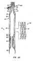
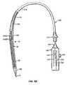
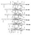
- a delivery and deployment system for a self-expanding embodiment of apparatus 10including a sheath 110 having a lumen 112.
- Self-expanding anchor 30is collapsible to a delivery configuration within lumen 112 of sheath 110, such that apparatus 10 may be delivered via delivery system 100.
- apparatus 10may be deployed from lumen 112 by retracting sheath 110 relative to apparatus 10, control actuators 50 and actuators 60, which causes anchor 30 to dynamically self-expand to a partially deployed configuration.
- Control actuators 50then are retracted relative to apparatus 10 and actuators 60 to impose foreshortening upon anchor 30, as seen in Figure 3B .
- actuators 60push against lip region 32 of anchor 30, while actuators 50 pull on posts 38 of the anchor.
- Actuators 62may be retracted along with actuators 50 to enhance the distally-directed pushing force applied by actuators 60 to lip region 32. Continued retraction of actuators 50 relative to actuators 60 would lock locks 40 and fully deploy apparatus 10 with replacement valve 20 properly seated within anchor 30, as in Figures IB and 2B.
- Apparatus 10comprises enhanced radial strength in the fully deployed configuration as compared to the partially deployed configuration of Figure 3 A . Once apparatus 10 has been fully deployed, actuators 50 and 62 may be removed from apparatus 10, thereby separating delivery system 100 including actuators 60 from the apparatus.
- control actuators 50are retracted while actuators 60 are advanced, thereby urging lip region 32 of anchor 30 in a distal direction while urging posts 38 of the anchor in a proximal direction.
- actuators 50have been pulled from eyelets 45 of male elements 44 of locks 40, actuators 60 are decoupled from anchor 30, e.g. via actuators 62, and delivery system 100 is removed from the patient, thereby completing deployment of apparatus 10.
- Optional barb elements 37engage the patient's native valve leaflets, e.g. to further preclude migration of the apparatus and/or reduce paravalvular regurgitation.
- inflatable member 130 within replacement valve 20is expected to reduce a delivery profile of the apparatus, as compared to previously known apparatus. This reduction may facilitate retrograde delivery and deployment of apparatus 10".
- pull actuators 50 and push actuators 60are manipulated from external to the patient to foreshorten anchor 30 and sufficiently expand lumen 31 of the anchor to facilitate advancement of inflatable member 130 within replacement valve 20. Also shown is the tip of an angioplasty catheter 130 being advanced through delivery system 110.
- sacs 200are provided as discrete sacs at different positions along the height of anchor 30.
- the sacsare provided as continuous cylinders at various heights.
- a single sacis provided with a cylindrical shape that spans multiple heights.
- the sacs of Figure 15Dare discrete, smaller and provided in larger quantities.
- Figure 15Eprovides a spiral sac. Alternative sac configurations will be apparent to those of skill in the art.
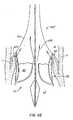
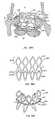
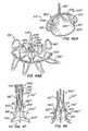
- FIGs 17 and 18show yet another alternative embodiment of the anchor lock.
- Anchor 300has a plurality of male interlocking elements 302 having eyelets 304 formed therein.
- Male interlocking elementsare connected to braided structure 300 by inter-weaving elements 302 (and 308) or alternatively suturing, soldering, welding, or connecting with adhesive.
- Valve commissures 24are connected to male interlocking elements 302 along their length.
- Replacement valve 20 annular base 22is connected to the distal end 34 of anchor 300 (or 30) as is illustrated in figures 1A and IB.
- Male interlocking elements 302also include holes 306 that mate with tabs 310 extending into holes 312 in female interlocking elements 308.
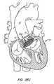
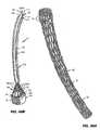
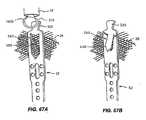
- FIG. 37A-Bisometric views, partially in section, further illustrate apparatus 450 in the fully deployed and expanded configuration.
- Figure 37Aillustrates the wireframe structure of anchor 470
- Figure 37Billustrates an embodiment of anchor 470 covered in a biocompatible material B. Placement of replacement valve 460 within apparatus 450 may be seen in Figure 37B .
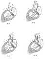
- the patient's native valveis captured between lip region 472 and skirt region 474 of anchor 470 in the fully deployed configuration (see Figure 38B ).
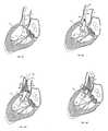
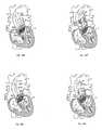
- apparatus 450is deployed from lumen 422 of sheath 420, for example, under fluoroscopic guidance, such that skirt section 474 is disposed within left ventricle LV, body section 476b is disposed across the patient's native valve leaflets L, and lip section 472 is disposed within the patient's aorta A.
- apparatus 450may be dynamically repositioned to obtain proper alignment with the anatomical landmarks.
- apparatus 450may be refracted within lumen 422 of sheath 420 via actuators 424, even after anchor 470 has dynamically expanded to the partially deployed configuration, for example, to abort the procedure or to reposition sheath 420.
- skirt region 474 of anchor 470is locked in the expanded configuration via skirt lock 490, as previously described with respect to Figures 36 .
- skirt region 474is maneuvered such that it engages the patient's valve annulus An and/or native valve leaflets L, thereby providing positive registration of apparatus 450 relative to the anatomical landmarks.
- Elements 424bare then actuated external to the patient in order to expand lip region 472, as previously described in Figures 35 .
- Lip region 472is locked in the expanded configuration via lip lock 480.
- deployment of apparatus 450is fully reversible until lip lock 480 and/or skirt lock 490 has been actuated.
- Elements 424are pulled from eyelets 483 and 493, and delivery system 410 is removed from the patient. As will be apparent, the order of expansion of lip region 472 and skirt region 474 may be reversed, concurrent, etc.
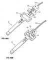
- Proximally-oriented annular bore 732 between inner tube 720 and middle distal tube 730is adapted to receive skirt section 580 and groove section 570 of anchor piece 550 in the reduced delivery configuration.
- Annular space 744 formed at the overlap between middle distal tube 730 and outer tube 740is adapted to receive lip section 560 of anchor piece 550 in the reduced delivery configuration.
- More proximal annular space 746 between inner tube 720 and outer tube 740may be adapted to receive replacement valve 610 and expandable frame 620 of valve piece 600 in the reduced delivery configuration.
- either anchor piece 550 or valve piece 600may be balloon expandable from the delivery configuration to the deployed configuration.
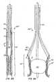
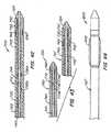
- Delivery system 800is adapted for delivery of an embodiment of apparatus 510 wherein the valve piece is balloon expandable. Additional delivery systems - both single and multi-catheter - for deployment of alternative combinations of balloon and self-expandable elements will be apparent to those of skill in the art in view of the illustrative delivery systems provided in Figures 42-44 .
- delivery system 800comprises delivery catheter 710".
- Delivery catheter 710is substantially equivalent to delivery catheter 710 of delivery system 700, except that catheter 710" does not comprise retainer elements 726, and annular space 746 does not receive the valve piece.
- catheter 710"comprises inflatable balloon 802 coupled to the exterior of outer tube 740", as well as an inflation lumen (not shown) for reversibly delivering an inflation medium from a proximal region of catheter 710" into the interior of inflatable balloon 802 for expanding the balloon from a delivery configuration to a deployed configuration.
- Valve piece 600may be crimped to the exterior of balloon 802 in the delivery configuration, then deployed and coupled to anchor piece 550 in vivo.
- Delivery catheter 710"preferably comprises radiopaque marker bands 804a and 804b disposed on either side of balloon 802 to facilitate proper positioning of valve piece 600 during deployment of the valve piece, for example, under fluoroscopic guidance.
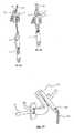
- Apparatus 510'comprising an alternative alignment/locking mechanism is described.
- Apparatus 510"is illustratively shown in conjunction with delivery system 700 described hereinabove with respect to Figure 42 .
- Valve piece 600"is shown partially deployed from outer tube 740 of catheter 710.
- replacement valve 610" of valve piece 600as well as inner tube 720 and middle distal tube 730 of delivery catheter 710, are not shown in Figure 47 .
- Female guides 672are translatable about male posts 670, but are constrained by flared ends 671 of the male posts. In this manner, anchor piece 550"' and valve piece 600"' remain coupled and in radial alignment with one another at all times - including delivery -but may be longitudinally separated from one another during delivery. This facilitates percutaneous delivery without requiring a transseptal approach, while mitigating a risk of inadvertent deployment of the anchor and valve pieces in an uncoupled configuration. Additional alignment/locking mechanisms will be apparent in view of the mechanisms described with respect to Figures 46-48 .
- Anchor actuation elements 106preferably comprise both proximal anchor actuation elements and distal anchor actuation elements.
- the proximal anchor actuation elementsmay, for example, comprise actuators 106a that are releasably coupled to a proximal region of anchor 30 of apparatus 10 via releasable attachment mechanisms for manipulating a proximal region of apparatus 10.
- the distal anchor actuation elementsmay comprise actuators 106b that are releasably coupled to a distal region of anchor 30 via releasable attachment mechanisms for manipulating the distal region of apparatus 10.
- the distal anchor actuation elementsmay comprise posts or anchor attachment elements 32 of anchor 30 and the releasable attachment mechanisms connecting actuators 106b to posts 32.
- anchor 30is formed from a collapsible and expandable wire braid.
- Anchor braid 30is preferably self-expanding and is preferably formed from a material such as Nitinol, cobalt-chromium steel or stainless steel wire using one or more strands of wire. Delivery and deployment of braided anchor 30 is similar to the delivery and deployment of the anchors described in U.S. Patent Appl. Ser. No. 10/746,120 . Specifically, in one embodiment described below, during deployment braided anchor 30 is actively foreshortened by proximally retracting the actuators 106b relative to the actuators 106a to expand and lock the anchor in place.
- This at-rest configuration of the braidcan be, for example its expanded configuration, a collapsed configuration, or a partially expanded configuration between the collapsed configuration and the expanded configuration, or some combination.
- the anchor's at-rest configurationis between the collapsed configuration and the expanded configuration.
- the anchormay or may not self-expand to come into contact with the diameter of the patient's anatomy at that location.
- anchor 30In its collapsed configuration, anchor 30 preferably has a collapsed delivery diameter between about 3 to 30 Fr, or more preferably 6 to 28 Fr, or more preferably 12 to 24 Fr. In some embodiments, anchor 30 in its collapsed configuration will have a length ranging from about 5 to about 170 mm, more preferably from about 10 to about 160 mm, more preferably from about 15 to about 150 mm, more preferably from about 20 to about 140 mm, or more preferably from about 25 mm to about 130 mm.
- the anchoris preferably adapted to support the replacement valve at the anchor site in response to a differential pressure of up to about 0,16 bar (120 mm Hg), more preferably up to about 0,32 bar (240 mm Hg), or more preferably up to about 0,427 bar (320 mm Hg)
- the distal anchor actuation elementsmay include, for example, actuators 106b and/or release actuators 112 that are controlled, e.g., by control knobs 124 and 126 of confrol handle 120.
- the proximal regions of anchor 30may be pushed distally via proximal anchor actuation elements, e.g., actuators 106a, at the proximal region of the anchor.
- the proximal anchor actuation elementsfacilitate application of a distally directed force to the proximal end of anchor 30 to move or constrain the proximal end of the anchor distally and are controlled through motion of shaft 108 relative to the distal anchor actuation elements.
- lock elements of posts 32 and anchor lock elements or buckles 34 of anchor 30may be used to lock and maintain the anchor in the deployed configuration.
- Apparatus 10may be repositioned or retrieved from the patient until the lock elements of posts 32 have been interlocked with anchor lock elements 34 of anchor 30 to form lock 40.
- actuators 106b and attendant release actuators 112comprise control elements attached to posts 32 that are threaded through buckles 34 so that the proximally directed force exerted on posts 32 by the control elements during deployment pulls a lock element of posts 32 toward and through buckles 34 to form lock 40. In this manner, the control elements may act as both anchor actuators and lock actuators.
- Locks used hereinmay also include a plurality of levels of locking wherein each level of locking results in a different amount of expansion.
- the anchor lock elements at the proximal end of the postcan have multiple configurations for locking within the buckle wherein each configuration results in a different amount of anchor expansion (see, e.g., Figure 50F ).
- Such locking mechanismsmay, for example, comprise ratchets having multiple lock locations.
- lock alignment featuresmay be provided to facilitate alignment of the post and anchor lock elements, such as a hinge or an oversized width of the post or anchor lock elements.
- lock prevention mechanismsmay be provided to preclude locking until desired by a medical practitioner.
- Figures 50A-50Cshow further details of anchor 30 of apparatus 10.
- Figure 50Ashows the apparatus in a collapsed configuration, such as for delivery within a sheath or other lumen or for retrieval and recapture into a sheath or other lumen.
- Figures 50B and 50Cshow the anchor and valve in an expanded and locked configuration.
- Figures 59illustrate a variation of the releasable attachment mechanism of Figures 58 .
- actuator attachment element 320 of post 32is deformable from a substantially round profile to an oval or "figure eight" profile by advancement of release actuator 112 over the attachment element.
- This forms a releasable attachment mechanismhi the deformed profile of Figures 59A and 59B
- post attachment element 330 of actuator 106bis interference fit with the deformed actuator attachment element of post 32.
- retraction of release actuator 112 relative to the post and actuatorallows actuator attachment element 320 to resiliently resume its un-deformed or at-rest configuration, thereby permitting separation of post 32 from actuator 106b.
- Figures 63show another variation of the actuator, the lock actuator and the release actuator.
- anchor lock element 34 in this embodimentis attached to a proximal end of the anchor, and the distal end of post 32 is attached to a distal end of the anchor.
- the anchoris not shown in Figures 63 for ease of illustration.
- the unlock actuatoralso is not shown in Figures 63 .
- the releasable attachment mechanism of Figures 63may also be utilized to attach a actuator 106a to a braided anchor 30. More generally, wrap portion 360 provides an illustrative first shape on an anchor actuation element 106 that is adapted to mate with a second shape on a post or anchor actuator attachment element (such as element 264 in Figures 63 , or a wire of the braid of anchor 30) to substantially prevent relative distal or proximal movement between the anchor actuation element and the anchor.
- the apparatusfurther comprises a release actuator adapted to actuate the releasable attachment mechanism. The release actuator is adapted to be moved to permit relative movement between the first shape and the second shape.
- Figures 70illustrate a variation of anchor lock element 34 that may be formed from a cut tube.
- element 34comprises tabs 420 for engaging the curved proximal end of post 32 that forms post locking element 260.
- the curved distal end of the postis retracted proximally of tabs 420 by the action of proximal tension on post 32 by actuator 106b while element 34 is held stationary, as described above.
- the curved end of the postis cammed inward by the engagement of the distal edge of element 34 with the outer surface of the curved end.
- adjustment actuator 490is initially disposed through lumen 482 of anchor lock element 34 and within lumen 471 of post 32. Post 32 then may be proximally retracted relative to anchor lock element 34, e.g., via actuator 106b (not shown).
- actuator 490serves as a lock prevention mechanism that precludes locking of tabs 484 within ratcheting lock element 472.
- releasable attachment mechanism 604comprises wrap portion 610 that may, for example, pass through the braid of anchor 30 and wrap around the proximal end of the anchor.
- Wrap portion 610may comprise a shape memory material, such as Nitinol, or a deformable material, e.g., a resiliently deformable material.
- the wrap portioncomprises first opening 612 for engaging release actuator 112.
- the walls of lumen 601 of elongated member 600may act as a linear bearing and/or motion guide during advancement and refraction of the release actuator relative to the actuator.
- Actuator 106aalso comprises second opening 614, which may be aligned with first opening 612 to engage release actuator 112, as shown.
- Wrap portion 610, and especially curved portion 611 of the wrap portionacts as a spring element that urges the first opening out of alignment with the second opening to engage and hold release actuator 112 in place.
- wrap portion 610illustratively comprises tabs 618 that act as an alignment mechanism for aligning the wrap portion of mechanism 604 with elongated member 600. This may facilitate advancement of release actuator 112 through mechanism 604.
- Figures 84illustrate a variation of tabs 618 wherein the tabs are rounded. This may reduce friction, provide an afraumatic surface, etc. Additional shapes for tabs 618 will be apparent. Alternatively, tabs 618 may act as spring elements which are loaded when element 630 is seated, as shown in figure 84B .
- Figures 85illustrate a variation of wrap portion 610 that comprises a substantially straight distal region in an at-rest configuration, as seen in Figure 85C . It is expected that providing a substantially straight distal region along wrap portion 610 may facilitate detachment of actuator 106a from anchor 30, i.e., may reduce a risk of snagging the wrap portion along the braid of the anchor.
- the wrap portionmay be resiliently deformed for passage of release actuator 112 through first opening 612, as in Figures 85A and 85B .
- Figure 87Aprovides a detail view of multi-lumen catheter 108 and sheath 110.
- catheter 108comprises central lumen 109 and a plurality of circumferentially-disposed lumens Lu.
- Unitary structure 650which may extend from a distal region of multi-lumen shaft 108, is preferably fabricated from a laser-cut tube.
- Structure 650comprises a plurality of circumferentially disposed arms 652 that serve as actuators.
- Expansile elements 654may be disposed between arms 652 and facilitate constraint of the arms radially outward or inward with respect to other arms as the anchor reshapes.
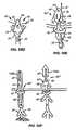
- FIG. 90various ways to connect elements to the braid of anchor 30 of replacement valve apparatus 10 are described.
- a post 32 having a single braid attachment hole 660is attached to anchor 30 along three separate intersections of the braid via suture S.
- Figure 90Bprovides a detail view of one exemplary technique for routing the suture between hole 660 and anchor 30.
- Figure 90Cillustrates a variation of the attachment, wherein post 32 comprises multiple braid attachment holes 660.
- elements other than posts 32may be attached to anchor 30 in the manner described, for example, anchor lock elements 34 may be attached in a similar manner.
- the distal region of anchor 30may be pulled proximally via a proximally directed force applied to posts 32 via a distal deployment system interface.
- the distal deployment system interfaceis adapted to expand radially during application of a proximally directed force on the distal end of the anchor.
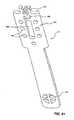
- fixture 200comprises approximately 6-20 posts, more preferably 8-18 posts, or more preferably 10-16 posts around its circumference, though any alternative number of posts may be provided.
- fixture 200preferably has a diameter of about 2-40mm, more preferably 4-30 mm, or more preferably 6-20mm, though any alternative diameter may be provided.
- the diameter of fixture 200preferably is the diameter of the braid in its "at rest" configuration.
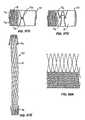
- Figure 92Aprovides a detail view of a proximal front side region of fixture 200 during formation of a braided anchor.
- Figure 92Bshows a detail backside view of a central section of the fixture.
- Figure 92Cshows a full-length frontside view of the fixture and
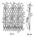
- Figure 92Dshows the completed braid, hi Figures 92 , anchor braid 30 is formed from a single strand of wrapped and interwoven wire W. However, it should be understood that anchor braid 30 alternatively may be formed from multiple strands of wire.
- the braidWhen anchor braid 30 is formed from a shape-memory material, the braid may be heat set such that it maintains a desired degree of expansion in an at-rest configuration.
- the heat set at-rest configurationmay comprise, for example, the delivery configuration (e.g., collapsed configuration) of Figure 50A , the deployed configuration (e.g., expanded configuration) of Figures 50B and 50C , or any desired configuration therebetween.
- the anchoris heat-set in a configuration between the delivery configuration and the deployed configuration.
- Anchor braid 30may be heat set while still disposed on fixture 200 to maintain an at-rest configuration as formed on the fixture, which preferably is a configuration between the delivery and deployed configurations.
- the braidmay be heat set after complete or partial removal from the fixture.
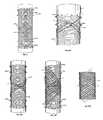
- FIGS 94A-Eadditional configurations for reducing sfress concentration and/or circumferential stiffness of anchor braid 30 are illustrated. Such configurations can be used independently or in conjunction with other configurations disclosed herein. Such configurations are preferably used at the anchor's edges to locally reduce the cross-sectional area of substantially all cells or all cells in the anchor braid's edge (e.g., proximal and/or distal). As seen in Figures 94A and 94B , turns Tu in wire W typically may have a substantially continuous (e.g., round) cross-sectional profile.
- Figure 97Eillustrates interlocking proximal and distal edge cell configurations while anchor 30 is disposed in the collapsed delivery configuration.
- the locking turn features of Figures 97may, for example, be formed by heat setting anchor braid 30 (or locking features only) in the desired configuration. Additional locking turn features will be apparent to those of skill in the art.
- the anchor locking mechanismcan be set to have alternative locking options that allow for various amounts of expansion.
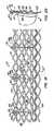
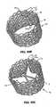
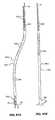
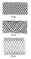
- Figure 99 Ais a side view representation of braided anchor of Figure 98D .
- the expanded anchoris illustrated having a denser weave (shorter pitch) at the distal and proximal ends; hence the dots are located closer to each other.
- the middle section of the anchoris composed of a looser weave that is generated by a higher pitch braid and is represented by dots that are farther away from each other.
- the braided anchoris foreshortened and the dots are collapsed closer to each other. In this case, the central portion of the anchor foreshortened more than the proximal and distal edges.
- the anchor and any of its featuresmay be heat set at different configurations.
- the anchormay be heat set ay its "at rest” configuration such that upon unsheathing it expands radially.
- the end turn features/leaflet engagement elementsmay be heat set at a different "at rest” configuration than the rest of the anchor.
- end turn featuresare heat set to "flower” and then "evert" upon unsheathing.
- Figures 32-34illustrate the process of forming a pleated seal around a replacement valve to prevent leakage.
- Figure 32illusfrates a fabric seal 380 prior to deployment and foreshortening of the anchor/valve apparatus.
- the fabric seal 380extends from the distal end of valve 20 proximally over anchor 30 during delivery.
- anchor 30foreshortens and the fabric seal 380 bunches up to create fabric flaps and pockets that extend into spaces formed by the native valve leaflets 382.
- the bunched up fabric or pleatsoccur, in particular, when the pockets are filled with blood in response to backflow blood pressure.
- the pleatingcan create a seal around the replacement valve.
- Figure 34illustrates anchor 30, surrounded by fabric seal 380 in between native valve leaflets 382. In preferred embodiments, at least a portion of a seal is captured between the leaflets and the wall of the heart when the anchor is fully deployed.
Landscapes
- Health & Medical Sciences (AREA)
- Cardiology (AREA)
- Engineering & Computer Science (AREA)
- Biomedical Technology (AREA)
- Life Sciences & Earth Sciences (AREA)
- Transplantation (AREA)
- Heart & Thoracic Surgery (AREA)
- Vascular Medicine (AREA)
- Oral & Maxillofacial Surgery (AREA)
- Animal Behavior & Ethology (AREA)
- General Health & Medical Sciences (AREA)
- Public Health (AREA)
- Veterinary Medicine (AREA)
- Prostheses (AREA)
- External Artificial Organs (AREA)
- Surgical Instruments (AREA)
Abstract
Description
- The present invention relates to methods and apparatus for endovascularly replacing a heart valve. More particularly, the present invention relates to methods and apparatus for percutaneously replacing a heart valve with a replacement valve using an expandable and retrievable anchor.
- Heart valve surgery is used to repair or replace diseased heart valves. Valve surgery is an open-heart procedure conducted under general anesthesia. An incision is made through the patient's sternum (sternotomy), and the patient's heart is stopped while blood flow is rerouted through a heart-lung bypass machine.
- Valve replacement may be indicated when there is a narrowing of the native heart valve, commonly referred to as stenosis, or when the native valve leaks or regurgitates.
When replacing the valve, the native valve is excised and replaced with either a biologic or a mechanical valve. Mechanical valves require lifelong anticoagulant medication to prevent blood clot formation, and clicking of the valve often may be heard through the chest. Biologic tissue valves typically do not require such medication. Tissue valves may be obtained from cadavers or may be porcine or bovine, and are commonly attached to synthetic rings that are secured to the patient's heart. - Valve replacement surgery is a highly invasive operation with significant concomitant risk. Risks include bleeding, infection, stroke, heart attack, arrhythmia, renal failure, adverse reactions to the anesthesia medications, as well as sudden death. 2-5% of patients die during surgery.
- Post-surgery, patients temporarily may be confused due to emboli and other factors associated with the heart-lung machine. The first 2-3 days following surgery are spent in an intensive care unit where heart functions can be closely monitored. The average hospital stay is between 1 to 2 weeks, with several more weeks to months required for complete recovery.
- In recent years, advancements in minimally invasive surgery and interventional cardiology have encouraged some investigators to pursue percutaneous replacement of the aortic heart valve. Percutaneous Valve Technologies ("PVT") of Fort Lee, New Jersey, has developed a balloon-expandable stent integrated with a bioprosthetic valve. The stent/valve device is deployed across the native diseased valve to permanently hold the valve open, thereby alleviating a need to excise the native valve and to position the bioprosthetic valve in place of the native valve. PVT's device is designed for delivery in a cardiac catheterization laboratory under local anesthesia using fluoroscopic guidance, thereby avoiding general anesthesia and open-heart surgery. The device was first implanted in a patient in April of 2002.
- PVT's device suffers from several drawbacks. Deployment of PVT's stent is not reversible, and the stent is not retrievable. This is a critical drawback because improper positioning too far up towards the aorta risks blocking the coronary ostia of the patient. Furthermore, a misplaced stent/valve in the other direction (away from the aorta, closer to the ventricle) will impinge on the mitral apparatus and eventually wear through the leaflet as the leaflet continuously rubs against the edge of the stent/valve.
- Another drawback of the PVT device is its relatively large cross-sectional delivery profile. The PVT system's stent/valve combination is mounted onto a delivery balloon, making retrograde delivery through the aorta challenging. An antegrade transseptal approach may therefore be needed, requiring puncture of the septum and routing through the mitral valve, which significantly increases complexity and risk of the procedure. Very few cardiologists are currently trained in performing a transseptal puncture, which is a challenging procedure by itself.
- Other prior art replacement heart valves use self-expanding stents as anchors. In the endovascular aortic valve replacement procedure, accurate placement of aortic valves relative to coronary ostia and the mitral valve is critical. Standard self-expanding systems have very poor accuracy in deployment, however. Often the proximal end of the stent is not released from the delivery system until accurate placement is verified by fluoroscopy, and the stent typically jumps once released. It is therefore often impossible to know where the ends of the stent will be with respect to the native valve, the coronary ostia and the mitral valve.
- Also, visualization of the way the new valve is functioning prior to final deployment is very desirable. Visualization prior to final and irreversible deployment cannot be done with standard self-expanding systems, however, and the replacement valve is often not fully functional before final deployment.
- Another drawback of prior art self-expanding replacement heart valve systems is their lack of radial strength. In order for self-expanding systems to be easily delivered through a delivery sheath, the metal needs to flex and bend inside the delivery catheter without being plastically deformed. In arterial stents, this is not a challenge, and there are many commercial arterial stent systems that apply adequate radial force against the vessel wall and yet can collapse to a small enough of a diameter to fit inside a delivery catheter without plastically deforming.
- However when the stent has a valve fastened inside it, as is the case in aortic valve replacement, the anchoring of the stent to vessel walls is significantly challenged during diastole. The force to hold back arterial pressure and prevent blood from going back inside the ventricle during diastole will be directly transferred to the stent/vessel wall interface. Therefore the amount of radial force required to keep the self expanding stent/valve in contact with the vessel wall and not sliding will be much higher than in stents that do not have valves inside of them. Moreover, a self-expanding stent without sufficient radial force will end up dilating and contracting with each heartbeat, thereby distorting the valve, affecting its function and possibly migrating and dislodging completely. Simply increasing strut thickness of the self-expanding stent is not a practical solution as it runs the risk of larger profile and/or plastic deformation of the self-expanding stent.
U.S. patent application Serial No. 2002/0151970 to Garrison et al. describes a two-piece device for replacement of the aortic valve that is adapted for delivery through a patient's aorta. A stent is percutaneously placed across the native valve, then a replacement valve is positioned within the lumen of the stent. By separating the stent and the valve during delivery, a profile of the device's delivery system may be sufficiently reduced to allow aortic delivery without requiring a transseptal approach. Both the stent and a frame of the replacement valve may be balloon-expandable or self-expanding.- While providing for an aortic approach, devices described in the Garrison patent application suffer from several drawbacks. First, the stent portion of the device is delivered across the native valve as a single piece in a single step, which precludes dynamic repositioning of the stent during delivery. Stent foreshortening or migration during expansion may lead to improper alignment.
- Additionally, Garrison's stent simply crushes the native valve leaflets against the heart wall and does not engage the leaflets in a manner that would provide positive registration of the device relative to the native position of the valve. This increases an immediate risk of blocking the coronary ostia, as well as a longer-term risk of migration of the device post-implantation. FurtherstiU, the stent comprises openings or gaps in which the replacement valve is seated post-delivery. Tissue may protrude through these gaps, thereby increasing a risk of improper seating of the valve within the stent.
WO 00/47139- The present invention is defined by an apparatus for replacing a native aortic valve as defined in
claim 1. The dependent claims depict advantageous features of the present invention. - Figures 1A-B
- are elevational views of a replacement heart valve and anchor according to one embodiment of the invention.
- Figures 2A-B
- are sectional views of the anchor and valve of
Figures 1 . - Figures 3A-B
- show delivery and deployment of a replacement heart valve and anchor, such as the anchor and valve of
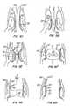
Figures 1 and 2 . - Figures 4A-F
- also show delivery and deployment of a replacement heart valve and anchor, such as the anchor and valve of
Figures 1 and 2 . - Figures 5A-I
- show the use of a replacement heart valve and anchor to replace an aortic valve.
- Figures 6A-F
- show the use of a replacement heart valve and anchor with a positive registration feature to replace an aortic valve.
- Figure 7
- shows the the use of a replacement heart valve and anchor with an alternative positive registration feature to replace an aortic valve.
- Figures 8A-C
- show another embodiment of a replacement heart valve and anchor.
- Figures 9A-H
- show delivery and deployment of the replacement heart valve and anchor of
Figures 8 . - Figure 10
- is a cross-sectional drawing of the delivery system used with the method and apparatus of
Figures 8 and9 . - Figures 11A-C
- show alternative locks for use with replacement heart valves and anchors.
- Figures 12A-C
- show a vessel wall engaging lock for use with replacement heart valves and anchors of this invention.
- Figure 13
- demonstrates paravalvular leaking around a replacement heart valve and anchor.
- Figure 14
- shows a seal for use with a replacement heart valve and anchor of this invention.
- Figures 15A-E
- show alternative arrangements of seals on a replacement heart valve and anchor.
- Figures 16A-C
- show alternative seal designs for use with replacement heart valves and anchors.
- Figures 17A-B
- show an alternative anchor lock embodiment in an unlocked configuration.
- Figures 18A-B
- show the anchor lock of
Figure 17 in a locked configuration. - Figure 19
- shows an alternative anchor deployment tool attachment and release mechanism for use with the invention.
- Figure 20
- shows the attachment and release mechanism of
Figure 19 in the process of being released. - Figure 21
- shows the attachment and release mechanism of
Figures 19 and 20 in a released condition. - Figure 22
- shows an alternative embodiment of a replacement heart valve and anchor and a deployment tool according to the invention in an undeployed configuration.
- Figure 23
- shows the replacement heart valve and anchor of
Figure 22 in a partially deployed configuration. - Figure 24
- shows the replacement heart valve and anchor of
Figures 22 and 23 in a more fully deployed configuration but with the deployment tool still attached. - Figure 25
- shows yet another embodiment of the delivery and deployment apparatus of the invention in use with a replacement heart valve and anchor.
- Figure 26
- shows the delivery and deployment apparatus of
Figure 25 in the process of deploying a replacement heart valve and anchor. - Figure 27
- shows an embodiment of the invention employing seals at the interface of the replacement heart valve and anchor and the patient's tissue.
- Figure 28
- is a longitudinal cross-sectional view of the seal shown in
Figure 27 in compressed form. - Figure 29
- is a transverse cross-sectional view of the seal shown in
Figure 28 . - Figure 30
- is a longitudinal cross-sectional view of the seal shown in
Figure 27 in expanded form. - Figure 31
- is a transverse cross-sectional view of the seal shown in
Figure 30 . - Figure 32
- shows yet another embodiment of the replacement heart valve and anchor of this invention in an undeployed configuration.
- Figure 33
- shows the replacement heart valve and anchor of
Figure 32 in a deployed configuration. - Figure 34
- shows the replacement heart valve and anchor of
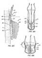
Figures 32 and 33 deployed in a patient's heart valve. - Figures 35A-H
- show yet another embodiment of a replacement heart valve, anchor and deployment system according to this invention.
- Figures 36A-E
- show more detail of the anchor of the embodiment shown in
Figures 35A-H . - Figures 37A-B
- show further details of the embodiment of
Figures 35A-H . - Figures 38 A-C
- illustrate a method for percutaneously replacing a patient's diseased heart valve.
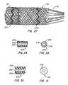
- Figures 39 A-B
- show an anchor for use in a two-piece replacement heart valve and anchor embodiment.
- Figures 40A-B
- show a replacement heart valve for use in a two-piece replacement heart valve and anchor embodiment.
- Figures 41A-D
- show a method of coupling the anchor of
Figures 39 and the replacement heart valve ofFigures 40 . - Figure 42
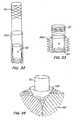
- shows a delivery system for use with the appartus shown in
Figures 39-41 .Figure 43 shows an alternative embodiment of a delivery system for use with the apparatus shown inFigures 39-41 . - Figure 44
- shows yet another alternative embodiment of a delivery system for use with the apparatus shown in
Figures 39-41 . - Figures 45A-I
- illustrate a method of deliverying and deploying a two-piece replacement heart valve and anchor.
- Figures 46A-B
- shows another embodiment of a two-piece replacement heart valve and anchor.
- Figure 47
- shows yet another embodiment of a two-piece replacement heart valve and anchor.
- Figure 48
- shows yet another embodiment of a two-piece replacement heart valve and anchor.
- Figures 49A and 49B
- show replacement valve apparatus in accordance with the present invention.
Figure 49 illustrates the apparatus in a collapsed delivery configuration within a delivery system.Figure 49B illustrates the apparatus in an expanded configuration partially deployed from the delivery system. - Figures 50A-50F
- show an anchor of the apparatus of
Figures 49 in the collapsed delivery configuration and the expanded deployed configuration, as well as the full apparatus in the deployed configuration, and optional locking mechanisms for use with the apparatus. - Figure 51
- shows a detail view of a variation of an anchor post.
- Figures 52A and 52B
- show an alternative variation of the post having a lock alignment feature.
- Figures 53A and 53B
- show a variation of the post having an alternative lock alignment feature.
- Figure 54
- shows a variation of the post having an expansile element.
- Figure 55
- shows a variation of the post with an alternative expansile or cable element.
- Figures 56A-56C
- show a variation of the post having an alternative lock alignment feature.
- Figure 57
- shows the post variation of
Figure 51 in combination with an illustrative actuator and release actuator. - Figures 58A-58C
- show a variation of the post, actuator and release actuator that form an alternative releasable attachment mechanism.
- Figures 59A-59C
- show another variation of the releasable attachment mechanism.
- Figures 60A-60C
- show yet another variation of the releasable attachment mechanism.
- Figures 61 A and 6 IB
- show still another variation of the releasable attachment element.
- Figure 62
- shows a variation of the post, actuator and anchor lock element having a reversible lock.
- Figures 63A-63C
- show a variation of the actuator, lock actuator and release actuator.
Figure 64 shows a variation of the anchor lock element having a lock alignment feature. - Figures 65 A and 65B
- show expansion, locking and actuation of the releasable attachment mechanism of the apparatus of
Figure 64 . - Figure 66
- shows another variation of the apparatus having an actuable lock prevention mechanism.
- Figures 67 A and 67B
- show a variation of the post that is configured to lock against the braid of the anchor.
- Figures 68A-68C
- show actuation and release of a variation of the anchor lock element.
- Figures 69A and 69B
- show another variation of a releasable actuation mechanism having a lock alignment mechanism which can be cut from a tube.
- Figures 70A-70D
- show actuation of a variation of the anchor lock element that may be formed from a cut tube.
- Figures 71A-71F
- show a variation of the post having an unlock actuator.
- Figures 72 A and 72B
- show another buckle variation of the anchor lock element.
- Figure 73
- shows attachment of a variation of the anchor lock element to the anchor.
- Figure 74
- shows a variation of the post and anchor lock element having a ratcheting lock.
- Figures 75A and 75B
- show variations of the ratcheting lock.
- Figures 76A-76H
- show actuation of another variation of the ratcheting lock.
- Figures 77A-77C
- show a tubular variation of the ratcheting lock element.
- Figures 78A-78C
- show a variation of the anchor lock element of
Figures 77 . - Figures 79 A and 79B
- show a variation of the apparatus of
Figures 78 comprising a lock alignment feature. - Figures 80A-80F
- show a method of actuating and adjusting the ratcheting lock of the apparatus of
Figures 78 . - Figures 81A and 81B
- show a variation of an anchor/actuator.
- Figures 82A-82C
- show detail views of the releasable attachment mechanism of the actuator of
Figures 81 . - Figures 83A-83C
- show a variation of the releasable attachment mechanism of
Figures 82 . - Figures 84A-84C
- show another variation of the releasable attachment mechanism.
- Figures 85A-85C
- show yet another variation of the releasable attachment mechanism.
Figures 86A-86N show variations of a release actuator used in conjunction with the releasable attachment mechanism ofFigures 82 . - Figures 87A and 87B
- show detail views of an embodiment of the delivery system/deployment tool.
- Figures 88A and 88B
- show the delivery system/deployment tool of
Figures 87 releaseably attached toapparatus 10, and detached from the apparatus. - Figures 89 A and 89B
- show a variation of the delivery system deployment tool of
Figures 87 and88 wherein the actuators extend from a unitary structure. - Figures 90A-90C
- show various ways to connect elements to the anchor of the replacement valve apparatus.
- Figure 91
- is a schematic top view of an apparatus for fabricating braided anchors.
- Figures 92A-92D
- are schematic top views illustrating a method of using the apparatus of
Figure 91 to fabricate a braided anchor. - Figures 93A-93O
- are schematic detail views illustrating features of braid cells at an anchor edge.
- Figures 94A-94E
- illustrate further features of braid cells at an anchor edge.
- Figures 95A-95J
- are schematic detail views terminations for one or more wire strands forming anchors.
- Figures 96 A and 96B
- are schematic side views of alternative embodiments of the anchor portion.
- Figures 97A-97E
- are schematic side views of further alternative embodiments of the of the anchor portion.
- Figures 98A-98D
- are schematic views of different weave configurations.
- Figures 99A-99E
- are schematic side views of various braided anchor configurations.
- Figures 100A-100E
- are schematic side views of a deployment process.
- Figures 101 A and 101B
- illustrate a braided anchor in the heart.
- Figures 102A and 102B
- illustrate a bilaterally symmetrical anchor and an asymmetric anchor, respectively.
- Figure 103
- illustrates a braided anchor of the present invention with closed end turns Tu.
- Figures 104A-104E
- illustrate additional features for end turns of a braided anchor.
- Figures 105A-105F
- illustrate deployment of an anchor with leaflet engagement elements on the deployment system.
- Figure 106
- illustrates a deployed anchor with leaflet engagement elements on the proximal end of the anchor.
- Figures 107A-107C
- illustrate deployment of an anchor with anchor registration elements and a seal.
- Figures 108A-108B
- illustrate an embodiment of the apparatus with a seal that does not reach the proximal end of the anchor during both systole and diastole.
- Figures 109A-109B
- illustrate an embodiment of the apparatus with a seal that reaches the proximal end of the anchor during both systole and diastole.
- The present invention relates to an apparatus for endovascularly or percutaneously delivering and deploying a prosthesis, e.g., an aortic prosthesis, within and/or across a patient's native heart valve, referred to hereinafter as replacing the patient's heart valve. A delivery system and/or deployment tool is provided including a sheath assembly and a guidewire for placing the prosthetic apparatus endovascularly within the patient and a user control allowing manipulation of the prosthetic apparatus from external to the patient through the application of a non-hydraulically expanding or non-pneumatically expanding force on the anchor. A hydraulically or pneumatically expanding force would be, for example, a force applied to the anchor by a balloon expanded within the anchor. In certain embodiments, the application of a non-hydraulically expanding or non-pneumatically expanding force could include the use of a hydraulic component transmitting a proximally or distally directed force on an anchor.
- The apparatus includes an anchor and a replacement valve. The anchor includes an expandable anchor such as a braid. In preferred embodiments, the expandable braid includes closed edges, but the edges may alternatively be open. The replacement valve is adapted to be secured within the anchor, and as such, be delivered endovascularly to the patient's heart to replace one of the patient's native heart valves. More preferably, the apparatus of the present invention contemplate replacement of the patient's aortic valve.
- With reference now to
Figures 1-4 , a first embodiment of replacement heart valve apparatus in accordance with the present invention is described, including a method of actively foreshortening and expanding the apparatus from a delivery configuration and to a deployed configuration.Apparatus 10 comprisesreplacement valve 20 disposed within and coupled toanchor 30.Figures 1 schematically illustrate individual cells ofanchor 30 ofapparatus 10, and should be viewed as if the cylindrical anchor has been cut open and laid flat.Figures 2 schematically illustrate a detail portion ofapparatus 10 in side-section. Anchor 30 has alip region 32, askirt region 35 and abody region 36. First, second andthird posts skirt region 35 and extend withinlumen 31 ofanchor 30.Posts 38 preferably are spaced 120° apart from one another about the circumference ofanchor 30.Anchor 30 preferably is fabricated by using self-expanding patterns (laser cut or chemically milled), braids, and materials, such as a stainless steel, nickel-titanium ("Nitinol") or cobalt chromium but alternatively may be fabricated using balloon-expandable patterns where the anchor is designed to plastically deform to it's final shape by means of balloon expansion.Replacement valve 20 is preferably from biologic tissues, e.g. porcine valve leaflets or bovine or equine pericardium tissues, alternatively it can be made from tissue engineered materials (such as extracellular matrix material from Small Intestinal Submucosa (SIS)) but alternatively may be prosthetic from an elastomeric polymer or silicone, Nitinol or stainless steel mesh or pattern (sputtered, chemically milled or laser cut). The leaflet may also be made of a composite of the elastomeric or silicone materials and metal alloys or other fibers such Kevlar or carbon.Annular base 22 ofreplacement valve 20 preferably is coupled toskirt region 35 ofanchor 30, whilecommissures 24 ofreplacement valve leaflets 26 are coupled to posts 38.Anchor 30 may be actuated using external non-hydraulic or non-pneumatic force to actively foreshorten in order to increase its radial strength. As shown below, the proximal and distal end regions ofanchor 30 may be actuated independently. The anchor and valve may be placed and expanded in order to visualize their location with respect to the native valve and other anatomical features and to visualize operation of the valve. The anchor and valve may thereafter be repositioned and even retrieved into the delivery sheath or catheter. The apparatus may be delivered to the vicinity of the patient's aortic valve in a retrograde approach in a catheter having a diameter no more than 23 french, preferably no more than 21 french, more preferably no more than 19 french, or more preferably no more than 17 french. Upon deployment the anchor and replacement valve capture the native valve leaflets and positively lock to maintain configuration and position.- A deployment tool is used to actuate, reposition, lock and/or retrieve
anchor 30. In order to avoid delivery ofanchor 30 on a balloon for balloon expansion, a non-hydraulic or non-pneumatic anchor actuator is used. In this embodiment, the actuator is a deployment tool that includes distalregion control actuators 50, control actuators 60 (embodied here as rods or tubes) and proximalregion control actuators 62.Locks 40 include posts orarms 38 preferably with male interlockingelements 44 extending fromskirt region 35 and matingfemale interlocking elements 42 inlip region 32. Male interlockingelements 44 haveeyelets 45.Control actuators 50 pass from a delivery system forapparatus 10 through female interlockingelements 42, througheyelets 45 of male interlockingelements 44, and back through female interlockingelements 42, such that a double strand ofwire 50 passes through each female interlockingelement 42 for manipulation by a medical practitioner external to the patient to actuate and control the anchor by changing the anchor's shape.Control actuators 50 may comprise, for example, strands of suture or wire. Actuators 60 are reversibly coupled toapparatus 10 and may be used in conjunction withactuators 50 to actuateanchor 30, e.g., to foreshorten and lockapparatus 10 in the fully deployed configuration.Actuators 60 also facilitate repositioning and retrieval ofapparatus 10, as described hereinafter. For example,anchor 30 may be foreshortened and radially expanded by applying a distally directed force onactuators 60 while proximally retractingactuators 50. As seen inFigures 3 ,control actuators 62 pass through interior lumens 61 ofactuators 60. This ensures thatactuators 60 are aligned properly withapparatus 10 during deployment and foreshortening.Control actuators 62 can also actuateanchor 60; proximally directed forces oncontrol actuators 62 contacts theproximal lip region 32 ofanchor 30.Actuators 62 also act to couple and decoupleactuators 60 fromapparatus 10.Actuators 62 may comprise, for example, strands of suture or wire.Figures 1 A and 2A illustrateanchor 30 in a delivery configuration or in a partially deployed configuration (e.g., after dynamic self-expansion expansion from a constrained delivery configuration within a delivery sheath).Anchor 30 has a relatively long length and a relatively small width in the delivery or partially deployed configuration, as compared to the foreshortened and fully deployed configuration of Figures IB and 2B.- In
Figures 1A and 2A ,replacement valve 20 is collapsed withinlumen 31 ofanchor 30. Retraction ofactuators 50 relative toactuators 60 foreshortens anchor 30, which increases the anchor's width while decreasing its length. Such foreshortening also properly seatsreplacement valve 20 withinlumen 31 ofanchor 30. Imposed foreshortening will enhance radial force applied byapparatus 10 to surrounding tissue over at least a portion ofanchor 30. In some embodiments, the anchor exerts an outward force on surrounding tissue to engage the tissue in such way to prevent migration of anchor caused by force of blood against closed leaflet during diastole. This anchoring force is preferably 454g-907g (1 to 2 lbs), more preferably 907g-1810g (2 to 4 lbs), or more preferably 1810g-4540g (4 to 10 lbs). In some embodiments, the anchoring force is preferably greater than 454g (1 pound) more preferably greater than 907g (2 pounds), or more preferably greater than 1810g (4 pounds). Enhanced radial force of the anchor is also important for enhanced crush resistance of the anchor against the surrounding tissue due to the healing response (fibrosis and contraction of annulus over a longer period of time) or to dynamic changes of pressure and flow at each heart beat In an alternative embodiment, the anchor pattern or braid is designed to have gaps or areas where the native tissue is allowed to protrude through the anchor slightly (not shown) and as the foreshortening is applied, the tissue is trapped in the anchor. This feature would provide additional means to prevent anchor migration and enhance long term stability of the device. - Deployment of
apparatus 10 is fully reversible untillock 40 has been locked via mating of male interlockingelements 44 with female interlockingelements 42. Deployment is then completed bydecoupling actuators 60 fromlip section 32 ofanchor 30 by retracting one end of each actuator 62 relative to the other end of the actuator, and by retracting one end of each actuator 50 relative to the other end of the actuator until each actuator has been removed fromeyelet 45 of its corresponding male interlockingelement 44. - As best seen in
Figure 2B ,body region 36 ofanchor 30 optionally may comprisebarb elements 37 that protrude fromanchor 30 in the fully deployed configuration, for example, for engagement of a patient's native valve leaflets and to preclude migration of the apparatus. - With reference now to
Figures 3 , a delivery and deployment system for a self-expanding embodiment ofapparatus 10 including asheath 110 having alumen 112. Self-expandinganchor 30 is collapsible to a delivery configuration withinlumen 112 ofsheath 110, such thatapparatus 10 may be delivered viadelivery system 100. As seen inFigure 3 A ,apparatus 10 may be deployed fromlumen 112 by retractingsheath 110 relative toapparatus 10,control actuators 50 andactuators 60, which causesanchor 30 to dynamically self-expand to a partially deployed configuration.Control actuators 50 then are retracted relative toapparatus 10 andactuators 60 to impose foreshortening uponanchor 30, as seen inFigure 3B . - During foreshortening, actuators 60 push against
lip region 32 ofanchor 30, while actuators 50 pull onposts 38 of the anchor.Actuators 62 may be retracted along withactuators 50 to enhance the distally-directed pushing force applied byactuators 60 tolip region 32. Continued retraction ofactuators 50 relative to actuators 60 would locklocks 40 and fully deployapparatus 10 withreplacement valve 20 properly seated withinanchor 30, as in Figures IB and 2B.Apparatus 10 comprises enhanced radial strength in the fully deployed configuration as compared to the partially deployed configuration ofFigure 3 A . Onceapparatus 10 has been fully deployed,actuators apparatus 10, thereby separatingdelivery system 100 includingactuators 60 from the apparatus. - Deployment of
apparatus 10 is fully reversible untillocks 40 have been actuated. For example, just prior to locking the position of the anchor and valve and the operation of the valve may be observed under fluoroscopy. If the position needs to be changed, by alternately relaxing and reapplying the proximally directed forces exerted bycontrol actuators 50 and/orcontrol actuators 62 and the distally directed forces exerted byactuators 60, expansion and contraction of the lip and skirt regions ofanchor 30 may be independently controlled so that the anchor and valve can be moved to, e.g., avoid blocking the coronary ostia or impinging on the mitral valve.Apparatus 10 may also be completely retrieved withinlumen 112 ofsheath 110 by simultaneously proximally retractingactuators 50 andactuators 60/actuators 62 relative tosheath 110.Apparatus 10 then may be removed from the patient or repositioned for subsequent redeployment. - Referring now to
Figures 4 , step-by-step deployment ofapparatus 10 viadelivery system 100 is described. InFigure 4A ,sheath 110 is retracted relative toapparatus 10,actuators 50 andactuators 60, thereby causing self-expandable anchor 30 to dynamically self-expandapparatus 10 from the collapsed delivery configuration withinlumen 112 ofsheath 110 to the partially deployed configuration.Apparatus 10 may then be dynamically repositioned viaactuators 60 to properly orient the apparatus, e.g. relative to a patient's native valve leaflets. - In
Figure 4B ,control actuators 50 are retracted whileactuators 60 are advanced, thereby urginglip region 32 ofanchor 30 in a distal direction while urgingposts 38 of the anchor in a proximal direction. This foreshortensapparatus 10, as seen inFigure 4C . Deployment ofapparatus 10 is fully reversible even after foreshortening has been initiated and has advanced to the point illustrated inFigure 4C . - In
Figure 4D , continued foreshortening causes male interlockingelements 44 oflocks 40 to engagefemale interlocking elements 42. The male elements mate with the female elements, thereby lockingapparatus 10 in the foreshortened configuration, as seen inFigure 4E .Actuators 50 are then pulled througheyelets 45 ofmale elements 44 to remove the actuators fromapparatus 10, andactuators 62 are pulled through the proximal end ofanchor 30 to uncoupleactuators 60 from the apparatus, thereby separatingdelivery system 100 fromapparatus 10. Fully deployedapparatus 10 is shown inFigure 4F . - Referring to
Figures 5 , a method not claimed by the invention of percutaneously replacing a patient's diseased aortic valve withapparatus 10 anddelivery system 100 is described. As seen inFigure 5 A ,sheath 110 ofdelivery system 100, havingapparatus 10 disposed therein, is percutaneously advanced over guide wire G, preferably in a retrograde fashion (although an antegrade or hybrid approach alternatively may be used), through a patient's aorta A to the patient's diseased aortic valve AV. Anosecone 102 precedessheath 110 in a known manner. InFigure 5B ,sheath 110 is positioned such that its distal region is disposed within left ventricle LV of the patient's heart H. Apparatus 10 is deployed fromlumen 112 ofsheath 110, for example, under fluoroscopic guidance, such thatanchor 30 ofapparatus 10 dynamically self-expands to a partially deployed configuration, as inFigure 5C . Advantageously,apparatus 10 may be retracted withinlumen 112 ofsheath 110 via actuators 50 - even afteranchor 30 has dynamically expanded to the partially deployed configuration, for example, to abort the procedure or to repositionapparatus 10 ordelivery system 100. As yet another advantage,apparatus 10 may be dynamically repositioned, e.g. viasheath 110 and/oractuators 60, in order to properly align the apparatus relative to anatomical landmarks, such as the patient's coronary ostia or the patient's native valve leaflets L. When properly aligned,skirt region 35 ofanchor 30 preferably is disposed distal of the leaflets, whilebody region 36 is disposed across the leaflets andlip region 32 is disposed proximal of the leaflets.- Once properly aligned,
actuators 50 are retracted relative toactuators 60 to impose foreshortening uponanchor 30 and expandapparatus 10 to the fully deployed configuration, as inFigure 5D . Foreshortening increases the radial strength ofanchor 30 to ensure prolonged patency of valve annulus An, as well as to provide a better seal forapparatus 10 that reduces paravalvular regurgitation. As seen inFigure 5E , locks 40 maintain imposed foreshortening.Replacement valve 20 is properly seated withinanchor 30, and normal blood flow between left ventricle LV and aorta A is thereafter regulated byapparatus 10. Deployment ofapparatus 10 advantageously is fully reversible untillocks 40 have been actuated. - As seen in
Figure 5F , actuators 50 have been pulled fromeyelets 45 ofmale elements 44 oflocks 40,actuators 60 are decoupled fromanchor 30, e.g. viaactuators 62, anddelivery system 100 is removed from the patient, thereby completing deployment ofapparatus 10.Optional barb elements 37 engage the patient's native valve leaflets, e.g. to further preclude migration of the apparatus and/or reduce paravalvular regurgitation. Figures 5G and5H show further details of deployment using a deployment apparatus.Apparatus 10 is deployed from lumen Lu ofsheath 110, for example, under fluoroscopic guidance by proximally retractingproximal handle 111 ofsheath 110 relative toshaft 108, such thatanchor 30 ofapparatus 10 dynamically self-expands to the partially deployed configuration ofFigure 5C . Advantageously,apparatus 10 may be retracted within lumen Lu ofsheath 110 by retractingshaft 108 relative to the sheath, and thereby retractingactuators 106a coupled to anchor 30 relative tosheath 110. In this manner,anchor 30 may be retrieved even after the anchor has dynamically expanded to the partially deployed configuration, for example, to abort the procedure or to repositionapparatus 10 ordelivery system 100. As yet another advantage,apparatus 10 may be dynamically repositioned, in order to properly align the apparatus relative to anatomical landmarks, such as the patient's coronary ostia or the patient's native valve leaflets L. When properly aligned, a distal region ofanchor 30 preferably is disposed distal of the leaflets, while a central region of the anchor is disposed across the leaflets and a proximal region is disposed proximal of the leaflets.- Once properly aligned,
actuators 106b are proximally retracted relative to actuators 106a, e.g., viaknob 126 ofhandle 120, to impose foreshortening uponanchor 30 and further expandapparatus 10 to the fully deployed configuration, as inFigure 5D . Foreshortening increases the radial strength ofanchor 30 to ensure prolonged patency of valve annulus An, as well as to provide a better seal forapparatus 10 that reduces paravalvular regurgitation.Lock 40 formed by engagingpost lock elements 44 ofposts 32 withanchor lock elements 34 ofanchor 30 maintains imposed foreshortening.Replacement valve 20 is properly seated withinanchor 30, and normal blood flow between left ventricle LV and aorta A is thereafter completely regulated byapparatus 10, althoughvalve 20 is functional during deployment as well. Deployment ofapparatus 10 advantageously is fully reversible until the locks have been actuated. Releasable lock prevention mechanisms may be provided to ensure that the locks are not actuated prematurely. Furthermore, the locks may be reversible, such thatapparatus 10 may be retrieved or repositioned even after actuation of the locks. - Once
apparatus 10 is fully expanded and locked in the expanded configuration,actuators 106a are decoupled fromanchor 30 by actuating releasable attachment mechanisms, e.g., by retractingrelease actuators 112 relative to theactuators 106a viaknob 122 ofhandle 120. Likewise,actuators 106b are decoupled fromposts 32 by actuating releasable attachment mechanisms, e.g., by retractingrelease actuators 112 relative to theactuators 106b viaknob 124 ofhandle 120. As seen inFigure 5E ,delivery system 100 then may be removed from the patient, thereby completing deployment ofapparatus 10.Optional barb elements 37 engage the patient's native valve leaflets, e.g. to preclude migration of the apparatus and/or to reduce paravalvular regurgitation. - With reference now to
Figures 6 , a method not claimed by the invention of percutaneously replacing a patient's diseased aortic valve withapparatus 10 is provided, wherein proper positioning of the apparatus is ensured via positive registration of a modified delivery system to the patient's native valve leaflets. InFigure 6A , modified delivery system 100' deliversapparatus 10 to diseased aortic valve AV withinsheath 110. As seen inFigures 6B and 6C ,apparatus 10 is deployed fromlumen 112 ofsheath 110, for example, under fluoroscopic guidance, such thatanchor 30 ofapparatus 10 dynamically self-expands to a partially deployed configuration. As when deployed viadelivery system 100, deployment ofapparatus 10 via delivery system 100' is fully reversible untillocks 40 have been actuated. - Delivery system 100' comprises
leaflet engagement element 120, which preferably self-expands along withanchor 30.Engagement element 120 is disposed betweenactuators 60 of delivery system 100' andlip region 32 ofanchor 30.Element 120 releasably engages the anchor. As seen inFigure 6C , the element is initially deployed proximal of the patient's native valveleaflets L. Apparatus 10arid element 120 then may be advanced/dynamically repositioned until engagement element positively registers against the leaflets, thereby ensuring proper positioning ofapparatus 10. Also delivery system 100' includesfilter structure 61 A (e.g., filter membrane or braid) as part ofpush actuators 60 to act as an embolic protection element. Emboli can be generated during manipulation and placement of anchor from either diseased native leaflet or surrounding aortic tissue and can cause blockage.Arrows 6 IB inFigure 6E show blood flow throughfilter structure 61 A where blood is allowed to flow but emboli is trapped in the delivery system and removed with it at the end of the procedure. - Alternatively, foreshortening may be imposed upon
anchor 30 whileelement 120 is disposed proximal of the leaflets, as inFigure 6D . Upon positive registration ofelement 120 against leaflets L,element 120 precludes further distal migration ofapparatus 10 during additional foreshortening, thereby reducing a risk of improperly positioning the apparatus.Figure 6E details engagement ofelement 120 against the native leaflets. As seen inFigure 6F , onceapparatus 10 is fully deployed,element 120,actuators 50 andactuators 60 are decoupled from the apparatus, and delivery system 100' is removed from the patient, thereby completing the procedure. - With reference to
Figure 7 , an alternative embodiment of the apparatus ofFigures 6 is described, whereinleaflet engagement element 120 is coupled to anchor 30 ofapparatus 10', rather than todelivery system 100.Engagement element 120 remains implanted in the patient post-deployment ofapparatus 10'. Leaflets L are sandwiched betweenlip region 32 ofanchor 30 andelement 120 in the fully deployed configuration. In this manner,element 120 positively registersapparatus 10' relative to the leaflets and precludes distal migration of the apparatus over time. - Referring now to
Figures 8 , an alternative delivery system adapted for use with a balloon expandable embodiment of the present invention is described. InFigure 8 A ,apparatus 10" comprises anchor 30' that maybe fabricated from balloon-expandable materials.Delivery system 100" comprisesinflatable member 130 disposed in a deflated configuration withinlumen 31 of anchor 30'. InFigure 8B , optionalouter sheath 110 is retracted, andinflatable member 130 is inflated to expand anchor 30' to the fully deployed configuration. Asinflatable member 130 is being deflated, as in earlier embodiments,actuators actuators 60 maybe used to assist deployment of anchor 30' and actuation oflocks 40, as well as to provide reversibility and retrievability ofapparatus 10" prior to actuation oflocks 40. Next,actuators actuators 60 are removed fromapparatus 10", anddelivery system 100" is removed, as seen inFigure 8C . - As an alternative delivery method not claimed by the invention, anchor 30' may be partially deployed via partial expansion of
inflatable member 130. The inflatable member would then be advanced withinreplacement valve 20 prior to inflation ofinflatable member 130 and full deployment ofapparatus 10". Inflation pressures used will range from about 3 to 6 arm, or more preferably from about 4 to 5 arm, though higher and lower atm pressures may also be used (e.g., greater than 3 atm, more preferably greater than 4 atm, more preferably greater than 5 atm, or more preferably greater than 6 atm). Advantageously, separation ofinflatable member 130 fromreplacement valve 20, until partial deployment ofapparatus 10" at a treatment site, is expected to reduce a delivery profile of the apparatus, as compared to previously known apparatus. This profile reduction may facilitate retrograde delivery and deployment ofapparatus 10", even when anchor 30' is balloon-expandable. - Although anchor 30' has illustratively been described as fabricated from balloon-expandable materials, it should be understood that anchor 30' alternatively may be fabricated from self-expanding materials whose expansion optionally may be balloon-assisted. In such a configuration, anchor 30' would expand to a partially deployed configuration upon removal of
outer sheath 110. If required,inflatable member 130 then would be advanced withinreplacement valve 20 prior to inflation.Inflatable member 130 would assist full deployment ofapparatus 10", for example, when the radial force required to overcome resistance from impinging tissue were too great to be overcome simply by manipulation ofactuators 50 andactuators 60. Advantageously, optional placement ofinflatable member 130 withinreplacement valve 20, only after dynamic self-expansion ofapparatus 10" to the partially deployed configuration at a treatment site, is expected to reduce a delivery profile of the apparatus, as compared to previously known apparatus. This reduction may facilitate retrograde delivery and deployment ofapparatus 10". - With reference to
Figures 9 and10 , methods and apparatus for a balloon-assisted embodiment are described in greater detail.Figures 9 and10 illustratively showapparatus 10' ofFigures 7 used in combination withdelivery system 100" ofFigures 8 .Figure 10 illustrates a sectional view ofdelivery system 100".Inner shaft 132 ofinflatable member 130 preferably is about 4 Fr in diameter, and compriseslumen 133 configured for passage of guidewire G, having a diameter of about 0.035", therethrough.Push actuators 60 and pullactuators 50 pass throughguidetube 140, which preferably has a diameter of about 15 Fr or smaller.Guide tube 140 is disposed withinlumen 112 ofouter sheath 110, which preferably has a diameter of about 17 Fr or smaller. - In
Figure 9A ,apparatus 10' is delivered to diseased aortic valve AV withinlumen 112 ofsheath 110. InFigure 9B ,sheath 110 is retracted relative toapparatus 10' to dynamically self-expand the apparatus to the partially deployed configuration. Also retracted and removed isnosecone 102 which is attached to a pre-slit lumen (not shown) that facilitates its removal prior to loading and advancing of a regular angioplasty balloon catheter over guidewire and insidedelivery system 110. - In
Figure 9C , pullactuators 50 and pushactuators 60 are manipulated from external to the patient to foreshortenanchor 30 and sufficiently expandlumen 31 of the anchor to facilitate advancement ofinflatable member 130 withinreplacement valve 20. Also shown is the tip of anangioplasty catheter 130 being advanced throughdelivery system 110. - The angioplasty balloon catheter or
inflatable member 130 then is advanced within the replacement valve, as inFigure 9D , and additional foreshortening is imposed uponanchor 30 to actuatelocks 40, as inFigure 9E . The inflatable member is inflated to further displace the patient's native valve leaflets L and ensure adequate blood flow through, and long-term patency of,replacement valve 20, as inFigure 9F .Inflatable member 130 then is deflated and removed from the patient, as inFigure 9G . A different size angioplasty balloon catheter could be used repeat the same step if deemed necessary by the user. Push actuators 60 optionally may be used to further setleaflet engagement element 120, or optional barbs B along posts 38, more deeply within leaflets L, as inFigure 9H . Then,delivery system 100" is removed from the patient, thereby completing percutaneous heart valve replacement. - As will be apparent to those of skill in the art, the order of imposed foreshortening and balloon expansion described in
Figures 9 and10 is only provided for the sake of illustration. The actual order may vary according to the needs of a given patient and/or the preferences of a given medical practitioner. Furthermore, balloon-assist may not be required in all instances, and the inflatable member may act merely as a safety precaution employed selectively in challenging clinical cases. - Referring now to
Figures 11 , alternative locks for use with apparatus of the present invention are described. InFigure 11 A ,lock 40' comprises male interlockingelement 44 as described previously. However, female interlocking element 42' illustratively comprises a triangular shape, as compared to the round shape of interlockingelement 42 described previously. The triangular shape of female interlocking element 42' may facilitate mating of male interlockingelement 44 with the female interlocking element without necessitating deformation of the male interlocking element. - In
Figure 11 B , lock 40" comprises alternative male interlocking element 44' having multiple in-line arrowheads 46 along posts 38. Each arrowhead comprises resilientlydeformable appendages 48 to facilitate passage through female interlockingelement 42.Appendages 48 optionally compriseeyelets 49, such that control actuator 50 or a secondary wire may pass therethrough to constrain the appendages in the deformed configuration. To actuatelock 40", one ormore arrowheads 46 of male interlocking element 44' are drawn through female interlockingelement 42, and the wire is removed fromeyelets 49, thereby causingappendages 48 to resiliently expand and actuatelock 40". - Advantageously, providing
multiple arrowheads 46 alongposts 38 yields a ratchet that facilitates in-vivo determination of a degree of foreshortening imposed upon the apparatus. Furthermore, optionally constrainingappendages 48 ofarrowheads 46 viaeyelets 49 prevents actuation oflock 40" (and thus deployment of apparatus) even after male element 44' has been advanced throughfemale element 42. Only after a medical practitioner has removed thewire constraining appendages 48 islock 40" fully engaged and deployment no longer reversible. Lock 40"' ofFigure 11 C is similar to lock 40" ofFigure 11B , except thatoptional eyelets 49 onappendages 48 have been replaced byoptional overtube 47.Overtube 47 serves a similar function toeyelets 49 by constrainingappendages 48 to prevent locking until a medical practitioner has determined that apparatus of the present invention has been foreshortened and positioned adequately at a treatment site.Overtube 47 is then removed, which causes the appendages to resiliently expand, thereby fully actuatinglock 40"'.- With reference to
Figures 12 , an alternative locking mechanism is described that is configured to engage the patient's aorta. Male interlockingelements 44" oflocks 40"" comprise arrowheads 46' having sharpened appendages 48'. Upon expansion from the delivery configuration ofFigure 12A to the foreshortened configuration ofFigure 12B ,apparatus 10 positions sharpened appendages 48' adjacent the patient's aorta A. Appendages 48' engage the aortic wall and reduce a risk of device migration over time. - With reference now to
Figure 13 , a risk of paravalvular leakage or regurgitation around an apparatus is described. InFigure 13 ,apparatus 10 has been implanted at the site of diseased aortic valve AV, for example, using techniques described hereinabove. The surface of native valve leaflets L is irregular, and interface I between leaflets L andanchor 30 may comprise gaps where blood B may seep through. Such leakage poses a risk of blood clot formation or insufficient blood flow. - Referring to
Figure 14 , optional elements for reducing regurgitation or leakage are described.Compliant sacs 200 may be disposed about the exterior ofanchor 30 to provide a more efficient seal along irregularinterface I. Sacs 200 may be filled with an appropriate material, for example, water, blood, foam or a hydrogel. Alternative fill materials will be apparent. - With reference to
Figures 15 , illustrative arrangements forsacs 200 are provided. InFigure 15 A ,sacs 200 are provided as discrete sacs at different positions along the height ofanchor 30. InFigure 15B , the sacs are provided as continuous cylinders at various heights. InFigure 15C , a single sac is provided with a cylindrical shape that spans multiple heights. The sacs ofFigure 15D are discrete, smaller and provided in larger quantities.Figure 15E provides a spiral sac. Alternative sac configurations will be apparent to those of skill in the art. - With reference to
Figures 16 , exemplary techniques for fabricatingsacs 200 are provided. InFigure 16A ,sacs 20 comprise 'fish-scale'slots 202 that may be back-filled, for example, with ambient blood passing throughreplacement valve 20. hiFigure 16B , the sacs comprisepores 204 that may be used to fill the sacs. InFigure 16C , the sacs open to lumen 31 ofanchor 30 and are filled by blood washing past the sacs as the blood moves throughapparatus 10. Figures 17 and 18 show yet another alternative embodiment of the anchor lock.Anchor 300 has a plurality of male interlockingelements 302 havingeyelets 304 formed therein. Male interlocking elements are connected tobraided structure 300 by inter-weaving elements 302 (and 308) or alternatively suturing, soldering, welding, or connecting with adhesive.Valve commissures 24 are connected to male interlockingelements 302 along their length.Replacement valve 20annular base 22 is connected to thedistal end 34 of anchor 300 (or 30) as is illustrated infigures 1A and IB. Male interlockingelements 302 also includeholes 306 that mate withtabs 310 extending intoholes 312 infemale interlocking elements 308. To lock,control actuators 314 passing througheyelets 304 andholes 312 are pulled proximally with respect to the proximal end ofbraided anchor 300 to draw the male interlocking elements throughholes 312 so thattabs 310 engageholes 306 in male interlockingelements 302. Also shown isrelease actuators 314B that passes througheylet 304B infemale interlocking element 308. If needed, during the procedure, the user may pull onrelease actuators 314B reversing orientation oftabs 310 releasing the anchor and allowing for repositioning of the device or it's removal from the patient. After the desired final position has been attained,release actuator 314B andcontrol actuator 314 be removed from the patient with the delivery system.Figures 19-21 show an alternative way of releasing the connection between the anchor and its actuating actuators and control actuators. Control actuators 62 (i.e., release actuators) extend throughactuators 60 from outside the patient, loop through the proximal region ofanchor 30 and extend partially back into tube 60 (i.e., an anchor actuator). The doubled up portion ofcontrol actuator 62 creates a force fit withintube 60 that maintains the control actuators's position with respect totube 60 when all confrol actuators 62 are pulled proximally to place a proximally directed force onanchor 30. When a single half ofcontrol actuator 62 is pulled proximally, however, the frictional fit between that control wire and the tube in which it is disposed is overcome, enabling theend 63 ofcontrol actuator 62 to pull free of the tube, as shown inFigure 21 , thereby releasinganchor 30.Figures 22-24 show an alternative embodiment of the anchor.Anchor 350 is made of a metal braid, such as Nitinol or stainless steel. Areplacement valve 354 is disposed withinanchor 350.Anchor 350 is actuated in substantially the same way asanchor 30 ofFigures 1-4 through the application of proximally and distally directed forces from confrol actuators (not shown) andactuators 352.Figures 25 and 26 show yet another embodiment of the delivery and deployment apparatus. As an alternative to the balloon expansion method described with respect toFigures 8 , in this embodiment the nosecone (e.g.,element 102 ofFigures 5 ) is replaced by anangioplasty balloon catheter 360. Thus,expandable balloon cathether 360 precedessheath 110 on guidewire G. Whenanchor 30 andvalve 20 are expanded through the operation ofactuators 60 and the control actuators (not shown) as described above,balloon cathether 360 is retracted proximally within the expanded anchor and valve and expanded further as described above with respect toFigures 8 .Figures 27-31 show seals 370 that expand over time to seal the interface between the anchor and valve and the patient's tissue.Seals 370 are preferably formed from Nitinol wire surrounded by an expandable foam. As shown in cross-section inFigures 28 and 29 , at the time of deployment, thefoam 372 is compressed about thewire 374 and held in the compressed form by a time-releasedcoating 376. After deployment,coating 376 dissolves in vivo to allowfoam 372 to expand, as shown inFigures 30 and 31 .Figures 32-34 show another way to seal the replacement valve against leakage. Afabric seal 380 extends from the distal end ofvalve 20 and back proximally overanchor 30 during delivery. When deployed, as shown inFigures 33 and 34 ,fabric seal 380 bunches up to create fabric flaps and pockets that extend into spaces formed by thenative valve leaflets 382, particularly when the pockets are filled with blood in response to backflow blood pressure. This arrangement creates a seal around the replacement valve.Figures 35A-H show another embodiment of a replacement heart valve apparatus.Apparatus 450 comprises replacement valve 460 (seeFigures 37B and38C ) disposed within and coupled toanchor 470.Replacement valve 460 is preferably biologic, e.g. porcine, but alternatively may be synthetic.Anchor 470 preferably is fabricated from self-expanding materials, such as a stainless steel wire mesh or a nickel-titanium alloy ("Nitinol"), and compriseslip region 472,skirt region 474, andbody regions Replacement valve 460 preferably is coupled toskirt region 474, but alternatively may be coupled to other regions of the anchor. As described herein below,lip region 472 andskirt region 474 are configured to expand and engage/capture a patient's native valve leaflets, thereby providing positive registration, reducing paravalvular regurgitation, reducing device migration, etc.- As seen in
Figure 35A ,apparatus 450 is collapsible to a delivery configuration, wherein the apparatus may be delivered viadelivery system 410.Delivery system 410 comprisessheath 420 havinglumen 422, as well as actuators 424a and 424b seen inFigures 35D-35G . Actuators 424a are configured to expandskirt region 474 ofanchor 470, as well asreplacement valve 460 coupled thereto, whileactuators 424b are configured to expandlip region 472. - As seen in
Figure 35B ,apparatus 450 may be delivered and deployed fromlumen 422 ofcatheter 420 while the apparatus is disposed in the collapsed delivery configuration. As seen inFigures 35B-35D ,catheter 420 is retracted relative toapparatus 450, which causesanchor 470 to dynamically self-expand to a partially deployed configuration. Actuators 424a are then retracted to expandskirt region 474, as seen inFigures 35E and 35F . Preferably, such expansion may be maintained via locking features described hereinafter. - In
Figure 35G ,actuators 424b are retracted to expandlip region 472 and fully deployapparatus 450. As withskirt region 474, expansion oflip region 472 preferably may be maintained via locking features. After bothlip region 472 andskirt region 474 have been expanded, actuators 424 may be removed fromapparatus 450, thereby separatingdelivery system 410 from the apparatus.Delivery system 410 then may be removed, as seen inFigure 35H . - As will be apparent to those of skill in the art,
lip region 472 optionally may be expanded prior to expansion ofskirt region 474. As yet another alternative,lip region 472 andskirt region 474 optionally may be expanded simultaneously, in parallel, in a step-wise fashion or sequentially. Advantageously, delivery ofapparatus 450 is fully reversible untillip region 472 orskirt region 474 has been locked in the expanded configuration. - With reference now to
Figures 36A-E , individual cells ofanchor 470 ofapparatus 450 are described to detail deployment and expansion of the apparatus. InFigure 36A , individual cells oflip region 472,skirt region 474 andbody regions lumen 422 ofsheath 420 ofdelivery system 410 ofFigures 35 . A portion of the cells formingbody regions 476, for example, every 'nth' row of cells, comprises locking features. Body region 476a comprises male interlockingelement 482 oflip lock 480, whilebody region 476b comprisesfemale interlocking element 484 oflip lock 480.Male element 482 compriseseyelet 483.Wire 424b passes fromfemale interlocking element 484 througheyelet 483 and back throughfemale interlocking element 484, such that there is a double strand ofwire 424b that passes throughlumen 422 ofcatheter 420 for manipulation by a medical practitioner external to the patient.Body region 476b further comprises male interlockingelement 492 ofskirt lock 490, whilebody region 476c comprisesfemale interlocking element 494 of the skirt lock. Wire 424a passes fromfemale interlocking element 494 througheyelet 493 ofmale interlocking element 492, and back throughfemale interlocking element 494.Lip lock 480 is configured to maintain expansion oflip region 472, whileskirt lock 490 is configured to maintain expansion ofskirt region 474.- In
Figure 36B ,anchor 470 is shown in the partially deployed configuration, e.g., after deployment fromlumen 422 ofsheath 420.Body regions 476, as well aslip region 472 andskirt region 474, self-expand to the partially deployed configuration. Full deployment is then achieved by refracting actuators 424 relative to anchor 470, and expandinglip region 472 andskirt region 474 outward, as seen inFigures 36C and 36D . As seen inFigure 36E , expansion continues until the male elements engage the female interlocking elements oflip lock 480 andskirt lock 490, thereby maintaining such expansion (lip lock 480 shown inFigure 36E ). Advantageously, deployment ofapparatus 450 is fully reversible untillip lock 480 and/orskirt lock 490 has been actuated. - With reference to
Figures 37A-B , isometric views, partially in section, further illustrateapparatus 450 in the fully deployed and expanded configuration.Figure 37A illustrates the wireframe structure ofanchor 470, whileFigure 37B illustrates an embodiment ofanchor 470 covered in a biocompatible material B. Placement ofreplacement valve 460 withinapparatus 450 may be seen inFigure 37B . The patient's native valve is captured betweenlip region 472 andskirt region 474 ofanchor 470 in the fully deployed configuration (seeFigure 38B ). - Referring to
Figures 38 A-C , in conjunction withFigures 35 and36 , a method not claimed by the current invention for percutaneously replacing a patient's diseased aortic valve withapparatus 450 is described.Delivery system 410, havingapparatus 450 disposed therein, is percutaneously advanced, preferably in a retrograde fashion, through a patient's aorta A to the patient's diseased aortic valve AV.Sheath 420 is positioned such that its distal end is disposed within left ventricle LV of the patient's heart H. As described with respect toFigures 35 ,apparatus 450 is deployed fromlumen 422 ofsheath 420, for example, under fluoroscopic guidance, such thatskirt section 474 is disposed within left ventricle LV,body section 476b is disposed across the patient's native valve leaflets L, andlip section 472 is disposed within the patient's aorta A. Advantageously,apparatus 450 may be dynamically repositioned to obtain proper alignment with the anatomical landmarks. Furthermore,apparatus 450 may be refracted withinlumen 422 ofsheath 420 via actuators 424, even afteranchor 470 has dynamically expanded to the partially deployed configuration, for example, to abort the procedure or to repositionsheath 420. - Once properly positioned, elements 424a are retracted to expand
skirt region 474 ofanchor 470 within left ventricle LV.Skirt region 474 is locked in the expanded configuration viaskirt lock 490, as previously described with respect toFigures 36 . InFigure 38 A ,skirt region 474 is maneuvered such that it engages the patient's valve annulus An and/or native valve leaflets L, thereby providing positive registration ofapparatus 450 relative to the anatomical landmarks. Elements 424b are then actuated external to the patient in order to expandlip region 472, as previously described inFigures 35 .Lip region 472 is locked in the expanded configuration vialip lock 480. Advantageously, deployment ofapparatus 450 is fully reversible untillip lock 480 and/orskirt lock 490 has been actuated. Elements 424 are pulled fromeyelets delivery system 410 is removed from the patient. As will be apparent, the order of expansion oflip region 472 andskirt region 474 may be reversed, concurrent, etc.- As seen in
Figure 38B ,lip region 472 engages the patient's native valve leaflets L, thereby providing additional positive registration and reducing a risk oflip region 472 blocking the patient's coronary ostia O.Figure 38C illustrates the same in cross-sectional view, while also showing the position ofreplacement valve 460. The patient's native leaflets are engaged and/or captured betweenlip region 472 andskirt region 474. Advantageously,lip region 472 precludes distal migration ofapparatus 450, whileskirt region 474 precludes proximal migration. It is expected thatlip region 472 andskirt region 474 also will reduce paravalvular regurgitation. - With reference to
Figures 39-41 , a first embodiment of two-piece apparatus of the present invention adapted for percutaneous replacement of a patient's heart valve is described. As seen inFigures 41 ,apparatus 510 comprises a two-piece device having custom-designedexpandable anchor piece 550 ofFigures 39 and expandablereplacement valve piece 600 ofFigures 40 . Bothanchor piece 550 andvalve piece 600 have reduced delivery configurations and expanded deployed configurations. Both may be either balloon expandable (e.g. fabricated from a stainless steel) or self-expanding (e.g. fabricated from a nickel-titanium alloy ("Nitinol") or from a wire mesh) from the delivery to the deployed configurations. - When replacing a patient's aortic valve,
apparatus 510 preferably may be delivered through the patient's aorta without requiring a transseptal approach, thereby reducing patient trauma, complications and recovery time. Furthermore,apparatus 510 enables dynamic repositioning ofanchor piece 550 during delivery and facilitates positive registration ofapparatus 510 relative to the native position of the patient's valve, thereby reducing a risk of device migration and reducing a risk of blocking or impeding flow to the patient's coronary ostia. Furthermore, the expanded deployed configuration ofapparatus 510, as seen inFigure 41D , is adapted to reduce paravalvular regurgitation, as well as to facilitate proper seating ofvalve piece 600 withinanchor piece 550. - As seen in
Figures 39 ,anchor piece 550 preferably comprises three sections.Lip section 560 is adapted to engage the patient's native valve leaflets to provide positive registration and ensure accurate placement of the anchor relative to the patient's valve annulus during deployment, while allowing for dynamic repositioning of the anchor during deployment.Lip section 560 also maintains proper positioning of composite anchor/valve apparatus 510 post-deployment to preclude distal migration.Lip section 560 optionally may be covered or coated with biocompatible film B (seeFigures 41 ) to ensure engagement of the native valve leaflets. It is expected that coveringlip section 560 with film B especially would be indicated when the native leaflets are stenosed and/or fused together Groove section 570 ofanchor piece 550 is adapted to engage an expandable frame portion, described hereinbelow, ofvalve piece 600 to coupleanchor piece 550 tovalve piece 600. As compared to previously known apparatus,groove section 570 comprises additional material and reduced openings or gaps G, which is expected to reduce tissue protrusion through the gaps upon deployment, thereby facilitating proper seating of the valve within the anchor.Groove section 570 optionally may be covered or coated with biocompatible film B (seeFigures 41 ) to further reduce native valve tissue protrusion through gaps G.- Finally,
skirt section 580 ofanchor piece 550 maintains proper positioning of composite anchor/valve apparatus 510 post-deployment by precluding proximal migration. When replacing a patient's aortic valve,skirt section 580 is deployed within the patient's left ventricle. As withlip section 560 andgroove section 570,skirt section 580 optionally may be covered or coated with biocompatible film B (seeFigures 41 ) to reduce paravalvular regurgitation. As will be apparent to those of skill in the art, all, a portion of, or none ofanchor piece 50 may be covered or coated with biocompatible film B. - In
Figure 39A , a portion ofanchor piece 550 has been flattened out to illustrate the basic anchor cell structure, as well as to illustrate techniques formanufacturing anchor piece 550. hi order to form the entire anchor,anchor 550 would be bent at the locations indicated inFigure 39 A , and the basic anchor cell structure would be revolved to form a joined 360° structure.Lip section 560 would be bent back into the page to form a lip that doubles over the groove section,groove section 570 would be bent out of the page into a 'C- or 'U'-shaped groove, whileskirt section 580 would be bent back into the page.Figure 39B shows the anchor portion after bending and in an expanded deployed configuration. - The basic anchor cell structure seen in
Figure 39A is preferably formed through laser cutting of a flat sheet or of a hollow tube placed on a mandrel. When formed from a flat sheet, the sheet would be cut to the required number of anchor cells, bent to the proper shape, and revolved to form a cylinder. The ends of the cylinder would then be joined together, for example, by welding. - If balloon expandable,
anchor piece 550 would be formed from an appropriate material, such as stainless steel, and then crimped onto a balloon delivery catheter in a collapsed delivery configuration. If self-expanding and formed from a shape-memory material, such as a nickel-titanium alloy ("Nitinol"), the anchor piece would be heat-set such that it could be constrained within a sheath in the collapsed delivery configuration, and then would dynamically self-expand to the expanded deployed configuration upon removal of the sheath. Likewise, ifanchor piece 550 were formed from a wire mesh or braid, such as a spring steel braid, the anchor would be constrained within a sheath in the delivery configuration and dynamically expanded to the deployed configuration upon removal of the sheath. - In
Figures 40 ,valve piece 600 is described in greater detail.Figure 40A illustratesvalve piece 600 in a collapsed delivery configuration, whileFigure 40B illustrates the valve piece in an expanded deployed configuration.Valve piece 600 comprisesreplacement valve 610 coupled toexpandable frame 620.Replacement valve 610 is preferably biologic, although synthetic valves may also be used.Replacement valve 610 preferably comprises threeleaflets 611 coupled to threeposts 621 ofexpandable frame 620.Expandable frame 620 is preferably formed from a continuous piece of material and may comprisetips 622 in the collapsed delivery configuration, which expand to formhoop 624 in the deployed configuration.Hoop 624 is adapted to engagegroove section 570 ofanchor piece 550 forcoupling anchor piece 550 tovalve piece 600. As withanchor piece 550,valve piece 600 may be balloon expandable and coupled to a balloon delivery catheter in the delivery configuration. Alternatively,anchor piece 550 may be self-expanding, e.g. Nitinol or wire mesh, and constrained within a sheath in the delivery configuration. - Referring again to
Figures 41 , a method not claimed by the invention for deployingvalve piece 600 and coupling it to deployedanchor piece 550 to form two-piece apparatus 510 is described, hiFigure 41 A ,valve piece 600 is advanced withinanchor piece 550 in an at least partially compressed delivery configuration. InFigure 41B ,tips 622 offrame 620 are expanded such that they engagegroove section 570 ofanchor piece 550. InFigure 41C ,frame 620 continues to expand andform hoop 624.Hoop 624 flares out from the remainder ofvalve piece 600 and acts to properly locate the hoop withingroove section 570.Figure 41D showsvalve piece 600 in a fully deployed configuration, properly seated and friction locked withingroove section 570 to form composite anchor/valve apparatus 510. Anchor piece 550 andvalve piece 600 ofapparatus 510 preferably are spaced apart and releasably coupled to a single delivery catheter while disposed in their reduced delivery configurations. Spacing the anchor and valve apart reduces a delivery profile of the device, thereby enabling delivery through a patient's aorta without requiring a transseptal approach. With reference toFigure 42 , a first embodiment of singlecatheter delivery system 700 for use withapparatus 510 is described.Delivery system 700 is adapted for use with a preferred self-expanding embodiment ofapparatus 510.Delivery system 700 comprisesdelivery catheter 710 havinginner tube 720, middledistal tube 730, andouter tube 740.Inner tube 720 compriseslumen 722 adapted for advancement over a standard guide wire, per se known. Middledistal tube 730 is coaxially disposed about a distal region ofinner tube 720 and is coupled to adistal end 724 of the inner tube, thereby forming proximally-orientedannular bore 732 betweeninner tube 720 andmiddle tube 730 at a distal region ofdelivery catheter 710.Outer tube 740 is coaxially disposed aboutinner tube 720 and extends from a proximal region of the inner tube to a position at least partially coaxially overlapping middledistal tube 730.Outer tube 740 preferably comprisesdistal step 742, whereinlumen 743 ofouter tube 740 is of increased diameter.Distal step 742 may overlap middledistal tube 730 and may also facilitate deployment ofvalve piece 600, as described hereinbelow with respect toFigures 45 .- Proximally-oriented
annular bore 732 betweeninner tube 720 and middledistal tube 730 is adapted to receiveskirt section 580 andgroove section 570 ofanchor piece 550 in the reduced delivery configuration.Annular space 744 formed at the overlap between middledistal tube 730 andouter tube 740 is adapted to receivelip section 560 ofanchor piece 550 in the reduced delivery configuration. More proximalannular space 746 betweeninner tube 720 andouter tube 740 may be adapted to receivereplacement valve 610 andexpandable frame 620 ofvalve piece 600 in the reduced delivery configuration. Inner tube 720 optionally may compriseretainer elements 726a and 726b to reduce migration ofvalve piece 600. Retainer elements 726 preferably are fabricated from a radiopaque material, such as platinum-iridium or gold, to facilitate deployment ofvalve piece 600, as well as coupling of the valve piece to anchorpiece 550. Additional or alternative radiopaque elements may be disposed at other locations aboutdelivery system 700 orapparatus 510, for example, in the vicinity ofanchor piece 550.- With reference now to
Figure 43 , an alternative delivery system for use with an apparatus is described.Delivery system 750 comprises two distinct catheters adapted to deliver the anchor and valve pieces, respectively: anchor delivery catheter 710' andvalve delivery catheter 760. In use,catheters 710' and 760 may be advanced sequentially to a patient's diseased heart valve for sequential deployment and coupling ofanchor piece 550 tovalve piece 600 to form composite two-piece apparatus 510. Delivery catheter 710' is substantially equivalent tocatheter 710 described hereinabove, except that catheter 710' does not comprise retainer elements 726, andannular space 746 does not receivevalve piece 600. Rather,valve piece 600 is received withincatheter 760 in the collapsed delivery configuration.Catheter 760 comprises inner tube 770 and outer tube 780. Inner tube 770 compriseslumen 772 for advancement ofcatheter 760 over a guide wire. The inner tube optionally may also comprise retainer elements 774a and 774b, e.g. radiopaque retainer elements 774, to reduce migration ofvalve piece 600. Outer tube 780 is coaxially disposed about inner tuber 770 and preferably comprisesdistal step 782 to facilitate deployment and coupling ofvalve piece 600 toanchor piece 550, as described hereinbelow.Valve piece 600 may be received in annular space 776 between inner tube 770 and outer tube 780, and more preferably may be received within annular space 776 between retainer elements 774. - Referring now to
Figure 44 , another alternative delivery system is described. As discussed previously, eitheranchor piece 550 or valve piece 600 (or portions thereof or both) may be balloon expandable from the delivery configuration to the deployed configuration.Delivery system 800 is adapted for delivery of an embodiment ofapparatus 510 wherein the valve piece is balloon expandable. Additional delivery systems - both single and multi-catheter - for deployment of alternative combinations of balloon and self-expandable elements will be apparent to those of skill in the art in view of the illustrative delivery systems provided inFigures 42-44 . - In
Figure 44 ,delivery system 800 comprisesdelivery catheter 710".Delivery catheter 710" is substantially equivalent todelivery catheter 710 ofdelivery system 700, except thatcatheter 710" does not comprise retainer elements 726, andannular space 746 does not receive the valve piece. Additionally,catheter 710" comprisesinflatable balloon 802 coupled to the exterior ofouter tube 740", as well as an inflation lumen (not shown) for reversibly delivering an inflation medium from a proximal region ofcatheter 710" into the interior ofinflatable balloon 802 for expanding the balloon from a delivery configuration to a deployed configuration.Valve piece 600 may be crimped to the exterior ofballoon 802 in the delivery configuration, then deployed and coupled toanchor piece 550 in vivo.Delivery catheter 710" preferably comprises radiopaque marker bands 804a and 804b disposed on either side ofballoon 802 to facilitate proper positioning ofvalve piece 600 during deployment of the valve piece, for example, under fluoroscopic guidance. - With reference now to
Figures 45 , in conjunction withFigures 39-42 , an illustrative method not claimed by the invention of percutaneously replacing a patient's diseased heart valve using an apparatus is described. InFigure 45 A , a distal region ofdelivery system 700 ofFigure 42 has been delivered through a patient's aorta A, e.g., over a guide wire and under fluoroscopic guidance using well-known percutaneous techniques, to a vicinity of diseased aortic valve AV ofheart H. Apparatus 510 ofFigures 39-41 is disposed in the collapsed delivery configuration withindelivery catheter 710 withgroove section 570 andskirt section 580 ofanchor piece 550 collapsed withinannular bore 732, andlip section 560 ofanchor piece 550 collapsed withinannular space 744.Valve piece 600 is disposed in the collapsed delivery configuration between retainer elements 726 within more proximalannular space 746. Separation ofanchor piece 550 andvalve piece 600 ofapparatus 510 along the longitudinal axis ofdelivery catheter 710 enables percutaneous aortic delivery ofapparatus 510 without requiring a transseptal approach. - Aortic valve AV comprises native valve leaflets L attached to valve annulus An. Coronary ostia O are disposed just proximal of diseased aortic valve AV. Coronary ostia O connect the patient's coronary arteries to aorta A and are the conduits through which the patient's heart muscle receives oxygenated blood. As such, it is critical that the ostia remain unobstructed post-deployment of
apparatus 510. - In
Figure 45 A , a distal end ofdelivery catheter 710 has been delivered across diseased aortic valve AV into the patient's left ventricle LV. As seen inFigure 45B ,outer tube 740 is then retracted proximally relative toinner tube 720 and middledistal tube 730.Outer tube 740 no longer coaxially overlaps middledistal tube 730, andlip section 560 ofanchor piece 550 is removed fromannular space 744.Lip section 560 self-expands to the deployed configuration. As seen inFigure 45C ,inner tube 720 and middle tube 730 (or all of delivery catheter 710) are then distally advanced untillip section 560 engages the patient's native valve leaflets L, thereby providing positive regisfration ofanchor piece 550 to leaflets L. Registration may be confirmed, for example, via fluoroscopic imaging of radiopaque features coupled toapparatus 510 ordelivery system 700 and/or via resistance encountered by the medical practitioner distally advancinganchor piece 550. Lip section 560 may be dynamically repositioned until it properly engages the valve leaflets, thereby ensuring proper positioning ofanchor piece 550 relative to the native coronary ostia O, as well as the valve annulus An, prior to deployment ofgroove section 570 andskirt section 580. Such multi-step deployment ofanchor piece 550 enables positive registration and dynamic repositioning of the anchor piece. This is in contrast to previously known percutaneous valve replacement apparatus.- As seen in
Figure 45D , once leaflets L have been engaged bylip section 560 ofanchor piece 550,inner tube 720 and middledistal tube 730 are further distally advanced within left ventricle LV, whileouter tube 740 remains substantially stationary.Lip section 560, engaged by leaflets L, precludes further distal advancement/migration ofanchor piece 550. As such,groove section 570 andskirt section 580 are pulled out of proximally-orientedannular bore 732 betweeninner tube 720 and middledistal tube 730 when the tubes are distally advanced. The groove and skirt sections self-expand to the deployed configuration, as seen inFigure 45E .Groove section 570 pushes native valve leaflets L andlip section 560 against valve annulus An, whileskirt section 580 seals against an interior wall of left ventricle LV, thereby reducing paravalvular regurgitation across aortic valve AV and precluding proximal migration ofanchor piece 550. - With
anchor piece 550 deployed and native aortic valve AV displaced,valve piece 600 may be deployed and coupled to the anchor piece to achieve percutaneous aortic valve replacement.Outer tube 740 is further proximally retracted relative toinner tube 720 such thatvalve piece 600 is partially deployed fromannular space 746 betweeninner tube 720 andouter tube 740, as seen inFigure 45F .Expandable frame 620 coupled toreplacement valve 610 partially self-expands such thattips 622 partially formhoop 624 for engagement ofgroove section 570 of anchor piece 550 (seeFigure 41B ). A proximal end ofexpandable frame 620 is engaged bydistal step 742 ofouter tube 740. - Subsequent re-advancement of
outer tube 740 relative toinner tube 720 causesdistal step 742 to distallyadvance valve piece 600 withinanchor piece 550 untiltips 622 ofexpandable frame 620 engagegroove section 570 ofanchor piece 550, as seen inFigure 45G . As discussed previously,groove section 570 comprises additional material and reduced openings or gaps G, as compared to previously known apparatus, which is expected to reduce native valve tissue protrusion through the gaps and facilitate engagement oftips 622 with the groove section.Outer tube 740 then is proximally retracted again relative toinner tube 720, andvalve piece 600 is completely freed fromannular space 746.Frame 620 ofvalve piece 600 fully expands to formhoop 624, as seen inFigure 45H . Hoop 624 friction locks withingroove section 570 ofanchor piece 550, thereby coupling the anchor piece to the valve piece and forming composite two-piece apparatus 510, which provides a percutaneous valve replacement. As seen inFigure 45I ,delivery catheter 710 may then be removed from the patient, completing the procedure. Blood may freely flow from left ventricle LV throughreplacement valve 610 into aorta A. Coronary ostia O are unobstructed, and paravalvular regurgitation is reduced byskirt section 580 ofanchor piece 550.- Referring now to
Figures 46 , an alternative embodiment of two-piece apparatus 510 is described comprising an alignment/locking mechanism. Such a mechanism may be provided in order to ensure proper radial alignment of the expandable frame of the valve piece with the groove section of the anchor piece, as well as to ensure proper longitudinal positioning of the frame within the hoop. Additionally, the alignment/locking mechanism may provide a secondary lock to further reduce a risk of the anchor piece and the valve piece becoming separated post-deployment and coupling of the two pieces to achieve percutaneous valve replacement. - In
Figures 46 , apparatus 510' comprises valve piece 600' ofFigure 46A and anchor piece 550' ofFigure 46B . Anchor piece 550' and valve piece 600' are substantially the same asanchor piece 550 andvalve piece 600 described hereinabove, except that anchor piece 550' comprisesfirst portion 652 of illustrative alignment/locking mechanism 650, while valve piece 600' comprisessecond portion 654 of the alignment/locking mechanism for coupling to the first portion.First portion 652 illustratively comprises threeguideposts 653 coupled to skirt section 580' of anchor piece 550' (only one guidepost shown in the partial view ofFigure 46B ), whilesecond portion 654 comprises threesleeves 655 coupled to posts 621' of expandable frame 620' of valve piece 600'. - When anchor piece 550' is self-expanding and collapsed in the delivery configuration,
guideposts 653 may be deployed with skirt section 580', in which case guideposts 653 would rotate upward with respect to anchor piece 550' into the deployed configuration ofFigure 46B . Alternatively, when anchor piece 550' is either balloon or self-expanding and is collapsed in the delivery configuration,guideposts 653 may be collapsed against groove section 570' of the anchor piece and may be deployed with the groove section. Deployingguideposts 653 with skirt section 580' has the advantages of reduced delivery profile and ease of manufacturing, but has the disadvantage of significant dynamic motion during deployment. Conversely, deployingguideposts 653 with groove section 570' has the advantage of minimal dynamic motion during deployment, but has the disadvantage of increased delivery profile. Additional deployment configurations will be apparent to those of skill in the art. As will also be apparent,first portion 652 of alignment/locking mechanism 650 may be coupled to alternative sections of anchor piece 550' other than skirt section 580'. Sleeves 655 ofsecond portion 654 of alignment/locking mechanism 650 compriselumens 656 sized for coaxial disposal ofsleeves 655 aboutguideposts 653 offirst portion 652. Upon deployment,sleeves 655 may friction lock toguideposts 653 to ensure proper radial and longitudinal alignment of anchor piece 550' with valve piece 600', as well as to provide a secondary lock of the anchor piece to the valve piece. The secondary lock enhances the primary friction lock formed by groove section 570' of the anchor piece with hoop 624' of expandable frame 620' of the valve piece.- To facilitate coupling of the anchor piece to the valve piece, suture or thread may pass from optional eyelets 651a of
guideposts 653 throughlumens 656 ofsleeves 655 to a proximal end of the delivery catheter (seeFigure 47 ). In this manner,second portion 654 ofmechanism 650 may be urged into alignment withfirst portion 652, and optional suture knots (not shown), e.g. pre-tied suture knots, may be advanced on top of the mechanism post-coupling of the two portions to lock the two portions together. Alternatively,guideposts 653 may comprise optional one-way valves 651b to facilitate coupling of the first portion to the second portion. Specifically,sleeves 655 may be adapted for coaxial advancement over oneway valves 651b in a first direction that couples the sleeves toguideposts 653, but not in a reverse direction that would uncouple the sleeves from the guideposts. - Referring now to
Figure 47 , an alternative embodiment of apparatus 510' comprising an alternative alignment/locking mechanism is described.Apparatus 510" is illustratively shown in conjunction withdelivery system 700 described hereinabove with respect toFigure 42 .Valve piece 600" is shown partially deployed fromouter tube 740 ofcatheter 710. For the sake of illustration,replacement valve 610" ofvalve piece 600", as well asinner tube 720 and middledistal tube 730 ofdelivery catheter 710, are not shown inFigure 47 . - In
Figure 47 ,anchor piece 550" ofapparatus 510" comprises first portion 652' of alignment/locking mechanism 650', whilevalve piece 600" comprises second portion 654' of the alternative alignment/locking mechanism. First portion 652' compriseseyelets 660 coupled togroove section 570" ofanchor piece 550". Second portion 654' comprises knotted loops of suture 662 coupled totips 622" ofexpandable frame 620" ofvalve piece 600".Suture 661 extends from knotted loops of suture 662 througheyelets 660 and out throughannular space 746 betweenouter tube 740 and inner tube 720 (seeFigure 42 ) ofcatheter 710 to a proximal end ofdelivery system 700. In this manner, a medical practitioner may radially and longitudinally alignvalve piece 600" withanchor piece 550" by proximally retracting sutures 661 (as shown by arrows inFigure 47 ) while distally advancingdistal step 742 ofouter tube 740 againstvalve piece 600" untiltips 622" of the valve piece engagegroove section 570" ofanchor piece 550". Proximal retraction ofouter tube 740 then causesexpandable frame 620" to further expand andform hoop 624" that friction locks withgroove section 570" ofanchor piece 550", thereby formingapparatus 510" as described hereinabove with respect toapparatus 510. A secondary lock may be achieved by advancing optional suture knots (not shown) to the overlap ofeyelets 660 and knotted loops of suture 662. Such optional suture knots preferably are pre-tied. - With reference now to
Figure 48 , yet another alternative embodiment of apparatus 510', comprising yet another alternative alignment/locking mechanism 650, is described.First portion 652" of alignment/locking mechanism 650" is coupled to anchorpiece 550"' ofapparatus 510"', whilesecond portion 654" is coupled tovalve piece 600"'. The first portion comprisesmale posts 670 having flared ends 671, while the second portion comprisesfemale guides 672 coupled totips 622"' ofexpandable frame 620"' ofvalve piece 600"'. - Female guides 672 are translatable about
male posts 670, but are constrained by flared ends 671 of the male posts. In this manner,anchor piece 550"' andvalve piece 600"' remain coupled and in radial alignment with one another at all times - including delivery -but may be longitudinally separated from one another during delivery. This facilitates percutaneous delivery without requiring a transseptal approach, while mitigating a risk of inadvertent deployment of the anchor and valve pieces in an uncoupled configuration. Additional alignment/locking mechanisms will be apparent in view of the mechanisms described with respect toFigures 46-48 . - Prior to implantation of one of the replacement valves described above, it may be desirable to perform a valvoplasty on the diseased valve by inserting a balloon into the valve and expanding it using saline mixed with a contrast agent, hi addition to preparing the valve site for implant, fluoroscopic viewing of the valvoplasty will help determine the appropriate size of replacement valve implant to use.
Figures 49A and49B illustrate one embodiment of a delivery system/deployment tool and apparatus in accordance with the present invention. As seen inFigure 49 A ,apparatus 10 may be collapsed for delivery within delivery system/deployment tool 100.Delivery system 100 includes guidewire G,nosecone 102, anchor actuationelements 106, multi-lumen shaft orcatheter 108 having optionalcentral lumen 109 and a plurality of circumferentially disposed lumens Lu,external sheath 110 having optionalproximal handle 111, andconfrol handle 120.Nosecone 102 may, for example, be manipulated via a shaft extending throughcentral lumen 109 ofmulti-lumen catheter 108.- Anchor actuation
elements 106 preferably comprise both proximal anchor actuation elements and distal anchor actuation elements. The proximal anchor actuation elements may, for example, compriseactuators 106a that are releasably coupled to a proximal region ofanchor 30 ofapparatus 10 via releasable attachment mechanisms for manipulating a proximal region ofapparatus 10. The distal anchor actuation elements may comprise actuators 106b that are releasably coupled to a distal region ofanchor 30 via releasable attachment mechanisms for manipulating the distal region ofapparatus 10. In some embodiments, the distal anchor actuation elements may comprise posts oranchor attachment elements 32 ofanchor 30 and the releasable attachmentmechanisms connecting actuators 106b toposts 32. In an alternative configuration, the proximal anchor actuation elements may be releasably coupled to a proximal region ofapparatus 10 through posts and releasable attachment mechanisms for manipulation of a proximal region of the apparatus, while the distal anchor actuation elements may connect to a distal region ofanchor 30 via releasable attachment mechanisms to manipulate a distal region of the apparatus. As another alternative, both proximal and distal anchor actuation element may connect to anchor 30 via releasable attachment mechanisms. - In the embodiment shown in
Figures 49 ,actuators 106a may, for example, include stiff finger elements extending from a distal region ofmulti-lumen shaft 108, whileactuators 106b may include control elements (e.g., stands of suture, or metal or polymer wires) which pass through one or more lumens Lu ofshaft 108.Release actuators 112 for the releasable attachment mechanisms for both sets of actuators also may pass through one or more lumens Lu ofshaft 108. The release actuators may comprise, for example, control elements (e.g., strands of suture, or metal or polymer wires), covers, mandrels, elongated elements, friction surfaces, wrap portions, interference shapes, etc. The release actuators preferably are movable relative to anchoractuation elements 106, e.g., viacontrol handle 120. - Control handle 120 is coupled to
multi-lumen shaft 108.Knob 122 disposed inslot 123 may actuaterelease actuators 112 thatcouple actuators 106a of anchor actuationelements 106 toapparatus 10. Likewise,knob 124 disposed inslot 125 may actuaterelease actuators 112 that couple actuators 106b of anchor actuationelements 106 toposts 32 ofanchor 30 ofapparatus 10. Handle 120 also comprisesknob 126 for, e.g., manipulating theactuators 106b to control movement of the distal region ofapparatus 10 relative to its proximal region. Conversely, controlled movement of the proximal region ofapparatus 10 relative to its distal region may be achieved by holdingknob 126 stationary while advancing or retractinghandle 120.Knob 126 optionally may moveactuators 106b in unison with theirconcomitant release actuators 112. Apparatus 10 comprisesanchor 30 andreplacement valve 20.Anchor 30 preferably comprises a braid. Such braid can have closed ends at either or both its ends.Replacement valve 20 is preferably coupled to the anchor alongposts 32, e.g., along a valve attachment structure, such as a tab and/or a plurality of holes.Posts 32, therefore, may function as valve supports and may be adapted to support the replacement valve within the anchor. In the embodiment shown, there are three posts, corresponding to the valve's three commissural attachment points. The posts can be attached to the braid portion ofanchor 30. The posts can be attached to the braid's distal end, as shown inFigure 50A , central region, or proximal end.Replacement valve 20 can be composed of a synthetic material and/or may be derived from animal tissue.Replacement valve 20 is preferably configured to be secured withinanchor 30.Anchor 30 comprises a plurality ofanchor lock elements 34, e.g., buckles 34, attached to its proximal region, one for eachpost 32.Posts 32 may comprise a lock element that forms a two-part locking mechanism withanchor lock elements 34 for maintaininganchor 30 in a deployed or expanded configuration (e.g., as illustrated inFigures 49B ,50B and 50C ).- In this embodiment,
anchor 30 is formed from a collapsible and expandable wire braid.Anchor braid 30 is preferably self-expanding and is preferably formed from a material such as Nitinol, cobalt-chromium steel or stainless steel wire using one or more strands of wire. Delivery and deployment ofbraided anchor 30 is similar to the delivery and deployment of the anchors described inU.S. Patent Appl. Ser. No. 10/746,120 . Specifically, in one embodiment described below, during deployment braidedanchor 30 is actively foreshortened by proximally retracting theactuators 106b relative to theactuators 106a to expand and lock the anchor in place. In some embodiments, foreshortening may expandanchor 30 to a radially symmetrical, bilaterally symmetrical, or asymmetrical expanded shape. The foreshortening step can include expanding a first region of the anchor to a first diameter and a second region of the anchor to a second diameter larger than the first diameter. A third region may also be expanded to a diameter larger than the first diameter. The expansion of various regions of the anchor (e.g., the distal region) can be especially useful in locating the aortic valve and centering the anchor within it. Preferably, the secured anchor does not interfere with the mitral valve or the ostia. In some embodiments, the anchor is allowed to self-expand prior to the foreshortening step. - As seen in
Figures 49 , after endovascular delivery throughsheath 110 to the vicinity of the patient's native valve (such as the aortic valve),apparatus 10 may be expanded from the collapsed delivery configuration ofFigure 49 A to the expanded deployed configuration ofFigure 49B using delivery system/deployment tool 100. To deployapparatus 10,external sheath 110 may be retracted relative toapparatus 10 by proximally retracting sheath handle 111 relative to controlhandle 120.Sheath 110 is thereby removed from the exterior ofapparatus 10, permitting theanchor 30 to self-expand. For example, ifanchor braid 30 is composed of a shape memory material, it may self-expand to or toward its "at-rest" configuration. This at-rest configuration of the braid can be, for example its expanded configuration, a collapsed configuration, or a partially expanded configuration between the collapsed configuration and the expanded configuration, or some combination. In preferred embodiments, the anchor's at-rest configuration is between the collapsed configuration and the expanded configuration. Depending on the at-rest diameter of the braid and the diameter of the patient's anatomy at the chosen deployment location, the anchor may or may not self-expand to come into contact with the diameter of the patient's anatomy at that location. - In its collapsed configuration,
anchor 30 preferably has a collapsed delivery diameter between about 3 to 30 Fr, or more preferably 6 to 28 Fr, or more preferably 12 to 24 Fr. In some embodiments,anchor 30 in its collapsed configuration will have a length ranging from about 5 to about 170 mm, more preferably from about 10 to about 160 mm, more preferably from about 15 to about 150 mm, more preferably from about 20 to about 140 mm, or more preferably from about 25 mm to about 130 mm. - Similarly, in its expanded configuration,
anchor 30 preferable has a diameter ranging between about 10 to about 36 mm, or more preferably from about 24 to about 33 mm, or more preferably from about 24 to about 30 mm. In some embodiments,anchor 30 in its expanded configuration will have a length ranging from about 1 to about 50 mm, more preferably from about 2 to about 40 mm, more preferably from about 5 to about 30 mm, or more preferably from about 7 to about 20 mm. - Overall, the ratio of deployed to collapsed/sheathed lengths is preferably between about 0.05 and 0.5, more preferably about 0.1 to 0.35, or more preferably about 0.15 to 0.25. In any of the embodiments herein,
anchor 30 in its expanded configuration preferably has a radial crush strength that maintains the anchor substantially un-deformed in response to a pressure of up to about 0.5 atm directed substantially radially inward toward the central axis, or more preferably up to about 2 atm directed substantially radially inward toward the central axis, hi addition, in any of the embodiments herein, the anchor preferably has an axial spring constant of between about 10 to 250 g/cm, more preferably between about 20 to 200 g/cm, or more preferably between about 40 to 160 g/cm. In addition, in any of the embodiments herein, the anchor is preferably adapted to support the replacement valve at the anchor site in response to a differential pressure of up to about 0,16 bar (120 mm Hg), more preferably up to about 0,32 bar (240 mm Hg), or more preferably up to about 0,427 bar (320 mm Hg) - These parameters are not intended to be limiting. Additional parameters within the scope of the present invention will be apparent to those of skill in the art.
- As seen in
Figure 49B ,anchor 30 may be expanded to a fully deployed configuration from a partial deployed configuration (e.g., self-expanded configuration) by actively foreshorteninganchor 30 during endovascular deployment. In some embodiments, foreshortening of the apparatus involves applying a distally directed force on the proximal end of the anchor by one or more anchor actuation elements to move the proximal end of the anchor distally while maintaining the position of the distal end of the anchor. For example, the proximal region ofanchor 30 may be pushed distally by certainanchor actuation elements 106, e.g., actuators 106a. Alternatively, foreshortening of the apparatus involves applying a proximally directed force on the distal end of the anchor by one or more anchor actuation elements to move the distal end of the anchor proximally while maintaining the position of the proximal end of the anchor. For example, the distal region ofanchor 30 may be pulled proximally via a proximally directed force applied bypost actuation elements 106b, this force opposed byanchor actuators 106a. - Anchor actuation
elements 106 preferably are adapted to expand radially as the anchor expands radially and to contract radially as the anchor contracts radially. Furthermore, proximally or distally directed forces by the anchor actuation elements on one end of the anchor do not diametrically constrain the opposite end of the anchor. In addition, when a proximally or distally directed force is applied on the anchor by the anchor actuation elements, it is preferably applied without passing any portion of a deployment system through a center opening of the replacement valve. This arrangement enables the replacement valve to operate during deployment and before removal of the deployment system. - The distal anchor actuation elements may include, for example,
actuators 106b and/or releaseactuators 112 that are controlled, e.g., bycontrol knobs confrol handle 120. Similarly, the proximal regions ofanchor 30 may be pushed distally via proximal anchor actuation elements, e.g., actuators 106a, at the proximal region of the anchor. The proximal anchor actuation elements facilitate application of a distally directed force to the proximal end ofanchor 30 to move or constrain the proximal end of the anchor distally and are controlled through motion ofshaft 108 relative to the distal anchor actuation elements.Control knob 122 of control handle 120 may controlrelease actuators 112 for releasing the proximal anchor actuation elements from the braid. The proximal anchor actuation elements may be further adapted to expand as the proximal end of the anchor expands radially during application of a distally directed force on the proximal end of the anchor. Preferably, the proximal anchor actuation elements apply a distally directed force on the proximal end of the anchor system through a plurality ofactuators 106a in order to expand the braid ofanchor 30. Such braid expansion optionally may be assisted via inflation of a balloon catheter (seeFigures 25 and 26 ) reversibly disposed withinapparatus 10, as described inU.S. Patent Appl. Ser. No. 10/746,120 . - In the fully deployed configuration, lock elements of
posts 32 and anchor lock elements or buckles 34 ofanchor 30 may be used to lock and maintain the anchor in the deployed configuration.Apparatus 10 may be repositioned or retrieved from the patient until the lock elements ofposts 32 have been interlocked withanchor lock elements 34 ofanchor 30 to formlock 40. In one embodiment,actuators 106b andattendant release actuators 112 comprise control elements attached toposts 32 that are threaded throughbuckles 34 so that the proximally directed force exerted onposts 32 by the control elements during deployment pulls a lock element ofposts 32 toward and throughbuckles 34 to formlock 40. In this manner, the control elements may act as both anchor actuators and lock actuators. - Such lock optionally may be selectively reversible to allow for repositioning and/or retrieval of
apparatus 10 during or post-deployment. When the lock is selectively reversible, the apparatus may be repositioned and or retrieved as desired, i.e., even after actuation oflock 40. - Locks used herein may also include a plurality of levels of locking wherein each level of locking results in a different amount of expansion. For example, the anchor lock elements at the proximal end of the post can have multiple configurations for locking within the buckle wherein each configuration results in a different amount of anchor expansion (see, e.g.,
Figure 50F ). Such locking mechanisms may, for example, comprise ratchets having multiple lock locations. Furthermore, lock alignment features may be provided to facilitate alignment of the post and anchor lock elements, such as a hinge or an oversized width of the post or anchor lock elements. Furthermore, lock prevention mechanisms may be provided to preclude locking until desired by a medical practitioner. - When
apparatus 10 is placed across a patient's diseased heart valve,anchor 30 may be used to displace the patient's native valve leaflets, andreplacement valve 20 will thereafter serve in place of the native valve. After final positioning and expansion,apparatus 10 may be decoupled fromdelivery system 100 by decoupling the proximal and distal anchor actuationelements 106 from the apparatus via releasable attachment mechanisms, e.g., by decouplingproximal actuators 106a from braidedanchor 30 anddistal actuators 106b fromposts 32 of the anchor via the releasable attachment mechanisms. Movingrelease actuators 112, e.g., usingknobs handle 120, may, for example, actuate the releasable attachment mechanisms. Preferably, the releasable attachment mechanisms may be actuated by moving the release actuator(s) less than about 1 inch. After decoupling, delivery system/deployment tool 100 may be removed from the patient, thereby completing endovascular replacement of a patient' s heart valve. - Prior to implantation of replacement valve apparatus described herein, it may be desirable to perform a valvuloplasty on the patient's diseased valve by inserting a balloon into the valve and expanding it using, e.g., saline mixed with a contrast agent, hi addition to preparing the valve site for implant, fluoroscopic viewing of the valvuloplasty will help determine the appropriate size of replacement valve implant to use.
Figures 50A-50C show further details ofanchor 30 ofapparatus 10.Figure 50A shows the apparatus in a collapsed configuration, such as for delivery within a sheath or other lumen or for retrieval and recapture into a sheath or other lumen.Figures 50B and 50C show the anchor and valve in an expanded and locked configuration.- As shown in
Figure 50B ,anchor 30 illustratively has three posts and three buckles. As seen inFigure 50C , the three leaflets ofreplacement valve 20 may be, coupled to the threeposts 32 along valve support structures. Thus, posts 32 act as valve supports. The posts, unlike the braid, do not collapse or expand. In some embodiments, apost 32 has one or more proximal slots 33, at least oneproximal hole 36a and at least onedistal hole 36b. Leaflet tissue may, for example, be passed through slot 33 and sutured in place via suture routed through one or moreproximal holes 36a. In this manner, slot(s) 33 and hole(s) 36a may form a valve support structure. Alternative valve support structures known in the art for fixing valve leaflets to posts may also be employed. Posts 32 may be coupled to anchorbraid 30 via one or moredistal holes 36b. For example,anchor braid 30 may be woven throughholes 36b, or a suture or wire may be routed throughholes 36b and tied to the braid. Yet another proximal hole (not shown) inpost 32 serves as an anchor lock element that interfaces with the anchor lock element provided bybuckle 34 to formlock 40.Buckles 34 may likewise be attached to anchorbraid 30 via weaving or suturing.- Alternative locks may be used to lock the anchor of the present invention in the foreshortened configuration, as shown, e.g., in
Figures 50D-50F . Preferably, a lock of the present invention can have multiple locking options such that locking can confer a plurality of amounts of expansion. Furthermore, the locking option can be employed asymmetrically to confer non-cylindrical shapes to the anchor. InFigure 50D , lock 40' comprisesmale lock element 44 disposed onpost 32 andanchor lock element 34 disposed on braidedanchor 30.Anchor lock element 34 illustratively comprises triangular protrusion oreyelet 42 ofanchor 30. The triangular shape offemale lock element 42 may facilitate mating ofmale lock element 44 with the female lock element without necessitating deformation of the male lock element. One ormore holes 45 may be provided throughpost 32, e.g., for releasably attaching an actuator 106b to the post. - In
Figure 50E , lock 40" comprises alternative male lock element 44' having multiple in-line arrowheads 46 along posts 32. Each arrowhead comprises resilientlydeformable appendages 48 to facilitate passage through female lock element 42', which illustratively comprises a rounded eyelet.Appendages 48 optionally compriseholes 49, such that releasablelock prevention mechanism 47, illustratively a control wire, may pass through the holes to constrain the appendages in the deformed configuration. To actuatelock 40", one ormore arrowheads 46 of male lock element 44' are drawn through female lock element 42', e.g., via a post/lock actuator, and the lock prevention mechanism is removed fromholes 49, thereby causingappendages 48 to resiliently expand and actuatelock 40". - Advantageously, providing
multiple arrowheads 46 alongposts 32 yields a ratchet that facilitates in-vivo determination of a degree of foreshortening and expansion imposed uponanchor 30. Furthermore, optionally constrainingappendages 48 ofarrowheads 46 viamechanism 47 prevents actuation oflock 40" (and thereby deployment of apparatus 10) even after male element 44' has been advanced through female element 42'. Only after a medical practitioner has removedlock prevention mechanism 47, which constrainsappendages 48, islock 40" fully engaged and is deployment no longer reversible. Lock 40"' ofFigure 50F is similar to lock 40" ofFigure 50E , except that holes 49 onappendages 48 have been eliminated, and the lock prevention mechanism comprises overtube or cover 47.Overtube 47 constrainsappendages 48 to prevent locking until a medical practitioner has determined that apparatus of the present invention has been foreshortened and positioned adequately at a treatment site.Lock 40"' may, for example, be actuated by applying a proximally-directed force toactuator 106b.Actuator 106b illustratively comprises a control wire releasably disposed throughhole 45 inpost 32.Lock prevention mechanism 47 then is withdrawn proximally relative to anchor 30, which causes the appendages to resiliently expand, thereby fully actuatinglock 40"'.- Referring now to
Figure 51 , a detail view of a variation ofpost 32 is described, hiFigure 51 , post 32 illustratively comprisesactuator attachment element 250 for attaching the post to anactuator 106b; postlock element 252, illustratively a slot, for interlockingpost 32 with ananchor lock element 34;valve attachment structure 254, comprisingslot 255 and a plurality ofholes 256, for attachingreplacement valve 20 to the post (a tab of the valve may be passed throughslot 255, then sewn to the back of the post through holes 256); and braid attachment element 258 for attaching the post to a distal region ofanchor 30. The braid ofanchor 30 may, for example, be interwoven through braid attachment element 258.Post 32 may be fabricated from a variety of materials, e.g., metallic materials such as stainless steel, and maybe laser cut, die cast, etc. In this variation ofpost 32,valve 20 is disposed distal oflock element 252. In alternative variations, the valve may be attached to the post proximal of the lock element or in-line with the lock element (i.e., neither proximal nor distal to the lock). Figures 52 provide an alternative variation ofpost 32. InFigures 52 , post 32 compriseslock element 260 havinglock alignment feature 262, illustratively hinge 263.Hinge 263 allowslock element 260 to rotate from a position in line withpost 32, as inFigure 52A , to a position out of alignment with the post, as inFigure 52B , thereby facilitating alignment with ananchor lock element 34. As shown, post 32 further comprisesactuator attachment element 264, illustratively an eyelet,valve support structure 266 havingslot 267 and a plurality ofholes 268, andbraid attachment element 269.Figures 53 illustrate an alternative variation oflock alignment feature 262 comprisingspring 270. As withhinge 263,spring 270 facilitates alignment ofpost lock element 260 with ananchor lock element 34 by allowing the post lock element to rotate from a position in line withpost 32, as inFigure 53A , to a position out of alignment with the post, as inFigure 53B .Spring 270 also applies a restoring force that urgespost lock element 260 back into alignment withpost 32. Furthermore,spring 270 may facilitate dynamic elongation ofpost 32 in response to axial tension. This elongation may facilitate axial lengthening ofanchor 30 in response to radially inward compression applied to the anchor.- With reference to
Figure 54 , another variation ofpost 32 is provided comprisingexpansion zone 280, which may, for example, comprise a laser cut feature alongpost 32.Expansion zone 280 facilitates dynamic elongation ofpost 32 in response to axial tension applied to the post, which facilitates axial lengthening ofanchor 30 in response to radially inward compression applied to the anchor.Figure 55 illustrates an alternativeexpansile element 290 comprising a curved wire or rod that may be elongated and straightened through application of axial tension to facilitate axial lengthening of the anchor in response to radially inward compression applied to the anchor (and thereby axial tension applied to post 32 via interaction betweenpost lock element 260 and an anchor lock element 34). Element 290 additionally or alternatively may serve as a lock alignment feature. In such a configuration,element 290 optionally may not be expansile. More generally, post 32 may comprise proximal and distal ends connected by a tensile member.Figures 56 illustrate another variation ofpost 32 having another alternativelock alignment feature 262. InFigures 56 ,actuator 106b applies a proximally-directed force which bringspost lock element 260 andanchor lock element 34 proximate to one another allowing the system to lock.Anchor lock element 34 defines a lock width Wi. In this embodiment, lockalignment feature 262 comprises post lock element lock area or width W2 that is substantially wider than the lock width Wi, for example, at least about twice as wide. This increased width enhances the probability of interlocking the post and anchor lock elements, even at sharply misaligned angles. InFigures 56 ,post 32 andanchor lock element 34 are disposed at an illustrative misalignment angle of about 10°.- Referring now to
Figure 57 , the variation ofpost 32 ofFigure 51 is shown in combination with anillustrative actuator 106b andrelease actuator 112. InFigure 57 ,actuator 106b illustratively comprisesrod 300 havingpost attachment element 302 that mates withactuator attachment element 250 ofpost 32. Angled camming surfaces 304 and 305 ofpost attachment element 302 andactuator attachment element 250, respectively, form an interface betweenpost attachment element 302 andactuator attachment element 250. Proximal movement ofactuator 106b with respect to post 32 is translated by the camming surfaces into a lateral force between the two elements that acts to separate and release post 32 fromactuator 106b,.Release actuator 112,illustratively tube 310, may be advanced overactuator 300 to cover the camming surface interface of the post and theactuator 106b, thereby forming a releasable attachment mechanism for securing the post to the actuator even during application of axial tension to the actuator. Toseparate post 32 fromactuator 106b, e.g., after expansion and locking ofanchor 30,release actuator 112 may be retracted relative toactuator 106b to the position shown inFigure 57 , thereby removing a constraint from cammingsurfaces Release actuator 112 preferably is retracted less than about 1 inch relative to theactuator 106b in order to actuate the releasable attachment mechanism, e.g., to remove constraint from cammingsurfaces - Referring now to
Figures 58 , an alternative releasable attachment mechanism for attaching a variation ofpost 32 to a variation ofactuator 106b is described, hiFigures 58 A and 58B , post 32 havingactuator attachment element 320, illustratively an enlarged proximal opening within the post, is interference fit withpost attachment element 330 ofactuator 106b, illustratively an enlarged bulb, knob or other distal protrusion of the actuator. The slope ofelement 330 provides a camming surface that interfaces with an inside surface ofopening 320. The angle of the camming interface betweenelement 330 andopening 320 translates proximal movement ofactuator 106b with respect to post 32 into a lateral movement betweenactuator 106b and post 32, thereby separating these elements.Release actuator 112,illustratively tube 310, covers the interference fit releasable attachment mechanism to preclude lateral movement of the post attachment element relative to the actuator attachment element, thereby releasably attaching the post to theactuator 106b. InFigure 58C ,tube 310 is retracted relative to the post and actuator, which permits lateral movement between the post and actuator attachment elements, thereby separatingactuator 106b frompost 32. Iftube 310 has not been refracted, of course, proximal movement ofactuator 106b moves post 32 and the distal portion of the anchor proximally. Figures 59 illustrate a variation of the releasable attachment mechanism ofFigures 58 . In the variation ofFigures 59 ,actuator attachment element 320 ofpost 32 is deformable from a substantially round profile to an oval or "figure eight" profile by advancement ofrelease actuator 112 over the attachment element. This forms a releasable attachment mechanism, hi the deformed profile ofFigures 59A and 59B ,post attachment element 330 ofactuator 106b is interference fit with the deformed actuator attachment element ofpost 32. InFigure 59C , retraction ofrelease actuator 112 relative to the post and actuator allowsactuator attachment element 320 to resiliently resume its un-deformed or at-rest configuration, thereby permitting separation ofpost 32 fromactuator 106b.Actuator attachment element 320 may, for example, be fabricated from a shape memory material, such as Nitinol. Acamming surface 331 onpost attachment element 330 and a corresponding surface on the inner portion ofelement 320 translate proximal movement ofactuator 106b with respect to post 32 into lateral movement ofelement 330 with respect toelement 320 whenrelease actuator 112 has been retracted.- In the variation of
Figures 60 ,post attachment element 330 is deformable (as inFigures 60A and 60B ), andanchor attachment element 320 may be interference fit with the post attachment element.Figure 60C shows thepost attachment element 330 in its at-rest configuration aftertube 310 has been retracted, thereby releasinganchor attachment element 320. As will be apparent, for many or all of the two-part locking or attachment element elements described herein, the position of the elements may be reversed. - In
Figures 61 ,post attachment element 330 compriseswrap portion 332 that may be inserted throughanchor attachment element 320, illustratively an eyelet, wrapped backwards, then covered withrelease actuator tube 310 to constrain thewrap portion 332 in the wrapped configuration, as inFigure 61 A .Release actuator tube 310 may be retracted relative to the wrap portion to resiliently or dynamically (e.g., by retractingactuator 106b relative to post 32) reshape the wrap portion to a substantially straight configuration for releasing the attachment between the post and the actuator, as inFigure 61 B .Wrap portion 332 preferably is fabricated from a shape memory material, such as Nitinol, or a resilient material, such as spring steel. Figure 62 shows another variation of the post, actuator and anchor lock element. InFigure 62 , post 32 comprisespost lock element 260 andactuator attachment element 264, illustratively an eyelet, through whichactuator 106b is reversibly disposed.Anchor lock element 34 illustratively comprises a buckle, which may, for example, be formed from a cut tube or a bent resilient material.Anchor lock element 34 comprises anchor orbraid attachment element 340 for attaching the buckle to anchor 30, andtab 342 for interlocking the buckle withpost lock element 260, which illustratively is a slot formed throughpost 32.Actuator 106b therefore actuates the post (and therefore the distal end of the anchor to which the post is attached) as well as the anchor lock.Actuator 106b may be released from the post (and therefore from the anchor) by pulling one end of the control wire proximally to draw the control wire through and out ofopening 264.Anchor lock element 34 also comprises optionalunlock actuator attachment 344, illustratively a pair of eyelets, through which unlockactuator 350 is releasably coupled to anchorlock element 34. Unlock actuator 350 illustratively comprises a control wire. Upon locking oftab 342 ofbuckle 34 withinslot 260 ofpost 32, a proximally-directed force applied to unlockactuator 350 may remove the tab from the slot, thereby unlockingbuckle 34 and post 32 and permitting the anchor to contract and elongate. Unlocking may be utilized, for example, to reposition or retrieve the anchor and valve apparatus even after the apparatus has been locked in the fully deployed configuration, as described previously with respect toFigures 5 .Figures 63 show another variation of the actuator, the lock actuator and the release actuator. As with other anchor lock elements,anchor lock element 34 in this embodiment is attached to a proximal end of the anchor, and the distal end ofpost 32 is attached to a distal end of the anchor. The anchor is not shown inFigures 63 for ease of illustration. For the purposes of illustration, the unlock actuator also is not shown inFigures 63 .- As shown,
actuator 106b actuates both post 32 (and therefore the distal end of the anchor to which the post is attached) and the lock formed betweenpost lock element 260 andanchor lock element 34. hFigure 63 A ,release actuator 112 passes throughactuator 106b to actuate the releasable attachment mechanism betweenpost 32 andactuator 106b.Figure 63B provides a detail view of the releasable attachment mechanism.Actuator 106b compriseswrap portion 360 that passes throughactuator attachment element 264 and wraps around the end ofpost 32.Wrap portion 360 may comprise a shape memory material, such as Nitinol, or a deformable material, e.g., a resiliently deformable material. Wrap portion 360 further comprisesfirst opening 362 for engagingrelease actuator 112, illustratively a wire or rod that passes through lumen Lu ofactuator 106b. The walls of the lumen act a linear bearing and/or motion guide during advancement and retraction of the release actuator relative to the actuator.Actuator 106b also comprisessecond opening 364, which may be aligned withfirst opening 362 to engagerelease actuator 112, as shown. As seen in the cross-sectional view ofFigure 63C , wrapportion 360, and especially thecurved portion 361 of the wrap portion, acts as a spring element that urges the first opening out of alignment with the second opening. In this manner,release actuator 112 may be interference or friction fit throughfirst opening 362 andsecond opening 364. Retraction of the release actuator proximal of the first and second openings may actuate the releasable attachment mechanism to resiliently or dynamically unwrapportion 360 andrelease actuator 106b frompost 32. Wrap and/orcurved portion 360/361 ofactuator 106b illustratively is disposed at a distal end of the actuator.- As will be apparent to those of skill in the art, the releasable attachment mechanism of
Figures 63 may also be utilized to attach aactuator 106a to abraided anchor 30. More generally, wrapportion 360 provides an illustrative first shape on ananchor actuation element 106 that is adapted to mate with a second shape on a post or anchor actuator attachment element (such aselement 264 inFigures 63 , or a wire of the braid of anchor 30) to substantially prevent relative distal or proximal movement between the anchor actuation element and the anchor. The apparatus further comprises a release actuator adapted to actuate the releasable attachment mechanism. The release actuator is adapted to be moved to permit relative movement between the first shape and the second shape. This relative movement may change the first shape and/or the second shape to a third shape that permits relative distal or proximal movement between the anchor actuation element and the anchor or post. Furthermore, this relative movement may separate the anchor actuation element from the anchor or actuator attachment element. Figure 64 illustrates a variation of the anchor lock element ofFigures 63 . InFigure 64 ,anchor lock element 34 compriseslock alignment feature 370.Feature 370 comprisesengagement portion 372, illustratively a loop, that is adapted to engagepost 32 before engagement of anchor lock element 34 (i.e., before engagement oftab 342 of the anchor lock element) withpost lock element 260.Feature 370 ensures alignment of the post and buckle prior to locking. Furthermore, feature 370 adds additional strength to anchorlock element 34 and opposes inwardly-directed forces applied toelement 34 whenvalve 20 ofapparatus 10 closes during diastole.- Referring now to
Figures 65 , actuation of the apparatus ofFigure 64 is described. As seen inFigure 65A ,anchor lock element 34 is advanced distally relative to post 32, for example, by applying a distally-directed force to the anchor viaanchor actuator 106a to move the proximal portion of the anchor distally while maintaining the position ofpost 32 viaactuator 106b. Alternatively or additionally, a proximally-directed force may be applied to post 32 viaactuator 106b while maintaining the position of the proximal end of the anchor to move the distal portion of the anchor proximally.Lock alignment feature 370 engages the proximal end of the post prior to interlocking oftab 342 ofanchor lock element 34 withpost lock element 260, thereby ensuring proper alignment. Continued retraction ofpost 32 relative to buckle 34 locks the post into the buckle, as shown inFigure 65B . This also expandsapparatus 10 to the fully deployed configuration of, e.g.,Figures 49B and50C . Next,release actuator 112 is retracted proximally relative toactuator 106b, which causeswrap portion 360 of the actuator to resiliently or dynamically swing outwards, thereby bringingfirst opening 362 andsecond opening 364 out of alignment. Proximal retraction ofactuator 106b relative to post 32 removeswrap portion 360 fromactuator attachment element 264 ofpost 32. Figure 66 shows a variation of the apparatus ofFigures 64 and 65 . InFigure 66 ,anchor lock element 34 comprises lockinghoop 380, whilepost lock element 260 comprises a wrapped or curved proximal end ofpost 32. The curved proximal end also formsactuator attachment element 264.Wrap portion 360 ofactuator 106b is wrapped about the curved end ofpost 32.Release actuator 112, passing throughfirst opening 362 andsecond opening 364 ofactuator 106b, releasably secures this attachment. The release actuator further compriseskink 390 that facilitates passage of the actuator through releaseactuator attachment elements 392 ofpost 32, illustratively eyelets. When disposed throughelements 392,release actuator 112 further acts as a lock prevention mechanism that precludes locking of the curved proximal end ofpost 32 withhoop 380 ofanchor lock element 34.- In use, the proximal end of
post 32 may be retracted throughhoop 380 ofanchor lock element 34.Release actuator 112 then may be refracted relative to anchor actuator 106b and post 32, such that the release actuator is disposed proximal ofattachment elements 392 of the post. Next, post 32 may be allowed to distally advance until its curved proximal end catches and locks againsthoop 380 ofelement 34. Continued retraction ofrelease actuator 112 relative toactuator 106b facilitates separation of the actuator from the post, as described previously. - Referring now to
Figure 67 , an embodiment ofpost 32 is described that is configured to lock against the braid ofanchor 30, as opposed to a separateanchor lock element 34.Post lock element 260 illustratively comprisesbent tab 400 that catches against the anchor braid to lock the anchor in a deployed configuration. Figures 68 illustrate locking and unlocking of a variation ofanchor lock element 34.Anchor lock element 34 ofFigures 68 is similar to the buckle variation ofelement 34 described previously with respect toFigures 62 and 63 . However, the variation ofFigures 68 is fabricated from a strip of material that is bent to form a wrapped or curved portion.Figure 68A illustrates the apparatus prior to locking,Figure 68B illustrates the locked configuration, andFigure 68C illustrates unlocking through application of a proximally-directed unlocking force to unlockactuator 350.Figures 69 show yet another embodiment of a releasable actuation mechanism.Anchor lock element 34 compriseslock alignment mechanism 410 disposed proximal oflocking tab 412. As shown, lockalignment mechanism 410 engages the distal end ofpost 32 to align the post and the anchor lock element prior to locking ofpost lock element 260 withtab 412 ofanchor lock element 34.Lock alignment mechanism 410 adds additional strength to anchorlock element 34 and opposes inwardly-directed forces applied toelement 34 whenvalve 20 ofapparatus 10 closes during diastole. Advantageously, the inwardly-directed forces act to maintainapparatus 10 in the locked configuration.Mechanism 410 optionally may be formed from a cut tube.Figures 70 illustrate a variation ofanchor lock element 34 that may be formed from a cut tube. As seen inFigures 70A and 70B ,element 34 comprisestabs 420 for engaging the curved proximal end ofpost 32 that forms post lockingelement 260. In order to lock the post toelement 34, the curved distal end of the post is retracted proximally oftabs 420 by the action of proximal tension onpost 32 byactuator 106b whileelement 34 is held stationary, as described above. As it entersanchor lock element 34, the curved end of the post is cammed inward by the engagement of the distal edge ofelement 34 with the outer surface of the curved end. Once proximal oftabs 420, the curved end of the post moves outward, thereby locking the apparatus and preventing subsequent distal movement ofpost 32 with respect toelement 34. To unlock the apparatus, the curved portion of the post is drawn further proximally byactuator 106b until the tip of the curved portion moves into anopening 422 formed inelement 34. As seen inFigures 70C and 70D , resilient distal advancement of the post relative toelement 34, e.g., via resilient expansion of the braid ofanchor 30, deforms and straightens the curved proximal end ofpost 32 through a camming engagement of the underside of the curved portion of the post with the inner surface ofopening 422, thereby allowingactuator 106b to slide off ofpost 32, unlockingapparatus 10. The curved portion ofpost 32 optionally may be formed from a shape memory material, such that the post resumes its curved profile for subsequent relocking after unlocking.Figures 71 illustrate a variation ofpost 32 andanchor lock element 32.Anchor lock element 34 illustratively comprises acurved portion 35 that engages and enters the slot ofpost lock element 260 to lock the anchor aspost 32 is drawn proximally intoelement 34 byactuator 106b. After locking, continued proximal retraction ofpost 32 byactuator 106b engages the distal end of the curved portion ofelement 34 with acamming surface 430 ofpost 32. Resilient distal advancement of post 32 (such as by the resilient contraction and elongation of the anchor to its at-rest configuration) then deforms and straightens the wrapped end ofelement 34, thereby permittinganchor lock element 34 to separate frompost 32, unlocking the apparatus.Figures 72 and 73 illustrate additional buckle variations ofanchor lock element 34. Proximal movement ofpost 32 into anchor lock element 34 (by, e.g.,actuator 106b) engages abottom surface 702 of acurved portion 700 ofelement 34 with the proximal end ofpost 32. Further proximal movement ofpost 32 with respect toelement 34 camscurved portion 700 forward until thecurved end 704 ofcurved portion 700 meets and resiliently moves intoopening 260 inpost 32, locking the apparatus. The variation ofFigures 73 illustrates attachment to the braid ofanchor 30 via sutures or the like passed throughopenings 340 inelement 34. The lock is unlockable viaunlock actuator 350.- Referring now to
Figure 74 , an embodiment of apost 32 andanchor lock element 34 with a ratcheting lock is described.Post 32 comprises previously describedactuator attachment element 250 that is releasably secured to postattachment element 302 ofactuator 106b. (Other releasable attachment mechanisms may alternatively be used.)Post 32 also comprisesbraid attachment element 430 andvalve attachment structure 432. In the variation ofFigure 74 ,valve attachment structure 432 comprisestab 433 that extends frompost 32, as well as a plurality ofholes 434 throughpost 32 and a plurality ofholes 435 throughtab 433.Replacement valve 20 may be attached to post 32 by sewing the valve to the valve attachment structure throughholes 434 and/or 435. Post 32 further comprises ratchetinglocking element 440 having a plurality of inclined planes withcamming surfaces 442 and friction surfaces 443. The inclined planes are disposed along either side oftab 433 for ratcheting and locking against ratchetinganchor lock element 34.Anchor lock element 34 comprises ratchetteeth 450 on either side of the valve attachment elements that cam againstsurface 442 and lock against friction surfaces 443 ofelement 440 ofpost 32, aspost 32 is proximally retracted throughelement 34. Advantageously, providing multiple rows of inclined plane ratchets alongpost 32 facilitates interlocking of the post and the element at multiple discrete locations.Element 34 comprises proximal anddistal slots 452 that receivepost 32, as well as centrallongitudinal slot 453 that facilitate passage of tab 433 (and thereby valve 20) therethrough.Actuator 106b may be disposed throughslots 452 prior to approximation and locking of the post to anchorlock element 34 in order to facilitate alignment of the post and the anchor lock element.Element 34 may be ratcheted to any position alongratchet lock element 440 to achieve any desired locking configuration and degree of expansion ofapparatus 10.Valve attachment structure 432, and therebyreplacement valve 20, may be positioned proximal of the ratchet lock post-deployment or in line with the ratchet lock (i.e., neither proximal nor distal to the ratchet lock).Element 34 further comprises unlock actuator attachment(s) 454 for coupling the element to an unlock actuator, e.g., previously describedunlock actuator 350, to unlockelement 34 by applying a proximally-directed unlocking force that displaces ratchetteeth 450 from friction surfaces 443.Figures 75 illustrate variations of the apparatus ofFigure 74 .Ratchet lock elements 440 ofposts 32 inFigures 75 comprise a plurality ofratchet slots 444 in whichratchet tooth 450 ofanchor lock element 34 may be locked.Ratchet tooth 450 comprisesproximal friction surface 456 anddistal camming surface 457 to facilitate proximal retraction of apost 32 throughslot 452 for ratcheting ofcamming surface 457 throughratchet slots 444, but to preclude distal advancement of the post onceratchet tooth 450 is engaged withinratchet slots 444 by locking a ratchet slot againstfriction surface 456. As with the variation ofFigure 74 ,anchor lock element 34 is unlockable and comprises unlockactuator attachment 454. In contrast to the variation ofFigure 74 , the ratchet lock is disposed proximally ofvalve attachment structure 432, and thereby proximally ofreplacement valve 20. InFigure 75A ,valve attachment structure 432 comprisesslot 436 instead oftab 433.Figures 76 illustrate another variation of the ratchet lock ofFigure 74 . hiFigures 76 , ratchetlock elements 440 ofpost 32 extend along only one edge of the post. Thus,anchor lock element 34 comprisesunitary ratchet tooth 450 for camming againstsurfaces 442 and locking against friction surfaces 443 ofelements 440 ofpost 32, aspost 32 is proximally refracted throughelement 34.- The apparatus of
Figures 76 also comprises unlock oradjustment actuator 500 that is releasably attached to anchorlock element 34 alongunlock actuator attachment 454.Actuator 500 comprises two independently or concurrently actuable elements:adjustment element 510 andrelease element 520.Adjustment element 510 comprises elongatedmember 512 havingprotrusion 514 withlumen 515, as well asdistal extension 516 withnotch 518 havingoptional camming surface 519.Release element 520 comprises elongatedmember 521, which may, for example, comprise a mandrel, that is configured for passage throughlumen 515 ofprotrusion 514 ofadjustment element 510.Elongated members actuator 500 preferably extend throughdelivery system 100 to the exterior of the patient for independent or concurrent advancement and/or retraction by a medical practitioner. - As seen in
Figure 76A , notch 518 ofadjustment element 510 ofactuator 500 maybe positioned withinunlock actuator attachment 454 ofanchor lock element 34 during deployment ofapparatus 10. As seen inFigure 76B ,anchor lock element 34 is locked within ratchetinglock elements 440 ofpost 32 by proximally retractingactuator 106b relative to anchorlock element 34.Release element 520 then may be advanced relative toadjustment element 510 to positionelongated member 521 withinunlock actuator attachment 454 adjacentdistal extension 516 ofadjustment element 510. This serves to friction lock or interferencefit actuator 500 withinattachment 454 alongnotch 518 ofadjustment element 510. Thus, concurrent advancement and/or retraction of the adjustment and release elements ofactuator 500 by a medical practitioner causesanchor lock element 34 to move in unison withactuator 500. As will be apparent,actuator 500 alternatively may be friction locked withanchor lock element 34 prior to full deployment ofapparatus 10. Furthermore, actuator(s) 500 may assist, or be used in place of, actuators 106a to deployapparatus 10. - As seen in
Figure 76C , the lock formed betweenanchor lock element 34 and post 32 may be unlocked or adjusted, as desired, by applying a lateral unlocking force to ratchettooth 450 viaactuator 500 that pulls the ratchet tooth away from afriction surface 443 of ratchetinglock elements 440.Actuator 500 then may be distally advanced or, as seen inFigure 76D , proximally retracted relative to ratchetinglock elements 440 and post 32 to further expand or partially collapseanchor 30, respectively (further expansion alternatively may be achieved by further ratchetingratchet tooth 450 alongcamming surface 442 of ratchetinglock elements 440, e.g., by further proximally retractingactuator 106b, which is not shown inFigures 76C-76F for the sake of clarity). Anchor actuationelements 106 may assist such controlled expansion orcollapse anchor 30. - When (re-)positioned at a desired location and/or when a desired degree of locking has been achieved, the lateral unlocking force may be removed from
ratchet tooth 450 to again lockanchor lock element 34 to post 32 along ratchetinglock elements 440, as inFigure 76E . To complete deployment ofapparatus 10,adjustment actuator 500 andactuator 106b, as well as actuator 106a (not shown), may be separated from the apparatus. InFigure 76F ,release element 520 ofactuator 500 is proximally refracted relative toadjustment element 510, thereby removingelongated member 521 ofrelease element 520 fromunlock actuator attachment 454 ofanchor lock element 34. This removes the interference fit betweennotch 518 andattachment 454. Proximal retraction ofactuator 500 relative to anchorlock element 34 detachesadjustment element 510 ofactuator 500 fromattachment 454 ofanchor lock element 34, as inFigure 76G .Optional camming surface 519 alongnotch 518 may facilitate such detachment. InFigure 76H ,actuator 106b is detached frompost 32 by retractingrelease actuator 112 relative to the actuator, as described previously. - Referring now to
Figures 77 , another variation of an adjustable ratcheting lock element is described. As seen inFigure 77A , post 32 comprisestube 470 havinglumen 471 and ratchetinglock element 472, illustratively a plurality of slots that communicate withlumen 471.Post 32 also comprises valve support structure orattachment element 474 andbraid attachment element 476. Anchor lock element 34, which may be fabricated from a cut tube, comprises a substantially cylindrical structure havingbraid attachment element 480,lumen 482 andtabs 484. As seen in the top view ofFigure 77B ,tabs 484 ofanchor lock element 34 are configured for locking within the slots of ratchetinglock element 472 ofpost 32. As seen in the top view ofFigure 77C ,adjustment actuator 490, illustratively mandrel M having tapereddistal end 494 that acts as a camming surface, may be advanced through lumen 481 ofanchor lock element 34 andlumen 471 oftube 470 ofpost 32, to displacetabs 484 from the locking slots ofpost 32, thereby unlocking the post from the anchor lock element. This facilitates, for example, readjustment of a degree of locking/expansion ofapparatus 10, repositioning ofapparatus 10, retrieval ofapparatus 10, etc.Figures 78 illustrate a variation ofanchor lock element 34 whereintabs 484 are positioned along a different axis. This may provide a more secure lock betweenpost 32 andanchor lock element 34.Figures 79 illustrate a variation ofpost 32 configured for use with the variation ofanchor lock element 34. InFigures 69 , post 32 comprisesgroove 478 that connects the slots of ratchetinglock element 472.Groove 478 does not communicate withlumen 471 oftube 470 ofpost 32. Rather, the groove may act as a lock alignment mechanism that guidestabs 484 ofanchor lock element 34 alongpost 32 and ratchetinglock element 472, as seen in the top view ofFigure 79B .- Referring now to
Figures 80 , a method not claimed by the invention of actuating the variation ofFigures 78 is described. As seen inFigure 80A ,adjustment actuator 490 is initially disposed throughlumen 482 ofanchor lock element 34 and withinlumen 471 ofpost 32.Post 32 then may be proximally retracted relative to anchorlock element 34, e.g., viaactuator 106b (not shown). InFigure 80B ,actuator 490 serves as a lock prevention mechanism that precludes locking oftabs 484 within ratchetinglock element 472. InFigure 80C ,actuator 490 is retracted relative to post 32 andanchor lock element 34, which opens uplumen 471 oftube 470 and allowstabs 484 to pass through the slots of ratchetinglock element 472, thereby locking the post to the anchor lock element. InFigure 80D ,actuator 490 is re-advanced withinlumen 471, such that tapereddistal end 494 of mandrel M serves as a camming surface that urgestabs 484 out oflumen 471 as the actuator is advanced. This unlocks the post from the anchor lock element to facilitate adjustment, repositioning or retrieval ofapparatus 10. InFigure 80E , a degree of locking/expansion of the apparatus is adjusted by repositioninganchor lock element 34 relative to post 32, and therebytabs 484 relative to ratchetinglock element 472. When properly adjusted,actuator 490 may be removed fromlumen 471 oftube 470 ofpost 32, as inFigure 80F .Tabs 484 resiliently return to the locked configuration within the slots of ratchetinglock element 472. - Referring now to
Figures 81 , an embodiment ofanchor actuator 106a is described.Actuator 106a comprises elongatedmember 600 havingproximal extension 602 that may be attached, for example, to previously described multi-lumen shaft orcatheter 108 of delivery system/deployment tool 100 (seeFigures 49 ), e.g., via epoxy, UV curing, etc.Lumen 601 extends throughelongated member 600 fromproximal extension 602 toreleasable attachment mechanism 604.Releasable attachment mechanism 604 releasably attachedactuator 106a to the braid ofanchor 30. The mechanism comprisesrelease actuator 112 and illustratively is similar to the previously described releasable attachment mechanism ofFigures 63-65 .Release actuator 112, illustratively a mandrel, passes through a lumen Lu ofmulti-lumen shaft 108 and then throughlumen 601 ofactuator 106a tomechanism 604. Actuator 106a further comprises shapingfeatures 606 that affect a shape of the anchor actuator when an anchor actuation force is applied to anchor 30. These features may comprise, for example, reduced diameter portions of the actuator, reduced wall thickness portions of the actuator and/or slits formed in the anchor actuator. Application of an anchor actuation force may, for example, provideactuator 106a with the profile seen inFigure 81 A . This profile may facilitate expansion ofanchor 30/apparatus 10. As will be apparent, shaping features may be provided with anyanchor actuation elements 106, including any of the previously described variations ofactuators 106b.- As seen in
Figures 82 ,releasable attachment mechanism 604 compriseswrap portion 610 that may, for example, pass through the braid ofanchor 30 and wrap around the proximal end of the anchor.Wrap portion 610 may comprise a shape memory material, such as Nitinol, or a deformable material, e.g., a resiliently deformable material. The wrap portion comprisesfirst opening 612 for engagingrelease actuator 112. The walls oflumen 601 ofelongated member 600 may act as a linear bearing and/or motion guide during advancement and refraction of the release actuator relative to the actuator.Actuator 106a also comprisessecond opening 614, which may be aligned withfirst opening 612 to engagerelease actuator 112, as shown.Wrap portion 610, and especiallycurved portion 611 of the wrap portion, acts as a spring element that urges the first opening out of alignment with the second opening to engage and holdrelease actuator 112 in place. - As seen in
Figure 82C , when the release actuator is retracted proximally relative to the actuator, wrapportion 610 resiliently or dynamically swings outwards. Thereafter, proximal retraction ofanchor actuator 106a relative to anchor 30 detaches wrapportion 610, and thereby actuator 106a, from the anchor.Surface 616 ofwrap portion 610 may act as a camming surface as the inner surface ofwrap portion 610 slides along theanchor braid 30 to facilitate such detachment. - In this manner,
release actuator 112 may be interference or friction fit throughfirst opening 612 andsecond opening 614. Retraction of the release actuator proximal of the first and second openings actuatesreleasable attachment mechanism 604 to resiliently or dynamically unwrapportion 610 andrelease actuator 106a fromanchor 30.Wrap portion 610 ofactuator 106a illustratively is disposed at a distal end of the actuator. - With reference to
Figures 83 , a variation ofreleasable attachment mechanism 604 is described. InFigures 83 ,wrap portion 610 illustratively comprisestabs 618 that act as an alignment mechanism for aligning the wrap portion ofmechanism 604 withelongated member 600. This may facilitate advancement ofrelease actuator 112 throughmechanism 604.Figures 84 illustrate a variation oftabs 618 wherein the tabs are rounded. This may reduce friction, provide an afraumatic surface, etc. Additional shapes fortabs 618 will be apparent. Alternatively,tabs 618 may act as spring elements which are loaded whenelement 630 is seated, as shown infigure 84B . In thisconfiguration tabs 618 apply a force directed towardselement 630 such that 630 will be ejected whenelement 112 is refracted. In thisway tabs 618 apply a restraining force onelement 112 which reduces the risk of an early release. Figures 85 illustrate a variation ofwrap portion 610 that comprises a substantially straight distal region in an at-rest configuration, as seen inFigure 85C . It is expected that providing a substantially straight distal region alongwrap portion 610 may facilitate detachment ofactuator 106a fromanchor 30, i.e., may reduce a risk of snagging the wrap portion along the braid of the anchor. The wrap portion may be resiliently deformed for passage ofrelease actuator 112 throughfirst opening 612, as inFigures 85A and 85B .- Referring now to
Figures 86 , variations ofrelease actuator 112 for use withreleasable attachment mechanism 604 are described. InFigure 86A , the release actuator comprises a simple mandrel. InFigures 86B and 86C , the release actuator comprisesprotrusion 620 havingfriction surface 621. InFigure 86D ,actuator 112 comprisescoil 622. InFigures 86E-86H , the actuator compriseskink 624, which may act as a camming surface, as shown. The kink may also provide tactile feedback to a medical practitioner. InFigures 86I and 86J , the release actuator comprises ball orknob 626 disposed proximal of the actuator's distal end. InFigures 86K and 86L ,ball 626 is disposed at the distal end ofactuator 112. The ball may act as a camming surface. InFigure 86M ,actuator 112 comprisesprotrusion 628 havingproximal camming surface 629. InFigure 86N , the actuator comprisesoblong protrusion 430 having friction surface 431. Additional variations ofactuator 112 will be apparent. - Referring now to
Figures 87 , an embodiment of delivery system/deployment tool 100 is described.Figure 87A provides a detail view ofmulti-lumen catheter 108 andsheath 110. As discussed previouslycatheter 108 comprisescentral lumen 109 and a plurality of circumferentially-disposed lumens Lu. - As seen in
Figure 87B ,actuator 106a is coupled tocatheter 108 viaproximal extension 602, such thatlumen 601 is coaxially disposed within a lumen Lu of the catheter.Release actuator 112 extends through lumens Lu and 601.Actuator 106a is distally attached to the braid ofanchor 30 alongreleasable attachment mechanism 604. For the sake of clarity, asingle actuator 106a is shown inFigure 87B , but multiple such actuators preferably are provided, as inFigures 88 described hereinafter. Figure 87B also illustratesactuator 106b. The actuator extends through a lumen Lu ofcatheter 108 and throughanchor lock element 34 to post 32 (not shown).Unlock actuator 350 is also provided and extends through a lumen Lu to unlockactuator attachment 344 ofanchor lock element 34.Anchor lock element 34 illustratively comprises the variation described previously with respect toFigures 68 . The element is attached to the braid ofanchor 30 along anchor,attachment elements 340. As withactuator 106a, a singleanchor lock element 34 andactuator 106b are shown inFigure 87B . This is only for the sake of clarity, and multiple such actuators may be provided, e.g., three actuators.- Referring now to
Figures 88 , delivery system/deployment tool 100 is shown with a plurality of actuators 106a andactuators 106b for releasable attachment to anchor 30 ofapparatus 10. InFigure 88 A ,anchor actuation elements 106a are coupled to the anchor. InFigure 88B , the elements are decoupled from the anchor. - With reference now to
Figures 89 , a variation of the delivery system/deployment tool ofFigures 87 and88 is described comprising a plurality of arms or actuators that extend from a unitary structure.Unitary structure 650, which may extend from a distal region ofmulti-lumen shaft 108, is preferably fabricated from a laser-cut tube.Structure 650 comprises a plurality of circumferentially disposedarms 652 that serve as actuators.Expansile elements 654 may be disposed betweenarms 652 and facilitate constraint of the arms radially outward or inward with respect to other arms as the anchor reshapes.Figure 89A shows the arms in a radially collapsed configuration, andFigures 89B shows the arms in a radially expanded configuration.Wrap portions 655 are adapted to wrap around the proximal portion of an anchor braid.Openings wrap portions 655 to engage a release actuator, as described in embodiments above. - Referring now to
Figures 90 , various ways to connect elements to the braid ofanchor 30 ofreplacement valve apparatus 10 are described. InFigure 90A , apost 32 having a singlebraid attachment hole 660 is attached to anchor 30 along three separate intersections of the braid via suture S.Figure 90B provides a detail view of one exemplary technique for routing the suture betweenhole 660 andanchor 30.Figure 90C illustrates a variation of the attachment, whereinpost 32 comprises multiple braid attachment holes 660. As will be apparent, elements other thanposts 32 may be attached to anchor 30 in the manner described, for example, anchor lockelements 34 may be attached in a similar manner. - As described in more detail in
U.S. Patent Appl. Ser. No. 10/746,280 , the distal region ofanchor 30 may be pulled proximally via a proximally directed force applied toposts 32 via a distal deployment system interface. The distal deployment system interface is adapted to expand radially during application of a proximally directed force on the distal end of the anchor. - The distal deployment system interface may include confrol actuators that are controlled, e.g., by
control knob 122 ofconfrol handle 120. Similarly, the proximal regions ofanchor 30 may be pushed distally via a proximal deployment system interface at the proximal end of the anchor. The proximal deployment system interface is adapted to permit deployment system to apply a distally directed force to the proximal end ofanchor 30 through, e.g.,fingers 106, which are controlled by, e.g.,Control knob 124 ofconfrol handle 120. The proximal deployment system interface may be further adapted to expand radially during application of a distally directed force on the proximal end of the anchor. Preferably, the proximal deployment system interface is adapted to permit deployment system to apply a distally directed force on the proximal end of the anchor system through a plurality of deployment system fingers or actuators 160. Such expansion optionally may be assisted via inflation of a balloon catheter (not shown) reversibly disposed withinapparatus 10, as described inU.S. Patent Appl. Ser. No. 10/746,280 . - Once
anchor 30 is fully deployed, posts 32 and buckles 34 ofanchor 30 may be used to lock and maintain the anchor in the deployed configuration. In one embodiment, the control actuators attached toposts 32 are threaded throughbuckles 34 so that the proximally directed force exerted onposts 32 by the control actuators during deployment pulls the proximal locking end ofposts 32 toward and throughbuckles 34. Such lock optionally may be selectively reversible to allow for repositioning and/or retrieval ofapparatus 10 during or post-deployment.Apparatus 10 may be repositioned or retrieved from the patient until the two-part locking mechanism ofposts 32 and buckles 34 ofanchor 30 have been actuated. When the lock is selectively reversible, the apparatus may be repositioned and/or retrieved as desired, e.g., even after actuation of the two-part locking mechanism. Once again, further details of this and other anchor locking structures may be found inU.S. Patent Appl. Ser. No. 10/746,280 . Locking mechanisms used herein may also include a plurality of levels of locking wherein each level of locking results in a different amount of expansion. For example, the proximal end of the post can have multiple configurations for locking within the buckle wherein each configuration results in a different amount of anchor expansion. - Prior to implantation of replacement valve apparatus described herein, it may be desirable to perform a valvuloplasty on the patient's diseased valve by inserting a balloon into the valve and expanding it using, e.g., saline mixed with a contrast agent. In addition to preparing the valve site for implant, fluoroscopic viewing of the valvuloplasty will help determine the appropriate size of replacement valve implant to use.
Figures 50A-F show further details ofanchor 30 ofapparatus 10.Figure 50A shows the apparatus in a collapsed configuration, such as for delivery within a sheath or other lumen or for retrieval and recapture into a sheath or other lumen.Figures 50B and 50C show the anchor and valve in an expanded and locked configuration.- As shown in
Figure 50C ,anchor 30 has three posts and three buckles. As seen inFigure 50C , the three leaflets ofreplacement valve 20 may be coupled to the threeposts 32 also known as valve supports. The posts, unlike the braid, do not collapse or expand. In some embodiments apost 32 has one or more proximal slots 33, at least oneproximal hole 36a and at least onedistal hole 36b. Leaflet tissue may be passed through slot 33 and sutured in place via suture routed through one or moreproximal holes 36a. Other means known in the art for fixing valve leaflets to posts may also be employed. Figure 91 illustrates an exemplary apparatus for fabricating braided anchors. Such apparatus includes acylindrical braiding fixture 200. Thecylindrical braiding fixture 200 comprises proximal circumference of inner posts 202a separated by a distance x from distal circumference ofinner posts 202b. x can be, for example, 10 to 60 mm, more preferably 20 to 50 mm, or more preferably 30 to 40 mm. Optionally, the fixture may also comprise proximal and distal circumferences ofouter posts 204a and 204b, respectively. 204a and 204b can be situated about 2-10 mm from 202a and 202b, respectively. Posts 202a/b and 204a/b project fromfixture 200 and may be used to route wire, e.g., for forminganchor braid 30.Inner posts 202a and 202b generally facilitate formation of a braid, whileouter posts 204a and 204b generally facilitate formation of desired features at the ends of the braid, as described hereinafter with respect toFigures 93-96 .- In some embodiments,
fixture 200 comprises approximately 6-20 posts, more preferably 8-18 posts, or more preferably 10-16 posts around its circumference, though any alternative number of posts may be provided. Likewise,fixture 200 preferably has a diameter of about 2-40mm, more preferably 4-30 mm, or more preferably 6-20mm, though any alternative diameter may be provided. The diameter offixture 200 preferably is the diameter of the braid in its "at rest" configuration. Fixture 200 can optionally further comprisecircumferential grooves 206 to facilitate interweaving of a first section of wire underneath an adjacent section of wire. The fixture optionally also may comprise localized depressions orholes 208 in addition, or as an alternative, togrooves 206.Depressions 208 may be provided at locations where wire segments cross to act as a visual guide for formation ofanchor braid 30, as well as to facilitate the interweaving of a first section of wire beneath an adjacent section of wire.- Referring now to
Figures 92A-D , an illustrative method of usingfixture 200 to fabricate braided anchors not claimed by the present invention is described.Figure 92A provides a detail view of a proximal front side region offixture 200 during formation of a braided anchor.Figure 92B shows a detail backside view of a central section of the fixture.Figure 92C shows a full-length frontside view of the fixture andFigure 92D shows the completed braid, hiFigures 92 ,anchor braid 30 is formed from a single strand of wrapped and interwoven wire W. However, it should be understood that anchor braid 30 alternatively may be formed from multiple strands of wire. - As seen in
Figure 92 A , formation ofanchor braid 30 begins with wire W being routed from starting position P near the proximal end offixture 200 past outer proximal posts 204a and inner proximal posts 202a. Wire W preferably is formed from a superelastic and/or shape-memory material, such as Nitinol. However, alternative wire materials may be utilized, including Cobalt-Chromium, Steel and combinations thereof, as well as additional materials that will be apparent to those of skill in the art. - After passing inner proximal posts 202a, wire W encircles
fixture 200 in a helical spiral while extending towards the distal posts, as seen inFigures 92B and 92C . The wire illustratively encircles fixture 200 a full 360° revolution plus one additional post. However, any alternative degree of winding may be provided (e.g., a full 360° plus 2 additional posts, a full 360° plus 3 additional posts, o a number of posts less than a full 360°). As will be apparent to those of skill in the art, altering the degree of winding will alter the expansion characteristics of the resultant braid in ways per se known. - At distal
inner posts 202b, wire W forms turn Tu and is rerouted back towards proximal imier posts 202a. It should be noted that wire W can form turn Tu in eitherinner posts 202 orouter posts 204. Turn Tu forms a closed end of the braid. Additional sets of inner and outer posts are also contemplated. The wire once again encirclesfixture 200 in a full 360° helical revolution plus one additional post before reaching the proximal inner posts and being rerouted back towards the distal inner posts. This process is repeated with the wire repetitively interwoven at crossing locations between the proximal and distal posts, e.g., viagrooves 206 and/ordepressions 208, to define the cells of the braid that will provideanchor 30 with desired characteristics. As seen inFigure 92D , wire W turns both proximally and distally in order to complete formation of the braid. In this embodiment, wire W terminates in the central portion of the braid at T. Termination T may be formed, for example, by welding the wires together, applying a shrink tube about the overlap, using a crimp, braising the wires, etc. Additional techniques will be apparent to those of skill in the art. - When anchor braid 30 is formed from a shape-memory material, the braid may be heat set such that it maintains a desired degree of expansion in an at-rest configuration. The heat set at-rest configuration may comprise, for example, the delivery configuration (e.g., collapsed configuration) of
Figure 50A , the deployed configuration (e.g., expanded configuration) ofFigures 50B and 50C , or any desired configuration therebetween. In preferred embodiments, the anchor is heat-set in a configuration between the delivery configuration and the deployed configuration.Anchor braid 30 may be heat set while still disposed onfixture 200 to maintain an at-rest configuration as formed on the fixture, which preferably is a configuration between the delivery and deployed configurations. Alternatively, the braid may be heat set after complete or partial removal from the fixture. As yet another alternative, the braid may be initially heat set while still disposed on the fixture, but thereafter may be additionally heat set in a different shape, for example, a more expanded configuration. It is expected that heat settinganchor braid 30 will provide the braid with desired delivery and/or deployment characteristics. - Referring now to
Figures 93A-93O , in conjunction withFigures 50C and92 , ananchor braid 30 may be defined by a set of cells that is different than other cells. Such cells may be formed to provideanchor braid 30 with one or more edge features (for either or both the distal and proximal ends). These edge features can, for example, reduce or relieve sfress within the braid during delivery and deployment, which in turn may reduce the incidence of anchor material fatigue caused by the pulsatile anchor motion of the anchor site. As will be apparent to those of skill in the art, formingbraid 31 from a single strand of wire W (or from multiple strands of wire W that form turns or that are joined together) may lead to sfress concentration at turns Tu in the wire where the wire changes direction and extends back towards the opposite end of the braid. Such stress concentration may be most pronounced while the braid is disposed in its extreme configurations, i.e. when the braid is disposed in the collapsed delivery configuration ofFigure 50A or the expanded deployed configuration ofFigures 50B and 50C . - Stress concentration may increase the rigidity of an anchor braid and/or may impede delivery and deployment, as well as sheathing, of the braid. Thus, in preferred embodiments, a group of cells can be configured to reduce the sheathing force as described herein. Furthermore, to enhance deliverability, sfress concentration may require that anchor braid 30 be fabricated from a relatively thin wire W. However, thin wire may not provide
anchor braid 30 with adequate radial strength to displace a patient's diseased native heart valve leaflets and/or to anchorapparatus 10 against a patient's anatomy. Conversely, use of a relatively thick wire W may increase stiffness, thereby precluding retrograde delivery ofapparatus 10, as well as a risk of kinking at turns in the braid. Thus, in some embodiments, wires varying in thickness may be used, or multiple wires having different thickness may be woven together. Also, wires made from different materials may be used to form an anchor braid. - It may be desirable to reduce sfress concentration at the edges of
anchor 30 where wire W changes direction and/or to reduce the circumferential stiffness of the anchor braid. The edge characteristics of the anchor may be altered by altering the shape of substantially all anchor braid cells at the anchor's edge (e.g., distal edge and/or proximal edge). Wire turns that confrol the shape of the edge cells may be formed withinanchor braid 30 by routing wire W around optionalouter posts 204 offixture 200 during formation of the braid.Figure 93 A illusfrates a detail view of a standard end turn Tu in an anchor braid resulting in a braid with substantially uniform cell size and shape.Figure 93B illustrates a turn that has been elongated to lengthen the distance over which forces concentrated in the turn may be distributed, resulting in an anchor braid having edge cells that are longer along the anchor axis than the other cells defined by the braid. This elongated turn feature may be formed by routing the wire of braid aboutouter posts 204 offixture 200, and then heat setting the wire. Figure 93 C illustrates an alternative anchor edge cell configuration, wherein the tip of the elongated wire turn has been bent out of a cylindrical shape defined by the braid ofanchor braid 30. This may be achieved, for example, via a combination of routing of wire W withinfixture 200 and heat setting. The out-of-plane bend of turn Tu in the anchor edge cells inFigure 93 C may reduce stress in some configurations, and may also provide a lip for engaging the patient's native valve leaflets to facilitate proper positioning ofapparatus 10 during deployment.- In
Figure 93D , a W-shaped turn feature has been formed at the wire turn, e.g., by routing the wire ofanchor braid 30 about a centralinner post 202 and two flankingouter posts 204 offixture 200. As with the elongated braid cells ofFigures 93B and 93C , the W-shape may better distribute sfress about turn Tu. The anchor edge cell configuration inFigure 93E includes a loop formed inbraid 31 at the turn, which may be formed by looping wire W around an inner or outer post offixture 200.Figure 93F provides another alternative anchor edge cell configuration having a figure-eight shape. Such a shape may be formed, for example, by wrapping wire W about aninner post 202 and an alignedouter post 204 in a figure-eight fashion, and then heat setting the wire in the resultant shape. - In
Figure 93 G , the edge cells ofbraid 31 include a heart-shaped configuration, which may be formed by wrapping the wire about an aligned inner and outer post offixture 200 in the desired manner. InFigure 93H , the edge cells ofbraid 31 have an asymmetric loop at turn Tu. The asymmetric loop will affect twisting ofbraid 31 during expansion and collapse of the braid, in addition to affecting stress concentration, inFigure 93I , the anchor edge cells have a double-looped turn configuration, e.g. via wrapping about two adjacent inner or outer posts offixture 200. Additional loops may also be employed. The double loop turn feature may be formed with a smooth transition between the loops, as inFigure 93I , or may be heat set with a more discontinuous shape, as inFigure 93 J . Figure 93K illusfrates that the edge cells ofbraid 31 may have multiple different configurations about the anchor's circumference. For example, the anchor edge cells shown inFigure 93K have extended length cells as inFigure 93B disposed adjacent to standard size edge cells, as inFigure 93A . The anchor edge cells ofFigure 93L have an extended turn configuration having an extended loop. The anchor edge cells shown inFigure 93M have an alternative extended configuration with a specified heat set profile. Finally, the anchor edge cells shown inFigure 93N that overlap or are interwoven to be coupled to one another.- In preferred embodiments, the edge cells may be wrapped using wire, string, or sutures, at a location where the wire overlaps after an end turn as is illustrated in
Figure 93O . This tied-end turn feature prevents cells from interlocking with each other during deployment. - The edge cell configuration of
Figure 93 may be heat set independently of the rest of the braid. The anchor edge cell configurations ofFigures 93 are provided only for the sake of illustration and should in no way be construed as limiting. Additional turn features will apparent to those of skill in the art in view ofFigures 93 . Furthermore, combinations of any such turn features may be provided to achieve desired characteristics ofanchor braid 30. - Referring now to
Figures 94A-E , additional configurations for reducing sfress concentration and/or circumferential stiffness ofanchor braid 30 are illustrated. Such configurations can be used independently or in conjunction with other configurations disclosed herein. Such configurations are preferably used at the anchor's edges to locally reduce the cross-sectional area of substantially all cells or all cells in the anchor braid's edge (e.g., proximal and/or distal). As seen inFigures 94A and 94B , turns Tu in wire W typically may have a substantially continuous (e.g., round) cross-sectional profile. As seen inFigure 94C , modifying the edge cell configuration by locally reducing the thickness or cross-sectional area of wire W at turn(s) Tu will reduce stress concentration within the wire at the turns and facilitate collapse and/or expansion ofanchor braid 30 from the delivery to the deployed configurations. Furthermore, it is expected that such localized reduction in thickness or cross-sectional area will reduce a risk of kinking, fatigue or other failure at turns Tu. - Localized reduction may be achieved via a localized etching and/or electropolishing process. Alternatively or additionally, localized grinding of the turns may be utilized. Additional processing techniques will be apparent to those of skill in the art. As seen in
Figures 94D-94E , wire W may, for example, comprise an oval or rectangular cross-sectional profile, respectively, after localized reduction. The wire alternatively may comprise a round profile of reduced cross-sectional area (not shown). Additional profiles will be apparent. Localized reduction can take place at any time (e.g., before or after a braid is woven). Preferably, localized reduction occurs after weaving. However, in some embodiments, a wire of a given length may be etched or ground at preset segments and subsequently woven. - Referring now to
Figures 95 A- J , instead of terminating the beginning and end of wire W ofbraid 31 at an overlap within the braid, as discussed previously, the two ends of the wire may be terminated at the anchor's edge. Likewise, whenbraid 31 is fabricated from multiple wires W, the wires (or a subset of the wires) optionally may be joined together or terminated at turn(s) of the braid. InFigure 95 A , wire termination T at the ends of wire(s) W comprises a hinged termination withhinge post 38. InFigure 95B termination T comprises a clipped or crimped termination withend cap 39. InFigure 95C ,cap 39 is wrapped about the ends of wire W to form wrapped termination T. - In
Figure 95D ,cap 39 is placed over the wire ends, which are then bent to provide a swivel termination, hiFigure 95E , the wire ends are potted withincap 39 at termination T. InFigure 95F ,cap 39 is swaged about the wire ends. InFigure 95G , the wire ends are welded or glued together, hiFigure 95 G , the wire ends are spot welded together. Alternatively, the wire ends may be braised to form termination T, as inFigure 95H . As yet another alternative,cap 39 may be placed about the wire ends, and kinks K may be formed in wire W to provide the ends of the wire with an 'over-center' bias that maintains termination T, e.g., swivel termination T. Additional terminations will be apparent to those of skill in the art. - With reference now to
Figures 96A-B , alternative anchors are described having anchor edge features that facilitate sheathing of the apparatus and reduce the sheathing force. InFigure 96 A , the edge cells ofanchor 30 have inwardly canted configurations at the wire turns Tu about a proximal circumference of the anchor. These edge cell configurations provide the proximal circumference with a conical profile that facilitates sheathing of the apparatus within a delivery system, e.g., previously describeddelivery system 100, by allowing collapse ofanchor 30 to proceed in a more gradual and/or continuous manner, and tunneling the anchor into the sheath. Figure 96B illusfrates anotheralternative anchor 30 having edge cell configurations formed by wire turns Tu about its proximal circumference that first cant outward, and then cant inward. The inward cant provides the proximal circumference with a conical profile and may facilitate sheathing, while the outward cant may facilitate anchoring at a treatment site, e.g., may engage a patient's native valve leaflets. As will be apparent, the edge cell configurations ofFigures 8 , as well as those ofFigures 93-95 , optionally may be provided at either the proximal or distal ends of the anchor, or both. The edge cell configurations ofFigures 96 , as well as those ofFigures 93 and95 , may, for example, be formed byheat setting braid 31 in the desired configuration.- Referring now to
Figures 97 , further alternative anchors are described having edge cell configurations adapted to lock the anchor in the deployed configuration to maintain expansion. InFigure 97 A ,anchor 30 comprises elongated, hooked edge cells formed from wire turns Tu that are configured to snagbraid 31 and maintain the anchor in the deployed configuration, as shown, hiFigure 97B , the hooked turn features have been elongated, such that the hooks are configured to snag the opposing end ofanchor 30 to maintain expansion. - In
Figure 97C , anchor edge cells defined by wire turns TuP and distal turn features TuD are configured to interlock between the ends ofanchor braid 30 in order to maintain the deployed configuration ofanchor 30. The proximal edge cells form a hook adapted to engage elongated turns of the distal turn features. As will be apparent, the disposition of all or a portion of the proximal and distal edge cell configurations optionally may be reversed, i.e. the proximal edge cells may form hooks and the distal edge cells may be configured as elongated turns.Figure 97D illusfrates interlocking proximal and distal edge cell configurations of more complex geometry.Figure 97E illustrates interlocking proximal and distal edge cell configurations whileanchor 30 is disposed in the collapsed delivery configuration. The locking turn features ofFigures 97 may, for example, be formed by heat setting anchor braid 30 (or locking features only) in the desired configuration. Additional locking turn features will be apparent to those of skill in the art. In preferred embodiments, the anchor locking mechanism can be set to have alternative locking options that allow for various amounts of expansion. Figures 98A-98D illustrate various embodiments of anchor braids. An anchor braid can be made of one or more wire and can be used to form various density braids. The density of the braid can be assessed by the size of cells formed by the weave. In some embodiments, two or more different density braids may be woven together. For example,Figure 98A illusfrates two groups of cells or two braids interwoven in the center. The top group of cells forms a more open weave than the bottom group of cells, which forms a denser weave.Figure 98B illusfrates another embodiment of an anchor braid having three groups of cells. The top and bottom (proximal and distal) edges of the anchor braid have denser cells than the central portion of the anchor. Also, the edges of the anchor are woven from a thinner filament than the central portion. In another embodiment illustrated byFigure 98C , all three sections of an anchor valve are woven by more than one wire. The wires of each section are made of a different material and/or thickness. Wires at the sectional boundaries may or may not interconnect with wires from a different section. Each of the sections of the braid anchor may be composed of a different number of wires.Figure 98D illustrates another embodiment of a braided anchor having three sections. In this embodiment, all sections are composed of a single wire. The proximal and distal sections/edges of the braided anchor have the same pitch. The central region of the braided anchor has a different pitch than the edge sections.Figures 99A-99E illustrate side views of braided anchor having more than one braid pitch. Varying pitch within the anchor allows localized variations in foreshortening across the anchor, as greater foreshortening is achieved by higher pitch of the braid. Moreover, the localized foreshortening features allow for the design of a braid which incorporates various diameters depending upon the amount of foreshortening. (The greater the foreshortening, the greater the diameter increase upon deployment.)Figure 99 A , for example, is a side view representation of braided anchor ofFigure 98D . On the left side of the figure, the expanded anchor is illustrated having a denser weave (shorter pitch) at the distal and proximal ends; hence the dots are located closer to each other. The middle section of the anchor is composed of a looser weave that is generated by a higher pitch braid and is represented by dots that are farther away from each other. On the right side of the figure, the braided anchor is foreshortened and the dots are collapsed closer to each other. In this case, the central portion of the anchor foreshortened more than the proximal and distal edges.Figure 99B illustrates a side view of a foreshortened braided anchor that is created by low pitch at the edges and high pitch in the middle.Figure 99C illustrates a side view of a foreshortened braided anchor that is created by high pitch edges and low pitch middle section.Figure 99D illusfrates a side view of a foreshortened braided anchor that includes a sealing feature or space filling feature at both ends. This type of anchor can be created by a high pitch braid at edges, low pitch braid in the middle and heat setting the edges to curl upon unsheathing. This end feature is useful in facilitating anchoring by functioning as a locator and sealing.Figure 99E illustrates a side view of a foreshortened braided anchor that is associated with an everting valve or locational features.- In preferred embodiments, the middle section of the anchor may be composed of thicker wire(s) than edge section(s)
Figures 100A-100C illustrate an example of the process of deploying the anchor, such as the one illustrated inFigure 99B above.Figure 100 A illusfrates abraided anchor 30 in its expanded configuration. The anchor is composed of three sections. The distal and proximal sections of the anchor are made of a fine weave (low pitch) braid. The middle section of the anchor is made of a higher pitch braid and are preferably heat set to roll upon unsheathing. Furthermore, in preferred embodiments, the filaments of the distal and proximal sections may be thinner (e.g..005 in thickness) than the filaments of the middle section (e.g., .010 in thickness).Posts 32 are coupled to the middle section of the anchor. For deployment,proximal actuators 106 are coupled to the anchor's middle section.Figure 100B illusfrates the process of deployment. As the anchor is pushed distally by the proximal actuators and pulled proximally by the distal actuators, it is unsheathed and begins foreshortening. The distal section rolls up and can act as a locator, assisting the operator in locating the aortic valve. It then functions as a seal preventing leakage. The proximal section may optionally also roll up. hiFigure 100C , the device may be configured such that the middle section of the valve may form an hour glass shape or a round shape. The actuators may subsequently be removed as described before.Figure 100 D is another illustration of the braided anchor in its elongated configuration.Figure 100E is another illustration of the braided anchor in its foreshortened configuration.Figures 101A-101B illustrate another embodiment of a braided anchor. In this embodiment, the anchor includes two sections — a distal section made of a fine weave and a higher pitch braid than the proximal section. InFigure 101 A the device is deployed such that the distal section made of the fine weave is distal to the aortic valve. InFigure 101B , the distal section is foreshortened, either by heat set memory or actively. The foreshortening of the distal section allows the operator to locate the valve and situate the anchor prior to release.- The anchors described herein can be, for example, radially symmetrical, bilaterally symmetrical, or asymmetrical. A radially symmetrical anchor is one for which symmetry exists across any diameter. A bilaterally symmetrical anchor is one for which symmetry exists across a finite number if diameters). An asymmetrical anchor is one for which there exists no diameter across which a symmetry may be found.
Figure 50B illustrates one embodiment of a radially symmetrical anchor.Figure 102A illustrates one embodiment of a bilaterally symmetrical anchor.Figure 102B illusfrates two embodiments (side and top views) of asymmetrical anchors. The benefits of bilaterally symmetrical an asymmetrical anchors is their ability to avoid interfering with anatomical features, such as, for example the coronary ostial and/or mitral valve. Thus, in preferred embodiments, a braided anchor includes a region adapted to prevent expansion of the anchor into the mitral valve, as is illustrated inFigure 102 A . - In preferred embodiments, the anchor includes a leaflet engagement element and/or a seal inverting element situated on its proximal end. The leaflet engagement element is adapted for engaging the native leaflets of the patient's heart, or more preferably the proximal edge and/or the commissural attachments of the native leaflets. The leaflet engagement v element need not extend all the way into the pocket or the distal end of the native leaflet. Preferred embodiments of the apparatus herein are depicted in
Figures 32-34 ,49 ,50 ,93 and98-109 , which are discussed in more detail below. Figure 103 provides a detail view of a front side region ofanchor braid 30 with closed end turns Tu.Anchor braid 30 includes various cells, some having an end turn (Tu). End turns can serve various functions. For example, end turns can be configured to reduce the sheathing force, to reduce stress within the braid during delivery and deployment, to prevent distal migration during expansion of the anchor, and/or to positively register the anchor against the native valve during deployment. In preferred embodiments, an end turn feature functions to prevent distal migration and to register the anchor by engaging the native leaflets. In preferred embodiments, the proximal end of an anchor comprises embodiments (Tu).Figures 93 A-93N provide multiple examples of edge cells having end turn feature. The end turn features disclosed and others known in the art may be used as leaflet engagement elements to engage the native heart leaflets with the anchor. The leaflet engagement elements are preferably integral with the anchor, or more preferably part of a braided anchor. The end turn features can occur at the proximal end, the distal end, or both proximal and distal ends of the anchor.- For example,
Figure 93 A illustrates a detail view of a standard end turn Tu in an anchor braid resulting in a braid with substantially uniform cell size and shape. Figure 93B illusfrates a turn that has been elongated to lengthen the distance over which forces concentrated in the turn may be distributed, resulting in an anchor braid having edge cells that are longer along the anchor axis than the other cells defined by the braid. This elongated turn feature may be formed by routing the wire of braid about outer posts and then heat setting the wire.Figure 93 C illustrates an alternative anchor edge cell configuration, wherein the tip of the elongated wire turn may be bent out of a cylindrical shape defined by the braid ofanchor braid 30. This may be achieved, for example, via a combination of routing of wire W within a fixture and then heat setting. Such a turn Tu in the anchor edge cells inFigure 93 C may reduce stress in some configurations without increasing height, and may also provide a lip for engaging the patient's native valve leaflets to facilitate proper positioning ofapparatus 10 during deployment.- In
Figure 93D , a W-shaped turn feature has been formed at the wire turn, e.g., by routing the wire ofanchor braid 30 about a central inner post and two flanking outer posts. As with the elongated braid cells ofFigures 93B and 93 C , the W-shape may better distribute stress about turn Tu. - The anchor edge cell configuration in
Figure 93E includes a loop formed inbraid 30 at the turn, which may be formed by looping wire W around an inner or outer post. Figure 93F provides another alternative anchor edge cell configuration having a figure-eight shape. Such a shape may be formed, for example, by wrapping wire W about an inner post and an aligned outer post in a figure-eight fashion, and then heat setting the wire in the resultant shape.- In
Figure 93G , the edge cells ofbraid 30 include a heart-shaped configuration, which may be formed by wrapping the wire about an aligned inner and outer post in the desired mamier. - In
Figure 93H , the edge cells ofbraid 30 have an asymmetric loop at turn Tu. The asymmetric loop will affect twisting ofbraid 30 during expansion and collapse of the braid, in addition to affecting stress concentration. - In
Figure 93I , the anchor edge cells have a double-looped turn configuration, e.g. via wrapping about two adjacent inner or outer posts. Additional loops may also be employed. - The double loop turn feature may be formed with a smooth transition between the loops, as in
Figure 93I , or may be heat set with a more discontinuous shape, as inFigure 93 J . Figure 93K illustrates that the edge cells ofbraid 30 may have multiple different configurations about the anchor's circumference. For example, the anchor edge cells shown inFigure 93K have extended length cells as inFigure 93B disposed adjacent to standard size edge cells, as inFigure 93 A .- The anchor edge cells of
Figure 93 L have an extended turn configuration having an extended loop. - The anchor edge cells shown in
Figure 93M have an alternative extended configuration with a specified heat set profile. - In
Figure 93N , some or all anchor edge cells are interwoven. When interwoven, one or more edge cells may be shorter or longer than an adjacent edge cell. This permits one or more edge cells to extend into one or more leaflet pocket(s). For example, inFigure 93N the middle Tu may be taller than the two adjacent edge cells thus permitting the edge cell to be situated within a leaflet pocket. - In any of the embodiments herein, edge cells may be wrapped using wire, string, or sutures, at a location where the wire overlaps after an end turn as is illustrated in
Figure 93O . This tied-end turn feature prevents cells from interlocking with each other during deployment. - The anchor and any of its features may be heat set at different configurations. For example, the anchor may be heat set ay its "at rest" configuration such that upon unsheathing it expands radially. The end turn features/leaflet engagement elements may be heat set at a different "at rest" configuration than the rest of the anchor. In preferred embodiment, end turn features are heat set to "flower" and then "evert" upon unsheathing.
- The end turn features of
Figures 93 are provided only for the sake of illustration and should in no way be construed as limiting. Additional turn features will apparent to those of skill in the art in view ofFigures 93 . Furthermore, combinations of any such end turn features may be provided to achieve the desired characteristics ofanchor 30. - Referring now to
Figures 104A-E , additional configurations for reducing and/or circumferential stiffness of an anchor braid and/or leaflet engagement elements are illustrated. Such configurations can be used independently or in conjunction with other configurations disclosed herein. Such configurations are preferably used at the anchor's edges to locally reduce the cross-sectional area of substantially all cells or all cells in the anchor braid's edge (e.g., proximal and/or distal). As seen inFigures 104A and 104B , turns Tu in wire W typically may have a substantially continuous (e.g., round) cross-sectional profile. As seen inFigure 104C , modifying the edge cell configuration by locally reducing the thickness or cross-sectional area of wire W at turn(s) Tu will reduce stress concentration within the wire at the turns and facilitate collapse and/or expansion ofanchor braid 30 from the delivery to the deployed configurations. Furthermore, it is expected that such localized reduction in thickness or cross-sectional area will reduce a risk of kinking, fatigue or other failure at turns Tu. - In any of the embodiments herein, localized reduction of an anchor wire may be achieved via a localized etching and/or electropolishing process. Alternatively or additionally, localized grinding of the turns may be utilized. Additional processing techniques will be apparent to those of skill in the art. As seen in
Figures 104D-104E , wire W may, for example, comprise an oval or rectangular cross-sectional profile, respectively, after localized reduction. The wire alternatively may comprise a round profile of reduced cross-sectional area (not shown). Additional profiles will be apparent. Localized reduction can take place at any time (e.g., before or after a braid is woven). Preferably, localized reduction occurs after weaving. However, in some embodiments, a wire of a given length may be etched or ground at preset segments and subsequently woven. - With reference now to
Figures 105A-F , a method not claimed by the invention of endovascularly replacing a patient's diseased aortic valve is provided. The method involves endovascularly delivering an anchor/valve apparatus and properly positioning such apparatus via positive registration with the patient's native valve leaflets. Regisfration with the native valve leaflet preferably occurs using the leaflet engagement elements. - In
Figure 105 A , modified delivery system 100' deliversapparatus 10 to diseased aortic valve AV withinsheath 110.Apparatus 10 is delivered in a collapsed delivery configuration. - As seen in
Figures 105B and 105C ,apparatus 10 is deployed fromlumen 112 ofsheath 110, for example, under fluoroscopic guidance.Sheath 110 includes at its distal endleaflet engagement elements 120. Upon deployment,anchor 30 ofapparatus 10 dynamically self-expands to a partially deployed configuration. This causeselements 60 to also dynamically expand, as well as membrane filter (or braid) 61 A andleaflet engagement elements 120. As when deployed viadelivery system 100, deployment ofapparatus 10 via delivery system 100' is fully reversible untillocks 40 have been actuated. - Thus, delivery system 100' comprises
leaflet engagement element 120, which preferably self-expands along withanchor 30. In preferred embodiments, the distal end ofleaflet engagement elements 120 expands a greater radial distance thananchor 30. Moreover,engagement elements 120 maybe disposed betweenelements 60 of delivery system 100' andlip region 32 ofanchor 30. However, leafletengagement elements 120 may also be disposed on the proximal end of an anchor (as is illustrated inFigure 106 ).Leaflet engagement elements 120 releasably engage the anchor. As seen inFigure 105C , theleaflet engagement elements 120 are initially deployed proximal of the patient's native valveleaflets L. Apparatus 10 andelement 120 then may be advanced/dynamically repositioned until engagement element positively registers against the leaflets, thereby ensuring proper positioning ofapparatus 10. The leaflet engagement element engages with the proximal edges of the native valve leaflets and/or the commissural attachments. The leaflet engagement element need not extend all the way to the distal edge of the native leaflets (the leaflet pockets). In preferred embodiments, a leaflet engagement element length is less than about 20 mm, more preferably less than about 15 mm, or more preferably less than about 10 mm. Onceleaflet engagement element 120 is registered against the native valve leaflets and/or commissural attachments,apparatus 10 deploys substantially distal to the coronary ostia of the heart. - In any of the embodiments herein, delivery system 100' can include
filter structure 61A (e.g., filter membrane or braid) as part ofpush elements 60 to act as an embolic protection element. Emboli can be generated during manipulation and placement of anchor from either diseased native leaflet or surrounding aortic tissue and can cause blockage.Arrows 61B inFigure 105C show blood flow throughfilter structure 61A where blood is allowed to flow but emboli is frapped in the delivery system and removed with it at the end of the procedure. - Active foreshortening may be imposed upon
anchor 30 whileelement 120 is disposed proximal of the leaflets, as is illustrated inFigure 105D . Active foreshortening can be accomplished by actuating distal anchor actuation elements (e.g., elements 50) and/or proximal anchor actuation elements (e.g., elements 60). Upon positive registration ofelement 120 against leaflets L,element 120 precludes further distal migration ofapparatus 10 during additional foreshortening, thereby reducing a risk of improperly positioning the apparatus.Figure 105E details engagement ofelement 120 against the native leaflets. - As seen in
Figure 105F , onceapparatus 10 is fully deployed,anchor 30 may be locked (reversibly or irreversibly). Subsequently,structure 61A leaflet engagement,elements 120,elements 50 and/orelements 60 may be decoupled from the apparatus, and delivery system 100' may be removed from the patient, thereby completing the procedure. Figure 106 illustrates an alternative embodiment of the apparatus ofFigures 105A-F described above, whereinleaflet engagement elements 120 are coupled to anchor 30 ofapparatus 10' rather than todelivery system 100. In the embodiment illustrated inFigure 106 ,leaflet engagement elements 120 remain implanted near the patient's native heart valve after the deployment ofapparatus 10' and removal ofdelivery system 100. Leaflets L may be sandwiched between the proximal region ofanchor 30 andleaflet engagement element 120 in the fully deployed configuration. In this manner,element 120 positively registersapparatus 10' relative to the leaflets L and precludes distal migration of the apparatus over time.Figures 107A-107C illustrate another embodiment for endovascularly delivering an apparatus of the present invention. InFigure 107 A , acatheter 600 is delivered percutaneously in a retrograde fashion to the aortic valve. The catheter passes through the native aortic valve before an operator actuates the unseathing of the anchor/valve apparatus. As the sheathing catheter is pulled proximally out of the native valve,anchor 30 andreplacement valve 20 become unsheathed. Immediately the portion of theunsheathed anchor 30 dynamically self-expands to its "at rest" position, andreplacement valve 20 within the anchor regains an uncollapsed structure, allowing it to begin to function. In preferred embodiments in its "at rest" position,anchor 30 presses against the native leaflets limiting blood from flowing in between the anchor and leaflet. Also, in preferred embodiments, anchor 30 portions relatively adjacent to the valve is externally covered by aseal 60, more preferably the entire exterior contour ofanchor 30 excluding the leaflet engagement elements is externally covered by a seal, or more preferably the entire contour ofanchor 30 including the external face of the leaflet engagement elements is externally covered by a seal. A seal can be composed of any material that prevents or limits the flow of blood through the anchor. In preferred embodiments, a seal is composed of a thin, elastic polymer or any other type of fabric. The seal can be attached by any means known in the art to the anchor and, in some embodiments, to the distal end of the valve. In preferred embodiments, a seal is attached to the anchor by suturing.- In
Figure 107B , as the catheter is further pulled proximally, the proximal end ofanchor 30 andfingers 50 are unsheathed. In this embodiment, it is possible to visualize that the seal covers the entire contour of the anchor including the external face of theleaflet engagement element 70. As soon as the proximal end of the anchor is exposed, it also dynamically expands. Furthermore, whenfingers 50 become exposed,replacement valve 20 begins to function permitting blood to flow throughreplacement valve 20, betweenfingers 50, and around thecatheter 600. This also permits blood to flow into the coronary ostias. In other embodiments where the seal does not cover the proximal end of the anchor, the replacement valve can begin to function as soon as the unsealed portion of the anchor is unsheathed. This causes theleaflet engagement elements 70 to radially expand to their heat set position and engage with the native heart leaflets. - Next,
Figure 107C , as the apparatus is actively foreshortened using proximal (e.g., fingers) and/or distal actuators (e.g., elements 55), the leaflet engagement elements positively register with the native valve leaflets. Foreshortening can causeseal 60 to bunch up and create pleats. These pleats can then fill pockets thereby improving the paravalvular seal. In preferred embodiments, wherein the leaflet engagement elements are covered with a seal, at least a portion of the seal is also positioned between the native valve leaflets and the aortic wall. Once the anchor is fully compressed within the aortic valve, the anchor is locked, the fingers and post mandrels are disengaged, and the seal is adapted to further limit blood flow around the replacement valve. The catheter is subsequently'withdrawn, leaving behindvalve 20,seal 60 andanchor 70. When fully deployed, the anchor is substantially distal to the coronary ostia of the patient such that it will not interfere with blood flow through the ostia. Figures 108A-108B illustrate an embodiment wherein only adistal portion anchor 30 is covered byseal 60 and whereinanchor 30 is only partially deployed since the blood can escape through the proximal end of the anchor braid. Asanchor 30 in this embodiment is unsheathed, it presses against the native valve leaflets. At thispoint replacement valve 20 is functional even thoughanchor 30 is not fully deployed since blood can escape through the proximal end of the anchor braid. This allows blood to flow throughreplacement valve 20 and out of holes in the distal end ofanchor 30 during systole (Figure 108A ) while preventing backflow during diastole (Figure 108B ).Figures 109A-109B illustrate a similar embodiment whereinseal 60 aroundanchor 30 surrounds the entire contour ofanchor 30. In this embodiment,valve 20 does not become functional until bothanchor 30 and a portion offingers 50 are unsheathed. As soon as a portion offingers 50 is unsheathed,replacement valve 20 is fully functional. This allows blood to flow throughreplacement valve 20 andanchor 30, out offingers 50, and aroundcatheter 60 into the aorta and coronary ostias during systole. Similarly, during diastole,replacement valve 20 closes preventing blood backflow from entering the chamber.- In any of the embodiments herein the anchor is preferably a self-expanding anchor braid. Anchor braid of the present invention can be made from one or more wires, more preferably 2-20 wires, more preferably 3-15 wires, or more preferably 4-10 wires. Moreover, the density of the braid can be modified by various forms of weave used.
Figures 32-34 illustrate the process of forming a pleated seal around a replacement valve to prevent leakage.Figure 32 illusfrates afabric seal 380 prior to deployment and foreshortening of the anchor/valve apparatus. InFigure 32 , thefabric seal 380 extends from the distal end ofvalve 20 proximally overanchor 30 during delivery. During deployment, as illustrated inFigure 33 ,anchor 30 foreshortens and thefabric seal 380 bunches up to create fabric flaps and pockets that extend into spaces formed by thenative valve leaflets 382. The bunched up fabric or pleats occur, in particular, when the pockets are filled with blood in response to backflow blood pressure. The pleating can create a seal around the replacement valve.Figure 34 illustratesanchor 30, surrounded byfabric seal 380 in betweennative valve leaflets 382. In preferred embodiments, at least a portion of a seal is captured between the leaflets and the wall of the heart when the anchor is fully deployed.
Claims (12)
- Apparatus for replacing a native aortic valve, the apparatus comprising:an expandable anchor (30) adapted to be endovascularly delivered and secured at an anchor site within the native aortic valve, the expandable anchor (30) having a delivery length in a delivery configuration substantially greater than a deployed length in a deployed configuration; anda replacement valve (20) configured to be secured within the anchor (30),characterized by posts (32) and buckles (34),wherein the buckles (34) are attached to the proximal region of the anchor (30),and wherein the posts (32) comprise a lock element that forms a two-part locking mechanism with the buckles (34) for maintaining the anchor (30) in a deployed or expanded configuration.
- Apparatus according to claim 1, wherein the posts are coupled to the anchor, and act as valve supports.
- Apparatus according to claim 1 or 2, wherein the posts are designed to engage the buckles when the anchor is expanded, so that the posts and buckles form locks to maintain expansion of the anchor.
- Apparatus according to claim 3, wherein the locks are further configured to maintain expansion of the anchor at a plurality of amounts of expansion.
- Apparatus according to one of the preceeding claims, wherein the anchor comprises a distal deployment system interface disposed at a distal end of the anchor, the distal deployment system interface being adapted to permit a deployment system to apply a proximally directed force on the distal end of the anchor.
- Apparatus according to claim 5, wherein the distal deployment system interface is further adapted to expand radially during application of a proximally directed force on the distal end of the anchor.
- Apparatus according to claim 6, wherein the distal deployment system interface is further adapted to permit a deployment system to apply a proximally directed force on the distal end of the anchor without passing any portion of a deployment system through a center opening of the replacement valve.
- Apparatus according to one of the preceeding claims, wherein the anchor comprises a proximal deployment system interface at a proximal end of the anchor, the proximal deployment system interface being adapted to permit a deployment system to apply a distally directed force on the proximal end of the anchor.
- Apparatus according to claim 8, wherein the proximal deployment system interface is further adapted to expand radially during application of a distally directed force on the proximal end of the anchor.
- Apparatus according to claim 8 or 9, wherein the proximal deployment system interface is further adapted to permit a deployment system to apply a distally directed force on the proximal end of the anchor through a plurality of deployment system fingers.
- Apparatus according to one of the preceeding claims, wherein the anchor is a braided structure (300).
- A deployment system in combination with an apparatus according to one of the preceeding claims.
Applications Claiming Priority (16)
| Application Number | Priority Date | Filing Date | Title |
|---|---|---|---|
| US10/746,942US20050137691A1 (en) | 2003-12-23 | 2003-12-23 | Two piece heart valve and anchor |
| US10/746,120US20050137686A1 (en) | 2003-12-23 | 2003-12-23 | Externally expandable heart valve anchor and method |
| US10/746,872US8182528B2 (en) | 2003-12-23 | 2003-12-23 | Locking heart valve anchor |
| US10/746,285US8603160B2 (en) | 2003-12-23 | 2003-12-23 | Method of using a retrievable heart valve anchor with a sheath |
| US10/746,280US8840663B2 (en) | 2003-12-23 | 2003-12-23 | Repositionable heart valve method |
| US10/746,887US7381219B2 (en) | 2003-12-23 | 2003-12-23 | Low profile heart valve and delivery system |
| US10/746,240US20050137687A1 (en) | 2003-12-23 | 2003-12-23 | Heart valve anchor and method |
| US10/893,151US20050137694A1 (en) | 2003-12-23 | 2004-07-15 | Methods and apparatus for endovascularly replacing a patient's heart valve |
| US10/893,143US7329279B2 (en) | 2003-12-23 | 2004-07-15 | Methods and apparatus for endovascularly replacing a patient's heart valve |
| US10/893,142US7445631B2 (en) | 2003-12-23 | 2004-07-15 | Methods and apparatus for endovascularly replacing a patient's heart valve |
| US10/893,131US9526609B2 (en) | 2003-12-23 | 2004-07-15 | Methods and apparatus for endovascularly replacing a patient's heart valve |
| US10/971,535US8343213B2 (en) | 2003-12-23 | 2004-10-21 | Leaflet engagement elements and methods for use thereof |
| US10/972,287US7748389B2 (en) | 2003-12-23 | 2004-10-21 | Leaflet engagement elements and methods for use thereof |
| US10/982,388US7959666B2 (en) | 2003-12-23 | 2004-11-05 | Methods and apparatus for endovascularly replacing a heart valve |
| US10/982,692US7824442B2 (en) | 2003-12-23 | 2004-11-05 | Methods and apparatus for endovascularly replacing a heart valve |
| EP04815634.3AEP1702247B8 (en) | 2003-12-23 | 2004-12-22 | Repositionable heart valve |
Related Parent Applications (3)
| Application Number | Title | Priority Date | Filing Date |
|---|---|---|---|
| EP04815634.3Division | 2004-12-22 | ||
| EP04815634.3ADivision-IntoEP1702247B8 (en) | 2003-12-23 | 2004-12-22 | Repositionable heart valve |
| EP04815634.3ADivisionEP1702247B8 (en) | 2003-12-23 | 2004-12-22 | Repositionable heart valve |
Publications (2)
| Publication Number | Publication Date |
|---|---|
| EP2526899A1 EP2526899A1 (en) | 2012-11-28 |
| EP2526899B1true EP2526899B1 (en) | 2014-01-29 |
Family
ID=34744068
Family Applications (8)
| Application Number | Title | Priority Date | Filing Date |
|---|---|---|---|
| EP12179914.2AExpired - LifetimeEP2529699B1 (en) | 2003-12-23 | 2004-12-22 | Repositionable heart valve |
| EP04815634.3AExpired - LifetimeEP1702247B8 (en) | 2003-12-23 | 2004-12-22 | Repositionable heart valve |
| EP12179141.2AExpired - LifetimeEP2529696B1 (en) | 2003-12-23 | 2004-12-22 | Repositionable heart valve |
| EP12179146.1AExpired - LifetimeEP2529697B1 (en) | 2003-12-23 | 2004-12-22 | Repositionable heart valve |
| EP12179339.2AExpired - LifetimeEP2526895B1 (en) | 2003-12-23 | 2004-12-22 | Repositionable heart valve |
| EP12179338.4AExpired - LifetimeEP2529698B1 (en) | 2003-12-23 | 2004-12-22 | Repositionable heart valve |
| EP12179049.7AExpired - LifetimeEP2526898B1 (en) | 2003-12-23 | 2004-12-22 | Repositionable heart valve |
| EP12179075.2AExpired - LifetimeEP2526899B1 (en) | 2003-12-23 | 2004-12-22 | Repositionable heart valve |
Family Applications Before (7)
| Application Number | Title | Priority Date | Filing Date |
|---|---|---|---|
| EP12179914.2AExpired - LifetimeEP2529699B1 (en) | 2003-12-23 | 2004-12-22 | Repositionable heart valve |
| EP04815634.3AExpired - LifetimeEP1702247B8 (en) | 2003-12-23 | 2004-12-22 | Repositionable heart valve |
| EP12179141.2AExpired - LifetimeEP2529696B1 (en) | 2003-12-23 | 2004-12-22 | Repositionable heart valve |
| EP12179146.1AExpired - LifetimeEP2529697B1 (en) | 2003-12-23 | 2004-12-22 | Repositionable heart valve |
| EP12179339.2AExpired - LifetimeEP2526895B1 (en) | 2003-12-23 | 2004-12-22 | Repositionable heart valve |
| EP12179338.4AExpired - LifetimeEP2529698B1 (en) | 2003-12-23 | 2004-12-22 | Repositionable heart valve |
| EP12179049.7AExpired - LifetimeEP2526898B1 (en) | 2003-12-23 | 2004-12-22 | Repositionable heart valve |
Country Status (6)
| Country | Link |
|---|---|
| US (1) | US8246678B2 (en) |
| EP (8) | EP2529699B1 (en) |
| CN (2) | CN101947146B (en) |
| AU (1) | AU2004308508B2 (en) |
| CA (1) | CA2551111C (en) |
| WO (1) | WO2005062980A2 (en) |
Cited By (21)
| Publication number | Priority date | Publication date | Assignee | Title |
|---|---|---|---|---|
| US9186249B2 (en) | 2012-08-10 | 2015-11-17 | Sorin Group Italia S.R.L. | Valve prosthesis and kit |
| US9597183B2 (en) | 2008-10-01 | 2017-03-21 | Edwards Lifesciences Cardiaq Llc | Delivery system for vascular implant |
| US9895225B2 (en) | 2012-03-23 | 2018-02-20 | Sorin Group Italia S.R.L. | Collapsible valve prosthesis |
| US10143550B2 (en) | 2013-08-08 | 2018-12-04 | Sorin Group Italia S.R.L. | Heart valve prosthesis |
| US10245141B2 (en) | 2014-05-14 | 2019-04-02 | Sorin Group Italia S.R.L. | Implant device and implantation kit |
| US10856984B2 (en) | 2017-08-25 | 2020-12-08 | Neovasc Tiara Inc. | Sequentially deployed transcatheter mitral valve prosthesis |
| US10940001B2 (en) | 2012-05-30 | 2021-03-09 | Neovasc Tiara Inc. | Methods and apparatus for loading a prosthesis onto a delivery system |
| US11311376B2 (en) | 2019-06-20 | 2022-04-26 | Neovase Tiara Inc. | Low profile prosthetic mitral valve |
| US11357622B2 (en) | 2016-01-29 | 2022-06-14 | Neovase Tiara Inc. | Prosthetic valve for avoiding obstruction of outflow |
| US11389291B2 (en) | 2013-04-04 | 2022-07-19 | Neovase Tiara Inc. | Methods and apparatus for delivering a prosthetic valve to a beating heart |
| US11413139B2 (en) | 2011-11-23 | 2022-08-16 | Neovasc Tiara Inc. | Sequentially deployed transcatheter mitral valve prosthesis |
| US11419720B2 (en) | 2010-05-05 | 2022-08-23 | Neovasc Tiara Inc. | Transcatheter mitral valve prosthesis |
| US11464631B2 (en) | 2016-11-21 | 2022-10-11 | Neovasc Tiara Inc. | Methods and systems for rapid retraction of a transcatheter heart valve delivery system |
| US11491006B2 (en) | 2019-04-10 | 2022-11-08 | Neovasc Tiara Inc. | Prosthetic valve with natural blood flow |
| US11497602B2 (en) | 2012-02-14 | 2022-11-15 | Neovasc Tiara Inc. | Methods and apparatus for engaging a valve prosthesis with tissue |
| US11602429B2 (en) | 2019-04-01 | 2023-03-14 | Neovasc Tiara Inc. | Controllably deployable prosthetic valve |
| US11737872B2 (en) | 2018-11-08 | 2023-08-29 | Neovasc Tiara Inc. | Ventricular deployment of a transcatheter mitral valve prosthesis |
| US11779742B2 (en) | 2019-05-20 | 2023-10-10 | Neovasc Tiara Inc. | Introducer with hemostasis mechanism |
| US11998447B2 (en) | 2019-03-08 | 2024-06-04 | Neovasc Tiara Inc. | Retrievable prosthesis delivery system |
| US12109111B2 (en) | 2015-12-15 | 2024-10-08 | Neovasc Tiara Inc. | Transseptal delivery system |
| WO2024229310A1 (en)* | 2023-05-04 | 2024-11-07 | Edwards Lifesciences Corporation | Prosthetic valves and delivery assemblies with positioning and stabilization members |
Families Citing this family (452)
| Publication number | Priority date | Publication date | Assignee | Title |
|---|---|---|---|---|
| US6254564B1 (en) | 1998-09-10 | 2001-07-03 | Percardia, Inc. | Left ventricular conduit with blood vessel graft |
| US7018401B1 (en) | 1999-02-01 | 2006-03-28 | Board Of Regents, The University Of Texas System | Woven intravascular devices and methods for making the same and apparatus for delivery of the same |
| DE10010073B4 (en) | 2000-02-28 | 2005-12-22 | Fraunhofer-Gesellschaft zur Förderung der angewandten Forschung e.V. | Anchoring for implantable heart valve prostheses |
| US6454799B1 (en) | 2000-04-06 | 2002-09-24 | Edwards Lifesciences Corporation | Minimally-invasive heart valves and methods of use |
| US8366769B2 (en) | 2000-06-01 | 2013-02-05 | Edwards Lifesciences Corporation | Low-profile, pivotable heart valve sewing ring |
| US6409758B2 (en) | 2000-07-27 | 2002-06-25 | Edwards Lifesciences Corporation | Heart valve holder for constricting the valve commissures and methods of use |
| EP1309289A2 (en) | 2000-08-18 | 2003-05-14 | Atritech, Inc. | Expandable implant devices for filtering blood flow from atrial appendages |
| US7381220B2 (en)* | 2000-09-20 | 2008-06-03 | Ample Medical, Inc. | Devices, systems, and methods for supplementing, repairing, or replacing a native heart valve leaflet |
| US20050021123A1 (en) | 2001-04-30 | 2005-01-27 | Jurgen Dorn | Variable speed self-expanding stent delivery system and luer locking connector |
| FR2828263B1 (en) | 2001-08-03 | 2007-05-11 | Philipp Bonhoeffer | DEVICE FOR IMPLANTATION OF AN IMPLANT AND METHOD FOR IMPLANTATION OF THE DEVICE |
| US7201771B2 (en) | 2001-12-27 | 2007-04-10 | Arbor Surgical Technologies, Inc. | Bioprosthetic heart valve |
| US7959674B2 (en) | 2002-07-16 | 2011-06-14 | Medtronic, Inc. | Suture locking assembly and method of use |
| US8551162B2 (en) | 2002-12-20 | 2013-10-08 | Medtronic, Inc. | Biologically implantable prosthesis |
| US8021421B2 (en) | 2003-08-22 | 2011-09-20 | Medtronic, Inc. | Prosthesis heart valve fixturing device |
| US7556647B2 (en) | 2003-10-08 | 2009-07-07 | Arbor Surgical Technologies, Inc. | Attachment device and methods of using the same |
| US8828078B2 (en) | 2003-12-23 | 2014-09-09 | Sadra Medical, Inc. | Methods and apparatus for endovascular heart valve replacement comprising tissue grasping elements |
| US8182528B2 (en) | 2003-12-23 | 2012-05-22 | Sadra Medical, Inc. | Locking heart valve anchor |
| US8579962B2 (en) | 2003-12-23 | 2013-11-12 | Sadra Medical, Inc. | Methods and apparatus for performing valvuloplasty |
| US7445631B2 (en) | 2003-12-23 | 2008-11-04 | Sadra Medical, Inc. | Methods and apparatus for endovascularly replacing a patient's heart valve |
| US7329279B2 (en) | 2003-12-23 | 2008-02-12 | Sadra Medical, Inc. | Methods and apparatus for endovascularly replacing a patient's heart valve |
| EP2529699B1 (en) | 2003-12-23 | 2014-01-29 | Sadra Medical, Inc. | Repositionable heart valve |
| US20120041550A1 (en) | 2003-12-23 | 2012-02-16 | Sadra Medical, Inc. | Methods and Apparatus for Endovascular Heart Valve Replacement Comprising Tissue Grasping Elements |
| US7780725B2 (en) | 2004-06-16 | 2010-08-24 | Sadra Medical, Inc. | Everting heart valve |
| US7959666B2 (en) | 2003-12-23 | 2011-06-14 | Sadra Medical, Inc. | Methods and apparatus for endovascularly replacing a heart valve |
| EP2926767B2 (en) | 2003-12-23 | 2023-03-08 | Boston Scientific Scimed, Inc. | Repositionable heart valve |
| US8840663B2 (en) | 2003-12-23 | 2014-09-23 | Sadra Medical, Inc. | Repositionable heart valve method |
| US11278398B2 (en) | 2003-12-23 | 2022-03-22 | Boston Scientific Scimed, Inc. | Methods and apparatus for endovascular heart valve replacement comprising tissue grasping elements |
| US8343213B2 (en) | 2003-12-23 | 2013-01-01 | Sadra Medical, Inc. | Leaflet engagement elements and methods for use thereof |
| US20050137687A1 (en) | 2003-12-23 | 2005-06-23 | Sadra Medical | Heart valve anchor and method |
| US7381219B2 (en) | 2003-12-23 | 2008-06-03 | Sadra Medical, Inc. | Low profile heart valve and delivery system |
| US8603160B2 (en) | 2003-12-23 | 2013-12-10 | Sadra Medical, Inc. | Method of using a retrievable heart valve anchor with a sheath |
| US9526609B2 (en) | 2003-12-23 | 2016-12-27 | Boston Scientific Scimed, Inc. | Methods and apparatus for endovascularly replacing a patient's heart valve |
| EP2749254B2 (en) | 2003-12-23 | 2019-11-06 | Boston Scientific Scimed, Inc. | Repositionable heart valve |
| US9005273B2 (en) | 2003-12-23 | 2015-04-14 | Sadra Medical, Inc. | Assessing the location and performance of replacement heart valves |
| US20050137686A1 (en)* | 2003-12-23 | 2005-06-23 | Sadra Medical, A Delaware Corporation | Externally expandable heart valve anchor and method |
| US20050137694A1 (en) | 2003-12-23 | 2005-06-23 | Haug Ulrich R. | Methods and apparatus for endovascularly replacing a patient's heart valve |
| US8287584B2 (en)* | 2005-11-14 | 2012-10-16 | Sadra Medical, Inc. | Medical implant deployment tool |
| US7871435B2 (en) | 2004-01-23 | 2011-01-18 | Edwards Lifesciences Corporation | Anatomically approximate prosthetic mitral heart valve |
| ITTO20040135A1 (en) | 2004-03-03 | 2004-06-03 | Sorin Biomedica Cardio Spa | CARDIAC VALVE PROSTHESIS |
| JP2007535342A (en) | 2004-03-11 | 2007-12-06 | パーキュテイニアス カルディオバスキュラー ソリューションズ ピー・ティー・ワイ リミテッド | Percutaneous prosthetic heart valve |
| DE102005003632A1 (en) | 2005-01-20 | 2006-08-17 | Fraunhofer-Gesellschaft zur Förderung der angewandten Forschung e.V. | Catheter for the transvascular implantation of heart valve prostheses |
| ITTO20050074A1 (en) | 2005-02-10 | 2006-08-11 | Sorin Biomedica Cardio Srl | CARDIAC VALVE PROSTHESIS |
| US8574257B2 (en) | 2005-02-10 | 2013-11-05 | Edwards Lifesciences Corporation | System, device, and method for providing access in a cardiovascular environment |
| US7513909B2 (en) | 2005-04-08 | 2009-04-07 | Arbor Surgical Technologies, Inc. | Two-piece prosthetic valves with snap-in connection and methods for use |
| US7962208B2 (en) | 2005-04-25 | 2011-06-14 | Cardiac Pacemakers, Inc. | Method and apparatus for pacing during revascularization |
| JP4912395B2 (en) | 2005-05-24 | 2012-04-11 | エドワーズ ライフサイエンシーズ コーポレイション | Rapid placement prosthetic heart valve |
| US8211169B2 (en) | 2005-05-27 | 2012-07-03 | Medtronic, Inc. | Gasket with collar for prosthetic heart valves and methods for using them |
| US7776084B2 (en) | 2005-07-13 | 2010-08-17 | Edwards Lifesciences Corporation | Prosthetic mitral heart valve having a contoured sewing ring |
| ATE459312T1 (en) | 2005-08-17 | 2010-03-15 | Bard Inc C R | VARIABLE SPEED STENT DELIVERY SYSTEM |
| US7712606B2 (en) | 2005-09-13 | 2010-05-11 | Sadra Medical, Inc. | Two-part package for medical implant |
| US8167932B2 (en) | 2005-10-18 | 2012-05-01 | Edwards Lifesciences Corporation | Heart valve delivery system with valve catheter |
| DE102005051849B4 (en) | 2005-10-28 | 2010-01-21 | JenaValve Technology Inc., Wilmington | Device for implantation and attachment of heart valve prostheses |
| DE102005052628B4 (en) | 2005-11-04 | 2014-06-05 | Jenavalve Technology Inc. | Self-expanding, flexible wire mesh with integrated valvular prosthesis for the transvascular heart valve replacement and a system with such a device and a delivery catheter |
| CA2881760C (en) | 2005-11-10 | 2017-06-13 | Arshad Quadri | Balloon-expandable, self-expanding, vascular prosthesis connecting stent |
| JP5361392B2 (en)* | 2005-12-15 | 2013-12-04 | ジョージア テック リサーチ コーポレイション | System and method enabling heart valve replacement |
| US20070213813A1 (en) | 2005-12-22 | 2007-09-13 | Symetis Sa | Stent-valves for valve replacement and associated methods and systems for surgery |
| US8808346B2 (en) | 2006-01-13 | 2014-08-19 | C. R. Bard, Inc. | Stent delivery system |
| US11026822B2 (en) | 2006-01-13 | 2021-06-08 | C. R. Bard, Inc. | Stent delivery system |
| US7967857B2 (en) | 2006-01-27 | 2011-06-28 | Medtronic, Inc. | Gasket with spring collar for prosthetic heart valves and methods for making and using them |
| EP1988851A2 (en) | 2006-02-14 | 2008-11-12 | Sadra Medical, Inc. | Systems and methods for delivering a medical implant |
| US7591848B2 (en)* | 2006-04-06 | 2009-09-22 | Medtronic Vascular, Inc. | Riveted stent valve for percutaneous use |
| JP2009535128A (en)* | 2006-04-29 | 2009-10-01 | アーバー・サージカル・テクノロジーズ・インコーポレイテッド | Multi-part prosthetic heart valve assembly and apparatus and method for delivering the same |
| US8021161B2 (en) | 2006-05-01 | 2011-09-20 | Edwards Lifesciences Corporation | Simulated heart valve root for training and testing |
| WO2008013915A2 (en) | 2006-07-28 | 2008-01-31 | Arshad Quadri | Percutaneous valve prosthesis and system and method for implanting same |
| EP3360509B1 (en) | 2006-07-31 | 2022-06-22 | Syntheon TAVR, LLC | Sealable endovascular implants |
| US9408607B2 (en) | 2009-07-02 | 2016-08-09 | Edwards Lifesciences Cardiaq Llc | Surgical implant devices and methods for their manufacture and use |
| US9585743B2 (en) | 2006-07-31 | 2017-03-07 | Edwards Lifesciences Cardiaq Llc | Surgical implant devices and methods for their manufacture and use |
| GB0615658D0 (en) | 2006-08-07 | 2006-09-13 | Angiomed Ag | Hand-held actuator device |
| US11304800B2 (en) | 2006-09-19 | 2022-04-19 | Medtronic Ventor Technologies Ltd. | Sinus-engaging valve fixation member |
| CN101662999B (en)* | 2006-09-28 | 2016-01-20 | 心叶科技公司 | Delivery tools for percutaneous delivery of prostheses |
| KR101659197B1 (en) | 2006-10-22 | 2016-09-22 | 이데브 테크놀로지스, 아이엔씨. | Devices and methods for stent advancement |
| MX2009004291A (en) | 2006-10-22 | 2009-09-07 | Idev Technologies Inc | Methods for securing strand ends and the resulting devices. |
| US20080147181A1 (en)* | 2006-12-19 | 2008-06-19 | Sorin Biomedica Cardio S.R.L. | Device for in situ axial and radial positioning of cardiac valve prostheses |
| US8070799B2 (en) | 2006-12-19 | 2011-12-06 | Sorin Biomedica Cardio S.R.L. | Instrument and method for in situ deployment of cardiac valve prostheses |
| US9138315B2 (en) | 2007-04-13 | 2015-09-22 | Jenavalve Technology Gmbh | Medical device for treating a heart valve insufficiency or stenosis |
| CA2682564C (en)* | 2007-04-13 | 2013-10-08 | Jenavalve Technology Inc. | Medical device for treating a heart valve insufficiency or stenosis |
| EP1980220A1 (en)* | 2007-04-13 | 2008-10-15 | JenaValve Technology GmbH | Medical device for treating a heart valve insufficiency or stenosis |
| AU2012203901B2 (en)* | 2007-04-13 | 2013-08-29 | Jenavalve Technology Inc. | Medical device for treating a heart valve insufficiency or stenosis |
| US7896915B2 (en) | 2007-04-13 | 2011-03-01 | Jenavalve Technology, Inc. | Medical device for treating a heart valve insufficiency |
| EP2659861B1 (en) | 2007-05-15 | 2019-03-13 | JenaValve Technology, Inc. | Handle for manipulating a catheter tip, catheter system and medical insertion system for inserting a self-expandable heart valve stent |
| US8403979B2 (en) | 2007-05-17 | 2013-03-26 | Cook Medical Technologies Llc | Monocuspid prosthetic valve having a partial sinus |
| GB0713497D0 (en) | 2007-07-11 | 2007-08-22 | Angiomed Ag | Device for catheter sheath retraction |
| US9566178B2 (en) | 2010-06-24 | 2017-02-14 | Edwards Lifesciences Cardiaq Llc | Actively controllable stent, stent graft, heart valve and method of controlling same |
| WO2009026563A2 (en) | 2007-08-23 | 2009-02-26 | Direct Flow Medical, Inc. | Translumenally implantable heart valve with formed in place support |
| US8808367B2 (en)* | 2007-09-07 | 2014-08-19 | Sorin Group Italia S.R.L. | Prosthetic valve delivery system including retrograde/antegrade approach |
| US8114154B2 (en)* | 2007-09-07 | 2012-02-14 | Sorin Biomedica Cardio S.R.L. | Fluid-filled delivery system for in situ deployment of cardiac valve prostheses |
| EP3443938B1 (en) | 2007-09-26 | 2024-01-24 | St. Jude Medical, LLC | Collapsible prosthetic heart valves |
| US9532868B2 (en) | 2007-09-28 | 2017-01-03 | St. Jude Medical, Inc. | Collapsible-expandable prosthetic heart valves with structures for clamping native tissue |
| US9848981B2 (en) | 2007-10-12 | 2017-12-26 | Mayo Foundation For Medical Education And Research | Expandable valve prosthesis with sealing mechanism |
| WO2009061389A2 (en)† | 2007-11-05 | 2009-05-14 | St. Jude Medical, Inc. | Collapsible/expandable prosthetic heart valves with non-expanding stent posts and retrieval features |
| WO2009091509A1 (en) | 2008-01-16 | 2009-07-23 | St. Jude Medical, Inc. | Delivery and retrieval systems for collapsible/expandable prosthetic heart valves |
| CA2714062A1 (en) | 2008-01-24 | 2009-07-30 | Medtronic, Inc. | Stents for prosthetic heart valves |
| US9393115B2 (en) | 2008-01-24 | 2016-07-19 | Medtronic, Inc. | Delivery systems and methods of implantation for prosthetic heart valves |
| US8157853B2 (en) | 2008-01-24 | 2012-04-17 | Medtronic, Inc. | Delivery systems and methods of implantation for prosthetic heart valves |
| BR112012021347A2 (en) | 2008-02-26 | 2019-09-24 | Jenavalve Tecnology Inc | stent for positioning and anchoring a valve prosthesis at an implantation site in a patient's heart |
| US8317858B2 (en) | 2008-02-26 | 2012-11-27 | Jenavalve Technology, Inc. | Stent for the positioning and anchoring of a valvular prosthesis in an implantation site in the heart of a patient |
| US9044318B2 (en) | 2008-02-26 | 2015-06-02 | Jenavalve Technology Gmbh | Stent for the positioning and anchoring of a valvular prosthesis |
| US8398704B2 (en) | 2008-02-26 | 2013-03-19 | Jenavalve Technology, Inc. | Stent for the positioning and anchoring of a valvular prosthesis in an implantation site in the heart of a patient |
| US9168130B2 (en) | 2008-02-26 | 2015-10-27 | Jenavalve Technology Gmbh | Stent for the positioning and anchoring of a valvular prosthesis in an implantation site in the heart of a patient |
| US8465540B2 (en) | 2008-02-26 | 2013-06-18 | Jenavalve Technology, Inc. | Stent for the positioning and anchoring of a valvular prosthesis |
| US8313525B2 (en) | 2008-03-18 | 2012-11-20 | Medtronic Ventor Technologies, Ltd. | Valve suturing and implantation procedures |
| US8323336B2 (en) | 2008-04-23 | 2012-12-04 | Medtronic, Inc. | Prosthetic heart valve devices and methods of valve replacement |
| WO2009132187A1 (en) | 2008-04-23 | 2009-10-29 | Medtronic, Inc. | Stented heart valve devices |
| US20090276040A1 (en) | 2008-05-01 | 2009-11-05 | Edwards Lifesciences Corporation | Device and method for replacing mitral valve |
| EP2119417B2 (en)† | 2008-05-16 | 2020-04-29 | Sorin Group Italia S.r.l. | Atraumatic prosthetic heart valve prosthesis |
| PL4223257T3 (en) | 2008-06-06 | 2024-09-23 | Edwards Lifesciences Corporation | LOW-PROFILE TRANSCATHETIC HEART VALVE |
| US8323335B2 (en)* | 2008-06-20 | 2012-12-04 | Edwards Lifesciences Corporation | Retaining mechanisms for prosthetic valves and methods for using |
| EP2815724B2 (en) | 2008-07-15 | 2024-03-13 | St. Jude Medical, Inc. | Collapsible and re-expandable prosthetic heart valve cuff designs and complementary technological applications |
| CN102245129B (en)* | 2008-07-21 | 2015-03-18 | 詹妮弗·K·怀特 | Repositionable intraluminal support structures and their applications |
| CN102292053A (en) | 2008-09-29 | 2011-12-21 | 卡迪尔克阀门技术公司 | Heart valve |
| EP3238661B1 (en) | 2008-10-10 | 2019-05-22 | Boston Scientific Scimed, Inc. | Medical devices and delivery systems for delivering medical devices |
| US8449625B2 (en) | 2009-10-27 | 2013-05-28 | Edwards Lifesciences Corporation | Methods of measuring heart valve annuluses for valve replacement |
| EP3613383B1 (en)* | 2008-11-21 | 2023-08-30 | Percutaneous Cardiovascular Solutions Pty Limited | Heart valve prosthesis |
| EP2370138B1 (en) | 2008-11-25 | 2020-12-30 | Edwards Lifesciences Corporation | Apparatus for in situ expansion of prosthetic device |
| US8308798B2 (en) | 2008-12-19 | 2012-11-13 | Edwards Lifesciences Corporation | Quick-connect prosthetic heart valve and methods |
| EP2682072A1 (en) | 2008-12-23 | 2014-01-08 | Sorin Group Italia S.r.l. | Expandable prosthetic valve having anchoring appendages |
| US8998982B2 (en)† | 2009-01-12 | 2015-04-07 | Valve Medical Ltd. | Method and apparatus for fine adjustment of a percutaneous valve structure |
| US9402720B2 (en) | 2009-01-12 | 2016-08-02 | Valve Medical Ltd. | Modular percutaneous valve structure and delivery method |
| AU2010218384B2 (en) | 2009-02-27 | 2014-11-20 | St. Jude Medical, Inc. | Stent features for collapsible prosthetic heart valves |
| US9980818B2 (en) | 2009-03-31 | 2018-05-29 | Edwards Lifesciences Corporation | Prosthetic heart valve system with positioning markers |
| CA2961053C (en) | 2009-04-15 | 2019-04-30 | Edwards Lifesciences Cardiaq Llc | Vascular implant and delivery system |
| NZ596179A (en)* | 2009-04-29 | 2014-05-30 | Cleveland Clinic Foundation | Apparatus and method for replacing a diseased cardiac valve |
| US8403982B2 (en) | 2009-05-13 | 2013-03-26 | Sorin Group Italia S.R.L. | Device for the in situ delivery of heart valves |
| EP2250970B1 (en) | 2009-05-13 | 2012-12-26 | Sorin Biomedica Cardio S.r.l. | Device for surgical interventions |
| US8353953B2 (en) | 2009-05-13 | 2013-01-15 | Sorin Biomedica Cardio, S.R.L. | Device for the in situ delivery of heart valves |
| US20100292779A1 (en) | 2009-05-15 | 2010-11-18 | Helmut Straubinger | Device for compressing a stent and a system as well as a method for loading a stent into a medical delivery system |
| US8348998B2 (en) | 2009-06-26 | 2013-01-08 | Edwards Lifesciences Corporation | Unitary quick connect prosthetic heart valve and deployment system and methods |
| JP5685256B2 (en)* | 2009-09-21 | 2015-03-18 | メドトロニック,インコーポレイテッド | Stented transcatheter prosthetic heart valve delivery system and method |
| US8652203B2 (en) | 2010-09-23 | 2014-02-18 | Cardiaq Valve Technologies, Inc. | Replacement heart valves, delivery devices and methods |
| US9730790B2 (en) | 2009-09-29 | 2017-08-15 | Edwards Lifesciences Cardiaq Llc | Replacement valve and method |
| US8449599B2 (en) | 2009-12-04 | 2013-05-28 | Edwards Lifesciences Corporation | Prosthetic valve for replacing mitral valve |
| US8870950B2 (en)* | 2009-12-08 | 2014-10-28 | Mitral Tech Ltd. | Rotation-based anchoring of an implant |
| US9504562B2 (en) | 2010-01-12 | 2016-11-29 | Valve Medical Ltd. | Self-assembling modular percutaneous valve and methods of folding, assembly and delivery |
| US10058323B2 (en) | 2010-01-22 | 2018-08-28 | 4 Tech Inc. | Tricuspid valve repair using tension |
| US8961596B2 (en) | 2010-01-22 | 2015-02-24 | 4Tech Inc. | Method and apparatus for tricuspid valve repair using tension |
| US9307980B2 (en) | 2010-01-22 | 2016-04-12 | 4Tech Inc. | Tricuspid valve repair using tension |
| US8475525B2 (en) | 2010-01-22 | 2013-07-02 | 4Tech Inc. | Tricuspid valve repair using tension |
| US10433956B2 (en)* | 2010-02-24 | 2019-10-08 | Medtronic Ventor Technologies Ltd. | Mitral prosthesis and methods for implantation |
| US20110224785A1 (en) | 2010-03-10 | 2011-09-15 | Hacohen Gil | Prosthetic mitral valve with tissue anchors |
| DK2560580T3 (en)* | 2010-04-21 | 2019-08-12 | Medtronic Inc | PROTEST CLAP WITH SEALING ELEMENTS |
| US8876892B2 (en)* | 2010-04-21 | 2014-11-04 | Medtronic, Inc. | Prosthetic heart valve delivery system with spacing |
| US8623075B2 (en)* | 2010-04-21 | 2014-01-07 | Medtronic, Inc. | Transcatheter prosthetic heart valve delivery system and method with controlled expansion of prosthetic heart valve |
| EP2563278B1 (en) | 2010-04-27 | 2018-07-11 | Medtronic, Inc. | Transcatheter prosthetic heart valve delivery device with biased release features |
| US8986374B2 (en) | 2010-05-10 | 2015-03-24 | Edwards Lifesciences Corporation | Prosthetic heart valve |
| US9554901B2 (en) | 2010-05-12 | 2017-01-31 | Edwards Lifesciences Corporation | Low gradient prosthetic heart valve |
| US9603708B2 (en) | 2010-05-19 | 2017-03-28 | Dfm, Llc | Low crossing profile delivery catheter for cardiovascular prosthetic implant |
| US10856978B2 (en) | 2010-05-20 | 2020-12-08 | Jenavalve Technology, Inc. | Catheter system |
| US11278406B2 (en) | 2010-05-20 | 2022-03-22 | Jenavalve Technology, Inc. | Catheter system for introducing an expandable heart valve stent into the body of a patient, insertion system with a catheter system and medical device for treatment of a heart valve defect |
| IT1400327B1 (en) | 2010-05-21 | 2013-05-24 | Sorin Biomedica Cardio Srl | SUPPORT DEVICE FOR VALVULAR PROSTHESIS AND CORRESPONDING CORRESPONDENT. |
| WO2011147849A1 (en) | 2010-05-25 | 2011-12-01 | Jenavalve Technology Inc. | Prosthetic heart valve and transcatheter delivered endoprosthesis comprising a prosthetic heart valve and a stent |
| US9023095B2 (en) | 2010-05-27 | 2015-05-05 | Idev Technologies, Inc. | Stent delivery system with pusher assembly |
| WO2011163275A2 (en) | 2010-06-21 | 2011-12-29 | Cardiaq Valve Technologies, Inc. | Replacement heart valve |
| AU2011275468B2 (en) | 2010-07-09 | 2014-02-06 | Highlife Sas | Transcatheter atrio-ventricular valve prosthesis |
| US8992604B2 (en) | 2010-07-21 | 2015-03-31 | Mitraltech Ltd. | Techniques for percutaneous mitral valve replacement and sealing |
| US9132009B2 (en) | 2010-07-21 | 2015-09-15 | Mitraltech Ltd. | Guide wires with commissural anchors to advance a prosthetic valve |
| US9763657B2 (en) | 2010-07-21 | 2017-09-19 | Mitraltech Ltd. | Techniques for percutaneous mitral valve replacement and sealing |
| US11653910B2 (en) | 2010-07-21 | 2023-05-23 | Cardiovalve Ltd. | Helical anchor implantation |
| US8641757B2 (en) | 2010-09-10 | 2014-02-04 | Edwards Lifesciences Corporation | Systems for rapidly deploying surgical heart valves |
| US9125741B2 (en) | 2010-09-10 | 2015-09-08 | Edwards Lifesciences Corporation | Systems and methods for ensuring safe and rapid deployment of prosthetic heart valves |
| US9370418B2 (en) | 2010-09-10 | 2016-06-21 | Edwards Lifesciences Corporation | Rapidly deployable surgical heart valves |
| AU2011300644B2 (en) | 2010-09-10 | 2015-08-20 | Symetis Sa | Valve replacement devices and a system comprising the valve replacement device and a delivery device therefor |
| US8845720B2 (en) | 2010-09-27 | 2014-09-30 | Edwards Lifesciences Corporation | Prosthetic heart valve frame with flexible commissures |
| DK4233795T3 (en) | 2010-10-05 | 2024-08-26 | Edwards Lifesciences Corp | Prosthetic heart valve |
| GB201017834D0 (en) | 2010-10-21 | 2010-12-01 | Angiomed Ag | System to deliver a bodily implant |
| CN103327935B (en)* | 2010-12-14 | 2016-10-19 | 杭州启明医疗器械有限公司 | Including the alignment device of device, set group and method |
| CA2822381C (en) | 2010-12-23 | 2019-04-02 | Foundry Newco Xii, Inc. | System for mitral valve repair and replacement |
| US8845717B2 (en) | 2011-01-28 | 2014-09-30 | Middle Park Medical, Inc. | Coaptation enhancement implant, system, and method |
| US8888843B2 (en) | 2011-01-28 | 2014-11-18 | Middle Peak Medical, Inc. | Device, system, and method for transcatheter treatment of valve regurgitation |
| EP2486894B1 (en) | 2011-02-14 | 2021-06-09 | Sorin Group Italia S.r.l. | Sutureless anchoring device for cardiac valve prostheses |
| ES2641902T3 (en) | 2011-02-14 | 2017-11-14 | Sorin Group Italia S.R.L. | Sutureless anchoring device for cardiac valve prostheses |
| EP2688525B1 (en) | 2011-03-23 | 2019-08-21 | Daidalos Solutions B.V. | Medical instrument, ring prosthesis, stent and stented valve |
| EP2520251A1 (en) | 2011-05-05 | 2012-11-07 | Symetis SA | Method and Apparatus for Compressing Stent-Valves |
| US8945209B2 (en) | 2011-05-20 | 2015-02-03 | Edwards Lifesciences Corporation | Encapsulated heart valve |
| US20120303048A1 (en) | 2011-05-24 | 2012-11-29 | Sorin Biomedica Cardio S.R.I. | Transapical valve replacement |
| JP5872692B2 (en) | 2011-06-21 | 2016-03-01 | トゥエルヴ, インコーポレイテッド | Artificial therapy device |
| US8998976B2 (en) | 2011-07-12 | 2015-04-07 | Boston Scientific Scimed, Inc. | Coupling system for medical devices |
| CA2841952C (en) | 2011-07-20 | 2018-07-03 | Boston Scientific Scimed, Inc. | Heart valve replacement |
| EP2734157B1 (en)* | 2011-07-21 | 2018-09-05 | 4Tech Inc. | Apparatus for tricuspid valve repair using tension |
| US20140324164A1 (en) | 2011-08-05 | 2014-10-30 | Mitraltech Ltd. | Techniques for percutaneous mitral valve replacement and sealing |
| US8852272B2 (en) | 2011-08-05 | 2014-10-07 | Mitraltech Ltd. | Techniques for percutaneous mitral valve replacement and sealing |
| EP2739214B1 (en) | 2011-08-05 | 2018-10-10 | Cardiovalve Ltd | Percutaneous mitral valve replacement and sealing |
| WO2013021374A2 (en) | 2011-08-05 | 2013-02-14 | Mitraltech Ltd. | Techniques for percutaneous mitral valve replacement and sealing |
| DE102014102721A1 (en)* | 2014-02-28 | 2015-09-03 | Highlife Sas | Transcatheter valve prosthesis |
| JP6184963B2 (en) | 2011-10-05 | 2017-08-23 | ボストン サイエンティフィック サイムド,インコーポレイテッドBoston Scientific Scimed,Inc. | Thin seal material for replacement heart valve and method of forming the same |
| US9039757B2 (en) | 2011-10-19 | 2015-05-26 | Twelve, Inc. | Prosthetic heart valve devices, prosthetic mitral valves and associated systems and methods |
| JP6133309B2 (en) | 2011-10-19 | 2017-05-24 | トゥエルヴ, インコーポレイテッド | Prosthetic heart valve device |
| US9655722B2 (en) | 2011-10-19 | 2017-05-23 | Twelve, Inc. | Prosthetic heart valve devices, prosthetic mitral valves and associated systems and methods |
| EA201400478A1 (en) | 2011-10-19 | 2014-10-30 | Твелв, Инк. | DEVICES, SYSTEMS AND METHODS OF PROTESIZING THE HEART VALVE |
| US11202704B2 (en) | 2011-10-19 | 2021-12-21 | Twelve, Inc. | Prosthetic heart valve devices, prosthetic mitral valves and associated systems and methods |
| US9763780B2 (en) | 2011-10-19 | 2017-09-19 | Twelve, Inc. | Devices, systems and methods for heart valve replacement |
| US9827093B2 (en) | 2011-10-21 | 2017-11-28 | Edwards Lifesciences Cardiaq Llc | Actively controllable stent, stent graft, heart valve and method of controlling same |
| US9510947B2 (en) | 2011-10-21 | 2016-12-06 | Jenavalve Technology, Inc. | Catheter system for introducing an expandable heart valve stent into the body of a patient |
| US12364596B2 (en) | 2011-10-21 | 2025-07-22 | Edwards Lifesciences Cardiaq Llc | Actively controllable stent, stent graft, heart valve and method of controlling same |
| WO2013070896A1 (en) | 2011-11-08 | 2013-05-16 | Boston Scientific Scimed Inc. | Replacement heart valve leaflet stitching method and device |
| US9131926B2 (en) | 2011-11-10 | 2015-09-15 | Boston Scientific Scimed, Inc. | Direct connect flush system |
| US8851286B2 (en) | 2011-11-15 | 2014-10-07 | Boston Scientific Scimed Inc. | Dual sterilization containment vessel |
| US8940014B2 (en) | 2011-11-15 | 2015-01-27 | Boston Scientific Scimed, Inc. | Bond between components of a medical device |
| AU2012344722A1 (en)* | 2011-12-01 | 2014-06-26 | Graeme Cocks | Endoluminal prosthesis |
| US8951243B2 (en) | 2011-12-03 | 2015-02-10 | Boston Scientific Scimed, Inc. | Medical device handle |
| CN103945793B (en)* | 2011-12-06 | 2016-05-04 | 俄奥梯科创新有限公司 | For device and the using method thereof of repairing in aorta lumen |
| EP2793748B1 (en) | 2011-12-20 | 2017-02-22 | Boston Scientific Scimed, Inc. | Apparatus for endovascularly replacing a heart valve |
| US9277993B2 (en) | 2011-12-20 | 2016-03-08 | Boston Scientific Scimed, Inc. | Medical device delivery systems |
| US9510945B2 (en) | 2011-12-20 | 2016-12-06 | Boston Scientific Scimed Inc. | Medical device handle |
| US9078747B2 (en) | 2011-12-21 | 2015-07-14 | Edwards Lifesciences Corporation | Anchoring device for replacing or repairing a heart valve |
| WO2013112547A1 (en) | 2012-01-25 | 2013-08-01 | Boston Scientific Scimed, Inc. | Valve assembly with a bioabsorbable gasket and a replaceable valve implant |
| EP3424469A1 (en) | 2012-02-22 | 2019-01-09 | Syntheon TAVR, LLC | Actively controllable stent, stent graft and heart valve |
| US9579198B2 (en) | 2012-03-01 | 2017-02-28 | Twelve, Inc. | Hydraulic delivery systems for prosthetic heart valve devices and associated methods |
| US9011515B2 (en) | 2012-04-19 | 2015-04-21 | Caisson Interventional, LLC | Heart valve assembly systems and methods |
| US9427315B2 (en) | 2012-04-19 | 2016-08-30 | Caisson Interventional, LLC | Valve replacement systems and methods |
| US9445897B2 (en) | 2012-05-01 | 2016-09-20 | Direct Flow Medical, Inc. | Prosthetic implant delivery device with introducer catheter |
| CA2871153A1 (en) | 2012-05-09 | 2013-11-14 | Boston Scientific Scimed, Inc. | Reduced profile valve with locking elements |
| EP2849678B1 (en) | 2012-05-16 | 2022-08-10 | JenaValve Technology, Inc. | Catheter delivery system for introducing an expandable heart valve prosthesis and medical device for the treatment of a heart valve defect |
| US8961594B2 (en) | 2012-05-31 | 2015-02-24 | 4Tech Inc. | Heart valve repair system |
| WO2013184895A1 (en) | 2012-06-07 | 2013-12-12 | Boston Scientific Scimed, Inc. | Apparatus for replacing a native heart valve |
| US20130338698A1 (en) | 2012-06-19 | 2013-12-19 | Boston Scientific Scimed, Inc. | Transcatheter aortic valvuloplasty device |
| US9883941B2 (en) | 2012-06-19 | 2018-02-06 | Boston Scientific Scimed, Inc. | Replacement heart valve |
| WO2013190344A1 (en)* | 2012-06-22 | 2013-12-27 | Pierre Squara | Heart valve prostheses |
| CN103536376B (en)* | 2012-07-10 | 2018-05-04 | 李莉 | It is a kind of that the intervention biovalve for replacing leaflet is repeated by Minimally Invasive Surgery |
| CA2875669C (en) | 2012-07-12 | 2017-02-14 | Boston Scientific Scimed, Inc. | Low profile heart valve delivery system and method |
| US9283072B2 (en) | 2012-07-25 | 2016-03-15 | W. L. Gore & Associates, Inc. | Everting transcatheter valve and methods |
| US10376360B2 (en) | 2012-07-27 | 2019-08-13 | W. L. Gore & Associates, Inc. | Multi-frame prosthetic valve apparatus and methods |
| US9693862B2 (en) | 2012-07-31 | 2017-07-04 | Edwards Lifesciences Corporation | Holders for prosthetic heart valves |
| US10206775B2 (en) | 2012-08-13 | 2019-02-19 | Medtronic, Inc. | Heart valve prosthesis |
| US9232995B2 (en) | 2013-01-08 | 2016-01-12 | Medtronic, Inc. | Valve prosthesis and method for delivery |
| US9968443B2 (en) | 2012-12-19 | 2018-05-15 | W. L. Gore & Associates, Inc. | Vertical coaptation zone in a planar portion of prosthetic heart valve leaflet |
| US10039638B2 (en) | 2012-12-19 | 2018-08-07 | W. L. Gore & Associates, Inc. | Geometric prosthetic heart valves |
| US10321986B2 (en) | 2012-12-19 | 2019-06-18 | W. L. Gore & Associates, Inc. | Multi-frame prosthetic heart valve |
| US9737398B2 (en) | 2012-12-19 | 2017-08-22 | W. L. Gore & Associates, Inc. | Prosthetic valves, frames and leaflets and methods thereof |
| US10966820B2 (en) | 2012-12-19 | 2021-04-06 | W. L. Gore & Associates, Inc. | Geometric control of bending character in prosthetic heart valve leaflets |
| US9144492B2 (en) | 2012-12-19 | 2015-09-29 | W. L. Gore & Associates, Inc. | Truncated leaflet for prosthetic heart valves, preformed valve |
| US9101469B2 (en) | 2012-12-19 | 2015-08-11 | W. L. Gore & Associates, Inc. | Prosthetic heart valve with leaflet shelving |
| CN105007832B (en) | 2013-01-09 | 2018-01-23 | 4科技有限公司 | Organize ancora equipment |
| US20150351906A1 (en) | 2013-01-24 | 2015-12-10 | Mitraltech Ltd. | Ventricularly-anchored prosthetic valves |
| US9439763B2 (en) | 2013-02-04 | 2016-09-13 | Edwards Lifesciences Corporation | Prosthetic valve for replacing mitral valve |
| US10583002B2 (en) | 2013-03-11 | 2020-03-10 | Neovasc Tiara Inc. | Prosthetic valve with anti-pivoting mechanism |
| US9681951B2 (en) | 2013-03-14 | 2017-06-20 | Edwards Lifesciences Cardiaq Llc | Prosthesis with outer skirt and anchors |
| US20140277427A1 (en) | 2013-03-14 | 2014-09-18 | Cardiaq Valve Technologies, Inc. | Prosthesis for atraumatically grasping intralumenal tissue and methods of delivery |
| US9907681B2 (en) | 2013-03-14 | 2018-03-06 | 4Tech Inc. | Stent with tether interface |
| US9730791B2 (en) | 2013-03-14 | 2017-08-15 | Edwards Lifesciences Cardiaq Llc | Prosthesis for atraumatically grasping intralumenal tissue and methods of delivery |
| WO2014145811A1 (en) | 2013-03-15 | 2014-09-18 | Edwards Lifesciences Corporation | Valved aortic conduits |
| US11007058B2 (en) | 2013-03-15 | 2021-05-18 | Edwards Lifesciences Corporation | Valved aortic conduits |
| WO2014179280A1 (en)* | 2013-05-03 | 2014-11-06 | Cormatrix Cardiovascular, Inc. | Reinforced prosthetic tissue valves |
| AU2014268631B2 (en) | 2013-05-20 | 2019-08-01 | Twelve, Inc. | Implantable heart valve devices, mitral valve repair devices and associated systems and methods |
| US9468527B2 (en) | 2013-06-12 | 2016-10-18 | Edwards Lifesciences Corporation | Cardiac implant with integrated suture fasteners |
| US20140371844A1 (en)* | 2013-06-18 | 2014-12-18 | St. Jude Medical, Cardiology Division, Inc. | Transcatheter mitral valve and delivery system |
| WO2015013666A1 (en) | 2013-07-26 | 2015-01-29 | Cardiaq Valve Technologies, Inc. | Systems and methods for sealing openings in an anatomical wall |
| US9919137B2 (en) | 2013-08-28 | 2018-03-20 | Edwards Lifesciences Corporation | Integrated balloon catheter inflation system |
| CN105491978A (en) | 2013-08-30 | 2016-04-13 | 耶拿阀门科技股份有限公司 | Radially collapsible frame for a prosthetic valve and method for manufacturing such a frame |
| US10117742B2 (en) | 2013-09-12 | 2018-11-06 | St. Jude Medical, Cardiology Division, Inc. | Stent designs for prosthetic heart valves |
| GB201316349D0 (en) | 2013-09-13 | 2013-10-30 | Ucl Business Plc | Vascular implant |
| EP3046512B1 (en) | 2013-09-20 | 2024-03-06 | Edwards Lifesciences Corporation | Heart valves with increased effective orifice area |
| CA2922123C (en)* | 2013-10-05 | 2021-11-02 | Sino Medical Sciences Technology, Inc. | Device and use for mitral valve regurgitation treatment |
| US10543078B2 (en) | 2013-10-16 | 2020-01-28 | Cedars-Sinai Medical Center | Modular dis-assembly of transcatheter valve replacement devices and uses thereof |
| WO2015058001A1 (en) | 2013-10-17 | 2015-04-23 | Cedars-Sinai Medical Center | Device to percutaneously treat heart valve embolization |
| US9050188B2 (en) | 2013-10-23 | 2015-06-09 | Caisson Interventional, LLC | Methods and systems for heart valve therapy |
| US10166098B2 (en) | 2013-10-25 | 2019-01-01 | Middle Peak Medical, Inc. | Systems and methods for transcatheter treatment of valve regurgitation |
| US10052095B2 (en) | 2013-10-30 | 2018-08-21 | 4Tech Inc. | Multiple anchoring-point tension system |
| US10022114B2 (en) | 2013-10-30 | 2018-07-17 | 4Tech Inc. | Percutaneous tether locking |
| WO2015063580A2 (en) | 2013-10-30 | 2015-05-07 | 4Tech Inc. | Multiple anchoring-point tension system |
| EP2870946B1 (en) | 2013-11-06 | 2018-10-31 | St. Jude Medical, Cardiology Division, Inc. | Paravalvular leak sealing mechanism |
| EP4176844B1 (en) | 2013-11-06 | 2025-08-20 | St. Jude Medical, Cardiology Division, Inc. | Reduced profile prosthetic heart valve |
| US9913715B2 (en) | 2013-11-06 | 2018-03-13 | St. Jude Medical, Cardiology Division, Inc. | Paravalvular leak sealing mechanism |
| US20150122687A1 (en) | 2013-11-06 | 2015-05-07 | Edwards Lifesciences Corporation | Bioprosthetic heart valves having adaptive seals to minimize paravalvular leakage |
| WO2015077274A1 (en) | 2013-11-19 | 2015-05-28 | St. Jude Medical, Cardiology Division, Inc. | Sealing structures for paravalvular leak protection |
| CN111991117B (en) | 2013-12-11 | 2023-10-24 | 雪松-西奈医学中心 | Device for transcatheter mitral valve replacement in a double-orifice mitral valve |
| US20150209141A1 (en) | 2014-01-24 | 2015-07-30 | St. Jude Medical, Cardiology Division, Inc. | Stationary intra-annular halo designs for paravalvular leak (pvl) reduction-passive channel filling cuff designs |
| US9820852B2 (en) | 2014-01-24 | 2017-11-21 | St. Jude Medical, Cardiology Division, Inc. | Stationary intra-annular halo designs for paravalvular leak (PVL) reduction—active channel filling cuff designs |
| WO2015126712A1 (en) | 2014-02-18 | 2015-08-27 | St. Jude Medical, Cardiology Division, Inc. | Bowed runners for paravalvular leak protection |
| USD755384S1 (en) | 2014-03-05 | 2016-05-03 | Edwards Lifesciences Cardiaq Llc | Stent |
| WO2015152980A1 (en) | 2014-03-31 | 2015-10-08 | St. Jude Medical, Cardiology Division, Inc. | Paravalvular sealing via extended cuff mechanisms |
| US9549816B2 (en) | 2014-04-03 | 2017-01-24 | Edwards Lifesciences Corporation | Method for manufacturing high durability heart valve |
| US9585752B2 (en) | 2014-04-30 | 2017-03-07 | Edwards Lifesciences Corporation | Holder and deployment system for surgical heart valves |
| US20170189175A1 (en) | 2014-05-07 | 2017-07-06 | Baylor College Of Medicine | Artificial, flexible valves and methods of fabricating and serially expanding the same |
| US9532870B2 (en) | 2014-06-06 | 2017-01-03 | Edwards Lifesciences Corporation | Prosthetic valve for replacing a mitral valve |
| US9974647B2 (en) | 2014-06-12 | 2018-05-22 | Caisson Interventional, LLC | Two stage anchor and mitral valve assembly |
| EP3157469B2 (en) | 2014-06-18 | 2024-10-02 | Polares Medical Inc. | Mitral valve implants for the treatment of valvular regurgitation |
| WO2015193728A2 (en) | 2014-06-19 | 2015-12-23 | 4Tech Inc. | Cardiac tissue cinching |
| CA2914094C (en) | 2014-06-20 | 2021-01-05 | Edwards Lifesciences Corporation | Surgical heart valves identifiable post-implant |
| USD867594S1 (en) | 2015-06-19 | 2019-11-19 | Edwards Lifesciences Corporation | Prosthetic heart valve |
| CA2958065C (en) | 2014-06-24 | 2023-10-31 | Middle Peak Medical, Inc. | Systems and methods for anchoring an implant |
| EP3174502B1 (en) | 2014-07-30 | 2022-04-06 | Cardiovalve Ltd | Apparatus for implantation of an articulatable prosthetic valve |
| WO2016022797A1 (en) | 2014-08-06 | 2016-02-11 | Edwards Lifesciences Corporation | Multi-lumen cannulae |
| BR112017003339A2 (en) | 2014-08-18 | 2017-11-28 | Gore & Ass | integral seamed structure for protective valves |
| US9827094B2 (en) | 2014-09-15 | 2017-11-28 | W. L. Gore & Associates, Inc. | Prosthetic heart valve with retention elements |
| KR20170066470A (en) | 2014-09-28 | 2017-06-14 | 카디오키네틱스 인크. | Apparatuses for treating cardiac dysfunction |
| US9750605B2 (en) | 2014-10-23 | 2017-09-05 | Caisson Interventional, LLC | Systems and methods for heart valve therapy |
| US9750607B2 (en) | 2014-10-23 | 2017-09-05 | Caisson Interventional, LLC | Systems and methods for heart valve therapy |
| US9901445B2 (en) | 2014-11-21 | 2018-02-27 | Boston Scientific Scimed, Inc. | Valve locking mechanism |
| US10531951B2 (en) | 2014-11-26 | 2020-01-14 | Edwards Lifesciences Corporation | Transcatheter prosthetic heart valve and delivery system |
| US9907547B2 (en) | 2014-12-02 | 2018-03-06 | 4Tech Inc. | Off-center tissue anchors |
| WO2016115375A1 (en) | 2015-01-16 | 2016-07-21 | Boston Scientific Scimed, Inc. | Displacement based lock and release mechanism |
| US9861477B2 (en) | 2015-01-26 | 2018-01-09 | Boston Scientific Scimed Inc. | Prosthetic heart valve square leaflet-leaflet stitch |
| CA2975361A1 (en)* | 2015-02-02 | 2016-08-11 | Symetis Sa | Stent seals and method of production |
| WO2016126524A1 (en) | 2015-02-03 | 2016-08-11 | Boston Scientific Scimed, Inc. | Prosthetic heart valve having tubular seal |
| US9788942B2 (en) | 2015-02-03 | 2017-10-17 | Boston Scientific Scimed Inc. | Prosthetic heart valve having tubular seal |
| US9974651B2 (en) | 2015-02-05 | 2018-05-22 | Mitral Tech Ltd. | Prosthetic valve with axially-sliding frames |
| CN110141399B (en) | 2015-02-05 | 2021-07-27 | 卡迪尔维尔福股份有限公司 | Prosthetic valve with axial sliding frame |
| US9848983B2 (en)* | 2015-02-13 | 2017-12-26 | Millipede, Inc. | Valve replacement using rotational anchors |
| US10285809B2 (en) | 2015-03-06 | 2019-05-14 | Boston Scientific Scimed Inc. | TAVI anchoring assist device |
| US10426617B2 (en) | 2015-03-06 | 2019-10-01 | Boston Scientific Scimed, Inc. | Low profile valve locking mechanism and commissure assembly |
| EP4193965A1 (en) | 2015-03-12 | 2023-06-14 | Cedars-Sinai Medical Center | Devices, systems, and methods to optimize annular orientation of transcatheter valves |
| US10080652B2 (en) | 2015-03-13 | 2018-09-25 | Boston Scientific Scimed, Inc. | Prosthetic heart valve having an improved tubular seal |
| EP3270826B1 (en) | 2015-03-20 | 2020-01-01 | St. Jude Medical, Cardiology Division, Inc. | Mitral valve loading tool |
| WO2016153918A1 (en) | 2015-03-20 | 2016-09-29 | Cardiokinetix, Inc. | Systems and methods for delivering an implantable device |
| EP3270825B1 (en) | 2015-03-20 | 2020-04-22 | JenaValve Technology, Inc. | Heart valve prosthesis delivery system |
| US10441416B2 (en) | 2015-04-21 | 2019-10-15 | Edwards Lifesciences Corporation | Percutaneous mitral valve replacement device |
| US10376363B2 (en) | 2015-04-30 | 2019-08-13 | Edwards Lifesciences Cardiaq Llc | Replacement mitral valve, delivery system for replacement mitral valve and methods of use |
| US10709555B2 (en) | 2015-05-01 | 2020-07-14 | Jenavalve Technology, Inc. | Device and method with reduced pacemaker rate in heart valve replacement |
| CA2990872C (en) | 2015-06-22 | 2022-03-22 | Edwards Lifescience Cardiaq Llc | Actively controllable heart valve implant and methods of controlling same |
| US10092400B2 (en) | 2015-06-23 | 2018-10-09 | Edwards Lifesciences Cardiaq Llc | Systems and methods for anchoring and sealing a prosthetic heart valve |
| US10195392B2 (en) | 2015-07-02 | 2019-02-05 | Boston Scientific Scimed, Inc. | Clip-on catheter |
| CN107920894B (en) | 2015-07-02 | 2020-04-28 | 爱德华兹生命科学公司 | Integrated hybrid heart valve |
| WO2017004377A1 (en) | 2015-07-02 | 2017-01-05 | Boston Scientific Scimed, Inc. | Adjustable nosecone |
| CA2989437C (en) | 2015-07-02 | 2023-08-08 | Edwards Lifesciences Corporation | Hybrid heart valves adapted for post-implant expansion |
| US10327892B2 (en) | 2015-08-11 | 2019-06-25 | Boston Scientific Scimed Inc. | Integrated adaptive seal for prosthetic heart valves |
| US10709553B2 (en) | 2015-08-12 | 2020-07-14 | Boston Scientific Scimed, Inc. | V-Clip post with pivoting |
| US10179041B2 (en) | 2015-08-12 | 2019-01-15 | Boston Scientific Scimed Icn. | Pinless release mechanism |
| US10136991B2 (en) | 2015-08-12 | 2018-11-27 | Boston Scientific Scimed Inc. | Replacement heart valve implant |
| US10925726B2 (en) | 2015-08-12 | 2021-02-23 | Boston Scientific Scimed, Inc. | Everting leaflet delivery system with pivoting |
| US10238490B2 (en) | 2015-08-21 | 2019-03-26 | Twelve, Inc. | Implant heart valve devices, mitral valve repair devices and associated systems and methods |
| US10117744B2 (en) | 2015-08-26 | 2018-11-06 | Edwards Lifesciences Cardiaq Llc | Replacement heart valves and methods of delivery |
| US10350066B2 (en) | 2015-08-28 | 2019-07-16 | Edwards Lifesciences Cardiaq Llc | Steerable delivery system for replacement mitral valve and methods of use |
| CN108135592B (en) | 2015-09-02 | 2021-05-14 | 爱德华兹生命科学公司 | Spacer for securing a transcatheter valve to a bioprosthetic cardiac structure |
| US10779940B2 (en) | 2015-09-03 | 2020-09-22 | Boston Scientific Scimed, Inc. | Medical device handle |
| US10080653B2 (en) | 2015-09-10 | 2018-09-25 | Edwards Lifesciences Corporation | Limited expansion heart valve |
| US10456243B2 (en) | 2015-10-09 | 2019-10-29 | Medtronic Vascular, Inc. | Heart valves prostheses and methods for percutaneous heart valve replacement |
| US10238495B2 (en)* | 2015-10-09 | 2019-03-26 | Evalve, Inc. | Delivery catheter handle and methods of use |
| US9592121B1 (en) | 2015-11-06 | 2017-03-14 | Middle Peak Medical, Inc. | Device, system, and method for transcatheter treatment of valvular regurgitation |
| WO2017117388A1 (en) | 2015-12-30 | 2017-07-06 | Caisson Interventional, LLC | Systems and methods for heart valve therapy |
| US10342660B2 (en) | 2016-02-02 | 2019-07-09 | Boston Scientific Inc. | Tensioned sheathing aids |
| AU2017218115B2 (en) | 2016-02-10 | 2020-03-05 | Microvention, Inc. | Devices for vascular occlusion |
| US10531866B2 (en) | 2016-02-16 | 2020-01-14 | Cardiovalve Ltd. | Techniques for providing a replacement valve and transseptal communication |
| US10667904B2 (en) | 2016-03-08 | 2020-06-02 | Edwards Lifesciences Corporation | Valve implant with integrated sensor and transmitter |
| US10779941B2 (en)* | 2016-03-08 | 2020-09-22 | Edwards Lifesciences Corporation | Delivery cylinder for prosthetic implant |
| CN108834399B (en) | 2016-03-14 | 2024-06-11 | 美敦力瓦斯科尔勒公司 | Stented prosthetic heart valve with wrap and delivery device |
| DE102016106575A1 (en)* | 2016-04-11 | 2017-10-12 | Biotronik Ag | Heart valve prosthesis |
| US10022255B2 (en) | 2016-04-11 | 2018-07-17 | Idev Technologies, Inc. | Stent delivery system having anisotropic sheath |
| US10405974B2 (en)* | 2016-04-26 | 2019-09-10 | Boston Scientific Scimed, Inc. | Replacement heart valve with improved stitching |
| USD815744S1 (en) | 2016-04-28 | 2018-04-17 | Edwards Lifesciences Cardiaq Llc | Valve frame for a delivery system |
| WO2017189276A1 (en) | 2016-04-29 | 2017-11-02 | Medtronic Vascular Inc. | Prosthetic heart valve devices with tethered anchors and associated systems and methods |
| EP3454788B1 (en) | 2016-05-13 | 2020-02-05 | St. Jude Medical, Cardiology Division, Inc. | Mitral valve delivery device |
| US10583005B2 (en) | 2016-05-13 | 2020-03-10 | Boston Scientific Scimed, Inc. | Medical device handle |
| US10245136B2 (en) | 2016-05-13 | 2019-04-02 | Boston Scientific Scimed Inc. | Containment vessel with implant sheathing guide |
| WO2017195125A1 (en) | 2016-05-13 | 2017-11-16 | Jenavalve Technology, Inc. | Heart valve prosthesis delivery system and method for delivery of heart valve prosthesis with introducer sheath and loading system |
| US10456245B2 (en) | 2016-05-16 | 2019-10-29 | Edwards Lifesciences Corporation | System and method for applying material to a stent |
| US11116630B2 (en) | 2016-05-16 | 2021-09-14 | Boston Scientific Scimed, Inc. | Sheathing aid |
| US10201416B2 (en) | 2016-05-16 | 2019-02-12 | Boston Scientific Scimed, Inc. | Replacement heart valve implant with invertible leaflets |
| US10350062B2 (en) | 2016-07-21 | 2019-07-16 | Edwards Lifesciences Corporation | Replacement heart valve prosthesis |
| US11096781B2 (en) | 2016-08-01 | 2021-08-24 | Edwards Lifesciences Corporation | Prosthetic heart valve |
| US20190231525A1 (en) | 2016-08-01 | 2019-08-01 | Mitraltech Ltd. | Minimally-invasive delivery systems |
| CA3031187A1 (en) | 2016-08-10 | 2018-02-15 | Cardiovalve Ltd. | Prosthetic valve with concentric frames |
| USD800908S1 (en) | 2016-08-10 | 2017-10-24 | Mitraltech Ltd. | Prosthetic valve element |
| US10646340B2 (en) | 2016-08-19 | 2020-05-12 | Edwards Lifesciences Corporation | Steerable delivery system for replacement mitral valve |
| WO2018039631A1 (en) | 2016-08-26 | 2018-03-01 | Edwards Lifesciences Corporation | Multi-portion replacement heat valve prosthesis |
| US10548722B2 (en) | 2016-08-26 | 2020-02-04 | St. Jude Medical, Cardiology Division, Inc. | Prosthetic heart valve with paravalvular leak mitigation features |
| US10758348B2 (en) | 2016-11-02 | 2020-09-01 | Edwards Lifesciences Corporation | Supra and sub-annular mitral valve delivery system |
| USD846122S1 (en) | 2016-12-16 | 2019-04-16 | Edwards Lifesciences Corporation | Heart valve sizer |
| CN108245292B (en)* | 2016-12-29 | 2019-11-08 | 先健科技(深圳)有限公司 | Conveying device and conveying system |
| WO2018138658A1 (en) | 2017-01-27 | 2018-08-02 | Jenavalve Technology, Inc. | Heart valve mimicry |
| US10441266B2 (en) | 2017-03-01 | 2019-10-15 | 4Tech Inc. | Post-implantation tension adjustment in cardiac implants |
| US10478303B2 (en) | 2017-03-13 | 2019-11-19 | Polares Medical Inc. | Device, system, and method for transcatheter treatment of valvular regurgitation |
| US10653524B2 (en) | 2017-03-13 | 2020-05-19 | Polares Medical Inc. | Device, system, and method for transcatheter treatment of valvular regurgitation |
| JP7159230B2 (en) | 2017-03-13 | 2022-10-24 | ポラレス・メディカル・インコーポレイテッド | Devices, systems and methods for transcatheter treatment of valvular regurgitation |
| US10820992B2 (en) | 2017-04-05 | 2020-11-03 | Opus Medical Therapies, LLC | Transcatheter atrial sealing skirt, anchor, and tether and methods of implantation |
| CN116115390A (en) | 2017-04-05 | 2023-05-16 | 欧普斯医疗疗法有限公司 | Medical assembly |
| US10463485B2 (en) | 2017-04-06 | 2019-11-05 | Edwards Lifesciences Corporation | Prosthetic valve holders with automatic deploying mechanisms |
| US10575950B2 (en) | 2017-04-18 | 2020-03-03 | Twelve, Inc. | Hydraulic systems for delivering prosthetic heart valve devices and associated methods |
| US10702378B2 (en) | 2017-04-18 | 2020-07-07 | Twelve, Inc. | Prosthetic heart valve device and associated systems and methods |
| US10433961B2 (en) | 2017-04-18 | 2019-10-08 | Twelve, Inc. | Delivery systems with tethers for prosthetic heart valve devices and associated methods |
| EP3614969B1 (en) | 2017-04-28 | 2023-05-03 | Edwards Lifesciences Corporation | Prosthetic heart valve with collapsible holder |
| US10792151B2 (en) | 2017-05-11 | 2020-10-06 | Twelve, Inc. | Delivery systems for delivering prosthetic heart valve devices and associated methods |
| US10646338B2 (en) | 2017-06-02 | 2020-05-12 | Twelve, Inc. | Delivery systems with telescoping capsules for deploying prosthetic heart valve devices and associated methods |
| US10709591B2 (en) | 2017-06-06 | 2020-07-14 | Twelve, Inc. | Crimping device and method for loading stents and prosthetic heart valves |
| US10828154B2 (en) | 2017-06-08 | 2020-11-10 | Boston Scientific Scimed, Inc. | Heart valve implant commissure support structure |
| WO2018237020A1 (en) | 2017-06-21 | 2018-12-27 | Edwards Lifesciences Corporation | CARDIAC EXPANDED CARDIAC VALVES IN THE FORM OF DOUBLE THREAD |
| US10729541B2 (en) | 2017-07-06 | 2020-08-04 | Twelve, Inc. | Prosthetic heart valve devices and associated systems and methods |
| US10786352B2 (en) | 2017-07-06 | 2020-09-29 | Twelve, Inc. | Prosthetic heart valve devices and associated systems and methods |
| EP4112009A1 (en) | 2017-07-06 | 2023-01-04 | Edwards Lifesciences Corporation | Steerable rail delivery system |
| EP3661458A1 (en) | 2017-08-01 | 2020-06-10 | Boston Scientific Scimed, Inc. | Medical implant locking mechanism |
| US10888421B2 (en) | 2017-09-19 | 2021-01-12 | Cardiovalve Ltd. | Prosthetic heart valve with pouch |
| US11246704B2 (en) | 2017-08-03 | 2022-02-15 | Cardiovalve Ltd. | Prosthetic heart valve |
| US10537426B2 (en) | 2017-08-03 | 2020-01-21 | Cardiovalve Ltd. | Prosthetic heart valve |
| US10575948B2 (en) | 2017-08-03 | 2020-03-03 | Cardiovalve Ltd. | Prosthetic heart valve |
| US11793633B2 (en) | 2017-08-03 | 2023-10-24 | Cardiovalve Ltd. | Prosthetic heart valve |
| US12064347B2 (en) | 2017-08-03 | 2024-08-20 | Cardiovalve Ltd. | Prosthetic heart valve |
| US10939996B2 (en) | 2017-08-16 | 2021-03-09 | Boston Scientific Scimed, Inc. | Replacement heart valve commissure assembly |
| WO2019055577A1 (en) | 2017-09-12 | 2019-03-21 | W. L. Gore & Associates, Inc. | Leaflet frame attachment for prosthetic valves |
| US10856982B2 (en) | 2017-09-19 | 2020-12-08 | St. Jude Medical, Cardiology Division, Inc. | Transapical mitral valve delivery system |
| CN111132636B (en) | 2017-09-27 | 2022-04-08 | W.L.戈尔及同仁股份有限公司 | Prosthetic valve with expandable frame and related systems and methods |
| CN111163728B (en) | 2017-09-27 | 2022-04-29 | W.L.戈尔及同仁股份有限公司 | Prosthetic valve with mechanically coupled leaflets |
| US11090153B2 (en) | 2017-10-13 | 2021-08-17 | W. L. Gore & Associates, Inc. | Telescoping prosthetic valve and delivery system |
| EP3694562A2 (en) | 2017-10-13 | 2020-08-19 | Edwards Lifesciences Corporation | Method for sterilizing heart valves |
| US10806579B2 (en) | 2017-10-20 | 2020-10-20 | Boston Scientific Scimed, Inc. | Heart valve repair implant for treating tricuspid regurgitation |
| CN111295158A (en) | 2017-10-31 | 2020-06-16 | W.L.戈尔及同仁股份有限公司 | Medical valve and valve leaflet for promoting tissue ingrowth |
| JP7072062B2 (en) | 2017-10-31 | 2022-05-19 | ダブリュ.エル.ゴア アンド アソシエイツ,インコーポレイティド | Transcatheter placement system and related methods |
| EP3703618A1 (en) | 2017-10-31 | 2020-09-09 | W. L. Gore & Associates, Inc. | Prosthetic heart valve |
| US11154397B2 (en) | 2017-10-31 | 2021-10-26 | W. L. Gore & Associates, Inc. | Jacket for surgical heart valve |
| GB201720803D0 (en) | 2017-12-13 | 2018-01-24 | Mitraltech Ltd | Prosthetic Valve and delivery tool therefor |
| GB201800399D0 (en) | 2018-01-10 | 2018-02-21 | Mitraltech Ltd | Temperature-control during crimping of an implant |
| EP3740160A2 (en) | 2018-01-19 | 2020-11-25 | Boston Scientific Scimed Inc. | Inductance mode deployment sensors for transcatheter valve system |
| US11246625B2 (en) | 2018-01-19 | 2022-02-15 | Boston Scientific Scimed, Inc. | Medical device delivery system with feedback loop |
| EP3743016B1 (en) | 2018-01-23 | 2024-10-02 | Edwards Lifesciences Corporation | Prosthetic valve holders, systems, and methods |
| CN117481869A (en) | 2018-01-25 | 2024-02-02 | 爱德华兹生命科学公司 | Delivery system for assisting in recapture and repositioning of replacement valves after deployment |
| EP3749252A1 (en) | 2018-02-07 | 2020-12-16 | Boston Scientific Scimed, Inc. | Medical device delivery system with alignment feature |
| EP3758651B1 (en) | 2018-02-26 | 2022-12-07 | Boston Scientific Scimed, Inc. | Embedded radiopaque marker in adaptive seal |
| US11051934B2 (en) | 2018-02-28 | 2021-07-06 | Edwards Lifesciences Corporation | Prosthetic mitral valve with improved anchors and seal |
| US10980636B2 (en) | 2018-03-08 | 2021-04-20 | Symetis Sa | Implantable valve with attached polymeric components |
| EP3761908A1 (en) | 2018-03-08 | 2021-01-13 | Symetis SA | Heart valve sealing skirt with variable diameters |
| WO2019195860A2 (en) | 2018-04-04 | 2019-10-10 | Vdyne, Llc | Devices and methods for anchoring transcatheter heart valve |
| CN110433009B (en)* | 2018-05-03 | 2021-10-01 | 复旦大学附属中山医院 | Retrievable balloon-expandable interventional valve and system |
| CN112399836B (en) | 2018-05-15 | 2024-10-15 | 波士顿科学国际有限公司 | Replacement heart valve commissure assembly |
| AU2018424859B2 (en) | 2018-05-23 | 2024-04-04 | Corcym S.R.L. | A cardiac valve prosthesis |
| JP7074930B2 (en) | 2018-05-23 | 2022-05-24 | コーシム・ソチエタ・ア・レスポンサビリタ・リミタータ | Device for in-situ delivery of heart valve prosthesis |
| US20210196199A1 (en)* | 2018-05-30 | 2021-07-01 | Foundry Innovation & Research 1, Ltd. | Wireless Resonant Circuit and Variable Inductance Vascular Monitoring Implants and Anchoring Structures Therefore |
| US11241310B2 (en) | 2018-06-13 | 2022-02-08 | Boston Scientific Scimed, Inc. | Replacement heart valve delivery device |
| USD908874S1 (en) | 2018-07-11 | 2021-01-26 | Edwards Lifesciences Corporation | Collapsible heart valve sizer |
| US11071627B2 (en) | 2018-10-18 | 2021-07-27 | Vdyne, Inc. | Orthogonally delivered transcatheter heart valve frame for valve in valve prosthesis |
| US10321995B1 (en) | 2018-09-20 | 2019-06-18 | Vdyne, Llc | Orthogonally delivered transcatheter heart valve replacement |
| US12186187B2 (en) | 2018-09-20 | 2025-01-07 | Vdyne, Inc. | Transcatheter deliverable prosthetic heart valves and methods of delivery |
| US11278437B2 (en) | 2018-12-08 | 2022-03-22 | Vdyne, Inc. | Compression capable annular frames for side delivery of transcatheter heart valve replacement |
| US11344413B2 (en) | 2018-09-20 | 2022-05-31 | Vdyne, Inc. | Transcatheter deliverable prosthetic heart valves and methods of delivery |
| US10595994B1 (en) | 2018-09-20 | 2020-03-24 | Vdyne, Llc | Side-delivered transcatheter heart valve replacement |
| US11109969B2 (en) | 2018-10-22 | 2021-09-07 | Vdyne, Inc. | Guidewire delivery of transcatheter heart valve |
| USD926322S1 (en) | 2018-11-07 | 2021-07-27 | W. L. Gore & Associates, Inc. | Heart valve cover |
| US20220015906A1 (en)* | 2018-11-29 | 2022-01-20 | Cardiomech As | Device for Heart Repair |
| US11241312B2 (en) | 2018-12-10 | 2022-02-08 | Boston Scientific Scimed, Inc. | Medical device delivery system including a resistance member |
| US11253359B2 (en) | 2018-12-20 | 2022-02-22 | Vdyne, Inc. | Proximal tab for side-delivered transcatheter heart valves and methods of delivery |
| WO2020146842A1 (en) | 2019-01-10 | 2020-07-16 | Vdyne, Llc | Anchor hook for side-delivery transcatheter heart valve prosthesis |
| US11273032B2 (en) | 2019-01-26 | 2022-03-15 | Vdyne, Inc. | Collapsible inner flow control component for side-deliverable transcatheter heart valve prosthesis |
| US11185409B2 (en) | 2019-01-26 | 2021-11-30 | Vdyne, Inc. | Collapsible inner flow control component for side-delivered transcatheter heart valve prosthesis |
| WO2020163145A1 (en) | 2019-02-05 | 2020-08-13 | Edwards Lifesciences Corporation | Prosthetic heart valve with suture loop preventing member |
| US11497601B2 (en) | 2019-03-01 | 2022-11-15 | W. L. Gore & Associates, Inc. | Telescoping prosthetic valve with retention element |
| WO2020181154A2 (en) | 2019-03-05 | 2020-09-10 | Vdyne, Inc. | Tricuspid regurgitation control devices for orthogonal transcatheter heart valve prosthesis |
| US11076956B2 (en) | 2019-03-14 | 2021-08-03 | Vdyne, Inc. | Proximal, distal, and anterior anchoring tabs for side-delivered transcatheter mitral valve prosthesis |
| US11173027B2 (en) | 2019-03-14 | 2021-11-16 | Vdyne, Inc. | Side-deliverable transcatheter prosthetic valves and methods for delivering and anchoring the same |
| ES2982566T3 (en) | 2019-04-23 | 2024-10-16 | Edwards Lifesciences Corp | Motorized implant delivery system |
| CA3138875A1 (en) | 2019-05-04 | 2020-11-12 | Vdyne, Inc. | Cinch device and method for deployment of a side-delivered prosthetic heart valve in a native annulus |
| US11439504B2 (en) | 2019-05-10 | 2022-09-13 | Boston Scientific Scimed, Inc. | Replacement heart valve with improved cusp washout and reduced loading |
| WO2021025979A1 (en) | 2019-08-02 | 2021-02-11 | Edwards Lifesciences Corporation | Rotary application of fibrous material to medical devices |
| EP4480458A3 (en) | 2019-08-20 | 2025-04-09 | Vdyne, Inc. | Delivery devices for side-deliverable transcatheter prosthetic valves |
| CN120531525A (en) | 2019-08-26 | 2025-08-26 | 维迪内股份有限公司 | Laterally deliverable transcatheter prosthetic valve and method for its delivery and anchoring |
| CR20210655A (en) | 2019-12-16 | 2022-06-02 | Edwards Lifesciences Corp | Valve holder assembly with suture looping protection |
| US11234813B2 (en) | 2020-01-17 | 2022-02-01 | Vdyne, Inc. | Ventricular stability elements for side-deliverable prosthetic heart valves and methods of delivery |
| WO2021178389A1 (en)* | 2020-03-03 | 2021-09-10 | W. L. Gore & Associates, Inc. | Transcatheter manipulation systems, methods, and devices |
| US11857417B2 (en) | 2020-08-16 | 2024-01-02 | Trilio Medical Ltd. | Leaflet support |
| US12357459B2 (en) | 2020-12-03 | 2025-07-15 | Cardiovalve Ltd. | Transluminal delivery system |
| EP4247297A1 (en) | 2020-12-18 | 2023-09-27 | Edwards Lifesciences Corporation | Storage jar assembly for aprosthetic heart valve |
| US11759321B2 (en) | 2021-06-25 | 2023-09-19 | Polares Medical Inc. | Device, system, and method for transcatheter treatment of valvular regurgitation |
| CN114392010B (en)* | 2021-09-03 | 2024-04-30 | 杭州德晋医疗科技有限公司 | Transcatheter ring retraction system and use thereof |
| WO2023095095A1 (en)* | 2021-11-29 | 2023-06-01 | Bluesail New Valve Technology Asia Ltd. | Anchor delivery system with one-way valve and associated methods |
| PL245374B1 (en)* | 2022-08-26 | 2024-07-08 | Balton Spolka Z Ograniczona Odpowiedzialnoscia | A medical device for percutaneous medical procedures, comprising a catheter part and a handle provided with a rotatable proximal part |
| WO2024102411A1 (en) | 2022-11-09 | 2024-05-16 | Jenavalve Technology, Inc. | Catheter system for sequential deployment of an expandable implant |
Family Cites Families (603)
| Publication number | Priority date | Publication date | Assignee | Title |
|---|---|---|---|---|
| US15192A (en) | 1856-06-24 | Tubular | ||
| US2682057A (en) | 1951-07-24 | 1954-06-29 | Harry A Lord | Heart valve |
| US2701559A (en) | 1951-08-02 | 1955-02-08 | William A Cooper | Apparatus for exfoliating and collecting diagnostic material from inner walls of hollow viscera |
| US2832078A (en) | 1956-10-17 | 1958-04-29 | Battelle Memorial Institute | Heart valve |
| US3099016A (en) | 1960-08-11 | 1963-07-30 | Edwards Miles Lowell | Heart valve |
| US3130418A (en) | 1960-11-25 | 1964-04-28 | Louis R Head | Artificial heart valve and method for making same |
| US3113586A (en) | 1962-09-17 | 1963-12-10 | Physio Control Company Inc | Artificial heart valve |
| US3221006A (en) | 1962-11-13 | 1965-11-30 | Eastman Kodak Co | 5-amino-3-substituted-1,2,4-thiadiazole azo compounds |
| US3143742A (en) | 1963-03-19 | 1964-08-11 | Surgitool Inc | Prosthetic sutureless heart valve |
| US3367364A (en) | 1964-10-19 | 1968-02-06 | Univ Minnesota | Prosthetic heart valve |
| US3334629A (en) | 1964-11-09 | 1967-08-08 | Bertram D Cohn | Occlusive device for inferior vena cava |
| GB1127325A (en) | 1965-08-23 | 1968-09-18 | Henry Berry | Improved instrument for inserting artificial heart valves |
| US3587115A (en) | 1966-05-04 | 1971-06-28 | Donald P Shiley | Prosthetic sutureless heart valves and implant tools therefor |
| US3445916A (en) | 1967-04-19 | 1969-05-27 | Rudolf R Schulte | Method for making an anatomical check valve |
| US3548417A (en) | 1967-09-05 | 1970-12-22 | Ronnie G Kischer | Heart valve having a flexible wall which rotates between open and closed positions |
| US3540431A (en) | 1968-04-04 | 1970-11-17 | Kazi Mobin Uddin | Collapsible filter for fluid flowing in closed passageway |
| US3570014A (en) | 1968-09-16 | 1971-03-16 | Warren D Hancock | Stent for heart valve |
| US3671979A (en) | 1969-09-23 | 1972-06-27 | Univ Utah | Catheter mounted artificial heart valve for implanting in close proximity to a defective natural heart valve |
| US3628535A (en) | 1969-11-12 | 1971-12-21 | Nibot Corp | Surgical instrument for implanting a prosthetic heart valve or the like |
| US3592184A (en) | 1969-12-16 | 1971-07-13 | David H Watkins | Heart assist method and catheter |
| US3642004A (en) | 1970-01-05 | 1972-02-15 | Life Support Equipment Corp | Urethral valve |
| US3657744A (en) | 1970-05-08 | 1972-04-25 | Univ Minnesota | Method for fixing prosthetic implants in a living body |
| US3714671A (en) | 1970-11-30 | 1973-02-06 | Cutter Lab | Tissue-type heart valve with a graft support ring or stent |
| US3755823A (en) | 1971-04-23 | 1973-09-04 | Hancock Laboratories Inc | Flexible stent for heart valve |
| US3868956A (en) | 1972-06-05 | 1975-03-04 | Ralph J Alfidi | Vessel implantable appliance and method of implanting it |
| US3839741A (en) | 1972-11-17 | 1974-10-08 | J Haller | Heart valve and retaining means therefor |
| US3795246A (en) | 1973-01-26 | 1974-03-05 | Bard Inc C R | Venocclusion device |
| US3874388A (en) | 1973-02-12 | 1975-04-01 | Ochsner Med Found Alton | Shunt defect closure system |
| US4291420A (en) | 1973-11-09 | 1981-09-29 | Medac Gesellschaft Fur Klinische Spezialpraparate Mbh | Artificial heart valve |
| US3997923A (en) | 1975-04-28 | 1976-12-21 | St. Jude Medical, Inc. | Heart valve prosthesis and suturing assembly and method of implanting a heart valve prosthesis in a heart |
| US4055858A (en) | 1975-06-23 | 1977-11-01 | Traenkle William J | Within-the-shoe sock having removable retaining device |
| US4035849A (en) | 1975-11-17 | 1977-07-19 | William W. Angell | Heart valve stent and process for preparing a stented heart valve prosthesis |
| CA1069652A (en) | 1976-01-09 | 1980-01-15 | Alain F. Carpentier | Supported bioprosthetic heart valve with compliant orifice ring |
| US4056854A (en) | 1976-09-28 | 1977-11-08 | The United States Of America As Represented By The Department Of Health, Education And Welfare | Aortic heart valve catheter |
| US4297749A (en) | 1977-04-25 | 1981-11-03 | Albany International Corp. | Heart valve prosthesis |
| US4233690A (en) | 1978-05-19 | 1980-11-18 | Carbomedics, Inc. | Prosthetic device couplings |
| US4265694A (en) | 1978-12-14 | 1981-05-05 | The United States Of America As Represented By The Department Of Health, Education And Welfare | Method of making unitized three leaflet heart valve |
| US4222126A (en) | 1978-12-14 | 1980-09-16 | The United States Of America As Represented By The Secretary Of The Department Of Health, Education & Welfare | Unitized three leaflet heart valve |
| US4574803A (en) | 1979-01-19 | 1986-03-11 | Karl Storz | Tissue cutter |
| GB2056023B (en) | 1979-08-06 | 1983-08-10 | Ross D N Bodnar E | Stent for a cardiac valve |
| US4373216A (en) | 1980-10-27 | 1983-02-15 | Hemex, Inc. | Heart valves having edge-guided occluders |
| US4326306A (en) | 1980-12-16 | 1982-04-27 | Lynell Medical Technology, Inc. | Intraocular lens and manipulating tool therefor |
| US4339831A (en) | 1981-03-27 | 1982-07-20 | Medtronic, Inc. | Dynamic annulus heart valve and reconstruction ring |
| US4470157A (en) | 1981-04-27 | 1984-09-11 | Love Jack W | Tricuspid prosthetic tissue heart valve |
| US4323358A (en) | 1981-04-30 | 1982-04-06 | Vascor, Inc. | Method for inhibiting mineralization of natural tissue during implantation |
| US4345340A (en) | 1981-05-07 | 1982-08-24 | Vascor, Inc. | Stent for mitral/tricuspid heart valve |
| US4501030A (en) | 1981-08-17 | 1985-02-26 | American Hospital Supply Corporation | Method of leaflet attachment for prosthetic heart valves |
| US4865600A (en) | 1981-08-25 | 1989-09-12 | Baxter International Inc. | Mitral valve holder |
| US4425908A (en) | 1981-10-22 | 1984-01-17 | Beth Israel Hospital | Blood clot filter |
| US4406022A (en) | 1981-11-16 | 1983-09-27 | Kathryn Roy | Prosthetic valve means for cardiovascular surgery |
| US4423809A (en) | 1982-02-05 | 1984-01-03 | Staar Surgical Company, Inc. | Packaging system for intraocular lens structures |
| FR2523810B1 (en) | 1982-03-23 | 1988-11-25 | Carpentier Alain | ORGANIC GRAFT FABRIC AND PROCESS FOR ITS PREPARATION |
| SE445884B (en) | 1982-04-30 | 1986-07-28 | Medinvent Sa | DEVICE FOR IMPLANTATION OF A RODFORM PROTECTION |
| US4484579A (en) | 1982-07-19 | 1984-11-27 | University Of Pittsburgh | Commissurotomy catheter apparatus and method |
| IT1212547B (en) | 1982-08-09 | 1989-11-30 | Iorio Domenico | INSTRUMENT FOR SURGICAL USE INTENDED TO MAKE INTERVENTIONS FOR THE IMPLANTATION OF BIOPROTESIS IN HUMAN ORGANS EASIER AND SAFER |
| DE3230858C2 (en) | 1982-08-19 | 1985-01-24 | Ahmadi, Ali, Dr. med., 7809 Denzlingen | Ring prosthesis |
| US5215541A (en) | 1982-11-12 | 1993-06-01 | Baxter International Inc. | Surfactant treatment of implantable biological tissue to inhibit calcification |
| US4885005A (en) | 1982-11-12 | 1989-12-05 | Baxter International Inc. | Surfactant treatment of implantable biological tissue to inhibit calcification |
| US4680031A (en) | 1982-11-29 | 1987-07-14 | Tascon Medical Technology Corporation | Heart valve prosthesis |
| GB8300636D0 (en) | 1983-01-11 | 1983-02-09 | Black M M | Heart valve replacements |
| US4535483A (en) | 1983-01-17 | 1985-08-20 | Hemex, Inc. | Suture rings for heart valves |
| US4610688A (en) | 1983-04-04 | 1986-09-09 | Pfizer Hospital Products Group, Inc. | Triaxially-braided fabric prosthesis |
| US4834755A (en) | 1983-04-04 | 1989-05-30 | Pfizer Hospital Products Group, Inc. | Triaxially-braided fabric prosthesis |
| AR229309A1 (en) | 1983-04-20 | 1983-07-15 | Barone Hector Daniel | MOUNT FOR CARDIAC VALVES |
| US4612011A (en) | 1983-07-22 | 1986-09-16 | Hans Kautzky | Central occluder semi-biological heart valve |
| US4531943A (en) | 1983-08-08 | 1985-07-30 | Angiomedics Corporation | Catheter with soft deformable tip |
| US4665906A (en) | 1983-10-14 | 1987-05-19 | Raychem Corporation | Medical devices incorporating sim alloy elements |
| US4585705A (en) | 1983-11-09 | 1986-04-29 | Dow Corning Corporation | Hard organopolysiloxane release coating |
| US5693083A (en) | 1983-12-09 | 1997-12-02 | Endovascular Technologies, Inc. | Thoracic graft and delivery catheter |
| US4787899A (en) | 1983-12-09 | 1988-11-29 | Lazarus Harrison M | Intraluminal graft device, system and method |
| US4627436A (en) | 1984-03-01 | 1986-12-09 | Innoventions Biomedical Inc. | Angioplasty catheter and method for use thereof |
| US4617932A (en) | 1984-04-25 | 1986-10-21 | Elliot Kornberg | Device and method for performing an intraluminal abdominal aortic aneurysm repair |
| US4592340A (en) | 1984-05-02 | 1986-06-03 | Boyles Paul W | Artificial catheter means |
| US5007896A (en) | 1988-12-19 | 1991-04-16 | Surgical Systems & Instruments, Inc. | Rotary-catheter for atherectomy |
| US4979939A (en) | 1984-05-14 | 1990-12-25 | Surgical Systems & Instruments, Inc. | Atherectomy system with a guide wire |
| US4883458A (en) | 1987-02-24 | 1989-11-28 | Surgical Systems & Instruments, Inc. | Atherectomy system and method of using the same |
| DE3426300A1 (en) | 1984-07-17 | 1986-01-30 | Doguhan Dr.med. 6000 Frankfurt Baykut | TWO-WAY VALVE AND ITS USE AS A HEART VALVE PROSTHESIS |
| US4580568A (en) | 1984-10-01 | 1986-04-08 | Cook, Incorporated | Percutaneous endovascular stent and method for insertion thereof |
| DE3442088A1 (en) | 1984-11-17 | 1986-05-28 | Beiersdorf Ag, 2000 Hamburg | HEART VALVE PROSTHESIS |
| SU1271508A1 (en) | 1984-11-29 | 1986-11-23 | Горьковский государственный медицинский институт им.С.М.Кирова | Artificial heart valve |
| US4759758A (en) | 1984-12-07 | 1988-07-26 | Shlomo Gabbay | Prosthetic heart valve |
| US4662885A (en) | 1985-09-03 | 1987-05-05 | Becton, Dickinson And Company | Percutaneously deliverable intravascular filter prosthesis |
| GB2181057B (en) | 1985-10-23 | 1989-09-27 | Blagoveshchensk G Med Inst | Prosthetic valve holder |
| US4733665C2 (en) | 1985-11-07 | 2002-01-29 | Expandable Grafts Partnership | Expandable intraluminal graft and method and apparatus for implanting an expandable intraluminal graft |
| DE3640745A1 (en) | 1985-11-30 | 1987-06-04 | Ernst Peter Prof Dr M Strecker | Catheter for producing or extending connections to or between body cavities |
| US4710192A (en) | 1985-12-30 | 1987-12-01 | Liotta Domingo S | Diaphragm and method for occlusion of the descending thoracic aorta |
| SU1371700A1 (en) | 1986-02-21 | 1988-02-07 | МВТУ им.Н.Э.Баумана | Prosthesis of heart valve |
| CH672247A5 (en) | 1986-03-06 | 1989-11-15 | Mo Vysshee Tekhnicheskoe Uchil | |
| US4878906A (en) | 1986-03-25 | 1989-11-07 | Servetus Partnership | Endoprosthesis for repairing a damaged vessel |
| US4777951A (en) | 1986-09-19 | 1988-10-18 | Mansfield Scientific, Inc. | Procedure and catheter instrument for treating patients for aortic stenosis |
| IL83966A (en) | 1986-09-26 | 1992-03-29 | Schering Ag | Amides of aminopolycarboxylic acids and pharmaceutical compositions containing them |
| EP0375775B1 (en) | 1986-11-29 | 1994-08-31 | Terumo Kabushiki Kaisha | Catheter equipped with balloon |
| US4878495A (en) | 1987-05-15 | 1989-11-07 | Joseph Grayzel | Valvuloplasty device with satellite expansion means |
| US4872874A (en) | 1987-05-29 | 1989-10-10 | Taheri Syde A | Method and apparatus for transarterial aortic graft insertion and implantation |
| US4796629A (en) | 1987-06-03 | 1989-01-10 | Joseph Grayzel | Stiffened dilation balloon catheter device |
| US4829990A (en) | 1987-06-25 | 1989-05-16 | Thueroff Joachim | Implantable hydraulic penile erector |
| JPH088933B2 (en) | 1987-07-10 | 1996-01-31 | 日本ゼオン株式会社 | Catheter |
| US4851001A (en) | 1987-09-17 | 1989-07-25 | Taheri Syde A | Prosthetic valve for a blood vein and an associated method of implantation of the valve |
| US5159937A (en) | 1987-09-30 | 1992-11-03 | Advanced Cardiovascular Systems, Inc. | Steerable dilatation catheter |
| US4755181A (en) | 1987-10-08 | 1988-07-05 | Matrix Medica, Inc. | Anti-suture looping device for prosthetic heart valves |
| US4819751A (en) | 1987-10-16 | 1989-04-11 | Baxter Travenol Laboratories, Inc. | Valvuloplasty catheter and method |
| US4873978A (en) | 1987-12-04 | 1989-10-17 | Robert Ginsburg | Device and method for emboli retrieval |
| JPH01290639A (en) | 1988-05-17 | 1989-11-22 | Daikin Ind Ltd | Production of 1,1,1-trifluoro-2,2-dichloroethane |
| US4909252A (en) | 1988-05-26 | 1990-03-20 | The Regents Of The Univ. Of California | Perfusion balloon catheter |
| US5032128A (en) | 1988-07-07 | 1991-07-16 | Medtronic, Inc. | Heart valve prosthesis |
| US4917102A (en) | 1988-09-14 | 1990-04-17 | Advanced Cardiovascular Systems, Inc. | Guidewire assembly with steerable adjustable tip |
| US4950227A (en) | 1988-11-07 | 1990-08-21 | Boston Scientific Corporation | Stent delivery system |
| DE8815082U1 (en) | 1988-11-29 | 1989-05-18 | Biotronik Meß- und Therapiegeräte GmbH & Co Ingenieurbüro Berlin, 1000 Berlin | Heart valve prosthesis |
| US4927426A (en) | 1989-01-03 | 1990-05-22 | Dretler Stephen P | Catheter device |
| US4856516A (en) | 1989-01-09 | 1989-08-15 | Cordis Corporation | Endovascular stent apparatus and method |
| US4966604A (en) | 1989-01-23 | 1990-10-30 | Interventional Technologies Inc. | Expandable atherectomy cutter with flexibly bowed blades |
| US4994077A (en) | 1989-04-21 | 1991-02-19 | Dobben Richard L | Artificial heart valve for implantation in a blood vessel |
| JP3127378B2 (en) | 1989-05-31 | 2001-01-22 | バクスター インターナショナル インコーポレーテッド | Biological valve prosthesis |
| US5609626A (en) | 1989-05-31 | 1997-03-11 | Baxter International Inc. | Stent devices and support/restrictor assemblies for use in conjunction with prosthetic vascular grafts |
| US5047041A (en) | 1989-08-22 | 1991-09-10 | Samuels Peter B | Surgical apparatus for the excision of vein valves in situ |
| DE3930138A1 (en) | 1989-09-09 | 1991-03-21 | Bayer Ag | POLYURETHANE REACTIVE ADHESIVES WITH FINE DISPERSED POLYMERS |
| US4986830A (en) | 1989-09-22 | 1991-01-22 | Schneider (U.S.A.) Inc. | Valvuloplasty catheter with balloon which remains stable during inflation |
| US5089015A (en) | 1989-11-28 | 1992-02-18 | Promedica International | Method for implanting unstented xenografts and allografts |
| US5002559A (en) | 1989-11-30 | 1991-03-26 | Numed | PTCA catheter |
| US5591185A (en) | 1989-12-14 | 1997-01-07 | Corneal Contouring Development L.L.C. | Method and apparatus for reprofiling or smoothing the anterior or stromal cornea by scraping |
| US5141494A (en) | 1990-02-15 | 1992-08-25 | Danforth Biomedical, Inc. | Variable wire diameter angioplasty dilatation balloon catheter |
| US5037434A (en) | 1990-04-11 | 1991-08-06 | Carbomedics, Inc. | Bioprosthetic heart valve with elastic commissures |
| US5085635A (en) | 1990-05-18 | 1992-02-04 | Cragg Andrew H | Valved-tip angiographic catheter |
| US5411552A (en) | 1990-05-18 | 1995-05-02 | Andersen; Henning R. | Valve prothesis for implantation in the body and a catheter for implanting such valve prothesis |
| DK124690D0 (en) | 1990-05-18 | 1990-05-18 | Henning Rud Andersen | FAT PROTECTION FOR IMPLEMENTATION IN THE BODY FOR REPLACEMENT OF NATURAL FLEET AND CATS FOR USE IN IMPLEMENTING A SUCH FAT PROTECTION |
| US5064435A (en) | 1990-06-28 | 1991-11-12 | Schneider (Usa) Inc. | Self-expanding prosthesis having stable axial length |
| US5197979A (en) | 1990-09-07 | 1993-03-30 | Baxter International Inc. | Stentless heart valve and holder |
| ES1015196Y (en) | 1990-09-21 | 1992-01-01 | Rosello Barbara Mariano | SURGICAL INSTRUMENT. |
| US5161547A (en) | 1990-11-28 | 1992-11-10 | Numed, Inc. | Method of forming an intravascular radially expandable stent |
| US5217483A (en) | 1990-11-28 | 1993-06-08 | Numed, Inc. | Intravascular radially expandable stent |
| US6165292A (en) | 1990-12-18 | 2000-12-26 | Advanced Cardiovascular Systems, Inc. | Superelastic guiding member |
| US5152771A (en) | 1990-12-31 | 1992-10-06 | The Board Of Supervisors Of Louisiana State University | Valve cutter for arterial by-pass surgery |
| US5282847A (en) | 1991-02-28 | 1994-02-01 | Medtronic, Inc. | Prosthetic vascular grafts with a pleated structure |
| EP0573591B1 (en) | 1991-03-01 | 1997-10-29 | Applied Medical Resources, Inc. | Cholangiography catheter |
| JPH05184611A (en) | 1991-03-19 | 1993-07-27 | Kenji Kusuhara | Valvular annulation retaining member and its attaching method |
| US5295958A (en) | 1991-04-04 | 1994-03-22 | Shturman Cardiology Systems, Inc. | Method and apparatus for in vivo heart valve decalcification |
| US5167628A (en) | 1991-05-02 | 1992-12-01 | Boyles Paul W | Aortic balloon catheter assembly for indirect infusion of the coronary arteries |
| US5350398A (en) | 1991-05-13 | 1994-09-27 | Dusan Pavcnik | Self-expanding filter for percutaneous insertion |
| US5397351A (en)* | 1991-05-13 | 1995-03-14 | Pavcnik; Dusan | Prosthetic valve for percutaneous insertion |
| IT1245750B (en)* | 1991-05-24 | 1994-10-14 | Sorin Biomedica Emodialisi S R | CARDIAC VALVE PROSTHESIS, PARTICULARLY FOR REPLACING THE AORTIC VALVE |
| US5209741A (en) | 1991-07-08 | 1993-05-11 | Endomedix Corporation | Surgical access device having variable post-insertion cross-sectional geometry |
| US5769812A (en) | 1991-07-16 | 1998-06-23 | Heartport, Inc. | System for cardiac procedures |
| US5571215A (en) | 1993-02-22 | 1996-11-05 | Heartport, Inc. | Devices and methods for intracardiac procedures |
| US6866650B2 (en) | 1991-07-16 | 2005-03-15 | Heartport, Inc. | System for cardiac procedures |
| US5370685A (en) | 1991-07-16 | 1994-12-06 | Stanford Surgical Technologies, Inc. | Endovascular aortic valve replacement |
| CA2117088A1 (en) | 1991-09-05 | 1993-03-18 | David R. Holmes | Flexible tubular device for use in medical applications |
| US5258042A (en) | 1991-12-16 | 1993-11-02 | Henry Ford Health System | Intravascular hydrogel implant |
| US5756476A (en) | 1992-01-14 | 1998-05-26 | The United States Of America As Represented By The Department Of Health And Human Services | Inhibition of cell proliferation using antisense oligonucleotides |
| US5507767A (en) | 1992-01-15 | 1996-04-16 | Cook Incorporated | Spiral stent |
| EP0552579B1 (en) | 1992-01-22 | 1996-01-03 | Guy-Henri Muller | Prosthetic implants for plastic surgery |
| US5163953A (en) | 1992-02-10 | 1992-11-17 | Vince Dennis J | Toroidal artificial heart valve stent |
| EP0639958A1 (en)* | 1992-05-08 | 1995-03-01 | Schneider (Usa) Inc. | Esophageal stent and delivery tool |
| US5332402A (en) | 1992-05-12 | 1994-07-26 | Teitelbaum George P | Percutaneously-inserted cardiac valve |
| US5409019A (en) | 1992-10-30 | 1995-04-25 | Wilk; Peter J. | Coronary artery by-pass method |
| FI944263L (en) | 1993-01-14 | 1994-10-28 | Meadox Medicals Inc | Prosthesis |
| US5713951A (en)* | 1993-02-22 | 1998-02-03 | Heartport, Inc. | Thoracoscopic valve prosthesis delivery device |
| US5431676A (en) | 1993-03-05 | 1995-07-11 | Innerdyne Medical, Inc. | Trocar system having expandable port |
| US5480423A (en)* | 1993-05-20 | 1996-01-02 | Boston Scientific Corporation | Prosthesis delivery |
| GB9312666D0 (en) | 1993-06-18 | 1993-08-04 | Vesely Ivan | Bioprostetic heart valve |
| US5443495A (en) | 1993-09-17 | 1995-08-22 | Scimed Lifesystems Inc. | Polymerization angioplasty balloon implant device |
| KR970004845Y1 (en) | 1993-09-27 | 1997-05-21 | 주식회사 수호메디테크 | Endoscopic expansion medical equipment |
| US5545209A (en) | 1993-09-30 | 1996-08-13 | Texas Petrodet, Inc. | Controlled deployment of a medical device |
| US5389106A (en)* | 1993-10-29 | 1995-02-14 | Numed, Inc. | Impermeable expandable intravascular stent |
| US5480424A (en) | 1993-11-01 | 1996-01-02 | Cox; James L. | Heart valve replacement using flexible tubes |
| US5713950A (en)* | 1993-11-01 | 1998-02-03 | Cox; James L. | Method of replacing heart valves using flexible tubes |
| ES2135520T3 (en)* | 1993-11-04 | 1999-11-01 | Bard Inc C R | NON-MIGRANT VASCULAR PROSTHESIS. |
| RU2089131C1 (en) | 1993-12-28 | 1997-09-10 | Сергей Апполонович Пульнев | Stent-expander |
| US5476506A (en) | 1994-02-08 | 1995-12-19 | Ethicon, Inc. | Bi-directional crimped graft |
| US5609627A (en) | 1994-02-09 | 1997-03-11 | Boston Scientific Technology, Inc. | Method for delivering a bifurcated endoluminal prosthesis |
| US5549663A (en) | 1994-03-09 | 1996-08-27 | Cordis Corporation | Endoprosthesis having graft member and exposed welded end junctions, method and procedure |
| US5695607A (en) | 1994-04-01 | 1997-12-09 | James River Corporation Of Virginia | Soft-single ply tissue having very low sidedness |
| US5476510A (en) | 1994-04-21 | 1995-12-19 | Medtronic, Inc. | Holder for heart valve |
| US5765418A (en) | 1994-05-16 | 1998-06-16 | Medtronic, Inc. | Method for making an implantable medical device from a refractory metal |
| CA2149290C (en)* | 1994-05-26 | 2006-07-18 | Carl T. Urban | Optical trocar |
| US5824041A (en) | 1994-06-08 | 1998-10-20 | Medtronic, Inc. | Apparatus and methods for placement and repositioning of intraluminal prostheses |
| US5728068A (en) | 1994-06-14 | 1998-03-17 | Cordis Corporation | Multi-purpose balloon catheter |
| ES2340142T3 (en) | 1994-07-08 | 2010-05-31 | Ev3 Inc. | SYSTEM TO CARRY OUT AN INTRAVASCULAR PROCEDURE. |
| DE4424242A1 (en) | 1994-07-09 | 1996-01-11 | Ernst Peter Prof Dr M Strecker | Endoprosthesis implantable percutaneously in a patient's body |
| US5554185A (en) | 1994-07-18 | 1996-09-10 | Block; Peter C. | Inflatable prosthetic cardiovascular valve for percutaneous transluminal implantation of same |
| US5545133A (en) | 1994-09-16 | 1996-08-13 | Scimed Life Systems, Inc. | Balloon catheter with improved pressure source |
| US5674277A (en) | 1994-12-23 | 1997-10-07 | Willy Rusch Ag | Stent for placement in a body tube |
| BE1009085A3 (en) | 1995-02-10 | 1996-11-05 | De Fays Robert Dr | Intra-aortic prosthesis and surgical instruments for the introduction, implementation and fixing in the aortic prosthesis. |
| US5575818A (en) | 1995-02-14 | 1996-11-19 | Corvita Corporation | Endovascular stent with locking ring |
| AU719980B2 (en) | 1995-02-22 | 2000-05-18 | Menlo Care, Inc. | Covered expanding mesh stent |
| AU5189496A (en)* | 1995-03-30 | 1996-10-16 | Heartport, Inc. | Endovascular cardiac venting catheter and method |
| EP0819013B1 (en) | 1995-03-30 | 2004-06-23 | Heartport, Inc. | System for performing endovascular procedures |
| US5709713A (en)* | 1995-03-31 | 1998-01-20 | Cardiovascular Concepts, Inc. | Radially expansible vascular prosthesis having reversible and other locking structures |
| US5667523A (en) | 1995-04-28 | 1997-09-16 | Impra, Inc. | Dual supported intraluminal graft |
| US5824064A (en) | 1995-05-05 | 1998-10-20 | Taheri; Syde A. | Technique for aortic valve replacement with simultaneous aortic arch graft insertion and apparatus therefor |
| US5534007A (en) | 1995-05-18 | 1996-07-09 | Scimed Life Systems, Inc. | Stent deployment catheter with collapsible sheath |
| US5716417A (en) | 1995-06-07 | 1998-02-10 | St. Jude Medical, Inc. | Integral supporting structure for bioprosthetic heart valve |
| US5571175A (en) | 1995-06-07 | 1996-11-05 | St. Jude Medical, Inc. | Suture guard for prosthetic heart valve |
| DE19532846A1 (en) | 1995-09-06 | 1997-03-13 | Georg Dr Berg | Valve for use in heart |
| US5735842A (en) | 1995-09-11 | 1998-04-07 | St. Jude Medical, Inc. | Low profile manipulators for heart valve prostheses |
| US5807405A (en) | 1995-09-11 | 1998-09-15 | St. Jude Medical, Inc. | Apparatus for attachment of heart valve holder to heart valve prosthesis |
| US6287336B1 (en) | 1995-10-16 | 2001-09-11 | Medtronic, Inc. | Variable flexibility stent |
| US5591195A (en) | 1995-10-30 | 1997-01-07 | Taheri; Syde | Apparatus and method for engrafting a blood vessel |
| DE19546692C2 (en) | 1995-12-14 | 2002-11-07 | Hans-Reiner Figulla | Self-expanding heart valve prosthesis for implantation in the human body via a catheter system |
| US5855602A (en) | 1996-09-09 | 1999-01-05 | Shelhigh, Inc. | Heart valve prosthesis |
| US5861028A (en)* | 1996-09-09 | 1999-01-19 | Shelhigh Inc | Natural tissue heart valve and stent prosthesis and method for making the same |
| US5843158A (en) | 1996-01-05 | 1998-12-01 | Medtronic, Inc. | Limited expansion endoluminal prostheses and methods for their use |
| ATE290832T1 (en) | 1996-01-05 | 2005-04-15 | Medtronic Inc | EXPANDABLE ENDOLUMINAL PROSTHESES |
| EP1011889B1 (en) | 1996-01-30 | 2002-10-30 | Medtronic, Inc. | Articles for and methods of making stents |
| JPH09215753A (en)* | 1996-02-08 | 1997-08-19 | Schneider Usa Inc | Self-expanding stent made of titanium alloy |
| US6402780B2 (en) | 1996-02-23 | 2002-06-11 | Cardiovascular Technologies, L.L.C. | Means and method of replacing a heart valve in a minimally invasive manner |
| US5716370A (en)* | 1996-02-23 | 1998-02-10 | Williamson, Iv; Warren | Means for replacing a heart valve in a minimally invasive manner |
| US5695498A (en) | 1996-02-28 | 1997-12-09 | Numed, Inc. | Stent implantation system |
| US5720391A (en)* | 1996-03-29 | 1998-02-24 | St. Jude Medical, Inc. | Packaging and holder for heart valve prosthesis |
| US5891191A (en) | 1996-04-30 | 1999-04-06 | Schneider (Usa) Inc | Cobalt-chromium-molybdenum alloy stent and stent-graft |
| US5885228A (en)* | 1996-05-08 | 1999-03-23 | Heartport, Inc. | Valve sizer and method of use |
| AU3122197A (en) | 1996-05-14 | 1997-12-05 | Embol-X, Inc. | Aortic occluder with associated filter and methods of use during cardiac surgery |
| EP0808614B1 (en)* | 1996-05-23 | 2003-02-26 | Samsung Electronics Co., Ltd. | Flexible self-expandable stent and method for making the same |
| US7238197B2 (en) | 2000-05-30 | 2007-07-03 | Devax, Inc. | Endoprosthesis deployment system for treating vascular bifurcations |
| US5855601A (en) | 1996-06-21 | 1999-01-05 | The Trustees Of Columbia University In The City Of New York | Artificial heart valve and method and device for implanting the same |
| US5662671A (en) | 1996-07-17 | 1997-09-02 | Embol-X, Inc. | Atherectomy device having trapping and excising means for removal of plaque from the aorta and other arteries |
| US6702851B1 (en) | 1996-09-06 | 2004-03-09 | Joseph A. Chinn | Prosthetic heart valve with surface modification |
| US6764509B2 (en) | 1996-09-06 | 2004-07-20 | Carbomedics Inc. | Prosthetic heart valve with surface modification |
| US5800531A (en) | 1996-09-30 | 1998-09-01 | Baxter International Inc. | Bioprosthetic heart valve implantation device |
| US6022370A (en)* | 1996-10-01 | 2000-02-08 | Numed, Inc. | Expandable stent |
| US5749890A (en) | 1996-12-03 | 1998-05-12 | Shaknovich; Alexander | Method and system for stent placement in ostial lesions |
| NL1004827C2 (en) | 1996-12-18 | 1998-06-19 | Surgical Innovations Vof | Device for regulating blood circulation. |
| EP0850607A1 (en) | 1996-12-31 | 1998-07-01 | Cordis Corporation | Valve prosthesis for implantation in body channels |
| GB9701479D0 (en) | 1997-01-24 | 1997-03-12 | Aortech Europ Ltd | Heart valve |
| US6241757B1 (en) | 1997-02-04 | 2001-06-05 | Solco Surgical Instrument Co., Ltd. | Stent for expanding body's lumen |
| JP3237585B2 (en) | 1997-09-02 | 2001-12-10 | 住友電装株式会社 | Waterproof structure of wire end |
| US6152946A (en) | 1998-03-05 | 2000-11-28 | Scimed Life Systems, Inc. | Distal protection device and method |
| US5830229A (en) | 1997-03-07 | 1998-11-03 | Micro Therapeutics Inc. | Hoop stent |
| US6416510B1 (en) | 1997-03-13 | 2002-07-09 | Biocardia, Inc. | Drug delivery catheters that attach to tissue and methods for their use |
| US5817126A (en) | 1997-03-17 | 1998-10-06 | Surface Genesis, Inc. | Compound stent |
| US5824053A (en) | 1997-03-18 | 1998-10-20 | Endotex Interventional Systems, Inc. | Helical mesh endoprosthesis and methods of use |
| US5824055A (en)* | 1997-03-25 | 1998-10-20 | Endotex Interventional Systems, Inc. | Stent graft delivery system and methods of use |
| US5860966A (en)* | 1997-04-16 | 1999-01-19 | Numed, Inc. | Method of securing a stent on a balloon catheter |
| US5868783A (en)* | 1997-04-16 | 1999-02-09 | Numed, Inc. | Intravascular stent with limited axial shrinkage |
| EP1011532B1 (en) | 1997-04-23 | 2014-05-07 | Ethicon Endo-Surgery, Inc. | Bifurcated stent and distal protection system |
| US5957949A (en) | 1997-05-01 | 1999-09-28 | World Medical Manufacturing Corp. | Percutaneous placement valve stent |
| US6206917B1 (en) | 1997-05-02 | 2001-03-27 | St. Jude Medical, Inc. | Differential treatment of prosthetic devices |
| US5855597A (en)* | 1997-05-07 | 1999-01-05 | Iowa-India Investments Co. Limited | Stent valve and stent graft for percutaneous surgery |
| US6162245A (en) | 1997-05-07 | 2000-12-19 | Iowa-India Investments Company Limited | Stent valve and stent graft |
| US6245102B1 (en) | 1997-05-07 | 2001-06-12 | Iowa-India Investments Company Ltd. | Stent, stent graft and stent valve |
| US5911734A (en) | 1997-05-08 | 1999-06-15 | Embol-X, Inc. | Percutaneous catheter and guidewire having filter and medical device deployment capabilities |
| US6676682B1 (en) | 1997-05-08 | 2004-01-13 | Scimed Life Systems, Inc. | Percutaneous catheter and guidewire having filter and medical device deployment capabilities |
| US6258120B1 (en) | 1997-12-23 | 2001-07-10 | Embol-X, Inc. | Implantable cerebral protection device and methods of use |
| JP3645399B2 (en) | 1997-06-09 | 2005-05-11 | 住友金属工業株式会社 | Endovascular stent |
| WO1998057599A2 (en) | 1997-06-17 | 1998-12-23 | Sante Camilli | Implantable valve for blood vessels |
| US5861024A (en)* | 1997-06-20 | 1999-01-19 | Cardiac Assist Devices, Inc | Electrophysiology catheter and remote actuator therefor |
| US5906619A (en) | 1997-07-24 | 1999-05-25 | Medtronic, Inc. | Disposable delivery device for endoluminal prostheses |
| US6340367B1 (en)* | 1997-08-01 | 2002-01-22 | Boston Scientific Scimed, Inc. | Radiopaque markers and methods of using the same |
| US5984957A (en) | 1997-08-12 | 1999-11-16 | Schneider (Usa) Inc | Radially expanded prostheses with axial diameter control |
| US5954766A (en) | 1997-09-16 | 1999-09-21 | Zadno-Azizi; Gholam-Reza | Body fluid flow control device |
| US6056722A (en) | 1997-09-18 | 2000-05-02 | Iowa-India Investments Company Limited Of Douglas | Delivery mechanism for balloons, drugs, stents and other physical/mechanical agents and methods of use |
| US5984959A (en) | 1997-09-19 | 1999-11-16 | United States Surgical | Heart valve replacement tools and procedures |
| US6361545B1 (en) | 1997-09-26 | 2002-03-26 | Cardeon Corporation | Perfusion filter catheter |
| US5925063A (en) | 1997-09-26 | 1999-07-20 | Khosravi; Farhad | Coiled sheet valve, filter or occlusive device and methods of use |
| US6071308A (en) | 1997-10-01 | 2000-06-06 | Boston Scientific Corporation | Flexible metal wire stent |
| EP1028670B1 (en)* | 1997-11-07 | 2008-01-02 | Salviac Limited | An embolic protection device |
| DE69824042T2 (en) | 1997-12-15 | 2005-06-16 | Domnick Hunter Limited | FILTER SYSTEM |
| JP2002508209A (en) | 1997-12-15 | 2002-03-19 | プロリフィックス メディカル, インコーポレイテッド | Vascular stent for reduction of restenosis |
| US6695864B2 (en)* | 1997-12-15 | 2004-02-24 | Cardeon Corporation | Method and apparatus for cerebral embolic protection |
| EP1049425B1 (en) | 1997-12-29 | 2009-11-25 | Cleveland Clinic Foundation The | System for minimally invasive insertion of a bioprosthetic heart valve |
| US6530952B2 (en) | 1997-12-29 | 2003-03-11 | The Cleveland Clinic Foundation | Bioprosthetic cardiovascular valve system |
| US6096074A (en) | 1998-01-27 | 2000-08-01 | United States Surgical | Stapling apparatus and method for heart valve replacement |
| US5944738A (en) | 1998-02-06 | 1999-08-31 | Aga Medical Corporation | Percutaneous catheter directed constricting occlusion device |
| JP2003522550A (en) | 1998-02-10 | 2003-07-29 | アーテミス・メディカル・インコーポレイテッド | Occlusion, fixation, tensioning, and diverting devices and methods of use |
| WO1999039648A1 (en) | 1998-02-10 | 1999-08-12 | Dubrul William R | Entrapping apparatus and method for use |
| US6280467B1 (en) | 1998-02-26 | 2001-08-28 | World Medical Manufacturing Corporation | Delivery system for deployment and endovascular assembly of a multi-stage stented graft |
| US5938697A (en) | 1998-03-04 | 1999-08-17 | Scimed Life Systems, Inc. | Stent having variable properties |
| US6776791B1 (en) | 1998-04-01 | 2004-08-17 | Endovascular Technologies, Inc. | Stent and method and device for packing of same |
| US6074418A (en) | 1998-04-20 | 2000-06-13 | St. Jude Medical, Inc. | Driver tool for heart valve prosthesis fasteners |
| US6450989B2 (en) | 1998-04-27 | 2002-09-17 | Artemis Medical, Inc. | Dilating and support apparatus with disease inhibitors and methods for use |
| US6319241B1 (en) | 1998-04-30 | 2001-11-20 | Medtronic, Inc. | Techniques for positioning therapy delivery elements within a spinal cord or a brain |
| US6059827A (en) | 1998-05-04 | 2000-05-09 | Axya Medical, Inc. | Sutureless cardiac valve prosthesis, and devices and methods for implanting them |
| JP4583597B2 (en) | 1998-05-05 | 2010-11-17 | ボストン サイエンティフィック リミテッド | Smooth end stent |
| US6093203A (en) | 1998-05-13 | 2000-07-25 | Uflacker; Renan | Stent or graft support structure for treating bifurcated vessels having different diameter portions and methods of use and implantation |
| US7452371B2 (en) | 1999-06-02 | 2008-11-18 | Cook Incorporated | Implantable vascular device |
| EP1087727B1 (en)* | 1998-06-02 | 2004-11-10 | Cook Incorporated | Multiple-sided intraluminal medical device |
| US6630001B2 (en) | 1998-06-24 | 2003-10-07 | International Heart Institute Of Montana Foundation | Compliant dehyrated tissue for implantation and process of making the same |
| WO2000002615A1 (en) | 1998-07-10 | 2000-01-20 | Shin Ishimaru | Stent (or stent graft) indwelling device |
| US6179860B1 (en) | 1998-08-19 | 2001-01-30 | Artemis Medical, Inc. | Target tissue localization device and method |
| US6312461B1 (en) | 1998-08-21 | 2001-11-06 | John D. Unsworth | Shape memory tubular stent |
| US6358276B1 (en) | 1998-09-30 | 2002-03-19 | Impra, Inc. | Fluid containing endoluminal stent |
| US6475239B1 (en) | 1998-10-13 | 2002-11-05 | Sulzer Carbomedics Inc. | Method for making polymer heart valves with leaflets having uncut free edges |
| US6051014A (en) | 1998-10-13 | 2000-04-18 | Embol-X, Inc. | Percutaneous filtration catheter for valve repair surgery and methods of use |
| US6254612B1 (en) | 1998-10-22 | 2001-07-03 | Cordis Neurovascular, Inc. | Hydraulic stent deployment system |
| US6146366A (en) | 1998-11-03 | 2000-11-14 | Ras Holding Corp | Device for the treatment of macular degeneration and other eye disorders |
| US6214036B1 (en) | 1998-11-09 | 2001-04-10 | Cordis Corporation | Stent which is easily recaptured and repositioned within the body |
| US6336937B1 (en)* | 1998-12-09 | 2002-01-08 | Gore Enterprise Holdings, Inc. | Multi-stage expandable stent-graft |
| DE19857887B4 (en) | 1998-12-15 | 2005-05-04 | Fraunhofer-Gesellschaft zur Förderung der angewandten Forschung e.V. | Anchoring support for a heart valve prosthesis |
| FR2788217A1 (en) | 1999-01-12 | 2000-07-13 | Brice Letac | PROSTHETIC VALVE IMPLANTABLE BY CATHETERISM, OR SURGICAL |
| US6896690B1 (en) | 2000-01-27 | 2005-05-24 | Viacor, Inc. | Cardiac valve procedure methods and devices |
| EP1576937B1 (en) | 1999-02-01 | 2012-10-31 | Board Of Regents, The University Of Texas System | Woven intravascular devices and methods for making the same and apparatus for delvery of the same |
| CA2360168C (en) | 1999-02-01 | 2008-10-14 | Hideki Hyodoh | Woven bifurcated and trifurcated stents and methods for making the same |
| US7018401B1 (en) | 1999-02-01 | 2006-03-28 | Board Of Regents, The University Of Texas System | Woven intravascular devices and methods for making the same and apparatus for delivery of the same |
| ATE311833T1 (en) | 1999-02-01 | 2005-12-15 | Univ Texas | WOVEN INTRAVASCULAR DEVICE AND METHOD FOR MAKING |
| DE19904975A1 (en) | 1999-02-06 | 2000-09-14 | Impella Cardiotech Ag | Device for intravascular heart valve surgery |
| US6425916B1 (en)* | 1999-02-10 | 2002-07-30 | Michi E. Garrison | Methods and devices for implanting cardiac valves |
| US20020138094A1 (en) | 1999-02-12 | 2002-09-26 | Thomas Borillo | Vascular filter system |
| DE19907646A1 (en) | 1999-02-23 | 2000-08-24 | Georg Berg | Valve for blood vessels uses flap holders and counterpart holders on stent to latch together in place and all channeled for guide wire. |
| US6171327B1 (en)* | 1999-02-24 | 2001-01-09 | Scimed Life Systems, Inc. | Intravascular filter and method |
| US6905743B1 (en) | 1999-02-25 | 2005-06-14 | Boston Scientific Scimed, Inc. | Dimensionally stable balloons |
| US6231551B1 (en) | 1999-03-01 | 2001-05-15 | Coaxia, Inc. | Partial aortic occlusion devices and methods for cerebral perfusion augmentation |
| US6743196B2 (en) | 1999-03-01 | 2004-06-01 | Coaxia, Inc. | Partial aortic occlusion devices and methods for cerebral perfusion augmentation |
| US6673089B1 (en)* | 1999-03-11 | 2004-01-06 | Mindguard Ltd. | Implantable stroke treating device |
| IL128938A0 (en)* | 1999-03-11 | 2000-02-17 | Mind Guard Ltd | Implantable stroke treating device |
| US6319281B1 (en) | 1999-03-22 | 2001-11-20 | Kumar R. Patel | Artificial venous valve and sizing catheter |
| US6309417B1 (en) | 1999-05-12 | 2001-10-30 | Paul A. Spence | Heart valve and apparatus for replacement thereof |
| US6858034B1 (en) | 1999-05-20 | 2005-02-22 | Scimed Life Systems, Inc. | Stent delivery system for prevention of kinking, and method of loading and using same |
| US6790229B1 (en) | 1999-05-25 | 2004-09-14 | Eric Berreklouw | Fixing device, in particular for fixing to vascular wall tissue |
| JP3755862B2 (en) | 1999-05-26 | 2006-03-15 | キヤノン株式会社 | Synchronized position control apparatus and method |
| EP1057460A1 (en) | 1999-06-01 | 2000-12-06 | Numed, Inc. | Replacement valve assembly and method of implanting same |
| EP1057459A1 (en) | 1999-06-01 | 2000-12-06 | Numed, Inc. | Radially expandable stent |
| US7628803B2 (en) | 2001-02-05 | 2009-12-08 | Cook Incorporated | Implantable vascular device |
| US6179859B1 (en)* | 1999-07-16 | 2001-01-30 | Baff Llc | Emboli filtration system and methods of use |
| US6544279B1 (en) | 2000-08-09 | 2003-04-08 | Incept, Llc | Vascular device for emboli, thrombus and foreign body removal and methods of use |
| US6371970B1 (en) | 1999-07-30 | 2002-04-16 | Incept Llc | Vascular filter having articulation region and methods of use in the ascending aorta |
| US6346116B1 (en) | 1999-08-03 | 2002-02-12 | Medtronic Ave, Inc. | Distal protection device |
| US6142987A (en) | 1999-08-03 | 2000-11-07 | Scimed Life Systems, Inc. | Guided filter with support wire and methods of use |
| US6168579B1 (en)* | 1999-08-04 | 2001-01-02 | Scimed Life Systems, Inc. | Filter flush system and methods of use |
| US6235044B1 (en) | 1999-08-04 | 2001-05-22 | Scimed Life Systems, Inc. | Percutaneous catheter and guidewire for filtering during ablation of mycardial or vascular tissue |
| US6299637B1 (en) | 1999-08-20 | 2001-10-09 | Samuel M. Shaolian | Transluminally implantable venous valve |
| US6187016B1 (en)* | 1999-09-14 | 2001-02-13 | Daniel G. Hedges | Stent retrieval device |
| US6829497B2 (en) | 1999-09-21 | 2004-12-07 | Jamil Mogul | Steerable diagnostic catheters |
| IT1307268B1 (en) | 1999-09-30 | 2001-10-30 | Sorin Biomedica Cardio Spa | DEVICE FOR HEART VALVE REPAIR OR REPLACEMENT. |
| US6371983B1 (en) | 1999-10-04 | 2002-04-16 | Ernest Lane | Bioprosthetic heart valve |
| US6364895B1 (en) | 1999-10-07 | 2002-04-02 | Prodesco, Inc. | Intraluminal filter |
| US6383171B1 (en) | 1999-10-12 | 2002-05-07 | Allan Will | Methods and devices for protecting a passageway in a body when advancing devices through the passageway |
| FR2799364B1 (en)* | 1999-10-12 | 2001-11-23 | Jacques Seguin | MINIMALLY INVASIVE CANCELING DEVICE |
| AU1084101A (en) | 1999-10-14 | 2001-04-23 | United Stenting, Inc. | Stents with multilayered struts |
| US6352708B1 (en) | 1999-10-14 | 2002-03-05 | The International Heart Institute Of Montana Foundation | Solution and method for treating autologous tissue for implant operation |
| US6440164B1 (en) | 1999-10-21 | 2002-08-27 | Scimed Life Systems, Inc. | Implantable prosthetic valve |
| US6585758B1 (en) | 1999-11-16 | 2003-07-01 | Scimed Life Systems, Inc. | Multi-section filamentary endoluminal stent |
| FR2800984B1 (en)* | 1999-11-17 | 2001-12-14 | Jacques Seguin | DEVICE FOR REPLACING A HEART VALVE PERCUTANEOUSLY |
| US8579966B2 (en) | 1999-11-17 | 2013-11-12 | Medtronic Corevalve Llc | Prosthetic valve for transluminal delivery |
| US7018406B2 (en) | 1999-11-17 | 2006-03-28 | Corevalve Sa | Prosthetic valve for transluminal delivery |
| US6849085B2 (en)* | 1999-11-19 | 2005-02-01 | Advanced Bio Prosthetic Surfaces, Ltd. | Self-supporting laminated films, structural materials and medical devices manufactured therefrom and method of making same |
| US6379383B1 (en) | 1999-11-19 | 2002-04-30 | Advanced Bio Prosthetic Surfaces, Ltd. | Endoluminal device exhibiting improved endothelialization and method of manufacture thereof |
| US7195641B2 (en)* | 1999-11-19 | 2007-03-27 | Advanced Bio Prosthetic Surfaces, Ltd. | Valvular prostheses having metal or pseudometallic construction and methods of manufacture |
| US6458153B1 (en) | 1999-12-31 | 2002-10-01 | Abps Venture One, Ltd. | Endoluminal cardiac and venous valve prostheses and methods of manufacture and delivery thereof |
| BR0107897A (en)* | 2000-01-27 | 2002-11-05 | 3F Therapeutics Inc | Prosthetic heart valve without stent, semi-lunar heart valve without stent, process for producing a prosthetic tubular heart valve without stent, process for making a prosthetic heart valve, and, process for producing a prosthetic valve |
| US6872226B2 (en) | 2001-01-29 | 2005-03-29 | 3F Therapeutics, Inc. | Method of cutting material for use in implantable medical device |
| US6398807B1 (en) | 2000-01-31 | 2002-06-04 | Scimed Life Systems, Inc. | Braided branching stent, method for treating a lumen therewith, and process for manufacture therefor |
| US6622604B1 (en) | 2000-01-31 | 2003-09-23 | Scimed Life Systems, Inc. | Process for manufacturing a braided bifurcated stent |
| MXPA02007426A (en) | 2000-01-31 | 2003-10-14 | Cook Biotech Inc | Stent valves and uses of same. |
| US6652571B1 (en) | 2000-01-31 | 2003-11-25 | Scimed Life Systems, Inc. | Braided, branched, implantable device and processes for manufacture thereof |
| US6821297B2 (en)* | 2000-02-02 | 2004-11-23 | Robert V. Snyders | Artificial heart valve, implantation instrument and method therefor |
| US6797002B2 (en) | 2000-02-02 | 2004-09-28 | Paul A. Spence | Heart valve repair apparatus and methods |
| US20050267560A1 (en) | 2000-02-03 | 2005-12-01 | Cook Incorporated | Implantable bioabsorbable valve support frame |
| US6540768B1 (en) | 2000-02-09 | 2003-04-01 | Cordis Corporation | Vascular filter system |
| US6344044B1 (en)* | 2000-02-11 | 2002-02-05 | Edwards Lifesciences Corp. | Apparatus and methods for delivery of intraluminal prosthesis |
| DE10010073B4 (en) | 2000-02-28 | 2005-12-22 | Fraunhofer-Gesellschaft zur Förderung der angewandten Forschung e.V. | Anchoring for implantable heart valve prostheses |
| DE10010074B4 (en) | 2000-02-28 | 2005-04-14 | Fraunhofer-Gesellschaft zur Förderung der angewandten Forschung e.V. | Device for fastening and anchoring heart valve prostheses |
| US6485502B2 (en) | 2000-03-10 | 2002-11-26 | T. Anthony Don Michael | Vascular embolism prevention device employing filters |
| US6695865B2 (en)* | 2000-03-20 | 2004-02-24 | Advanced Bio Prosthetic Surfaces, Ltd. | Embolic protection device |
| US6468303B1 (en) | 2000-03-27 | 2002-10-22 | Aga Medical Corporation | Retrievable self expanding shunt |
| US6454799B1 (en)* | 2000-04-06 | 2002-09-24 | Edwards Lifesciences Corporation | Minimally-invasive heart valves and methods of use |
| GB2369575A (en) | 2000-04-20 | 2002-06-05 | Salviac Ltd | An embolic protection system |
| AU6120001A (en) | 2000-05-04 | 2001-11-12 | Univ Oregon Health Sciences | Endovascular stent graft |
| IL136213A0 (en)* | 2000-05-17 | 2001-05-20 | Xtent Medical Inc | Selectively expandable and releasable stent |
| US20050043757A1 (en) | 2000-06-12 | 2005-02-24 | Michael Arad | Medical devices formed from shape memory alloys displaying a stress-retained martensitic state and method for use thereof |
| US6676698B2 (en) | 2000-06-26 | 2004-01-13 | Rex Medicol, L.P. | Vascular device with valve for approximating vessel wall |
| US6527800B1 (en) | 2000-06-26 | 2003-03-04 | Rex Medical, L.P. | Vascular device and method for valve leaflet apposition |
| EP1401358B1 (en) | 2000-06-30 | 2016-08-17 | Medtronic, Inc. | Apparatus for performing a procedure on a cardiac valve |
| US6942680B2 (en)* | 2000-07-24 | 2005-09-13 | Jeffrey Grayzel | Stiffened balloon catheter for dilatation and stenting |
| US6773454B2 (en) | 2000-08-02 | 2004-08-10 | Michael H. Wholey | Tapered endovascular stent graft and method of treating abdominal aortic aneurysms and distal iliac aneurysms |
| US6485501B1 (en) | 2000-08-11 | 2002-11-26 | Cordis Corporation | Vascular filter system with guidewire and capture mechanism |
| US6572652B2 (en) | 2000-08-29 | 2003-06-03 | Venpro Corporation | Method and devices for decreasing elevated pulmonary venous pressure |
| US7510572B2 (en) | 2000-09-12 | 2009-03-31 | Shlomo Gabbay | Implantation system for delivery of a heart valve prosthesis |
| WO2002022054A1 (en)* | 2000-09-12 | 2002-03-21 | Gabbay S | Valvular prosthesis and method of using same |
| US6543610B1 (en) | 2000-09-12 | 2003-04-08 | Alok Nigam | System for packaging and handling an implant and method of use |
| US6516510B1 (en)* | 2000-09-13 | 2003-02-11 | Huck International, Inc. | Installation tool for installing swage type threaded fasteners |
| US7381220B2 (en) | 2000-09-20 | 2008-06-03 | Ample Medical, Inc. | Devices, systems, and methods for supplementing, repairing, or replacing a native heart valve leaflet |
| US6893459B1 (en) | 2000-09-20 | 2005-05-17 | Ample Medical, Inc. | Heart valve annulus device and method of using same |
| US6461382B1 (en) | 2000-09-22 | 2002-10-08 | Edwards Lifesciences Corporation | Flexible heart valve having moveable commissures |
| US6602288B1 (en) | 2000-10-05 | 2003-08-05 | Edwards Lifesciences Corporation | Minimally-invasive annuloplasty repair segment delivery template, system and method of use |
| DE10049812B4 (en) | 2000-10-09 | 2004-06-03 | Universitätsklinikum Freiburg | Device for filtering out macroscopic particles from the bloodstream during local removal of an aortic valve on the human or animal heart |
| DE10049814B4 (en) | 2000-10-09 | 2006-10-19 | Universitätsklinikum Freiburg | Device for supporting surgical procedures within a vessel, in particular for minimally invasive explantation and implantation of heart valves |
| DE10049815B4 (en) | 2000-10-09 | 2005-10-13 | Universitätsklinikum Freiburg | Device for local ablation of an aortic valve on the human or animal heart |
| DE10049813C1 (en) | 2000-10-09 | 2002-04-18 | Universitaetsklinikum Freiburg | Instrument for the local removal of built-up matter at an aortic valve, in a human or animal heart, is a hollow catheter with a cutting unit at the far end within a closure cap for minimum invasion |
| WO2002032496A1 (en) | 2000-10-18 | 2002-04-25 | Nmt Medical, Inc. | Over-the-wire interlock attachment/detachment mechanism |
| WO2002064012A2 (en) | 2000-11-07 | 2002-08-22 | Artemis Medical, Inc. | Target tissue localization assembly and method |
| US6482228B1 (en) | 2000-11-14 | 2002-11-19 | Troy R. Norred | Percutaneous aortic valve replacement |
| US6843802B1 (en)* | 2000-11-16 | 2005-01-18 | Cordis Corporation | Delivery apparatus for a self expanding retractable stent |
| JP4328093B2 (en) | 2000-11-21 | 2009-09-09 | レックス メディカル リミテッド パートナーシップ | Percutaneous aortic valve |
| US6974476B2 (en) | 2003-05-05 | 2005-12-13 | Rex Medical, L.P. | Percutaneous aortic valve |
| EP1347794A2 (en) | 2000-11-27 | 2003-10-01 | Medtronic, Inc. | Stents and methods for preparing stents from wires having hydrogel coating layers thereon |
| US6953332B1 (en) | 2000-11-28 | 2005-10-11 | St. Jude Medical, Inc. | Mandrel for use in forming valved prostheses having polymer leaflets by dip coating |
| US6663588B2 (en) | 2000-11-29 | 2003-12-16 | C.R. Bard, Inc. | Active counterforce handle for use in bidirectional deflectable tip instruments |
| US6494909B2 (en) | 2000-12-01 | 2002-12-17 | Prodesco, Inc. | Endovascular valve |
| US20020120328A1 (en) | 2000-12-21 | 2002-08-29 | Pathak Chandrashekhar Prabhakar | Mechanical heart valve packaged in a liquid |
| US6471708B2 (en) | 2000-12-21 | 2002-10-29 | Bausch & Lomb Incorporated | Intraocular lens and additive packaging system |
| US6468660B2 (en) | 2000-12-29 | 2002-10-22 | St. Jude Medical, Inc. | Biocompatible adhesives |
| US6610077B1 (en) | 2001-01-23 | 2003-08-26 | Endovascular Technologies, Inc. | Expandable emboli filter and thrombectomy device |
| US6863688B2 (en) | 2001-02-15 | 2005-03-08 | Spinecore, Inc. | Intervertebral spacer device utilizing a spirally slotted belleville washer having radially spaced concentric grooves |
| US6623518B2 (en) | 2001-02-26 | 2003-09-23 | Ev3 Peripheral, Inc. | Implant delivery system with interlock |
| US20020123755A1 (en) | 2001-03-01 | 2002-09-05 | Scimed Life Systems, Inc. | Embolic protection filter delivery sheath |
| US6562058B2 (en) | 2001-03-02 | 2003-05-13 | Jacques Seguin | Intravascular filter system |
| US6488704B1 (en) | 2001-05-07 | 2002-12-03 | Biomed Solutions, Llc | Implantable particle measuring apparatus |
| IL157732A0 (en) | 2001-03-08 | 2004-03-28 | Atritech Inc | Atrial filter implants |
| US6503272B2 (en)* | 2001-03-21 | 2003-01-07 | Cordis Corporation | Stent-based venous valves |
| US7556646B2 (en) | 2001-09-13 | 2009-07-07 | Edwards Lifesciences Corporation | Methods and apparatuses for deploying minimally-invasive heart valves |
| US6733525B2 (en) | 2001-03-23 | 2004-05-11 | Edwards Lifesciences Corporation | Rolled minimally-invasive heart valves and methods of use |
| US7374571B2 (en) | 2001-03-23 | 2008-05-20 | Edwards Lifesciences Corporation | Rolled minimally-invasive heart valves and methods of manufacture |
| JP2002293678A (en) | 2001-03-28 | 2002-10-09 | Fuji Photo Film Co Ltd | Method for forming image |
| US6911036B2 (en) | 2001-04-03 | 2005-06-28 | Medtronic Vascular, Inc. | Guidewire apparatus for temporary distal embolic protection |
| US20020183781A1 (en) | 2001-04-17 | 2002-12-05 | Brendan Casey | Catheter |
| US6676692B2 (en) | 2001-04-27 | 2004-01-13 | Intek Technology L.L.C. | Apparatus for delivering, repositioning and/or retrieving self-expanding stents |
| DE60222545T2 (en) | 2001-04-27 | 2008-06-12 | C.R. Bard, Inc. | HANDLEBAR DESIGN FOR A MEDICAL CATHETER |
| US6746469B2 (en) | 2001-04-30 | 2004-06-08 | Advanced Cardiovascular Systems, Inc. | Balloon actuated apparatus having multiple embolic filters, and method of use |
| DE10121210B4 (en) | 2001-04-30 | 2005-11-17 | Universitätsklinikum Freiburg | Anchoring element for the intraluminal anchoring of a heart valve replacement and method for its production |
| US7374560B2 (en) | 2001-05-01 | 2008-05-20 | St. Jude Medical, Cardiology Division, Inc. | Emboli protection devices and related methods of use |
| US6682558B2 (en) | 2001-05-10 | 2004-01-27 | 3F Therapeutics, Inc. | Delivery system for a stentless valve bioprosthesis |
| US6716238B2 (en) | 2001-05-10 | 2004-04-06 | Scimed Life Systems, Inc. | Stent with detachable tethers and method of using same |
| US6663663B2 (en) | 2001-05-14 | 2003-12-16 | M.I. Tech Co., Ltd. | Stent |
| US6936067B2 (en) | 2001-05-17 | 2005-08-30 | St. Jude Medical Inc. | Prosthetic heart valve with slit stent |
| US6821291B2 (en) | 2001-06-01 | 2004-11-23 | Ams Research Corporation | Retrievable stent and method of use thereof |
| KR100393548B1 (en) | 2001-06-05 | 2003-08-02 | 주식회사 엠아이텍 | Stent |
| US6818013B2 (en) | 2001-06-14 | 2004-11-16 | Cordis Corporation | Intravascular stent device |
| GB0114918D0 (en) | 2001-06-19 | 2001-08-08 | Vortex Innovation Ltd | Devices for repairing aneurysms |
| US7544206B2 (en) | 2001-06-29 | 2009-06-09 | Medtronic, Inc. | Method and apparatus for resecting and replacing an aortic valve |
| FR2826863B1 (en) | 2001-07-04 | 2003-09-26 | Jacques Seguin | ASSEMBLY FOR PLACING A PROSTHETIC VALVE IN A BODY CONDUIT |
| US7377938B2 (en) | 2001-07-19 | 2008-05-27 | The Cleveland Clinic Foundation | Prosthetic cardiac value and method for making same |
| FR2828091B1 (en) | 2001-07-31 | 2003-11-21 | Seguin Jacques | ASSEMBLY ALLOWING THE PLACEMENT OF A PROTHETIC VALVE IN A BODY DUCT |
| FR2828263B1 (en)* | 2001-08-03 | 2007-05-11 | Philipp Bonhoeffer | DEVICE FOR IMPLANTATION OF AN IMPLANT AND METHOD FOR IMPLANTATION OF THE DEVICE |
| US7097658B2 (en) | 2001-08-22 | 2006-08-29 | Hasan Semih Oktay | Flexible MEMS actuated controlled expansion stent |
| US20030229390A1 (en) | 2001-09-17 | 2003-12-11 | Control Delivery Systems, Inc. | On-stent delivery of pyrimidines and purine analogs |
| US6616682B2 (en) | 2001-09-19 | 2003-09-09 | Jomed Gmbh | Methods and apparatus for distal protection during a medical procedure |
| US20030065386A1 (en) | 2001-09-28 | 2003-04-03 | Weadock Kevin Shaun | Radially expandable endoprosthesis device with two-stage deployment |
| US6976974B2 (en) | 2002-10-23 | 2005-12-20 | Scimed Life Systems, Inc. | Rotary manifold syringe |
| US7172572B2 (en) | 2001-10-04 | 2007-02-06 | Boston Scientific Scimed, Inc. | Manifold system for a medical device |
| WO2003030830A2 (en) | 2001-10-09 | 2003-04-17 | Endoscopic Technologies, Inc. | Method and apparatus for improved stiffness in the linkage assembly of a flexible arm |
| US6790237B2 (en)* | 2001-10-09 | 2004-09-14 | Scimed Life Systems, Inc. | Medical stent with a valve and related methods of manufacturing |
| US6893460B2 (en)* | 2001-10-11 | 2005-05-17 | Percutaneous Valve Technologies Inc. | Implantable prosthetic valve |
| US7144363B2 (en) | 2001-10-16 | 2006-12-05 | Extensia Medical, Inc. | Systems for heart treatment |
| GB0125925D0 (en) | 2001-10-29 | 2001-12-19 | Univ Glasgow | Mitral valve prosthesis |
| CN1309808C (en)* | 2001-11-16 | 2007-04-11 | 国际壳牌研究有限公司 | Countercurrent hydroprocessing |
| US6712843B2 (en) | 2001-11-20 | 2004-03-30 | Scimed Life Systems, Inc | Stent with differential lengthening/shortening members |
| US6890340B2 (en) | 2001-11-29 | 2005-05-10 | Medtronic Vascular, Inc. | Apparatus for temporary intraluminal protection |
| US7294146B2 (en) | 2001-12-03 | 2007-11-13 | Xtent, Inc. | Apparatus and methods for delivery of variable length stents |
| US7041139B2 (en) | 2001-12-11 | 2006-05-09 | Boston Scientific Scimed, Inc. | Ureteral stents and related methods |
| US6676668B2 (en) | 2001-12-12 | 2004-01-13 | C.R. Baed | Articulating stone basket |
| US7189258B2 (en) | 2002-01-02 | 2007-03-13 | Medtronic, Inc. | Heart valve system |
| US20030130729A1 (en) | 2002-01-04 | 2003-07-10 | David Paniagua | Percutaneously implantable replacement heart valve device and method of making same |
| US8308797B2 (en) | 2002-01-04 | 2012-11-13 | Colibri Heart Valve, LLC | Percutaneously implantable replacement heart valve device and method of making same |
| US6723116B2 (en) | 2002-01-14 | 2004-04-20 | Syde A. Taheri | Exclusion of ascending/descending aorta and/or aortic arch aneurysm |
| US6730377B2 (en) | 2002-01-23 | 2004-05-04 | Scimed Life Systems, Inc. | Balloons made from liquid crystal polymer blends |
| US6689144B2 (en)* | 2002-02-08 | 2004-02-10 | Scimed Life Systems, Inc. | Rapid exchange catheter and methods for delivery of vaso-occlusive devices |
| US6974464B2 (en) | 2002-02-28 | 2005-12-13 | 3F Therapeutics, Inc. | Supportless atrioventricular heart valve and minimally invasive delivery systems thereof |
| DE60315425T2 (en) | 2002-03-05 | 2008-06-26 | Salviac Ltd. | SYSTEM FOR PROTECTION FROM EMBOLICS |
| US20030176884A1 (en) | 2002-03-12 | 2003-09-18 | Marwane Berrada | Everted filter device |
| US7163556B2 (en)* | 2002-03-21 | 2007-01-16 | Providence Health System - Oregon | Bioprosthesis and method for suturelessly making same |
| US20030187495A1 (en) | 2002-04-01 | 2003-10-02 | Cully Edward H. | Endoluminal devices, embolic filters, methods of manufacture and use |
| US6752828B2 (en) | 2002-04-03 | 2004-06-22 | Scimed Life Systems, Inc. | Artificial valve |
| US7052511B2 (en) | 2002-04-04 | 2006-05-30 | Scimed Life Systems, Inc. | Delivery system and method for deployment of foreshortening endoluminal devices |
| US7125418B2 (en) | 2002-04-16 | 2006-10-24 | The International Heart Institute Of Montana Foundation | Sigmoid valve and method for its percutaneous implantation |
| US8721713B2 (en) | 2002-04-23 | 2014-05-13 | Medtronic, Inc. | System for implanting a replacement valve |
| US20030199971A1 (en) | 2002-04-23 | 2003-10-23 | Numed, Inc. | Biological replacement valve assembly |
| WO2003092554A1 (en) | 2002-05-03 | 2003-11-13 | The General Hospital Corporation | Involuted endovascular valve and method of construction |
| US8070769B2 (en) | 2002-05-06 | 2011-12-06 | Boston Scientific Scimed, Inc. | Inverted embolic protection filter |
| US7141064B2 (en) | 2002-05-08 | 2006-11-28 | Edwards Lifesciences Corporation | Compressed tissue for heart valve leaflets |
| US20030225445A1 (en) | 2002-05-14 | 2003-12-04 | Derus Patricia M. | Surgical stent delivery devices and methods |
| US7585309B2 (en) | 2002-05-16 | 2009-09-08 | Boston Scientific Scimed, Inc. | Aortic filter |
| US20040117004A1 (en) | 2002-05-16 | 2004-06-17 | Osborne Thomas A. | Stent and method of forming a stent with integral barbs |
| EP1513440A2 (en) | 2002-05-30 | 2005-03-16 | The Board of Trustees of The Leland Stanford Junior University | Apparatus and method for coronary sinus access |
| US7717934B2 (en) | 2002-06-14 | 2010-05-18 | Ev3 Inc. | Rapid exchange catheters usable with embolic protection devices |
| US6969395B2 (en) | 2002-08-07 | 2005-11-29 | Boston Scientific Scimed, Inc. | Electroactive polymer actuated medical devices |
| EP1388328A1 (en) | 2002-08-07 | 2004-02-11 | Abbott Laboratories Vascular Enterprises Limited | Apparatus for delivering and deployment of an expandable stent within a blood vessel |
| DE20321838U1 (en) | 2002-08-13 | 2011-02-10 | JenaValve Technology Inc., Wilmington | Device for anchoring and aligning heart valve prostheses |
| US6863668B2 (en) | 2002-08-16 | 2005-03-08 | Edwards Lifesciences Corporation | Articulation mechanism for medical devices |
| US7041132B2 (en)* | 2002-08-16 | 2006-05-09 | 3F Therapeutics, Inc, | Percutaneously delivered heart valve and delivery means thereof |
| US7335218B2 (en) | 2002-08-28 | 2008-02-26 | Heart Leaflet Technologies, Inc. | Delivery device for leaflet valve |
| EP1531762B1 (en) | 2002-08-29 | 2010-04-14 | St. Jude Medical, Cardiology Division, Inc. | Implantable devices for controlling the internal circumference of an anatomic orifice or lumen |
| KR100442330B1 (en) | 2002-09-03 | 2004-07-30 | 주식회사 엠아이텍 | Stent and manufacturing method the same |
| US6875231B2 (en) | 2002-09-11 | 2005-04-05 | 3F Therapeutics, Inc. | Percutaneously deliverable heart valve |
| CO5500017A1 (en) | 2002-09-23 | 2005-03-31 | 3F Therapeutics Inc | MITRAL PROTESTIC VALVE |
| US20040059409A1 (en) | 2002-09-24 | 2004-03-25 | Stenzel Eric B. | Method of applying coatings to a medical device |
| US7998163B2 (en) | 2002-10-03 | 2011-08-16 | Boston Scientific Scimed, Inc. | Expandable retrieval device |
| US6824041B2 (en) | 2002-10-21 | 2004-11-30 | Agilent Technologies, Inc. | High temperature eutectic solder ball attach |
| AU2003285943B2 (en) | 2002-10-24 | 2008-08-21 | Boston Scientific Limited | Venous valve apparatus and method |
| US7481823B2 (en) | 2002-10-25 | 2009-01-27 | Boston Scientific Scimed, Inc. | Multiple membrane embolic protection filter |
| US6814746B2 (en) | 2002-11-01 | 2004-11-09 | Ev3 Peripheral, Inc. | Implant delivery system with marker interlock |
| AU2003287638A1 (en) | 2002-11-13 | 2004-06-03 | Rosengart, Todd, K. | Apparatus and method for cutting a heart valve |
| US20040098022A1 (en) | 2002-11-14 | 2004-05-20 | Barone David D. | Intraluminal catheter with hydraulically collapsible self-expanding protection device |
| US7527636B2 (en) | 2002-11-14 | 2009-05-05 | Medtronic Vascular, Inc | Intraluminal guidewire with hydraulically collapsible self-expanding protection device |
| US7141061B2 (en) | 2002-11-14 | 2006-11-28 | Synecor, Llc | Photocurable endoprosthesis system |
| US7001425B2 (en) | 2002-11-15 | 2006-02-21 | Scimed Life Systems, Inc. | Braided stent method for its manufacture |
| US7485143B2 (en) | 2002-11-15 | 2009-02-03 | Abbott Cardiovascular Systems Inc. | Apparatuses and methods for heart valve repair |
| FR2847155B1 (en) | 2002-11-20 | 2005-08-05 | Younes Boudjemline | METHOD FOR MANUFACTURING A MEDICAL IMPLANT WITH ADJUSTED STRUCTURE AND IMPLANT OBTAINED THEREBY |
| AU2003283792A1 (en) | 2002-11-29 | 2004-06-23 | Mindguard Ltd. | Braided intraluminal device for stroke prevention |
| US7678068B2 (en) | 2002-12-02 | 2010-03-16 | Gi Dynamics, Inc. | Atraumatic delivery devices |
| US7025791B2 (en) | 2002-12-02 | 2006-04-11 | Gi Dynamics, Inc. | Bariatric sleeve |
| US6984242B2 (en)* | 2002-12-20 | 2006-01-10 | Gore Enterprise Holdings, Inc. | Implantable medical device assembly |
| US8551162B2 (en) | 2002-12-20 | 2013-10-08 | Medtronic, Inc. | Biologically implantable prosthesis |
| US6945957B2 (en) | 2002-12-30 | 2005-09-20 | Scimed Life Systems, Inc. | Valve treatment catheter and methods |
| US6830585B1 (en) | 2003-01-14 | 2004-12-14 | 3F Therapeutics, Inc. | Percutaneously deliverable heart valve and methods of implantation |
| US20040138694A1 (en) | 2003-01-15 | 2004-07-15 | Scimed Life Systems, Inc. | Intravascular filtering membrane and method of making an embolic protection filter device |
| US7753945B2 (en)* | 2003-01-17 | 2010-07-13 | Gore Enterprise Holdings, Inc. | Deployment system for an endoluminal device |
| EP1589902A1 (en) | 2003-01-27 | 2005-11-02 | Medtronic Vascular Connaught | Improved packaging for stent delivery systems |
| GB2398245B (en) | 2003-02-06 | 2007-03-28 | Great Ormond Street Hospital F | Valve prosthesis |
| US7740644B2 (en) | 2003-02-24 | 2010-06-22 | Boston Scientific Scimed, Inc. | Embolic protection filtering device that can be adapted to be advanced over a guidewire |
| WO2004078065A2 (en) | 2003-03-03 | 2004-09-16 | Sinus Rhythm Technologies, Inc. | Electrical conduction block implant device |
| US7399315B2 (en) | 2003-03-18 | 2008-07-15 | Edwards Lifescience Corporation | Minimally-invasive heart valve with cusp positioners |
| WO2004082536A1 (en) | 2003-03-20 | 2004-09-30 | Aortech International Plc | Valve |
| US20060271081A1 (en) | 2003-03-30 | 2006-11-30 | Fidel Realyvasquez | Apparatus and methods for valve repair |
| US7871434B2 (en) | 2003-04-01 | 2011-01-18 | Cook Incorporated | Percutaneously deployed vascular valves |
| US7530995B2 (en) | 2003-04-17 | 2009-05-12 | 3F Therapeutics, Inc. | Device for reduction of pressure effects of cardiac tricuspid valve regurgitation |
| US7175656B2 (en)* | 2003-04-18 | 2007-02-13 | Alexander Khairkhahan | Percutaneous transcatheter heart valve replacement |
| US7591832B2 (en) | 2003-04-24 | 2009-09-22 | Medtronic, Inc. | Expandable guide sheath and apparatus with distal protection and methods for use |
| DE602004023350D1 (en)* | 2003-04-30 | 2009-11-12 | Medtronic Vascular Inc | Percutaneous inserted provisional valve |
| US6969396B2 (en) | 2003-05-07 | 2005-11-29 | Scimed Life Systems, Inc. | Filter membrane with increased surface area |
| US7235093B2 (en) | 2003-05-20 | 2007-06-26 | Boston Scientific Scimed, Inc. | Mechanism to improve stent securement |
| US7625364B2 (en)* | 2003-05-27 | 2009-12-01 | Cardia, Inc. | Flexible center connection for occlusion device |
| US20040243221A1 (en) | 2003-05-27 | 2004-12-02 | Fawzi Natalie V. | Endovascular graft including substructure for positioning and sealing within vasculature |
| DE602004029159D1 (en) | 2003-05-28 | 2010-10-28 | Cook Inc | |
| AU2003237985A1 (en) | 2003-06-09 | 2005-01-28 | 3F Therapeutics, Inc. | Atrioventricular heart valve and minimally invasive delivery systems thereof |
| BRPI0412362A (en) | 2003-07-08 | 2006-09-05 | Ventor Technologies Ltd | prosthetic implant devices particularly for transarterial transport in the treatment of aortic stenoses and implantation methods for such devices |
| US7201772B2 (en) | 2003-07-08 | 2007-04-10 | Ventor Technologies, Ltd. | Fluid flow prosthetic device |
| US7744620B2 (en) | 2003-07-18 | 2010-06-29 | Intervalve, Inc. | Valvuloplasty catheter |
| US7621948B2 (en)* | 2003-07-21 | 2009-11-24 | The Trustees Of The University Of Pennsylvania | Percutaneous heart valve |
| DE10334868B4 (en) | 2003-07-29 | 2013-10-17 | Pfm Medical Ag | Implantable device as a replacement organ valve, its manufacturing process and basic body and membrane element for it |
| WO2005011535A2 (en) | 2003-07-31 | 2005-02-10 | Cook Incorporated | Prosthetic valve for implantation in a body vessel |
| WO2005011534A1 (en) | 2003-07-31 | 2005-02-10 | Cook Incorporated | Prosthetic valve devices and methods of making such devices |
| DE10340265A1 (en) | 2003-08-29 | 2005-04-07 | Sievers, Hans-Hinrich, Prof. Dr.med. | Prosthesis for the replacement of the aortic and / or mitral valve of the heart |
| US20050049692A1 (en) | 2003-09-02 | 2005-03-03 | Numamoto Michael J. | Medical device for reduction of pressure effects of cardiac tricuspid valve regurgitation |
| WO2005023358A1 (en) | 2003-09-03 | 2005-03-17 | Acumen Medical, Inc. | Expandable sheath for delivering instruments and agents into a body lumen |
| US8535344B2 (en) | 2003-09-12 | 2013-09-17 | Rubicon Medical, Inc. | Methods, systems, and devices for providing embolic protection and removing embolic material |
| EG24012A (en) | 2003-09-24 | 2008-03-23 | Wael Mohamed Nabil Lotfy | Valved balloon stent |
| EP3821852A3 (en) | 2003-10-06 | 2021-09-22 | Medtronic 3F Therapeutics, Inc. | Minimally invasive valve replacement system |
| US10219899B2 (en) | 2004-04-23 | 2019-03-05 | Medtronic 3F Therapeutics, Inc. | Cardiac valve replacement systems |
| US20050075719A1 (en) | 2003-10-06 | 2005-04-07 | Bjarne Bergheim | Minimally invasive valve replacement system |
| CA2541914C (en) | 2003-10-09 | 2012-07-24 | E.I. Du Pont De Nemours And Company | Gene silencing by using micro-rna molecules |
| WO2005037338A1 (en) | 2003-10-14 | 2005-04-28 | Cook Incorporated | Hydrophilic coated medical device |
| US7666219B2 (en) | 2003-10-15 | 2010-02-23 | Cook Incorporated | Prosthesis deployment system retention device |
| US7175654B2 (en)* | 2003-10-16 | 2007-02-13 | Cordis Corporation | Stent design having stent segments which uncouple upon deployment |
| US20050084595A1 (en) | 2003-10-20 | 2005-04-21 | Shukla Triveni P. | Processed cheeses comprising emulsified liquid shortening compositions comprising dietary fiber gel, water and lipid |
| US7419498B2 (en) | 2003-10-21 | 2008-09-02 | Nmt Medical, Inc. | Quick release knot attachment system |
| US7070616B2 (en) | 2003-10-31 | 2006-07-04 | Cordis Corporation | Implantable valvular prosthesis |
| US7347869B2 (en) | 2003-10-31 | 2008-03-25 | Cordis Corporation | Implantable valvular prosthesis |
| WO2005048883A1 (en) | 2003-11-13 | 2005-06-02 | Fidel Realyvasquez | Methods and apparatus for valve repair |
| US6972025B2 (en) | 2003-11-18 | 2005-12-06 | Scimed Life Systems, Inc. | Intravascular filter with bioabsorbable centering element |
| US7186265B2 (en) | 2003-12-10 | 2007-03-06 | Medtronic, Inc. | Prosthetic cardiac valves and systems and methods for implanting thereof |
| US20050137683A1 (en) | 2003-12-19 | 2005-06-23 | Medtronic Vascular, Inc. | Medical devices to treat or inhibit restenosis |
| US7329279B2 (en) | 2003-12-23 | 2008-02-12 | Sadra Medical, Inc. | Methods and apparatus for endovascularly replacing a patient's heart valve |
| US7748389B2 (en) | 2003-12-23 | 2010-07-06 | Sadra Medical, Inc. | Leaflet engagement elements and methods for use thereof |
| US7780725B2 (en) | 2004-06-16 | 2010-08-24 | Sadra Medical, Inc. | Everting heart valve |
| US8287584B2 (en) | 2005-11-14 | 2012-10-16 | Sadra Medical, Inc. | Medical implant deployment tool |
| US8579962B2 (en) | 2003-12-23 | 2013-11-12 | Sadra Medical, Inc. | Methods and apparatus for performing valvuloplasty |
| US7824443B2 (en) | 2003-12-23 | 2010-11-02 | Sadra Medical, Inc. | Medical implant delivery and deployment tool |
| US8182528B2 (en) | 2003-12-23 | 2012-05-22 | Sadra Medical, Inc. | Locking heart valve anchor |
| US20050137691A1 (en) | 2003-12-23 | 2005-06-23 | Sadra Medical | Two piece heart valve and anchor |
| US20050137687A1 (en) | 2003-12-23 | 2005-06-23 | Sadra Medical | Heart valve anchor and method |
| US7381219B2 (en) | 2003-12-23 | 2008-06-03 | Sadra Medical, Inc. | Low profile heart valve and delivery system |
| US8343213B2 (en) | 2003-12-23 | 2013-01-01 | Sadra Medical, Inc. | Leaflet engagement elements and methods for use thereof |
| US8828078B2 (en) | 2003-12-23 | 2014-09-09 | Sadra Medical, Inc. | Methods and apparatus for endovascular heart valve replacement comprising tissue grasping elements |
| US20050137686A1 (en)* | 2003-12-23 | 2005-06-23 | Sadra Medical, A Delaware Corporation | Externally expandable heart valve anchor and method |
| US8603160B2 (en) | 2003-12-23 | 2013-12-10 | Sadra Medical, Inc. | Method of using a retrievable heart valve anchor with a sheath |
| US8840663B2 (en) | 2003-12-23 | 2014-09-23 | Sadra Medical, Inc. | Repositionable heart valve method |
| US9005273B2 (en) | 2003-12-23 | 2015-04-14 | Sadra Medical, Inc. | Assessing the location and performance of replacement heart valves |
| US20050137696A1 (en) | 2003-12-23 | 2005-06-23 | Sadra Medical | Apparatus and methods for protecting against embolization during endovascular heart valve replacement |
| US20050137694A1 (en) | 2003-12-23 | 2005-06-23 | Haug Ulrich R. | Methods and apparatus for endovascularly replacing a patient's heart valve |
| US7959666B2 (en)* | 2003-12-23 | 2011-06-14 | Sadra Medical, Inc. | Methods and apparatus for endovascularly replacing a heart valve |
| US9526609B2 (en) | 2003-12-23 | 2016-12-27 | Boston Scientific Scimed, Inc. | Methods and apparatus for endovascularly replacing a patient's heart valve |
| US7445631B2 (en) | 2003-12-23 | 2008-11-04 | Sadra Medical, Inc. | Methods and apparatus for endovascularly replacing a patient's heart valve |
| EP2529699B1 (en) | 2003-12-23 | 2014-01-29 | Sadra Medical, Inc. | Repositionable heart valve |
| US7824442B2 (en) | 2003-12-23 | 2010-11-02 | Sadra Medical, Inc. | Methods and apparatus for endovascularly replacing a heart valve |
| WO2005069850A2 (en) | 2004-01-15 | 2005-08-04 | Macoviak John A | Trestle heart valve replacement |
| US7468070B2 (en) | 2004-01-23 | 2008-12-23 | Boston Scientific Scimed, Inc. | Stent delivery catheter |
| US7597711B2 (en) | 2004-01-26 | 2009-10-06 | Arbor Surgical Technologies, Inc. | Heart valve assembly with slidable coupling connections |
| CA2556077C (en) | 2004-02-05 | 2012-05-01 | Children's Medical Center Corporation | Transcatheter delivery of a replacement heart valve |
| US7311730B2 (en) | 2004-02-13 | 2007-12-25 | Shlomo Gabbay | Support apparatus and heart valve prosthesis for sutureless implantation |
| CA2813136A1 (en) | 2004-02-27 | 2005-09-15 | Aortx, Inc. | Prosthetic heart valve delivery systems and methods |
| ITTO20040135A1 (en) | 2004-03-03 | 2004-06-03 | Sorin Biomedica Cardio Spa | CARDIAC VALVE PROSTHESIS |
| US20050203549A1 (en) | 2004-03-09 | 2005-09-15 | Fidel Realyvasquez | Methods and apparatus for off pump aortic valve replacement with a valve prosthesis |
| JP2007535342A (en) | 2004-03-11 | 2007-12-06 | パーキュテイニアス カルディオバスキュラー ソリューションズ ピー・ティー・ワイ リミテッド | Percutaneous prosthetic heart valve |
| JP2007530244A (en) | 2004-03-31 | 2007-11-01 | メッド・インスティテュート・インコーポレイテッド | Intraluminal graft with an artificial valve |
| WO2005099623A1 (en) | 2004-04-08 | 2005-10-27 | Cook Incorporated | Implantable medical device with optimized shape |
| ATE367132T1 (en) | 2004-05-25 | 2007-08-15 | Cook William Europ | STENT AND STENT REMOVING DEVICE |
| US7122020B2 (en) | 2004-06-25 | 2006-10-17 | Mogul Enterprises, Inc. | Linkage steering mechanism for deflectable catheters |
| US7462191B2 (en)* | 2004-06-30 | 2008-12-09 | Edwards Lifesciences Pvt, Inc. | Device and method for assisting in the implantation of a prosthetic valve |
| US7276078B2 (en)* | 2004-06-30 | 2007-10-02 | Edwards Lifesciences Pvt | Paravalvular leak detection, sealing, and prevention |
| US8500785B2 (en)* | 2004-07-13 | 2013-08-06 | Boston Scientific Scimed, Inc. | Catheter |
| FR2874813B1 (en) | 2004-09-07 | 2007-06-22 | Perouse Soc Par Actions Simpli | VALVULAR PROSTHESIS |
| US6951571B1 (en) | 2004-09-30 | 2005-10-04 | Rohit Srivastava | Valve implanting device |
| US20060161249A1 (en) | 2004-11-22 | 2006-07-20 | Fidel Realyvasquez | Ring-shaped valve prosthesis attachment device |
| US7989157B2 (en) | 2005-01-11 | 2011-08-02 | Medtronic, Inc. | Solution for storing bioprosthetic tissue used in a biological prosthesis |
| US20060195183A1 (en) | 2005-02-18 | 2006-08-31 | The Cleveland Clinic Foundation | Apparatus and methods for replacing a cardiac valve |
| US7722666B2 (en) | 2005-04-15 | 2010-05-25 | Boston Scientific Scimed, Inc. | Valve apparatus, system and method |
| CN101991478B (en) | 2005-05-27 | 2013-04-24 | 心叶科技公司 | Stentless support structure |
| US20060287668A1 (en) | 2005-06-16 | 2006-12-21 | Fawzi Natalie V | Apparatus and methods for intravascular embolic protection |
| US8968379B2 (en) | 2005-09-02 | 2015-03-03 | Medtronic Vascular, Inc. | Stent delivery system with multiple evenly spaced pullwires |
| US7712606B2 (en) | 2005-09-13 | 2010-05-11 | Sadra Medical, Inc. | Two-part package for medical implant |
| US20080188928A1 (en) | 2005-09-16 | 2008-08-07 | Amr Salahieh | Medical device delivery sheath |
| US20070173918A1 (en) | 2005-09-30 | 2007-07-26 | Dreher James H | Apparatus and methods for locating an ostium of a vessel |
| DE102005052628B4 (en) | 2005-11-04 | 2014-06-05 | Jenavalve Technology Inc. | Self-expanding, flexible wire mesh with integrated valvular prosthesis for the transvascular heart valve replacement and a system with such a device and a delivery catheter |
| EP1988851A2 (en) | 2006-02-14 | 2008-11-12 | Sadra Medical, Inc. | Systems and methods for delivering a medical implant |
| EP1991168B1 (en)* | 2006-02-16 | 2016-01-27 | Transcatheter Technologies GmbH | Minimally invasive heart valve replacement |
| JP2009535128A (en) | 2006-04-29 | 2009-10-01 | アーバー・サージカル・テクノロジーズ・インコーポレイテッド | Multi-part prosthetic heart valve assembly and apparatus and method for delivering the same |
| CN101662999B (en) | 2006-09-28 | 2016-01-20 | 心叶科技公司 | Delivery tools for percutaneous delivery of prostheses |
| US8070802B2 (en) | 2007-02-23 | 2011-12-06 | The Trustees Of The University Of Pennsylvania | Mitral valve system |
| US7753949B2 (en) | 2007-02-23 | 2010-07-13 | The Trustees Of The University Of Pennsylvania | Valve prosthesis systems and methods |
| US8828079B2 (en) | 2007-07-26 | 2014-09-09 | Boston Scientific Scimed, Inc. | Circulatory valve, system and method |
| US20090171456A1 (en) | 2007-12-28 | 2009-07-02 | Kveen Graig L | Percutaneous heart valve, system, and method |
| US8052607B2 (en) | 2008-04-22 | 2011-11-08 | St. Jude Medical, Atrial Fibrillation Division, Inc. | Ultrasound imaging catheter with pivoting head |
| US8652202B2 (en) | 2008-08-22 | 2014-02-18 | Edwards Lifesciences Corporation | Prosthetic heart valve and delivery apparatus |
| EP3238661B1 (en) | 2008-10-10 | 2019-05-22 | Boston Scientific Scimed, Inc. | Medical devices and delivery systems for delivering medical devices |
- 2004
- 2004-12-22EPEP12179914.2Apatent/EP2529699B1/ennot_activeExpired - Lifetime
- 2004-12-22EPEP04815634.3Apatent/EP1702247B8/ennot_activeExpired - Lifetime
- 2004-12-22EPEP12179141.2Apatent/EP2529696B1/ennot_activeExpired - Lifetime
- 2004-12-22EPEP12179146.1Apatent/EP2529697B1/ennot_activeExpired - Lifetime
- 2004-12-22CNCN200910258846.4Apatent/CN101947146B/ennot_activeExpired - Lifetime
- 2004-12-22WOPCT/US2004/043607patent/WO2005062980A2/enactiveApplication Filing
- 2004-12-22CACA2551111Apatent/CA2551111C/ennot_activeExpired - Lifetime
- 2004-12-22CNCN200480040992Apatent/CN100589779C/ennot_activeExpired - Lifetime
- 2004-12-22EPEP12179339.2Apatent/EP2526895B1/ennot_activeExpired - Lifetime
- 2004-12-22EPEP12179338.4Apatent/EP2529698B1/ennot_activeExpired - Lifetime
- 2004-12-22AUAU2004308508Apatent/AU2004308508B2/ennot_activeCeased
- 2004-12-22EPEP12179049.7Apatent/EP2526898B1/ennot_activeExpired - Lifetime
- 2004-12-22EPEP12179075.2Apatent/EP2526899B1/ennot_activeExpired - Lifetime
- 2007
- 2007-03-09USUS11/716,123patent/US8246678B2/ennot_activeExpired - Fee Related
Cited By (31)
| Publication number | Priority date | Publication date | Assignee | Title |
|---|---|---|---|---|
| US9597183B2 (en) | 2008-10-01 | 2017-03-21 | Edwards Lifesciences Cardiaq Llc | Delivery system for vascular implant |
| US11419720B2 (en) | 2010-05-05 | 2022-08-23 | Neovasc Tiara Inc. | Transcatheter mitral valve prosthesis |
| US11413139B2 (en) | 2011-11-23 | 2022-08-16 | Neovasc Tiara Inc. | Sequentially deployed transcatheter mitral valve prosthesis |
| US12053369B2 (en) | 2011-11-23 | 2024-08-06 | Neovasc Tiara Inc. | Sequentially deployed transcatheter mitral valve prosthesis |
| US12138159B2 (en) | 2012-02-14 | 2024-11-12 | Neovasc Tiara Inc. | Methods and apparatus for engaging a valve prosthesis with tissue |
| US11497602B2 (en) | 2012-02-14 | 2022-11-15 | Neovasc Tiara Inc. | Methods and apparatus for engaging a valve prosthesis with tissue |
| US9895225B2 (en) | 2012-03-23 | 2018-02-20 | Sorin Group Italia S.R.L. | Collapsible valve prosthesis |
| US10940001B2 (en) | 2012-05-30 | 2021-03-09 | Neovasc Tiara Inc. | Methods and apparatus for loading a prosthesis onto a delivery system |
| US11389294B2 (en) | 2012-05-30 | 2022-07-19 | Neovasc Tiara Inc. | Methods and apparatus for loading a prosthesis onto a delivery system |
| US11617650B2 (en) | 2012-05-30 | 2023-04-04 | Neovasc Tiara Inc. | Methods and apparatus for loading a prosthesis onto a delivery system |
| US9186249B2 (en) | 2012-08-10 | 2015-11-17 | Sorin Group Italia S.R.L. | Valve prosthesis and kit |
| US11389291B2 (en) | 2013-04-04 | 2022-07-19 | Neovase Tiara Inc. | Methods and apparatus for delivering a prosthetic valve to a beating heart |
| US10143550B2 (en) | 2013-08-08 | 2018-12-04 | Sorin Group Italia S.R.L. | Heart valve prosthesis |
| US10245141B2 (en) | 2014-05-14 | 2019-04-02 | Sorin Group Italia S.R.L. | Implant device and implantation kit |
| USRE49792E1 (en) | 2014-05-14 | 2024-01-09 | Corcym S.R.L. | Implant device and implantation kit |
| US12109111B2 (en) | 2015-12-15 | 2024-10-08 | Neovasc Tiara Inc. | Transseptal delivery system |
| US11357622B2 (en) | 2016-01-29 | 2022-06-14 | Neovase Tiara Inc. | Prosthetic valve for avoiding obstruction of outflow |
| US12193932B2 (en) | 2016-01-29 | 2025-01-14 | Neovasc Tiara Inc. | Prosthetic valve for avoiding obstruction of outflow |
| US12201524B2 (en) | 2016-11-21 | 2025-01-21 | Neovasc Tiara Inc. | Methods and systems for rapid retraction of a transcatheter heart valve delivery system |
| US11464631B2 (en) | 2016-11-21 | 2022-10-11 | Neovasc Tiara Inc. | Methods and systems for rapid retraction of a transcatheter heart valve delivery system |
| US11793640B2 (en) | 2017-08-25 | 2023-10-24 | Neovasc Tiara Inc. | Sequentially deployed transcatheter mitral valve prosthesis |
| US10856984B2 (en) | 2017-08-25 | 2020-12-08 | Neovasc Tiara Inc. | Sequentially deployed transcatheter mitral valve prosthesis |
| US11737872B2 (en) | 2018-11-08 | 2023-08-29 | Neovasc Tiara Inc. | Ventricular deployment of a transcatheter mitral valve prosthesis |
| US11998447B2 (en) | 2019-03-08 | 2024-06-04 | Neovasc Tiara Inc. | Retrievable prosthesis delivery system |
| US11602429B2 (en) | 2019-04-01 | 2023-03-14 | Neovasc Tiara Inc. | Controllably deployable prosthetic valve |
| US11491006B2 (en) | 2019-04-10 | 2022-11-08 | Neovasc Tiara Inc. | Prosthetic valve with natural blood flow |
| US12036117B2 (en) | 2019-04-10 | 2024-07-16 | Neovasc Tiara Inc. | Prosthetic valve with natural blood flow |
| US11779742B2 (en) | 2019-05-20 | 2023-10-10 | Neovasc Tiara Inc. | Introducer with hemostasis mechanism |
| US11931254B2 (en) | 2019-06-20 | 2024-03-19 | Neovasc Tiara Inc. | Low profile prosthetic mitral valve |
| US11311376B2 (en) | 2019-06-20 | 2022-04-26 | Neovase Tiara Inc. | Low profile prosthetic mitral valve |
| WO2024229310A1 (en)* | 2023-05-04 | 2024-11-07 | Edwards Lifesciences Corporation | Prosthetic valves and delivery assemblies with positioning and stabilization members |
Also Published As
| Publication number | Publication date |
|---|---|
| EP2526895A1 (en) | 2012-11-28 |
| EP2526898B1 (en) | 2013-04-17 |
| EP2529696A1 (en) | 2012-12-05 |
| AU2004308508A1 (en) | 2005-07-14 |
| EP2526895B1 (en) | 2014-01-29 |
| AU2004308508B2 (en) | 2011-03-10 |
| US8246678B2 (en) | 2012-08-21 |
| EP2529698A1 (en) | 2012-12-05 |
| EP2529698B1 (en) | 2014-01-29 |
| US20070162107A1 (en) | 2007-07-12 |
| CN100589779C (en) | 2010-02-17 |
| EP2529696B1 (en) | 2014-01-29 |
| CA2551111A1 (en) | 2005-07-14 |
| EP1702247A4 (en) | 2011-09-21 |
| CN101947146B (en) | 2014-08-06 |
| EP1702247B1 (en) | 2015-08-05 |
| CA2551111C (en) | 2012-05-01 |
| WO2005062980A2 (en) | 2005-07-14 |
| CN1905846A (en) | 2007-01-31 |
| EP1702247A2 (en) | 2006-09-20 |
| CN101947146A (en) | 2011-01-19 |
| EP2526899A1 (en) | 2012-11-28 |
| EP2529697B1 (en) | 2014-01-29 |
| EP2526898A1 (en) | 2012-11-28 |
| EP2529699B1 (en) | 2014-01-29 |
| EP2529699A1 (en) | 2012-12-05 |
| WO2005062980A3 (en) | 2006-05-18 |
| EP1702247B8 (en) | 2015-09-09 |
| EP2529697A1 (en) | 2012-12-05 |
Similar Documents
| Publication | Publication Date | Title |
|---|---|---|
| EP2526899B1 (en) | Repositionable heart valve | |
| EP3388028B1 (en) | Repositionable heart valve | |
| EP2926767B2 (en) | Repositionable heart valve | |
| US9277991B2 (en) | Low profile heart valve and delivery system | |
| US9393113B2 (en) | Retrievable heart valve anchor and method | |
| US20050137695A1 (en) | Replacement valve and anchor | |
| US20050137686A1 (en) | Externally expandable heart valve anchor and method | |
| US20050137688A1 (en) | Repositionable heart valve and method |
Legal Events
| Date | Code | Title | Description |
|---|---|---|---|
| PUAI | Public reference made under article 153(3) epc to a published international application that has entered the european phase | Free format text:ORIGINAL CODE: 0009012 | |
| 17P | Request for examination filed | Effective date:20120802 | |
| AC | Divisional application: reference to earlier application | Ref document number:1702247 Country of ref document:EP Kind code of ref document:P | |
| AK | Designated contracting states | Kind code of ref document:A1 Designated state(s):AT BE BG CH CY CZ DE DK EE ES FI FR GB GR HU IE IS IT LI LT LU MC NL PL PT RO SE SI SK TR | |
| 17Q | First examination report despatched | Effective date:20121127 | |
| GRAP | Despatch of communication of intention to grant a patent | Free format text:ORIGINAL CODE: EPIDOSNIGR1 | |
| INTG | Intention to grant announced | Effective date:20131114 | |
| GRAS | Grant fee paid | Free format text:ORIGINAL CODE: EPIDOSNIGR3 | |
| GRAA | (expected) grant | Free format text:ORIGINAL CODE: 0009210 | |
| AC | Divisional application: reference to earlier application | Ref document number:1702247 Country of ref document:EP Kind code of ref document:P | |
| AK | Designated contracting states | Kind code of ref document:B1 Designated state(s):AT BE BG CH CY CZ DE DK EE ES FI FR GB GR HU IE IS IT LI LT LU MC NL PL PT RO SE SI SK TR | |
| REG | Reference to a national code | Ref country code:GB Ref legal event code:FG4D | |
| REG | Reference to a national code | Ref country code:CH Ref legal event code:EP | |
| REG | Reference to a national code | Ref country code:AT Ref legal event code:REF Ref document number:651328 Country of ref document:AT Kind code of ref document:T Effective date:20140215 | |
| REG | Reference to a national code | Ref country code:IE Ref legal event code:FG4D | |
| REG | Reference to a national code | Ref country code:DE Ref legal event code:R096 Ref document number:602004044365 Country of ref document:DE Effective date:20140313 | |
| REG | Reference to a national code | Ref country code:ES Ref legal event code:FG2A Ref document number:2458241 Country of ref document:ES Kind code of ref document:T3 Effective date:20140430 | |
| REG | Reference to a national code | Ref country code:NL Ref legal event code:T3 | |
| REG | Reference to a national code | Ref country code:AT Ref legal event code:MK05 Ref document number:651328 Country of ref document:AT Kind code of ref document:T Effective date:20140129 | |
| REG | Reference to a national code | Ref country code:LT Ref legal event code:MG4D | |
| PG25 | Lapsed in a contracting state [announced via postgrant information from national office to epo] | Ref country code:LT Free format text:LAPSE BECAUSE OF FAILURE TO SUBMIT A TRANSLATION OF THE DESCRIPTION OR TO PAY THE FEE WITHIN THE PRESCRIBED TIME-LIMIT Effective date:20140129 Ref country code:IS Free format text:LAPSE BECAUSE OF FAILURE TO SUBMIT A TRANSLATION OF THE DESCRIPTION OR TO PAY THE FEE WITHIN THE PRESCRIBED TIME-LIMIT Effective date:20140529 | |
| PG25 | Lapsed in a contracting state [announced via postgrant information from national office to epo] | Ref country code:SE Free format text:LAPSE BECAUSE OF FAILURE TO SUBMIT A TRANSLATION OF THE DESCRIPTION OR TO PAY THE FEE WITHIN THE PRESCRIBED TIME-LIMIT Effective date:20140129 Ref country code:AT Free format text:LAPSE BECAUSE OF FAILURE TO SUBMIT A TRANSLATION OF THE DESCRIPTION OR TO PAY THE FEE WITHIN THE PRESCRIBED TIME-LIMIT Effective date:20140129 Ref country code:PT Free format text:LAPSE BECAUSE OF FAILURE TO SUBMIT A TRANSLATION OF THE DESCRIPTION OR TO PAY THE FEE WITHIN THE PRESCRIBED TIME-LIMIT Effective date:20140529 Ref country code:FI Free format text:LAPSE BECAUSE OF FAILURE TO SUBMIT A TRANSLATION OF THE DESCRIPTION OR TO PAY THE FEE WITHIN THE PRESCRIBED TIME-LIMIT Effective date:20140129 Ref country code:CY Free format text:LAPSE BECAUSE OF FAILURE TO SUBMIT A TRANSLATION OF THE DESCRIPTION OR TO PAY THE FEE WITHIN THE PRESCRIBED TIME-LIMIT Effective date:20140129 | |
| PG25 | Lapsed in a contracting state [announced via postgrant information from national office to epo] | Ref country code:BE Free format text:LAPSE BECAUSE OF FAILURE TO SUBMIT A TRANSLATION OF THE DESCRIPTION OR TO PAY THE FEE WITHIN THE PRESCRIBED TIME-LIMIT Effective date:20140129 | |
| REG | Reference to a national code | Ref country code:DE Ref legal event code:R097 Ref document number:602004044365 Country of ref document:DE | |
| PG25 | Lapsed in a contracting state [announced via postgrant information from national office to epo] | Ref country code:EE Free format text:LAPSE BECAUSE OF FAILURE TO SUBMIT A TRANSLATION OF THE DESCRIPTION OR TO PAY THE FEE WITHIN THE PRESCRIBED TIME-LIMIT Effective date:20140129 Ref country code:DK Free format text:LAPSE BECAUSE OF FAILURE TO SUBMIT A TRANSLATION OF THE DESCRIPTION OR TO PAY THE FEE WITHIN THE PRESCRIBED TIME-LIMIT Effective date:20140129 Ref country code:CZ Free format text:LAPSE BECAUSE OF FAILURE TO SUBMIT A TRANSLATION OF THE DESCRIPTION OR TO PAY THE FEE WITHIN THE PRESCRIBED TIME-LIMIT Effective date:20140129 Ref country code:RO Free format text:LAPSE BECAUSE OF FAILURE TO SUBMIT A TRANSLATION OF THE DESCRIPTION OR TO PAY THE FEE WITHIN THE PRESCRIBED TIME-LIMIT Effective date:20140129 | |
| PG25 | Lapsed in a contracting state [announced via postgrant information from national office to epo] | Ref country code:PL Free format text:LAPSE BECAUSE OF FAILURE TO SUBMIT A TRANSLATION OF THE DESCRIPTION OR TO PAY THE FEE WITHIN THE PRESCRIBED TIME-LIMIT Effective date:20140129 Ref country code:SK Free format text:LAPSE BECAUSE OF FAILURE TO SUBMIT A TRANSLATION OF THE DESCRIPTION OR TO PAY THE FEE WITHIN THE PRESCRIBED TIME-LIMIT Effective date:20140129 | |
| PLBE | No opposition filed within time limit | Free format text:ORIGINAL CODE: 0009261 | |
| STAA | Information on the status of an ep patent application or granted ep patent | Free format text:STATUS: NO OPPOSITION FILED WITHIN TIME LIMIT | |
| 26N | No opposition filed | Effective date:20141030 | |
| REG | Reference to a national code | Ref country code:DE Ref legal event code:R097 Ref document number:602004044365 Country of ref document:DE Effective date:20141030 | |
| PG25 | Lapsed in a contracting state [announced via postgrant information from national office to epo] | Ref country code:SI Free format text:LAPSE BECAUSE OF FAILURE TO SUBMIT A TRANSLATION OF THE DESCRIPTION OR TO PAY THE FEE WITHIN THE PRESCRIBED TIME-LIMIT Effective date:20140129 | |
| REG | Reference to a national code | Ref country code:FR Ref legal event code:PLFP Year of fee payment:12 | |
| PG25 | Lapsed in a contracting state [announced via postgrant information from national office to epo] | Ref country code:LU Free format text:LAPSE BECAUSE OF FAILURE TO SUBMIT A TRANSLATION OF THE DESCRIPTION OR TO PAY THE FEE WITHIN THE PRESCRIBED TIME-LIMIT Effective date:20141222 | |
| REG | Reference to a national code | Ref country code:CH Ref legal event code:PL | |
| REG | Reference to a national code | Ref country code:DE Ref legal event code:R082 Ref document number:602004044365 Country of ref document:DE Representative=s name:PETERREINS SCHLEY PATENT- UND RECHTSANWAELTE, DE Ref country code:DE Ref legal event code:R081 Ref document number:602004044365 Country of ref document:DE Owner name:BOSTON SCIENTIFIC SCIMED, INC., MAPLE GROVE, US Free format text:FORMER OWNER: SADRA MEDICAL, INC., CAMPBELL, CALIF., US | |
| PG25 | Lapsed in a contracting state [announced via postgrant information from national office to epo] | Ref country code:LI Free format text:LAPSE BECAUSE OF NON-PAYMENT OF DUE FEES Effective date:20141231 Ref country code:CH Free format text:LAPSE BECAUSE OF NON-PAYMENT OF DUE FEES Effective date:20141231 | |
| REG | Reference to a national code | Ref country code:GB Ref legal event code:732E Free format text:REGISTERED BETWEEN 20151119 AND 20151125 | |
| REG | Reference to a national code | Ref country code:FR Ref legal event code:TP Owner name:BOSTON SCIENTIFIC SCIMED, INC., US Effective date:20160202 | |
| PG25 | Lapsed in a contracting state [announced via postgrant information from national office to epo] | Ref country code:BG Free format text:LAPSE BECAUSE OF FAILURE TO SUBMIT A TRANSLATION OF THE DESCRIPTION OR TO PAY THE FEE WITHIN THE PRESCRIBED TIME-LIMIT Effective date:20140129 Ref country code:MC Free format text:LAPSE BECAUSE OF FAILURE TO SUBMIT A TRANSLATION OF THE DESCRIPTION OR TO PAY THE FEE WITHIN THE PRESCRIBED TIME-LIMIT Effective date:20140129 | |
| PG25 | Lapsed in a contracting state [announced via postgrant information from national office to epo] | Ref country code:GR Free format text:LAPSE BECAUSE OF FAILURE TO SUBMIT A TRANSLATION OF THE DESCRIPTION OR TO PAY THE FEE WITHIN THE PRESCRIBED TIME-LIMIT Effective date:20140430 | |
| PG25 | Lapsed in a contracting state [announced via postgrant information from national office to epo] | Ref country code:HU Free format text:LAPSE BECAUSE OF FAILURE TO SUBMIT A TRANSLATION OF THE DESCRIPTION OR TO PAY THE FEE WITHIN THE PRESCRIBED TIME-LIMIT; INVALID AB INITIO Effective date:20041222 Ref country code:TR Free format text:LAPSE BECAUSE OF FAILURE TO SUBMIT A TRANSLATION OF THE DESCRIPTION OR TO PAY THE FEE WITHIN THE PRESCRIBED TIME-LIMIT Effective date:20140129 | |
| REG | Reference to a national code | Ref country code:NL Ref legal event code:PD Owner name:BOSTON SCIENTIFIC SCIMED, INC.; US Free format text:DETAILS ASSIGNMENT: VERANDERING VAN EIGENAAR(S), OVERDRACHT; FORMER OWNER NAME: SADRA MEDICAL, INC. Effective date:20160518 | |
| REG | Reference to a national code | Ref country code:FR Ref legal event code:PLFP Year of fee payment:13 | |
| REG | Reference to a national code | Ref country code:FR Ref legal event code:PLFP Year of fee payment:14 | |
| PGFP | Annual fee paid to national office [announced via postgrant information from national office to epo] | Ref country code:IT Payment date:20191209 Year of fee payment:16 | |
| PGFP | Annual fee paid to national office [announced via postgrant information from national office to epo] | Ref country code:ES Payment date:20200102 Year of fee payment:16 | |
| PG25 | Lapsed in a contracting state [announced via postgrant information from national office to epo] | Ref country code:IT Free format text:LAPSE BECAUSE OF NON-PAYMENT OF DUE FEES Effective date:20201222 | |
| REG | Reference to a national code | Ref country code:ES Ref legal event code:FD2A Effective date:20220411 | |
| PG25 | Lapsed in a contracting state [announced via postgrant information from national office to epo] | Ref country code:ES Free format text:LAPSE BECAUSE OF NON-PAYMENT OF DUE FEES Effective date:20201223 | |
| PGFP | Annual fee paid to national office [announced via postgrant information from national office to epo] | Ref country code:NL Payment date:20221123 Year of fee payment:19 Ref country code:IE Payment date:20221123 Year of fee payment:19 Ref country code:GB Payment date:20221116 Year of fee payment:19 Ref country code:FR Payment date:20221122 Year of fee payment:19 Ref country code:DE Payment date:20221122 Year of fee payment:19 | |
| REG | Reference to a national code | Ref country code:DE Ref legal event code:R119 Ref document number:602004044365 Country of ref document:DE | |
| REG | Reference to a national code | Ref country code:NL Ref legal event code:MM Effective date:20240101 | |
| GBPC | Gb: european patent ceased through non-payment of renewal fee | Effective date:20231222 | |
| PG25 | Lapsed in a contracting state [announced via postgrant information from national office to epo] | Ref country code:NL Free format text:LAPSE BECAUSE OF NON-PAYMENT OF DUE FEES Effective date:20240101 | |
| PG25 | Lapsed in a contracting state [announced via postgrant information from national office to epo] | Ref country code:NL Free format text:LAPSE BECAUSE OF NON-PAYMENT OF DUE FEES Effective date:20240101 | |
| REG | Reference to a national code | Ref country code:IE Ref legal event code:MM4A | |
| PG25 | Lapsed in a contracting state [announced via postgrant information from national office to epo] | Ref country code:DE Free format text:LAPSE BECAUSE OF NON-PAYMENT OF DUE FEES Effective date:20240702 Ref country code:IE Free format text:LAPSE BECAUSE OF NON-PAYMENT OF DUE FEES Effective date:20231222 | |
| PG25 | Lapsed in a contracting state [announced via postgrant information from national office to epo] | Ref country code:GB Free format text:LAPSE BECAUSE OF NON-PAYMENT OF DUE FEES Effective date:20231222 | |
| PG25 | Lapsed in a contracting state [announced via postgrant information from national office to epo] | Ref country code:FR Free format text:LAPSE BECAUSE OF NON-PAYMENT OF DUE FEES Effective date:20231231 | |
| PG25 | Lapsed in a contracting state [announced via postgrant information from national office to epo] | Ref country code:IE Free format text:LAPSE BECAUSE OF NON-PAYMENT OF DUE FEES Effective date:20231222 Ref country code:GB Free format text:LAPSE BECAUSE OF NON-PAYMENT OF DUE FEES Effective date:20231222 Ref country code:FR Free format text:LAPSE BECAUSE OF NON-PAYMENT OF DUE FEES Effective date:20231231 Ref country code:DE Free format text:LAPSE BECAUSE OF NON-PAYMENT OF DUE FEES Effective date:20240702 |