EP2526881B1 - Receiving part for receiving a rod for coupling the rod to a bone anchoring element and bone anchoring device with such a receiving part - Google Patents
Receiving part for receiving a rod for coupling the rod to a bone anchoring element and bone anchoring device with such a receiving partDownload PDFInfo
- Publication number
- EP2526881B1 EP2526881B1EP12181740.7AEP12181740AEP2526881B1EP 2526881 B1EP2526881 B1EP 2526881B1EP 12181740 AEP12181740 AEP 12181740AEP 2526881 B1EP2526881 B1EP 2526881B1
- Authority
- EP
- European Patent Office
- Prior art keywords
- head
- rod
- receiving portion
- receiving part
- receiving
- Prior art date
- Legal status (The legal status is an assumption and is not a legal conclusion. Google has not performed a legal analysis and makes no representation as to the accuracy of the status listed.)
- Active
Links
Images


Classifications
- A—HUMAN NECESSITIES
- A61—MEDICAL OR VETERINARY SCIENCE; HYGIENE
- A61B—DIAGNOSIS; SURGERY; IDENTIFICATION
- A61B17/00—Surgical instruments, devices or methods
- A61B17/56—Surgical instruments or methods for treatment of bones or joints; Devices specially adapted therefor
- A61B17/58—Surgical instruments or methods for treatment of bones or joints; Devices specially adapted therefor for osteosynthesis, e.g. bone plates, screws or setting implements
- A61B17/68—Internal fixation devices, including fasteners and spinal fixators, even if a part thereof projects from the skin
- A61B17/70—Spinal positioners or stabilisers, e.g. stabilisers comprising fluid filler in an implant
- A61B17/7001—Screws or hooks combined with longitudinal elements which do not contact vertebrae
- A61B17/7032—Screws or hooks with U-shaped head or back through which longitudinal rods pass
- A—HUMAN NECESSITIES
- A61—MEDICAL OR VETERINARY SCIENCE; HYGIENE
- A61B—DIAGNOSIS; SURGERY; IDENTIFICATION
- A61B17/00—Surgical instruments, devices or methods
- A61B17/56—Surgical instruments or methods for treatment of bones or joints; Devices specially adapted therefor
- A61B17/58—Surgical instruments or methods for treatment of bones or joints; Devices specially adapted therefor for osteosynthesis, e.g. bone plates, screws or setting implements
- A61B17/68—Internal fixation devices, including fasteners and spinal fixators, even if a part thereof projects from the skin
- A61B17/70—Spinal positioners or stabilisers, e.g. stabilisers comprising fluid filler in an implant
- A61B17/7001—Screws or hooks combined with longitudinal elements which do not contact vertebrae
- A61B17/7035—Screws or hooks, wherein a rod-clamping part and a bone-anchoring part can pivot relative to each other
- A61B17/7037—Screws or hooks, wherein a rod-clamping part and a bone-anchoring part can pivot relative to each other wherein pivoting is blocked when the rod is clamped
Definitions
- the inventionrelates to a receiving part for receiving a rod for coupling the rod to a bone anchoring element and a bone anchoring device with such a receiving part.
- the head of the bone anchoring elementis locked in the receiving part by compression of a head receiving portion of the receiving part laterally surrounding the head by means of a locking ring.
- the head receiving portion of the receiving parthas an exterior surface with a curved portion and the locking ring has an interior surface with a curved portion, which presses against the curved portion of the exterior surface of the head receiving portion to compress the head receiving portion so that the head is clamped.
- the bone anchoring devicecan be realized, for example, in form of a polyaxial bone screw allowing a pivotal movement of the head.
- US 5,728,098describes a bone screw for connection to a spinal rod comprising a screw element and a receiver member which has slits provided at the bottom of the rod receiving channel, and wherein two ring-shaped compression members made of a shaped-memory alloy are provided at the lower side and the upper side of the receiver member, respectively.
- the compression memberscontract about the portions of the receiver member when the temperature is elevated so that the rod is clamped in the channel.
- US 5,549,608describes a polyaxial bone screw with a screw element with a spherical head and a coupling element to couple the screw element to a spinal rod.
- the coupling elementhas a tapered lower potion including a slotted interior chamber in which the spherical head is initially polyaxially disposed.
- the coupling elementfurther comprises a recess for receiving the head.
- a locking ring surrounding the lower portion of the coupling element and a cylindrical rod securing sleeve, which fits over the coupling element,are provided.
- a top locking nutis used to exert pressure onto the rod securing sleeve.
- the headis locked in the interior chamber by means of the locking ring, which is pressed down by the rod securing sleeve.
- US 5,733,285describes a similar polyaxial bone screw, wherein in one embodiment the rod securing sleeve is omitted and the rod directly presses onto a locking collar disposed around the tapered and colleted portion of the coupling element.
- the locking collarhas to be placed onto the coupling element from above. It is not secured against escaping towards the upper end and against rotation when the rod is not inserted.
- the size of the known bone anchoring deviceis quite large, as the locking collar and the top locking nut extend substantially outward from the diameter of the coupling element.
- WO 2007/038350 A2discloses an apparatus for connecting a bone anchor to a support rod including a connector body and a cap.
- the connector bodyhas a socket for insertion, angulation and removal of a bone anchor, the socket having a section with a spherical outer surface.
- a sleeveis provided, which is configured to fit over the connector body, the sleeve having a conical inside wall, which is tangential to the spherical outer surface of the spherical section.
- the circular contact zoneprovides uniform compression of the chamber receiving the bone anchor by the sleeve.
- the sleeveextends over the whole length of the socket.
- US 2005/0080415 A1describes a polyaxial bone anchor for attaching a rod to a bone comprising an anchor member and a body member having a U-shaped channel for receiving the rod and a compressible recess for receiving a head of the anchor member.
- a portion of an exterior surface of the compressible recessis tapered and a collar is slidably disposed about the body member.
- the collarcomprises an interior surface portion which is tapered and which cooperates with the tapered exterior surface portion of the compressible recess.
- US 2005/0228392 A1describes a pedicle screw with a body that may be angulated with respect to an anchoring member.
- a locking collaris provided configured to mate with the lower portion of the body.
- the locking collarmay include a tapered inner surface for overlying and mating with a tapered exterior surface of the body.
- US 2007/0288004 A1describes a vertebral fixation device.
- the devicehas a rosette, a tulip, a closing screw and a locking cap.
- the rosetteis for fixing a pedicle screw to the tulip and has accommodated in a lower cavity of the tulip and has a conical base that mates with a lower conical wall in the cavity.
- the bone anchoring devicecomprises only few elements, which reduces the costs of manufacturing and which facilitates handling. It makes use of the principle of clamping the head of the bone anchoring element circumferentially from the lateral sides, which reduces the force necessary to safely clamp the head.
- the design of the bone anchoring deviceallows to further reduce the dimension in terms of height as well as in terms of the bottom outer diameter, which is particularly suitable for applications, where small-sized anchoring devices are required, such as in the field of cervical spinal surgery or pediatric applications, trauma and minimal open applications.
- the head of the bone anchoring elementcan be inserted into the receiving part at any time before and during surgery. Therefore, it is for example possible to first anchor the bone anchoring element in the bone and thereafter connected to the receiving part and the rod.
- a modular systemis available prior to surgery.
- the receiving partSince the height of the locking ring is smaller than the height of the head receiving portion, the receiving part has a profile with a small diameter.
- the pressure exerted via the locking ring onto the head receiving portionis largest at a position of the largest diameter of the head of the bone anchoring element. Therefore, the locking ring does not have to extend up to the open end of the head receiving portion which allows to have a locking ring with a reduced diameter at the bottom side.
- a locking ringis movable between a position, in which the head is not clamped and a position, in which the head is locked.
- the locking ringcan be releasably held in either of the two end positions, which makes handling very convenient.
- the locking ringmay be held also in a preliminary locking position, which allows secondary adjustments of the rod while maintaining the angular position of the receiving part with respect to the bone anchoring element.
- the locking ringSince the locking ring has a curved interior surface portion, a jamming between the locking ring and the head receiving portion does not occur.
- the bone anchoring devicecomprises a bone anchoring element 1 in the form of a bone screw having a threaded shaft 2 and a head 3 with a curved surface portion, in this embodiment a spherical segment-shaped head.
- the head 3has a recess 4 for engagement with a screwing-in tool.
- the bone anchoring devicefurther comprises a receiving part body 5 for receiving a rod 6 to connect it to the bone anchoring element 1.
- a closure element 7 in the form of an inner screwis provided for securing the rod 6 in the receiving part body 5.
- the bone anchoring devicecomprises a locking ring 8 for locking the head in the receiving part body 5.
- the receiving part body 5comprises a rod receiving portion 9, which is substantially cylindrical and which has a first end 9a, an opposite second end 9b.
- the rod receiving portion 9has a coaxial first bore 10 provided at the second end 9b.
- the diameter of the first bore 10is smaller than the diameter of the head 3 of the bone anchoring element.
- the rod receiving portion 9also comprises a coaxial second bore 11 extending from the first end 9a to a distance from the second end 9b.
- the diameter of the second bore 11is larger than that of the first bore 10 and larger than the diameter of the rod 6.
- a substantially U-shaped recess 12is provided in the rod receiving portion 9, which extends from the first end 9a to the second end 9b, the diameter of the recess 12 being slightly larger than the diameter of the rod 6 in such a way that the rod 6 can be placed in the recess and can be guided therein.
- the internal thread 13can be a metric thread, a flat thread, a negative angle thread, a saw-tooth thread or any other thread type.
- a thread formsuch as a flat thread or negative angle thread is used, which prevents splaying of the legs 12a, 12b, when the inner screw 7 is screwed in.
- the depth of the recess 12is such that the rod 6 and the inner screw 7 can be inserted between the legs.
- a flat section 14is provided forming the end of the bore 11.
- cuts 24are provided in the rod receiving portion on either end of the channel formed by the recess 12.
- the rod receiving portion 9 of the receiving part body 5further comprises a plurality of coaxial slits 15 extending from the second end 9b to a distance from the first end, wherein the distance corresponds approximately to the length of the internal thread 13.
- the slits 15are open at the second end 9b and extend, as can be seen in particular in Figs. 5, 7 and 9 , through the flat section 14 and the substantially U-shaped recess 12.
- At least one slit 15, preferably more than slit,is provided on either side of the recess 12.
- the number of slitsis provided according to the degree of flexibility, which shall be provided by the slits. It may depend on the material and the wall thickness and/or other factors.
- the receiving part body 5Adjacent to the second end 9b, the receiving part body 5 comprises a head receiving portion 16 providing an accommodation space for the head 3 of the bone anchoring element 5.
- the head receiving portion 16has an open end 17 opposite to the second end 9b and an exterior surface 18.
- the open end 17can have a rounded edge.
- the outer diameter of the rod receiving portion 9 at its second end 9bis larger than the outer diameter of the head receiving portion 16 adjacent to the second end 9b and is also larger than the outer diameter of the head receiving portion at the open end 17.
- the head receiving portion 16is recessed with respect to the rod receiving portion 9.
- the exterior surface 18 of the head receiving portion 16has a first curved portion 18a and a second curved portion 18b with an outwardly directed curvature.
- the outer diameter of the second curved portion 18bis smaller than the outer diameter of the first curved portion 18a.
- the curvatureis substantially spherically-shaped. At the transition from the curved first surface portion 18a and the curved second surface portion 18b a groove 100 is formed.
- the head receiving portion 16has an internal hollow section 18c forming a seat for the head 3 of the bone anchoring element 1.
- the hollow section 18is adapted in its shape to the shape of the head 3, in the embodiment shown, it is a spherical section to accommodate the spherical head 3.
- the hollow section 18cis dimensioned in such a way that it encompasses the head 3 of the bone anchoring element from the side covering a region including the largest diameter of the head 3.
- a plurality of slits 19are provided in the head receiving portion 16 which are open to the open end 17 and extend from the open end 17 to the second end 9b of the rod receiving portion and which continue in the slits 15 of the rod receiving portion 9, thereby forming continuous slits extending from the open end 17 of the head receiving portion into the rod receiving portion.
- the number of slits 19may be equal to the number of slits 15, however, it can be smaller or larger depending on the desired flexibility of the head receiving portion 16.
- slits 20are provided on the side of the head receiving portion 16 which is adjacent to the substantially U-shaped recess 12 of the rod receiving portion as shown in Fig. 6 .
- the slits 20end at a distance of the second end 9b.
- the flexibility of the head receiving portion 16is such that the head 3 of the anchoring element can be inserted by expanding the head receiving portion and can be clamped by compressing the head receiving portion.
- the slits 15 in the rod receiving portionfacilitate mounting of the receiving part body 5 onto the head 3 manually, for example, at any time before or during surgery.
- the locking ring 8has a substantially cylindrical outer surface with an outer diameter corresponding substantially to the outer diameter of the rod receiving portion 9 of the receiving part body 5.
- the height of the locking ring 8 in an axial directionis smaller than that of the head receiving portion 16 of the receiving part body 5, so that, as shown in particular in Fig. 3 , there is a distance between the locking ring and a second end 9b of the receiving part 5 in which the head 3 is locked.
- the locking ring 8has on its inner side a first interior surface portion 8a which is curved. The curvature is directed outward from the center of the locking ring.
- the curved first interior surface portion 8ahas a spherical curvature which is sized to fit to the first curved exterior surface portion 18a of the head receiving portion.
- the radius of the curvatureis preferably smaller than the radius of the head 3.
- the dimensions of the locking ring with respect to its inner portionsare such that the locking ring 8 can be moved along the outer surface of the head receiving portion 16 thereby compressing the head receiving portion 16 when moving downward.
- the locking ringAdjacent to the curved first interior surface portion 8a, the locking ring may have a curved second interior surface portion 8b with a curvature corresponding to that of the second curved exterior surface portion 18b of the head receiving portion 16. At the transition between the first interior surface portion 8a and the second interior surface portion 8b a circular edge 101 is ' formed as shown in Figs 10 and 12 .
- the locking ringmay have a third portion 8c with a diameter increasing towards the free end of the locking ring.
- the locking ring 8further comprises on its side facing the second end 9b, two projections 21 located diametrically opposite to each other.
- the projections 21have such a height that they project above the bottom of the substantially U-shaped recess 12 and extend into the cuts 24, when the locking ring 8 is in a position in which the head 3 is not yet clamped.
- the free end 22 of the projections 21can be curved, particularly inwardly curved, with a curvature corresponding to that of the rod 6.
- the locking ringis arranged in such a way around the head receiving portion 16 of the receiving part body 5 that the projections are located at the positions of the recess 12. By means of this, the projections 21 which project into the recess 12, prevent the locking ring from rotating when the rod is not inserted.
- the flexibility of the head receiving portion 16 and the size of the head receiving portion at the open end 17allows to mount the locking ring 8 by assembling it from the free end 17 onto the head receiving portion 16. Since the outer diameter of the head receiving portion is smaller than that of the rod receiving portion 9, the locking ring does not project or only minimally projects beyond the rod receiving portion in a radial direction.
- the inner screw 7has a thread corresponding to the internal thread 13 provided on the legs 12a, 12b. If a thread form, which prevents the legs from spaying is used, a single closure element such as the inner screw 7 is sufficient. This reduces the size of the bone anchoring device in a radial direction.
- the receiving part body 5, the locking ring 8, the inner screw 7 and the bone anchoring element 1are made of a bio-compatible material, for example, of titanium or stainless steel or a bio-compatible alloy or bio-compatible plastic material with sufficient strength.
- the bone anchoring devicemay be pre-assembled with a locking ring 8 mounted on the head receiving portion 16 of the receiving part body 5 from the open end 17.
- the bone anchoring element 1can be pre-assembled with the receiving part 5 and the locking ring 8.
- the locking ringis movable between a first position P 1 , in which it abuts against the second end 9b of the rod receiving part which acts as a stop (not shown), and a second position P 2 near the open end 17 of the head receiving portion as shown in Figs. 11 and 12b , which is defined by the locking of the head 3 by means of compression of the head receiving portion.
- a first position P 1in which it abuts against the second end 9b of the rod receiving part which acts as a stop (not shown)
- P 2near the open end 17 of the head receiving portion as shown in Figs. 11 and 12b
- the curved interior surface portion 8a of the locking ringpresses onto the first curved exterior surface portion 18a of the head receiving portion to clamp the head by means of compression of the head receiving portion.
- the dimensions of the locking ring and the head receiving portionare such that the matching curved first surface portions 8a, 18a of the locking ring and the head receiving portion are located at the position of the greatest outer diameter of the head 3.
- the second curved portion 8b of the locking ring and 18b of the head receiving portionoppose each other.
- the edge 101engages the groove 100 so that a form fit force contribution for the locking of the head is provided. This forms an obstacle, when the locking ring is moved in the direction of the first end position P 1 which enhances the safe clamping of the head 3 in the locking position P 2 .
- Means for temporarily and releasably holding the locking ring in the first position P 1may be provided (not shown). This can be a catch, for example.
- a third intermediate position P 3as shown in Fig. 12a in which the lower end of the curved surface portion 8a of the locking ring engages the groove 100 between the two curved exterior surface portions of the head receiving portion.
- the locking ringis in a loosely held position, in which it also may exert a slight compression force onto the head receiving portion to allow a preliminary locking of the head 3.
- the bone anchoring devicecan be used in several ways.
- the bone anchoring element, the receiving part body and the locking ringare pre-assembled.
- the bone anchoring elementis screwed into the bone with the receiving part mounted to the anchoring element.
- the recess 4 of the headcan be accessed with the screwing-in tool through the first bore 10.
- the locking ringis in its first position close to the second end 9b, where it does not clamp the head 3.
- the flexible receiving partcreates a slight pretension having a small overlap on the inner curved surface of the hollow portion 18c. In this state the head is pivotably held in the second portion 16, which allows the receiving part body 5 to be safely aligned to receive the rod.
- the inner screw 7is screwed between the legs until it presses onto the rod.
- the rodis pressed against the bottom of the substantially U-shaped recess, thereby engaging the free ends 22 of the projections 21, respectively, and shifting down the locking ring.
- the locking ringWhen the locking ring is moved, it reaches the intermediate position P 3 , in which a preliminary locking of the head 3 is possible.
- itWhen it further moves towards the free end 17 of the head receiving portion, it compresses the head receiving portion 16 thereby clamping the head.
- the force clamping the headis generated by the frictional force between the locking ring and the head receiving portion.
- the end position P 2is secured in addition by a form-fit contribution generated by the engagement of the edge 101 with the groove 100. Since the force, which is exerted by the locking ring, acts with the interior curved surface 8a from the lateral side, the force necessary for safely immobilizing the head is smaller than in the case in which the force acts from above on the top of the head 3. It also allows to downsize the device by allowing the wall thickness of the receiving part to be reduced. Final tightening of the inner screw locks the rod and the head simultaneously.
- the receiving part body 5 and the locking ring 8are pre-assembled.
- the bone anchoring element 3is first screwed into the bone and then the receiving part is mounted onto the head 3, while the locking ring is in its first position close to the second end 9b and does not compress the second portion 16.
- the bone anchoring element 1 and the receiving part body with the pre-assembled locking ringare assembled by pressing the receiving part onto the head 3. This allows to select the appropriate bone anchoring element in terms of diameter, length and other features of the anchoring section.
- a modular systemcan be provided including receiving parts and several bone anchoring elements, which then individually can be chosen and adapted.
- the inner screwis tightened to lock the head and the rod. Thereafter, the inner screw is loosened to allow further adjustments of the rod.
- the headremains temporarily clamped due to the frictional force and the shape of the curvatures, which holds the locking ring in place.
- FIGs 13a and 13bthe interaction between a modified locking ring 8' and the head receiving portion is schematically shown.
- the modified locking ring 8'has instead of the second curved interior surface portion 8b a conically widening interior portion 8b'.
- an edge 101is built in the same way as in the previous embodiment, which engages in the groove 100 formed at the transition between the curved first surface portion 18a and the curved second surface portion 18b of the head receiving portion.
- a further modification of the locking ring, which cooperates with the head receiving portionis schematically shown.
- the locking ring 8"has only an interior curved portion 8a, the other etch of which forms the etch 100, which engages into the groove 101 formed between the first curved exterior surface portion 18a and the second curved exterior surface portion 18b of the head receiving portion.
- Figures 15 and 16show a second embodiment of the bone anchoring device. Portions and elements, which are identical to the first embodiment and the modifications, are designated with the same reference numerals as in the description of the first embodiment. The description thereof will not be repeated.
- the second embodimentdiffers from the first embodiment only with respect to the bone anchoring element and the hollow space in the head receiving portion 16 of the receiving part body 5.
- the bone anchoring element 1'has a threaded shaft 2 and a cylindrical head 30.
- the hollow portion 18'is cylindrically-shaped and has a diameter, which is slightly larger than the diameter of the cylindrical head 30 in such a way that the cylindrical head 30 can be inserted and guided in the hollow portion 18' in the unlocked state.
- the end 181 of the cylindrical hollow portionforms a stop for the head 30.
- the use of the bone anchoring device according to the second embodimentis similar to that of the first embodiment. The difference is that the receiving part 5 can not pivot relative to the bone anchoring element 1' but can only rotate in the unclamped stead of the head 30. This monoaxial rotatable connection between the receiving part body 5 and the bone anchoring element 1' may be useful in certain anatomical situations. It allows the receiving part to be aligned with respect to the rod by only rotating it around the screw axis.
- Figs. 17 and 18show the invention. Portions and elements, which are identical to the first and second embodiment, are designated with the same reference numerals and the detailed description thereof will not be repeated.
- the receiving part body 5' of the third embodimentcomprises an inclined free end 17' of the head receiving portion 16.
- the inclined free end 17'defines a plane, which includes an angle with the plane defined by the first end 9a of the rod receiving portion of the receiving part body 5.
- the hollow portion 18"which accommodates the head 3, is therefore shorter on one side compared to the opposite side.
- the head of the bone anchoring elementcan have any other shape, such as, for example, a conical shape.
- the internal hollow portion 18 of the head receiving portioncan be adapted to the shape of the head.
- the receiving part body 5 or at least the head receiving portion 16are made of a bio-compatible plastic material, which provides elasticity to a certain degree. In this case, the slits may be omitted.
- the projections of the locking ring, which engage the rodcan have any other shape.
- the surface of the free endcan be flat or otherwise shaped.
- the projectionsare omitted.
- the curvature of the cooperating surfaces of the head receiving portion and the locking ringcan be other than spherical.
- the radii of the curvaturecan be the same or can be different.
Landscapes
- Health & Medical Sciences (AREA)
- Orthopedic Medicine & Surgery (AREA)
- Life Sciences & Earth Sciences (AREA)
- Neurology (AREA)
- Surgery (AREA)
- Heart & Thoracic Surgery (AREA)
- Engineering & Computer Science (AREA)
- Biomedical Technology (AREA)
- Nuclear Medicine, Radiotherapy & Molecular Imaging (AREA)
- Medical Informatics (AREA)
- Molecular Biology (AREA)
- Animal Behavior & Ethology (AREA)
- General Health & Medical Sciences (AREA)
- Public Health (AREA)
- Veterinary Medicine (AREA)
- Surgical Instruments (AREA)
- Prostheses (AREA)
Description
- The invention relates to a receiving part for receiving a rod for coupling the rod to a bone anchoring element and a bone anchoring device with such a receiving part. The head of the bone anchoring element is locked in the receiving part by compression of a head receiving portion of the receiving part laterally surrounding the head by means of a locking ring. The head receiving portion of the receiving part has an exterior surface with a curved portion and the locking ring has an interior surface with a curved portion, which presses against the curved portion of the exterior surface of the head receiving portion to compress the head receiving portion so that the head is clamped. The bone anchoring device can be realized, for example, in form of a polyaxial bone screw allowing a pivotal movement of the head.
US 5,728,098 describes a bone screw for connection to a spinal rod comprising a screw element and a receiver member which has slits provided at the bottom of the rod receiving channel, and wherein two ring-shaped compression members made of a shaped-memory alloy are provided at the lower side and the upper side of the receiver member, respectively. The compression members contract about the portions of the receiver member when the temperature is elevated so that the rod is clamped in the channel.US 5,549,608 describes a polyaxial bone screw with a screw element with a spherical head and a coupling element to couple the screw element to a spinal rod. The coupling element has a tapered lower potion including a slotted interior chamber in which the spherical head is initially polyaxially disposed. The coupling element further comprises a recess for receiving the head. In addition, a locking ring surrounding the lower portion of the coupling element and a cylindrical rod securing sleeve, which fits over the coupling element, are provided. A top locking nut is used to exert pressure onto the rod securing sleeve. The head is locked in the interior chamber by means of the locking ring, which is pressed down by the rod securing sleeve.US 5,733,285 describes a similar polyaxial bone screw, wherein in one embodiment the rod securing sleeve is omitted and the rod directly presses onto a locking collar disposed around the tapered and colleted portion of the coupling element. The locking collar has to be placed onto the coupling element from above. It is not secured against escaping towards the upper end and against rotation when the rod is not inserted. Furthermore, the size of the known bone anchoring device is quite large, as the locking collar and the top locking nut extend substantially outward from the diameter of the coupling element.WO 2007/038350 A2 discloses an apparatus for connecting a bone anchor to a support rod including a connector body and a cap. The connector body has a socket for insertion, angulation and removal of a bone anchor, the socket having a section with a spherical outer surface. A sleeve is provided, which is configured to fit over the connector body, the sleeve having a conical inside wall, which is tangential to the spherical outer surface of the spherical section. The circular contact zone provides uniform compression of the chamber receiving the bone anchor by the sleeve. The sleeve extends over the whole length of the socket.US 2005/0080415 A1 describes a polyaxial bone anchor for attaching a rod to a bone comprising an anchor member and a body member having a U-shaped channel for receiving the rod and a compressible recess for receiving a head of the anchor member. A portion of an exterior surface of the compressible recess is tapered and a collar is slidably disposed about the body member. The collar comprises an interior surface portion which is tapered and which cooperates with the tapered exterior surface portion of the compressible recess.US 2005/0228392 A1 describes a pedicle screw with a body that may be angulated with respect to an anchoring member. A locking collar is provided configured to mate with the lower portion of the body. The locking collar may include a tapered inner surface for overlying and mating with a tapered exterior surface of the body.US 2007/0288004 A1 describes a vertebral fixation device. The device has a rosette, a tulip, a closing screw and a locking cap. The rosette is for fixing a pedicle screw to the tulip and has accommodated in a lower cavity of the tulip and has a conical base that mates with a lower conical wall in the cavity.- It is the object of the invention to provide an improved receiving part for receiving a rod for coupling the rod to a bone anchoring element and a bone anchoring device with such a receiving part, which has small size while simultaneously providing a safe final locking and which can be used as a modular system.
- The invention is defined in
claim 1. Preferred embodiments are defined in the dependent claims. - The bone anchoring device comprises only few elements, which reduces the costs of manufacturing and which facilitates handling. It makes use of the principle of clamping the head of the bone anchoring element circumferentially from the lateral sides, which reduces the force necessary to safely clamp the head. The design of the bone anchoring device allows to further reduce the dimension in terms of height as well as in terms of the bottom outer diameter, which is particularly suitable for applications, where small-sized anchoring devices are required, such as in the field of cervical spinal surgery or pediatric applications, trauma and minimal open applications.
- The head of the bone anchoring element can be inserted into the receiving part at any time before and during surgery. Therefore, it is for example possible to first anchor the bone anchoring element in the bone and thereafter connected to the receiving part and the rod. By providing various bone anchors with different receiving parts, a modular system is available prior to surgery.
- Since the height of the locking ring is smaller than the height of the head receiving portion, the receiving part has a profile with a small diameter. The pressure exerted via the locking ring onto the head receiving portion, is largest at a position of the largest diameter of the head of the bone anchoring element. Therefore, the locking ring does not have to extend up to the open end of the head receiving portion which allows to have a locking ring with a reduced diameter at the bottom side.
- A locking ring is movable between a position, in which the head is not clamped and a position, in which the head is locked. The locking ring can be releasably held in either of the two end positions, which makes handling very convenient. The locking ring may be held also in a preliminary locking position, which allows secondary adjustments of the rod while maintaining the angular position of the receiving part with respect to the bone anchoring element.
- Since the locking ring has a curved interior surface portion, a jamming between the locking ring and the head receiving portion does not occur.
- Further features and advantages of the invention will become apparent from the description of embodiments using the accompanying drawings.
- In the drawings:
- Fig. 1
- shows a perspective exploded view of a first embodiment of the bone anchoring device.
- Fig. 2
- shows a perspective view of the bone anchoring device of
Fig. 1 in an assembled state. - Fig. 3
- shows a partly sectional view of the bone anchoring device in the assembled and fixed state, the section being taken perpendicular to the rod axis.
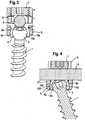
- Fig. 4
- shows a sectional view of the bone anchoring device in an assembled and fixed state, the section being taken along the rod axis.
- Fig. 5
- shows a perspective view of the receiving part.
- Fig. 6
- shows a side view of the receiving part.
- Fig. 7
- shows a top view of the receiving part.
- Fig. 8
- shows a side view of the receiving part rotated by 90°.
- Fig. 9
- shows a bottom view of the receiving part.
- Fig. 10
- shows a partly sectional view of the bone anchoring device in a condition, in which the bone anchoring element is still pivotable.
- Fig. 11
- shows a partly sectional view of the bone anchoring device in a condition, in which the head of the bone anchoring element is locked.
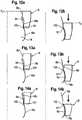
- Fig. 12a
- shows a schematic view of a preliminary locking position of the locking ring.
- Fig. 12b
- shows a locking position of the locking ring.
- Fig. 13a
- shows a preliminary position of a modified locking ring.
- Fig. 13b
- shows a locking position of a modified locking ring.
- Fig. 14a
- shows a preliminary locking position of a further modified locking ring.
- Fig. 14b
- shows a locking position of the further modified locking ring.
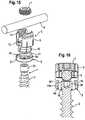
- Fig. 15
- shows an exploded perspective view of a second embodiment of the bone anchoring device.
- Fig. 16
- shows a sectional view of the second embodiment in an assembled and fixed state, the section being taken perpendicular to the rod axis.
- Fig. 17
- shows a sectional view of the receiving part according to the invention.
- Fig. 18
- shows a sectional view of the bone anchoring device according to the invention, the section being taken along the rod axis.
- As shown in
Figs. 1 to 4 , the bone anchoring device according to a first embodiment comprises abone anchoring element 1 in the form of a bone screw having a threadedshaft 2 and ahead 3 with a curved surface portion, in this embodiment a spherical segment-shaped head. Thehead 3 has a recess 4 for engagement with a screwing-in tool. The bone anchoring device further comprises a receivingpart body 5 for receiving arod 6 to connect it to thebone anchoring element 1. Further, a closure element 7 in the form of an inner screw is provided for securing therod 6 in the receivingpart body 5. In addition, the bone anchoring device comprises alocking ring 8 for locking the head in the receivingpart body 5. - As can be seen in particular in
Figs. 5 to 9 , the receivingpart body 5 comprises arod receiving portion 9, which is substantially cylindrical and which has afirst end 9a, an oppositesecond end 9b. Therod receiving portion 9 has a coaxialfirst bore 10 provided at thesecond end 9b. The diameter of thefirst bore 10 is smaller than the diameter of thehead 3 of the bone anchoring element. Therod receiving portion 9 also comprises a coaxialsecond bore 11 extending from thefirst end 9a to a distance from thesecond end 9b. The diameter of thesecond bore 11 is larger than that of thefirst bore 10 and larger than the diameter of therod 6. A substantiallyU-shaped recess 12 is provided in therod receiving portion 9, which extends from thefirst end 9a to thesecond end 9b, the diameter of therecess 12 being slightly larger than the diameter of therod 6 in such a way that therod 6 can be placed in the recess and can be guided therein. By means of therecess 12 tofree legs internal thread 13 is provided. Theinternal thread 13 can be a metric thread, a flat thread, a negative angle thread, a saw-tooth thread or any other thread type. Preferably, a thread form such as a flat thread or negative angle thread is used, which prevents splaying of thelegs recess 12 is such that therod 6 and the inner screw 7 can be inserted between the legs. Between the bottom of therecess 12 and thelegs flat section 14 is provided forming the end of thebore 11. - As can be seen in
Figs. 1 ,5 and 7 , cuts 24 are provided in the rod receiving portion on either end of the channel formed by therecess 12. - The
rod receiving portion 9 of the receivingpart body 5 further comprises a plurality ofcoaxial slits 15 extending from thesecond end 9b to a distance from the first end, wherein the distance corresponds approximately to the length of theinternal thread 13. Theslits 15 are open at thesecond end 9b and extend, as can be seen in particular inFigs. 5, 7 and 9 , through theflat section 14 and the substantiallyU-shaped recess 12. At least one slit 15, preferably more than slit, is provided on either side of therecess 12. The number of slits is provided according to the degree of flexibility, which shall be provided by the slits. It may depend on the material and the wall thickness and/or other factors. - Adjacent to the
second end 9b, the receivingpart body 5 comprises ahead receiving portion 16 providing an accommodation space for thehead 3 of thebone anchoring element 5. Thehead receiving portion 16 has anopen end 17 opposite to thesecond end 9b and anexterior surface 18. Theopen end 17 can have a rounded edge. As can be seen in particular inFig. 6 , the outer diameter of therod receiving portion 9 at itssecond end 9b is larger than the outer diameter of thehead receiving portion 16 adjacent to thesecond end 9b and is also larger than the outer diameter of the head receiving portion at theopen end 17. Hence, thehead receiving portion 16 is recessed with respect to therod receiving portion 9. Theexterior surface 18 of thehead receiving portion 16 has a firstcurved portion 18a and a secondcurved portion 18b with an outwardly directed curvature. The outer diameter of the secondcurved portion 18b is smaller than the outer diameter of the firstcurved portion 18a. In the embodiment shown, the curvature is substantially spherically-shaped. At the transition from the curvedfirst surface portion 18a and the curvedsecond surface portion 18b agroove 100 is formed. - As can be seen in particular in
Figs. 3 and 4 , thehead receiving portion 16 has an internalhollow section 18c forming a seat for thehead 3 of thebone anchoring element 1. Thehollow section 18 is adapted in its shape to the shape of thehead 3, in the embodiment shown, it is a spherical section to accommodate thespherical head 3. Thehollow section 18c is dimensioned in such a way that it encompasses thehead 3 of the bone anchoring element from the side covering a region including the largest diameter of thehead 3. - As can be seen in particular in
Figs. 1, 2 and5 to 9 , a plurality ofslits 19 are provided in thehead receiving portion 16 which are open to theopen end 17 and extend from theopen end 17 to thesecond end 9b of the rod receiving portion and which continue in theslits 15 of therod receiving portion 9, thereby forming continuous slits extending from theopen end 17 of the head receiving portion into the rod receiving portion. The number ofslits 19 may be equal to the number ofslits 15, however, it can be smaller or larger depending on the desired flexibility of thehead receiving portion 16. In addition, slits 20 are provided on the side of thehead receiving portion 16 which is adjacent to the substantiallyU-shaped recess 12 of the rod receiving portion as shown inFig. 6 . Theslits 20 end at a distance of thesecond end 9b. The flexibility of thehead receiving portion 16 is such that thehead 3 of the anchoring element can be inserted by expanding the head receiving portion and can be clamped by compressing the head receiving portion. Theslits 15 in the rod receiving portion facilitate mounting of the receivingpart body 5 onto thehead 3 manually, for example, at any time before or during surgery. - The locking ring will now be described with reference to
Figs. 1 to 4 . Thelocking ring 8 has a substantially cylindrical outer surface with an outer diameter corresponding substantially to the outer diameter of therod receiving portion 9 of the receivingpart body 5. The height of thelocking ring 8 in an axial direction is smaller than that of thehead receiving portion 16 of the receivingpart body 5, so that, as shown in particular inFig. 3 , there is a distance between the locking ring and asecond end 9b of the receivingpart 5 in which thehead 3 is locked. As shown inFigs. 1 and3 to 4 , thelocking ring 8 has on its inner side a firstinterior surface portion 8a which is curved. The curvature is directed outward from the center of the locking ring. In the embodiment shown, the curved firstinterior surface portion 8a has a spherical curvature which is sized to fit to the first curvedexterior surface portion 18a of the head receiving portion. The radius of the curvature is preferably smaller than the radius of thehead 3. The dimensions of the locking ring with respect to its inner portions are such that thelocking ring 8 can be moved along the outer surface of thehead receiving portion 16 thereby compressing thehead receiving portion 16 when moving downward. - Adjacent to the curved first
interior surface portion 8a, the locking ring may have a curved secondinterior surface portion 8b with a curvature corresponding to that of the second curvedexterior surface portion 18b of thehead receiving portion 16. At the transition between the firstinterior surface portion 8a and the secondinterior surface portion 8b acircular edge 101 is ' formed as shown inFigs 10 and12 . In addition, opposite to the curved secondinterior surface portion 8b the locking ring may have athird portion 8c with a diameter increasing towards the free end of the locking ring. - As can be seen in particular in
Figs. 1 and4 , thelocking ring 8 further comprises on its side facing thesecond end 9b, twoprojections 21 located diametrically opposite to each other. Theprojections 21 have such a height that they project above the bottom of the substantiallyU-shaped recess 12 and extend into thecuts 24, when thelocking ring 8 is in a position in which thehead 3 is not yet clamped. Thefree end 22 of theprojections 21 can be curved, particularly inwardly curved, with a curvature corresponding to that of therod 6. The locking ring is arranged in such a way around thehead receiving portion 16 of the receivingpart body 5 that the projections are located at the positions of therecess 12. By means of this, theprojections 21 which project into therecess 12, prevent the locking ring from rotating when the rod is not inserted. - The flexibility of the
head receiving portion 16 and the size of the head receiving portion at theopen end 17 allows to mount thelocking ring 8 by assembling it from thefree end 17 onto thehead receiving portion 16. Since the outer diameter of the head receiving portion is smaller than that of therod receiving portion 9, the locking ring does not project or only minimally projects beyond the rod receiving portion in a radial direction. - The inner screw 7 has a thread corresponding to the
internal thread 13 provided on thelegs - The receiving
part body 5, thelocking ring 8, the inner screw 7 and thebone anchoring element 1 are made of a bio-compatible material, for example, of titanium or stainless steel or a bio-compatible alloy or bio-compatible plastic material with sufficient strength. - The bone anchoring device may be pre-assembled with a
locking ring 8 mounted on thehead receiving portion 16 of the receivingpart body 5 from theopen end 17. Alternatively, thebone anchoring element 1 can be pre-assembled with the receivingpart 5 and thelocking ring 8. - The locking of the
head 3 is now explained with respect toFigs. 10 to 12 . When the rod is not yet inserted or not pressed into therecess 12, the locking ring is movable between a first position P1, in which it abuts against thesecond end 9b of the rod receiving part which acts as a stop (not shown), and a second position P2 near theopen end 17 of the head receiving portion as shown inFigs. 11 and12b , which is defined by the locking of thehead 3 by means of compression of the head receiving portion. In this position P2 as shown inFig. 11 andFig. 12b , the curvedinterior surface portion 8a of the locking ring presses onto the first curvedexterior surface portion 18a of the head receiving portion to clamp the head by means of compression of the head receiving portion. The dimensions of the locking ring and the head receiving portion are such that the matching curvedfirst surface portions head 3. As shown inFig. 11 andFig. 12b in the locking position P2 also the secondcurved portion 8b of the locking ring and 18b of the head receiving portion oppose each other. Theedge 101 engages thegroove 100 so that a form fit force contribution for the locking of the head is provided. This forms an obstacle, when the locking ring is moved in the direction of the first end position P1 which enhances the safe clamping of thehead 3 in the locking position P2. - Means for temporarily and releasably holding the locking ring in the first position P1 may be provided (not shown). This can be a catch, for example.
- Depending on the dimensions of the curvatures and the radii of the curved portions, there may be a third intermediate position P3 as shown in
Fig. 12a in which the lower end of thecurved surface portion 8a of the locking ring engages thegroove 100 between the two curved exterior surface portions of the head receiving portion. In this way, the locking ring is in a loosely held position, in which it also may exert a slight compression force onto the head receiving portion to allow a preliminary locking of thehead 3. - The bone anchoring device can be used in several ways. In one way of use, the bone anchoring element, the receiving part body and the locking ring are pre-assembled. The bone anchoring element is screwed into the bone with the receiving part mounted to the anchoring element. The recess 4 of the head can be accessed with the screwing-in tool through the
first bore 10. The locking ring is in its first position close to thesecond end 9b, where it does not clamp thehead 3. The flexible receiving part creates a slight pretension having a small overlap on the inner curved surface of thehollow portion 18c. In this state the head is pivotably held in thesecond portion 16, which allows the receivingpart body 5 to be safely aligned to receive the rod. Once the correct position of the rod with respect to other bone anchoring devices is achieved, the inner screw 7 is screwed between the legs until it presses onto the rod. The rod is pressed against the bottom of the substantially U-shaped recess, thereby engaging the free ends 22 of theprojections 21, respectively, and shifting down the locking ring. When the locking ring is moved, it reaches the intermediate position P3, in which a preliminary locking of thehead 3 is possible. When it further moves towards thefree end 17 of the head receiving portion, it compresses thehead receiving portion 16 thereby clamping the head. The force clamping the head is generated by the frictional force between the locking ring and the head receiving portion. - As shown in
Figs. 11 and12b , the end position P2 is secured in addition by a form-fit contribution generated by the engagement of theedge 101 with thegroove 100. Since the force, which is exerted by the locking ring, acts with the interiorcurved surface 8a from the lateral side, the force necessary for safely immobilizing the head is smaller than in the case in which the force acts from above on the top of thehead 3. It also allows to downsize the device by allowing the wall thickness of the receiving part to be reduced. Final tightening of the inner screw locks the rod and the head simultaneously. - In another way of use, only the receiving
part body 5 and thelocking ring 8 are pre-assembled. Thebone anchoring element 3 is first screwed into the bone and then the receiving part is mounted onto thehead 3, while the locking ring is in its first position close to thesecond end 9b and does not compress thesecond portion 16. Alternatively, thebone anchoring element 1 and the receiving part body with the pre-assembled locking ring are assembled by pressing the receiving part onto thehead 3. This allows to select the appropriate bone anchoring element in terms of diameter, length and other features of the anchoring section. Hence, a modular system can be provided including receiving parts and several bone anchoring elements, which then individually can be chosen and adapted. - In yet another way of use, the inner screw is tightened to lock the head and the rod. Thereafter, the inner screw is loosened to allow further adjustments of the rod. The head remains temporarily clamped due to the frictional force and the shape of the curvatures, which holds the locking ring in place.
- In
Figures 13a and 13b the interaction between a modified locking ring 8' and the head receiving portion is schematically shown. The modified locking ring 8' has instead of the second curvedinterior surface portion 8b a conically wideninginterior portion 8b'. At the transition between thecurved portion 8a and the conically wideningportion 8b' anedge 101 is built in the same way as in the previous embodiment, which engages in thegroove 100 formed at the transition between the curvedfirst surface portion 18a and the curvedsecond surface portion 18b of the head receiving portion. - In
Fig. 14a and 14b a further modification of the locking ring, which cooperates with the head receiving portion is schematically shown. Thelocking ring 8" has only an interiorcurved portion 8a, the other etch of which forms theetch 100, which engages into thegroove 101 formed between the first curvedexterior surface portion 18a and the second curvedexterior surface portion 18b of the head receiving portion. Figures 15 and 16 show a second embodiment of the bone anchoring device. Portions and elements, which are identical to the first embodiment and the modifications, are designated with the same reference numerals as in the description of the first embodiment. The description thereof will not be repeated.- The second embodiment differs from the first embodiment only with respect to the bone anchoring element and the hollow space in the
head receiving portion 16 of the receivingpart body 5. The bone anchoring element 1' has a threadedshaft 2 and acylindrical head 30. The hollow portion 18' is cylindrically-shaped and has a diameter, which is slightly larger than the diameter of thecylindrical head 30 in such a way that thecylindrical head 30 can be inserted and guided in the hollow portion 18' in the unlocked state. Theend 181 of the cylindrical hollow portion forms a stop for thehead 30. The use of the bone anchoring device according to the second embodiment is similar to that of the first embodiment. The difference is that the receivingpart 5 can not pivot relative to the bone anchoring element 1' but can only rotate in the unclamped stead of thehead 30. This monoaxial rotatable connection between the receivingpart body 5 and the bone anchoring element 1' may be useful in certain anatomical situations. It allows the receiving part to be aligned with respect to the rod by only rotating it around the screw axis. Figs. 17 and 18 show the invention. Portions and elements, which are identical to the first and second embodiment, are designated with the same reference numerals and the detailed description thereof will not be repeated. The receiving part body 5' of the third embodiment comprises an inclined free end 17' of thehead receiving portion 16. As can be seen in particular inFig. 17 , the inclined free end 17' defines a plane, which includes an angle with the plane defined by thefirst end 9a of the rod receiving portion of the receivingpart body 5. Thehollow portion 18", which accommodates thehead 3, is therefore shorter on one side compared to the opposite side.- As can be seen in
Fig. 18 , this results in a larger pivot angle to one side as compared to the opposite side. Hence, a polyaxial screw with an asymmetric pivot angle range is provided. The inclined free end 17' can be easily manufactured by cutting. - Further modifications of the embodiment described are possible. For example, the head of the bone anchoring element can have any other shape, such as, for example, a conical shape. The internal
hollow portion 18 of the head receiving portion can be adapted to the shape of the head. In a further modification, the receivingpart body 5 or at least thehead receiving portion 16 are made of a bio-compatible plastic material, which provides elasticity to a certain degree. In this case, the slits may be omitted. - The projections of the locking ring, which engage the rod, can have any other shape. For example, the surface of the free end can be flat or otherwise shaped. In a further modification, the projections are omitted.
- The curvature of the cooperating surfaces of the head receiving portion and the locking ring can be other than spherical. The radii of the curvature can be the same or can be different.
Claims (15)
- A receiving part for receiving a rod for coupling the rod to a bone anchoring element, the receiving part including
a receiving part body (5') with
a rod receiving portion (9) with a first end (9a) and a second end (9b) and with a channel (12) for receiving the rod, and
a head receiving portion (16) at the side of the second end (9b) for accommodating a head (3, 30) of the bone anchoring element, the head receiving portion having an open free end (17') and being flexible so as to allow introduction and clamping of the head, the head receiving portion having an exterior surface with a curved portion; and
a locking ring (8, 8', 8") embracing the head receiving portion (16);
characterized in that the locking ring has an interior surface with a curved portion (8a), which presses against the curved portion of the exterior surface of the head receiving portion (16) to clamp the head, and wherein the free end (17') of the head receiving portion (16) is inclined and defines a plane, which includes an angle with the plane defined by the first end (9a) of the rod receiving portion (5'). - The receiving part of claim 1, wherein the curved portion (18a) of the head receiving portion is curved in an outward direction relative to the center of the head receiving portion.
- The receiving part of claim 1 or 2, wherein the curved portion (8a) of the locking ring is curved in an outward direction relative to the center of the locking ring (8, 8', 8").
- The receiving part of one of claims 1 to 3, wherein the head receiving portion (16) comprises a second curved portion (18b) adjacent to the first curved portion (18a) thereby forming a groove (100) between the curved portions.
- The receiving part of claim 4, wherein the end of the curved portion of the locking ring forms an edge (101) cooperating with the groove (100) of the head receiving portion.
- The receiving part of one of claims 1 to 5, wherein the locking ring (8, 8', 8") is movable between a first position (Pi), in which the head receiving portion is not compressed so as to allow movement of the head (3) and a second position (P2), in which the head is clamped in such a way that it is locked.
- The receiving part of claim 6, wherein the locking ring (8, 8', 8") engages the head receiving portion (16) in the second position (P2) in a form locking manner.
- The receiving part of one of claims 1 to 7, wherein the head (3) has a curved outer surface portion and wherein a radius of the curved portion (8a) of the locking ring (8, 8', 8") is smaller than a radius of the curved surface portion of the head (3).
- The receiving part of one of claims 1 to 8, wherein the locking ring (8, 8', 8") is movable upon exerting a pressure onto it via the rod.
- The receiving part of one of claims 1 to 9, wherein the rod receiving portion (9) has a recess (12) extending from the first end (9a) in the direction of the second end (9b), which forms the channel for the rod.
- The receiving part of one of claims 1 to 10, wherein the outer diameter of the head receiving portion (16) at the side of the second end (9b) is smaller than the diameter of the rod receiving portion (9) at the second end (9b).
- The receiving part of one of claims 1 to 11, wherein the head receiving portion (9) comprises a plurality of slits (19, 20) being open to the open end (17).
- The receiving part of one of claims 1 to 12, wherein the rod receiving portion (9) comprises a plurality of slits (15) extending from a distance from the first end (9a) to the second end (9b), preferably at least one of the slits is a continuous slit (15, 19) extending from the open end (17) of the head receiving portion (16) into the rod receiving portion (9).
- A bone anchoring device comprising a receiving part according to one of claims 1 to 13 and a bone anchoring element (1) having a threaded shaft and a head (3, 30).
- The bone anchoring device according to claim 14, wherein a closure element (7) preferably an inner screw, is provided for securing the rod (6) in the recess (12).
Priority Applications (1)
| Application Number | Priority Date | Filing Date | Title |
|---|---|---|---|
| EP12181740.7AEP2526881B1 (en) | 2008-12-29 | 2008-12-29 | Receiving part for receiving a rod for coupling the rod to a bone anchoring element and bone anchoring device with such a receiving part |
Applications Claiming Priority (2)
| Application Number | Priority Date | Filing Date | Title |
|---|---|---|---|
| EP12181740.7AEP2526881B1 (en) | 2008-12-29 | 2008-12-29 | Receiving part for receiving a rod for coupling the rod to a bone anchoring element and bone anchoring device with such a receiving part |
| EP20080022510EP2201903B1 (en) | 2008-12-29 | 2008-12-29 | Receiving part for receiving a rod for coupling the rod to a bone anchoring element and bone anchoring device with such a receiving part |
Related Parent Applications (2)
| Application Number | Title | Priority Date | Filing Date |
|---|---|---|---|
| EP08022510.5Division | 2008-12-29 | ||
| EP20080022510DivisionEP2201903B1 (en) | 2008-12-29 | 2008-12-29 | Receiving part for receiving a rod for coupling the rod to a bone anchoring element and bone anchoring device with such a receiving part |
Publications (3)
| Publication Number | Publication Date |
|---|---|
| EP2526881A2 EP2526881A2 (en) | 2012-11-28 |
| EP2526881A3 EP2526881A3 (en) | 2012-12-19 |
| EP2526881B1true EP2526881B1 (en) | 2020-11-25 |
Family
ID=40521840
Family Applications (2)
| Application Number | Title | Priority Date | Filing Date |
|---|---|---|---|
| EP20080022510ActiveEP2201903B1 (en) | 2008-12-29 | 2008-12-29 | Receiving part for receiving a rod for coupling the rod to a bone anchoring element and bone anchoring device with such a receiving part |
| EP12181740.7AActiveEP2526881B1 (en) | 2008-12-29 | 2008-12-29 | Receiving part for receiving a rod for coupling the rod to a bone anchoring element and bone anchoring device with such a receiving part |
Family Applications Before (1)
| Application Number | Title | Priority Date | Filing Date |
|---|---|---|---|
| EP20080022510ActiveEP2201903B1 (en) | 2008-12-29 | 2008-12-29 | Receiving part for receiving a rod for coupling the rod to a bone anchoring element and bone anchoring device with such a receiving part |
Country Status (7)
| Country | Link |
|---|---|
| US (2) | US8636782B2 (en) |
| EP (2) | EP2201903B1 (en) |
| JP (1) | JP5622387B2 (en) |
| KR (1) | KR101559859B1 (en) |
| CN (1) | CN101791245B (en) |
| ES (1) | ES2423676T3 (en) |
| TW (1) | TWI531349B (en) |
Families Citing this family (71)
| Publication number | Priority date | Publication date | Assignee | Title |
|---|---|---|---|---|
| US7833250B2 (en) | 2004-11-10 | 2010-11-16 | Jackson Roger P | Polyaxial bone screw with helically wound capture connection |
| US7862587B2 (en) | 2004-02-27 | 2011-01-04 | Jackson Roger P | Dynamic stabilization assemblies, tool set and method |
| US8876868B2 (en) | 2002-09-06 | 2014-11-04 | Roger P. Jackson | Helical guide and advancement flange with radially loaded lip |
| US7621918B2 (en) | 2004-11-23 | 2009-11-24 | Jackson Roger P | Spinal fixation tool set and method |
| US7377923B2 (en) | 2003-05-22 | 2008-05-27 | Alphatec Spine, Inc. | Variable angle spinal screw assembly |
| US7766915B2 (en) | 2004-02-27 | 2010-08-03 | Jackson Roger P | Dynamic fixation assemblies with inner core and outer coil-like member |
| US8926670B2 (en) | 2003-06-18 | 2015-01-06 | Roger P. Jackson | Polyaxial bone screw assembly |
| US7776067B2 (en) | 2005-05-27 | 2010-08-17 | Jackson Roger P | Polyaxial bone screw with shank articulation pressure insert and method |
| US11419642B2 (en) | 2003-12-16 | 2022-08-23 | Medos International Sarl | Percutaneous access devices and bone anchor assemblies |
| US7179261B2 (en) | 2003-12-16 | 2007-02-20 | Depuy Spine, Inc. | Percutaneous access devices and bone anchor assemblies |
| US7527638B2 (en) | 2003-12-16 | 2009-05-05 | Depuy Spine, Inc. | Methods and devices for minimally invasive spinal fixation element placement |
| US11241261B2 (en) | 2005-09-30 | 2022-02-08 | Roger P Jackson | Apparatus and method for soft spinal stabilization using a tensionable cord and releasable end structure |
| US8152810B2 (en) | 2004-11-23 | 2012-04-10 | Jackson Roger P | Spinal fixation tool set and method |
| US7160300B2 (en) | 2004-02-27 | 2007-01-09 | Jackson Roger P | Orthopedic implant rod reduction tool set and method |
| JP2007525274A (en) | 2004-02-27 | 2007-09-06 | ロジャー・ピー・ジャクソン | Orthopedic implant rod reduction instrument set and method |
| US8926672B2 (en) | 2004-11-10 | 2015-01-06 | Roger P. Jackson | Splay control closure for open bone anchor |
| US8444681B2 (en) | 2009-06-15 | 2013-05-21 | Roger P. Jackson | Polyaxial bone anchor with pop-on shank, friction fit retainer and winged insert |
| US9168069B2 (en) | 2009-06-15 | 2015-10-27 | Roger P. Jackson | Polyaxial bone anchor with pop-on shank and winged insert with lower skirt for engaging a friction fit retainer |
| US9980753B2 (en) | 2009-06-15 | 2018-05-29 | Roger P Jackson | pivotal anchor with snap-in-place insert having rotation blocking extensions |
| WO2006057837A1 (en) | 2004-11-23 | 2006-06-01 | Jackson Roger P | Spinal fixation tool attachment structure |
| US7901437B2 (en) | 2007-01-26 | 2011-03-08 | Jackson Roger P | Dynamic stabilization member with molded connection |
| CA2670988C (en) | 2006-12-08 | 2014-03-25 | Roger P. Jackson | Tool system for dynamic spinal implants |
| US10792074B2 (en) | 2007-01-22 | 2020-10-06 | Roger P. Jackson | Pivotal bone anchor assemly with twist-in-place friction fit insert |
| US8979904B2 (en) | 2007-05-01 | 2015-03-17 | Roger P Jackson | Connecting member with tensioned cord, low profile rigid sleeve and spacer with torsion control |
| ES2348814T3 (en) | 2007-07-31 | 2010-12-15 | Biedermann Motech Gmbh | ANCHORAGE DEVICE Ã “SEO. |
| AU2010260521C1 (en) | 2008-08-01 | 2013-08-01 | Roger P. Jackson | Longitudinal connecting member with sleeved tensioned cords |
| US11229457B2 (en) | 2009-06-15 | 2022-01-25 | Roger P. Jackson | Pivotal bone anchor assembly with insert tool deployment |
| US8998959B2 (en) | 2009-06-15 | 2015-04-07 | Roger P Jackson | Polyaxial bone anchors with pop-on shank, fully constrained friction fit retainer and lock and release insert |
| US9668771B2 (en) | 2009-06-15 | 2017-06-06 | Roger P Jackson | Soft stabilization assemblies with off-set connector |
| CN103826560A (en) | 2009-06-15 | 2014-05-28 | 罗杰.P.杰克逊 | Polyaxial Bone Anchor with Socket Stem and Winged Inserts with Friction Fit Compression Collars |
| EP2485654B1 (en) | 2009-10-05 | 2021-05-05 | Jackson P. Roger | Polyaxial bone anchor with non-pivotable retainer and pop-on shank, some with friction fit |
| EP2384709B1 (en) | 2010-05-05 | 2012-09-05 | Biedermann Technologies GmbH & Co. KG | Receiving part for receiving a rod for coupling the rod to a bone anchoring element, bone anchoring device, method and tool for assembling the same |
| US12383311B2 (en) | 2010-05-14 | 2025-08-12 | Roger P. Jackson | Pivotal bone anchor assembly and method for use thereof |
| AU2011324058A1 (en) | 2010-11-02 | 2013-06-20 | Roger P. Jackson | Polyaxial bone anchor with pop-on shank and pivotable retainer |
| EP2514378B1 (en) | 2010-12-10 | 2015-02-18 | Biedermann Technologies GmbH & Co. KG | Bone anchoring device |
| EP2737864B1 (en)* | 2010-12-10 | 2017-04-12 | Biedermann Technologies GmbH & Co. KG | Receiving part for receiving a rod for coupling the rod to a bone anchoring element and a bone anchoring device |
| EP2462888B1 (en)* | 2010-12-10 | 2015-02-18 | Biedermann Technologies GmbH & Co. KG | Receiving part for receiving a rod for coupling the rod to a bone anchoring element and bone anchoring device with such a receiving part |
| ES2399983T3 (en) | 2010-12-23 | 2013-04-04 | Biedermann Technologies Gmbh & Co. Kg | Stabilization device for vertebrae or bone parts |
| JP5865479B2 (en) | 2011-03-24 | 2016-02-17 | ロジャー・ピー・ジャクソン | Multiaxial bone anchor with compound joint and pop-mounted shank |
| EP2918237A1 (en)* | 2011-09-15 | 2015-09-16 | Biedermann Technologies GmbH & Co. KG | Polyaxial bone anchoring device with enlarged pivot angle |
| EP2574297B1 (en)* | 2011-09-30 | 2015-11-11 | Biedermann Technologies GmbH & Co. KG | Bone anchoring device and tool cooperating with such a bone anchoring device |
| US8911479B2 (en) | 2012-01-10 | 2014-12-16 | Roger P. Jackson | Multi-start closures for open implants |
| ES2552987T3 (en)* | 2012-07-03 | 2015-12-03 | Biedermann Technologies Gmbh & Co. Kg | Polyaxial bone anchoring device |
| EP2911599B1 (en)* | 2012-10-23 | 2020-04-29 | Nexus Spine, L.L.C. | Surgical construct coupling system |
| US8911478B2 (en) | 2012-11-21 | 2014-12-16 | Roger P. Jackson | Splay control closure for open bone anchor |
| US10058354B2 (en) | 2013-01-28 | 2018-08-28 | Roger P. Jackson | Pivotal bone anchor assembly with frictional shank head seating surfaces |
| US8852239B2 (en) | 2013-02-15 | 2014-10-07 | Roger P Jackson | Sagittal angle screw with integral shank and receiver |
| US9566092B2 (en) | 2013-10-29 | 2017-02-14 | Roger P. Jackson | Cervical bone anchor with collet retainer and outer locking sleeve |
| US9649135B2 (en)* | 2013-11-27 | 2017-05-16 | Spinal Llc | Bottom loading low profile fixation system |
| US9717533B2 (en) | 2013-12-12 | 2017-08-01 | Roger P. Jackson | Bone anchor closure pivot-splay control flange form guide and advancement structure |
| US9451993B2 (en) | 2014-01-09 | 2016-09-27 | Roger P. Jackson | Bi-radial pop-on cervical bone anchor |
| US10918419B2 (en) | 2014-04-01 | 2021-02-16 | K2M, Inc. | Spinal fixation device |
| US20150297266A1 (en)* | 2014-04-21 | 2015-10-22 | X-Spine Systems, Inc. | Modular multi-axial screw system |
| US10064658B2 (en) | 2014-06-04 | 2018-09-04 | Roger P. Jackson | Polyaxial bone anchor with insert guides |
| US9597119B2 (en) | 2014-06-04 | 2017-03-21 | Roger P. Jackson | Polyaxial bone anchor with polymer sleeve |
| US9707013B2 (en)* | 2015-04-30 | 2017-07-18 | Warsaw Orthopedic, Inc. | Spinal implant system and methods of use |
| EP3106110B1 (en) | 2015-06-16 | 2017-10-11 | Biedermann Technologies GmbH & Co. KG | Extension device for a bone anchor |
| EP3120791B1 (en)* | 2015-07-24 | 2017-11-22 | Biedermann Technologies GmbH & Co. KG | Polyaxial bone anchoring device and instrument for use with the same |
| US10278687B2 (en)* | 2015-08-18 | 2019-05-07 | Globus Medical, Inc. | Devices and systems for surgical retraction |
| CN106002428A (en)* | 2016-06-20 | 2016-10-12 | 昆山鸿福泰环保科技有限公司 | Novel receiving internal rod |
| DE102017101348A1 (en)* | 2017-01-25 | 2018-07-26 | Aesculap Ag | Axis accurate screwdriver |
| WO2018183486A1 (en) | 2017-03-30 | 2018-10-04 | K2M, Inc. | Modular offset screw |
| US11298156B2 (en) | 2017-03-30 | 2022-04-12 | K2M, Inc. | Modular screw |
| AU2018243875B2 (en) | 2017-03-30 | 2022-05-26 | K2M, Inc. | Bone anchor apparatus and method of use thereof |
| US10258386B2 (en)* | 2017-06-15 | 2019-04-16 | Warsaw Orthopedic, Inc. | Spinal construct and method |
| US11571244B2 (en) | 2019-05-22 | 2023-02-07 | Nuvasive, Inc. | Posterior spinal fixation screws |
| EP3871624B1 (en) | 2020-02-25 | 2023-07-19 | Biedermann Technologies GmbH & Co. KG | Bone anchoring device |
| EP3878386B1 (en) | 2020-03-12 | 2023-08-30 | Biedermann Technologies GmbH & Co. KG | Coupling device for use with a bone anchoring element and bone anchoring device with such a coupling device |
| WO2021263088A1 (en) | 2020-06-26 | 2021-12-30 | K2M, Inc. | Modular head assembly |
| WO2022108875A1 (en) | 2020-11-19 | 2022-05-27 | K2M, Inc. | Modular head assembly for spinal fixation |
| EP4129220B1 (en)* | 2021-08-04 | 2024-07-03 | Biedermann Technologies GmbH & Co. KG | Coupling device for coupling a rod to a bone anchoring element and method of manufacturing the same |
Citations (1)
| Publication number | Priority date | Publication date | Assignee | Title |
|---|---|---|---|---|
| WO2007038350A2 (en)* | 2005-09-23 | 2007-04-05 | Synthes (Usa) | Bone support apparatus |
Family Cites Families (32)
| Publication number | Priority date | Publication date | Assignee | Title |
|---|---|---|---|---|
| US5549608A (en) | 1995-07-13 | 1996-08-27 | Fastenetix, L.L.C. | Advanced polyaxial locking screw and coupling element device for use with rod fixation apparatus |
| US5578033A (en) | 1995-07-13 | 1996-11-26 | Fastenetix, L.L.C. | Advanced polyaxial locking hook and coupling element device for use with side loading rod fixation devices |
| US5586984A (en) | 1995-07-13 | 1996-12-24 | Fastenetix, L.L.C. | Polyaxial locking screw and coupling element assembly for use with rod fixation apparatus |
| US5609593A (en) | 1995-07-13 | 1997-03-11 | Fastenetix, Llc | Advanced polyaxial locking hook and coupling element device for use with top loading rod fixation devices |
| US5733285A (en) | 1995-07-13 | 1998-03-31 | Fastenetix, Llc | Polyaxial locking mechanism |
| US5584834A (en) | 1995-07-13 | 1996-12-17 | Fastenetix, L.L.C. | Polyaxial locking screw and coupling element assembly for use with side loading rod fixation apparatus |
| US5964760A (en) | 1996-10-18 | 1999-10-12 | Spinal Innovations | Spinal implant fixation assembly |
| US5728098A (en) | 1996-11-07 | 1998-03-17 | Sdgi Holdings, Inc. | Multi-angle bone screw assembly using shape-memory technology |
| US6371957B1 (en)* | 1997-01-22 | 2002-04-16 | Synthes (Usa) | Device for connecting a longitudinal bar to a pedicle screw |
| US6010503A (en) | 1998-04-03 | 2000-01-04 | Spinal Innovations, Llc | Locking mechanism |
| PT1117336E (en) | 1998-09-29 | 2004-10-29 | Synthes Ag | DEVICE FOR CONNECTING A LONGITUDINAL SUPPORT TO A BONUS FIXATION MEANS |
| US6254602B1 (en) | 1999-05-28 | 2001-07-03 | Sdgi Holdings, Inc. | Advanced coupling device using shape-memory technology |
| JP4130411B2 (en) | 2002-02-11 | 2008-08-06 | ジンテーズ ゲゼルシャフト ミト ベシュレンクテル ハフツング | Device for joining the vertical support and bone |
| US20060200128A1 (en) | 2003-04-04 | 2006-09-07 | Richard Mueller | Bone anchor |
| US20050080415A1 (en) | 2003-10-14 | 2005-04-14 | Keyer Thomas R. | Polyaxial bone anchor and method of spinal fixation |
| US7090674B2 (en)* | 2003-11-03 | 2006-08-15 | Spinal, Llc | Bone fixation system with low profile fastener |
| US7503924B2 (en) | 2004-04-08 | 2009-03-17 | Globus Medical, Inc. | Polyaxial screw |
| US7491207B2 (en)* | 2004-04-12 | 2009-02-17 | Synthes Usa, Llc | Rod persuader |
| US20060161153A1 (en) | 2004-10-25 | 2006-07-20 | Alphaspine, Inc. | Pedicle screw systems and methods of assembling/installing the same |
| JP2006129037A (en)* | 2004-10-28 | 2006-05-18 | Pioneer Electronic Corp | Speaker damper |
| TWI375545B (en) | 2005-04-25 | 2012-11-01 | Synthes Gmbh | Bone anchor with locking cap and method of spinal fixation |
| WO2008137933A1 (en) | 2005-05-25 | 2008-11-13 | Alpinespine Llc | Low rider pedicle screw system |
| US7988694B2 (en) | 2005-09-29 | 2011-08-02 | K2M, Inc. | Spinal fixation system having locking and unlocking devices for use with a multi-planar, taper lock screw |
| EP2078506A4 (en)* | 2006-06-05 | 2011-11-09 | Traiber S L | Device for vertebral attachment and tool for fitting of the said device |
| US8162991B2 (en) | 2006-07-27 | 2012-04-24 | K2M, Inc. | Multi-planar, taper lock screw |
| ES2348814T3 (en)* | 2007-07-31 | 2010-12-15 | Biedermann Motech Gmbh | ANCHORAGE DEVICE Ã “SEO. |
| DE102007042958B4 (en) | 2007-08-30 | 2015-03-19 | Aesculap Ag | Surgical holding system |
| US8038701B2 (en) | 2007-10-22 | 2011-10-18 | K2M, Inc. | Uni-planar, taper lock bone screw |
| US8287576B2 (en) | 2007-10-23 | 2012-10-16 | K2M, Inc. | Mono-axial, taper lock bone screw |
| US20090105756A1 (en) | 2007-10-23 | 2009-04-23 | Marc Richelsoph | Spinal implant |
| US8398683B2 (en) | 2007-10-23 | 2013-03-19 | Pioneer Surgical Technology, Inc. | Rod coupling assembly and methods for bone fixation |
| US7789900B2 (en) | 2007-12-04 | 2010-09-07 | Expanding Orthopedics, Inc. | Double collet connector assembly for bone anchoring element |
- 2008
- 2008-12-29ESES08022510Tpatent/ES2423676T3/enactiveActive
- 2008-12-29EPEP20080022510patent/EP2201903B1/enactiveActive
- 2008-12-29EPEP12181740.7Apatent/EP2526881B1/enactiveActive
- 2009
- 2009-12-24TWTW098144635Apatent/TWI531349B/ennot_activeIP Right Cessation
- 2009-12-24KRKR1020090130949Apatent/KR101559859B1/ennot_activeExpired - Fee Related
- 2009-12-24JPJP2009291757Apatent/JP5622387B2/ennot_activeExpired - Fee Related
- 2009-12-29USUS12/649,236patent/US8636782B2/enactiveActive
- 2009-12-29CNCN200910262506.9Apatent/CN101791245B/ennot_activeExpired - Fee Related
- 2013
- 2013-12-30USUS14/144,255patent/US9005259B2/enactiveActive
Patent Citations (1)
| Publication number | Priority date | Publication date | Assignee | Title |
|---|---|---|---|---|
| WO2007038350A2 (en)* | 2005-09-23 | 2007-04-05 | Synthes (Usa) | Bone support apparatus |
Also Published As
| Publication number | Publication date |
|---|---|
| CN101791245B (en) | 2016-05-18 |
| TWI531349B (en) | 2016-05-01 |
| TW201023810A (en) | 2010-07-01 |
| JP2010155076A (en) | 2010-07-15 |
| EP2526881A3 (en) | 2012-12-19 |
| EP2526881A2 (en) | 2012-11-28 |
| US20140243899A1 (en) | 2014-08-28 |
| US8636782B2 (en) | 2014-01-28 |
| US9005259B2 (en) | 2015-04-14 |
| JP5622387B2 (en) | 2014-11-12 |
| EP2201903A1 (en) | 2010-06-30 |
| US20100168801A1 (en) | 2010-07-01 |
| KR101559859B1 (en) | 2015-10-13 |
| EP2201903B1 (en) | 2013-05-01 |
| KR20100080396A (en) | 2010-07-08 |
| ES2423676T3 (en) | 2013-09-23 |
| CN101791245A (en) | 2010-08-04 |
Similar Documents
| Publication | Publication Date | Title |
|---|---|---|
| EP2526881B1 (en) | Receiving part for receiving a rod for coupling the rod to a bone anchoring element and bone anchoring device with such a receiving part | |
| EP2191780B1 (en) | Receiving part for receiving a rod for coupling the rod to a bone anchoring element and a bone anchoring device with such a receiving part | |
| EP2204129B1 (en) | Receiving part for receiving a rod for coupling the rod to a bone anchoring element and a bone anchoring device with such a receiving part | |
| US9289246B2 (en) | Bone anchoring device | |
| EP2462888B1 (en) | Receiving part for receiving a rod for coupling the rod to a bone anchoring element and bone anchoring device with such a receiving part | |
| US8506610B2 (en) | Receiving part for receiving a rod for coupling the rod to a bone anchoring element and a bone anchoring device with such a receiving part |
Legal Events
| Date | Code | Title | Description |
|---|---|---|---|
| PUAL | Search report despatched | Free format text:ORIGINAL CODE: 0009013 | |
| PUAI | Public reference made under article 153(3) epc to a published international application that has entered the european phase | Free format text:ORIGINAL CODE: 0009012 | |
| AC | Divisional application: reference to earlier application | Ref document number:2201903 Country of ref document:EP Kind code of ref document:P | |
| AK | Designated contracting states | Kind code of ref document:A2 Designated state(s):CH DE ES FR GB IT LI | |
| AK | Designated contracting states | Kind code of ref document:A3 Designated state(s):CH DE ES FR GB IT LI | |
| RIC1 | Information provided on ipc code assigned before grant | Ipc:A61B 17/70 20060101AFI20121113BHEP | |
| 17P | Request for examination filed | Effective date:20130619 | |
| RBV | Designated contracting states (corrected) | Designated state(s):CH DE ES FR GB IT LI | |
| STAA | Information on the status of an ep patent application or granted ep patent | Free format text:STATUS: EXAMINATION IS IN PROGRESS | |
| 17Q | First examination report despatched | Effective date:20190423 | |
| GRAP | Despatch of communication of intention to grant a patent | Free format text:ORIGINAL CODE: EPIDOSNIGR1 | |
| STAA | Information on the status of an ep patent application or granted ep patent | Free format text:STATUS: GRANT OF PATENT IS INTENDED | |
| INTG | Intention to grant announced | Effective date:20200519 | |
| GRAJ | Information related to disapproval of communication of intention to grant by the applicant or resumption of examination proceedings by the epo deleted | Free format text:ORIGINAL CODE: EPIDOSDIGR1 | |
| STAA | Information on the status of an ep patent application or granted ep patent | Free format text:STATUS: EXAMINATION IS IN PROGRESS | |
| GRAR | Information related to intention to grant a patent recorded | Free format text:ORIGINAL CODE: EPIDOSNIGR71 | |
| GRAS | Grant fee paid | Free format text:ORIGINAL CODE: EPIDOSNIGR3 | |
| STAA | Information on the status of an ep patent application or granted ep patent | Free format text:STATUS: GRANT OF PATENT IS INTENDED | |
| GRAA | (expected) grant | Free format text:ORIGINAL CODE: 0009210 | |
| STAA | Information on the status of an ep patent application or granted ep patent | Free format text:STATUS: THE PATENT HAS BEEN GRANTED | |
| INTC | Intention to grant announced (deleted) | ||
| INTG | Intention to grant announced | Effective date:20201015 | |
| AC | Divisional application: reference to earlier application | Ref document number:2201903 Country of ref document:EP Kind code of ref document:P | |
| AK | Designated contracting states | Kind code of ref document:B1 Designated state(s):CH DE ES FR GB IT LI | |
| REG | Reference to a national code | Ref country code:GB Ref legal event code:FG4D | |
| REG | Reference to a national code | Ref country code:CH Ref legal event code:EP Ref country code:CH Ref legal event code:NV Representative=s name:NOVAGRAAF INTERNATIONAL SA, CH | |
| REG | Reference to a national code | Ref country code:DE Ref legal event code:R096 Ref document number:602008063510 Country of ref document:DE | |
| REG | Reference to a national code | Ref country code:DE Ref legal event code:R097 Ref document number:602008063510 Country of ref document:DE | |
| PLBE | No opposition filed within time limit | Free format text:ORIGINAL CODE: 0009261 | |
| STAA | Information on the status of an ep patent application or granted ep patent | Free format text:STATUS: NO OPPOSITION FILED WITHIN TIME LIMIT | |
| PG25 | Lapsed in a contracting state [announced via postgrant information from national office to epo] | Ref country code:IT Free format text:LAPSE BECAUSE OF FAILURE TO SUBMIT A TRANSLATION OF THE DESCRIPTION OR TO PAY THE FEE WITHIN THE PRESCRIBED TIME-LIMIT Effective date:20201125 Ref country code:FR Free format text:LAPSE BECAUSE OF NON-PAYMENT OF DUE FEES Effective date:20210125 | |
| 26N | No opposition filed | Effective date:20210826 | |
| PG25 | Lapsed in a contracting state [announced via postgrant information from national office to epo] | Ref country code:ES Free format text:LAPSE BECAUSE OF FAILURE TO SUBMIT A TRANSLATION OF THE DESCRIPTION OR TO PAY THE FEE WITHIN THE PRESCRIBED TIME-LIMIT Effective date:20201125 | |
| P01 | Opt-out of the competence of the unified patent court (upc) registered | Effective date:20230525 | |
| PGFP | Annual fee paid to national office [announced via postgrant information from national office to epo] | Ref country code:DE Payment date:20241218 Year of fee payment:17 | |
| PGFP | Annual fee paid to national office [announced via postgrant information from national office to epo] | Ref country code:GB Payment date:20241213 Year of fee payment:17 | |
| PGFP | Annual fee paid to national office [announced via postgrant information from national office to epo] | Ref country code:CH Payment date:20250101 Year of fee payment:17 |