EP2526336B1 - Light source unit with phosphor element - Google Patents
Light source unit with phosphor elementDownload PDFInfo
- Publication number
- EP2526336B1 EP2526336B1EP10732330.5AEP10732330AEP2526336B1EP 2526336 B1EP2526336 B1EP 2526336B1EP 10732330 AEP10732330 AEP 10732330AEP 2526336 B1EP2526336 B1EP 2526336B1
- Authority
- EP
- European Patent Office
- Prior art keywords
- light
- optical system
- light source
- source unit
- optical
- Prior art date
- Legal status (The legal status is an assumption and is not a legal conclusion. Google has not performed a legal analysis and makes no representation as to the accuracy of the status listed.)
- Active
Links
Images


Classifications
- F—MECHANICAL ENGINEERING; LIGHTING; HEATING; WEAPONS; BLASTING
- F21—LIGHTING
- F21V—FUNCTIONAL FEATURES OR DETAILS OF LIGHTING DEVICES OR SYSTEMS THEREOF; STRUCTURAL COMBINATIONS OF LIGHTING DEVICES WITH OTHER ARTICLES, NOT OTHERWISE PROVIDED FOR
- F21V9/00—Elements for modifying spectral properties, polarisation or intensity of the light emitted, e.g. filters
- F21V9/30—Elements containing photoluminescent material distinct from or spaced from the light source
- F—MECHANICAL ENGINEERING; LIGHTING; HEATING; WEAPONS; BLASTING
- F21—LIGHTING
- F21V—FUNCTIONAL FEATURES OR DETAILS OF LIGHTING DEVICES OR SYSTEMS THEREOF; STRUCTURAL COMBINATIONS OF LIGHTING DEVICES WITH OTHER ARTICLES, NOT OTHERWISE PROVIDED FOR
- F21V13/00—Producing particular characteristics or distribution of the light emitted by means of a combination of elements specified in two or more of main groups F21V1/00 - F21V11/00
- F21V13/12—Combinations of only three kinds of elements
- F21V13/14—Combinations of only three kinds of elements the elements being filters or photoluminescent elements, reflectors and refractors
- F—MECHANICAL ENGINEERING; LIGHTING; HEATING; WEAPONS; BLASTING
- F21—LIGHTING
- F21V—FUNCTIONAL FEATURES OR DETAILS OF LIGHTING DEVICES OR SYSTEMS THEREOF; STRUCTURAL COMBINATIONS OF LIGHTING DEVICES WITH OTHER ARTICLES, NOT OTHERWISE PROVIDED FOR
- F21V7/00—Reflectors for light sources
- F21V7/22—Reflectors for light sources characterised by materials, surface treatments or coatings, e.g. dichroic reflectors
- F21V7/24—Reflectors for light sources characterised by materials, surface treatments or coatings, e.g. dichroic reflectors characterised by the material
- F21V7/26—Reflectors for light sources characterised by materials, surface treatments or coatings, e.g. dichroic reflectors characterised by the material the material comprising photoluminescent substances
- F—MECHANICAL ENGINEERING; LIGHTING; HEATING; WEAPONS; BLASTING
- F21—LIGHTING
- F21V—FUNCTIONAL FEATURES OR DETAILS OF LIGHTING DEVICES OR SYSTEMS THEREOF; STRUCTURAL COMBINATIONS OF LIGHTING DEVICES WITH OTHER ARTICLES, NOT OTHERWISE PROVIDED FOR
- F21V9/00—Elements for modifying spectral properties, polarisation or intensity of the light emitted, e.g. filters
- F21V9/06—Elements for modifying spectral properties, polarisation or intensity of the light emitted, e.g. filters for filtering out ultraviolet radiation
- F—MECHANICAL ENGINEERING; LIGHTING; HEATING; WEAPONS; BLASTING
- F21—LIGHTING
- F21V—FUNCTIONAL FEATURES OR DETAILS OF LIGHTING DEVICES OR SYSTEMS THEREOF; STRUCTURAL COMBINATIONS OF LIGHTING DEVICES WITH OTHER ARTICLES, NOT OTHERWISE PROVIDED FOR
- F21V9/00—Elements for modifying spectral properties, polarisation or intensity of the light emitted, e.g. filters
- F21V9/40—Elements for modifying spectral properties, polarisation or intensity of the light emitted, e.g. filters with provision for controlling spectral properties, e.g. colour, or intensity
- G—PHYSICS
- G03—PHOTOGRAPHY; CINEMATOGRAPHY; ANALOGOUS TECHNIQUES USING WAVES OTHER THAN OPTICAL WAVES; ELECTROGRAPHY; HOLOGRAPHY
- G03B—APPARATUS OR ARRANGEMENTS FOR TAKING PHOTOGRAPHS OR FOR PROJECTING OR VIEWING THEM; APPARATUS OR ARRANGEMENTS EMPLOYING ANALOGOUS TECHNIQUES USING WAVES OTHER THAN OPTICAL WAVES; ACCESSORIES THEREFOR
- G03B42/00—Obtaining records using waves other than optical waves; Visualisation of such records by using optical means
- G03B42/02—Obtaining records using waves other than optical waves; Visualisation of such records by using optical means using X-rays
- H—ELECTRICITY
- H04—ELECTRIC COMMUNICATION TECHNIQUE
- H04N—PICTORIAL COMMUNICATION, e.g. TELEVISION
- H04N9/00—Details of colour television systems
- H04N9/12—Picture reproducers
- H04N9/31—Projection devices for colour picture display, e.g. using electronic spatial light modulators [ESLM]
- H04N9/3141—Constructional details thereof
- H04N9/315—Modulator illumination systems
- G—PHYSICS
- G02—OPTICS
- G02B—OPTICAL ELEMENTS, SYSTEMS OR APPARATUS
- G02B27/00—Optical systems or apparatus not provided for by any of the groups G02B1/00 - G02B26/00, G02B30/00
- G02B27/10—Beam splitting or combining systems
- G02B27/14—Beam splitting or combining systems operating by reflection only
- G02B27/141—Beam splitting or combining systems operating by reflection only using dichroic mirrors
Definitions
- This inventionrelates to a light source unit comprising a pump light source for an emission of pump light and a phosphor element for a conversion of the pump light into converted light.
- WO 2006/124993 A1describes an illumination source according to the prior art including a number of light emitting diodes and a phosphor material.
- a light source unitwhich is, besides the pump light source and the phosphor element, further comprising an optical system for transmitting at least a part of the converted light for further use, wherein at least a part of the pump light is coupled into this optical system and transmitted by the optical system to the phosphor element for the conversion.
- the optical systemis, on the one hand, transmitting converted light for the further use, for example by bridging a spatial distance between the phosphor element and by adjusting the cross-section of a beam or its angular extent.
- the optical systemis, according to this invention, also used for transmitting pump light to the phosphor element, thus having a double function advantageously.
- This integration of functionsallows a reduction of the space required for the light source unit, which for example can simplify the handling of the light source unit during production and also reduce cost for transport and storage. Further, a size reduction is particularly desirable with respect to a final product, for example in consumer applications as projection systems.
- the optical systemcan, as mentioned above, have a varying function with respect to the further use. It can be an imaging optical system including imaging optical elements, as for example lenses, however, the optical system can also comprise non-imaging optical elements, such as compound concentrators or light guides.
- the phosphor elementconverts the pump light by an absorption of the pump light and an emission of light having a lower energy and a longer wave length, wherein a spontaneous emission, not a stimulated emission, is dominant.
- a phosphor type illustrating, but not limiting the present inventionis Ce or Eu doped YAG (Yttrium Aluminum Garnet).
- the optical systemtransmits the converted light from the phosphor element preferably to an exit aperture of the light source unit, which can for instance serve as an imager of a projection system or as an input of an optical fibre.
- the optical systemcan provide an image of a part of the phosphor element or of the element as a whole to the exit aperture, or it can, according to another embodiment, also provide an image of a surface of an additional non-imaging optical element, which collects light from the phosphor element, to the exit aperture.
- the optical system of the light source unitis at least one-sided telecentric. Preferably, it is telecentric on two sides, an object and an image side. In this way, a high transmission efficiency for light beams being symmetrical with respect to the optical axis can be ensured, such that the transmission of converted or pump light can be optimized.
- the telecentric optical systemcomprises two lenses and has an aperture plane between these lenses, wherein the pump light is coupled into the optical system in a region between the lenses, which is referred to as "aperture region".
- a lenscan be a single lens element, namely one individual lens, or also a lens system comprising two or more lens elements. Coupling the pump light into the aperture region can be advantageous, as the pump light can, depending on its angular extent, preferably be homogenized for a uniform illumination of the phosphor element.
- the aperture planeis, in this context, not necessarily physically limiting the cross-section of a beam, as in case of an aperture stop or diaphragm, but is a region within the telecentric optical system, in which parallel rays from the object are focused and rays emerging from an object point are collimated.
- Another preferred embodimentrelates to a light source unit with the optical system having an aperture plane and being symmetrical with respect to the aperture plane.
- the cross-section of the optical system in an area perpendicular to a main propagation direction of the light, in particular of its aperture plane,will be large with respect to the phosphor area, preferably larger than a projection of the phosphor element into the same area, to maximize the amount of light collected.
- the angular extent of the lightin the following referred to as the "aperture angle" is much smaller in the aperture plane or in the aperture region than its original emission angle at the phosphor element.
- a coupling of the pump light into the optical system in the aperture regionis advantageous, as any shadowing in the aperture region does not cut a specific part from the image but, instead, homogeneously reduces the brightness in an exit aperture.
- Coupling the pump light into the aperture region of the optical systemis therefore particularly advantageous in combination with another preferred embodiment, according to which the optical system comprises a mirror, wherein the pump light is coupled to the mirror within the optical system.
- the mirroris preferably provided in the aperture region of the optical system and reflects at least a part of the pump light towards the phosphor element via a part of the optical system.
- a mirror reflecting not only the pump light but also the converted lightcan be provided between the lenses, as a sufficiently small mirror will only slightly reduce the brightness of the converted light transmitted by the optical system, for example to an exit aperture.
- the coupling of pump light into the optical systemcan also be realized with a dichroic mirror, which for example reflects pump light and transmits converted light. It is advantageous to provide the dichroic mirror in the aperture region, as the above mentioned aperture angle is a minimum of the angular extent of the converted light. Further, the performance of a dichroic mirror can depend on an angle of incidence, such that a good performance can be obtained for the small angular extent of the angles of incidence in the aperture region.
- a preferred embodimentthus relates to a coupling by a dichroic mirror, which can for example be an interference mirror having a layer system.
- the inventionrelates to using the imaging optical system directly for collecting the converted light, thus imaging the phosphor element, for example to an exit aperture of the light source unit.
- a non-imaging optical elementis provided between the phosphor element and the optical system, such that the optical system being an imaging one images an exit face of the non-imaging optical element, preferably to an exit aperture of the light source unit.
- the non-imaging optical elementis provided for collecting light from the phosphor element and transmitting it to the optical system. It can be designed for example as a hollow light pipe having a reflective coating at its inner surfaces or as a dielectric light guide, which guides the light by total internal reflection within a core having a higher refractive index than a cladding or a surrounding medium, for example as surrounding air.
- the tube or guidecan preferably have an elongated shape with respect to the propagation direction of the light and can further have a circular or rectangular cross-section in an area perpendicular to this propagation direction. Further, the guide or tube can have a funnel-like shape with a entry face being located at the phosphor element and an exit face larger than the entry face being imaged by the optical system, for example to its exit aperture. A combination of the funnel-like shape and the rectangular cross-section will result in a trapezoidal cross-section in an area comprising the main propagation direction.
- collecting light from the phosphor elementcan be improved by additionally using a non-imaging optical element, as imaging systems with acceptance angles close to 90° (the phosphor is a Lambertian emitter) are hard to realize or inefficient.
- an air gapis provided between an entry face of a dielectric non-imaging optical element and the phosphor element.
- Providing a non imaging optical elementis further advantageous, as it enables a completely symmetrical telecentric optical system, which provides an image of the exit face of the non-imaging element to an exit aperture of the light source unit with a unitary magnification. In this way, aberrations, as for example a distortion and a lateral color, can be avoided, thus ensuring a highly efficient transmission of light.
- the pumping lightis incident in a main propagation direction onto the phosphor element with this main propagation direction being opposite to a main propagation direction of the converted light.
- the phosphor elementis operated in reflection mode, wherein a deviation from 180° of +/- 45° is also considered as "opposite direction".
- the main propagation directioncan, for example in case of a diverging or converging beam, be a mean or average direction of propagation (this refers to the disclosure as a whole).
- the phosphor elementcan, according to another preferred embodiment, be provided on a heat sink being not translucent for the pump light.
- the heat sinktransfers heat, which can be generated within the phosphor element for example due to the Stokes shift during the conversion, away from the phosphor element. Therefore, a material having a good thermal conductivity is preferably provided for the heat sink, for example a metal, e.g. copper, aluminum, or alloys thereof.
- the heat sinkis preferred to have a large surface for a transmission of heat to a surrounding medium, for example to surrounding air, such that also cooling fins can be provided. In this respect, the operation of the phosphor element in reflection mode allows a straightforward heat sink design.
- a further aspect of the inventionrelates to the coupling of the pump light, which is, with the optical system having an optical axis and an aperture angle, preferably coupled to the optical axis such that its maximum angle to the optical axis is after the coupling equal to or less than the aperture angle of the system, which is an optical design dependent value therein, the "maximum angle to the optical axis" is the angular extend of the pump light beam.
- the angular extent of the beam being smaller than or equal to an aperture angle of the optical systemcan for example ensure that only those phosphor positions are excited, from which the converted light can then be transmitted by the optical system.
- a highly collimated pump lightwhich can for example be provided by a LASER
- the aforementioned mirrorcould disadvantageously lead to concentrated pump light spots on the phosphor element or on a entry face (exit face for the converted light) of a non-imaging optical element. Therefore, it is preferred to slightly defocus any highly collimated pump light while keeping the resulting angular extent smaller than the aperture angle of the optical system.
- the inventorsfound that it is advantageous to provide pump light entering the aperture region of the optical system slightly divergent. In this way, the focus can be shifted from the phosphor element or the entry face towards an inner region. In this way, a mixing of the pump light in the non-imaging optical element becomes surprisingly much more effective, which results in a homogeneous distribution of the pump light on the phosphor element.
- the converted lighthas a first spectral distribution and an additional light source is provided, which emits additional light with a second spectral distribution, wherein the additional light is coupled to the optical system for a superposition with the converted light.
- the second spectral distributioncan supplement the first spectral distribution, for example by adding individual lines or even spectral ranges.
- the resulting spectrumcan for example be more evenly distributed, if a spectral minimum is filled, or have a broader distribution, if a spectral region is added. In this way, the converted light can be adapted to the specific requirements of an application.
- One embodiment of the inventionprovides a Light Emitting Diode (LED)- or a Light Amplification by Stimulated Emission of Radiation (LASER)-device as pump light source.
- the pump light sourcecan also be an array of individual LASER or LED devices, respectively, to provide a required amount of pump light power.
- the optical systemhas an aperture plane, in which a mask is provided.
- the optical systempreferably comprises a lens (lens element or lens system) defining the aperture plane, which has a certain distance (aperture distance) to the lens.
- the maskdoes not have to be provided exactly in the aperture plane, but can also be provided within the aperture distance to it (in both directions along an optical axis).
- the maskcan for example be a graphical optical blackout (gobo) and is preferably covering an inner portion of the aperture plane.
- the pump lightcan for example be coupled into the optical system and be transmitted towards the phosphor element by one single small mirror or by several small mirrors being located outside of the gobo area in the aperture region. In this way, the mask or gobo is illuminated by converted light being transmitted from the phosphor element, wherein a secondary part of the optical system then acts as a projection lens.
- a further aspect of the inventionrelates to a lighting system comprising at least two light source units as described above and a mirror for at least partially reflecting converted light, wherein converted light is superimposed by the mirror element.
- converted light having identical spectral propertiescan be superimposed for increasing the luminance.
- converted lightwhich differs in its spectral distribution, can be superimposed for a supplementation of the resulting spectrum.
- a sourcecan be controlled by the pump light, for example by controlling a power supply, or by an optical switching element, for example to operate the light source units in a time-sequential way.
- the above mentioned dichroic mirrorcan be a cube with inner reflective planes (x cube) or a prism with inner reflective planes.
- the optical systemFor a superposition of converted light from individual light source units being for example geometrically identical, it can be advantageous to design the optical system such that the respective aperture regions are large enough for receiving two dichroic mirrors. In this way, one mirror can be used for coupling the pump light into the respective optical system and the other mirror can be used for combining different beams of converted light.
- a secondary part of the optical systembeing for example provided between the aperture plane and an exit aperture, can preferably be provided only once and transmits the combined beams to an exit aperture of the lighting system.
- the inventionalso relates to a lighting system comprising at least two light source units or an aforementioned lighting system with the optical systems of the light source units being telecentric optical systems, wherein one lens, which can be again a single lens element or a lens system, is shared by the optical systems and transmits the light, for example to an exit aperture of the lighting system.
- a lighting systemcomprising at least two light source units or an aforementioned lighting system with the optical systems of the light source units being telecentric optical systems, wherein one lens, which can be again a single lens element or a lens system, is shared by the optical systems and transmits the light, for example to an exit aperture of the lighting system.
- three light sources unitscomprising three different phosphor types can likewise share this secondary part of the optical system, such that the aforementioned colour mixing is possible.
- the inventionalso relates to using a light source unit, or a lighting system, or both for a fibre-optical illumination, for example in endoscopy applications, or for an application in a projection system.
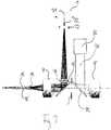
- Figure 1shows a light source unit according to the invention having a pump light source 1 for an emission of pump light 2.
- the pump light 2is guided to a phosphor element 3 for a conversion into converted light 4, wherein the converted light 4 is transmitted by an optical system 6 for a further use.
- the optical system 6is a telecentric optical system consisting of a first lens system 7 and an second lens system 8, such that rays 9 originating respectively from one point in an object plane are collimated in an aperture region 11 of the optical system 6 between the lens systems 7/8.
- the object planeis then imaged to an exit aperture 5 located subsequent to the second lens system 8.
- the telecentric optical system 6images an exit face 12, which is the above mentioned object plane, of a non-imaging optical element 13 collecting converted light from the phosphor element 3 and transmitting it to the telecentric optical system 6 by total internal reflection at its side walls 14.
- an air gapis provided between an entry face 15 of the non-imaging optical element 13 and the phosphor element 3 such that a refraction of converted light 4 towards the optical axis 10 results from the transition from air to the glass material of the non-imaging optical element 13.
- the pump light 2is, according to the invention, coupled to the optical system 6 by a dichroic mirror 16, which is provided within the optical system, and is transmitted (not shown in the figure) by the optical system 6, namely by the lens system 7, and the non-imaging optical element 13 to the phosphor element 3.
- the dichroic mirror 16is designed for reflecting the pump light 2 and is at the same time transmitting the converted light 4. Therefore, a system of multiple layers of dielectric material is provided, likewise having a wavelength dependant reflectivity and transmissivity due to interference effects further depending on the distance between the layers and their refractive index.
- the selectivity of the dichroic mirror 16is dependent of an angle of incidence, which alters the "effective" distance between the layers, losses due to an unintended reflection/transmission can be reduced by providing the dichroic mirror 16 in the aperture region 11, as the angular extent of a beam, namely a divergence of rays, is minimal there.
- the pump light 2is incident onto the phosphor element 3 in a main propagation direction 17 (axial to the left), and the phosphor element emits the converted light (to the right) into a hemisphere, such that an average value also gives a main propagation direction 18 of the converted light 4, which is opposite to the main propagation direction 17 of the pump light 2.
- the phosphor element 3is operated in reflection mode. Therefore, it can be provided on a heat sink 19, which is optimized with respect to transferring heat from the phosphor element.
- Figure 2shows a modification of figure 1 , wherein parts having the same functionality are referenced with identical numerals (as with all following figures).
- the pump light 2is coupled to the optical system 6 by a conventional mirror 21, which reflects the pump light 2 and the converted light 4 as well.
- the loss of converted light 5is moderate, as the size of the mirror 21, namely its projection into a plane being perpendicular to the optical axis 10, is small with respect to the cross-section of the aperture region or aperture plane of the optical system 6.
- partially shadowing the converted light 4 by the mirror 21does slightly reduce the brightness of the converted light 4 at the exit aperture 5, but does not cut a specific part from the image.
- the embodiment shown in figure 3comprises a telecentric optical system consisting of the lens systems 7/8 and a non-imaging optical element 13 as explained with reference to figure 1 .
- the pump light source 1is a single laser device 31 here, where a laser array can be provided likewise.
- the laser beam 32is defocused by a lens system 33, such that it is coupled to the optical system 6 with a slightly diverging angular extent. In this way, the cross-section of the beam 32 is smaller than an image 34 of the aperture 5, as the angular extent of the laser beam 32 is smaller than the aperture angle of the optical system 6.
- the focus 35 of the lens 8is shifted from the entry face 12 of the non-imaging optical element 13 (which is identical to the exit face 12 for the converted light) into the non-imaging optical element 13. Shifting the focus 35 from the entry face 12 prevents a hot spot formation on it, such that a burning of residuals on the surface can be avoided.
- the pump lightis more efficiently mixed within the non-imaging element 13 and illuminates the phosphor element homogeneously.
- an additional light source 36is provided, which emits light 37 having a spectral distribution being different from the spectral distribution of the converted light 4.
- the converted light 4is not drawn in the picture for the sake of clarity, but propagates from the left to the right as shown in figure 2 .
- a second dichroic mirror 38which is transmissive for the converted light 4 but reflective for the additional light 37.
- the additional light 37is superimposed with the converted light 4 by the dichroic mirror 38 and exits the optical system 6 through the lens system 8.
- Figure 4shows a setup with three pump light sources 1a/1b/1c, each providing pump light 2a/2b/2c for one phosphor element 3a/3b/3c, respectively.
- the phosphor elements 3a/3b/3care designed to emit converted light 4a/4b/4c in the red (c), the green (b), and the blue (a) spectral range, such that white light can be provided and a colour mixing is possible, respectively, by superimposing the converted light 4a/4b/4c.
- a first dichroic mirror 16ais adapted for a reflection of the ultraviolet pump light 2a (pumping blue phosphor) and a transmission of the blue converted light 4a.
- the blue converted light 4ais then reflected by another dichroic mirror 16c to the lens system 8, which also collects the other converted light beams 4b/4c.
- the dichroic mirror 16cfurther reflects the pump light 2c (pumping red phosphor) to a third dichroic mirror 16b, which is reflective for the pump light 2c as well as for the red converted light 4c. Therefore, the pump light 2c is guided to the red phosphor element 3c, and the red converted light 4c is reflected by the dichroic mirror 16b.
- the dichroic mirror 16breflects pump light 2b (pumping green phosphor), but transmits green converted light 3b.
- the green converted light 3bis superimposed with the red converted light 4c at the dichroic mirror 16b and then, as the dichroic mirror 16c is transmissive for red and green converted light 3b/4c, all three colours are superimposed at the dichroic mirror 16c and are simultaneously transmitted to the exit aperture 5 of the combined light source units.
- Figure 5shows an imaging optical element, which is the "left"/primary part of an optical system 6, for collecting the light from the phosphor element 3. Therefore a lens system 7 consisting of two lens elements 52/53 is provided. With this setup, the light coming from any individual point of the phosphor elements surface is spread over the whole aperture plane 54.
- the setupcorresponds to those shown in Figures 1 and 2 , besides providing no non-imaging optical element 13 between the optical system 6 and the phosphor element 3.
- Figure 6shows a combination of a mask 61 and a lens system 51.
- the mask 61is a gobo (graphical optical blackout) being placed in the aperture plane 54 of the lens system 51, such that it is illuminated by the converted light 4.
- the pump light 2is coupled to the optical system 6 in a peripheral region outside the gobo area, such that it basically bypasses the gobo 61 and is not blocked by its pattern.
- the peripheral coupling of pump light 2can for example be provided as shown in figure 2 .
- a projection lens(not shown) can be provided to image the gobo to a screen.
Landscapes
- Engineering & Computer Science (AREA)
- Physics & Mathematics (AREA)
- General Engineering & Computer Science (AREA)
- Spectroscopy & Molecular Physics (AREA)
- General Physics & Mathematics (AREA)
- Multimedia (AREA)
- Signal Processing (AREA)
- Projection Apparatus (AREA)
- Lenses (AREA)
Description
- This invention relates to a light source unit comprising a pump light source for an emission of pump light and a phosphor element for a conversion of the pump light into converted light.
- There is an increasing need for high luminance light sources in applications from projection systems and high speed industrial inspection to optical fibre-coupled illumination in surgical endoscopy. Therein, bright discharge lamps are the state of the art being broadly used today. Recent developments are heading for a combination of solid-state light sources, in particular light emitting diodes (LED), and light converting phosphor elements. Therein, the typically blue or ultraviolet solid-state based light is converted to light having less energy and a longer wave length by a transmission through the phosphor element.
- The problem that the invention is to solve, is to provide an improved light source unit having a pump light source and a phosphor element.
WO 2006/124993 A1 describes an illumination source according to the prior art including a number of light emitting diodes and a phosphor material. - This problem is solved with a light source unit, which is, besides the pump light source and the phosphor element, further comprising an optical system for transmitting at least a part of the converted light for further use, wherein at least a part of the pump light is coupled into this optical system and transmitted by the optical system to the phosphor element for the conversion.
- Hence, the optical system is, on the one hand, transmitting converted light for the further use, for example by bridging a spatial distance between the phosphor element and by adjusting the cross-section of a beam or its angular extent. On the other hand, the optical system is, according to this invention, also used for transmitting pump light to the phosphor element, thus having a double function advantageously.
- This integration of functions allows a reduction of the space required for the light source unit, which for example can simplify the handling of the light source unit during production and also reduce cost for transport and storage. Further, a size reduction is particularly desirable with respect to a final product, for example in consumer applications as projection systems.
- The optical system can, as mentioned above, have a varying function with respect to the further use. It can be an imaging optical system including imaging optical elements, as for example lenses, however, the optical system can also comprise non-imaging optical elements, such as compound concentrators or light guides.
- The phosphor element converts the pump light by an absorption of the pump light and an emission of light having a lower energy and a longer wave length, wherein a spontaneous emission, not a stimulated emission, is dominant. A phosphor type illustrating, but not limiting the present invention is Ce or Eu doped YAG (Yttrium Aluminum Garnet).
- The optical system transmits the converted light from the phosphor element preferably to an exit aperture of the light source unit, which can for instance serve as an imager of a projection system or as an input of an optical fibre. Therein, according to one embodiment, the optical system can provide an image of a part of the phosphor element or of the element as a whole to the exit aperture, or it can, according to another embodiment, also provide an image of a surface of an additional non-imaging optical element, which collects light from the phosphor element, to the exit aperture.
- Preferred embodiments appear from the depending claims and the following description, wherein the details refer to all aspects of the invention and are meant as being disclosed individually. Further, the invention is not restricted to the apparatus category, but also disclosed in terms of methods applying the features disclosed herein or a use of respective light source units or lighting systems.
- According to the invention, the optical system of the light source unit is at least one-sided telecentric. Preferably, it is telecentric on two sides, an object and an image side. In this way, a high transmission efficiency for light beams being symmetrical with respect to the optical axis can be ensured, such that the transmission of converted or pump light can be optimized. According to the invention the telecentric optical system comprises two lenses and has an aperture plane between these lenses, wherein the pump light is coupled into the optical system in a region between the lenses, which is referred to as "aperture region". A lens can be a single lens element, namely one individual lens, or also a lens system comprising two or more lens elements. Coupling the pump light into the aperture region can be advantageous, as the pump light can, depending on its angular extent, preferably be homogenized for a uniform illumination of the phosphor element.
- The aperture plane is, in this context, not necessarily physically limiting the cross-section of a beam, as in case of an aperture stop or diaphragm, but is a region within the telecentric optical system, in which parallel rays from the object are focused and rays emerging from an object point are collimated.
- Another preferred embodiment relates to a light source unit with the optical system having an aperture plane and being symmetrical with respect to the aperture plane.
- In the context of this invention, the cross-section of the optical system in an area perpendicular to a main propagation direction of the light, in particular of its aperture plane, will be large with respect to the phosphor area, preferably larger than a projection of the phosphor element into the same area, to maximize the amount of light collected. As a consequence of conservation laws, the angular extent of the light (in the following referred to as the "aperture angle") is much smaller in the aperture plane or in the aperture region than its original emission angle at the phosphor element.
- A coupling of the pump light into the optical system in the aperture region is advantageous, as any shadowing in the aperture region does not cut a specific part from the image but, instead, homogeneously reduces the brightness in an exit aperture.
- Coupling the pump light into the aperture region of the optical system is therefore particularly advantageous in combination with another preferred embodiment, according to which the optical system comprises a mirror, wherein the pump light is coupled to the mirror within the optical system.
- The mirror is preferably provided in the aperture region of the optical system and reflects at least a part of the pump light towards the phosphor element via a part of the optical system. In this context, even a mirror reflecting not only the pump light but also the converted light can be provided between the lenses, as a sufficiently small mirror will only slightly reduce the brightness of the converted light transmitted by the optical system, for example to an exit aperture.
- Furthermore, the coupling of pump light into the optical system can also be realized with a dichroic mirror, which for example reflects pump light and transmits converted light. It is advantageous to provide the dichroic mirror in the aperture region, as the above mentioned aperture angle is a minimum of the angular extent of the converted light. Further, the performance of a dichroic mirror can depend on an angle of incidence, such that a good performance can be obtained for the small angular extent of the angles of incidence in the aperture region.
- A preferred embodiment thus relates to a coupling by a dichroic mirror, which can for example be an interference mirror having a layer system.
- In one embodiment, the invention relates to using the imaging optical system directly for collecting the converted light, thus imaging the phosphor element, for example to an exit aperture of the light source unit.
- According to a different embodiment of the invention, a non-imaging optical element is provided between the phosphor element and the optical system, such that the optical system being an imaging one images an exit face of the non-imaging optical element, preferably to an exit aperture of the light source unit. The non-imaging optical element is provided for collecting light from the phosphor element and transmitting it to the optical system. It can be designed for example as a hollow light pipe having a reflective coating at its inner surfaces or as a dielectric light guide, which guides the light by total internal reflection within a core having a higher refractive index than a cladding or a surrounding medium, for example as surrounding air.
- The tube or guide can preferably have an elongated shape with respect to the propagation direction of the light and can further have a circular or rectangular cross-section in an area perpendicular to this propagation direction. Further, the guide or tube can have a funnel-like shape with a entry face being located at the phosphor element and an exit face larger than the entry face being imaged by the optical system, for example to its exit aperture. A combination of the funnel-like shape and the rectangular cross-section will result in a trapezoidal cross-section in an area comprising the main propagation direction. In comparison to providing only an imaging optical system, collecting light from the phosphor element can be improved by additionally using a non-imaging optical element, as imaging systems with acceptance angles close to 90° (the phosphor is a Lambertian emitter) are hard to realize or inefficient.
- In this context, it is further preferred that an air gap is provided between an entry face of a dielectric non-imaging optical element and the phosphor element. The transition from air having a refractive index around 1 to the dichroic non-imaging optical element, for example a glass material, having a refractive index above 1, preferably above 1.4, leads to a refraction of the converted light towards a normal on the entry face, thus towards the main propagation direction in the tube or guide. Hence, light can be collected more efficiently by the non-imaging optical element.
- Providing a non imaging optical element is further advantageous, as it enables a completely symmetrical telecentric optical system, which provides an image of the exit face of the non-imaging element to an exit aperture of the light source unit with a unitary magnification. In this way, aberrations, as for example a distortion and a lateral color, can be avoided, thus ensuring a highly efficient transmission of light.
- Preferably, the pumping light is incident in a main propagation direction onto the phosphor element with this main propagation direction being opposite to a main propagation direction of the converted light. Thus, the phosphor element is operated in reflection mode, wherein a deviation from 180° of +/- 45° is also considered as "opposite direction". Therein, the main propagation direction can, for example in case of a diverging or converging beam, be a mean or average direction of propagation (this refers to the disclosure as a whole).
- Therefore, the phosphor element can, according to another preferred embodiment, be provided on a heat sink being not translucent for the pump light. The heat sink transfers heat, which can be generated within the phosphor element for example due to the Stokes shift during the conversion, away from the phosphor element. Therefore, a material having a good thermal conductivity is preferably provided for the heat sink, for example a metal, e.g. copper, aluminum, or alloys thereof. Further, the heat sink is preferred to have a large surface for a transmission of heat to a surrounding medium, for example to surrounding air, such that also cooling fins can be provided. In this respect, the operation of the phosphor element in reflection mode allows a straightforward heat sink design.
- A further aspect of the invention relates to the coupling of the pump light, which is, with the optical system having an optical axis and an aperture angle, preferably coupled to the optical axis such that its maximum angle to the optical axis is after the coupling equal to or less than the aperture angle of the system, which is an optical design dependent value therein, the "maximum angle to the optical axis" is the angular extend of the pump light beam. In combination with the cross-section of the pump light beam being preferably equal to or smaller than the cross-section of the aperture region in an area perpendicular to a main propagation direction, the angular extent of the beam being smaller than or equal to an aperture angle of the optical system can for example ensure that only those phosphor positions are excited, from which the converted light can then be transmitted by the optical system.
- Reflecting a highly collimated pump light, which can for example be provided by a LASER, into the optical system by the aforementioned mirror could disadvantageously lead to concentrated pump light spots on the phosphor element or on a entry face (exit face for the converted light) of a non-imaging optical element. Therefore, it is preferred to slightly defocus any highly collimated pump light while keeping the resulting angular extent smaller than the aperture angle of the optical system. In case of a non-imaging optical element between the phosphor element and the optical system, the inventors found that it is advantageous to provide pump light entering the aperture region of the optical system slightly divergent. In this way, the focus can be shifted from the phosphor element or the entry face towards an inner region. In this way, a mixing of the pump light in the non-imaging optical element becomes surprisingly much more effective, which results in a homogeneous distribution of the pump light on the phosphor element.
- According to a preferred embodiment, the converted light has a first spectral distribution and an additional light source is provided, which emits additional light with a second spectral distribution, wherein the additional light is coupled to the optical system for a superposition with the converted light. The second spectral distribution can supplement the first spectral distribution, for example by adding individual lines or even spectral ranges. Thus, the resulting spectrum can for example be more evenly distributed, if a spectral minimum is filled, or have a broader distribution, if a spectral region is added. In this way, the converted light can be adapted to the specific requirements of an application.
- One embodiment of the invention provides a Light Emitting Diode (LED)- or a Light Amplification by Stimulated Emission of Radiation (LASER)-device as pump light source. The pump light source can also be an array of individual LASER or LED devices, respectively, to provide a required amount of pump light power.
- In one embodiment of the invention, the optical system has an aperture plane, in which a mask is provided. Those features, which are additionally introduced by
claim 12, are considered as an invention also independent ofclaim 1 and shall be disclosed in such a way. As a matter of course, also any combinations ofclaim 12 with other features disclosed in this application are possible. - Namely, the optical system preferably comprises a lens (lens element or lens system) defining the aperture plane, which has a certain distance (aperture distance) to the lens. In this context, the mask does not have to be provided exactly in the aperture plane, but can also be provided within the aperture distance to it (in both directions along an optical axis). The mask can for example be a graphical optical blackout (gobo) and is preferably covering an inner portion of the aperture plane. In this embodiment, the pump light can for example be coupled into the optical system and be transmitted towards the phosphor element by one single small mirror or by several small mirrors being located outside of the gobo area in the aperture region. In this way, the mask or gobo is illuminated by converted light being transmitted from the phosphor element, wherein a secondary part of the optical system then acts as a projection lens.
- A further aspect of the invention relates to a lighting system comprising at least two light source units as described above and a mirror for at least partially reflecting converted light, wherein converted light is superimposed by the mirror element. Thus, converted light having identical spectral properties can be superimposed for increasing the luminance. Likewise, also converted light, which differs in its spectral distribution, can be superimposed for a supplementation of the resulting spectrum.
- It is also possible to superimpose light of three different phosphor types, for instance emitting in a red, green, and blue spectral range, wherein controlling, also feedback-controlling, the individual sources allows adjusting the resulting color. Therein, a source can be controlled by the pump light, for example by controlling a power supply, or by an optical switching element, for example to operate the light source units in a time-sequential way.
- Further, the above mentioned dichroic mirror can be a cube with inner reflective planes (x cube) or a prism with inner reflective planes.
- For a superposition of converted light from individual light source units being for example geometrically identical, it can be advantageous to design the optical system such that the respective aperture regions are large enough for receiving two dichroic mirrors. In this way, one mirror can be used for coupling the pump light into the respective optical system and the other mirror can be used for combining different beams of converted light. As a result, a secondary part of the optical system, being for example provided between the aperture plane and an exit aperture, can preferably be provided only once and transmits the combined beams to an exit aperture of the lighting system.
- Therefore, the invention also relates to a lighting system comprising at least two light source units or an aforementioned lighting system with the optical systems of the light source units being telecentric optical systems, wherein one lens, which can be again a single lens element or a lens system, is shared by the optical systems and transmits the light, for example to an exit aperture of the lighting system. Of course, also three light sources units comprising three different phosphor types can likewise share this secondary part of the optical system, such that the aforementioned colour mixing is possible.
- The invention also relates to using a light source unit, or a lighting system, or both for a fibre-optical illumination, for example in endoscopy applications, or for an application in a projection system.
- Fig. 1
- illustrates a light source unit as a first embodiment having a telecentric optical system and a dichroic mirror.
- Fig. 2
- shows a light source unit having a telecentric optical system and a small conventional mirror as a second embodiment.
- Fig. 3
- shows a light source unit being pumped by laser light as a third embodiment.
- Fig. 4
- illustrates a combination of three light source units as a fourth embodiment.
- Fig. 5
- shows an imaging optical system imaging a phosphor element as a fifth embodiment.
- Fig. 6
- shows a combination of an imaging optical system and a mask (gobo) as a sixth embodiment.
Figure 1 shows a light source unit according to the invention having a pumplight source 1 for an emission ofpump light 2. Thepump light 2 is guided to aphosphor element 3 for a conversion into convertedlight 4, wherein the convertedlight 4 is transmitted by anoptical system 6 for a further use. Theoptical system 6 is a telecentric optical system consisting of afirst lens system 7 and ansecond lens system 8, such that rays 9 originating respectively from one point in an object plane are collimated in an aperture region 11 of theoptical system 6 between thelens systems 7/8. The object plane is then imaged to anexit aperture 5 located subsequent to thesecond lens system 8.- In this way, the telecentric
optical system 6 images anexit face 12, which is the above mentioned object plane, of a non-imagingoptical element 13 collecting converted light from thephosphor element 3 and transmitting it to the telecentricoptical system 6 by total internal reflection at itsside walls 14. Therein, an air gap is provided between anentry face 15 of the non-imagingoptical element 13 and thephosphor element 3 such that a refraction of converted light 4 towards the optical axis 10 results from the transition from air to the glass material of the non-imagingoptical element 13. - The
pump light 2 is, according to the invention, coupled to theoptical system 6 by adichroic mirror 16, which is provided within the optical system, and is transmitted (not shown in the figure) by theoptical system 6, namely by thelens system 7, and the non-imagingoptical element 13 to thephosphor element 3. Thedichroic mirror 16 is designed for reflecting thepump light 2 and is at the same time transmitting the convertedlight 4. Therefore, a system of multiple layers of dielectric material is provided, likewise having a wavelength dependant reflectivity and transmissivity due to interference effects further depending on the distance between the layers and their refractive index. Since the selectivity of thedichroic mirror 16 is dependent of an angle of incidence, which alters the "effective" distance between the layers, losses due to an unintended reflection/transmission can be reduced by providing thedichroic mirror 16 in the aperture region 11, as the angular extent of a beam, namely a divergence of rays, is minimal there. - The
pump light 2 is incident onto thephosphor element 3 in a main propagation direction 17 (axial to the left), and the phosphor element emits the converted light (to the right) into a hemisphere, such that an average value also gives a main propagation direction 18 of the convertedlight 4, which is opposite to themain propagation direction 17 of thepump light 2. Thus, thephosphor element 3 is operated in reflection mode. Therefore, it can be provided on aheat sink 19, which is optimized with respect to transferring heat from the phosphor element. Figure 2 shows a modification offigure 1 , wherein parts having the same functionality are referenced with identical numerals (as with all following figures). In this embodiment, thepump light 2 is coupled to theoptical system 6 by aconventional mirror 21, which reflects thepump light 2 and the convertedlight 4 as well. However, the loss of convertedlight 5 is moderate, as the size of themirror 21, namely its projection into a plane being perpendicular to the optical axis 10, is small with respect to the cross-section of the aperture region or aperture plane of theoptical system 6. Thus, partially shadowing the convertedlight 4 by themirror 21 does slightly reduce the brightness of the convertedlight 4 at theexit aperture 5, but does not cut a specific part from the image.- The embodiment shown in
figure 3 comprises a telecentric optical system consisting of thelens systems 7/8 and a non-imagingoptical element 13 as explained with reference tofigure 1 . Further, the pumplight source 1 is a single laser device 31 here, where a laser array can be provided likewise. Thelaser beam 32 is defocused by alens system 33, such that it is coupled to theoptical system 6 with a slightly diverging angular extent. In this way, the cross-section of thebeam 32 is smaller than animage 34 of theaperture 5, as the angular extent of thelaser beam 32 is smaller than the aperture angle of theoptical system 6. Thus, thefocus 35 of thelens 8 is shifted from theentry face 12 of the non-imaging optical element 13 (which is identical to theexit face 12 for the converted light) into the non-imagingoptical element 13. Shifting thefocus 35 from theentry face 12 prevents a hot spot formation on it, such that a burning of residuals on the surface can be avoided. In addition, the pump light is more efficiently mixed within thenon-imaging element 13 and illuminates the phosphor element homogeneously. - Further, an additional
light source 36 is provided, which emits light 37 having a spectral distribution being different from the spectral distribution of the convertedlight 4. The convertedlight 4 is not drawn in the picture for the sake of clarity, but propagates from the left to the right as shown infigure 2 . Therein, it passes a seconddichroic mirror 38, which is transmissive for the convertedlight 4 but reflective for theadditional light 37. In this way, theadditional light 37 is superimposed with the convertedlight 4 by thedichroic mirror 38 and exits theoptical system 6 through thelens system 8. Figure 4 shows a setup with three pump light sources 1a/1b/1c, each providingpump light 2a/2b/2c for one phosphor element 3a/3b/3c, respectively. Therein, the phosphor elements 3a/3b/3c are designed to emit converted light 4a/4b/4c in the red (c), the green (b), and the blue (a) spectral range, such that white light can be provided and a colour mixing is possible, respectively, by superimposing the converted light 4a/4b/4c.- Therein, a first dichroic mirror 16a is adapted for a reflection of the
ultraviolet pump light 2a (pumping blue phosphor) and a transmission of the blue converted light 4a. The blue converted light 4a is then reflected by anotherdichroic mirror 16c to thelens system 8, which also collects the other converted light beams 4b/4c. Thedichroic mirror 16c further reflects the pump light 2c (pumping red phosphor) to a third dichroic mirror 16b, which is reflective for the pump light 2c as well as for the red converted light 4c. Therefore, the pump light 2c is guided to the red phosphor element 3c, and the red converted light 4c is reflected by the dichroic mirror 16b. It is then transmitted by thedichroic mirror 16c and collected by thelens system 8 as well. Further, the dichroic mirror 16b reflects pump light 2b (pumping green phosphor), but transmits green converted light 3b. The green converted light 3b is superimposed with the red converted light 4c at the dichroic mirror 16b and then, as thedichroic mirror 16c is transmissive for red and green converted light 3b/4c, all three colours are superimposed at thedichroic mirror 16c and are simultaneously transmitted to theexit aperture 5 of the combined light source units. Figure 5 shows an imaging optical element, which is the "left"/primary part of anoptical system 6, for collecting the light from thephosphor element 3. Therefore alens system 7 consisting of twolens elements 52/53 is provided. With this setup, the light coming from any individual point of the phosphor elements surface is spread over thewhole aperture plane 54. The setup corresponds to those shown inFigures 1 and2 , besides providing no non-imagingoptical element 13 between theoptical system 6 and thephosphor element 3.Figure 6 shows a combination of amask 61 and alens system 51. Themask 61 is a gobo (graphical optical blackout) being placed in theaperture plane 54 of thelens system 51, such that it is illuminated by the convertedlight 4. With this embodiment, thepump light 2 is coupled to theoptical system 6 in a peripheral region outside the gobo area, such that it basically bypasses thegobo 61 and is not blocked by its pattern. The peripheral coupling ofpump light 2 can for example be provided as shown infigure 2 . Further, a projection lens (not shown) can be provided to image the gobo to a screen.
Claims (13)
- A light source unit comprising:a pump light source (1) for an emission of pump light (2),a phosphor element (3) for a conversion of said pump light (2) into converted light (4),an optical system (6) for transmitting at least a part of said converted light (4) for further use,wherein at least a part of said pump light (2) is coupled into said optical system (6) and transmitted by said optical system (6) to said phosphor element (3) for said conversion, wherein said optical system (6) is at least one-sided telecentric,characterised in that said telecentric optical system (6) comprises two lenses (7, 8) and has an aperture plane (5) between said lenses (7, 8), wherein said pump light (2) is coupled to said optical system (6) between said lenses (7, 8).
- The light source unit according to claim 1, wherein said optical system (6) has an aperture plane (5) and is symmetrical with respect to said aperture plane (5).
- The light source unit according to one of the preceding claims, wherein said optical system (6) comprises a mirror (16, 21), preferably a dichroic mirror, and said pump light (2) is coupled to said mirror (16, 21) within said optical system (6).
- The light source unit according to one of the preceding claims with said optical system (6) being an imaging optical system (6), wherein a non-imaging optical element (13) is provided between said phosphor element (3) and said imaging optical system (6) for collecting said converted light (4), wherein said imaging optical system (6) images an exit face (12) of said non-imaging optical element (13).
- The light source unit according to claim 4 with said non-imaging optical element (13) being designed of a translucent dielectric medium, wherein an air gap is provided between an entry face (15) of said non-imaging optical element (13) and said phosphor element (3).
- The light source unit according to one of the preceding claims with said pump light (2) being incident in a main propagation direction (17) onto said phosphor element (3) and with said converted light (4) having a main propagation direction (18) at said phosphor element (3), wherein said two propagation directions (17, 18) are opposite to each other.
- The light source unit according to one of the preceding claims, wherein said phosphor element (3) is provided on a heat sink (19) being not translucent for said pump light (2).
- The light source unit according to one of the preceding claims with said optical system (6) having an optical axis and an aperture angle, wherein said pump light (2) has a maximum angle to said optical axis (10) after said coupling, which maximum angle is less than said aperture angle of said optical system (6).
- The light source unit according to one of the preceding claims with said converted light (4) having a first spectral distribution, wherein an additional light source (36) is provided, said additional light source (36) emitting additional light (37) with a second spectral distribution being different from said first spectral distribution, wherein said additional light (37) is coupled to said optical system (6) for superimposing said additional light (37) with said converted light (4).
- The light source unit according to one of the preceding claims with said optical system (6, 51) having an aperture plane (5), wherein a mask (61) is provided in said aperture plane (5) of said optical system (6, 51).
- A lighting system comprising at least two light source units according to one of the preceding claims and a mirror element (16a, 16b, 16c) for at least partially reflecting converted light (4a, 4b, 4c), wherein converted light (4a, 4b, 4c) is superimposed by said mirror element (16a, 16b, 16c).
- A lighting system comprising at least two light source units according to one of claims 1 to 10 or comprising a lighting system according to claim 11, wherein said optical systems (6a, 6b, 6c) of said light source units are telecentric optical systems (6a, 6b, 6c) with said telecentric optical systems (6a, 6b, 6c) each having two lenses (7a, 7b, 7c, 8a, 8b, 8c), wherein one lens (8a, 8b, 8c) is shared by said telecentric optical systems (6a, 6b, 6c).
- A use of a light source unit according to one of claims 1 to 10 or of a lighting system according to claim 11 or 12 for a fibre-optical illumination or an application in a projection system.
Applications Claiming Priority (1)
| Application Number | Priority Date | Filing Date | Title |
|---|---|---|---|
| PCT/EP2010/058998WO2011160693A1 (en) | 2010-06-24 | 2010-06-24 | Light source unit with phosphor element |
Publications (2)
| Publication Number | Publication Date |
|---|---|
| EP2526336A1 EP2526336A1 (en) | 2012-11-28 |
| EP2526336B1true EP2526336B1 (en) | 2018-03-07 |
Family
ID=43733978
Family Applications (1)
| Application Number | Title | Priority Date | Filing Date |
|---|---|---|---|
| EP10732330.5AActiveEP2526336B1 (en) | 2010-06-24 | 2010-06-24 | Light source unit with phosphor element |
Country Status (4)
| Country | Link |
|---|---|
| US (1) | US9121578B2 (en) |
| EP (1) | EP2526336B1 (en) |
| CN (1) | CN102971581B (en) |
| WO (1) | WO2011160693A1 (en) |
Families Citing this family (4)
| Publication number | Priority date | Publication date | Assignee | Title |
|---|---|---|---|---|
| US20130329448A1 (en)* | 2011-03-01 | 2013-12-12 | Osram Gmbh | Lighting apparatus with phosphor element |
| US9599316B2 (en)* | 2012-09-10 | 2017-03-21 | Mitsubishi Electric Corporation | Light source device using monochromatic light to excite stationary phosphor layers |
| JP6271216B2 (en)* | 2013-10-29 | 2018-01-31 | シャープ株式会社 | Light emitting unit and lighting device |
| CN106523955B (en) | 2015-09-14 | 2019-10-11 | 中强光电股份有限公司 | Illumination system and projection device |
Family Cites Families (6)
| Publication number | Priority date | Publication date | Assignee | Title |
|---|---|---|---|---|
| MXPA05005802A (en)* | 2002-12-04 | 2005-08-16 | Thomson Licensing Sa | Imager to imager relay lens system. |
| US7070300B2 (en)* | 2004-06-04 | 2006-07-04 | Philips Lumileds Lighting Company, Llc | Remote wavelength conversion in an illumination device |
| US7234820B2 (en) | 2005-04-11 | 2007-06-26 | Philips Lumileds Lighting Company, Llc | Illuminators using reflective optics with recycling and color mixing |
| US7445340B2 (en)* | 2005-05-19 | 2008-11-04 | 3M Innovative Properties Company | Polarized, LED-based illumination source |
| US7665858B2 (en)* | 2007-11-02 | 2010-02-23 | Waqidi Falicoff | Optical manifold |
| CN101231378B (en)* | 2007-12-21 | 2010-11-10 | 上海微电子装备有限公司 | Complete refraction type projection optical system |
- 2010
- 2010-06-24CNCN201080067693.6Apatent/CN102971581B/enactiveActive
- 2010-06-24USUS13/805,990patent/US9121578B2/enactiveActive
- 2010-06-24WOPCT/EP2010/058998patent/WO2011160693A1/enactiveApplication Filing
- 2010-06-24EPEP10732330.5Apatent/EP2526336B1/enactiveActive
Also Published As
| Publication number | Publication date |
|---|---|
| US20130094182A1 (en) | 2013-04-18 |
| EP2526336A1 (en) | 2012-11-28 |
| CN102971581B (en) | 2017-03-22 |
| US9121578B2 (en) | 2015-09-01 |
| WO2011160693A1 (en) | 2011-12-29 |
| CN102971581A (en) | 2013-03-13 |
Similar Documents
| Publication | Publication Date | Title |
|---|---|---|
| US9115862B2 (en) | Colour-tunable light source unit with phosphor element | |
| KR101425901B1 (en) | Light source unit and projector having such a light source unit | |
| US8629982B2 (en) | Light emitting diode illumination system | |
| CN102549492B (en) | Light source device and projection display device using same | |
| US7744241B2 (en) | High brightness light source using light emitting devices of different wavelengths and wavelength conversion | |
| CN103615671B (en) | Light source | |
| JP2009529220A (en) | Light emitting diode projection system | |
| JP7123231B2 (en) | Light source device | |
| US20120217519A1 (en) | Method and structure for encapsulating solid-state light emitting chip and light sources using the encapsulation structure | |
| US20130329448A1 (en) | Lighting apparatus with phosphor element | |
| CN106842789A (en) | Light source optical system and projection display device using light source optical system | |
| WO2014073136A1 (en) | Light source and image projection apparatus | |
| JP6804448B2 (en) | Luminescent device | |
| KR20020040861A (en) | Lamp apparatus and method for effectively utilizing light from an aperture lamp | |
| CN111856860B (en) | Light source system and display device | |
| JP2008219015A (en) | Optical device and optical method | |
| KR20100053638A (en) | Lighting device | |
| EP2526336B1 (en) | Light source unit with phosphor element | |
| JP5711246B2 (en) | Lighting device | |
| CN211780878U (en) | Hybrid light emitting device | |
| CA3200809A1 (en) | Light source | |
| Hartwig | Fiber optic illumination by laser activated remote phosphor | |
| CN109424943B (en) | Wavelength Conversion Device and Laser Fluorescence Conversion Light Source | |
| WO2024065695A1 (en) | Polarization light source apparatus | |
| CN113900333B (en) | Light source assembly and projection equipment |
Legal Events
| Date | Code | Title | Description |
|---|---|---|---|
| PUAI | Public reference made under article 153(3) epc to a published international application that has entered the european phase | Free format text:ORIGINAL CODE: 0009012 | |
| 17P | Request for examination filed | Effective date:20120727 | |
| AK | Designated contracting states | Kind code of ref document:A1 Designated state(s):AL AT BE BG CH CY CZ DE DK EE ES FI FR GB GR HR HU IE IS IT LI LT LU LV MC MK MT NL NO PL PT RO SE SI SK SM TR | |
| RAP1 | Party data changed (applicant data changed or rights of an application transferred) | Owner name:OSRAM GMBH | |
| RAP1 | Party data changed (applicant data changed or rights of an application transferred) | Owner name:OSRAM GMBH | |
| DAX | Request for extension of the european patent (deleted) | ||
| GRAP | Despatch of communication of intention to grant a patent | Free format text:ORIGINAL CODE: EPIDOSNIGR1 | |
| INTG | Intention to grant announced | Effective date:20171009 | |
| GRAS | Grant fee paid | Free format text:ORIGINAL CODE: EPIDOSNIGR3 | |
| GRAA | (expected) grant | Free format text:ORIGINAL CODE: 0009210 | |
| AK | Designated contracting states | Kind code of ref document:B1 Designated state(s):AL AT BE BG CH CY CZ DE DK EE ES FI FR GB GR HR HU IE IS IT LI LT LU LV MC MK MT NL NO PL PT RO SE SI SK SM TR | |
| REG | Reference to a national code | Ref country code:GB Ref legal event code:FG4D | |
| REG | Reference to a national code | Ref country code:CH Ref legal event code:EP Ref country code:AT Ref legal event code:REF Ref document number:976944 Country of ref document:AT Kind code of ref document:T Effective date:20180315 | |
| REG | Reference to a national code | Ref country code:IE Ref legal event code:FG4D | |
| REG | Reference to a national code | Ref country code:DE Ref legal event code:R096 Ref document number:602010049011 Country of ref document:DE | |
| REG | Reference to a national code | Ref country code:NL Ref legal event code:MP Effective date:20180307 | |
| REG | Reference to a national code | Ref country code:LT Ref legal event code:MG4D | |
| PG25 | Lapsed in a contracting state [announced via postgrant information from national office to epo] | Ref country code:ES Free format text:LAPSE BECAUSE OF FAILURE TO SUBMIT A TRANSLATION OF THE DESCRIPTION OR TO PAY THE FEE WITHIN THE PRESCRIBED TIME-LIMIT Effective date:20180307 Ref country code:LT Free format text:LAPSE BECAUSE OF FAILURE TO SUBMIT A TRANSLATION OF THE DESCRIPTION OR TO PAY THE FEE WITHIN THE PRESCRIBED TIME-LIMIT Effective date:20180307 Ref country code:HR Free format text:LAPSE BECAUSE OF FAILURE TO SUBMIT A TRANSLATION OF THE DESCRIPTION OR TO PAY THE FEE WITHIN THE PRESCRIBED TIME-LIMIT Effective date:20180307 Ref country code:CY Free format text:LAPSE BECAUSE OF FAILURE TO SUBMIT A TRANSLATION OF THE DESCRIPTION OR TO PAY THE FEE WITHIN THE PRESCRIBED TIME-LIMIT Effective date:20180307 Ref country code:FI Free format text:LAPSE BECAUSE OF FAILURE TO SUBMIT A TRANSLATION OF THE DESCRIPTION OR TO PAY THE FEE WITHIN THE PRESCRIBED TIME-LIMIT Effective date:20180307 Ref country code:NO Free format text:LAPSE BECAUSE OF FAILURE TO SUBMIT A TRANSLATION OF THE DESCRIPTION OR TO PAY THE FEE WITHIN THE PRESCRIBED TIME-LIMIT Effective date:20180607 | |
| REG | Reference to a national code | Ref country code:AT Ref legal event code:MK05 Ref document number:976944 Country of ref document:AT Kind code of ref document:T Effective date:20180307 | |
| PG25 | Lapsed in a contracting state [announced via postgrant information from national office to epo] | Ref country code:BG Free format text:LAPSE BECAUSE OF FAILURE TO SUBMIT A TRANSLATION OF THE DESCRIPTION OR TO PAY THE FEE WITHIN THE PRESCRIBED TIME-LIMIT Effective date:20180607 Ref country code:GR Free format text:LAPSE BECAUSE OF FAILURE TO SUBMIT A TRANSLATION OF THE DESCRIPTION OR TO PAY THE FEE WITHIN THE PRESCRIBED TIME-LIMIT Effective date:20180608 Ref country code:LV Free format text:LAPSE BECAUSE OF FAILURE TO SUBMIT A TRANSLATION OF THE DESCRIPTION OR TO PAY THE FEE WITHIN THE PRESCRIBED TIME-LIMIT Effective date:20180307 Ref country code:SE Free format text:LAPSE BECAUSE OF FAILURE TO SUBMIT A TRANSLATION OF THE DESCRIPTION OR TO PAY THE FEE WITHIN THE PRESCRIBED TIME-LIMIT Effective date:20180307 | |
| PG25 | Lapsed in a contracting state [announced via postgrant information from national office to epo] | Ref country code:RO Free format text:LAPSE BECAUSE OF FAILURE TO SUBMIT A TRANSLATION OF THE DESCRIPTION OR TO PAY THE FEE WITHIN THE PRESCRIBED TIME-LIMIT Effective date:20180307 Ref country code:PL Free format text:LAPSE BECAUSE OF FAILURE TO SUBMIT A TRANSLATION OF THE DESCRIPTION OR TO PAY THE FEE WITHIN THE PRESCRIBED TIME-LIMIT Effective date:20180307 Ref country code:AL Free format text:LAPSE BECAUSE OF FAILURE TO SUBMIT A TRANSLATION OF THE DESCRIPTION OR TO PAY THE FEE WITHIN THE PRESCRIBED TIME-LIMIT Effective date:20180307 Ref country code:NL Free format text:LAPSE BECAUSE OF FAILURE TO SUBMIT A TRANSLATION OF THE DESCRIPTION OR TO PAY THE FEE WITHIN THE PRESCRIBED TIME-LIMIT Effective date:20180307 Ref country code:EE Free format text:LAPSE BECAUSE OF FAILURE TO SUBMIT A TRANSLATION OF THE DESCRIPTION OR TO PAY THE FEE WITHIN THE PRESCRIBED TIME-LIMIT Effective date:20180307 Ref country code:IT Free format text:LAPSE BECAUSE OF FAILURE TO SUBMIT A TRANSLATION OF THE DESCRIPTION OR TO PAY THE FEE WITHIN THE PRESCRIBED TIME-LIMIT Effective date:20180307 | |
| PG25 | Lapsed in a contracting state [announced via postgrant information from national office to epo] | Ref country code:SM Free format text:LAPSE BECAUSE OF FAILURE TO SUBMIT A TRANSLATION OF THE DESCRIPTION OR TO PAY THE FEE WITHIN THE PRESCRIBED TIME-LIMIT Effective date:20180307 Ref country code:AT Free format text:LAPSE BECAUSE OF FAILURE TO SUBMIT A TRANSLATION OF THE DESCRIPTION OR TO PAY THE FEE WITHIN THE PRESCRIBED TIME-LIMIT Effective date:20180307 Ref country code:SK Free format text:LAPSE BECAUSE OF FAILURE TO SUBMIT A TRANSLATION OF THE DESCRIPTION OR TO PAY THE FEE WITHIN THE PRESCRIBED TIME-LIMIT Effective date:20180307 Ref country code:CZ Free format text:LAPSE BECAUSE OF FAILURE TO SUBMIT A TRANSLATION OF THE DESCRIPTION OR TO PAY THE FEE WITHIN THE PRESCRIBED TIME-LIMIT Effective date:20180307 | |
| REG | Reference to a national code | Ref country code:DE Ref legal event code:R097 Ref document number:602010049011 Country of ref document:DE | |
| PG25 | Lapsed in a contracting state [announced via postgrant information from national office to epo] | Ref country code:PT Free format text:LAPSE BECAUSE OF FAILURE TO SUBMIT A TRANSLATION OF THE DESCRIPTION OR TO PAY THE FEE WITHIN THE PRESCRIBED TIME-LIMIT Effective date:20180709 | |
| PLBE | No opposition filed within time limit | Free format text:ORIGINAL CODE: 0009261 | |
| STAA | Information on the status of an ep patent application or granted ep patent | Free format text:STATUS: NO OPPOSITION FILED WITHIN TIME LIMIT | |
| PG25 | Lapsed in a contracting state [announced via postgrant information from national office to epo] | Ref country code:DK Free format text:LAPSE BECAUSE OF FAILURE TO SUBMIT A TRANSLATION OF THE DESCRIPTION OR TO PAY THE FEE WITHIN THE PRESCRIBED TIME-LIMIT Effective date:20180307 | |
| REG | Reference to a national code | Ref country code:CH Ref legal event code:PL | |
| 26N | No opposition filed | Effective date:20181210 | |
| GBPC | Gb: european patent ceased through non-payment of renewal fee | Effective date:20180624 | |
| PG25 | Lapsed in a contracting state [announced via postgrant information from national office to epo] | Ref country code:SI Free format text:LAPSE BECAUSE OF FAILURE TO SUBMIT A TRANSLATION OF THE DESCRIPTION OR TO PAY THE FEE WITHIN THE PRESCRIBED TIME-LIMIT Effective date:20180307 | |
| REG | Reference to a national code | Ref country code:BE Ref legal event code:MM Effective date:20180630 | |
| REG | Reference to a national code | Ref country code:IE Ref legal event code:MM4A | |
| PG25 | Lapsed in a contracting state [announced via postgrant information from national office to epo] | Ref country code:LU Free format text:LAPSE BECAUSE OF NON-PAYMENT OF DUE FEES Effective date:20180624 Ref country code:MC Free format text:LAPSE BECAUSE OF FAILURE TO SUBMIT A TRANSLATION OF THE DESCRIPTION OR TO PAY THE FEE WITHIN THE PRESCRIBED TIME-LIMIT Effective date:20180307 | |
| PG25 | Lapsed in a contracting state [announced via postgrant information from national office to epo] | Ref country code:FR Free format text:LAPSE BECAUSE OF NON-PAYMENT OF DUE FEES Effective date:20180630 Ref country code:IE Free format text:LAPSE BECAUSE OF NON-PAYMENT OF DUE FEES Effective date:20180624 Ref country code:LI Free format text:LAPSE BECAUSE OF NON-PAYMENT OF DUE FEES Effective date:20180630 Ref country code:GB Free format text:LAPSE BECAUSE OF NON-PAYMENT OF DUE FEES Effective date:20180624 Ref country code:CH Free format text:LAPSE BECAUSE OF NON-PAYMENT OF DUE FEES Effective date:20180630 | |
| PG25 | Lapsed in a contracting state [announced via postgrant information from national office to epo] | Ref country code:BE Free format text:LAPSE BECAUSE OF NON-PAYMENT OF DUE FEES Effective date:20180630 | |
| PG25 | Lapsed in a contracting state [announced via postgrant information from national office to epo] | Ref country code:MT Free format text:LAPSE BECAUSE OF NON-PAYMENT OF DUE FEES Effective date:20180624 | |
| PG25 | Lapsed in a contracting state [announced via postgrant information from national office to epo] | Ref country code:TR Free format text:LAPSE BECAUSE OF FAILURE TO SUBMIT A TRANSLATION OF THE DESCRIPTION OR TO PAY THE FEE WITHIN THE PRESCRIBED TIME-LIMIT Effective date:20180307 | |
| PG25 | Lapsed in a contracting state [announced via postgrant information from national office to epo] | Ref country code:HU Free format text:LAPSE BECAUSE OF FAILURE TO SUBMIT A TRANSLATION OF THE DESCRIPTION OR TO PAY THE FEE WITHIN THE PRESCRIBED TIME-LIMIT; INVALID AB INITIO Effective date:20100624 | |
| PG25 | Lapsed in a contracting state [announced via postgrant information from national office to epo] | Ref country code:MK Free format text:LAPSE BECAUSE OF NON-PAYMENT OF DUE FEES Effective date:20180307 | |
| PG25 | Lapsed in a contracting state [announced via postgrant information from national office to epo] | Ref country code:IS Free format text:LAPSE BECAUSE OF FAILURE TO SUBMIT A TRANSLATION OF THE DESCRIPTION OR TO PAY THE FEE WITHIN THE PRESCRIBED TIME-LIMIT Effective date:20180707 | |
| REG | Reference to a national code | Ref country code:DE Ref legal event code:R081 Ref document number:602010049011 Country of ref document:DE Owner name:CORETRONIC CORPORATION, TW Free format text:FORMER OWNER: OSRAM GMBH, 80807 MUENCHEN, DE | |
| PGFP | Annual fee paid to national office [announced via postgrant information from national office to epo] | Ref country code:DE Payment date:20250626 Year of fee payment:16 |