EP2525534A1 - Network traffic scheduler and associated method, computer program and computer program product - Google Patents
Network traffic scheduler and associated method, computer program and computer program productDownload PDFInfo
- Publication number
- EP2525534A1 EP2525534A1EP11166496AEP11166496AEP2525534A1EP 2525534 A1EP2525534 A1EP 2525534A1EP 11166496 AEP11166496 AEP 11166496AEP 11166496 AEP11166496 AEP 11166496AEP 2525534 A1EP2525534 A1EP 2525534A1
- Authority
- EP
- European Patent Office
- Prior art keywords
- node
- input
- parameters
- higher level
- winning
- Prior art date
- Legal status (The legal status is an assumption and is not a legal conclusion. Google has not performed a legal analysis and makes no representation as to the accuracy of the status listed.)
- Granted
Links
- 238000000034methodMethods0.000titleclaimsabstractdescription28
- 238000004590computer programMethods0.000titleclaimsdescription23
- 230000000644propagated effectEffects0.000claimsdescription17
- 238000004364calculation methodMethods0.000claimsdescription11
- 230000006870functionEffects0.000abstractdescription9
- 238000010586diagramMethods0.000description6
- 230000000694effectsEffects0.000description5
- 241001522296Erithacus rubeculaSpecies0.000description4
- 238000007493shaping processMethods0.000description4
- 230000006399behaviorEffects0.000description2
- 230000003287optical effectEffects0.000description2
- 238000004422calculation algorithmMethods0.000description1
- 230000006735deficitEffects0.000description1
- 230000009977dual effectEffects0.000description1
- 230000004044responseEffects0.000description1
- 230000003068static effectEffects0.000description1
Images


Classifications
- H—ELECTRICITY
- H04—ELECTRIC COMMUNICATION TECHNIQUE
- H04L—TRANSMISSION OF DIGITAL INFORMATION, e.g. TELEGRAPHIC COMMUNICATION
- H04L47/00—Traffic control in data switching networks
- H04L47/50—Queue scheduling
- H04L47/60—Queue scheduling implementing hierarchical scheduling
- H—ELECTRICITY
- H04—ELECTRIC COMMUNICATION TECHNIQUE
- H04L—TRANSMISSION OF DIGITAL INFORMATION, e.g. TELEGRAPHIC COMMUNICATION
- H04L47/00—Traffic control in data switching networks
- H04L47/50—Queue scheduling
- H04L47/58—Changing or combining different scheduling modes, e.g. multimode scheduling
- H—ELECTRICITY
- H04—ELECTRIC COMMUNICATION TECHNIQUE
- H04L—TRANSMISSION OF DIGITAL INFORMATION, e.g. TELEGRAPHIC COMMUNICATION
- H04L47/00—Traffic control in data switching networks
- H04L47/50—Queue scheduling
- H04L47/62—Queue scheduling characterised by scheduling criteria
- H04L47/6215—Individual queue per QOS, rate or priority
- H—ELECTRICITY
- H04—ELECTRIC COMMUNICATION TECHNIQUE
- H04L—TRANSMISSION OF DIGITAL INFORMATION, e.g. TELEGRAPHIC COMMUNICATION
- H04L49/00—Packet switching elements
- H04L49/20—Support for services
- H04L49/205—Quality of Service based
- H04L49/206—Real Time traffic
- H—ELECTRICITY
- H04—ELECTRIC COMMUNICATION TECHNIQUE
- H04L—TRANSMISSION OF DIGITAL INFORMATION, e.g. TELEGRAPHIC COMMUNICATION
- H04L49/00—Packet switching elements
- H04L49/25—Routing or path finding in a switch fabric
- H04L49/253—Routing or path finding in a switch fabric using establishment or release of connections between ports
- H04L49/254—Centralised controller, i.e. arbitration or scheduling
Definitions
- the inventionrelates to network traffic scheduling.
- traffic scheduling for communications networkstraffic from a large number of inputs often needs to be multiplexed to a single output. This can be effected using a multi-level scheduling hierarchy.
- network operatorsmay configure scheduling hierarchies such that the bandwidth, delay and jitter (delay variation) experienced by network users complies with service level agreements.
- the patent application WO-2009/130218presents a method for a traffic manager, where the method comprises reading a first data packet comprised in a first queue based on a scheduling priority, the scheduling priority being determined: at least partly on a configured priority of the first queue, at least partly on a first meter value of a first meter associated with the first queue; and at least partly on a second meter value of a second meter associated with a first scheduling node; the first scheduling node being a parent node of the first queue. Desired changes in behaviour of the traffic manager can be effected by changing priority level.
- An object of the inventionis to alleviate some of the problems laid forth above.
- a method for a network traffic scheduler to select a winning input nodecomprising a node hierarchy comprising: a plurality of input nodes; an output node at a top level of the hierarchy; a plurality of intermediate nodes, wherein a subset of the intermediate nodes comprises intermediate nodes being connected to at least one lower level node and one higher level node.
- the methodcomprises the steps, for each of the intermediate nodes of the subset, of: selecting a lower level node as a winning node to be forwarded to the higher level node; obtaining a set of input parameters, the input parameters comprising input data being associated with the winning node; obtaining output parameters by finding a matching row in a lookup table using the input parameters as a key, the lookup table being applicable for all combinations of input parameters; and providing the output parameters to the higher level node, wherein, when the higher level node is an intermediate node, at least a subset of the output parameters are used as input parameters for the higher level node.
- the lookup tablemay be one of a plurality of predefined lookup tables selected to be active for the respective intermediate node. This is an efficient way to define what function should be applied.
- the lookup tablemay be a freely configurable table.
- any output parameterscan be defined for each combination of input parameters.
- An output parametermay be an eligibility parameter, which is calculated by performing an AND operation of an eligibility from the matching row of the lookup table and an input eligibility parameter of the winning node.
- the output parametersmay comprise a propagated priority of the respective intermediate node.
- the output parametersmay comprise a scheduling priority.
- the input parametersmay comprise a propagated priority of the winning node.
- the input parametersmay comprise a minimum token bucket parameter and a maximum token bucket parameter.
- Each of the input nodesmay correspond to a packet queue.
- the input parametersmay further comprise internal state parameters of the respective intermediate node.
- Thiscan for example be token bucket states, such as for minimum and maximum token buckets.
- the methodmay further comprise the step, for each of the intermediate nodes of the subset, of: updating the internal state parameter due to the selection of winning input node in the entire network traffic scheduler.
- the methodmay further comprise the step, for each of the intermediate nodes of the subset, of: updating the internal state parameters when a winning lower level node is selected.
- All the input nodesmay be provided on a single input level of the hierarchy.
- a second aspectis a network traffic scheduler arranged to select a winning input node, the network traffic scheduler comprising a node hierarchy.
- the node hierarchycomprises: a plurality of input nodes; an output node at a top level of the hierarchy; a plurality of intermediate nodes, wherein a subset of the intermediate nodes comprises intermediate nodes being connected to at least one lower level node and one higher level node.
- Each intermediate nodes of the subsetrespectively comprises: a scheduling module arranged to select a lower level node as a winning node to be forwarded to the higher level node; a state calculation module arranged to: obtain a set of input parameters, the input parameters comprising input data being associated with the winning node; obtain output parameters by finding a matching row in a lookup table using the input parameters as a key, the lookup table being applicable for all combinations of input parameters; and provide the output parameters to the higher level node.
- the higher level nodeis an intermediate node, at least a subset of the output parameters are arranged to be used as input parameters for the higher level node.
- the input parametersmay further comprise internal state parameters of the respective intermediate node.
- a third aspectis a computer program for a network traffic scheduler to select a winning input node, the network traffic scheduler comprising a node hierarchy comprising: plurality of input nodes; an output node at a top level of the hierarchy; a plurality of intermediate nodes.
- a subset of the intermediate nodescomprises intermediate nodes being connected to at least one lower level node and one higher level node.
- the computer programcomprises computer program code which, when run on the network traffic scheduler, causes the network traffic scheduler to perform the steps of: selecting a lower level node as a winning node to be forwarded to the higher level node; obtaining a set of input parameters, the input parameters comprising input data being associated with the winning node; obtaining output parameters by finding a matching row in a lookup table using the input parameters as a key, the lookup table being applicable for all combinations of input parameters; and providing the output parameters to the higher level node, wherein, when the higher level node is an intermediate node, at least a subset of the output parameters are used as input parameters for the higher level node.
- a fourth aspectis a computer program product comprising a computer program according to the third aspect and a computer readable means on which the computer program is stored.
- subsetis not to be interpreted as proper subset, whereby a subset of the intermediate nodes is to be interpreted as some or all of the intermediate nodes.
- Fig 1is a schematic diagram disclosing a logical hierarchy of a network traffic scheduler 1 according to one embodiment.
- the logic of network traffic scheduler 1connects one input node 5 to an output node 2, via a number of intermediate nodes 3 to thereby select a winning node to schedule traffic.
- the input nodes 5are here provided on an input level 15 and the output node 2 is provided on an output level 10.
- Intermediate nodes 3are provided on intermediate levels 11-14.
- Each input node 5can correspond to a queue for storing data that is associated with a data source or a data recipient, such as a user or a user-specific service.
- the datamay be individual data packets or datagrams, such as IP packets, ATM frames, Frame Relay Protocol data units (PDU), Ethernet packets or any other packet switched data.
- PDUFrame Relay Protocol data units
- several individual data packetscan be grouped together in packages for easier handling.
- datais selected for dequeuing by the network traffic scheduler 1 one data unit at a time, where each data unit can comprise a single data packet or each data unit can be a package comprising several data packets.
- a plurality of intermediate nodes 3are provided between the input nodes 5 and the output node 2 to effect scheduling and shaping of data.
- the logical hierarchyis shown to illustrate the selection process where one of a plurality of queues 5 is selected to supply data to an output node 2 of the network traffic scheduler 1. It is to be noted that in implementation, there are no be physical components corresponding to the nodes in the hierarchy; instead the hierarchy can be implemented using software and/or hardware e.g. using a network processor, application-specific integrated circuit (ASIC), field-programmable gate array (FPGA) or central processing unit (CPU).
- ASICapplication-specific integrated circuit
- FPGAfield-programmable gate array
- CPUcentral processing unit
- the network traffic schedulercan for instance be configured to provide a desired connectivity service, e.g. by ensuring that the bandwidth complies with service level agreements of attached users.
- the services level agreementscan describe quality of service parameters such as minimum bandwidth, maximum bandwidth, latency, jitter and loss probability for traffic received from or transmitted to a network user.
- the service level agreementscan differ between users.
- Data made available on the input nodes 5are made available for scheduling and dequeuing, whereby a selected data unit is dequeued from its input node and transferred to the output node 2.
- the selectionis performed using the intermediate nodes 3 of the hierarchy to control the dequeuing of data as determined by the network traffic scheduler 1.
- Fig 1While the hierarchy of Fig 1 is disclosed using six levels 10-15, any number of levels can be used, as long as there are intermediate nodes 3 provided between input nodes 5 and the output node 2.
- Fig 2is a schematic diagram disclosing logical components of an intermediate node 3 of the logical hierarchy of Fig 1 .
- the intermediate nodeis connected to at least one lower level node 27a-i, and one higher level node 28.
- the lower level node/nodescan be input nodes 5 or other intermediate nodes 3.
- the higher level node 28can be the output node 2 or other intermediate nodes 3.
- the intermediate node 3comprises a scheduling module 20 arranged to select one of the at least one lower level node 27a-i as a winning node to be forwarded to the higher level node 28.
- the intermediate node 3can utilise one or more of the following input parameters 30a-i received as output parameters from the lower level nodes 27a-i and/or internal parameters.
- One parameteris an eligibility parameter which is a flag associated with each lower level node 27a-i.
- the eligibility parameterindicates whether the lower level node 27a-i is allowed to be selected or not.
- scheduling priorityis associated with each lower level node 27a-i. Scheduling priority can be used to handle delay sensitive and high priority traffic. In one embodiment, three bits are used for scheduling priority, which gives eight possible values for the scheduling priority. Other number of scheduling priorities can also be used. When propagated priority (see below) is not used, using scheduling priority is one way to handle delay sensitive traffic by configuring scheduling priority nodes all the way through the hierarchies.
- Propagated prioritycan be used to handle delay sensitive traffic in a user oriented scheduling hierarchy. In a hierarchy where a certain user queue is used for traffic of certain service class, it is difficult to provide low latency for delay sensitive traffic just by reserving bandwidth at all upper levels. Propagated priority effects this in more efficient way.
- propagated priorityis, as suggested by the name, propagated to the higher level node, from which it is propagated further.
- Intermediate nodes 3will prefer lower level nodes with higher propagated priority to child nodes with lower propagated priority queues. This enables delay sensitive data to be served faster.
- the manner in which propagated priority is propagatedis optionally configurable per node or per level. The use of lookup tables as is explained in more detail below.
- internal state parameterscan optionally be used by the scheduling module 20 to select a winner from the lower level nodes 27a-i, using e.g. round robin or DWRR (Deficit Weighted Round Robin).
- a round robin schemecan be used to achieve a degree of fairness between the lower level nodes 27a-i. It is used as default at all levels and priorities.
- round robin schedulingis used among nodes with significantly different packet sizes, the scheduled bandwidth of nodes with large packets is significantly larger than the scheduled bandwidth of nodes with small packets, and jitter can be created. In that case other scheduling methods can be applied, such as DWRR.
- DWRRis an implementation of WFQ (weighted fair queuing). It provides fair sharing of bandwidth in a work conserving manner and permits configuration of bandwidth ratios by means of weights. DWRR is particularly useful in an oversubscribed scenario.
- the demand for bandwidthis higher than the available bandwidth at least some of the time.
- the bandwidth from DWRR schedulingcan vary over time, even if accurate ratios are maintained. Oversubscription scenarios are based on statistic multiplexing and this creates congestion conditions that vary in their length and severity. However, the algorithm results in that over a long period of time, the bandwidth ratios of the nodes that are competing for the limited bandwidth resource are accurate.
- an internal stateis kept by the scheduling module 20, e.g. to know which lower level node 27a-i was last served.
- a state calculation module 22can be used to obtain output parameters to provide to the higher level node 28.
- the state calculation module 22obtains a set of input parameters, wherein the input parameters comprises input data being associated with the winning node, such as one or more of the parameters described above.
- the input parameterscomprises input data being associated with the winning node, such as one or more of the parameters described above.
- internal state parameters 25 of the intermediate node 3are also obtained.
- the internal state parameters 25can for example be dual token bucket data 25 for minimum and maximum shaping in accordance with service level agreements.
- a minimum committed bandwidthcan be handled using a min token bucket and is referred to as min bandwidth, e.g. represented by one bit.
- An excess bandwidthcan be handled by a max token bucket and is referred to as max bandwidth, e.g. represented by one bit.
- the intermediate nodethus uses the min token bucket for bandwidth guarantee and the max token bucket the excess bandwidth rate shaping.
- Min token bucketis used to control the guaranteed bandwidth. This bandwidth is provided under any condition unless it is oversubscribed.
- Max token bucketis used to limit a specific node to a specific maximum bandwidth. This is required in case other nodes do not have data, but still preventing a lower level node from using all the available bandwidth in violation of its service level agreement, or because it is not desirable that it consumes the higher intermediate node bandwidth (tokens) that will be required at a later time for more important traffic.
- Min conforming nodesare preferred (have strict priority) over max conforming nodes. At each intermediate node, all min nodes (nodes with conforming min token bucket) are served before any max node (node with non-conforming min token bucket and conforming max token bucket). This scheme ensures that min bandwidth is provided before any max bandwidth.
- the state calculation module 22uses the input parameters to obtain output parameters 31 by finding a matching row in a lookup table 24.
- the input parametersare used as a key or address to find the output parameters 31 to use.
- the lookup table 24is structured such that it is applicable for all combinations of input parameters.
- the lookup table 24can then use the input parameters as table key and may in this example have 32 rows to cover all possible values of input parameters, where output parameters are provided in each row.
- associative memory with wildcardscan be used to reduce the number of rows and still cover all possible values of input parameters.
- Output parametersmay for example include propagated priority (three bits), scheduled priority (three bits) and eligibility (one bit).
- two bitscan be output to update min and max token buckets for the higher level node, respectively.
- the output parametersthus consist of seven or nine bits.
- At least some of the output parameters 31 provided to the higher level node 28are used as input parameters for the higher level node 28, unless the higher level node is the output node 2.
- One parameter of the output parameters 31can be the eligibility parameter.
- the eligibility parametercan be calculated by performing an AND operation, in a multiplier or AND gate 21, of an eligibility from the matching row of the lookup table and an input eligibility parameter of the winning node.
- An identity 32 of the winning nodeis also provided to the higher level node.
- the winning node identity of each levelis propagated upwards in the hierarchy in this way, such that eventually a winning node of the entire hierarchy is determined.
- Fig 3is a schematic diagram illustrating how the lookup table is selected by the state calculation module 22 of the intermediate node 3 of Fig 2 .
- the intermediate node 3comprises a plurality of predefined lookup tables 24a-n. Each such predefined lookup table thus defines a function for state calculation.
- Each intermediate node 3is configured to select an active one of the predefined lookup tables 24a-n.
- the selected lookup tableis used when determining the output parameters. This configuration can be completely static. Alternatively, it may be configured at boot time or reconfigured dynamically on demand, potentially after each data unit dequeuing. The dynamic selection can be controlled by an external control device.
- the content of the lookup tablecan be altered to effect the desired function.
- the lookup tableis a freely configurable table.
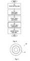
- Fig 4is a flow chart illustrating a method performed in the intermediate node of Fig 2 .
- the methodcan be performed in each of the intermediate nodes of Fig 1 and can be implemented in hardware and/or software.
- one of the lower level nodesis selected as a winning node to be forwarded to the higher level node. This selection is performed as described above with reference to the scheduling module 20.
- a set of input parameters 41are obtained, as described above with reference to the state calculation module 22.
- the input parameterscan comprise input data being associated with the winning node and optionally internal state data of the respective intermediate node.
- output parametersare obtained by finding a matching row in the lookup table using the input parameters as a key, as described above.
- a provide output parameters step 43the output parameters obtained in the preceding step 42 are provided to the higher level node.
- the internal state datasuch as the min token bucket and max token bucket are updated. This can occur as a response to selection of winning input node in the entire network traffic scheduler, or when a winning lower level node is selected.
- Fig 5shows one example of a computer program product 60 comprising computer readable means.
- a computer program 51can be stored, which computer program can cause a controller to execute a method according to embodiments described herein.
- the computer program product 50is an optical disc, such as a CD (compact disc) or a DVD (digital versatile disc) or a Blu-Ray disc.
- the computer program productcould also be embodied as a memory of the network traffic scheduler.
- the computer program 51is here schematically shown as a track on the depicted optical disk, the computer program 51 can be stored in any way which is suitable for the computer program product 50.
Landscapes
- Engineering & Computer Science (AREA)
- Computer Networks & Wireless Communication (AREA)
- Signal Processing (AREA)
- Quality & Reliability (AREA)
- Data Exchanges In Wide-Area Networks (AREA)
Abstract
Description
- The invention relates to network traffic scheduling.
- In traffic scheduling for communications networks, traffic from a large number of inputs often needs to be multiplexed to a single output. This can be effected using a multi-level scheduling hierarchy. Using a variety of parameters, network operators may configure scheduling hierarchies such that the bandwidth, delay and jitter (delay variation) experienced by network users complies with service level agreements.
- The patent application
WO-2009/130218 presents a method for a traffic manager, where the method comprises reading a first data packet comprised in a first queue based on a scheduling priority, the scheduling priority being determined: at least partly on a configured priority of the first queue, at least partly on a first meter value of a first meter associated with the first queue; and at least partly on a second meter value of a second meter associated with a first scheduling node; the first scheduling node being a parent node of the first queue. Desired changes in behaviour of the traffic manager can be effected by changing priority level. - However, there is a need for a more flexible way of configuring selection in a hierarchy for traffic scheduling.
- An object of the invention is to alleviate some of the problems laid forth above.
- In a first aspect, it is presented a method for a network traffic scheduler to select a winning input node, the network traffic scheduler comprising a node hierarchy comprising: a plurality of input nodes; an output node at a top level of the hierarchy; a plurality of intermediate nodes, wherein a subset of the intermediate nodes comprises intermediate nodes being connected to at least one lower level node and one higher level node. The method comprises the steps, for each of the intermediate nodes of the subset, of: selecting a lower level node as a winning node to be forwarded to the higher level node; obtaining a set of input parameters, the input parameters comprising input data being associated with the winning node; obtaining output parameters by finding a matching row in a lookup table using the input parameters as a key, the lookup table being applicable for all combinations of input parameters; and providing the output parameters to the higher level node, wherein, when the higher level node is an intermediate node, at least a subset of the output parameters are used as input parameters for the higher level node.
- By using lookup tables, the relationship between input parameters and output parameters is much more flexible than in the prior art. This allows for implementation of all currently known useful functions, but also allows definition of completely new functions in the future.
- In the step of obtaining output parameters, the lookup table may be one of a plurality of predefined lookup tables selected to be active for the respective intermediate node. This is an efficient way to define what function should be applied.
- In the step of obtaining output parameters, the lookup table may be a freely configurable table. In other words, any output parameters can be defined for each combination of input parameters.
- An output parameter may be an eligibility parameter, which is calculated by performing an AND operation of an eligibility from the matching row of the lookup table and an input eligibility parameter of the winning node.
- The output parameters may comprise a propagated priority of the respective intermediate node.
- The output parameters may comprise a scheduling priority.
- The input parameters may comprise a propagated priority of the winning node.
- The input parameters may comprise a minimum token bucket parameter and a maximum token bucket parameter.
- Each of the input nodes may correspond to a packet queue.
- In the step of obtaining a set of input parameters, the input parameters may further comprise internal state parameters of the respective intermediate node. This can for example be token bucket states, such as for minimum and maximum token buckets.
- The method may further comprise the step, for each of the intermediate nodes of the subset, of: updating the internal state parameter due to the selection of winning input node in the entire network traffic scheduler.
- The method may further comprise the step, for each of the intermediate nodes of the subset, of: updating the internal state parameters when a winning lower level node is selected.
- All the input nodes may be provided on a single input level of the hierarchy.
- A second aspect is a network traffic scheduler arranged to select a winning input node, the network traffic scheduler comprising a node hierarchy. The node hierarchy comprises: a plurality of input nodes; an output node at a top level of the hierarchy; a plurality of intermediate nodes, wherein a subset of the intermediate nodes comprises intermediate nodes being connected to at least one lower level node and one higher level node. Each intermediate nodes of the subset respectively comprises: a scheduling module arranged to select a lower level node as a winning node to be forwarded to the higher level node; a state calculation module arranged to: obtain a set of input parameters, the input parameters comprising input data being associated with the winning node; obtain output parameters by finding a matching row in a lookup table using the input parameters as a key, the lookup table being applicable for all combinations of input parameters; and provide the output parameters to the higher level node. When the higher level node is an intermediate node, at least a subset of the output parameters are arranged to be used as input parameters for the higher level node.
- The input parameters may further comprise internal state parameters of the respective intermediate node.
- A third aspect is a computer program for a network traffic scheduler to select a winning input node, the network traffic scheduler comprising a node hierarchy comprising: plurality of input nodes; an output node at a top level of the hierarchy; a plurality of intermediate nodes. A subset of the intermediate nodes comprises intermediate nodes being connected to at least one lower level node and one higher level node. The computer program comprises computer program code which, when run on the network traffic scheduler, causes the network traffic scheduler to perform the steps of: selecting a lower level node as a winning node to be forwarded to the higher level node; obtaining a set of input parameters, the input parameters comprising input data being associated with the winning node; obtaining output parameters by finding a matching row in a lookup table using the input parameters as a key, the lookup table being applicable for all combinations of input parameters; and providing the output parameters to the higher level node, wherein, when the higher level node is an intermediate node, at least a subset of the output parameters are used as input parameters for the higher level node.
- A fourth aspect is a computer program product comprising a computer program according to the third aspect and a computer readable means on which the computer program is stored.
- It is to be noted that the term subset is not to be interpreted as proper subset, whereby a subset of the intermediate nodes is to be interpreted as some or all of the intermediate nodes.
- It is to be noted that any feature of the first, second, third and fourth aspects may, where appropriate, be applied to any other of these aspects.
- Generally, all terms used in the application are to be interpreted according to their ordinary meaning in the technical field, unless explicitly defined otherwise herein. All references to "a/an/the element, apparatus, component, means, step, etc." are to be interpreted openly as referring to at least one instance of the element, apparatus, component, means, step, etc., unless explicitly stated otherwise. The steps of any method disclosed herein do not have to be performed in the exact order disclosed, unless explicitly stated.
- The invention is now described, by way of example, with reference to the accompanying drawings, in which:
Fig 1 is a schematic diagram disclosing a logical hierarchy of a network traffic scheduler according to one embodiment;Fig 2 is a schematic diagram disclosing logical components of an intermediate node of the logical hierarchy ofFig 1 ;Fig 3 is a schematic diagram illustrating how a lookup table can be selected by a state calculation module of the intermediate node ofFig 2 ;Fig 4 is a flow chart illustrating a method performed in the intermediate node ofFig 2 ; andFig 5 shows one example of a computer program product comprising computer readable means.- The invention will now be described more fully hereinafter with reference to the accompanying drawings, in which certain embodiments of the invention are shown. This invention may, however, be embodied in many different forms and should not be construed as limited to the embodiments set forth herein; rather, these embodiments are provided by way of example so that this disclosure will be thorough and complete, and will fully convey the scope of the invention to those skilled in the art. Like numbers refer to like elements throughout the description.
Fig 1 is a schematic diagram disclosing a logical hierarchy of a network traffic scheduler 1 according to one embodiment. The logic of network traffic scheduler 1 connects oneinput node 5 to anoutput node 2, via a number ofintermediate nodes 3 to thereby select a winning node to schedule traffic. Theinput nodes 5 are here provided on an input level 15 and theoutput node 2 is provided on an output level 10.Intermediate nodes 3 are provided on intermediate levels 11-14.- Each
input node 5 can correspond to a queue for storing data that is associated with a data source or a data recipient, such as a user or a user-specific service. The data may be individual data packets or datagrams, such as IP packets, ATM frames, Frame Relay Protocol data units (PDU), Ethernet packets or any other packet switched data. Optionally, several individual data packets can be grouped together in packages for easier handling. In other words, data is selected for dequeuing by the network traffic scheduler 1 one data unit at a time, where each data unit can comprise a single data packet or each data unit can be a package comprising several data packets. - While the hierarchy is here shown with input nodes all being provided on the same input level 15, the hierarchy could also be arranged with inputs provided at different levels 11-15 under the output level 10.
- Regardless of where the
input nodes 5 are provided, a plurality ofintermediate nodes 3 are provided between theinput nodes 5 and theoutput node 2 to effect scheduling and shaping of data. - The logical hierarchy is shown to illustrate the selection process where one of a plurality of
queues 5 is selected to supply data to anoutput node 2 of the network traffic scheduler 1. It is to be noted that in implementation, there are no be physical components corresponding to the nodes in the hierarchy; instead the hierarchy can be implemented using software and/or hardware e.g. using a network processor, application-specific integrated circuit (ASIC), field-programmable gate array (FPGA) or central processing unit (CPU). - The network traffic scheduler can for instance be configured to provide a desired connectivity service, e.g. by ensuring that the bandwidth complies with service level agreements of attached users. The services level agreements can describe quality of service parameters such as minimum bandwidth, maximum bandwidth, latency, jitter and loss probability for traffic received from or transmitted to a network user. The service level agreements can differ between users.
- Data made available on the
input nodes 5 are made available for scheduling and dequeuing, whereby a selected data unit is dequeued from its input node and transferred to theoutput node 2. The selection is performed using theintermediate nodes 3 of the hierarchy to control the dequeuing of data as determined by the network traffic scheduler 1. - While the hierarchy of
Fig 1 is disclosed using six levels 10-15, any number of levels can be used, as long as there areintermediate nodes 3 provided betweeninput nodes 5 and theoutput node 2. Fig 2 is a schematic diagram disclosing logical components of anintermediate node 3 of the logical hierarchy ofFig 1 . The intermediate node is connected to at least onelower level node 27a-i, and onehigher level node 28. The lower level node/nodes can beinput nodes 5 or otherintermediate nodes 3. Thehigher level node 28 can be theoutput node 2 or otherintermediate nodes 3.- The
intermediate node 3 comprises ascheduling module 20 arranged to select one of the at least onelower level node 27a-i as a winning node to be forwarded to thehigher level node 28. - To effect the selection, the
intermediate node 3 can utilise one or more of the followinginput parameters 30a-i received as output parameters from thelower level nodes 27a-i and/or internal parameters. - One parameter is an eligibility parameter which is a flag associated with each
lower level node 27a-i. The eligibility parameter indicates whether thelower level node 27a-i is allowed to be selected or not. - Another parameter is scheduling priority, which is associated with each
lower level node 27a-i. Scheduling priority can be used to handle delay sensitive and high priority traffic. In one embodiment, three bits are used for scheduling priority, which gives eight possible values for the scheduling priority. Other number of scheduling priorities can also be used. When propagated priority (see below) is not used, using scheduling priority is one way to handle delay sensitive traffic by configuring scheduling priority nodes all the way through the hierarchies. - Another parameter is propagated priority, also associated with each
lower level node 27a-i. Propagated priority can be used to handle delay sensitive traffic in a user oriented scheduling hierarchy. In a hierarchy where a certain user queue is used for traffic of certain service class, it is difficult to provide low latency for delay sensitive traffic just by reserving bandwidth at all upper levels. Propagated priority effects this in more efficient way. - In addition to eligibility, propagated priority is, as suggested by the name, propagated to the higher level node, from which it is propagated further.
Intermediate nodes 3 will prefer lower level nodes with higher propagated priority to child nodes with lower propagated priority queues. This enables delay sensitive data to be served faster. The manner in which propagated priority is propagated is optionally configurable per node or per level. The use of lookup tables as is explained in more detail below. - Moreover, internal state parameters can optionally be used by the
scheduling module 20 to select a winner from thelower level nodes 27a-i, using e.g. round robin or DWRR (Deficit Weighted Round Robin). - A round robin scheme can be used to achieve a degree of fairness between the
lower level nodes 27a-i. It is used as default at all levels and priorities. In case round robin scheduling is used among nodes with significantly different packet sizes, the scheduled bandwidth of nodes with large packets is significantly larger than the scheduled bandwidth of nodes with small packets, and jitter can be created. In that case other scheduling methods can be applied, such as DWRR. - DWRR is an implementation of WFQ (weighted fair queuing). It provides fair sharing of bandwidth in a work conserving manner and permits configuration of bandwidth ratios by means of weights. DWRR is particularly useful in an oversubscribed scenario.
- In an oversubscribed scenario the demand for bandwidth is higher than the available bandwidth at least some of the time.
- Unlike the bandwidth resulting from shaping, e.g. implemented using token buckets as described below, the bandwidth from DWRR scheduling can vary over time, even if accurate ratios are maintained. Oversubscription scenarios are based on statistic multiplexing and this creates congestion conditions that vary in their length and severity. However, the algorithm results in that over a long period of time, the bandwidth ratios of the nodes that are competing for the limited bandwidth resource are accurate.
- In both round robin and DWRR, an internal state is kept by the
scheduling module 20, e.g. to know whichlower level node 27a-i was last served. - Once a winning lower level node has been selected by the
scheduling module 20, astate calculation module 22 can be used to obtain output parameters to provide to thehigher level node 28. - The
state calculation module 22 obtains a set of input parameters, wherein the input parameters comprises input data being associated with the winning node, such as one or more of the parameters described above. Optionally,internal state parameters 25 of theintermediate node 3 are also obtained. - The
internal state parameters 25 can for example be dualtoken bucket data 25 for minimum and maximum shaping in accordance with service level agreements. For example, a minimum committed bandwidth can be handled using a min token bucket and is referred to as min bandwidth, e.g. represented by one bit. An excess bandwidth can be handled by a max token bucket and is referred to as max bandwidth, e.g. represented by one bit. The intermediate node thus uses the min token bucket for bandwidth guarantee and the max token bucket the excess bandwidth rate shaping. - Min token bucket is used to control the guaranteed bandwidth. This bandwidth is provided under any condition unless it is oversubscribed. Max token bucket is used to limit a specific node to a specific maximum bandwidth. This is required in case other nodes do not have data, but still preventing a lower level node from using all the available bandwidth in violation of its service level agreement, or because it is not desirable that it consumes the higher intermediate node bandwidth (tokens) that will be required at a later time for more important traffic. Min conforming nodes are preferred (have strict priority) over max conforming nodes. At each intermediate node, all min nodes (nodes with conforming min token bucket) are served before any max node (node with non-conforming min token bucket and conforming max token bucket). This scheme ensures that min bandwidth is provided before any max bandwidth.
- Using the input parameters, the
state calculation module 22 obtainsoutput parameters 31 by finding a matching row in a lookup table 24. The input parameters are used as a key or address to find theoutput parameters 31 to use. The lookup table 24 is structured such that it is applicable for all combinations of input parameters. - For example, if the input parameters for state calculation are propagated priority (three bits), min token bucket (one bit) and max token bucket (one bit), there are five bits for the input parameters, which results in 2^5 = 32 possible combinations of input parameters. The lookup table 24 can then use the input parameters as table key and may in this example have 32 rows to cover all possible values of input parameters, where output parameters are provided in each row. Optionally, associative memory with wildcards can be used to reduce the number of rows and still cover all possible values of input parameters.
- Output parameters may for example include propagated priority (three bits), scheduled priority (three bits) and eligibility (one bit). Optionally, two bits can be output to update min and max token buckets for the higher level node, respectively. In this example, the output parameters thus consist of seven or nine bits.
- It is to be noted that the number of bits for each parameter presented herein are mere examples and can, in each implementation, be freely selected for each parameter to be any suitable number of bits.
- The lookup table 24 thus defines the output parameters for each value of input parameters, in effect providing a flexible way of defining a function f for output parameters = f(input parameters).
- At least some of the
output parameters 31 provided to thehigher level node 28 are used as input parameters for thehigher level node 28, unless the higher level node is theoutput node 2. - One parameter of the
output parameters 31 can be the eligibility parameter. The eligibility parameter can be calculated by performing an AND operation, in a multiplier or ANDgate 21, of an eligibility from the matching row of the lookup table and an input eligibility parameter of the winning node. - An
identity 32 of the winning node is also provided to the higher level node. The winning node identity of each level is propagated upwards in the hierarchy in this way, such that eventually a winning node of the entire hierarchy is determined. Fig 3 is a schematic diagram illustrating how the lookup table is selected by thestate calculation module 22 of theintermediate node 3 ofFig 2 . Theintermediate node 3 comprises a plurality of predefined lookup tables 24a-n. Each such predefined lookup table thus defines a function for state calculation. Eachintermediate node 3 is configured to select an active one of the predefined lookup tables 24a-n. The selected lookup table is used when determining the output parameters. This configuration can be completely static. Alternatively, it may be configured at boot time or reconfigured dynamically on demand, potentially after each data unit dequeuing. The dynamic selection can be controlled by an external control device.- Optionally, instead of selecting a desired lookup table, the content of the lookup table can be altered to effect the desired function. In other words, in such an embodiment, the lookup table is a freely configurable table.
- By means of this selectable behaviour of the state calculation, a completely new level of flexibility is provided. The selection of function using the lookup tables can be performed uniformly for all intermediate nodes, separately for each level in the hierarchy or separately for each individual intermediate node.
Fig 4 is a flow chart illustrating a method performed in the intermediate node ofFig 2 . The method can be performed in each of the intermediate nodes ofFig 1 and can be implemented in hardware and/or software.- In an initial select winning
node step 40, one of the lower level nodes is selected as a winning node to be forwarded to the higher level node. This selection is performed as described above with reference to thescheduling module 20. - In an obtain input parameters step 41, a set of
input parameters 41 are obtained, as described above with reference to thestate calculation module 22. The input parameters can comprise input data being associated with the winning node and optionally internal state data of the respective intermediate node. - In an obtain output parameters step 42, output parameters are obtained by finding a matching row in the lookup table using the input parameters as a key, as described above.
- In a provide output parameters step 43, the output parameters obtained in the preceding
step 42 are provided to the higher level node. - In an optional update internal state data step 44, the internal state data, such as the min token bucket and max token bucket are updated. This can occur as a response to selection of winning input node in the entire network traffic scheduler, or when a winning lower level node is selected.
Fig 5 shows one example of a computer program product 60 comprising computer readable means. On this computer readable means acomputer program 51 can be stored, which computer program can cause a controller to execute a method according to embodiments described herein. In this example, thecomputer program product 50 is an optical disc, such as a CD (compact disc) or a DVD (digital versatile disc) or a Blu-Ray disc. As explained above, the computer program product could also be embodied as a memory of the network traffic scheduler. While thecomputer program 51 is here schematically shown as a track on the depicted optical disk, thecomputer program 51 can be stored in any way which is suitable for thecomputer program product 50.- The invention has mainly been described above with reference to a few embodiments. However, as is readily appreciated by a person skilled in the art, other embodiments than the ones disclosed above are equally possible within the scope of the invention, as defined by the appended patent claims.
Claims (15)
- A method for a network traffic scheduler to select a winning input node, the network traffic scheduler comprising a node hierarchy comprising: a plurality of input nodes (5); an output node (2) at a top level of the hierarchy; a plurality of intermediate nodes (3), wherein a subset of the intermediate nodes comprises intermediate nodes (3) being connected to at least one lower level node (27a-i) and one higher level node (28), the method comprising the steps, for each of the intermediate nodes of the subset, of:selecting (40) a lower level node as a winning node to be forwarded to the higher level node (28);obtaining a set of input parameters (41), the input parameters comprising input data being associated with the winning node;obtaining output parameters (42) by finding a matching row in a lookup table (24, 24a-n) using the input parameters as a key, the lookup table (24, 24a-n) being applicable for all combinations of input parameters; andproviding the output parameters (43) to the higher level node (28), wherein, when the higher level node is an intermediate node (3), at least a subset of the output parameters are used as input parameters for the higher level node (28).
- The method according to claim 1, wherein in the step (42) of obtaining output parameters, the lookup table is one of a plurality of predefined lookup tables (24a-n) selected to be active for the respective intermediate node (3).
- The method according to claim 1, wherein in the step of obtaining output parameters, the lookup table is a freely configurable table.
- The method according to any one of the preceding claims wherein an output parameter is an eligibility parameter, which is calculated by performing an AND operation of an eligibility from the matching row of the lookup table and an input eligibility parameter of the winning node.
- The method according to any one of the preceding claims, wherein the output parameters comprise a propagated priority of the respective intermediate node (3) .
- The method according to any one of the preceding claims, wherein the input parameters comprise a minimum token bucket parameter and a maximum token bucket parameter.
- The method according to any one of the preceding claims wherein each of the input nodes (5) corresponds to a packet queue.
- The method according to any one of the preceding claims, wherein in the step (41) of obtaining a set of input parameters, the input parameters further comprise internal state parameters (25) of the respective intermediate node.
- The method according to claim 8, further comprising the step, for each of the intermediate nodes of the subset, of: updating the internal state parameter (25) due to the selection of winning input node in the entire network traffic scheduler.
- The method according to claim 8 or 9, further comprising the step, for each of the intermediate nodes of the subset, of: updating the internal state parameters (25) when a winning lower level node is selected.
- The method according to any one of the preceding claims, wherein all the input nodes are provided on a single input level (15) of the hierarchy.
- A network traffic scheduler (1) arranged to select a winning input node (2), the network traffic scheduler comprising a node hierarchy comprising:a plurality of input nodes (5);an output node (2) at a top level of the hierarchy;a plurality of intermediate nodes (3), wherein a subset of the intermediate nodes comprises intermediate nodes (3) being connected to at least one lower level node (27a-i) and one higher level node (28), wherein each intermediate nodes (3) of the subset respectively comprises:a scheduling module (20) arranged to select a lower level node (27a-i) as a winning node to be forwarded to the higher level node (28);a state calculation module (22) arranged to: obtain a set of input parameters, the input parameters comprising input data being associated with the winning node; obtain output parameters (31) by finding a matching row in a lookup table (24, 24a-n) using the input parameters as a key, the lookup table (24, 24a-n) being applicable for all combinations of input parameters; and provide the output parameters (31) to the higher level node (28), wherein, when the higher level node is an intermediate node (3), at least a subset of the output parameters are arranged to be used as input parameters for the higher level node (28).
- The network traffic scheduler (1) according to claim 12, wherein the input parameters further comprise internal state parameters (25) of the respective intermediate node.
- A computer program (51) for a network traffic scheduler to select a winning input node, the network traffic scheduler comprising a node hierarchy comprising: plurality of input nodes (5); an output node (2) at a top level of the hierarchy; a plurality of intermediate nodes (3), wherein a subset of the intermediate nodes comprises intermediate nodes (3) being connected to at least one lower level node (27a-i) and one higher level node (28), the computer program comprising computer program code which, when run on the network traffic scheduler, causes the network traffic scheduler to perform the steps of:selecting (40) a lower level node as a winning node to be forwarded to the higher level node (28);obtaining a set of input parameters (41), the input parameters comprising input data being associated with the winning node;obtaining output parameters (42) by finding a matching row in a lookup table (24, 24a-n) using the input parameters as a key, the lookup table (24, 24a-n) being applicable for all combinations of input parameters; andproviding the output parameters (43) to the higher level node (28), wherein, when the higher level node is an intermediate node (3), at least a subset of the output parameters are used as input parameters for the higher level node (28).
- A computer program product (50) comprising a computer program (51) according to claim 14 and a computer readable means on which the computer program is stored.
Priority Applications (5)
| Application Number | Priority Date | Filing Date | Title |
|---|---|---|---|
| EP11166496.7AEP2525534B1 (en) | 2011-05-18 | 2011-05-18 | Network traffic scheduler and associated method, computer program and computer program product |
| PCT/IB2012/001149WO2012156824A1 (en) | 2011-05-18 | 2012-05-18 | Network traffic scheduler and associated method, computer program and computer program product |
| US13/475,445US9042220B2 (en) | 2011-05-18 | 2012-05-18 | Network traffic scheduler and associated method, computer program and computer program product |
| CN201280024007.6ACN103548303B (en) | 2011-05-18 | 2012-05-18 | network traffic scheduler and associated method, computer program and computer program product |
| TW101117871ATWI593253B (en) | 2011-05-18 | 2012-05-18 | Network traffic scheduling system and method thereof, computer program and computer program product |
Applications Claiming Priority (1)
| Application Number | Priority Date | Filing Date | Title |
|---|---|---|---|
| EP11166496.7AEP2525534B1 (en) | 2011-05-18 | 2011-05-18 | Network traffic scheduler and associated method, computer program and computer program product |
Publications (2)
| Publication Number | Publication Date |
|---|---|
| EP2525534A1true EP2525534A1 (en) | 2012-11-21 |
| EP2525534B1 EP2525534B1 (en) | 2018-04-18 |
Family
ID=44117806
Family Applications (1)
| Application Number | Title | Priority Date | Filing Date |
|---|---|---|---|
| EP11166496.7ANot-in-forceEP2525534B1 (en) | 2011-05-18 | 2011-05-18 | Network traffic scheduler and associated method, computer program and computer program product |
Country Status (5)
| Country | Link |
|---|---|
| US (1) | US9042220B2 (en) |
| EP (1) | EP2525534B1 (en) |
| CN (1) | CN103548303B (en) |
| TW (1) | TWI593253B (en) |
| WO (1) | WO2012156824A1 (en) |
Cited By (4)
| Publication number | Priority date | Publication date | Assignee | Title |
|---|---|---|---|---|
| EP3076620A1 (en)* | 2015-04-01 | 2016-10-05 | Honeywell International Inc. | Scheduling of different traffic classes |
| US9769075B2 (en) | 2015-04-01 | 2017-09-19 | Honeywell International Inc. | Interference cognizant network scheduling |
| US9769082B2 (en) | 2015-04-01 | 2017-09-19 | Honeywell International Inc. | System and method for network bandwidth, buffers and timing management using hybrid scheduling of traffic with different priorities and guarantees |
| CN113973342A (en)* | 2021-10-29 | 2022-01-25 | 北京天融信网络安全技术有限公司 | Flow control method and device, electronic equipment and storage medium |
Families Citing this family (6)
| Publication number | Priority date | Publication date | Assignee | Title |
|---|---|---|---|---|
| US10680957B2 (en) | 2014-05-28 | 2020-06-09 | Cavium International | Method and apparatus for analytics in a network switch |
| US9871733B2 (en)* | 2014-11-13 | 2018-01-16 | Cavium, Inc. | Policer architecture |
| EP3818439A4 (en) | 2018-07-05 | 2022-04-27 | Mythic, Inc. | SYSTEMS AND METHODS FOR IMPLEMENTING AN INTELLIGENCE PROCESSING COMPUTER ARCHITECTURE |
| US11902167B2 (en)* | 2019-07-04 | 2024-02-13 | Nippon Telegraph And Telephone Corporation | Communication apparatus having delay guarantee shaping function |
| TWI748613B (en)* | 2020-08-27 | 2021-12-01 | 瑞昱半導體股份有限公司 | Switch |
| CN112434483B (en)* | 2020-12-18 | 2024-07-16 | 深圳国微芯科技有限公司 | Method for generating data transmission system and data transmission system |
Citations (2)
| Publication number | Priority date | Publication date | Assignee | Title |
|---|---|---|---|---|
| US6487213B1 (en)* | 1998-01-05 | 2002-11-26 | Polytechnic University | Methods and apparatus for fairly arbitrating contention for an output port |
| WO2009130218A1 (en) | 2008-04-24 | 2009-10-29 | Xelerated Ab | A traffic manager and a method for a traffic manager |
Family Cites Families (12)
| Publication number | Priority date | Publication date | Assignee | Title |
|---|---|---|---|---|
| US6667984B1 (en)* | 1998-05-15 | 2003-12-23 | Polytechnic University | Methods and apparatus for arbitrating output port contention in a switch having virtual output queuing |
| US6901074B1 (en)* | 1998-12-03 | 2005-05-31 | Secretary Of Agency Of Industrial Science And Technology | Communication method and communications system |
| US7477650B2 (en)* | 2003-10-02 | 2009-01-13 | Alcatel Lucent | Method and apparatus for frame-aware and pipelined hierarchical scheduling |
| US7460544B2 (en)* | 2004-12-29 | 2008-12-02 | Intel Corporation | Flexible mesh structure for hierarchical scheduling |
| JP4698673B2 (en)* | 2005-06-02 | 2011-06-08 | 日本電気株式会社 | Switch device, switching method, and switch control program |
| US8130648B2 (en)* | 2006-01-04 | 2012-03-06 | Broadcom Corporation | Hierarchical queue shaping |
| US7969884B1 (en)* | 2008-05-09 | 2011-06-28 | Nortel Networks Limited | Method and system for weight and rate scheduling |
| US8027346B1 (en)* | 2008-05-29 | 2011-09-27 | Avaya Inc. | Method and system for scheduler dominated merge of state changes |
| US7995597B2 (en)* | 2008-10-14 | 2011-08-09 | Nortel Networks Limited | Method and system for weighted fair queuing |
| US7986706B2 (en)* | 2009-04-29 | 2011-07-26 | Telefonaktiebolaget Lm Ericsson | Hierarchical pipelined distributed scheduling traffic manager |
| CN101729412B (en)* | 2009-11-05 | 2012-03-14 | 北京超图软件股份有限公司 | Distributed level cluster method and system of geographic information service |
| US8391305B2 (en)* | 2009-12-30 | 2013-03-05 | International Business Machines Corporation | Assignment constraint matrix for assigning work from multiple sources to multiple sinks |
- 2011
- 2011-05-18EPEP11166496.7Apatent/EP2525534B1/ennot_activeNot-in-force
- 2012
- 2012-05-18TWTW101117871Apatent/TWI593253B/ennot_activeIP Right Cessation
- 2012-05-18CNCN201280024007.6Apatent/CN103548303B/ennot_activeExpired - Fee Related
- 2012-05-18WOPCT/IB2012/001149patent/WO2012156824A1/enactiveApplication Filing
- 2012-05-18USUS13/475,445patent/US9042220B2/enactiveActive
Patent Citations (2)
| Publication number | Priority date | Publication date | Assignee | Title |
|---|---|---|---|---|
| US6487213B1 (en)* | 1998-01-05 | 2002-11-26 | Polytechnic University | Methods and apparatus for fairly arbitrating contention for an output port |
| WO2009130218A1 (en) | 2008-04-24 | 2009-10-29 | Xelerated Ab | A traffic manager and a method for a traffic manager |
Cited By (5)
| Publication number | Priority date | Publication date | Assignee | Title |
|---|---|---|---|---|
| EP3076620A1 (en)* | 2015-04-01 | 2016-10-05 | Honeywell International Inc. | Scheduling of different traffic classes |
| US9762501B2 (en) | 2015-04-01 | 2017-09-12 | Honeywell International Inc. | Systematic hybrid network scheduling for multiple traffic classes with host timing and phase constraints |
| US9769075B2 (en) | 2015-04-01 | 2017-09-19 | Honeywell International Inc. | Interference cognizant network scheduling |
| US9769082B2 (en) | 2015-04-01 | 2017-09-19 | Honeywell International Inc. | System and method for network bandwidth, buffers and timing management using hybrid scheduling of traffic with different priorities and guarantees |
| CN113973342A (en)* | 2021-10-29 | 2022-01-25 | 北京天融信网络安全技术有限公司 | Flow control method and device, electronic equipment and storage medium |
Also Published As
| Publication number | Publication date |
|---|---|
| TWI593253B (en) | 2017-07-21 |
| CN103548303B (en) | 2017-02-08 |
| US20120294317A1 (en) | 2012-11-22 |
| CN103548303A (en) | 2014-01-29 |
| TW201304460A (en) | 2013-01-16 |
| US9042220B2 (en) | 2015-05-26 |
| WO2012156824A1 (en) | 2012-11-22 |
| EP2525534B1 (en) | 2018-04-18 |
Similar Documents
| Publication | Publication Date | Title |
|---|---|---|
| EP2525534A1 (en) | Network traffic scheduler and associated method, computer program and computer program product | |
| US8230110B2 (en) | Work-conserving packet scheduling in network devices | |
| US11171891B2 (en) | Congestion drop decisions in packet queues | |
| EP2695334B1 (en) | Packet scheduling method and apparatus | |
| US8571048B2 (en) | Dynamic memory queue depth algorithm | |
| US10447608B2 (en) | Packet scheduling using hierarchical scheduling process with priority propagation | |
| EP3073680B1 (en) | Methods, queueing system, network element and network system for queueing and processing of packets | |
| US20050249220A1 (en) | Hierarchical QoS behavioral model | |
| US10110515B2 (en) | Packet scheduling using hierarchical scheduling process | |
| RU2643666C2 (en) | Method and device to control virtual output queue authorization and also computer storage media | |
| US8379518B2 (en) | Multi-stage scheduler with processor resource and bandwidth resource allocation | |
| US10623329B2 (en) | Queuing system to predict packet lifetime in a computing device | |
| US11336582B1 (en) | Packet scheduling | |
| Mariño et al. | Elastic queueing engine for time sensitive networking | |
| US9369397B1 (en) | Apparatus to achieve quality of service (QoS) without requiring fabric speedup | |
| Luangsomboon et al. | HLS: A packet scheduler for hierarchical fairness | |
| US7826354B2 (en) | Method preserving delay properties and an apparatus for scheduling transmission link capacity between packet switched telecommunications flows | |
| Asaduzzaman et al. | The eight class of service model-an improvement over the five classes of service | |
| CN106487713A (en) | A kind of service quality multiplexing method and device | |
| Kulhari et al. | Traffic shaping at differentiated services enabled edge router using adaptive packet allocation to router input queue | |
| KR100745679B1 (en) | Packet Scheduling Method and Apparatus Using Adaptive Round Robin | |
| Hu et al. | Dynamic queuing sharing mechanism for per-flow quality of service control | |
| Hong et al. | Fair scheduling on parallel bonded channels with intersecting bonding groups | |
| US7813283B1 (en) | Circuit and method for arbitration | |
| Magadum et al. | CT-PIFO: A Congruity Tree Based Packet Scheduler to Improve Flow Completion Time |
Legal Events
| Date | Code | Title | Description |
|---|---|---|---|
| PUAI | Public reference made under article 153(3) epc to a published international application that has entered the european phase | Free format text:ORIGINAL CODE: 0009012 | |
| AK | Designated contracting states | Kind code of ref document:A1 Designated state(s):AL AT BE BG CH CY CZ DE DK EE ES FI FR GB GR HR HU IE IS IT LI LT LU LV MC MK MT NL NO PL PT RO RS SE SI SK SM TR | |
| AX | Request for extension of the european patent | Extension state:BA ME | |
| 17P | Request for examination filed | Effective date:20130521 | |
| 17Q | First examination report despatched | Effective date:20170309 | |
| REG | Reference to a national code | Ref country code:DE Ref legal event code:R079 Ref document number:602011047528 Country of ref document:DE Free format text:PREVIOUS MAIN CLASS: H04L0012560000 Ipc:H04L0012869000 | |
| GRAP | Despatch of communication of intention to grant a patent | Free format text:ORIGINAL CODE: EPIDOSNIGR1 | |
| RIC1 | Information provided on ipc code assigned before grant | Ipc:H04L 12/931 20130101ALI20171019BHEP Ipc:H04L 12/937 20130101ALI20171019BHEP Ipc:H04L 12/863 20130101ALI20171019BHEP Ipc:H04L 12/861 20130101ALI20171019BHEP Ipc:H04L 12/869 20130101AFI20171019BHEP | |
| INTG | Intention to grant announced | Effective date:20171114 | |
| GRAS | Grant fee paid | Free format text:ORIGINAL CODE: EPIDOSNIGR3 | |
| GRAA | (expected) grant | Free format text:ORIGINAL CODE: 0009210 | |
| AK | Designated contracting states | Kind code of ref document:B1 Designated state(s):AL AT BE BG CH CY CZ DE DK EE ES FI FR GB GR HR HU IE IS IT LI LT LU LV MC MK MT NL NO PL PT RO RS SE SI SK SM TR | |
| REG | Reference to a national code | Ref country code:GB Ref legal event code:FG4D | |
| REG | Reference to a national code | Ref country code:CH Ref legal event code:EP | |
| REG | Reference to a national code | Ref country code:DE Ref legal event code:R096 Ref document number:602011047528 Country of ref document:DE | |
| REG | Reference to a national code | Ref country code:AT Ref legal event code:REF Ref document number:991589 Country of ref document:AT Kind code of ref document:T Effective date:20180515 | |
| REG | Reference to a national code | Ref country code:IE Ref legal event code:FG4D | |
| REG | Reference to a national code | Ref country code:FR Ref legal event code:PLFP Year of fee payment:8 | |
| REG | Reference to a national code | Ref country code:NL Ref legal event code:MP Effective date:20180418 | |
| REG | Reference to a national code | Ref country code:LT Ref legal event code:MG4D | |
| PG25 | Lapsed in a contracting state [announced via postgrant information from national office to epo] | Ref country code:NL Free format text:LAPSE BECAUSE OF FAILURE TO SUBMIT A TRANSLATION OF THE DESCRIPTION OR TO PAY THE FEE WITHIN THE PRESCRIBED TIME-LIMIT Effective date:20180418 | |
| PG25 | Lapsed in a contracting state [announced via postgrant information from national office to epo] | Ref country code:NO Free format text:LAPSE BECAUSE OF FAILURE TO SUBMIT A TRANSLATION OF THE DESCRIPTION OR TO PAY THE FEE WITHIN THE PRESCRIBED TIME-LIMIT Effective date:20180718 Ref country code:FI Free format text:LAPSE BECAUSE OF FAILURE TO SUBMIT A TRANSLATION OF THE DESCRIPTION OR TO PAY THE FEE WITHIN THE PRESCRIBED TIME-LIMIT Effective date:20180418 Ref country code:LT Free format text:LAPSE BECAUSE OF FAILURE TO SUBMIT A TRANSLATION OF THE DESCRIPTION OR TO PAY THE FEE WITHIN THE PRESCRIBED TIME-LIMIT Effective date:20180418 Ref country code:PL Free format text:LAPSE BECAUSE OF FAILURE TO SUBMIT A TRANSLATION OF THE DESCRIPTION OR TO PAY THE FEE WITHIN THE PRESCRIBED TIME-LIMIT Effective date:20180418 Ref country code:BG Free format text:LAPSE BECAUSE OF FAILURE TO SUBMIT A TRANSLATION OF THE DESCRIPTION OR TO PAY THE FEE WITHIN THE PRESCRIBED TIME-LIMIT Effective date:20180718 Ref country code:ES Free format text:LAPSE BECAUSE OF FAILURE TO SUBMIT A TRANSLATION OF THE DESCRIPTION OR TO PAY THE FEE WITHIN THE PRESCRIBED TIME-LIMIT Effective date:20180418 Ref country code:AL Free format text:LAPSE BECAUSE OF FAILURE TO SUBMIT A TRANSLATION OF THE DESCRIPTION OR TO PAY THE FEE WITHIN THE PRESCRIBED TIME-LIMIT Effective date:20180418 Ref country code:SE Free format text:LAPSE BECAUSE OF FAILURE TO SUBMIT A TRANSLATION OF THE DESCRIPTION OR TO PAY THE FEE WITHIN THE PRESCRIBED TIME-LIMIT Effective date:20180418 | |
| PG25 | Lapsed in a contracting state [announced via postgrant information from national office to epo] | Ref country code:HR Free format text:LAPSE BECAUSE OF FAILURE TO SUBMIT A TRANSLATION OF THE DESCRIPTION OR TO PAY THE FEE WITHIN THE PRESCRIBED TIME-LIMIT Effective date:20180418 Ref country code:RS Free format text:LAPSE BECAUSE OF FAILURE TO SUBMIT A TRANSLATION OF THE DESCRIPTION OR TO PAY THE FEE WITHIN THE PRESCRIBED TIME-LIMIT Effective date:20180418 Ref country code:LV Free format text:LAPSE BECAUSE OF FAILURE TO SUBMIT A TRANSLATION OF THE DESCRIPTION OR TO PAY THE FEE WITHIN THE PRESCRIBED TIME-LIMIT Effective date:20180418 Ref country code:GR Free format text:LAPSE BECAUSE OF FAILURE TO SUBMIT A TRANSLATION OF THE DESCRIPTION OR TO PAY THE FEE WITHIN THE PRESCRIBED TIME-LIMIT Effective date:20180719 | |
| REG | Reference to a national code | Ref country code:CH Ref legal event code:PL | |
| REG | Reference to a national code | Ref country code:AT Ref legal event code:MK05 Ref document number:991589 Country of ref document:AT Kind code of ref document:T Effective date:20180418 | |
| PG25 | Lapsed in a contracting state [announced via postgrant information from national office to epo] | Ref country code:PT Free format text:LAPSE BECAUSE OF FAILURE TO SUBMIT A TRANSLATION OF THE DESCRIPTION OR TO PAY THE FEE WITHIN THE PRESCRIBED TIME-LIMIT Effective date:20180820 | |
| REG | Reference to a national code | Ref country code:DE Ref legal event code:R097 Ref document number:602011047528 Country of ref document:DE | |
| REG | Reference to a national code | Ref country code:BE Ref legal event code:MM Effective date:20180531 | |
| PG25 | Lapsed in a contracting state [announced via postgrant information from national office to epo] | Ref country code:DK Free format text:LAPSE BECAUSE OF FAILURE TO SUBMIT A TRANSLATION OF THE DESCRIPTION OR TO PAY THE FEE WITHIN THE PRESCRIBED TIME-LIMIT Effective date:20180418 Ref country code:MC Free format text:LAPSE BECAUSE OF FAILURE TO SUBMIT A TRANSLATION OF THE DESCRIPTION OR TO PAY THE FEE WITHIN THE PRESCRIBED TIME-LIMIT Effective date:20180418 Ref country code:SK Free format text:LAPSE BECAUSE OF FAILURE TO SUBMIT A TRANSLATION OF THE DESCRIPTION OR TO PAY THE FEE WITHIN THE PRESCRIBED TIME-LIMIT Effective date:20180418 Ref country code:RO Free format text:LAPSE BECAUSE OF FAILURE TO SUBMIT A TRANSLATION OF THE DESCRIPTION OR TO PAY THE FEE WITHIN THE PRESCRIBED TIME-LIMIT Effective date:20180418 Ref country code:CZ Free format text:LAPSE BECAUSE OF FAILURE TO SUBMIT A TRANSLATION OF THE DESCRIPTION OR TO PAY THE FEE WITHIN THE PRESCRIBED TIME-LIMIT Effective date:20180418 Ref country code:AT Free format text:LAPSE BECAUSE OF FAILURE TO SUBMIT A TRANSLATION OF THE DESCRIPTION OR TO PAY THE FEE WITHIN THE PRESCRIBED TIME-LIMIT Effective date:20180418 Ref country code:EE Free format text:LAPSE BECAUSE OF FAILURE TO SUBMIT A TRANSLATION OF THE DESCRIPTION OR TO PAY THE FEE WITHIN THE PRESCRIBED TIME-LIMIT Effective date:20180418 | |
| REG | Reference to a national code | Ref country code:IE Ref legal event code:MM4A | |
| PLBE | No opposition filed within time limit | Free format text:ORIGINAL CODE: 0009261 | |
| STAA | Information on the status of an ep patent application or granted ep patent | Free format text:STATUS: NO OPPOSITION FILED WITHIN TIME LIMIT | |
| PG25 | Lapsed in a contracting state [announced via postgrant information from national office to epo] | Ref country code:SM Free format text:LAPSE BECAUSE OF FAILURE TO SUBMIT A TRANSLATION OF THE DESCRIPTION OR TO PAY THE FEE WITHIN THE PRESCRIBED TIME-LIMIT Effective date:20180418 Ref country code:IT Free format text:LAPSE BECAUSE OF FAILURE TO SUBMIT A TRANSLATION OF THE DESCRIPTION OR TO PAY THE FEE WITHIN THE PRESCRIBED TIME-LIMIT Effective date:20180418 Ref country code:CH Free format text:LAPSE BECAUSE OF NON-PAYMENT OF DUE FEES Effective date:20180531 Ref country code:LI Free format text:LAPSE BECAUSE OF NON-PAYMENT OF DUE FEES Effective date:20180531 | |
| 26N | No opposition filed | Effective date:20190121 | |
| PG25 | Lapsed in a contracting state [announced via postgrant information from national office to epo] | Ref country code:LU Free format text:LAPSE BECAUSE OF NON-PAYMENT OF DUE FEES Effective date:20180518 | |
| PG25 | Lapsed in a contracting state [announced via postgrant information from national office to epo] | Ref country code:IE Free format text:LAPSE BECAUSE OF NON-PAYMENT OF DUE FEES Effective date:20180518 | |
| PG25 | Lapsed in a contracting state [announced via postgrant information from national office to epo] | Ref country code:SI Free format text:LAPSE BECAUSE OF FAILURE TO SUBMIT A TRANSLATION OF THE DESCRIPTION OR TO PAY THE FEE WITHIN THE PRESCRIBED TIME-LIMIT Effective date:20180418 Ref country code:BE Free format text:LAPSE BECAUSE OF NON-PAYMENT OF DUE FEES Effective date:20180531 | |
| PGFP | Annual fee paid to national office [announced via postgrant information from national office to epo] | Ref country code:FR Payment date:20190528 Year of fee payment:9 | |
| PGFP | Annual fee paid to national office [announced via postgrant information from national office to epo] | Ref country code:GB Payment date:20190529 Year of fee payment:9 | |
| PG25 | Lapsed in a contracting state [announced via postgrant information from national office to epo] | Ref country code:MT Free format text:LAPSE BECAUSE OF NON-PAYMENT OF DUE FEES Effective date:20180518 | |
| PG25 | Lapsed in a contracting state [announced via postgrant information from national office to epo] | Ref country code:TR Free format text:LAPSE BECAUSE OF FAILURE TO SUBMIT A TRANSLATION OF THE DESCRIPTION OR TO PAY THE FEE WITHIN THE PRESCRIBED TIME-LIMIT Effective date:20180418 | |
| PG25 | Lapsed in a contracting state [announced via postgrant information from national office to epo] | Ref country code:HU Free format text:LAPSE BECAUSE OF FAILURE TO SUBMIT A TRANSLATION OF THE DESCRIPTION OR TO PAY THE FEE WITHIN THE PRESCRIBED TIME-LIMIT; INVALID AB INITIO Effective date:20110518 | |
| PG25 | Lapsed in a contracting state [announced via postgrant information from national office to epo] | Ref country code:MK Free format text:LAPSE BECAUSE OF NON-PAYMENT OF DUE FEES Effective date:20180418 Ref country code:CY Free format text:LAPSE BECAUSE OF FAILURE TO SUBMIT A TRANSLATION OF THE DESCRIPTION OR TO PAY THE FEE WITHIN THE PRESCRIBED TIME-LIMIT Effective date:20180418 | |
| PG25 | Lapsed in a contracting state [announced via postgrant information from national office to epo] | Ref country code:IS Free format text:LAPSE BECAUSE OF FAILURE TO SUBMIT A TRANSLATION OF THE DESCRIPTION OR TO PAY THE FEE WITHIN THE PRESCRIBED TIME-LIMIT Effective date:20180818 | |
| PGFP | Annual fee paid to national office [announced via postgrant information from national office to epo] | Ref country code:DE Payment date:20200728 Year of fee payment:10 | |
| GBPC | Gb: european patent ceased through non-payment of renewal fee | Effective date:20200518 | |
| PG25 | Lapsed in a contracting state [announced via postgrant information from national office to epo] | Ref country code:FR Free format text:LAPSE BECAUSE OF NON-PAYMENT OF DUE FEES Effective date:20200531 Ref country code:GB Free format text:LAPSE BECAUSE OF NON-PAYMENT OF DUE FEES Effective date:20200518 | |
| REG | Reference to a national code | Ref country code:DE Ref legal event code:R079 Ref document number:602011047528 Country of ref document:DE Free format text:PREVIOUS MAIN CLASS: H04L0012869000 Ipc:H04L0047600000 | |
| REG | Reference to a national code | Ref country code:DE Ref legal event code:R119 Ref document number:602011047528 Country of ref document:DE | |
| PG25 | Lapsed in a contracting state [announced via postgrant information from national office to epo] | Ref country code:DE Free format text:LAPSE BECAUSE OF NON-PAYMENT OF DUE FEES Effective date:20211201 |