EP2523009A1 - Method and apparatus for monitoring the condition of electromechanical systems - Google Patents
Method and apparatus for monitoring the condition of electromechanical systemsDownload PDFInfo
- Publication number
- EP2523009A1 EP2523009A1EP11460026AEP11460026AEP2523009A1EP 2523009 A1EP2523009 A1EP 2523009A1EP 11460026 AEP11460026 AEP 11460026AEP 11460026 AEP11460026 AEP 11460026AEP 2523009 A1EP2523009 A1EP 2523009A1
- Authority
- EP
- European Patent Office
- Prior art keywords
- electrical signals
- rotating shaft
- synchronous
- angular displacement
- discrete
- Prior art date
- Legal status (The legal status is an assumption and is not a legal conclusion. Google has not performed a legal analysis and makes no representation as to the accuracy of the status listed.)
- Granted
Links
Images


Classifications
- G—PHYSICS
- G01—MEASURING; TESTING
- G01R—MEASURING ELECTRIC VARIABLES; MEASURING MAGNETIC VARIABLES
- G01R31/00—Arrangements for testing electric properties; Arrangements for locating electric faults; Arrangements for electrical testing characterised by what is being tested not provided for elsewhere
- G01R31/34—Testing dynamo-electric machines
- G01R31/343—Testing dynamo-electric machines in operation
- G—PHYSICS
- G01—MEASURING; TESTING
- G01B—MEASURING LENGTH, THICKNESS OR SIMILAR LINEAR DIMENSIONS; MEASURING ANGLES; MEASURING AREAS; MEASURING IRREGULARITIES OF SURFACES OR CONTOURS
- G01B7/00—Measuring arrangements characterised by the use of electric or magnetic techniques
- G01B7/003—Measuring arrangements characterised by the use of electric or magnetic techniques for measuring position, not involving coordinate determination
- G—PHYSICS
- G05—CONTROLLING; REGULATING
- G05B—CONTROL OR REGULATING SYSTEMS IN GENERAL; FUNCTIONAL ELEMENTS OF SUCH SYSTEMS; MONITORING OR TESTING ARRANGEMENTS FOR SUCH SYSTEMS OR ELEMENTS
- G05B19/00—Programme-control systems
- G05B19/02—Programme-control systems electric
- G05B19/18—Numerical control [NC], i.e. automatically operating machines, in particular machine tools, e.g. in a manufacturing environment, so as to execute positioning, movement or co-ordinated operations by means of programme data in numerical form
- G05B19/406—Numerical control [NC], i.e. automatically operating machines, in particular machine tools, e.g. in a manufacturing environment, so as to execute positioning, movement or co-ordinated operations by means of programme data in numerical form characterised by monitoring or safety
- G05B19/4065—Monitoring tool breakage, life or condition
- G—PHYSICS
- G01—MEASURING; TESTING
- G01R—MEASURING ELECTRIC VARIABLES; MEASURING MAGNETIC VARIABLES
- G01R31/00—Arrangements for testing electric properties; Arrangements for locating electric faults; Arrangements for electrical testing characterised by what is being tested not provided for elsewhere
- G01R31/28—Testing of electronic circuits, e.g. by signal tracer
- G01R31/282—Testing of electronic circuits specially adapted for particular applications not provided for elsewhere
- G01R31/2829—Testing of circuits in sensor or actuator systems
- G—PHYSICS
- G05—CONTROLLING; REGULATING
- G05B—CONTROL OR REGULATING SYSTEMS IN GENERAL; FUNCTIONAL ELEMENTS OF SUCH SYSTEMS; MONITORING OR TESTING ARRANGEMENTS FOR SUCH SYSTEMS OR ELEMENTS
- G05B2219/00—Program-control systems
- G05B2219/30—Nc systems
- G05B2219/50—Machine tool, machine tool null till machine tool work handling
- G05B2219/50197—Signature analysis, store working conditions, compare with actual
- H—ELECTRICITY
- H02—GENERATION; CONVERSION OR DISTRIBUTION OF ELECTRIC POWER
- H02P—CONTROL OR REGULATION OF ELECTRIC MOTORS, ELECTRIC GENERATORS OR DYNAMO-ELECTRIC CONVERTERS; CONTROLLING TRANSFORMERS, REACTORS OR CHOKE COILS
- H02P2203/00—Indexing scheme relating to controlling arrangements characterised by the means for detecting the position of the rotor
- H02P2203/05—Determination of the rotor position by using two different methods and/or motor models
- H—ELECTRICITY
- H02—GENERATION; CONVERSION OR DISTRIBUTION OF ELECTRIC POWER
- H02P—CONTROL OR REGULATION OF ELECTRIC MOTORS, ELECTRIC GENERATORS OR DYNAMO-ELECTRIC CONVERTERS; CONTROLLING TRANSFORMERS, REACTORS OR CHOKE COILS
- H02P2203/00—Indexing scheme relating to controlling arrangements characterised by the means for detecting the position of the rotor
- H02P2203/09—Motor speed determination based on the current and/or voltage without using a tachogenerator or a physical encoder
- H—ELECTRICITY
- H02—GENERATION; CONVERSION OR DISTRIBUTION OF ELECTRIC POWER
- H02P—CONTROL OR REGULATION OF ELECTRIC MOTORS, ELECTRIC GENERATORS OR DYNAMO-ELECTRIC CONVERTERS; CONTROLLING TRANSFORMERS, REACTORS OR CHOKE COILS
- H02P2207/00—Indexing scheme relating to controlling arrangements characterised by the type of motor
- H02P2207/01—Asynchronous machines
Definitions
- the present inventionis concerned with a method, an apparatus and a computer program for monitoring the condition of electromechanical systems in which electrical rotating machinery is used and in which at least one electrical signal is measured during an operation of the electromechanical system.
- Condition monitoring techniquesare regularly based on the measurement and subsequent analysis of vibration signals measured using casing mounted vibration transducers, such as accelerometers.
- casing mounted vibration transducerssuch as accelerometers.
- the main problems associated with using casing mounted vibration transducersrelate to their mounting as the vibrations measured are dependent on the transmission path from the source of the vibration to the transducer. In some situations, subtle details in the vibration signal may be attenuated by the transmission path leading to missed indicators of diminished machine condition.
- These transmission path effectsalso mean that casing mounted vibration transducers are typically permanently fixed to the structure, as small changes in transducer position can result in different vibration signals being recorded. When the equipment is located in a hostile environment the performance of these transducers may degrade over time. Casing mounted vibration transducers are also particularly sensitive to environmental noise.
- casing mounted vibration transducersdo not typically impede the normal functioning of a piece of equipment, in many cases special arrangements are required to mount them on a piece of equipment. For example, many vibration transducers are required to be mounted on flat surfaces, close to the source of the vibration. Furthermore, these transducers are typically unidirectional, and such multiple transducers are necessary to obtain enough information to make a confident decision regarding the condition of a piece of equipment.
- Electric motors and electric generatorsor, more generally, electric rotating machines regularly form key parts of electromechanical systems.
- the analysis of currents which may be measured from the power cables connecting the electrical rotating machines to the power sourcehas been shown as a successful method for monitoring the condition of electromechanical systems. It has been shown that the currents that are induced in an electrical rotating machine change with operating conditions, often resulting in amplitude and phase modulations of large alternating current (AC) power supply currents. Changes in operating conditions related to defects such as broken rotor bars or rotor eccentricity may be related to the amplitude and frequency of modulations of the power supply currents.
- Motor current signature analysisinvolves analyzing measured current signals in the frequency domain, in order to diagnose and trend progressing defects.
- MCSAis attractive as it is relatively cheap to implement, and as the electric rotating machine forms part of the electromechanical system, the method may be thought of as nonintrusive.
- MCSAhas been used in the diagnosis of electric motor faults, though it has also been shown to react to changes in external loads, such as those caused by defects occurring in mechanical components such as bearings or gears.
- the frequency spectrum of a measured current signalis dominated by the AC power supply current.
- the electric motor and the attached mechanical system forming electromechanical systemcause modulations of the AC power supply current resulting in sidebands appearing in the frequency spectrum.
- the dominant AC power supply currentmay be thought of as a carrier wave. It is rare that the power supply is ideal; phase and amplitude modulations of the AC power supply current unrelated to the operating condition of the machine can occur. This is especially true in electric drive systems where control action and pulse-width modulation will result in the power supply current carrier wave being a non-stationary waveform. Similarly, it is often the case that the load acting on an electrical rotating machine may be transient.
- the non-stationary nature of the power supply current carrier waveresults in the components owing to the power supply appearing to be distributed over a range of frequencies. This can increase the difficulty in assessing the operating condition of an electromechanical system.
- the present inventionprovides a method for monitoring the condition of an electromechanical system and an apparatus for implementing the method according to inventive method.
- the present inventionprovides also a computer program for monitoring the condition of electromechanical systems, which computer program is loadable in and executable on a data processing unit of a computer device and which computer program performs when being executed by the data processing unit of the computer device, the method according to claims 1-4.
- the presented inventionhas many advantages over existing methods of condition monitoring such as those described above.
- the systemcan be seen as non-invasive.
- the influence of issues related with the mounting of transducers, such as transmission path effects or the requirement of access to the elements of the electromechanical systemis decreased.
- the measured electric motor current and voltage signalsare synchronized to the angular displacement of a shaft of the electromechanical system before being resampled at discrete angular displacement values, within the range zero to two pi, which are determined by the user. Considering one such discrete angular displacement value of the shaft of the electromechanical system, and assuming that said shaft has completed more than one complete rotation, this preceding process will result in a series of electric motor current and/or voltage values all synchronized to that one, discrete angular displacement. The number of electric motor current and/or voltage values contained within this series will relate to the number of complete rotations of the shaft of the electromechanical system.
- the influence of noise and periodic components unrelated to the shaft to which the measured current and voltage signals have been synchronizedcan be decreased.
- a synchronous average of electrical signalscomprised of averaged electric motor current and/or voltage values occurring at each considered angular displacement value may be created.
- the synchronous average of electrical signalsconsists of components of the measured electric motor current and voltage signals which repeat periodically with each complete rotation of the shaft of the electromechanical system.
- the inventionalso allows for the accurate condition monitoring of electromechanical machines even when the shaft of said machine does not rotate at a constant angular velocity.
- the presented inventionis also advantageous relative to the previously described existing methods as it allows lower resolution transducers for measuring values of the electric motor current and voltage to be used.
- the measured electric motor current and voltage signalswill be somewhat quantized due to transducer resolution. Transducer quantization level results in a digital signal with limited resolution being recorded.
- the measurable electric motor current and voltage signalsconsist of an underlying signal, containing information pertaining the operating condition of the electromechanical system, superposed with naturally occurring noise, which may be described by a zero mean Gaussian function.
- the proportion of measured motor current and/or voltage values recorded at discrete levels above the underlying signal to those recorded at discrete levels below the underlying signalwill be equal to the proportion of distances between the two discrete transducer levels and the underlying value.
- the resulting averaged valuewill tend to the underlying value as the number of complete rotations tends to infinity.
- the output synchronous average of electrical signalswill tend to the underlying signal, containing information pertaining the operating condition of the electromechanical system, which repeats periodically with each complete rotation of the shaft of the electromechanical system.
- the presented inventionis more sensitive to small changes in the operating condition of an electromechanical machine than existing current analysis inventions.
- FIG. 1an example application of the present invention and the apparatus of this invention for diagnosing the operating condition of an electromechanical compressor system is presented.
- a three phase asynchronous electric motor 1is used to drive a two-stage reduction gearbox 2.
- the output of the gearboxis connected via a shaft 3 to a compressor 4.
- Mounted on the shaft 3is an angular displacement transducer 5, which can be used to measure the angular displacement of the shaft.
- a sensor, or a group of sensors that are capable of measuring speeds or accelerations of the shaft 3, not presented in the drawing,may be used in place of the angular displacement transducer 5.
- the three phase asynchronous electric motor 1, the two-stage reduction gearbox 2, the shaft 3, and the compressor 4 and, if present, an angular displacement transducer 5together comprise the electromechanical system 6. If an angular displacement transducer 5 or sensor does indeed form part of the electromechanical system 6, then it is utilized in the application of the presented invention. However, it is also possible to apply the invention if such a transducer of sensor 5 does not form part of the electromechanical system 6.
- the electric power supply device 7provides three-phase alternating current to the asynchronous electric motor 1 by way of power supply cables 8.
- the angular displacement transducer 5(if present) is connected to one of the inputs to the signal conditioning unit 9.
- One or more outputs of current measuring devices 10, and/or voltage measuring devices 11are connected with other inputs of the signal conditioning unit 9.
- the current measuring devices 10 and the voltage measuring devices 11are connected with each of the phases a, b, c of the electric power supply device 7.
- the signal conditioning unit 9is connected to a computer device 12, with a data processing unit 13 and communication module 14.
- a data storage module 15 and a synchronous averaging module 16are implemented.
- Some other modules which are necessary for processing and calculating data, not presented in the drawing,are also implemented in the processor.
- the computer device 12contains memories RAM and ROM, which are also not presented in the drawing.
- the computer device 12is connected to an output unit 17 in which the results of the condition monitoring are presented to the user.
- the output unit 17could be a monitor, a printer or any useful device for presentation of the results of the invention.
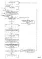
- the inventive methodis implemented according to the following steps 20-32 shown in FIG. 8 .
- the analog current signals I a , I b , I c of the alternating current that supplies the stator winding for at least one of the phases of the three phase asynchronous electric motor 1is measured using the current measuring devices 10, and/or at least one of the phases of the analog voltage signals U a , U b , U c supplying the three phase asynchronous electric motor 1 is measured using the voltage measuring devices 11.
- the measured analog electrical signals I a , I b , I c , U a , U b , U cwhich take the form of analog waveforms, are subsequently supplied to the signal conditioning unit 9. If an angular displacement transducer 5 is used in the electromechanical system 6 then an angular displacement signal ⁇ of the shaft 3 is measured and supplied to the signal conditioning unit 9.
- the measured analog electrical signals I a , I b , I c , U a , U b , U care converted to discrete electrical signals I aD , I bD , I cD , U aD , U bD , U cD , respectively.
- an angular displacement signal ⁇has been measured in step 20, then it is supplied to the signal conditioning unit 9 and converted to a discrete angular displacement signal ⁇ D .
- the signal conditioning unit 9which typically takes the form of an analog-to-digital converter is provided with a set of constant parameters P1, which characterize the process of converting the analog waveforms into the discrete signals, specifically the sampling rate F s and the length of the signal subjected to conversion T L .
- the sampling rate F swhich defines the number of samples taken per second, may take any value but a typical minimum rate is 1 kHz, and this is the default setting.
- the signal length T Ldefines the length of the measured analog electrical signals I aD , I bD , I cD , U aD , U bD , U cD , to which the analog-to-digital conversion is applied.
- the minimum value of the signal length T Lis 1 second.
- the other discrete electrical signals I bD , I cD , U aD , U bD , U cDmay also be described in an analogous way.
- the conversion processis well known in the art.
- the discrete electrical signals I aD , I bD , I cD , U aD , U bD , U cD , and if available, the discrete angular displacement signal ⁇ Dare automatically transmitted to the computer device 12 via the communication module 14 and stored in the data storage module 1 of the data processing unit 13.
- step 22the computer device 12 is supplied with a set of constant parameters P2 which are stored in the data storage module 15 of the data processing unit 13.
- the set of constant parameters P2consists of the desired number of averages to be performed M input , the number N of sampling points for every complete rotation of the shaft 3 of the electromechanical system 6, a warning threshold value X and a constant scaling factor Z.
- the constant scaling factor Zdescribes a relationship between the angular displacements of two interconnected shafts. For example and with reference to the two-stage reduction gearbox 2 of the exemplary embodiment, by setting the constant scaling factor Z to a value equal to the gear ratio between the gear connected to shaft 3 and a meshing gear on the lay shaft of the two-stage reduction gearbox 2 (not shown in FIG.
- the inventive methodit is possible to use the inventive method to diagnose the operating condition of components mounted on the lay shaft.
- the discrete electrical signals I aD , I bD , I cD , U aD , U bD , U cDare combined to form estimates of electromechanical system quantities such as current space phasors, voltage space phasors, the developed electromagnetic torque of the three phase asynchronous electric motor 1 or the developed electromagnetic flux of the three phase asynchronous electric motor 1.
- ⁇ D2 3 ⁇ I aD + e j ⁇ / 2 ⁇ ⁇ 3 ⁇ I bD + e j ⁇ / 2 ⁇ ⁇ 3 2 ⁇ I cD
- FIG. 2is a plot of the discrete stator current amplitude signal W D , in the time domain.
- W Dhas units of amperes, [A].
- the discrete current amplitude signal W D calculated in step 22is used in subsequent steps.
- step 23the presence of a discrete angular displacement signal ⁇ D within the data transmitted to the data storage module 15 of the data processing unit 13 is checked. If all necessary data i.e. the discrete current amplitude signal W D and the discrete angular displacement signal ⁇ D are present, then step 25 is carried out. If the discrete angular displacement signal ⁇ D is absent among the data transmitted to the data processing unit 13, then a process of calculating an estimation of the angular displacement ⁇ DEsT of the rotor of the three phase asynchronous electric motor 1 is carried out in step 24.
- step 24 in the data processing unit 13an estimation of the angular displacement O DEsT of the rotor of three phase asynchronous electric motor 1 is calculated on the basis of the discrete electrical signals I aD , I bD , I cD , U aD , U bD , U cD .
- Those who are skilled in the state of the artwill recognize that there are many ways of estimating the angular velocity of the rotor of an electrical rotating machine from measured electrical signals.
- Various methods of estimating the first time derivative of the electrical rotor angle of an electrical machineare described by Peter Vas in "Sensorless vector and direct torque control" (Oxford University Press, UK, 1998, ISBN 978-0-19-856465-2 ).
- An estimate of the mechanical angular displacement of the rotor of the electrical rotating machineis obtained by numerically integrating the first time derivative of the electrical rotor angle of the electrical machine using known methods, and then multiplying the resulting signal by the number of pole pairs of the three phase asynchronous electric motor 1. If necessary, the estimate of the mechanical angular displacement of the rotor of the electrical rotating machine is resampled using known methods, so that the resulting estimation of the angular displacement ⁇ DEst is synchronized to the discrete current amplitude signal W D .
- step 24the estimation of the angular displacement ⁇ DEst is used in subsequent steps.
- ⁇ D⁇ DEst and for simplification only the symbol of ⁇ D is used in describing the subsequent steps.
- a result of using this functionalityis that the methodology retains its attribute of being non-invasive.
- the constant scaling factor Zis taken from the constant parameter set P2 which is stored in the data storage module 15.
- the discrete angular displacement signal ⁇ Dis multiplied by the constant scaling factor Z.
- the result of multiplying the discrete angular displacement signal ⁇ D by the constant scaling factor Zis a scaled discrete angular displacement signal Z ⁇ D .
- the original discrete angular displacement signal ⁇ Dis shown in a time domain as a solid line, whilst the dashed line shows the scaled discrete angular displacement signal Z ⁇ D , where the constant scaling factor Z has a value which represents the output to input ratio of the gearbox 2.
- both the scaled discrete angular displacement signal Z ⁇ D and the discrete stator current amplitude signal W Dare comprised of values sampled at the same points in time, it is possible to synchronize the discrete current amplitude signal W D to the scaled discrete angular displacement signal Z ⁇ D .
- the discrete current amplitude signal W D versus angular displacement, ⁇ , in radiansas is shown in FIG. 4 .
- step 26 in the synchronous averaging module 16the discrete current amplitude signal Wp, which has been synchronized to the scaled discrete angular displacement signal Z ⁇ D is resampled at angular positions given in the resampling vector ⁇ R .
- this processrequires the desired number of averages to be performed M input by the user at step 22 to be less than the total number of completed rotations of the scaled discrete angular displacement signal Z ⁇ D . If the user has inserted a number greater than the total number of completed rotations of the scaled discrete angular displacement signal Z ⁇ D then the number of averages to be performed M is limited to the total number of completed rotations of the scaled discrete angular displacement signal Z ⁇ D in accordance with calculation (4).
- the resampling of the discrete current amplitude signal W D at the angular positions given in the resampling vector ⁇ Ris conducted using known techniques.
- the resampled discrete current amplitude signal Y Dis used in subsequent steps.
- the resampled discrete current amplitude signal Y Dis the result of resampling the discrete stator current amplitude signal W D at linear intervals of the scaled discrete angular displacement signal Z ⁇ D ;
- FIG. 6is a plot of the resampled discrete current amplitude signal Y D versus angular displacement, in radians with additional annotations detailing the process of dividing the resampled discrete current amplitude signal Yp into M intervals of equal length N.
- the synchronous average of the electrical signals Yis calculated.
- Y ⁇y ⁇ 1 ⁇ y ⁇ 2 ... y ⁇ N .
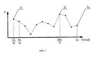
- FIG. 7is a plot of the synchronous average of the electrical signals Y versus angular displacement, in radians.
- the value of the kurtosis S of the synchronous average of the electrical signals Ygives a measure of the magnitude of large localized deviations in the synchronous average of the electrical signals Y , which can be caused by localized defects such as tooth cracking or pitting in gear teeth.
- Those skilled in the artwill appreciate that there are many different signal processing methodologies available for extracting information from the synchronous average of the electrical signals Y , ranging from time domain metrics, spectral analyses or time-frequency analyses which may be substituted for the kurtosis operation given within this step without significantly changing the scope of this invention.
- a warningis also indicated to the user via the output unit 17 in step 31.
- step 31the synchronous average of the electrical signals Y , the kurtosis S and the warning obtained in step 30 are automatically supplied to the user, via the output unit 18 using known methods.
- step 32the synchronous average of the electrical signals Y and the kurtosis S are automatically supplied to the user, via the output unit 18 using known methods. Additionally, the inventive method is restarted at step 20.
Landscapes
- Physics & Mathematics (AREA)
- General Physics & Mathematics (AREA)
- Engineering & Computer Science (AREA)
- Human Computer Interaction (AREA)
- Manufacturing & Machinery (AREA)
- Automation & Control Theory (AREA)
- Control Of Electric Motors In General (AREA)
- Control Of Ac Motors In General (AREA)
- Tests Of Circuit Breakers, Generators, And Electric Motors (AREA)
- Testing And Monitoring For Control Systems (AREA)
- Testing Of Devices, Machine Parts, Or Other Structures Thereof (AREA)
Abstract
Description
- The present invention is concerned with a method, an apparatus and a computer program for monitoring the condition of electromechanical systems in which electrical rotating machinery is used and in which at least one electrical signal is measured during an operation of the electromechanical system.
- Condition monitoring techniques are regularly based on the measurement and subsequent analysis of vibration signals measured using casing mounted vibration transducers, such as accelerometers. The main problems associated with using casing mounted vibration transducers relate to their mounting as the vibrations measured are dependent on the transmission path from the source of the vibration to the transducer. In some situations, subtle details in the vibration signal may be attenuated by the transmission path leading to missed indicators of diminished machine condition. These transmission path effects also mean that casing mounted vibration transducers are typically permanently fixed to the structure, as small changes in transducer position can result in different vibration signals being recorded. When the equipment is located in a hostile environment the performance of these transducers may degrade over time. Casing mounted vibration transducers are also particularly sensitive to environmental noise. Although casing mounted vibration transducers do not typically impede the normal functioning of a piece of equipment, in many cases special arrangements are required to mount them on a piece of equipment. For example, many vibration transducers are required to be mounted on flat surfaces, close to the source of the vibration. Furthermore, these transducers are typically unidirectional, and such multiple transducers are necessary to obtain enough information to make a confident decision regarding the condition of a piece of equipment.
- Electric motors and electric generators, or, more generally, electric rotating machines regularly form key parts of electromechanical systems. In recent years, the analysis of currents which may be measured from the power cables connecting the electrical rotating machines to the power source has been shown as a successful method for monitoring the condition of electromechanical systems. It has been shown that the currents that are induced in an electrical rotating machine change with operating conditions, often resulting in amplitude and phase modulations of large alternating current (AC) power supply currents. Changes in operating conditions related to defects such as broken rotor bars or rotor eccentricity may be related to the amplitude and frequency of modulations of the power supply currents. Motor current signature analysis (MCSA) involves analyzing measured current signals in the frequency domain, in order to diagnose and trend progressing defects. MCSA is attractive as it is relatively cheap to implement, and as the electric rotating machine forms part of the electromechanical system, the method may be thought of as nonintrusive. Primarily, MCSA has been used in the diagnosis of electric motor faults, though it has also been shown to react to changes in external loads, such as those caused by defects occurring in mechanical components such as bearings or gears.
- Usually the frequency spectrum of a measured current signal is dominated by the AC power supply current. The electric motor and the attached mechanical system forming electromechanical system, cause modulations of the AC power supply current resulting in sidebands appearing in the frequency spectrum. Hence, the dominant AC power supply current may be thought of as a carrier wave. It is rare that the power supply is ideal; phase and amplitude modulations of the AC power supply current unrelated to the operating condition of the machine can occur. This is especially true in electric drive systems where control action and pulse-width modulation will result in the power supply current carrier wave being a non-stationary waveform. Similarly, it is often the case that the load acting on an electrical rotating machine may be transient. The non-stationary nature of the power supply current carrier wave results in the components owing to the power supply appearing to be distributed over a range of frequencies. This can increase the difficulty in assessing the operating condition of an electromechanical system.
- From
US patent number 54830201, by Linehan et al - From US patent number
US 6993439 B2 by Grosjean , there is a known method of converting a measured current waveform from the time domain to the spatial domain. The angular displacement of the rotor of an electrical rotating machine is identified using a characteristic in a measured current waveform. For example, the amplitude modulations resulting from commutator switching may be used to estimate the position of the rotor of a DC motor. The current waveform is then normalized to this angular displacement and analyzed in the frequency domain, thus allowing electrical rotating machines which do not rotate at constant angular velocity to be analyzed in the frequency domain. - The prior art described above, gives methods of decreasing the variability of the frequency spectrum of measured current signals. However, even when considering an electromechanical system operating at a constant angular velocity and supplied by an idealized power supply, resulting in a stationary power supply current carrier wave, the amplitudes of modulation sidebands caused by operating conditions of the electromechanical system are low relative to the power supply current carrier wave and its harmonics. This is particularly true in the consideration of faults occurring in the mechanical system to which the electric machine is attached. Furthermore, insufficient resolution of transducers used to measure current signals can lead to harmonic distortion. As a result it can be difficult to distinguish components owing to the operating condition of the electromechanical system from other more dominant components or from the noise signals owing from transducer noise, ghost noise from non-constant sources or from transient vibrations occurring in the environment of the electric rotating machine.
- The present invention provides a method for monitoring the condition of an electromechanical system and an apparatus for implementing the method according to inventive method. The present invention provides also a computer program for monitoring the condition of electromechanical systems, which computer program is loadable in and executable on a data processing unit of a computer device and which computer program performs when being executed by the data processing unit of the computer device, the method according to claims 1-4.
- The presented invention has many advantages over existing methods of condition monitoring such as those described above. By using either measured angular displacement signals obtained from existing angular displacement transducers or, where these are unavailable, based on electric motor current-and voltage measurements, the system can be seen as non-invasive. Furthermore, the influence of issues related with the mounting of transducers, such as transmission path effects or the requirement of access to the elements of the electromechanical system is decreased.
- The measured electric motor current and voltage signals are synchronized to the angular displacement of a shaft of the electromechanical system before being resampled at discrete angular displacement values, within the range zero to two pi, which are determined by the user. Considering one such discrete angular displacement value of the shaft of the electromechanical system, and assuming that said shaft has completed more than one complete rotation, this preceding process will result in a series of electric motor current and/or voltage values all synchronized to that one, discrete angular displacement. The number of electric motor current and/or voltage values contained within this series will relate to the number of complete rotations of the shaft of the electromechanical system. By taking the average value of the series of electric motor current and/or voltage values synchronized to the discrete angular displacement value, the influence of noise and periodic components unrelated to the shaft to which the measured current and voltage signals have been synchronized can be decreased. By performing the same averaging operation for each of the considered discrete angular displacement values of the shaft of the electromechanical system, a synchronous average of electrical signals comprised of averaged electric motor current and/or voltage values occurring at each considered angular displacement value may be created. The synchronous average of electrical signals consists of components of the measured electric motor current and voltage signals which repeat periodically with each complete rotation of the shaft of the electromechanical system. As many changes in operating condition of a rotating mechanical system result in changes to the electric motor current and voltage signals that repeat from rotation to rotation, the resulting synchronous average of electrical signals will incorporate a lot of information for evaluating the condition of a machine. The invention also allows for the accurate condition monitoring of electromechanical machines even when the shaft of said machine does not rotate at a constant angular velocity.
- The presented invention is also advantageous relative to the previously described existing methods as it allows lower resolution transducers for measuring values of the electric motor current and voltage to be used. The measured electric motor current and voltage signals will be somewhat quantized due to transducer resolution. Transducer quantization level results in a digital signal with limited resolution being recorded. Consider once again the series of electric motor current and/or voltage values that have all been synchronized to one, discrete angular displacement value. As previously discussed, the number of electric motor current and/or voltage values that comprise the series will relate to the number of complete rotations of the shaft of the electromechanical system. It is assumed that the measurable electric motor current and voltage signals consist of an underlying signal, containing information pertaining the operating condition of the electromechanical system, superposed with naturally occurring noise, which may be described by a zero mean Gaussian function. As the number of complete rotations of the shaft of the electromechanical system tends to infinity, the proportion of measured motor current and/or voltage values recorded at discrete levels above the underlying signal to those recorded at discrete levels below the underlying signal will be equal to the proportion of distances between the two discrete transducer levels and the underlying value. Hence, by performing the operation described previously, the resulting averaged value will tend to the underlying value as the number of complete rotations tends to infinity. Thus, extending this result to all of the considered discrete angular displacement values of the shaft of the electromechanical system, the output synchronous average of electrical signals will tend to the underlying signal, containing information pertaining the operating condition of the electromechanical system, which repeats periodically with each complete rotation of the shaft of the electromechanical system. As a result of this increase in accuracy, and the associated decrease in the influence of noise, the presented invention is more sensitive to small changes in the operating condition of an electromechanical machine than existing current analysis inventions.
FIG. 1 is a picture of a electromechanical compressor system together with schematic view of the apparatus which may be used in the implementation of the present invention;FIG. 2 is a plot of the discrete stator current amplitude signal WD, in the time domain (WD has units of amperes [A]);FIG. 3 is a plot of a discrete angular displacement signal θD and a scaled discrete angular displacement signal Z·θD, in radians, versus time;FIG. 4 is a plot of the discrete stator current amplitude signal WD, versus angular displacement, in radians, what is achieved by synchronizing the discrete stator current amplitude signal WD to the scaled discrete angular displacement signal Z·θD;FIG. 5 is a plot of a resampled discrete current amplitude signal YD versus angular displacement, in radians.FIG. 6 is a plot of the resampled discrete current amplitude signal YD versus angular displacement, in radians with additional annotations detailing the process of dividing the resampled discrete current amplitude signal YD into M intervals of equal length N;FIG. 7 is a plot of the synchronous average of the electrical signalsY versus angular displacement, in radians;FIG. 8 presents a diagram of operations performed for condition monitoring of the electromechanical system in accordance with the present invention.- Referring to
FIG. 1 , an example application of the present invention and the apparatus of this invention for diagnosing the operating condition of an electromechanical compressor system is presented. A three phase asynchronouselectric motor 1 is used to drive a two-stage reduction gearbox 2. The output of the gearbox is connected via ashaft 3 to acompressor 4. Mounted on theshaft 3 is anangular displacement transducer 5, which can be used to measure the angular displacement of the shaft. A sensor, or a group of sensors that are capable of measuring speeds or accelerations of theshaft 3, not presented in the drawing, may be used in place of theangular displacement transducer 5. In applications where it is important to track angular displacements, speeds or accelerations, such as in compressors, it is regular to instrument a system with transducers which convert angular positions into either analog or digital electronic signals. The three phase asynchronouselectric motor 1, the two-stage reduction gearbox 2, theshaft 3, and thecompressor 4 and, if present, anangular displacement transducer 5 together comprise theelectromechanical system 6. If anangular displacement transducer 5 or sensor does indeed form part of theelectromechanical system 6, then it is utilized in the application of the presented invention. However, it is also possible to apply the invention if such a transducer ofsensor 5 does not form part of theelectromechanical system 6. The electricpower supply device 7 provides three-phase alternating current to the asynchronouselectric motor 1 by way ofpower supply cables 8. The angular displacement transducer 5 (if present) is connected to one of the inputs to thesignal conditioning unit 9. One or more outputs ofcurrent measuring devices 10, and/orvoltage measuring devices 11 are connected with other inputs of thesignal conditioning unit 9. Thecurrent measuring devices 10 and thevoltage measuring devices 11 are connected with each of the phases a, b, c of the electricpower supply device 7. Thesignal conditioning unit 9 is connected to acomputer device 12, with adata processing unit 13 andcommunication module 14. In the data processing unit 13 adata storage module 15 and asynchronous averaging module 16 are implemented. Some other modules which are necessary for processing and calculating data, not presented in the drawing, are also implemented in the processor. Furthermore, thecomputer device 12 contains memories RAM and ROM, which are also not presented in the drawing. Thecomputer device 12 is connected to anoutput unit 17 in which the results of the condition monitoring are presented to the user. Theoutput unit 17 could be a monitor, a printer or any useful device for presentation of the results of the invention. - The inventive method is implemented according to the following steps 20-32 shown in
FIG. 8 . - With reference to the electromechanical network shown in
FIG. 1 instep 20 the analog current signals Ia, Ib, Ic of the alternating current that supplies the stator winding for at least one of the phases of the three phase asynchronouselectric motor 1 is measured using thecurrent measuring devices 10, and/or at least one of the phases of the analog voltage signals Ua, Ub, Uc supplying the three phase asynchronouselectric motor 1 is measured using thevoltage measuring devices 11. The measured analog electrical signals Ia, Ib, Ic, Ua, Ub, Uc, which take the form of analog waveforms, are subsequently supplied to thesignal conditioning unit 9. If anangular displacement transducer 5 is used in theelectromechanical system 6 then an angular displacement signal θ of theshaft 3 is measured and supplied to thesignal conditioning unit 9. - In the
next step 21 the measured analog electrical signals Ia, Ib, Ic, Ua, Ub, Uc, are converted to discrete electrical signals IaD, IbD, IcD, UaD, UbD, UcD, respectively. Additionally, if an angular displacement signal θ has been measured instep 20, then it is supplied to thesignal conditioning unit 9 and converted to a discrete angular displacement signal θD. Thesignal conditioning unit 9, which typically takes the form of an analog-to-digital converter is provided with a set of constant parameters P1, which characterize the process of converting the analog waveforms into the discrete signals, specifically the sampling rate Fs and the length of the signal subjected to conversion TL. The sampling rate Fs, which defines the number of samples taken per second, may take any value but a typical minimum rate is 1 kHz, and this is the default setting. The signal length TL, defines the length of the measured analog electrical signals IaD, IbD, IcD, UaD, UbD, UcD, to which the analog-to-digital conversion is applied. In the embodiment of the inventive method, the minimum value of the signal length TL is 1 second. Considering the discrete current signal of the phases of the three phase asynchronouselectric motor 1, IaD consists of the current value iak of k consecutive samples, ranging from the first sample, k = 1, to k = L, L being the number of samples contained in the signal. The other discrete electrical signals IbD, IcD, UaD, UbD, UcD may also be described in an analogous way. If an angular displacement signal θ has been supplied to thesignal conditioning unit 9 it is converted into the discrete angular displacement signal θD, which consists of the angular displacement value θk of k consecutive samples ranging from the first sample, k = 1, to k = L. The conversion process is well known in the art. The discrete electrical signals IaD, IbD, IcD, UaD, UbD, UcD, and if available, the discrete angular displacement signal θD are automatically transmitted to thecomputer device 12 via thecommunication module 14 and stored in thedata storage module 1 of thedata processing unit 13. - In
step 22 thecomputer device 12 is supplied with a set of constant parameters P2 which are stored in thedata storage module 15 of thedata processing unit 13. The set of constant parameters P2 consists of the desired number of averages to be performed Minput, the number N of sampling points for every complete rotation of theshaft 3 of theelectromechanical system 6, a warning threshold value X and a constant scaling factor Z. In many cases the constant scaling factor Z describes a relationship between the angular displacements of two interconnected shafts. For example and with reference to the two-stage reduction gearbox 2 of the exemplary embodiment, by setting the constant scaling factor Z to a value equal to the gear ratio between the gear connected toshaft 3 and a meshing gear on the lay shaft of the two-stage reduction gearbox 2 (not shown inFIG. 1 ) it is possible to use the inventive method to diagnose the operating condition of components mounted on the lay shaft. In thedata processing unit 13 of thecomputer device 12 the discrete electrical signals IaD, IbD, IcD, UaD, UbD, UcD are combined to form estimates of electromechanical system quantities such as current space phasors, voltage space phasors, the developed electromagnetic torque of the three phase asynchronouselectric motor 1 or the developed electromagnetic flux of the three phase asynchronouselectric motor 1. In the exemplary embodiment of the invention only the discrete current signals IaD, IbD, IcD, are combined to form a discrete complex stator current space phasor signal ΨD according to the formula:
- The absolute value of the discrete complex stator current space phasor signal ΨD forms a discrete stator current amplitude signal WD, given as:

FIG. 2 is a plot of the discrete stator current amplitude signal WD, in the time domain. As a consequence of being formed of the discrete electrical signals IaD, IbD, IcD, UaD, UbD, UcD, the discrete current amplitude signal WD consists of the stator current amplitude value Wk of k consecutive samples ranging from the first sample, k = 1, to k = L, L being the sample length. In the described embodiment WD has units of amperes, [A]. Those skilled in the state of the art will recognize that there are various electromechanical system quantities which may be estimated using discrete electrical signals IaD, IbD, IcD, UaD, UbD, UcD and that it is to be understood that the discrete stator current amplitude signal WD, which is used in subsequent steps could be replaced by other estimates of electromechanical system quantities without departing from the scope of the invention as defined in the claims. If parameters of the three phase asynchronouselectric motor 1 are required in the estimation of certain electromechanical system quantities then these are included in the set of constant parameters P2 which are supplied to thecomputer device 12 and stored in thedata storage module 15 of thedata processing unit 13. Returning to the exemplary embodiment, in addition to the discrete electrical signals IaD, IbD, IcD, UaD, UbD, UcD and, if available, the discrete angular displacement signal θD, the discrete current amplitude signal WD calculated instep 22 is used in subsequent steps.- In
step 23 the presence of a discrete angular displacement signal θD within the data transmitted to thedata storage module 15 of thedata processing unit 13 is checked. If all necessary data i.e. the discrete current amplitude signal WD and the discrete angular displacement signal θD are present, then step 25 is carried out. If the discrete angular displacement signal θD is absent among the data transmitted to thedata processing unit 13, then a process of calculating an estimation of the angular displacement θDEsT of the rotor of the three phase asynchronouselectric motor 1 is carried out instep 24. - In
step 24 in thedata processing unit 13 an estimation of the angular displacement ODEsT of the rotor of three phase asynchronouselectric motor 1 is calculated on the basis of the discrete electrical signals IaD, IbD, IcD, UaD, UbD, UcD. Those who are skilled in the state of the art will recognize that there are many ways of estimating the angular velocity of the rotor of an electrical rotating machine from measured electrical signals. Various methods of estimating the first time derivative of the electrical rotor angle of an electrical machine are described byPeter Vas in "Sensorless vector and direct torque control" (Oxford University Press, UK, 1998, ISBN 978-0-19-856465-2). An estimate of the mechanical angular displacement of the rotor of the electrical rotating machine is obtained by numerically integrating the first time derivative of the electrical rotor angle of the electrical machine using known methods, and then multiplying the resulting signal by the number of pole pairs of the three phase asynchronouselectric motor 1. If necessary, the estimate of the mechanical angular displacement of the rotor of the electrical rotating machine is resampled using known methods, so that the resulting estimation of the angular displacement θDEst is synchronized to the discrete current amplitude signal WD. θDEst consists of the estimated angular displacement value θkEst of k consecutive samples ranging from the first sample, k = 1, to k = L. Ifstep 24 is enacted then the estimation of the angular displacement θDEst is used in subsequent steps. As such estimated data is very similar to an equivalently measured data, it is convenient to assume that θD = θDEst and for simplification only the symbol of θD is used in describing the subsequent steps. A result of using this functionality is that the methodology retains its attribute of being non-invasive. - At
step 25 in thesynchronous averaging module 16 the constant scaling factor Z is taken from the constant parameter set P2 which is stored in thedata storage module 15. The discrete angular displacement signal θD is multiplied by the constant scaling factor Z. The result of multiplying the discrete angular displacement signal θD by the constant scaling factor Z is a scaled discrete angular displacement signal Z·θD. Z·θD consists of the estimated angular displacement value Z·0k, of k consecutive samples ranging from the first sample, k = 1, to k = L. InFIG. 3 the original discrete angular displacement signal θD is shown in a time domain as a solid line, whilst the dashed line shows the scaled discrete angular displacement signal Z·θD, where the constant scaling factor Z has a value which represents the output to input ratio of thegearbox 2. - As both the scaled discrete angular displacement signal Z·θD and the discrete stator current amplitude signal WD are comprised of values sampled at the same points in time, it is possible to synchronize the discrete current amplitude signal WD to the scaled discrete angular displacement signal Z·θD. Hence it is possible to show the discrete current amplitude signal WD versus angular displacement, θ, in radians as is shown in
FIG. 4 . Instep 26 in thesynchronous averaging module 16 the discrete current amplitude signal Wp, which has been synchronized to the scaled discrete angular displacement signal Z·θD is resampled at angular positions given in the resampling vector θR. The resampling vector θR consists of the angular displacement values θR,p given as
where M is the number of averages to be performed is obtained from the calculation:
where the number of averages to be performed M and the number N of sampling points for every complete rotation of theshaft 3 of theelectromechanical system 6 are taken from the constant parameter set P2 which is stored in thedata storage module 15. Note that this process requires the desired number of averages to be performed Minput by the user atstep 22 to be less than the total number of completed rotations of the scaled discrete angular displacement signal Z ·θD. If the user has inserted a number greater than the total number of completed rotations of the scaled discrete angular displacement signal Z·θD then the number of averages to be performed M is limited to the total number of completed rotations of the scaled discrete angular displacement signal Z·θD in accordance with calculation (4). The resampling of the discrete current amplitude signal WD at the angular positions given in the resampling vector θR is conducted using known techniques. The resulting resampled discrete current amplitude signal YD consists of resampled stator current amplitude values yp at p consecutive samples ranging from the first sample, p = 1, to p = M·N, M being the number of averages to be performed and N being the number of sampling points for every complete rotation. The resampled discrete current amplitude signal YD is used in subsequent steps. AtFig.5 the resampled discrete current amplitude signal YD is the result of resampling the discrete stator current amplitude signal WD at linear intervals of the scaled discrete angular displacement signal Z·θD; - In
step 27, in thesynchronous averaging module 16, the resampled discrete current amplitude signal YD is divided into M consecutive intervals, each containing N consecutive samples, thus allowing the resampled stator current amplitude values yp to be written as ym,n, where n are the consecutive samples ranging from, n = 1, to n = N and m are the consecutive intervals ranging from, m = 1, to m = M.FIG. 6 is a plot of the resampled discrete current amplitude signal YD versus angular displacement, in radians with additional annotations detailing the process of dividing the resampled discrete current amplitude signal Yp into M intervals of equal length N. - At step 28 in the
synchronous averaging module 16, the synchronous average of the electrical signalsY is calculated. The synchronous average of the electrical signalsY , consists of n averaged values of the electrical signalsy n calculated using:
- Hence the synchronous average of the electrical signals
Y may be calculated as:
- The synchronous average of the electrical signals
Y is sampled at linear angular displacement intervals in the range zero to two π according to the calculation:
where θn is the discrete angular displacement value at sampling point n.FIG. 7 is a plot of the synchronous average of the electrical signalsY versus angular displacement, in radians. - In
step 29 in thesynchronous averaging module 16, a kurtosis S of the synchronous average of the electrical signalsY is calculated according to formula:
- The value of the kurtosis S of the synchronous average of the electrical signals
Y , gives a measure of the magnitude of large localized deviations in the synchronous average of the electrical signalsY , which can be caused by localized defects such as tooth cracking or pitting in gear teeth. Those skilled in the art will appreciate that there are many different signal processing methodologies available for extracting information from the synchronous average of the electrical signalsY , ranging from time domain metrics, spectral analyses or time-frequency analyses which may be substituted for the kurtosis operation given within this step without significantly changing the scope of this invention. - In
step 30 in thesynchronous averaging module 16, the threshold value X is taken from the constant parameter set P2 which is stored in thedata storage module 15. A typical value for the threshold value X = 3.5. If the value of the kurtosis S of the synchronous average of the electrical signals is below the threshold value X, then the kurtosis S of the synchronous average of the electrical signals, as well as the synchronous average of the electrical signalsY is indicated to the user via theoutput unit 17 instep 32. If the value of the kurtosis S of the synchronous average of the electrical signals is above the threshold value X, then in addition to the kurtosis S of the synchronous average of the electrical signals and the synchronous average of the electrical signalsY , a warning is also indicated to the user via theoutput unit 17 instep 31. - At
step 31 the synchronous average of the electrical signalsY , the kurtosis S and the warning obtained instep 30 are automatically supplied to the user, via the output unit 18 using known methods. - At
step 32 the synchronous average of the electrical signalsY and the kurtosis S are automatically supplied to the user, via the output unit 18 using known methods. Additionally, the inventive method is restarted atstep 20. Letter Name a, b, c phases of the electric power supply device Ia, Ib, Ic analog current signals Ua, Ub, Uc analog voltage signals Θ angular displacement signal IaD, IbD, IcD, UaD, discrete electrical signals UbD, UcD θD discrete angular displacement signal P1 constant parameters which characterize the process of converting the analog waveforms into the discrete signals Fs sampling rate TL the length of the signal subjected to conversion ia,k current value at sampling point k L the number of samples contained in the signal θk angular displacement value at sampling point k P2 a set of constant parameters supplied to the computer device 12 Minput the desired number of averages to be performed N the number of sampling points for every complete rotation of the shaft 3 ofthe electromechanical system X the warning threshold value Z constant scaling factor ΨD discrete complex stator current space phasor signal WD the discrete stator current amplitude signal Wk the stator current amplitude value at sampling point k A Amperes (units of WD) θDEst estimation of the angular displacement of the rotor of the three phase asynchronous electric motor 1θkEst the estimated angular displacement value at sampling point k Z·θD scaled discrete angular displacement signal. Z·θk, estimated angular displacement value at sampling point k θR resampling vector θR,p the angular displacement values (which comprise the Resampling vector θR) at sampling point p M the number of averages to be performed YD resampled discrete current amplitude signal yp resampled stator current amplitude values at sampling point p ym,n resampled stator current amplitude values at sampling point n in interval m Y the synchronous average of the electrical signals y naveraged values of the electrical signals at sampling point n S kurtosis of the synchronous average of the electrical signals Y


Claims (6)
- A method for monitoring the condition of an electromechanical system comprising the steps of:measuring current and/or voltage signals of an electromechanical system,measuring an angular position of a rotating shaft of interest of the electromechanical systems or estimating the value of discrete angular position of a rotating shaft of interest of the electromechanical system,synchronizing the current and/or voltage signals to the scaled angular displacement of the rotating shaft,dividing the synchronous electrical signals into intervals corresponding to each completed rotation of the rotating shaft,averaging a number of intervals of synchronous electrical signals to obtain as average synchronous electrical signal,extracting characteristic data of the magnitude from the values of the average synchronous electrical signal,comparing the extracted characteristic data of the magnitude with a threshold which is given as a limit,indicating an alarm to the user when the limit is exceed.
- A method according to claim 1, wherein the averaging of M intervals of synchronous electrical signals corresponding to M complete rotations, in order to obtain a synchronous average of the electrical signals (
Y ), consisting of M averaged values of the electrical signalsy n is calculated from the formula
where ym,n is the synchronous electrical signal values at sampling point n in interval m, N is a number of sampling points for every complete rotation of the shaft of the electromechanical system, M is a number of averages to be performed. - A method according to any previous claims, wherein the kurtosis S of the synchronous average of the electrical signals represents the characteristic data of the magnitude from the values of the average synchronous electrical signal and is calculated according to the formula:

- An apparatus for implementing the method according to claims 1-4 comprising:means for measuring current and/or voltage signals of an electromechanical system,means for measuring an angular position of a rotating shaft of interest of the electromechanical systems or means for estimating the value of discrete angular position of a rotating shaft of interest of the electromechanical system,means for synchronizing current and/or voltage signals to a scaled angular displacement of the rotating shaft,means for dividing the synchronous electrical signals into intervals corresponding to each completed rotation of the rotating shaft,means for averaging a number of intervals of synchronous electrical signals,means for extracting from the values of the average synchronous electrical signals, a characteristic data of the magnitude, and comparing the extracted characteristic data of the magnitude with a threshold which is given as a limit,means for comparing the extracted characteristic data of the magnitude with a threshold which is given as a limit,means for indicating an alarm to the user when the limit is exceed.
- An apparatus according to claim 4 wherein means for synchronizing current and/or voltage signals to a scaled angular displacement of the rotating shaft, means for dividing the synchronous electrical signals into intervals corresponding to each completed rotation of the rotating shaft, means for averaging a number of intervals of synchronous electrical signals, means for extracting from the values of the average synchronous electrical signals, a characteristic data of the magnitude, and comparing the extracted characteristic data of the magnitude with a threshold which is given as a limit are implemented in a synchronous averaging module (16) of a computer device (12).
- A computer program for monitoring the condition of electromechanical systems, which computer program is loadable in and executable on a data processing unit (13) of a computer device (12) and which computer program performs when being executed by the data processing unit of the computer device, the method according to claims 1-4.


Priority Applications (10)
| Application Number | Priority Date | Filing Date | Title |
|---|---|---|---|
| EP11460026.5AEP2523009B1 (en) | 2011-05-12 | 2011-05-12 | Method and apparatus for monitoring the condition of electromechanical systems |
| DK11460026TDK2523009T3 (en) | 2011-05-12 | 2011-05-12 | Method and device for monitoring the state afelektromekaniske systems |
| US14/115,912US9459088B2 (en) | 2011-05-12 | 2012-03-21 | Method and apparatus for monitoring the condition of electromechanical systems |
| CN201280022882.0ACN103502827B (en) | 2011-05-12 | 2012-03-21 | Condition method and apparatus for monitoring electromechanical systems |
| CA2828268ACA2828268C (en) | 2011-05-12 | 2012-03-21 | Method and apparatus for monitoring the condition of electromechanical systems |
| BR112013029141-9ABR112013029141B1 (en) | 2011-05-12 | 2012-03-21 | method, device and algorithm for monitoring the condition of an electromechanical system |
| PCT/EP2012/001233WO2012152353A1 (en) | 2011-05-12 | 2012-03-21 | Method and apparatus for monitoring the condition of electromechanical systems |
| AU2012252901AAU2012252901B2 (en) | 2011-05-12 | 2012-03-21 | Method and apparatus for monitoring the condition of electromechanical systems |
| JP2014509619AJP5932022B2 (en) | 2011-05-12 | 2012-03-21 | Method and apparatus for monitoring the state of an electromechanical system |
| ZA2013/07503AZA201307503B (en) | 2011-05-12 | 2013-10-08 | Method and apparatus for monitoring the condition of electromechanical systems |
Applications Claiming Priority (1)
| Application Number | Priority Date | Filing Date | Title |
|---|---|---|---|
| EP11460026.5AEP2523009B1 (en) | 2011-05-12 | 2011-05-12 | Method and apparatus for monitoring the condition of electromechanical systems |
Publications (2)
| Publication Number | Publication Date |
|---|---|
| EP2523009A1true EP2523009A1 (en) | 2012-11-14 |
| EP2523009B1 EP2523009B1 (en) | 2015-01-28 |
Family
ID=45937197
Family Applications (1)
| Application Number | Title | Priority Date | Filing Date |
|---|---|---|---|
| EP11460026.5AActiveEP2523009B1 (en) | 2011-05-12 | 2011-05-12 | Method and apparatus for monitoring the condition of electromechanical systems |
Country Status (10)
| Country | Link |
|---|---|
| US (1) | US9459088B2 (en) |
| EP (1) | EP2523009B1 (en) |
| JP (1) | JP5932022B2 (en) |
| CN (1) | CN103502827B (en) |
| AU (1) | AU2012252901B2 (en) |
| BR (1) | BR112013029141B1 (en) |
| CA (1) | CA2828268C (en) |
| DK (1) | DK2523009T3 (en) |
| WO (1) | WO2012152353A1 (en) |
| ZA (1) | ZA201307503B (en) |
Cited By (12)
| Publication number | Priority date | Publication date | Assignee | Title |
|---|---|---|---|---|
| WO2014193732A3 (en)* | 2013-05-30 | 2015-02-19 | Lockheed Martin Corporation | Mechanisms for deriving an accurate timing signal from a noisy waveform |
| EP3255776A1 (en)* | 2016-06-07 | 2017-12-13 | ABB Technology AG | A method and device for determination of a torsional deflection of a rotation shaft in the electromechanical drivetrain |
| GB2551112A (en)* | 2016-05-25 | 2017-12-13 | Ge Aviat Systems Ltd | Aircraft component monitoring system |
| CN107478985A (en)* | 2017-08-21 | 2017-12-15 | 河海大学常州校区 | On-load tap changers of transformers state on_line monitoring device and its monitoring method |
| CN109270364A (en)* | 2017-07-18 | 2019-01-25 | 中国科学院理化技术研究所 | Compressor parameter online detection method |
| US10403116B2 (en) | 2017-06-20 | 2019-09-03 | General Electric Company | Electrical signature analysis of electrical rotating machines |
| CN110275108A (en)* | 2018-03-16 | 2019-09-24 | 中国石油天然气股份有限公司 | Linear motor detection system and method |
| KR20200005613A (en)* | 2017-09-29 | 2020-01-15 | 가부시키가이샤 히다치 산키시스템 | Data acquisition method, inverters and rotary electric machines |
| CN110702433A (en)* | 2018-06-21 | 2020-01-17 | 张广舜 | Electromechanical testing device |
| RU2711647C1 (en)* | 2019-04-08 | 2020-01-17 | ОАО "Научно-исследовательский институт технологии, контроля и диагностики железнодорожного транспорта" (ОАО "НИИТКД") | Device and method for evaluation of technical condition of asynchronous motors |
| US10658961B2 (en) | 2015-10-20 | 2020-05-19 | Abb Schweiz Ag | Method for identifying the discrete instantaneous angular speed of an electromechanical system |
| US10928814B2 (en) | 2017-02-24 | 2021-02-23 | General Electric Technology Gmbh | Autonomous procedure for monitoring and diagnostics of machine based on electrical signature analysis |
Families Citing this family (18)
| Publication number | Priority date | Publication date | Assignee | Title |
|---|---|---|---|---|
| EP2574947A1 (en)* | 2011-09-30 | 2013-04-03 | ABB Technology AG | A method of determining stationary signals for the diagnostics of an electromechanical system |
| CN103995229B (en)* | 2014-05-21 | 2016-06-22 | 浙江工业大学 | A kind of feature based chooses the motor health monitoring with mahalanobis distance and abnormality diagnostic method |
| US9431945B2 (en)* | 2014-09-24 | 2016-08-30 | Texas Instruments Incorporated | Normalization of motor phase measurements |
| US9791343B2 (en)* | 2015-02-12 | 2017-10-17 | General Electric Company | Methods and systems to derive engine component health using total harmonic distortion in a knock sensor signal |
| US9618583B2 (en)* | 2015-03-10 | 2017-04-11 | Mitsubishi Electric Research Laboratories, Inc | Fault detection in induction motors based on current signature analysis |
| JP6979620B2 (en)* | 2016-05-09 | 2021-12-15 | パナソニックIpマネジメント株式会社 | Power generation equipment monitoring system, power generation equipment monitoring method, and program |
| CN106769024A (en)* | 2017-03-02 | 2017-05-31 | 哈尔滨理工大学 | Gear Fault Diagnosis device based on asynchronous motor stator current method |
| US20210126570A1 (en)* | 2017-04-13 | 2021-04-29 | Janardhana Swamy | Electric driver control system and method thereof |
| WO2019147750A2 (en)* | 2018-01-24 | 2019-08-01 | Magnetic Pumping Solutions, Llc | Method and system for monitoring the condition of rotating systems |
| CN113015917B (en)* | 2018-11-20 | 2024-04-16 | 三菱电机株式会社 | Remaining life diagnosis method of rotating electrical machine and remaining life diagnosis device of rotating electrical machine |
| CN110844111B (en)* | 2019-10-11 | 2022-11-04 | 中国直升机设计研究所 | Multi-characteristic index bevel gear health state assessment method |
| US11485476B2 (en)* | 2019-10-25 | 2022-11-01 | Hamilton Sundstrand Corporation | Driveline torque monitoring for long-term health assessment |
| DE102020122011A1 (en) | 2020-08-24 | 2022-02-24 | Bayerische Motoren Werke Aktiengesellschaft | Procedure for testing transmissions, transmission test bench and use |
| CN112147950B (en)* | 2020-09-17 | 2021-07-13 | 成都航空职业技术学院 | Numerical control side milling system and accurate synchronization method of threshold value and signal to be monitored thereof |
| JP7596780B2 (en)* | 2020-12-24 | 2024-12-10 | 富士電機株式会社 | Power conversion device, power transmission device, information processing device, and degradation/abnormality diagnosis method |
| CN112709690B (en)* | 2021-01-04 | 2023-01-31 | 北京昊鹏智能技术有限公司 | Method, apparatus, device and medium for detecting fault of electrically driven compressor system |
| JP7627192B2 (en)* | 2021-09-03 | 2025-02-05 | 株式会社日立製作所 | Transmission Monitoring System |
| CN114264953B (en)* | 2021-12-01 | 2024-05-24 | 珠海格力电器股份有限公司 | Permanent magnet synchronous motor demagnetizing fault diagnosis method and system and diagnosis device |
Citations (16)
| Publication number | Priority date | Publication date | Assignee | Title |
|---|---|---|---|---|
| US4303882A (en)* | 1979-10-19 | 1981-12-01 | General Electric Company | Method and apparatus for monitoring torsional vibration in the rotor of a dynamoelectric machine |
| US4926105A (en)* | 1987-02-13 | 1990-05-15 | Mischenko Vladislav A | Method of induction motor control and electric drive realizing this method |
| US4978909A (en)* | 1988-11-14 | 1990-12-18 | Martin Marietta Energy Systems, Inc. | Demodulation circuit for AC motor current spectral analysis |
| EP0632283A1 (en)* | 1993-06-29 | 1995-01-04 | Liberty Technologies, Inc. | Method and apparatus for analysis of polyphase electrical motor systems |
| US5461329A (en)* | 1992-01-21 | 1995-10-24 | Martin Marietta Energy Systems, Inc. | Method and apparatus for generating motor current spectra to enhance motor system fault detection |
| US5483201A (en) | 1993-09-30 | 1996-01-09 | At&T Corp. | Synchronization circuit using a high speed digital slip counter |
| US5519337A (en)* | 1993-11-04 | 1996-05-21 | Martin Marietta Energy Systems, Inc. | Motor monitoring method and apparatus using high frequency current components |
| US5523701A (en)* | 1994-06-21 | 1996-06-04 | Martin Marietta Energy Systems, Inc. | Method and apparatus for monitoring machine performance |
| US5832414A (en)* | 1995-12-18 | 1998-11-03 | Abb Power T&D Company Inc. | Generator protection system and method of compensating for errors in phasor estimation due to oscillations in discrete Fourier transform |
| EP1283594A1 (en)* | 2000-04-18 | 2003-02-12 | Toyota Jidosha Kabushiki Kaisha | Motor controller |
| US20030042861A1 (en)* | 2001-06-11 | 2003-03-06 | Elia Schwartz | System and method for predicting mechanical failures in machinery driven by an induction motor |
| US20040050177A1 (en)* | 2002-09-13 | 2004-03-18 | Grosjean Dennis Francis | Motor based condition monitoring |
| US20040169482A1 (en)* | 2002-02-25 | 2004-09-02 | Toshiyuki Maeda | Motor control method and its apparatus |
| EP1681762A2 (en)* | 2005-01-13 | 2006-07-19 | Hitachi, Ltd. | Synchronous motor driving system and method |
| US20090091289A1 (en)* | 2007-10-08 | 2009-04-09 | University Of Victoria Innovation And Development Corporation | Stator inter-turn fault detection of synchronous machines |
| EP2197104A1 (en)* | 2007-09-27 | 2010-06-16 | Mitsubishi Electric Corporation | Controller of rotary electric machine |
Family Cites Families (5)
| Publication number | Priority date | Publication date | Assignee | Title |
|---|---|---|---|---|
| US5365787A (en)* | 1991-10-02 | 1994-11-22 | Monitoring Technology Corp. | Noninvasive method and apparatus for determining resonance information for rotating machinery components and for anticipating component failure from changes therein |
| US5452223A (en)* | 1993-08-20 | 1995-09-19 | Eaton Corporation | Arc detection using current variation |
| US5483020A (en) | 1994-04-12 | 1996-01-09 | W. L. Gore & Associates, Inc. | Twin-ax cable |
| CN100543440C (en)* | 2007-03-28 | 2009-09-23 | 华北电力大学 | Failure testing method of asynchronous motor bearing |
| ITBO20070619A1 (en)* | 2007-09-12 | 2009-03-13 | Spal Automotive Srl | ELECTRIC DRIVE AND PILOT METHOD OF THE SAME. |
- 2011
- 2011-05-12DKDK11460026Tpatent/DK2523009T3/enactive
- 2011-05-12EPEP11460026.5Apatent/EP2523009B1/enactiveActive
- 2012
- 2012-03-21WOPCT/EP2012/001233patent/WO2012152353A1/enactiveApplication Filing
- 2012-03-21AUAU2012252901Apatent/AU2012252901B2/enactiveActive
- 2012-03-21USUS14/115,912patent/US9459088B2/enactiveActive
- 2012-03-21CACA2828268Apatent/CA2828268C/enactiveActive
- 2012-03-21BRBR112013029141-9Apatent/BR112013029141B1/enactiveIP Right Grant
- 2012-03-21CNCN201280022882.0Apatent/CN103502827B/enactiveActive
- 2012-03-21JPJP2014509619Apatent/JP5932022B2/enactiveActive
- 2013
- 2013-10-08ZAZA2013/07503Apatent/ZA201307503B/enunknown
Patent Citations (17)
| Publication number | Priority date | Publication date | Assignee | Title |
|---|---|---|---|---|
| US4303882A (en)* | 1979-10-19 | 1981-12-01 | General Electric Company | Method and apparatus for monitoring torsional vibration in the rotor of a dynamoelectric machine |
| US4926105A (en)* | 1987-02-13 | 1990-05-15 | Mischenko Vladislav A | Method of induction motor control and electric drive realizing this method |
| US4978909A (en)* | 1988-11-14 | 1990-12-18 | Martin Marietta Energy Systems, Inc. | Demodulation circuit for AC motor current spectral analysis |
| US5461329A (en)* | 1992-01-21 | 1995-10-24 | Martin Marietta Energy Systems, Inc. | Method and apparatus for generating motor current spectra to enhance motor system fault detection |
| EP0632283A1 (en)* | 1993-06-29 | 1995-01-04 | Liberty Technologies, Inc. | Method and apparatus for analysis of polyphase electrical motor systems |
| US5483201A (en) | 1993-09-30 | 1996-01-09 | At&T Corp. | Synchronization circuit using a high speed digital slip counter |
| US5519337A (en)* | 1993-11-04 | 1996-05-21 | Martin Marietta Energy Systems, Inc. | Motor monitoring method and apparatus using high frequency current components |
| US5523701A (en)* | 1994-06-21 | 1996-06-04 | Martin Marietta Energy Systems, Inc. | Method and apparatus for monitoring machine performance |
| US5832414A (en)* | 1995-12-18 | 1998-11-03 | Abb Power T&D Company Inc. | Generator protection system and method of compensating for errors in phasor estimation due to oscillations in discrete Fourier transform |
| EP1283594A1 (en)* | 2000-04-18 | 2003-02-12 | Toyota Jidosha Kabushiki Kaisha | Motor controller |
| US20030042861A1 (en)* | 2001-06-11 | 2003-03-06 | Elia Schwartz | System and method for predicting mechanical failures in machinery driven by an induction motor |
| US20040169482A1 (en)* | 2002-02-25 | 2004-09-02 | Toshiyuki Maeda | Motor control method and its apparatus |
| US20040050177A1 (en)* | 2002-09-13 | 2004-03-18 | Grosjean Dennis Francis | Motor based condition monitoring |
| US6993439B2 (en) | 2002-09-13 | 2006-01-31 | Innovative Scientific Solutions, Inc. | Motor based condition monitoring |
| EP1681762A2 (en)* | 2005-01-13 | 2006-07-19 | Hitachi, Ltd. | Synchronous motor driving system and method |
| EP2197104A1 (en)* | 2007-09-27 | 2010-06-16 | Mitsubishi Electric Corporation | Controller of rotary electric machine |
| US20090091289A1 (en)* | 2007-10-08 | 2009-04-09 | University Of Victoria Innovation And Development Corporation | Stator inter-turn fault detection of synchronous machines |
Non-Patent Citations (1)
| Title |
|---|
| PETER VAS: "Sensorless vector and direct torque control", 1998, OXFORD UNIVERSITY PRESS, ISBN: 9780198564652 |
Cited By (22)
| Publication number | Priority date | Publication date | Assignee | Title |
|---|---|---|---|---|
| GB2529968B (en)* | 2013-05-30 | 2019-06-05 | Lockheed Corp | Mechanisms for deriving an accurate timing signal from a noisy waveform |
| GB2529968A (en)* | 2013-05-30 | 2016-03-09 | Lockheed Corp | Mechanisms for deriving an accurate timing signal from a noisy waveform |
| US9829502B2 (en) | 2013-05-30 | 2017-11-28 | Lockheed Martin Corporation | Mechanisms for deriving an accurate timing signal from a noisy waveform |
| WO2014193732A3 (en)* | 2013-05-30 | 2015-02-19 | Lockheed Martin Corporation | Mechanisms for deriving an accurate timing signal from a noisy waveform |
| US10658961B2 (en) | 2015-10-20 | 2020-05-19 | Abb Schweiz Ag | Method for identifying the discrete instantaneous angular speed of an electromechanical system |
| US11161624B2 (en) | 2016-05-25 | 2021-11-02 | Ge Aviation Systems Limited | Aircraft component monitoring system |
| GB2551112A (en)* | 2016-05-25 | 2017-12-13 | Ge Aviat Systems Ltd | Aircraft component monitoring system |
| GB2551112B (en)* | 2016-05-25 | 2020-04-15 | Ge Aviat Systems Ltd | Aircraft component monitoring system |
| WO2017211439A1 (en)* | 2016-06-07 | 2017-12-14 | Abb Schweiz Ag | A method and a device for determination of a torsional deflection of a rotation shaft and of a dc-link degradation in the electromechanical drivetrain |
| US11515764B2 (en) | 2016-06-07 | 2022-11-29 | Abb Schweiz Ag | Method and a device for determination of a torsional deflection of a rotation shaft and of a DC-link degradation in the electromechanical drivetrain |
| EP3255776A1 (en)* | 2016-06-07 | 2017-12-13 | ABB Technology AG | A method and device for determination of a torsional deflection of a rotation shaft in the electromechanical drivetrain |
| US10928814B2 (en) | 2017-02-24 | 2021-02-23 | General Electric Technology Gmbh | Autonomous procedure for monitoring and diagnostics of machine based on electrical signature analysis |
| US10403116B2 (en) | 2017-06-20 | 2019-09-03 | General Electric Company | Electrical signature analysis of electrical rotating machines |
| CN109270364B (en)* | 2017-07-18 | 2020-10-30 | 中国科学院理化技术研究所 | A method for online detection of compressor parameters |
| CN109270364A (en)* | 2017-07-18 | 2019-01-25 | 中国科学院理化技术研究所 | Compressor parameter online detection method |
| CN107478985A (en)* | 2017-08-21 | 2017-12-15 | 河海大学常州校区 | On-load tap changers of transformers state on_line monitoring device and its monitoring method |
| CN107478985B (en)* | 2017-08-21 | 2020-10-09 | 河海大学常州校区 | On-line monitoring device and monitoring method for transformer on-load tap-changer status |
| EP3691112A4 (en)* | 2017-09-29 | 2021-04-07 | Hitachi Industrial Equipment Systems Co., Ltd. | DATA COLLECTION METHODS, INVERTERS AND ELECTRIC LATHE |
| KR20200005613A (en)* | 2017-09-29 | 2020-01-15 | 가부시키가이샤 히다치 산키시스템 | Data acquisition method, inverters and rotary electric machines |
| CN110275108A (en)* | 2018-03-16 | 2019-09-24 | 中国石油天然气股份有限公司 | Linear motor detection system and method |
| CN110702433A (en)* | 2018-06-21 | 2020-01-17 | 张广舜 | Electromechanical testing device |
| RU2711647C1 (en)* | 2019-04-08 | 2020-01-17 | ОАО "Научно-исследовательский институт технологии, контроля и диагностики железнодорожного транспорта" (ОАО "НИИТКД") | Device and method for evaluation of technical condition of asynchronous motors |
Also Published As
| Publication number | Publication date |
|---|---|
| WO2012152353A1 (en) | 2012-11-15 |
| BR112013029141A2 (en) | 2017-02-07 |
| DK2523009T3 (en) | 2015-04-07 |
| US9459088B2 (en) | 2016-10-04 |
| AU2012252901B2 (en) | 2016-09-01 |
| BR112013029141B1 (en) | 2021-05-25 |
| CA2828268A1 (en) | 2012-11-15 |
| JP2014516154A (en) | 2014-07-07 |
| ZA201307503B (en) | 2014-12-23 |
| CN103502827A (en) | 2014-01-08 |
| US20140074427A1 (en) | 2014-03-13 |
| CN103502827B (en) | 2015-12-23 |
| AU2012252901A1 (en) | 2013-11-28 |
| EP2523009B1 (en) | 2015-01-28 |
| BR112013029141A8 (en) | 2017-12-19 |
| JP5932022B2 (en) | 2016-06-08 |
| CA2828268C (en) | 2018-05-22 |
Similar Documents
| Publication | Publication Date | Title |
|---|---|---|
| EP2523009B1 (en) | Method and apparatus for monitoring the condition of electromechanical systems | |
| EP2565658B1 (en) | Fault detection based on current signature analysis for a generator | |
| KR102100526B1 (en) | A Method for the Diagnostics of Electromechanical System Based on Impedance Analysis | |
| EP1451540B8 (en) | Cyclic time averaging for machine monitoring | |
| EP2790028B1 (en) | Broken rotor bar detection based on current signature analysis of an electric machine | |
| EP2919027A1 (en) | Fault detection in induction machines | |
| EP2761315B1 (en) | A method of determining stationary signals for the diagnostics of an electromechanical system | |
| EP3160037A1 (en) | Method for identifying the discrete instantaneous angular speed of an electromechanical system | |
| EP3451102B1 (en) | Method and apparatus for identifying gear tooth numbers in a gearbox | |
| JP2020114084A (en) | Electric power conversion device, rotating machine system, and diagnostic method | |
| US11959978B2 (en) | Method of detecting a rotor bar fault and a method of estimating an additional operating expenditure due to one or more mechanical anomalies in an electrical machine | |
| EP2933647A1 (en) | A model based diagnostic of induction machine | |
| JP2007236170A (en) | Method and device for measuring rotational speed of motor | |
| Orman et al. | Slip estimation of a large induction machine based on MCSA |
Legal Events
| Date | Code | Title | Description |
|---|---|---|---|
| PUAI | Public reference made under article 153(3) epc to a published international application that has entered the european phase | Free format text:ORIGINAL CODE: 0009012 | |
| AK | Designated contracting states | Kind code of ref document:A1 Designated state(s):AL AT BE BG CH CY CZ DE DK EE ES FI FR GB GR HR HU IE IS IT LI LT LU LV MC MK MT NL NO PL PT RO RS SE SI SK SM TR | |
| AX | Request for extension of the european patent | Extension state:BA ME | |
| 17P | Request for examination filed | Effective date:20130322 | |
| RIN1 | Information on inventor provided before grant (corrected) | Inventor name:OTTEWILL, JAMES Inventor name:ORKISZ, MICHAL | |
| REG | Reference to a national code | Ref country code:DE Ref legal event code:R079 Ref document number:602011013500 Country of ref document:DE Free format text:PREVIOUS MAIN CLASS: G01R0031340000 Ipc:G01R0031060000 | |
| RIC1 | Information provided on ipc code assigned before grant | Ipc:G01M 13/02 20060101ALI20130712BHEP Ipc:G01R 31/34 20060101ALI20130712BHEP Ipc:G01M 15/04 20060101ALI20130712BHEP Ipc:G01R 31/28 20060101ALI20130712BHEP Ipc:H02P 21/00 20060101ALI20130712BHEP Ipc:H02P 6/00 20060101ALI20130712BHEP Ipc:H02P 21/14 20060101ALI20130712BHEP Ipc:G01M 13/00 20060101ALI20130712BHEP Ipc:G01R 31/06 20060101AFI20130712BHEP Ipc:H02P 6/08 20060101ALI20130712BHEP Ipc:H02P 29/02 20060101ALI20130712BHEP Ipc:G01M 15/05 20060101ALI20130712BHEP Ipc:G01P 3/48 20060101ALI20130712BHEP | |
| GRAP | Despatch of communication of intention to grant a patent | Free format text:ORIGINAL CODE: EPIDOSNIGR1 | |
| INTG | Intention to grant announced | Effective date:20130923 | |
| GRAP | Despatch of communication of intention to grant a patent | Free format text:ORIGINAL CODE: EPIDOSNIGR1 | |
| INTG | Intention to grant announced | Effective date:20140708 | |
| GRAS | Grant fee paid | Free format text:ORIGINAL CODE: EPIDOSNIGR3 | |
| GRAA | (expected) grant | Free format text:ORIGINAL CODE: 0009210 | |
| AK | Designated contracting states | Kind code of ref document:B1 Designated state(s):AL AT BE BG CH CY CZ DE DK EE ES FI FR GB GR HR HU IE IS IT LI LT LU LV MC MK MT NL NO PL PT RO RS SE SI SK SM TR | |
| REG | Reference to a national code | Ref country code:GB Ref legal event code:FG4D | |
| REG | Reference to a national code | Ref country code:CH Ref legal event code:EP | |
| REG | Reference to a national code | Ref country code:IE Ref legal event code:FG4D | |
| REG | Reference to a national code | Ref country code:DE Ref legal event code:R096 Ref document number:602011013500 Country of ref document:DE Effective date:20150312 | |
| REG | Reference to a national code | Ref country code:AT Ref legal event code:REF Ref document number:708462 Country of ref document:AT Kind code of ref document:T Effective date:20150315 | |
| REG | Reference to a national code | Ref country code:DK Ref legal event code:T3 Effective date:20150401 | |
| REG | Reference to a national code | Ref country code:SE Ref legal event code:TRGR | |
| REG | Reference to a national code | Ref country code:FR Ref legal event code:PLFP Year of fee payment:5 | |
| REG | Reference to a national code | Ref country code:AT Ref legal event code:MK05 Ref document number:708462 Country of ref document:AT Kind code of ref document:T Effective date:20150128 | |
| REG | Reference to a national code | Ref country code:NL Ref legal event code:VDEP Effective date:20150128 | |
| REG | Reference to a national code | Ref country code:LT Ref legal event code:MG4D | |
| PG25 | Lapsed in a contracting state [announced via postgrant information from national office to epo] | Ref country code:NO Free format text:LAPSE BECAUSE OF FAILURE TO SUBMIT A TRANSLATION OF THE DESCRIPTION OR TO PAY THE FEE WITHIN THE PRESCRIBED TIME-LIMIT Effective date:20150428 Ref country code:ES Free format text:LAPSE BECAUSE OF FAILURE TO SUBMIT A TRANSLATION OF THE DESCRIPTION OR TO PAY THE FEE WITHIN THE PRESCRIBED TIME-LIMIT Effective date:20150128 Ref country code:BG Free format text:LAPSE BECAUSE OF FAILURE TO SUBMIT A TRANSLATION OF THE DESCRIPTION OR TO PAY THE FEE WITHIN THE PRESCRIBED TIME-LIMIT Effective date:20150428 Ref country code:LT Free format text:LAPSE BECAUSE OF FAILURE TO SUBMIT A TRANSLATION OF THE DESCRIPTION OR TO PAY THE FEE WITHIN THE PRESCRIBED TIME-LIMIT Effective date:20150128 Ref country code:HR Free format text:LAPSE BECAUSE OF FAILURE TO SUBMIT A TRANSLATION OF THE DESCRIPTION OR TO PAY THE FEE WITHIN THE PRESCRIBED TIME-LIMIT Effective date:20150128 | |
| PG25 | Lapsed in a contracting state [announced via postgrant information from national office to epo] | Ref country code:LV Free format text:LAPSE BECAUSE OF FAILURE TO SUBMIT A TRANSLATION OF THE DESCRIPTION OR TO PAY THE FEE WITHIN THE PRESCRIBED TIME-LIMIT Effective date:20150128 Ref country code:NL Free format text:LAPSE BECAUSE OF FAILURE TO SUBMIT A TRANSLATION OF THE DESCRIPTION OR TO PAY THE FEE WITHIN THE PRESCRIBED TIME-LIMIT Effective date:20150128 Ref country code:IS Free format text:LAPSE BECAUSE OF FAILURE TO SUBMIT A TRANSLATION OF THE DESCRIPTION OR TO PAY THE FEE WITHIN THE PRESCRIBED TIME-LIMIT Effective date:20150528 Ref country code:PL Free format text:LAPSE BECAUSE OF FAILURE TO SUBMIT A TRANSLATION OF THE DESCRIPTION OR TO PAY THE FEE WITHIN THE PRESCRIBED TIME-LIMIT Effective date:20150128 Ref country code:GR Free format text:LAPSE BECAUSE OF FAILURE TO SUBMIT A TRANSLATION OF THE DESCRIPTION OR TO PAY THE FEE WITHIN THE PRESCRIBED TIME-LIMIT Effective date:20150429 Ref country code:RS Free format text:LAPSE BECAUSE OF FAILURE TO SUBMIT A TRANSLATION OF THE DESCRIPTION OR TO PAY THE FEE WITHIN THE PRESCRIBED TIME-LIMIT Effective date:20150128 Ref country code:AT Free format text:LAPSE BECAUSE OF FAILURE TO SUBMIT A TRANSLATION OF THE DESCRIPTION OR TO PAY THE FEE WITHIN THE PRESCRIBED TIME-LIMIT Effective date:20150128 | |
| REG | Reference to a national code | Ref country code:DE Ref legal event code:R097 Ref document number:602011013500 Country of ref document:DE | |
| PG25 | Lapsed in a contracting state [announced via postgrant information from national office to epo] | Ref country code:EE Free format text:LAPSE BECAUSE OF FAILURE TO SUBMIT A TRANSLATION OF THE DESCRIPTION OR TO PAY THE FEE WITHIN THE PRESCRIBED TIME-LIMIT Effective date:20150128 Ref country code:RO Free format text:LAPSE BECAUSE OF FAILURE TO SUBMIT A TRANSLATION OF THE DESCRIPTION OR TO PAY THE FEE WITHIN THE PRESCRIBED TIME-LIMIT Effective date:20150128 Ref country code:SK Free format text:LAPSE BECAUSE OF FAILURE TO SUBMIT A TRANSLATION OF THE DESCRIPTION OR TO PAY THE FEE WITHIN THE PRESCRIBED TIME-LIMIT Effective date:20150128 Ref country code:CZ Free format text:LAPSE BECAUSE OF FAILURE TO SUBMIT A TRANSLATION OF THE DESCRIPTION OR TO PAY THE FEE WITHIN THE PRESCRIBED TIME-LIMIT Effective date:20150128 | |
| PLBE | No opposition filed within time limit | Free format text:ORIGINAL CODE: 0009261 | |
| STAA | Information on the status of an ep patent application or granted ep patent | Free format text:STATUS: NO OPPOSITION FILED WITHIN TIME LIMIT | |
| 26N | No opposition filed | Effective date:20151029 | |
| PG25 | Lapsed in a contracting state [announced via postgrant information from national office to epo] | Ref country code:MC Free format text:LAPSE BECAUSE OF FAILURE TO SUBMIT A TRANSLATION OF THE DESCRIPTION OR TO PAY THE FEE WITHIN THE PRESCRIBED TIME-LIMIT Effective date:20150128 Ref country code:LU Free format text:LAPSE BECAUSE OF FAILURE TO SUBMIT A TRANSLATION OF THE DESCRIPTION OR TO PAY THE FEE WITHIN THE PRESCRIBED TIME-LIMIT Effective date:20150512 | |
| REG | Reference to a national code | Ref country code:IE Ref legal event code:MM4A | |
| PG25 | Lapsed in a contracting state [announced via postgrant information from national office to epo] | Ref country code:SI Free format text:LAPSE BECAUSE OF FAILURE TO SUBMIT A TRANSLATION OF THE DESCRIPTION OR TO PAY THE FEE WITHIN THE PRESCRIBED TIME-LIMIT Effective date:20150128 | |
| PG25 | Lapsed in a contracting state [announced via postgrant information from national office to epo] | Ref country code:IE Free format text:LAPSE BECAUSE OF NON-PAYMENT OF DUE FEES Effective date:20150512 | |
| REG | Reference to a national code | Ref country code:FR Ref legal event code:PLFP Year of fee payment:6 | |
| PG25 | Lapsed in a contracting state [announced via postgrant information from national office to epo] | Ref country code:BE Free format text:LAPSE BECAUSE OF FAILURE TO SUBMIT A TRANSLATION OF THE DESCRIPTION OR TO PAY THE FEE WITHIN THE PRESCRIBED TIME-LIMIT Effective date:20150128 | |
| PG25 | Lapsed in a contracting state [announced via postgrant information from national office to epo] | Ref country code:MT Free format text:LAPSE BECAUSE OF FAILURE TO SUBMIT A TRANSLATION OF THE DESCRIPTION OR TO PAY THE FEE WITHIN THE PRESCRIBED TIME-LIMIT Effective date:20150128 | |
| REG | Reference to a national code | Ref country code:FR Ref legal event code:PLFP Year of fee payment:7 | |
| PG25 | Lapsed in a contracting state [announced via postgrant information from national office to epo] | Ref country code:SM Free format text:LAPSE BECAUSE OF FAILURE TO SUBMIT A TRANSLATION OF THE DESCRIPTION OR TO PAY THE FEE WITHIN THE PRESCRIBED TIME-LIMIT Effective date:20150128 Ref country code:HU Free format text:LAPSE BECAUSE OF FAILURE TO SUBMIT A TRANSLATION OF THE DESCRIPTION OR TO PAY THE FEE WITHIN THE PRESCRIBED TIME-LIMIT; INVALID AB INITIO Effective date:20110512 | |
| REG | Reference to a national code | Ref country code:DE Ref legal event code:R081 Ref document number:602011013500 Country of ref document:DE Owner name:ABB SCHWEIZ AG, CH Free format text:FORMER OWNER: ABB TECHNOLOGY AG, ZUERICH, CH | |
| PG25 | Lapsed in a contracting state [announced via postgrant information from national office to epo] | Ref country code:CY Free format text:LAPSE BECAUSE OF FAILURE TO SUBMIT A TRANSLATION OF THE DESCRIPTION OR TO PAY THE FEE WITHIN THE PRESCRIBED TIME-LIMIT Effective date:20150128 | |
| PG25 | Lapsed in a contracting state [announced via postgrant information from national office to epo] | Ref country code:TR Free format text:LAPSE BECAUSE OF FAILURE TO SUBMIT A TRANSLATION OF THE DESCRIPTION OR TO PAY THE FEE WITHIN THE PRESCRIBED TIME-LIMIT Effective date:20150128 | |
| REG | Reference to a national code | Ref country code:CH Ref legal event code:PFUS Owner name:ABB SCHWEIZ AG, CH Free format text:FORMER OWNER: ABB TECHNOLOGY AG, CH | |
| REG | Reference to a national code | Ref country code:FR Ref legal event code:PLFP Year of fee payment:8 | |
| REG | Reference to a national code | Ref country code:GB Ref legal event code:732E Free format text:REGISTERED BETWEEN 20180426 AND 20180502 | |
| PG25 | Lapsed in a contracting state [announced via postgrant information from national office to epo] | Ref country code:MK Free format text:LAPSE BECAUSE OF FAILURE TO SUBMIT A TRANSLATION OF THE DESCRIPTION OR TO PAY THE FEE WITHIN THE PRESCRIBED TIME-LIMIT Effective date:20150128 Ref country code:PT Free format text:LAPSE BECAUSE OF FAILURE TO SUBMIT A TRANSLATION OF THE DESCRIPTION OR TO PAY THE FEE WITHIN THE PRESCRIBED TIME-LIMIT Effective date:20150128 | |
| REG | Reference to a national code | Ref country code:FR Ref legal event code:TP Owner name:ABB SCHWEIZ AG, CH Effective date:20180912 | |
| PG25 | Lapsed in a contracting state [announced via postgrant information from national office to epo] | Ref country code:AL Free format text:LAPSE BECAUSE OF FAILURE TO SUBMIT A TRANSLATION OF THE DESCRIPTION OR TO PAY THE FEE WITHIN THE PRESCRIBED TIME-LIMIT Effective date:20150128 | |
| REG | Reference to a national code | Ref country code:DE Ref legal event code:R079 Ref document number:602011013500 Country of ref document:DE Free format text:PREVIOUS MAIN CLASS: G01R0031060000 Ipc:G01R0031720000 | |
| PGFP | Annual fee paid to national office [announced via postgrant information from national office to epo] | Ref country code:FI Payment date:20250526 Year of fee payment:15 | |
| PGFP | Annual fee paid to national office [announced via postgrant information from national office to epo] | Ref country code:DE Payment date:20250521 Year of fee payment:15 | |
| PGFP | Annual fee paid to national office [announced via postgrant information from national office to epo] | Ref country code:GB Payment date:20250526 Year of fee payment:15 Ref country code:DK Payment date:20250526 Year of fee payment:15 | |
| PGFP | Annual fee paid to national office [announced via postgrant information from national office to epo] | Ref country code:IT Payment date:20250527 Year of fee payment:15 | |
| PGFP | Annual fee paid to national office [announced via postgrant information from national office to epo] | Ref country code:FR Payment date:20250528 Year of fee payment:15 | |
| PGFP | Annual fee paid to national office [announced via postgrant information from national office to epo] | Ref country code:CH Payment date:20250601 Year of fee payment:15 | |
| PGFP | Annual fee paid to national office [announced via postgrant information from national office to epo] | Ref country code:SE Payment date:20250521 Year of fee payment:15 |