EP2518995B1 - Multocular image pickup apparatus and multocular image pickup method - Google Patents
Multocular image pickup apparatus and multocular image pickup methodDownload PDFInfo
- Publication number
- EP2518995B1 EP2518995B1EP10839474.3AEP10839474AEP2518995B1EP 2518995 B1EP2518995 B1EP 2518995B1EP 10839474 AEP10839474 AEP 10839474AEP 2518995 B1EP2518995 B1EP 2518995B1
- Authority
- EP
- European Patent Office
- Prior art keywords
- image
- image pickup
- unit
- region
- multocular
- Prior art date
- Legal status (The legal status is an assumption and is not a legal conclusion. Google has not performed a legal analysis and makes no representation as to the accuracy of the status listed.)
- Not-in-force
Links
Images


Classifications
- H—ELECTRICITY
- H04—ELECTRIC COMMUNICATION TECHNIQUE
- H04N—PICTORIAL COMMUNICATION, e.g. TELEVISION
- H04N5/00—Details of television systems
- H04N5/222—Studio circuitry; Studio devices; Studio equipment
- H04N5/262—Studio circuits, e.g. for mixing, switching-over, change of character of image, other special effects ; Cameras specially adapted for the electronic generation of special effects
- H04N5/265—Mixing
- G—PHYSICS
- G06—COMPUTING OR CALCULATING; COUNTING
- G06T—IMAGE DATA PROCESSING OR GENERATION, IN GENERAL
- G06T1/00—General purpose image data processing
- G06T1/0007—Image acquisition
- G—PHYSICS
- G06—COMPUTING OR CALCULATING; COUNTING
- G06T—IMAGE DATA PROCESSING OR GENERATION, IN GENERAL
- G06T7/00—Image analysis
- G06T7/50—Depth or shape recovery
- G06T7/55—Depth or shape recovery from multiple images
- G06T7/593—Depth or shape recovery from multiple images from stereo images
- H—ELECTRICITY
- H04—ELECTRIC COMMUNICATION TECHNIQUE
- H04N—PICTORIAL COMMUNICATION, e.g. TELEVISION
- H04N13/00—Stereoscopic video systems; Multi-view video systems; Details thereof
- H04N13/20—Image signal generators
- H04N13/204—Image signal generators using stereoscopic image cameras
- H04N13/243—Image signal generators using stereoscopic image cameras using three or more 2D image sensors
- H—ELECTRICITY
- H04—ELECTRIC COMMUNICATION TECHNIQUE
- H04N—PICTORIAL COMMUNICATION, e.g. TELEVISION
- H04N23/00—Cameras or camera modules comprising electronic image sensors; Control thereof
- H04N23/45—Cameras or camera modules comprising electronic image sensors; Control thereof for generating image signals from two or more image sensors being of different type or operating in different modes, e.g. with a CMOS sensor for moving images in combination with a charge-coupled device [CCD] for still images
- H—ELECTRICITY
- H04—ELECTRIC COMMUNICATION TECHNIQUE
- H04N—PICTORIAL COMMUNICATION, e.g. TELEVISION
- H04N23/00—Cameras or camera modules comprising electronic image sensors; Control thereof
- H04N23/95—Computational photography systems, e.g. light-field imaging systems
- H04N23/951—Computational photography systems, e.g. light-field imaging systems by using two or more images to influence resolution, frame rate or aspect ratio
- H—ELECTRICITY
- H04—ELECTRIC COMMUNICATION TECHNIQUE
- H04N—PICTORIAL COMMUNICATION, e.g. TELEVISION
- H04N25/00—Circuitry of solid-state image sensors [SSIS]; Control thereof
- H04N25/40—Extracting pixel data from image sensors by controlling scanning circuits, e.g. by modifying the number of pixels sampled or to be sampled
- H04N25/41—Extracting pixel data from a plurality of image sensors simultaneously picking up an image, e.g. for increasing the field of view by combining the outputs of a plurality of sensors
- H—ELECTRICITY
- H04—ELECTRIC COMMUNICATION TECHNIQUE
- H04N—PICTORIAL COMMUNICATION, e.g. TELEVISION
- H04N13/00—Stereoscopic video systems; Multi-view video systems; Details thereof
- H04N2013/0074—Stereoscopic image analysis
- H04N2013/0088—Synthesising a monoscopic image signal from stereoscopic images, e.g. synthesising a panoramic or high resolution monoscopic image
Definitions
- the present inventionrelates to a multocular image pickup apparatus and a multocular image pickup method.
- Image pickup apparatusesinclude a lens optical system, which forms an image, and imaging elements, which photoelectric convert light formed as an image so as to output electrical signals.
- the imaging elements usedare electronic devices such as CMOS (complementary metal oxide semiconductor) sensors or CCD (charge-coupled device) sensors or the like.
- imaging elementsphotoelectric convert the distribution of light amount of the image that is formed on the image plane, so as to record it as the image plane image.
- lens optical systemsare often made up of several aspherical lenses.
- a drive mechanismactuator
- actuatoris required to change the distance between a plurality of lens and the imaging elements.
- an imaging lens apparatushas been proposed having a constitution that includes a solid lens array disposed in a planar manner, a liquid-crystal array, and an imaging element (for example, refer to Patent Document 1).
- This imaging lens apparatushas a lens system that has a lens array 2001 and a variable focal length liquid-crystal lens array 2002 with the same number of lenses, an imaging element 2003, an arithmetic unit 2004, and a liquid-crystal drive unit 2005.
- the imaging element 2003images the optical image formed via this lens system.
- the arithmetic unit 2004 imageprocesses the plurality of images obtained from the imaging element 2003 so as to reconstitute the overall image.
- the liquid-crystal drive unit 2005detects focus information from the arithmetic unit 2004, so as to drive the liquid-crystal lens array 2002.
- a thin-type color camera that has a sub-pixel resolution by combining four sub-cameras constituted by an imaging lens, a color filter, and a detector arrayhas also been proposed (for example, refer to Patent Document 2).
- This thin-type color camera 200is constituted by a lens 220, a color filter 250, and a detector array 240.
- the lens 220has four lenses 220a to 220d.
- the color filter 250has four color filters 250a to 250d.
- the color filter 250as shown in FIG. 20B is constituted by the filter 250a, which passes red light (R), the filters 250b and 250c, which pass green light (G), and the filter 250d, which passes blue light (B).
- the detector array 240images an image of red light, green light, and blue light. With this constitution, it is possible to obtain a full-color image by combining, with red and blue, a synthesized high-resolution image formed from two images of green light, with respect to which the human visual system has a high sensitivity.
- a known apparatus to solve this type of problemis a multocular imaging apparatus in which, in processing to synthesize a high-definition image from a template image and a reference image, in a region in which it is not possible to obtain pairs of corresponding points, the corresponding point of the template image is used as the synthesized image generated data, and the corresponding point in the reference image is not used as the synthesized image generated data (refer to, for example, Patent Document 3).
- This multocular imaging apparatusin synthesizing a high-definition image from two images, of a left imaging system and a right imaging system, has an occlusion region determining unit that determines whether or not an occlusion region exists in which corresponding points cannot be obtained.
- Patent Document 3discloses processing in which one of the images is not used as the synthesized image data in the occlusion region. By this constitution, it is said, it is possible to omit the processing procedure in a region in which an occlusion occurs, and also possible to suppress the deterioration of the image quality caused by error handling.
- US 5 682 198 Adiscloses a double eye image pickup apparatus that performs image pickup using a plurality of image pickup systems with partly overlapping fields in order to obtain an image at an arbitrary aspect ratio while correcting the registration and taking an image of occlusion area into consideration, and the apparatus has a device for setting a virtual projection plane in a subject space, based on image signals of overlap portions output from the respective image pickup systems, and a device for projecting image signals onto the projection plane to combine the image signals into a single image signal.
- WO 2009/151903 A2discloses a camera array, an imaging device and/or a method for capturing image that employ a plurality of imagers fabricated on a substrate.
- Each imagerincludes a plurality of pixels.
- the plurality of imagersinclude a first imager having a first imaging characteristics and a second imager having a second imaging characteristics.
- the images generated by the plurality of imagersare processed to obtain an enhanced image compared to images captured by the imagers.
- Each imagermay be associated with an optical element fabricated using a wafer level optics (WLO) technology.
- WLOwafer level optics
- WO 2008/102898 A1discloses an image quality improvement processing device for eliminating a shielding region or a big position alignment error region, selecting a pixel suitable for image quality improvement, and generating a high quality image.
- the image quality improvement processing deviceis comprised of a means that carries out position alignment processing for a standard image and an input image, and generates a position alignment processed standard image; a means that selects a pixel to be used for image quality improvement under a predetermined condition in accordance with the position alignment processed standard image and the input image, synthesizes images in accordance with the selected image and the input image, and generates a pixel selected input image; a means that corrects a pixel value of the pixel selected input image to make a pixel luminance of the pixel selected input image equal to a pixel luminance of the position alignment processed standard image, and generates a pixel selected and luminance corrected input image; and a means that carries out image quality improvement in accordance with the pixel selected and luminance corrected input image to generate a
- the multocular imaging apparatus of Patent Document 3uses a multocular imaging apparatus having two cameras, left and right, it says that the number of cameras is not limited to two, and can be three or more. However, in the case of providing three or more cameras, because searching is performed for corresponding points between all camera pairs, there is a problem that the amount of processing increases commensurately with the multiple of the number of camera pairs.
- template matchingis described as a known method of searching for corresponding points, in which the similarity between blocks surrounding in their center one point in the template image with a block in the reference image is compared, the center pixel of the block having the highest similarity being taken as the corresponding point.
- the present inventionwas made in consideration of the above-noted situation, and has as an object to provide a multocular imaging apparatus and multocular imaging method capable of, in high-definition synthesis processing using three or more cameras, suppressing the deterioration of image quality in an occlusion region or in a corresponding point detection error region in which corresponding points cannot be found, without a great increase in the amount of processing.
- a further objectis to provide a multocular imaging apparatus and multocular imaging method capable of rendering a region, in which high definition was not possible because of failure to detect corresponding points in a manner approaching the visual psychological effect as when seen by the left and right human eyes, thereby improving the appearance of the overall high-definition synthesized image.
- the present inventionin high-definition synthesis processing using two or more cameras, it is possible to achieve suppression of the deterioration of image quality in an occlusion region or a corresponding point detection error region in which corresponding points cannot be found, without increasing the amount of processing. Additionally, it is possible to achieve the effect of rendering a region in which high definition was not possible because of failure to detect corresponding points in a manner that approaches the visual psychological effect as when seen by the left and right human eyes, thereby improving the appearance of the overall high-definition synthesized image.
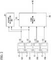
- FIG. 1is a conceptual drawing of a multocular imaging apparatus according to the first embodiment of the present invention.
- FIG. 2is a block diagram of the multocular imaging apparatus according to the same embodiment.
- the multocular imaging apparatus 10 of the present embodimenthas four sets of image pickup units 101, 102, 103, and 104. Each of the image pickup units 101, 102, 103, and 104 has an imaging lens 11 and an imaging element 12.
- the imaging lenses 11form the light from the captured object onto the imaging elements 12, and the formed image is photoelectric converted by the imaging elements 12, for example, a CMOS imaging element or the like, and is output as video signals V1, V2, V3, and V4.
- the video signals V1, V2, V3, and V4 output from the corresponding set of image pickup units 101, 102, 103, and 104are input to the video processing unit 20.
- the video signals V1 and V2, output from the two image pickup units 101 and 102are simultaneously input to the distance calculating unit 21 as well.
- the distance calculating unit 21performs corresponding point searching from the two input video signals V1 and V2 and, from the result of the search, calculates and outputs to the video processing unit 20 the parallax data D1 between the two image pickup units.
- the video processing unit 20performs synthesis processing of the input video signals V1, V2, V3, and V4 based on the parallax data D1 output from the distance calculating unit 21, and outputs a high-definition video V5.
- FIG. 3is a block diagram that shows the constitution of the distance calculating unit 21, which calculates the parallax data D1 from the image V1 (hereinafter referred to as the template image) captured by the image pickup unit 101 shown in FIG. 2 and the image V2 (hereinafter referred to as the reference image) captured by the image pickup unit 102.
- Two coordinate transforming units 31 and 32perform a geometrical transformation (coordinate transformation) of both images so as to make the epipolar lines thereof parallel, for the purpose of placing the image planes of the template image and the reference image on one and the same image plane.
- Camera parameters 30are internal parameters such as the focal length and lens distortion parameters that are peculiar to the image pickup unit 101, and external parameters that represent the positional relationship between the four image pickup units 101, 102, 103, and 104, these being held beforehand. Details of the camera parameters will be described later.
- a coordinate transforming unit 32holds camera parameters peculiar to the image pickup unit 102 (not shown).
- a corresponding point searching unit 33searches for corresponding points in the template image and the reference image, the epipolar lines of which have been made parallel, and determines and outputs the parallax data D1 of the reference image with respect to the template image.
- FIG. 4 and FIG. 5show the image planes after the epipolar lines of the reference image P1 and the template image P2 are made parallel.
- the determination of the pixel (corresponding point) in the reference image P1 that corresponds to a pixel in the template image P2will be described for the method of moving the pixel of interest on the template image P2, using the drawing of the template image P2 shown in FIG. 5 .
- a block that has the pixel of interest of the template image P2 at its center(hereinafter referred to as the block of interest) is moved from the upper-left of the image (searching start block B1) sequentially on a line toward the right side one pixel at a time and, in the case in which the moved block of interest reaches the right end of the line, the block of interest is moved sequentially on one line therebelow from the left side of the line toward the right side. This is repeated until the lower-right block (searching end block B2) of the template image is reached.
- the processing operation of searching for a block in the reference image P1 that is similar to one block of interest (template block of interest B3) in the template image P2 shown in FIG. 5will be described, using the drawing of the reference image P1 shown in FIG. 4 .
- the reference block of interestis sequentially moved toward the right side of the line one pixel at a time, this being repeated up until the searching end block B5 in the reference image shown in FIG. 4 .
- search range R1is a value that is determined by the maximum parallax of the captured photographed object and, depending upon the set search range, the shortest distance to the object for which the parallax data D1 can be calculated.
- search range R1is a value that is determined by the maximum parallax of the captured photographed object and, depending upon the set search range, the shortest distance to the object for which the parallax data D1 can be calculated.
- the above-noted search for the reference image block of interest B4is performed for each template block of interest B3 in the template image P2 shown in FIG. 5 .
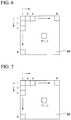
- FIG. 7shows the template block of interest B3, showing a block having a size of M horizontal pixels ⁇ N vertical pixels (where M and N are prescribed natural numbers), with the pixel of interest in the template image P2 at the center thereof.
- FIG. 6shows the reference block of interest B4, showing a block having a size of M horizontal pixels ⁇ N vertical pixels, with the pixel of interest in the reference image P1 at the center thereof.
- the pixel values at the coordinates (i, j)are R(i, j) and T(i, j).
- the method used for determining the degree of similarityis the commonly used SAD (sum of absolute difference) method.
- SADsum of absolute difference
- the value determinedis, as shown in the degree of similarity determining equation of Equation (1), the sum (SSAD) of the absolute values of the differences between R(i, j) and T(i, j) determined for all the pixels in the block.
- the template block of interest B3is set as the start (searching start block B1) of the template image P2 ( FIG. 5 ) (step S900). Then, all the pixel values of the template block of interest B3 are read out (step S901) from the template image P2 ( FIG. 5 ).
- the reference block of interest B4is set (step S902) as the start of (upper-left of the reference image P1) of the reference image P1 ( FIG. 4 ).
- step S903all the pixel values of the reference block of interest B4 are read out (step S903) from the reference image P1 ( FIG. 4 ).
- the SSAD value of the pixel values of the read out template block of interest B3 and the reference block of interest B4is calculated in accordance with Equation (1) and stored (step S904).
- step S905a determination is made as to whether or not the search range R1 has been completed (step S905) and, if it is not yet completed, the reference block of interest B4 is moved in the line direction toward the right side by one pixel (step S906) and the processing of step S903 and step S904 is performed again.
- the processing of these steps S903 to S906is repeated within the search range R1 and, after the completion of the calculation of all the SSAD values within the search range R1, the reference block of interest B3 having the smallest SSAD value is detected.
- the difference between the center coordinate of the template block of interest B3 (pixel of interest in the template image P2) and the center coordinate of the detected reference block of interest B4 (center coordinates in the reference image P1)becomes the parallax data D1 of the pixel of interest in the template image P2, which is stored (step S907).
- step S908a determination is made as to whether processing has been completed (step S908) and, if it is not completed, the template block of interest B3 is moved in the line direction toward the right side by one pixel (step S909), and the processing of step S901 to step S907 is performed again.
- the processing of these steps S901 to S909is repeated until the template block of interest B3 becomes the searching end block B2 of the template image P2 ( FIG. 5 ), and the parallax data D1 for each pixel in the template image P2 is determined.
- the reference block of interest B4 having the minimum SSAD valueis not necessarily the correct similar block.
- Erroneous detectionmay occur in cases in which there is no pattern (texture) in the template block of interest B3 or cases in which the searched region in the reference image P1 is an occlusion region.
- there is a parallax calculation error detection method and an occlusion detection methodand one example of these methods is described in Patent Document 3. Because various methods for reducing the erroneous detection of a similar block are known, they will not be described in detail herein.
- the parallax value of zero or a prescribed unique valueis stored as the parallax data D1.
- the methodis not restricted to this method, and any method of searching for similar pixels in the template image and the reference images may be used to determine the parallax data.
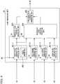
- the video processing unit 20has four compensation processing units 401-1 to 401-4, a monocular video synthesis processing unit 403, a multocular video synthesis processing unit 404, and a high-resolution synthesis processing unit 405.
- Each of the positioning compensation processing units 401-1 to 401-4has a storage apparatus into which the camera parameters 402 are stored, although these are illustrated within a single positioning compensation processing unit 401-1.
- the video signal V1 (template image) of the image pickup unit 101is applied to the positioning compensation processing unit 401-1 and, similarly, the video signals V2, V3, and V4 of the image pickup units 102, 103, and 104 are applied to the respective positioning compensation processing units 401-2, 401-3, and 401-4.
- the output of the positioning compensation processing unit 401-1is applied to the monocular video synthesis processing unit 403.
- the outputs of the positioning compensation processing units 401-1 to 401-4are applied to the multocular video synthesis processing unit 404.
- the output of the monocular video synthesis processing unit 403 and the output of the multocular video synthesis processing unit 404are synthesized to the high-definition video V5 in the high-resolution synthesis processing unit 405 and output to outside the video processing unit 20.
- the positioning compensation processing units 401-1 to 401-4based on the parallax data D1 output from the distance calculating unit 21 ( FIG. 3 ) and the camera parameters 402 that indicate the pointing and attitude of each of the image pickup units and the condition of lens distortion, perform position compensation so that the video of each of the image pickup units 101, 102, 103, and 104 captures the same position on the object to be captured.
- the monocular video synthesis processing unit 403synthesizes a region, for example, in which at an occlusion the parallax data D1 could not be calculated at the distance calculating unit 21, that is, a region for which the parallax value is zero or a prescribed unique value, at the distance calculating unit 21 for the video signal captured by the image pickup unit 101, which is taken as the reference.
- the multocular video synthesis processing unit 404performs high-definition synthesis of regions for which the parallax data D1 could be calculated at the distance calculating unit 21, using the video signals V1, V2, V3, and V4 of the four image pickup units 101, 102, 103, and 104.
- the camera parameters 402 that indicate the pointing and attitude of each of the image pickup units 101 to 104 and the condition of lens distortioncan be determined by calibration in which calculations are made from a number of captured images of a checkerboard pattern in which the pattern shape is known, while changing the attitude and angle to capture it several times.
- the camera parameters 402are constituted by external parameters and internal parameters.
- the external parametersare constituted by the three axis vectors of yaw, pitch, and roll that indicate the attitude of camera, and three parallel translation vectors that indicate parallel movement components, for a total of six parameters.
- the internal parametersare constituted by five parameters that represent the image center position, the angle and aspect ratio of the coordinate that were assumed on the imaging element, and the focal length.
- the shift amount calculated from the parallax data D1 up to the captured object and the spacing (camera base line length) between the reference image pickup unit 101 and the other image pickup units 102, 103, and 104is subjected to geometric compensation processing, using parameters that take into consideration the amount of parallel translation, which are external parameters of the camera parameters. By doing this, the video of the four image pickup units 101, 102, 103, and 104 are position adjusted so as to capture the same point on the captured object at the same position (pixel).
- the operation of the multocular video synthesis processing unit 404will be described.
- the horizontal axisindicates spatial broadening (size) and the vertical axis indicates the amplitude (brightness) of light.
- the reference symbol 40aindicates the light intensity distribution of the actual image.
- the reference symbols 40b and 40c in FIG. 10are pixels of the respective image pickup units 101 and 102, the relative positioning relationship of which is offset by the amount indicated by the arrow represented by the reference symbol 40d.
- the image elementsintegrate the light intensity in pixel units, when the contour of the object indicated by the reference symbol 40a is captured by the image pickup unit 101, the video signal of the light intensity distribution indicated by the reference symbol 40e is obtained, and when it is captured by the image pickup unit 102, the video signal of the light intensity distribution indicated by the reference symbol 40f is obtained.
- the video signal of the light intensity distribution indicated by the reference symbol 40gis obtained.
- FIG. 11shows an example of high-resolution synthesizing using the images obtained from each of the four image pickup units 101, 102, 103, and 104.
- the resolution of the four image pickup units 101, 102, 103, and 104is VGA (640 ⁇ 480 pixels) and high-resolution synthesis processing is done to a Quad-VGA (1280 ⁇ 960 pixels), which has four times of the number of pixels, will be described.
- FIG. 11by synthesizing the four pixels that are adjacent to the Quad-VGA pixels (1280 ⁇ 960 pixels) by assigning pixels captured by different image pickup units, it is possible to obtain a high-resolution image.
- the pixels on the uppermost line of the image P11 that is captured by the image pickup unit 101are, in sequence, G11, G12, G13, and so on, from the left.
- the pixels of the second linebe in the sequence G14, G15, G16, and so on, from the left.
- the pixels on the third linebe in the sequence G17, G18, G19, and so on, from the left.
- the pixels on the uppermost line of the image P12 that is captured by the image pickup unit 102are, in sequence, G21, G22, G23, and so on, from the left.
- the pixels of the second linebe in the sequence G24, G25, G26, and so on, from the left.
- the pixels on the third linebe in the sequence G27, G28, G29, and so on, from the left.
- the first line of the image P15 after high-resolution synthesis processinghas the interleaving of the pixels of the first lines of the images P1 1 and P12 captured by the image pickup units 101 and 102, this being, from the left, G11, G21, G12, G22, G13, G23, and so on in that sequence.
- the pixels of the first lines of the images P13 and P14 captured by the image pickup units 103 and 104are interleaved, this being, from the left, G32, G42, G33, G43, and so on, in that sequence.
- the processingis repeated so that the image P15 after high-resolution synthesis has the same type of arrangement.
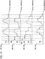
- FIG. 12 and FIG. 13an occlusion region and the operation of the monocular video synthesis processing unit 403, which performs video processing thereof, will be described.
- This descriptionwill be of the case in which a foreground region 61 (cube) disposed in front of a background region 62 is captured by each of the image pickup units 101 and 102.
- the top part of FIG. 13shows, in simplified form, a high-definition image 65 after high-resolution synthesis processing.
- an occlusion region 63occurs that is seen by the image pickup unit 101 but is hidden from the image pickup unit 102 so as not to be seen.
- the occlusion region 63is shown by hatching inclined downward toward the right.
- the reference symbol 65 shown in FIG. 13indicates the high-definition image generated by the video processing unit 20.
- the three graphs shown by the reference symbols 67, 68, and 69indicate the change in intensity along the straight line 66 in the high-definition image 65.
- the vertical axisindicates the luminance
- the horizontal axisindicates position. From the left side along the horizontal axis, there are the foreground region 61, the occlusion region 63, and the background region 62. Because the parallax data 64 can be calculated for the background region 62 and the foreground region 61, the high-resolution synthesis processing described by FIG. 10 and FIG. 11 is performed using the four image pickup units 101, 102, 103, and 104.
- the luminance curve C0 shown by a broken line in the graph 67which uses the video of the image pickup unit 101 as is, is applied.
- the luminance valueis reduced to correct it to the luminance curve shown by C1, as shown by the arrow A1 in graph 67 (luminance reduction compensation processing).
- the luminance in the occlusion region 63can be synthesized darker than the foreground region 61. For this reason, it is possible to effectively present an appearance in a manner that approaches the human visual psychological effect of a dark appearance because of the occlusion, with the perception of brightness with depth.
- step S800the pixel that is to be subjected to video processing is specified (step S800).
- step S801a determination is made (step S801) of whether or not the specified pixel is an occlusion region 63. If it is not an occlusion region 63, that is, in the case in which the parallax data 64 could be calculated, positioning compensation processing by the camera parameters and the parallax data 64 is performed in all the video of the four image pickup units 101, 102, 103, and 104 (step S802).
- multocular video synthesis processingis performed by the multocular video synthesis processing unit 404 (step S803).
- step S804compensation processing is performed for the video of the image pickup unit 101, the parallax data 64 being zero (step S804). Then, monocular video synthesis processing (luminance reduction compensation processing, joining compensation processing, or smoothing compensation processing) is executed (step S805). The above-noted processing is repeated until the imaging processing is completed (step S806).
- FIG. 15is a block diagram showing the constitution of a multocular imaging apparatus according to the second embodiment.
- FIG. 16is a block diagram showing the constitution of the distance calculating unit 151 shown in FIG. 15 .
- the point of difference in the multocular imaging apparatus shown in FIG. 15 with respect to the multocular imaging apparatus 10 shown in FIG. 2is that, rather than the distance calculating unit 21, it is provided with a distance calculating unit 151.
- the parallax data D11 that the distance calculating unit 151 outputsis sent to the video processing unit 20 shown in FIG. 15 .
- the video processing unit 20 shown in FIG. 15with the exception of changing the parallax data D1 of the video processing unit 20 shown in FIG. 9 to read D11, is the same as the video processing unit 20 shown in FIG. 9 , the description thereof is omitted.
- the distance calculating unit 151 shown in FIG. 15inputs the video signals V1, V2, V3, and V4 from the four image pickup units 101, 102, 103, and 104, respectively, and calculates the distance (parallax).
- the distance calculating unit 151inputs the video signals V1, V2, V3, and V4 captured from the four image pickup units 101, 102, 103, and 104, respectively.
- the distance calculating unit 151 shown in FIG. 16inputs the video signals V1, V2, V3, and V4 captured from the four image pickup units 101, 102, 103, and 104, respectively.
- the distance calculating unit 151 shown in FIG. 16inputs the video signals V1, V2, V3, and V4 captured from the four image pickup units 101, 102, 103, and 104, respectively.
- the coordinate transforming units 81 to 84perform a geometrical transformation (coordinate transformation) of each image for the purpose of placing the image planes of the template image P21 and each of the reference images P11 to P13 on the same plane. Because the coordinate transformation processing is the same as in the coordinate transforming units 31 and 32 shown in FIG. 3 , its detailed described is omitted herein.
- the corresponding point searching units 85 to 87searches for corresponding points between the transformed template image P21 and each of the reference images P11 to P13, and determines the parallax data D11 of each of the reference images P11 to P13 with respect to the template image P21.
- the corresponding point searching unit 85calculates the parallax data D12 between the template image P21 and the first reference image P11, in the same manner as in the corresponding point searching unit 33 shown in FIG. 3 .
- the corresponding point searching unit 85also outputs detection-not-possible information that indicates a parallax calculation error or an occlusion pixel of interest to the corresponding point searching unit 86.
- This detection-not-possible informationcan be, for example, setting the coordinate information of the coordinates of interest to -1, which indicates that detection is not possible.
- the coordinating point searching unit 86calculates the parallax data D13 between the geometrically transformed template image P21 and the second reference image P12. However, the corresponding point searching unit 85 searches for a corresponding point between the geometrically transformed template image P21 and the overall first reference image P11. In contrast, the corresponding point searching unit 86, in accordance with the detection-not-possible information sent from the corresponding point searching unit 85, with regard to pixels of interest in the template image P21 for which a parallax error or an occlusion is detected, searches for the corresponding pixel from the second reference image P12 and calculates the parallax data D13. When this is done, similar to the corresponding point searching unit 85, if a parallax calculation error or occlusion is detected, detection-not-possible information is sent to the corresponding point searching unit 87.
- the corresponding point searching unit 87similar to the corresponding point searching unit 86, in accordance with detection-not-possible information sent from the corresponding point searching unit 86, with regard to the geometrically transformed template image P21 and the third reference image P13, for a pixel of interest of the template image P21 for which a parallax calculation error or occlusion is detected, searches for a corresponding pixel from the third reference image P13, and calculates the parallax data D14.
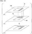
- FIG. 17shows the template image P21 and occlusion regions 63 each of the reference images P211, P12, and P13.
- the parallax data D12for which the occlusion region 63 occurs at the right side of the captured object 200.
- the drawing (lower-right of FIG. 17 )shows the parallax data D12 for which the occlusion region 63 occurs at the right side of the captured object 200.
- FIG. 18shows in hierarchal form the parallax data D12, D13, and D14 between each of the reference images P11, P12, and P13 shown in FIG. 17 .
- the second embodimentwith regard to region in which a parallax calculation error or occlusion region is detected with respect the parallax data D12 determined between the template image P21 and the first reference image P11, determination was done from a reference image other than these regions. Additionally, in the case in which a parallax calculation error or occlusion is detected, the parallax data D11 is hierarchally calculated by the method of calculation from a new reference image that is not used.
- distance informationis calculated from searching for corresponding points with regard to two video pairs from three or more cameras, and selection is made of either synthesizing processing of high-definition video from a plurality of camera video based on that distance information, or generating synthesized video from the camera video from one camera that is the reference. For this reason, compared with the conventional art of performing corresponding point searching between all the camera videos, it is possible to achieve a dramatic reduction in the amount of processing, and to suppress the deterioration of image quality in a region (occlusion regions or the like) in which distance information could not be calculated.
- distance informationis calculated for regions in which the distance information could not be calculated by using the video of a different camera, it is possible to reduce the regions in which the distance information cannot be calculated. Additionally, because the regions in which synthesis is possible of high-definition video from a plurality of camera video are increased, it is possible to generate video with better definition.
- distance informationis calculated for regions in which the distance information could not be calculated by using video of a different camera, compared with conventional art in which searching is done for corresponding points between all camera videos, it is possible to greatly reduce the amount of processing. Also, by reducing the luminance of regions such as occlusion regions in which it was not possible to calculate the distance information, thereby preventing achievement of high definition, by a prescribed ratio, synthesis is possible without having those regions stand out. Along with that, it is possible to effectively present an appearance that matches the human visual psychological effect of the brightness perception of darkness with the depth of the occlusion.
- the video luminance in a region such as an occlusion region in which distance information could not be calculated and high definition could not be achievedmay be generated as darker than the luminance of a region that is adjacent to and in front thereof.
- the video luminance in a regionmay be generated by adjusting the luminance to coincide with the luminance of a region that is adjacent to and further to the rear from that region.
- continuityis maintained between the occlusion region and a rear region with which it is to be continuous, thereby enabling synthesis of an appearance that does not present an unnatural visual psychological effect.
- a region such as an occlusion region in which distance information could not be calculated dcan be synthesized by reducing the color saturation thereof by a prescribed ratio, so that the region does not stand out.
- the color saturation in a region such as an occlusion region in which the distance information could not be calculatedmay be generated by reducing the saturation to lower than that of an adjacent region that is further in the foreground.
- a regionsuch as an occlusion region, in which the distance information could not be calculated, may be generated by adjusting the color saturation to coincide with that of an adjacent region that is further in the background. By doing this, continuity is maintained between the occlusion region and a background region to which it is to be made continuous, thereby enabling synthesis of an appearance that does not present an unnatural visual psychological effect.
- a region such as an occlusion region in which the distance information could not be calculatedmay be blurred.
- a program for the purpose of implementing the functions of the video processing unit 20 and the distance calculating unit 21 shown in FIG. 2 , and the distance calculating unit 151 shown in FIG. 15may be recorded on a computer-readable recording medium, and a computer system may read and execute the program recorded on the recording medium, thereby performing synthesis of the high-definition image.
- the term "computer system”includes an operating system and also hardware, such as peripheral devices.
- the term "computer-readable recording medium”refers to a portable medium, such as a flexible disk, an optical-magnetic disc, a ROM, and a CD-ROM, and a storage device, such as a hard disk that is built into a computer system.
- computer-readable recording mediumfurther includes something that retains a program for a certain time, such as a flash memory (RAM) internally provided in a computer system acting as the server and client in the case in which the program is transmitted via a network such as the Internet, and a communication line such as a telephone line.
- a flash memoryRAM
- the above-programmay be transferred from the computer system holding this program in a memory device and the like to the other computer system via a transmission medium or by a transmission wave in a transmission medium.
- transmission mediumthat transmits a program refers to a medium that has the function transferring information, for example, a network (communication network) of the Internet or the like and communication line (communication wire) such as a telephone line.
- the programmay have the object of implementing a part of the above-described functions, and it may also implement the above-described function in combination with a program already stored in a computer system, that is, it may be a differential file (differential program).
- the present inventionis applicable to an image pickup apparatus that obtains a high-definition image by synthesizing a plurality of images obtained by using a plurality of image pickup systems.
Landscapes
- Engineering & Computer Science (AREA)
- Multimedia (AREA)
- Signal Processing (AREA)
- Theoretical Computer Science (AREA)
- General Physics & Mathematics (AREA)
- Physics & Mathematics (AREA)
- Computer Vision & Pattern Recognition (AREA)
- Computing Systems (AREA)
- Human Computer Interaction (AREA)
- Studio Devices (AREA)
- Image Processing (AREA)
- Studio Circuits (AREA)
- Testing, Inspecting, Measuring Of Stereoscopic Televisions And Televisions (AREA)
- Measurement Of Optical Distance (AREA)
Description
- The present invention relates to a multocular image pickup apparatus and a multocular image pickup method.
- In recent years, digital still cameras and digital video cameras (hereinafter referred to as digital cameras) with high image quality have seen rapid growth in use. Digital cameras are also, in parallel with this, advancing in compactness and light weight, and compact digital cameras with high image quality have come to be incorporated into cellular telephone handsets and the like. Image pickup apparatuses, a typical form of which is a digital camera, include a lens optical system, which forms an image, and imaging elements, which photoelectric convert light formed as an image so as to output electrical signals. The imaging elements used are electronic devices such as CMOS (complementary metal oxide semiconductor) sensors or CCD (charge-coupled device) sensors or the like. These imaging elements photoelectric convert the distribution of light amount of the image that is formed on the image plane, so as to record it as the image plane image. In order to remove aberrations, lens optical systems are often made up of several aspherical lenses. In the case of incorporating a zoom function, a drive mechanism (actuator) is required to change the distance between a plurality of lens and the imaging elements.
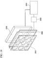
- In response to the demand for image pickup apparatuses with higher image quality and more sophisticated functionality, imaging elements have increased in numbers of pixels and higher definition, and image-forming optical systems are advancing in providing lower aberration and improved definition. This has been accompanied by the image pickup apparatus increasing in size, leading to the problem of difficulty in achieving compactness and thinness. With respect to such problem, proposals have been made to adopt a compound-eye structure in the lens optical system, and to use an image pickup apparatus constituted by a plurality of imaging elements and lens optical systems. For example, an imaging lens apparatus has been proposed having a constitution that includes a solid lens array disposed in a planar manner, a liquid-crystal array, and an imaging element (for example, refer to Patent Document 1). This imaging lens apparatus, as shown in
FIG. 19 , has a lens system that has alens array 2001 and a variable focal length liquid-crystal lens array 2002 with the same number of lenses, animaging element 2003, anarithmetic unit 2004, and a liquid-crystal drive unit 2005. - The
imaging element 2003 images the optical image formed via this lens system. - The
arithmetic unit 2004 image processes the plurality of images obtained from theimaging element 2003 so as to reconstitute the overall image. - The liquid-
crystal drive unit 2005 detects focus information from thearithmetic unit 2004, so as to drive the liquid-crystal lens array 2002. - By adopting this constitution, a compact thin imaging lens apparatus with a shortened focal length can be implemented.
- A thin-type color camera that has a sub-pixel resolution by combining four sub-cameras constituted by an imaging lens, a color filter, and a detector array has also been proposed (for example, refer to Patent Document 2). This thin-
type color camera 200, as shown inFIG. 20A and FIG. 20B , is constituted by alens 220, acolor filter 250, and adetector array 240. Thelens 220 has fourlenses 220a to 220d. Thecolor filter 250 has fourcolor filters 250a to 250d. Thecolor filter 250, as shown inFIG. 20B is constituted by thefilter 250a, which passes red light (R), thefilters filter 250d, which passes blue light (B). Thedetector array 240 images an image of red light, green light, and blue light. With this constitution, it is possible to obtain a full-color image by combining, with red and blue, a synthesized high-resolution image formed from two images of green light, with respect to which the human visual system has a high sensitivity. - In the case of synthesizing a high-resolution image from a plurality of images photographed with this plurality of cameras, it is necessary to synthesize by searching for corresponding points taken from the same region in each of the images. However, because of the occurrence of regions that can be photographed from one of the cameras but that cannot be photographed in what is called an occlusion, being hidden from the other camera behind an object, there are cases in which corresponding points cannot be obtained. There is the problem that, this occlusion region, because of erroneous searching for corresponding points, leads to a deterioration in image quality in the high-definition synthesized image. A known apparatus to solve this type of problem is a multocular imaging apparatus in which, in processing to synthesize a high-definition image from a template image and a reference image, in a region in which it is not possible to obtain pairs of corresponding points, the corresponding point of the template image is used as the synthesized image generated data, and the corresponding point in the reference image is not used as the synthesized image generated data (refer to, for example, Patent Document 3). This multocular imaging apparatus, in synthesizing a high-definition image from two images, of a left imaging system and a right imaging system, has an occlusion region determining unit that determines whether or not an occlusion region exists in which corresponding points cannot be obtained.
Patent Document 3 discloses processing in which one of the images is not used as the synthesized image data in the occlusion region. By this constitution, it is said, it is possible to omit the processing procedure in a region in which an occlusion occurs, and also possible to suppress the deterioration of the image quality caused by error handling. US 5 682 198 A discloses a double eye image pickup apparatus that performs image pickup using a plurality of image pickup systems with partly overlapping fields in order to obtain an image at an arbitrary aspect ratio while correcting the registration and taking an image of occlusion area into consideration, and the apparatus has a device for setting a virtual projection plane in a subject space, based on image signals of overlap portions output from the respective image pickup systems, and a device for projecting image signals onto the projection plane to combine the image signals into a single image signal.WO 2009/151903 A2 discloses a camera array, an imaging device and/or a method for capturing image that employ a plurality of imagers fabricated on a substrate. Each imager includes a plurality of pixels. The plurality of imagers include a first imager having a first imaging characteristics and a second imager having a second imaging characteristics. The images generated by the plurality of imagers are processed to obtain an enhanced image compared to images captured by the imagers. Each imager may be associated with an optical element fabricated using a wafer level optics (WLO) technology.WO 2008/102898 A1 discloses an image quality improvement processing device for eliminating a shielding region or a big position alignment error region, selecting a pixel suitable for image quality improvement, and generating a high quality image. The image quality improvement processing device is comprised of a means that carries out position alignment processing for a standard image and an input image, and generates a position alignment processed standard image; a means that selects a pixel to be used for image quality improvement under a predetermined condition in accordance with the position alignment processed standard image and the input image, synthesizes images in accordance with the selected image and the input image, and generates a pixel selected input image; a means that corrects a pixel value of the pixel selected input image to make a pixel luminance of the pixel selected input image equal to a pixel luminance of the position alignment processed standard image, and generates a pixel selected and luminance corrected input image; and a means that carries out image quality improvement in accordance with the pixel selected and luminance corrected input image to generate a high quality image.- Patent Document 1: Japanese Unexamined Patent Application Publication No.
2006-251613 - Patent Document 2: Published Japanese Translation of
PCT Application No. JP-T-2007-520166 - Patent Document 3: Japanese Unexamined Patent Application Publication No.
H6-141237 - Although the multocular imaging apparatus of
Patent Document 3 uses a multocular imaging apparatus having two cameras, left and right, it says that the number of cameras is not limited to two, and can be three or more. However, in the case of providing three or more cameras, because searching is performed for corresponding points between all camera pairs, there is a problem that the amount of processing increases commensurately with the multiple of the number of camera pairs. InPatent Document 3, template matching is described as a known method of searching for corresponding points, in which the similarity between blocks surrounding in their center one point in the template image with a block in the reference image is compared, the center pixel of the block having the highest similarity being taken as the corresponding point. - In this detection method, however, as the camera resolution increases, not only does the amount of processing become extremely large, but also synthesis of a high-definition image requires the detection of corresponding points with a precision that exceeds the camera resolution, that is, with sub-pixel precision. For this reason, the amount of the processing for detection of corresponding points becomes significantly greater than that for high-definition synthesis processing. With the constitution of
Patent Document 3, if the number of cameras is increased for high definition, there is a commensurate increase in the amount of processing for corresponding point detection. In the case of imaging a movie, for example, it is necessary to detect corresponding points during the time period of one pixel clock, this leading to the problem of it being difficult during this time period to detect the corresponding points with high precision between all the cameras. One pixel clock, specifically, is 0.007 µs for the case of 1080/60P Hi-Vision movies. - The present invention was made in consideration of the above-noted situation, and has as an object to provide a multocular imaging apparatus and multocular imaging method capable of, in high-definition synthesis processing using three or more cameras, suppressing the deterioration of image quality in an occlusion region or in a corresponding point detection error region in which corresponding points cannot be found, without a great increase in the amount of processing.
- A further object is to provide a multocular imaging apparatus and multocular imaging method capable of rendering a region, in which high definition was not possible because of failure to detect corresponding points in a manner approaching the visual psychological effect as when seen by the left and right human eyes, thereby improving the appearance of the overall high-definition synthesized image.
- The above objects are solved by the subject-matter of the independent claims.
- (1) A first aspect of the present invention is a multocular image pickup apparatus according to
claim 1. - (2) In the first aspect of the present invention, the monocular video synthesizing unit may reduce, by a prescribed ratio, the luminance of the regions where the distance information could not be calculated in the distance calculation unit so as to generate the synthesized image.
- (3) In the first aspect of the present invention, the monocular video synthesizing unit may lower a luminance value of the regions, where the distance information could not be calculated in the distance calculation unit, to lower than that of foreground regions adjacent thereto, so as to generate the synthesized image.
- (4) In the first aspect of the present invention, the monocular video synthesizing unit may cause the luminance value of the regions where the distance information could not be calculated in the distance calculation unit are made to coincide with that of a background region adjacent thereto, so as to generate the synthesized image.
- (5) In the first aspect of the present invention, the monocular video synthesizing unit may reduce, by the prescribed ratio, the color saturation of the regions where the distance information could not be calculated in the distance calculation unit, so as to generate the synthesized image.
- (6) In the first aspect of the present invention, the monocular video synthesizing unit may lower color saturation of the regions where the distance information could not be calculated in the distance calculation unit to lower than that of foreground regions adjacent thereto, so as to generate the synthesized image.
- (7) In the first aspect of the present invention, the monocular video synthesizing unit may cause the color saturation of the regions where the distance information could not be calculated in the distance calculation unit to conform with that of the background region adjacent thereto, so as to generate the synthesized image.
- (8) In the first aspect of the present invention, the monocular video synthesizing unit may suppress a change of luminance of the regions where the distance information could not be calculated in the distance calculation unit so as to generate the synthesized image.
- (9) A second aspect of the present invention is a multocular image pickup method according to
claim 10. - According to the present invention, in high-definition synthesis processing using two or more cameras, it is possible to achieve suppression of the deterioration of image quality in an occlusion region or a corresponding point detection error region in which corresponding points cannot be found, without increasing the amount of processing. Additionally, it is possible to achieve the effect of rendering a region in which high definition was not possible because of failure to detect corresponding points in a manner that approaches the visual psychological effect as when seen by the left and right human eyes, thereby improving the appearance of the overall high-definition synthesized image.
FIG. 1 is a conceptual drawing of a multocular imaging apparatus according to the first embodiment of the present invention.FIG. 2 is an overall block diagram of the multocular imaging apparatus according to the first embodiment.FIG. 3 is a block diagram of a distance calculating unit of the multocular imaging apparatus according to the first embodiment.FIG. 4 is a schematic representation showing the corresponding point searching processing of the multocular imaging apparatus according to the first embodiment.FIG. 5 is a schematic representation showing the corresponding point searching processing of the multocular imaging apparatus according to the first embodiment.FIG. 6 is a schematic representation showing the corresponding point searching processing of the multocular imaging apparatus according to the first embodiment.FIG. 7 is a schematic representation showing the corresponding point searching processing of the multocular imaging apparatus according to the first embodiment.FIG. 8 is a flowchart of the corresponding point searching processing of the multocular imaging apparatus according to the first embodiment.FIG. 9 is a block diagram of the video processing unit of the multocular imaging apparatus according to the first embodiment.FIG. 10 is a schematic representation describing the operation of the multocular video synthesis processing unit of the multocular imaging apparatus according to the first embodiment.FIG. 11 is a schematic representation describing the operation of a quadrocular synthesis processing unit of the multocular imaging apparatus according to the first embodiment.FIG. 12 is a schematic representation describing an occlusion region and describing the operation of a monocular video synthesis processing unit in the multocular imaging apparatus according to the first embodiment.FIG. 13 is a schematic representation describing an occlusion region and describing the operation of a monocular video synthesis processing unit in the multocular imaging apparatus according to the first embodiment and.FIG. 14 is a flowchart describing the operation of the video processing unit of the multocular imaging apparatus according to the first embodiment.FIG. 15 is an overall block diagram of a multocular imaging apparatus according to a second embodiment.FIG. 16 is a block diagram of the distance calculating unit of the multocular imaging apparatus according to the second embodiment.FIG. 17 is a schematic representation showing the corresponding point searching method of the multocular imaging apparatus according to the second embodiment.FIG. 18 is a schematic representation showing the corresponding point searching method of the multocular imaging apparatus according to the second embodiment.FIG. 19 is a block diagram showing the constitution of a conventional multocular imaging apparatus.FIG. 20A is a block diagram showing the constitution of another conventional multocular imaging apparatus.FIG. 20B is a simplified drawing of the constitution of the color filter of the multocular imaging apparatus ofFIG. 20A .- The multocular imaging apparatus according to the first embodiment of the present invention will be described below, with references made to the drawings.
FIG. 1 is a conceptual drawing of a multocular imaging apparatus according to the first embodiment of the present invention.FIG. 2 is a block diagram of the multocular imaging apparatus according to the same embodiment. As shown inFIG. 1 , themultocular imaging apparatus 10 of the present embodiment has four sets ofimage pickup units image pickup units imaging lens 11 and animaging element 12. Theimaging lenses 11 form the light from the captured object onto theimaging elements 12, and the formed image is photoelectric converted by theimaging elements 12, for example, a CMOS imaging element or the like, and is output as video signals V1, V2, V3, and V4. By capturing by each of the four sets ofimage pickup units image pickup units video processing unit 20. Of the four sets of video signals, the video signals V1 and V2, output from the twoimage pickup units distance calculating unit 21 as well. Thedistance calculating unit 21 performs corresponding point searching from the two input video signals V1 and V2 and, from the result of the search, calculates and outputs to thevideo processing unit 20 the parallax data D1 between the two image pickup units. Thevideo processing unit 20 performs synthesis processing of the input video signals V1, V2, V3, and V4 based on the parallax data D1 output from thedistance calculating unit 21, and outputs a high-definition video V5. - Next, referring to
FIG. 3 , the constitution of thedistance calculating unit 21 shown inFIG. 2 will be described.FIG. 3 is a block diagram that shows the constitution of thedistance calculating unit 21, which calculates the parallax data D1 from the image V1 (hereinafter referred to as the template image) captured by theimage pickup unit 101 shown inFIG. 2 and the image V2 (hereinafter referred to as the reference image) captured by theimage pickup unit 102. Two coordinate transformingunits Camera parameters 30 are internal parameters such as the focal length and lens distortion parameters that are peculiar to theimage pickup unit 101, and external parameters that represent the positional relationship between the fourimage pickup units unit 32 holds camera parameters peculiar to the image pickup unit 102 (not shown). A correspondingpoint searching unit 33 searches for corresponding points in the template image and the reference image, the epipolar lines of which have been made parallel, and determines and outputs the parallax data D1 of the reference image with respect to the template image. - Next, referring to
FIG. 4 to FIG. 7 , the processing operation for searching for corresponding pixels will be described.FIG. 4 and FIG. 5 show the image planes after the epipolar lines of the reference image P1 and the template image P2 are made parallel. The determination of the pixel (corresponding point) in the reference image P1 that corresponds to a pixel in the template image P2 will be described for the method of moving the pixel of interest on the template image P2, using the drawing of the template image P2 shown inFIG. 5 . A block that has the pixel of interest of the template image P2 at its center (hereinafter referred to as the block of interest) is moved from the upper-left of the image (searching start block B1) sequentially on a line toward the right side one pixel at a time and, in the case in which the moved block of interest reaches the right end of the line, the block of interest is moved sequentially on one line therebelow from the left side of the line toward the right side. This is repeated until the lower-right block (searching end block B2) of the template image is reached. - Next, the processing operation of searching for a block in the reference image P1 that is similar to one block of interest (template block of interest B3) in the template image P2 shown in
FIG. 5 will be described, using the drawing of the reference image P1 shown inFIG. 4 . From a block (reference block of interest B4) in the reference image P1 having the same coordinates as the coordinates (x, y) of the template block of interest B3 in the template image P2 shown inFIG. 5 , the reference block of interest is sequentially moved toward the right side of the line one pixel at a time, this being repeated up until the searching end block B5 in the reference image shown inFIG. 4 . The search range in this case (search range R1) is a value that is determined by the maximum parallax of the captured photographed object and, depending upon the set search range, the shortest distance to the object for which the parallax data D1 can be calculated. The above-noted search for the reference image block of interest B4 is performed for each template block of interest B3 in the template image P2 shown inFIG. 5 . - Next, the method of determining the reference image block of interest B4 similar to the template block of interest B3 will be described, with references made to
FIG. 6 and FIG. 7. FIG. 7 shows the template block of interest B3, showing a block having a size of M horizontal pixels × N vertical pixels (where M and N are prescribed natural numbers), with the pixel of interest in the template image P2 at the center thereof.FIG. 6 shows the reference block of interest B4, showing a block having a size of M horizontal pixels × N vertical pixels, with the pixel of interest in the reference image P1 at the center thereof. To represent arbitrary pixels in the reference block of interest B4 shown inFIG. 6 and the template block of interest B3 shown inFIG. 7 , with the horizontal direction taken as i and the vertical direction taken as j, the pixel values at the coordinates (i, j) are R(i, j) and T(i, j). The method used for determining the degree of similarity is the commonly used SAD (sum of absolute difference) method. In the SAD method, the value determined is, as shown in the degree of similarity determining equation of Equation (1), the sum (SSAD) of the absolute values of the differences between R(i, j) and T(i, j) determined for all the pixels in the block. The determination of a reference block of interest B4 that is similar to the template block of interest B3 is made by taking, of each reference block of interest B4 within the search range R1 in the reference image P1 shown in the above-notedFIG. 4 , the reference block of interest B4 having the smallest value of SSAD as being similar to the template block of interest B3.
[Equation 1]
- Although the foregoing description is for the case of performing the method of calculating the parallax data D1 for each processing unit, the method of processing in accordance with the sequence of the input pixels will be described with references made to processing flowing shown in
FIG. 4 to FIG. 7 andFIG. 8 . First, the template block of interest B3 is set as the start (searching start block B1) of the template image P2 (FIG. 5 ) (step S900). Then, all the pixel values of the template block of interest B3 are read out (step S901) from the template image P2 (FIG. 5 ). Next, the reference block of interest B4 is set (step S902) as the start of (upper-left of the reference image P1) of the reference image P1 (FIG. 4 ). Then, all the pixel values of the reference block of interest B4 are read out (step S903) from the reference image P1 (FIG. 4 ). The SSAD value of the pixel values of the read out template block of interest B3 and the reference block of interest B4 is calculated in accordance with Equation (1) and stored (step S904). - Next, a determination is made as to whether or not the search range R1 has been completed (step S905) and, if it is not yet completed, the reference block of interest B4 is moved in the line direction toward the right side by one pixel (step S906) and the processing of step S903 and step S904 is performed again. The processing of these steps S903 to S906 is repeated within the search range R1 and, after the completion of the calculation of all the SSAD values within the search range R1, the reference block of interest B3 having the smallest SSAD value is detected. The difference between the center coordinate of the template block of interest B3 (pixel of interest in the template image P2) and the center coordinate of the detected reference block of interest B4 (center coordinates in the reference image P1) becomes the parallax data D1 of the pixel of interest in the template image P2, which is stored (step S907).
- Then, a determination is made as to whether processing has been completed (step S908) and, if it is not completed, the template block of interest B3 is moved in the line direction toward the right side by one pixel (step S909), and the processing of step S901 to step S907 is performed again. The processing of these steps S901 to S909 is repeated until the template block of interest B3 becomes the searching end block B2 of the template image P2 (
FIG. 5 ), and the parallax data D1 for each pixel in the template image P2 is determined. - When, in step S907, the reference block of interest B4 having the minimum SSAD value is detected, the reference block of interest B4 having the minimum value is not necessarily the correct similar block. Erroneous detection may occur in cases in which there is no pattern (texture) in the template block of interest B3 or cases in which the searched region in the reference image P1 is an occlusion region. In order to reduce such erroneous detection of a similar block, there is a parallax calculation error detection method and an occlusion detection method, and one example of these methods is described in
Patent Document 3. Because various methods for reducing the erroneous detection of a similar block are known, they will not be described in detail herein. With regard to a pixel of interest in the template image in the case in which a detection is made of a parallax calculation error or an occlusion in the searches at step S907, the parallax value of zero or a prescribed unique value is stored as the parallax data D1. - Although the above description is for a pixel in the reference image that is similar to a pixel of interest in the template image using the similarity evaluation function of SAD as an example of a processing method in the corresponding
point searching unit 33 shown inFIG. 3 , the method is not restricted to this method, and any method of searching for similar pixels in the template image and the reference images may be used to determine the parallax data. - Next, the constitution and the operation of the
video processing unit 20 shown inFIG. 2 will be described, with reference made toFIG. 9 . Thevideo processing unit 20 has four compensation processing units 401-1 to 401-4, a monocular videosynthesis processing unit 403, a multocular videosynthesis processing unit 404, and a high-resolutionsynthesis processing unit 405. Each of the positioning compensation processing units 401-1 to 401-4 has a storage apparatus into which thecamera parameters 402 are stored, although these are illustrated within a single positioning compensation processing unit 401-1. The video signal V1 (template image) of theimage pickup unit 101 is applied to the positioning compensation processing unit 401-1 and, similarly, the video signals V2, V3, and V4 of theimage pickup units synthesis processing unit 403. The outputs of the positioning compensation processing units 401-1 to 401-4 are applied to the multocular videosynthesis processing unit 404. The output of the monocular videosynthesis processing unit 403 and the output of the multocular videosynthesis processing unit 404 are synthesized to the high-definition video V5 in the high-resolutionsynthesis processing unit 405 and output to outside thevideo processing unit 20. - The positioning compensation processing units 401-1 to 401-4, based on the parallax data D1 output from the distance calculating unit 21 (
FIG. 3 ) and thecamera parameters 402 that indicate the pointing and attitude of each of the image pickup units and the condition of lens distortion, perform position compensation so that the video of each of theimage pickup units synthesis processing unit 403 synthesizes a region, for example, in which at an occlusion the parallax data D1 could not be calculated at thedistance calculating unit 21, that is, a region for which the parallax value is zero or a prescribed unique value, at thedistance calculating unit 21 for the video signal captured by theimage pickup unit 101, which is taken as the reference. The multocular videosynthesis processing unit 404 performs high-definition synthesis of regions for which the parallax data D1 could be calculated at thedistance calculating unit 21, using the video signals V1, V2, V3, and V4 of the fourimage pickup units - Next, the operation of the positioning compensation processing units 401-1 to 401-4 will be described. The
camera parameters 402 that indicate the pointing and attitude of each of theimage pickup units 101 to 104 and the condition of lens distortion can be determined by calibration in which calculations are made from a number of captured images of a checkerboard pattern in which the pattern shape is known, while changing the attitude and angle to capture it several times. Thecamera parameters 402 are constituted by external parameters and internal parameters. The external parameters are constituted by the three axis vectors of yaw, pitch, and roll that indicate the attitude of camera, and three parallel translation vectors that indicate parallel movement components, for a total of six parameters. The internal parameters are constituted by five parameters that represent the image center position, the angle and aspect ratio of the coordinate that were assumed on the imaging element, and the focal length. At this point, the case of adjusting the video of the otherimage pickup units image pickup unit 101, using theimage pickup unit 101 as the reference, will be described. The shift amount calculated from the parallax data D1 up to the captured object and the spacing (camera base line length) between the referenceimage pickup unit 101 and the otherimage pickup units image pickup units - Next, referring to
FIG. 10 , the operation of the multocular videosynthesis processing unit 404 will be described. InFIG. 10 , the horizontal axis indicates spatial broadening (size) and the vertical axis indicates the amplitude (brightness) of light. To simplify the description, the synthesis processing for two images captured by the twoimage pickup units reference symbol 40a indicates the light intensity distribution of the actual image. Thereference symbols 40b and 40c inFIG. 10 are pixels of the respectiveimage pickup units reference symbol 40d. Because the image elements integrate the light intensity in pixel units, when the contour of the object indicated by thereference symbol 40a is captured by theimage pickup unit 101, the video signal of the light intensity distribution indicated by thereference symbol 40e is obtained, and when it is captured by theimage pickup unit 102, the video signal of the light intensity distribution indicated by thereference symbol 40f is obtained. By synthesizing these two images, it is possible to reconstitute a high-definition image indicated by thereference symbol 40g, which is close to the actual contour. - In
FIG. 10 , although the description was for the high-resolution synthesis processing using two images,FIG. 11 shows an example of high-resolution synthesizing using the images obtained from each of the fourimage pickup units image pickup units FIG. 11 , by synthesizing the four pixels that are adjacent to the Quad-VGA pixels (1280 × 960 pixels) by assigning pixels captured by different image pickup units, it is possible to obtain a high-resolution image. - As an example, let us say that the pixels on the uppermost line of the image P11 that is captured by the
image pickup unit 101 are, in sequence, G11, G12, G13, and so on, from the left. In the same manner, let the pixels of the second line be in the sequence G14, G15, G16, and so on, from the left. And let the pixels on the third line be in the sequence G17, G18, G19, and so on, from the left. - And let us say that the pixels on the uppermost line of the image P12 that is captured by the
image pickup unit 102 are, in sequence, G21, G22, G23, and so on, from the left. In the same manner, let the pixels of the second line be in the sequence G24, G25, G26, and so on, from the left. And let the pixels on the third line be in the sequence G27, G28, G29, and so on, from the left. - In the same manner, the reference symbols G31 to G39 and G41 to G49 as shown in
FIG. 11 to the pixels of the images P13 and P14 captured by theimage pickup units images P1 1 and P12 captured by theimage pickup units image pickup units FIG. 11 , the processing is repeated so that the image P15 after high-resolution synthesis has the same type of arrangement. - Next, referring to
FIG. 12 andFIG. 13 , an occlusion region and the operation of the monocular videosynthesis processing unit 403, which performs video processing thereof, will be described. This description will be of the case in which a foreground region 61 (cube) disposed in front of abackground region 62 is captured by each of theimage pickup units FIG. 13 shows, in simplified form, a high-definition image 65 after high-resolution synthesis processing. In the case of taking theimage pickup unit 101 as the reference, in theparallax data 64 calculated by thedistance calculating unit 21, anocclusion region 63 occurs that is seen by theimage pickup unit 101 but is hidden from theimage pickup unit 102 so as not to be seen. InFIG. 13 , theocclusion region 63 is shown by hatching inclined downward toward the right. - For the
occlusion region 63, in which parallax data cannot be calculated, because video processing is performed at the monocular videosynthesis processing unit 403 shown inFIG. 9 , using the video of theimage pickup unit 101 that is taken as the reference, and the distance can be calculated for the other regions, the high-resolution synthesis processing described byFIG. 10 andFIG. 11 is performed. Thereference symbol 65 shown inFIG. 13 indicates the high-definition image generated by thevideo processing unit 20. InFIG. 13 , the three graphs shown by thereference symbols straight line 66 in the high-definition image 65. In the threegraphs foreground region 61, theocclusion region 63, and thebackground region 62. Because theparallax data 64 can be calculated for thebackground region 62 and theforeground region 61, the high-resolution synthesis processing described byFIG. 10 andFIG. 11 is performed using the fourimage pickup units - In the
occlusion region 63 the luminance curve C0 shown by a broken line in thegraph 67, which uses the video of theimage pickup unit 101 as is, is applied. In the case in which the luminance curve C0 is brighter than the luminance of theforeground region 61, the luminance value is reduced to correct it to the luminance curve shown by C1, as shown by the arrow A1 in graph 67 (luminance reduction compensation processing). By this video processing, the luminance in theocclusion region 63 can be synthesized darker than theforeground region 61. For this reason, it is possible to effectively present an appearance in a manner that approaches the human visual psychological effect of a dark appearance because of the occlusion, with the perception of brightness with depth. In order to adjust to the luminance at the rear side of theforeground region 61, as shown by the arrow A2 in thegraph 68, compensation is done as shown by the luminance curve C2 (joining compensation processing). By this video processing, continuity is maintained between the brightnesses of theocclusion region 63 and the rear side of theregion 62 that it is to be joined to, thereby enabling synthesis of an appearance that does not present an unnatural visual psychological effect. Additionally, as shown by the luminance curve C3 in thegraph 69, the variation in the luminance of theocclusion region 63 is suppressed by smoothing filtering (smoothing compensation processing). By doing this, it is possible to effectively achieve a depth appearance of human visual psychological effect of blurred appearance because of the occlusion. - Although the above description was of monocular video synthesis processing that changes the luminance, processing in which luminance is replace by color saturation is also possible. That is, as shown in
FIG. 13 , by lowering the color saturation of theocclusion region 63 to lower than that offoreground region 61, it is possible to effectively achieve an appearance of the human visual psychological effect of colors becoming duller than the color of the foreground region due to occlusion with depth. Additionally, by adjusting the saturation of theocclusion region 63 to coincide with that of the rear side of theforeground region 61, continuity is maintained between the saturations of the occlusion region and the rear side of the region that is to be joined to, thereby enabling synthesis of an appearance that does not present an unnatural visual psychological effect. - Next, referring to
FIG. 14 , the operation of thevideo processing unit 20 shown inFIG. 2 will be described. First, after starting operation, the pixel that is to be subjected to video processing is specified (step S800). Next, a determination is made (step S801) of whether or not the specified pixel is anocclusion region 63. If it is not anocclusion region 63, that is, in the case in which theparallax data 64 could be calculated, positioning compensation processing by the camera parameters and theparallax data 64 is performed in all the video of the fourimage pickup units occlusion region 63, compensation processing is performed for the video of theimage pickup unit 101, theparallax data 64 being zero (step S804). Then, monocular video synthesis processing (luminance reduction compensation processing, joining compensation processing, or smoothing compensation processing) is executed (step S805). The above-noted processing is repeated until the imaging processing is completed (step S806). - Next, referring to
FIG. 15 andFIG. 16 , the second embodiment of the present invention will be described.FIG. 15 is a block diagram showing the constitution of a multocular imaging apparatus according to the second embodiment.FIG. 16 is a block diagram showing the constitution of thedistance calculating unit 151 shown inFIG. 15 . In themultocular imaging apparatus 10 shown inFIG. 15 , parts that are the same as in themultocular imaging apparatus 10 shown inFIG. 2 are assigned the same reference symbols and the descriptions thereof are omitted herein. The point of difference in the multocular imaging apparatus shown inFIG. 15 with respect to themultocular imaging apparatus 10 shown inFIG. 2 is that, rather than thedistance calculating unit 21, it is provided with adistance calculating unit 151. The parallax data D11 that thedistance calculating unit 151 outputs is sent to thevideo processing unit 20 shown inFIG. 15 . Because, thevideo processing unit 20 shown inFIG. 15 , with the exception of changing the parallax data D1 of thevideo processing unit 20 shown inFIG. 9 to read D11, is the same as thevideo processing unit 20 shown inFIG. 9 , the description thereof is omitted. Thedistance calculating unit 151 shown inFIG. 15 inputs the video signals V1, V2, V3, and V4 from the fourimage pickup units - Next, referring to
FIG. 16 , the constitution of thedistance calculating unit 151 shown inFIG. 15 will be described. Thedistance calculating unit 151 inputs the video signals V1, V2, V3, and V4 captured from the fourimage pickup units distance calculating unit 151 shown inFIG. 16 calculates the parallax data D11 from the image captured by the image pickup unit 101 (hereinafter referred to as the template image P21), the image captured by the image pickup unit 102 (hereinafter referred to as the first reference image P11), the image captured by the image pickup unit 103 (hereinafter referred to as the second reference image P12), and the image captured by the image pickup unit 104 (hereinafter referred to as the third reference image P13), shown inFIG. 15 . The coordinate transformingunits 81 to 84, perform a geometrical transformation (coordinate transformation) of each image for the purpose of placing the image planes of the template image P21 and each of the reference images P11 to P13 on the same plane. Because the coordinate transformation processing is the same as in the coordinate transformingunits FIG. 3 , its detailed described is omitted herein. - The corresponding
point searching units 85 to 87, with regard to the template image P21 and each of the reference images P11 to P13, which have been geometrically transformed so that the image planes thereof are on the same plane, searches for corresponding points between the transformed template image P21 and each of the reference images P11 to P13, and determines the parallax data D11 of each of the reference images P11 to P13 with respect to the template image P21. The correspondingpoint searching unit 85 calculates the parallax data D12 between the template image P21 and the first reference image P11, in the same manner as in the correspondingpoint searching unit 33 shown inFIG. 3 . When this is done, with regard to a pixel of interest at which a parallax calculation error or an occlusion is detected at step S907 shown inFIG. 8 , a value of zero or a unique prescribed value of the parallax value is stored as the parallax data D12. The correspondingpoint searching unit 85 also outputs detection-not-possible information that indicates a parallax calculation error or an occlusion pixel of interest to the correspondingpoint searching unit 86. This detection-not-possible information can be, for example, setting the coordinate information of the coordinates of interest to -1, which indicates that detection is not possible. - The coordinating
point searching unit 86, similar to the correspondingpoint searching unit 85, calculates the parallax data D13 between the geometrically transformed template image P21 and the second reference image P12. However, the correspondingpoint searching unit 85 searches for a corresponding point between the geometrically transformed template image P21 and the overall first reference image P11. In contrast, the correspondingpoint searching unit 86, in accordance with the detection-not-possible information sent from the correspondingpoint searching unit 85, with regard to pixels of interest in the template image P21 for which a parallax error or an occlusion is detected, searches for the corresponding pixel from the second reference image P12 and calculates the parallax data D13. When this is done, similar to the correspondingpoint searching unit 85, if a parallax calculation error or occlusion is detected, detection-not-possible information is sent to the correspondingpoint searching unit 87. - The corresponding
point searching unit 87, similar to the correspondingpoint searching unit 86, in accordance with detection-not-possible information sent from the correspondingpoint searching unit 86, with regard to the geometrically transformed template image P21 and the third reference image P13, for a pixel of interest of the template image P21 for which a parallax calculation error or occlusion is detected, searches for a corresponding pixel from the third reference image P13, and calculates the parallax data D14. - Next, the processing for combining the parallax data D12, D13, and D14 calculated by the corresponding
point searching units point searching unit 85, the parallax data D13 calculated by the correspondingpoint searching unit 86 regarding the region (coordinates) in the template image P21 at which a parallax calculation error or occlusion was detected and could not be calculated by the correspondingpoint searching unit 85, and the parallax data D14 calculated by the correspondingpoint searching unit 87 regarding the region (coordinates) in the template image P21 at which a parallax calculation error or occlusion was detected and could not be calculated by the correspondingpoint searching unit 86 are combined by the combiningunit 88, which calculates the parallax data D11 with respect the template image P21. - The method of calculating the parallax data up to the foregoing will now be described by the example of an occlusion region.
FIG. 17 shows the template image P21 andocclusion regions 63 each of the reference images P211, P12, and P13. In the case of performing corresponding point searching between the template image P21 and the first reference image P11, as shown in the drawing (upper-left ofFIG. 17 ) showing the first reference image P11, there is the parallax data D12 for which theocclusion region 63 occurs at the right side of the capturedobject 200. Also, in the case of performing corresponding point searching between the template image P21 and the second reference image P12, as shown in the drawing (lower-right ofFIG. 17 ) that indicates the second reference image P12, there is a parallax data D13 for which theocclusion region 63 occurs at the upper side of the capturedobject 200. Further, in the case of performing corresponding point searching between the template image P21 and the third reference image P13, as shown in the drawing (lower-left ofFIG. 17 ) that indicates the third reference image P13, there is a parallax data D14 for which theocclusion region 63 occurs at the right side and the upper side of the capturedobject 200. Therefore, with the constitution of the first embodiment (constitution shown inFIG. 3 ), theocclusion region 63 must occur at the right side of the capturedobject 200 as shown in the first reference image P11. However, with the constitution of the second embodiment (constitution shown inFIG. 16 ), it is possible to eliminate theocclusion region 63 by using the second reference image P12 or the third reference image P13. - The method of eliminating the occlusion region will now be described, referring to the positional relationship of each of the occlusion regions, as shown in
FIG. 18. FIG. 18 shows in hierarchal form the parallax data D12, D13, and D14 between each of the reference images P11, P12, and P13 shown inFIG. 17 . This shows that theocclusion region 63 occurring on the right side of the capturedobject 200 in the first reference image P12 is eliminated by calculating the parallax data D13 from the "region 300 for calculating a new parallax data" in the second reference image P12, with the parallax data D11 overall taken with respect to the template image P21. Also, in the third reference image P13 ofFIG. 18 , because theentire occlusion region 63 occurring in the first reference image P11 is interpolated by the second reference image P12, this shows that, having determined the parallax data D11 with respect to the template image P21, the third reference image P13 is not used. In this manner, in the case in which all the occlusion regions are eliminated by the correspondingpoint searching unit FIG. 16 in corresponding point up to this point, further corresponding point searching processing with regard to subsequent reference images may be stopped. - Up until the foregoing, the second embodiment, with regard to region in which a parallax calculation error or occlusion region is detected with respect the parallax data D12 determined between the template image P21 and the first reference image P11, determination was done from a reference image other than these regions. Additionally, in the case in which a parallax calculation error or occlusion is detected, the parallax data D11 is hierarchally calculated by the method of calculation from a new reference image that is not used. Because it is possible to detect the parallax data from another camera for an undetected area of parallax data, compared with the case of separately searching the overall image between the template image P21 and each of the reference images P11 to P13 and then finally synthesizing, a dramatic reduction is possible in the amount of processing. Thus, even in the case in which the number of cameras is increases, or the case in which the number of pixels of each camera is improved, it is possible to reduce the size of the circuitry, and to perform real-time processing.
- Although the above description was for a quadrocular camera constitution, there is no restriction to a quadrocular constitution, and application is possible to constitutions with other numbers of cameras. In the case of a constitution other than a quadrocular constitution, in the
distance calculating unit 151 shown inFIG. 16 it is sufficient to have a number of coordinate transformingunits 81 to 84 that is the number of cameras, and to have a number of correspondingpoint searching units 85 to 87 that is one less than the number of cameras. Additionally, because detection-not-possible regions for the parallax data can be detected by other cameras even if the number of cameras is increased, it is always possible to configure the constitution with the minimum amount of processing (number of steps, memory, circuitry scale, and the like). - As described above, distance information (parallax data) is calculated from searching for corresponding points with regard to two video pairs from three or more cameras, and selection is made of either synthesizing processing of high-definition video from a plurality of camera video based on that distance information, or generating synthesized video from the camera video from one camera that is the reference. For this reason, compared with the conventional art of performing corresponding point searching between all the camera videos, it is possible to achieve a dramatic reduction in the amount of processing, and to suppress the deterioration of image quality in a region (occlusion regions or the like) in which distance information could not be calculated.
- Because distance information is calculated for regions in which the distance information could not be calculated by using the video of a different camera, it is possible to reduce the regions in which the distance information cannot be calculated. Additionally, because the regions in which synthesis is possible of high-definition video from a plurality of camera video are increased, it is possible to generate video with better definition.
- Also, because distance information is calculated for regions in which the distance information could not be calculated by using video of a different camera, compared with conventional art in which searching is done for corresponding points between all camera videos, it is possible to greatly reduce the amount of processing. Also, by reducing the luminance of regions such as occlusion regions in which it was not possible to calculate the distance information, thereby preventing achievement of high definition, by a prescribed ratio, synthesis is possible without having those regions stand out. Along with that, it is possible to effectively present an appearance that matches the human visual psychological effect of the brightness perception of darkness with the depth of the occlusion.
- Also, the video luminance in a region such as an occlusion region in which distance information could not be calculated and high definition could not be achieved may be generated as darker than the luminance of a region that is adjacent to and in front thereof. By doing this, it is possible to effectively present an appearance that matches the human visual psychological brightness perception effect due to depth, the region overlapped by occlusion appearing darker than a more foreground region.
- Also, the video luminance in a region, such as an occlusion region in which distance information could not be calculated and high definition could not be achieved, may be generated by adjusting the luminance to coincide with the luminance of a region that is adjacent to and further to the rear from that region. By doing this, continuity is maintained between the occlusion region and a rear region with which it is to be continuous, thereby enabling synthesis of an appearance that does not present an unnatural visual psychological effect. Additionally, a region such as an occlusion region in which distance information could not be calculated d can be synthesized by reducing the color saturation thereof by a prescribed ratio, so that the region does not stand out. Along with this, it is possible to effectively present an appearance that matches the human visual psychological effect of the occlusion region colors becoming dull with depth.
- Also, the color saturation in a region such as an occlusion region in which the distance information could not be calculated may be generated by reducing the saturation to lower than that of an adjacent region that is further in the foreground. By doing this, it is possible to effectively present an appearance that matches the human visual psychological color saturation perception effect of the occlusion region colors becoming duller than a region further in the foreground.
- Also, a region such as an occlusion region, in which the distance information could not be calculated, may be generated by adjusting the color saturation to coincide with that of an adjacent region that is further in the background. By doing this, continuity is maintained between the occlusion region and a background region to which it is to be made continuous, thereby enabling synthesis of an appearance that does not present an unnatural visual psychological effect.
- Additionally, a region such as an occlusion region in which the distance information could not be calculated may be blurred. By doing this, in addition to being able to synthesize without that region standing out, it is possible to effectively achieve an appearance of the human visual psychological effect by the depth of the blurred appearance because of the occlusion.
- As is clear from the foregoing description, by the constitution of the embodiments of the present invention, compared with the convention art of searching for corresponding points between all the camera videos, there is a dramatic reduction in the amount of processing, and it is possible to suppress the deterioration of image quality of regions in which the parallax data cannot be detected (parallax data calculation error regions or occlusion regions). Additionally, by presenting a region in which high definition was not possible because of not being able to detect parallax data in a manner that approaches the human visual psychological perception when viewed with both left and right eyes, it is possible to provide a multocular imaging apparatus and a multocular imaging method capable of improving the overall appearance of the synthesized high-definition image.
- A program for the purpose of implementing the functions of the
video processing unit 20 and thedistance calculating unit 21 shown inFIG. 2 , and thedistance calculating unit 151 shown inFIG. 15 may be recorded on a computer-readable recording medium, and a computer system may read and execute the program recorded on the recording medium, thereby performing synthesis of the high-definition image. The term "computer system" includes an operating system and also hardware, such as peripheral devices. The term "computer-readable recording medium" refers to a portable medium, such as a flexible disk, an optical-magnetic disc, a ROM, and a CD-ROM, and a storage device, such as a hard disk that is built into a computer system. The term "computer-readable recording medium" further includes something that retains a program for a certain time, such as a flash memory (RAM) internally provided in a computer system acting as the server and client in the case in which the program is transmitted via a network such as the Internet, and a communication line such as a telephone line. - The above-program may be transferred from the computer system holding this program in a memory device and the like to the other computer system via a transmission medium or by a transmission wave in a transmission medium. The term "transmission medium" that transmits a program refers to a medium that has the function transferring information, for example, a network (communication network) of the Internet or the like and communication line (communication wire) such as a telephone line. The program may have the object of implementing a part of the above-described functions, and it may also implement the above-described function in combination with a program already stored in a computer system, that is, it may be a differential file (differential program).
- The present invention is applicable to an image pickup apparatus that obtains a high-definition image by synthesizing a plurality of images obtained by using a plurality of image pickup systems.
- 10:
- Multocular image pickup apparatus
- 101 to 104:
- Image pickup unit
- 11:
- Imaging lens
- 12:
- Imaging element
- 20:
- Video processing unit
- 21, 151:
- Distance calculating unit
- 30, 80:
- Camera parameter storage unit
- 31, 32, 81 to 84:
- Coordinate transforming unit
- 33, 85 to 87:
- Corresponding point searching unit
- 401:
- Positioning compensation processing unit
- 403:
- Monocular video synthesizing unit
- 404:
- Multocular video synthesizing unit
- 40b:
- Pixel of
image pickup unit 101 - 40c:
- Pixel of
image pickup unit 102 - 40d:
- Offset between
image pickup unit 101 andimage pickup unit 102 - 61:
- Foreground region
- 62:
- Background region
- 63:
- Occlusion region
- 64:
- Parallax data
- 65:
- High-definition image
- 66:
- Region showing luminance change of a high-
definition image 65 - 88:
- Parallax data combining processing

Claims (10)
- A multocular image pickup apparatus (10) comprising:a plurality of at least four image pickup units (101-104) configured to pick up images;a distance calculation unit (151) configured to calculate distance information regarding a distance to a captured object from an output image of a first image pickup unit (101), which is to be the reference unit of the plurality of image pickup units (101-104), and from output images of at least three further image pickup units (102-104) among the plurality of image pickup units (101-104) that are different from the first image pickup unit (101); a multocular image synthesizing unit (404) configured to generate a first high-definition-synthesized image from the output images of the plurality of image pickup units (101-104) based on the distance information for regions where the distance information could be calculated in the distance calculation unit (151); anda monocular image synthesizing unit (403) configured to generate a second high-definition-synthesized image from the output image of the first image pickup unit (101) for regions where the distance information could not be calculated in the distance calculation unit (151); wherein the distance calculation unit (151) calculates the distance information from the output image of the first image pickup unit (101) and the output image of a second image pickup unit (102) that is different from the first image pickup unit (101),and in case that there is a first region where the distance information could not be calculated, the distance calculation unit (151) recalculates the distance information for this first region from the output image of a third image pickup unit (103) that was not yet used for calculating the distance among the plurality of image pickup units (101-104) and from the output video of the first image pickup unit (101), and in case that there is a second region where the distance information could still not be calculated, the distance calculation unit (151) recalculates the distance information for this second region from the output image of a forth image pickup unit (104) that was not yet used for calculating the distance among the plurality of image pickup units (101-104) and from the output video of the first image pickup unit (101).
- The multocular image pickup apparatus (10) according to claim 1, wherein the monocular image synthesizing unit (403) is configured to reduce, by a prescribed ratio, a luminance of the second region so as to generate the first high-definition-synthesized image.
- The multocular image pickup apparatus (10) according to claim 1, wherein the monocular image synthesizing unit (403) is configured to lower a luminance value of the second region, to lower than that of a foreground region adjacent to the second region, so as to generate the first high-definition-synthesized image.
- The multocular image pickup apparatus (10) according to claim 1, wherein the monocular image synthesizing unit (403) is configured to cause a luminance value of the second region is made to coincide with that of a background region adjacent to the second region, so as to generate the first high-definition-synthesized image.
- The multocular image pickup apparatus (10) according to claim 1, wherein the monocular image synthesizing unit (403) is configured to reduce, by a prescribed ratio, a color saturation of the second region, so as to generate the first high-definition-synthesized image.
- The multocular image pickup apparatus (10) according to claim 1, wherein the monocular image synthesizing unit (403) is configured to lower a color saturation of the second region to lower than that of a foreground region adjacent to the second region, so as to generate the first high-definition-synthesized image.
- The multocular image pickup apparatus (10) according to claim 1, wherein the monocular image synthesizing unit (403) is configured to cause a color saturation of the second region to conform with that of a background region adjacent to the second region, so as to generate the first high-definition-synthesized image.
- The multocular image pickup apparatus (10) according to claim 1, wherein the monocular image synthesizing unit (403) is configured to suppress a change of luminance of the second region so as to generate the first high-definition-synthesized image.
- The multocular image pickup apparatus (10) according to claim 1, wherein in case that there is a further region where the distance information could still not be calculated, the distance calculation unit (151) repeats recalculating the distance information using output images from image pickup units that were not yet used, the total number of recalculation steps being one less than the number of the plurality of image pickup units (101-104).
- A multocular image pickup method comprising:calculating distance information regarding a distance to a captured object from an output image of a first image pickup unit (101), which is to be the reference unit of the plurality of image pickup units (101-104) that pick up images, and from output images of at least three further image pickup units (102-104) among the plurality of image pickup units (101-104) that are different from the first image pickup unit (101); generating a first high-definition-synthesized image from the output images of the plurality of image pickup units (101-104) based on the distance information for regions where the distance information could be calculated; andgenerating a second high-definition-synthesized image from the output image of the first image pickup unit (101) for regions where the distance information could not be calculated; wherein calculating the distance information includes calculating the distance information from the output image of the first image pickup unit (101) and the output image of a second image pickup unit (102) that is different from the first image pickup unit (101), and in case that there is a first region where the distance information could not be calculated, recalculating the distance information for this first region from the output image of a third image pickup unit (103) that was not yet used for calculating the distance among the plurality of image pickup units (101-104) and from the output video of the first image pickup unit (101), and in case that there is a second region where the distance information could still not be calculated, recalculating the distance information for this second region from the output image of a forth image pickup unit (104) that was not yet used for calculating the distance among the plurality of image pickup units (101-104) and from the output video of the first image pickup unit (101).
Applications Claiming Priority (2)
| Application Number | Priority Date | Filing Date | Title |
|---|---|---|---|
| JP2009291624 | 2009-12-24 | ||
| PCT/JP2010/073175WO2011078244A1 (en) | 2009-12-24 | 2010-12-22 | Multocular image pickup apparatus and multocular image pickup method |
Publications (3)
| Publication Number | Publication Date |
|---|---|
| EP2518995A1 EP2518995A1 (en) | 2012-10-31 |
| EP2518995A4 EP2518995A4 (en) | 2015-03-18 |
| EP2518995B1true EP2518995B1 (en) | 2018-08-22 |
Family
ID=44195771
Family Applications (1)
| Application Number | Title | Priority Date | Filing Date |
|---|---|---|---|
| EP10839474.3ANot-in-forceEP2518995B1 (en) | 2009-12-24 | 2010-12-22 | Multocular image pickup apparatus and multocular image pickup method |
Country Status (5)
| Country | Link |
|---|---|
| US (1) | US8885067B2 (en) |
| EP (1) | EP2518995B1 (en) |
| JP (1) | JP4790086B2 (en) |
| CN (1) | CN102668537B (en) |
| WO (1) | WO2011078244A1 (en) |
Families Citing this family (95)
| Publication number | Priority date | Publication date | Assignee | Title |
|---|---|---|---|---|
| US11792538B2 (en) | 2008-05-20 | 2023-10-17 | Adeia Imaging Llc | Capturing and processing of images including occlusions focused on an image sensor by a lens stack array |
| US8866920B2 (en) | 2008-05-20 | 2014-10-21 | Pelican Imaging Corporation | Capturing and processing of images using monolithic camera array with heterogeneous imagers |
| DK3876510T3 (en)* | 2008-05-20 | 2024-11-11 | Adeia Imaging Llc | CAPTURE AND PROCESSING OF IMAGES USING MONOLITHIC CAMERA ARRAY WITH HETEROGENEOUS IMAGES |
| EP2502115A4 (en) | 2009-11-20 | 2013-11-06 | Pelican Imaging Corp | CAPTURE AND IMAGE PROCESSING USING A MONOLITHIC CAMERAS NETWORK EQUIPPED WITH HETEROGENEOUS IMAGERS |
| US8446492B2 (en)* | 2009-12-10 | 2013-05-21 | Honda Motor Co., Ltd. | Image capturing device, method of searching for occlusion region, and program |
| US8928793B2 (en) | 2010-05-12 | 2015-01-06 | Pelican Imaging Corporation | Imager array interfaces |
| US8878950B2 (en) | 2010-12-14 | 2014-11-04 | Pelican Imaging Corporation | Systems and methods for synthesizing high resolution images using super-resolution processes |
| EP2708019B1 (en) | 2011-05-11 | 2019-10-16 | FotoNation Limited | Systems and methods for transmitting and receiving array camera image data |
| US20130265459A1 (en) | 2011-06-28 | 2013-10-10 | Pelican Imaging Corporation | Optical arrangements for use with an array camera |
| US9270875B2 (en)* | 2011-07-20 | 2016-02-23 | Broadcom Corporation | Dual image capture processing |
| US20130070060A1 (en) | 2011-09-19 | 2013-03-21 | Pelican Imaging Corporation | Systems and methods for determining depth from multiple views of a scene that include aliasing using hypothesized fusion |
| CN104081414B (en) | 2011-09-28 | 2017-08-01 | Fotonation开曼有限公司 | Systems and methods for encoding and decoding light field image files |
| JP6021489B2 (en)* | 2011-10-03 | 2016-11-09 | キヤノン株式会社 | Imaging apparatus, image processing apparatus and method thereof |
| GB201117143D0 (en)* | 2011-10-05 | 2011-11-16 | Nctech Ltd | Camera |
| WO2013054160A1 (en)* | 2011-10-11 | 2013-04-18 | Sony Ericsson Mobile Communications Ab | Light sensitive, low height, and high dynamic range camera |
| EP2817955B1 (en) | 2012-02-21 | 2018-04-11 | FotoNation Cayman Limited | Systems and methods for the manipulation of captured light field image data |
| JP2013183353A (en)* | 2012-03-02 | 2013-09-12 | Toshiba Corp | Image processor |
| US9210392B2 (en) | 2012-05-01 | 2015-12-08 | Pelican Imaging Coporation | Camera modules patterned with pi filter groups |
| CN103152527B (en)* | 2012-05-07 | 2015-09-30 | 北京普邦基烨科技发展有限公司 | The 3D camera recorder and player combination of many Shot change zoom |
| EP2677734A3 (en)* | 2012-06-18 | 2016-01-13 | Sony Mobile Communications AB | Array camera imaging system and method |
| EP2677733A3 (en)* | 2012-06-18 | 2015-12-09 | Sony Mobile Communications AB | Array camera imaging system and method |
| JP2015534734A (en) | 2012-06-28 | 2015-12-03 | ペリカン イメージング コーポレイション | System and method for detecting defective camera arrays, optical arrays, and sensors |
| US20140002674A1 (en) | 2012-06-30 | 2014-01-02 | Pelican Imaging Corporation | Systems and Methods for Manufacturing Camera Modules Using Active Alignment of Lens Stack Arrays and Sensors |
| PL4296963T3 (en) | 2012-08-21 | 2025-04-28 | Adeia Imaging Llc | Method for depth detection in images captured using array cameras |
| WO2014032020A2 (en) | 2012-08-23 | 2014-02-27 | Pelican Imaging Corporation | Feature based high resolution motion estimation from low resolution images captured using an array source |
| US9214013B2 (en) | 2012-09-14 | 2015-12-15 | Pelican Imaging Corporation | Systems and methods for correcting user identified artifacts in light field images |
| EP4307659A1 (en) | 2012-09-28 | 2024-01-17 | Adeia Imaging LLC | Generating images from light fields utilizing virtual viewpoints |
| WO2014078443A1 (en) | 2012-11-13 | 2014-05-22 | Pelican Imaging Corporation | Systems and methods for array camera focal plane control |
| US9462164B2 (en) | 2013-02-21 | 2016-10-04 | Pelican Imaging Corporation | Systems and methods for generating compressed light field representation data using captured light fields, array geometry, and parallax information |
| US9374512B2 (en) | 2013-02-24 | 2016-06-21 | Pelican Imaging Corporation | Thin form factor computational array cameras and modular array cameras |
| US9774789B2 (en) | 2013-03-08 | 2017-09-26 | Fotonation Cayman Limited | Systems and methods for high dynamic range imaging using array cameras |
| US8866912B2 (en) | 2013-03-10 | 2014-10-21 | Pelican Imaging Corporation | System and methods for calibration of an array camera using a single captured image |
| US9521416B1 (en) | 2013-03-11 | 2016-12-13 | Kip Peli P1 Lp | Systems and methods for image data compression |
| US9124831B2 (en) | 2013-03-13 | 2015-09-01 | Pelican Imaging Corporation | System and methods for calibration of an array camera |
| WO2014165244A1 (en) | 2013-03-13 | 2014-10-09 | Pelican Imaging Corporation | Systems and methods for synthesizing images from image data captured by an array camera using restricted depth of field depth maps in which depth estimation precision varies |
| US9888194B2 (en) | 2013-03-13 | 2018-02-06 | Fotonation Cayman Limited | Array camera architecture implementing quantum film image sensors |
| US9106784B2 (en) | 2013-03-13 | 2015-08-11 | Pelican Imaging Corporation | Systems and methods for controlling aliasing in images captured by an array camera for use in super-resolution processing |
| US9578259B2 (en) | 2013-03-14 | 2017-02-21 | Fotonation Cayman Limited | Systems and methods for reducing motion blur in images or video in ultra low light with array cameras |
| WO2014153098A1 (en) | 2013-03-14 | 2014-09-25 | Pelican Imaging Corporation | Photmetric normalization in array cameras |
| US9445003B1 (en) | 2013-03-15 | 2016-09-13 | Pelican Imaging Corporation | Systems and methods for synthesizing high resolution images using image deconvolution based on motion and depth information |
| US9497429B2 (en) | 2013-03-15 | 2016-11-15 | Pelican Imaging Corporation | Extended color processing on pelican array cameras |
| US10122993B2 (en) | 2013-03-15 | 2018-11-06 | Fotonation Limited | Autofocus system for a conventional camera that uses depth information from an array camera |
| US9438888B2 (en) | 2013-03-15 | 2016-09-06 | Pelican Imaging Corporation | Systems and methods for stereo imaging with camera arrays |
| US9633442B2 (en) | 2013-03-15 | 2017-04-25 | Fotonation Cayman Limited | Array cameras including an array camera module augmented with a separate camera |
| WO2014150856A1 (en) | 2013-03-15 | 2014-09-25 | Pelican Imaging Corporation | Array camera implementing quantum dot color filters |
| US20140300691A1 (en)* | 2013-04-04 | 2014-10-09 | Panasonic Corporation | Imaging system |
| JP6429483B2 (en)* | 2013-07-09 | 2018-11-28 | キヤノン株式会社 | Information processing apparatus, imaging apparatus, information processing system, information processing method, and program |
| US9898856B2 (en) | 2013-09-27 | 2018-02-20 | Fotonation Cayman Limited | Systems and methods for depth-assisted perspective distortion correction |
| US9264592B2 (en) | 2013-11-07 | 2016-02-16 | Pelican Imaging Corporation | Array camera modules incorporating independently aligned lens stacks |
| US10119808B2 (en) | 2013-11-18 | 2018-11-06 | Fotonation Limited | Systems and methods for estimating depth from projected texture using camera arrays |
| WO2015081279A1 (en) | 2013-11-26 | 2015-06-04 | Pelican Imaging Corporation | Array camera configurations incorporating multiple constituent array cameras |
| US10089740B2 (en) | 2014-03-07 | 2018-10-02 | Fotonation Limited | System and methods for depth regularization and semiautomatic interactive matting using RGB-D images |
| JP6349842B2 (en)* | 2014-03-25 | 2018-07-04 | 富士ゼロックス株式会社 | Bright toner, electrostatic charge image developer, developer cartridge, process cartridge, image forming apparatus, and image forming method |
| US9262801B2 (en) | 2014-04-01 | 2016-02-16 | Gopro, Inc. | Image taping in a multi-camera array |
| US9247117B2 (en) | 2014-04-07 | 2016-01-26 | Pelican Imaging Corporation | Systems and methods for correcting for warpage of a sensor array in an array camera module by introducing warpage into a focal plane of a lens stack array |
| US10582186B1 (en)* | 2014-06-11 | 2020-03-03 | Amazon Technologies, Inc. | Approaches for identifying misaligned cameras |
| US9521319B2 (en) | 2014-06-18 | 2016-12-13 | Pelican Imaging Corporation | Array cameras and array camera modules including spectral filters disposed outside of a constituent image sensor |
| JP2017531976A (en) | 2014-09-29 | 2017-10-26 | フォトネイション ケイマン リミテッド | System and method for dynamically calibrating an array camera |
| US9942474B2 (en) | 2015-04-17 | 2018-04-10 | Fotonation Cayman Limited | Systems and methods for performing high speed video capture and depth estimation using array cameras |
| KR102446442B1 (en)* | 2015-11-24 | 2022-09-23 | 삼성전자주식회사 | Digital photographing apparatus and method of operation thereof |
| US10445890B2 (en)* | 2015-11-30 | 2019-10-15 | Huawei Technologies Co., Ltd. | Dual camera system and image processing method for eliminating an alignment vector of an occlusion area in an image alignment vector field |
| JP2017099616A (en)* | 2015-12-01 | 2017-06-08 | ソニー株式会社 | Surgical control device, surgical control method and program, and surgical system |
| DE102016204148A1 (en)* | 2016-03-14 | 2017-09-14 | Fraunhofer-Gesellschaft zur Förderung der angewandten Forschung e.V. | Multi-aperture imaging apparatus, imaging system and method for detecting an object area |
| US10107617B2 (en)* | 2016-07-04 | 2018-10-23 | Beijing Qingying Machine Visual Technology Co., Ltd. | Feature point matching method of planar array of four-camera group and measuring method based on the same |
| CN109479093B (en)* | 2016-07-22 | 2021-01-19 | 索尼公司 | Image processing apparatus, image processing method, and program |
| JP6816769B2 (en)* | 2016-07-22 | 2021-01-20 | ソニー株式会社 | Image processing equipment and image processing method |
| JP6922169B2 (en) | 2016-08-24 | 2021-08-18 | ソニーグループ株式会社 | Information processing equipment and methods, vehicles, and information processing systems |
| JP7024782B2 (en)* | 2017-03-27 | 2022-02-24 | ソニーグループ株式会社 | Image processing device and image processing method and image pickup device |
| CN110809786B (en)* | 2017-06-20 | 2023-10-27 | 索尼互动娱乐股份有限公司 | Calibration device, calibration chart, chart pattern generation device, and calibration method |
| US10951817B2 (en)* | 2017-06-26 | 2021-03-16 | Mitsubishi Electric Corporation | Compound-eye imaging device, image processing method, and recording medium |
| TWI775869B (en)* | 2017-06-29 | 2022-09-01 | 佳能企業股份有限公司 | Image capture apparatus and image processing method |
| US10482618B2 (en) | 2017-08-21 | 2019-11-19 | Fotonation Limited | Systems and methods for hybrid depth regularization |
| JP6951917B2 (en) | 2017-09-15 | 2021-10-20 | 株式会社ソニー・インタラクティブエンタテインメント | Imaging device |
| KR102479492B1 (en)* | 2018-01-08 | 2022-12-20 | 삼성전자주식회사 | Electronic apparatus and method for providing image regarding surroundings of vehicle |
| CN108337431B (en)* | 2018-02-10 | 2020-05-22 | 上海汇观展示设计工程有限公司 | Control device and system for multi-station in-sequence shooting |
| CN108334862A (en)* | 2018-03-02 | 2018-07-27 | 中控智慧科技股份有限公司 | A kind of iris authentication system and its iris identification method |
| TWI768127B (en)* | 2018-09-21 | 2022-06-21 | 先進光電科技股份有限公司 | Optical image capturing module, optical image system and optical image capturing manufacture method |
| EP3667414B1 (en)* | 2018-12-14 | 2020-11-25 | Axis AB | A system for panoramic imaging |
| KR102648912B1 (en) | 2019-01-23 | 2024-03-19 | 삼성전자주식회사 | Processor analyzing image data and generating final image data |
| US11270110B2 (en) | 2019-09-17 | 2022-03-08 | Boston Polarimetrics, Inc. | Systems and methods for surface modeling using polarization cues |
| WO2021071992A1 (en) | 2019-10-07 | 2021-04-15 | Boston Polarimetrics, Inc. | Systems and methods for augmentation of sensor systems and imaging systems with polarization |
| DE112020005932T5 (en) | 2019-11-30 | 2023-01-05 | Boston Polarimetrics, Inc. | SYSTEMS AND METHODS FOR SEGMENTATION OF TRANSPARENT OBJECTS USING POLARIZATION CHARACTERISTICS |
| EP4081933A4 (en) | 2020-01-29 | 2024-03-20 | Intrinsic Innovation LLC | Systems and methods for characterizing object pose detection and measurement systems |
| US11797863B2 (en) | 2020-01-30 | 2023-10-24 | Intrinsic Innovation Llc | Systems and methods for synthesizing data for training statistical models on different imaging modalities including polarized images |
| US11953700B2 (en) | 2020-05-27 | 2024-04-09 | Intrinsic Innovation Llc | Multi-aperture polarization optical systems using beam splitters |
| US12069227B2 (en) | 2021-03-10 | 2024-08-20 | Intrinsic Innovation Llc | Multi-modal and multi-spectral stereo camera arrays |
| US12020455B2 (en) | 2021-03-10 | 2024-06-25 | Intrinsic Innovation Llc | Systems and methods for high dynamic range image reconstruction |
| US11290658B1 (en) | 2021-04-15 | 2022-03-29 | Boston Polarimetrics, Inc. | Systems and methods for camera exposure control |
| US11954886B2 (en) | 2021-04-15 | 2024-04-09 | Intrinsic Innovation Llc | Systems and methods for six-degree of freedom pose estimation of deformable objects |
| US12067746B2 (en) | 2021-05-07 | 2024-08-20 | Intrinsic Innovation Llc | Systems and methods for using computer vision to pick up small objects |
| US12175741B2 (en) | 2021-06-22 | 2024-12-24 | Intrinsic Innovation Llc | Systems and methods for a vision guided end effector |
| US12340538B2 (en) | 2021-06-25 | 2025-06-24 | Intrinsic Innovation Llc | Systems and methods for generating and using visual datasets for training computer vision models |
| US12172310B2 (en) | 2021-06-29 | 2024-12-24 | Intrinsic Innovation Llc | Systems and methods for picking objects using 3-D geometry and segmentation |
| US11689813B2 (en) | 2021-07-01 | 2023-06-27 | Intrinsic Innovation Llc | Systems and methods for high dynamic range imaging using crossed polarizers |
| US12293535B2 (en) | 2021-08-03 | 2025-05-06 | Intrinsic Innovation Llc | Systems and methods for training pose estimators in computer vision |
Family Cites Families (21)
| Publication number | Priority date | Publication date | Assignee | Title |
|---|---|---|---|---|
| US4845641A (en)* | 1986-09-19 | 1989-07-04 | Hoya Corporation | Method of forming a synthetic image in simulation system for attachment of spectacles |
| DE69313694T2 (en)* | 1992-03-23 | 1998-02-19 | Canon Kk | Multi-lens imaging device and correction of misregistration |
| JP3107929B2 (en) | 1992-10-22 | 2000-11-13 | キヤノン株式会社 | Compound eye imaging device |
| US5682198A (en)* | 1993-06-28 | 1997-10-28 | Canon Kabushiki Kaisha | Double eye image pickup apparatus |
| JPH08102970A (en)* | 1994-09-30 | 1996-04-16 | Toshiba Corp | Three-dimensional image pickup device |
| EP1418766A3 (en)* | 1998-08-28 | 2010-03-24 | Imax Corporation | Method and apparatus for processing images |
| JP2003018617A (en) | 2001-07-03 | 2003-01-17 | Olympus Optical Co Ltd | Imaging apparatus |
| JP4009163B2 (en)* | 2002-08-30 | 2007-11-14 | 富士通株式会社 | Object detection apparatus, object detection method, and object detection program |
| JP2004120527A (en)* | 2002-09-27 | 2004-04-15 | Fuji Photo Film Co Ltd | Twin-lens digital camera |
| EP1712087B1 (en) | 2004-01-26 | 2021-03-10 | DigitalOptics Corporation | Thin camera having sub-pixel resolution |
| JP2006251613A (en) | 2005-03-14 | 2006-09-21 | Citizen Watch Co Ltd | Imaging lens device |
| EP1912434A1 (en)* | 2005-07-26 | 2008-04-16 | Matsushita Electric Industrial Co., Ltd. | Compound eye imaging apparatus |
| KR100731979B1 (en)* | 2005-10-18 | 2007-06-25 | 전자부품연구원 | A computer-readable recording medium recording a method and apparatus for synthesizing an intermediate image using a mesh based on a multi-view forward camera structure and a program for realizing the function to implement the same |
| CN101834988B (en)* | 2006-03-22 | 2012-10-17 | 松下电器产业株式会社 | camera device |
| US8139142B2 (en)* | 2006-06-01 | 2012-03-20 | Microsoft Corporation | Video manipulation of red, green, blue, distance (RGB-Z) data including segmentation, up-sampling, and background substitution techniques |
| JP2008153997A (en) | 2006-12-18 | 2008-07-03 | Matsushita Electric Ind Co Ltd | Solid-state imaging device, camera, vehicle, monitoring device, and driving method of solid-state imaging device |
| WO2008102898A1 (en)* | 2007-02-19 | 2008-08-28 | Tokyo Institute Of Technology | Image quality improvement processig device, image quality improvement processig method and image quality improvement processig program |
| WO2009101798A1 (en)* | 2008-02-12 | 2009-08-20 | Panasonic Corporation | Compound eye imaging device, distance measurement device, parallax calculation method and distance measurement method |
| DK3876510T3 (en)* | 2008-05-20 | 2024-11-11 | Adeia Imaging Llc | CAPTURE AND PROCESSING OF IMAGES USING MONOLITHIC CAMERA ARRAY WITH HETEROGENEOUS IMAGES |
| JP2011060216A (en)* | 2009-09-14 | 2011-03-24 | Fujifilm Corp | Device and method of processing image |
| US8446492B2 (en)* | 2009-12-10 | 2013-05-21 | Honda Motor Co., Ltd. | Image capturing device, method of searching for occlusion region, and program |
- 2010
- 2010-12-22EPEP10839474.3Apatent/EP2518995B1/ennot_activeNot-in-force
- 2010-12-22WOPCT/JP2010/073175patent/WO2011078244A1/enactiveApplication Filing
- 2010-12-22CNCN201080057930.0Apatent/CN102668537B/ennot_activeExpired - Fee Related
- 2010-12-22USUS13/518,294patent/US8885067B2/enactiveActive
- 2010-12-24JPJP2010287601Apatent/JP4790086B2/ennot_activeExpired - Fee Related
Non-Patent Citations (1)
| Title |
|---|
| None* |
Also Published As
| Publication number | Publication date |
|---|---|
| WO2011078244A1 (en) | 2011-06-30 |
| JP2011151798A (en) | 2011-08-04 |
| CN102668537B (en) | 2015-03-11 |
| EP2518995A1 (en) | 2012-10-31 |
| EP2518995A4 (en) | 2015-03-18 |
| JP4790086B2 (en) | 2011-10-12 |
| CN102668537A (en) | 2012-09-12 |
| US8885067B2 (en) | 2014-11-11 |
| US20120262607A1 (en) | 2012-10-18 |
Similar Documents
| Publication | Publication Date | Title |
|---|---|---|
| EP2518995B1 (en) | Multocular image pickup apparatus and multocular image pickup method | |
| JP4699995B2 (en) | Compound eye imaging apparatus and imaging method | |
| JP6436783B2 (en) | Image processing apparatus, imaging apparatus, image processing method, program, and storage medium | |
| WO2013042440A1 (en) | Image processing device, method, program and recording medium, stereoscopic image capture device, portable electronic apparatus, printer, and stereoscopic image player device | |
| US9369693B2 (en) | Stereoscopic imaging device and shading correction method | |
| JP2013183353A (en) | Image processor | |
| JP5984493B2 (en) | Image processing apparatus, image processing method, imaging apparatus, and program | |
| CN101998040A (en) | Image processing device, solid-state imaging device, and camera module | |
| CN107005627B (en) | Image pickup apparatus, image pickup method, and recording medium | |
| CN108781250A (en) | Video camera controller, camera shooting control method and photographic device | |
| US11012633B2 (en) | Image capturing apparatus, image capturing method, and image processing apparatus | |
| KR102619738B1 (en) | Signal processing devices and imaging devices | |
| JP2010268520A (en) | On-vehicle camera device and vehicle | |
| US9083883B2 (en) | Camera module, electronic apparatus, and photographing method for image stabilization and increasing resolution | |
| JP7052811B2 (en) | Image processing device, image processing method and image processing system | |
| JP2024180460A (en) | Image processing device, image processing method, and computer program | |
| JP6370004B2 (en) | Imaging apparatus and imaging method | |
| JP2022181027A (en) | Image processing device, image processing method, imaging device, and program | |
| JP2014049895A (en) | Image processing method | |
| JP2011182325A (en) | Image pickup device | |
| JPH0795595A (en) | Color imaging device | |
| JP2012142676A (en) | Imaging device and image generation method | |
| WO2024241702A1 (en) | Information processing device and imaging device | |
| JP2024175256A (en) | Information processing device and imaging device | |
| JP2002344984A (en) | Image processing apparatus, recording medium storing image processing program, and image processing program |
Legal Events
| Date | Code | Title | Description |
|---|---|---|---|
| PUAI | Public reference made under article 153(3) epc to a published international application that has entered the european phase | Free format text:ORIGINAL CODE: 0009012 | |
| 17P | Request for examination filed | Effective date:20120628 | |
| AK | Designated contracting states | Kind code of ref document:A1 Designated state(s):AL AT BE BG CH CY CZ DE DK EE ES FI FR GB GR HR HU IE IS IT LI LT LU LV MC MK MT NL NO PL PT RO RS SE SI SK SM TR | |
| DAX | Request for extension of the european patent (deleted) | ||
| RIN1 | Information on inventor provided before grant (corrected) | Inventor name:TANAKA, SEIICHI Inventor name:SHIMURA, TOMOYA | |
| A4 | Supplementary search report drawn up and despatched | Effective date:20150212 | |
| RIC1 | Information provided on ipc code assigned before grant | Ipc:H04N 5/232 20060101ALI20150206BHEP Ipc:H04N 13/02 20060101ALI20150206BHEP Ipc:H04N 5/225 20060101AFI20150206BHEP Ipc:G06T 1/00 20060101ALI20150206BHEP Ipc:G06T 3/00 20060101ALI20150206BHEP | |
| 17Q | First examination report despatched | Effective date:20160602 | |
| REG | Reference to a national code | Ref country code:DE Ref legal event code:R079 Ref document number:602010053047 Country of ref document:DE Free format text:PREVIOUS MAIN CLASS: H04N0005225000 Ipc:H04N0013243000 | |
| GRAP | Despatch of communication of intention to grant a patent | Free format text:ORIGINAL CODE: EPIDOSNIGR1 | |
| STAA | Information on the status of an ep patent application or granted ep patent | Free format text:STATUS: GRANT OF PATENT IS INTENDED | |
| RIC1 | Information provided on ipc code assigned before grant | Ipc:H04N 5/232 20060101ALI20180215BHEP Ipc:H04N 5/225 20060101ALI20180215BHEP Ipc:G06T 1/00 20060101ALI20180215BHEP Ipc:H04N 13/243 20180101AFI20180215BHEP Ipc:H04N 5/265 20060101ALI20180215BHEP Ipc:H04N 5/341 20110101ALI20180215BHEP Ipc:H04N 13/00 20180101ALN20180215BHEP Ipc:G06T 7/593 20170101ALI20180215BHEP | |
| RIC1 | Information provided on ipc code assigned before grant | Ipc:H04N 5/341 20110101ALI20180301BHEP Ipc:H04N 13/00 20180101ALN20180301BHEP Ipc:H04N 5/265 20060101ALI20180301BHEP Ipc:G06T 7/593 20170101ALI20180301BHEP Ipc:G06T 1/00 20060101ALI20180301BHEP Ipc:H04N 5/232 20060101ALI20180301BHEP Ipc:H04N 13/243 20180101AFI20180301BHEP Ipc:H04N 5/225 20060101ALI20180301BHEP | |
| INTG | Intention to grant announced | Effective date:20180316 | |
| GRAS | Grant fee paid | Free format text:ORIGINAL CODE: EPIDOSNIGR3 | |
| GRAA | (expected) grant | Free format text:ORIGINAL CODE: 0009210 | |
| STAA | Information on the status of an ep patent application or granted ep patent | Free format text:STATUS: THE PATENT HAS BEEN GRANTED | |
| AK | Designated contracting states | Kind code of ref document:B1 Designated state(s):AL AT BE BG CH CY CZ DE DK EE ES FI FR GB GR HR HU IE IS IT LI LT LU LV MC MK MT NL NO PL PT RO RS SE SI SK SM TR | |
| REG | Reference to a national code | Ref country code:GB Ref legal event code:FG4D | |
| REG | Reference to a national code | Ref country code:CH Ref legal event code:EP | |
| REG | Reference to a national code | Ref country code:AT Ref legal event code:REF Ref document number:1033862 Country of ref document:AT Kind code of ref document:T Effective date:20180915 | |
| REG | Reference to a national code | Ref country code:IE Ref legal event code:FG4D | |
| REG | Reference to a national code | Ref country code:DE Ref legal event code:R096 Ref document number:602010053047 Country of ref document:DE | |
| REG | Reference to a national code | Ref country code:NL Ref legal event code:MP Effective date:20180822 | |
| REG | Reference to a national code | Ref country code:LT Ref legal event code:MG4D | |
| PG25 | Lapsed in a contracting state [announced via postgrant information from national office to epo] | Ref country code:FI Free format text:LAPSE BECAUSE OF FAILURE TO SUBMIT A TRANSLATION OF THE DESCRIPTION OR TO PAY THE FEE WITHIN THE PRESCRIBED TIME-LIMIT Effective date:20180822 Ref country code:LT Free format text:LAPSE BECAUSE OF FAILURE TO SUBMIT A TRANSLATION OF THE DESCRIPTION OR TO PAY THE FEE WITHIN THE PRESCRIBED TIME-LIMIT Effective date:20180822 Ref country code:BG Free format text:LAPSE BECAUSE OF FAILURE TO SUBMIT A TRANSLATION OF THE DESCRIPTION OR TO PAY THE FEE WITHIN THE PRESCRIBED TIME-LIMIT Effective date:20181122 Ref country code:NL Free format text:LAPSE BECAUSE OF FAILURE TO SUBMIT A TRANSLATION OF THE DESCRIPTION OR TO PAY THE FEE WITHIN THE PRESCRIBED TIME-LIMIT Effective date:20180822 Ref country code:NO Free format text:LAPSE BECAUSE OF FAILURE TO SUBMIT A TRANSLATION OF THE DESCRIPTION OR TO PAY THE FEE WITHIN THE PRESCRIBED TIME-LIMIT Effective date:20181122 Ref country code:GR Free format text:LAPSE BECAUSE OF FAILURE TO SUBMIT A TRANSLATION OF THE DESCRIPTION OR TO PAY THE FEE WITHIN THE PRESCRIBED TIME-LIMIT Effective date:20181123 Ref country code:IS Free format text:LAPSE BECAUSE OF FAILURE TO SUBMIT A TRANSLATION OF THE DESCRIPTION OR TO PAY THE FEE WITHIN THE PRESCRIBED TIME-LIMIT Effective date:20181222 Ref country code:RS Free format text:LAPSE BECAUSE OF FAILURE TO SUBMIT A TRANSLATION OF THE DESCRIPTION OR TO PAY THE FEE WITHIN THE PRESCRIBED TIME-LIMIT Effective date:20180822 Ref country code:SE Free format text:LAPSE BECAUSE OF FAILURE TO SUBMIT A TRANSLATION OF THE DESCRIPTION OR TO PAY THE FEE WITHIN THE PRESCRIBED TIME-LIMIT Effective date:20180822 | |
| REG | Reference to a national code | Ref country code:AT Ref legal event code:MK05 Ref document number:1033862 Country of ref document:AT Kind code of ref document:T Effective date:20180822 | |
| PG25 | Lapsed in a contracting state [announced via postgrant information from national office to epo] | Ref country code:AL Free format text:LAPSE BECAUSE OF FAILURE TO SUBMIT A TRANSLATION OF THE DESCRIPTION OR TO PAY THE FEE WITHIN THE PRESCRIBED TIME-LIMIT Effective date:20180822 Ref country code:HR Free format text:LAPSE BECAUSE OF FAILURE TO SUBMIT A TRANSLATION OF THE DESCRIPTION OR TO PAY THE FEE WITHIN THE PRESCRIBED TIME-LIMIT Effective date:20180822 Ref country code:LV Free format text:LAPSE BECAUSE OF FAILURE TO SUBMIT A TRANSLATION OF THE DESCRIPTION OR TO PAY THE FEE WITHIN THE PRESCRIBED TIME-LIMIT Effective date:20180822 | |
| PGFP | Annual fee paid to national office [announced via postgrant information from national office to epo] | Ref country code:GB Payment date:20181218 Year of fee payment:9 | |
| PG25 | Lapsed in a contracting state [announced via postgrant information from national office to epo] | Ref country code:AT Free format text:LAPSE BECAUSE OF FAILURE TO SUBMIT A TRANSLATION OF THE DESCRIPTION OR TO PAY THE FEE WITHIN THE PRESCRIBED TIME-LIMIT Effective date:20180822 Ref country code:IT Free format text:LAPSE BECAUSE OF FAILURE TO SUBMIT A TRANSLATION OF THE DESCRIPTION OR TO PAY THE FEE WITHIN THE PRESCRIBED TIME-LIMIT Effective date:20180822 Ref country code:PL Free format text:LAPSE BECAUSE OF FAILURE TO SUBMIT A TRANSLATION OF THE DESCRIPTION OR TO PAY THE FEE WITHIN THE PRESCRIBED TIME-LIMIT Effective date:20180822 Ref country code:EE Free format text:LAPSE BECAUSE OF FAILURE TO SUBMIT A TRANSLATION OF THE DESCRIPTION OR TO PAY THE FEE WITHIN THE PRESCRIBED TIME-LIMIT Effective date:20180822 Ref country code:CZ Free format text:LAPSE BECAUSE OF FAILURE TO SUBMIT A TRANSLATION OF THE DESCRIPTION OR TO PAY THE FEE WITHIN THE PRESCRIBED TIME-LIMIT Effective date:20180822 Ref country code:RO Free format text:LAPSE BECAUSE OF FAILURE TO SUBMIT A TRANSLATION OF THE DESCRIPTION OR TO PAY THE FEE WITHIN THE PRESCRIBED TIME-LIMIT Effective date:20180822 Ref country code:ES Free format text:LAPSE BECAUSE OF FAILURE TO SUBMIT A TRANSLATION OF THE DESCRIPTION OR TO PAY THE FEE WITHIN THE PRESCRIBED TIME-LIMIT Effective date:20180822 | |
| REG | Reference to a national code | Ref country code:DE Ref legal event code:R097 Ref document number:602010053047 Country of ref document:DE | |
| PG25 | Lapsed in a contracting state [announced via postgrant information from national office to epo] | Ref country code:DK Free format text:LAPSE BECAUSE OF FAILURE TO SUBMIT A TRANSLATION OF THE DESCRIPTION OR TO PAY THE FEE WITHIN THE PRESCRIBED TIME-LIMIT Effective date:20180822 Ref country code:SK Free format text:LAPSE BECAUSE OF FAILURE TO SUBMIT A TRANSLATION OF THE DESCRIPTION OR TO PAY THE FEE WITHIN THE PRESCRIBED TIME-LIMIT Effective date:20180822 Ref country code:SM Free format text:LAPSE BECAUSE OF FAILURE TO SUBMIT A TRANSLATION OF THE DESCRIPTION OR TO PAY THE FEE WITHIN THE PRESCRIBED TIME-LIMIT Effective date:20180822 | |
| PLBE | No opposition filed within time limit | Free format text:ORIGINAL CODE: 0009261 | |
| STAA | Information on the status of an ep patent application or granted ep patent | Free format text:STATUS: NO OPPOSITION FILED WITHIN TIME LIMIT | |
| REG | Reference to a national code | Ref country code:DE Ref legal event code:R119 Ref document number:602010053047 Country of ref document:DE | |
| 26N | No opposition filed | Effective date:20190523 | |
| REG | Reference to a national code | Ref country code:CH Ref legal event code:PL | |
| PG25 | Lapsed in a contracting state [announced via postgrant information from national office to epo] | Ref country code:MC Free format text:LAPSE BECAUSE OF FAILURE TO SUBMIT A TRANSLATION OF THE DESCRIPTION OR TO PAY THE FEE WITHIN THE PRESCRIBED TIME-LIMIT Effective date:20180822 Ref country code:LU Free format text:LAPSE BECAUSE OF NON-PAYMENT OF DUE FEES Effective date:20181222 Ref country code:SI Free format text:LAPSE BECAUSE OF FAILURE TO SUBMIT A TRANSLATION OF THE DESCRIPTION OR TO PAY THE FEE WITHIN THE PRESCRIBED TIME-LIMIT Effective date:20180822 | |
| REG | Reference to a national code | Ref country code:IE Ref legal event code:MM4A | |
| REG | Reference to a national code | Ref country code:BE Ref legal event code:MM Effective date:20181231 | |
| PG25 | Lapsed in a contracting state [announced via postgrant information from national office to epo] | Ref country code:FR Free format text:LAPSE BECAUSE OF NON-PAYMENT OF DUE FEES Effective date:20181231 Ref country code:IE Free format text:LAPSE BECAUSE OF NON-PAYMENT OF DUE FEES Effective date:20181222 Ref country code:DE Free format text:LAPSE BECAUSE OF NON-PAYMENT OF DUE FEES Effective date:20190702 | |
| PG25 | Lapsed in a contracting state [announced via postgrant information from national office to epo] | Ref country code:BE Free format text:LAPSE BECAUSE OF NON-PAYMENT OF DUE FEES Effective date:20181231 | |
| PG25 | Lapsed in a contracting state [announced via postgrant information from national office to epo] | Ref country code:LI Free format text:LAPSE BECAUSE OF NON-PAYMENT OF DUE FEES Effective date:20181231 Ref country code:CH Free format text:LAPSE BECAUSE OF NON-PAYMENT OF DUE FEES Effective date:20181231 | |
| PG25 | Lapsed in a contracting state [announced via postgrant information from national office to epo] | Ref country code:MT Free format text:LAPSE BECAUSE OF NON-PAYMENT OF DUE FEES Effective date:20181222 | |
| PG25 | Lapsed in a contracting state [announced via postgrant information from national office to epo] | Ref country code:TR Free format text:LAPSE BECAUSE OF FAILURE TO SUBMIT A TRANSLATION OF THE DESCRIPTION OR TO PAY THE FEE WITHIN THE PRESCRIBED TIME-LIMIT Effective date:20180822 | |
| PG25 | Lapsed in a contracting state [announced via postgrant information from national office to epo] | Ref country code:PT Free format text:LAPSE BECAUSE OF FAILURE TO SUBMIT A TRANSLATION OF THE DESCRIPTION OR TO PAY THE FEE WITHIN THE PRESCRIBED TIME-LIMIT Effective date:20180822 | |
| PG25 | Lapsed in a contracting state [announced via postgrant information from national office to epo] | Ref country code:HU Free format text:LAPSE BECAUSE OF FAILURE TO SUBMIT A TRANSLATION OF THE DESCRIPTION OR TO PAY THE FEE WITHIN THE PRESCRIBED TIME-LIMIT; INVALID AB INITIO Effective date:20101222 Ref country code:MK Free format text:LAPSE BECAUSE OF NON-PAYMENT OF DUE FEES Effective date:20180822 Ref country code:CY Free format text:LAPSE BECAUSE OF FAILURE TO SUBMIT A TRANSLATION OF THE DESCRIPTION OR TO PAY THE FEE WITHIN THE PRESCRIBED TIME-LIMIT Effective date:20180822 | |
| GBPC | Gb: european patent ceased through non-payment of renewal fee | Effective date:20191222 | |
| PG25 | Lapsed in a contracting state [announced via postgrant information from national office to epo] | Ref country code:GB Free format text:LAPSE BECAUSE OF NON-PAYMENT OF DUE FEES Effective date:20191222 |