EP2518270B1 - Component and methods of fabricating a coated component using multiple types of fillers - Google Patents
Component and methods of fabricating a coated component using multiple types of fillersDownload PDFInfo
- Publication number
- EP2518270B1 EP2518270B1EP12165553.4AEP12165553AEP2518270B1EP 2518270 B1EP2518270 B1EP 2518270B1EP 12165553 AEP12165553 AEP 12165553AEP 2518270 B1EP2518270 B1EP 2518270B1
- Authority
- EP
- European Patent Office
- Prior art keywords
- filler
- grooves
- permanent
- substrate
- component
- Prior art date
- Legal status (The legal status is an assumption and is not a legal conclusion. Google has not performed a legal analysis and makes no representation as to the accuracy of the status listed.)
- Active
Links
Images


Classifications
- F—MECHANICAL ENGINEERING; LIGHTING; HEATING; WEAPONS; BLASTING
- F01—MACHINES OR ENGINES IN GENERAL; ENGINE PLANTS IN GENERAL; STEAM ENGINES
- F01D—NON-POSITIVE DISPLACEMENT MACHINES OR ENGINES, e.g. STEAM TURBINES
- F01D5/00—Blades; Blade-carrying members; Heating, heat-insulating, cooling or antivibration means on the blades or the members
- F01D5/12—Blades
- F01D5/14—Form or construction
- F01D5/18—Hollow blades, i.e. blades with cooling or heating channels or cavities; Heating, heat-insulating or cooling means on blades
- F01D5/182—Transpiration cooling
- F01D5/184—Blade walls being made of perforated sheet laminae
- F—MECHANICAL ENGINEERING; LIGHTING; HEATING; WEAPONS; BLASTING
- F01—MACHINES OR ENGINES IN GENERAL; ENGINE PLANTS IN GENERAL; STEAM ENGINES
- F01D—NON-POSITIVE DISPLACEMENT MACHINES OR ENGINES, e.g. STEAM TURBINES
- F01D25/00—Component parts, details, or accessories, not provided for in, or of interest apart from, other groups
- F01D25/08—Cooling; Heating; Heat-insulation
- B—PERFORMING OPERATIONS; TRANSPORTING
- B81—MICROSTRUCTURAL TECHNOLOGY
- B81B—MICROSTRUCTURAL DEVICES OR SYSTEMS, e.g. MICROMECHANICAL DEVICES
- B81B1/00—Devices without movable or flexible elements, e.g. microcapillary devices
- B81B1/002—Holes characterised by their shape, in either longitudinal or sectional plane
- C—CHEMISTRY; METALLURGY
- C23—COATING METALLIC MATERIAL; COATING MATERIAL WITH METALLIC MATERIAL; CHEMICAL SURFACE TREATMENT; DIFFUSION TREATMENT OF METALLIC MATERIAL; COATING BY VACUUM EVAPORATION, BY SPUTTERING, BY ION IMPLANTATION OR BY CHEMICAL VAPOUR DEPOSITION, IN GENERAL; INHIBITING CORROSION OF METALLIC MATERIAL OR INCRUSTATION IN GENERAL
- C23C—COATING METALLIC MATERIAL; COATING MATERIAL WITH METALLIC MATERIAL; SURFACE TREATMENT OF METALLIC MATERIAL BY DIFFUSION INTO THE SURFACE, BY CHEMICAL CONVERSION OR SUBSTITUTION; COATING BY VACUUM EVAPORATION, BY SPUTTERING, BY ION IMPLANTATION OR BY CHEMICAL VAPOUR DEPOSITION, IN GENERAL
- C23C14/00—Coating by vacuum evaporation, by sputtering or by ion implantation of the coating forming material
- C23C14/02—Pretreatment of the material to be coated
- C23C14/028—Physical treatment to alter the texture of the substrate surface, e.g. grinding, polishing
- C—CHEMISTRY; METALLURGY
- C23—COATING METALLIC MATERIAL; COATING MATERIAL WITH METALLIC MATERIAL; CHEMICAL SURFACE TREATMENT; DIFFUSION TREATMENT OF METALLIC MATERIAL; COATING BY VACUUM EVAPORATION, BY SPUTTERING, BY ION IMPLANTATION OR BY CHEMICAL VAPOUR DEPOSITION, IN GENERAL; INHIBITING CORROSION OF METALLIC MATERIAL OR INCRUSTATION IN GENERAL
- C23C—COATING METALLIC MATERIAL; COATING MATERIAL WITH METALLIC MATERIAL; SURFACE TREATMENT OF METALLIC MATERIAL BY DIFFUSION INTO THE SURFACE, BY CHEMICAL CONVERSION OR SUBSTITUTION; COATING BY VACUUM EVAPORATION, BY SPUTTERING, BY ION IMPLANTATION OR BY CHEMICAL VAPOUR DEPOSITION, IN GENERAL
- C23C14/00—Coating by vacuum evaporation, by sputtering or by ion implantation of the coating forming material
- C23C14/06—Coating by vacuum evaporation, by sputtering or by ion implantation of the coating forming material characterised by the coating material
- C23C14/14—Metallic material, boron or silicon
- C23C14/16—Metallic material, boron or silicon on metallic substrates or on substrates of boron or silicon
- C—CHEMISTRY; METALLURGY
- C23—COATING METALLIC MATERIAL; COATING MATERIAL WITH METALLIC MATERIAL; CHEMICAL SURFACE TREATMENT; DIFFUSION TREATMENT OF METALLIC MATERIAL; COATING BY VACUUM EVAPORATION, BY SPUTTERING, BY ION IMPLANTATION OR BY CHEMICAL VAPOUR DEPOSITION, IN GENERAL; INHIBITING CORROSION OF METALLIC MATERIAL OR INCRUSTATION IN GENERAL
- C23C—COATING METALLIC MATERIAL; COATING MATERIAL WITH METALLIC MATERIAL; SURFACE TREATMENT OF METALLIC MATERIAL BY DIFFUSION INTO THE SURFACE, BY CHEMICAL CONVERSION OR SUBSTITUTION; COATING BY VACUUM EVAPORATION, BY SPUTTERING, BY ION IMPLANTATION OR BY CHEMICAL VAPOUR DEPOSITION, IN GENERAL
- C23C14/00—Coating by vacuum evaporation, by sputtering or by ion implantation of the coating forming material
- C23C14/58—After-treatment
- C23C14/5873—Removal of material
- C—CHEMISTRY; METALLURGY
- C23—COATING METALLIC MATERIAL; COATING MATERIAL WITH METALLIC MATERIAL; CHEMICAL SURFACE TREATMENT; DIFFUSION TREATMENT OF METALLIC MATERIAL; COATING BY VACUUM EVAPORATION, BY SPUTTERING, BY ION IMPLANTATION OR BY CHEMICAL VAPOUR DEPOSITION, IN GENERAL; INHIBITING CORROSION OF METALLIC MATERIAL OR INCRUSTATION IN GENERAL
- C23C—COATING METALLIC MATERIAL; COATING MATERIAL WITH METALLIC MATERIAL; SURFACE TREATMENT OF METALLIC MATERIAL BY DIFFUSION INTO THE SURFACE, BY CHEMICAL CONVERSION OR SUBSTITUTION; COATING BY VACUUM EVAPORATION, BY SPUTTERING, BY ION IMPLANTATION OR BY CHEMICAL VAPOUR DEPOSITION, IN GENERAL
- C23C4/00—Coating by spraying the coating material in the molten state, e.g. by flame, plasma or electric discharge
- C23C4/02—Pretreatment of the material to be coated, e.g. for coating on selected surface areas
- C—CHEMISTRY; METALLURGY
- C23—COATING METALLIC MATERIAL; COATING MATERIAL WITH METALLIC MATERIAL; CHEMICAL SURFACE TREATMENT; DIFFUSION TREATMENT OF METALLIC MATERIAL; COATING BY VACUUM EVAPORATION, BY SPUTTERING, BY ION IMPLANTATION OR BY CHEMICAL VAPOUR DEPOSITION, IN GENERAL; INHIBITING CORROSION OF METALLIC MATERIAL OR INCRUSTATION IN GENERAL
- C23C—COATING METALLIC MATERIAL; COATING MATERIAL WITH METALLIC MATERIAL; SURFACE TREATMENT OF METALLIC MATERIAL BY DIFFUSION INTO THE SURFACE, BY CHEMICAL CONVERSION OR SUBSTITUTION; COATING BY VACUUM EVAPORATION, BY SPUTTERING, BY ION IMPLANTATION OR BY CHEMICAL VAPOUR DEPOSITION, IN GENERAL
- C23C4/00—Coating by spraying the coating material in the molten state, e.g. by flame, plasma or electric discharge
- C23C4/04—Coating by spraying the coating material in the molten state, e.g. by flame, plasma or electric discharge characterised by the coating material
- C23C4/06—Metallic material
- C23C4/073—Metallic material containing MCrAl or MCrAlY alloys, where M is nickel, cobalt or iron, with or without non-metal elements
- C—CHEMISTRY; METALLURGY
- C23—COATING METALLIC MATERIAL; COATING MATERIAL WITH METALLIC MATERIAL; CHEMICAL SURFACE TREATMENT; DIFFUSION TREATMENT OF METALLIC MATERIAL; COATING BY VACUUM EVAPORATION, BY SPUTTERING, BY ION IMPLANTATION OR BY CHEMICAL VAPOUR DEPOSITION, IN GENERAL; INHIBITING CORROSION OF METALLIC MATERIAL OR INCRUSTATION IN GENERAL
- C23C—COATING METALLIC MATERIAL; COATING MATERIAL WITH METALLIC MATERIAL; SURFACE TREATMENT OF METALLIC MATERIAL BY DIFFUSION INTO THE SURFACE, BY CHEMICAL CONVERSION OR SUBSTITUTION; COATING BY VACUUM EVAPORATION, BY SPUTTERING, BY ION IMPLANTATION OR BY CHEMICAL VAPOUR DEPOSITION, IN GENERAL
- C23C4/00—Coating by spraying the coating material in the molten state, e.g. by flame, plasma or electric discharge
- C23C4/18—After-treatment
- F—MECHANICAL ENGINEERING; LIGHTING; HEATING; WEAPONS; BLASTING
- F01—MACHINES OR ENGINES IN GENERAL; ENGINE PLANTS IN GENERAL; STEAM ENGINES
- F01D—NON-POSITIVE DISPLACEMENT MACHINES OR ENGINES, e.g. STEAM TURBINES
- F01D5/00—Blades; Blade-carrying members; Heating, heat-insulating, cooling or antivibration means on the blades or the members
- F01D5/12—Blades
- F01D5/14—Form or construction
- F01D5/18—Hollow blades, i.e. blades with cooling or heating channels or cavities; Heating, heat-insulating or cooling means on blades
- F01D5/187—Convection cooling
- F—MECHANICAL ENGINEERING; LIGHTING; HEATING; WEAPONS; BLASTING
- F05—INDEXING SCHEMES RELATING TO ENGINES OR PUMPS IN VARIOUS SUBCLASSES OF CLASSES F01-F04
- F05D—INDEXING SCHEME FOR ASPECTS RELATING TO NON-POSITIVE-DISPLACEMENT MACHINES OR ENGINES, GAS-TURBINES OR JET-PROPULSION PLANTS
- F05D2230/00—Manufacture
- F05D2230/10—Manufacture by removing material
- F—MECHANICAL ENGINEERING; LIGHTING; HEATING; WEAPONS; BLASTING
- F05—INDEXING SCHEMES RELATING TO ENGINES OR PUMPS IN VARIOUS SUBCLASSES OF CLASSES F01-F04
- F05D—INDEXING SCHEME FOR ASPECTS RELATING TO NON-POSITIVE-DISPLACEMENT MACHINES OR ENGINES, GAS-TURBINES OR JET-PROPULSION PLANTS
- F05D2230/00—Manufacture
- F05D2230/90—Coating; Surface treatment
- F—MECHANICAL ENGINEERING; LIGHTING; HEATING; WEAPONS; BLASTING
- F05—INDEXING SCHEMES RELATING TO ENGINES OR PUMPS IN VARIOUS SUBCLASSES OF CLASSES F01-F04
- F05D—INDEXING SCHEME FOR ASPECTS RELATING TO NON-POSITIVE-DISPLACEMENT MACHINES OR ENGINES, GAS-TURBINES OR JET-PROPULSION PLANTS
- F05D2260/00—Function
- F05D2260/20—Heat transfer, e.g. cooling
- F05D2260/202—Heat transfer, e.g. cooling by film cooling
- F—MECHANICAL ENGINEERING; LIGHTING; HEATING; WEAPONS; BLASTING
- F05—INDEXING SCHEMES RELATING TO ENGINES OR PUMPS IN VARIOUS SUBCLASSES OF CLASSES F01-F04
- F05D—INDEXING SCHEME FOR ASPECTS RELATING TO NON-POSITIVE-DISPLACEMENT MACHINES OR ENGINES, GAS-TURBINES OR JET-PROPULSION PLANTS
- F05D2260/00—Function
- F05D2260/20—Heat transfer, e.g. cooling
- F05D2260/203—Heat transfer, e.g. cooling by transpiration cooling
- Y—GENERAL TAGGING OF NEW TECHNOLOGICAL DEVELOPMENTS; GENERAL TAGGING OF CROSS-SECTIONAL TECHNOLOGIES SPANNING OVER SEVERAL SECTIONS OF THE IPC; TECHNICAL SUBJECTS COVERED BY FORMER USPC CROSS-REFERENCE ART COLLECTIONS [XRACs] AND DIGESTS
- Y02—TECHNOLOGIES OR APPLICATIONS FOR MITIGATION OR ADAPTATION AGAINST CLIMATE CHANGE
- Y02T—CLIMATE CHANGE MITIGATION TECHNOLOGIES RELATED TO TRANSPORTATION
- Y02T50/00—Aeronautics or air transport
- Y02T50/60—Efficient propulsion technologies, e.g. for aircraft
- Y—GENERAL TAGGING OF NEW TECHNOLOGICAL DEVELOPMENTS; GENERAL TAGGING OF CROSS-SECTIONAL TECHNOLOGIES SPANNING OVER SEVERAL SECTIONS OF THE IPC; TECHNICAL SUBJECTS COVERED BY FORMER USPC CROSS-REFERENCE ART COLLECTIONS [XRACs] AND DIGESTS
- Y10—TECHNICAL SUBJECTS COVERED BY FORMER USPC
- Y10T—TECHNICAL SUBJECTS COVERED BY FORMER US CLASSIFICATION
- Y10T29/00—Metal working
- Y10T29/49—Method of mechanical manufacture
- Y10T29/49316—Impeller making
- Y10T29/49336—Blade making
- Y10T29/49339—Hollow blade
- Y10T29/49341—Hollow blade with cooling passage
- Y—GENERAL TAGGING OF NEW TECHNOLOGICAL DEVELOPMENTS; GENERAL TAGGING OF CROSS-SECTIONAL TECHNOLOGIES SPANNING OVER SEVERAL SECTIONS OF THE IPC; TECHNICAL SUBJECTS COVERED BY FORMER USPC CROSS-REFERENCE ART COLLECTIONS [XRACs] AND DIGESTS
- Y10—TECHNICAL SUBJECTS COVERED BY FORMER USPC
- Y10T—TECHNICAL SUBJECTS COVERED BY FORMER US CLASSIFICATION
- Y10T428/00—Stock material or miscellaneous articles
- Y10T428/13—Hollow or container type article [e.g., tube, vase, etc.]
- Y—GENERAL TAGGING OF NEW TECHNOLOGICAL DEVELOPMENTS; GENERAL TAGGING OF CROSS-SECTIONAL TECHNOLOGIES SPANNING OVER SEVERAL SECTIONS OF THE IPC; TECHNICAL SUBJECTS COVERED BY FORMER USPC CROSS-REFERENCE ART COLLECTIONS [XRACs] AND DIGESTS
- Y10—TECHNICAL SUBJECTS COVERED BY FORMER USPC
- Y10T—TECHNICAL SUBJECTS COVERED BY FORMER US CLASSIFICATION
- Y10T428/00—Stock material or miscellaneous articles
- Y10T428/24—Structurally defined web or sheet [e.g., overall dimension, etc.]
- Y10T428/24479—Structurally defined web or sheet [e.g., overall dimension, etc.] including variation in thickness
- Y10T428/24562—Interlaminar spaces
- Y—GENERAL TAGGING OF NEW TECHNOLOGICAL DEVELOPMENTS; GENERAL TAGGING OF CROSS-SECTIONAL TECHNOLOGIES SPANNING OVER SEVERAL SECTIONS OF THE IPC; TECHNICAL SUBJECTS COVERED BY FORMER USPC CROSS-REFERENCE ART COLLECTIONS [XRACs] AND DIGESTS
- Y10—TECHNICAL SUBJECTS COVERED BY FORMER USPC
- Y10T—TECHNICAL SUBJECTS COVERED BY FORMER US CLASSIFICATION
- Y10T428/00—Stock material or miscellaneous articles
- Y10T428/24—Structurally defined web or sheet [e.g., overall dimension, etc.]
- Y10T428/24479—Structurally defined web or sheet [e.g., overall dimension, etc.] including variation in thickness
- Y10T428/24612—Composite web or sheet
- Y10T428/2462—Composite web or sheet with partial filling of valleys on outer surface
- Y—GENERAL TAGGING OF NEW TECHNOLOGICAL DEVELOPMENTS; GENERAL TAGGING OF CROSS-SECTIONAL TECHNOLOGIES SPANNING OVER SEVERAL SECTIONS OF THE IPC; TECHNICAL SUBJECTS COVERED BY FORMER USPC CROSS-REFERENCE ART COLLECTIONS [XRACs] AND DIGESTS
- Y10—TECHNICAL SUBJECTS COVERED BY FORMER USPC
- Y10T—TECHNICAL SUBJECTS COVERED BY FORMER US CLASSIFICATION
- Y10T83/00—Cutting
- Y10T83/02—Other than completely through work thickness
- Y10T83/0304—Grooving
Definitions
- the inventionrelates generally to gas turbine engines, and, more specifically, to micro-channel cooling therein.
- HPThigh pressure turbine
- LPTlow pressure turbine
- Engine efficiencyincreases with temperature of combustion gases.
- the combustion gasesheat the various components along their flowpath, which in turn requires cooling thereof to achieve a long engine lifetime.
- the hot gas path componentsare cooled by bleeding air from the compressor. This cooling process reduces engine efficiency, as the bled air is not used in the combustion process.
- Gas turbine engine cooling artis mature and includes numerous patents for various aspects of cooling circuits and features in the various hot gas path components.
- the combustorincludes radially outer and inner liners, which require cooling during operation.
- Turbine nozzlesinclude hollow vanes supported between outer and inner bands, which also require cooling.
- Turbine rotor bladesare hollow and typically include cooling circuits therein, with the blades being surrounded by turbine shrouds, which also require cooling.
- the hot combustion gasesare discharged through an exhaust which may also be lined, and suitably cooled.
- ⁇ metal walls of high strength superalloy metalsare typically used for enhanced durability while minimizing the need for cooling thereof.
- Various cooling circuits and featuresare tailored for these individual components in their corresponding environments in the engine.
- a series of internal cooling passages, or serpentinesmay be formed in a hot gas path component.
- a cooling fluidmay be provided to the serpentines from a plenum, and the cooling fluid may flow through the passages, cooling the hot gas path component substrate and coatings.
- this cooling strategytypically results in comparatively low heat transfer rates and non-uniform component temperature profiles.
- Micro-channel coolinghas the potential to significantly reduce cooling requirements by placing the cooling as close as possible to the heated region, thus reducing the temperature difference between the hot side and cold side of the main load bearing substrate material for a given heat transfer rate.
- a sacrificial materialis used to keep the structural coating from plugging the cooling channels during its application. Because cooling channels tend to have large ratios of length to hydraulic diameter, the filler removal process is typically time-consuming and hence expensive and further can be subject to incomplete removal of the filler.
- EP1211385 A2is considered to be the closest prior art and discloses use of a filler material over a groove.
- One aspect of the present inventionresides in a method of fabricating a component as disclosed in independent method claim 1.
- Another aspect of the present inventionresides in a component disclosed in independent apparatus claim 10.
- first,” “second,” and the like, hereindo not denote any order, quantity, or importance, but rather are used to distinguish one element from another.
- the terms “a” and “an” hereindo not denote a limitation of quantity, but rather denote the presence of at least one of the referenced items.
- the modifier “about” used in connection with a quantityis inclusive of the stated value, and has the meaning dictated by context, (e.g., includes the degree of error associated with measurement of the particular quantity).
- the term “combination”is inclusive of blends, mixtures, alloys, reaction products, and the like.
- the suffix "(s)"is usually intended to include both the singular and the plural of the term that it modifies, thereby including one or more of that term (e.g., "the passage hole” may include one or more passage holes, unless otherwise specified).
- the described inventive featuresmay be combined in any suitable manner in the various embodiments.
- FIG. 1is a schematic diagram of a gas turbine system 10.
- the system 10may include one or more compressors 12, combustors 14, turbines 16, and fuel nozzles 20.
- the compressor 12 and turbine 16may be coupled by one or more shaft 18.
- the shaft 18may be a single shaft or multiple shaft segments coupled together to form shaft 18.
- the gas turbine system 10may include a number of hot gas path components 100.
- a hot gas path componentis any component of the system 10 that is at least partially exposed to a high temperature flow of gas through the system 10.
- bucket assembliesalso known as blades or blade assemblies
- nozzle assembliesalso known as vanes or vane assemblies
- shroud assembliestransition pieces, retaining rings, and compressor exhaust components are all hot gas path components.
- the hot gas path component 100 of the present inventionis not limited to the above examples, but may be any component that is at least partially exposed to a high temperature flow of gas.
- the hot gas path component 100 of the present disclosureis not limited to components in gas turbine systems 10, but may be any piece of machinery or component thereof that may be exposed to high temperature flows.
- the hot gas path component 100When a hot gas path component 100 is exposed to a hot gas flow, the hot gas path component 100 is heated by the hot gas flow and may reach a temperature at which the hot gas path component 100 fails. Thus, in order to allow system 10 to operate with hot gas flow at a high temperature, increasing the efficiency and performance of the system 10, a cooling system for the hot gas path component 100 is required.
- the cooling system of the present disclosureincludes a series of small channels, or micro-channels, formed in the surface of the hot gas path component 100.
- small or micro channel dimensionswould encompass approximate depths and widths in the range of 0.25 mm to 1.5 mm, while for aviation sized turbine components channel dimensions would encompass approximate depths and widths in the range of 0.15 mm to 0.5 mm.
- the hot gas path componentmay be provided with a cover layer.
- a cooling fluidmay be provided to the channels from a plenum, and the cooling fluid may flow through the channels, cooling the cover layer.
- the component fabrication methodincludes forming one or more grooves 132 in an outer surface 112 of a substrate 110.
- each groove 132has a base 134 and extends at least partially along the outer surface 112 of the substrate 110.
- the grooves 132may be formed either by removing material from the substrate 110, as indicated in FIG. 3 or by adding material to the substrate 110 on either side of the desired grooves, as indicated in FIG. 10 .
- Method for forming a channel on the surface of a metal substratedescribes techniques for forming grooves by adding material to the substrate 110 and is incorporated by reference herein in its entirety.
- the substrate 110has at least one hollow interior space 114.
- substrate 110is typically cast prior to forming grooves 132 in the outer surface 112 of the substrate 110.
- substrate 110may be formed from any suitable material. Depending on the intended application for component 100, this could include Ni-base, Co-base and Fe-base superalloys.
- the Ni-base superalloysmay be those containing both ⁇ and ⁇ ' phases, particularly those Ni-base superalloys containing both ⁇ and ⁇ ' phases wherein the ⁇ ' phase occupies at least 40% by volume of the superalloy.
- the substrate materialmay also comprise a NiAl intermetallic alloy, as these alloys are also known to possess a combination of superior properties including high temperature strength and high temperature creep resistance that are advantageous for use in turbine engine applications used for aircraft.
- coated Nb-base alloys having superior oxidation resistancewill be preferred, particularly those alloys comprising Nb-(27-40)Ti-(4.5-10.5)Al-(4.5-7.9)Cr-(1.5-5.5)Hf-(0-6)V, where the composition ranges are in atom per cent.
- the substrate materialmay also comprise a Nb-base alloy that contains at least one secondary phase, such as a Nb-containing intermetallic compound comprising a silicide, carbide or boride.
- a Nb-containing intermetallic compoundcomprising a silicide, carbide or boride.
- Such alloysare composites of a ductile phase (i.e., the Nb-base alloy) and a strengthening phase (i.e., a Nb-containing intermetallic compound).
- the substrate materialcomprises a molybdenum based alloy, such as alloys based on molybdenum (solid solution) with Mo 5 SiB 2 and Mo 3 Si second phases.
- the substrate materialcomprises a ceramic matrix composite, such as a silicon carbide (SiC) matrix reinforced with SiC fibers.
- the substrate materialcomprises a TiAl-based intermetallic compound.
- the component fabrication methodfurther includes disposing a sacrificial filler 32 within the groove(s) 132 and depositing a permanent filler 33 over the sacrificial filler 32.
- the permanent filler 33may be disposed within the groove(s) 132 or may extend over at least a portion of the outer surface 112 of the substrate 110. Suitable materials for fillers 32, 33 are provided below. It should be noted that although the interface between the sacrificial and permanent fillers is shown as being smooth in FIGS. 6 and 7 , in practice this interface may be rough and/or may include voids. As indicated in FIGS.
- the component fabrication methodfurther includes disposing a coating 150 over at least a portion of the substrate 110 and over the permanent filler 33 and removing the sacrificial filler 32 from the groove(s) 132, such that the groove(s) 132 and the permanent filler 33 (or coating 150 if the permanent filler 33 forms an integral part of the coating, as discussed below) together define one or more channels 130 for cooling the component 100. Suitable materials for coating 150 are provided below.
- the groovesare shown as having straight walls, the grooves 132 can have any configuration, for example, they may be straight, curved, or have multiple curves.
- the substrate 110 and the coating 150may further define one or more exit film holes 142.
- the film holes 142may be formed, for example by drilling, prior to removal of the fillers 32, 33.
- the fillersmay act as back-stops to the drilling of the holes.
- the cooling channel 130conveys coolant from the respective access hole 140 to the exiting film cooling hole 142.
- other configurationsdo not entail a film hole, with the cooling channels simply extending along the substrate surface 112 and exiting off an edge of the component, such as the trailing edge or the bucket tip, or an endwall edge.
- the film holesare shown in FIG. 13 as being round, this is a non-limiting example.
- the film holesmay also be non-circular shaped holes.
- Coating 150comprises a suitable material and is bonded to the airfoil-shaped outer surface 112 of substrate 110 and/or to the permanent filler 33 if the permanent filler extends over at least a portion of the outer surface 112 of substrate 110.
- the coating 150has a thickness in the range of 0.1-2.0 millimeters, and more particularly, in the range of 0.1 to 1 millimeter, and still more particularly 0.1 to 0.5 millimeters for industrial components. For aviation components, this range is typically 0.1 to 0.25 millimeters. However, other thicknesses may be utilized depending on the requirements for a particular component 100.
- the coating 150comprises structural coating layers and may further include optional additional coating layer(s).
- the coating layer(s)may be deposited using a variety of techniques. For particular processes, the structural coating layer(s) are deposited by performing an ion plasma deposition (cathodic arc).
- Example ion plasma deposition apparatus and methodare provided in commonly assigned, US Published Patent Application No. 20080138529, Weaver et al , "Method and apparatus for cathodic arc ion plasma deposition," which is incorporated by reference herein in its entirety.
- ion plasma depositioncomprises placing a cathode formed of a coating material into a vacuum environment within a vacuum chamber, providing a substrate 110 within the vacuum environment, supplying a current to the cathode to form a cathodic arc upon a cathode surface resulting in arc-induced erosion of coating material from the cathode surface, and depositing the coating material from the cathode upon the substrate surface 112.
- Non-limiting examples of a coating deposited using ion plasma depositioninclude structural coatings, as well as bond coatings and oxidation-resistant coatings, as discussed in greater detail below with reference to US Patent No. 5,626,462 .
- the structural coatingcomprises a nickel-based or cobalt-based alloy, and more particularly comprises a superalloy or a (NiCo)CrAlY alloy.
- structural coatingmay comprise similar compositions of materials, as discussed in greater detail below with reference to US Patent No. 5,626,462 .
- the structural coatingis deposited by performing at least one of a thermal spray process and a cold spray process.
- the thermal spray processmay comprise combustion spraying or plasma spraying
- the combustion sprayingmay comprise high velocity oxygen fuel spraying (HVOF) or high velocity air fuel spraying (HVAF)
- the plasma sprayingmay comprise atmospheric (such as air or inert gas) plasma spray, or low pressure plasma spray (LPPS, which is also know as vacuum plasma spray or VPS).
- LPPSlow pressure plasma spray
- a NiCrAlY coatingis deposited by HVOF or HVAF.
- Other example techniques for depositing the structural coatinginclude, without limitation, sputtering, electron beam physical vapor deposition, electroless plating, and electroplating.
- a first structural coating layermay be deposited using an ion plasma deposition, and a subsequently deposited layer and optional additional layers (not shown) may be deposited using other techniques, such as a combustion spray process or a plasma spray process.
- a combustion spray processor a plasma spray process.
- the use of different deposition techniques for the coating layersmay provide benefits in properties, such as, but not restricted to strain tolerance, strength, adhesion, and/or ductility.
- the grooves 132may be formed using a variety of techniques.
- the grooves 132may be formed using one or more of an abrasive liquid jet, plunge electrochemical machining (ECM), electric discharge machining with a spinning single point electrode (milling EDM), and laser machining (laser drilling).
- ECMplunge electrochemical machining
- milling EDMelectric discharge machining with a spinning single point electrode
- laser machininglaser drilling.
- Example laser machining techniquesare described in commonly assigned, US Patent Application Ser. No. 12/697,005 , "Process and system for forming shaped air holes” filed January 29, 2010, which is incorporated by reference herein in its entirety.
- Example EDM techniquesare described in commonly assigned US Patent Application Ser. No. 12/790,675 , "Articles which include chevron film cooling holes, and related processes," filed May 28, 2010, which is incorporated by reference herein in its entirety.
- the grooves 132are formed by directing an abrasive liquid jet 160 at the outer surface 112 of the substrate 110, as schematically depicted in FIG. 3 .
- Example water jet drilling processes and systemsare provided in US Patent Application Ser. No. 12/790,675 .
- the water jet processtypically utilizes a high-velocity stream of abrasive particles (e.g., abrasive "grit"), suspended in a stream of high pressure water.
- the pressure of the watermay vary considerably, but is often in the range of about 35-620 MPa.
- a number of abrasive materialscan be used, such as garnet, aluminum oxide, silicon carbide, and glass beads.
- the water jet systemcan include a multi-axis computer numerically controlled (CNC) unit.
- CNCcomputer numerically controlled
- the CNC systemsthemselves are known in the art, and described, for example, in U.S. Patent Publication 2005/0013926 (S. Rutkowski et al ), which is incorporated herein by reference. CNC systems allow movement of the cutting tool along a number of X, Y, and Z axes, as well as rotational axes.
- the component fabrication methodfurther includes forming one or more access holes 140 through the base 134 of a respective one of the grooves 132 to provide fluid communication between the grooves 132 and the hollow interior space(s) 114.
- the access holes 140are typically formed prior to depositing the sacrificial filler 32. However, for certain processes, the access holes may be formed after depositing the sacrificial filler, namely by drilling through the sacrificial filler as well as the substrate.
- the access holes 140are typically circular or oval in cross-section and may be formed, for example using on or more of laser machining (laser drilling), abrasive liquid jet, electric discharge machining (EDM) and electron beam drilling.
- the access holes 140may be normal to the base 134 of the respective grooves 132 (as shown in FIG. 13 , for example) or, more generally, may be drilled at angles in a range of 20-90 degrees relative to the base 134 of the groove.
- the access holes 140may be used to leach the sacrificial filler 32 from the channels after the coating 150 has been deposited.
- the sacrificial filler 32is removed from the groove(s) 132, such that the groove(s) 132 and the second filler 33 together define one or more channels 130 for cooling the component 100.
- the permanent filler 33forms a permanent layer 33 (either within the groove(s) or extending at least partially across the outer surface 112 of substrate 110) that is not removed from the channels 130, such that the groove(s) 132 and the permanent filler 33 (and/or coating 150) together define the cooling channel(s) 130, as shown in FIG. 9 , for example.
- a variety of materialsmay be used for the first and second sacrificial fillers 32, 33. Referring now to FIG.
- the sacrificial filler 32comprises at least one material selected from the group consisting of wax, resin, metal alloy, graphite and combinations thereof.
- suitable resinsinclude epoxy and photo-curable resins (for example, visible or UV curable resins), non-limiting examples of which include a UV/visible light curable masking resin, marketed under the trademark Speedmask 729® by DYMAX, having a place of business in Torrington, Connecticut. If a resin is used, the method further includes the optional step of curing the resin 32 prior to depositing the permanent filler 33.
- suitable resinsinclude epoxy and photo-curable resins (for example, visible or UV curable resins), non-limiting examples of which include a UV/visible light curable masking resin, marketed under the trademark Speedmask 729® by DYMAX, having a place of business in Torrington, Connecticut. If a resin is used, the method further includes the optional step of curing the resin 32 prior to depositing the permanent filler 33.
- Non-limiting example metal alloysinclude metal
- the sacrificial filler 32comprises wax or resin and further comprises an electrically conductive particulate phase, such as powders, flakes, and whiskers, dispersed within the wax or resin.
- an electrically conductive sacrificial filler 32the permanent filler 33 may be deposited by electroplating or ion plasma deposition.
- the wax or resin basemay be loaded with a graphite or aluminum powder, so that the permanent filler 33 can be electroplated over the first sacrificial filler.
- the permanent filler 33comprises at least one metal.
- the permanent filler 33may comprises at least one of tungsten, nickel, cobalt, molybdenum, chromium, aluminum, and alloys thereof.
- the metalmay be deposited using a metal ink, a solid metal filler, by electroplating or by electroless deposition.
- deposition techniques for the metal layer 33include using a syringe or direct write technique to deposit a metal ink, for example molybdenum or tungsten ink particles dispersed in a resin binder.
- tungsten and/or molybdenummay be deposited in the form of a metal ink using a syringe or direct write, in which case the method further includes the additional optional step of curing the metal ink prior to depositing the coating 150.
- a solid metal fillermay be used, for example an annealed metal wire, as described in commonly assigned US Patent No. 12/953,177, Ronald S. Bunker et al. "Turbine components with cooling features and methods of manufacturing the same.”
- a thin layer (foil) of tungsten or molybdenumis pressed into the groove(s) 132 on top of the sacrificial filler 32.
- a metal layer 33may be deposited by electroplating or by electroless deposition.
- molybdenummay be deposited using an electroless technique.
- molybdenummay be deposited by physical vapor deposition, for example by sputtering, evaporation, and ion plasma deposition.
- nickelis deposited, for example by electroless plating, into the grooves and then left in the channels.
- the sacrificial filler 32may be readily removable, for example by melting, evaporating, pyrolizing, or oxidizing the sacrificial filler 32 out of the groove(s) 132.
- a wax layer 32may be removed by heating (for example, at about 100° C) or by being burned out (vaporized) at about 300° C.
- the residuemay be removed by pyrolysis.
- the majority of the grooveis filled with a readily removable sacrificial filler 32 and a relatively small amount of the permanent filler 33 is used.
- the sacrificial filler 32is deposited within the groove(s) 132 to a partial fill in a range of about 60 - 99.9 percent of the depth of the respective groove 132, and the permanent filler 33 is then deposited within the groove(s) 132 to at least a full fill of the respective groove 132. If the grooves are overfilled with the second material 33, the excess material may be removed, for example by application of a doctor blade or by polishing depending on the type of filler 33 used, prior to deposition of the coating 150.
- the thickness of the permanent filler 33is less than about 500 microns. More particularly, the thickness of the permanent layer 33 is less than about 200 microns, and still more particularly, is less than about 50 microns.
- the resulting fillerwill be able to withstand the coating process with the bulk of the filler (namely, the sacrificial filler 32) being easily removed from the groove to leave a cooling channel defined by the groove 132 and the permanent filler 33.
- the component fabrication methodfurther includes disposing at least one additional filler 35 within the one or more grooves 132 before disposing the permanent filler 33.
- the sacrificial filler 32comprises wax
- the additional filler 35comprises electroplated copper
- the permanent filler 33comprises sputtered molybdenum.
- the sacrificial filler 32may be removed by heating and the additional filler 35 may be removed using concentrated nitric acid.
- the sacrificial filler 32comprises copper wire
- the additional filler 35comprises a resin
- the permanent filler 33comprises tungsten.
- the methodmay further optionally include the application of an oxidation coating, such as PtAl (for example for aviation components) or an MCrAlY coating, where M is selected from cobalt, nickel, or iron (for example, for stationary power generation components), to the interior surfaces of the cooling channels 130.
- an oxidation coatingsuch as PtAl (for example for aviation components) or an MCrAlY coating, where M is selected from cobalt, nickel, or iron (for example, for stationary power generation components)
- the oxidation coating(not shown) may be applied after the fillers 32, 35 have been removed and prior to performing an optional heat treatment.
- the permanent filler 33comprises an electrically conductive material 33
- the step of disposing the permanent filler 33comprises at least partially covering the sacrificial filler 32 with an electrically conductive material 33.
- the coating 150may be deposited using an ion plasma or by electroplating. Ion plasma deposition is described above.
- the electrically conductive material 33may comprise an electrically conductive particulate phase 33, such as powders, flakes, and whiskers.
- the electrically conductive particulate phaseis sprinkled over the sacrificial filler 32 with a surface area coverage of at least about thirty percent, and more particularly, of at least about fifty percent.
- the electrically conductive particulate phase 33is sprinkled over the sacrificial filler 32 with a surface area coverage of at least about thirty percent, more particularly, of at least about fifty percent, and still more particularly about one hundred percent.
- a number of materialscan be used for the electrically conductive particulate phase 33 depending on the substrate and coating composition.
- nickel or molybdenum particulate phasemay be used.
- the sacrificial filler 32 applied in the grooves 132is wet, such that the electrically conductive particulate phase 33 sticks to the wet sacrificial filler 32.
- the electrically conductive particulate phaseimproves the coating coverage from an ion plasma coating process by allowing for high energy metallic ions to adhere to the conductive particulate phase. Once an initial consistent layer is generated, the subsequent ions from the cathode build up on this metallic layer and thicken it.
- the conductive particulate phase 33may take the form of plurality of metal particles integrally connected to a surface 152 of the coating 150, rather than forming a continuous permanent layer.
- a number of sacrificial fillers 32may be used with in this process.
- the sacrificial fillerwill have minimal shrinkage at the relevant coating deposition temperatures and will withstand temperatures of less than about 550° C, for example.
- One example class of suitable filler 32 materialsincludes commercially available low shrinkage joint compounds. Beneficially, these materials may be removed after the coating deposition by mechanical agitation and application of hot water.
- a joint compound marketed under the tradename Durabond-90®which is commercially availably from US Gypsum, was used as a sacrificial filler, and nickel powder was sprinkled over the wet joint compound to a coverage of about 100%.
- a nickel based coating 150was deposited by ion plasma deposition, and the joint compound was then removed by mechanical agitation and application of hot water.
- an electrically conductive particulate phase 33may be scattered over an additional filler 35, such that the coating 150 can be deposited using an ion plasma over an electrically non-conducting additional filler 35.
- the grooves 132may have a variety of shapes depending on the requirements of the specific application.
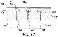
- the grooves 132 (and channels 130)may be re-entrant grooves 132 (re-entrant channels 130), as described below with reference to FIG. 12 .
- the side-walls of the grooves 132 (channels 130)need not be straight.
- the side-walls of the grooves 132 (channels 130)may be curved or rounded.
- each respective groove 132is wider than the top 136 thereof, such that each groove 132 comprises a re-entrant shaped groove 132.
- Re-entrant grooves 132are discussed in commonly assigned, US Patent Application Ser. No. 12/943,624, Bunker et al. , "Components with re-entrant shaped cooling channels and methods of manufacture," which is incorporated by reference herein in its entirety.
- the coatingwill bridge the top 136 of the groove, and the sacrificial filler 32 will be relatively easy to remove.
- the base 134 of a respective one of the re-entrant shaped grooves 132is at least 2 times wider than the top 136 of the respective groove 132.
- the top 136would be less than 0.375 millimeters in width, for this configuration.
- the base 134 of the respective re-entrant shaped groove 132is at least 3 times wider than the top 136 of the respective groove 132, and still more particularly, the base 134 of the respective re-entrant shaped groove 132 is in a range of about 3-4 times wider than the top 136 of the respective groove 132.
- a large base to top ratioincreases the overall cooling volume for the micro-channel 130.
- the coating 150completely bridges the respective grooves 132, such that the coating 150 seals the respective cooling channels 130.
- the permanent fillermay comprise a plurality of metal particles integrally connected to a surface 152 (indicated in FIG. 7 ) of the coating 150 (instead of forming a continuous permanent layer 33) and the coating 150 may define one or more porous gaps (also termed "permeable slots"), for example, porosity in the coating 150 or a gap in the coating, such that the coating 150 does not completely bridge each of the respective grooves 132.
- re-entrant shaped groovesmay also be advantageously coated using the multiple fillers of the process shown in FIGS. 3-9 of the present application.
- the fillersmay be used to make sure that the coating bridges the top of the groove, with only a relatively simple removal process needed for the readily removable sacrificial filler 32 (and optionally additional filler 35).
- the component 100includes a substrate 110 comprising an outer surface 112 and an inner surface 116.
- the outer surface 112defines one or more grooves 132, as indicated in FIG. 3 , for example.
- the grooves 132may be formed either by removing material from the substrate 110, as indicated in FIG. 3 , or by adding material to the substrate 110 on either side of the grooves, as indicated in FIG. 10 .
- each groove 132extends at least partially along the outer surface 112 of the substrate 110 and has a base 134.
- the component 100further includes a permanent filler 33 disposed within and extending across a top 136 of each of the one or more grooves 132 and a coating 150 disposed over at least a portion of the substrate 110 and over the permanent filler 33.
- the permanent filler 33further extends over at least a portion of the outer substrate surface 112.
- the groove(s) 132 and the permanent filler 33 and/or coating 150together define one or more channels 130 for cooling the component 100.
- the permanent filler 33comprises at least one of tungsten, nickel, cobalt, molybdenum, chromium, aluminum, and alloys thereof.
- the permanent filler 33comprises a continuous layer, such that the groove(s) 132 and the permanent filler 33 together define the cooling channel(s) 130.
- the permanent filler 33comprises a plurality of metal particles integrally connected to a surface 152 of the coating 150.
- the inner surface 116 of the substrate 110defines at least one hollow, interior space 114, and one or more access holes 140 extend through the base 134 of a respective one of the groove(s) 132 to place the groove 132 in fluid communication with the respective hollow interior space 114.
- the groovesneed not be rectangular but rather may take a number of shapes, depending on the requirement for the specific application.
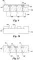
- the groovesmay be re-entrant shaped, as indicated in FIG. 16 , for example.
- the permanent filler 33extends across the top of the re-entrant shaped groove, such that the coating bridges the groove.
- a permanent filler 33simplifies the material removal process for the filler and provides a robust permanent layer to support the coating 150 during its deposition.
- this method of fabricating a component 100includes forming one or more grooves 132 in an outer surface 112 of a substrate 110.
- Each groove 132has a base 134 and a top 136 and extends at least partially along the outer surface 112 of the substrate 110.
- the grooves 132may be formed either by removing material from the substrate 110, as indicated in FIG. 3 , or by adding material to the substrate 110 on either side of the grooves, as indicated in FIG. 10 . This step is described in more detail above with reference to FIGS. 3 and 10 . As indicated in FIG.
- this component fabrication methodfurther includes disposing a filler 33 within the one or more grooves 132, such that a gap 37 (for example, an air gap) is formed between the filler 33 and the base 134 of the respective groove 132. As indicated, for example in FIG. 9 , this component fabrication method further includes disposing a coating 150 over at least a portion of the substrate 110 and over the filler 33. Example coating materials and deposition techniques are provided above.
- the filler 33forms a permanent layer 33 that is not removed from the channels 130, such that the gap 37 defines the respective cooling channel 130.
- the resulting componentis shown in FIG. 9 .
- the groove(s) 132 and the (permanent) filler 33together define one or more channels 130 for cooling the component 100.
- the (permanent) filler 33comprises at least one of tungsten, nickel, cobalt, molybdenum, chromium, aluminum, and alloys thereof.
- a metal foilmay be pressed or rolled on the surface to just fill the upper portion of the grooves, but also give a well defined fill depth over the air gap.
- this configurationprovides a robust, permanent layer 33 for supporting the coating 150 during its deposition, while eliminating the need for a potentially difficult and time consuming leaching process.
- the filler 33comprises a sacrificial filler 33
- the component fabrication methodfurther includes at least partially removing the filler 33 after disposing the coating 150, such that the coating 150 extends over the groove(s) 132, and the groove(s) 132 and the coating 150 together define one or more channels 130 for cooling the component 100.
- Example sacrificial fillers for use with this air-gap embodimentinclude copper wire, aluminum wire and copper ink. Suitable removal processes for these fillers include the application of concentrated nitric acid, 50% caustic soda and concentrated nitric acid, respectively.
- the component fabrication methodmay further include forming one or more access holes 140 through the base 134 of a respective groove 132 to connect the respective groove 132 in fluid communication with the respective hollow interior space 114. As indicated in FIG. 15 , the access holes 140 are typically formed prior to depositing the filler 33.
- the groovesneed not be rectangular but rather may take a number of shapes, depending on the requirement for the specific application.
- the groovesmay be re-entrant shaped, as indicated in FIG. 16 and 17 , for example.
- the filler 33extends across the top of the re-entrant shaped groove 132, as indicated in FIG. 17 , for example, such that the coating 150 bridges the groove 132, as shown in FIG. 18 .
- the fabrication methodincludes forming one or more grooves 132 in an outer surface 112 of a substrate 110.
- each groove 132has a base 134 and extends at least partially along the outer surface 112 of the substrate 110.
- the substrate, the grooves, and the formation of the groovesare described above.
- the grooves 132may be formed either by removing material from the substrate 110, as indicated in FIG. 3 or by adding material to the substrate 110 on either side of the desired grooves, as indicated in FIG. 10 .
- the component fabrication methodfurther includes disposing a sacrificial filler 32 within the one or more grooves 132 and disposing a second filler 33 over the sacrificial filler 32 and over at least a portion of the outer surface 112 of the substrate 110.
- the component fabrication methodfurther includes disposing a coating 150 over the second filler 33, such that the coating extends above at least a portion of the substrate 110 and removing the first sacrificial filler 32 from the one or more grooves 132 and partially removing the second filler 33, to define one or more channels 130 for cooling the component 100.
- the sacrificial filler 32comprises at least one material selected from the group consisting of wax, resin, metal alloy, graphite and combinations thereof, and the sacrificial filler 32 is removed by melting, evaporating, pyrolizing, leaching or oxidizing the sacrificial filler 32 out of the groove(s) 132.
- the second filler 33comprises at least one metal or metal alloy, and the second filler 33 is partially removed by leaching.
- the above-described methodsprovide improved means for depositing a coating over a grooved substrate to form a component with cooling channels.
- the above-described methodsmake it easier to provide a robust filler that can withstand the coating process.
- the methods that include the use of a sacrificial fillerprovide for easier removal of the sacrificial filler, while the methods that use only a permanent filler eliminate the need for a filler removal process. By simplifying (or eliminating) the removal process for the filler(s), these methods reduce the time and hence manufacturing costs for forming cooling channels within coated components.
Landscapes
- Chemical & Material Sciences (AREA)
- Engineering & Computer Science (AREA)
- Mechanical Engineering (AREA)
- Organic Chemistry (AREA)
- Chemical Kinetics & Catalysis (AREA)
- Materials Engineering (AREA)
- Metallurgy (AREA)
- Plasma & Fusion (AREA)
- Physics & Mathematics (AREA)
- General Engineering & Computer Science (AREA)
- Computer Hardware Design (AREA)
- Microelectronics & Electronic Packaging (AREA)
- Turbine Rotor Nozzle Sealing (AREA)
- Laminated Bodies (AREA)
Description
- The invention relates generally to gas turbine engines, and, more specifically, to micro-channel cooling therein.
- In a gas turbine engine, air is pressurized in a compressor and mixed with fuel in a combustor for generating hot combustion gases. Energy is extracted from the gases in a high pressure turbine (HPT), which powers the compressor, and in a low pressure turbine (LPT), which powers a fan in a turbofan aircraft engine application, or powers an external shaft for marine and industrial applications.
- Engine efficiency increases with temperature of combustion gases. However, the combustion gases heat the various components along their flowpath, which in turn requires cooling thereof to achieve a long engine lifetime. Typically, the hot gas path components are cooled by bleeding air from the compressor. This cooling process reduces engine efficiency, as the bled air is not used in the combustion process.
- Gas turbine engine cooling art is mature and includes numerous patents for various aspects of cooling circuits and features in the various hot gas path components. For example, the combustor includes radially outer and inner liners, which require cooling during operation. Turbine nozzles include hollow vanes supported between outer and inner bands, which also require cooling. Turbine rotor blades are hollow and typically include cooling circuits therein, with the blades being surrounded by turbine shrouds, which also require cooling. The hot combustion gases are discharged through an exhaust which may also be lined, and suitably cooled.
- In all of these exemplary gas turbine engine components, thin metal walls of high strength superalloy metals are typically used for enhanced durability while minimizing the need for cooling thereof. Various cooling circuits and features are tailored for these individual components in their corresponding environments in the engine. For example, a series of internal cooling passages, or serpentines, may be formed in a hot gas path component. A cooling fluid may be provided to the serpentines from a plenum, and the cooling fluid may flow through the passages, cooling the hot gas path component substrate and coatings. However, this cooling strategy typically results in comparatively low heat transfer rates and non-uniform component temperature profiles.
- Micro-channel cooling has the potential to significantly reduce cooling requirements by placing the cooling as close as possible to the heated region, thus reducing the temperature difference between the hot side and cold side of the main load bearing substrate material for a given heat transfer rate. Currently, a sacrificial material is used to keep the structural coating from plugging the cooling channels during its application. Because cooling channels tend to have large ratios of length to hydraulic diameter, the filler removal process is typically time-consuming and hence expensive and further can be subject to incomplete removal of the filler.
- It would therefore be desirable to provide methods for depositing a structural coating over cooling channels that overcome the above-noted shortcomings of current techniques.
EP1211385 A2 is considered to be the closest prior art and discloses use of a filler material over a groove. - One aspect of the present invention resides in a method of fabricating a component as disclosed in independent method claim 1.
- Another aspect of the present invention resides in a component disclosed in
independent apparatus claim 10. - Embodiments of the present invention will now be described, by way of example only, with reference to the accompanying drawings in which:
FIG. 1 is a schematic illustration of a gas turbine system;FIG. 2 is a schematic cross-section of an example airfoil configuration with cooling channels, in accordance with aspects of the present invention;FIGS. 3-8 schematically illustrate process steps for applying a coating to a substrate using multiple fillers;FIG. 9 schematically depicts, in cross-sectional view, three example cooling channels with a permanent filler layer remaining in the cooling channels;FIG. 10 illustrates another technique for forming grooves by adding material on the outer surface of the substrate on either side of the desired grooves;FIG. 11 schematically illustrates a process step using three fillers;FIG. 12 schematically illustrates a coated component with re-entrant shaped cooling channels and a permanent filler;FIG. 13 schematically depicts, in perspective view, three example cooling channels with a permanent filler, where the channels extend partially along the surface of the substrate and channel coolant to respective film cooling holes; andFIG. 14 is a cross-sectional view of one of the example cooling channels ofFIG. 12 and shows the channel conveying coolant from an access hole to a film cooling hole;FIG. 15 schematically illustrates a process step for applying a coating to a substrate using a filler with a gap formed between the filler and the base of the respective grooves; andFIG. 16-18 schematically illustrate process steps for applying a coating to a substrate with re-entrant shaped grooves using a permanent filler.- The terms "first," "second," and the like, herein do not denote any order, quantity, or importance, but rather are used to distinguish one element from another. The terms "a" and "an" herein do not denote a limitation of quantity, but rather denote the presence of at least one of the referenced items. The modifier "about" used in connection with a quantity is inclusive of the stated value, and has the meaning dictated by context, (e.g., includes the degree of error associated with measurement of the particular quantity). In addition, the term "combination" is inclusive of blends, mixtures, alloys, reaction products, and the like.
- Moreover, in this specification, the suffix "(s)" is usually intended to include both the singular and the plural of the term that it modifies, thereby including one or more of that term (e.g., "the passage hole" may include one or more passage holes, unless otherwise specified). Reference throughout the specification to "one embodiment," "another embodiment," "an embodiment," and so forth, means that a particular element (e.g., feature, structure, and/or characteristic) described in connection with the embodiment is included in at least one embodiment described herein, and may or may not be present in other embodiments. In addition, it is to be understood that the described inventive features may be combined in any suitable manner in the various embodiments.
FIG. 1 is a schematic diagram of agas turbine system 10. Thesystem 10 may include one ormore compressors 12,combustors 14,turbines 16, andfuel nozzles 20. Thecompressor 12 andturbine 16 may be coupled by one ormore shaft 18. Theshaft 18 may be a single shaft or multiple shaft segments coupled together to formshaft 18.- The
gas turbine system 10 may include a number of hotgas path components 100. A hot gas path component is any component of thesystem 10 that is at least partially exposed to a high temperature flow of gas through thesystem 10. For example, bucket assemblies (also known as blades or blade assemblies), nozzle assemblies (also known as vanes or vane assemblies), shroud assemblies, transition pieces, retaining rings, and compressor exhaust components are all hot gas path components. However, it should be understood that the hotgas path component 100 of the present invention is not limited to the above examples, but may be any component that is at least partially exposed to a high temperature flow of gas. Further, it should be understood that the hotgas path component 100 of the present disclosure is not limited to components ingas turbine systems 10, but may be any piece of machinery or component thereof that may be exposed to high temperature flows. - When a hot
gas path component 100 is exposed to a hot gas flow, the hotgas path component 100 is heated by the hot gas flow and may reach a temperature at which the hotgas path component 100 fails. Thus, in order to allowsystem 10 to operate with hot gas flow at a high temperature, increasing the efficiency and performance of thesystem 10, a cooling system for the hotgas path component 100 is required. - In general, the cooling system of the present disclosure includes a series of small channels, or micro-channels, formed in the surface of the hot
gas path component 100. For industrial sized power generating turbine components, "small" or "micro" channel dimensions would encompass approximate depths and widths in the range of 0.25 mm to 1.5 mm, while for aviation sized turbine components channel dimensions would encompass approximate depths and widths in the range of 0.15 mm to 0.5 mm. The hot gas path component may be provided with a cover layer. A cooling fluid may be provided to the channels from a plenum, and the cooling fluid may flow through the channels, cooling the cover layer. - A method of fabricating a
component 100 is described with reference toFIGS. 2-14 . As indicated, for example inFIGS. 3 and10 , the component fabrication method includes forming one ormore grooves 132 in anouter surface 112 of asubstrate 110. As indicated inFIGS. 13 and 14 , for example, eachgroove 132 has abase 134 and extends at least partially along theouter surface 112 of thesubstrate 110. Thegrooves 132 may be formed either by removing material from thesubstrate 110, as indicated inFIG. 3 or by adding material to thesubstrate 110 on either side of the desired grooves, as indicated inFIG. 10 .US Patent 6,921,014, Hasz et al. , "Method for forming a channel on the surface of a metal substrate," describes techniques for forming grooves by adding material to thesubstrate 110 and is incorporated by reference herein in its entirety. For the example arrangement shown inFIG. 2 , thesubstrate 110 has at least one hollowinterior space 114. - The
substrate 110 is typically cast prior to forminggrooves 132 in theouter surface 112 of thesubstrate 110. As discussed in commonly assignedUS Patent No. 5,626,462, Melvin R. Jackson et al. , "Double-Wall Airfoil," which is incorporated by reference herein in its entirety,substrate 110 may be formed from any suitable material. Depending on the intended application forcomponent 100, this could include Ni-base, Co-base and Fe-base superalloys. The Ni-base superalloys may be those containing both γ and γ' phases, particularly those Ni-base superalloys containing both γ and γ' phases wherein the γ' phase occupies at least 40% by volume of the superalloy. Such alloys are known to be advantageous because of a combination of desirable properties including high temperature strength and high temperature creep resistance. The substrate material may also comprise a NiAl intermetallic alloy, as these alloys are also known to possess a combination of superior properties including high temperature strength and high temperature creep resistance that are advantageous for use in turbine engine applications used for aircraft. In the case of Nb-base alloys, coated Nb-base alloys having superior oxidation resistance will be preferred, particularly those alloys comprising Nb-(27-40)Ti-(4.5-10.5)Al-(4.5-7.9)Cr-(1.5-5.5)Hf-(0-6)V, where the composition ranges are in atom per cent. The substrate material may also comprise a Nb-base alloy that contains at least one secondary phase, such as a Nb-containing intermetallic compound comprising a silicide, carbide or boride. Such alloys are composites of a ductile phase (i.e., the Nb-base alloy) and a strengthening phase (i.e., a Nb-containing intermetallic compound). For other arrangements, the substrate material comprises a molybdenum based alloy, such as alloys based on molybdenum (solid solution) with Mo5SiB2 and Mo3Si second phases. For other configurations, the substrate material comprises a ceramic matrix composite, such as a silicon carbide (SiC) matrix reinforced with SiC fibers. For other configurations the substrate material comprises a TiAl-based intermetallic compound. - As indicated, for example, in
FIGS. 5 and6 , the component fabrication method further includes disposing asacrificial filler 32 within the groove(s) 132 and depositing apermanent filler 33 over thesacrificial filler 32. Thepermanent filler 33 may be disposed within the groove(s) 132 or may extend over at least a portion of theouter surface 112 of thesubstrate 110. Suitable materials forfillers FIGS. 6 and 7 , in practice this interface may be rough and/or may include voids. As indicated inFIGS. 7-9 , for example, the component fabrication method further includes disposing acoating 150 over at least a portion of thesubstrate 110 and over thepermanent filler 33 and removing thesacrificial filler 32 from the groove(s) 132, such that the groove(s) 132 and the permanent filler 33 (orcoating 150 if thepermanent filler 33 forms an integral part of the coating, as discussed below) together define one ormore channels 130 for cooling thecomponent 100. Suitable materials forcoating 150 are provided below. Although the grooves are shown as having straight walls, thegrooves 132 can have any configuration, for example, they may be straight, curved, or have multiple curves. - As indicated in
FIGS. 13 and 14 , for example, thesubstrate 110 and thecoating 150 may further define one or more exit film holes 142. For particular processes, the film holes 142 may be formed, for example by drilling, prior to removal of thefillers FIGS. 13 and 14 , the coolingchannel 130 conveys coolant from therespective access hole 140 to the exitingfilm cooling hole 142. However, other configurations do not entail a film hole, with the cooling channels simply extending along thesubstrate surface 112 and exiting off an edge of the component, such as the trailing edge or the bucket tip, or an endwall edge. In addition, it should be noted that although the film holes are shown inFIG. 13 as being round, this is a non-limiting example. The film holes may also be non-circular shaped holes. - Coating 150 comprises a suitable material and is bonded to the airfoil-shaped
outer surface 112 ofsubstrate 110 and/or to thepermanent filler 33 if the permanent filler extends over at least a portion of theouter surface 112 ofsubstrate 110. For particular configurations, thecoating 150 has a thickness in the range of 0.1-2.0 millimeters, and more particularly, in the range of 0.1 to 1 millimeter, and still more particularly 0.1 to 0.5 millimeters for industrial components. For aviation components, this range is typically 0.1 to 0.25 millimeters. However, other thicknesses may be utilized depending on the requirements for aparticular component 100. - The
coating 150 comprises structural coating layers and may further include optional additional coating layer(s). The coating layer(s) may be deposited using a variety of techniques. For particular processes, the structural coating layer(s) are deposited by performing an ion plasma deposition (cathodic arc). Example ion plasma deposition apparatus and method are provided in commonly assigned,US Published Patent Application No. 20080138529, Weaver et al , "Method and apparatus for cathodic arc ion plasma deposition," which is incorporated by reference herein in its entirety. Briefly, ion plasma deposition comprises placing a cathode formed of a coating material into a vacuum environment within a vacuum chamber, providing asubstrate 110 within the vacuum environment, supplying a current to the cathode to form a cathodic arc upon a cathode surface resulting in arc-induced erosion of coating material from the cathode surface, and depositing the coating material from the cathode upon thesubstrate surface 112. - Non-limiting examples of a coating deposited using ion plasma deposition include structural coatings, as well as bond coatings and oxidation-resistant coatings, as discussed in greater detail below with reference to
US Patent No. 5,626,462 . For certain hotgas path components 100, the structural coating comprises a nickel-based or cobalt-based alloy, and more particularly comprises a superalloy or a (NiCo)CrAlY alloy. For example, where the substrate material is a Ni-base superalloy containing both γ and γ' phases, structural coating may comprise similar compositions of materials, as discussed in greater detail below with reference toUS Patent No. 5,626,462 . - For other process configurations, the structural coating is deposited by performing at least one of a thermal spray process and a cold spray process. For example, the thermal spray process may comprise combustion spraying or plasma spraying, the combustion spraying may comprise high velocity oxygen fuel spraying (HVOF) or high velocity air fuel spraying (HVAF), and the plasma spraying may comprise atmospheric (such as air or inert gas) plasma spray, or low pressure plasma spray (LPPS, which is also know as vacuum plasma spray or VPS). In one non-limiting example, a NiCrAlY coating is deposited by HVOF or HVAF. Other example techniques for depositing the structural coating include, without limitation, sputtering, electron beam physical vapor deposition, electroless plating, and electroplating.
- For certain configurations, it is desirable to employ multiple deposition techniques for depositing structural and optional additional coating layers. For example, a first structural coating layer may be deposited using an ion plasma deposition, and a subsequently deposited layer and optional additional layers (not shown) may be deposited using other techniques, such as a combustion spray process or a plasma spray process. Depending on the materials used, the use of different deposition techniques for the coating layers may provide benefits in properties, such as, but not restricted to strain tolerance, strength, adhesion, and/or ductility.
- The
grooves 132 may be formed using a variety of techniques. For example, thegrooves 132 may be formed using one or more of an abrasive liquid jet, plunge electrochemical machining (ECM), electric discharge machining with a spinning single point electrode (milling EDM), and laser machining (laser drilling). Example laser machining techniques are described in commonly assigned,US Patent Application Ser. No. 12/697,005 US Patent Application Ser. No. 12/790,675 - For particular process configurations, the
grooves 132 are formed by directing anabrasive liquid jet 160 at theouter surface 112 of thesubstrate 110, as schematically depicted inFIG. 3 . Example water jet drilling processes and systems are provided inUS Patent Application Ser. No. 12/790,675 . As explained inUS Patent Application Ser. No. 12/790,675 , the water jet process typically utilizes a high-velocity stream of abrasive particles (e.g., abrasive "grit"), suspended in a stream of high pressure water. The pressure of the water may vary considerably, but is often in the range of about 35-620 MPa. A number of abrasive materials can be used, such as garnet, aluminum oxide, silicon carbide, and glass beads. - In addition, and as explained in
US Patent Application Ser. No. 12/790,675 , the water jet system can include a multi-axis computer numerically controlled (CNC) unit. The CNC systems themselves are known in the art, and described, for example, inU.S. Patent Publication 2005/0013926 (S. Rutkowski et al ), which is incorporated herein by reference. CNC systems allow movement of the cutting tool along a number of X, Y, and Z axes, as well as rotational axes. - For the example process shown in
FIG. 4 , the component fabrication method further includes forming one ormore access holes 140 through thebase 134 of a respective one of thegrooves 132 to provide fluid communication between thegrooves 132 and the hollow interior space(s) 114. The access holes 140 are typically formed prior to depositing thesacrificial filler 32. However, for certain processes, the access holes may be formed after depositing the sacrificial filler, namely by drilling through the sacrificial filler as well as the substrate. The access holes 140 are typically circular or oval in cross-section and may be formed, for example using on or more of laser machining (laser drilling), abrasive liquid jet, electric discharge machining (EDM) and electron beam drilling. The access holes 140 may be normal to thebase 134 of the respective grooves 132 (as shown inFIG. 13 , for example) or, more generally, may be drilled at angles in a range of 20-90 degrees relative to thebase 134 of the groove. The access holes 140 may be used to leach thesacrificial filler 32 from the channels after thecoating 150 has been deposited. - For the example shown in
FIGS. 8 and9 , thesacrificial filler 32 is removed from the groove(s) 132, such that the groove(s) 132 and thesecond filler 33 together define one ormore channels 130 for cooling thecomponent 100. Namely, for particular processes, thepermanent filler 33 forms a permanent layer 33 (either within the groove(s) or extending at least partially across theouter surface 112 of substrate 110) that is not removed from thechannels 130, such that the groove(s) 132 and the permanent filler 33 (and/or coating 150) together define the cooling channel(s) 130, as shown inFIG. 9 , for example. Depending on the application, a variety of materials may be used for the first and secondsacrificial fillers FIG. 5 , for particular arrangements, thesacrificial filler 32 comprises at least one material selected from the group consisting of wax, resin, metal alloy, graphite and combinations thereof. Non-limiting examples of suitable resins, include epoxy and photo-curable resins (for example, visible or UV curable resins), non-limiting examples of which include a UV/visible light curable masking resin, marketed under the trademark Speedmask 729® by DYMAX, having a place of business in Torrington, Connecticut. If a resin is used, the method further includes the optional step of curing theresin 32 prior to depositing thepermanent filler 33. Non-limiting example metal alloys include metal alloys with low melting temperatures (for example less than about 300° C), such as solders, for example lead bismuth, tin lead, lead tin bismuth, and indium lead solders. - For more particular arrangements, the
sacrificial filler 32 comprises wax or resin and further comprises an electrically conductive particulate phase, such as powders, flakes, and whiskers, dispersed within the wax or resin. By using an electrically conductivesacrificial filler 32, thepermanent filler 33 may be deposited by electroplating or ion plasma deposition. For example, the wax or resin base may be loaded with a graphite or aluminum powder, so that thepermanent filler 33 can be electroplated over the first sacrificial filler. - For particular configurations, the
permanent filler 33 comprises at least one metal. For example, thepermanent filler 33 may comprises at least one of tungsten, nickel, cobalt, molybdenum, chromium, aluminum, and alloys thereof. The metal may be deposited using a metal ink, a solid metal filler, by electroplating or by electroless deposition. Non-limiting examples of deposition techniques for themetal layer 33 include using a syringe or direct write technique to deposit a metal ink, for example molybdenum or tungsten ink particles dispersed in a resin binder. For example, tungsten and/or molybdenum may be deposited in the form of a metal ink using a syringe or direct write, in which case the method further includes the additional optional step of curing the metal ink prior to depositing thecoating 150. - For other processes, a solid metal filler may be used, for example an annealed metal wire, as described in commonly assigned
US Patent No. 12/953,177, Ronald S. Bunker et al. sacrificial filler 32. - For other processes, a
metal layer 33 may be deposited by electroplating or by electroless deposition. For example, molybdenum may be deposited using an electroless technique. For certain processes, molybdenum may be deposited by physical vapor deposition, for example by sputtering, evaporation, and ion plasma deposition. For other processes, nickel is deposited, for example by electroless plating, into the grooves and then left in the channels. - A variety of techniques may be employed to remove the
sacrificial filler 32 depending on the specific filler materials used. For certain configurations, thesacrificial filler 32 may be readily removable, for example by melting, evaporating, pyrolizing, or oxidizing thesacrificial filler 32 out of the groove(s) 132. For example, awax layer 32 may be removed by heating (for example, at about 100° C) or by being burned out (vaporized) at about 300° C. In addition, where residue remains after performing an initial removal process, the residue may be removed by pyrolysis. - For particular processes, the majority of the groove is filled with a readily removable
sacrificial filler 32 and a relatively small amount of thepermanent filler 33 is used. This facilitates the use of asecond filler 33 that can withstand polishing (for example, grit blast) or other operations performed prior to coating, as well as withstanding the coating process itself. For particular configurations, thesacrificial filler 32 is deposited within the groove(s) 132 to a partial fill in a range of about 60 - 99.9 percent of the depth of therespective groove 132, and thepermanent filler 33 is then deposited within the groove(s) 132 to at least a full fill of therespective groove 132. If the grooves are overfilled with thesecond material 33, the excess material may be removed, for example by application of a doctor blade or by polishing depending on the type offiller 33 used, prior to deposition of thecoating 150. - For particular configurations, the thickness of the
permanent filler 33 is less than about 500 microns. More particularly, the thickness of thepermanent layer 33 is less than about 200 microns, and still more particularly, is less than about 50 microns. Beneficially, by depositing a relatively thick layer of thesacrificial filler 32, which is relatively easy to remove but less robust to the coating process, with a relatively thin layer of the second,permanent filler 33, the resulting filler will be able to withstand the coating process with the bulk of the filler (namely, the sacrificial filler 32) being easily removed from the groove to leave a cooling channel defined by thegroove 132 and thepermanent filler 33. - For the example arrangement shown in
FIG. 11 , the component fabrication method further includes disposing at least oneadditional filler 35 within the one ormore grooves 132 before disposing thepermanent filler 33. For particular processes, thesacrificial filler 32 comprises wax, theadditional filler 35 comprises electroplated copper and thepermanent filler 33 comprises sputtered molybdenum. For this example, thesacrificial filler 32 may be removed by heating and theadditional filler 35 may be removed using concentrated nitric acid. For other example processes, thesacrificial filler 32 comprises copper wire, theadditional filler 35 comprises a resin, and thepermanent filler 33 comprises tungsten. - In addition, the method may further optionally include the application of an oxidation coating, such as PtAl (for example for aviation components) or an MCrAlY coating, where M is selected from cobalt, nickel, or iron (for example, for stationary power generation components), to the interior surfaces of the cooling
channels 130. For particular processes, the oxidation coating (not shown) may be applied after thefillers - For particular processes, the
permanent filler 33 comprises an electricallyconductive material 33, and the step of disposing thepermanent filler 33 comprises at least partially covering thesacrificial filler 32 with an electricallyconductive material 33. For this process, thecoating 150 may be deposited using an ion plasma or by electroplating. Ion plasma deposition is described above. More particularly, the electricallyconductive material 33 may comprise an electrically conductiveparticulate phase 33, such as powders, flakes, and whiskers. For particular processes, the electrically conductive particulate phase is sprinkled over thesacrificial filler 32 with a surface area coverage of at least about thirty percent, and more particularly, of at least about fifty percent. For particular processes, the electrically conductiveparticulate phase 33 is sprinkled over thesacrificial filler 32 with a surface area coverage of at least about thirty percent, more particularly, of at least about fifty percent, and still more particularly about one hundred percent. - A number of materials can be used for the electrically conductive
particulate phase 33 depending on the substrate and coating composition. For example nickel or molybdenum particulate phase may be used. For example processes, thesacrificial filler 32 applied in thegrooves 132 is wet, such that the electrically conductiveparticulate phase 33 sticks to the wetsacrificial filler 32. The electrically conductive particulate phase improves the coating coverage from an ion plasma coating process by allowing for high energy metallic ions to adhere to the conductive particulate phase. Once an initial consistent layer is generated, the subsequent ions from the cathode build up on this metallic layer and thicken it. For this process, the conductiveparticulate phase 33 may take the form of plurality of metal particles integrally connected to asurface 152 of thecoating 150, rather than forming a continuous permanent layer. - A number of
sacrificial fillers 32 may be used with in this process. Desirably, the sacrificial filler will have minimal shrinkage at the relevant coating deposition temperatures and will withstand temperatures of less than about 550° C, for example. One example class ofsuitable filler 32 materials includes commercially available low shrinkage joint compounds. Beneficially, these materials may be removed after the coating deposition by mechanical agitation and application of hot water. In one non-limiting example, a joint compound marketed under the tradename Durabond-90®, which is commercially availably from US Gypsum, was used as a sacrificial filler, and nickel powder was sprinkled over the wet joint compound to a coverage of about 100%. A nickel basedcoating 150 was deposited by ion plasma deposition, and the joint compound was then removed by mechanical agitation and application of hot water. - In addition to being deposited over a
sacrificial filler 32, an electrically conductiveparticulate phase 33 may be scattered over anadditional filler 35, such that thecoating 150 can be deposited using an ion plasma over an electrically non-conductingadditional filler 35. - Although, the process described above with reference to
FIGS. 3-9 is shown as havingrectangular grooves 132, the grooves may have a variety of shapes depending on the requirements of the specific application. For example, the grooves 132 (and channels 130) may be re-entrant grooves 132 (re-entrant channels 130), as described below with reference toFIG. 12 . In addition, the side-walls of the grooves 132 (channels 130) need not be straight. For various applications, the side-walls of the grooves 132 (channels 130) may be curved or rounded. - For the example configuration shown in
FIG. 12 , thebase 134 of eachrespective groove 132 is wider than the top 136 thereof, such that eachgroove 132 comprises a re-entrant shapedgroove 132.Re-entrant grooves 132 are discussed in commonly assigned,US Patent Application Ser. No. 12/943,624, Bunker et al. , "Components with re-entrant shaped cooling channels and methods of manufacture," which is incorporated by reference herein in its entirety. Beneficially, by filling re-entrant shapedgrooves 132 with a more readily removable sacrificial filler that is covered with a second permanent filler 33 (FIG. 12 ), the coating will bridge the top 136 of the groove, and thesacrificial filler 32 will be relatively easy to remove. - For particular configurations, the
base 134 of a respective one of the re-entrant shapedgrooves 132 is at least 2 times wider than the top 136 of therespective groove 132. For example, if thebase 134 of thegroove 132 is 0.75 millimeters, the top 136 would be less than 0.375 millimeters in width, for this configuration. For more particular configurations, thebase 134 of the respective re-entrant shapedgroove 132 is at least 3 times wider than the top 136 of therespective groove 132, and still more particularly, thebase 134 of the respective re-entrant shapedgroove 132 is in a range of about 3-4 times wider than the top 136 of therespective groove 132. Beneficially, a large base to top ratio increases the overall cooling volume for the micro-channel 130. - As discussed in
US Patent Application Ser. No. 12/943,624 , with reference toFIGS. 7 and11 ofUS Ser. No. 12/943,624 coating 150 completely bridges therespective grooves 132, such that thecoating 150 seals therespective cooling channels 130. For other arrangements, the permanent filler may comprise a plurality of metal particles integrally connected to a surface 152 (indicated inFIG. 7 ) of the coating 150 (instead of forming a continuous permanent layer 33) and thecoating 150 may define one or more porous gaps (also termed "permeable slots"), for example, porosity in thecoating 150 or a gap in the coating, such that thecoating 150 does not completely bridge each of therespective grooves 132. Although the methods taught inUS Patent Application Ser. No. 12/943,624 deposit a coating without the use of fillers, re-entrant shaped grooves may also be advantageously coated using the multiple fillers of the process shown inFIGS. 3-9 of the present application. For example, the fillers may be used to make sure that the coating bridges the top of the groove, with only a relatively simple removal process needed for the readily removable sacrificial filler 32 (and optionally additional filler 35). - A
component 100 embodiment of the invention is described with reference toFIGS. 3 ,9 ,10 ,13 ,14 , and16 . As indicated, for example, inFIG. 9 , thecomponent 100 includes asubstrate 110 comprising anouter surface 112 and aninner surface 116. Theouter surface 112 defines one ormore grooves 132, as indicated inFIG. 3 , for example. As noted above, thegrooves 132 may be formed either by removing material from thesubstrate 110, as indicated inFIG. 3 , or by adding material to thesubstrate 110 on either side of the grooves, as indicated inFIG. 10 . As shown, for example, inFIG. 13 , eachgroove 132 extends at least partially along theouter surface 112 of thesubstrate 110 and has abase 134. As indicated inFIGS. 9 ,13 and 14 , thecomponent 100 further includes apermanent filler 33 disposed within and extending across a top 136 of each of the one ormore grooves 132 and acoating 150 disposed over at least a portion of thesubstrate 110 and over thepermanent filler 33. For certain configurations, thepermanent filler 33 further extends over at least a portion of theouter substrate surface 112. As indicated inFIG. 9 , the groove(s) 132 and thepermanent filler 33 and/orcoating 150 together define one ormore channels 130 for cooling thecomponent 100. - Example materials and deposition techniques for
permanent filler 33 are provided above. For example configurations, thepermanent filler 33 comprises at least one of tungsten, nickel, cobalt, molybdenum, chromium, aluminum, and alloys thereof. For the illustrated examples, thepermanent filler 33 comprises a continuous layer, such that the groove(s) 132 and thepermanent filler 33 together define the cooling channel(s) 130. For other configurations, thepermanent filler 33 comprises a plurality of metal particles integrally connected to asurface 152 of thecoating 150. - As shown in
FIG. 9 and as described above, for example configurations, theinner surface 116 of thesubstrate 110 defines at least one hollow,interior space 114, and one ormore access holes 140 extend through thebase 134 of a respective one of the groove(s) 132 to place thegroove 132 in fluid communication with the respective hollowinterior space 114. - As discussed above, the grooves need not be rectangular but rather may take a number of shapes, depending on the requirement for the specific application. For particular configurations, the grooves may be re-entrant shaped, as indicated in
FIG. 16 , for example. For this configuration, thepermanent filler 33 extends across the top of the re-entrant shaped groove, such that the coating bridges the groove. - Beneficially, the use of a
permanent filler 33 simplifies the material removal process for the filler and provides a robust permanent layer to support thecoating 150 during its deposition. - Another component fabrication method is described with reference to
FIGS. 3, 4 ,9, 10 and15-18 . As indicated, for example, inFIGS. 3 and10 , this method of fabricating acomponent 100 includes forming one ormore grooves 132 in anouter surface 112 of asubstrate 110. Eachgroove 132 has abase 134 and a top 136 and extends at least partially along theouter surface 112 of thesubstrate 110. As noted above, thegrooves 132 may be formed either by removing material from thesubstrate 110, as indicated inFIG. 3 , or by adding material to thesubstrate 110 on either side of the grooves, as indicated inFIG. 10 . This step is described in more detail above with reference toFIGS. 3 and10 . As indicated inFIG. 15 , this component fabrication method further includes disposing afiller 33 within the one ormore grooves 132, such that a gap 37 (for example, an air gap) is formed between thefiller 33 and thebase 134 of therespective groove 132. As indicated, for example inFIG. 9 , this component fabrication method further includes disposing acoating 150 over at least a portion of thesubstrate 110 and over thefiller 33. Example coating materials and deposition techniques are provided above. - For some configurations of the method illustrated by
FIGS. 9 and15 , thefiller 33 forms apermanent layer 33 that is not removed from thechannels 130, such that thegap 37 defines therespective cooling channel 130. For these configurations, the resulting component is shown inFIG. 9 . In other words, for these configurations, the groove(s) 132 and the (permanent)filler 33 together define one ormore channels 130 for cooling thecomponent 100. For particular configurations, the (permanent)filler 33 comprises at least one of tungsten, nickel, cobalt, molybdenum, chromium, aluminum, and alloys thereof. For example, a metal foil may be pressed or rolled on the surface to just fill the upper portion of the grooves, but also give a well defined fill depth over the air gap. Beneficially, this configuration provides a robust,permanent layer 33 for supporting thecoating 150 during its deposition, while eliminating the need for a potentially difficult and time consuming leaching process. - For other processes, such as those also illustrated by
FIG.15 , thefiller 33 comprises asacrificial filler 33, and the component fabrication method further includes at least partially removing thefiller 33 after disposing thecoating 150, such that thecoating 150 extends over the groove(s) 132, and the groove(s) 132 and thecoating 150 together define one ormore channels 130 for cooling thecomponent 100. Example sacrificial fillers for use with this air-gap embodiment include copper wire, aluminum wire and copper ink. Suitable removal processes for these fillers include the application of concentrated nitric acid, 50% caustic soda and concentrated nitric acid, respectively. - As discussed above with reference to
FIG. 4 , the component fabrication method may further include forming one ormore access holes 140 through thebase 134 of arespective groove 132 to connect therespective groove 132 in fluid communication with the respective hollowinterior space 114. As indicated inFIG. 15 , the access holes 140 are typically formed prior to depositing thefiller 33. - Similar to the methods described above, the grooves need not be rectangular but rather may take a number of shapes, depending on the requirement for the specific application. For particular configurations, the grooves may be re-entrant shaped, as indicated in
FIG. 16 and 17 , for example. For this configuration, thefiller 33 extends across the top of the re-entrant shapedgroove 132, as indicated inFIG. 17 , for example, such that thecoating 150 bridges thegroove 132, as shown inFIG. 18 . - Another component fabrication method is described with reference to
FIGS. 2-14 . As indicated, for example, inFIGS. 3 and10 , the fabrication method includes forming one ormore grooves 132 in anouter surface 112 of asubstrate 110. As shown for example inFIGS. 13 and 14 , eachgroove 132 has abase 134 and extends at least partially along theouter surface 112 of thesubstrate 110. The substrate, the grooves, and the formation of the grooves are described above. Thegrooves 132 may be formed either by removing material from thesubstrate 110, as indicated inFIG. 3 or by adding material to thesubstrate 110 on either side of the desired grooves, as indicated inFIG. 10 . - As indicated, for example, in
FIGS. 5 and6 , the component fabrication method further includes disposing asacrificial filler 32 within the one ormore grooves 132 and disposing asecond filler 33 over thesacrificial filler 32 and over at least a portion of theouter surface 112 of thesubstrate 110. As indicated, for example, inFIGS. 7-9 , the component fabrication method further includes disposing acoating 150 over thesecond filler 33, such that the coating extends above at least a portion of thesubstrate 110 and removing the firstsacrificial filler 32 from the one ormore grooves 132 and partially removing thesecond filler 33, to define one ormore channels 130 for cooling thecomponent 100. - Example filler materials and removal techniques are described above. For particular processes, the
sacrificial filler 32 comprises at least one material selected from the group consisting of wax, resin, metal alloy, graphite and combinations thereof, and thesacrificial filler 32 is removed by melting, evaporating, pyrolizing, leaching or oxidizing thesacrificial filler 32 out of the groove(s) 132. For particular processes, thesecond filler 33 comprises at least one metal or metal alloy, and thesecond filler 33 is partially removed by leaching. - Beneficially, the above-described methods provide improved means for depositing a coating over a grooved substrate to form a component with cooling channels. In particular, the above-described methods make it easier to provide a robust filler that can withstand the coating process. In addition, the methods that include the use of a sacrificial filler provide for easier removal of the sacrificial filler, while the methods that use only a permanent filler eliminate the need for a filler removal process. By simplifying (or eliminating) the removal process for the filler(s), these methods reduce the time and hence manufacturing costs for forming cooling channels within coated components.
Claims (14)
- A method of fabricating a component(100) of a gas turbine engine, the method comprising:forming one or more grooves (132) in an outer surface (112) of a substrate (110) having at least one interior space, wherein each of the one or more grooves (132) is defined by a base (134) and a plurality of sidewalls, each sidewall extending continuously from the base to an uppermost surface of the substrate and each of the one or more grooves (132) extends at least partially along the outer surface (112) of the substrate (110);forming one or more access holes (140) through the base of a respective one of the one or more grooves to connect the respective groove in fluid communication with the respective hollow interior space;disposing a sacrificial filler (32) within the one or more grooves (132) the sacrificial filler being in contact with the base (134) and the plurality of sidewalls of each of the one or more grooves;disposing a permanent filler (33) on the uppermost surface of the sacrificial filler (32) the permanent filler being only in contact with the uppermost surface of the sacrificial filler and the plurality of sidewalls of the one or more grooves and not in contact with the base of each of the one or more grooves;disposing a coating (150) over at least a portion of the substrate (110) and over the permanent filler (33); andremoving the sacrificial filler (32) from the one or more grooves (132), to define one or more channels (130) for cooling the component (100).
- The method of Claim 1, wherein the sacrificial filler (32) comprises at least one material selected from the group consisting of wax, resin, metal alloy, graphite, and combinations thereof.
- The method of Claim 2, wherein the sacrificial filler (32) comprises wax or resin and further comprises an electrically conductive particulate phase dispersed within the wax or resin, and wherein the permanent filler (33) is deposited by electroplating or ion plasma deposition.
- The method of Claim 2 or 3, wherein the sacrificial filler is removed by melting, evaporating, pyrolizing, oxidizing or leaching the sacrificial filler out of the one or more grooves.
- The method of any preceding Claim, wherein the permanent filler (33) comprises an electrically conductive material (33), wherein the step of disposing the permanent filler (33) over the sacrificial filler (32) comprises at least partially covering the sacrificial filler (32) with the electrically conductive material (33), wherein the step of disposing the coating (150) is performed by ion plasma deposition or electroplating, and wherein the electrically conductive material (33) comprises an electrically conductive particulate phase (33).
- The method of any preceding Claim, further comprising disposing at least one additional filler (35) within the one or more grooves (132) prior to disposing the permanent filler (33).
- The method of any preceding Claim, wherein the permanent filler comprises at least one of tungsten, nickel, cobalt, molybdenum, chromium, aluminum, and alloys thereof.
- The method of any preceding Claim, wherein a thickness of the permanent filler is less than about 500 microns.
- The method of any preceding Claim, wherein the sacrificial filler (32) is disposed within the at least one or more grooves (132) to a partial fill in a range of about 60 - 99.9 percent of the depth of the respective groove, and wherein the permanent filler (33) is disposed within the at least one or more grooves (132) to at least a full fill of the respective groove.
- A component (100) of a gas turbine engine comprising:a substrate (110) comprising an outer surface (112) and an inner surface (116), wherein the outer surface (112) defines one or more grooves (132) formed in the surface, wherein each of the one or more grooves (132) is defined by a base (134) and a plurality of sidewalls, each sidewall extending continuously from the base to an uppermost surface of the substrate and each of the one or more grooves (132) extends at least partially along the outer surface (112) of the substrate (110), wherein the inner surface (116) defines at least one hollow, interior space (114), and wherein one or more access holes (140) extend through the base (134) of a respective one of the one or more grooves (132) to place the groove (132) in fluid communication with respective ones of the at least one hollow interior space (114);a permanent filler (33) disposed within and extending across a top (136) of each of the one or more grooves (132), the permanent filler being only in contact with the plurality of sidewalls of the one or more grooves and not in contact with the base of each of the one or more grooves and the outer surface of the substrate; anda coating (150) disposed over at least a portion of the substrate (110) and over the permanent filler (33) disposed within the groove and extending across the top of each of the one or more grooves, wherein the one or more grooves (132) and the permanent filler (33) or coating (150) together define one or more channels (130) for cooling the component (100).
- The component of Claim 10, wherein each of the one or more grooves (132) has a top, and wherein the base (134) of the groove (132) is wider than the top, such that each of the one or more grooves (132) comprises a re-entrant shaped groove.
- The component (100) of Claim 10 or 11, wherein the permanent filler (33) comprises a continuous layer, such that the one or more grooves (132) and the permanent filler (33) together define the one or more cooling channels (130).
- The component (100) of any of Claims 10 to 12, wherein the permanent filler (33) comprises a plurality of metal particles integrally connected to a surface (152) of the coating (150)
- The component of any of Claims 10 to 13, wherein the permanent filler (33) further extends over at least a portion of the outer surface (112) of the substrate (110).
Applications Claiming Priority (1)
| Application Number | Priority Date | Filing Date | Title |
|---|---|---|---|
| US13/095,129US8601691B2 (en) | 2011-04-27 | 2011-04-27 | Component and methods of fabricating a coated component using multiple types of fillers |
Publications (3)
| Publication Number | Publication Date |
|---|---|
| EP2518270A2 EP2518270A2 (en) | 2012-10-31 |
| EP2518270A3 EP2518270A3 (en) | 2017-11-15 |
| EP2518270B1true EP2518270B1 (en) | 2019-02-27 |
Family
ID=46147266
Family Applications (1)
| Application Number | Title | Priority Date | Filing Date |
|---|---|---|---|
| EP12165553.4AActiveEP2518270B1 (en) | 2011-04-27 | 2012-04-25 | Component and methods of fabricating a coated component using multiple types of fillers |
Country Status (3)
| Country | Link |
|---|---|
| US (2) | US8601691B2 (en) |
| EP (1) | EP2518270B1 (en) |
| CN (1) | CN102758651B (en) |
Families Citing this family (38)
| Publication number | Priority date | Publication date | Assignee | Title |
|---|---|---|---|---|
| US8387245B2 (en)* | 2010-11-10 | 2013-03-05 | General Electric Company | Components with re-entrant shaped cooling channels and methods of manufacture |
| US8673397B2 (en) | 2010-11-10 | 2014-03-18 | General Electric Company | Methods of fabricating and coating a component |
| US8528208B2 (en)* | 2011-04-11 | 2013-09-10 | General Electric Company | Methods of fabricating a coated component using multiple types of fillers |
| US8601691B2 (en) | 2011-04-27 | 2013-12-10 | General Electric Company | Component and methods of fabricating a coated component using multiple types of fillers |
| US20120295061A1 (en)* | 2011-05-18 | 2012-11-22 | General Electric Company | Components with precision surface channels and hybrid machining method |
| US9206696B2 (en) | 2011-08-16 | 2015-12-08 | General Electric Company | Components with cooling channels and methods of manufacture |
| US20130086784A1 (en) | 2011-10-06 | 2013-04-11 | General Electric Company | Repair methods for cooled components |
| CH706090A1 (en)* | 2012-02-17 | 2013-08-30 | Alstom Technology Ltd | A method for manufacturing a near-surface cooling passage in a thermally highly stressed component and component with such a channel. |
| US9435208B2 (en)* | 2012-04-17 | 2016-09-06 | General Electric Company | Components with microchannel cooling |
| DE102013109116A1 (en) | 2012-08-27 | 2014-03-27 | General Electric Company (N.D.Ges.D. Staates New York) | Component with cooling channels and method of manufacture |
| US9238265B2 (en) | 2012-09-27 | 2016-01-19 | General Electric Company | Backstrike protection during machining of cooling features |
| US9200521B2 (en)* | 2012-10-30 | 2015-12-01 | General Electric Company | Components with micro cooled coating layer and methods of manufacture |
| US20140137408A1 (en)* | 2012-11-16 | 2014-05-22 | General Electric Company | Methods of fabricating and coating turbine components |
| US9476306B2 (en) | 2013-11-26 | 2016-10-25 | General Electric Company | Components with multi-layered cooling features and methods of manufacture |
| DE102014200381A1 (en)* | 2014-01-13 | 2015-07-16 | Robert Bosch Gmbh | Method of generatively producing a turbine wheel with a shroud |
| US10731857B2 (en)* | 2014-09-09 | 2020-08-04 | Raytheon Technologies Corporation | Film cooling circuit for a combustor liner |
| US20160131364A1 (en)* | 2014-11-07 | 2016-05-12 | United Technologies Corporation | Combustor dilution hole cooling |
| US10132498B2 (en)* | 2015-01-20 | 2018-11-20 | United Technologies Corporation | Thermal barrier coating of a combustor dilution hole |
| CN104625655A (en)* | 2015-02-14 | 2015-05-20 | 杨光华 | Manufacturing method for curved hydraulic channel |
| US9828915B2 (en)* | 2015-06-15 | 2017-11-28 | General Electric Company | Hot gas path component having near wall cooling features |
| US9897006B2 (en)* | 2015-06-15 | 2018-02-20 | General Electric Company | Hot gas path component cooling system having a particle collection chamber |
| US9970302B2 (en) | 2015-06-15 | 2018-05-15 | General Electric Company | Hot gas path component trailing edge having near wall cooling features |
| US9938899B2 (en) | 2015-06-15 | 2018-04-10 | General Electric Company | Hot gas path component having cast-in features for near wall cooling |
| CA2935398A1 (en) | 2015-07-31 | 2017-01-31 | Rolls-Royce Corporation | Turbine airfoils with micro cooling features |
| US10731472B2 (en)* | 2016-05-10 | 2020-08-04 | General Electric Company | Airfoil with cooling circuit |
| US10415396B2 (en)* | 2016-05-10 | 2019-09-17 | General Electric Company | Airfoil having cooling circuit |
| US10704395B2 (en)* | 2016-05-10 | 2020-07-07 | General Electric Company | Airfoil with cooling circuit |
| US20170370375A1 (en)* | 2016-06-22 | 2017-12-28 | United Technologies Corporation | Fan blade filler |
| US20180111200A1 (en)* | 2016-10-20 | 2018-04-26 | General Electric Company | Porous film hole exit and method for making same |
| US10465526B2 (en) | 2016-11-15 | 2019-11-05 | Rolls-Royce Corporation | Dual-wall airfoil with leading edge cooling slot |
| US10648341B2 (en) | 2016-11-15 | 2020-05-12 | Rolls-Royce Corporation | Airfoil leading edge impingement cooling |
| JP6622176B2 (en)* | 2016-11-30 | 2019-12-18 | 三菱重工業株式会社 | High temperature components for gas turbines and gas turbines |
| US10450873B2 (en) | 2017-07-31 | 2019-10-22 | Rolls-Royce Corporation | Airfoil edge cooling channels |
| JP6972328B2 (en)* | 2017-10-13 | 2021-11-24 | ゼネラル・エレクトリック・カンパニイ | Coated components with adaptive cooling openings and methods of their manufacture |
| US10760889B2 (en) | 2018-09-12 | 2020-09-01 | United Technologies Corporation | Fan blade masking/coating check inspection tool |
| US10882158B2 (en)* | 2019-01-29 | 2021-01-05 | General Electric Company | Peening coated internal surfaces of turbomachine components |
| US11174738B1 (en)* | 2020-05-06 | 2021-11-16 | General Electric Company | Sacrificial plug system |
| US11548102B2 (en) | 2020-07-31 | 2023-01-10 | General Electric Company | Method for repairing composite components using a plug |
Family Cites Families (73)
| Publication number | Priority date | Publication date | Assignee | Title |
|---|---|---|---|---|
| IL70146A0 (en)* | 1982-12-22 | 1984-02-29 | Gen Electric | Article with a fluid passage and method for making it |
| US4487550A (en) | 1983-01-27 | 1984-12-11 | The United States Of America As Represented By The Secretary Of The Air Force | Cooled turbine blade tip closure |
| US4893987A (en) | 1987-12-08 | 1990-01-16 | General Electric Company | Diffusion-cooled blade tip cap |
| US5075966A (en)* | 1990-09-04 | 1991-12-31 | General Electric Company | Method for fabricating a hollow component for a rocket engine |
| US5660523A (en) | 1992-02-03 | 1997-08-26 | General Electric Company | Turbine blade squealer tip peripheral end wall with cooling passage arrangement |
| JP3137527B2 (en) | 1994-04-21 | 2001-02-26 | 三菱重工業株式会社 | Gas turbine blade tip cooling system |
| US5626462A (en) | 1995-01-03 | 1997-05-06 | General Electric Company | Double-wall airfoil |
| US5640767A (en) | 1995-01-03 | 1997-06-24 | Gen Electric | Method for making a double-wall airfoil |
| US6383602B1 (en) | 1996-12-23 | 2002-05-07 | General Electric Company | Method for improving the cooling effectiveness of a gaseous coolant stream which flows through a substrate, and related articles of manufacture |
| US5875549A (en) | 1997-03-17 | 1999-03-02 | Siemens Westinghouse Power Corporation | Method of forming internal passages within articles and articles formed by same |
| DE19737845C2 (en)* | 1997-08-29 | 1999-12-02 | Siemens Ag | Method for producing a gas turbine blade, and gas turbine blade produced using the method |
| FR2776215B1 (en)* | 1998-03-20 | 2000-06-16 | Snecma | PROCESS FOR MANUFACTURING A HIGH-THERMAL FLOW REGENERATIVE CIRCUIT, IN PARTICULAR FOR A FIREPLACE COMBUSTION CHAMBER |
| US6321449B2 (en) | 1998-11-12 | 2001-11-27 | General Electric Company | Method of forming hollow channels within a component |
| US6214248B1 (en)* | 1998-11-12 | 2001-04-10 | General Electric Company | Method of forming hollow channels within a component |
| US6059530A (en) | 1998-12-21 | 2000-05-09 | General Electric Company | Twin rib turbine blade |
| US6190129B1 (en) | 1998-12-21 | 2001-02-20 | General Electric Company | Tapered tip-rib turbine blade |
| US6086328A (en) | 1998-12-21 | 2000-07-11 | General Electric Company | Tapered tip turbine blade |
| US6231307B1 (en) | 1999-06-01 | 2001-05-15 | General Electric Company | Impingement cooled airfoil tip |
| EP1065026B1 (en) | 1999-06-03 | 2004-04-28 | ALSTOM Technology Ltd | Method for manufacturing or repairing cooling channels in single crystal gas turbine components |
| US6254756B1 (en)* | 1999-08-11 | 2001-07-03 | General Electric Company | Preparation of components having a partial platinum coating thereon |
| US6164914A (en) | 1999-08-23 | 2000-12-26 | General Electric Company | Cool tip blade |
| US6234755B1 (en) | 1999-10-04 | 2001-05-22 | General Electric Company | Method for improving the cooling effectiveness of a gaseous coolant stream, and related articles of manufacture |
| DE10024302A1 (en) | 2000-05-17 | 2001-11-22 | Alstom Power Nv | Process for producing a thermally stressed casting |
| US6368060B1 (en) | 2000-05-23 | 2002-04-09 | General Electric Company | Shaped cooling hole for an airfoil |
| US6617003B1 (en) | 2000-11-06 | 2003-09-09 | General Electric Company | Directly cooled thermal barrier coating system |
| US6427327B1 (en)* | 2000-11-29 | 2002-08-06 | General Electric Company | Method of modifying cooled turbine components |
| US6551061B2 (en) | 2001-03-27 | 2003-04-22 | General Electric Company | Process for forming micro cooling channels inside a thermal barrier coating system without masking material |
| US6461108B1 (en) | 2001-03-27 | 2002-10-08 | General Electric Company | Cooled thermal barrier coating on a turbine blade tip |
| US6461107B1 (en) | 2001-03-27 | 2002-10-08 | General Electric Company | Turbine blade tip having thermal barrier coating-formed micro cooling channels |
| US6494678B1 (en) | 2001-05-31 | 2002-12-17 | General Electric Company | Film cooled blade tip |
| US6602052B2 (en) | 2001-06-20 | 2003-08-05 | Alstom (Switzerland) Ltd | Airfoil tip squealer cooling construction |
| US6602053B2 (en) | 2001-08-02 | 2003-08-05 | Siemens Westinghouse Power Corporation | Cooling structure and method of manufacturing the same |
| EP1295969A1 (en) | 2001-09-22 | 2003-03-26 | ALSTOM (Switzerland) Ltd | Method of growing a MCrAIY-coating and an article coated with the MCrAIY-coating |
| EP1295970A1 (en) | 2001-09-22 | 2003-03-26 | ALSTOM (Switzerland) Ltd | MCrAlY type alloy coating |
| US6634860B2 (en) | 2001-12-20 | 2003-10-21 | General Electric Company | Foil formed structure for turbine airfoil tip |
| US6921014B2 (en) | 2002-05-07 | 2005-07-26 | General Electric Company | Method for forming a channel on the surface of a metal substrate |
| EP1365039A1 (en)* | 2002-05-24 | 2003-11-26 | ALSTOM (Switzerland) Ltd | Process of masking colling holes of a gas turbine component |
| EP1387040B1 (en) | 2002-08-02 | 2006-12-06 | ALSTOM Technology Ltd | Method of protecting partial areas of a component |
| US6994514B2 (en) | 2002-11-20 | 2006-02-07 | Mitsubishi Heavy Industries, Ltd. | Turbine blade and gas turbine |
| US7216428B2 (en) | 2003-03-03 | 2007-05-15 | United Technologies Corporation | Method for turbine element repairing |
| US7351290B2 (en) | 2003-07-17 | 2008-04-01 | General Electric Company | Robotic pen |
| US6905302B2 (en) | 2003-09-17 | 2005-06-14 | General Electric Company | Network cooled coated wall |
| US7186167B2 (en) | 2004-04-15 | 2007-03-06 | United Technologies Corporation | Suspended abrasive waterjet hole drilling system and method |
| US7302990B2 (en) | 2004-05-06 | 2007-12-04 | General Electric Company | Method of forming concavities in the surface of a metal component, and related processes and articles |
| EP1828544B1 (en)* | 2004-12-24 | 2011-06-22 | Alstom Technology Ltd | Method to produce a component comprising an embedded channel and component |
| US7334991B2 (en) | 2005-01-07 | 2008-02-26 | Siemens Power Generation, Inc. | Turbine blade tip cooling system |
| US20070181278A1 (en) | 2006-02-09 | 2007-08-09 | Bancheri Stephen F | Method of removal of cores from niobium-based part |
| US7553534B2 (en)* | 2006-08-29 | 2009-06-30 | General Electric Company | Film cooled slotted wall and method of making the same |
| US7879203B2 (en) | 2006-12-11 | 2011-02-01 | General Electric Company | Method and apparatus for cathodic arc ion plasma deposition |
| US7775768B2 (en) | 2007-03-06 | 2010-08-17 | United Technologies Corporation | Turbine component with axially spaced radially flowing microcircuit cooling channels |
| US7766617B1 (en) | 2007-03-06 | 2010-08-03 | Florida Turbine Technologies, Inc. | Transpiration cooled turbine airfoil |
| US7900458B2 (en)* | 2007-05-29 | 2011-03-08 | Siemens Energy, Inc. | Turbine airfoils with near surface cooling passages and method of making same |
| US20090246011A1 (en)* | 2008-03-25 | 2009-10-01 | General Electric Company | Film cooling of turbine components |
| AU2009271271A1 (en) | 2008-06-23 | 2010-01-21 | Biodelivery Sciences International, Inc. | Multidirectional mucosal delivery devices and methods of use |
| US8147196B2 (en) | 2009-05-05 | 2012-04-03 | Siemens Energy, Inc. | Turbine airfoil with a compliant outer wall |
| US8535491B2 (en) | 2009-09-18 | 2013-09-17 | General Electric Company | Electrochemical machining assembly with curved electrode |
| US8857055B2 (en) | 2010-01-29 | 2014-10-14 | General Electric Company | Process and system for forming shaped air holes |
| US8651805B2 (en) | 2010-04-22 | 2014-02-18 | General Electric Company | Hot gas path component cooling system |
| US8905713B2 (en) | 2010-05-28 | 2014-12-09 | General Electric Company | Articles which include chevron film cooling holes, and related processes |
| US8673397B2 (en) | 2010-11-10 | 2014-03-18 | General Electric Company | Methods of fabricating and coating a component |
| US20120114868A1 (en) | 2010-11-10 | 2012-05-10 | General Electric Company | Method of fabricating a component using a fugitive coating |
| US8387245B2 (en) | 2010-11-10 | 2013-03-05 | General Electric Company | Components with re-entrant shaped cooling channels and methods of manufacture |
| US8739404B2 (en) | 2010-11-23 | 2014-06-03 | General Electric Company | Turbine components with cooling features and methods of manufacturing the same |
| US8727727B2 (en) | 2010-12-10 | 2014-05-20 | General Electric Company | Components with cooling channels and methods of manufacture |
| US8533949B2 (en) | 2011-02-14 | 2013-09-17 | General Electric Company | Methods of manufacture for components with cooling channels |
| US20120243995A1 (en) | 2011-03-21 | 2012-09-27 | General Electric Company | Components with cooling channels formed in coating and methods of manufacture |
| US8528208B2 (en) | 2011-04-11 | 2013-09-10 | General Electric Company | Methods of fabricating a coated component using multiple types of fillers |
| US8601691B2 (en) | 2011-04-27 | 2013-12-10 | General Electric Company | Component and methods of fabricating a coated component using multiple types of fillers |
| US9216491B2 (en) | 2011-06-24 | 2015-12-22 | General Electric Company | Components with cooling channels and methods of manufacture |
| US9206696B2 (en) | 2011-08-16 | 2015-12-08 | General Electric Company | Components with cooling channels and methods of manufacture |
| US20130086784A1 (en) | 2011-10-06 | 2013-04-11 | General Electric Company | Repair methods for cooled components |
| US20130101761A1 (en) | 2011-10-21 | 2013-04-25 | General Electric Company | Components with laser cladding and methods of manufacture |
| US9249670B2 (en) | 2011-12-15 | 2016-02-02 | General Electric Company | Components with microchannel cooling |
- 2011
- 2011-04-27USUS13/095,129patent/US8601691B2/enactiveActive
- 2012
- 2012-04-25EPEP12165553.4Apatent/EP2518270B1/enactiveActive
- 2012-04-27CNCN201210143170.6Apatent/CN102758651B/enactiveActive
- 2013
- 2013-09-04USUS14/017,605patent/US8910379B2/enactiveActive
Non-Patent Citations (1)
| Title |
|---|
| None* |
Also Published As
| Publication number | Publication date |
|---|---|
| CN102758651B (en) | 2016-04-20 |
| US20120276308A1 (en) | 2012-11-01 |
| US20140004310A1 (en) | 2014-01-02 |
| CN102758651A (en) | 2012-10-31 |
| EP2518270A3 (en) | 2017-11-15 |
| US8910379B2 (en) | 2014-12-16 |
| EP2518270A2 (en) | 2012-10-31 |
| US8601691B2 (en) | 2013-12-10 |
Similar Documents
| Publication | Publication Date | Title |
|---|---|---|
| EP2518270B1 (en) | Component and methods of fabricating a coated component using multiple types of fillers | |
| EP2511475B1 (en) | Method of fabricating a component for a gas turbine engine | |
| EP2604796B1 (en) | Gas turbine components with microchannel cooling | |
| EP2487330B1 (en) | Components with cooling channels and methods of manufacture | |
| US8673397B2 (en) | Methods of fabricating and coating a component | |
| JP5916079B2 (en) | Method for manufacturing a component using a two-layer coating | |
| EP2537635B1 (en) | Component with cooling channels and method of manufacture | |
| EP2578720B1 (en) | Repair methods for cooled components | |
| EP2653655B1 (en) | Components with microchannel cooling | |
| EP2503099A2 (en) | Components with cooling channels formed in coating and methods of manufacture | |
| US20120114868A1 (en) | Method of fabricating a component using a fugitive coating | |
| EP2584150A2 (en) | Components with laser cladding and methods of manufacture | |
| US9249491B2 (en) | Components with re-entrant shaped cooling channels and methods of manufacture | |
| EP2537636B1 (en) | Component with cooling channels and method of manufacture |
Legal Events
| Date | Code | Title | Description |
|---|---|---|---|
| PUAI | Public reference made under article 153(3) epc to a published international application that has entered the european phase | Free format text:ORIGINAL CODE: 0009012 | |
| AK | Designated contracting states | Kind code of ref document:A2 Designated state(s):AL AT BE BG CH CY CZ DE DK EE ES FI FR GB GR HR HU IE IS IT LI LT LU LV MC MK MT NL NO PL PT RO RS SE SI SK SM TR | |
| AX | Request for extension of the european patent | Extension state:BA ME | |
| PUAL | Search report despatched | Free format text:ORIGINAL CODE: 0009013 | |
| AK | Designated contracting states | Kind code of ref document:A3 Designated state(s):AL AT BE BG CH CY CZ DE DK EE ES FI FR GB GR HR HU IE IS IT LI LT LU LV MC MK MT NL NO PL PT RO RS SE SI SK SM TR | |
| AX | Request for extension of the european patent | Extension state:BA ME | |
| RIC1 | Information provided on ipc code assigned before grant | Ipc:F01D 5/18 20060101AFI20171009BHEP | |
| STAA | Information on the status of an ep patent application or granted ep patent | Free format text:STATUS: REQUEST FOR EXAMINATION WAS MADE | |
| 17P | Request for examination filed | Effective date:20180515 | |
| RBV | Designated contracting states (corrected) | Designated state(s):AL AT BE BG CH CY CZ DE DK EE ES FI FR GB GR HR HU IE IS IT LI LT LU LV MC MK MT NL NO PL PT RO RS SE SI SK SM TR | |
| GRAJ | Information related to disapproval of communication of intention to grant by the applicant or resumption of examination proceedings by the epo deleted | Free format text:ORIGINAL CODE: EPIDOSDIGR1 | |
| GRAP | Despatch of communication of intention to grant a patent | Free format text:ORIGINAL CODE: EPIDOSNIGR1 | |
| GRAP | Despatch of communication of intention to grant a patent | Free format text:ORIGINAL CODE: EPIDOSNIGR1 | |
| STAA | Information on the status of an ep patent application or granted ep patent | Free format text:STATUS: GRANT OF PATENT IS INTENDED | |
| INTG | Intention to grant announced | Effective date:20181019 | |
| GRAS | Grant fee paid | Free format text:ORIGINAL CODE: EPIDOSNIGR3 | |
| GRAA | (expected) grant | Free format text:ORIGINAL CODE: 0009210 | |
| STAA | Information on the status of an ep patent application or granted ep patent | Free format text:STATUS: THE PATENT HAS BEEN GRANTED | |
| AK | Designated contracting states | Kind code of ref document:B1 Designated state(s):AL AT BE BG CH CY CZ DE DK EE ES FI FR GB GR HR HU IE IS IT LI LT LU LV MC MK MT NL NO PL PT RO RS SE SI SK SM TR | |
| REG | Reference to a national code | Ref country code:GB Ref legal event code:FG4D | |
| REG | Reference to a national code | Ref country code:CH Ref legal event code:EP | |
| REG | Reference to a national code | Ref country code:AT Ref legal event code:REF Ref document number:1101628 Country of ref document:AT Kind code of ref document:T Effective date:20190315 | |
| REG | Reference to a national code | Ref country code:IE Ref legal event code:FG4D | |
| REG | Reference to a national code | Ref country code:DE Ref legal event code:R096 Ref document number:602012057036 Country of ref document:DE | |
| REG | Reference to a national code | Ref country code:NL Ref legal event code:MP Effective date:20190227 | |
| REG | Reference to a national code | Ref country code:LT Ref legal event code:MG4D | |
| PG25 | Lapsed in a contracting state [announced via postgrant information from national office to epo] | Ref country code:NL Free format text:LAPSE BECAUSE OF FAILURE TO SUBMIT A TRANSLATION OF THE DESCRIPTION OR TO PAY THE FEE WITHIN THE PRESCRIBED TIME-LIMIT Effective date:20190227 Ref country code:LT Free format text:LAPSE BECAUSE OF FAILURE TO SUBMIT A TRANSLATION OF THE DESCRIPTION OR TO PAY THE FEE WITHIN THE PRESCRIBED TIME-LIMIT Effective date:20190227 Ref country code:NO Free format text:LAPSE BECAUSE OF FAILURE TO SUBMIT A TRANSLATION OF THE DESCRIPTION OR TO PAY THE FEE WITHIN THE PRESCRIBED TIME-LIMIT Effective date:20190527 Ref country code:SE Free format text:LAPSE BECAUSE OF FAILURE TO SUBMIT A TRANSLATION OF THE DESCRIPTION OR TO PAY THE FEE WITHIN THE PRESCRIBED TIME-LIMIT Effective date:20190227 Ref country code:FI Free format text:LAPSE BECAUSE OF FAILURE TO SUBMIT A TRANSLATION OF THE DESCRIPTION OR TO PAY THE FEE WITHIN THE PRESCRIBED TIME-LIMIT Effective date:20190227 Ref country code:PT Free format text:LAPSE BECAUSE OF FAILURE TO SUBMIT A TRANSLATION OF THE DESCRIPTION OR TO PAY THE FEE WITHIN THE PRESCRIBED TIME-LIMIT Effective date:20190627 | |
| PG25 | Lapsed in a contracting state [announced via postgrant information from national office to epo] | Ref country code:BG Free format text:LAPSE BECAUSE OF FAILURE TO SUBMIT A TRANSLATION OF THE DESCRIPTION OR TO PAY THE FEE WITHIN THE PRESCRIBED TIME-LIMIT Effective date:20190527 Ref country code:HR Free format text:LAPSE BECAUSE OF FAILURE TO SUBMIT A TRANSLATION OF THE DESCRIPTION OR TO PAY THE FEE WITHIN THE PRESCRIBED TIME-LIMIT Effective date:20190227 Ref country code:GR Free format text:LAPSE BECAUSE OF FAILURE TO SUBMIT A TRANSLATION OF THE DESCRIPTION OR TO PAY THE FEE WITHIN THE PRESCRIBED TIME-LIMIT Effective date:20190528 Ref country code:RS Free format text:LAPSE BECAUSE OF FAILURE TO SUBMIT A TRANSLATION OF THE DESCRIPTION OR TO PAY THE FEE WITHIN THE PRESCRIBED TIME-LIMIT Effective date:20190227 Ref country code:IS Free format text:LAPSE BECAUSE OF FAILURE TO SUBMIT A TRANSLATION OF THE DESCRIPTION OR TO PAY THE FEE WITHIN THE PRESCRIBED TIME-LIMIT Effective date:20190627 Ref country code:LV Free format text:LAPSE BECAUSE OF FAILURE TO SUBMIT A TRANSLATION OF THE DESCRIPTION OR TO PAY THE FEE WITHIN THE PRESCRIBED TIME-LIMIT Effective date:20190227 | |
| REG | Reference to a national code | Ref country code:AT Ref legal event code:MK05 Ref document number:1101628 Country of ref document:AT Kind code of ref document:T Effective date:20190227 | |
| PG25 | Lapsed in a contracting state [announced via postgrant information from national office to epo] | Ref country code:SK Free format text:LAPSE BECAUSE OF FAILURE TO SUBMIT A TRANSLATION OF THE DESCRIPTION OR TO PAY THE FEE WITHIN THE PRESCRIBED TIME-LIMIT Effective date:20190227 Ref country code:RO Free format text:LAPSE BECAUSE OF FAILURE TO SUBMIT A TRANSLATION OF THE DESCRIPTION OR TO PAY THE FEE WITHIN THE PRESCRIBED TIME-LIMIT Effective date:20190227 Ref country code:CZ Free format text:LAPSE BECAUSE OF FAILURE TO SUBMIT A TRANSLATION OF THE DESCRIPTION OR TO PAY THE FEE WITHIN THE PRESCRIBED TIME-LIMIT Effective date:20190227 Ref country code:ES Free format text:LAPSE BECAUSE OF FAILURE TO SUBMIT A TRANSLATION OF THE DESCRIPTION OR TO PAY THE FEE WITHIN THE PRESCRIBED TIME-LIMIT Effective date:20190227 Ref country code:AL Free format text:LAPSE BECAUSE OF FAILURE TO SUBMIT A TRANSLATION OF THE DESCRIPTION OR TO PAY THE FEE WITHIN THE PRESCRIBED TIME-LIMIT Effective date:20190227 Ref country code:DK Free format text:LAPSE BECAUSE OF FAILURE TO SUBMIT A TRANSLATION OF THE DESCRIPTION OR TO PAY THE FEE WITHIN THE PRESCRIBED TIME-LIMIT Effective date:20190227 Ref country code:IT Free format text:LAPSE BECAUSE OF FAILURE TO SUBMIT A TRANSLATION OF THE DESCRIPTION OR TO PAY THE FEE WITHIN THE PRESCRIBED TIME-LIMIT Effective date:20190227 Ref country code:EE Free format text:LAPSE BECAUSE OF FAILURE TO SUBMIT A TRANSLATION OF THE DESCRIPTION OR TO PAY THE FEE WITHIN THE PRESCRIBED TIME-LIMIT Effective date:20190227 | |
| REG | Reference to a national code | Ref country code:DE Ref legal event code:R097 Ref document number:602012057036 Country of ref document:DE | |
| PG25 | Lapsed in a contracting state [announced via postgrant information from national office to epo] | Ref country code:SM Free format text:LAPSE BECAUSE OF FAILURE TO SUBMIT A TRANSLATION OF THE DESCRIPTION OR TO PAY THE FEE WITHIN THE PRESCRIBED TIME-LIMIT Effective date:20190227 Ref country code:PL Free format text:LAPSE BECAUSE OF FAILURE TO SUBMIT A TRANSLATION OF THE DESCRIPTION OR TO PAY THE FEE WITHIN THE PRESCRIBED TIME-LIMIT Effective date:20190227 | |
| REG | Reference to a national code | Ref country code:CH Ref legal event code:PL | |
| REG | Reference to a national code | Ref country code:BE Ref legal event code:MM Effective date:20190430 | |
| PG25 | Lapsed in a contracting state [announced via postgrant information from national office to epo] | Ref country code:MC Free format text:LAPSE BECAUSE OF FAILURE TO SUBMIT A TRANSLATION OF THE DESCRIPTION OR TO PAY THE FEE WITHIN THE PRESCRIBED TIME-LIMIT Effective date:20190227 Ref country code:LU Free format text:LAPSE BECAUSE OF NON-PAYMENT OF DUE FEES Effective date:20190425 Ref country code:AT Free format text:LAPSE BECAUSE OF FAILURE TO SUBMIT A TRANSLATION OF THE DESCRIPTION OR TO PAY THE FEE WITHIN THE PRESCRIBED TIME-LIMIT Effective date:20190227 | |
| PLBE | No opposition filed within time limit | Free format text:ORIGINAL CODE: 0009261 | |
| STAA | Information on the status of an ep patent application or granted ep patent | Free format text:STATUS: NO OPPOSITION FILED WITHIN TIME LIMIT | |
| GBPC | Gb: european patent ceased through non-payment of renewal fee | Effective date:20190527 | |
| PG25 | Lapsed in a contracting state [announced via postgrant information from national office to epo] | Ref country code:LI Free format text:LAPSE BECAUSE OF NON-PAYMENT OF DUE FEES Effective date:20190430 Ref country code:CH Free format text:LAPSE BECAUSE OF NON-PAYMENT OF DUE FEES Effective date:20190430 | |
| 26N | No opposition filed | Effective date:20191128 | |
| PG25 | Lapsed in a contracting state [announced via postgrant information from national office to epo] | Ref country code:SI Free format text:LAPSE BECAUSE OF FAILURE TO SUBMIT A TRANSLATION OF THE DESCRIPTION OR TO PAY THE FEE WITHIN THE PRESCRIBED TIME-LIMIT Effective date:20190227 Ref country code:BE Free format text:LAPSE BECAUSE OF NON-PAYMENT OF DUE FEES Effective date:20190430 | |
| PG25 | Lapsed in a contracting state [announced via postgrant information from national office to epo] | Ref country code:TR Free format text:LAPSE BECAUSE OF FAILURE TO SUBMIT A TRANSLATION OF THE DESCRIPTION OR TO PAY THE FEE WITHIN THE PRESCRIBED TIME-LIMIT Effective date:20190227 | |
| PG25 | Lapsed in a contracting state [announced via postgrant information from national office to epo] | Ref country code:IE Free format text:LAPSE BECAUSE OF NON-PAYMENT OF DUE FEES Effective date:20190425 Ref country code:GB Free format text:LAPSE BECAUSE OF NON-PAYMENT OF DUE FEES Effective date:20190527 | |
| PG25 | Lapsed in a contracting state [announced via postgrant information from national office to epo] | Ref country code:CY Free format text:LAPSE BECAUSE OF FAILURE TO SUBMIT A TRANSLATION OF THE DESCRIPTION OR TO PAY THE FEE WITHIN THE PRESCRIBED TIME-LIMIT Effective date:20190227 | |
| PG25 | Lapsed in a contracting state [announced via postgrant information from national office to epo] | Ref country code:HU Free format text:LAPSE BECAUSE OF FAILURE TO SUBMIT A TRANSLATION OF THE DESCRIPTION OR TO PAY THE FEE WITHIN THE PRESCRIBED TIME-LIMIT; INVALID AB INITIO Effective date:20120425 Ref country code:MT Free format text:LAPSE BECAUSE OF FAILURE TO SUBMIT A TRANSLATION OF THE DESCRIPTION OR TO PAY THE FEE WITHIN THE PRESCRIBED TIME-LIMIT Effective date:20190227 | |
| PGFP | Annual fee paid to national office [announced via postgrant information from national office to epo] | Ref country code:FR Payment date:20220323 Year of fee payment:11 | |
| PG25 | Lapsed in a contracting state [announced via postgrant information from national office to epo] | Ref country code:MK Free format text:LAPSE BECAUSE OF FAILURE TO SUBMIT A TRANSLATION OF THE DESCRIPTION OR TO PAY THE FEE WITHIN THE PRESCRIBED TIME-LIMIT Effective date:20190227 | |
| REG | Reference to a national code | Ref country code:DE Ref legal event code:R081 Ref document number:602012057036 Country of ref document:DE Owner name:GENERAL ELECTRIC TECHNOLOGY GMBH, CH Free format text:FORMER OWNER: GENERAL ELECTRIC COMPANY, SCHENECTADY, NY, US | |
| PG25 | Lapsed in a contracting state [announced via postgrant information from national office to epo] | Ref country code:FR Free format text:LAPSE BECAUSE OF NON-PAYMENT OF DUE FEES Effective date:20230430 | |
| PGFP | Annual fee paid to national office [announced via postgrant information from national office to epo] | Ref country code:DE Payment date:20250319 Year of fee payment:14 |