EP2516913B1 - Fluid connector latches with profile lead-ins - Google Patents
Fluid connector latches with profile lead-insDownload PDFInfo
- Publication number
- EP2516913B1 EP2516913B1EP10803695.5AEP10803695AEP2516913B1EP 2516913 B1EP2516913 B1EP 2516913B1EP 10803695 AEP10803695 AEP 10803695AEP 2516913 B1EP2516913 B1EP 2516913B1
- Authority
- EP
- European Patent Office
- Prior art keywords
- connector
- female receiving
- receiving connector
- locking plate
- male
- Prior art date
- Legal status (The legal status is an assumption and is not a legal conclusion. Google has not performed a legal analysis and makes no representation as to the accuracy of the status listed.)
- Active
Links
- 239000012530fluidSubstances0.000titledescription19
- 238000013459approachMethods0.000claimsdescription3
- 230000000717retained effectEffects0.000claims1
- 230000009977dual effectEffects0.000description17
- 238000007789sealingMethods0.000description15
- 238000003780insertionMethods0.000description13
- 230000037431insertionEffects0.000description13
- 230000036772blood pressureEffects0.000description10
- 239000007788liquidSubstances0.000description4
- 230000008878couplingEffects0.000description3
- 238000010168coupling processMethods0.000description3
- 238000005859coupling reactionMethods0.000description3
- 239000000463materialSubstances0.000description3
- 238000000034methodMethods0.000description3
- 239000004033plasticSubstances0.000description3
- 238000002474experimental methodMethods0.000description2
- 238000001990intravenous administrationMethods0.000description2
- 238000003801millingMethods0.000description2
- 230000008569processEffects0.000description2
- 230000009471actionEffects0.000description1
- 239000000853adhesiveSubstances0.000description1
- 230000001070adhesive effectEffects0.000description1
- 230000003247decreasing effectEffects0.000description1
- 238000000605extractionMethods0.000description1
- 230000009969flowable effectEffects0.000description1
- 238000001746injection mouldingMethods0.000description1
- 238000000465mouldingMethods0.000description1
- 230000037361pathwayEffects0.000description1
- 230000000284resting effectEffects0.000description1
- 230000007704transitionEffects0.000description1
- 238000003466weldingMethods0.000description1
Images


Classifications
- F—MECHANICAL ENGINEERING; LIGHTING; HEATING; WEAPONS; BLASTING
- F16—ENGINEERING ELEMENTS AND UNITS; GENERAL MEASURES FOR PRODUCING AND MAINTAINING EFFECTIVE FUNCTIONING OF MACHINES OR INSTALLATIONS; THERMAL INSULATION IN GENERAL
- F16L—PIPES; JOINTS OR FITTINGS FOR PIPES; SUPPORTS FOR PIPES, CABLES OR PROTECTIVE TUBING; MEANS FOR THERMAL INSULATION IN GENERAL
- F16L37/00—Couplings of the quick-acting type
- F16L37/08—Couplings of the quick-acting type in which the connection between abutting or axially overlapping ends is maintained by locking members
- F16L37/084—Couplings of the quick-acting type in which the connection between abutting or axially overlapping ends is maintained by locking members combined with automatic locking
- F16L37/0841—Couplings of the quick-acting type in which the connection between abutting or axially overlapping ends is maintained by locking members combined with automatic locking by means of a transversally slidable locking member surrounding the tube
- A—HUMAN NECESSITIES
- A61—MEDICAL OR VETERINARY SCIENCE; HYGIENE
- A61M—DEVICES FOR INTRODUCING MEDIA INTO, OR ONTO, THE BODY; DEVICES FOR TRANSDUCING BODY MEDIA OR FOR TAKING MEDIA FROM THE BODY; DEVICES FOR PRODUCING OR ENDING SLEEP OR STUPOR
- A61M39/00—Tubes, tube connectors, tube couplings, valves, access sites or the like, specially adapted for medical use
- A61M39/10—Tube connectors; Tube couplings
- A61M39/1011—Locking means for securing connection; Additional tamper safeties
- A—HUMAN NECESSITIES
- A61—MEDICAL OR VETERINARY SCIENCE; HYGIENE
- A61M—DEVICES FOR INTRODUCING MEDIA INTO, OR ONTO, THE BODY; DEVICES FOR TRANSDUCING BODY MEDIA OR FOR TAKING MEDIA FROM THE BODY; DEVICES FOR PRODUCING OR ENDING SLEEP OR STUPOR
- A61M39/00—Tubes, tube connectors, tube couplings, valves, access sites or the like, specially adapted for medical use
- A61M39/10—Tube connectors; Tube couplings
- A61M39/105—Multi-channel connectors or couplings, e.g. for connecting multi-lumen tubes
- F—MECHANICAL ENGINEERING; LIGHTING; HEATING; WEAPONS; BLASTING
- F16—ENGINEERING ELEMENTS AND UNITS; GENERAL MEASURES FOR PRODUCING AND MAINTAINING EFFECTIVE FUNCTIONING OF MACHINES OR INSTALLATIONS; THERMAL INSULATION IN GENERAL
- F16L—PIPES; JOINTS OR FITTINGS FOR PIPES; SUPPORTS FOR PIPES, CABLES OR PROTECTIVE TUBING; MEANS FOR THERMAL INSULATION IN GENERAL
- F16L37/00—Couplings of the quick-acting type
- F16L37/08—Couplings of the quick-acting type in which the connection between abutting or axially overlapping ends is maintained by locking members
- F16L37/084—Couplings of the quick-acting type in which the connection between abutting or axially overlapping ends is maintained by locking members combined with automatic locking
- F16L37/086—Couplings of the quick-acting type in which the connection between abutting or axially overlapping ends is maintained by locking members combined with automatic locking by means of latching members pushed radially by spring-like elements
- F—MECHANICAL ENGINEERING; LIGHTING; HEATING; WEAPONS; BLASTING
- F16—ENGINEERING ELEMENTS AND UNITS; GENERAL MEASURES FOR PRODUCING AND MAINTAINING EFFECTIVE FUNCTIONING OF MACHINES OR INSTALLATIONS; THERMAL INSULATION IN GENERAL
- F16L—PIPES; JOINTS OR FITTINGS FOR PIPES; SUPPORTS FOR PIPES, CABLES OR PROTECTIVE TUBING; MEANS FOR THERMAL INSULATION IN GENERAL
- F16L37/00—Couplings of the quick-acting type
- F16L37/56—Couplings of the quick-acting type for double-walled or multi-channel pipes or pipe assemblies
- F—MECHANICAL ENGINEERING; LIGHTING; HEATING; WEAPONS; BLASTING
- F16—ENGINEERING ELEMENTS AND UNITS; GENERAL MEASURES FOR PRODUCING AND MAINTAINING EFFECTIVE FUNCTIONING OF MACHINES OR INSTALLATIONS; THERMAL INSULATION IN GENERAL
- F16L—PIPES; JOINTS OR FITTINGS FOR PIPES; SUPPORTS FOR PIPES, CABLES OR PROTECTIVE TUBING; MEANS FOR THERMAL INSULATION IN GENERAL
- F16L55/00—Devices or appurtenances for use in, or in connection with, pipes or pipe systems
- A—HUMAN NECESSITIES
- A61—MEDICAL OR VETERINARY SCIENCE; HYGIENE
- A61M—DEVICES FOR INTRODUCING MEDIA INTO, OR ONTO, THE BODY; DEVICES FOR TRANSDUCING BODY MEDIA OR FOR TAKING MEDIA FROM THE BODY; DEVICES FOR PRODUCING OR ENDING SLEEP OR STUPOR
- A61M39/00—Tubes, tube connectors, tube couplings, valves, access sites or the like, specially adapted for medical use
- A61M39/10—Tube connectors; Tube couplings
- A61M2039/1088—Tube connectors; Tube couplings having a plurality of male connectors, e.g. Luer connectors
Definitions
- the present disclosurerelates generally to the field of both gaseous and liquid fluid transport and more specifically, to a connector for creating a releasable fluid seal connection between one or more sections of tubing and a female latch.
- Tubing sectionsare often joined together to provide for gas and/or liquid fluid flow from one component to another.
- tubing from the blood pressure cuffwhich is generally wrapped around the patient's arm
- tubing from the blood pressure cuffis connected to the tubing that is connected to the blood pressure monitor.
- To disconnect the cuff from the blood pressure monitorit is desirable to merely detach the tubing section connected to the cuff from the tubing connected to the blood pressure monitor.
- intravenous fluidsit is often required to replace an empty fluid bag with a full fluid bag without removing the intravenous needle or stent from the patient.
- certain medical devicesrequire the use of multiple tubes for supplying fluid between the patient and the device.
- certain models of blood pressure monitorssuch as the Dinamap Procare series, manufactured by General Electric, employ dual tubes for connecting the blood pressure cuff to the monitor.
- a connector including multiple air passages for directing airflow between the tube segmentsis desirable, so as to avoid having to individually connect and disconnect multiple connectors when hooking or unhooking a patient to the monitor.
- an improved bayonet connectormay connect one or more sections of tubing to create a gas and/or liquid fluid seal that cooperates with a female receiving connector to provide a more resilient connection and maintain a fluid-tight seal when the male bayonet connector is placed under axial tension or side load forces.
- Improved female tube connectorsare disclosed herein that reduce insertion force requirements for coupling with male connectors. Additionally, the female tube connectors increase the amount of force required to extract male connectors once they are secured within the female tube connectors to prevent accidental uncoupling of the male connector from the female connector.
- a locking member that is coupled to a button of the female tube connectorsmay take various forms to help ensure relatively low insertion force and relatively high extraction force for coupling and uncoupling male connectors.
- the locking membermay include a profile lead-in to help reduce the amount of force to insert a male connector into the female connector while increasing the amount of force to extract the male connector once coupled to the female connector.
- a female receiving connectorfor connecting sections of tubing.
- the female receiving connectorincludes a housing having a top housing portion and a bottom housing portion coupled to the top housing portion.
- the female receiving connectoralso includes a button moveably coupled within the housing.
- a locking plateis integral with or coupled to the button and configured to move with the button.
- the locking platehas a profile lead-in having an interfacing surface located at a proximal side of the profile lead-in for interfacing with a male connector.
- the interfacing surfaceextends along at least a portion of a circumferential edge of an aperture formed within the locking plate and is tapered along the portion of the circumferential edge.
- the profile lead-inincludes a locking surface located at a distal side of the lofted lead-in for securing the male connector within the housing of the female receiving connector.
- a substantially flat surfaceis located between the interfacing surface and the locking surface.
- Embodiments of female receiving connectors in conjunction with male bayonet connectorsmay be used to releasably connect sections of tubing.
- the female receiving connectorincludes a latch plate with a profile lead-in that extends upward along the lateral sides of the aperture in the latch plate.
- the profile lead-inprovides extended latching surfaces for the latch plate to secure a male bayonet connector.
- a distal end of the male bayonet connectorinterfaces the profile lead-in, biases the latch plate downward, and lowers a receiving aperture through which the male bayonet connector may pass.
- the male bayonet connectorincludes an annular channel that is engaged by the profile lead-in upon sufficient insertion of the male bayonet connector into the female receiving connector.
- proximal and distalas used herein have been arbitrarily chosen, and are not meant to limit the present disclosure, but will follow the convention just described with reference to the ends of the female receiving connector 206 and male dual bayonet connector 102.
- a female receiving connectormay include a locking plate having a profile lead-in as a curved bottom surface of the aperture in the locking plate.
- the male bayonet connectorinterfaces the profile lead-in, biasing the locking plate downward and lowering a receiving aperture through which the male bayonet connector may pass.
- the male bayonet connector's annular channelsare engaged by a distal surface of the profile lead-in upon sufficient insertion of the male bayonet connector into the female receiving connector.
- the profile lead-in lead-inmay be implemented in multiple parallel lumen configurations.
- the profile lead-inmay be implemented in a dual lumen configuration (e.g., the female connector having two parallel lumens through which fluid may pass and into which male connectors may be inserted).
- the profile lead-inmay have one or more chamfered surfaces that engage the annular channels of the male bayonet connectors.
- a distal edge of the locking platemay be flat to interface with the flat surface of the annular channel.
- the female receiving connector 100includes a housing 102 having a top portion 104 and a bottom portion 106.
- a button 108is movably coupled to the housing 102 and externally accessible to allow for disengagement of a male connector from a locking member, as discussed in greater detail below.
- the housing 102 and button 108may be made of a suitable material via a suitable process.
- the housing 102 and button 108may be made of a plastic material via a molding process, such as an injection molding process.
- one or more parts of the female receiving connector 100may be made via a milling process, such as a computer numerical control (CNC) milling process.
- CNCcomputer numerical control
- top portion 104 and the bottom portion 106may be secured together in a suitable manner, such as implementing snap fits that are integrally formed with the top and bottom portions.
- the top and bottom portionsmay be secured together in other manners, for example, via adhesive or ultrasonic welding.
- the housing 102includes receiving aperture 110 through which a male bayonet connector may be inserted.
- the aperture 110is located at a proximal end of the female receiving connector 100 and may be defined by the upper and/or lower portions 102, 106 of the housing 102.
- the aperture 110constitutes a proximal end of lumen 112 extending through the female receiving connector 100.
- the lumen 112continues through a barbed tube connector 114 located at the distal end of the female receiving connector 100.
- the barbed tube connector 114is configured for attachment of plastic tubing.
- Fig. 2shows the female receiving connector 100 with the top portion 104 of the housing 102 removed to show additional details inside the housing 102.
- the button 108includes a locking plate 120.
- the locking plate 120may be integrally formed with the button 108, while in other embodiments, the locking plate 120 and the button 108 may be formed separately and later coupled together.
- structures other than a buttone.g., a slide, a switch, a lever, or other structures, may be used to operate the locking plate 120.
- the locking plate 120extends downward from the button 108 and is configured to move in conjunction with the button 108.
- a sealing member 122such as a rubber O-ring may be located directly behind the locking member 120.
- the sealing member 122is secured in place behind the locking plate 120 by a sealing member retainer 124.
- the sealing member retainer 124may be a suitable holding structure into which the sealing member 122 is inserted and held.
- the sealing member retainer 124may be integrally formed with the bottom portion 106 of the housing 102.
- the sealing member retainer 124may be formed separately from the bottom portion 106 of the housing 102 and subsequently coupled to the bottom portion.
- the sealing member 122may be secured within a channel located behind the sealing member retainer 124.
- the locking plate 120includes a profile lead-in 128.
- Fig. 3illustrates the button 108 independent from the bottom portion 106 of the housing 102, so that the profile lead-in 128 may be more easily seen and described.
- the profile lead-in 128extends upward along edges 140 of an aperture 142 of the locking plate 120.
- the profile lead-in 128functions as an improved locking structure. That is, because it extends upward along the edges of the aperture 142, the profile lead-in 128 provides additional structure for locking in a male bayonet connector.
- the button 108includes the locking member 120 as an integrated part. Additionally, the button 108 includes curved legs 130 which may interface with the bottom portion 106 of the housing 102 and function as springs to hold the button 108 up within the housing 102. That is, the legs 130 have a normally extended position to hold up the button 108. When the button is pressed, the legs 130 may bend and when pressure is released, the legs may return to full extension, thus providing a spring function. In other embodiments, other kinds of mechanical action than springs may be employed raise the button back up to its resting place when the force is removed.
- Fig. 4is an enlarged image of the aperture 142 of the button 108 shown in Fig. 3 .
- the profile lead-in 128has a ramped shape. Specifically, a proximal surface 132 of the profile lead-in 128 tapers toward the distal edge 134 of the locking plate 120 as the profile lead-in 128 progress upward along the edge 140 of the aperture 142.
- the rampis provided so that as a male bayonet connector is pressed against the profile lead-in 128, for example, during insertion of the male bayonet connector into the female receiving connector 100, the locking plate 120 is forced downward.
- the range of angles for the pitch of the rampdepends on the distance the groove is from the front of the male connector tip or the distance the male connector has to travel in order for the profile lead in to lock into the groove on the male connector.
- the rampmay be pitched at between 44° and 46°.
- Fig. 5shows the aperture 142 as including two generally circular areas with overlapping circumferences.
- a first area 150is defined by a first circumference 152 in a lower portion of the aperture 142.
- the profile lead-in 128 and a base lead-in 154define the circumference 152 of the first area 150.
- a second area 156is defined by a second circumference 158.
- a portion of the second circumference 158may be formed by a top edge of the profile lead-in 128. As such, the top edge of the profile lead-in 128 may have a curved shape.
- the second circumference 158 and the first circumference 152overlap.
- the second circumference 158is larger than the first circumference 152 and, therefore, the second area 156 is larger than the first area 150.
- the second area 158is large enough to allow for the passage of a male bayonet therethrough, while the first area 152 functions as a locking aperture to engage and hold the male bayonet connector.
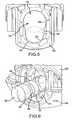
- Fig. 6illustrates a male bayonet connector 160 entering the aperture of the housing 102.
- the male bayonet connector 160may include a proximal portion 162 shaped as a conical frustum that may be used for coupling with plastic tubing.
- the distal portion 164 of the connectormay be generally cylindrical with a substantially flat surface that may serve as a sealing surface when the male bayonet is fully inserted into the female receiving connector 100.
- the distal portion 164 of the male connectormay have other shapes.
- the distal portion 164may have a frustum shape.
- a foremost edge 166 of the male connector 160may have a chamfered edge.
- the foremost edge 166may have a curved shape.
- the male connectoralso has an annular channel 168 located between the proximal and distal ends 162, 164.
- the annular channel 168may have flat or beveled edges that may be used to engage the locking plate 120.
- edgesmay be beveled to form a 45-degree angle with respect to the axes of the lumens defined by the male connector.
- the beveled edgesmay be perpendicular to the axes, rounded, or alternatively may define any angle between 0 and 90 degrees.
- a proximal surface 170 of the first area 150may have a shape corresponding to the foremost edge 166 of the male bayonet connector 160.
- the proximal surface 170may be chamfered or curved.
- the shape of the foremost edge 166 of the male bayonet connector 160, the proximal surface 170 of the first area 150, and/or the profile lead-in 128may aid in the movement of the locking plate 120 relative to the male bayonet connector 160.
- the male bayonet connector 160As the male bayonet connector 160 enters into the housing 102, it contacts the proximal surfaces of the aperture 142. As pressure is applied to insert the male bayonet connector 160 through the aperture 142, as indicated by the arrow 169 ( Figs. 6 , 7, and 8 ), the locking plate 120 is forced downward, as indicated by arrow 171 ( Figs. 7 and 8 ). In particular, because of the ramped profile lead-in 128, as pressure is applied to the locking plate 120 by pushing the male bayonet connector 160 into the aperture, the locking plate 120 is forced downward. The locking plate 120 continues downward until the male bayonet connector 160 is able to pass through the second aperture 158 ( Fig. 8 ).
- the male bayonet connector 160passes through the second aperture 158 until the channel of the male bayonet connector 160 is aligned with the profile lead-in 128.
- the locking plate 120is pushed back upward by legs 130 and the profile lead-in 128 engages the channel 168 to secure the male bayonet connector 160 within the female receiving connector 100 (see Fig. 9 ).
- the distal surface of the profile lead-in 128may be shaped to hold the male bayonet connector 160 in place once installed.
- the distal surface of the profile lead-inmay be flat.
- the distal surfacemay be chamfered.
- the chamfered surfacemay facilitate the locking plate 120 engaging the channel 168 of the male bayonet connector.
- the proximal surface and the distal surfacemay be chamfered.
- one of the distal or proximal surfaces of the profile lead-in 128is chamfered and the other surface is flat.
- the shape of the surfaces of the channel 168may correspond with the surfaces of the profile lead-in 128.
- a distal surface of the channel 168may be chamfered and the distal surface of the profile lead-in 128 may be chamfered.
- both the distal and proximal surfaces of the channel 168may be chamfered.
- both the proximal and distal surfaces of the channel 168may be flat.
- one of the proximal or distal surfacesmay be chamfered and the other surface flat.
- a shape of one or both surfaces of the channel of the male bayonet connector 160correspond in shape with the corresponding the surface of the profile lead-in 128.
- the distal surface of the profile lead-in 128is flat, the distal surface of the channel 168 is correspondingly flat. Additionally, the thickness of the profile lead-in 128 and the width of the channel of the male bayonet connector 160 are approximately the same.
- a distal portion of the male bayonet connector 160may be in contact with the sealing member 122 to form a seal between the sealing member 122 and the surface of distal portion 164 of the male bayonet connector 160.
- the button 108may be pressed downward to release the male bayonet connector 160 from the female receiving connector 100. Specifically, as the button 108 is pressed downward, the locking plate 120 moves downward until the male bayonet 160 may clear the profile lead-ins 128 and may pass through the second area 156.
- the female receiving connector 100may be implemented in multi-lumen configurations.
- the female receiving connector 100may include two, three, or more lumens.
- a locking plateis provided for each lumen.
- one or more locking platesmay be coupled together.
- one or more locking platesmay be integrally formed with the button 108.
- one or more locking platesmay be independently formed and subsequently coupled to the button 108.
- a shape of one or more locking platesmay include one or more different features from other locking plates.
- a first locking plate associated with a first lumenmay have a chamfered proximal surface, while a second locking plate associated with a second lumen may have a curved proximal surface.
- the distal surface of the first locking platemay have a chamfered surface, while a distal surface of a second locking plate may have a flat surface.
- Fig. 10illustrates a dual lumen female receiving connector 200 in accordance with an exemplary embodiment.
- the dual female receiving connector 200may be designed for connection between tubing from a blood pressure monitor and a male connector which is attached to tubing from a blood pressure cuff that may be fastened about a patient's arm.
- the dual lumen female receiving connector 200allows for two air pathways within the connector.
- the dual lumen female receiving connector 200includes a housing 202 that may include upper and lower portions 204, 206 and a button 208.
- Fig. 11illustrates the button 208 with a locking plate 210 and legs 212.
- the legs 212serve as spring members to hold the button 208 in a raised position within the housing 202. Additionally, the legs 212 provide a holding force to secure the male connector 230 in the female receiving connector when the two are coupled together. That is, the legs 212 hold the locking plate 210 in position while it engages the male connector 230.
- the locking plate 210includes two apertures 220, one for each lumen of the dual lumen female receiving connector 200.
- the apertures 220may be identical. That is, the apertures 220 may have the same or similar size and shape. In other embodiments, however, the apertures 220 may have different sizes and shapes. Additionally, in some embodiments, the lumens may be used to transport the same fluid, while in other embodiments, one lumen may transport a different fluid from the other.
- the apertures 220 of the locking plate 210are configured to facilitate the insertion of the male bayonet connectors 230 into the female receiving connector 200 while preventing their removal there from.
- the apertures 220include curved profile lead-ins 240.
- the profile lead-ins 240constitute a lower edge 242 of the apertures 220.
- the profile lead-ins 240are shown in Figs. 11 and 12 and generally may have regions which provide curved contours to facilitate insertion or securing of the male bayonet connector 230 within the female receiving connector 200.
- a center region 250may include curved portion 252 that extends from a proximal edge of the locking plate 210 toward a substantially flat surface 254 on the interior of the apertures 220.
- the substantially flat surface 254has a contour defined by a radius of a circle 256 ( Fig. 12 ) that corresponds to the radius of the outer surface of the male bayonet connector 230.
- the radius of the contourmay be larger or smaller as long as it can accept and interface with the channel of the male bayonet connector 230.
- the substantially flat surface 254extends to left and right regions 260, 262. In the left and right regions 260, 262, the substantially flat surface 254 tapers toward a distal edge 264 of the locking plate 210.
- the angle of the lead-in 240is 45 deg., leading into a .020" radius to generally flat locking surface 254. As seen in Fig.
- the locking surface 254may be formed with a slight (e.g., .097") radius.
- the locking edge 254transitions to a bulbous, radiused edge in left and right regions 260, 262 toward the edges of the aperture 220.
- the shape of the left and right regions 260, 262is the primary factor to the ease of insertion of the male connector 230 as it rides over the bulbous surface, forcing the button to the "down" position.
- the curved portions 252also extend into the left and right regions 260, 262.
- the curved portionmay have a convex contour.
- the convex contourmay extend from the proximal edge 266 of the locking plate 210 towards its distal edge 264. Because of the tapering of the substantially flat surface 254 in the left region 260, the convex contour expands as it progresses from the center region 250 through the left region 260.
- An apex of the curved portionis extended into the edge 272 of the aperture, forming a curved ledge.
- the right region 262is generally a mirror image of the left region 260 and as such has similar features.
- the profile of the substantially flat surface 254may be seen.
- the substantially flat surface 254 of the center region 250may be defined by the circumference of a circle 256 that correlates with the circumference of the channel of the male bayonet connector 230.
- the substantially flat surface 254 of the left and right regions 260, 262, however,may have different profiles in different embodiments.
- the profile of the substantially flat surface 254may be defined by a substantially straight line in the left and right regions 260, 262.
- the profilemay have a decreasing slope as it approaches the edge 272, defining a convex profile.
- the profilemay be slightly concave, but less so than the profile of the center region.
- the profile lead-ins 240provide the initial contact surfaces for the male bayonet connector 230 during insertion.
- Fig. 13illustrates the male bayonet connector entering the female receiving connectors 200.
- the top housing memberis removed to show detail with in the housing.
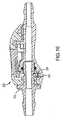
- Fig. 14is a cross sectional view showing the male bayonet connector 230 contacting the profile lead-in 240 of the center region 250. The contact of the profile lead-in 240 by the male bayonet connector 230 forces the locking plate 210 downward until the sealing surface of the male bayonet connector 230 is able to pass through the aperture 220, as shown in Fig. 15 .
- the male bayonet connector 230may further be inserted into the aperture 220 until the channel of the male bayonet connector 230 and the substantially flat surface 254 of the center region 250 engage ( Fig. 16 ) to secure the male connector 230 within the female connector 200.
- a sealing membersuch as a rubber O-ring, may contact a sealing surface of the male bayonet connector 230 to seal the lumen.
- the substantially flat surface 254may perpendicularly adjoin a distal surface 280 of the profile lead-in 240 that is flat. That is, in one embodiment, the distal surface of the profile lead-in 240 may be flat. In some embodiments, the distal surface of the profile lead-in 240 and a distal surface of the locking plate 210 may be the same surface. In other embodiments, they may constitute different surfaces. A corresponding engagement surface of the channel may also be flat to help secure the male bayonet connector 230 within the female receiving connector 200. In other embodiments, the distal surface 280 of the locking plate 210 may take other forms. For example, in one embodiment, the distal surface 280 may be chamfered.
- Fig. 17is a partial cross sectional view from a distal perspective of the button 208 and the male bayonet connector 230 with the male bayonet connector secured within the locking plate 210.
- the male bayonet connector 230is secured within the lower portion of the aperture 220 while the upper portion of the aperture is vacant.
- the profile lead-in 240, the substantially flat surface 254, and the distal surface 280 of the locking plate 210may each be in contact with the channel of the male bayonet connector 230 to secure the male bayonet connector.
- the profile lead-ins 240may take other forms.
- Figs. 18-20illustrate alternative embodiments of the exemplary profile lead-ins.
- Fig. 18illustrates embodiment having the same general characteristics as the embodiment shown in Figs. 11 and 12 , but with profile lead-ins 282 in left and right regions extending further up the edges 272 of the apertures 220.
- Fig. 18has smaller "bulbous" radii in case the male shafts are molded on the large end of the tolerance range. The smaller radii will enable the male shafts to more easily glide on and force down the button latch.
- the profile lead-ins 282 in the left and right regionsmay have a more gradual contour when compared to the embodiments shown in Figs. 11 and 12 .
- Fig. 19illustrates an embodiment having a profile lead-in 290 with a continuous profile with very little side loft on a narrow and short flat engaging surface 292. That is, the entirety of the flat engaging surface 292 may have a profile defined by the circumference of a circle that corresponds to the circumference of the channel of the male bayonet connector 230. The substantially flat surface 292 gradually tapers from the proximal edge 294 to the distal edge 296 of the locking plate 210 as it approaches the edges 272.
- Fig. 20illustrates an embodiment similar to the embodiments illustrated in Figs. 11, 12 , and 18 , having profile lead-ins 298 with higher edge loft 300 than the form of Figs. 18 and 19 , but with lower loft than in the embodiment of Fig. 3 .
- Fig. 20has larger bulbous radii in case the male shafts are molded on the small side of the tolerance range. The larger bulbous radii will enable the interference between the lead-in 298 and the male shafts to occur at about the same male insertion depth compared to shafts molded to the nominal dimensions.
- the flat surface 302is wider than in the embodiment of Fib. 19 and extends into the edge 272 to form a ledge across the bottom of the aperture. In Fig. 20 , the edges 272 are thick, flat, and straight.
- the profile lead-inis designed to maintain a relatively low insertion force of the male connector while also maintaining a robust distal edge of the locking plate so that it locks/holds the male connector to the female receiving connector when fully inserted.
- Prototypeshave been built of the various embodiments described above and experiments performed to confirm the male connector insertion force that actuates the locking plate downward to allow for insertion of the male connector is relatively low. Additionally, experiments were performed to confirm the axial pull force that results in the male connector decoupling from the female receiving connector when fully inserted and locked is relatively high.
- a profile lead-inmay be implemented with a curved portion to form a profile, profile lead in.
- lumenrefers not only to its definition, but also refers to an opening, aperture, or other passageway.
- the fluid referred to hereincan be gaseous, liquid, or other state of material that is flowable through a tube (i.e., granular).
- the connector structuresmay be sealed or unsealed.
- the connection between the male dual bayonet connector and female receiving connectors and their respective tube sectionscan be by means other than a barbed fitting, for example, but not limited to, threaded, press-fit without a barb, John Guest fitting, ferrule, and panel mount.
Landscapes
- Health & Medical Sciences (AREA)
- Engineering & Computer Science (AREA)
- Heart & Thoracic Surgery (AREA)
- General Engineering & Computer Science (AREA)
- Hematology (AREA)
- Pulmonology (AREA)
- Anesthesiology (AREA)
- Biomedical Technology (AREA)
- Life Sciences & Earth Sciences (AREA)
- Animal Behavior & Ethology (AREA)
- General Health & Medical Sciences (AREA)
- Public Health (AREA)
- Veterinary Medicine (AREA)
- Mechanical Engineering (AREA)
- Quick-Acting Or Multi-Walled Pipe Joints (AREA)
- Infusion, Injection, And Reservoir Apparatuses (AREA)
Description
- This application claims priority to
U.S. provisional application no. 61/361,306 filed 2 July 2010 U.S. provisional application no. 61/289,990 filed 23 December 2009 - The present disclosure relates generally to the field of both gaseous and liquid fluid transport and more specifically, to a connector for creating a releasable fluid seal connection between one or more sections of tubing and a female latch.
- Tubing sections are often joined together to provide for gas and/or liquid fluid flow from one component to another. Thus, it is often desirable to connect and disconnect tubing sections from one another. For example, when a patient's blood pressure is taken with an automatic blood pressure monitor, tubing from the blood pressure cuff (which is generally wrapped around the patient's arm) is connected to the tubing that is connected to the blood pressure monitor. To disconnect the cuff from the blood pressure monitor, it is desirable to merely detach the tubing section connected to the cuff from the tubing connected to the blood pressure monitor. Similarly, when providing intravenous fluids, it is often required to replace an empty fluid bag with a full fluid bag without removing the intravenous needle or stent from the patient. In order to switch between the first fluid bag and the second fluid bag, it is desirable to merely detach a tubing section connected with the fluid bag to the tubing section connected with the needle or stent placed intravenously in the patient, which can then be easily connected with a tubing section connected with the new fluid bag.
- Existing tubing connectors are prone to leakage and unwanted disconnection when the patient is still receiving treatment via the connected tubes due to side loads caused by the weight of the connected tubes and components, as well as accidental pulling of the tubes by the patient or medical personnel.
- Furthermore, certain medical devices require the use of multiple tubes for supplying fluid between the patient and the device. For example, certain models of blood pressure monitors, such as the Dinamap Procare series, manufactured by General Electric, employ dual tubes for connecting the blood pressure cuff to the monitor. As such, a connector including multiple air passages for directing airflow between the tube segments is desirable, so as to avoid having to individually connect and disconnect multiple connectors when hooking or unhooking a patient to the monitor.
- From the foregoing, it can be appreciated that a need exists for an improved bayonet connector that may connect one or more sections of tubing to create a gas and/or liquid fluid seal that cooperates with a female receiving connector to provide a more resilient connection and maintain a fluid-tight seal when the male bayonet connector is placed under axial tension or side load forces.
- The information included in this Background section of the specification, including any references cited herein and any description or discussion thereof, is included for technical reference purposes only and is not to be regarded subject matter by which the scope of the invention is to be bound.
- Improved female tube connectors are disclosed herein that reduce insertion force requirements for coupling with male connectors. Additionally, the female tube connectors increase the amount of force required to extract male connectors once they are secured within the female tube connectors to prevent accidental uncoupling of the male connector from the female connector.
- Generally, a locking member that is coupled to a button of the female tube connectors may take various forms to help ensure relatively low insertion force and relatively high extraction force for coupling and uncoupling male connectors. Specifically, the locking member may include a profile lead-in to help reduce the amount of force to insert a male connector into the female connector while increasing the amount of force to extract the male connector once coupled to the female connector.
- In one embodiment of the invention as defined in the claims, a female receiving connector for connecting sections of tubing is provided. The female receiving connector includes a housing having a top housing portion and a bottom housing portion coupled to the top housing portion. The female receiving connector also includes a button moveably coupled within the housing. A locking plate is integral with or coupled to the button and configured to move with the button. The locking plate has a profile lead-in having an interfacing surface located at a proximal side of the profile lead-in for interfacing with a male connector. The interfacing surface extends along at least a portion of a circumferential edge of an aperture formed within the locking plate and is tapered along the portion of the circumferential edge. Additionally, the profile lead-in includes a locking surface located at a distal side of the lofted lead-in for securing the male connector within the housing of the female receiving connector. A substantially flat surface is located between the interfacing surface and the locking surface.
- A more extensive presentation of features, details, utilities, and advantages of the present invention is provided in the following written description of various embodiments of the invention, illustrated in the accompanying drawings, and defined in the appended claims.
FIG. 1 illustrates a female receiving connector in accordance with an exemplary embodiment.Fig. 2 illustrates the female receiving connector ofFig. 1 without a top housing portion.Fig. 3 illustrates a button of the female receiving connector ofFig. 1 having a locking plate with profile lead-ins.Fig. 4 is an enlarged view of the locking plate with profile lead-ins ofFig. 3 .Fig. 5 is a front elevation view of the locking plate ofFig. 3 illustrating an aperture of the locking plate.Fig. 6 illustrates a male bayonet connector entering a housing of the female receiving connector ofFig. 2 .Fig. 7 illustrates the male bayonet connector ofFig. 6 interfacing with the locking plate to force the locking plate downward.Fig. 8 illustrates the male bayonet connector ofFig. 6 pushing the locking plate fully downward and passing through the aperture ofFig. 5 .Fig. 9 illustrates the male bayonet connector ofFig. 6 secured by the locking plate.Fig. 10 illustrates a dual lumen female receiving connector in accordance with an alternative embodiment.Fig. 11 is an isometric view of a button of the dual lumen female receiving connector ofFig. 10 with a locking plate having profile lead-ins.Fig. 12 is a front elevation view of the button ofFig. 11 illustrating an aperture of the locking plate.Figs. 13 illustrates a dual male bayonet connector entering the dual lumen female receiving connector ofFig. 10 with a top housing portion of the housing removed.Fig. 14 is a cross sectional view of the dual lumen female connector ofFig. 10 with the dual lumen male connector contacting a profile lead-in.Fig. 15 is a cross-sectional view of the dual lumen male bayonet connector passing through the aperture ofFig. 12 .Fig. 16 is a cross-sectional view of the dual lumen male bayonet connector secured by a locking plate of the female receiving connector ofFig. 10 .Fig. 17 illustrates a cross-sectional view from a distal perspective of the male bayonet connector secured by a locking plate of the female receiving connector ofFig. 10 .Figs. 18-20 illustrate multiple embodiments of latch buttons having example alternative profile lead-ins for use in the female receiving connector ofFig. 10 .- Embodiments of female receiving connectors in conjunction with male bayonet connectors, may be used to releasably connect sections of tubing. In one embodiment, the female receiving connector includes a latch plate with a profile lead-in that extends upward along the lateral sides of the aperture in the latch plate. The profile lead-in provides extended latching surfaces for the latch plate to secure a male bayonet connector. When the male bayonet connector is inserted into the female receiving connector, a distal end of the male bayonet connector interfaces the profile lead-in, biases the latch plate downward, and lowers a receiving aperture through which the male bayonet connector may pass. The male bayonet connector includes an annular channel that is engaged by the profile lead-in upon sufficient insertion of the male bayonet connector into the female receiving connector.
- The orientations "proximal" and "distal" as used herein have been arbitrarily chosen, and are not meant to limit the present disclosure, but will follow the convention just described with reference to the ends of the
female receiving connector 206 and maledual bayonet connector 102. - In an alternative embodiment, a female receiving connector may include a locking plate having a profile lead-in as a curved bottom surface of the aperture in the locking plate. When the male bayonet connector is inserted into the female connector, the male bayonet connector interfaces the profile lead-in, biasing the locking plate downward and lowering a receiving aperture through which the male bayonet connector may pass. The male bayonet connector's annular channels are engaged by a distal surface of the profile lead-in upon sufficient insertion of the male bayonet connector into the female receiving connector.
- In some embodiments, the profile lead-in lead-in may be implemented in multiple parallel lumen configurations. For example, in some embodiments, the profile lead-in may be implemented in a dual lumen configuration (e.g., the female connector having two parallel lumens through which fluid may pass and into which male connectors may be inserted). Additionally, in some embodiments, the profile lead-in may have one or more chamfered surfaces that engage the annular channels of the male bayonet connectors. In some embodiments, a distal edge of the locking plate may be flat to interface with the flat surface of the annular channel.
- An exemplary
female receiving connector 100 is illustrated inFig. 1 . Thefemale receiving connector 100 includes ahousing 102 having atop portion 104 and abottom portion 106. Abutton 108 is movably coupled to thehousing 102 and externally accessible to allow for disengagement of a male connector from a locking member, as discussed in greater detail below. Thehousing 102 andbutton 108 may be made of a suitable material via a suitable process. In some embodiments, thehousing 102 andbutton 108 may be made of a plastic material via a molding process, such as an injection molding process. In other embodiments, one or more parts of thefemale receiving connector 100 may be made via a milling process, such as a computer numerical control (CNC) milling process. Thetop portion 104 and thebottom portion 106 may be secured together in a suitable manner, such as implementing snap fits that are integrally formed with the top and bottom portions. In other embodiments, the top and bottom portions may be secured together in other manners, for example, via adhesive or ultrasonic welding. - The
housing 102 includes receivingaperture 110 through which a male bayonet connector may be inserted. Theaperture 110 is located at a proximal end of thefemale receiving connector 100 and may be defined by the upper and/orlower portions housing 102. Theaperture 110 constitutes a proximal end oflumen 112 extending through thefemale receiving connector 100. Thelumen 112 continues through abarbed tube connector 114 located at the distal end of thefemale receiving connector 100. Thebarbed tube connector 114 is configured for attachment of plastic tubing. Fig. 2 shows thefemale receiving connector 100 with thetop portion 104 of thehousing 102 removed to show additional details inside thehousing 102. As illustrated, thebutton 108 includes alocking plate 120. In some embodiments, the lockingplate 120 may be integrally formed with thebutton 108, while in other embodiments, the lockingplate 120 and thebutton 108 may be formed separately and later coupled together. Further, in other embodiments structures other than a button, e.g., a slide, a switch, a lever, or other structures, may be used to operate thelocking plate 120. The lockingplate 120 extends downward from thebutton 108 and is configured to move in conjunction with thebutton 108. A sealingmember 122, such as a rubber O-ring may be located directly behind the lockingmember 120. The sealingmember 122 is secured in place behind the lockingplate 120 by a sealingmember retainer 124. The sealingmember retainer 124 may be a suitable holding structure into which the sealingmember 122 is inserted and held. In some embodiments, the sealingmember retainer 124 may be integrally formed with thebottom portion 106 of thehousing 102. In other embodiments, the sealingmember retainer 124 may be formed separately from thebottom portion 106 of thehousing 102 and subsequently coupled to the bottom portion. The sealingmember 122 may be secured within a channel located behind the sealingmember retainer 124.- The locking
plate 120 includes a profile lead-in 128.Fig. 3 illustrates thebutton 108 independent from thebottom portion 106 of thehousing 102, so that the profile lead-in 128 may be more easily seen and described. Generally, the profile lead-in 128 extends upward alongedges 140 of anaperture 142 of thelocking plate 120. The profile lead-in 128 functions as an improved locking structure. That is, because it extends upward along the edges of theaperture 142, the profile lead-in 128 provides additional structure for locking in a male bayonet connector. - As illustrated, the
button 108 includes the lockingmember 120 as an integrated part. Additionally, thebutton 108 includescurved legs 130 which may interface with thebottom portion 106 of thehousing 102 and function as springs to hold thebutton 108 up within thehousing 102. That is, thelegs 130 have a normally extended position to hold up thebutton 108. When the button is pressed, thelegs 130 may bend and when pressure is released, the legs may return to full extension, thus providing a spring function. In other embodiments, other kinds of mechanical action than springs may be employed raise the button back up to its resting place when the force is removed. Fig. 4 is an enlarged image of theaperture 142 of thebutton 108 shown inFig. 3 . As may be seen, the profile lead-in 128 has a ramped shape. Specifically, aproximal surface 132 of the profile lead-in 128 tapers toward thedistal edge 134 of thelocking plate 120 as the profile lead-in 128 progress upward along theedge 140 of theaperture 142. The ramp is provided so that as a male bayonet connector is pressed against the profile lead-in 128, for example, during insertion of the male bayonet connector into thefemale receiving connector 100, the lockingplate 120 is forced downward. The range of angles for the pitch of the ramp depends on the distance the groove is from the front of the male connector tip or the distance the male connector has to travel in order for the profile lead in to lock into the groove on the male connector. In some embodiments, the ramp may be pitched at between 44° and 46°.Fig. 5 shows theaperture 142 as including two generally circular areas with overlapping circumferences. A first area 150 is defined by afirst circumference 152 in a lower portion of theaperture 142. The profile lead-in 128 and a base lead-in 154 define thecircumference 152 of the first area 150. Asecond area 156 is defined by asecond circumference 158. A portion of thesecond circumference 158 may be formed by a top edge of the profile lead-in 128. As such, the top edge of the profile lead-in 128 may have a curved shape.- The
second circumference 158 and thefirst circumference 152 overlap. Thesecond circumference 158 is larger than thefirst circumference 152 and, therefore, thesecond area 156 is larger than the first area 150. Thesecond area 158 is large enough to allow for the passage of a male bayonet therethrough, while thefirst area 152 functions as a locking aperture to engage and hold the male bayonet connector. Fig. 6 illustrates amale bayonet connector 160 entering the aperture of thehousing 102. In some embodiments, themale bayonet connector 160 may include aproximal portion 162 shaped as a conical frustum that may be used for coupling with plastic tubing. Thedistal portion 164 of the connector may be generally cylindrical with a substantially flat surface that may serve as a sealing surface when the male bayonet is fully inserted into thefemale receiving connector 100. In other embodiments thedistal portion 164 of the male connector may have other shapes. For example, in one embodiment, thedistal portion 164 may have a frustum shape. Additionally, in some embodiments, aforemost edge 166 of themale connector 160 may have a chamfered edge. In some embodiments, theforemost edge 166 may have a curved shape.- The male connector also has an
annular channel 168 located between the proximal anddistal ends annular channel 168 may have flat or beveled edges that may be used to engage thelocking plate 120. For example, in some embodiments, edges may be beveled to form a 45-degree angle with respect to the axes of the lumens defined by the male connector. In other embodiments, the beveled edges may be perpendicular to the axes, rounded, or alternatively may define any angle between 0 and 90 degrees. - In some embodiments, a
proximal surface 170 of the first area 150 may have a shape corresponding to theforemost edge 166 of themale bayonet connector 160. For example, theproximal surface 170 may be chamfered or curved. The shape of theforemost edge 166 of themale bayonet connector 160, theproximal surface 170 of the first area 150, and/or the profile lead-in 128 may aid in the movement of thelocking plate 120 relative to themale bayonet connector 160. - As the
male bayonet connector 160 enters into thehousing 102, it contacts the proximal surfaces of theaperture 142. As pressure is applied to insert themale bayonet connector 160 through theaperture 142, as indicated by the arrow 169 (Figs. 6 ,7, and 8 ), the lockingplate 120 is forced downward, as indicated by arrow 171 (Figs. 7 and 8 ). In particular, because of the ramped profile lead-in 128, as pressure is applied to thelocking plate 120 by pushing themale bayonet connector 160 into the aperture, the lockingplate 120 is forced downward. The lockingplate 120 continues downward until themale bayonet connector 160 is able to pass through the second aperture 158 (Fig. 8 ). Themale bayonet connector 160 passes through thesecond aperture 158 until the channel of themale bayonet connector 160 is aligned with the profile lead-in 128. When thechannel 168 is aligned with the profile lead-in 128, the lockingplate 120 is pushed back upward bylegs 130 and the profile lead-in 128 engages thechannel 168 to secure themale bayonet connector 160 within the female receiving connector 100 (seeFig. 9 ). - The distal surface of the profile lead-in 128 may be shaped to hold the
male bayonet connector 160 in place once installed. For example, in some embodiments, the distal surface of the profile lead-in may be flat. In other embodiments, the distal surface may be chamfered. The chamfered surface may facilitate thelocking plate 120 engaging thechannel 168 of the male bayonet connector. In some embodiments, the proximal surface and the distal surface may be chamfered. In another embodiment, one of the distal or proximal surfaces of the profile lead-in 128 is chamfered and the other surface is flat. - In some embodiments, the shape of the surfaces of the
channel 168 may correspond with the surfaces of the profile lead-in 128. For example, in one embodiment, a distal surface of thechannel 168 may be chamfered and the distal surface of the profile lead-in 128 may be chamfered. In some embodiments both the distal and proximal surfaces of thechannel 168 may be chamfered. In some embodiments, both the proximal and distal surfaces of thechannel 168 may be flat. In other embodiments, one of the proximal or distal surfaces may be chamfered and the other surface flat. In each instance, a shape of one or both surfaces of the channel of themale bayonet connector 160 correspond in shape with the corresponding the surface of the profile lead-in 128. That is, if the distal surface of the profile lead-in 128 is flat, the distal surface of thechannel 168 is correspondingly flat. Additionally, the thickness of the profile lead-in 128 and the width of the channel of themale bayonet connector 160 are approximately the same. - When the
male bayonet connector 160 is locked into place by the lockingplate 120, a distal portion of themale bayonet connector 160 may be in contact with the sealingmember 122 to form a seal between the sealingmember 122 and the surface ofdistal portion 164 of themale bayonet connector 160. - The
button 108 may be pressed downward to release themale bayonet connector 160 from thefemale receiving connector 100. Specifically, as thebutton 108 is pressed downward, the lockingplate 120 moves downward until themale bayonet 160 may clear the profile lead-ins 128 and may pass through thesecond area 156. - As mentioned above, the
female receiving connector 100 may be implemented in multi-lumen configurations. For example, thefemale receiving connector 100 may include two, three, or more lumens. For each lumen, a locking plate is provided. In some embodiments, one or more locking plates may be coupled together. Additionally, in some embodiments, one or more locking plates may be integrally formed with thebutton 108. In some embodiments, one or more locking plates may be independently formed and subsequently coupled to thebutton 108. Additionally, in some embodiments, a shape of one or more locking plates may include one or more different features from other locking plates. For example, in one embodiment, a first locking plate associated with a first lumen may have a chamfered proximal surface, while a second locking plate associated with a second lumen may have a curved proximal surface. In another example, the distal surface of the first locking plate may have a chamfered surface, while a distal surface of a second locking plate may have a flat surface. Fig. 10 illustrates a dual lumenfemale receiving connector 200 in accordance with an exemplary embodiment. In one embodiment, the dualfemale receiving connector 200 may be designed for connection between tubing from a blood pressure monitor and a male connector which is attached to tubing from a blood pressure cuff that may be fastened about a patient's arm. The dual lumenfemale receiving connector 200 allows for two air pathways within the connector. As with the single lumen discussed above, the dual lumenfemale receiving connector 200 includes ahousing 202 that may include upper andlower portions button 208.Fig. 11 illustrates thebutton 208 with alocking plate 210 andlegs 212. Thelegs 212 serve as spring members to hold thebutton 208 in a raised position within thehousing 202. Additionally, thelegs 212 provide a holding force to secure themale connector 230 in the female receiving connector when the two are coupled together. That is, thelegs 212 hold thelocking plate 210 in position while it engages themale connector 230.- The locking
plate 210 includes twoapertures 220, one for each lumen of the dual lumenfemale receiving connector 200. In some embodiments, theapertures 220 may be identical. That is, theapertures 220 may have the same or similar size and shape. In other embodiments, however, theapertures 220 may have different sizes and shapes. Additionally, in some embodiments, the lumens may be used to transport the same fluid, while in other embodiments, one lumen may transport a different fluid from the other. - The
apertures 220 of thelocking plate 210 are configured to facilitate the insertion of themale bayonet connectors 230 into thefemale receiving connector 200 while preventing their removal there from. As such, theapertures 220 include curved profile lead-ins 240. The profile lead-ins 240 constitute a lower edge 242 of theapertures 220. The profile lead-ins 240 are shown inFigs. 11 and 12 and generally may have regions which provide curved contours to facilitate insertion or securing of themale bayonet connector 230 within thefemale receiving connector 200. For example, in one embodiment, acenter region 250 may includecurved portion 252 that extends from a proximal edge of thelocking plate 210 toward a substantiallyflat surface 254 on the interior of theapertures 220. The substantiallyflat surface 254 has a contour defined by a radius of a circle 256 (Fig. 12 ) that corresponds to the radius of the outer surface of themale bayonet connector 230. The radius of the contour may be larger or smaller as long as it can accept and interface with the channel of themale bayonet connector 230. The substantiallyflat surface 254 extends to left andright regions right regions flat surface 254 tapers toward adistal edge 264 of thelocking plate 210. In one exemplary embodiment, the angle of the lead-in 240 is 45 deg., leading into a .020" radius to generallyflat locking surface 254. As seen inFig. 11 , the lockingsurface 254 may be formed with a slight (e.g., .097") radius. The lockingedge 254 transitions to a bulbous, radiused edge in left andright regions aperture 220. The shape of the left andright regions male connector 230 as it rides over the bulbous surface, forcing the button to the "down" position. - The
curved portions 252 also extend into the left andright regions left region 260, for example, the curved portion may have a convex contour. The convex contour may extend from theproximal edge 266 of thelocking plate 210 towards itsdistal edge 264. Because of the tapering of the substantiallyflat surface 254 in theleft region 260, the convex contour expands as it progresses from thecenter region 250 through theleft region 260. An apex of the curved portion is extended into theedge 272 of the aperture, forming a curved ledge. Theright region 262 is generally a mirror image of theleft region 260 and as such has similar features. - Referring to
Fig. 12 , the profile of the substantiallyflat surface 254 may be seen. As discussed above, the substantiallyflat surface 254 of thecenter region 250 may be defined by the circumference of acircle 256 that correlates with the circumference of the channel of themale bayonet connector 230. The substantiallyflat surface 254 of the left andright regions flat surface 254 may be defined by a substantially straight line in the left andright regions edge 272, defining a convex profile. In other embodiments, the profile may be slightly concave, but less so than the profile of the center region. - The profile lead-
ins 240 provide the initial contact surfaces for themale bayonet connector 230 during insertion.Fig. 13 illustrates the male bayonet connector entering thefemale receiving connectors 200. InFig. 13 , the top housing member is removed to show detail with in the housing.Fig. 14 is a cross sectional view showing themale bayonet connector 230 contacting the profile lead-in 240 of thecenter region 250. The contact of the profile lead-in 240 by themale bayonet connector 230 forces the lockingplate 210 downward until the sealing surface of themale bayonet connector 230 is able to pass through theaperture 220, as shown inFig. 15 . Themale bayonet connector 230 may further be inserted into theaperture 220 until the channel of themale bayonet connector 230 and the substantiallyflat surface 254 of thecenter region 250 engage (Fig. 16 ) to secure themale connector 230 within thefemale connector 200. When themale bayonet connector 230 is secured within thefemale receiving connector 200, a sealing member, such as a rubber O-ring, may contact a sealing surface of themale bayonet connector 230 to seal the lumen. - As illustrated in
FIG. 17 , the substantiallyflat surface 254 may perpendicularly adjoin adistal surface 280 of the profile lead-in 240 that is flat. That is, in one embodiment, the distal surface of the profile lead-in 240 may be flat. In some embodiments, the distal surface of the profile lead-in 240 and a distal surface of thelocking plate 210 may be the same surface. In other embodiments, they may constitute different surfaces. A corresponding engagement surface of the channel may also be flat to help secure themale bayonet connector 230 within thefemale receiving connector 200. In other embodiments, thedistal surface 280 of thelocking plate 210 may take other forms. For example, in one embodiment, thedistal surface 280 may be chamfered. Fig. 17 is a partial cross sectional view from a distal perspective of thebutton 208 and themale bayonet connector 230 with the male bayonet connector secured within the lockingplate 210. As can be seen, themale bayonet connector 230 is secured within the lower portion of theaperture 220 while the upper portion of the aperture is vacant. Additionally, the profile lead-in 240, the substantiallyflat surface 254, and thedistal surface 280 of thelocking plate 210 may each be in contact with the channel of themale bayonet connector 230 to secure the male bayonet connector.- It should be appreciated that, in other embodiments, the profile lead-
ins 240 may take other forms.Figs. 18-20 illustrate alternative embodiments of the exemplary profile lead-ins. In particular,Fig. 18 illustrates embodiment having the same general characteristics as the embodiment shown inFigs. 11 and 12 , but with profile lead-ins 282 in left and right regions extending further up theedges 272 of theapertures 220.Fig. 18 has smaller "bulbous" radii in case the male shafts are molded on the large end of the tolerance range. The smaller radii will enable the male shafts to more easily glide on and force down the button latch. Thus, the profile lead-ins 282 in the left and right regions may have a more gradual contour when compared to the embodiments shown inFigs. 11 and 12 . Fig. 19 illustrates an embodiment having a profile lead-in 290 with a continuous profile with very little side loft on a narrow and short flatengaging surface 292. That is, the entirety of the flatengaging surface 292 may have a profile defined by the circumference of a circle that corresponds to the circumference of the channel of themale bayonet connector 230. The substantiallyflat surface 292 gradually tapers from theproximal edge 294 to thedistal edge 296 of thelocking plate 210 as it approaches theedges 272.Fig. 20 illustrates an embodiment similar to the embodiments illustrated inFigs. 11, 12 , and18 , having profile lead-ins 298 withhigher edge loft 300 than the form ofFigs. 18 and19 , but with lower loft than in the embodiment ofFig. 3 .Fig. 20 has larger bulbous radii in case the male shafts are molded on the small side of the tolerance range. The larger bulbous radii will enable the interference between the lead-in 298 and the male shafts to occur at about the same male insertion depth compared to shafts molded to the nominal dimensions. Theflat surface 302 is wider than in the embodiment of Fib. 19 and extends into theedge 272 to form a ledge across the bottom of the aperture. InFig. 20 , theedges 272 are thick, flat, and straight.- The profile lead-in is designed to maintain a relatively low insertion force of the male connector while also maintaining a robust distal edge of the locking plate so that it locks/holds the male connector to the female receiving connector when fully inserted. Prototypes have been built of the various embodiments described above and experiments performed to confirm the male connector insertion force that actuates the locking plate downward to allow for insertion of the male connector is relatively low. Additionally, experiments were performed to confirm the axial pull force that results in the male connector decoupling from the female receiving connector when fully inserted and locked is relatively high.
- It will be apparent to those of ordinary skill in the art that variations and alternative embodiments may be made given the foregoing description. Such variations and alternative embodiments are accordingly considered within the scope of the present invention. For example, a profile lead-in may be implemented with a curved portion to form a profile, profile lead in.
- As used herein, lumen refers not only to its definition, but also refers to an opening, aperture, or other passageway. The fluid referred to herein can be gaseous, liquid, or other state of material that is flowable through a tube (i.e., granular). In addition, while generally described above as sealed when connected together, the connector structures may be sealed or unsealed. The connection between the male dual bayonet connector and female receiving connectors and their respective tube sections can be by means other than a barbed fitting, for example, but not limited to, threaded, press-fit without a barb, John Guest fitting, ferrule, and panel mount.
- All directional references (e.g., upper, lower, upward, downward, left, right, leftward, rightward, top, bottom, above, below, inner, outer, vertical, horizontal, clockwise, and counterclockwise) are only used for identification purposes to aid the reader's understanding of the example of the invention, and do not create limitations, particularly as to the position, orientation, or use of the invention unless specifically set forth in the claims. Joinder references (e.g., attached, coupled, connected, joined, and the like) are to be construed broadly and may include intermediate members between a connection of elements and relative movement between elements. As such, joinder references do not necessarily infer that two elements are directly connected and in fixed relation to each other.
- In methodologies directly or indirectly set forth herein, various steps and operations are described in one possible order of operation. Changes in detail or structure may be made without departing from the invention as defined in the appended claims.
Claims (14)
- A female receiving connector (100) for connecting sections of tubing comprising
a housing (102) further comprisinga top housing portion (104);a bottom housing portion (106) coupled to the top housing portion (104); anda button (108) moveably coupled within the housing (102): anda locking plate (120) coupled to the button (108) and configured to move with the button (108). the locking plate (120) defining an aperture (142) having a profile lead-in (128) further comprisingan interfacing surface (132) for interfacing with a male connector (160) inserted through the aperture (142), wherein the interfacing surface (132) extends along at least a portion of at least three sides of the aperture (142) of the locking plate (120) and the interfacing surface (132) is tapered along one or more of the at least three sides; a locking surface (140) located on a distal side of a bottom surface or lateral edges of the profile lead-in (128) for securing the male connector (160) within the housing (102) of the female receiving connector (100); anda substantially fiat surface (134).whereinthe interfacing surface (132) located at a proximal side of the profile lead-in (128), andthe substantially flat surface (134) located between the interfacing surface (132) and the locking surface (140) and extends to lateral edges of the aperture (142); andthe substantially flat surface (134) tapers in thickness distally as the substantially flat surface (134) approaches the lateral edges. - The female receiving connector (100) of claim 1, wherein the locking surface (140) is perpendicular to the substantially flat surface (134).
- The female receiving connector (100) of claim 1, wherein interfacing surface (132) comprises a chamfered surface.
- The female receiving connector (100) of claim 1, wherein
the aperture (142) of the locking plate (120) comprises two overlapping areas; and
a first area (150) is defined by a circumference (152) of a first circle that is smaller than a circumference (158) of a second circle that defines a second area (156); whereby
the female receiving connector (100) is configured to allow the male connector (160) to pass through the second area (156) and secure the male connector (160) within the first area (150). - The female receiving connector (100) of claim 1, wherein the button (108) and the locking plate (120) are integrally formed.
- The female receiving connector (100) of claim 1, wherein the interfacing surface (132) expands in thickness distally as the substantially flat surface (134) tapers.
- The female receiving connector (100) of claim 1, and a male connector wherein the substantially flat surface (134) has a substantially constant profile defined by a radius of a circle that corresponds to a radius of an outer surface of the male connector (160).
- The female receiving connector (100) of claim 1, wherein the button (108) is retained by the top housing portion (104).
- The female receiving connector (100) of claim 4, wherein the interfacing surface (132), the locking surface (140), and the substantially flat surface (134) are associated with the first area (150).
- The female receiving connector (100) of claim 1, wherein the interfacing surface (132) is curved.
- The female receiving connector (100) of claim 10, wherein an apex of the curved surface extends into the lateral edges of the aperture (142) forming a curved ledge.
- The female receiving connector (100) of claim 10, wherein the curved surface terminates at the lateral edges of the aperture (142).
- The female receiving connector (100) of claim 1, and a male connector wherein the substantially flat surface (134) has a substantially constant profile defined by a radius of a circle that corresponds to a radius of an outer surface of the male connector (160).
- The female receiving connector (100) of claim 1, wherein the locking surface (140) of the profile lead-in (128) is the same as a distal surface of the locking plate (120).
Applications Claiming Priority (3)
| Application Number | Priority Date | Filing Date | Title |
|---|---|---|---|
| US28999009P | 2009-12-23 | 2009-12-23 | |
| US36130610P | 2010-07-02 | 2010-07-02 | |
| PCT/US2010/061892WO2011079225A1 (en) | 2009-12-23 | 2010-12-22 | Fluid connector latches with profile lead-ins |
Publications (2)
| Publication Number | Publication Date |
|---|---|
| EP2516913A1 EP2516913A1 (en) | 2012-10-31 |
| EP2516913B1true EP2516913B1 (en) | 2014-09-17 |
Family
ID=43779742
Family Applications (1)
| Application Number | Title | Priority Date | Filing Date |
|---|---|---|---|
| EP10803695.5AActiveEP2516913B1 (en) | 2009-12-23 | 2010-12-22 | Fluid connector latches with profile lead-ins |
Country Status (8)
| Country | Link |
|---|---|
| US (1) | US9046205B2 (en) |
| EP (1) | EP2516913B1 (en) |
| JP (1) | JP5714028B2 (en) |
| KR (1) | KR101715636B1 (en) |
| CN (1) | CN102753877B (en) |
| MY (1) | MY159166A (en) |
| SG (1) | SG181936A1 (en) |
| WO (1) | WO2011079225A1 (en) |
Families Citing this family (67)
| Publication number | Priority date | Publication date | Assignee | Title |
|---|---|---|---|---|
| US20050082828A1 (en)* | 2003-09-12 | 2005-04-21 | Wicks Jeffrey C. | Releasable connection assembly for joining tubing sections |
| US7448653B2 (en) | 2005-06-10 | 2008-11-11 | Value Plastics, Inc. | Female connector for releasable coupling with a male connector defining a fluid conduit |
| US7806139B2 (en) | 2006-01-20 | 2010-10-05 | Value Plastics, Inc. | Fluid conduit coupling assembly having male and female couplers with integral valves |
| USD654573S1 (en) | 2007-11-19 | 2012-02-21 | Value Plastics, Inc. | Female quick connect fitting |
| US8235426B2 (en) | 2008-07-03 | 2012-08-07 | Nordson Corporation | Latch assembly for joining two conduits |
| USD655393S1 (en) | 2009-06-23 | 2012-03-06 | Value Plastics, Inc. | Multi-port valve |
| USD650478S1 (en) | 2009-12-23 | 2011-12-13 | Value Plastics, Inc. | Female dual lumen connector |
| USD783815S1 (en) | 2009-12-09 | 2017-04-11 | General Electric Company | Male dual lumen bayonet connector |
| US10711930B2 (en) | 2009-12-09 | 2020-07-14 | Nordson Corporation | Releasable connection assembly |
| US9388929B2 (en) | 2009-12-09 | 2016-07-12 | Nordson Corporation | Male bayonet connector |
| USD649240S1 (en) | 2009-12-09 | 2011-11-22 | Value Plastics, Inc. | Male dual lumen bayonet connector |
| MY159166A (en) | 2009-12-23 | 2016-12-30 | Nordson Corp | Fluid connector latches with profile lead-ins |
| JP5814257B2 (en) | 2009-12-23 | 2015-11-17 | ノードソン コーポレーションNordson Corporation | Button latch with integrally molded cantilever spring |
| USD652510S1 (en)* | 2011-02-11 | 2012-01-17 | Value Plastics, Inc. | Connector for fluid tubing |
| USD652511S1 (en)* | 2011-02-11 | 2012-01-17 | Value Plastics, Inc. | Female body of connector for fluid tubing |
| USD663022S1 (en)* | 2011-02-11 | 2012-07-03 | Nordson Corporation | Male body of connector for fluid tubing |
| USD698440S1 (en) | 2011-07-29 | 2014-01-28 | Nordson Corporation | Connector for fluid tubing |
| USD699841S1 (en) | 2011-07-29 | 2014-02-18 | Nordson Corporation | Female body of connector for fluid tubing |
| USD699840S1 (en) | 2011-07-29 | 2014-02-18 | Nordson Corporation | Male body of connector for fluid tubing |
| USD709612S1 (en) | 2011-12-23 | 2014-07-22 | Nordson Corporation | Female dual lumen connector |
| US8764068B2 (en)* | 2012-05-10 | 2014-07-01 | Moen Incorporated | Quick connect coupling with retention feature |
| US9616557B2 (en) | 2013-03-14 | 2017-04-11 | Black & Decker Inc. | Nosepiece and magazine for power screwdriver |
| WO2015023772A1 (en)* | 2013-08-15 | 2015-02-19 | Intuitive Surgical Operations, Inc. | Surgical instruments and methods of cleaning surgical instruments |
| USD730518S1 (en) | 2013-09-12 | 2015-05-26 | Nordson Corporation | Quick connect fluid connector |
| US9695966B2 (en) | 2013-09-13 | 2017-07-04 | Nordson Corporation | Quick connect fluid conduit connector having latch with integral spring arms for button release |
| FI3060276T3 (en)* | 2013-10-24 | 2023-06-07 | Infusion system for preventing mischanneling of multiple medicaments | |
| US20150151424A1 (en) | 2013-10-29 | 2015-06-04 | Black & Decker Inc. | Power tool with ergonomic handgrip |
| USD725981S1 (en) | 2013-10-29 | 2015-04-07 | Black & Decker Inc. | Screwdriver with nosepiece |
| USD743510S1 (en) | 2013-10-31 | 2015-11-17 | Nordson Corporation | High pressure fluid conduit connector components and connector assembly |
| US9534721B2 (en) | 2013-10-31 | 2017-01-03 | Nordson Corporation | High pressure fluid conduit connector components and connector assembly |
| CA2929476C (en)* | 2013-11-06 | 2019-01-22 | Becton Dickinson and Company Limited | System for closed transfer of fluids with a locking member |
| USD749721S1 (en)* | 2013-11-25 | 2016-02-16 | Avent, Inc. | Base for enteral feeding device |
| US20150150574A1 (en)* | 2013-12-04 | 2015-06-04 | Covidien Lp | Adapter direct drive push button retention mechanism |
| US9752714B2 (en) | 2014-03-28 | 2017-09-05 | Eldon James Corp. | Releasable valved coupler |
| USD771806S1 (en) | 2014-05-23 | 2016-11-15 | Nordson Corporation | Medical fluid connector |
| US10151409B2 (en) | 2014-10-09 | 2018-12-11 | Colder Products Company | Coupling assembly with retaining clip member |
| US10422459B2 (en) | 2015-01-14 | 2019-09-24 | Norma U.S. Holding Llc | Conduit connector with a primary and secondary latch |
| MX384540B (en) | 2016-01-19 | 2025-03-14 | Wilmarc Holdings Llc | CONNECTOR SYSTEM FOR RELEASEABLY CONNECTING FLUID CONDUITS |
| USD838366S1 (en) | 2016-10-31 | 2019-01-15 | Nordson Corporation | Blood pressure connector |
| US10350401B2 (en) | 2017-03-08 | 2019-07-16 | Wilmarc Holdings, Llc | Catch assembly for releasably connecting fluid conduits |
| US11185245B2 (en) | 2017-06-03 | 2021-11-30 | Sentinel Medical Technologies, Llc. | Catheter for monitoring pressure for muscle compartment syndrome |
| US11045128B2 (en) | 2017-06-03 | 2021-06-29 | Sentinel Medical Technologies, LLC | Catheter for monitoring intra-abdominal pressure |
| US10799131B2 (en) | 2017-06-03 | 2020-10-13 | Sentinel Medical Technologies, LLC | Catheter for monitoring intrauterine pressure to protect the fallopian tubes |
| US10813589B2 (en) | 2017-06-03 | 2020-10-27 | Sentinel Medical Technologies, LLC | Catheter for monitoring uterine contraction pressure |
| US11045143B2 (en) | 2017-06-03 | 2021-06-29 | Sentinel Medical Technologies, LLC | Catheter with connectable hub for monitoring pressure |
| USD842105S1 (en)* | 2018-02-20 | 2019-03-05 | Paw Bioscience Products, Llc | Connector cap for tubes |
| JP1624553S (en)* | 2018-05-16 | 2020-05-18 | ||
| JP1624552S (en)* | 2018-05-16 | 2020-05-18 | ||
| WO2020072230A2 (en) | 2018-10-03 | 2020-04-09 | Baxalta GmbH | Pooling device for single or multiple medical containers |
| CN113015510B (en) | 2018-10-03 | 2025-01-10 | 武田药品工业株式会社 | Packaging for multiple containers |
| US11672457B2 (en) | 2018-11-24 | 2023-06-13 | Sentinel Medical Technologies, Llc. | Catheter for monitoring pressure |
| US11779263B2 (en) | 2019-02-08 | 2023-10-10 | Sentinel Medical Technologies, Llc. | Catheter for monitoring intra-abdominal pressure for assessing preeclampsia |
| CA3146964A1 (en) | 2019-07-16 | 2021-01-21 | Beta Bionics, Inc. | Ambulatory device and components thereof |
| US11730385B2 (en) | 2019-08-08 | 2023-08-22 | Sentinel Medical Technologies, LLC | Cable for use with pressure monitoring catheters |
| CA3151262A1 (en) | 2019-10-30 | 2021-05-06 | Daryl ANACLETO | Dual port pneumatic connector |
| US12070554B2 (en) | 2019-11-11 | 2024-08-27 | Hill-Rom Services Pte. Ltd. | Pneumatic connector apparatus and method |
| US11617543B2 (en) | 2019-12-30 | 2023-04-04 | Sentinel Medical Technologies, Llc. | Catheter for monitoring pressure |
| US11730481B2 (en)* | 2020-01-06 | 2023-08-22 | Covidien Lp | Assemblies for retaining a trocar assembly |
| US11547233B2 (en)* | 2020-02-07 | 2023-01-10 | The Boeing Company | Quick loading curtain track for an aircraft cabin |
| USD1031975S1 (en) | 2020-03-10 | 2024-06-18 | Beta Bionics, Inc. | Medicament infusion pump device |
| US11278661B2 (en) | 2020-03-10 | 2022-03-22 | Beta Bionics, Inc. | Infusion system and components thereof |
| DE102020006487A1 (en)* | 2020-10-20 | 2022-04-21 | Dürr Somac GmbH | Quick-change device for a filling adapter |
| US12233523B2 (en) | 2020-12-07 | 2025-02-25 | Black & Decker Inc. | Power tool with multiple modes of operation and ergonomic handgrip |
| WO2022212737A1 (en)* | 2021-03-31 | 2022-10-06 | Peloton Interactive, Inc. | Connected fitness systems and methods |
| US20230127148A1 (en)* | 2021-10-22 | 2023-04-27 | Kevin B. Williams | Tamper resistant devices |
| US12233232B2 (en) | 2023-04-25 | 2025-02-25 | Wilmarc Holdings, Llc | Genderless aseptic connector |
| US12420074B2 (en)* | 2023-07-13 | 2025-09-23 | Carefusion 303, Inc. | Fluid connector assembly |
Family Cites Families (661)
| Publication number | Priority date | Publication date | Assignee | Title |
|---|---|---|---|---|
| US1193446A (en) | 1916-08-01 | Hose-coupling | ||
| US185896A (en)* | 1877-01-02 | Improvement in hose-couplings | ||
| US465868A (en) | 1891-12-29 | Pipe coupling | ||
| US200944A (en) | 1878-03-05 | Improvement in valve-couplings for vacuum-pipes | ||
| US3124157A (en) | 1964-03-10 | Conjointly operated coupling and vent valve | ||
| US187982A (en) | 1877-03-06 | Improvement in couplings for pipes | ||
| US584008A (en) | 1897-06-08 | Charles f | ||
| US163261A (en) | 1875-05-11 | Improvement in hose-couplings | ||
| US327509A (en) | 1885-10-06 | Bushing and bung | ||
| US909131A (en)* | 1909-01-12 | John J Antic | Hose-coupling. | |
| US235580A (en) | 1880-12-14 | Hose-coupling | ||
| US725421A (en) | 1902-09-29 | 1903-04-14 | James W Craig | Air-brake hose-coupling and valve mechanism. |
| US727982A (en) | 1903-02-19 | 1903-05-12 | John G Ludwig | Fluid-pressure coupling for air-brake pipes. |
| US874957A (en) | 1906-10-04 | 1907-12-31 | George Godley | Jewelry-clasp. |
| US884461A (en) | 1907-04-10 | 1908-04-14 | Charles F Browne | Hose-coupling. |
| US951889A (en) | 1909-10-12 | 1910-03-15 | William H Teuer | Pipe-coupling. |
| US1039354A (en) | 1910-03-29 | 1912-09-24 | Pasquale Bonadio | Hose-coupling. |
| US1029819A (en) | 1911-10-23 | 1912-06-18 | John Nylander | Hose-coupling. |
| US1033187A (en) | 1912-02-21 | 1912-07-23 | Sherman E Metzger | Coupling. |
| US1078112A (en) | 1912-06-21 | 1913-11-11 | Samuel Storm | Hose-coupling. |
| US1077417A (en) | 1912-09-30 | 1913-11-04 | John T Mccracken | Pipe-coupling. |
| US1115945A (en) | 1913-12-15 | 1914-11-03 | Charles A Kunz | Valved coupling. |
| US1239345A (en) | 1916-08-25 | 1917-09-04 | David Brown | Fluid-coupling. |
| US1259684A (en) | 1916-10-17 | 1918-03-19 | Harold Bertram Vinten | Drainage-pipe. |
| US1255847A (en)* | 1917-04-25 | 1918-02-05 | Louis Arkin | Fastener. |
| US1578504A (en) | 1921-01-07 | 1926-03-30 | Dill Mfg Co | Coupling |
| US1489310A (en) | 1921-01-27 | 1924-04-08 | Critchlow Edward Coe | Coupling for lubricating systems |
| US1587079A (en) | 1923-08-15 | 1926-06-01 | Shuichi Katakura | Hose coupling |
| US1526218A (en)* | 1924-05-12 | 1925-02-10 | Johnson Edward | Pipe coupling |
| US1767073A (en) | 1927-09-17 | 1930-06-24 | Carl F Ingold | Catheter |
| US1863360A (en) | 1930-06-13 | 1932-06-14 | Jr Albert J Weatherhead | Pipe and tube coupling |
| US1950947A (en) | 1931-12-17 | 1934-03-13 | American Steel & Wire Co | Pipe fitting member |
| US2023428A (en) | 1934-07-06 | 1935-12-10 | Frederick C Liebhardt | Coupling |
| US2056524A (en) | 1934-08-16 | 1936-10-06 | Paul A Johnson | Combination bushing for beer barrels |
| US2116705A (en) | 1935-01-23 | 1938-05-10 | Marx Franz | Pipe joint |
| US2097628A (en) | 1935-08-02 | 1937-11-02 | Liebhardt Frederick Charles | Coupling |
| US2099335A (en) | 1935-08-28 | 1937-11-16 | Fred E Hansen | Hose coupling |
| USRE21984E (en)* | 1935-09-28 | 1941-12-23 | Fife coupling | |
| US2066473A (en)* | 1936-05-08 | 1937-01-05 | Viber Company Ltd | Conduit for flexible shafts |
| US2159116A (en) | 1937-03-25 | 1939-05-23 | Hoover Co | Suction cleaner coupling |
| US2139745A (en) | 1937-04-07 | 1938-12-13 | Howard W Goodall | Hose coupling |
| US2147355A (en)* | 1938-06-29 | 1939-02-14 | Albert J Scholtes | Permanent hose coupling |
| US2257321A (en) | 1939-04-14 | 1941-09-30 | Mathew H Arnold | Coupling |
| US2211147A (en) | 1939-05-01 | 1940-08-13 | Flex O Tube Company | Flexible hose connection |
| US2263293A (en) | 1940-07-03 | 1941-11-18 | Romort Mfg Company | Quick action coupling |
| US2264815A (en) | 1940-11-05 | 1941-12-02 | Thomson Alecander | Hose coupling |
| NL65665C (en) | 1941-10-04 | |||
| US2340119A (en)* | 1942-01-05 | 1944-01-25 | Thompson Prod Inc | Quick disconnect coupling |
| US2352728A (en) | 1942-07-25 | 1944-07-04 | Pressed Steel Tank Company | Container |
| US2346445A (en) | 1942-07-25 | 1944-04-11 | Pressed Steel Tank Company | Container |
| US2470800A (en) | 1944-04-14 | 1949-05-24 | Electrol Inc | Connecting device |
| US2429782A (en) | 1944-04-28 | 1947-10-28 | Berger Brothers Co | Detachable connection |
| GB583459A (en) | 1944-12-21 | 1946-12-18 | Howard Philip Smith | Improvements in or relating to pipe joints |
| US2479499A (en) | 1945-01-01 | 1949-08-16 | Tecalemit Ltd | Coupling for rubber fabric, and like hoses |
| US2577009A (en) | 1946-11-12 | 1951-12-04 | Virgil L Frantz | Sander nozzle assembly |
| FR959453A (en) | 1947-03-12 | 1950-03-30 | ||
| US2507536A (en) | 1947-03-14 | 1950-05-16 | Seamless Rubber Co | Bath spray or like connector |
| US2516583A (en) | 1947-08-29 | 1950-07-25 | Moore Clyde Maurice | Hose coupling device |
| US2535740A (en) | 1947-11-17 | 1950-12-26 | Knopp Air Coupling Co | Automatic safety air valve coupling |
| US2701147A (en)* | 1949-02-26 | 1955-02-01 | Aeromat Products Company Inc | Quick-release conduit connection |
| US2630131A (en) | 1949-03-11 | 1953-03-03 | Thompson Prod Inc | Valved drum cap and spigot assembly |
| US2722399A (en) | 1949-08-06 | 1955-11-01 | Oetiker Hans | Combined coupling and valve for compressed air conduits |
| US2626974A (en)* | 1949-09-16 | 1953-01-27 | Pyle National Co | Explosion proof plug and socket |
| US2661018A (en) | 1950-04-18 | 1953-12-01 | Thompson Prod Inc | Drum valve assembly |
| US2774616A (en) | 1953-05-07 | 1956-12-18 | Roy F Dodd | Quick release coupling having detachable screw thimble-gland |
| US2790571A (en) | 1953-05-18 | 1957-04-30 | Flaith George Donald | Closure and tapping construction |
| US2753195A (en) | 1953-07-14 | 1956-07-03 | William D Palmer | Self-sealing coupling |
| US2915325A (en) | 1954-04-30 | 1959-12-01 | Lone Star Gas Co | Separable couplings |
| NL107546C (en)* | 1956-03-09 | |||
| US2931668A (en) | 1956-04-30 | 1960-04-05 | Bastian Blessing Co | Coupling |
| US2864628A (en) | 1956-07-02 | 1958-12-16 | Essex Mfg Co Inc | Quick disconnect coupling |
| US2948553A (en) | 1956-07-13 | 1960-08-09 | Weatherhead Co | Quick disconnect valved coupling |
| US2926934A (en) | 1956-08-27 | 1960-03-01 | Weatherhead Co | Coupling |
| US2937892A (en) | 1956-12-03 | 1960-05-24 | Jr Robert E Prescott | Tube coupling |
| US3017203A (en)* | 1957-07-19 | 1962-01-16 | W D Allen Mfg Co | Connectors for plastic hose |
| US2991090A (en) | 1958-02-10 | 1961-07-04 | On Mark Couplings Inc | Valved coupling |
| US3217400A (en) | 1959-03-10 | 1965-11-16 | Illesy Otto | Method of connecting thermoplastic pipe sections and the like |
| US3073342A (en)* | 1959-10-05 | 1963-01-15 | Seaton Wilson Mfg Company | Airless coupling |
| GB890775A (en) | 1959-12-01 | 1962-03-07 | Hamilton Kent Mfg Company | Gasket for sealing pipes |
| US3046028A (en) | 1959-12-01 | 1962-07-24 | Hamilton Kent Mfg Company | Gasket and use thereof |
| US3037497A (en) | 1959-12-08 | 1962-06-05 | Roberson Ida Harter | Portable artificial respirator |
| NL266089A (en) | 1960-06-28 | |||
| US3078068A (en)* | 1960-07-18 | 1963-02-19 | Russell H Romney | Valved mechanism |
| US3048415A (en) | 1960-12-05 | 1962-08-07 | Press Seal Gasket Corp | Pipe joint assembly |
| US3129020A (en) | 1961-04-10 | 1964-04-14 | Gen Motors Corp | Tray drainhose nipple |
| DE1868896U (en) | 1963-01-17 | 1963-03-14 | Hugo Tafelmaier | PLUG-IN COUPLING FOR HOSE OR PIPE LINES WITH RECEPTACLE DESIGNED AS A VALVE. |
| US3191628A (en) | 1963-01-18 | 1965-06-29 | Creal E Kirkwood | Multi-port valve |
| US3227380A (en)* | 1963-02-04 | 1966-01-04 | James T Pinkston | Quick connector spigot coupling for spray nozzle and aerator attachments |
| US3245703A (en) | 1963-10-28 | 1966-04-12 | Robert S Manly | Quick detachable pipe coupling |
| US3217771A (en) | 1964-01-02 | 1965-11-16 | Skirow Nathan | Glass storage container and carrier |
| US3279497A (en) | 1964-01-21 | 1966-10-18 | Weatherhead Co | Quick disconnect coupling |
| US3276799A (en) | 1964-01-29 | 1966-10-04 | E & R Lab Service Corp | Cable quick disconnect |
| US3314696A (en) | 1964-02-11 | 1967-04-18 | Perfecting Service Company | Quick connect coupling |
| US3317214A (en) | 1964-11-04 | 1967-05-02 | Leanel Corp | Pipe joint assembly |
| FR1448782A (en) | 1964-11-28 | 1966-03-18 | Ile De Prototype Tech Electron | Device for automatic locking and rapid unlocking of two bodies, more specifically of electrical connectors |
| US3450424A (en) | 1964-12-24 | 1969-06-17 | Wiggins Inc E B | Self-locking coupling |
| US3237974A (en) | 1965-02-10 | 1966-03-01 | Resistoflex Corp | Hose fitting |
| US3382892A (en) | 1965-03-08 | 1968-05-14 | Weatherhead Co | Quick-disconnect coupling |
| US3352576A (en) | 1965-08-24 | 1967-11-14 | Olin Mathieson | Tube coupling having split ring locking means |
| US3394954A (en) | 1966-05-06 | 1968-07-30 | Sarns Inc | Tube coupling for medical appliances |
| US3448760A (en) | 1966-06-08 | 1969-06-10 | Stile Craft Mfg Inc | Coupler assembly |
| US3560027A (en)* | 1967-02-20 | 1971-02-02 | Gra Tec Inc | Coupling assembly |
| US3512808A (en) | 1967-08-04 | 1970-05-19 | Gra Tec Inc | Fluid coupling assembly |
| US3563265A (en)* | 1967-09-15 | 1971-02-16 | Gra Tec Inc | Ball valve assembly |
| US3538940A (en) | 1967-09-15 | 1970-11-10 | Gra Tec Inc | Fitting assembly |
| US3545490A (en) | 1967-10-11 | 1970-12-08 | Combustion Eng | Fluid conduit coupling |
| US3523701A (en) | 1967-11-24 | 1970-08-11 | Gra Tec Inc | Coupling unit |
| FR1559046A (en) | 1968-01-09 | 1969-03-07 | ||
| US3550626A (en) | 1968-05-09 | 1970-12-29 | Robert A Daniels | Double disconnect device |
| US3542338A (en) | 1968-07-29 | 1970-11-24 | Domer Scaramucci | Throttling valve |
| US3432176A (en) | 1968-11-08 | 1969-03-11 | Interpace Corp | Pipe joint |
| FR2031965A5 (en) | 1969-02-14 | 1970-11-20 | Chuchu Decayeux Ets | |
| US3600917A (en) | 1969-04-08 | 1971-08-24 | Scott & Fetzer Co | Molded keyholder |
| US3599843A (en) | 1969-04-14 | 1971-08-17 | Republic Corp | Keg tapping device |
| US3588149A (en) | 1969-08-13 | 1971-06-28 | Amp Inc | Vacuum or pressure coupling devices |
| BE758444A (en) | 1969-11-05 | 1971-04-16 | Mueller Co | FITTINGS FOR PLASTIC PIPES |
| US3649050A (en) | 1970-06-15 | 1972-03-14 | George V Woodling | Tube fitting connection |
| US3690336A (en) | 1970-09-08 | 1972-09-12 | Ransburg Electro Coating Corp | Condition responsive valve |
| GB1368969A (en) | 1970-12-31 | 1974-10-02 | Instruments & Movements Ltd | Pipe joints |
| US3712583A (en)* | 1971-01-25 | 1973-01-23 | Ametek Inc | Valved for lines carrying extreme temperature fluids |
| US3666297A (en) | 1971-04-22 | 1972-05-30 | Us Interior | Tube connector fitting |
| US3747964A (en) | 1971-12-15 | 1973-07-24 | N Nilsen | Quick coupling and seal |
| US3750238A (en) | 1971-12-28 | 1973-08-07 | Arundale Mfg Inc | Plastic spring lock |
| US3815887A (en) | 1972-03-21 | 1974-06-11 | Hercules Inc | Plastic spring |
| US3889710A (en) | 1972-11-07 | 1975-06-17 | Julien H Brost | Check valve with elastomeric valve element |
| JPS5047219A (en) | 1973-01-05 | 1975-04-26 | ||
| US3876234A (en) | 1973-01-11 | 1975-04-08 | Extracorporeal Med Spec | Twist-lock connector |
| US3829135A (en) | 1973-07-03 | 1974-08-13 | J Forni | Bell fitting for reinforced plastic-mortar pipe and the like |
| US3921656A (en) | 1974-06-20 | 1975-11-25 | Spectrum Ass Inc | Self-closing breakaway valve assemblies |
| JPS512355A (en)* | 1974-06-24 | 1976-01-09 | Tokyo Shibaura Electric Co | KARAAJUZO KANYOHENKOYOOKU |
| FR2278031A1 (en)* | 1974-07-12 | 1976-02-06 | Gedic | IMPROVEMENTS TO THE QUICK COUPLINGS FOR THE REMOVABLE JOINING OF PIPES |
| DE2444245B2 (en) | 1974-09-16 | 1976-09-30 | Armaturenfabrik Hermann Voss, 5290 Wipperfürth | HOSE COUPLING |
| US3979934A (en) | 1974-09-20 | 1976-09-14 | Penn Corporation | Separable key holder |
| JPS536918B2 (en) | 1975-02-08 | 1978-03-13 | ||
| DE7518809U (en)* | 1975-06-12 | 1978-09-14 | Eppendorf Geraetebau Netheler & Hinz Gmbh, 2000 Hamburg | PIPETTE TIP |
| US3990674A (en) | 1975-10-08 | 1976-11-09 | General Motors Corporation | Plastic spring |
| DE2551124A1 (en) | 1975-11-14 | 1977-05-26 | Bosch Gmbh Robert | FILLING DEVICE FOR THE GAS COMPARTMENT OF A PRESSURE VESSEL |
| US4113627A (en) | 1976-01-28 | 1978-09-12 | Filtertek, Inc. | Process for making hermetically sealed filter units and filters made thereby |
| US4039213A (en) | 1976-03-08 | 1977-08-02 | Tom Walters | Couplings |
| JPS581645B2 (en) | 1976-09-01 | 1983-01-12 | 積水化学工業株式会社 | Manufacturing method of reinforced plastic tube |
| USD255145S (en) | 1976-10-21 | 1980-05-27 | Nederman Bill P P | Connection fitting for tubular conduits |
| US4099748A (en) | 1976-11-12 | 1978-07-11 | Samuel Moore And Company | Hose coupling assembly |
| JPS576859Y2 (en)* | 1977-02-10 | 1982-02-09 | ||
| US4181149A (en)* | 1977-04-07 | 1980-01-01 | Otis Engineering Corporation | Quick disconnect rotary valve coupling |
| USD254505S (en) | 1977-04-28 | 1980-03-18 | Frederick L. Parsons | Hose coupling |
| US4129145A (en) | 1977-05-26 | 1978-12-12 | Wynn James M | Check valve assembly |
| USD252470S (en) | 1977-07-22 | 1979-07-24 | Abbott Laboratories | Urinary catheter adapter having a filtered air vent, or the like |
| US4116476A (en) | 1977-11-11 | 1978-09-26 | Porter Gary K | Quick disconnect coupler assembly |
| DE2851012A1 (en) | 1977-11-25 | 1979-06-07 | Bristol Aerojet Ltd | FASTENING AND VALVE CONTROL DEVICE FOR GAS PRESSURE TANK |
| US4182519A (en)* | 1978-01-24 | 1980-01-08 | Ralph Wilson | Resilient sealing ring |
| US4282175A (en) | 1978-04-25 | 1981-08-04 | Perfection Corporation | Stab-type coupling and method |
| DE2827847C3 (en) | 1978-06-24 | 1981-04-02 | Friedrich Grohe Armaturenfabrik Gmbh & Co, 5870 Hemer | Quick coupling, in particular for sanitary items |
| USD259278S (en) | 1978-09-08 | 1981-05-19 | Shiley Inc. | Tubing connector for blood and other medical applications |
| US4294285A (en) | 1978-12-14 | 1981-10-13 | Joslyn Larry J | Multi-port valve |
| US4346703A (en) | 1979-01-23 | 1982-08-31 | Baxter Travenol Laboratories, Inc. | Solution container for continuous ambulatory peritoneal dialysis |
| FR2448064A1 (en) | 1979-01-30 | 1980-08-29 | Legrand Sa | TIGHTENING COLLAR |
| DE2907457A1 (en) | 1979-02-26 | 1980-09-04 | Olympia Werke Ag | DEVICE FOR LEAK-FREE CONNECTING CAVES IN TUBES AND CONTAINERS |
| US4220360A (en) | 1979-03-30 | 1980-09-02 | Jacek Edwin S | Hose coupling |
| US4345786A (en) | 1979-04-11 | 1982-08-24 | Victor Equipment Co. | Torch tubing clamping apparatus |
| US4319774A (en) | 1979-04-19 | 1982-03-16 | Eaton Corporation | Hose and coupling assembly |
| JPS591912B2 (en) | 1979-05-04 | 1984-01-14 | 日東工器株式会社 | pipe fittings |
| US4271865A (en) | 1979-05-14 | 1981-06-09 | Galloway Robert L | Dry break coupling valve |
| US4253687A (en) | 1979-06-11 | 1981-03-03 | Whiting Oilfield Rental, Inc. | Pipe connection |
| US4296949A (en) | 1979-08-06 | 1981-10-27 | Abbott Laboratories | Rotatable connecting device for I.V. administration set |
| US4340200A (en) | 1979-11-26 | 1982-07-20 | Stegmeier William J | Spring clip and molding form utilizing same |
| US4330142A (en) | 1980-01-10 | 1982-05-18 | Fayette Tubular Products | Formed hose couplings |
| US4393548A (en) | 1980-08-04 | 1983-07-19 | Thomas & Betts Corporation | Folded head cable tie and methods for making and using the same |
| US4351351A (en) | 1980-08-07 | 1982-09-28 | Exxon Research And Engineering Co. | Breakaway pipe coupling with automatically closed valves |
| US4439188A (en) | 1980-09-15 | 1984-03-27 | Baxter Travenol Laboratories, Inc. | Tube connector |
| US4366816A (en)* | 1980-12-22 | 1983-01-04 | Abbott Laboratories | Combination quick disconnect coupling and fluid cutoff valve |
| US4407526A (en) | 1981-01-05 | 1983-10-04 | Perfection Corporation | Tab-type coupling and method |
| US4397442A (en) | 1981-01-09 | 1983-08-09 | Abbott Laboratories | In-line sleeve valve |
| US4437689A (en) | 1981-04-03 | 1984-03-20 | Titeflex Corporation | Reusable end fitting |
| US4489914A (en) | 1981-06-02 | 1984-12-25 | Stevenson Robert C | Valve assembly |
| US4658326A (en) | 1981-07-23 | 1987-04-14 | Clemco Industries | Hose coupling |
| US4434121A (en)* | 1981-10-01 | 1984-02-28 | Audi Nsu Auto Union Aktiengesellschaft | Method for production of a helical spring from a fiber-reinforced plastic |
| US4458719A (en) | 1981-11-02 | 1984-07-10 | Imperial Clevite Inc. | Quick coupler service fitting |
| AU9093182A (en) | 1981-11-26 | 1983-06-02 | Sabco Ltd. | Quick release hose coupling |
| US4431218A (en)* | 1982-02-05 | 1984-02-14 | Dayco Corporation | Fluid coupling and method of making same |
| US4436125A (en) | 1982-03-17 | 1984-03-13 | Colder Products Company | Quick connect coupling |
| US4541457A (en) | 1982-03-17 | 1985-09-17 | Colder Products Company | Two-way uncoupling valve assembly |
| US4431031A (en)* | 1982-03-29 | 1984-02-14 | Amco Corporation | Pre-rinse hose |
| US4527745A (en) | 1982-05-28 | 1985-07-09 | Spraying Systems Co. | Quick disconnect fluid transfer system |
| US4500118A (en)* | 1982-12-30 | 1985-02-19 | Colder Products Company | Fitting apparatus for soft tubing |
| USD282962S (en) | 1983-02-14 | 1986-03-11 | Gerber Albert J | Plastic tubing connector |
| US4489961A (en) | 1983-04-18 | 1984-12-25 | The Singer Company | Terminal for flexible tube |
| US4553587A (en) | 1983-08-15 | 1985-11-19 | Traylor Paul L | Backflush coupling and method for internal combustion engine cooling system |
| FR2558235B1 (en) | 1984-01-16 | 1986-06-13 | Poutrait Morin | QUICK FITTING CONNECTION TO A TIRE VALVE |
| US4580816A (en) | 1984-01-25 | 1986-04-08 | E. R. Squibb & Sons, Inc. | Quick disconnect tube coupling |
| US4626001A (en) | 1984-04-16 | 1986-12-02 | The Deutsch Company Metal Components Division | Fluid fitting with high temperature capabilities |
| US4928999A (en) | 1984-04-30 | 1990-05-29 | Hydril Company | Elastomeric guard seal for tubular connections |
| US4733890A (en) | 1984-07-09 | 1988-03-29 | Stratoflex, Inc. | Formed fluid coupling apparatus |
| JPS61124786U (en) | 1984-09-07 | 1986-08-06 | ||
| US4703957A (en) | 1984-10-05 | 1987-11-03 | Colder Products Company | Miniature tube fitting having a barbed stem portion surrounded by a protective shroud and method for making same |
| US4630847A (en) | 1984-10-05 | 1986-12-23 | Colder Products Company | Multiple tube connector |
| DE3439522A1 (en) | 1984-10-29 | 1985-08-22 | Daimler-Benz Ag, 7000 Stuttgart | Hose connection |
| US4603890A (en) | 1984-12-06 | 1986-08-05 | Robert Huppee | Barbed tubing connector |
| US4699298A (en) | 1985-03-20 | 1987-10-13 | Fsi Corporation | Bung connection |
| US4712280A (en) | 1985-04-26 | 1987-12-15 | Gerhard Fildan | Strap fastener |
| US4659116A (en) | 1985-04-29 | 1987-04-21 | Dowell Schlumberger Incorporated | Pipe union for cryogenic fluids |
| NZ211983A (en) | 1985-05-03 | 1989-10-27 | Albert Frederick Hansen | Quick release hose coupling: spigot and socket type with locking bar |
| US4635972A (en)* | 1985-05-13 | 1987-01-13 | R. W. Lyall & Company, Inc. | Plastic pipe coupling apparatus and method of using same |
| FR2582453B1 (en) | 1985-05-21 | 1987-09-18 | Labinal | JOINT FOR THE PRODUCTION OF A SEALED ELECTRICAL CONNECTOR AND CONNECTOR PRODUCED WITH SUCH A JOINT |
| GB2177769B (en) | 1985-07-17 | 1989-07-26 | Guest John D | Improvements in or relating to hose connectors |
| US4613112A (en) | 1985-07-19 | 1986-09-23 | Essex Industries, Inc. | Quick-disconnect fitting for gas line connection |
| EP0217055B1 (en) | 1985-07-31 | 1991-01-09 | Kawasumi Laboratories, Inc. | A connector for plasmapheresis bag |
| DE3533000A1 (en) | 1985-09-16 | 1987-03-19 | Muecher Hermann Gmbh | Socket pipe joint for plastic pipes |
| US4603888A (en) | 1985-09-18 | 1986-08-05 | Dixon Valve & Coupling Company | End fitting |
| US4645245A (en)* | 1985-10-07 | 1987-02-24 | General Motors Corporation | Quick connect tube coupling |
| US5094482A (en) | 1986-02-05 | 1992-03-10 | John Petty | Corrugated plastic pipe connector |
| EP0235997B1 (en) | 1986-02-17 | 1990-07-18 | SORENSEN, Jens Ole | Cable tie |
| US4706847A (en) | 1986-05-05 | 1987-11-17 | Senmar Corporation | Dispenser for wine |
| USD300361S (en) | 1986-08-04 | 1989-03-21 | Hollister Incorporated | Combined venting valve and coupling for medical drainage tubes |
| US4694544A (en) | 1986-08-22 | 1987-09-22 | Jon Chapman | Releasable connector |
| FR2603361B1 (en) | 1986-09-01 | 1989-05-19 | Staubli Sa Ets | DOUBLE CONNECTION FOR REMOVABLE JOINING OF TWIN PIPES |
| FR2605705B1 (en) | 1986-10-24 | 1989-06-02 | Hutchinson | METHOD AND DEVICE FOR QUICK CONNECTION OF A TUBE OR PIPE TO A RIGID TIP |
| FR2606118B1 (en) | 1986-10-30 | 1989-03-31 | Hutchinson Sa | DEVICE FOR SEALING A TUBE OR PIPE TO A TIP |
| US4863201A (en) | 1986-11-03 | 1989-09-05 | Hall Surgical Division Of Zimmer, Inc. | Coupling assembly |
| JPH0618123Y2 (en)* | 1989-11-11 | 1994-05-11 | 日東工器株式会社 | Fitting socket |
| US4790569A (en) | 1987-01-12 | 1988-12-13 | The Gates Rubber Company | Reverse taper ring lock coupler and method |
| DE3702533A1 (en) | 1987-01-29 | 1988-08-11 | Ruegheimer Erich | CONNECTION SYSTEM FOR GAS PIPES WITH PLUG-IN CONNECTING ELEMENTS FOR VENTILATION OR ANESTHESIA DEVICES |
| US4738401A (en) | 1987-02-24 | 1988-04-19 | Spraying Systems Co. | Quick disconnect nozzle assembly with twist-on spray tip |
| US4832237A (en) | 1987-02-24 | 1989-05-23 | The Mogul Corporation | Adapter assembly for storage containers |
| US5251025A (en) | 1987-03-05 | 1993-10-05 | Fuji Optical Systems, Inc. | Electronic video dental camera |
| US4768558A (en) | 1987-04-06 | 1988-09-06 | Sundstrand Corporation | Multi-port valve assembly |
| FR2617943B1 (en) | 1987-07-06 | 1990-10-05 | Inventa Ag | QUICK COUPLER FOR CONNECTING FLEXIBLE OR RIGID DUCT |
| US4793637A (en) | 1987-09-14 | 1988-12-27 | Aeroquip Corporation | Tube connector with indicator and release |
| US5033777A (en) | 1987-09-15 | 1991-07-23 | Colder Products Company | Male insert member having integrally molded part line free seal |
| US4863202A (en) | 1987-09-16 | 1989-09-05 | Oldford William G | Fluid connector assembly |
| USD314050S (en) | 1987-11-27 | 1991-01-22 | Terumo Kabushiki Kaisha | Medical connector |
| US4834423A (en) | 1987-12-22 | 1989-05-30 | Schmelzer Corporation | Quick connect fluid fitting assembly |
| US4896402A (en)* | 1988-02-05 | 1990-01-30 | Band-It-Idex, Inc. | Cable tie |
| USD314233S (en) | 1988-02-08 | 1991-01-29 | Swagelok Quick-Connect Co. | Quick-connect coupling for a bulkhead |
| US5076615A (en) | 1988-02-19 | 1991-12-31 | Sampson Richard K | Apparatus for connecting an elastic hose to a system with an anti-hose rotation shaped hollow body |
| US5165733A (en) | 1988-02-19 | 1992-11-24 | Sampson Richard K | Apparatus for connecting an elastic hose to a system |
| US4792115A (en) | 1988-03-16 | 1988-12-20 | Tuthill Corporation | Coupling with fusible actuator member |
| GB2218166B (en) | 1988-04-20 | 1992-03-18 | Victaulic Plc | Jacking pipe seals |
| USD313277S (en) | 1988-04-29 | 1990-12-25 | Haining Michael L | Medical tubing connector |
| FR2640026B2 (en)* | 1988-06-14 | 1991-03-15 | Hutchinson | QUICK CONNECTION DEVICE AND APPARATUS FOR IMPLEMENTING IT |
| US4969879A (en) | 1988-07-26 | 1990-11-13 | Gish Biomedical, Inc. | Body fluid interconnect |
| FR2636713B1 (en) | 1988-09-20 | 1990-12-14 | Peugeot | JUNCTION DEVICE BETWEEN A FLEXIBLE CONNECTION AND A RIGID TUBULAR END OF A PRESSURIZED CIRCUIT |
| US4946200A (en) | 1988-09-30 | 1990-08-07 | Colder Products Company | Self-tightening soft tubing fitting and method |
| US4903995A (en)* | 1988-09-30 | 1990-02-27 | Colder Products Company | Self-tightening soft tubing fitting and method of use |
| USD313067S (en) | 1988-10-17 | 1990-12-18 | Nitto Kohki Co., Ltd. | Quick release coupling |
| US4928859A (en) | 1988-10-28 | 1990-05-29 | Krahn Roy J | Quick disconnect for aerosol spray can |
| US4900065A (en)* | 1988-10-31 | 1990-02-13 | Dlh Industries, Inc. | Quick-connect fluid coupling |
| US4923228A (en) | 1988-12-12 | 1990-05-08 | Aeroquip Corporation | Integral quick-connect tube connector |
| EP0373272B1 (en)* | 1988-12-16 | 1993-09-08 | John Guest Engineering Limited | Improvements in or relating to tube coupling sleeves |
| US4949745A (en) | 1988-12-27 | 1990-08-21 | Air-Lock, Incorporated | Clean air connector |
| FR2648894B2 (en) | 1989-01-04 | 1991-08-16 | Legris Sa | IMPROVEMENTS IN A CLAMP FOR INSTANTANEOUS FLUID CONDUIT CONNECTION DEVICE, AND DEVICES HAVING SUCH A CLAMP |
| US5112084A (en) | 1989-02-07 | 1992-05-12 | Usui Kokusai Sangyo Kaisha, Ltd. | Connector for small-diameter piping |
| US4982736A (en)* | 1989-02-08 | 1991-01-08 | Hollister Incorporated | Hermaphroditic coupling for anatomical thermal system |
| USD319312S (en) | 1989-02-08 | 1991-08-20 | Hollister Incorporated | Hermaphroditic coupling for anatomical thermal system |
| US4966398A (en) | 1989-02-14 | 1990-10-30 | Buell Industries, Inc. | Fluid conduit coupling |
| US4946204A (en) | 1989-03-03 | 1990-08-07 | Fred Knapp Engraving Co., Inc. | Snap swivel coupling for fluid flow applications |
| US4934655A (en) | 1989-03-13 | 1990-06-19 | Colder Products Company | Shutoff valve assembly |
| US5104158A (en) | 1989-03-13 | 1992-04-14 | Colder Products Company | Two piece molded female coupling |
| US5052725A (en) | 1989-03-13 | 1991-10-01 | Colder Products Company | Two piece molded female coupling |
| EP0390746B1 (en) | 1989-03-31 | 1993-07-21 | Geberit AG | Demountable sealing connection between one or more plastic pipes and a joining piece |
| US4935992A (en) | 1989-04-10 | 1990-06-26 | Micro Plastics, Inc. | Leak reduction hose clamp |
| USD326715S (en) | 1989-04-18 | 1992-06-02 | Hewlett-Packard Company | Medical sensors for measuring oxygen saturation or the like |
| US5015014A (en) | 1989-06-19 | 1991-05-14 | Aardvark Corporation, Inc. | Plastic pipe section |
| US4991880A (en)* | 1989-08-28 | 1991-02-12 | Handy And Harman Automotive Group, Inc. | Quick connect coupling with twist release |
| JPH0816810B2 (en)* | 1989-09-29 | 1996-02-21 | キヤノン株式会社 | Corona discharge device |
| JPH088392Y2 (en)* | 1989-10-03 | 1996-03-06 | 古河電気工業株式会社 | Submarine laying protective tube for long body |
| DE3933591C1 (en) | 1989-10-07 | 1991-02-07 | Rasmussen Gmbh, 6457 Maintal, De | |
| USD326155S (en) | 1989-12-20 | 1992-05-12 | Boehringer Laboratories | Medical fluid connector fitting |
| DE69004238T2 (en) | 1989-12-27 | 1994-03-03 | Hutchinson Sa | Quick connect device and device in which it is used. |
| JP3059184B2 (en) | 1990-01-20 | 2000-07-04 | 臼井国際産業株式会社 | Connector for small-diameter piping connection |
| FR2657940B1 (en)* | 1990-02-08 | 1992-10-16 | Staubli Sa Ets | PIPE TYPE CONNECTION WITH ROTATING VALVES. |
| JP2556210Y2 (en) | 1990-03-19 | 1997-12-03 | 臼井国際産業 株式会社 | Fitting for small diameter piping connection |
| US5110163A (en) | 1990-03-22 | 1992-05-05 | Lokring Corporation | Pipe fitting with improved coupling body |
| USD332482S (en)* | 1990-03-30 | 1993-01-12 | Elconnex Pty. Limited | Connector for corrugated plastic pipe |
| AU630797B2 (en) | 1990-04-05 | 1992-11-05 | Spraying Systems Co. | Quick disconnect nozzle assembly |
| US5009252A (en) | 1990-05-03 | 1991-04-23 | The United States Of America As Represented By The Secretary Of The Army | Air distribution connector valve |
| US5123677A (en) | 1990-05-31 | 1992-06-23 | Swagelok-Quick Connect Co. | All plastic quick-connect coupling |
| USD333178S (en)* | 1990-05-31 | 1993-02-09 | Wirthco Engineering, Inc. | Hose coupler |
| US5181752A (en)* | 1990-06-26 | 1993-01-26 | Lokring Corporation | Pipe fitting with swage ring locking mechanism |
| FR2665507B1 (en) | 1990-07-31 | 1992-11-27 | Hutchinson Sa | DEVICE FOR THE QUICK ASSEMBLY OF A HOSE TO A HEAT EXCHANGER OF A MOTOR VEHICLE. |
| US5232020A (en) | 1990-09-05 | 1993-08-03 | Breg, Inc. | Shutoff valve having a unitary valve body |
| FI905268A7 (en) | 1990-10-25 | 1992-04-26 | F I B Oy | ROERDEL OCH FOERFARANDE FOER DESS TILLVERKNING. |
| CA2032830C (en)* | 1990-12-20 | 1994-07-26 | Robert Graham Straghan | Coupling |
| US5160474A (en) | 1990-12-21 | 1992-11-03 | Cadillac Rubber & Plastics, Inc. | Overmolded gasket, heat exchanger tank incorporating the same and method for making the same |
| USD339417S (en) | 1991-02-14 | 1993-09-14 | Sampson Richard K | Tubing connector |
| US5189560A (en)* | 1991-02-15 | 1993-02-23 | Edwards Optical Corporation | Sighting telescope for simultaneous viewing of target and sight |
| FR2674309B1 (en) | 1991-03-22 | 1993-06-18 | Parker Hannifin Rak Sa | IMPROVED CLAW CONNECTION. |
| US5143381A (en) | 1991-05-01 | 1992-09-01 | Pipe Gasket & Supply Co., Inc. | Pipe joint seal |
| US5178303A (en)* | 1991-05-17 | 1993-01-12 | Colder Products Company, Inc. | Dispensing valve apparatus |
| DE4122455C2 (en) | 1991-07-06 | 1994-02-10 | Condor Im Und Export Gmbh | Pipe seal for a connector for thermoplastic pipes |
| US5176523A (en)* | 1991-08-09 | 1993-01-05 | Foxconn International, Inc. | Stackable memory card connector |
| DE4129397C1 (en) | 1991-09-04 | 1993-03-11 | Rasmussen Gmbh, 6457 Maintal, De | |
| US5169161A (en) | 1991-09-19 | 1992-12-08 | Hail Mary Rubber Co., Inc. | Symmetrical gasket for pipe joints |
| FR2683609B1 (en) | 1991-11-07 | 1995-01-20 | Pont A Mousson | LOCKED GASKET FOR PIPES. |
| AU645148B2 (en) | 1991-11-21 | 1994-01-06 | Forsheda Ab | A sealing device |
| FR2685434B1 (en) | 1991-12-18 | 1994-04-01 | Hutchinson Sa | QUICK CONNECTION DEVICE FOR THE SEALED CONNECTION BETWEEN TWO RIGID OR SEMI-RIGID TUBES OR PIPES. |
| US5542712A (en) | 1991-12-18 | 1996-08-06 | Itt Corporation | Quick connector housing with elongated barb design |
| US5348051A (en) | 1992-01-24 | 1994-09-20 | Kallenbach D H F | Flexible swimming pool cleaner hose |
| JPH05223189A (en) | 1992-02-12 | 1993-08-31 | Waizumen Asoshieito Kk | Joint valve |
| US5215339A (en) | 1992-02-24 | 1993-06-01 | The Gates Rubber Company | Conduit coupling |
| IL105065A (en) | 1992-03-28 | 1995-05-26 | Smiths Ind Public Ltd | Coupling |
| US5222279A (en) | 1992-07-27 | 1993-06-29 | Illinois Tool Works Inc. | Buckle having increased holding power when under load |
| US5353836A (en) | 1992-08-19 | 1994-10-11 | Colder Products Company | Dispensing valve |
| US5810398A (en) | 1992-10-02 | 1998-09-22 | Pall Corporation | Fluid delivery systems and methods and assemblies for making connections |
| GB2271157A (en) | 1992-10-03 | 1994-04-06 | Ford Motor Co | A tubular spigot with barbs of different hardnesses |
| US5405340A (en) | 1992-10-07 | 1995-04-11 | Abbott Laboratories | Threaded securing apparatus for flow connectors |
| DE4234441C2 (en) | 1992-10-13 | 2001-06-07 | Voss Armaturen | Detachable connector for plastic pipelines |
| SE470452B (en) | 1992-10-16 | 1994-04-11 | Bjoern Engdahl | Hose connection for compressed air with means for pressure relief at disassembly |
| USD357307S (en) | 1992-10-27 | 1995-04-11 | Colder Products Company | Quick connection coupling valve assembly |
| US5316041A (en) | 1992-10-27 | 1994-05-31 | Colder Product Company | Quick connection coupling valve assembly |
| US5273053A (en) | 1992-11-02 | 1993-12-28 | Medtronic, Inc. | Suture sleeve with lead locking device |
| US5405333A (en) | 1992-12-28 | 1995-04-11 | Richmond; Frank M. | Liquid medicament bag with needleless connector fitting using boat assembly |
| DE4300037C1 (en) | 1993-01-02 | 1994-04-21 | Raymond A & Cie | Releasable socket coupling device for pipe - has formed retaining edges onto rib with deformable guides for plug insertion |
| JP2585939B2 (en)* | 1993-01-26 | 1997-02-26 | 大淀小松株式会社 | Crushing equipment |
| US5411300A (en) | 1993-03-16 | 1995-05-02 | Toyoda Gosei Co., Ltd. | Hose connecting assembly |
| WO1994023775A1 (en) | 1993-03-23 | 1994-10-27 | Abbott Laboratories | Securing collar for cannula connector |
| US5937501A (en) | 1993-03-27 | 1999-08-17 | Imgram; Friedrich | Process for making tube conduit connections |
| EP0623296A1 (en) | 1993-05-07 | 1994-11-09 | Ykk Corporation | Buckle |
| US5405339A (en) | 1993-09-03 | 1995-04-11 | Medtronic, Inc. | Medical connector and method for connecting medical tubing |
| USD372093S (en) | 1993-09-10 | 1996-07-23 | Sampson Richard K | Circular tubing connector handle |
| USD375160S (en) | 1993-09-10 | 1996-10-29 | Sampson Richard K | Tubing connector handle |
| US5462313A (en) | 1993-10-26 | 1995-10-31 | Form Rite Corporation | Quick connect coupling |
| US5529278A (en) | 1993-11-19 | 1996-06-25 | Novoste Corporation | Fluid access and flow control valve |
| JP3546448B2 (en) | 1993-11-25 | 2004-07-28 | シーアイ化成株式会社 | Universal joint structure |
| US5536258A (en) | 1994-02-14 | 1996-07-16 | Fresenius Usa, Inc. | Antibacterial medical tubing connector |
| FR2717883B1 (en) | 1994-03-04 | 1996-06-14 | Hutchinson | Quick and watertight connection device for tubular pipes. |
| US5385331A (en)* | 1994-03-15 | 1995-01-31 | Aeroquip Corporation | Valve assembly |
| US5533985A (en) | 1994-04-20 | 1996-07-09 | Wang; James C. | Tubing |
| US5737810A (en) | 1994-08-02 | 1998-04-14 | American Cord & Webbing Co, Inc. | Side release buckle with increased holding strength |
| US5536049A (en) | 1994-08-15 | 1996-07-16 | Abbott Laboratories | Tube connector |
| USD384731S (en) | 1994-10-04 | 1997-10-07 | Colder Products Company | Quick connection coupling valve assembly |
| USD369409S (en) | 1994-11-04 | 1996-04-30 | Salter Labs | Tubing connector |
| FR2727492B1 (en)* | 1994-11-30 | 1996-12-27 | Legris Sa | DEVICE FOR QUICK CONNECTION OF A TUBE TO A RIGID TIP |
| US5620025A (en) | 1994-12-01 | 1997-04-15 | Associated Universities, Inc. | Multi-port valve |
| US5568946A (en) | 1994-12-14 | 1996-10-29 | Itt Corporation | Squeeze-to-release quick connector with snap-in retainer |
| US6082401A (en) | 1995-01-06 | 2000-07-04 | Colder Products Company | Low spill high flow quick coupling valve assembly |
| WO1996021120A1 (en)* | 1995-01-06 | 1996-07-11 | Colder Products Company | Low spill high flow quick coupling valve assembly |
| US5601317A (en)* | 1995-02-01 | 1997-02-11 | Signet Systems, Inc. | Clamping system |
| US5628726A (en) | 1995-02-16 | 1997-05-13 | Duxbury Scientific, Inc. | Blood collection system |
| US5700040A (en) | 1995-02-23 | 1997-12-23 | Bundy Corporation | Fluid quick connector |
| US5695223A (en) | 1995-03-29 | 1997-12-09 | Fred Knapp Engraving Co., Inc. | Quick-disconnect tube coupler with use-enhancing features |
| US5547230A (en) | 1995-04-28 | 1996-08-20 | The Lamson & Sessions Co. | Joint for variable wall thickness conduit |
| US5553895A (en) | 1995-05-03 | 1996-09-10 | Aeroquip Corporation | Coupling assembly |
| US5595217A (en)* | 1995-05-05 | 1997-01-21 | Banjo Corporation | Dry break coupling assembly with cam-locking connection system |
| JP3638037B2 (en) | 1995-05-23 | 2005-04-13 | 豊田合成株式会社 | Hose connector |
| US5799987A (en) | 1995-06-05 | 1998-09-01 | Sampson; Richard K. | Fluid fitting coupling system |
| US5617609A (en) | 1995-06-20 | 1997-04-08 | Bently; John F. | Air nozzle/flexible whip cleaning means for ductwork |
| USD380262S (en) | 1995-06-26 | 1997-06-24 | Minimed Inc. | Quick disconnect coupling |
| US5511527A (en) | 1995-06-28 | 1996-04-30 | Siemens Automotive Corporation | Fuel rail assembly with crossover hose |
| GB9514011D0 (en) | 1995-07-10 | 1995-09-06 | Squibb & Sons Inc | Tube coupling |
| FR2737276B1 (en) | 1995-07-24 | 1997-10-17 | Manuli Automobile France Sa | SEALED CONNECTION DEVICE BETWEEN A RIGID TUBE END AND A FLEXIBLE HOSE AND METHOD FOR MANUFACTURING SUCH A DEVICE |
| US6029701A (en)* | 1995-09-19 | 2000-02-29 | Parker Hannifin Sa | Quick-connect coupling for pressurized fluid lines |
| US5681062A (en) | 1995-09-27 | 1997-10-28 | Kunimorikagaku Ltd. | Tubular joint |
| US5709244A (en)* | 1995-10-06 | 1998-01-20 | Condiment Master, Inc. | Collapsible container connector |
| DE19540279A1 (en) | 1995-10-28 | 1997-04-30 | Balfo Verwaltungs Anstalt | Connection piece for profile pipes, profile sockets, corrugated hoses or similar strands |
| FR2740526B1 (en) | 1995-10-30 | 1998-01-16 | Manuli Automobile France Sa | COMPOSITE SEAL FOR A SEALED CONNECTION BETWEEN A TUBE END AND A PART, AND PIECE / TUBE ASSEMBLY COMPRISING SUCH A SEAL |
| USD388876S (en)* | 1995-12-04 | 1998-01-06 | Sampson Richard K | Barb connector |
| US5683117A (en) | 1995-12-14 | 1997-11-04 | Flex Technologies, Inc. | Retainer clip for a connector |
| DE29520445U1 (en) | 1995-12-22 | 1996-02-08 | Wolf Gmbh Richard | Device for connecting a light guide cable to the light guide connection of an endoscope |
| SE506193C2 (en) | 1996-01-02 | 1997-11-17 | Aba Sweden Ab | Device for hose connections |
| USD382639S (en) | 1996-02-29 | 1997-08-19 | Becton Dickinson And Company | Barbed luer |
| US5848997A (en) | 1996-03-15 | 1998-12-15 | Becton Dickinson And Company | Disconnect for medical access devices |
| USD387147S (en) | 1996-03-21 | 1997-12-02 | Ark Plas Products, Inc. | Plastic luer fitting |
| US5975489A (en) | 1996-04-12 | 1999-11-02 | Colder Products Company | Valve and method for assembling the same |
| US5911403A (en) | 1996-04-12 | 1999-06-15 | Colder Products Company | Valve and method for assembling the same |
| DE19615602A1 (en) | 1996-04-19 | 1997-10-23 | Lapp U I Gmbh & Co Kg | Cable gland |
| FR2749639B1 (en)* | 1996-06-10 | 1998-08-21 | Hutchinson | QUICK CONNECTION DEVICE FOR PRESSURE FLUID CONDUIT |
| US5784750A (en) | 1996-07-12 | 1998-07-28 | The Scott Fetzer Company | Multi-component flow passage assembly with snap in sealing adaptor |
| DE19637074A1 (en)* | 1996-09-12 | 1998-03-19 | Grohe Kg Hans | Coupling device for connecting two pipe elements |
| US5879458A (en)* | 1996-09-13 | 1999-03-09 | Semifab Incorporated | Molecular contamination control system |
| FR2753774B1 (en)* | 1996-09-24 | 1998-11-20 | LOCKING QUICK CONNECTOR | |
| US5762646A (en) | 1996-09-30 | 1998-06-09 | Duxbury Scientific, Inc. | Blood collection system and coupling |
| US6161578A (en) | 1996-10-09 | 2000-12-19 | Colder Products Company | Low spill high flow quick coupling valve assembly |
| USD413967S (en) | 1996-10-30 | 1999-09-14 | Yuen Po S | Coupling and nut assembly for a fluid purification system |
| US5855568A (en)* | 1996-11-22 | 1999-01-05 | Liebel-Flarsheim Company | Angiographic syringe and luer connector |
| US5884531A (en) | 1996-11-27 | 1999-03-23 | Dura Automotive Systems, Inc. | Low lash rotating conduit end fitting for a remote control cable assembly that isolates against vibration/noise transmission |
| FR2756608B1 (en) | 1996-11-29 | 1999-03-05 | Valeo | QUICK SEALED CONNECTION |
| FR2759143B1 (en) | 1996-11-29 | 1999-03-05 | Valeo | IMPROVED WATERPROOF QUICK CONNECTION |
| US5845943A (en) | 1996-12-02 | 1998-12-08 | Colder Products Company | Hybrid insert for fluid couplings |
| DE19650601A1 (en) | 1996-12-06 | 1998-06-10 | Raymond A & Cie | Connection body for pressure fluid-conducting plug connections |
| JP2864235B2 (en) | 1996-12-10 | 1999-03-03 | 株式会社アオイ | Coupler |
| US5897142A (en) | 1996-12-19 | 1999-04-27 | Itt Automotive, Inc. | Push-to-release quick connector |
| US5882047A (en) | 1996-12-20 | 1999-03-16 | Itt Automotive, Inc. | Quick connector fluid coupling |
| US5984378A (en) | 1996-12-20 | 1999-11-16 | Itt Automotive, Inc. | Inline quick connector |
| DE29701182U1 (en) | 1997-01-24 | 1997-03-20 | Feldhoff, Helmut, 51688 Wipperfürth | Plug device for pipes |
| US5837180A (en) | 1997-02-05 | 1998-11-17 | Fluoroware, Inc. | Composite plastic sanitary fitting |
| US6176523B1 (en) | 1997-03-12 | 2001-01-23 | The Lamson & Sessions Co. | Joint for variable wall thickness conduit |
| GB2323285B (en) | 1997-03-21 | 1999-09-29 | Bristol Myers Squibb Co | Orifice couplings parts therefor and methods of production |
| USD422487S (en) | 1997-03-21 | 2000-04-11 | Thomas & Betts Corporation | Double pawl parallel-entry cable tie |
| USD419861S (en)* | 1997-03-21 | 2000-02-01 | Thomas & Betts Corporation | Single pawl parallel-entry cable tie |
| US5745957A (en) | 1997-03-26 | 1998-05-05 | Thomas & Betts Corporation | In-line cable tie |
| DE19715899B4 (en) | 1997-04-16 | 2004-09-02 | Voss Automotive Gmbh | Plug-in coupling with leak protection |
| EP0923391B1 (en) | 1997-05-20 | 2006-08-09 | Baxter International Inc. | Needleless connector |
| US5957898A (en) | 1997-05-20 | 1999-09-28 | Baxter International Inc. | Needleless connector |
| DE19722842C2 (en) | 1997-05-30 | 2001-04-12 | Raymond A & Cie | Detachable quick coupling |
| US6402207B1 (en) | 1997-06-09 | 2002-06-11 | Qd Enterprises, Llc | Safety indexed medical connectors |
| US5938244A (en) | 1997-06-20 | 1999-08-17 | Colder Products Company | Apparatus for forming fluid tight seal between coupling body and insert |
| FR2766253B1 (en) | 1997-07-21 | 1999-10-08 | Caillau Ets | CONNECTION DEVICE BETWEEN A TUBE AND A FLEXIBLE PIPE METHOD FOR MANUFACTURING SUCH A DEVICE |
| IT238349Y1 (en) | 1997-07-30 | 2000-10-16 | Chemidro S A S Di Del Pin Mart | FITTING FOR THE CONNECTION OF PIPES BY PRESSING |
| JP3590843B2 (en) | 1997-09-04 | 2004-11-17 | 日本発条株式会社 | Piping attachment / detachment device |
| US6019348A (en)* | 1997-09-08 | 2000-02-01 | Dana Corporation | Quick-connection of a fuel fill pipe to a fuel tank |
| US5965077A (en) | 1997-10-16 | 1999-10-12 | Mercury Plastics, Inc. | Method of making an overmolded flexible valve |
| FR2770611B1 (en) | 1997-10-30 | 2000-01-14 | Pont A Mousson | SLEEVE FOR PIPING ELEMENT |
| EP0916540A3 (en) | 1997-11-12 | 2000-04-12 | Mannesmann VDO Aktiengesellschaft | Fuel feed device with pipe connector |
| DE19751361A1 (en) | 1997-11-20 | 1999-05-27 | Itt Mfg Enterprises Inc | Connection element for pipes or hoses |
| USD407803S (en) | 1997-11-25 | 1999-04-06 | Redman Robert J | Tube coupling |
| GB9801261D0 (en)* | 1998-01-21 | 1998-03-18 | Peters Joseph L | Couplings for medical cannulae |
| AU756837C (en) | 1998-02-09 | 2003-08-21 | Oystertec Plc | Hose connector and threaded collar therefor |
| NZ333076A (en) | 1998-02-27 | 2000-06-23 | Guest John D | Tube coupling having a first and a second enlarged diameter portion and a plastics sleeve to seal a tube against the coupling |
| US6123690A (en) | 1998-03-20 | 2000-09-26 | Maersk Medical A/S | Subcutaneous infusion device |
| US5911404A (en) | 1998-03-23 | 1999-06-15 | Cheng; Tsan-Hsiung | Automatic fluid stopper and fluid stopper mounting spanner |
| FR2776747B1 (en) | 1998-03-27 | 2000-06-02 | Hutchinson | SNAP-ON CONNECTION FOR FLUID TRANSFER PIPE |
| US6199919B1 (en) | 1998-03-31 | 2001-03-13 | Tokai Rubber Industries, Ltd. | Tube connecting structure |
| US5911367A (en) | 1998-05-07 | 1999-06-15 | Mcinerney; Gregory Charles | Cable tie |
| US6949084B2 (en) | 1998-05-14 | 2005-09-27 | Disetronic Licensing Ag | Catheter head for subcutaneous administration of an active substance |
| US6250688B1 (en) | 1998-06-01 | 2001-06-26 | Micron Technology, Inc. | Ramp-lock lifting device |
| US6112855A (en) | 1998-06-02 | 2000-09-05 | Wynn Oil Co. | Apparatus and method for cleaning an automotive automatic transmission |
| DE19828651C2 (en) | 1998-06-26 | 2000-07-13 | Fresenius Medical Care De Gmbh | Connector element with closure part for medical technology |
| US6041805A (en) | 1998-07-07 | 2000-03-28 | Imation Corp. | Valve assembly for a removable ink cartridge |
| JP3912800B2 (en) | 1998-07-13 | 2007-05-09 | 株式会社ジェイ・エム・エス | Medical tube connector device |
| FR2781380B1 (en) | 1998-07-27 | 2000-09-15 | Braun Celsa Sa | RING FOR CONNECTING A DEFORMABLE FLEXIBLE TUBE AND A CRUSH-RESISTANT ROD, AND MEDICAL ASSEMBLY PROVIDED WITH SUCH A RING |
| US6142538A (en) | 1998-07-28 | 2000-11-07 | Perfection Corporation | Stab-type coupling with conduit inner diameter seal |
| FR2782772B1 (en) | 1998-08-25 | 2000-10-06 | Nobel Plastiques | SINGLE-BODY SNAP-ON CONNECTOR |
| US6077259A (en) | 1998-09-30 | 2000-06-20 | Becton, Dickinson And Company | Contamination resistant connector |
| DE19848213C2 (en) | 1998-10-20 | 2002-08-08 | Zf Sachs Ag | Seal for a connector |
| US6050297A (en) | 1998-11-17 | 2000-04-18 | Dresser Industries, Inc. | Breakaway hose coupling for fuel dispensers |
| EP1004807B1 (en) | 1998-11-24 | 2002-09-18 | John Guest Limited | Tube end support for a tube coupling |
| US6293596B1 (en) | 1999-01-06 | 2001-09-25 | Itt Manufacturing Enterprises, Inc. | Quick connector with after incident indicator clip |
| US6152914A (en) | 1999-01-22 | 2000-11-28 | Medtronic, Inc. | Catheter having a multiple locking mechanism |
| US6296796B1 (en) | 1999-02-02 | 2001-10-02 | Trw Inc. | Method for molding a two-material part using a rotatable mold insert member |
| US6077245A (en) | 1999-02-18 | 2000-06-20 | Texas Applied Biomedical Services, Inc. | Disposable syringe with retractable needle |
| US6231089B1 (en) | 1999-03-10 | 2001-05-15 | Colder Products Company | Two piece molded female coupling |
| US6032691A (en) | 1999-03-29 | 2000-03-07 | Kaylynn, Inc. | Valve assembly |
| US6481759B1 (en) | 1999-03-31 | 2002-11-19 | Tokai Rubber Industries, Ltd. | Connecting structure |
| US6302147B1 (en) | 1999-04-08 | 2001-10-16 | Joseph Lorney Rose | Automatic dry release valve coupling |
| US6257626B1 (en) | 1999-04-27 | 2001-07-10 | Flow-Rite Controls, Ltd. | Connector for fluid handling system |
| IT248029Y1 (en) | 1999-06-09 | 2002-12-09 | Sipa Spa | GRIPPER PERFECTED FOR PREFORM HANDLING |
| FR2795155B1 (en) | 1999-06-17 | 2001-08-10 | Hutchinson | SEALED CONNECTION DEVICE FOR A FLUID CONDUIT, PARTICULARLY FOR A MOTOR VEHICLE |
| JP2001032985A (en)* | 1999-07-21 | 2001-02-06 | Tokyo Gas Co Ltd | Piping fitting |
| JP3077696B1 (en) | 1999-08-17 | 2000-08-14 | 住友電装株式会社 | connector |
| US6497433B1 (en) | 1999-08-20 | 2002-12-24 | Ti Group Automotive Systems Corporation | Coupling assemblies for providing fluid connection |
| DE19946260C1 (en) | 1999-09-27 | 2001-01-11 | Itt Mfg Enterprises Inc | Quick-fit coupling for hose or pipeline in automobile has nipple inserted in opening in coupling housing and secured via locking element provided with opposing grip surfaces for its release |
| KR100331471B1 (en) | 1999-11-16 | 2002-04-09 | 황현식 | Connector of a fuel pipe for vehicle |
| US6783520B1 (en) | 1999-12-04 | 2004-08-31 | Fresenius Usa, Inc. | Connector holder for a fluid connection system |
| FR2802276B1 (en)* | 1999-12-13 | 2002-06-07 | Nobel Plastiques | LOW PERMEABILITY CONNECTION DEVICE |
| DE10000369A1 (en)* | 2000-01-07 | 2001-07-12 | Bosch Gmbh Robert | Plug connector for joining two fuel lines or attaching fuel line to tank, comprises plug with annular collar at end which is deformed when pushed into socket to produce raised sections which snap into windows in outer wall of socket |
| US6423053B1 (en) | 2000-01-12 | 2002-07-23 | Han-Pin Lee | Releasable tube assembly |
| US6189560B1 (en) | 2000-01-18 | 2001-02-20 | Vitalaire | Connector assembly for medical gas service outlet |
| JP3405966B2 (en) | 2000-02-07 | 2003-05-12 | 東尾メック株式会社 | Pipe fitting |
| US20020022762A1 (en)* | 2000-02-18 | 2002-02-21 | Richard Beane | Devices and methods for warming and cleaning lenses of optical surgical instruments |
| US6382593B1 (en) | 2000-03-06 | 2002-05-07 | Colder Products Company | Fluid coupling |
| USD444054S1 (en) | 2000-05-08 | 2001-06-26 | Panduit Corp. | Low profile cable tie |
| US6422574B1 (en) | 2000-05-10 | 2002-07-23 | Charles J. Mooklar | Water seal for quick repair and flow control |
| GB0011317D0 (en) | 2000-05-10 | 2000-06-28 | John Guest International Limit | Tube couplings |
| USD459206S1 (en) | 2000-05-15 | 2002-06-25 | Panduit Corp. | Cable tie |
| US6206028B1 (en) | 2000-06-19 | 2001-03-27 | The Keeney Manufacturing Company | Universal multi-path control valve system |
| US6695817B1 (en)* | 2000-07-11 | 2004-02-24 | Icu Medical, Inc. | Medical valve with positive flow characteristics |
| US6626419B2 (en) | 2000-07-13 | 2003-09-30 | Colder Products Company | Fluid coupling valve assembly |
| US6641177B1 (en) | 2000-08-25 | 2003-11-04 | Precision Design Concepts, Llc | Quick connect tube coupling and method of assembling the same |
| EP1379799A2 (en) | 2000-10-06 | 2004-01-14 | Robertshaw Controls Company | Improved stopcock |
| FR2816029B1 (en) | 2000-10-26 | 2003-12-12 | Legris Sa | CONNECTING DEVICE COMPRISING MEANS FOR INSTANT CONNECTING AN END OF DRIVE TO AN ORGAN AND MEANS FOR PROTECTING THE CONNECTION |
| US6688654B2 (en)* | 2000-12-08 | 2004-02-10 | Newfrey Llc | One piece quick connector |
| US6578876B2 (en) | 2000-12-12 | 2003-06-17 | Good Turns, Llc | Plumbing connection and disconnection system and method |
| WO2002049956A2 (en)* | 2000-12-18 | 2002-06-27 | Colder Products Company | Dispensing valve assembly for liquid |
| SE0004701D0 (en)* | 2000-12-19 | 2000-12-19 | Siemens Elema Ab | Anesthetic vaporizers |
| US6595964B2 (en) | 2000-12-22 | 2003-07-22 | Baxter International Inc. | Luer activated thread coupler |
| US6520546B2 (en)* | 2000-12-27 | 2003-02-18 | Itt Manufacturing Enterprises, Inc. | Quick connector release tool |
| FR2819038A1 (en) | 2000-12-28 | 2002-07-05 | Staubli Sa Ets | FEMALE ELEMENT OF A FITTING AND QUICK COUPLING INCORPORATING SUCH AN ELEMENT |
| GB2373303B (en)* | 2001-01-23 | 2004-07-21 | Smiths Group Plc | A pipe coupling having inner and outer layers of deformable material |
| KR200232262Y1 (en) | 2001-02-19 | 2001-09-25 | 진보정밀공업 주식회사 | tube coupler |
| EP1370788B1 (en) | 2001-03-16 | 2005-11-02 | Colder Products Company | Connector apparatus and method of coupling bioprocessing equipment to a media source |
| US20020140172A1 (en) | 2001-03-30 | 2002-10-03 | Platusich Bruce M. | Coupling gasket and installation method |
| JP4261814B2 (en) | 2001-04-04 | 2009-04-30 | オリンパス株式会社 | Tissue puncture system |
| FR2823283B1 (en) | 2001-04-05 | 2003-06-27 | Hutchinson | WATERPROOF FITTING |
| FR2824620B1 (en) | 2001-05-10 | 2004-09-24 | Air Liquide | VALVE-REGULATOR PROVIDED WITH A CONNECTION SUITABLE FOR CONNECTING A USER SOCKET |
| KR20040014526A (en)* | 2001-05-21 | 2004-02-14 | 콜더 프로덕츠 컴패니 | Connector apparatus and method for connecting the same for controlling fluid dispensing |
| JP2003010112A (en)* | 2001-06-28 | 2003-01-14 | Olympus Optical Co Ltd | Endoscope system |
| JP4715056B2 (en) | 2001-07-31 | 2011-07-06 | ソニー株式会社 | Fluid connector |
| JP4811624B2 (en) | 2001-07-31 | 2011-11-09 | ソニー株式会社 | Fluid connector and fluid connector device |
| JP2003056782A (en) | 2001-08-09 | 2003-02-26 | Nissan Motor Co Ltd | Connection structure of resin connector and resin tube |
| US7044441B2 (en) | 2001-08-10 | 2006-05-16 | Cardinal Health 303, Inc. | Valved male luer connector having sequential valve timing |
| USD486909S1 (en)* | 2001-08-27 | 2004-02-17 | Kimberly-Clark Worldwide, Inc. | Bendable connecting device |
| GB2379253B (en) | 2001-09-04 | 2005-09-14 | Clinical Product Dev Ltd | Couplings for medical fluid delivery systems |
| FR2829219B1 (en) | 2001-09-04 | 2004-12-17 | Hutchinson | PRE-ASSEMBLED SEALING FITTING |
| USD484241S1 (en) | 2001-09-04 | 2003-12-23 | Clinical Product Development Limited | Ornamental design for a set of coupling members for a medical injection system |
| FR2829554B1 (en) | 2001-09-13 | 2003-11-28 | Nobel Plastiques | SINGLE-BODY SNAP-ON CONNECTOR |
| US6916007B2 (en) | 2001-09-28 | 2005-07-12 | Colder Products Company | Closure valve apparatus for fluid dispensing |
| US6705591B2 (en) | 2001-10-02 | 2004-03-16 | Colder Products Company | Poppet valve and method of making same |
| US6543745B1 (en) | 2001-10-09 | 2003-04-08 | Halkey-Roberts Corporation | Male luer valve |
| US20050179257A1 (en) | 2001-10-10 | 2005-08-18 | Flex Technologies, Inc. | Connector and method of manufacture |
| US20030067162A1 (en) | 2001-10-10 | 2003-04-10 | Welsh Thomas L. | Connector and method of manufacture |
| US7837658B2 (en) | 2001-11-13 | 2010-11-23 | Nypro Inc. | Anti-drawback medical valve |
| JP3925170B2 (en) | 2001-11-26 | 2007-06-06 | 東海ゴム工業株式会社 | Waterproof cover for connectors |
| US7147252B2 (en) | 2001-12-21 | 2006-12-12 | Kimberly-Clark Worldwide, Inc. | Medical connector |
| DE10203521A1 (en)* | 2002-01-30 | 2003-07-31 | Modine Mfg Co | Quick Couplings |
| USD481125S1 (en) | 2002-02-08 | 2003-10-21 | Pentax Corporation | Connector for endoscope |
| USD471261S1 (en) | 2002-02-19 | 2003-03-04 | Nitto Kohki Co., Ltd. | Socket of pipe coupling |
| USD497428S1 (en) | 2002-02-27 | 2004-10-19 | Pentax Corporation | Connector for endoscope |
| JP4171964B2 (en) | 2002-03-29 | 2008-10-29 | 東海ゴム工業株式会社 | Quick connector |
| US6871878B2 (en) | 2002-04-12 | 2005-03-29 | Cool Systems, Inc. | Make-break connector for heat exchanger |
| AU2003231036A1 (en) | 2002-04-18 | 2003-11-03 | Colder Products Company | Closure device with self-aligning poppet |
| US6997919B2 (en)* | 2002-04-23 | 2006-02-14 | Medtronic, Inc. | Implantable medical connector for medical tubing with anchoring features |
| FR2839136B1 (en) | 2002-04-24 | 2004-10-22 | Hutchinson | WATERPROOF CONNECTION DEVICE, IN PARTICULAR FOR AN AIR INTAKE CIRCUIT OF A MOTOR VEHICLE ENGINE |
| US6722705B2 (en) | 2002-04-25 | 2004-04-20 | Ab Korkor Medical, Inc. | Medical tubing connector |
| EP1359361B1 (en)* | 2002-05-04 | 2005-10-05 | TI Automotive (Fuldabrück) GmbH | Pipe coupling |
| KR20050013550A (en) | 2002-05-14 | 2005-02-04 | 루크 라멜렌 운트 쿠플룽스바우베타일리궁스 카게 | Hydraulic system |
| US20030230894A1 (en) | 2002-06-13 | 2003-12-18 | Cleveland Rafael L. | Brazeless connector for fluid transfer assemblies |
| US7452354B2 (en) | 2002-06-26 | 2008-11-18 | Inset Technologies Incorporated | Implantable pump connector for catheter attachment |
| USD504506S1 (en) | 2002-06-28 | 2005-04-26 | Zevex, Inc. | Feeding pump cartridge |
| US6899315B2 (en) | 2002-07-22 | 2005-05-31 | Eaton Corporation | Fluid sampling valve |
| WO2004013525A2 (en) | 2002-07-31 | 2004-02-12 | Pentapure Incorporated | Tubing attachment |
| FR2844571B1 (en) | 2002-09-18 | 2008-02-29 | Valeo Thermique Moteur Sa | CONTROL VALVE FOR A FLUID CIRCUIT AND CIRCUIT COMPRISING SAID VALVE |
| DE20214847U1 (en) | 2002-09-24 | 2004-02-19 | Voss Automotive Gmbh | Connection device for pipes |
| US7316428B2 (en)* | 2002-10-07 | 2008-01-08 | Tokai Rubber Industries, Ltd. | Connection verifying device and connection verifying structure for a pipe and a connector |
| US7352771B2 (en) | 2002-10-08 | 2008-04-01 | Colder Products Company | Data collision detection device and method |
| USD501924S1 (en) | 2002-10-10 | 2005-02-15 | Zevex, Inc. | Enteral feeding pump cassette |
| US20040094903A1 (en) | 2002-11-19 | 2004-05-20 | Bruce Sutherland | Self-lubricating sealing ring |
| USD495050S1 (en) | 2002-11-21 | 2004-08-24 | Industrie Borla S.P.A. | Transducer-protector for medical haemodialysis lines |
| US6981547B2 (en)* | 2002-12-06 | 2006-01-03 | Weatherford/Lamb, Inc. | Wire lock expandable connection |
| US7140592B2 (en) | 2002-12-31 | 2006-11-28 | Cardinal Health 303, Inc. | Self-sealing male Luer connector with biased valve plug |
| US6902144B2 (en) | 2003-01-10 | 2005-06-07 | Colder Products Company | Connector apparatus with seal protector and method of the same |
| FR2853043B1 (en) | 2003-03-26 | 2008-07-04 | Hutchinson | FLEXIBLE, ESPECIALLY FOR AIR CONDITIONING SYSTEM OF A MOTOR VEHICLE |
| US20040195830A1 (en) | 2003-04-01 | 2004-10-07 | Gilmour Daniel A. | Injection molded coupling for fuel system components |
| WO2004091688A2 (en) | 2003-04-08 | 2004-10-28 | Medrad, Inc. | Fluid delivery systems, devices and methods for delivery of hazardous fluids |
| US6797877B1 (en)* | 2003-04-28 | 2004-09-28 | Jonn Maneely Company | Electrical metallic tube, coupling, and connector apparatus and method |
| US7516990B2 (en)* | 2003-05-15 | 2009-04-14 | Mueller Industries, Inc. | Fluid conduit system and fittings therefor |
| US6962275B2 (en) | 2003-05-19 | 2005-11-08 | Colder Products Company | Fluid coupling with disposable connector body |
| GB0311760D0 (en) | 2003-05-22 | 2003-06-25 | Yorkshire Fittings Ltd | Tube coupling device |
| FR2855589B1 (en)* | 2003-05-28 | 2006-12-01 | Legris Sa | INSTANT CONNECTION DEVICE |
| JP4098747B2 (en) | 2003-05-28 | 2008-06-11 | 三星エスディアイ株式会社 | Double-sided light emitting display |
| JP3940381B2 (en) | 2003-05-30 | 2007-07-04 | 日東工器株式会社 | Sockets and plugs for pipe fittings |
| JP2005008392A (en) | 2003-06-20 | 2005-01-13 | Ricoh Co Ltd | Separating member, sheet material feeding device, and image forming apparatus |
| US7547047B2 (en) | 2003-07-02 | 2009-06-16 | Colder Products Company | Coupler and method of making molded coupler |
| JP4271516B2 (en) | 2003-07-10 | 2009-06-03 | 三桜工業株式会社 | Quick connector |
| EP1651901B1 (en) | 2003-07-17 | 2008-09-03 | Colder Products Company | Coupling with latch mechanism |
| JP4178463B2 (en) | 2003-08-04 | 2008-11-12 | 豊田合成株式会社 | Resin connector |
| US7044506B2 (en) | 2003-08-07 | 2006-05-16 | Xiamen Lota International Co., Ltd. | Quick connector assembly |
| US20050033237A1 (en)* | 2003-08-08 | 2005-02-10 | James Fentress | Catheter assemblies and injection molding processes and equipment for making the same |
| EP1656519B1 (en) | 2003-08-21 | 2013-10-16 | Cooper-Standard Automotive, Inc. | Metal to plastic fluid connection with overmolded anti-rotation retainer |
| US6926311B2 (en) | 2003-09-03 | 2005-08-09 | Apex Medical Corp. | Apparatus for quick connection |
| US7080665B2 (en) | 2003-09-09 | 2006-07-25 | Colder Products Company | Connector apparatus and method of coupling bioprocessor equipment to a media source |
| USD503778S1 (en) | 2003-09-12 | 2005-04-05 | Value Plastics, Inc. | Tube connector |
| US20050057042A1 (en) | 2003-09-12 | 2005-03-17 | Wicks Jeffrey Clark | Push button bayonet tube connector |
| US20050082828A1 (en) | 2003-09-12 | 2005-04-21 | Wicks Jeffrey C. | Releasable connection assembly for joining tubing sections |
| US7118138B1 (en) | 2003-09-19 | 2006-10-10 | Mercury Plastics, Inc. | Quick connect fastener and connection |
| US6945273B2 (en) | 2003-10-03 | 2005-09-20 | Banjo Corporation | Dry break coupling assembly |
| FR2861159B1 (en) | 2003-10-17 | 2007-05-11 | Staubli Sa Ets | RAPID CONNECTION FOR REMOVABLE JOINING OF TWO PIPES AND USE OF SUCH A CONNECTION |
| EP1526320B1 (en) | 2003-10-22 | 2010-12-15 | Togo Seisakusyo Corporation | Pipe joint |
| US7153296B2 (en) | 2003-11-07 | 2006-12-26 | Mitchell Martin S | Releasable tubing connector |
| US6799747B1 (en) | 2003-11-18 | 2004-10-05 | Plum Industrial Co., Ltd. | Sealing structure for an oil pipe female coupler |
| US7040670B2 (en) | 2003-12-11 | 2006-05-09 | Parker & Harper Companies, Inc. | Coupling apparatus |
| JP4041457B2 (en) | 2003-12-12 | 2008-01-30 | 三桜工業株式会社 | Quick connector |
| DE10361004A1 (en) | 2003-12-23 | 2005-07-28 | Voss Automotive Gmbh | Receiving part of a fluid plug-in coupling and method for its preparation |
| DE20319959U1 (en) | 2003-12-23 | 2005-05-04 | Voss Automotive Gmbh | Connectors for media cables |
| US7210917B2 (en) | 2003-12-30 | 2007-05-01 | Mold-Masters Limited | Two position double injection molding apparatus |
| JP4273971B2 (en) | 2004-01-07 | 2009-06-03 | ニプロ株式会社 | Female connector |
| JP4228922B2 (en) | 2004-01-27 | 2009-02-25 | 東海ゴム工業株式会社 | Quick connector |
| EP1561990B1 (en) | 2004-02-05 | 2008-08-20 | TI Group Automotive Systems LLC | Quick connector for high pressure applications |
| DE502004004427D1 (en) | 2004-02-11 | 2007-09-06 | Geberit Technik Ag | Fitting for a press connection |
| US6840277B1 (en)* | 2004-03-12 | 2005-01-11 | Pgi International, Ltd. | Breakaway coupling with flapper valve |
| US7594911B2 (en) | 2004-03-18 | 2009-09-29 | C. R. Bard, Inc. | Connector system for a proximally trimmable catheter |
| US7377915B2 (en) | 2004-04-01 | 2008-05-27 | C. R. Bard, Inc. | Catheter connector system |
| US7503595B2 (en) | 2004-04-22 | 2009-03-17 | Lokring Technology, Llc | Fitting having low volume crevice |
| DE102004020505B4 (en) | 2004-04-22 | 2009-05-28 | A. Raymond Et Cie | Coupling for a fluid line system |
| US7546857B2 (en) | 2004-05-06 | 2009-06-16 | Colder Products Company | Connect/disconnect coupling for a container |
| JP4663254B2 (en)* | 2004-05-25 | 2011-04-06 | 三桜工業株式会社 | Quick connector |
| FR2870921B1 (en) | 2004-05-25 | 2007-07-06 | Prospection Et D Inv S Techniq | ADAPTER FOR CONNECTING A GAS CARTRIDGE AND A GAS INLET DEVICE OF A GAS FIXING APPARATUS, THE CARTRIDGE, THE SOLENOID VALVE AND THE APPARATUS WITH THE ADAPTER |
| USD542912S1 (en) | 2004-05-28 | 2007-05-15 | Resmed Limited | Mask |
| US7025391B2 (en) | 2004-06-08 | 2006-04-11 | Wen-Chin Shu | Non-permeable pipe connector structure |
| US7666178B2 (en) | 2004-06-30 | 2010-02-23 | Kimberly-Clark Worldwide, Inc. | Retention device for medical components |
| USD612021S1 (en) | 2004-07-15 | 2010-03-16 | Colder Products Company | Fluid coupling face |
| US7150478B2 (en) | 2004-07-16 | 2006-12-19 | Ti Group Automotive Systems, Llc | Integrated seal for tube to hose connection |
| JP2006074856A (en)* | 2004-08-31 | 2006-03-16 | Takiron Co Ltd | Bendable unit for multiholed conduit |
| US20060058734A1 (en) | 2004-09-15 | 2006-03-16 | Phillips John C | Self-sealing male Luer connector with molded elastomeric tip |
| WO2006036863A1 (en) | 2004-09-24 | 2006-04-06 | Colder Products Company | Coupler with radio frequency identification tag |
| JP2006090493A (en) | 2004-09-27 | 2006-04-06 | Toyoda Gosei Co Ltd | Hose equipped with connector |
| USD522109S1 (en) | 2004-10-07 | 2006-05-30 | Fisher & Paykel Healthcare Limited | Connector |
| EP1655529B1 (en) | 2004-11-08 | 2008-10-29 | Kulm Holding Ag | Quick connector |
| DE102004054467A1 (en) | 2004-11-11 | 2006-05-24 | A. Raymond & Cie | Securing part for a quick coupling |
| USD540944S1 (en) | 2004-12-09 | 2007-04-17 | Industrie Borla S.P.A. | Transducer-protector device for haemodialysis lines |
| US7828336B2 (en)* | 2004-12-09 | 2010-11-09 | Adroit Development, Inc. | Quick disconnect safety connector |
| US7651481B2 (en) | 2004-12-30 | 2010-01-26 | CareFusion 303 Inc. | Self-sealing male connector device with collapsible body |
| FR2881811B1 (en) | 2005-02-10 | 2007-04-20 | Legris Sa | INSTANTANEOUS CONNECTION DEVICE WITH LOCKING AND / OR DISCONNECTING MEANS |
| USD547446S1 (en) | 2005-03-07 | 2007-07-24 | Custom Medical Applications, Inc. | Catheter connector |
| US7708025B2 (en) | 2005-03-07 | 2010-05-04 | Colder Products Company | Poppet valve member |
| USD550355S1 (en) | 2005-03-07 | 2007-09-04 | Custom Medical Applications, Inc. | Catheter connector |
| DE102005010950A1 (en) | 2005-03-10 | 2006-09-14 | Fte Automotive Gmbh | End portion of a fluid line with molded plug-in fitting |
| WO2006102028A2 (en) | 2005-03-17 | 2006-09-28 | Colder Products Company | Coupling device |
| DE102005015343B4 (en) | 2005-04-01 | 2009-09-03 | Woco Industrietechnik Gmbh | Coupling sleeve for a quick coupling, its use as part of a quick coupling, this quick coupling and a method for producing a coupling sleeve |
| JP4623371B2 (en) | 2005-05-13 | 2011-02-02 | 東海ゴム工業株式会社 | Quick connector |
| WO2006127123A2 (en) | 2005-05-20 | 2006-11-30 | Medtronic, Inc. | Locking catheter connector and method |
| DE202005009018U1 (en) | 2005-06-09 | 2006-10-19 | Voss Automotive Gmbh | Connecting device with media lines |
| US7448653B2 (en) | 2005-06-10 | 2008-11-11 | Value Plastics, Inc. | Female connector for releasable coupling with a male connector defining a fluid conduit |
| US7998134B2 (en) | 2007-05-16 | 2011-08-16 | Icu Medical, Inc. | Medical connector |
| GB2428278B (en)* | 2005-07-09 | 2010-03-17 | Ford Global Tech Llc | A fluid connector assembly |
| WO2007014281A1 (en)* | 2005-07-26 | 2007-02-01 | Colder Products Company | Coupling assembly with overmold sealing structures and method of forming the same |
| WO2007019141A1 (en)* | 2005-08-04 | 2007-02-15 | Parker-Hannifin Corporation | Pre-assemblable, push-in fitting connection for corrugated tubing |
| DE202005013691U1 (en) | 2005-08-30 | 2007-01-11 | Voss Automotive Gmbh | Connection device for media conduits e.g. tubes or hose lines for gases or other fluids, has deformation zone to space apart catching extensions of spring arms of inner insertion piece from contamination seal seated on free ends of arms |
| WO2007038222A2 (en) | 2005-09-22 | 2007-04-05 | Smc Corporation Of America | Pressure tank fitting assembly |
| US9101742B2 (en) | 2005-10-28 | 2015-08-11 | Baxter International Inc. | Gastrointestinal applicator and method of using same |
| US7891382B2 (en) | 2005-12-16 | 2011-02-22 | Mercury Plastics, Inc. | Overmolded and bendable position-retaining tubing |
| USD564660S1 (en) | 2006-01-10 | 2008-03-18 | Pentax Corporation | Endoscope connector |
| US7806139B2 (en) | 2006-01-20 | 2010-10-05 | Value Plastics, Inc. | Fluid conduit coupling assembly having male and female couplers with integral valves |
| EP1996851B1 (en) | 2006-03-13 | 2011-11-02 | Colder Products Company | Connection state sensing for coupling device |
| USD567340S1 (en) | 2006-03-17 | 2008-04-22 | Staubli Faverges | Connector |
| US20080021415A1 (en) | 2006-04-07 | 2008-01-24 | Anthony Durkin | Device suitable for connection to a substantially tubular element |
| US7497480B2 (en) | 2006-04-07 | 2009-03-03 | Ti Group Automotive Systems, Llc | Hybrid quick connector |
| US7857284B2 (en) | 2006-04-11 | 2010-12-28 | Nypro Inc. | Medical valve with movable member |
| US7887731B2 (en)* | 2006-04-25 | 2011-02-15 | Rexam Closures And Containers Inc. | Method of molding an overmolded beverage closure |
| US7631660B2 (en) | 2006-05-15 | 2009-12-15 | Colder Products Company | Aseptic coupling devices |
| US7343931B2 (en) | 2006-05-23 | 2008-03-18 | Trent Packham | Quick-disconnect coupler |
| FR2903164B1 (en)* | 2006-06-30 | 2008-09-26 | Tokai Rubber Ind Ltd | QUICK COUPLING |
| US7658420B2 (en)* | 2006-07-13 | 2010-02-09 | Parker-Hannifin Corporation | Quick-connect fitting with unlocking ring |
| GB0614452D0 (en) | 2006-07-20 | 2006-08-30 | Young Peter J | Connector system |
| USD639398S1 (en) | 2006-07-26 | 2011-06-07 | Colder Products Company | Fluid coupling |
| US7866711B2 (en)* | 2006-08-22 | 2011-01-11 | Ti Group Automotive Systems, Llc | Quick connector with conductive path |
| FR2905161B1 (en) | 2006-08-25 | 2012-04-20 | Inergy Automotive Systems Res | CONNECTION WITH INTEGRATED HEATING ELEMENT. |
| DE102006043373A1 (en) | 2006-09-15 | 2008-03-27 | Trw Automotive Electronics & Components Gmbh & Co. Kg | Pipe system, pipe with sealing element and method for producing an assembly of a pipe and a sealing element |
| USD569955S1 (en) | 2006-09-20 | 2008-05-27 | Shin Tai Spurt Water Of The Garden Tools Co., Ltd | Fast connector |
| USD596739S1 (en) | 2006-11-14 | 2009-07-21 | Resmed Limited | Adjustable forehead support dial for a respiratory mask |
| US20080164694A1 (en) | 2007-01-10 | 2008-07-10 | Michael Zdroik | Connection for polymer coated tubing |
| US7811278B2 (en) | 2007-02-11 | 2010-10-12 | Cuffco, Llc | Fluid connector |
| US7849877B2 (en) | 2007-03-01 | 2010-12-14 | Zodiac Pool Systems, Inc. | Diverter valve |
| USD569507S1 (en) | 2007-04-09 | 2008-05-20 | C.R. Bard, Inc. | Luer hub connector |
| WO2008144513A1 (en) | 2007-05-18 | 2008-11-27 | Optiscan Biomedical Corporation | Low-volume fittings |
| USD595845S1 (en) | 2007-05-18 | 2009-07-07 | Tyco Healthcare Group Lp | Connector and port arrangement with arcuate tube retainers |
| JP4256899B2 (en)* | 2007-05-23 | 2009-04-22 | 東尾メック株式会社 | Pipe fitting |
| DE102007026394B4 (en) | 2007-06-06 | 2010-11-11 | Eaton Fluid Power Gmbh | Tight hose connection |
| USD570457S1 (en) | 2007-08-08 | 2008-06-03 | Aquamira Technologies, Inc. | Hose connector |
| RU2468273C2 (en) | 2007-08-22 | 2012-11-27 | Сосьете Бик | Non-interchangeable connection valves for fuel barrels |
| US7731244B2 (en) | 2007-09-12 | 2010-06-08 | Coolsystems, Inc. | Make-brake connector assembly with opposing latches |
| US20090079187A1 (en) | 2007-09-25 | 2009-03-26 | Itt Automotive, Inc. | Fluidic coupling with deformable quick connector |
| US20100056975A1 (en) | 2008-08-27 | 2010-03-04 | Deka Products Limited Partnership | Blood line connector for a medical infusion device |
| USD595846S1 (en) | 2007-11-14 | 2009-07-07 | Custom Medical Applications, Inc. | Catheter connector |
| USD596288S1 (en) | 2007-11-14 | 2009-07-14 | Custom Medical Applications, Inc. | Catheter connector |
| USD654573S1 (en) | 2007-11-19 | 2012-02-21 | Value Plastics, Inc. | Female quick connect fitting |
| CN201170406Y (en) | 2007-11-26 | 2008-12-24 | 中山喜玛拉雅塑胶制品有限公司 | Two-way stagnant water quick detach connects |
| US20090140519A1 (en) | 2007-11-30 | 2009-06-04 | Caterpillar Inc. | Quick connect tubular coupling |
| US7757704B2 (en) | 2007-12-26 | 2010-07-20 | Taiwan Vertex Production Corp. | Coupling assembly with a core unit therein |
| CN101960200A (en) | 2008-01-28 | 2011-01-26 | 考尔得产品公司 | Quick connect/disconnect coupling assemblies |
| USD634840S1 (en) | 2008-07-03 | 2011-03-22 | Value Plastics, Inc. | Female body of connector for fluid tubing |
| USD630320S1 (en)* | 2008-07-03 | 2011-01-04 | Value Plastics, Inc. | Connector for fluid tubing |
| USD629894S1 (en) | 2008-07-03 | 2010-12-28 | Value Plastics, Inc. | Male body of connector for fluid tubing |
| US8235426B2 (en)* | 2008-07-03 | 2012-08-07 | Nordson Corporation | Latch assembly for joining two conduits |
| US7954515B2 (en) | 2008-08-15 | 2011-06-07 | Colder Products Company | Combination cap and plug assembly |
| JP5420991B2 (en) | 2008-09-30 | 2014-02-19 | 東海ゴム工業株式会社 | connector |
| USD619706S1 (en) | 2008-11-11 | 2010-07-13 | Artema Medical Ab | Pneumatic connector |
| USD612019S1 (en) | 2009-01-28 | 2010-03-16 | Colder Products Company | Coupling body |
| USD602128S1 (en) | 2009-01-28 | 2009-10-13 | Colder Products Company | Coupling insert |
| US20100276922A1 (en) | 2009-04-30 | 2010-11-04 | Rehder Randall J | Coupling assembly |
| US9371921B2 (en) | 2009-06-23 | 2016-06-21 | Nordson Corporation | Multi-port valve |
| USD655393S1 (en) | 2009-06-23 | 2012-03-06 | Value Plastics, Inc. | Multi-port valve |
| USD632783S1 (en) | 2009-09-29 | 2011-02-15 | Karl Storz Gmbh & Co. Kg | Connector for medical device |
| US9388929B2 (en) | 2009-12-09 | 2016-07-12 | Nordson Corporation | Male bayonet connector |
| USD650478S1 (en) | 2009-12-23 | 2011-12-13 | Value Plastics, Inc. | Female dual lumen connector |
| USD649240S1 (en) | 2009-12-09 | 2011-11-22 | Value Plastics, Inc. | Male dual lumen bayonet connector |
| JP5814257B2 (en) | 2009-12-23 | 2015-11-17 | ノードソン コーポレーションNordson Corporation | Button latch with integrally molded cantilever spring |
| MY159166A (en) | 2009-12-23 | 2016-12-30 | Nordson Corp | Fluid connector latches with profile lead-ins |
| CN103269744A (en) | 2010-08-06 | 2013-08-28 | 诺信公司 | Shut-off valves for fluid line connectors |
| USD652511S1 (en)* | 2011-02-11 | 2012-01-17 | Value Plastics, Inc. | Female body of connector for fluid tubing |
| USD663022S1 (en) | 2011-02-11 | 2012-07-03 | Nordson Corporation | Male body of connector for fluid tubing |
| USD652510S1 (en)* | 2011-02-11 | 2012-01-17 | Value Plastics, Inc. | Connector for fluid tubing |
- 2010
- 2010-12-22MYMYPI2012002847Apatent/MY159166A/enunknown
- 2010-12-22CNCN201080063974.4Apatent/CN102753877B/enactiveActive
- 2010-12-22USUS12/976,894patent/US9046205B2/enactiveActive
- 2010-12-22KRKR1020127018994Apatent/KR101715636B1/ennot_activeExpired - Fee Related
- 2010-12-22WOPCT/US2010/061892patent/WO2011079225A1/enactiveApplication Filing
- 2010-12-22JPJP2012546209Apatent/JP5714028B2/enactiveActive
- 2010-12-22SGSG2012047189Apatent/SG181936A1/enunknown
- 2010-12-22EPEP10803695.5Apatent/EP2516913B1/enactiveActive
Also Published As
| Publication number | Publication date |
|---|---|
| CN102753877B (en) | 2014-11-12 |
| US9046205B2 (en) | 2015-06-02 |
| KR101715636B1 (en) | 2017-03-13 |
| WO2011079225A1 (en) | 2011-06-30 |
| CN102753877A (en) | 2012-10-24 |
| EP2516913A1 (en) | 2012-10-31 |
| MY159166A (en) | 2016-12-30 |
| JP5714028B2 (en) | 2015-05-07 |
| US20110204621A1 (en) | 2011-08-25 |
| KR20120093449A (en) | 2012-08-22 |
| SG181936A1 (en) | 2012-08-30 |
| JP2013515925A (en) | 2013-05-09 |
Similar Documents
| Publication | Publication Date | Title |
|---|---|---|
| EP2516913B1 (en) | Fluid connector latches with profile lead-ins | |
| JP6325510B2 (en) | Male bayonet connector | |
| US9388929B2 (en) | Male bayonet connector | |
| US9724505B2 (en) | Coupling for medical fluids | |
| US10711930B2 (en) | Releasable connection assembly | |
| US7878553B2 (en) | Releasable connection assembly for joining tubing sections | |
| US20130079730A1 (en) | Connector assembly | |
| BRPI0903433A2 (en) | quick coupling with pull tab retainer | |
| SG181932A1 (en) | Button latch with integrally molded cantilever springs | |
| US20200197685A1 (en) | Releasable connection assembly | |
| CN208595329U (en) | A kind of famale connector of anti-self-fastening button unlock |
Legal Events
| Date | Code | Title | Description |
|---|---|---|---|
| PUAI | Public reference made under article 153(3) epc to a published international application that has entered the european phase | Free format text:ORIGINAL CODE: 0009012 | |
| 17P | Request for examination filed | Effective date:20120723 | |
| AK | Designated contracting states | Kind code of ref document:A1 Designated state(s):AL AT BE BG CH CY CZ DE DK EE ES FI FR GB GR HR HU IE IS IT LI LT LU LV MC MK MT NL NO PL PT RO RS SE SI SK SM TR | |
| DAX | Request for extension of the european patent (deleted) | ||
| 17Q | First examination report despatched | Effective date:20130404 | |
| REG | Reference to a national code | Ref country code:DE Ref legal event code:R079 Ref document number:602010019056 Country of ref document:DE Free format text:PREVIOUS MAIN CLASS: F16L0037084000 Ipc:A61M0039100000 | |
| RIC1 | Information provided on ipc code assigned before grant | Ipc:F16L 37/084 20060101ALI20140407BHEP Ipc:F16L 37/56 20060101ALI20140407BHEP Ipc:A61M 39/10 20060101AFI20140407BHEP | |
| GRAP | Despatch of communication of intention to grant a patent | Free format text:ORIGINAL CODE: EPIDOSNIGR1 | |
| INTG | Intention to grant announced | Effective date:20140521 | |
| RIN1 | Information on inventor provided before grant (corrected) | Inventor name:WHITAKER, CARL T. Inventor name:LEWIS, PETER D. | |
| GRAS | Grant fee paid | Free format text:ORIGINAL CODE: EPIDOSNIGR3 | |
| GRAA | (expected) grant | Free format text:ORIGINAL CODE: 0009210 | |
| AK | Designated contracting states | Kind code of ref document:B1 Designated state(s):AL AT BE BG CH CY CZ DE DK EE ES FI FR GB GR HR HU IE IS IT LI LT LU LV MC MK MT NL NO PL PT RO RS SE SI SK SM TR | |
| REG | Reference to a national code | Ref country code:GB Ref legal event code:FG4D | |
| REG | Reference to a national code | Ref country code:CH Ref legal event code:EP | |
| REG | Reference to a national code | Ref country code:IE Ref legal event code:FG4D | |
| REG | Reference to a national code | Ref country code:AT Ref legal event code:REF Ref document number:687388 Country of ref document:AT Kind code of ref document:T Effective date:20141015 | |
| REG | Reference to a national code | Ref country code:DE Ref legal event code:R096 Ref document number:602010019056 Country of ref document:DE Effective date:20141030 | |
| PG25 | Lapsed in a contracting state [announced via postgrant information from national office to epo] | Ref country code:GR Free format text:LAPSE BECAUSE OF FAILURE TO SUBMIT A TRANSLATION OF THE DESCRIPTION OR TO PAY THE FEE WITHIN THE PRESCRIBED TIME-LIMIT Effective date:20141218 Ref country code:LT Free format text:LAPSE BECAUSE OF FAILURE TO SUBMIT A TRANSLATION OF THE DESCRIPTION OR TO PAY THE FEE WITHIN THE PRESCRIBED TIME-LIMIT Effective date:20140917 Ref country code:SE Free format text:LAPSE BECAUSE OF FAILURE TO SUBMIT A TRANSLATION OF THE DESCRIPTION OR TO PAY THE FEE WITHIN THE PRESCRIBED TIME-LIMIT Effective date:20140917 Ref country code:NO Free format text:LAPSE BECAUSE OF FAILURE TO SUBMIT A TRANSLATION OF THE DESCRIPTION OR TO PAY THE FEE WITHIN THE PRESCRIBED TIME-LIMIT Effective date:20141217 Ref country code:FI Free format text:LAPSE BECAUSE OF FAILURE TO SUBMIT A TRANSLATION OF THE DESCRIPTION OR TO PAY THE FEE WITHIN THE PRESCRIBED TIME-LIMIT Effective date:20140917 | |
| REG | Reference to a national code | Ref country code:NL Ref legal event code:VDEP Effective date:20140917 | |
| REG | Reference to a national code | Ref country code:LT Ref legal event code:MG4D | |
| PG25 | Lapsed in a contracting state [announced via postgrant information from national office to epo] | Ref country code:HR Free format text:LAPSE BECAUSE OF FAILURE TO SUBMIT A TRANSLATION OF THE DESCRIPTION OR TO PAY THE FEE WITHIN THE PRESCRIBED TIME-LIMIT Effective date:20140917 Ref country code:LV Free format text:LAPSE BECAUSE OF FAILURE TO SUBMIT A TRANSLATION OF THE DESCRIPTION OR TO PAY THE FEE WITHIN THE PRESCRIBED TIME-LIMIT Effective date:20140917 Ref country code:RS Free format text:LAPSE BECAUSE OF FAILURE TO SUBMIT A TRANSLATION OF THE DESCRIPTION OR TO PAY THE FEE WITHIN THE PRESCRIBED TIME-LIMIT Effective date:20140917 Ref country code:CY Free format text:LAPSE BECAUSE OF FAILURE TO SUBMIT A TRANSLATION OF THE DESCRIPTION OR TO PAY THE FEE WITHIN THE PRESCRIBED TIME-LIMIT Effective date:20140917 | |
| REG | Reference to a national code | Ref country code:AT Ref legal event code:MK05 Ref document number:687388 Country of ref document:AT Kind code of ref document:T Effective date:20140917 | |
| PG25 | Lapsed in a contracting state [announced via postgrant information from national office to epo] | Ref country code:NL Free format text:LAPSE BECAUSE OF FAILURE TO SUBMIT A TRANSLATION OF THE DESCRIPTION OR TO PAY THE FEE WITHIN THE PRESCRIBED TIME-LIMIT Effective date:20140917 | |
| PG25 | Lapsed in a contracting state [announced via postgrant information from national office to epo] | Ref country code:SK Free format text:LAPSE BECAUSE OF FAILURE TO SUBMIT A TRANSLATION OF THE DESCRIPTION OR TO PAY THE FEE WITHIN THE PRESCRIBED TIME-LIMIT Effective date:20140917 Ref country code:EE Free format text:LAPSE BECAUSE OF FAILURE TO SUBMIT A TRANSLATION OF THE DESCRIPTION OR TO PAY THE FEE WITHIN THE PRESCRIBED TIME-LIMIT Effective date:20140917 Ref country code:RO Free format text:LAPSE BECAUSE OF FAILURE TO SUBMIT A TRANSLATION OF THE DESCRIPTION OR TO PAY THE FEE WITHIN THE PRESCRIBED TIME-LIMIT Effective date:20140917 Ref country code:IS Free format text:LAPSE BECAUSE OF FAILURE TO SUBMIT A TRANSLATION OF THE DESCRIPTION OR TO PAY THE FEE WITHIN THE PRESCRIBED TIME-LIMIT Effective date:20150117 Ref country code:ES Free format text:LAPSE BECAUSE OF FAILURE TO SUBMIT A TRANSLATION OF THE DESCRIPTION OR TO PAY THE FEE WITHIN THE PRESCRIBED TIME-LIMIT Effective date:20140917 Ref country code:CZ Free format text:LAPSE BECAUSE OF FAILURE TO SUBMIT A TRANSLATION OF THE DESCRIPTION OR TO PAY THE FEE WITHIN THE PRESCRIBED TIME-LIMIT Effective date:20140917 Ref country code:PT Free format text:LAPSE BECAUSE OF FAILURE TO SUBMIT A TRANSLATION OF THE DESCRIPTION OR TO PAY THE FEE WITHIN THE PRESCRIBED TIME-LIMIT Effective date:20150119 | |
| PG25 | Lapsed in a contracting state [announced via postgrant information from national office to epo] | Ref country code:AT Free format text:LAPSE BECAUSE OF FAILURE TO SUBMIT A TRANSLATION OF THE DESCRIPTION OR TO PAY THE FEE WITHIN THE PRESCRIBED TIME-LIMIT Effective date:20140917 Ref country code:PL Free format text:LAPSE BECAUSE OF FAILURE TO SUBMIT A TRANSLATION OF THE DESCRIPTION OR TO PAY THE FEE WITHIN THE PRESCRIBED TIME-LIMIT Effective date:20140917 | |
| REG | Reference to a national code | Ref country code:DE Ref legal event code:R097 Ref document number:602010019056 Country of ref document:DE | |
| PG25 | Lapsed in a contracting state [announced via postgrant information from national office to epo] | Ref country code:BE Free format text:LAPSE BECAUSE OF NON-PAYMENT OF DUE FEES Effective date:20141231 | |
| PLBE | No opposition filed within time limit | Free format text:ORIGINAL CODE: 0009261 | |
| STAA | Information on the status of an ep patent application or granted ep patent | Free format text:STATUS: NO OPPOSITION FILED WITHIN TIME LIMIT | |
| PG25 | Lapsed in a contracting state [announced via postgrant information from national office to epo] | Ref country code:DK Free format text:LAPSE BECAUSE OF FAILURE TO SUBMIT A TRANSLATION OF THE DESCRIPTION OR TO PAY THE FEE WITHIN THE PRESCRIBED TIME-LIMIT Effective date:20140917 Ref country code:LU Free format text:LAPSE BECAUSE OF FAILURE TO SUBMIT A TRANSLATION OF THE DESCRIPTION OR TO PAY THE FEE WITHIN THE PRESCRIBED TIME-LIMIT Effective date:20141222 | |
| REG | Reference to a national code | Ref country code:CH Ref legal event code:PL | |
| 26N | No opposition filed | Effective date:20150618 | |
| PG25 | Lapsed in a contracting state [announced via postgrant information from national office to epo] | Ref country code:IT Free format text:LAPSE BECAUSE OF FAILURE TO SUBMIT A TRANSLATION OF THE DESCRIPTION OR TO PAY THE FEE WITHIN THE PRESCRIBED TIME-LIMIT Effective date:20140917 | |
| PG25 | Lapsed in a contracting state [announced via postgrant information from national office to epo] | Ref country code:LI Free format text:LAPSE BECAUSE OF NON-PAYMENT OF DUE FEES Effective date:20141231 Ref country code:CH Free format text:LAPSE BECAUSE OF NON-PAYMENT OF DUE FEES Effective date:20141231 | |
| PG25 | Lapsed in a contracting state [announced via postgrant information from national office to epo] | Ref country code:SI Free format text:LAPSE BECAUSE OF FAILURE TO SUBMIT A TRANSLATION OF THE DESCRIPTION OR TO PAY THE FEE WITHIN THE PRESCRIBED TIME-LIMIT Effective date:20140917 | |
| REG | Reference to a national code | Ref country code:FR Ref legal event code:PLFP Year of fee payment:6 | |
| PG25 | Lapsed in a contracting state [announced via postgrant information from national office to epo] | Ref country code:SM Free format text:LAPSE BECAUSE OF FAILURE TO SUBMIT A TRANSLATION OF THE DESCRIPTION OR TO PAY THE FEE WITHIN THE PRESCRIBED TIME-LIMIT Effective date:20140917 | |
| PG25 | Lapsed in a contracting state [announced via postgrant information from national office to epo] | Ref country code:MC Free format text:LAPSE BECAUSE OF FAILURE TO SUBMIT A TRANSLATION OF THE DESCRIPTION OR TO PAY THE FEE WITHIN THE PRESCRIBED TIME-LIMIT Effective date:20140917 | |
| PG25 | Lapsed in a contracting state [announced via postgrant information from national office to epo] | Ref country code:BG Free format text:LAPSE BECAUSE OF FAILURE TO SUBMIT A TRANSLATION OF THE DESCRIPTION OR TO PAY THE FEE WITHIN THE PRESCRIBED TIME-LIMIT Effective date:20140917 | |
| PG25 | Lapsed in a contracting state [announced via postgrant information from national office to epo] | Ref country code:HU Free format text:LAPSE BECAUSE OF FAILURE TO SUBMIT A TRANSLATION OF THE DESCRIPTION OR TO PAY THE FEE WITHIN THE PRESCRIBED TIME-LIMIT; INVALID AB INITIO Effective date:20101222 Ref country code:MT Free format text:LAPSE BECAUSE OF FAILURE TO SUBMIT A TRANSLATION OF THE DESCRIPTION OR TO PAY THE FEE WITHIN THE PRESCRIBED TIME-LIMIT Effective date:20140917 Ref country code:TR Free format text:LAPSE BECAUSE OF FAILURE TO SUBMIT A TRANSLATION OF THE DESCRIPTION OR TO PAY THE FEE WITHIN THE PRESCRIBED TIME-LIMIT Effective date:20140917 | |
| REG | Reference to a national code | Ref country code:FR Ref legal event code:PLFP Year of fee payment:7 | |
| REG | Reference to a national code | Ref country code:FR Ref legal event code:PLFP Year of fee payment:8 | |
| PG25 | Lapsed in a contracting state [announced via postgrant information from national office to epo] | Ref country code:MK Free format text:LAPSE BECAUSE OF FAILURE TO SUBMIT A TRANSLATION OF THE DESCRIPTION OR TO PAY THE FEE WITHIN THE PRESCRIBED TIME-LIMIT Effective date:20140917 | |
| PG25 | Lapsed in a contracting state [announced via postgrant information from national office to epo] | Ref country code:AL Free format text:LAPSE BECAUSE OF FAILURE TO SUBMIT A TRANSLATION OF THE DESCRIPTION OR TO PAY THE FEE WITHIN THE PRESCRIBED TIME-LIMIT Effective date:20140917 | |
| P01 | Opt-out of the competence of the unified patent court (upc) registered | Effective date:20230527 | |
| PGFP | Annual fee paid to national office [announced via postgrant information from national office to epo] | Ref country code:DE Payment date:20241210 Year of fee payment:15 | |
| PGFP | Annual fee paid to national office [announced via postgrant information from national office to epo] | Ref country code:GB Payment date:20241224 Year of fee payment:15 | |
| PGFP | Annual fee paid to national office [announced via postgrant information from national office to epo] | Ref country code:FR Payment date:20241223 Year of fee payment:15 | |
| PGFP | Annual fee paid to national office [announced via postgrant information from national office to epo] | Ref country code:IE Payment date:20241223 Year of fee payment:15 |