EP2515105B1 - Gas sensor for measurement of paramagnetic gas component - Google Patents
Gas sensor for measurement of paramagnetic gas componentDownload PDFInfo
- Publication number
- EP2515105B1 EP2515105B1EP11163327.7AEP11163327AEP2515105B1EP 2515105 B1EP2515105 B1EP 2515105B1EP 11163327 AEP11163327 AEP 11163327AEP 2515105 B1EP2515105 B1EP 2515105B1
- Authority
- EP
- European Patent Office
- Prior art keywords
- magnetic core
- coil
- gas
- gas sensor
- layer
- Prior art date
- Legal status (The legal status is an assumption and is not a legal conclusion. Google has not performed a legal analysis and makes no representation as to the accuracy of the status listed.)
- Active
Links
Images


Classifications
- G—PHYSICS
- G01—MEASURING; TESTING
- G01N—INVESTIGATING OR ANALYSING MATERIALS BY DETERMINING THEIR CHEMICAL OR PHYSICAL PROPERTIES
- G01N27/00—Investigating or analysing materials by the use of electric, electrochemical, or magnetic means
- G01N27/72—Investigating or analysing materials by the use of electric, electrochemical, or magnetic means by investigating magnetic variables
- G01N27/74—Investigating or analysing materials by the use of electric, electrochemical, or magnetic means by investigating magnetic variables of fluids
- H—ELECTRICITY
- H01—ELECTRIC ELEMENTS
- H01F—MAGNETS; INDUCTANCES; TRANSFORMERS; SELECTION OF MATERIALS FOR THEIR MAGNETIC PROPERTIES
- H01F17/00—Fixed inductances of the signal type
- H01F17/04—Fixed inductances of the signal type with magnetic core
- H01F17/06—Fixed inductances of the signal type with magnetic core with core substantially closed in itself, e.g. toroid
- H—ELECTRICITY
- H01—ELECTRIC ELEMENTS
- H01F—MAGNETS; INDUCTANCES; TRANSFORMERS; SELECTION OF MATERIALS FOR THEIR MAGNETIC PROPERTIES
- H01F41/00—Apparatus or processes specially adapted for manufacturing or assembling magnets, inductances or transformers; Apparatus or processes specially adapted for manufacturing materials characterised by their magnetic properties
- Y—GENERAL TAGGING OF NEW TECHNOLOGICAL DEVELOPMENTS; GENERAL TAGGING OF CROSS-SECTIONAL TECHNOLOGIES SPANNING OVER SEVERAL SECTIONS OF THE IPC; TECHNICAL SUBJECTS COVERED BY FORMER USPC CROSS-REFERENCE ART COLLECTIONS [XRACs] AND DIGESTS
- Y10—TECHNICAL SUBJECTS COVERED BY FORMER USPC
- Y10T—TECHNICAL SUBJECTS COVERED BY FORMER US CLASSIFICATION
- Y10T29/00—Metal working
- Y10T29/49—Method of mechanical manufacture
- Y10T29/49002—Electrical device making
- Y10T29/4902—Electromagnet, transformer or inductor
- Y10T29/49073—Electromagnet, transformer or inductor by assembling coil and core
Definitions
- This disclosurerelates generally to a gas sensor for a measurement of a paramagnetic gas component
- a gas sensorfor a measurement of a paramagnetic gas component
- a device for generating magnetic fieldcomprising a coil responsive to an electric current and a magnetic core with poles for generating a magnetic field close to the poles making a paramagnetic gas component to vibrate and emit acoustic signal.
- the gas sensoralso comprising an acoustic signal generator receiving the acoustic signal emitted by the paramagentic gas component
- the condition of a patientis often monitored e.g. by analyzing the gas exhaled by the patient for its content. For this reason either a small portion of the respiratory gas is delivered to a gas analyzer or the gas analyzer is directly connected to the respiratory circuit.
- the gas analyzer of mainstream typethe whole volume or at least the main portion of the breathing air or gas mixture flows through the analyzer and its measuring chamber.
- the mainstream sensors on the markethave mostly measured only one gas, carbon dioxide.
- Oxygen (O 2 )is a gas most vital for life of all living subjects and in healthcare technology there is a firm need to continuously measure its concentration especially under situations where patients breath artificial gas mixtures with O 2 concentrations higher than 20.9% of the ambient air. This need is most obvious during anesthesia and intensive care.
- the measurementshould be fast enough to be able to record oxygen values from both during inspiratory and expiratory phase of the breathing cycle.
- the response timeshould be of the order of 100 ms or better for both spontaneuos and artificial mechanical ventilation. This response time guarantees that in addition to recording inhaled O 2 level one also gets accurate exhaled 02 level to confirm oxygen delivery to the pulmonary blood.
- Oxygendiffers physically from all other relevant respiratory gases appearing in clinical environment by being a strongly paramagnetic. This means that a force is acting on O 2 molecules in gradients of magnetic fields. Strictly speaking this force is proportional to the product of the field strength and its spatial gradient. Generating an alternating field in a gas filled gap of an electro-magnet makes the oxygen molecules in the gap and close to its edges vibrate and generate pressure signal in synchrony with the current applied to the coil of the magnet. The magnetic field strength is proportional to the flux density divided by the gap length and the pressure signal generated in an oscillating field proportional to the field squared. Even if this effect is macroscopically weak, it has been exploited commercially since 1970-80's in both industrial and clinical gas measurement applications in various technical configurations.
- the most widely used fast response differential paramagnetic O 2 analyzer in operation room and critical care applicationrequires measuring in the side-stream set-up, which means need for a gas sampling pump and a thin tubing to transport the gas from the patient airway to the measurement cell. This also generates a transport delay of typically 1 to 2 seconds between the signal measured vs. the real time concentration on the airway.
- the differential measurement based on this pneumatic bridge set-upalso requires a reference gas to be suctioned into the sensor. In most cases ambient air can be used as a valid reference gas.
- a device for generating magnetic fieldincludes a coil responsive to an electric current and a magnetic core with poles for generating a magnetic field close to the poles making a paramagnetic gas component to vibrate and emit acoustic signal and which magnetic core is surrounded at least partly by the coil.
- the device for generating magnetic fieldalso includes a substrate at least partly covered by the magnetic core and the coil.
- a method for preparing a device for generating a magnetic fieldincludes depositing a first coil layer on a substrate and depositing a magnetic core layer at least partly upon the first coil layer.
- the method for preparing a device for generating a magnetic fieldalso includes depositing a second coil layer at least partly upon the magnetic core layer and connecting electrically the first coil layer to the second coil layer.
- a gas sensor for a measurement of a paramagnetic gas componentincludes a device for generating a magnetic field for vibrating a paramagnetic gas component, which device includes a coil responsive to an electric current and a magnetic core with poles for generating a magnetic field close to the poles making a paramagnetic gas component to vibrate and emit acoustic signal and which magnetic core is surrounded at least partly by the coil.
- the gas sensor for a measurement of a paramagnetic gas componentalso includes an acoustic signal detector receiving the acoustic signal emitted by the paramagnetic gas component.
- the device for generating a magnetic fieldalso includes a substrate at least partly covered by the magnetic core and the coil.
- a device 1 for generating a magnetic fieldis disclosed.
- the magnetic field in a gas spacemakes paramagnetic gas molecules to vibrate and emit acoustic signal such as sound waves useful while measuring a paramagnetic gas such as oxygen.
- the device 1comprises a substrate 2, which can be made of a mechanically robust dielectric material such as a ceramic material or glass.
- the device 1also comprises a magnetic core 3 typically made of a ferromagnetic material forming a circular electromagnet core layer and a coil 4 made of an electrically conductive material such as copper.
- the coilmay be driven by AC or pulsating current.
- the magnetic core 3 surrounded at least partly by the coil 4is on a plane surface of the substrate.
- the coil 4 and the magnetic core 3comprise thin integrated layers deposited on the substrate.
- the magnetic coremay also be planar lying on the plane surface of the substrate.
- the magnetic core with poles 6 and 7is generating the magnetic field close to these poles, which magnetic field is around or between the poles.
- An active acoustic waves emitting area 10is created by a strong magnetic field in or around a gap 5 between the opposite poles 6 and 7 of the magnetic core 3 and its field gradients in proximity of its edges as shown in Fig. 2 , where the gap 5 is open.
- One end of the gap, which is behind the gapborders to the substrate 2, while its opposite end, which is away from the substrate, is in contact with ambient gas.
- the substrate edging the gap and opposite polesacts as reflector of acoustic signals generated by vibrating paramagnetic gas molecules, which allows the gap emitting sound only to one direction.
- thisalso means that by filling the gap 5 with a dielectric material 8 the area 10 immediately upon it will still act as the acoustic emitter in presence of O 2 due to the fringe field and its gradient as shown in Fig. 3 . Thus the O 2 molecules close to the gap 5 will still vibrate and emit acoustic waves. This filling will also contribute to minimizing the unwanted magneto-mechanical background signal.
- a single short gap with the magnetic fieldis acting as a line source of an acoustic wave with intensity proportional to ambient partial pressure of oxygen.
- the output for non-paramagnetic gases, like nitrogen,would be zero assuming mechanical vibration of the gap being negligible.
- the substrate 2 behind the gap 5can also be an aperture (not shown in Figures) through the substrate making possible also to generate the magnetic field and thus emit acoustic signals on opposite directions from the gap, one of directions being away from the substrate level as shown in Fig. 2 and another being through the aperture of the substrate to the other side.
- This kind of embodimentmay be useful in applications like oxygen consumption measurement where both oxygen concentration and speed of gas by utilizing the frequency difference between two sound beams propagating to opposite directions (Doppler effect) could be measured concomitantly.
- Fig. 4is a cross section of the emitter device of Fig 1 including an enlarged and more detailed view of the part where the magnetic core is surrounded by the coil.
- the semi-planar coil 4 around the magnetic core 3can be constructed by depositing a first coil layer 21 such as a bottom layer of a copper wire coil pattern on the substrate 2, which is then covered by a first insulation layer 22 before depositing a magnetic core layer 23 of the magnetic core 3 as shown in the enlarged view of Fig. 4 .
- a second insulation layer 24which may be in contact with a second coil layer 25 of the coil 4 which is deposited above the magnetic core layer 23 on the second insulation layer 24 so that the top pattern gets properly positioned as to the lower one to form a functional coil around the planar magnetic core as shown in Fig. 4 .
- the thin insulation layers 22 and 24are needed on both sides of the magnetic core layer 23 to prevent short circuit in the coil 4 if in contact with the magnetic core 3.
- a dielectric layer 26which top surface is away from the substrate, for protecting these components from corrosion and contamination.
- Fig. 5Another possible embodiment for the device 1 is shown in Fig. 5 where the gap 5 is not tapered, but it is spread over a wider area to make the magnetic field and the acoustic wave emitting area extending to become like a 2-dimensional plane source.
- Thiscan be made in various geometries by configuration where the gap 5 comprises interlaced protrusions 12 such as "fingers" with roots on the opposite poles 6 and 7 of the magnetic core 3.
- These protrusionsdivide the gap 5 into several sub-gaps 13 enabling the wave front generated by a number of spatially distributed point sources to generate more directional sound beam than the cylindrical or spherical one generated by a single gap like in Fig. 1 .
- the structure of Fig. 5is similar to the structure of Fig. 1 .
- the dimensions of the device 1can be scaled according to the requirements of the application.
- an area of the substrate receiving the magnetic core 3 and which can be used in a mainstream application where oxygen is measured from breathing gases of a patient, especially adults,could be 1 square inch and its thickness could be 3 to 5 mm.
- the thickness of the magnetic core layercould be from 0.2 to 0.5 mm and the thickness of the coil conduits around 0.1 mm.
- the air gap of the magnetic corecould be 0.2 mm and the width of the magnetic core 5 mm with tapering down to 1 mm as shown in Fig. 1 if more like a point source is preferred instead of a line source which is shown in Fig. 6 .
- acoustic signal detector 16such as a sound detector or microphone is needed to detect the acoustic wave to measure the amplitude of the acoustic wave as shown in Fig. 6 and 7 and provide a signal indicative of the concentration of the paramagnetic gas.
- acoustic signal detector 16is opposite the device 1 leaving there between a gas space 17 with a gas mixture, which may include oxygen, which can be measured by this sensor 15.
- the acoustic wavepropagates through the gas space 17 making oxygen molecules in the gap 5, if not filled with the dielectric material, and around the gap close to its edges to vibrate generating acoustic signal such as the sound wave, which can be detected by the detector 16.
- a gas sensor 15Another option for the gas sensor 15 is shown in Fig. 7 where both the device 1 and the sound detector 16 can be placed side by side for instance on the same substrate 2 or on the same wall using a reflector 19, which can be the opposite wall itself or a separate structure close to the device 1.
- the acoustic wavepropagates through the gas space 17 to the reflector 19 reflecting the acoustic wave back across the gas space to the acoustic signal detector 16.
- the reflector 19can be designed to have a shape ensuring reflected sound getting focused optimally on the acoustic signal detector area. This integrated construction with the reflector 19 opens a convenient possibility to make the sensor to measure ambient O 2 in any open space.
- the empty space on the surface of the substrate 2 inside or outside of the magnetic core 3can be utilized for placement of extra sensors or sensor components, like ones for measuring the temperature and pressure (not shown in Figures) required for concentration vs. partial pressure calculations for instance in a complete mainstream gas sensor.
- the acoustic signal detector 16 or the pressure sensor to measure the amplitude of the sound signal generated by O 2 moleculescan be placed on the same substrate 2 with the magnetic core 3.
- two sound detectors(not shown in Figures) can be placed on the substrate 2 in optimal positions to utilize Doppler shift to measure flows in both directions.
- Another option to the flow measurementis to place hot-wire flow sensor on the substrate (not shown in Figures).
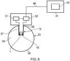
- Fig. 8shows a schematic view of a gas sensor 15 having both the emitter device 1 and the acoustic signal detector 16 assembled into an airway adapter 33.
- the gas sensor 15also comprises a current source 31 generating current for the device 1 or actually for its coil 4.
- the gas sensorfurther comprises a processing unit 32 for receiving a signal indicative of the concentration of the paramagnetic gas from the acoustic signal detector 16 and for receiving from the current source 31 a signal indicative of the pulsating current and its phase supplied to the coil 4.
- the processing unitis further controlling the operation of the current source 31. Based on the information collected from the current source 31 and the acoustic signal detector 16 the processing unit 32 is able to determine the paramagnetic gas concentration of the gas phase 17 between the emitter device and the acoustic signal detector 16.
- the gas sensor 15When measuring the patient gas, especially in neonatal and pediatric cases, it is crucial that the gas sensor 15 is fast, small and lightweight.
- the patientis connected to a ventilator using an intubation tube, a Y-piece, an inspiratory limb and an expiratory limb (not shown in Figures), but the airway adapter 33 may be connected to the intubation tube.
- the gas sensor 15is a so called mainstream gas sensor measuring gases flowing between the ventilator and the patient without drawing samples of the gas to a separate gas analyzer such as a sidestream gas analyzer which is at a distance from the flow between the ventilator and the patient. Naturally this same gas analyzer technology can also be exploited in sidestream gas analyzers.
- the gas analyzermay comprise also other technology such as an infrared technology than used for the measurement of oxygen in case gases like carbon dioxide, nitrous oxide or any volatile anesthetic agents such as halothane, enflurane, isoflurane, desflurane and sevoflurane is needed to measure. Additionally, there may be a spirometry adapter (not shown in Figures) for measuring the gas flow in the respiratory circuit.
- the gas to be measured in Fig 8flows through a gas channel 36 of the airway adapter 33.
- a cross section of the channeltypically may be circular or square.
- the gas sensor 15comprises a projective part 37, which can be pushed into the gas channel through the aperture 38 of the airway adapter 33.
- Both the device 1 and the acoustic signal detector 16are fixed on the projective part 37, advantageously on its tip, which may locate at a distance from an edge 39 of the airway adapter to avoid liquid drops moving along the edge 39 from disturbing the measurement.
- the gas sensor shown in Fig. 8is electrically connected via cable 40 to a patient monitor 41 having a display 42 for showing oxygen concentration measured.
- the adaptermay be made of a material allowing the acoustic signal generated by the device 1 to propagate through the material to the gas channel 36 inside the adapter and finally to the acoustic signal detector 16 especially in case the device 1 for generating the magnetic field and detector 16 are arranged outside the gas space of the adapter. Also only a part of the airway adapter, which is critical regarding acoustic wave propagation, may be provided with a material allowing the acoustic signal generated by the device 1 to propagate through the material to the gas channel 36 inside the adapter and to the acoustic signal detector.
- the same airway adapter 33may be equipped with a connection for this infrared technology (not shown in Figures).
- the airway adapter 33may be provided with at least one optical window for allowing the infrared radiation, which is used widely to analyze carbon dioxide, nitrous oxide and volatile anesthetic agents, to be absorbed due to the gas components.
- the infrared sourceis located in the gas analyzer on one side of the adapter and a non-dispersive filter assembly and an infrared detector or detectors on the opposite side in such a way the infrared radiation is directed from the infrared source through the windows and respective narrowband filters to the infrared detector.
- the signal from the infrared detectoris amplified and modified to reflect the concentration of the gas to be measured.
- a robust integrated solid-state O 2 sensitive device for generating magnetic field with minimal mechanical noise introducedwill open an opportunity to construct a new generation compact fast response mainstream 02 gas sensor in a number of robust planar solid-state configurations.
- This devicecould also be utilized to construct a small stand-alone oxygen sensor for measurement of ambient oxygen partial pressure for personal safety in surroundings like for example high altitudes or underground mines.
Landscapes
- Chemical & Material Sciences (AREA)
- Chemical Kinetics & Catalysis (AREA)
- Electrochemistry (AREA)
- Physics & Mathematics (AREA)
- Health & Medical Sciences (AREA)
- Life Sciences & Earth Sciences (AREA)
- Analytical Chemistry (AREA)
- Biochemistry (AREA)
- General Health & Medical Sciences (AREA)
- General Physics & Mathematics (AREA)
- Immunology (AREA)
- Pathology (AREA)
- Investigating Or Analyzing Materials By The Use Of Magnetic Means (AREA)
Description
- This disclosure relates generally to a gas sensor for a measurement of a paramagnetic gas component comprising a device for generating magnetic field comprising a coil responsive to an electric current and a magnetic core with poles for generating a magnetic field close to the poles making a paramagnetic gas component to vibrate and emit acoustic signal. The gas sensor also comprising an acoustic signal generator receiving the acoustic signal emitted by the paramagentic gas component
- In anesthesia or in intensive care, the condition of a patient is often monitored e.g. by analyzing the gas exhaled by the patient for its content. For this reason either a small portion of the respiratory gas is delivered to a gas analyzer or the gas analyzer is directly connected to the respiratory circuit. In the gas analyzer of mainstream type the whole volume or at least the main portion of the breathing air or gas mixture flows through the analyzer and its measuring chamber. The mainstream sensors on the market have mostly measured only one gas, carbon dioxide.
- Oxygen (O2) is a gas most vital for life of all living subjects and in healthcare technology there is a firm need to continuously measure its concentration especially under situations where patients breath artificial gas mixtures with O2 concentrations higher than 20.9% of the ambient air. This need is most obvious during anesthesia and intensive care. The measurement should be fast enough to be able to record oxygen values from both during inspiratory and expiratory phase of the breathing cycle. To be able to cover adequate range of breathing frequencies in children and adults, the response time should be of the order of 100 ms or better for both spontaneuos and artificial mechanical ventilation. This response time guarantees that in addition to recording inhaled O2 level one also gets accurate exhaled 02 level to confirm oxygen delivery to the pulmonary blood. This also makes it possible to calculate O2 uptake, if respitary flow is also being measured. Traditional electro-chemical O2 sensors have response time of typically a few seconds and even if they can be fabricated to achieve faster response times, it is on the cost of their life-time.
- Oxygen differs physically from all other relevant respiratory gases appearing in clinical environment by being a strongly paramagnetic. This means that a force is acting on O2 molecules in gradients of magnetic fields. Strictly speaking this force is proportional to the product of the field strength and its spatial gradient. Generating an alternating field in a gas filled gap of an electro-magnet makes the oxygen molecules in the gap and close to its edges vibrate and generate pressure signal in synchrony with the current applied to the coil of the magnet. The magnetic field strength is proportional to the flux density divided by the gap length and the pressure signal generated in an oscillating field proportional to the field squared. Even if this effect is macroscopically weak, it has been exploited commercially since 1970-80's in both industrial and clinical gas measurement applications in various technical configurations.
- The most widely used fast response differential paramagnetic O2 analyzer in operation room and critical care application requires measuring in the side-stream set-up, which means need for a gas sampling pump and a thin tubing to transport the gas from the patient airway to the measurement cell. This also generates a transport delay of typically 1 to 2 seconds between the signal measured vs. the real time concentration on the airway. The differential measurement based on this pneumatic bridge set-up also requires a reference gas to be suctioned into the sensor. In most cases ambient air can be used as a valid reference gas.
- There is also known a fast main-stream paramagnetic O2 analyzer requiring no pump neither reference gas comprising an open solenoid type of an acoustic emitter claimed to emit sound with intensity proportional to O2 concentration and a microphone for detection of amplitude of propagating sound generated. However, such a solenoid is a problematic component in this application because of dynamic magnetic forces acting on the coil generate unwanted magneto-mechanical interference signal in phase with the net signal generated by O2
- Prior art examples of paramagnetic gas sensors are known from
GB 2 158 949DE 42 01 216US 5 285 677 ,EP 1 775 582 andEP 1 217 369 . - The above-mentioned shortcomings, disadvantages and problems are addressed herein which will be understood by reading and understanding the following specification.
- In an embodiment, a device for generating magnetic field includes a coil responsive to an electric current and a magnetic core with poles for generating a magnetic field close to the poles making a paramagnetic gas component to vibrate and emit acoustic signal and which magnetic core is surrounded at least partly by the coil. The device for generating magnetic field also includes a substrate at least partly covered by the magnetic core and the coil.
- In another embodiment, a method for preparing a device for generating a magnetic field includes depositing a first coil layer on a substrate and depositing a magnetic core layer at least partly upon the first coil layer. The method for preparing a device for generating a magnetic field also includes depositing a second coil layer at least partly upon the magnetic core layer and connecting electrically the first coil layer to the second coil layer.
- In yet another embodiment a gas sensor for a measurement of a paramagnetic gas component includes a device for generating a magnetic field for vibrating a paramagnetic gas component, which device includes a coil responsive to an electric current and a magnetic core with poles for generating a magnetic field close to the poles making a paramagnetic gas component to vibrate and emit acoustic signal and which magnetic core is surrounded at least partly by the coil. The gas sensor for a measurement of a paramagnetic gas component also includes an acoustic signal detector receiving the acoustic signal emitted by the paramagnetic gas component. The device for generating a magnetic field also includes a substrate at least partly covered by the magnetic core and the coil.
- Various other features, objects, and advantages of the invention will be made apparent to those skilled in art from the accompanying drawings and detailed description thereof.
Fig.1 is a schematic view of a device for generating magnetic field in accordance with an embodiment;Fig.2 is a side view of a device ofFig. 1 having an open gap between poles of a magnetic core;Fig.3 is a side view of a device ofFig. 1 having a gap filled with dielectric material between poles of a magnetic core;Fig.4 is a cross section of the emitter device ofFigure 1 taken along lines A-A;Fig.5 is a schematic view of a device for generating magnetic field in accordance with another embodiment;Fig.6 is a schematic view of a cross section of a gas sensor comprising a device ofFig 5 for generating magnetic field taken along lines B-B and a signal detector in accordance with an embodiment;Fig.7 is a schematic view of a cross section of a gas sensor comprising a device ofFig 1 for generating magnetic field taken along lines A-A and a signal detector in accordance with another embodiment; andFig. 8 is a schematic view of a gas sensor assembled into an airway adapter for analyzing a paramagnetic gas component.- Specific embodiments are explained in the following detailed description making a reference to accompanying drawings. These detailed embodiments can naturally be modified and should not limit the scope of the invention as set forth in the claims.
- In
Fig. 1 a device 1 for generating a magnetic field is disclosed. The magnetic field in a gas space makes paramagnetic gas molecules to vibrate and emit acoustic signal such as sound waves useful while measuring a paramagnetic gas such as oxygen. The device 1 comprises asubstrate 2, which can be made of a mechanically robust dielectric material such as a ceramic material or glass. The device 1 also comprises amagnetic core 3 typically made of a ferromagnetic material forming a circular electromagnet core layer and acoil 4 made of an electrically conductive material such as copper. The coil may be driven by AC or pulsating current. Advantageously themagnetic core 3 surrounded at least partly by thecoil 4 is on a plane surface of the substrate. Thecoil 4 and themagnetic core 3 comprise thin integrated layers deposited on the substrate. The magnetic core may also be planar lying on the plane surface of the substrate. - The magnetic core with
poles waves emitting area 10 is created by a strong magnetic field in or around agap 5 between theopposite poles magnetic core 3 and its field gradients in proximity of its edges as shown inFig. 2 , where thegap 5 is open. One end of the gap, which is behind the gap, borders to thesubstrate 2, while its opposite end, which is away from the substrate, is in contact with ambient gas. The substrate edging the gap and opposite poles, acts as reflector of acoustic signals generated by vibrating paramagnetic gas molecules, which allows the gap emitting sound only to one direction. Basically this also means that by filling thegap 5 with a dielectric material 8 thearea 10 immediately upon it will still act as the acoustic emitter in presence of O2 due to the fringe field and its gradient as shown inFig. 3 . Thus the O2 molecules close to thegap 5 will still vibrate and emit acoustic waves. This filling will also contribute to minimizing the unwanted magneto-mechanical background signal. In the most basic version a single short gap with the magnetic field is acting as a line source of an acoustic wave with intensity proportional to ambient partial pressure of oxygen. The output for non-paramagnetic gases, like nitrogen, would be zero assuming mechanical vibration of the gap being negligible. - In the
substrate 2 behind thegap 5 can also be an aperture (not shown in Figures) through the substrate making possible also to generate the magnetic field and thus emit acoustic signals on opposite directions from the gap, one of directions being away from the substrate level as shown inFig. 2 and another being through the aperture of the substrate to the other side. This naturally reduces the magnetic field and the acoustic emission away from the substrate, when the magnetic field and the emission is now divided into two opposite directions, but the acoustic emission can be increased, if necessary by increasing the current supply to the coil. This kind of embodiment may be useful in applications like oxygen consumption measurement where both oxygen concentration and speed of gas by utilizing the frequency difference between two sound beams propagating to opposite directions (Doppler effect) could be measured concomitantly. Fig. 4 is a cross section of the emitter device ofFig 1 including an enlarged and more detailed view of the part where the magnetic core is surrounded by the coil. Thesemi-planar coil 4 around themagnetic core 3 can be constructed by depositing afirst coil layer 21 such as a bottom layer of a copper wire coil pattern on thesubstrate 2, which is then covered by afirst insulation layer 22 before depositing amagnetic core layer 23 of themagnetic core 3 as shown in the enlarged view ofFig. 4 . When themagnetic core layer 23 is in place, at least those parts of the magnetic core layer are covered by asecond insulation layer 24, which may be in contact with asecond coil layer 25 of thecoil 4 which is deposited above themagnetic core layer 23 on thesecond insulation layer 24 so that the top pattern gets properly positioned as to the lower one to form a functional coil around the planar magnetic core as shown inFig. 4 . The thin insulation layers 22 and 24 are needed on both sides of themagnetic core layer 23 to prevent short circuit in thecoil 4 if in contact with themagnetic core 3. Further it may be advantageous to make the entire planar structure inert by covering at least partly themagnetic core layer 23 or its top surface and/or thesecond coil layer 25 by adielectric layer 26, which top surface is away from the substrate, for protecting these components from corrosion and contamination. As shown inFig. 1 to reduce the current needed to run the magnetic flux density up to saturation at lower currents, it is advantageous to make the width of themagnetic core 3 tapering when nearing thegap 5, which can be open or closed.- Another possible embodiment for the device 1 is shown in
Fig. 5 where thegap 5 is not tapered, but it is spread over a wider area to make the magnetic field and the acoustic wave emitting area extending to become like a 2-dimensional plane source. This can be made in various geometries by configuration where thegap 5 comprises interlacedprotrusions 12 such as "fingers" with roots on theopposite poles magnetic core 3. These protrusions divide thegap 5 into several sub-gaps 13 enabling the wave front generated by a number of spatially distributed point sources to generate more directional sound beam than the cylindrical or spherical one generated by a single gap like inFig. 1 . Otherwise the structure ofFig. 5 is similar to the structure ofFig. 1 . - The dimensions of the device 1 can be scaled according to the requirements of the application. Typically an area of the substrate receiving the
magnetic core 3 and which can be used in a mainstream application where oxygen is measured from breathing gases of a patient, especially adults, could be 1 square inch and its thickness could be 3 to 5 mm. The thickness of the magnetic core layer could be from 0.2 to 0.5 mm and the thickness of the coil conduits around 0.1 mm. The air gap of the magnetic core could be 0.2 mm and the width of themagnetic core 5 mm with tapering down to 1 mm as shown inFig. 1 if more like a point source is preferred instead of a line source which is shown inFig. 6 . - To make a
gas sensor 15 for the paramagnetic gas, besides the device 1 for generating the magnetic field also anacoustic signal detector 16 such as a sound detector or microphone is needed to detect the acoustic wave to measure the amplitude of the acoustic wave as shown inFig. 6 and 7 and provide a signal indicative of the concentration of the paramagnetic gas. There are two major options for their mutual positioning. InFig. 6 theacoustic signal detector 16 is opposite the device 1 leaving there between agas space 17 with a gas mixture, which may include oxygen, which can be measured by thissensor 15. So the acoustic wave propagates through thegas space 17 making oxygen molecules in thegap 5, if not filled with the dielectric material, and around the gap close to its edges to vibrate generating acoustic signal such as the sound wave, which can be detected by thedetector 16. Another option for thegas sensor 15 is shown inFig. 7 where both the device 1 and thesound detector 16 can be placed side by side for instance on thesame substrate 2 or on the same wall using areflector 19, which can be the opposite wall itself or a separate structure close to the device 1. In this case the acoustic wave propagates through thegas space 17 to thereflector 19 reflecting the acoustic wave back across the gas space to theacoustic signal detector 16. Thereflector 19 can be designed to have a shape ensuring reflected sound getting focused optimally on the acoustic signal detector area. This integrated construction with thereflector 19 opens a convenient possibility to make the sensor to measure ambient O2 in any open space. - In accordance with an additional embodiment the empty space on the surface of the
substrate 2 inside or outside of themagnetic core 3 can be utilized for placement of extra sensors or sensor components, like ones for measuring the temperature and pressure (not shown in Figures) required for concentration vs. partial pressure calculations for instance in a complete mainstream gas sensor. As explained hereinbefore theacoustic signal detector 16 or the pressure sensor to measure the amplitude of the sound signal generated by O2 molecules can be placed on thesame substrate 2 with themagnetic core 3. Further related to the possibility for simultaneous flow measurement in phase with the O2 signal enabling real time O2 consumption calculation two sound detectors (not shown in Figures) can be placed on thesubstrate 2 in optimal positions to utilize Doppler shift to measure flows in both directions. Another option to the flow measurement is to place hot-wire flow sensor on the substrate (not shown in Figures). Fig. 8 shows a schematic view of agas sensor 15 having both the emitter device 1 and theacoustic signal detector 16 assembled into anairway adapter 33. To analyze the paramagnetic gas such as oxygen thegas sensor 15 also comprises acurrent source 31 generating current for the device 1 or actually for itscoil 4. The gas sensor further comprises aprocessing unit 32 for receiving a signal indicative of the concentration of the paramagnetic gas from theacoustic signal detector 16 and for receiving from the current source 31 a signal indicative of the pulsating current and its phase supplied to thecoil 4. The processing unit is further controlling the operation of thecurrent source 31. Based on the information collected from thecurrent source 31 and theacoustic signal detector 16 theprocessing unit 32 is able to determine the paramagnetic gas concentration of thegas phase 17 between the emitter device and theacoustic signal detector 16.- When measuring the patient gas, especially in neonatal and pediatric cases, it is crucial that the
gas sensor 15 is fast, small and lightweight. Typically the patient is connected to a ventilator using an intubation tube, a Y-piece, an inspiratory limb and an expiratory limb (not shown in Figures), but theairway adapter 33 may be connected to the intubation tube. Thegas sensor 15 is a so called mainstream gas sensor measuring gases flowing between the ventilator and the patient without drawing samples of the gas to a separate gas analyzer such as a sidestream gas analyzer which is at a distance from the flow between the ventilator and the patient. Naturally this same gas analyzer technology can also be exploited in sidestream gas analyzers. The gas analyzer may comprise also other technology such as an infrared technology than used for the measurement of oxygen in case gases like carbon dioxide, nitrous oxide or any volatile anesthetic agents such as halothane, enflurane, isoflurane, desflurane and sevoflurane is needed to measure. Additionally, there may be a spirometry adapter (not shown in Figures) for measuring the gas flow in the respiratory circuit. - The gas to be measured in
Fig 8 flows through agas channel 36 of theairway adapter 33. A cross section of the channel typically may be circular or square. Thegas sensor 15 comprises aprojective part 37, which can be pushed into the gas channel through theaperture 38 of theairway adapter 33. Both the device 1 and theacoustic signal detector 16 are fixed on theprojective part 37, advantageously on its tip, which may locate at a distance from anedge 39 of the airway adapter to avoid liquid drops moving along theedge 39 from disturbing the measurement. The gas sensor shown inFig. 8 is electrically connected viacable 40 to apatient monitor 41 having adisplay 42 for showing oxygen concentration measured. - The adapter may be made of a material allowing the acoustic signal generated by the device 1 to propagate through the material to the
gas channel 36 inside the adapter and finally to theacoustic signal detector 16 especially in case the device 1 for generating the magnetic field anddetector 16 are arranged outside the gas space of the adapter. Also only a part of the airway adapter, which is critical regarding acoustic wave propagation, may be provided with a material allowing the acoustic signal generated by the device 1 to propagate through the material to thegas channel 36 inside the adapter and to the acoustic signal detector. - If also an infrared technology is needed to measure other than the paramagnetic gas, then even the
same airway adapter 33 may be equipped with a connection for this infrared technology (not shown in Figures). In that case theairway adapter 33 may be provided with at least one optical window for allowing the infrared radiation, which is used widely to analyze carbon dioxide, nitrous oxide and volatile anesthetic agents, to be absorbed due to the gas components. Typically there are two infrared transmitting optical windows on the opposite sides of thegas channel 36. The infrared source is located in the gas analyzer on one side of the adapter and a non-dispersive filter assembly and an infrared detector or detectors on the opposite side in such a way the infrared radiation is directed from the infrared source through the windows and respective narrowband filters to the infrared detector. The signal from the infrared detector is amplified and modified to reflect the concentration of the gas to be measured. - In conclusion, compared to prior known devices for generating magnetic field the embodiments disclosed hereinbefore have several advantages. A robust integrated solid-state O2 sensitive device for generating magnetic field with minimal mechanical noise introduced will open an opportunity to construct a new generation compact fast response mainstream 02 gas sensor in a number of robust planar solid-state configurations. This device could also be utilized to construct a small stand-alone oxygen sensor for measurement of ambient oxygen partial pressure for personal safety in surroundings like for example high altitudes or underground mines.
- The written description uses examples to disclose the invention, including the best mode, and also to enable any person skilled in the art to make and use the invention. The patentable scope of the invention is defined by the claims, and may include other examples that occur to those skilled in the art. Such other examples are intended to be within the scope of the claims if they have structural elements that do not differ from the literal language of the claims, or if they include equivalent structural elements with insubstantial differences from the literal languages of the claims.
Claims (11)
- A gas sensor for a measurement of a paramagnetic gas component comprising:a device (1) for generating a magnetic field for vibrating a paramagnetic gas component, which device comprising a coil (4) responsive to an electric current; and a magnetic core (3) with poles (6,7) for generating a magnetic field close to said poles making a paramagnetic gas component to vibrate and emit acoustic signal and which magnetic core is surrounded at least partly by said coil (4); andan acoustic signal detector (16) receiving the acoustic signal emitted by the paramagnetic gas component,characterized in that said device (1) for generating a magnetic field also comprising a substrate (2) having deposited on it said magnetic core (3) and said coil (4).
- The gas sensor according to claim 1,characterized in that said coil (4) comprises a first coil layer (21) deposited first on said substrate and a second coil layer (25) deposited over said magnetic core deposited at least partly over said first coil layer.
- The gas sensor according to claim 2,characterized in that said magnetic core (3) comprises a magnetic core layer (23) in which case said magnetic core and said coil on said substrate comprise different layers, which are a first coil layer (21) deposited on said substrate, a magnetic core layer (23) deposited at least partly over said first coil layer and a second coil layer (25) deposited over said magnetic core layer and electrically connected to said first coil layer.
- The gas sensor according to claim 3,characterized in that a first insulation layer (22) is provided between said first coil layer (21) and said magnetic core layer (23) and a second insulation layer (24) is provided between said magnetic core layer and said second coil layer (25).
- The gas sensor according to claim 1,characterized in that said substrate is made of a dielectric material, which is mechanically robust.
- The gas sensor according to claim 1,characterized in that said device for generating magnetic field further comprising a gap (5) between said poles, which gap can be open or filled.
- The gas sensor according to claim 1,characterized in that the magnetic field generated close to said poles is between or around said poles.
- The gas sensor according to claim 1,characterized in that a width of said magnetic core (3) is tapering when nearing a gap (5) between said poles (6,7).
- The gas sensor according to claim 1,characterized in that between opposite poles (6,7) there is a gap (5) comprising interlaced protrusions (12) with roots on said opposite poles (6, 7) of said magnetic core (3).
- The gas sensor according to claim 9,characterized in that said protrusions (12) divide said gap (5) into several subgaps (13).
- The gas sensor according to claim 1 further comprising:a current source (31) generating electric current for said device (1) for generating magnetic field and providing a signal indicative of the current supplied; anda processing unit (32) for receiving a signal indicative of a concentration of the paramagnetic gas component from said acoustic signal detector (16) and for receiving from said current source (31) a signal indicative of the current supplied to the coil (4), and based on the information collected from the current source (31) and the sound detector (16) the processing unit (32) is able to determine the paramagnetic gas concentration.
Priority Applications (3)
| Application Number | Priority Date | Filing Date | Title |
|---|---|---|---|
| EP11163327.7AEP2515105B1 (en) | 2011-04-21 | 2011-04-21 | Gas sensor for measurement of paramagnetic gas component |
| US13/451,609US9557298B2 (en) | 2011-04-21 | 2012-04-20 | Device for generating magnetic field, method for preparing such device and gas sensor for measurement of paramagnetic gas component |
| CN2012102491916ACN102788838A (en) | 2011-04-21 | 2012-04-21 | Device for generating magnetic field, method for preparing such device and gas sensor for measurement of paramagnetic gas component |
Applications Claiming Priority (1)
| Application Number | Priority Date | Filing Date | Title |
|---|---|---|---|
| EP11163327.7AEP2515105B1 (en) | 2011-04-21 | 2011-04-21 | Gas sensor for measurement of paramagnetic gas component |
Publications (2)
| Publication Number | Publication Date |
|---|---|
| EP2515105A1 EP2515105A1 (en) | 2012-10-24 |
| EP2515105B1true EP2515105B1 (en) | 2019-01-02 |
Family
ID=44648329
Family Applications (1)
| Application Number | Title | Priority Date | Filing Date |
|---|---|---|---|
| EP11163327.7AActiveEP2515105B1 (en) | 2011-04-21 | 2011-04-21 | Gas sensor for measurement of paramagnetic gas component |
Country Status (3)
| Country | Link |
|---|---|
| US (1) | US9557298B2 (en) |
| EP (1) | EP2515105B1 (en) |
| CN (1) | CN102788838A (en) |
Families Citing this family (5)
| Publication number | Priority date | Publication date | Assignee | Title |
|---|---|---|---|---|
| JP2015055566A (en)* | 2013-09-12 | 2015-03-23 | 富士電機株式会社 | Magnetic oxygen analyzer |
| DE102015205118B4 (en)* | 2015-03-20 | 2017-05-18 | Siemens Aktiengesellschaft | Paramagnetic gas sensor |
| EP3838320B1 (en)* | 2018-08-17 | 2024-07-31 | Shenzhen Mindray Bio-Medical Electronics Co., Ltd | Ventilation apparatus |
| CN111243824B (en)* | 2018-11-28 | 2025-04-25 | 中国科学院深圳先进技术研究院 | A magnetic field generating device |
| CN116568352A (en)* | 2020-12-30 | 2023-08-08 | 深圳迈瑞生物医疗电子股份有限公司 | Paramagnetic gas measuring device and medical ventilation system |
Citations (1)
| Publication number | Priority date | Publication date | Assignee | Title |
|---|---|---|---|---|
| GB2158949A (en)* | 1984-05-16 | 1985-11-20 | Instrumentarium Corp | Quick response paramagnetic analyzer for measurement of the oxygen content of gases |
Family Cites Families (25)
| Publication number | Priority date | Publication date | Assignee | Title |
|---|---|---|---|---|
| US3049665A (en)* | 1958-07-10 | 1962-08-14 | Hummel Heinz | Measuring instrument and method |
| DE1648924B2 (en)* | 1967-08-31 | 1975-05-15 | Heinz Dr. Rer.Nat. 6240 Koenigstein-Johanniswald Hummel | Device for analyzing gases for components with paramagnetic susceptibility |
| DE2017423B2 (en)* | 1970-04-11 | 1977-12-08 | Hartmann & Braun Ag, 6000 Frankfurt | GAS ANALYZER BASED ON THE MAGNETIC PROPERTIES OF A GAS |
| US4359706A (en)* | 1979-12-18 | 1982-11-16 | Arnold Flack | Magnet pole pieces and pole piece extensions and shields |
| DE3145542C2 (en)* | 1981-11-17 | 1985-12-12 | Drägerwerk AG, 2400 Lübeck | Paramagnetic O2 sensor |
| US4667157A (en)* | 1984-04-03 | 1987-05-19 | The Babcock & Wilcox Company | Linear Hall effect oxygen sensor with auxiliary coil magnetic field balancing |
| DE3566185D1 (en)* | 1984-04-11 | 1988-12-15 | Sumitomo Spec Metals | Magnetic field generating device for nmr-ct |
| US4563894A (en) | 1984-08-21 | 1986-01-14 | Hewlett-Packard Company | Paramagnetic oxygen sensor |
| JPS63241905A (en)* | 1987-03-27 | 1988-10-07 | Sumitomo Special Metals Co Ltd | Magnetic field generating equipment |
| DE3840337C1 (en)* | 1988-11-30 | 1989-11-02 | Draegerwerk Ag, 2400 Luebeck, De | |
| EP0456787B1 (en)* | 1989-12-08 | 1994-07-27 | OEHLER, Oscar, Dr. | Selective gas detection by field separation and sound velocity measurement: detection of oxygen |
| DE4201216C1 (en)* | 1992-01-18 | 1993-02-25 | Gms Gesellschaft Fuer Mikrotechnik Und Sensorik Mbh, 7742 St Georgen, De | Oxygen@ sensor for gas mixt. - measures difference in flow speed in two stream channels etched into wafer substrate by two thermo anemometers |
| CN2135152Y (en)* | 1992-09-04 | 1993-06-02 | 中国矿业大学 | Ferromagnetic Substance Detection Sensor |
| JP3266355B2 (en)* | 1993-02-05 | 2002-03-18 | 住友特殊金属株式会社 | Magnetic field generator for superconducting MRI |
| US5539366A (en)* | 1994-07-27 | 1996-07-23 | General Electric Company | Magnet having contoured pole faces for magnetic field homogeneity |
| US6263722B1 (en)* | 1998-09-12 | 2001-07-24 | Hartmann & Braun Gmbh & Co. Kg | Magnetomechanical gas analyzer, in particular paramagnetic oxygen analyzer |
| US20020062681A1 (en)* | 2000-11-30 | 2002-05-30 | Livingston Richard A. | Oxygen sensor and flow meter device |
| EP1217369A1 (en)* | 2000-12-22 | 2002-06-26 | Instrumentarium Corporation | A sensor for measuring paramagnetic gas like oxygen in a mixture |
| JP2005523460A (en)* | 2002-04-19 | 2005-08-04 | ワブバンク インコーポレイテッド | Method, apparatus and system for sample detection based on low frequency spectral components |
| EP1754063A1 (en)* | 2004-05-24 | 2007-02-21 | Koninklijke Philips Electronics N.V. | Magneto-resistive sensor for high sensitivity depth probing |
| EP1775582A1 (en)* | 2005-10-14 | 2007-04-18 | General Electric Company | Paramagnetic gas analyzer with detector mounting |
| EP1840563B1 (en)* | 2006-03-29 | 2012-07-25 | General Electric Company | Measuring gas components together with a paramagnetic gas |
| CN102027361B (en)* | 2008-05-14 | 2013-02-27 | 皇家飞利浦电子股份有限公司 | Oxygen concentration measurement using GMR |
| US20100140519A1 (en)* | 2008-12-04 | 2010-06-10 | General Electric Company | Electromagnetic actuators |
| CA2868986C (en)* | 2011-03-30 | 2021-07-27 | Ambature Inc. | Electrical, mechanical, computing, and/or other devices formed of extremely low resistance materials |
- 2011
- 2011-04-21EPEP11163327.7Apatent/EP2515105B1/enactiveActive
- 2012
- 2012-04-20USUS13/451,609patent/US9557298B2/enactiveActive
- 2012-04-21CNCN2012102491916Apatent/CN102788838A/enactivePending
Patent Citations (1)
| Publication number | Priority date | Publication date | Assignee | Title |
|---|---|---|---|---|
| GB2158949A (en)* | 1984-05-16 | 1985-11-20 | Instrumentarium Corp | Quick response paramagnetic analyzer for measurement of the oxygen content of gases |
Also Published As
| Publication number | Publication date |
|---|---|
| EP2515105A1 (en) | 2012-10-24 |
| CN102788838A (en) | 2012-11-21 |
| US20120266656A1 (en) | 2012-10-25 |
| US9557298B2 (en) | 2017-01-31 |
Similar Documents
| Publication | Publication Date | Title |
|---|---|---|
| EP2515105B1 (en) | Gas sensor for measurement of paramagnetic gas component | |
| JP5771181B2 (en) | Sensor chip provided in a measurement air chamber for analyzing a gas containing a plurality of components | |
| US6272905B1 (en) | Method and apparatus for real time gas analysis | |
| CN102264292B (en) | A device for measuring the concentration of gases in the breath | |
| US9855010B2 (en) | Mainstream gas analyzer configurable to removably couple with a sidestream gas sampling component | |
| EP2818107B1 (en) | On-airway pulmonary function tester | |
| JP2003505180A (en) | Metabolic calorimeter using respiratory gas analysis | |
| US9347932B2 (en) | Device and method for breath analysis using acoustic resonance flow rate | |
| US20080077038A1 (en) | Respiratory Volume/Flow Gating, Monitoring, and Spirometry System for Mri | |
| US8328729B2 (en) | Acoustic plethysmograph for measuring pulmonary function | |
| US20130018288A1 (en) | System for monitoring ongoing cardiopulmonary resuscitation | |
| Sinharay et al. | The ultrasonic directional tidal breathing pattern sensor: Equitable design realization based on phase information | |
| EP2745775A1 (en) | Device for measuring respiratory gas property, airway adapter and gas analyzing unit for respiratory gas analysis | |
| US9295410B2 (en) | Airway adapter and gas analyzer for measuring oxygen concentration of a respiratory gas | |
| US8194249B2 (en) | Gas analyzer | |
| US20210290101A1 (en) | Respiratory diagnostic tool and method | |
| WO2015198301A1 (en) | Nano-opto-mechanical sensor | |
| Eisenkraft et al. | Respiratory gas monitoring | |
| WO2009103111A1 (en) | Patient's breathing detection and monitoring | |
| Reader | Anesthetic Gas Monitoring | |
| EP2330417B1 (en) | System and method for measuring concentration of a paramagnetic gas | |
| JPH0374571B2 (en) | ||
| Gedeon et al. | A FAST RESPONSE ANALYZER FOR SIMULTANOUS ON-LINE MEASUREMENT OF N₂O AND HALOTHANE OR N2O AND ENFLURANE | |
| Westhorpe et al. | Anaesthetic agent monitoring |
Legal Events
| Date | Code | Title | Description |
|---|---|---|---|
| PUAI | Public reference made under article 153(3) epc to a published international application that has entered the european phase | Free format text:ORIGINAL CODE: 0009012 | |
| AK | Designated contracting states | Kind code of ref document:A1 Designated state(s):AL AT BE BG CH CY CZ DE DK EE ES FI FR GB GR HR HU IE IS IT LI LT LU LV MC MK MT NL NO PL PT RO RS SE SI SK SM TR | |
| AX | Request for extension of the european patent | Extension state:BA ME | |
| 17P | Request for examination filed | Effective date:20130424 | |
| GRAP | Despatch of communication of intention to grant a patent | Free format text:ORIGINAL CODE: EPIDOSNIGR1 | |
| STAA | Information on the status of an ep patent application or granted ep patent | Free format text:STATUS: GRANT OF PATENT IS INTENDED | |
| INTG | Intention to grant announced | Effective date:20180807 | |
| GRAS | Grant fee paid | Free format text:ORIGINAL CODE: EPIDOSNIGR3 | |
| GRAA | (expected) grant | Free format text:ORIGINAL CODE: 0009210 | |
| STAA | Information on the status of an ep patent application or granted ep patent | Free format text:STATUS: THE PATENT HAS BEEN GRANTED | |
| AK | Designated contracting states | Kind code of ref document:B1 Designated state(s):AL AT BE BG CH CY CZ DE DK EE ES FI FR GB GR HR HU IE IS IT LI LT LU LV MC MK MT NL NO PL PT RO RS SE SI SK SM TR | |
| REG | Reference to a national code | Ref country code:GB Ref legal event code:FG4D | |
| REG | Reference to a national code | Ref country code:CH Ref legal event code:EP Ref country code:AT Ref legal event code:REF Ref document number:1085040 Country of ref document:AT Kind code of ref document:T Effective date:20190115 | |
| REG | Reference to a national code | Ref country code:IE Ref legal event code:FG4D | |
| REG | Reference to a national code | Ref country code:DE Ref legal event code:R096 Ref document number:602011055295 Country of ref document:DE | |
| REG | Reference to a national code | Ref country code:NL Ref legal event code:MP Effective date:20190102 | |
| REG | Reference to a national code | Ref country code:LT Ref legal event code:MG4D | |
| REG | Reference to a national code | Ref country code:AT Ref legal event code:MK05 Ref document number:1085040 Country of ref document:AT Kind code of ref document:T Effective date:20190102 | |
| PG25 | Lapsed in a contracting state [announced via postgrant information from national office to epo] | Ref country code:NL Free format text:LAPSE BECAUSE OF FAILURE TO SUBMIT A TRANSLATION OF THE DESCRIPTION OR TO PAY THE FEE WITHIN THE PRESCRIBED TIME-LIMIT Effective date:20190102 | |
| PG25 | Lapsed in a contracting state [announced via postgrant information from national office to epo] | Ref country code:PL Free format text:LAPSE BECAUSE OF FAILURE TO SUBMIT A TRANSLATION OF THE DESCRIPTION OR TO PAY THE FEE WITHIN THE PRESCRIBED TIME-LIMIT Effective date:20190102 Ref country code:NO Free format text:LAPSE BECAUSE OF FAILURE TO SUBMIT A TRANSLATION OF THE DESCRIPTION OR TO PAY THE FEE WITHIN THE PRESCRIBED TIME-LIMIT Effective date:20190402 Ref country code:LT Free format text:LAPSE BECAUSE OF FAILURE TO SUBMIT A TRANSLATION OF THE DESCRIPTION OR TO PAY THE FEE WITHIN THE PRESCRIBED TIME-LIMIT Effective date:20190102 Ref country code:ES Free format text:LAPSE BECAUSE OF FAILURE TO SUBMIT A TRANSLATION OF THE DESCRIPTION OR TO PAY THE FEE WITHIN THE PRESCRIBED TIME-LIMIT Effective date:20190102 Ref country code:PT Free format text:LAPSE BECAUSE OF FAILURE TO SUBMIT A TRANSLATION OF THE DESCRIPTION OR TO PAY THE FEE WITHIN THE PRESCRIBED TIME-LIMIT Effective date:20190502 Ref country code:SE Free format text:LAPSE BECAUSE OF FAILURE TO SUBMIT A TRANSLATION OF THE DESCRIPTION OR TO PAY THE FEE WITHIN THE PRESCRIBED TIME-LIMIT Effective date:20190102 Ref country code:FI Free format text:LAPSE BECAUSE OF FAILURE TO SUBMIT A TRANSLATION OF THE DESCRIPTION OR TO PAY THE FEE WITHIN THE PRESCRIBED TIME-LIMIT Effective date:20190102 | |
| PG25 | Lapsed in a contracting state [announced via postgrant information from national office to epo] | Ref country code:LV Free format text:LAPSE BECAUSE OF FAILURE TO SUBMIT A TRANSLATION OF THE DESCRIPTION OR TO PAY THE FEE WITHIN THE PRESCRIBED TIME-LIMIT Effective date:20190102 Ref country code:IS Free format text:LAPSE BECAUSE OF FAILURE TO SUBMIT A TRANSLATION OF THE DESCRIPTION OR TO PAY THE FEE WITHIN THE PRESCRIBED TIME-LIMIT Effective date:20190502 Ref country code:BG Free format text:LAPSE BECAUSE OF FAILURE TO SUBMIT A TRANSLATION OF THE DESCRIPTION OR TO PAY THE FEE WITHIN THE PRESCRIBED TIME-LIMIT Effective date:20190402 Ref country code:RS Free format text:LAPSE BECAUSE OF FAILURE TO SUBMIT A TRANSLATION OF THE DESCRIPTION OR TO PAY THE FEE WITHIN THE PRESCRIBED TIME-LIMIT Effective date:20190102 Ref country code:HR Free format text:LAPSE BECAUSE OF FAILURE TO SUBMIT A TRANSLATION OF THE DESCRIPTION OR TO PAY THE FEE WITHIN THE PRESCRIBED TIME-LIMIT Effective date:20190102 Ref country code:GR Free format text:LAPSE BECAUSE OF FAILURE TO SUBMIT A TRANSLATION OF THE DESCRIPTION OR TO PAY THE FEE WITHIN THE PRESCRIBED TIME-LIMIT Effective date:20190403 | |
| REG | Reference to a national code | Ref country code:DE Ref legal event code:R097 Ref document number:602011055295 Country of ref document:DE | |
| PG25 | Lapsed in a contracting state [announced via postgrant information from national office to epo] | Ref country code:AL Free format text:LAPSE BECAUSE OF FAILURE TO SUBMIT A TRANSLATION OF THE DESCRIPTION OR TO PAY THE FEE WITHIN THE PRESCRIBED TIME-LIMIT Effective date:20190102 Ref country code:DK Free format text:LAPSE BECAUSE OF FAILURE TO SUBMIT A TRANSLATION OF THE DESCRIPTION OR TO PAY THE FEE WITHIN THE PRESCRIBED TIME-LIMIT Effective date:20190102 Ref country code:SK Free format text:LAPSE BECAUSE OF FAILURE TO SUBMIT A TRANSLATION OF THE DESCRIPTION OR TO PAY THE FEE WITHIN THE PRESCRIBED TIME-LIMIT Effective date:20190102 Ref country code:RO Free format text:LAPSE BECAUSE OF FAILURE TO SUBMIT A TRANSLATION OF THE DESCRIPTION OR TO PAY THE FEE WITHIN THE PRESCRIBED TIME-LIMIT Effective date:20190102 Ref country code:EE Free format text:LAPSE BECAUSE OF FAILURE TO SUBMIT A TRANSLATION OF THE DESCRIPTION OR TO PAY THE FEE WITHIN THE PRESCRIBED TIME-LIMIT Effective date:20190102 Ref country code:CZ Free format text:LAPSE BECAUSE OF FAILURE TO SUBMIT A TRANSLATION OF THE DESCRIPTION OR TO PAY THE FEE WITHIN THE PRESCRIBED TIME-LIMIT Effective date:20190102 Ref country code:IT Free format text:LAPSE BECAUSE OF FAILURE TO SUBMIT A TRANSLATION OF THE DESCRIPTION OR TO PAY THE FEE WITHIN THE PRESCRIBED TIME-LIMIT Effective date:20190102 Ref country code:AT Free format text:LAPSE BECAUSE OF FAILURE TO SUBMIT A TRANSLATION OF THE DESCRIPTION OR TO PAY THE FEE WITHIN THE PRESCRIBED TIME-LIMIT Effective date:20190102 | |
| PLBE | No opposition filed within time limit | Free format text:ORIGINAL CODE: 0009261 | |
| STAA | Information on the status of an ep patent application or granted ep patent | Free format text:STATUS: NO OPPOSITION FILED WITHIN TIME LIMIT | |
| PG25 | Lapsed in a contracting state [announced via postgrant information from national office to epo] | Ref country code:SM Free format text:LAPSE BECAUSE OF FAILURE TO SUBMIT A TRANSLATION OF THE DESCRIPTION OR TO PAY THE FEE WITHIN THE PRESCRIBED TIME-LIMIT Effective date:20190102 | |
| REG | Reference to a national code | Ref country code:CH Ref legal event code:PL | |
| 26N | No opposition filed | Effective date:20191003 | |
| REG | Reference to a national code | Ref country code:BE Ref legal event code:MM Effective date:20190430 | |
| PG25 | Lapsed in a contracting state [announced via postgrant information from national office to epo] | Ref country code:LU Free format text:LAPSE BECAUSE OF NON-PAYMENT OF DUE FEES Effective date:20190421 Ref country code:MC Free format text:LAPSE BECAUSE OF FAILURE TO SUBMIT A TRANSLATION OF THE DESCRIPTION OR TO PAY THE FEE WITHIN THE PRESCRIBED TIME-LIMIT Effective date:20190102 | |
| PG25 | Lapsed in a contracting state [announced via postgrant information from national office to epo] | Ref country code:LI Free format text:LAPSE BECAUSE OF NON-PAYMENT OF DUE FEES Effective date:20190430 Ref country code:CH Free format text:LAPSE BECAUSE OF NON-PAYMENT OF DUE FEES Effective date:20190430 | |
| PG25 | Lapsed in a contracting state [announced via postgrant information from national office to epo] | Ref country code:BE Free format text:LAPSE BECAUSE OF NON-PAYMENT OF DUE FEES Effective date:20190430 Ref country code:FR Free format text:LAPSE BECAUSE OF NON-PAYMENT OF DUE FEES Effective date:20190430 Ref country code:SI Free format text:LAPSE BECAUSE OF FAILURE TO SUBMIT A TRANSLATION OF THE DESCRIPTION OR TO PAY THE FEE WITHIN THE PRESCRIBED TIME-LIMIT Effective date:20190102 | |
| PG25 | Lapsed in a contracting state [announced via postgrant information from national office to epo] | Ref country code:TR Free format text:LAPSE BECAUSE OF FAILURE TO SUBMIT A TRANSLATION OF THE DESCRIPTION OR TO PAY THE FEE WITHIN THE PRESCRIBED TIME-LIMIT Effective date:20190102 | |
| PG25 | Lapsed in a contracting state [announced via postgrant information from national office to epo] | Ref country code:IE Free format text:LAPSE BECAUSE OF NON-PAYMENT OF DUE FEES Effective date:20190421 | |
| PG25 | Lapsed in a contracting state [announced via postgrant information from national office to epo] | Ref country code:CY Free format text:LAPSE BECAUSE OF FAILURE TO SUBMIT A TRANSLATION OF THE DESCRIPTION OR TO PAY THE FEE WITHIN THE PRESCRIBED TIME-LIMIT Effective date:20190102 | |
| PG25 | Lapsed in a contracting state [announced via postgrant information from national office to epo] | Ref country code:MT Free format text:LAPSE BECAUSE OF FAILURE TO SUBMIT A TRANSLATION OF THE DESCRIPTION OR TO PAY THE FEE WITHIN THE PRESCRIBED TIME-LIMIT Effective date:20190102 Ref country code:HU Free format text:LAPSE BECAUSE OF FAILURE TO SUBMIT A TRANSLATION OF THE DESCRIPTION OR TO PAY THE FEE WITHIN THE PRESCRIBED TIME-LIMIT; INVALID AB INITIO Effective date:20110421 | |
| PG25 | Lapsed in a contracting state [announced via postgrant information from national office to epo] | Ref country code:MK Free format text:LAPSE BECAUSE OF FAILURE TO SUBMIT A TRANSLATION OF THE DESCRIPTION OR TO PAY THE FEE WITHIN THE PRESCRIBED TIME-LIMIT Effective date:20190102 | |
| P01 | Opt-out of the competence of the unified patent court (upc) registered | Effective date:20230528 | |
| PGFP | Annual fee paid to national office [announced via postgrant information from national office to epo] | Ref country code:GB Payment date:20250319 Year of fee payment:15 | |
| PGFP | Annual fee paid to national office [announced via postgrant information from national office to epo] | Ref country code:DE Payment date:20250319 Year of fee payment:15 | |
| REG | Reference to a national code | Ref country code:DE Ref legal event code:R081 Ref document number:602011055295 Country of ref document:DE Owner name:GE PRECISION HEALTHCARE LLC, WAUKESHA, US Free format text:FORMER OWNER: GENERAL ELECTRIC COMPANY, SCHENECTADY, N.Y., US | |
| REG | Reference to a national code | Ref country code:GB Ref legal event code:732E Free format text:REGISTERED BETWEEN 20250807 AND 20250813 |