EP2514621B1 - Fuel tank valve device - Google Patents
Fuel tank valve deviceDownload PDFInfo
- Publication number
- EP2514621B1 EP2514621B1EP10837506.4AEP10837506AEP2514621B1EP 2514621 B1EP2514621 B1EP 2514621B1EP 10837506 AEP10837506 AEP 10837506AEP 2514621 B1EP2514621 B1EP 2514621B1
- Authority
- EP
- European Patent Office
- Prior art keywords
- float body
- case
- guide shaft
- air flow
- hole
- Prior art date
- Legal status (The legal status is an assumption and is not a legal conclusion. Google has not performed a legal analysis and makes no representation as to the accuracy of the status listed.)
- Active
Links
- 239000002828fuel tankSubstances0.000titleclaimsdescription24
- 239000000446fuelSubstances0.000claimsdescription44
- 238000005192partitionMethods0.000claimsdescription28
- 230000037431insertionEffects0.000claimsdescription26
- 238000003780insertionMethods0.000claimsdescription26
- 230000008878couplingEffects0.000claimsdescription10
- 238000010168coupling processMethods0.000claimsdescription10
- 238000005859coupling reactionMethods0.000claimsdescription10
- 230000001174ascending effectEffects0.000claimsdescription6
- 239000013013elastic materialSubstances0.000claimsdescription6
- 230000005489elastic deformationEffects0.000claimsdescription5
- 239000000945fillerSubstances0.000description9
- 238000004519manufacturing processMethods0.000description4
- 210000000078clawAnatomy0.000description3
- 230000007423decreaseEffects0.000description3
- 238000001514detection methodMethods0.000description3
- 238000007789sealingMethods0.000description3
- 230000006835compressionEffects0.000description2
- 238000007906compressionMethods0.000description2
- 239000000463materialSubstances0.000description2
- 239000003566sealing materialSubstances0.000description2
- 208000031872Body RemainsDiseases0.000description1
- 230000000694effectsEffects0.000description1
- 238000005516engineering processMethods0.000description1
- 238000002347injectionMethods0.000description1
- 239000007924injectionSubstances0.000description1
- 238000009434installationMethods0.000description1
- 238000003466weldingMethods0.000description1
Images


Classifications
- B—PERFORMING OPERATIONS; TRANSPORTING
- B60—VEHICLES IN GENERAL
- B60K—ARRANGEMENT OR MOUNTING OF PROPULSION UNITS OR OF TRANSMISSIONS IN VEHICLES; ARRANGEMENT OR MOUNTING OF PLURAL DIVERSE PRIME-MOVERS IN VEHICLES; AUXILIARY DRIVES FOR VEHICLES; INSTRUMENTATION OR DASHBOARDS FOR VEHICLES; ARRANGEMENTS IN CONNECTION WITH COOLING, AIR INTAKE, GAS EXHAUST OR FUEL SUPPLY OF PROPULSION UNITS IN VEHICLES
- B60K15/00—Arrangement in connection with fuel supply of combustion engines or other fuel consuming energy converters, e.g. fuel cells; Mounting or construction of fuel tanks
- B60K15/01—Arrangement of fuel conduits
- B—PERFORMING OPERATIONS; TRANSPORTING
- B60—VEHICLES IN GENERAL
- B60K—ARRANGEMENT OR MOUNTING OF PROPULSION UNITS OR OF TRANSMISSIONS IN VEHICLES; ARRANGEMENT OR MOUNTING OF PLURAL DIVERSE PRIME-MOVERS IN VEHICLES; AUXILIARY DRIVES FOR VEHICLES; INSTRUMENTATION OR DASHBOARDS FOR VEHICLES; ARRANGEMENTS IN CONNECTION WITH COOLING, AIR INTAKE, GAS EXHAUST OR FUEL SUPPLY OF PROPULSION UNITS IN VEHICLES
- B60K15/00—Arrangement in connection with fuel supply of combustion engines or other fuel consuming energy converters, e.g. fuel cells; Mounting or construction of fuel tanks
- B60K15/03—Fuel tanks
- B60K15/035—Fuel tanks characterised by venting means
- B60K15/03519—Valve arrangements in the vent line
- F—MECHANICAL ENGINEERING; LIGHTING; HEATING; WEAPONS; BLASTING
- F02—COMBUSTION ENGINES; HOT-GAS OR COMBUSTION-PRODUCT ENGINE PLANTS
- F02M—SUPPLYING COMBUSTION ENGINES IN GENERAL WITH COMBUSTIBLE MIXTURES OR CONSTITUENTS THEREOF
- F02M37/00—Apparatus or systems for feeding liquid fuel from storage containers to carburettors or fuel-injection apparatus; Arrangements for purifying liquid fuel specially adapted for, or arranged on, internal-combustion engines
- F—MECHANICAL ENGINEERING; LIGHTING; HEATING; WEAPONS; BLASTING
- F16—ENGINEERING ELEMENTS AND UNITS; GENERAL MEASURES FOR PRODUCING AND MAINTAINING EFFECTIVE FUNCTIONING OF MACHINES OR INSTALLATIONS; THERMAL INSULATION IN GENERAL
- F16K—VALVES; TAPS; COCKS; ACTUATING-FLOATS; DEVICES FOR VENTING OR AERATING
- F16K24/00—Devices, e.g. valves, for venting or aerating enclosures
- F16K24/04—Devices, e.g. valves, for venting or aerating enclosures for venting only
- F16K24/042—Devices, e.g. valves, for venting or aerating enclosures for venting only actuated by a float
- F16K24/044—Devices, e.g. valves, for venting or aerating enclosures for venting only actuated by a float the float being rigidly connected to the valve element, the assembly of float and valve element following a substantially translational movement when actuated, e.g. also for actuating a pilot valve
- F—MECHANICAL ENGINEERING; LIGHTING; HEATING; WEAPONS; BLASTING
- F16—ENGINEERING ELEMENTS AND UNITS; GENERAL MEASURES FOR PRODUCING AND MAINTAINING EFFECTIVE FUNCTIONING OF MACHINES OR INSTALLATIONS; THERMAL INSULATION IN GENERAL
- F16K—VALVES; TAPS; COCKS; ACTUATING-FLOATS; DEVICES FOR VENTING OR AERATING
- F16K31/00—Actuating devices; Operating means; Releasing devices
- F16K31/12—Actuating devices; Operating means; Releasing devices actuated by fluid
- F16K31/18—Actuating devices; Operating means; Releasing devices actuated by fluid actuated by a float
- B—PERFORMING OPERATIONS; TRANSPORTING
- B60—VEHICLES IN GENERAL
- B60K—ARRANGEMENT OR MOUNTING OF PROPULSION UNITS OR OF TRANSMISSIONS IN VEHICLES; ARRANGEMENT OR MOUNTING OF PLURAL DIVERSE PRIME-MOVERS IN VEHICLES; AUXILIARY DRIVES FOR VEHICLES; INSTRUMENTATION OR DASHBOARDS FOR VEHICLES; ARRANGEMENTS IN CONNECTION WITH COOLING, AIR INTAKE, GAS EXHAUST OR FUEL SUPPLY OF PROPULSION UNITS IN VEHICLES
- B60K15/00—Arrangement in connection with fuel supply of combustion engines or other fuel consuming energy converters, e.g. fuel cells; Mounting or construction of fuel tanks
- B60K15/03—Fuel tanks
- B60K15/035—Fuel tanks characterised by venting means
- B60K2015/03561—Venting means working at specific times
- B60K2015/03566—Venting means working at specific times comprising means for stopping the venting of fuel vapor, e.g. during refuelling or engine stop
- Y—GENERAL TAGGING OF NEW TECHNOLOGICAL DEVELOPMENTS; GENERAL TAGGING OF CROSS-SECTIONAL TECHNOLOGIES SPANNING OVER SEVERAL SECTIONS OF THE IPC; TECHNICAL SUBJECTS COVERED BY FORMER USPC CROSS-REFERENCE ART COLLECTIONS [XRACs] AND DIGESTS
- Y10—TECHNICAL SUBJECTS COVERED BY FORMER USPC
- Y10T—TECHNICAL SUBJECTS COVERED BY FORMER US CLASSIFICATION
- Y10T137/00—Fluid handling
- Y10T137/2931—Diverse fluid containing pressure systems
- Y10T137/3003—Fluid separating traps or vents
- Y10T137/3084—Discriminating outlet for gas
- Y10T137/309—Fluid sensing valve
- Y10T137/3099—Float responsive
Definitions
- This inventionrelates to an improvement of a valve device being installed on a fuel tank of an automobile, motorcycle, or the like, and functioning to connect through between the inside and outside of the tank in an open-valve state.
- JP 2009 083766 Adiscloses a conventional valve device.
- An example of a valve having full-tank detecting means for a fuel tankis given in JP 2006 266096 A .
- This valvehas a first valve chamber connecting through to the inside of the fuel tank, and a second valve chamber connecting through to the first valve chamber and the outside, respectively, on top of this first valve chamber.
- a first floatis guided to be movable vertically so as to insert a guide projection into a guide hole formed on a valve chamber side wall.
- the size of the first floatcan be made comparatively small in the vertical direction by such guide means, and the overall vertical size of the valve is made compact.
- a main problem to be solved by this inventionis to make smooth movement of a float valve body on a lower side, that is, a lower float body for detecting an initial full-tank state, while making the dimension in the vertical direction as compact as possible, in this kind of valve device for fuel tank.
- valve device for a fuel tankwith the features of claim 1 is provided.
- a casehas an air flow valve orifice connected to outside of the tank at an upper part, and a fuel inflow part below the air flow valve orifice.
- the caseis divided into an upper chamber and a lower chamber by a partition formed between the air flow valve orifice and the inflow part.
- An upper float bodyis disposed inside the upper chamber of the case and ascending by fuel flowing into the case to be seated in said air flow valve orifice.
- a lower float bodyhas an upwardly projecting guide shaft, supported inside the lower chamber of the case with the guide shaft being inserted to be movable vertically inside an insertion part formed on said partition, and ascends by fuel flowing into the case to close a main connect-through part between the lower chamber and the upper chamber formed on said partition.
- a receiving hole for receiving the guide shaft of the lower float bodyis provided on said upper float body.
- the fuel level inside the filler pipeis raised again by the pressure increase inside the tank, and a final full-tank state is detected by the sensor inside the fueling gun.
- the fuel leveldrops, first the fuel flows out from the upper chamber, the upper float body descends, and the air flow valve orifice is opened. Next, when the fuel level drops further, the lower float body descends, and the main connect-through part is opened. Because the lower float body is supported with the guide shaft being passed through the insertion part provided on the partition, a gap is created between the side face of the lower float body and the inside face of the lower chamber and contact between the two can be prevented.
- the receiving hole for receiving the guide shaftis provided on the upper float body, the size in the vertical direction of the valve device configured with the upper float body and the lower float body can be made as small as possible.
- One preferable embodimentis one in which the guide shaft of the lower float body is received in the receiving hole of the upper float body when the upper float body has not ascended, that is, is in the descended position and the lower float body has ascended.
- the insertion part provided on the partitionhas a part for sliding-contact with the guide shaft at least on an upper end side and on a lower end side thereof, then the vertical movement of the lower float body can be made smooth without tilting by the support on at least two points vertically.
- a head partis provided on an upper end of the guide shaft, and a coupling part for allowing passage from below the head part of the guide shaft by elastic deformation is formed on an upper end of the insertion part, and the lower float body can be combined easily and appropriately on the partition, and can be supported in a suspended manner on this partition.
- the coupling part of the insertion partis configured with an arm piece projecting sideways from an upper end of an upwardly projecting base part piece so that the projecting end is coupled with the head part, and the collision of the head part being contacted from above with the arm piece when the lower float body in the ascended position descends can be absorbed by elastic deformation of the arm piece, and production of a sound of collision in this case can be prevented.
- the movement of the lower float body for detecting an initial full-tank statecan be made smooth while being able to make the dimension in the vertical direction as compact as possible.
- valve device for fuel tankis installed on a fuel tank T of an automobile, motorcycle, or the like, and functions to connect through between the inside and outside of the tank in the open-valve state.
- valve devicetypically is installed on an upper part of the fuel tank T, and constitutes a portion of a connection channel air flow channel E) to the fuel tank T.
- the valve device according to this embodimentfunctions to block the connection through between the inside and the outside of the tank by utilizing a rise of the fuel level due to injection of fuel F into the fuel tank T, so that the fuel level inside the filler pipe is raised by a consequent increase of pressure inside the tank and a full-tank state is detected by a sensor in the fueling gun.
- valve devicefirstly, when the fuel level inside the fuel tank T reaches a prescribed first level fa, a lower float body 5 to be described is caused to ascend to throttle, so to say, the air flow channel E, the fuel level inside the filler pipe not illustrated is raised by a consequent increase of pressure inside the fuel tank T, and an initial full-tank state is detected by a sensor in the fueling gun.
- the pressure inside the tankdecreases by air flow passing through the throttled air flow channel E, the fuel level inside the filler pipe drops, and additional fueling is allowed.
- Such valve devicehas a case 1, an upper float body 3, and a lower float body 5.
- the case 1has an air flow valve orifice 10 opening a passage with outside of the tank at an upper part, and has a fuel inflow part 11 beneath this air flow valve orifice, and is divided into an upper chamber 13 and a lower chamber 14 by a partition 12 formed between the air flow valve orifice 10 and the inflow part 11.
- such case 1is configured with an upper body 15 and a lower body 16.
- the upper body 15is configured to have a cylindrical form.
- the cylinder upper end of the upper body 15is closed by a ceiling part 15a having a circular air flow valve orifice 10 in the center.
- a short cylindrical part 15b projecting upward from the ceiling part 15ais integrally formed with the ceiling part 15a with the space inside the cylinder connecting through to the air flow valve orifice 10.
- a sealing 15cis fitted on the outside of the short cylindrical part 15b.
- the cylinder lower end of the upper body 15is open.
- the lower body 16is configured to have a cylindrical form with the cylinder upper and lower ends both being open.
- a dividing wall 160dividing the space inside the lower body 16 into upper and lower parts is formed between the cylinder upper and lower ends of the lower body 16.
- a circular through-hole 161ais formed in the center part of the dividing wall 160, and this through-hole 161a serves as a main connect-through part 161 to be described.
- a disk-form body 163 having an outer diameter roughly equal to the hole diameter of the through-hole 161ais placed directly above the through-hole 121a of the dividing wall 160, such that the outer edge thereof overlaps on the hole edge of the through-hole 161a in the condition in plan view, and such that a gap is opened in the vertical direction between the lower face of the disk-form body 163 and the upper face of the dividing wall 160.
- bridge pieces 164 spanning between the disk-form body 163 and the dividing wall 160are provided in four places opening spaces in the direction around the center of the disk-form body 163, such that the disk-form body 163 is supported on the dividing wall 160 as previously mentioned by these bridge pieces 164 in four places.
- the partition 12is constituted by such dividing wall 160 and disk-form body 163.
- an insertion part 165 to be describedis formed in the center of the disk-form part 163.
- the insertion part 165is configured with an insertion hole 164a provided in a condition running through the center of the disk-form body 163, and a cylindrical support part 165b projecting upward from the upper face of the disk-form body 163 such that the cylinder lower end is connected through to the insertion hole 165a.
- the cylindrical support part 165bis divided into four parts by providing slits spanning between the cylinder upper end and the cylinder lower end in four places opening spaces in the direction around the cylinder shaft, and each divided place functions as an elastic piece 165c.
- a plurality of projections, 166, 166, ...is formed on the upper face of the disk-form body 163, opening roughly equal spaces between adjacent projections 166 on an arc of a virtual circle surrounding the cylindrical support part 165b, and the spring lower end of a compression coil spring 4 to be described is combined on the disk-form body 163 such that the array of these projections 166, 166, ... is received inside this spring lower end.
- an inner cylinder part 167is placed beneath the dividing wall 160 of the lower body 16.
- the cylinder upper end of this inner cylinder part 167is integrally connected to the lower face of the dividing wall 160 such that the main connect-through part 161 is positioned inside the cylinder upper end.
- the cylinder lower end of the inner cylinder part 167is positioned on the same level as the cylinder lower end of the lower body 16.
- a cutout part 168 splitting a part of the outer shell of the lower body 16is formed on the cylinder lower end side of the lower body 16 in a position to become directly beneath the auxiliary connect-through part 162.
- This cutout part 168is open at the cylinder lower end of the lower body 16, and the upper end of the cutout part 168 is positioned above the cylinder lower end of the inner cylinder part 167 and beneath the partition 12.
- the case 1is constituted with the upper body 15 being fitted from the cylinder lower end side, inside a place on such lower body 16 above the dividing wall 160.
- the cylinder lower end of the lower body 16 and the cutout part 168function as the inflow part 11.
- such case 1is combined on a flange 2 so as to be installed on the fuel tank T using this flange 2.
- the flange 2has a head part 20 and a cylindrical connection part 21 projecting downward from the head part 20.
- a connection tube part 22 projecting to the sideis integrally provided on the head part 20, and this connection tube part 22 is connected through with the space inside the cylindrical connection part 21 in the center of the head part 20.
- This connect-through partis surrounded by a circumferential raised part 23 on the inside of the flange 2.
- the flange 2 and the case 1are integrated by fitting the upper part of the upper case 1 inside the cylindrical connection part 21 of the flange 2 such that the short cylindrical part 15b of the upper body 15 is inserted inside the circumferential raised part 23 of the flange 2.
- the space between the short cylindrical part 15b of the upper body 15 and the circumferential raised part 23 of the flange 2is sealed air-tightly by the sealing 15c.
- the case 1is placed inside the tank by being inserted from outside into an installation hole Ta being opened on the fuel tank T and having a size such that the head part 20 of such flange 2 does not fit, and is attached to the fuel tank T by welding or otherwise fixing the head part 20 of the flange 2 on the outer face part of the fuel tank T.
- the upper float body 3is inside the upper chamber 13 of the case 1 and ascends by fuel flowing into the case 1 to be seated in said air flow valve orifice 10. In the state in which fuel has not flowed into the upper chamber 13, the upper float body 3 is in the descended position being supported on the disk-form body 163 constituting the partition 12 of the lower body 16, and the air flow valve orifice 10 is open ( FIGS. 2 and 3 ).
- such upper float body 3has a float main body 30 having a ceiling part and a cylindrical-form side part, a seal member 31 for sealing the air flow valve orifice 10, and a support member 32 for this seal member 31.
- the support member 32is constituted as a disk form in general, having an outwardly projecting coupling claw 32a on the outer perimeter part and a through-hole 32b in the center part.
- a part 30a coupled with, on which is coupled the coupling claw 32a of such support member 32,is formed on the outer perimeter part of the ceiling part of the float main body 30, and the support member 32 is placed on the ceiling part of the float main body 30 in a state in which the coupling claw 32a is coupled on this part 30a coupled with.
- the seal member 32is formed in a disk form having an outer diameter sufficient to close the air flow valve orifice 10, and has an insertion-fitting projecting part 31a for insertion-fitting into the through-hole 32b of the support member 32 in the center of the lower part, and is combined on the support member 32 using this insertion-fitting projecting part 31a so as to be positioned directly beneath the air flow valve orifice 10.
- a receiving hole 33 in which a guide shaft 50 to be described of the lower float body 5 is receivedis provided on such upper float body 3.
- This receiving hole 33is formed inside a recessed place 30b formed in the center of the lower part of the float main body 30 of the upper float body 3.
- This recessed place 30bis formed in a circular pit form.
- a boss-form part 30c projecting downward from the upper floor of this recessed place 30bis formed inside this recessed place 30b.
- the lower end of the boss-form part 30cis positioned beneath the cylinder lower end of the upper float body 3 such that the cylindrical support part 165b and the array of projections 166, 166, ...
- the compression coil spring 4is installed in a compressed state inside this recessed place 30b such that the boss-form part 30c is received inside.
- the spring lower end of this spring 4contacts the dividing wall 160 of the lower body 16, and the spring upper end contacts the upper floor of the recessed place 30b, such that a constant upward force is applied to the upper float 3 by this spring 4.
- the lower float body 5has an upwardly projecting guide shaft 50, is supported inside the lower chamber 14 of the case 1 with this guide shaft 50 being inserted to be movable up and down from the side of this lower chamber 14 inside the insertion part 165 formed on the partition 12, and ascends by fuel flowing into the case 1 to close the main connect-through part 161 between the lower chamber 14 and the upper chamber 13 formed on the partition 12.
- such lower float body 5has a float main body 51 received to be movable vertically inside the inner cylinder part 167 of the lower case 1, and the guide shaft 50.
- the float main body 51is formed in a short cylindrical form, and is received inside the inner cylinder part 167 such that the cylinder shaft thereof is aligned in the vertical direction.
- the cylinder upper end of this float main body 51is closed, and the cylinder lower end is open.
- the outer diameter of the lower float body 5is larger than that of the main connect-through part 161 provided on the dividing wall 160 constituting the partition 12.
- the guide shaft 50has a head part 50a on the upper end. Also, the outer diameter of a middle part 50c between the head part 50a and a base part 50b is made roughly equal to the inner diameter of the cylinder upper end of the cylindrical support part 165b constituting the insertion part 165, and the outer diameter of the base part 50b is made roughly equal to that of the head part 50a and wider than that of the middle part 500c, and is made roughly equal to the hole diameter of the insertion hole 165a constituting the insertion part 165.
- the lower float body 5is supported in a suspended manner on the partition 12 in a state in which the head part 50a of the guide shaft 50, being passed through the cylindrical support part 165b through the insertion hole 165a, is caught on the cylinder upper end of this cylindrical support part 165b.
- the lower float body 5is in the most descended position, and the partition 12 and the cylinder upper end of the float main body are moved apart so that the main connect-through part 161 is open ( FIG. 2 ).
- the air flow between the inside and outside of the tankis assured through the inflow part 11, the main connect-through part 161, the auxiliary connect-through part 162, and the air flow valve orifice 10, until the fuel level reaches the inflow part 11 of the case 1.
- the air flow through the main connect-through part 161is accomplished through the space between the side face of the float main body 51 of the lower float body 5 and the inside face of the inner cylinder part 167
- the air flow through the auxiliary connect-through part 162is accomplished through the cutout part 168
- the air flow through the air flow valve orifice 10is accomplished through the space between the side part of the float main body 30 of the upper float body 3 and the inside face of the upper chamber 13 ( FIG. 2 ).
- the fuel Fenters the lower chamber 14 due to a differential pressure between the pressure inside the tank and the pressure inside the case 1, the lower float body 5 ascends, the main connect-through part 161 is closed thereby, the fuel level inside the filler pipe is raised by the pressure increase inside the tank, and an initial full-tank state is detected by a sensor in the fueling gun. Specifically, at this time, the fuel enters the inner cylinder part 167, and the lower float body 5 ascends ( FIG. 3 ).
- the fuelenters the upper chamber 13 through the auxiliary connect-through part 162 by a differential pressure between the pressure inside the tank and the pressure inside the case 1 ( FIG. 4 ).
- the fuel leveldrops, first the fuel F flows out from the upper chamber 13, the upper float body 3 descends, and the air flow valve orifice 10 is opened.
- the lower float body 5descends, and the main connect-through part 161 is opened.
- the lower float body 5is supported with the guide shaft 50 being passed through the insertion part 165 provided on the partition 12, a gap is created between the side face of the lower float body 5 and the inside face of the lower chamber 14, in the illustrated example, the inside face of the inside cylinder part 167, and contact between the two can be prevented. Also, because the receiving hole 33 for receiving the guide shaft 50 is provided on the upper float body 3, the size in the vertical direction of the valve device configured with the upper float body 3 and the lower float body 5 can be made as small as possible.
- the guide shaft 50 of the lower float body 5is received in the receiving hole 33 of the upper float body 3 when the upper float body 3 has not ascended, that is, is in the descended position and the lower float body 5 has ascended ( FIG. 3 ).
- the insertion part 165 provided on the partition 12has a part 165d for sliding-contact with the guide shaft 50 at least on an upper end side and on a lower end side thereof.
- the base part 50b of the guide shaft 50is slid contacting with the insertion hole 165a
- the middle part 50c of the guide shaft 50is slid contacting inside the cylinder upper end of the cylindrical support part 165b.
- a coupling part 165e for allowing passage from beneath the head part 50a of the guide shaft 50 by elastic deformationis formed on an upper end of the insertion part 165.
- the cylindrical support part 165bis configured with four elastic pieces 165c, ..., 165c, and when the guide shaft 50 is passed through the insertion part 165 from beneath through the insertion hole 165a, the four elastic pieces 165c, ..., 165c first flex outward and are then coupled with this head part 50a. That is, in the illustrated example, the upper ends of such elastic pieces 165c function as the coupling part 165e.
- the lower float body 5can be combined easily and appropriately onto the partition 12, and can be supported in a suspended manner on this partition 12.
- FIGS. 8 to 10illustrate an example in which a part of the configuration of the lower body 16 and the lower float body 5 constituting the valve device described above is modified.
- At least a portion of the coupling part 165e of the insertion part 165is configured with an arm piece 165g projecting sideways from an upper end of an upwardly projecting base part piece 165f so that the projecting end is coupled with the head part 50a. Also, a place on the upper part of the lower float body 5 contacting with the partition 12 at least when ascending is covered by an elastic material.
- two elastic pieces 165c in opposite positions of the four elastic pieces 165c constituting the cylindrical support part 165b constituting the insertion part 165are replaced with the base part piece 165f and the arm piece 155g.
- the base part piece 165fis positioned further outside from the elastic piece 165c, and a space is formed between the base part piece 165f and the guide shaft 50.
- the arm piece 165gprojects inward from the upper end of this base part piece 165f and is positioned in a position where the projecting end thereof is coupled with the head part 50a.
- the collision of the head part 50a being contacted from above with the arm piece 165g when the lower float body 5 in the ascended position descendscan be absorbed by elastic deformation of the arm piece 165g, and production of a sound of collision in this case can be prevented ( FIG. 9 ).
- the closed cylinder upper end of the float main body 51is covered by a disk-form elastic material 52 having an outer diameter somewhat smaller than the outer diameter of the lower float body 5.
- a through-hole 52ais formed in the center of the elastic seal material 52, and the elastic seal material 52 is affixed to the cylinder upper end of the float main body 51 with the guide shaft 50 passing through this through-hole 52a.
Landscapes
- Engineering & Computer Science (AREA)
- General Engineering & Computer Science (AREA)
- Mechanical Engineering (AREA)
- Chemical & Material Sciences (AREA)
- Combustion & Propulsion (AREA)
- Life Sciences & Earth Sciences (AREA)
- Sustainable Development (AREA)
- Sustainable Energy (AREA)
- Transportation (AREA)
- Cooling, Air Intake And Gas Exhaust, And Fuel Tank Arrangements In Propulsion Units (AREA)
- Self-Closing Valves And Venting Or Aerating Valves (AREA)
- Float Valves (AREA)
Description
- This invention relates to an improvement of a valve device being installed on a fuel tank of an automobile, motorcycle, or the like, and functioning to connect through between the inside and outside of the tank in an open-valve state.
JP 2009 083766 A JP 2006 266096 A - However, in this valve, when the fuel level reaches a height to let fuel into the first valve chamber, the first float ascends and closes the main connection channel with the second valve chamber, the fuel level inside the filler pipe is raised by a consequent increase of pressure inside the tank, and an initial full-tank state is detected by a sensor in the fueling gun, but because the first float is guided by the aforementioned means, there are the following two problems:
- (1) Because the clearance between the side face of the first float and the valve chamber side wall of the first valve chamber cannot be made large, both sides tend to contact each other due to running of the vehicle and produce a strange sound during descent of the first float.
- (2) In the case when the first float becomes tilted, the first float may bite into the valve chamber side wall of the first valve chamber and become unmovable.
- A main problem to be solved by this invention is to make smooth movement of a float valve body on a lower side, that is, a lower float body for detecting an initial full-tank state, while making the dimension in the vertical direction as compact as possible, in this kind of valve device for fuel tank.
- In order to solve the aforementioned problem, in this invention, a valve device for a fuel tank with the features of
claim 1 is provided. - A case has an air flow valve orifice connected to outside of the tank at an upper part, and a fuel inflow part below the air flow valve orifice. The case is divided into an upper chamber and a lower chamber by a partition formed between the air flow valve orifice and the inflow part.
- An upper float body is disposed inside the upper chamber of the case and ascending by fuel flowing into the case to be seated in said air flow valve orifice.
- A lower float body has an upwardly projecting guide shaft, supported inside the lower chamber of the case with the guide shaft being inserted to be movable vertically inside an insertion part formed on said partition, and ascends by fuel flowing into the case to close a main connect-through part between the lower chamber and the upper chamber formed on said partition.
- A receiving hole for receiving the guide shaft of the lower float body is provided on said upper float body.
- When the fuel level reaches the inflow part of the case by fueling, the fuel enters the lower chamber due to a differential pressure between the pressure inside the tank and the pressure inside the case, the lower float body ascends, the main connect-through part is closed thereby, the fuel level inside the filler pipe is raised by the pressure increase inside the tank, and an initial full-tank state is detected by a sensor in the fueling gun. When fueling stops upon detection of the initial full-tank state, because the lower float body remains in the main connect-through part to close, the internal pressure inside the tank decreases by air flow passing through the air flow valve orifice, and additional fueling becomes possible. By this, the fuel level inside the filler pipe is raised again by the pressure increase inside the tank, and a final full-tank state is detected by the sensor inside the fueling gun. When the fuel level drops, first the fuel flows out from the upper chamber, the upper float body descends, and the air flow valve orifice is opened. Next, when the fuel level drops further, the lower float body descends, and the main connect-through part is opened. Because the lower float body is supported with the guide shaft being passed through the insertion part provided on the partition, a gap is created between the side face of the lower float body and the inside face of the lower chamber and contact between the two can be prevented. Also, because the receiving hole for receiving the guide shaft is provided on the upper float body, the size in the vertical direction of the valve device configured with the upper float body and the lower float body can be made as small as possible. One preferable embodiment is one in which the guide shaft of the lower float body is received in the receiving hole of the upper float body when the upper float body has not ascended, that is, is in the descended position and the lower float body has ascended.
- If the insertion part provided on the partition has a part for sliding-contact with the guide shaft at least on an upper end side and on a lower end side thereof, then the vertical movement of the lower float body can be made smooth without tilting by the support on at least two points vertically.
- Also, a head part is provided on an upper end of the guide shaft, and a coupling part for allowing passage from below the head part of the guide shaft by elastic deformation is formed on an upper end of the insertion part, and the lower float body can be combined easily and appropriately on the partition, and can be supported in a suspended manner on this partition.
- Also, at least a portion of the coupling part of the insertion part is configured with an arm piece projecting sideways from an upper end of an upwardly projecting base part piece so that the projecting end is coupled with the head part, and the collision of the head part being contacted from above with the arm piece when the lower float body in the ascended position descends can be absorbed by elastic deformation of the arm piece, and production of a sound of collision in this case can be prevented. Also, if a place on the upper part of the lower float body contacting with the partition at least when ascending is covered by an elastic material, then the collision of the contact of the lower float body to the partition when the lower float body in the descended position ascends can be absorbed by the elastic sealing material as the elastic material, and production of a sound of collision in this case also can be prevented.
- According to this invention, in a valve device having two float bodies functioning as float valve bodies above and below, the movement of the lower float body for detecting an initial full-tank state can be made smooth while being able to make the dimension in the vertical direction as compact as possible.
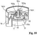
FIG. 1 is a perspective view of a valve device for fuel tank according to one embodiment of this invention.FIG. 2 is a sectional view of the valve device, and specifically illustrates the state in which the fuel level inside the tank has not reached the level of the inflow part provided on the lower end of the valve device.FIG. 3 is a sectional view of the valve device, and specifically illustrates the state in which the fuel level inside the tank reached the level of a cylinder lower end of an inner cylinder part serving as the inflow part provided on the lower end of the valve device.FIG. 4 is a sectional view of the valve device, and specifically illustrates the state (seated state) in which fueling was further performed from the state inFIG. 3 so that the fuel flowed into the case constituting the valve device and the upper float body ascended to close the air flow valve orifice.FIG. 5 is a perspective view illustrating in partial cutaway the lower body constituting the case, and the lower float body is in the descended position.FIG. 6 is a perspective view illustrating in partial cutaway the lower body constituting the case, and the lower float body is in the ascended position.FIG. 7 illustrates the lower body constituting the case viewed from above.FIG. 8 is a perspective view illustrating an example in which a part of the configuration of the lower body and the lower float body is modified.FIG. 9 is a partial sectional perspective view of the modified example inFIG. 8 , and the lower float body is in the descended position.FIG. 10 is a partial sectional perspective view of the modified example inFIG. 8 , wherein the lower float body is in the ascended position.- A typical embodiment of this invention is described below based on
FIGS. 1 to 10 . The valve device for fuel tank according to this embodiment is installed on a fuel tank T of an automobile, motorcycle, or the like, and functions to connect through between the inside and outside of the tank in the open-valve state. - Such valve device typically is installed on an upper part of the fuel tank T, and constitutes a portion of a connection channel air flow channel E) to the fuel tank T. In addition, the valve device according to this embodiment functions to block the connection through between the inside and the outside of the tank by utilizing a rise of the fuel level due to injection of fuel F into the fuel tank T, so that the fuel level inside the filler pipe is raised by a consequent increase of pressure inside the tank and a full-tank state is detected by a sensor in the fueling gun.
- More specifically, in the valve device according to this embodiment, firstly, when the fuel level inside the fuel tank T reaches a prescribed first level fa, a
lower float body 5 to be described is caused to ascend to throttle, so to say, the air flow channel E, the fuel level inside the filler pipe not illustrated is raised by a consequent increase of pressure inside the fuel tank T, and an initial full-tank state is detected by a sensor in the fueling gun. Next, secondly, after fueling is stopped by the detection of this initial full-tank state, the pressure inside the tank decreases by air flow passing through the throttled air flow channel E, the fuel level inside the filler pipe drops, and additional fueling is allowed. Also, thirdly, when the fuel level inside the fuel tank T reaches a prescribed second level fb higher than the first level fa by this additional fueling, an upper float body 3 to be described is caused to ascend and the air flow channel E is closed, the fuel level inside the filler pipe is raised by a consequent increase of pressure inside the fuel tank T, and a final full-tank state is detected by the sensor in the fueling gun. - Such valve device has a
case 1, an upper float body 3, and alower float body 5. - The
case 1 has an airflow valve orifice 10 opening a passage with outside of the tank at an upper part, and has afuel inflow part 11 beneath this air flow valve orifice, and is divided into anupper chamber 13 and alower chamber 14 by apartition 12 formed between the airflow valve orifice 10 and theinflow part 11. - In the illustrated example,
such case 1 is configured with anupper body 15 and alower body 16. Theupper body 15 is configured to have a cylindrical form. The cylinder upper end of theupper body 15 is closed by a ceiling part 15a having a circular airflow valve orifice 10 in the center. On the upper face of the ceiling part 15a, a shortcylindrical part 15b projecting upward from the ceiling part 15a is integrally formed with the ceiling part 15a with the space inside the cylinder connecting through to the airflow valve orifice 10. A sealing 15c is fitted on the outside of the shortcylindrical part 15b. The cylinder lower end of theupper body 15 is open. - Meanwhile, the
lower body 16 is configured to have a cylindrical form with the cylinder upper and lower ends both being open. A dividingwall 160 dividing the space inside thelower body 16 into upper and lower parts is formed between the cylinder upper and lower ends of thelower body 16. A circular through-hole 161a is formed in the center part of the dividingwall 160, and this through-hole 161a serves as a main connect-throughpart 161 to be described. Also, a through-hole 162a serving as an auxiliary connect-throughpart 162 to be described, being smaller than the through-hole 161a, is formed in both side positions surrounding the through-hole 161a. - Also, a disk-
form body 163 having an outer diameter roughly equal to the hole diameter of the through-hole 161a is placed directly above the through-hole 121a of the dividingwall 160, such that the outer edge thereof overlaps on the hole edge of the through-hole 161a in the condition in plan view, and such that a gap is opened in the vertical direction between the lower face of the disk-form body 163 and the upper face of the dividingwall 160. In the illustrated example,bridge pieces 164 spanning between the disk-form body 163 and the dividingwall 160 are provided in four places opening spaces in the direction around the center of the disk-form body 163, such that the disk-form body 163 is supported on the dividingwall 160 as previously mentioned by thesebridge pieces 164 in four places. In the illustrated example, thepartition 12 is constituted bysuch dividing wall 160 and disk-form body 163. - Also, an
insertion part 165 to be described is formed in the center of the disk-form part 163. Theinsertion part 165 is configured with an insertion hole 164a provided in a condition running through the center of the disk-form body 163, and a cylindrical support part 165b projecting upward from the upper face of the disk-form body 163 such that the cylinder lower end is connected through to theinsertion hole 165a. The cylindrical support part 165b is divided into four parts by providing slits spanning between the cylinder upper end and the cylinder lower end in four places opening spaces in the direction around the cylinder shaft, and each divided place functions as anelastic piece 165c. - Also, a plurality of projections, 166, 166, ... is formed on the upper face of the disk-
form body 163, opening roughly equal spaces betweenadjacent projections 166 on an arc of a virtual circle surrounding the cylindrical support part 165b, and the spring lower end of acompression coil spring 4 to be described is combined on the disk-form body 163 such that the array of theseprojections - Also, an
inner cylinder part 167 is placed beneath the dividingwall 160 of thelower body 16. The cylinder upper end of thisinner cylinder part 167 is integrally connected to the lower face of the dividingwall 160 such that the main connect-throughpart 161 is positioned inside the cylinder upper end. Also, the cylinder lower end of theinner cylinder part 167 is positioned on the same level as the cylinder lower end of thelower body 16. - Also, a
cutout part 168 splitting a part of the outer shell of thelower body 16 is formed on the cylinder lower end side of thelower body 16 in a position to become directly beneath the auxiliary connect-throughpart 162. Thiscutout part 168 is open at the cylinder lower end of thelower body 16, and the upper end of thecutout part 168 is positioned above the cylinder lower end of theinner cylinder part 167 and beneath thepartition 12. - In the illustrated example, the
case 1 is constituted with theupper body 15 being fitted from the cylinder lower end side, inside a place on suchlower body 16 above the dividingwall 160. In thecase 1 thus constituted, the cylinder lower end of thelower body 16 and thecutout part 168 function as theinflow part 11. - Also, in the illustrated example,
such case 1 is combined on aflange 2 so as to be installed on the fuel tank T using thisflange 2. Theflange 2 has ahead part 20 and acylindrical connection part 21 projecting downward from thehead part 20. Aconnection tube part 22 projecting to the side is integrally provided on thehead part 20, and thisconnection tube part 22 is connected through with the space inside thecylindrical connection part 21 in the center of thehead part 20. This connect-through part is surrounded by a circumferential raised part 23 on the inside of theflange 2. In the illustrated example, theflange 2 and thecase 1 are integrated by fitting the upper part of theupper case 1 inside thecylindrical connection part 21 of theflange 2 such that the shortcylindrical part 15b of theupper body 15 is inserted inside the circumferential raised part 23 of theflange 2. The space between the shortcylindrical part 15b of theupper body 15 and the circumferential raised part 23 of theflange 2 is sealed air-tightly by the sealing 15c. By this, the inside and outside of the tank are connected through by way of theinflow part 11 of thecase 1, the airflow valve orifice 10, and theconnection tube part 22. Thecase 1 is placed inside the tank by being inserted from outside into an installation hole Ta being opened on the fuel tank T and having a size such that thehead part 20 ofsuch flange 2 does not fit, and is attached to the fuel tank T by welding or otherwise fixing thehead part 20 of theflange 2 on the outer face part of the fuel tank T. - The upper float body 3 is inside the
upper chamber 13 of thecase 1 and ascends by fuel flowing into thecase 1 to be seated in said airflow valve orifice 10. In the state in which fuel has not flowed into theupper chamber 13, the upper float body 3 is in the descended position being supported on the disk-form body 163 constituting thepartition 12 of thelower body 16, and the airflow valve orifice 10 is open (FIGS. 2 and3 ). - In the illustrated example, such upper float body 3 has a float main body 30 having a ceiling part and a cylindrical-form side part, a
seal member 31 for sealing the airflow valve orifice 10, and asupport member 32 for thisseal member 31. Thesupport member 32 is constituted as a disk form in general, having an outwardly projectingcoupling claw 32a on the outer perimeter part and a through-hole 32b in the center part. Apart 30a coupled with, on which is coupled thecoupling claw 32a ofsuch support member 32, is formed on the outer perimeter part of the ceiling part of the float main body 30, and thesupport member 32 is placed on the ceiling part of the float main body 30 in a state in which thecoupling claw 32a is coupled on thispart 30a coupled with. Theseal member 32 is formed in a disk form having an outer diameter sufficient to close the airflow valve orifice 10, and has an insertion-fitting projecting part 31a for insertion-fitting into the through-hole 32b of thesupport member 32 in the center of the lower part, and is combined on thesupport member 32 using this insertion-fitting projecting part 31a so as to be positioned directly beneath the airflow valve orifice 10. - A receiving
hole 33 in which aguide shaft 50 to be described of thelower float body 5 is received is provided on such upper float body 3. This receivinghole 33 is formed inside a recessedplace 30b formed in the center of the lower part of the float main body 30 of the upper float body 3. This recessedplace 30b is formed in a circular pit form. A boss-form part 30c projecting downward from the upper floor of this recessedplace 30b is formed inside this recessedplace 30b. The lower end of the boss-form part 30c is positioned beneath the cylinder lower end of the upper float body 3 such that the cylindrical support part 165b and the array ofprojections place 30b beneath the lower end of this boss-form part 30c during descent of the upper float body 3 (FIGS. 2 and3 ). Also, thecompression coil spring 4 is installed in a compressed state inside this recessedplace 30b such that the boss-form part 30c is received inside. The spring lower end of thisspring 4 contacts the dividingwall 160 of thelower body 16, and the spring upper end contacts the upper floor of the recessedplace 30b, such that a constant upward force is applied to the upper float 3 by thisspring 4. - The
lower float body 5 has an upwardly projectingguide shaft 50, is supported inside thelower chamber 14 of thecase 1 with thisguide shaft 50 being inserted to be movable up and down from the side of thislower chamber 14 inside theinsertion part 165 formed on thepartition 12, and ascends by fuel flowing into thecase 1 to close the main connect-throughpart 161 between thelower chamber 14 and theupper chamber 13 formed on thepartition 12. - In the illustrated example, such
lower float body 5 has a floatmain body 51 received to be movable vertically inside theinner cylinder part 167 of thelower case 1, and theguide shaft 50. The floatmain body 51 is formed in a short cylindrical form, and is received inside theinner cylinder part 167 such that the cylinder shaft thereof is aligned in the vertical direction. The cylinder upper end of this floatmain body 51 is closed, and the cylinder lower end is open. The outer diameter of thelower float body 5 is larger than that of the main connect-throughpart 161 provided on the dividingwall 160 constituting thepartition 12. - The
guide shaft 50 has ahead part 50a on the upper end. Also, the outer diameter of amiddle part 50c between thehead part 50a and abase part 50b is made roughly equal to the inner diameter of the cylinder upper end of the cylindrical support part 165b constituting theinsertion part 165, and the outer diameter of thebase part 50b is made roughly equal to that of thehead part 50a and wider than that of the middle part 500c, and is made roughly equal to the hole diameter of theinsertion hole 165a constituting theinsertion part 165. Also, in this embodiment, thelower float body 5 is supported in a suspended manner on thepartition 12 in a state in which thehead part 50a of theguide shaft 50, being passed through the cylindrical support part 165b through theinsertion hole 165a, is caught on the cylinder upper end of this cylindrical support part 165b. In this caught state, thelower float body 5 is in the most descended position, and thepartition 12 and the cylinder upper end of the float main body are moved apart so that the main connect-throughpart 161 is open (FIG. 2 ). - The air flow between the inside and outside of the tank is assured through the
inflow part 11, the main connect-throughpart 161, the auxiliary connect-throughpart 162, and the airflow valve orifice 10, until the fuel level reaches theinflow part 11 of thecase 1. The air flow through the main connect-throughpart 161 is accomplished through the space between the side face of the floatmain body 51 of thelower float body 5 and the inside face of theinner cylinder part 167, the air flow through the auxiliary connect-throughpart 162 is accomplished through thecutout part 168, and the air flow through the airflow valve orifice 10 is accomplished through the space between the side part of the float main body 30 of the upper float body 3 and the inside face of the upper chamber 13 (FIG. 2 ). When the fuel level reaches the cylinder lower end of theinner cylinder part 167 constituting theinflow part 11 of thecase 1 by fueling (first level fa), the fuel F enters thelower chamber 14 due to a differential pressure between the pressure inside the tank and the pressure inside thecase 1, thelower float body 5 ascends, the main connect-throughpart 161 is closed thereby, the fuel level inside the filler pipe is raised by the pressure increase inside the tank, and an initial full-tank state is detected by a sensor in the fueling gun. Specifically, at this time, the fuel enters theinner cylinder part 167, and thelower float body 5 ascends (FIG. 3 ). When fueling stops upon detection of the initial full-tank state, because thelower float body 5 remains to close the main connect-throughpart 161, the internal pressure inside the tank decreases by air flow, and additional fueling becomes possible. Specifically, additional fueling is allowed by air flow through thecutout part 168 and the auxiliary connect-throughpart 162. When the fuel level rises further by the additional fueling, the fuel enters theupper chamber 13, and the upper float body 3 ascends to be seated in the airflow valve orifice 10. By this, the fuel level inside the filler pipe is raised again by the pressure increase inside the tank, and a final full-tank state is detected by the sensor in the fueling gun. Specifically, when the fuel level reaches the upper end of the cutout part 168 (second level fb), the fuel enters theupper chamber 13 through the auxiliary connect-throughpart 162 by a differential pressure between the pressure inside the tank and the pressure inside the case 1 (FIG. 4 ). When the fuel level drops, first the fuel F flows out from theupper chamber 13, the upper float body 3 descends, and the airflow valve orifice 10 is opened. Next, when the fuel level drops further, thelower float body 5 descends, and the main connect-throughpart 161 is opened. Because thelower float body 5 is supported with theguide shaft 50 being passed through theinsertion part 165 provided on thepartition 12, a gap is created between the side face of thelower float body 5 and the inside face of thelower chamber 14, in the illustrated example, the inside face of theinside cylinder part 167, and contact between the two can be prevented. Also, because the receivinghole 33 for receiving theguide shaft 50 is provided on the upper float body 3, the size in the vertical direction of the valve device configured with the upper float body 3 and thelower float body 5 can be made as small as possible. Specifically, in this embodiment, theguide shaft 50 of thelower float body 5 is received in the receivinghole 33 of the upper float body 3 when the upper float body 3 has not ascended, that is, is in the descended position and thelower float body 5 has ascended (FIG. 3 ). - Also, in this embodiment, the
insertion part 165 provided on thepartition 12 has apart 165d for sliding-contact with theguide shaft 50 at least on an upper end side and on a lower end side thereof. Specifically, no matter what position thelower float body 5 is in, that is, whether it is in the ascended position closing the main connect-throughpart 161 or is in the descended position, thebase part 50b of theguide shaft 50 is slid contacting with theinsertion hole 165a, and themiddle part 50c of theguide shaft 50 is slid contacting inside the cylinder upper end of the cylindrical support part 165b. By this, in this embodiment, the vertical movement of thelower float body 5 can be made smooth without tilting by the support on at least two points vertically. - Also, in this embodiment, a
coupling part 165e for allowing passage from beneath thehead part 50a of theguide shaft 50 by elastic deformation is formed on an upper end of theinsertion part 165. In the illustrated example, the cylindrical support part 165b is configured with fourelastic pieces 165c, ..., 165c, and when theguide shaft 50 is passed through theinsertion part 165 from beneath through theinsertion hole 165a, the fourelastic pieces 165c, ..., 165c first flex outward and are then coupled with thishead part 50a. That is, in the illustrated example, the upper ends of suchelastic pieces 165c function as thecoupling part 165e. By this, in this embodiment, thelower float body 5 can be combined easily and appropriately onto thepartition 12, and can be supported in a suspended manner on thispartition 12. FIGS. 8 to 10 illustrate an example in which a part of the configuration of thelower body 16 and thelower float body 5 constituting the valve device described above is modified.- In this modified example, at least a portion of the
coupling part 165e of theinsertion part 165 is configured with anarm piece 165g projecting sideways from an upper end of an upwardly projectingbase part piece 165f so that the projecting end is coupled with thehead part 50a. Also, a place on the upper part of thelower float body 5 contacting with thepartition 12 at least when ascending is covered by an elastic material. - In this modified example, two
elastic pieces 165c in opposite positions of the fourelastic pieces 165c constituting the cylindrical support part 165b constituting theinsertion part 165 are replaced with thebase part piece 165f and the arm piece 155g. Thebase part piece 165f is positioned further outside from theelastic piece 165c, and a space is formed between thebase part piece 165f and theguide shaft 50. Thearm piece 165g projects inward from the upper end of thisbase part piece 165f and is positioned in a position where the projecting end thereof is coupled with thehead part 50a. By this, in this modified example, the collision of thehead part 50a being contacted from above with thearm piece 165g when thelower float body 5 in the ascended position descends can be absorbed by elastic deformation of thearm piece 165g, and production of a sound of collision in this case can be prevented (FIG. 9 ). - Also, in this modified example, the closed cylinder upper end of the float
main body 51 is covered by a disk-formelastic material 52 having an outer diameter somewhat smaller than the outer diameter of thelower float body 5. A through-hole 52a is formed in the center of theelastic seal material 52, and theelastic seal material 52 is affixed to the cylinder upper end of the floatmain body 51 with theguide shaft 50 passing through this through-hole 52a. By this, in this modified example, the collision of the contact of thelower float body 5 to thepartition 12 when thelower float body 5 in the descended position (FIG. 9 ) ascends can be absorbed by theelastic sealing material 52 as the elastic material, and production of a sound of collision in this case also can be prevented (FIG. 10 ).
Claims (4)
- A valve device for a fuel tank (T), comprising:a case (1) having an air flow valve orifice (10) communicated with outside of the tank at an upper part thereof, and a fuel inflow part (11) below the air flow valve orifice (10), said case (1) being divided into an upper chamber (13) and a lower chamber (14) by a partition (12) formed between the air flow valve orifice (10) and the inflow part (11);an upper float body (3) disposed inside the upper chamber (13) of the case (1), and ascending by fuel flowing into the case (1) to be seated in said air flow valve orifice (10); anda lower float body (5) having an upwardly projecting guide shaft (50), being supported inside the lower chamber (14) of the case (1) with the guide shaft (50) being inserted to be movable vertically inside an insertion part (165) formed on said partition (12), and ascending by the fuel flowing into the case (1) to close a main connect-through part (161) between the lower chamber (14) and the upper chamber (13), formed on said partition (12),wherein said upper float body (3) has a receiving hole (33) to receive the guide shaft (50) of the lower float body (5), wherein said guide shaft (50) comprises a head part (50a) on an upper end thereof, and a coupling part (165e) for passing from below the head part (50a) is formed on an upper end of the insertion part (165) by elastic deformation,characterized in thatat least a portion of the coupling part (165e) of the insertion part (165) comprises an arm piece (165g) projecting sideways from an upper end of an upwardly projecting base part piece (165f) to couple a projecting end with the head part (50a),wherein a disk-form body (163) having an outer diameter roughly equal to a hole diameter of a through-hole (161a) is placed directly above a through-hole (121a) of a dividing wall (160), such that the outer edge thereof overlaps on the hole edge of the through-hole (161a) and such that a gap is opened in the vertical direction between the lower face of the disk-form body (163) and the upper face of the dividing wall (160),wherein bridge pieces (164) spanning between the disk-form body (163) and the dividing wall (160) are provided in four places opening spaces in the direction around the center of the disk-form body (163), such that the disk-form body (163) is supported on the dividing wall (160) by these bridge pieces (164) in four places.
- A valve device for fuel tank (T) according to claim 1, wherein a portion on an upper part of the lower float body (5) contacting with the partition (12) at least when ascending is covered by an elastic material.
- A valve device for fuel tank (T) according to claim 1 or 2, wherein the insertion part (165) comprises a part to slidingly contact the guide shaft (50) at least on an upper end side and on a lower end side thereof.
- A valve device for fuel tank (T) according to claim 1, wherein the guide shaft (50) of the lower float body (5) is received in the receiving hole (33) of the upper float body (3) at least when the upper float body (3) has not ascended and the lower float body (5) has ascended.
Applications Claiming Priority (2)
| Application Number | Priority Date | Filing Date | Title |
|---|---|---|---|
| JP2009286400AJP5437784B2 (en) | 2009-12-17 | 2009-12-17 | Valve device for fuel tank |
| PCT/JP2010/072149WO2011074478A1 (en) | 2009-12-17 | 2010-12-09 | Fuel tank valve device |
Publications (3)
| Publication Number | Publication Date |
|---|---|
| EP2514621A1 EP2514621A1 (en) | 2012-10-24 |
| EP2514621A4 EP2514621A4 (en) | 2014-05-14 |
| EP2514621B1true EP2514621B1 (en) | 2019-04-10 |
Family
ID=44167234
Family Applications (1)
| Application Number | Title | Priority Date | Filing Date |
|---|---|---|---|
| EP10837506.4AActiveEP2514621B1 (en) | 2009-12-17 | 2010-12-09 | Fuel tank valve device |
Country Status (6)
| Country | Link |
|---|---|
| US (1) | US9783046B2 (en) |
| EP (1) | EP2514621B1 (en) |
| JP (1) | JP5437784B2 (en) |
| KR (1) | KR101409052B1 (en) |
| CN (1) | CN102656041B (en) |
| WO (1) | WO2011074478A1 (en) |
Families Citing this family (14)
| Publication number | Priority date | Publication date | Assignee | Title |
|---|---|---|---|---|
| JP5767947B2 (en)* | 2011-11-11 | 2015-08-26 | 株式会社ニフコ | Fuel tank exhaust valve device |
| JP5874601B2 (en)* | 2012-10-31 | 2016-03-02 | 豊田合成株式会社 | Fuel shut-off valve |
| CN103321798A (en)* | 2013-06-25 | 2013-09-25 | 苏州圆能动力科技有限公司 | Topping-preventive valve with separating barrel |
| CN103470831B (en)* | 2013-09-23 | 2015-11-18 | 孙达立 | A kind of overflow cutting valve |
| JP6203205B2 (en) | 2014-05-09 | 2017-09-27 | 株式会社ニフコ | Valve device |
| GB2544004B (en) | 2014-08-25 | 2020-05-06 | Piolax Inc | Valve case mounting structure |
| JP6488121B2 (en)* | 2014-12-18 | 2019-03-20 | 株式会社パイオラックス | Valve device for fuel tank |
| JP6520639B2 (en)* | 2015-10-22 | 2019-05-29 | 京三電機株式会社 | Fuel tank vent control valve |
| JP2017202804A (en)* | 2016-05-13 | 2017-11-16 | 京三電機株式会社 | Float valve for fuel tank and manufacturing method of the same |
| JP2020016210A (en)* | 2018-07-27 | 2020-01-30 | 株式会社ニフコ | Valve device for fuel tank |
| JP6886434B2 (en)* | 2018-07-27 | 2021-06-16 | 株式会社ニフコ | Fuel tank valve gear |
| DE102019104333A1 (en)* | 2019-02-20 | 2020-08-20 | Röchling Automotive SE & Co. KG | Vehicle liquid tank with integrated float valve |
| JP7138610B2 (en)* | 2019-10-10 | 2022-09-16 | 株式会社ニフコ | Fuel tank valve gear |
| JP7690381B2 (en)* | 2021-11-09 | 2025-06-10 | 株式会社パイオラックス | Full tank control valve |
Family Cites Families (14)
| Publication number | Priority date | Publication date | Assignee | Title |
|---|---|---|---|---|
| JPH04356229A (en)* | 1991-05-31 | 1992-12-09 | Nissan Motor Co Ltd | Vaporized fuel processing apparatus for fuel tank |
| JPH06156093A (en)* | 1992-11-24 | 1994-06-03 | Aisan Ind Co Ltd | Fuel cutoff valve with float |
| JP3284746B2 (en) | 1994-04-28 | 2002-05-20 | 豊田合成株式会社 | Float valve for fuel tank |
| US5535772A (en)* | 1995-05-01 | 1996-07-16 | Stant Manufacturing Inc. | Tank venting control system |
| JP3994273B2 (en)* | 2002-07-15 | 2007-10-17 | 株式会社ニフコ | Fuel tank level detection valve |
| JP2004293325A (en) | 2003-03-25 | 2004-10-21 | Toyoda Gosei Co Ltd | Fuel shut off valve |
| JP2006097178A (en) | 2004-09-29 | 2006-04-13 | Toray Ind Inc | Conjugate fiber |
| JP4415888B2 (en) | 2005-03-22 | 2010-02-17 | 豊田合成株式会社 | Fuel shut-off valve |
| JP4297883B2 (en)* | 2005-04-07 | 2009-07-15 | 株式会社ニフコ | Fuel spill prevention valve device |
| JP2007253778A (en)* | 2006-03-23 | 2007-10-04 | Toyoda Gosei Co Ltd | Fuel shut-off valve |
| JP2008248913A (en)* | 2007-03-29 | 2008-10-16 | Toyoda Gosei Co Ltd | Fuel shut-off valve |
| JP5285888B2 (en)* | 2007-10-02 | 2013-09-11 | 株式会社ニフコ | Valve device |
| JP2009286400A (en) | 2008-05-27 | 2009-12-10 | Fuji Seal International Inc | Package of toilet detergent elution container |
| JP5786788B2 (en)* | 2011-09-26 | 2015-09-30 | 京三電機株式会社 | Full tank control valve device |
- 2009
- 2009-12-17JPJP2009286400Apatent/JP5437784B2/enactiveActive
- 2010
- 2010-12-09EPEP10837506.4Apatent/EP2514621B1/enactiveActive
- 2010-12-09CNCN201080056718.2Apatent/CN102656041B/enactiveActive
- 2010-12-09KRKR1020127016709Apatent/KR101409052B1/enactiveActive
- 2010-12-09WOPCT/JP2010/072149patent/WO2011074478A1/enactiveApplication Filing
- 2010-12-09USUS13/514,486patent/US9783046B2/enactiveActive
Non-Patent Citations (1)
| Title |
|---|
| None* |
Also Published As
| Publication number | Publication date |
|---|---|
| US20160243932A1 (en) | 2016-08-25 |
| CN102656041A (en) | 2012-09-05 |
| WO2011074478A1 (en) | 2011-06-23 |
| KR101409052B1 (en) | 2014-06-18 |
| CN102656041B (en) | 2016-03-30 |
| JP5437784B2 (en) | 2014-03-12 |
| EP2514621A4 (en) | 2014-05-14 |
| KR20120089762A (en) | 2012-08-13 |
| EP2514621A1 (en) | 2012-10-24 |
| JP2011126414A (en) | 2011-06-30 |
| US9783046B2 (en) | 2017-10-10 |
Similar Documents
| Publication | Publication Date | Title |
|---|---|---|
| EP2514621B1 (en) | Fuel tank valve device | |
| US5678590A (en) | Fuel cutoff valve | |
| JP5242440B2 (en) | Fuel tank valve device and fuel tank supercharging prevention device | |
| CN102713233B (en) | Valve device for fuel tank | |
| US8100153B2 (en) | Float valve apparatus | |
| US20150034174A1 (en) | Valve device for fuel tank | |
| US10279679B2 (en) | Valve device | |
| US6901943B2 (en) | Apparatus for inhibiting fuels from flowing out of fuel tanks | |
| US10967734B2 (en) | Valve device for fuel tank | |
| CN213687105U (en) | Humidifier with detachable bivalve | |
| JP2006144756A (en) | Fuel tank pump module structure | |
| US6779545B2 (en) | Pressure control valve for fuel tank | |
| JP2011046369A (en) | Fuel shutting-off valve | |
| WO2022158489A1 (en) | Valve device | |
| JP4207875B2 (en) | Fuel shut-off valve | |
| JPH07280117A (en) | Float valve for fuel tank | |
| JPH0327014Y2 (en) | ||
| KR101964330B1 (en) | Leakage detection valve | |
| JPH0867155A (en) | Fluid cutoff valve | |
| JP2011016478A (en) | Fuel cut-off valve | |
| JP5065074B2 (en) | Valve device for fuel tank | |
| JP2007146794A (en) | Fuel shutoff valve | |
| JP2006142996A (en) | Valve for fuel tank | |
| JP2011016487A (en) | Fuel cut-off valve |
Legal Events
| Date | Code | Title | Description |
|---|---|---|---|
| PUAI | Public reference made under article 153(3) epc to a published international application that has entered the european phase | Free format text:ORIGINAL CODE: 0009012 | |
| 17P | Request for examination filed | Effective date:20120614 | |
| AK | Designated contracting states | Kind code of ref document:A1 Designated state(s):AL AT BE BG CH CY CZ DE DK EE ES FI FR GB GR HR HU IE IS IT LI LT LU LV MC MK MT NL NO PL PT RO RS SE SI SK SM TR | |
| DAX | Request for extension of the european patent (deleted) | ||
| A4 | Supplementary search report drawn up and despatched | Effective date:20140414 | |
| RIC1 | Information provided on ipc code assigned before grant | Ipc:F02M 37/00 20060101ALI20140408BHEP Ipc:B60K 15/01 20060101AFI20140408BHEP Ipc:F16K 31/18 20060101ALI20140408BHEP Ipc:F16K 24/00 20060101ALI20140408BHEP | |
| STAA | Information on the status of an ep patent application or granted ep patent | Free format text:STATUS: EXAMINATION IS IN PROGRESS | |
| 17Q | First examination report despatched | Effective date:20170317 | |
| GRAP | Despatch of communication of intention to grant a patent | Free format text:ORIGINAL CODE: EPIDOSNIGR1 | |
| STAA | Information on the status of an ep patent application or granted ep patent | Free format text:STATUS: GRANT OF PATENT IS INTENDED | |
| INTG | Intention to grant announced | Effective date:20181127 | |
| GRAS | Grant fee paid | Free format text:ORIGINAL CODE: EPIDOSNIGR3 | |
| GRAA | (expected) grant | Free format text:ORIGINAL CODE: 0009210 | |
| STAA | Information on the status of an ep patent application or granted ep patent | Free format text:STATUS: THE PATENT HAS BEEN GRANTED | |
| RAP1 | Party data changed (applicant data changed or rights of an application transferred) | Owner name:NIFCO INC. | |
| AK | Designated contracting states | Kind code of ref document:B1 Designated state(s):AL AT BE BG CH CY CZ DE DK EE ES FI FR GB GR HR HU IE IS IT LI LT LU LV MC MK MT NL NO PL PT RO RS SE SI SK SM TR | |
| REG | Reference to a national code | Ref country code:GB Ref legal event code:FG4D | |
| REG | Reference to a national code | Ref country code:CH Ref legal event code:EP Ref country code:AT Ref legal event code:REF Ref document number:1118168 Country of ref document:AT Kind code of ref document:T Effective date:20190415 | |
| REG | Reference to a national code | Ref country code:IE Ref legal event code:FG4D | |
| REG | Reference to a national code | Ref country code:DE Ref legal event code:R096 Ref document number:602010058214 Country of ref document:DE | |
| REG | Reference to a national code | Ref country code:NL Ref legal event code:MP Effective date:20190410 | |
| REG | Reference to a national code | Ref country code:LT Ref legal event code:MG4D | |
| REG | Reference to a national code | Ref country code:AT Ref legal event code:MK05 Ref document number:1118168 Country of ref document:AT Kind code of ref document:T Effective date:20190410 | |
| PG25 | Lapsed in a contracting state [announced via postgrant information from national office to epo] | Ref country code:NL Free format text:LAPSE BECAUSE OF FAILURE TO SUBMIT A TRANSLATION OF THE DESCRIPTION OR TO PAY THE FEE WITHIN THE PRESCRIBED TIME-LIMIT Effective date:20190410 | |
| PG25 | Lapsed in a contracting state [announced via postgrant information from national office to epo] | Ref country code:NO Free format text:LAPSE BECAUSE OF FAILURE TO SUBMIT A TRANSLATION OF THE DESCRIPTION OR TO PAY THE FEE WITHIN THE PRESCRIBED TIME-LIMIT Effective date:20190710 Ref country code:LT Free format text:LAPSE BECAUSE OF FAILURE TO SUBMIT A TRANSLATION OF THE DESCRIPTION OR TO PAY THE FEE WITHIN THE PRESCRIBED TIME-LIMIT Effective date:20190410 Ref country code:SE Free format text:LAPSE BECAUSE OF FAILURE TO SUBMIT A TRANSLATION OF THE DESCRIPTION OR TO PAY THE FEE WITHIN THE PRESCRIBED TIME-LIMIT Effective date:20190410 Ref country code:ES Free format text:LAPSE BECAUSE OF FAILURE TO SUBMIT A TRANSLATION OF THE DESCRIPTION OR TO PAY THE FEE WITHIN THE PRESCRIBED TIME-LIMIT Effective date:20190410 Ref country code:HR Free format text:LAPSE BECAUSE OF FAILURE TO SUBMIT A TRANSLATION OF THE DESCRIPTION OR TO PAY THE FEE WITHIN THE PRESCRIBED TIME-LIMIT Effective date:20190410 Ref country code:PT Free format text:LAPSE BECAUSE OF FAILURE TO SUBMIT A TRANSLATION OF THE DESCRIPTION OR TO PAY THE FEE WITHIN THE PRESCRIBED TIME-LIMIT Effective date:20190910 Ref country code:AL Free format text:LAPSE BECAUSE OF FAILURE TO SUBMIT A TRANSLATION OF THE DESCRIPTION OR TO PAY THE FEE WITHIN THE PRESCRIBED TIME-LIMIT Effective date:20190410 Ref country code:FI Free format text:LAPSE BECAUSE OF FAILURE TO SUBMIT A TRANSLATION OF THE DESCRIPTION OR TO PAY THE FEE WITHIN THE PRESCRIBED TIME-LIMIT Effective date:20190410 | |
| PG25 | Lapsed in a contracting state [announced via postgrant information from national office to epo] | Ref country code:LV Free format text:LAPSE BECAUSE OF FAILURE TO SUBMIT A TRANSLATION OF THE DESCRIPTION OR TO PAY THE FEE WITHIN THE PRESCRIBED TIME-LIMIT Effective date:20190410 Ref country code:GR Free format text:LAPSE BECAUSE OF FAILURE TO SUBMIT A TRANSLATION OF THE DESCRIPTION OR TO PAY THE FEE WITHIN THE PRESCRIBED TIME-LIMIT Effective date:20190711 Ref country code:PL Free format text:LAPSE BECAUSE OF FAILURE TO SUBMIT A TRANSLATION OF THE DESCRIPTION OR TO PAY THE FEE WITHIN THE PRESCRIBED TIME-LIMIT Effective date:20190410 Ref country code:RS Free format text:LAPSE BECAUSE OF FAILURE TO SUBMIT A TRANSLATION OF THE DESCRIPTION OR TO PAY THE FEE WITHIN THE PRESCRIBED TIME-LIMIT Effective date:20190410 Ref country code:BG Free format text:LAPSE BECAUSE OF FAILURE TO SUBMIT A TRANSLATION OF THE DESCRIPTION OR TO PAY THE FEE WITHIN THE PRESCRIBED TIME-LIMIT Effective date:20190710 | |
| PG25 | Lapsed in a contracting state [announced via postgrant information from national office to epo] | Ref country code:AT Free format text:LAPSE BECAUSE OF FAILURE TO SUBMIT A TRANSLATION OF THE DESCRIPTION OR TO PAY THE FEE WITHIN THE PRESCRIBED TIME-LIMIT Effective date:20190410 Ref country code:IS Free format text:LAPSE BECAUSE OF FAILURE TO SUBMIT A TRANSLATION OF THE DESCRIPTION OR TO PAY THE FEE WITHIN THE PRESCRIBED TIME-LIMIT Effective date:20190810 | |
| REG | Reference to a national code | Ref country code:DE Ref legal event code:R097 Ref document number:602010058214 Country of ref document:DE | |
| PG25 | Lapsed in a contracting state [announced via postgrant information from national office to epo] | Ref country code:RO Free format text:LAPSE BECAUSE OF FAILURE TO SUBMIT A TRANSLATION OF THE DESCRIPTION OR TO PAY THE FEE WITHIN THE PRESCRIBED TIME-LIMIT Effective date:20190410 Ref country code:CZ Free format text:LAPSE BECAUSE OF FAILURE TO SUBMIT A TRANSLATION OF THE DESCRIPTION OR TO PAY THE FEE WITHIN THE PRESCRIBED TIME-LIMIT Effective date:20190410 Ref country code:SK Free format text:LAPSE BECAUSE OF FAILURE TO SUBMIT A TRANSLATION OF THE DESCRIPTION OR TO PAY THE FEE WITHIN THE PRESCRIBED TIME-LIMIT Effective date:20190410 Ref country code:EE Free format text:LAPSE BECAUSE OF FAILURE TO SUBMIT A TRANSLATION OF THE DESCRIPTION OR TO PAY THE FEE WITHIN THE PRESCRIBED TIME-LIMIT Effective date:20190410 Ref country code:DK Free format text:LAPSE BECAUSE OF FAILURE TO SUBMIT A TRANSLATION OF THE DESCRIPTION OR TO PAY THE FEE WITHIN THE PRESCRIBED TIME-LIMIT Effective date:20190410 | |
| PLBE | No opposition filed within time limit | Free format text:ORIGINAL CODE: 0009261 | |
| STAA | Information on the status of an ep patent application or granted ep patent | Free format text:STATUS: NO OPPOSITION FILED WITHIN TIME LIMIT | |
| PG25 | Lapsed in a contracting state [announced via postgrant information from national office to epo] | Ref country code:IT Free format text:LAPSE BECAUSE OF FAILURE TO SUBMIT A TRANSLATION OF THE DESCRIPTION OR TO PAY THE FEE WITHIN THE PRESCRIBED TIME-LIMIT Effective date:20190410 Ref country code:SM Free format text:LAPSE BECAUSE OF FAILURE TO SUBMIT A TRANSLATION OF THE DESCRIPTION OR TO PAY THE FEE WITHIN THE PRESCRIBED TIME-LIMIT Effective date:20190410 | |
| 26N | No opposition filed | Effective date:20200113 | |
| PG25 | Lapsed in a contracting state [announced via postgrant information from national office to epo] | Ref country code:TR Free format text:LAPSE BECAUSE OF FAILURE TO SUBMIT A TRANSLATION OF THE DESCRIPTION OR TO PAY THE FEE WITHIN THE PRESCRIBED TIME-LIMIT Effective date:20190410 | |
| PG25 | Lapsed in a contracting state [announced via postgrant information from national office to epo] | Ref country code:SI Free format text:LAPSE BECAUSE OF FAILURE TO SUBMIT A TRANSLATION OF THE DESCRIPTION OR TO PAY THE FEE WITHIN THE PRESCRIBED TIME-LIMIT Effective date:20190410 | |
| REG | Reference to a national code | Ref country code:CH Ref legal event code:PL | |
| REG | Reference to a national code | Ref country code:BE Ref legal event code:MM Effective date:20191231 | |
| PG25 | Lapsed in a contracting state [announced via postgrant information from national office to epo] | Ref country code:MC Free format text:LAPSE BECAUSE OF FAILURE TO SUBMIT A TRANSLATION OF THE DESCRIPTION OR TO PAY THE FEE WITHIN THE PRESCRIBED TIME-LIMIT Effective date:20190410 | |
| PG25 | Lapsed in a contracting state [announced via postgrant information from national office to epo] | Ref country code:IE Free format text:LAPSE BECAUSE OF NON-PAYMENT OF DUE FEES Effective date:20191209 Ref country code:LU Free format text:LAPSE BECAUSE OF NON-PAYMENT OF DUE FEES Effective date:20191209 | |
| PG25 | Lapsed in a contracting state [announced via postgrant information from national office to epo] | Ref country code:LI Free format text:LAPSE BECAUSE OF NON-PAYMENT OF DUE FEES Effective date:20191231 Ref country code:CH Free format text:LAPSE BECAUSE OF NON-PAYMENT OF DUE FEES Effective date:20191231 Ref country code:BE Free format text:LAPSE BECAUSE OF NON-PAYMENT OF DUE FEES Effective date:20191231 | |
| PG25 | Lapsed in a contracting state [announced via postgrant information from national office to epo] | Ref country code:CY Free format text:LAPSE BECAUSE OF FAILURE TO SUBMIT A TRANSLATION OF THE DESCRIPTION OR TO PAY THE FEE WITHIN THE PRESCRIBED TIME-LIMIT Effective date:20190410 | |
| PG25 | Lapsed in a contracting state [announced via postgrant information from national office to epo] | Ref country code:MT Free format text:LAPSE BECAUSE OF FAILURE TO SUBMIT A TRANSLATION OF THE DESCRIPTION OR TO PAY THE FEE WITHIN THE PRESCRIBED TIME-LIMIT Effective date:20190410 Ref country code:HU Free format text:LAPSE BECAUSE OF FAILURE TO SUBMIT A TRANSLATION OF THE DESCRIPTION OR TO PAY THE FEE WITHIN THE PRESCRIBED TIME-LIMIT; INVALID AB INITIO Effective date:20101209 | |
| PGFP | Annual fee paid to national office [announced via postgrant information from national office to epo] | Ref country code:DE Payment date:20211102 Year of fee payment:12 | |
| PG25 | Lapsed in a contracting state [announced via postgrant information from national office to epo] | Ref country code:MK Free format text:LAPSE BECAUSE OF FAILURE TO SUBMIT A TRANSLATION OF THE DESCRIPTION OR TO PAY THE FEE WITHIN THE PRESCRIBED TIME-LIMIT Effective date:20190410 | |
| REG | Reference to a national code | Ref country code:DE Ref legal event code:R119 Ref document number:602010058214 Country of ref document:DE | |
| PG25 | Lapsed in a contracting state [announced via postgrant information from national office to epo] | Ref country code:DE Free format text:LAPSE BECAUSE OF NON-PAYMENT OF DUE FEES Effective date:20230701 | |
| PGFP | Annual fee paid to national office [announced via postgrant information from national office to epo] | Ref country code:GB Payment date:20241104 Year of fee payment:15 | |
| PGFP | Annual fee paid to national office [announced via postgrant information from national office to epo] | Ref country code:FR Payment date:20241111 Year of fee payment:15 |