EP2514478B1 - Flexible plastic hose and method for manufacturing same - Google Patents
Flexible plastic hose and method for manufacturing sameDownload PDFInfo
- Publication number
- EP2514478B1 EP2514478B1EP11163335.0AEP11163335AEP2514478B1EP 2514478 B1EP2514478 B1EP 2514478B1EP 11163335 AEP11163335 AEP 11163335AEP 2514478 B1EP2514478 B1EP 2514478B1
- Authority
- EP
- European Patent Office
- Prior art keywords
- hose
- hose body
- stress relief
- flexible plastic
- relief element
- Prior art date
- Legal status (The legal status is an assumption and is not a legal conclusion. Google has not performed a legal analysis and makes no representation as to the accuracy of the status listed.)
- Active
Links
Images


Classifications
- F—MECHANICAL ENGINEERING; LIGHTING; HEATING; WEAPONS; BLASTING
- F16—ENGINEERING ELEMENTS AND UNITS; GENERAL MEASURES FOR PRODUCING AND MAINTAINING EFFECTIVE FUNCTIONING OF MACHINES OR INSTALLATIONS; THERMAL INSULATION IN GENERAL
- F16L—PIPES; JOINTS OR FITTINGS FOR PIPES; SUPPORTS FOR PIPES, CABLES OR PROTECTIVE TUBING; MEANS FOR THERMAL INSULATION IN GENERAL
- F16L11/00—Hoses, i.e. flexible pipes
- F16L11/04—Hoses, i.e. flexible pipes made of rubber or flexible plastics
- F16L11/11—Hoses, i.e. flexible pipes made of rubber or flexible plastics with corrugated wall
- F16L11/118—Hoses, i.e. flexible pipes made of rubber or flexible plastics with corrugated wall having arrangements for particular purposes, e.g. electrically conducting
- F16L11/1185—Hoses, i.e. flexible pipes made of rubber or flexible plastics with corrugated wall having arrangements for particular purposes, e.g. electrically conducting electrically conducting
- A—HUMAN NECESSITIES
- A61—MEDICAL OR VETERINARY SCIENCE; HYGIENE
- A61M—DEVICES FOR INTRODUCING MEDIA INTO, OR ONTO, THE BODY; DEVICES FOR TRANSDUCING BODY MEDIA OR FOR TAKING MEDIA FROM THE BODY; DEVICES FOR PRODUCING OR ENDING SLEEP OR STUPOR
- A61M16/00—Devices for influencing the respiratory system of patients by gas treatment, e.g. ventilators; Tracheal tubes
- A61M16/08—Bellows; Connecting tubes ; Water traps; Patient circuits
- A61M16/0875—Connecting tubes
- A—HUMAN NECESSITIES
- A61—MEDICAL OR VETERINARY SCIENCE; HYGIENE
- A61M—DEVICES FOR INTRODUCING MEDIA INTO, OR ONTO, THE BODY; DEVICES FOR TRANSDUCING BODY MEDIA OR FOR TAKING MEDIA FROM THE BODY; DEVICES FOR PRODUCING OR ENDING SLEEP OR STUPOR
- A61M39/00—Tubes, tube connectors, tube couplings, valves, access sites or the like, specially adapted for medical use
- A61M39/10—Tube connectors; Tube couplings
- A61M39/12—Tube connectors; Tube couplings for joining a flexible tube to a rigid attachment
- F—MECHANICAL ENGINEERING; LIGHTING; HEATING; WEAPONS; BLASTING
- F16—ENGINEERING ELEMENTS AND UNITS; GENERAL MEASURES FOR PRODUCING AND MAINTAINING EFFECTIVE FUNCTIONING OF MACHINES OR INSTALLATIONS; THERMAL INSULATION IN GENERAL
- F16L—PIPES; JOINTS OR FITTINGS FOR PIPES; SUPPORTS FOR PIPES, CABLES OR PROTECTIVE TUBING; MEANS FOR THERMAL INSULATION IN GENERAL
- F16L11/00—Hoses, i.e. flexible pipes
- F16L11/04—Hoses, i.e. flexible pipes made of rubber or flexible plastics
- F16L11/11—Hoses, i.e. flexible pipes made of rubber or flexible plastics with corrugated wall
- F16L11/112—Hoses, i.e. flexible pipes made of rubber or flexible plastics with corrugated wall having reinforcements embedded in the wall
- F—MECHANICAL ENGINEERING; LIGHTING; HEATING; WEAPONS; BLASTING
- F16—ENGINEERING ELEMENTS AND UNITS; GENERAL MEASURES FOR PRODUCING AND MAINTAINING EFFECTIVE FUNCTIONING OF MACHINES OR INSTALLATIONS; THERMAL INSULATION IN GENERAL
- F16L—PIPES; JOINTS OR FITTINGS FOR PIPES; SUPPORTS FOR PIPES, CABLES OR PROTECTIVE TUBING; MEANS FOR THERMAL INSULATION IN GENERAL
- F16L33/00—Arrangements for connecting hoses to rigid members; Rigid hose-connectors, i.e. single members engaging both hoses
- F16L33/24—Arrangements for connecting hoses to rigid members; Rigid hose-connectors, i.e. single members engaging both hoses with parts screwed directly on or into the hose
- F—MECHANICAL ENGINEERING; LIGHTING; HEATING; WEAPONS; BLASTING
- F16—ENGINEERING ELEMENTS AND UNITS; GENERAL MEASURES FOR PRODUCING AND MAINTAINING EFFECTIVE FUNCTIONING OF MACHINES OR INSTALLATIONS; THERMAL INSULATION IN GENERAL
- F16L—PIPES; JOINTS OR FITTINGS FOR PIPES; SUPPORTS FOR PIPES, CABLES OR PROTECTIVE TUBING; MEANS FOR THERMAL INSULATION IN GENERAL
- F16L33/00—Arrangements for connecting hoses to rigid members; Rigid hose-connectors, i.e. single members engaging both hoses
- F16L33/34—Arrangements for connecting hoses to rigid members; Rigid hose-connectors, i.e. single members engaging both hoses with bonding obtained by vulcanisation, gluing, melting, or the like
- F—MECHANICAL ENGINEERING; LIGHTING; HEATING; WEAPONS; BLASTING
- F16—ENGINEERING ELEMENTS AND UNITS; GENERAL MEASURES FOR PRODUCING AND MAINTAINING EFFECTIVE FUNCTIONING OF MACHINES OR INSTALLATIONS; THERMAL INSULATION IN GENERAL
- F16L—PIPES; JOINTS OR FITTINGS FOR PIPES; SUPPORTS FOR PIPES, CABLES OR PROTECTIVE TUBING; MEANS FOR THERMAL INSULATION IN GENERAL
- F16L35/00—Special arrangements used in connection with end fittings of hoses, e.g. safety or protecting devices
- A—HUMAN NECESSITIES
- A61—MEDICAL OR VETERINARY SCIENCE; HYGIENE
- A61M—DEVICES FOR INTRODUCING MEDIA INTO, OR ONTO, THE BODY; DEVICES FOR TRANSDUCING BODY MEDIA OR FOR TAKING MEDIA FROM THE BODY; DEVICES FOR PRODUCING OR ENDING SLEEP OR STUPOR
- A61M16/00—Devices for influencing the respiratory system of patients by gas treatment, e.g. ventilators; Tracheal tubes
- A61M16/08—Bellows; Connecting tubes ; Water traps; Patient circuits
- A61M16/0816—Joints or connectors
- A—HUMAN NECESSITIES
- A61—MEDICAL OR VETERINARY SCIENCE; HYGIENE
- A61M—DEVICES FOR INTRODUCING MEDIA INTO, OR ONTO, THE BODY; DEVICES FOR TRANSDUCING BODY MEDIA OR FOR TAKING MEDIA FROM THE BODY; DEVICES FOR PRODUCING OR ENDING SLEEP OR STUPOR
- A61M16/00—Devices for influencing the respiratory system of patients by gas treatment, e.g. ventilators; Tracheal tubes
- A61M16/10—Preparation of respiratory gases or vapours
- A61M16/1075—Preparation of respiratory gases or vapours by influencing the temperature
- A61M16/1095—Preparation of respiratory gases or vapours by influencing the temperature in the connecting tubes
- A—HUMAN NECESSITIES
- A61—MEDICAL OR VETERINARY SCIENCE; HYGIENE
- A61M—DEVICES FOR INTRODUCING MEDIA INTO, OR ONTO, THE BODY; DEVICES FOR TRANSDUCING BODY MEDIA OR FOR TAKING MEDIA FROM THE BODY; DEVICES FOR PRODUCING OR ENDING SLEEP OR STUPOR
- A61M16/00—Devices for influencing the respiratory system of patients by gas treatment, e.g. ventilators; Tracheal tubes
- A61M16/10—Preparation of respiratory gases or vapours
- A61M16/14—Preparation of respiratory gases or vapours by mixing different fluids, one of them being in a liquid phase
- A61M16/16—Devices to humidify the respiration air
- A61M16/161—Devices to humidify the respiration air with means for measuring the humidity
- A—HUMAN NECESSITIES
- A61—MEDICAL OR VETERINARY SCIENCE; HYGIENE
- A61M—DEVICES FOR INTRODUCING MEDIA INTO, OR ONTO, THE BODY; DEVICES FOR TRANSDUCING BODY MEDIA OR FOR TAKING MEDIA FROM THE BODY; DEVICES FOR PRODUCING OR ENDING SLEEP OR STUPOR
- A61M16/00—Devices for influencing the respiratory system of patients by gas treatment, e.g. ventilators; Tracheal tubes
- A61M16/10—Preparation of respiratory gases or vapours
- A61M16/1005—Preparation of respiratory gases or vapours with O2 features or with parameter measurement
- A61M2016/102—Measuring a parameter of the content of the delivered gas
- A61M2016/1025—Measuring a parameter of the content of the delivered gas the O2 concentration
- A—HUMAN NECESSITIES
- A61—MEDICAL OR VETERINARY SCIENCE; HYGIENE
- A61M—DEVICES FOR INTRODUCING MEDIA INTO, OR ONTO, THE BODY; DEVICES FOR TRANSDUCING BODY MEDIA OR FOR TAKING MEDIA FROM THE BODY; DEVICES FOR PRODUCING OR ENDING SLEEP OR STUPOR
- A61M16/00—Devices for influencing the respiratory system of patients by gas treatment, e.g. ventilators; Tracheal tubes
- A61M16/10—Preparation of respiratory gases or vapours
- A61M16/1005—Preparation of respiratory gases or vapours with O2 features or with parameter measurement
- A61M2016/102—Measuring a parameter of the content of the delivered gas
- A61M2016/103—Measuring a parameter of the content of the delivered gas the CO2 concentration
- A—HUMAN NECESSITIES
- A61—MEDICAL OR VETERINARY SCIENCE; HYGIENE
- A61M—DEVICES FOR INTRODUCING MEDIA INTO, OR ONTO, THE BODY; DEVICES FOR TRANSDUCING BODY MEDIA OR FOR TAKING MEDIA FROM THE BODY; DEVICES FOR PRODUCING OR ENDING SLEEP OR STUPOR
- A61M2205/00—General characteristics of the apparatus
- A61M2205/02—General characteristics of the apparatus characterised by a particular materials
- A61M2205/0216—Materials providing elastic properties, e.g. for facilitating deformation and avoid breaking
- A—HUMAN NECESSITIES
- A61—MEDICAL OR VETERINARY SCIENCE; HYGIENE
- A61M—DEVICES FOR INTRODUCING MEDIA INTO, OR ONTO, THE BODY; DEVICES FOR TRANSDUCING BODY MEDIA OR FOR TAKING MEDIA FROM THE BODY; DEVICES FOR PRODUCING OR ENDING SLEEP OR STUPOR
- A61M2205/00—General characteristics of the apparatus
- A61M2205/33—Controlling, regulating or measuring
- A61M2205/3368—Temperature
- F—MECHANICAL ENGINEERING; LIGHTING; HEATING; WEAPONS; BLASTING
- F04—POSITIVE - DISPLACEMENT MACHINES FOR LIQUIDS; PUMPS FOR LIQUIDS OR ELASTIC FLUIDS
- F04C—ROTARY-PISTON, OR OSCILLATING-PISTON, POSITIVE-DISPLACEMENT MACHINES FOR LIQUIDS; ROTARY-PISTON, OR OSCILLATING-PISTON, POSITIVE-DISPLACEMENT PUMPS
- F04C2270/00—Control; Monitoring or safety arrangements
- F04C2270/04—Force
- F04C2270/042—Force radial
- F04C2270/0421—Controlled or regulated
Definitions
- the inventionrelates to a flexible plastic hose according to the preamble of the first claim, and to a method for manufacturing such a flexible plastic hose.
- a known hosecomprises a flexible hose body having an outer wall with a reinforcing rib extending helically around the outer wall, the rib containing one or more electrical conductors. These electrical conductors are connected to an interface which is provided in one of the cuffs which are provided on the extremities of the hose body.
- the connector cuffsare manufactured onto the extremities of the hose body by moulding the cuff material directly onto the extremities. It has been found that the outer wall of the flexible hose body can be easily damaged at the transition point between the flexible hose body and the connector cuffs, when the hose is bent and/or pulled.
- a cuffcomprising a stress relief element having a first segment with an internal screw thread complementary to the helical reinforcing rib, and by bonding the hose body to the cuff not at its entrance position but at the hose extremity being located beyond the stress relief element, the stress relief element actually encloses the hose body without being bonded thereto, allowing some freedom of movement of the hose body therein.
- this stress relief elementallows forces exerted upon the hose body (during use) to be distributed over a larger contact area of the hose body, thereby avoiding or reducing stress concentrations in the hose body, in particular in its web portions.
- the stress relief elementencloses the hose body without being secured thereto, and the securing of the hose body to the cuff only happens at the moulded end fitting, i.e. a distance from the entrance side of the cuff. Hence in this way the forces exerted upon the hose body are spread over a larger area of the hose body, and the remaining forces exerted upon the hose extremities are reduced, so that the hose can withstand higher external bending and pulling forces. Additional features of the invention are disclosed in the dependent claims.
- the stress relief elementfurther comprises a second, substantially cylindrical segment at the entrance side of the cuff, having an inner diameter provided for closely fitting around the reinforcing rib in axial direction but allowing flexibility of the hose body in its longitudinal direction.
- This thread-less second segment of the stress relief elementallows even more movement of the hose body within the stress relief element. In particular it allows movement in longitudinal direction of the cuff without rubbing of the hose.
- the cylindrical segment of the stress relief elementallows an even further reduction of the stress exerted upon the hose body, in particular on the web portions.
- the stress relief elementfurther comprises a first and a second substantially cylindrical outer surface having a first resp. second outer diameter, the first cylindrical outer surface being provided for being overmoulded with the material of the moulded end fitting, which increases the bonding area between the moulded end fitting and the stress relief element.
- a larger bonding areaimproves the connection of the moulded end fitting to the stress relieve element screwed around the hose body, to obtain a rigid cuff.
- the first and/or the second outer surface of the stress relief elementdo not necessarily need to be substantially cylindrical in shape, as long as the effect of an increased bonding area is provided.
- the surfacemay for instance also be conical or elliptical.
- connection of the cuff to the hosedoes not necessarily need to be achieved by overmoulding, as long as the connection responds to the desired properties, such as the mechanical properties and/or an acceptable isolation of the inside of the hose from the outside environmnent of the hose.
- Any other suitable process for connecting the cuff to the hosemay be used, such as for instance through spin welding, or by screwing.
- the first cylindrical outer surfacefurther comprises protrusions and/or recessions for also providing a mechanical lock between the moulded end fitting and the stress relief element.
- these protrusions and/or recessionsprovide for an improved mechanical grip between the end fitting and the stress relief element.
- the internal screw threadextends over at least half a winding of the helical reinforcing rib, preferably at least one winding, more preferably at least two windings.
- the stress relief elementallows the stress to be distributed over several windings of the reinforcing rib, rather than at one stress concentration point. This substantially reduces the risk of failure of the hose at the joint between the cuff and the hose body.
- the stress relief elementwhich is designed to match dimensions of the supporting rib of the hose body, is screwed onto the hose body prior to moulding the cuff onto the hose body.
- the step of bondinge.g. gluing the hose body can be omitted.
- the stress relief element itselfis bonded to the cuff by partly overmoulding it, thereby forming the cuff.
- top, bottom, over, under and the like in the description and the claimsare used for descriptive purposes and not necessarily for describing relative positions. The terms so used are interchangeable under appropriate circumstances and the embodiments of the invention described herein can operate in other orientations than described or illustrated herein.
- Crush resistanceis the resistance a hose provides against collapsing of the hose under lateral pressure, such as when one would stand on a hose laying on the floor.
- Crush resistancemay also be called hub strength or hoop strength, and is an important feature for a flexible hose in many of its applications.
- hoses for connection between two devicesare known in the art, for example for connecting a vacuum cleaner to a cleaning brush, or for connecting a medical breathing device to a mouth-piece, but the invention is not restricted thereto, and can also be used for other hoses.
- the hosestypically have a ribbed flexible tubular body, and a cuff mounted at each end of the tubular body, for connecting the hose to external devices.
- the cuffis directly moulded on the tubular hose, which provides for a tight connection, but has the disadvantage of showing stress concentration at the location where the tubular hose body enters the cuff, which will ultimately break when the hose is subjected to bending or pulling forces during use of the hose.
- the flexible hose shown in the drawingsis better able to withstand such bending or pulling forces.
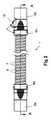
- FIG. 1shows a preferred embodiment of the hose 1 according to the present invention.
- the flexible plastic hose 1comprises:
- the hose according to the present inventionhas a separate stress relief element 4 which is designed to match dimensions of the supporting rib 8 of the hose body 2.
- the stress relief element 4is screwed onto the hose body 2 prior to moulding the cuff 3 onto the hose body 2.
- the stress relief element 4fits closely around the hose body 2 but is not directly bonded to the hose body 2, which allows the hose body 2 to move slightly within the stress relief element 4.
- the stress relief element 4is over-moulded when the cuff 3 is moulded onto the hose body 2 and therefore becomes bonded with the cuff 3.
- the stressis distributed over several pitches of the helical rib 8, rather than at one stress concentration point. This reduces the risk of failure of the hose body 2 at the joint between the cuff 3 and the hose body 2.
- the stress relief element 4acts as a rigid sleeve to lock the tubular hose body 2 in place.
- the internal screw-threadrestricts the bending or stretching of the part of the hose body which it holds.
- the hose shown in figure 1has a flexible hollow tubular body 2 of a desired length, depending on the application.
- the hose body 2preferably has a relatively thin web (e.g. 1.0 mm thick), which is reinforced by a helical rib 8 extending over the entire length of the flexible body 2.
- a relatively thin webe.g. 1.0 mm thick
- a helical rib 8extending over the entire length of the flexible body 2.
- the at least one helical reinforcing rib 8has predetermined properties (e.g. thickness, material, pitch, etc) for providing sufficient mechanical strength and stiffness to the hose body 2.
- the helical rib 8comprises polypropylene surrounded by polyolefin.
- the helical rib 8comprises polyethylene surrounded by polyolefin, but other materials may also be used.
- the ribcomprises at least one material selected from the group consisting of: polypropylene, polyethylene, and any other material approved according to ISO 10993 for use in medical applications, preferably this material being surrounded by a coating comprising the same material as is used in the web, or a material compatible therewith. This material selection enhances the adhesion between the rib and the web.
- the ribmay e.g. have a substantially circular cross section with a diameter of e.g. 1.0 - 3.0 mm, or a substantially elliptical cross section with a width W of e.g 2.70 mm and a height T of e.g. 1.70 mm ( Fig. 6 ), but other dimensions and other shapes may also be used.
- a substantially circular cross sectionwith a diameter of e.g. 1.0 - 3.0 mm, or a substantially elliptical cross section with a width W of e.g 2.70 mm and a height T of e.g. 1.70 mm ( Fig. 6 ), but other dimensions and other shapes may also be used.
- As the rib 8is used as screw thread in the stress relief element 4, it should have at least 1.00 mm thickness for most consumer or medical applications.
- the hose body 2comprises web portions 7 having predetermined properties (e.g. dimensions, material, etc) chosen for providing desired flexibility to the hose body 2.
- the width of the web portions 7 between two successive rib portions 8is 1.0 - 10.0 mm, more preferably 6.0 - 7.0 mm.
- the hosehas a single helical rib 8, and the pitch of that helix is substantially 6.4 mm.
- the pitch p of the reinforcing ribs of the flexible plastic hose according to the present inventionis preferably in the range of 3.0 to 9.0 mm, more preferably 4.0 to 8.0 mm, even more preferably 5.0 to 7.0 mm, and most preferably about 6.2 mm.
- the pitchis conventionally measured as shown in Fig. 4 from the top of one rib to the top of the adjacent rib.
- the ribshave a width of at least 0.05 mm [IS THIS OK, OR SHOULD IT BE 0.5 MM?], preferably at least 1.0 mm, more preferably at least 1.5 mm, optionally at most 4.0 mm, preferably at most 3.0 mm, more preferably at most 2.5 mm, even more preferably at most 2.0 mm, and typically 1.7 ⁇ 0.2 mm.
- the ribhas a height of at least 0.05 mm, preferably at least 0.05 mm [IS THIS OK, OR SHOULD IT BE 0.5 MM?], preferably at least 1.0 mm, more preferably at least 2.0 mm, optionally at most 5.0 mm, preferably at most 4.0 mm, more preferably at most 3.5 mm, even more preferably at most 3.0 mm and typically 2.7 ⁇ 0.2 mm.
- the width of the web portions 7should be at least 1.0 mm between the rib portions 8 in order to provide sufficient flexibility.
- the radial thickness of the web portions 7 of the hose 1 of the present inventionis preferably 0.10 - 0.25 mm, more preferably 0.16 - 0.22 mm. This allows for a very flexible hose, which can easily bend over 90° under a weight of e.g. 0.100 kg or 0.200 kg.
- the webis transparent, so that flow of the fluid (gas or liquid) inside the tube may be visible.
- the web portions 7are made of a material chosen from the group consisting of: polyolefin, metallocene PE, polyvinylchloride (PVC), preferably flexible PVC, and any other material approved according to ISO 10993 for use in medical applications.
- the hose of Fig. 1has at its both ends a first and a second cuff 3a, 3b, but the hose of the present invention may only comprise a single cuff 3.
- both cuffs 3a, 3b of Fig. 1are substantially identical, and therefore only one will be described in detail further.
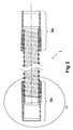
- Fig. 2shows the hose 1 of Fig. 1 in side view.
- Fig. 3shows the hose 1 of Fig. 2 in cross-section along line A-A.
- the cuff 3a, 3bare substantially identical, therefore only one of them will be described further.
- Fig. 4shows a preferred embodiment of the cuff 3 of the hose 1 of the present invention, and its connection with the hose body 2 in more detail.
- a stress relief element 4is screwed on the hose body 2, in such a way that part of the hose body 2 extends beyond the stress relief element 4 (distance L1), and then an end fitting 5 is applied by over-moulding the hose body 2 and at least part of the stress relief element 4.
- the resulting cuff 3then comprises two parts: an end fitting 5 located at and bonded to the extremity 16 of the hose body 2, and a stress relief element 4 located between the end fitting 5 and the entrance 19 of the cuff 3 where the hose body 2 enters the cuff 3.
- the stress relief element 4has a first segment S1 (see also Fig. 5 ) with an internal screw-thread 15 for receiving the complementary helical reinforcing rib 8 for closely fitting around the hose body 2 without being bonded the helical rib 8 (e.g. by gluing) to the stress relief element 4.
- a larger part of the hose body 2in particular the enforcing rib 8) contributes for counteracting any external forces, in particular bending forces and/or pulling forces exerted upon the hose body 2. This effectively lowers the force (and corresponding stress) exerted upon the part of the hose body 2 bonded in the end fitting 5, thereby reducing the risk of damaging the hose 1, in particular the web portions 7.
- the end fitting 5typically has a bore 14, (e.g. a cylindrical or conical bore) for connecting the hose 1 to an external device, e.g. a respiratory device (not shown) on one side of the hose 1, and a mouth piece (not shown) on the other side.
- a bore 14e.g. a cylindrical or conical bore
- the stress relief element 4further comprises a second, substantially cylindrical segment S2 (see Fig. 4 and Fig. 5 ) at the entrance side 19 of the cuff 3, having an inner diameter d3 provided for closely fitting around the helical reinforcing rib 8 in axial direction, but allowing flexibility of the hose body 2 in its longitudinal direction.
- This second segment of the stress relief element 4without screw-thread, allows the hose body 2 to move within the stress relief element without rubbing of the hose body. Tests have shown that this second segment S2 is particularly useful to counteract bending forces, as it allows the hose body 2 to slightly deform already in the cylindrical part S2, without forcing the ribs in an enclosure. This further reduces the stress concentration exerted upon the extremity 16.
- the stress relief element 4further comprises a first and a second substantially cylindrical outer surface 20, 21 having a first resp. second outer diameter d1, d2, the first cylindrical outer surface 20 being provided for overmoulding for increasing the bonding area between the moulded end fitting 5a and the stress relief element 4, as shown in Fig. 4 and Fig. 5 .
- the first cylindrical outer surfaceextends between the first shoulder 11 and the second shoulder 12. The larger the distance between the first and second shoulders 11 and 12, the larger the first substantially cylindrical area becomes, and the larger the bonding becomes between the end fitting 5 and the stress relief part 4.
- the end fitting 5could have been overmoulded over the entire stress relief part 4, but this would result in a larger outer diameter of the cuff 3, which is not desirable.
- the first cylindrical outer surface 20further comprises protrusions 13 and/or recessions (not shown) for also providing a mechanical connection between the moulded end fitting 5 and the stress relief element 4.
- protrusionsmay e.g. take the form of teeth, or a flange at the shoulder edge, but also other techniques may be used.
- the roughness of the first outer surface 20could also be increased by sandblasting.
- the size of the first segment S1 of the stress relief element 4is chosen such that the internal screw thread 15 of the stress release element 4 extends over at least half a winding of the helical reinforcing rib 8, preferably at least one winding, more preferably at least two windings, so that when the hose is pulled or bent, the stress relief element 4 allows the stress exerted upon the hose body 2 to be distributed over several pitches of the enforcing rib 8, rather than at one stress concentration point.
- the person skilled in the artcan find a suitable number of windings by carrying out routine tests.
- the minimum of half a windingapplies especially to a hose with a double-helix rib 8.
- the minimum of one windingapplies especially to a hose with a single helix rib 8.
- the size of the second segment S2is preferably at least one pitch p of the hose.
- the end fitting 5preferably comprises a material selected from the group of polypropylene, polyethylene, polyester and any other material approved according to ISO 10993 for use in medical applications.
- the cuff 3is made of the same material as the rib 8, so that good cohesion of the end fitting 5 and the hose body extending the stress relief element 4 can be achieved.
- the cuff 3may be made of polyolefin. In case of polyester, Hitrel® has been found very suitable.
- Fig. 6shows part of the hose body 2 of Fig. 4 in more detail.
- at least one electrical wire 9is integrated into the outer wall of the hose body 2, the electrical wire 9 preferably being located inside and being isolated by the reinforcing ribs 8.
- two electrical wiresare integrated in the helical enforcing rib 8.
- the wiresare copper wires, having a diameter of substantially 0.29 mm, but other dimensions and other materials may also be used.
- one or more electrical wires 9are present, they are preferably connected to an electrical interface 18 integrated in the end fitting 5 of the cuff 3, as shown in Fig. 1 or Fig. 2 .
- the electrical wire 9may be a heating resistance, a communication wire or both.
- the flexible plastic hose 1 described abovemay be used advantageously as a medical hose, provided that plastic materials suitable for medical purposes are used, more preferably materials approved according to ISO 10993 for use in medical applications.
- the hose 1is a medical hose comprising at least one electrical wire, integrated into the outer wall of the hose body 2, preferably being located inside and isolated by the reinforcing ribs 8, but possibly alternatively in the web or in the weld, and being used for instance for a purpose selected from (i) warming up a fluid (gas and/or liquid) inside the hose body 2, (ii) as a temperature sensor, (iii) as a humidity sensor, (iv) as a sensor for the presence of any chemical component such as e.g. oxygen and/or carbon dioxide presence, and (v) for any other type of sensor, as well as for electrically connecting to a heating device or a sensor.
- the heating wiremay be made accessible for electric power via an interface 18 in the cuff 3 which may be moulded onto the extremity of the hose body 2.
- the electrical wiremay comprise any electrically conductive material, such as a metal, preferably copper but also aluminium, gold or silver would be very suitable. Also any conductive plastic compound may be suitable.
- the hose 1 of the present inventionmay for example be used in a respiratory device such as a CPAP (Continuous Positive Airway Pressure) device.
- CPAPContinuous Positive Airway Pressure
- the corrugated outer surfacemay be implemented by folded web portions 7.
- the flexible body 2may also have multiple helical ribs 8, for example two or more.
- the hosefurther comprises a heating element, preferably a co-axial cable construction which extends in longitudinal direction of the hose body 2, the cable construction comprising two electrical wires 9, one of which being a heating wire and the other being provided for feedback purposes, the two electrical wires 9 being separated by a negative temperature coefficient (NTC) component.
- NTCnegative temperature coefficient
- Such a co-axial cable constructionhas the advantage that it has a very small diameter, so that it can be associated with the hose in a number of different ways, such as for instance in a rib 8 in the wall of the hose, in a wire groove at the inside of the hose 2 or the outside of the hose, wound like a spring.
- the pitch p of the helical ribs 8may be constant or may vary in longitudinal direction of the hose 1. The latter is for instance done in case a heater wire is inserted and an intensive heating is for instance desired in the centre of the hose and a less intensive heating is desired near the edges of the hose 1.
- Each of the helical ribs 8may be provided for carrying one or more wires 9. Some of the ribs 8 may not carry any wires. Different ribs 8 may also differ in width and height, depending of the type and number of wires 9 to be carried.
- the conduitmay comprise more than two helical ribs.
- Fig. 1shows an electrical interface 18 at one end, but in an alternative embodiment an interface 18 is provided at both ends.
Landscapes
- Engineering & Computer Science (AREA)
- General Engineering & Computer Science (AREA)
- Health & Medical Sciences (AREA)
- Mechanical Engineering (AREA)
- Heart & Thoracic Surgery (AREA)
- Anesthesiology (AREA)
- Hematology (AREA)
- Life Sciences & Earth Sciences (AREA)
- Animal Behavior & Ethology (AREA)
- General Health & Medical Sciences (AREA)
- Public Health (AREA)
- Veterinary Medicine (AREA)
- Biomedical Technology (AREA)
- Pulmonology (AREA)
- Emergency Medicine (AREA)
- Rigid Pipes And Flexible Pipes (AREA)
Description
- The invention relates to a flexible plastic hose according to the preamble of the first claim, and to a method for manufacturing such a flexible plastic hose.
- A known hose comprises a flexible hose body having an outer wall with a reinforcing rib extending helically around the outer wall, the rib containing one or more electrical conductors. These electrical conductors are connected to an interface which is provided in one of the cuffs which are provided on the extremities of the hose body. The connector cuffs are manufactured onto the extremities of the hose body by moulding the cuff material directly onto the extremities. It has been found that the outer wall of the flexible hose body can be easily damaged at the transition point between the flexible hose body and the connector cuffs, when the hose is bent and/or pulled.
- Flexible hose connector cuffs are known from
US 3 008 738 A (corresponding to the preamble of claim 1),GB 2 065 823 ADE 196 40 742 A1 . - It is an object of the present invention to provide a flexible plastic hose that is able to resist a higher bending and pulling force exerted between its end fittings.
- This object is achieved according to the present invention with a flexible plastic hose having all the technical characteristics of the first independent claim.
- Thereto the flexible plastic hose according to the present invention comprises:
- a hose body having a flexible tubular outer wall comprising web portions alternating with reinforcing rib portions of at least one helical reinforcing rib, the web portions having predetermined properties chosen for providing flexibility to the hose body, and the at least one reinforcing rib having predetermined properties for providing crush resistance to the hose body;
- a cuff mounted to at least a first extremity of the hose body and comprising a moulded end fitting having a bore for connecting the hose to another device, the end fitting being bonded to the first extremity of the hose body;
- characterised in that the cuff further comprises a stress relief element located at an entrance side of the cuff where the hose body enters the cuff, the stress relief element having a first segment with an internal screw-thread complementary to the helical reinforcing rib for closely fitting around the hose body without being bonded to the first extremity of the hose body, thereby reducing stress exerted on the web portions at the first extremity during use of the hose.
- By providing a cuff comprising a stress relief element having a first segment with an internal screw thread complementary to the helical reinforcing rib, and by bonding the hose body to the cuff not at its entrance position but at the hose extremity being located beyond the stress relief element, the stress relief element actually encloses the hose body without being bonded thereto, allowing some freedom of movement of the hose body therein. The inventor found that this stress relief element allows forces exerted upon the hose body (during use) to be distributed over a larger contact area of the hose body, thereby avoiding or reducing stress concentrations in the hose body, in particular in its web portions.
- In the cuff of the present invention, the stress relief element encloses the hose body without being secured thereto, and the securing of the hose body to the cuff only happens at the moulded end fitting, i.e. a distance from the entrance side of the cuff. Apparently in this way the forces exerted upon the hose body are spread over a larger area of the hose body, and the remaining forces exerted upon the hose extremities are reduced, so that the hose can withstand higher external bending and pulling forces.
Additional features of the invention are disclosed in the dependent claims. - Preferably the stress relief element further comprises a second, substantially cylindrical segment at the entrance side of the cuff, having an inner diameter provided for closely fitting around the reinforcing rib in axial direction but allowing flexibility of the hose body in its longitudinal direction.
- This thread-less second segment of the stress relief element allows even more movement of the hose body within the stress relief element. In particular it allows movement in longitudinal direction of the cuff without rubbing of the hose. The inventor found that this cylindrical segment seems especially advantageous when bending forces are applied to the hose, probably due to the fact that the cylindrical segment allows a higher degree of deformation of the hose body outside of the threaded segment. Thus the cylindrical segment of the stress relief element allows an even further reduction of the stress exerted upon the hose body, in particular on the web portions.
- Preferably the stress relief element further comprises a first and a second substantially cylindrical outer surface having a first resp. second outer diameter, the first cylindrical outer surface being provided for being overmoulded with the material of the moulded end fitting, which increases the bonding area between the moulded end fitting and the stress relief element.
- A larger bonding area improves the connection of the moulded end fitting to the stress relieve element screwed around the hose body, to obtain a rigid cuff.
- The first and/or the second outer surface of the stress relief element do not necessarily need to be substantially cylindrical in shape, as long as the effect of an increased bonding area is provided. The surface may for instance also be conical or elliptical.
- The connection of the cuff to the hose does not necessarily need to be achieved by overmoulding, as long as the connection responds to the desired properties, such as the mechanical properties and/or an acceptable isolation of the inside of the hose from the outside environmnent of the hose. Any other suitable process for connecting the cuff to the hose may be used, such as for instance through spin welding, or by screwing.
- Preferably the first cylindrical outer surface further comprises protrusions and/or recessions for also providing a mechanical lock between the moulded end fitting and the stress relief element.
- When overmoulding the stress relief element for forming the cuff, these protrusions and/or recessions provide for an improved mechanical grip between the end fitting and the stress relief element.
- Preferably the internal screw thread extends over at least half a winding of the helical reinforcing rib, preferably at least one winding, more preferably at least two windings.
- It has been found that half a winding can be sufficient, but a full or multiple windings allow for an even better stress reduction. When the hose is pulled or bent, the stress relief element allows the stress to be distributed over several windings of the reinforcing rib, rather than at one stress concentration point. This substantially reduces the risk of failure of the hose at the joint between the cuff and the hose body.
- It is a further object of the present invention to provide a method for manufacturing such a flexible plastic hose. This further object is achieved with the manufacturing method of the second independent claim.
- Thereto the method of the present invention comprises the following steps:
- a) providing a hose body having a flexible tubular outer wall comprising web portions alternating with reinforcing rib portions of at least one helical reinforcing rib, the web portions having predetermined properties chosen for providing flexibility to the hose body and the at least one reinforcing rib having predetermined properties for providing crush resistance to the hose body;
- b) providing a stress relief element having a first segment with an internal screw thread complementary to the helical reinforcing rib and provided for closely fitting around the hose body (2);
- c) screwing the stress relief element on a first extremity of the hose body, such that the helical reinforcement rib is engaged in the internal thread of the stress relief element, and in such a way that the first extremity of the hose body extends beyond the stress relief element;
- d) moulding or spin welding an end fitting having a bore onto the extremity of the hose body and over part of the stress relief element, such that the end fitting is bonded to the extremity and the stress relief element.
- In other words, the stress relief element, which is designed to match dimensions of the supporting rib of the hose body, is screwed onto the hose body prior to moulding the cuff onto the hose body. As the stress relief element is not directly bonded to the hose body, the step of bonding (e.g. gluing the hose body can be omitted. Next, the stress relief element itself is bonded to the cuff by partly overmoulding it, thereby forming the cuff.
- The invention will be further elucidated by means of the following description and the appended drawings.
- Fig. 1
- shows a perspective view of a preferred embodiment of the flexible plastic hose according to the present invention.
- Fig. 2
- shows the hose of
Fig. 1 in side view. - Fig. 3
- shows the hose of
Fig. 2 in cross-section along line A-A. - Fig. 4
- shows in more detail the cuff of the hose of
Fig 3 . - Fig. 5
- shows in more detail the stress relief element of the cuff of
Fig 4 . - Fig. 6
- shows in more detail part of the hose body of
Fig 4 . - 1
- hose
- 2
- body
- 3
- cuff
- 4
- stress relief element
- 5
- end fitting
- 6
- wire exit
- 7
- web
- 8
- helical rib
- 9
- electrical wire
- 10
- recess
- 11
- first shoulder
- 12
- second shoulder
- 13
- protrusions (or recessions)
- 14
- bore
- 15
- internal screw thread
- 16
- extremity
- 18
- electrical interface
- 19
- entrance side of cuff
- 20
- first cylindrical outer surface
- 21
- second cylindrical outer surface
- p
- pitch
- The present invention will be described with respect to particular embodiments and with reference to certain drawings but the invention is not limited thereto but only by the claims. The drawings described are only schematic and are non-limiting. In the drawings, the size of some of the elements may be exaggerated and not drawn on scale for illustrative purposes. The dimensions and the relative dimensions do not necessarily correspond to actual reductions to practice of the invention.
- Furthermore, the terms first, second, third and the like in the description and in the claims, are used for distinguishing between similar elements and not necessarily for describing a sequential or chronological order. The terms are interchangeable under appropriate circumstances and the embodiments of the invention can operate in other sequences than described or illustrated herein.
- Moreover, the terms top, bottom, over, under and the like in the description and the claims are used for descriptive purposes and not necessarily for describing relative positions. The terms so used are interchangeable under appropriate circumstances and the embodiments of the invention described herein can operate in other orientations than described or illustrated herein.
- The term "comprising", used in the claims, should not be interpreted as being restricted to the means listed thereafter; it does not exclude other elements or steps. It needs to be interpreted as specifying the presence of the stated features, integers, steps or components as referred to, but does not preclude the presence or addition of one or more other features, integers, steps or components, or groups thereof. Thus, the scope of the expression "a device comprising means A and B" should not be limited to devices consisting only of components A and B. It means that with respect to the present invention, the only relevant components of the device are A and B.
- Crush resistance is the resistance a hose provides against collapsing of the hose under lateral pressure, such as when one would stand on a hose laying on the floor. Crush resistance may also be called hub strength or hoop strength, and is an important feature for a flexible hose in many of its applications.
- Flexible hoses for connection between two devices are known in the art, for example for connecting a vacuum cleaner to a cleaning brush, or for connecting a medical breathing device to a mouth-piece, but the invention is not restricted thereto, and can also be used for other hoses. The hoses typically have a ribbed flexible tubular body, and a cuff mounted at each end of the tubular body, for connecting the hose to external devices.
- Different ways of mounting the cuff are known in the art. In one such embodiment the cuff is directly moulded on the tubular hose, which provides for a tight connection, but has the disadvantage of showing stress concentration at the location where the tubular hose body enters the cuff, which will ultimately break when the hose is subjected to bending or pulling forces during use of the hose.
- The flexible hose shown in the drawings is better able to withstand such bending or pulling forces.
Figure 1 shows a preferred embodiment of thehose 1 according to the present invention. The flexibleplastic hose 1 comprises:- a
hose body 2 having a flexible tubular outer wall comprisingweb portions 7 alternating with reinforcing rib portions of at least one helical reinforcingrib 8, theweb portions 7 having predetermined properties chosen for providing flexibility to thehose body 2 and the at least one reinforcingrib 8 having predetermined properties for providing sufficient crush resistance to the hose body 1 (i.e. for preventing it from collapsing and for making it capable to withstand pressure exerted on the outer wall of the hose and upon release of the pressure, returning the outer wall to the original shape - required crush resistance depends on the application); - a
cuff 3a mounted to a first extremity of thehose body 2 and comprising a moulded end fitting 5a having abore 14 for connecting thehose 1 to another device, the end fitting 5a being bonded to the first extremity 16a of thehose body 2; - the
cuff 3 further comprises astress relief element 4 located at anentrance side 19 of thecuff 3 where thehose body 2 enters thecuff 3, thestress relief element 4 having a first segment S1 with an internal screw-thread 15 complementary to the helical reinforcingrib 8 for closely fitting around thehose body 2 without being bonded to the first extremity 16a of thehose body 2, thereby reducing stress exerted on theweb portions 7 at thefirst extremity 16 during use of thehose 1. - The hose according to the present invention has a separate
stress relief element 4 which is designed to match dimensions of the supportingrib 8 of thehose body 2. Thestress relief element 4 is screwed onto thehose body 2 prior to moulding thecuff 3 onto thehose body 2. Thestress relief element 4 fits closely around thehose body 2 but is not directly bonded to thehose body 2, which allows thehose body 2 to move slightly within thestress relief element 4. Thestress relief element 4 is over-moulded when thecuff 3 is moulded onto thehose body 2 and therefore becomes bonded with thecuff 3. When thehose body 2 is pulled or bent with thestress relief element 4 in place, the stress is distributed over several pitches of thehelical rib 8, rather than at one stress concentration point. This reduces the risk of failure of thehose body 2 at the joint between thecuff 3 and thehose body 2. - The
stress relief element 4 acts as a rigid sleeve to lock thetubular hose body 2 in place. When an external bending or pulling force is applied to thehose body 2, the internal screw-thread restricts the bending or stretching of the part of the hose body which it holds. - The hose shown in
figure 1 has a flexible hollowtubular body 2 of a desired length, depending on the application. Thehose body 2 preferably has a relatively thin web (e.g. 1.0 mm thick), which is reinforced by ahelical rib 8 extending over the entire length of theflexible body 2. Several methods for manufacturing such a tubular body are described in the art, for example in one embodiment thewebs 7 andribs 8 may be coextruded and subsequently wound on a mandrel, in a way as described inUS 4,162,370 . As this is not the focus of the present invention, no further explanation is deemed necessary here. - The at least one helical reinforcing
rib 8 has predetermined properties (e.g. thickness, material, pitch, etc) for providing sufficient mechanical strength and stiffness to thehose body 2. In a preferred embodiment thehelical rib 8 comprises polypropylene surrounded by polyolefin. In another preferred embodiment thehelical rib 8 comprises polyethylene surrounded by polyolefin, but other materials may also be used. In an embodiment, the rib comprises at least one material selected from the group consisting of: polypropylene, polyethylene, and any other material approved according to ISO 10993 for use in medical applications, preferably this material being surrounded by a coating comprising the same material as is used in the web, or a material compatible therewith. This material selection enhances the adhesion between the rib and the web. - The rib may e.g. have a substantially circular cross section with a diameter of e.g. 1.0 - 3.0 mm, or a substantially elliptical cross section with a width W of e.g 2.70 mm and a height T of e.g. 1.70 mm (
Fig. 6 ), but other dimensions and other shapes may also be used. As therib 8 is used as screw thread in thestress relief element 4, it should have at least 1.00 mm thickness for most consumer or medical applications. - Between the
rib portions 8, thehose body 2 according to the present invention comprisesweb portions 7 having predetermined properties (e.g. dimensions, material, etc) chosen for providing desired flexibility to thehose body 2. In a preferred embodiment of the hose according to the present invention, the width of theweb portions 7 between twosuccessive rib portions 8 is 1.0 - 10.0 mm, more preferably 6.0 - 7.0 mm. In an example the hose has a singlehelical rib 8, and the pitch of that helix is substantially 6.4 mm. - In an embodiment, the pitch p of the reinforcing ribs of the flexible plastic hose according to the present invention is preferably in the range of 3.0 to 9.0 mm, more preferably 4.0 to 8.0 mm, even more preferably 5.0 to 7.0 mm, and most preferably about 6.2 mm. The pitch is conventionally measured as shown in
Fig. 4 from the top of one rib to the top of the adjacent rib. - In another embodiment according to additional features of the present invention, the ribs have a width of at least 0.05 mm [IS THIS OK, OR SHOULD IT BE 0.5 MM?], preferably at least 1.0 mm, more preferably at least 1.5 mm, optionally at most 4.0 mm, preferably at most 3.0 mm, more preferably at most 2.5 mm, even more preferably at most 2.0 mm, and typically 1.7 ± 0.2 mm.
- In yet another embodiment according to additional features of the present invention, the rib has a height of at least 0.05 mm, preferably at least 0.05 mm [IS THIS OK, OR SHOULD IT BE 0.5 MM?], preferably at least 1.0 mm, more preferably at least 2.0 mm, optionally at most 5.0 mm, preferably at most 4.0 mm, more preferably at most 3.5 mm, even more preferably at most 3.0 mm and typically 2.7 ± 0.2 mm.
- The width of the
web portions 7 should be at least 1.0 mm between therib portions 8 in order to provide sufficient flexibility. The radial thickness of theweb portions 7 of thehose 1 of the present invention is preferably 0.10 - 0.25 mm, more preferably 0.16 - 0.22 mm. This allows for a very flexible hose, which can easily bend over 90° under a weight of e.g. 0.100 kg or 0.200 kg. Optionally the web is transparent, so that flow of the fluid (gas or liquid) inside the tube may be visible. Preferably theweb portions 7 are made of a material chosen from the group consisting of: polyolefin, metallocene PE, polyvinylchloride (PVC), preferably flexible PVC, and any other material approved according to ISO 10993 for use in medical applications. - The hose of
Fig. 1 has at its both ends a first and asecond cuff single cuff 3. Apart from theelectrical interface 18, which is not the focus of the present invention, bothcuffs Fig. 1 are substantially identical, and therefore only one will be described in detail further. Fig. 2 shows thehose 1 ofFig. 1 in side view.Fig. 3 shows thehose 1 ofFig. 2 in cross-section along line A-A. As can be seen, thecuff Fig. 4 shows a preferred embodiment of thecuff 3 of thehose 1 of the present invention, and its connection with thehose body 2 in more detail. During manufacture of thehose 1, first astress relief element 4 is screwed on thehose body 2, in such a way that part of thehose body 2 extends beyond the stress relief element 4 (distance L1), and then anend fitting 5 is applied by over-moulding thehose body 2 and at least part of thestress relief element 4. The resultingcuff 3 then comprises two parts: an end fitting 5 located at and bonded to theextremity 16 of thehose body 2, and astress relief element 4 located between the end fitting 5 and theentrance 19 of thecuff 3 where thehose body 2 enters thecuff 3. Thestress relief element 4 has a first segment S1 (see alsoFig. 5 ) with an internal screw-thread 15 for receiving the complementary helical reinforcingrib 8 for closely fitting around thehose body 2 without being bonded the helical rib 8 (e.g. by gluing) to thestress relief element 4. By not bonding thehose body 2 to thestress relief element 4 directly, but allowing some movement therein, a larger part of the hose body 2 (in particular the enforcing rib 8) contributes for counteracting any external forces, in particular bending forces and/or pulling forces exerted upon thehose body 2. This effectively lowers the force (and corresponding stress) exerted upon the part of thehose body 2 bonded in the end fitting 5, thereby reducing the risk of damaging thehose 1, in particular theweb portions 7.- The end fitting 5 typically has a
bore 14, (e.g. a cylindrical or conical bore) for connecting thehose 1 to an external device, e.g. a respiratory device (not shown) on one side of thehose 1, and a mouth piece (not shown) on the other side. - In a preferred embodiment of the flexible
plastic hose 1 according to the present invention, thestress relief element 4 further comprises a second, substantially cylindrical segment S2 (seeFig. 4 andFig. 5 ) at theentrance side 19 of thecuff 3, having an inner diameter d3 provided for closely fitting around the helical reinforcingrib 8 in axial direction, but allowing flexibility of thehose body 2 in its longitudinal direction. This second segment of thestress relief element 4, without screw-thread, allows thehose body 2 to move within the stress relief element without rubbing of the hose body. Tests have shown that this second segment S2 is particularly useful to counteract bending forces, as it allows thehose body 2 to slightly deform already in the cylindrical part S2, without forcing the ribs in an enclosure. This further reduces the stress concentration exerted upon theextremity 16. - In the preferred embodiment of the
hose 1 according to the invention, thestress relief element 4 further comprises a first and a second substantially cylindricalouter surface outer surface 20 being provided for overmoulding for increasing the bonding area between the moulded end fitting 5a and thestress relief element 4, as shown inFig. 4 andFig. 5 . The first cylindrical outer surface extends between thefirst shoulder 11 and thesecond shoulder 12. The larger the distance between the first andsecond shoulders stress relief part 4. Alternatively the end fitting 5 could have been overmoulded over the entirestress relief part 4, but this would result in a larger outer diameter of thecuff 3, which is not desirable. - Preferably the first cylindrical
outer surface 20 further comprisesprotrusions 13 and/or recessions (not shown) for also providing a mechanical connection between the moulded end fitting 5 and thestress relief element 4. Such protrusions may e.g. take the form of teeth, or a flange at the shoulder edge, but also other techniques may be used. For example, the roughness of the firstouter surface 20 could also be increased by sandblasting. - Preferably the size of the first segment S1 of the
stress relief element 4 is chosen such that theinternal screw thread 15 of thestress release element 4 extends over at least half a winding of the helical reinforcingrib 8, preferably at least one winding, more preferably at least two windings, so that when the hose is pulled or bent, thestress relief element 4 allows the stress exerted upon thehose body 2 to be distributed over several pitches of the enforcingrib 8, rather than at one stress concentration point. This reduces the risk of damage to thehose 1 under bending and/or pulling forces. In general, the more windings, the lower the stress, and the higher the external forces may be before damage occurs. The person skilled in the art can find a suitable number of windings by carrying out routine tests. The minimum of half a winding applies especially to a hose with a double-helix rib 8. The minimum of one winding applies especially to a hose with asingle helix rib 8. - The size of the second segment S2 is preferably at least one pitch p of the hose.
- The end fitting 5 preferably comprises a material selected from the group of polypropylene, polyethylene, polyester and any other material approved according to ISO 10993 for use in medical applications. Preferably the
cuff 3 is made of the same material as therib 8, so that good cohesion of the end fitting 5 and the hose body extending thestress relief element 4 can be achieved. Alternatively thecuff 3 may be made of polyolefin. In case of polyester, Hitrel® has been found very suitable. Fig. 6 shows part of thehose body 2 ofFig. 4 in more detail. Optionally at least oneelectrical wire 9 is integrated into the outer wall of thehose body 2, theelectrical wire 9 preferably being located inside and being isolated by the reinforcingribs 8. InFig. 6 two electrical wires are integrated in the helical enforcingrib 8. In an embodiment the wires are copper wires, having a diameter of substantially 0.29 mm, but other dimensions and other materials may also be used. If one or moreelectrical wires 9 are present, they are preferably connected to anelectrical interface 18 integrated in the end fitting 5 of thecuff 3, as shown inFig. 1 orFig. 2 . Theelectrical wire 9 may be a heating resistance, a communication wire or both.- The flexible
plastic hose 1 described above, may be used advantageously as a medical hose, provided that plastic materials suitable for medical purposes are used, more preferably materials approved according to ISO 10993 for use in medical applications. - In a particular use, the
hose 1 is a medical hose comprising at least one electrical wire, integrated into the outer wall of thehose body 2, preferably being located inside and isolated by the reinforcingribs 8, but possibly alternatively in the web or in the weld, and being used for instance for a purpose selected from (i) warming up a fluid (gas and/or liquid) inside thehose body 2, (ii) as a temperature sensor, (iii) as a humidity sensor, (iv) as a sensor for the presence of any chemical component such as e.g. oxygen and/or carbon dioxide presence, and (v) for any other type of sensor, as well as for electrically connecting to a heating device or a sensor. In this case, in particular for heating, the heating wire may be made accessible for electric power via aninterface 18 in thecuff 3 which may be moulded onto the extremity of thehose body 2. The electrical wire may comprise any electrically conductive material, such as a metal, preferably copper but also aluminium, gold or silver would be very suitable. Also any conductive plastic compound may be suitable. - The
hose 1 of the present invention may for example be used in a respiratory device such as a CPAP (Continuous Positive Airway Pressure) device. - For example, the corrugated outer surface may be implemented by folded
web portions 7. Instead of having only onehelical rib 8, theflexible body 2 may also have multiplehelical ribs 8, for example two or more. - In an embodiment the hose further comprises a heating element, preferably a co-axial cable construction which extends in longitudinal direction of the
hose body 2, the cable construction comprising twoelectrical wires 9, one of which being a heating wire and the other being provided for feedback purposes, the twoelectrical wires 9 being separated by a negative temperature coefficient (NTC) component. Such a co-axial cable construction has the advantage that it has a very small diameter, so that it can be associated with the hose in a number of different ways, such as for instance in arib 8 in the wall of the hose, in a wire groove at the inside of thehose 2 or the outside of the hose, wound like a spring. - The pitch p of the
helical ribs 8 may be constant or may vary in longitudinal direction of thehose 1. The latter is for instance done in case a heater wire is inserted and an intensive heating is for instance desired in the centre of the hose and a less intensive heating is desired near the edges of thehose 1. Each of thehelical ribs 8 may be provided for carrying one ormore wires 9. Some of theribs 8 may not carry any wires.Different ribs 8 may also differ in width and height, depending of the type and number ofwires 9 to be carried. The conduit may comprise more than two helical ribs. Fig. 1 shows anelectrical interface 18 at one end, but in an alternative embodiment aninterface 18 is provided at both ends.
Claims (15)
- Flexible plastic hose (1) comprising:- a hose body (2) having a flexible tubular outer wall comprising web portions (7) alternating with reinforcing rib portions of at least one helical reinforcing rib (8), the web portions (7) having predetermined properties chosen for providing flexibility to the hose body (2) and the at least one reinforcing rib (8) having predetermined properties for providing crush resistance to the hose body (1);- a cuff (3a) mounted to at least a first extremity (16a) of the hose body (2) and comprising a moulded end fitting (5a) having a bore (14) for connecting the hose (1) to another device, the end fitting (5a) being bonded to the first extremity (16a) of the hose body (2);
characterised in that- the cuff (3) further comprises a stress relief element (4) located at an entrance side (19) of the cuff (3) where the hose body (2) enters the cuff (3), the stress relief element (4) having a first segment (S1) with an internal screw-thread (15) complementary to the helical reinforcing rib (8) for closely fitting around the hose body (2) without being bonded to the first extremity (16a) of the hose body (2), thereby reducing stress exerted on the web portions (7) at the first extremity (16) during use of the hose (1). - The flexible plastic hose (1) according to claim 1,characterised in that the stress relief element (4) further comprises a second, substantially cylindrical segment (S2) at the entrance side (19) of the cuff (3), having an inner diameter (d3) provided for closely fitting around the reinforcing rib (8) in axial direction but allowing flexibility of the hose body (2) in its longitudinal direction.
- The flexible plastic hose (1) according to claim 1 or 2,characterised in that the stress relief element (4) further comprises a first and a second substantially cylindrical outer surface (20, 21) having a first resp. second outer diameter (d1, d2), the first cylindrical outer surface (20) being provided for being overmoulded with the material of the moulded end fitting (5a).
- The flexible plastic hose (1) according to claim 3,characterised in that the first cylindrical outer surface (20) further comprises protrusions (13) and/or recessions for also providing a mechanical lock between the moulded end fitting (5) and the stress relief element (4).
- The flexible plastic hose (1) according to any one of the previous claims,characterised in that the internal screw thread (15) of the stress release element (4) extends over at least half a winding of the helical reinforcing rib (8), preferably at least one winding, more preferably at least two windings.
- The flexible plastic hose (1) according to any one of the preceding claims,characterised in that the pitch of the rib or ribs (8) is at least 3.0 mm, preferably at least 5.0 mm.
- The flexible plastic hose (1) according to any one of the preceding claims,characterised in that the wall thickness (r) of the web portions (7) is 0.10 - 0.25 mm, preferably 0.16 - 0.22 mm.
- The flexible plastic hose (1) according to any one of the preceding claims,characterised in that the web portions (7) are made of a material chosen from the group comprising: polyolefin, metallocene PE, polyvinylchloride (PVC), preferably flexible PVC, and any other material approved according to ISO 10993 for use in medical applications.
- The flexible plastic hose (1) according to any one of the preceding claims,characterised in that the rib (8) comprises at least one material selected from the group of: polypropylene, polyethylene, and any other material approved according to ISO 10993 for use in medical applications, preferably surrounded by a coating comprising the same material as is used in the web, or a material compatible therewith.
- The flexible plastic hose (1) according to any one of the preceding claims,characterised in that the end fitting (5) comprises a material selected from the group of: polypropylene, polyethylene, polyester and any other material approved according to ISO 10993 for use in medical applications.
- The flexible plastic hose (1) according to any one of the previous claims,characterised in that at least one electrical wire/cable (9) is integrated into the outer wall of the hose body (2), the electrical wire/cable (9) preferably being integrated in the reinforcing ribs (8) or in the web (7).
- The flexible plastic hose (1) according to claim 11,characterised in that the at least one electrical wire/cable (9) is connected to an electrical interface (18) integrated in the end fitting (5) of the cuff (3).
- Method of manufacturing a flexible plastic hose (1), comprising the steps of:a) providing a hose body (2) having a flexible tubular outer wall comprising web portions (7) alternating with reinforcing rib portions of at least one helical reinforcing rib (8), the web portions (7) having predetermined properties chosen for providing flexibility to the hose body (2) and the at least one reinforcing rib (8) having predetermined properties for providing crush resistance to the hose body (1);b) providing a stress relief element (4) having a first segment with an internal screw thread complementary to the helical reinforcing rib (8) provided for closely fitting around the hose body (2);c) screwing the stress relief element (4) on a first extremity of the hose body (2), such that the at least one helical reinforcing rib (8) is engaged in the internal thread (15) of the stress relief element (4), and in such a way that the extremity (16) of the hose body (2) extends beyond the stress relief element (4);d) moulding or spin welding an end fitting (5) having a bore (14) onto the first extremity of the hose body (2) and over part of the stress relief element (4), such that the end fitting (5) is bonded to the first extremity and the stress relief element.
- Medical flexible plastic hose (1) according to any one of claims 1-12,characterised in that the hose (1) is manufactured in predetermined plastic materials suitable for medical purposes.
- Medical flexible plastic hose (1) according to claim 14,characterised in that at least one electrical wire (9) is integrated into the outer wall of the hose body (2), the electrical wire preferably being located inside and isolated by the reinforcing ribs (8), and being provided for a purpose or use selected from (i) warming up a fluid inside the hose body (2), (ii) as a temperature sensor, (iii) as a humidity sensor, (iv) as a sensor for oxygen, carbon dioxide presence, and (v) for any other type of sensor.
Priority Applications (12)
| Application Number | Priority Date | Filing Date | Title |
|---|---|---|---|
| ES11163335TES2432740T3 (en) | 2011-04-21 | 2011-04-21 | Flexible plastic hose and method to manufacture it |
| PL11163335TPL2514478T3 (en) | 2011-04-21 | 2011-04-21 | Flexible plastic hose and method for manufacturing same |
| EP11163335.0AEP2514478B1 (en) | 2011-04-21 | 2011-04-21 | Flexible plastic hose and method for manufacturing same |
| US14/112,697US9784387B2 (en) | 2011-04-21 | 2012-04-23 | Flexible plastic hose and method for manufacturing same |
| MX2013012246AMX2013012246A (en) | 2011-04-21 | 2012-04-23 | Flexible plastic hose and method for manufacturing same. |
| PCT/EP2012/057396WO2012143563A1 (en) | 2011-04-21 | 2012-04-23 | Flexible plastic hose and method for manufacturing same |
| HK14105713.9AHK1192494B (en) | 2011-04-21 | 2012-04-23 | Flexible plastic hose and method for manufacturing same |
| NZ616895ANZ616895B2 (en) | 2011-04-21 | 2012-04-23 | Flexible plastic hose and method for manufacturing same |
| CA2833298ACA2833298C (en) | 2011-04-21 | 2012-04-23 | Flexible plastic hose and method for manufacturing same |
| EP12723121.5AEP2699307B1 (en) | 2011-04-21 | 2012-04-23 | Flexible plastic hose and method for manufacturing same |
| CN201280018769.5ACN103476454B (en) | 2011-04-21 | 2012-04-23 | Flexible plastic hoses and manufacture method thereof |
| MYPI2013003788AMY158136A (en) | 2011-04-21 | 2012-04-23 | Flexible plastic hose and method for manufacturing same |
Applications Claiming Priority (1)
| Application Number | Priority Date | Filing Date | Title |
|---|---|---|---|
| EP11163335.0AEP2514478B1 (en) | 2011-04-21 | 2011-04-21 | Flexible plastic hose and method for manufacturing same |
Publications (2)
| Publication Number | Publication Date |
|---|---|
| EP2514478A1 EP2514478A1 (en) | 2012-10-24 |
| EP2514478B1true EP2514478B1 (en) | 2013-07-31 |
Family
ID=44525633
Family Applications (2)
| Application Number | Title | Priority Date | Filing Date |
|---|---|---|---|
| EP11163335.0AActiveEP2514478B1 (en) | 2011-04-21 | 2011-04-21 | Flexible plastic hose and method for manufacturing same |
| EP12723121.5AActiveEP2699307B1 (en) | 2011-04-21 | 2012-04-23 | Flexible plastic hose and method for manufacturing same |
Family Applications After (1)
| Application Number | Title | Priority Date | Filing Date |
|---|---|---|---|
| EP12723121.5AActiveEP2699307B1 (en) | 2011-04-21 | 2012-04-23 | Flexible plastic hose and method for manufacturing same |
Country Status (9)
| Country | Link |
|---|---|
| US (1) | US9784387B2 (en) |
| EP (2) | EP2514478B1 (en) |
| CN (1) | CN103476454B (en) |
| CA (1) | CA2833298C (en) |
| ES (1) | ES2432740T3 (en) |
| MX (1) | MX2013012246A (en) |
| MY (1) | MY158136A (en) |
| PL (1) | PL2514478T3 (en) |
| WO (1) | WO2012143563A1 (en) |
Cited By (5)
| Publication number | Priority date | Publication date | Assignee | Title |
|---|---|---|---|---|
| CN103438297A (en)* | 2013-08-01 | 2013-12-11 | 江苏星鑫工程管道有限公司 | Improved gas drainage pipe |
| CN104994900A (en)* | 2013-01-10 | 2015-10-21 | 梅丁医疗创新股份有限公司 | Fluid Hose Assembly |
| US9901725B2 (en) | 2012-10-01 | 2018-02-27 | Bayer Healthcare Llc | Overmolded medical connector tubing and method |
| US10828482B2 (en) | 2013-12-20 | 2020-11-10 | Fisher & Paykel Healthcare Limited | Humidification system connections |
| WO2023219557A1 (en)* | 2022-05-12 | 2023-11-16 | Hill-Rom Services Pte. Ltd. | Hose having a magnetic connector |
Families Citing this family (63)
| Publication number | Priority date | Publication date | Assignee | Title |
|---|---|---|---|---|
| DE102008022663B4 (en) | 2008-05-07 | 2012-10-31 | Schauenburg Hose Technology Gmbh | Stretch hose |
| US9505164B2 (en) | 2009-12-30 | 2016-11-29 | Schauenburg Technology Se | Tapered helically reinforced hose and its manufacture |
| US9964238B2 (en) | 2009-01-15 | 2018-05-08 | Globalmed, Inc. | Stretch hose and hose production method |
| US9909699B2 (en)* | 2011-03-17 | 2018-03-06 | Jay G. Bernhardt | Garden hose with spiral guard |
| DK3685877T3 (en) | 2011-06-03 | 2023-10-02 | Fisher & Paykel Healthcare Ltd | MEDICAL TUBES CONSISTING OF CONDUCTIVE FILAMENTS AND METHODS OF PRODUCTION |
| EP3738638A1 (en) | 2012-03-15 | 2020-11-18 | Fisher & Paykel Healthcare Limited | Respiratory gas humidification system |
| GB2575894A (en) | 2012-04-27 | 2020-01-29 | Fisher & Paykel Healthcare Ltd | Usability features for respiratory humidification system |
| GB2575363B (en) | 2012-11-14 | 2020-04-22 | Fisher & Paykel Healthcare Ltd | Zone heating for respiratory circuits |
| GB2527210B (en) | 2012-12-04 | 2020-02-05 | Fisher & Paykel Healthcare Ltd | A Breathing Tube and Method of Manufacturing a Breathing Tube |
| WO2014117179A1 (en) | 2013-01-28 | 2014-07-31 | Hancock Medical, Inc. | Position control devices and methods for use with positive airway pressure systems |
| WO2014205513A1 (en) | 2013-06-25 | 2014-12-31 | Resmed Limited | Outlet connection assembly and method of making the same |
| CN203533038U (en)* | 2013-08-26 | 2014-04-09 | 金华市春光橡塑软管有限公司 | Rubber-coated retainer ring assembly |
| GB2584026B (en) | 2013-09-13 | 2021-03-17 | Fisher & Paykel Healthcare Ltd | A heater base for supplying humidified gases to a patient |
| JP6663850B2 (en) | 2013-09-13 | 2020-03-13 | フィッシャー アンド ペイケル ヘルスケア リミテッド | Humidification system connection |
| US10814091B2 (en) | 2013-10-24 | 2020-10-27 | Fisher & Paykel Healthcare Limited | System for delivery of respiratory gases |
| US9623594B2 (en)* | 2014-02-06 | 2017-04-18 | Steere Enterprises, Inc. | Air duct cuff and method of manufacture |
| US10449319B2 (en) | 2014-02-07 | 2019-10-22 | Fisher & Paykel Healthcare Limited | Respiratory humidification system |
| DE102014102247B4 (en)* | 2014-02-21 | 2017-08-03 | Lemken Gmbh & Co. Kg | Hose plug system of an agricultural distribution machine |
| CN111265754B (en) | 2014-03-17 | 2023-06-06 | 费雪派克医疗保健有限公司 | Medical tube for respiratory system |
| US11173272B2 (en) | 2014-05-02 | 2021-11-16 | Fisher & Paykel Healthcare Limited | Gas humidification arrangement |
| CN110124174A (en) | 2014-05-13 | 2019-08-16 | 费雪派克医疗保健有限公司 | Availability aspect for breathing humidification system |
| CN106535971B (en) | 2014-06-03 | 2020-12-04 | 费雪派克医疗保健有限公司 | Flow mixers for respiratory therapy systems |
| CN112316272B (en) | 2014-07-07 | 2023-10-31 | 费雪派克医疗保健有限公司 | Medical tube and connector for gas delivery system |
| WO2016028525A1 (en) | 2014-08-18 | 2016-02-25 | Hancock Medical, Inc. | Portable pap device with humidification |
| WO2016080847A1 (en) | 2014-11-17 | 2016-05-26 | Fisher & Paykel Healthcare Limited | Humidification of respiratory gases |
| WO2017043981A1 (en) | 2015-09-09 | 2017-03-16 | Po-Yen Liu | Zone heating for respiratory circuits |
| USD807995S1 (en)* | 2015-09-22 | 2018-01-16 | Fisher & Paykel Healthcare Limited | Circuit kit for a humidifier |
| USD841147S1 (en) | 2015-09-30 | 2019-02-19 | Fisher & Paykel Healthcare Limited | Circuit kit for a humidifier |
| US11504492B2 (en)* | 2015-10-08 | 2022-11-22 | ResMed Pty Ltd | Air conduit for a respiratory device |
| EP3457926A4 (en) | 2016-05-19 | 2020-09-09 | Hancock Medical, Inc. | SYSTEM FOR DETECTING POSITIONAL OBSTRUCTIVE SLEEP APNEA |
| CN109475714B (en)* | 2016-06-07 | 2022-09-02 | 菲舍尔和佩克尔保健有限公司 | Breathing circuit component for breathing apparatus |
| WO2017213007A1 (en)* | 2016-06-09 | 2017-12-14 | 株式会社ブリヂストン | Compound tube |
| USD841148S1 (en) | 2016-07-21 | 2019-02-19 | Fisher & Paykel Healthcare Limited | Breathing tube |
| USD882757S1 (en) | 2016-11-30 | 2020-04-28 | ResMed Pty Ltd | Respiratory mask air delivery adapter assembly |
| EP3551978B1 (en) | 2016-12-07 | 2022-01-26 | Fisher&Paykel Healthcare Limited | Sensing arrangements for medical devices |
| EP3544662B1 (en) | 2016-12-22 | 2024-11-27 | Fisher & Paykel Healthcare Limited | Medical tubes and methods of manufacture |
| US11839719B2 (en) | 2017-01-30 | 2023-12-12 | Globalmed, Inc. | Heated respiratory hose wiring |
| US11813403B2 (en) | 2017-01-30 | 2023-11-14 | Globalmed, Inc. | Heated respiratory hose wiring |
| US11052214B2 (en) | 2017-01-30 | 2021-07-06 | Globalmed, Inc. | Heated respiratory hose wiring |
| FR3064336B1 (en)* | 2017-03-21 | 2019-04-19 | Rikksen | DEVICE FOR SEALING BETWEEN TWO COAXIAL CONDUITS AND ASSEMBLY |
| CN106979390B (en)* | 2017-04-26 | 2023-10-13 | 开平市宝来塑胶制品有限公司 | Telescopic hose with triangular thread structure |
| US10316992B2 (en)* | 2017-06-09 | 2019-06-11 | GM Global Technology Operations LLC | Tubing for fluid cooling systems |
| US10947938B2 (en) | 2017-06-21 | 2021-03-16 | Steere Enterprises, Inc. | Air duct assembly with a secured seal |
| JP7630992B2 (en) | 2017-09-18 | 2025-02-18 | フィッシャー アンド ペイケル ヘルスケア リミテッド | FRAME AND HEADGEAR FOR A RESPIRATORY MASK ASSEMBLY - Patent application |
| US10718453B2 (en)* | 2017-11-21 | 2020-07-21 | Flexible Technologies, Inc. | Flexible hose with improved over-molded cuffs and methods of making same |
| DE202017006929U1 (en) | 2017-12-21 | 2018-11-16 | Dräger Safety AG & Co. KGaA | Breathing hose for a respiratory protective device and breathing apparatus |
| PH12020551473B1 (en)* | 2018-02-23 | 2024-03-08 | Fisher & Paykel Healthcare Ltd | Medical tubes for breathing circuit |
| CN108464855A (en)* | 2018-04-18 | 2018-08-31 | 汪娜 | A kind of Multifunctional gynecological medical treatment obstetric apparatus easy to use |
| EP3811033B1 (en)* | 2018-06-20 | 2022-04-20 | AB Sandvik Materials Technology | Tube portion |
| CN109052027B (en)* | 2018-07-24 | 2024-03-15 | 西安斯通管业有限公司 | Method and clamp for transferring large-caliber plastic pipe and composite continuous pipe |
| WO2020095237A1 (en)* | 2018-11-08 | 2020-05-14 | Fisher & Paykel Healthcare Limited | Frame and headgear for respiratory mask system |
| CN113661351A (en)* | 2019-01-30 | 2021-11-16 | 东莞永昇医疗科技有限公司 | Flexible hose with closable cuff, method for manufacturing same, and device comprising same |
| JP6757994B1 (en)* | 2019-04-12 | 2020-09-23 | 株式会社トヨックス | Antistatic flexible tube |
| USD968587S1 (en)* | 2019-07-08 | 2022-11-01 | Fisher & Paykel Healthcare Limited | Breathing tube |
| USD930150S1 (en)* | 2019-08-21 | 2021-09-07 | ResMed Asia Pte Ltd | Patient interface |
| USD941993S1 (en)* | 2019-08-23 | 2022-01-25 | ResMed Pty Ltd | Tube headgear for patient interface |
| USD933814S1 (en) | 2019-08-23 | 2021-10-19 | ResMed Pty Ltd | Patient interface |
| USD937411S1 (en) | 2019-08-30 | 2021-11-30 | Fisher & Paykel Healthcare Limited | Unit end connector |
| CN111365536A (en)* | 2020-02-26 | 2020-07-03 | 陈弘旋 | Telescopic hose and production process thereof |
| CN114103153A (en)* | 2021-11-23 | 2022-03-01 | 陕西智超信息技术有限公司 | Vacuum-resistant externally-reinforced antistatic engineering plastic pipe and processing method thereof |
| CN118575031A (en) | 2022-02-09 | 2024-08-30 | 柔性塑料集团 | Flexible hose with embedded spiral conductor and method for manufacturing such flexible hose |
| EP4502032A1 (en) | 2023-08-03 | 2025-02-05 | Plastiflex Group | Process for recycling mixed waste containing medical consumables |
| US12313197B1 (en)* | 2024-01-18 | 2025-05-27 | Dcstar Inc | Hose connector with an adjustment structure |
Family Cites Families (18)
| Publication number | Priority date | Publication date | Assignee | Title |
|---|---|---|---|---|
| US3008738A (en)* | 1961-11-14 | Longfellow | ||
| NL273812A (en)* | 1961-02-27 | |||
| US3934902A (en)* | 1973-12-18 | 1976-01-27 | Rca Corporation | Connector for a corrugated conduit |
| US3928715A (en)* | 1974-10-31 | 1975-12-23 | Dayco Corp | Vacuum cleaner hose assembly and apparatus and method used in making same |
| US4063790A (en)* | 1976-10-15 | 1977-12-20 | Dayco Corporation | Fluid conduit assembly |
| US4162370A (en) | 1977-06-24 | 1979-07-24 | Automation Industries, Inc. | Current carrying hose assembly |
| US4277640A (en)* | 1979-04-26 | 1981-07-07 | Automation Industries, Inc. | Electric current-carrying hose assembly having end fittings enclosing an electrical switch and/or a circuit-breaking device |
| US4345805A (en)* | 1979-09-17 | 1982-08-24 | Plastiflex Company International | Self-sealing vacuum hose swivel fitting |
| DE8032997U1 (en)* | 1979-12-20 | 1981-04-02 | Smiths Industries Ltd., London | FLEXIBLE TUBE |
| US4462649A (en)* | 1980-05-05 | 1984-07-31 | Dayco Corporation | Hose construction and method of making same |
| US4437691A (en)* | 1981-06-01 | 1984-03-20 | Laney Ralph M | Connector for corrugated tubing |
| DE19640742A1 (en)* | 1996-10-02 | 1998-04-23 | Lobbe Xenex Gmbh & Co | Mounting sleeve for flexible vehicle hose |
| US6099046A (en)* | 1998-10-21 | 2000-08-08 | Seung-Il Oh | Connector for metal ribbed pipe |
| DE20113222U1 (en)* | 2001-08-21 | 2001-11-15 | Truplast Kunststofftechnik GmbH, 35428 Langgöns | Hose line with sleeve |
| DE20114936U1 (en)* | 2001-09-10 | 2001-11-15 | Truplast Kunststofftechnik GmbH, 35428 Langgöns | Vacuum cleaner hose with connection sleeve |
| DE10322972B4 (en)* | 2003-05-21 | 2013-12-24 | Continental Automotive Gmbh | connecting element |
| US6877781B2 (en)* | 2003-07-31 | 2005-04-12 | Highlands Corporation | Corrugated tube fitting |
| US7690695B2 (en)* | 2005-07-18 | 2010-04-06 | Titeflex Corporation | Sealing fitting and seal seat for stainless steel tubing |
- 2011
- 2011-04-21EPEP11163335.0Apatent/EP2514478B1/enactiveActive
- 2011-04-21ESES11163335Tpatent/ES2432740T3/enactiveActive
- 2011-04-21PLPL11163335Tpatent/PL2514478T3/enunknown
- 2012
- 2012-04-23MYMYPI2013003788Apatent/MY158136A/enunknown
- 2012-04-23USUS14/112,697patent/US9784387B2/enactiveActive
- 2012-04-23EPEP12723121.5Apatent/EP2699307B1/enactiveActive
- 2012-04-23CACA2833298Apatent/CA2833298C/enactiveActive
- 2012-04-23CNCN201280018769.5Apatent/CN103476454B/enactiveActive
- 2012-04-23WOPCT/EP2012/057396patent/WO2012143563A1/enactiveApplication Filing
- 2012-04-23MXMX2013012246Apatent/MX2013012246A/enactiveIP Right Grant
Cited By (6)
| Publication number | Priority date | Publication date | Assignee | Title |
|---|---|---|---|---|
| US9901725B2 (en) | 2012-10-01 | 2018-02-27 | Bayer Healthcare Llc | Overmolded medical connector tubing and method |
| CN104994900A (en)* | 2013-01-10 | 2015-10-21 | 梅丁医疗创新股份有限公司 | Fluid Hose Assembly |
| CN104994900B (en)* | 2013-01-10 | 2016-10-26 | 梅丁医疗创新股份有限公司 | fluid hose device |
| CN103438297A (en)* | 2013-08-01 | 2013-12-11 | 江苏星鑫工程管道有限公司 | Improved gas drainage pipe |
| US10828482B2 (en) | 2013-12-20 | 2020-11-10 | Fisher & Paykel Healthcare Limited | Humidification system connections |
| WO2023219557A1 (en)* | 2022-05-12 | 2023-11-16 | Hill-Rom Services Pte. Ltd. | Hose having a magnetic connector |
Also Published As
| Publication number | Publication date |
|---|---|
| NZ616895A (en) | 2014-11-28 |
| EP2699307B1 (en) | 2014-09-10 |
| CA2833298C (en) | 2018-10-16 |
| MX2013012246A (en) | 2014-01-23 |
| EP2514478A1 (en) | 2012-10-24 |
| MY158136A (en) | 2016-09-15 |
| PL2514478T3 (en) | 2014-01-31 |
| ES2432740T3 (en) | 2013-12-05 |
| US20140053939A1 (en) | 2014-02-27 |
| US9784387B2 (en) | 2017-10-10 |
| CA2833298A1 (en) | 2012-10-26 |
| CN103476454A (en) | 2013-12-25 |
| EP2699307A1 (en) | 2014-02-26 |
| HK1192494A1 (en) | 2014-08-22 |
| CN103476454B (en) | 2015-08-26 |
| WO2012143563A1 (en) | 2012-10-26 |
Similar Documents
| Publication | Publication Date | Title |
|---|---|---|
| EP2514478B1 (en) | Flexible plastic hose and method for manufacturing same | |
| US20220143351A1 (en) | Limb for breathing circuit | |
| EP3597250A1 (en) | Heated respiratory hose assembly | |
| EP0760925B1 (en) | Apparatus and method for making flexible tubing with helically wound heating conductor | |
| TW201345577A (en) | Medical device and process for producing the same | |
| JP2004275728A5 (en) | ||
| US20170173286A1 (en) | Tracheostomy tube assemblies, inner cannulae and methods of making inner cannulae | |
| JP5736735B2 (en) | catheter | |
| NZ616895B2 (en) | Flexible plastic hose and method for manufacturing same | |
| HK1192494B (en) | Flexible plastic hose and method for manufacturing same | |
| EP4476472A1 (en) | Flexible hose with embedded helical conductors and method of manufacturing same | |
| HK1059749B (en) | Limb for breathing circuit |
Legal Events
| Date | Code | Title | Description |
|---|---|---|---|
| PUAI | Public reference made under article 153(3) epc to a published international application that has entered the european phase | Free format text:ORIGINAL CODE: 0009012 | |
| 17P | Request for examination filed | Effective date:20120628 | |
| AK | Designated contracting states | Kind code of ref document:A1 Designated state(s):AL AT BE BG CH CY CZ DE DK EE ES FI FR GB GR HR HU IE IS IT LI LT LU LV MC MK MT NL NO PL PT RO RS SE SI SK SM TR | |
| AX | Request for extension of the european patent | Extension state:BA ME | |
| GRAP | Despatch of communication of intention to grant a patent | Free format text:ORIGINAL CODE: EPIDOSNIGR1 | |
| GRAS | Grant fee paid | Free format text:ORIGINAL CODE: EPIDOSNIGR3 | |
| GRAA | (expected) grant | Free format text:ORIGINAL CODE: 0009210 | |
| AK | Designated contracting states | Kind code of ref document:B1 Designated state(s):AL AT BE BG CH CY CZ DE DK EE ES FI FR GB GR HR HU IE IS IT LI LT LU LV MC MK MT NL NO PL PT RO RS SE SI SK SM TR | |
| REG | Reference to a national code | Ref country code:CH Ref legal event code:EP Ref country code:GB Ref legal event code:FG4D | |
| REG | Reference to a national code | Ref country code:AT Ref legal event code:REF Ref document number:624258 Country of ref document:AT Kind code of ref document:T Effective date:20130815 | |
| REG | Reference to a national code | Ref country code:IE Ref legal event code:FG4D | |
| REG | Reference to a national code | Ref country code:DE Ref legal event code:R096 Ref document number:602011002502 Country of ref document:DE Effective date:20130926 | |
| REG | Reference to a national code | Ref country code:ES Ref legal event code:FG2A Ref document number:2432740 Country of ref document:ES Kind code of ref document:T3 Effective date:20131205 | |
| REG | Reference to a national code | Ref country code:AT Ref legal event code:MK05 Ref document number:624258 Country of ref document:AT Kind code of ref document:T Effective date:20130731 | |
| REG | Reference to a national code | Ref country code:NL Ref legal event code:VDEP Effective date:20130731 | |
| REG | Reference to a national code | Ref country code:LT Ref legal event code:MG4D | |
| PG25 | Lapsed in a contracting state [announced via postgrant information from national office to epo] | Ref country code:CY Free format text:LAPSE BECAUSE OF FAILURE TO SUBMIT A TRANSLATION OF THE DESCRIPTION OR TO PAY THE FEE WITHIN THE PRESCRIBED TIME-LIMIT Effective date:20130918 Ref country code:IS Free format text:LAPSE BECAUSE OF FAILURE TO SUBMIT A TRANSLATION OF THE DESCRIPTION OR TO PAY THE FEE WITHIN THE PRESCRIBED TIME-LIMIT Effective date:20131130 Ref country code:SE Free format text:LAPSE BECAUSE OF FAILURE TO SUBMIT A TRANSLATION OF THE DESCRIPTION OR TO PAY THE FEE WITHIN THE PRESCRIBED TIME-LIMIT Effective date:20130731 Ref country code:NO Free format text:LAPSE BECAUSE OF FAILURE TO SUBMIT A TRANSLATION OF THE DESCRIPTION OR TO PAY THE FEE WITHIN THE PRESCRIBED TIME-LIMIT Effective date:20131031 Ref country code:HR Free format text:LAPSE BECAUSE OF FAILURE TO SUBMIT A TRANSLATION OF THE DESCRIPTION OR TO PAY THE FEE WITHIN THE PRESCRIBED TIME-LIMIT Effective date:20130731 Ref country code:LT Free format text:LAPSE BECAUSE OF FAILURE TO SUBMIT A TRANSLATION OF THE DESCRIPTION OR TO PAY THE FEE WITHIN THE PRESCRIBED TIME-LIMIT Effective date:20130731 Ref country code:AT Free format text:LAPSE BECAUSE OF FAILURE TO SUBMIT A TRANSLATION OF THE DESCRIPTION OR TO PAY THE FEE WITHIN THE PRESCRIBED TIME-LIMIT Effective date:20130731 Ref country code:PT Free format text:LAPSE BECAUSE OF FAILURE TO SUBMIT A TRANSLATION OF THE DESCRIPTION OR TO PAY THE FEE WITHIN THE PRESCRIBED TIME-LIMIT Effective date:20131202 | |
| REG | Reference to a national code | Ref country code:PL Ref legal event code:T3 | |
| REG | Reference to a national code | Ref country code:SK Ref legal event code:T3 Ref document number:E 15176 Country of ref document:SK | |
| PG25 | Lapsed in a contracting state [announced via postgrant information from national office to epo] | Ref country code:GR Free format text:LAPSE BECAUSE OF FAILURE TO SUBMIT A TRANSLATION OF THE DESCRIPTION OR TO PAY THE FEE WITHIN THE PRESCRIBED TIME-LIMIT Effective date:20131101 Ref country code:NL Free format text:LAPSE BECAUSE OF FAILURE TO SUBMIT A TRANSLATION OF THE DESCRIPTION OR TO PAY THE FEE WITHIN THE PRESCRIBED TIME-LIMIT Effective date:20130731 Ref country code:SI Free format text:LAPSE BECAUSE OF FAILURE TO SUBMIT A TRANSLATION OF THE DESCRIPTION OR TO PAY THE FEE WITHIN THE PRESCRIBED TIME-LIMIT Effective date:20130731 Ref country code:LV Free format text:LAPSE BECAUSE OF FAILURE TO SUBMIT A TRANSLATION OF THE DESCRIPTION OR TO PAY THE FEE WITHIN THE PRESCRIBED TIME-LIMIT Effective date:20130731 Ref country code:FI Free format text:LAPSE BECAUSE OF FAILURE TO SUBMIT A TRANSLATION OF THE DESCRIPTION OR TO PAY THE FEE WITHIN THE PRESCRIBED TIME-LIMIT Effective date:20130731 | |
| PG25 | Lapsed in a contracting state [announced via postgrant information from national office to epo] | Ref country code:CY Free format text:LAPSE BECAUSE OF FAILURE TO SUBMIT A TRANSLATION OF THE DESCRIPTION OR TO PAY THE FEE WITHIN THE PRESCRIBED TIME-LIMIT Effective date:20130731 | |
| PG25 | Lapsed in a contracting state [announced via postgrant information from national office to epo] | Ref country code:EE Free format text:LAPSE BECAUSE OF FAILURE TO SUBMIT A TRANSLATION OF THE DESCRIPTION OR TO PAY THE FEE WITHIN THE PRESCRIBED TIME-LIMIT Effective date:20130731 Ref country code:DK Free format text:LAPSE BECAUSE OF FAILURE TO SUBMIT A TRANSLATION OF THE DESCRIPTION OR TO PAY THE FEE WITHIN THE PRESCRIBED TIME-LIMIT Effective date:20130731 Ref country code:RO Free format text:LAPSE BECAUSE OF FAILURE TO SUBMIT A TRANSLATION OF THE DESCRIPTION OR TO PAY THE FEE WITHIN THE PRESCRIBED TIME-LIMIT Effective date:20130731 | |
| PLBE | No opposition filed within time limit | Free format text:ORIGINAL CODE: 0009261 | |
| STAA | Information on the status of an ep patent application or granted ep patent | Free format text:STATUS: NO OPPOSITION FILED WITHIN TIME LIMIT | |
| 26N | No opposition filed | Effective date:20140502 | |
| REG | Reference to a national code | Ref country code:DE Ref legal event code:R097 Ref document number:602011002502 Country of ref document:DE Effective date:20140502 | |
| PG25 | Lapsed in a contracting state [announced via postgrant information from national office to epo] | Ref country code:MC Free format text:LAPSE BECAUSE OF FAILURE TO SUBMIT A TRANSLATION OF THE DESCRIPTION OR TO PAY THE FEE WITHIN THE PRESCRIBED TIME-LIMIT Effective date:20130731 Ref country code:LU Free format text:LAPSE BECAUSE OF FAILURE TO SUBMIT A TRANSLATION OF THE DESCRIPTION OR TO PAY THE FEE WITHIN THE PRESCRIBED TIME-LIMIT Effective date:20140421 | |
| REG | Reference to a national code | Ref country code:CH Ref legal event code:PL | |
| REG | Reference to a national code | Ref country code:IE Ref legal event code:MM4A | |
| PG25 | Lapsed in a contracting state [announced via postgrant information from national office to epo] | Ref country code:LI Free format text:LAPSE BECAUSE OF NON-PAYMENT OF DUE FEES Effective date:20140430 Ref country code:CH Free format text:LAPSE BECAUSE OF NON-PAYMENT OF DUE FEES Effective date:20140430 | |
| PG25 | Lapsed in a contracting state [announced via postgrant information from national office to epo] | Ref country code:IE Free format text:LAPSE BECAUSE OF NON-PAYMENT OF DUE FEES Effective date:20140421 | |
| GBPC | Gb: european patent ceased through non-payment of renewal fee | Effective date:20150421 | |
| PG25 | Lapsed in a contracting state [announced via postgrant information from national office to epo] | Ref country code:GB Free format text:LAPSE BECAUSE OF NON-PAYMENT OF DUE FEES Effective date:20150421 | |
| REG | Reference to a national code | Ref country code:FR Ref legal event code:PLFP Year of fee payment:6 | |
| PG25 | Lapsed in a contracting state [announced via postgrant information from national office to epo] | Ref country code:MT Free format text:LAPSE BECAUSE OF FAILURE TO SUBMIT A TRANSLATION OF THE DESCRIPTION OR TO PAY THE FEE WITHIN THE PRESCRIBED TIME-LIMIT Effective date:20130731 | |
| PG25 | Lapsed in a contracting state [announced via postgrant information from national office to epo] | Ref country code:SM Free format text:LAPSE BECAUSE OF FAILURE TO SUBMIT A TRANSLATION OF THE DESCRIPTION OR TO PAY THE FEE WITHIN THE PRESCRIBED TIME-LIMIT Effective date:20130731 | |
| PG25 | Lapsed in a contracting state [announced via postgrant information from national office to epo] | Ref country code:RS Free format text:LAPSE BECAUSE OF FAILURE TO SUBMIT A TRANSLATION OF THE DESCRIPTION OR TO PAY THE FEE WITHIN THE PRESCRIBED TIME-LIMIT Effective date:20130731 Ref country code:BG Free format text:LAPSE BECAUSE OF FAILURE TO SUBMIT A TRANSLATION OF THE DESCRIPTION OR TO PAY THE FEE WITHIN THE PRESCRIBED TIME-LIMIT Effective date:20130731 | |
| PG25 | Lapsed in a contracting state [announced via postgrant information from national office to epo] | Ref country code:HU Free format text:LAPSE BECAUSE OF FAILURE TO SUBMIT A TRANSLATION OF THE DESCRIPTION OR TO PAY THE FEE WITHIN THE PRESCRIBED TIME-LIMIT; INVALID AB INITIO Effective date:20110421 | |
| REG | Reference to a national code | Ref country code:FR Ref legal event code:PLFP Year of fee payment:7 | |
| REG | Reference to a national code | Ref country code:FR Ref legal event code:PLFP Year of fee payment:8 | |
| PG25 | Lapsed in a contracting state [announced via postgrant information from national office to epo] | Ref country code:MK Free format text:LAPSE BECAUSE OF FAILURE TO SUBMIT A TRANSLATION OF THE DESCRIPTION OR TO PAY THE FEE WITHIN THE PRESCRIBED TIME-LIMIT Effective date:20130731 | |
| PG25 | Lapsed in a contracting state [announced via postgrant information from national office to epo] | Ref country code:AL Free format text:LAPSE BECAUSE OF FAILURE TO SUBMIT A TRANSLATION OF THE DESCRIPTION OR TO PAY THE FEE WITHIN THE PRESCRIBED TIME-LIMIT Effective date:20130731 | |
| P01 | Opt-out of the competence of the unified patent court (upc) registered | Effective date:20230524 | |
| PGFP | Annual fee paid to national office [announced via postgrant information from national office to epo] | Ref country code:SK Payment date:20240402 Year of fee payment:14 | |
| PGFP | Annual fee paid to national office [announced via postgrant information from national office to epo] | Ref country code:ES Payment date:20240503 Year of fee payment:14 | |
| PGFP | Annual fee paid to national office [announced via postgrant information from national office to epo] | Ref country code:CZ Payment date:20240405 Year of fee payment:14 | |
| PGFP | Annual fee paid to national office [announced via postgrant information from national office to epo] | Ref country code:IT Payment date:20240422 Year of fee payment:14 | |
| PGFP | Annual fee paid to national office [announced via postgrant information from national office to epo] | Ref country code:PL Payment date:20240404 Year of fee payment:14 | |
| P04 | Withdrawal of opt-out of the competence of the unified patent court (upc) registered | Free format text:CASE NUMBER: APP_7927/2025 Effective date:20250217 | |
| PGFP | Annual fee paid to national office [announced via postgrant information from national office to epo] | Ref country code:DE Payment date:20250429 Year of fee payment:15 | |
| PGFP | Annual fee paid to national office [announced via postgrant information from national office to epo] | Ref country code:BE Payment date:20250428 Year of fee payment:15 | |
| PGFP | Annual fee paid to national office [announced via postgrant information from national office to epo] | Ref country code:FR Payment date:20250425 Year of fee payment:15 | |
| PGFP | Annual fee paid to national office [announced via postgrant information from national office to epo] | Ref country code:TR Payment date:20250418 Year of fee payment:15 |