EP2512583B1 - Sheath - Google Patents
SheathDownload PDFInfo
- Publication number
- EP2512583B1 EP2512583B1EP10842550.5AEP10842550AEP2512583B1EP 2512583 B1EP2512583 B1EP 2512583B1EP 10842550 AEP10842550 AEP 10842550AEP 2512583 B1EP2512583 B1EP 2512583B1
- Authority
- EP
- European Patent Office
- Prior art keywords
- sheath
- curvable portion
- detachable
- recited
- septum
- Prior art date
- Legal status (The legal status is an assumption and is not a legal conclusion. Google has not performed a legal analysis and makes no representation as to the accuracy of the status listed.)
- Active
Links
Images


Classifications
- A—HUMAN NECESSITIES
- A61—MEDICAL OR VETERINARY SCIENCE; HYGIENE
- A61M—DEVICES FOR INTRODUCING MEDIA INTO, OR ONTO, THE BODY; DEVICES FOR TRANSDUCING BODY MEDIA OR FOR TAKING MEDIA FROM THE BODY; DEVICES FOR PRODUCING OR ENDING SLEEP OR STUPOR
- A61M25/00—Catheters; Hollow probes
- A61M25/01—Introducing, guiding, advancing, emplacing or holding catheters
- A61M25/06—Body-piercing guide needles or the like
- A61M25/0662—Guide tubes
- A—HUMAN NECESSITIES
- A61—MEDICAL OR VETERINARY SCIENCE; HYGIENE
- A61B—DIAGNOSIS; SURGERY; IDENTIFICATION
- A61B17/00—Surgical instruments, devices or methods
- A61B17/34—Trocars; Puncturing needles
- A—HUMAN NECESSITIES
- A61—MEDICAL OR VETERINARY SCIENCE; HYGIENE
- A61B—DIAGNOSIS; SURGERY; IDENTIFICATION
- A61B17/00—Surgical instruments, devices or methods
- A61B17/34—Trocars; Puncturing needles
- A61B17/3462—Trocars; Puncturing needles with means for changing the diameter or the orientation of the entrance port of the cannula, e.g. for use with different-sized instruments, reduction ports, adapter seals
- A—HUMAN NECESSITIES
- A61—MEDICAL OR VETERINARY SCIENCE; HYGIENE
- A61B—DIAGNOSIS; SURGERY; IDENTIFICATION
- A61B17/00—Surgical instruments, devices or methods
- A61B17/34—Trocars; Puncturing needles
- A61B17/3478—Endoscopic needles, e.g. for infusion
- A—HUMAN NECESSITIES
- A61—MEDICAL OR VETERINARY SCIENCE; HYGIENE
- A61B—DIAGNOSIS; SURGERY; IDENTIFICATION
- A61B17/00—Surgical instruments, devices or methods
- A61B17/34—Trocars; Puncturing needles
- A61B17/3498—Valves therefor, e.g. flapper valves, slide valves
- A—HUMAN NECESSITIES
- A61—MEDICAL OR VETERINARY SCIENCE; HYGIENE
- A61M—DEVICES FOR INTRODUCING MEDIA INTO, OR ONTO, THE BODY; DEVICES FOR TRANSDUCING BODY MEDIA OR FOR TAKING MEDIA FROM THE BODY; DEVICES FOR PRODUCING OR ENDING SLEEP OR STUPOR
- A61M1/00—Suction or pumping devices for medical purposes; Devices for carrying-off, for treatment of, or for carrying-over, body-liquids; Drainage systems
- A61M1/36—Other treatment of blood in a by-pass of the natural circulatory system, e.g. temperature adaptation, irradiation ; Extra-corporeal blood circuits
- A61M1/3621—Extra-corporeal blood circuits
- A61M1/3653—Interfaces between patient blood circulation and extra-corporal blood circuit
- A61M1/3655—Arterio-venous shunts or fistulae
- A—HUMAN NECESSITIES
- A61—MEDICAL OR VETERINARY SCIENCE; HYGIENE
- A61M—DEVICES FOR INTRODUCING MEDIA INTO, OR ONTO, THE BODY; DEVICES FOR TRANSDUCING BODY MEDIA OR FOR TAKING MEDIA FROM THE BODY; DEVICES FOR PRODUCING OR ENDING SLEEP OR STUPOR
- A61M1/00—Suction or pumping devices for medical purposes; Devices for carrying-off, for treatment of, or for carrying-over, body-liquids; Drainage systems
- A61M1/36—Other treatment of blood in a by-pass of the natural circulatory system, e.g. temperature adaptation, irradiation ; Extra-corporeal blood circuits
- A61M1/3621—Extra-corporeal blood circuits
- A61M1/3653—Interfaces between patient blood circulation and extra-corporal blood circuit
- A61M1/3659—Cannulae pertaining to extracorporeal circulation
- A61M1/3661—Cannulae pertaining to extracorporeal circulation for haemodialysis
- A—HUMAN NECESSITIES
- A61—MEDICAL OR VETERINARY SCIENCE; HYGIENE
- A61M—DEVICES FOR INTRODUCING MEDIA INTO, OR ONTO, THE BODY; DEVICES FOR TRANSDUCING BODY MEDIA OR FOR TAKING MEDIA FROM THE BODY; DEVICES FOR PRODUCING OR ENDING SLEEP OR STUPOR
- A61M25/00—Catheters; Hollow probes
- A61M25/0097—Catheters; Hollow probes characterised by the hub
- A—HUMAN NECESSITIES
- A61—MEDICAL OR VETERINARY SCIENCE; HYGIENE
- A61M—DEVICES FOR INTRODUCING MEDIA INTO, OR ONTO, THE BODY; DEVICES FOR TRANSDUCING BODY MEDIA OR FOR TAKING MEDIA FROM THE BODY; DEVICES FOR PRODUCING OR ENDING SLEEP OR STUPOR
- A61M25/00—Catheters; Hollow probes
- A61M25/01—Introducing, guiding, advancing, emplacing or holding catheters
- A61M25/02—Holding devices, e.g. on the body
- A—HUMAN NECESSITIES
- A61—MEDICAL OR VETERINARY SCIENCE; HYGIENE
- A61M—DEVICES FOR INTRODUCING MEDIA INTO, OR ONTO, THE BODY; DEVICES FOR TRANSDUCING BODY MEDIA OR FOR TAKING MEDIA FROM THE BODY; DEVICES FOR PRODUCING OR ENDING SLEEP OR STUPOR
- A61M39/00—Tubes, tube connectors, tube couplings, valves, access sites or the like, specially adapted for medical use
- A61M39/08—Tubes; Storage means specially adapted therefor
- A—HUMAN NECESSITIES
- A61—MEDICAL OR VETERINARY SCIENCE; HYGIENE
- A61B—DIAGNOSIS; SURGERY; IDENTIFICATION
- A61B17/00—Surgical instruments, devices or methods
- A61B17/34—Trocars; Puncturing needles
- A61B17/3417—Details of tips or shafts, e.g. grooves, expandable, bendable; Multiple coaxial sliding cannulas, e.g. for dilating
- A61B2017/3419—Sealing means between cannula and body
- A—HUMAN NECESSITIES
- A61—MEDICAL OR VETERINARY SCIENCE; HYGIENE
- A61M—DEVICES FOR INTRODUCING MEDIA INTO, OR ONTO, THE BODY; DEVICES FOR TRANSDUCING BODY MEDIA OR FOR TAKING MEDIA FROM THE BODY; DEVICES FOR PRODUCING OR ENDING SLEEP OR STUPOR
- A61M25/00—Catheters; Hollow probes
- A61M25/01—Introducing, guiding, advancing, emplacing or holding catheters
- A61M25/02—Holding devices, e.g. on the body
- A61M2025/028—Holding devices, e.g. on the body having a mainly rigid support structure
- A—HUMAN NECESSITIES
- A61—MEDICAL OR VETERINARY SCIENCE; HYGIENE
- A61M—DEVICES FOR INTRODUCING MEDIA INTO, OR ONTO, THE BODY; DEVICES FOR TRANSDUCING BODY MEDIA OR FOR TAKING MEDIA FROM THE BODY; DEVICES FOR PRODUCING OR ENDING SLEEP OR STUPOR
- A61M25/00—Catheters; Hollow probes
- A61M25/01—Introducing, guiding, advancing, emplacing or holding catheters
- A61M25/06—Body-piercing guide needles or the like
- A61M25/0662—Guide tubes
- A61M2025/0681—Systems with catheter and outer tubing, e.g. sheath, sleeve or guide tube
- A—HUMAN NECESSITIES
- A61—MEDICAL OR VETERINARY SCIENCE; HYGIENE
- A61M—DEVICES FOR INTRODUCING MEDIA INTO, OR ONTO, THE BODY; DEVICES FOR TRANSDUCING BODY MEDIA OR FOR TAKING MEDIA FROM THE BODY; DEVICES FOR PRODUCING OR ENDING SLEEP OR STUPOR
- A61M39/00—Tubes, tube connectors, tube couplings, valves, access sites or the like, specially adapted for medical use
- A61M2039/0009—Assemblies therefor designed for particular applications, e.g. contrast or saline injection, suction or irrigation
Definitions
- Sheathsare employed in a wide variety of medical procedures.
- sheathsmay be utilized when performing vascular procedures, genitourinary track procedures, gastrointestinal tract procedures, and the like.
- individuals with renal failurerequire some form of hemofiltration in order to survive. The vast majority of these patients survive through hemodialysis. Most of these patients receive their hemodialysis through permanent, high flow, vascular conduits, created surgically in their extremities. Over time, these conduits can stop functioning adequately.
- One of the key elements of survival in this patient populationis maintenance of adequate vascular access and function of these vascular conduits. In order to achieve this, the conduits require repair and maintenance throughout their lifespan. These repairs are usually performed in an interventional radiology suite, cardiology suite, and/or operating room by percutaneous (access from skin to conduit without large incision) technique. Sheaths are minimally invasive interventional tools used in such techniques.
- Sheathscomprise temporary, external, conduit extensions that facilitate repair of the internal, permanent conduit from the inside. These conduit extensions communicate most commonly through the vascular system, but also can act as conduits between the external environment and any internal plumbing system, e.g. arterial, venous, biliary, portal venous, gastrointestinal tract, renal collecting system, excluded aortic aneurysm sac, central canal/thecal sac/epidural space. In this way, large incisions are avoided, recovery is quicker, treatment is less expensive versus surgery, and the life span of the veins and arteries used is prolonged. Generally, one to two sheaths are employed during each intervention.
- US2005/234404 and US5902274disclose two exemplary prior art vascular access sheath assemblies.
- the sheathincludes a shunt member, and a curvable portion.
- the curvable portionmay be configured in various orientations to facilitate an intervention, such as a hemodialysis intervention, or the like, by an operator.
- the curvable portionmay be configured to bend between a substantially straight configuration and a curved configuration.
- the sheathmay be configured to have detachable and/or interchangeable components (e.g., shunt member, curvable portion, etc.).
- AVFarterial-venous fistula
- AVGarterial-venous graft
- the direction of flowis from the artery to the vein, either directly or through a graft.
- the arterial limb of the AVFtravels from proximal to distal, while the venous limb travels from distal to proximal. Therefore, access through these sheaths may occur from two separate and opposite directions, which may produce technical difficulties due to the fact that the primary operator cannot be positioned in two polar opposite directions at the same time. Treatment from one direction also can be hindered by the proximity of the sheath in relation to the rest of the patient's body impeding the ease of work.
- angiography machinesIn addition, in order to repair AVFs via percutaneous or other minimally invasive techniques, angiography machines are required. Angiography machines utilize medical imaging techniques such as radiation to visualize the blood vessels and conduits of the patient. Radiation exposure is a concern to operators, who often perform multiple procedures in a given day. Moreover, interventional, minimally invasive repair of vascular, genitourinary tract, gastrointestinal tract, biliary, portal venous, musculoskeletal and central nervous system procedures may also expose the operator and patient to increased radiation exposure depending on technical difficulties of location of percutaneous/minimally invasive access of the conduit system of the patient in relation to the angiography machine.
- the present disclosureallows for improved hemodialysis access intervention, which allows for dialysis access intervention of both sides (limbs) of the dialysis conduit from the same operator position. Furthermore, the present disclosure may allow an operator, as well as the patient, to receive lower radiation exposure as well as decrease the total time of the intervention procedure.
- a sheath with an external curvable portionallows for dialysis access intervention of both sides (limbs) of a dialysis conduit from the same operator position.
- a sheathincludes a detachable shunt member, and a detachable curvable portion.
- the curvable portionis configured to bend between a substantially straight configuration and a curved configuration to facilitate hemodialysis intervention by an operator.
- the curvable portionmay retain a 180° curve when the curvable portion is positioned in the curved configuration. In the curved configuration, the curvable portion may be held in position via a clasp. The clasp is configured to hold the curvable portion in the curved configuration.
- the claspis coupled to at least one of a first end of the curvable portion or the second end of the curvable portion. Moreover, the clasp may be selectively coupled at a position proximate to the other of the first end of the curvable portion and the second end of the curvable portion.
- the curvable portionmay comprise a semi-rigid material. In this implementation, the curvable portion retains its curved configuration once the operator/technician has positioned the sheath in the desired curved configuration.
- the sheathmay also be comprised of detachable components.
- the shunt membermay be comprised of a detachable shunt member.
- the detachable componentsmay be interchangeable with other detachable components adapted for use in the sheath.
- the exterior curvable portionin conjunction with the detachable components, allows for improved operator/technician access to the patient.
- a detachable shunt member 12may be provided with a dilator 14.
- the detachable shunt member 12is configured to extend through a perforation in a side wall, or a superficial wall, of an internal patient conduit source (e.g., a blood vessel) and into an anatomical conduit (e.g., the blood vessel) of a patient.
- the detachable shunt member 12may vary in length depending on the use of shunt member 12. For example, the shunt 12 may be about five (5) centimeters in length.
- the shunt 12is coupled with a curvable portion 16 by a member 18.
- member 18may be configured as a detachable member 18.
- Detachable member 18may include a septum (not shown) that is configured to receive other medical devices (i.e., needles, wire, etc.) if detachable curvable portion 16 is not required.
- member 18may be manufactured as a unitary member with shunt 12. In the unitary configuration, member 18 may include a notch 34 adapted to receive clasp 30.
- detachable curvable portion 16may be flexible and is capable of forming a "tennis racket" shape. In another implementation, as illustrated in FIG.
- curvable portion 16may be bendable and semi-rigid to allow the curvable portion 16 to retain its curved configuration once an operator/technician has positioned the sheath 10 in the desired curved configuration.
- the sheath 10may be configured to be curvable or bendable between 0° and 180°.
- the curvable portion 16may be implemented as a tube, or the like. Curvable portion 16 may form an arc having a diameter of about two (2) centimeters to about four (4) centimeters. In a specific implementation, the curvable portion 16 may form an arc having a diameter of about three (3) centimeters.
- the sheaths 10may be about five (5) to about eight (8) French in external diameter.
- sheath 10the overall length of sheath 10, the dimensions of the external curve of detachable curvable portion 16, the degree of curve of detachable curvable portion 16, and the length of internal (i.e., shunt 12, etc.) and external (curvable portion 16, etc.) portions of sheath 10 can vary specific to type and location of the intervention.
- a tube 20may be attached to a septum hub 22 having an introducer dilator 24 and a detachable 3-way, large bore, stop cock 26.
- the lumen (not shown) of the exposed end of the screwable tubing 20is comparable in size to the respective lumen of a large bore dialysis sheath.
- Tube 20is utilized for injection of contrast, fluids, and medications.
- Tube 20may also be utilized to aspirate clot and blood and allow for improved suction/aspiration of the thrombus/clot.
- the tube 20is configured to have a forty-five (45) degree angle.
- Septum hub 22is configured to receive one or more interventional tools and is coupled to curvable portion 16 by a junction 28.
- Junction 28may be coupled to a clasp 30 at a junction 32.
- junction 28may comprise a medical grade material or the like.
- junction 28may be manufactured from a medical grade plastic or the like.
- junction 28is configured to stabilize curvable portion 16.
- Junction 32provides connective functionality to clasp 30.
- clasp 30may couple to junction 32, which allows clasp 30 to couple to junction 28. While FIGS.
- clasp 30may be configured to be selectively coupled to shunt 12, detachable member 18, or the like.
- clasp 30holds the device in a position such that septum hub 22 is oriented in a direction opposite from that of shunt 12 or a variation of this direction.
- the flexible nature of curvable portion 16allows septum hub 22 to be arranged generally in-line with shunt 12.
- septum hub 22may be arranged in a variety of positions and at angles between 0° (i.e. in-line) and 180° (or possibly more if required) relative to shunt 12.
- septum hub 22may be exchanged with other hub adaptors (not shown) depending on operator/technician, plumbing position, and interventional needs.
- the detachability and interchangeability of sheath 10 componentsmay allow increased stiffness of the detachable curvable, external portion 16.
- sheath 10is shown as a complete sheath, sheath 10 could be used in conjunction with existing sheaths and sheath components. As described above, sheath 10 may also be comprised of separate, detachable components at detachable member 18. In such implementations, sheath 10 could be used with existing components that allow for curvatures internal to the patient. For example, the internal, distal, and proximal, curved components of sheath 10 can be interchanged with currently available sheaths if the locking systems match. In addition, existing sheath components may be used with portions of sheath 10 to provide a sheath that may be selectively configured to provide a 180° curve. In such implementations, curvable portion 16, detachable member 18, junction 28, and clasp 30 may be provided as a single unit that would be used to retrofit an existing sheath design.
- curvable portion 16may be comprised of a nitinol wire impregnated plastic sheath. Both coiled and cell design impregnated sheaths may be useful, though coil designs are likely preferable to maintain flexibility. Conventional portions of sheath may be manufactured from materials normally used for such items. When attachable/detachable components are utilized, stiffness of components may increase.
- the sheath 10should also have an acute change in caliber at the proximal portion of shunt 12, limiting sheath migration, as well as having a notch 34 within this diameter enlargement.
- the notch 34may act as an attachment for a clasp 30, locking the two parallel ends of the sheath 10.
- the clasp 30will allow stability of sheath 10 and will counter against the movements of interventional tools within the sheath 10 and internal vasculature.
- clasp 30is shown extending from junction 28 where it is coupled at junction 32.
- Clasp 30comprises a shank portion 40 and a clasping portion 42.
- the clasping portion 42may have a generally arcuate configuration or the like.
- Clasping portion 42extends at least partially about detachable member 18 and may engage notch 34 to secure sheath 10 in a "closed" (i.e., curved) configuration.
- the "closed" configurationis one in which septum hub 22 is oriented in a direction generally opposed to the direction of shunt 12 and clasp 30 engages detachable member 18.
- first end 44 of the curvable portion 16is proximate to second end 46 of the curvable portion 16.
- This configurationallows an operator or technician to access a vascular conduit through sheath 10, and, in those situations where the vascular conduit may be accessed from a position proximate to the patient's torso, head, or abdomen, the operator may be positioned away from those parts of the patient.
- sheath 10is in an "open" position where clasp 30 is disengaged from detachable member 18. While it is shown that the "open" position may be semi-curved, it is understood that the curvable portion 16 may retain a substantially straight configuration.
- the curvable portion 16may be positioned by an operator so that the curvable portion 16 retains a substantially straight configuration. In the substantially straight configuration, the first end 44 may be linearly distal to the second end 46.
- member 48 of sheath 10 proximate to septum hub 22may be more freely manipulated by an operator or technician due to the flexibility of curvable portion 16.
- sheath 10may be used in a position that places the flow at septum hub 22 perpendicular to that of shunt 12 (as illustrated in FIG. 4 ), which allows the operator or technician to utilize an angiography machine to visualize vascular structures in the patient while the operator or technician remains outside the radiation field produced by the angiography machine.
- the sheath 10may eliminate or reduce possible exposure of the operator or technician to radiation, while allowing for the simultaneous use of tools that may be inserted through septum hub 22 to access the vascular conduit within the patient.
- FIGS. 5 through 9illustrate one or more sheath(s) 10 utilized in a medical environment.
- the sheath 10 disclosed hereinmay be readily useable in hemodialysis intervention.
- Other potential usesinclude antegrade percutaneous arterial intervention of the common femoral artery, or similar accessible vessel, whereby an operator can work along side of extremity without working near a patient's abdomen, chest, and head.
- the sheath 10may also be useful for treatment of renal collecting system intervention.
- the sheath 10also has potential for patients with ureteral strictures, status post cystectomy, and in urinary conduit formation.
- sheath 10may be utilized in conjunction with the treatment of the biliary tree, portal venous system, gastrointesintal tract, and spinal canal/thecal sac.
- sheath 10may be realized with the addition of exhalable or detachable appendages.
- a larger curvable portion 16may be used for larger patients receiving lower extremity intervention.
- Other adaptationsinclude the use of a Toughey-Borst fitting to allow the simultaneous introduction of a fluid while using a guide wire during catheterization.
- a double lumen or bifurcated sheathmay be used for therapy requiring two wires and access sites, from one approach.
- a larger internal diametermay be used to create larger communication for a suction thrombectomy.
- kitsmay comprise a single sterile prepackaged assortment of sheath components.
- Such kitsmay include a plurality of curvable portions 16 being of different lengths and/or diameters to allow for the physician to customize the sheath 10 for a particular patient or procedure.
- a longer curvable portion 10may be used to facilitate antegrade access to the femoral artery for peripheral vascular disease treatment of the ipsilateral extremity, and give the physician the ability to position him/herself in the area of the patient's legs rather than by the patient's abdomen.
- the longer curvable portion 16may be curved around the patient's leg and towards the feet to provide the physician and patient with greater comfort during a procedure.
- a kitmay include a portion of sheath configured to provide an arcuate portion (similar to curvable portion 16) with conventional couplers.
- the kitwould allow for the modification of existing sheaths to an adjustable sheath with the ability to provide a bend of about 180°.
- the arcuate portionmay be configured to couple to an inductor (not shown) of an existing sheath (not shown).
- the kitwould allow an interventionist to modify a sheath system after placement in the patient if it is decided that a curved sheath would be advantageous.
- a stabilizing means for sheath 10While sheath 10 is in use, the physician or other operator may exert force to advance a catheter, needle, guide wire, or other device through the sheath 10. When the sheath 10 is arranged into a 180° curve, this force acts to pull the sheath out of the patient at the access point. Accordingly, it would be advantageous to provide a stabilizing means for sheath 10 while in use.
- a stabilizing meansmay include an adhesive patch (not shown) for securing the sheath to the patient at a point proximate to the access point.
- patchesinclude the STATLOCK available from C.R. BARD INC. of Murray Hill, New Jersey.
- stabilization devicesmay include external devices such as stabilizing boards that are coupled to the patient and sheath 10 by straps, clasps or other conventional coupling means.
- Sheath 10may also be provided with a stabilizing portion that includes apertures for the placement of sutures to secure sheath 10 to the patient.
- Sheath 10may further include an anti-backflow exchange wire, which is illustrated in FIGS. 10 and 11 .
- the anti-backflow exchange wireis configured to block backflow that may occur when an operator/technician removes back end components of sheath 10.
- an operator/technicianmay interchange the sheath's 10 back end components (e.g. converting from a straight, short 5 cm sheath, to a 180 degree curved, tennis racket shaped sheath, and so forth) with minimal to no leakage when utilizing the anti-backflow exchange wire.
- a septum(e.g., a valve or seal) may attach to the wire (such as a 0.4572 mm (0.018 inch) or a 0.889 mm (0.035 inch) wire) and configured to block flow within the sheath 10.
- the septummay be configured to move within sheath 10 while maintaining a seal against the interior wall of sheath 10.
- the septummay be fixed in relation to the wire. In use the septum moves with the wire as it is advanced through the sheath and prevent the backflow of blood or other fluids. When the wire is retracted, the septum moves with the wire. This can be done to allow completion of a procedure while minimizing the release of fluids through sheath 10 out of the patient that could obscure the view of the operator or cause couplings to become stuck.
- sheath 10may be used with a variety of catheterization devices including guide wires.
- sheath section 50has an exterior wall 52 and an interior wall 54.
- Septum 56is sized to seal the interior diameter of sheath section 50 while allowing septum 56 to slide relative to interior wall 54.
- Septum 56includes a disc portion 58 and two lugs 60 and 62.
- Lugs 60 and 62may be provided with a longitudinal aperture 66 for receiving wire 64.
- Disc 58may have an aperture coaxial with aperture 66.
- Disc 58may also be punctured when wire 64 is passed through the aperture 60 through lugs 60 and 62.
- Lugs 60 and 62may be separate parts from disc 58.
- Lugs 60, 62, and disc 58may also be formed as a single unitary body to provide septum 56.
- Wire 64may be passed through septum 58 prior to placing septum 56 in sheath section 50.
- the friction between wire 64 and septum 56may be sufficiently greater than the friction between septum 56 and interior wall 54 such that once septum 56 is placed in sheath section 50, the force required to move septum 56 relative to interior wall 54 is greater than the force required to move wire 64 relative to septum 56.
- Lugs 60 and 62 with passage 66provide a greatly increased surface area over which septum 56 contacts wire 64 compared to the contact area provided by disc 58. Such a configuration allows septum 56 to move within sheath section 50 while remaining static with respect to wire 64 and maintaining a seal against the backflow of fluids.
Landscapes
- Health & Medical Sciences (AREA)
- Life Sciences & Earth Sciences (AREA)
- Heart & Thoracic Surgery (AREA)
- Animal Behavior & Ethology (AREA)
- General Health & Medical Sciences (AREA)
- Engineering & Computer Science (AREA)
- Biomedical Technology (AREA)
- Veterinary Medicine (AREA)
- Public Health (AREA)
- Anesthesiology (AREA)
- Hematology (AREA)
- Pulmonology (AREA)
- Surgery (AREA)
- Biophysics (AREA)
- Vascular Medicine (AREA)
- Nuclear Medicine, Radiotherapy & Molecular Imaging (AREA)
- Pathology (AREA)
- Medical Informatics (AREA)
- Molecular Biology (AREA)
- Cardiology (AREA)
- Urology & Nephrology (AREA)
- External Artificial Organs (AREA)
- Infusion, Injection, And Reservoir Apparatuses (AREA)
Description
- Sheaths are employed in a wide variety of medical procedures. For example, sheaths may be utilized when performing vascular procedures, genitourinary track procedures, gastrointestinal tract procedures, and the like. For example, individuals with renal failure require some form of hemofiltration in order to survive. The vast majority of these patients survive through hemodialysis. Most of these patients receive their hemodialysis through permanent, high flow, vascular conduits, created surgically in their extremities. Over time, these conduits can stop functioning adequately. One of the key elements of survival in this patient population is maintenance of adequate vascular access and function of these vascular conduits. In order to achieve this, the conduits require repair and maintenance throughout their lifespan. These repairs are usually performed in an interventional radiology suite, cardiology suite, and/or operating room by percutaneous (access from skin to conduit without large incision) technique. Sheaths are minimally invasive interventional tools used in such techniques.
- Sheaths comprise temporary, external, conduit extensions that facilitate repair of the internal, permanent conduit from the inside. These conduit extensions communicate most commonly through the vascular system, but also can act as conduits between the external environment and any internal plumbing system, e.g. arterial, venous, biliary, portal venous, gastrointestinal tract, renal collecting system, excluded aortic aneurysm sac, central canal/thecal sac/epidural space. In this way, large incisions are avoided, recovery is quicker, treatment is less expensive versus surgery, and the life span of the veins and arteries used is prolonged. Generally, one to two sheaths are employed during each intervention.
US2005/234404 andUS5902274 disclose two exemplary prior art vascular access sheath assemblies.- A sheath is described that is suitable for use in a variety of medical procedures. In one or more implementations, the sheath includes a shunt member, and a curvable portion. The curvable portion may be configured in various orientations to facilitate an intervention, such as a hemodialysis intervention, or the like, by an operator. The curvable portion may be configured to bend between a substantially straight configuration and a curved configuration. In implementations, the sheath may be configured to have detachable and/or interchangeable components (e.g., shunt member, curvable portion, etc.).
- This Summary is provided to introduce a selection of concepts in a simplified form that are further described below in the Detailed Description. This Summary is not intended to identify key features or essential features of the claimed subject matter, nor is it intended to be used as an aid in determining the scope of the claimed subject matter.
- The invention is defined in claim 1. Particular embodiments are defined in the dependent claims.
- The detailed description is described with reference to the accompanying figures. The use of the same reference numbers in different instances in the description and the figures may indicate similar or identical items.
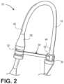
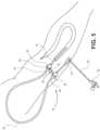
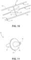
FIG. 1A is a diagrammatic isometric view illustrating an example sheath in accordance with the present disclosure.FIG. 1B is a diagrammatic isometric view illustrating another implementation of example sheath in accordance with the present disclosure, wherein the detachable curvable portion is comprised of a semi-rigid material configured to retain the desired curved configuration.FIG. 2 is a diagrammatic isometric view illustrating the sheath depicted inFIG. 1A , where the sheath is in a closed position.FIG. 3 is a diagrammatic isometric view illustrating the sheath depicted inFIG. 1A , where the sheath is in an open (i.e., unclasped) position.FIG. 4 is another diagrammatic isometric view illustrating the sheath depicted inFIG. 3 , where the sheath is in an open (i.e., unclasped) position.FIG. 5 is a diagrammatic, environmental isometric view illustrating the sheath inFIG. 1A , where a shunt member is inserted into an anatomical conduit of a patient's arm.FIG. 6 is a diagrammatic, environmental isometric view illustrating two sheaths in accordance with the present disclosure, where both sheaths are inserted into one or more anatomical conduit(s) of a patient's arm.FIG. 7 is another diagrammatic, environmental isometric view illustrating the sheath as illustrated inFIG. 1A , where the sheath is inserted into an anatomical conduit of a patient.FIG. 8 is another diagrammatic, environmental isometric view illustrating the sheath as illustrated inFIG. 1A , where the sheath is inserted into an anatomical conduit of a patient.FIG. 9 is a diagrammatic, environmental isometric view illustrating another implementation of a sheath, where the curvable portion is in a substantially straight configuration and the sheath is inserted into an anatomical conduit proximate to a patient's back side.FIG. 10 is a longitudinal cross-sectional view of an anti-backflow exchange wire utilized to prevent fluid/blood backflow when exchanging various detachable components associated with the sheath depicted inFIG. 1 .FIG. 11 is a perspective view of the septum ofFIG. 10 .- Existing sheaths are straight or have internal curves (i.e., curves within the patient). Internal curves aid in the effectiveness for certain procedures in the vascular system, but have no significant function in dialysis intervention/repair. Although effective in their purpose, existing sheaths are hampered by limitations.
- One limitation is due to the shape, flow, and direction of the permanent vascular conduit, such as an arterial-venous fistula (AVF) or arterial-venous graft (AVG). The direction of flow is from the artery to the vein, either directly or through a graft. The arterial limb of the AVF travels from proximal to distal, while the venous limb travels from distal to proximal. Therefore, access through these sheaths may occur from two separate and opposite directions, which may produce technical difficulties due to the fact that the primary operator cannot be positioned in two polar opposite directions at the same time. Treatment from one direction also can be hindered by the proximity of the sheath in relation to the rest of the patient's body impeding the ease of work.
- In addition, in order to repair AVFs via percutaneous or other minimally invasive techniques, angiography machines are required. Angiography machines utilize medical imaging techniques such as radiation to visualize the blood vessels and conduits of the patient. Radiation exposure is a concern to operators, who often perform multiple procedures in a given day. Moreover, interventional, minimally invasive repair of vascular, genitourinary tract, gastrointestinal tract, biliary, portal venous, musculoskeletal and central nervous system procedures may also expose the operator and patient to increased radiation exposure depending on technical difficulties of location of percutaneous/minimally invasive access of the conduit system of the patient in relation to the angiography machine.
- In one implementation, the present disclosure allows for improved hemodialysis access intervention, which allows for dialysis access intervention of both sides (limbs) of the dialysis conduit from the same operator position. Furthermore, the present disclosure may allow an operator, as well as the patient, to receive lower radiation exposure as well as decrease the total time of the intervention procedure.
- Therefore, a sheath with an external curvable portion is disclosed. The sheath allows for dialysis access intervention of both sides (limbs) of a dialysis conduit from the same operator position. In one or more implementations, a sheath includes a detachable shunt member, and a detachable curvable portion. The curvable portion is configured to bend between a substantially straight configuration and a curved configuration to facilitate hemodialysis intervention by an operator. In an implementation, the curvable portion may retain a 180° curve when the curvable portion is positioned in the curved configuration. In the curved configuration, the curvable portion may be held in position via a clasp. The clasp is configured to hold the curvable portion in the curved configuration. In an implementation, the clasp is coupled to at least one of a first end of the curvable portion or the second end of the curvable portion. Moreover, the clasp may be selectively coupled at a position proximate to the other of the first end of the curvable portion and the second end of the curvable portion. In yet another implementation, the curvable portion may comprise a semi-rigid material. In this implementation, the curvable portion retains its curved configuration once the operator/technician has positioned the sheath in the desired curved configuration.
- It is also contemplated that the sheath may also be comprised of detachable components. In an implementation, the shunt member may be comprised of a detachable shunt member. For example, access to an excluded aortic aneurysm with an aneurysm leak may require a longer sheath member (e.g., fifteen (15) centimeters). The detachable components may be interchangeable with other detachable components adapted for use in the sheath. Moreover, the exterior curvable portion, in conjunction with the detachable components, allows for improved operator/technician access to the patient.
- Generally referring to
FIGS. 1A through 11 , an implementation of asheath 10 configured for hemodialysis access and intervention is illustrated. Adetachable shunt member 12 may be provided with adilator 14. Thedetachable shunt member 12 is configured to extend through a perforation in a side wall, or a superficial wall, of an internal patient conduit source (e.g., a blood vessel) and into an anatomical conduit (e.g., the blood vessel) of a patient. Thedetachable shunt member 12 may vary in length depending on the use ofshunt member 12. For example, theshunt 12 may be about five (5) centimeters in length. Theshunt 12 is coupled with acurvable portion 16 by amember 18. In an implementation,member 18 may be configured as adetachable member 18.Detachable member 18 may include a septum (not shown) that is configured to receive other medical devices (i.e., needles, wire, etc.) ifdetachable curvable portion 16 is not required. In a further implementation,member 18 may be manufactured as a unitary member withshunt 12. In the unitary configuration,member 18 may include anotch 34 adapted to receiveclasp 30. In an implementation,detachable curvable portion 16 may be flexible and is capable of forming a "tennis racket" shape. In another implementation, as illustrated inFIG. 1B ,curvable portion 16 may be bendable and semi-rigid to allow thecurvable portion 16 to retain its curved configuration once an operator/technician has positioned thesheath 10 in the desired curved configuration. Thesheath 10 may be configured to be curvable or bendable between 0° and 180°. Thecurvable portion 16 may be implemented as a tube, or the like.Curvable portion 16 may form an arc having a diameter of about two (2) centimeters to about four (4) centimeters. In a specific implementation, thecurvable portion 16 may form an arc having a diameter of about three (3) centimeters. In example implementations, thesheaths 10 may be about five (5) to about eight (8) French in external diameter. However, the overall length ofsheath 10, the dimensions of the external curve ofdetachable curvable portion 16, the degree of curve ofdetachable curvable portion 16, and the length of internal (i.e., shunt 12, etc.) and external (curvable portion 16, etc.) portions ofsheath 10 can vary specific to type and location of the intervention. - A
tube 20 may be attached to aseptum hub 22 having anintroducer dilator 24 and a detachable 3-way, large bore, stopcock 26. In an implementation, the lumen (not shown) of the exposed end of thescrewable tubing 20 is comparable in size to the respective lumen of a large bore dialysis sheath.Tube 20 is utilized for injection of contrast, fluids, and medications.Tube 20 may also be utilized to aspirate clot and blood and allow for improved suction/aspiration of the thrombus/clot. In an implementation, thetube 20 is configured to have a forty-five (45) degree angle. However, it is contemplated that thetubing 20 may be implemented in various other configurations (e.g., to have different angles of curvature) without departing from the spirit of the disclosure.Septum hub 22 is configured to receive one or more interventional tools and is coupled tocurvable portion 16 by ajunction 28.Junction 28 may be coupled to aclasp 30 at ajunction 32. In one or more implementations,junction 28 may comprise a medical grade material or the like. For instance,junction 28 may be manufactured from a medical grade plastic or the like. Moreover,junction 28 is configured to stabilizecurvable portion 16.Junction 32 provides connective functionality to clasp 30. For example, clasp 30 may couple tojunction 32, which allowsclasp 30 to couple tojunction 28. WhileFIGS. 1A ,2 , and5 illustrateclasp 30 coupled to notch 34,clasp 30 may be configured to be selectively coupled to shunt 12,detachable member 18, or the like. When coupled to notch 34, or the like, clasp 30 holds the device in a position such thatseptum hub 22 is oriented in a direction opposite from that ofshunt 12 or a variation of this direction. When theclasp 30 is disengaged fromshunt 12, the flexible nature ofcurvable portion 16 allowsseptum hub 22 to be arranged generally in-line withshunt 12. In another implementation,septum hub 22 may be arranged in a variety of positions and at angles between 0° (i.e. in-line) and 180° (or possibly more if required) relative to shunt 12. In yet another implementation,septum hub 22 may be exchanged with other hub adaptors (not shown) depending on operator/technician, plumbing position, and interventional needs. Moreover, in an implementation, the detachability and interchangeability ofsheath 10 components may allow increased stiffness of the detachable curvable,external portion 16. - While
sheath 10 is shown as a complete sheath,sheath 10 could be used in conjunction with existing sheaths and sheath components. As described above,sheath 10 may also be comprised of separate, detachable components atdetachable member 18. In such implementations,sheath 10 could be used with existing components that allow for curvatures internal to the patient. For example, the internal, distal, and proximal, curved components ofsheath 10 can be interchanged with currently available sheaths if the locking systems match. In addition, existing sheath components may be used with portions ofsheath 10 to provide a sheath that may be selectively configured to provide a 180° curve. In such implementations,curvable portion 16,detachable member 18,junction 28, andclasp 30 may be provided as a single unit that would be used to retrofit an existing sheath design. - In selecting sheathing for
curvable portion 16, consideration for the largest internal diameter with a solid, kink resistant material is given. For example,curvable portion 16 may be comprised of a nitinol wire impregnated plastic sheath. Both coiled and cell design impregnated sheaths may be useful, though coil designs are likely preferable to maintain flexibility. Conventional portions of sheath may be manufactured from materials normally used for such items. When attachable/detachable components are utilized, stiffness of components may increase. - The
sheath 10 should also have an acute change in caliber at the proximal portion ofshunt 12, limiting sheath migration, as well as having anotch 34 within this diameter enlargement. Thenotch 34 may act as an attachment for aclasp 30, locking the two parallel ends of thesheath 10. Theclasp 30 will allow stability ofsheath 10 and will counter against the movements of interventional tools within thesheath 10 and internal vasculature. - As illustrated in
FIGS. 1A and2 through 4 ,clasp 30 is shown extending fromjunction 28 where it is coupled atjunction 32.Clasp 30 comprises ashank portion 40 and a claspingportion 42. In an implementation, the claspingportion 42 may have a generally arcuate configuration or the like. Claspingportion 42 extends at least partially aboutdetachable member 18 and may engagenotch 34 to securesheath 10 in a "closed" (i.e., curved) configuration. In this sense, the "closed" configuration is one in whichseptum hub 22 is oriented in a direction generally opposed to the direction ofshunt 12 andclasp 30 engagesdetachable member 18. Moreover, when thesheath 10 is in the "closed" configuration,first end 44 of thecurvable portion 16 is proximate tosecond end 46 of thecurvable portion 16. This configuration allows an operator or technician to access a vascular conduit throughsheath 10, and, in those situations where the vascular conduit may be accessed from a position proximate to the patient's torso, head, or abdomen, the operator may be positioned away from those parts of the patient. - Referring to
FIGS. 3 and 4 ,sheath 10 is in an "open" position whereclasp 30 is disengaged fromdetachable member 18. While it is shown that the "open" position may be semi-curved, it is understood that thecurvable portion 16 may retain a substantially straight configuration. For example, thecurvable portion 16 may be positioned by an operator so that thecurvable portion 16 retains a substantially straight configuration. In the substantially straight configuration, thefirst end 44 may be linearly distal to thesecond end 46. Moreover,member 48 ofsheath 10 proximate toseptum hub 22 may be more freely manipulated by an operator or technician due to the flexibility ofcurvable portion 16. For example,sheath 10 may be used in a position that places the flow atseptum hub 22 perpendicular to that of shunt 12 (as illustrated inFIG. 4 ), which allows the operator or technician to utilize an angiography machine to visualize vascular structures in the patient while the operator or technician remains outside the radiation field produced by the angiography machine. Thesheath 10 may eliminate or reduce possible exposure of the operator or technician to radiation, while allowing for the simultaneous use of tools that may be inserted throughseptum hub 22 to access the vascular conduit within the patient. FIGS. 5 through 9 illustrate one or more sheath(s) 10 utilized in a medical environment. For example, thesheath 10 disclosed herein may be readily useable in hemodialysis intervention. Other potential uses include antegrade percutaneous arterial intervention of the common femoral artery, or similar accessible vessel, whereby an operator can work along side of extremity without working near a patient's abdomen, chest, and head. Moreover, thesheath 10 may also be useful for treatment of renal collecting system intervention. Thesheath 10 also has potential for patients with ureteral strictures, status post cystectomy, and in urinary conduit formation. Moreover,sheath 10 may be utilized in conjunction with the treatment of the biliary tree, portal venous system, gastrointesintal tract, and spinal canal/thecal sac.- Additional uses for the
sheath 10 may be realized with the addition of exhalable or detachable appendages. For example, alarger curvable portion 16 may be used for larger patients receiving lower extremity intervention. Other adaptations include the use of a Toughey-Borst fitting to allow the simultaneous introduction of a fluid while using a guide wire during catheterization. A double lumen or bifurcated sheath may be used for therapy requiring two wires and access sites, from one approach. A larger internal diameter may be used to create larger communication for a suction thrombectomy. - In some implementations, a kit may comprise a single sterile prepackaged assortment of sheath components. Such kits may include a plurality of
curvable portions 16 being of different lengths and/or diameters to allow for the physician to customize thesheath 10 for a particular patient or procedure. For example, alonger curvable portion 10 may be used to facilitate antegrade access to the femoral artery for peripheral vascular disease treatment of the ipsilateral extremity, and give the physician the ability to position him/herself in the area of the patient's legs rather than by the patient's abdomen. Thelonger curvable portion 16 may be curved around the patient's leg and towards the feet to provide the physician and patient with greater comfort during a procedure. - In some implementations, a kit may include a portion of sheath configured to provide an arcuate portion (similar to curvable portion 16) with conventional couplers. The kit would allow for the modification of existing sheaths to an adjustable sheath with the ability to provide a bend of about 180°. For example, the arcuate portion may be configured to couple to an inductor (not shown) of an existing sheath (not shown). Moreover, the kit would allow an interventionist to modify a sheath system after placement in the patient if it is decided that a curved sheath would be advantageous.
- While
sheath 10 is in use, the physician or other operator may exert force to advance a catheter, needle, guide wire, or other device through thesheath 10. When thesheath 10 is arranged into a 180° curve, this force acts to pull the sheath out of the patient at the access point. Accordingly, it would be advantageous to provide a stabilizing means forsheath 10 while in use. Such a means may include an adhesive patch (not shown) for securing the sheath to the patient at a point proximate to the access point. Such patches include the STATLOCK available from C.R. BARD INC. of Murray Hill, New Jersey. Other stabilization devices may include external devices such as stabilizing boards that are coupled to the patient andsheath 10 by straps, clasps or other conventional coupling means.Sheath 10 may also be provided with a stabilizing portion that includes apertures for the placement of sutures to securesheath 10 to the patient. Sheath 10 may further include an anti-backflow exchange wire, which is illustrated inFIGS. 10 and 11 . The anti-backflow exchange wire is configured to block backflow that may occur when an operator/technician removes back end components ofsheath 10. Thus, an operator/technician may interchange the sheath's 10 back end components (e.g. converting from a straight, short 5 cm sheath, to a 180 degree curved, tennis racket shaped sheath, and so forth) with minimal to no leakage when utilizing the anti-backflow exchange wire. A septum (e.g., a valve or seal) may attach to the wire (such as a 0.4572 mm (0.018 inch) or a 0.889 mm (0.035 inch) wire) and configured to block flow within thesheath 10. The septum may be configured to move withinsheath 10 while maintaining a seal against the interior wall ofsheath 10. The septum may be fixed in relation to the wire. In use the septum moves with the wire as it is advanced through the sheath and prevent the backflow of blood or other fluids. When the wire is retracted, the septum moves with the wire. This can be done to allow completion of a procedure while minimizing the release of fluids throughsheath 10 out of the patient that could obscure the view of the operator or cause couplings to become stuck. Moreover,sheath 10 may be used with a variety of catheterization devices including guide wires.- Referring to
FIGS. 10 and 11 ,sheath section 50 has anexterior wall 52 and aninterior wall 54.Septum 56 is sized to seal the interior diameter ofsheath section 50 while allowingseptum 56 to slide relative tointerior wall 54.Septum 56 includes adisc portion 58 and twolugs Lugs longitudinal aperture 66 for receivingwire 64.Disc 58 may have an aperture coaxial withaperture 66.Disc 58 may also be punctured whenwire 64 is passed through theaperture 60 throughlugs Lugs disc 58.Lugs disc 58 may also be formed as a single unitary body to provideseptum 56.Wire 64 may be passed throughseptum 58 prior to placingseptum 56 insheath section 50. The friction betweenwire 64 andseptum 56 may be sufficiently greater than the friction betweenseptum 56 andinterior wall 54 such that onceseptum 56 is placed insheath section 50, the force required to moveseptum 56 relative tointerior wall 54 is greater than the force required to movewire 64 relative toseptum 56.Lugs passage 66 provide a greatly increased surface area over which septum 56contacts wire 64 compared to the contact area provided bydisc 58. Such a configuration allowsseptum 56 to move withinsheath section 50 while remaining static with respect towire 64 and maintaining a seal against the backflow of fluids. - Although a few implementations have been shown and described, the present disclosure is not limited to the described implementations. Instead, it would be appreciated by those skilled in the art that changes may be made to these implementations without departing from the scope of the invention, the scope of which is defined by the claims.
Claims (9)
- A sheath (10) comprising:a detachable shunt member (12) comprising a coupling member (18), the detachable shunt member (12) configured to extend through a perforation in a side wall of an internal patient conduit source and into an anatomical conduit;a detachable junction (28) configured to receive an interventional tool;a curvable portion (16) havinga first end (44) configured to be detachably coupled to the coupling member (18) of the detachable shunt member (12) anda second end (46) configured to be detachably coupled to the detachable junction (28),wherein the curvable portion (16) is configured to bend between a curved configuration and a substantially straight configuration where the first end (44) is linearly distal to the second end (46);a septum hub (22) configured to be detachably coupled to the second end of the curvable portion (16) by the detachable junction (28), wherein the septum hub (22) is configured to receive the interventional tool inserted therethrough allowing the interventional tool to be advanced through the sheath (10) to access the anatomical conduit.
- The sheath as recited in claim 1, wherein the member (18) includes a septum.
- The sheath as recited in claim 1, wherein the curvable portion (16) is configured to form up to an 180° curve when the curvable portion (16) is in the curved configuration.
- The sheath as recited in claim 1, wherein the curvable portion (16) is comprised of a semirigid material and is configured to retain a desired curved configuration.
- The sheath as recited in claim 1, further comprising:
a clasp (30) configured to hold the curvable portion (16) in the curved configuration. - The sheath as recited in claim 4, wherein the clasp (30) is configured to counter against the movements of interventional tool.
- The sheath as recited in claim 1, comprising a stabilization means for securing the sheath to the patient at a point proximate the perforation while an interventional tool is advanced through the sheath into the anatomical conduit.
- The sheath as recited in claim 6, wherein the stabilization means comprises an adhesive patch.
- The sheath as recited in claim 1, wherein the septum hub (22) includes an introducer portion (24) and a tube (20) for injecting or suctioning fluids.
Applications Claiming Priority (2)
| Application Number | Priority Date | Filing Date | Title |
|---|---|---|---|
| US28640809P | 2009-12-15 | 2009-12-15 | |
| PCT/US2010/060556WO2011084505A2 (en) | 2009-12-15 | 2010-12-15 | Sheath |
Publications (4)
| Publication Number | Publication Date |
|---|---|
| EP2512583A2 EP2512583A2 (en) | 2012-10-24 |
| EP2512583A4 EP2512583A4 (en) | 2013-12-11 |
| EP2512583B1true EP2512583B1 (en) | 2025-04-23 |
| EP2512583C0 EP2512583C0 (en) | 2025-04-23 |
Family
ID=44306036
Family Applications (1)
| Application Number | Title | Priority Date | Filing Date |
|---|---|---|---|
| EP10842550.5AActiveEP2512583B1 (en) | 2009-12-15 | 2010-12-15 | Sheath |
Country Status (5)
| Country | Link |
|---|---|
| US (5) | US8911396B2 (en) |
| EP (1) | EP2512583B1 (en) |
| AU (1) | AU2010340025B2 (en) |
| CA (2) | CA2818960C (en) |
| WO (1) | WO2011084505A2 (en) |
Families Citing this family (9)
| Publication number | Priority date | Publication date | Assignee | Title |
|---|---|---|---|---|
| CA2818960C (en) | 2009-12-15 | 2018-11-13 | The Board Of Regents Of The University Of Nebraska | Sheath |
| US20190015635A1 (en) | 2011-05-09 | 2019-01-17 | SimplicityMD Solutions, LLC | Catheter securement device and related methods |
| JP5925093B2 (en) | 2012-02-10 | 2016-05-25 | テルモ株式会社 | Direction changing device and medical device assembly including the same |
| EP3777956B1 (en) | 2013-10-15 | 2024-06-12 | Radux Devices, LLC | Securing a medical device to a valve instrument |
| USD809136S1 (en)* | 2014-09-17 | 2018-01-30 | Kirwan Surgical Products Llc | Electrical connector and irrigation connector for irrigation cord assembly |
| US10099037B2 (en)* | 2015-09-15 | 2018-10-16 | Radux Devices, LLC | Sheath retainer devices, systems and methods |
| US10556094B2 (en) | 2017-03-15 | 2020-02-11 | Radux Devices, LLC | Interventional tool delivery devices, systems and methods |
| ES2811175A1 (en)* | 2019-09-10 | 2021-03-10 | Corpas Miguel Angel Penalba | FIXING DEVICE FOR PERIPHERAL VENOUS CATHETER |
| WO2022021174A1 (en)* | 2020-07-30 | 2022-02-03 | Fresenius Medical Care Deutschland Gmbh | Connector for securing medical tubes |
Citations (1)
| Publication number | Priority date | Publication date | Assignee | Title |
|---|---|---|---|---|
| US5902274A (en)* | 1996-08-02 | 1999-05-11 | Nissho Corporation | Catheter assembly |
Family Cites Families (80)
| Publication number | Priority date | Publication date | Assignee | Title |
|---|---|---|---|---|
| US3630195A (en)* | 1970-02-04 | 1971-12-28 | Deseret Pharma | Infusion tube holder and method |
| US3897923A (en)* | 1971-12-13 | 1975-08-05 | Ball Corp | Curvature maintaining device |
| US3853126A (en) | 1973-11-15 | 1974-12-10 | Heyer Schulte Corp | Artery-to-vein shunt |
| US3998222A (en) | 1974-04-15 | 1976-12-21 | Shihata Alfred A | Subcutaneous arterio-venous shunt with valve |
| US3942528A (en)* | 1974-07-18 | 1976-03-09 | Loeser Edward A | Non-kinking intravenous tube loop device |
| US4029103A (en)* | 1975-08-11 | 1977-06-14 | Mcconnell Francis P | Anchoring plate for medical tubes |
| US4027668A (en)* | 1975-12-10 | 1977-06-07 | Dunn Allan R | Multi-angle U-shaped hub for infusion member |
| US4316461A (en)* | 1977-02-22 | 1982-02-23 | Marais Henri J | Intravenous vascular stabilizer |
| BE887056Q (en)* | 1979-01-19 | 1981-05-04 | Whitman Med Corp | STABILIZATION MOUNT FOR AN INTRAVENOUS CATHETER |
| US4345616A (en)* | 1980-03-17 | 1982-08-24 | Terry Paul V | Retractor for hose-connected hand pieces |
| US4397641A (en)* | 1981-04-03 | 1983-08-09 | Jacobs Daimon C | Catheter support device |
| US4406042A (en)* | 1981-04-13 | 1983-09-27 | American Hospital Supply Corporation | Tubing clip |
| US4453933A (en)* | 1981-11-24 | 1984-06-12 | Speaker Mark G | Intravenous device |
| US4568338A (en)* | 1983-09-22 | 1986-02-04 | C. R. Bard, Inc. | Preformed catheter |
| US4585435A (en)* | 1984-05-31 | 1986-04-29 | The Telescope Folding Furniture Co., Inc. | Extension set for drug delivery |
| US4606735A (en)* | 1984-09-24 | 1986-08-19 | Wilder Joseph R | Medical tubing holder |
| FR2587219B1 (en) | 1985-09-16 | 1987-12-18 | Charvin Guy | CONNECTION DEVICE FOR EXTRA-BODY CIRCULATION CIRCUIT |
| US4865586A (en)* | 1987-09-21 | 1989-09-12 | Martha Hedberg | Suction stylet for endotracheal intubation |
| US4976698A (en)* | 1987-10-23 | 1990-12-11 | Stokley Manuel H | Intravenous catheter and tubing stabilization device |
| US4840613A (en)* | 1988-04-27 | 1989-06-20 | Menlo Care, Inc. | Protective sheath for catheter assembly |
| US5702371A (en)* | 1989-07-24 | 1997-12-30 | Venetec International, Inc. | Tube fitting anchoring system |
| US5031775A (en)* | 1990-02-14 | 1991-07-16 | Angeion Corporation | Medical instrument holder |
| US5489274A (en)* | 1992-10-09 | 1996-02-06 | Boston Scientific Corporation | Rotatable medical valve closure |
| US6663599B2 (en)* | 1992-05-06 | 2003-12-16 | Cook Incorporated | Hemostasis cannula |
| US5267969A (en)* | 1992-10-08 | 1993-12-07 | Abbott Laboratories | External retaining device for feeding tube or the like |
| JP3310031B2 (en)* | 1992-10-23 | 2002-07-29 | テルモ株式会社 | Catheter tube |
| US5342325A (en)* | 1992-12-07 | 1994-08-30 | Dlp, Incorporated | Introducer needle and catheter assembly |
| US6161543A (en)* | 1993-02-22 | 2000-12-19 | Epicor, Inc. | Methods of epicardial ablation for creating a lesion around the pulmonary veins |
| US5443460A (en)* | 1993-06-10 | 1995-08-22 | Miklusek; John M. | Non-kinking tubing adaptor for intravenous catheter and associated flexible tubing |
| US5407434A (en)* | 1994-01-27 | 1995-04-18 | The Kendall Company | Automatic lumen viscous reseal |
| US5647859A (en)* | 1994-02-18 | 1997-07-15 | Merit Medical Systems, Inc. | Catheter apparatus with means for subcutaneous delivery of anesthetic agent or other fluid medicament |
| US7033339B1 (en)* | 1998-05-29 | 2006-04-25 | Becton Dickinson And Company (Part Interest) | Self sealing luer receiving stopcock |
| US6077243A (en)* | 1996-01-11 | 2000-06-20 | C.R. Bard, Inc. | Retention balloon for a corporeal access tube assembly |
| US5843002A (en)* | 1996-06-10 | 1998-12-01 | Baxter International Inc. | Guide wire dispenser apparatus and method |
| US5916199A (en)* | 1996-07-11 | 1999-06-29 | Miles; John E. | Tapeless tubing anchoring system with intravenous applications |
| US6001081A (en)* | 1997-09-02 | 1999-12-14 | Dionex Corp. | Kink inhibiting device |
| US6743218B2 (en)* | 1999-01-15 | 2004-06-01 | Cathlogic, Inc. | Retractable catheter systems and associated methods |
| US6258066B1 (en)* | 1999-03-08 | 2001-07-10 | Rex W. Urich | Intravenous catheter stabilizing device |
| US6682505B2 (en)* | 1999-03-12 | 2004-01-27 | Arteria Medical Science, Inc. | Catheter for removing emboli from saphenous vein grafts and native coronary arteries |
| US6179828B1 (en)* | 1999-03-19 | 2001-01-30 | Merit Medical Systems, Inc. | Infusion system with fixed occluding wire |
| US6113577A (en)* | 1999-04-23 | 2000-09-05 | Canox International, Ltd. | Intravascular access device positioning system |
| US6471676B1 (en)* | 2000-03-21 | 2002-10-29 | Novartis Nutrition Ag | Catheter and feeding tube retention device and method of use |
| US6699221B2 (en)* | 2000-06-15 | 2004-03-02 | Vincent L. Vaillancourt | Bloodless catheter |
| US7571744B2 (en)* | 2001-01-31 | 2009-08-11 | Hemerus Medical, Llc | Multi-purpose tubing apparatus |
| US6821263B2 (en)* | 2001-06-28 | 2004-11-23 | Jay A. Lenker | Method and apparatus for venous drainage and retrograde coronary perfusion |
| US6638253B2 (en)* | 2001-07-17 | 2003-10-28 | Eugene Michael Breznock | Method and apparatus for chest drainage |
| EP1439880A1 (en)* | 2001-10-23 | 2004-07-28 | Novarix Ltd. | A device for supporting and stabilising a tubing for fluid transport and such a tubing |
| TW564489B (en) | 2002-07-25 | 2003-12-01 | Toppoly Optoelectronics Corp | Method for improving contact hole patterning |
| WO2004034767A2 (en)* | 2002-09-20 | 2004-04-29 | Flowmedica, Inc. | Catheter system for renal therapy |
| FR2847799B1 (en)* | 2002-11-28 | 2005-02-25 | Maxime Formichi | DEVICE FOR ENDOVASCULAR SURGERY |
| US7166088B2 (en)* | 2003-01-27 | 2007-01-23 | Heuser Richard R | Catheter introducer system |
| US20040186461A1 (en)* | 2003-03-17 | 2004-09-23 | Dimatteo Kristian | Catheter with an adjustable cuff |
| US7544184B2 (en)* | 2003-04-04 | 2009-06-09 | Cook Incorporated | Bloodless percutaneous insertion system |
| US20060129091A1 (en)* | 2004-12-10 | 2006-06-15 | Possis Medical, Inc. | Enhanced cross stream mechanical thrombectomy catheter with backloading manifold |
| US7951115B2 (en)* | 2003-10-14 | 2011-05-31 | Altman Sanford D | Safety dialysis needle/catheter system and method of use |
| US7553326B2 (en) | 2003-11-24 | 2009-06-30 | Sweet Richard M | Method and apparatus for preventing dialysis graft intimal hyperplasia |
| US20050165364A1 (en)* | 2004-01-22 | 2005-07-28 | Dimatteo Kristian | Valved catheter to bypass connector |
| US8083728B2 (en)* | 2004-03-18 | 2011-12-27 | C. R. Bard, Inc. | Multifunction adaptor for an open-ended catheter |
| US20050234405A1 (en)* | 2004-04-16 | 2005-10-20 | Dikeman W C | Site securement device for securing intravascular tubing |
| US7678081B2 (en)* | 2004-07-12 | 2010-03-16 | Pacesetter, Inc. | Methods and devices for transseptal access |
| US7678083B2 (en)* | 2004-08-25 | 2010-03-16 | Medical Components, Inc. | Pre-curved catheter tip |
| US8029470B2 (en)* | 2004-09-30 | 2011-10-04 | Pacesetter, Inc. | Transmembrane access systems and methods |
| US7258685B2 (en)* | 2004-11-29 | 2007-08-21 | Andrew Kerr | Dialysis catheter |
| US20060155247A1 (en)* | 2005-01-13 | 2006-07-13 | Lampropoulos Bryan R | Introducer sheath with rotatable stop cock |
| US20070021767A1 (en)* | 2005-07-25 | 2007-01-25 | Breznock Eugene M | Steerable endoluminal punch |
| EP1912592A4 (en)* | 2005-07-26 | 2016-01-06 | Rox Medical Inc | DEVICES, SYSTEMS AND METHODS FOR ARTERIOVINOUS FISTULA CREATION |
| US7985205B2 (en)* | 2005-09-14 | 2011-07-26 | Boston Scientific Scimed, Inc. | Medical catheter external bolster having strain relief member |
| US7621009B2 (en)* | 2005-11-16 | 2009-11-24 | Basim Elhabashy | Surgical coordinator for anesthesiologist and methods of use |
| US20070167901A1 (en)* | 2005-11-17 | 2007-07-19 | Herrig Judson A | Self-sealing residual compressive stress graft for dialysis |
| DE102006011313B3 (en)* | 2006-03-11 | 2007-05-10 | Fresenius Medical Care Deutschland Gmbh | Monitoring system for tubes connecting patient to hemodialysis machine incorporates holder which fixes section of tube in form of loop which can be tightened by pulling on one end of tube |
| US20070225680A1 (en)* | 2006-03-21 | 2007-09-27 | Medtronic Vascular, Inc. | Guiding catheter with chemically softened distal portion and method of making same |
| DE602007004718D1 (en)* | 2006-03-31 | 2010-03-25 | Bard Inc C R | Catheter with arched transition area |
| US20100081863A1 (en)* | 2008-09-30 | 2010-04-01 | Ethicon Endo-Surgery, Inc. | Methods and devices for performing gastrectomies and gastroplasties |
| SE532670C2 (en)* | 2006-04-19 | 2010-03-16 | Nordic Med Com Ab | catheter assembly |
| MY177188A (en)* | 2006-12-11 | 2020-09-09 | Medic Domain M Sdn Bhd | A device for protecting and securing medical device at a venipuncture site |
| US8425602B2 (en)* | 2007-02-09 | 2013-04-23 | Alphatec Spine, Inc. | Curvilinear spinal access method and device |
| JP5174891B2 (en)* | 2007-04-27 | 2013-04-03 | シーヴィ デヴァイシズ,エルエルシー | Devices, systems, and methods for accessing the epicardial surface of the heart |
| WO2009036413A1 (en)* | 2007-09-14 | 2009-03-19 | Medrad, Inc. | Fluid path set providing gravity flow prevention |
| IT1393665B1 (en)* | 2008-10-22 | 2012-05-08 | N G C Medical S P A | INTRODUCTION WITH BODY WITH ADJUSTABLE DIAMETER, USABLE DURING HEMODYNAMIC STUDIES AND RELATIVE INTERVENTIONS. |
| CA2818960C (en)* | 2009-12-15 | 2018-11-13 | The Board Of Regents Of The University Of Nebraska | Sheath |
- 2010
- 2010-12-15CACA2818960Apatent/CA2818960C/enactiveActive
- 2010-12-15CACA3019295Apatent/CA3019295C/enactiveActive
- 2010-12-15USUS13/516,290patent/US8911396B2/enactiveActive
- 2010-12-15WOPCT/US2010/060556patent/WO2011084505A2/enactiveIP Right Grant
- 2010-12-15EPEP10842550.5Apatent/EP2512583B1/enactiveActive
- 2010-12-15AUAU2010340025Apatent/AU2010340025B2/enactiveActive
- 2014
- 2014-12-15USUS14/570,691patent/US9585691B2/enactiveActive
- 2017
- 2017-01-27USUS15/417,395patent/US10507305B2/enactiveActive
- 2019
- 2019-11-12USUS16/681,301patent/US11420027B2/enactiveActive
- 2022
- 2022-08-22USUS17/892,377patent/US12268827B2/enactiveActive
Patent Citations (1)
| Publication number | Priority date | Publication date | Assignee | Title |
|---|---|---|---|---|
| US5902274A (en)* | 1996-08-02 | 1999-05-11 | Nissho Corporation | Catheter assembly |
Also Published As
| Publication number | Publication date |
|---|---|
| EP2512583C0 (en) | 2025-04-23 |
| US8911396B2 (en) | 2014-12-16 |
| CA3019295C (en) | 2022-04-12 |
| US12268827B2 (en) | 2025-04-08 |
| US11420027B2 (en) | 2022-08-23 |
| US20220401705A1 (en) | 2022-12-22 |
| US10507305B2 (en) | 2019-12-17 |
| WO2011084505A2 (en) | 2011-07-14 |
| US9585691B2 (en) | 2017-03-07 |
| AU2010340025B2 (en) | 2014-11-20 |
| US20200078567A1 (en) | 2020-03-12 |
| US20150112242A1 (en) | 2015-04-23 |
| EP2512583A4 (en) | 2013-12-11 |
| US20130006163A1 (en) | 2013-01-03 |
| WO2011084505A3 (en) | 2011-11-03 |
| EP2512583A2 (en) | 2012-10-24 |
| CA2818960A1 (en) | 2011-07-14 |
| CA3019295A1 (en) | 2011-07-14 |
| US20170136218A1 (en) | 2017-05-18 |
| AU2010340025A1 (en) | 2012-08-02 |
| CA2818960C (en) | 2018-11-13 |
Similar Documents
| Publication | Publication Date | Title |
|---|---|---|
| US12268827B2 (en) | Sheath | |
| US11896786B2 (en) | Catheter system and method of introducing an intravenous catheter into a patient | |
| US9713694B2 (en) | Low profile catheter assembly | |
| JP5925093B2 (en) | Direction changing device and medical device assembly including the same | |
| US20160067472A1 (en) | Catheter adapter apparatus | |
| US11766543B2 (en) | Sheath retainer devices, systems and methods | |
| US11517721B2 (en) | Interventional tool delivery devices, systems and MElHODS | |
| Fox et al. | Central venous catheters: Selection and placement techniques |
Legal Events
| Date | Code | Title | Description |
|---|---|---|---|
| PUAI | Public reference made under article 153(3) epc to a published international application that has entered the european phase | Free format text:ORIGINAL CODE: 0009012 | |
| 17P | Request for examination filed | Effective date:20120711 | |
| AK | Designated contracting states | Kind code of ref document:A2 Designated state(s):AL AT BE BG CH CY CZ DE DK EE ES FI FR GB GR HR HU IE IS IT LI LT LU LV MC MK MT NL NO PL PT RO RS SE SI SK SM TR | |
| RIN1 | Information on inventor provided before grant (corrected) | Inventor name:GORDON, GREGORY | |
| DAX | Request for extension of the european patent (deleted) | ||
| A4 | Supplementary search report drawn up and despatched | Effective date:20131113 | |
| RIC1 | Information provided on ipc code assigned before grant | Ipc:A61M 25/01 20060101ALI20131107BHEP Ipc:A61M 1/14 20060101ALI20131107BHEP Ipc:A61M 39/08 20060101AFI20131107BHEP Ipc:A61M 39/12 20060101ALI20131107BHEP | |
| 17Q | First examination report despatched | Effective date:20160419 | |
| STAA | Information on the status of an ep patent application or granted ep patent | Free format text:STATUS: EXAMINATION IS IN PROGRESS | |
| REG | Reference to a national code | Ref country code:DE Ref legal event code:R079 Ref document number:602010069730 Country of ref document:DE Free format text:PREVIOUS MAIN CLASS: A61M0039080000 Ipc:A61M0025020000 Ref country code:DE Ref legal event code:R079 Free format text:PREVIOUS MAIN CLASS: A61M0039080000 Ipc:A61M0025020000 | |
| GRAP | Despatch of communication of intention to grant a patent | Free format text:ORIGINAL CODE: EPIDOSNIGR1 | |
| STAA | Information on the status of an ep patent application or granted ep patent | Free format text:STATUS: GRANT OF PATENT IS INTENDED | |
| RIC1 | Information provided on ipc code assigned before grant | Ipc:A61M 39/08 20060101ALI20241102BHEP Ipc:A61M 25/01 20060101ALI20241102BHEP Ipc:A61M 39/00 20060101ALI20241102BHEP Ipc:A61M 25/06 20060101ALI20241102BHEP Ipc:A61M 25/02 20060101AFI20241102BHEP | |
| INTG | Intention to grant announced | Effective date:20241114 | |
| GRAS | Grant fee paid | Free format text:ORIGINAL CODE: EPIDOSNIGR3 | |
| GRAA | (expected) grant | Free format text:ORIGINAL CODE: 0009210 | |
| STAA | Information on the status of an ep patent application or granted ep patent | Free format text:STATUS: THE PATENT HAS BEEN GRANTED | |
| AK | Designated contracting states | Kind code of ref document:B1 Designated state(s):AL AT BE BG CH CY CZ DE DK EE ES FI FR GB GR HR HU IE IS IT LI LT LU LV MC MK MT NL NO PL PT RO RS SE SI SK SM TR | |
| REG | Reference to a national code | Ref country code:GB Ref legal event code:FG4D | |
| REG | Reference to a national code | Ref country code:CH Ref legal event code:EP | |
| REG | Reference to a national code | Ref country code:DE Ref legal event code:R096 Ref document number:602010069730 Country of ref document:DE | |
| REG | Reference to a national code | Ref country code:IE Ref legal event code:FG4D | |
| U01 | Request for unitary effect filed | Effective date:20250523 | |
| U07 | Unitary effect registered | Designated state(s):AT BE BG DE DK EE FI FR IT LT LU LV MT NL PT RO SE SI Effective date:20250620 | |
| PG25 | Lapsed in a contracting state [announced via postgrant information from national office to epo] | Ref country code:ES Free format text:LAPSE BECAUSE OF FAILURE TO SUBMIT A TRANSLATION OF THE DESCRIPTION OR TO PAY THE FEE WITHIN THE PRESCRIBED TIME-LIMIT Effective date:20250423 |