EP2511993B1 - System for connecting motor drives - Google Patents
System for connecting motor drivesDownload PDFInfo
- Publication number
- EP2511993B1 EP2511993B1EP12164208.6AEP12164208AEP2511993B1EP 2511993 B1EP2511993 B1EP 2511993B1EP 12164208 AEP12164208 AEP 12164208AEP 2511993 B1EP2511993 B1EP 2511993B1
- Authority
- EP
- European Patent Office
- Prior art keywords
- bus bar
- clip
- connector system
- cover
- bus
- Prior art date
- Legal status (The legal status is an assumption and is not a legal conclusion. Google has not performed a legal analysis and makes no representation as to the accuracy of the status listed.)
- Active
Links
Images


Classifications
- H—ELECTRICITY
- H01—ELECTRIC ELEMENTS
- H01R—ELECTRICALLY-CONDUCTIVE CONNECTIONS; STRUCTURAL ASSOCIATIONS OF A PLURALITY OF MUTUALLY-INSULATED ELECTRICAL CONNECTING ELEMENTS; COUPLING DEVICES; CURRENT COLLECTORS
- H01R13/00—Details of coupling devices of the kinds covered by groups H01R12/70 or H01R24/00 - H01R33/00
- H01R13/44—Means for preventing access to live contacts
- H—ELECTRICITY
- H01—ELECTRIC ELEMENTS
- H01R—ELECTRICALLY-CONDUCTIVE CONNECTIONS; STRUCTURAL ASSOCIATIONS OF A PLURALITY OF MUTUALLY-INSULATED ELECTRICAL CONNECTING ELEMENTS; COUPLING DEVICES; CURRENT COLLECTORS
- H01R13/00—Details of coupling devices of the kinds covered by groups H01R12/70 or H01R24/00 - H01R33/00
- H01R13/46—Bases; Cases
- H01R13/514—Bases; Cases composed as a modular blocks or assembly, i.e. composed of co-operating parts provided with contact members or holding contact members between them
- H—ELECTRICITY
- H01—ELECTRIC ELEMENTS
- H01R—ELECTRICALLY-CONDUCTIVE CONNECTIONS; STRUCTURAL ASSOCIATIONS OF A PLURALITY OF MUTUALLY-INSULATED ELECTRICAL CONNECTING ELEMENTS; COUPLING DEVICES; CURRENT COLLECTORS
- H01R31/00—Coupling parts supported only by co-operation with counterpart
- H01R31/08—Short-circuiting members for bridging contacts in a counterpart
- H01R31/085—Short circuiting bus-strips
- H—ELECTRICITY
- H01—ELECTRIC ELEMENTS
- H01R—ELECTRICALLY-CONDUCTIVE CONNECTIONS; STRUCTURAL ASSOCIATIONS OF A PLURALITY OF MUTUALLY-INSULATED ELECTRICAL CONNECTING ELEMENTS; COUPLING DEVICES; CURRENT COLLECTORS
- H01R9/00—Structural associations of a plurality of mutually-insulated electrical connecting elements, e.g. terminal strips or terminal blocks; Terminals or binding posts mounted upon a base or in a case; Bases therefor
- H01R9/22—Bases, e.g. strip, block, panel
- H01R9/24—Terminal blocks
- H01R9/26—Clip-on terminal blocks for side-by-side rail- or strip-mounting
- H01R9/2675—Electrical interconnections between two blocks, e.g. by means of busbars
- H—ELECTRICITY
- H01—ELECTRIC ELEMENTS
- H01R—ELECTRICALLY-CONDUCTIVE CONNECTIONS; STRUCTURAL ASSOCIATIONS OF A PLURALITY OF MUTUALLY-INSULATED ELECTRICAL CONNECTING ELEMENTS; COUPLING DEVICES; CURRENT COLLECTORS
- H01R13/00—Details of coupling devices of the kinds covered by groups H01R12/70 or H01R24/00 - H01R33/00
- H01R13/46—Bases; Cases
- H01R13/52—Dustproof, splashproof, drip-proof, waterproof, or flameproof cases
- H01R13/5213—Covers
- H—ELECTRICITY
- H01—ELECTRIC ELEMENTS
- H01R—ELECTRICALLY-CONDUCTIVE CONNECTIONS; STRUCTURAL ASSOCIATIONS OF A PLURALITY OF MUTUALLY-INSULATED ELECTRICAL CONNECTING ELEMENTS; COUPLING DEVICES; CURRENT COLLECTORS
- H01R9/00—Structural associations of a plurality of mutually-insulated electrical connecting elements, e.g. terminal strips or terminal blocks; Terminals or binding posts mounted upon a base or in a case; Bases therefor
- H01R9/22—Bases, e.g. strip, block, panel
- H01R9/24—Terminal blocks
- H01R9/2458—Electrical interconnections between terminal blocks
- H—ELECTRICITY
- H02—GENERATION; CONVERSION OR DISTRIBUTION OF ELECTRIC POWER
- H02B—BOARDS, SUBSTATIONS OR SWITCHING ARRANGEMENTS FOR THE SUPPLY OR DISTRIBUTION OF ELECTRIC POWER
- H02B13/00—Arrangement of switchgear in which switches are enclosed in, or structurally associated with, a casing, e.g. cubicle
- H02B13/005—Electrical connection between switchgear cells
- H—ELECTRICITY
- H02—GENERATION; CONVERSION OR DISTRIBUTION OF ELECTRIC POWER
- H02G—INSTALLATION OF ELECTRIC CABLES OR LINES, OR OF COMBINED OPTICAL AND ELECTRIC CABLES OR LINES
- H02G5/00—Installations of bus-bars
- H02G5/10—Cooling
Definitions
- the subject matter disclosed hereinrelates to electrical conductors that connect electronic components to each other and, more particularly, to wiring systems for connecting servo motor drives to each other within servo motor drive systems.
- Servomotorsprovide a motor coupled to a sensor, for example, a position sensor such as an encoder, so that feedback control of the motor may be provided, for example, precise positioning control.
- a servo motor drive systemprovides a servo motor, for example, a DC permanent magnet motor and position encoder, which is wired to a servo drive.
- the servo driveprovides a controllable source of DC power as controlled by a feedback signal from the position encoder by, for example, using a PID (proportional-integral-derivative) motor control algorithm.
- PIDproportional-integral-derivative
- the servo drivemay be installed in an equipment cabinet to receive the source of DC power.
- this source of DC poweris independently wired to each of the servo drives, for example, using terminal blocks and/or standard electrical connectors with pins or blades engaging corresponding sockets. Power has been delivered to printed circuit boards through bus bars that engage connectors that are soldered or screwed to the printed circuit boards.
- German patent application publication DE 10 2009 003534 A1describes an electric cross-connector, and, in particular, an end cap therefor, which covers and isolates free ends of a contact strip.
- the cross-connectorhas comb-shaped contacts formed at the contact strip and locked in plug-in openings of bus bars of series terminals.
- European Patent Application EP 1 291 977 A2describes an electrical connection system between modules, which comprises a conductive piece and an insulating piece housing the conductive piece.
- the conductive piecehas free ends not covered by the housing, for being connected with other modules.
- Document FR 2 818 021 A1describes a connection system, wherein a bus bar contacting metallic portions of electronic components is received in insulating receptacles for electric protection.
- the inventorshave recognized that wiring electronic components such as, for example, motor drives to each other can take substantial amounts of time.
- the inventorshave also recognized that different end-use implementations of industrial controls may require highly skilled technicians to assemble motor drives because such end-use implementations tend to differ from each other and may require, for example, using numerous conductors that have to be cut to length to make numerous wire-based "daisy-chain" -type or other sequential connections to interconnect the motor drives.
- bus bar based connecting systemstypically include bus bar receptacles that have to be soldered or screwed to printed circuit boards, which may take substantial amounts of time to install.
- bus bars of such connecting systemspresent exposed conductive surfaces having relatively large surface areas and that are in locations of motor drive housings that may be subjected to airborne particulate matter which may dirty the electrical contacts and compromise conductivity, and that bus bars of such connecting systems may also be in locations of motor drives housings that may be accessed later by technicians with tools, which may inadvertently produce short circuit conditions by contacting the exposed bus bars.
- the present inventioncontemplates a bus bar connector system that addresses various ones of these and other inventor-identified problems and drawbacks of known systems. This is achieved by the features of claim 1.
- a bus bar connector systemfor removably connecting at least two electronic components to each other.
- the systemmay include a bus bar module having a bus bar with a first blade having a first exposed conductive surface(s) for connecting to a first electronic component and a second blade having a second exposed conductive surface(s) for connecting to a second electronic component.
- the bus barmay have a covered segment that extends between the first and second blades.
- An insulating covermay be connected to the bus bar and extend over the covered segment of the bus bar.
- a clipmay engage the bus bar module and be movable between at least first and second positions.
- the clipWhen the clip is in the first position, it may overlie at least one of the first and second blades or exposed conductive surfaces of the bus bar. When the clip is in the second position, it may be spaced from the first and/or second blades or exposed conductive surfaces of the bus bar. This may allow conductors within the bus bar connector system to be covered or non-exposed.
- the insulating covermay include a pair of opposing side walls that extend over a pair of opposing side walls of the bus bar module.
- the clip side wallsmay slidingly engage the insulating cover side walls so that the clip can move longitudinally with respect to the bus bar module while being transversely guided upon the bus bar module. This may allow conductors within the bus bar connector system to be covered quickly during assembly.
- the bus bar connector systemincludes first and second bus bar modules.
- the first and second bus bar modulesmay be connected to each other at a splice joint.
- the splice jointmay include a conductive receptacle that holds respective ends of the first and second bus bar modules, so that their blades or exposed conductive surfaces contact the conductive receptacle so as to electrically connect the first and second bus bar modules to each other.
- the clipmay cover the splice joint so that the covered surfaces of the bus bars of the first and second bus bar modules and the clip define a continuously covered length of the combination of the first and second bus bar modules and splice joint. This may allow bus bars to be quickly coupled to or uncoupled from each other which may facilitate connecting electronic components to each other while providing a connector system that has its conductive surfaces substantially covered with insulating materials.
- the conductive receptaclemay be provided in a plug housing of an adapter plug.
- the conductive receptaclemay be provided at a first end of the adapter plug and a second end of the adapter plug may be operably coupled to a connector that is fixed to a printed circuit board of an electronic device. This may facilitate quickly connecting electronic devices to each other.
- the clipmay be slidably mounted to the first bus bar module and may be slidable over the plug housing and upon the second bus bar module, so that the clip covers the entire splice joint and overlaps portions of the first and second bus bar modules.
- a lockmay be provided that prevents sliding movement of the clip with respect to the splice joint.
- the lockmay include a lock projection and a cooperating lock receptacle on the clip and at least one of the adapter plug and first and second bus bar modules, which can engage each other to secure the clip in place when it covers the splice joint. This may allow the clip to remain in a position in which it covers the splice joint that connects bus bars to each other so that conductive materials of the splice joint remain unexposed or substantially covered with insulating materials.
- each bus bar modulemay include a pair of bus bars that are transversely spaced and electrically insulated from each other.
- Each adapter plugmay include a pair of connective receptacles that are transversely spaced from and insulated with respect to each other. This may facilitate simultaneously connecting positive and negative bus bars to electronic components which may simplify connecting such electronic components to each other by allowing multiple connections to be made in a single installation step.
- the bus bar connector systemmay be implemented within an industrial control system and may connect multiple motor drives to each other.
- First, second, and third adapter plugsmay be connected to first, second, and third motor drives of the industrial control system.
- a pair of bus bar modulesmay be longitudinally aligned with each other so that outer ends of the bus bar modules are connected to the first and third adapter plugs.
- Inner or inwardly positioned ends of the bus bar modulesmay be connected to each other at a spliced joint defined at the second adapter plug and a clip may extend over the splice joint.
- the bus bar connector systemmay include the same number of adapter plugs as the number of motor drives that are being connected and may include one fewer bus bar module than the number of motor drives and adapter plugs. This may facilitate connecting multiple motor drives to each other in a tool-less manner.
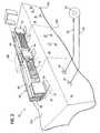
- a bus bar connector system 30is a modular system that electronically connects at least two, while allowing for connecting an arbitrary number of, electronic components to each other in a tool-less manner.
- the bus bar connector system 30is described as being used in a servo motor drive system 10 to simplify its explanation, while noting that the bus bar connector system 30 in other embodiments may be implemented to interconnect various other electronic components to each other.
- a servo motor drive system 10may provide for multiple drive modules 12a-12c each having generally rectangular housings 14 that may be mounted in a control cabinet or the like to be in side-by-side adjacent relationship with respect to each other.
- Rear vertical walls 16 of the housings 14may include openings through which connectors 18 are accessible and to which power conductors 20 and signal conductors 22 may be connected.
- Power conductors 20may deliver electrical power to windings of a servomotor 25 for energizing the servomotor.
- Signal conductors 22may convey control signals between an encoder of the servomotor 25 and the drive modules 12a-12c so that the drive modules 12a-12c may control the servomotor 22 according to methods well known in the art.
- horizontal upper walls 26 of the drive modules housings 14 of this embodimentmay present socket receptacles 28 of electrical connectors 27 that are flush mounted with the upper walls 26 of the drive modules 12a-12c.
- the electrical connectors 27are operably connected to printed circuit boards of the drive modules 12a-12c for delivering electrical power to the drive modules 12a-12c.
- a bus bar connector system 30is a modular system that interconnects the drive modules 12a-12c by wire-free daisy chain connections that can provide main power and/or control power to the drive modules 12a-12c.
- the main poweris 100 amp DC bus power and the control power is 16 amp, 24 volt control power, optionally, other values of main and control power, depending on the particular configurations of the drive modules 12a-12c.
- the modular configuration of the bus bar connector system 30allows for drive modules 12a-12c to be added to or removed from the servo motor drive system 10, while making or removing the electrical interconnections between the drive modules 12a-12c in a tool-less manner.
- the bus bar connector system 30includes adapter plugs 40,41 and bus bar modules 70, 71 that cooperate with each other to make the tool-less electrical connections between the drive modules 12a-12c.
- Multiple adapter plugs 40, 41 and multiple bus bar modules 70, 71may be provided within the bus bar connector system 30 so that an arbitrary number of parallel electrical conductive paths through chains of the bus bar modules 70, 71 in a manner that al lows an arbitrary number of drive modules 12a-12c to be electrically connected to each other.
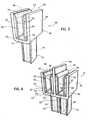
- adapter plug 40has a plug leg 42 at a first end of the adapter plug 40 and that is made from a polymeric or other electrically insulating material.
- the plug leg 42can be inserted, by hand, into the socket receptacle 28 of the electrical connector 27 of the printed circuit board of the drive module 12a-12c.
- a conductive pin 43that extends longitudinally through the plug leg 42 couples to a cooperating conductor (not shown) within the socket receptacle 28. In this way, the adapter plug 40 and the electrical connector 27 are mechanically and electrically connected to each other.
- a plug housing 50 that holds a conductive receptacle 60is connected to an end of the plug leg 42.
- the plug housing 50is made from a polymeric or other electrically insulating material and includes a bottom wall 51 that extends transversely with respect to and outwardly beyond the plug leg 42.
- a pair of side walls 55extends upwardly from outer edges of the bottom wall 51, providing the plug housing 50 with a U-shaped configuration with openings at the top, front, and back.
- the conductive receptacle 60is nested within the adapter plug 40 and is operably connected to the conductive pin 43 so that an electrically conductive path is defined through the conductive receptacle and pin 60, 43.
- the conductive receptacle 60has a pair of opposing leaves 62 that are interconnected through a base strap 66.
- Each of the leaves 62includes an intermediate segment 63 that extends between bent upper and lower ends 64, 65 that extend angularly from the intermediate segment.
- obtuse anglesare defined at points of intersection between the bent upper and lower ends and the intermediate segment. Acute angles are defined at inwardly facing surfaces of the bent lower ends 65 of the leaves 62 and an upwardly facing surface of the base conductive receptacle base strap 66.
- a generally rectangular slot 68is defined between the leaves 62 and base strap 66 and is configured to receive the bus bar module(s) 70 so that it is resiliently held between the leaves 62 of the conductive receptacle 60.
- adapter plug 41 of this embodimentis largely analogous to adapter plug 40 of FIG. 3 , described above, only being configured as a unitized pair of adapter plugs. Accordingly, many of the parts of adapter plug 40 that are also in adapter plug 41 are not described here again with respect to adapter plug 41 because their descriptions above with respect to adapter plug 40 are also applicable here with respect to adapter plug 41.
- adapter plug 41includes a pair of plug legs 42 that extend downwardly from a plug housing 50 that holds a pair of conductive receptacles 60.
- the plug legs 42are spaced from each other by a distance that corresponds to a distance between a pair of receptacles 28 of the electrical connectors 27 of the drive module 12a-12c.
- the electrical connectors 27 of the drive module 12a-12cmay be positive and negative polarity connectors of the DC bus power system for the drive module 12a-12c. This may allow the adapter plug 41 to connect to both positive and negative polarity connectors of the DC bus power system and/or control power to the drive modules 12a-12c in a single installation step.
- the bottom wall 51 of adapter plug 41defines a first segment 52 between one plug leg 42 and conductive receptacle 60 and a second segment 53 between a second plug leg 42 and corresponding conductive receptacle 60.
- An intermediate wall 58extends from a point of intersection of the first and second bottom wall segments 52, 53 of the bottom wall 51.
- the intermediate wall 58extends parallel to and is arranged between the side walls 55 and extends further away from the bottom wall 51 than the side walls 55. In this configuration, the intermediate wall 58 can support a middle portion of a clip 100 from below when the clip 100 is mounted over the plug housing 50, explained in greater detail elsewhere herein.
- the pair of conductive receptacles 60is provided on opposing sides of the intermediate wall 58 so that intermediate wall 58 defines an insulating barrier between the pair of conductive receptacles 60 that receive and resiliently hold the bus bar module 71, similar to how the adapter plug 40 resiliently holds the bus bar module 70, as described in greater detail elsewhere herein.
- bus bar module 70includes a bus bar 72 that is made from an electrically conductive metallic material and a cover 80 that is made from a polymeric or other insulating material.
- a clip 100that is made from a polymeric or other insulating material is provided that engages the bus bar modules 70 and/or adapter plug 40 to selectively cover various surfaces of conductive materials, as described in greater detail elsewhere herein.
- bus bar 72includes blades 73, 74 at opposing ends and a covered segment 75 that extends between and connects the blades 73, 74 to each other.
- the blades 73, 74 and covered segment 75are integral with each other so that a single piece of conductive material defines the bus bar 72.
- the covered segment 75is covered on an upper wall 76 and on most of a pair of side walls 78 of the bus bar 72.
- a lower wall 77 and lower portions of the covered segment 75for example, the lowermost 20 percent of a height of the covered segment 75, is exposed and facing toward the drive modules 12a-12c.
- cover 80includes a lower wall 81 and a pair of side walls 82 that extend downwardly from outer perimeter edges of the lower wall 81.
- the side walls 82include alternating ribs 83 and grooves 84 that define gripping surfaces 85 on the cover 80 that can be grasped by fingers of a user and that may facilitate tool-less insertion and removal of the bus bar module 70 into and from the adapter plug 40.
- a lower wall 87extends between lower edges of the side walls and channel 88 extends upwardly through lower wall 87 toward the upper wall 91.
- the channel 88extends longitudinally through the entire cover 80 and is configured to receive the bus bar 72 so that the cover engages and overlies the covered segment 75 of the bus bar 72.
- cover 80is press or friction fit to the bus bar 72.
- the cover 80is adhered or bonded to the bus bar 72 with suitable adhesive and/or bonding agents, well known to those skilled in the art.
- the cover 80extends around the entire perimeter of the bus bar 72 at the covered segment 75, so that the blades 73, 74 are the only exposed conductive surfaces of the bus bar 72. This can be seen in FIG. 5 as the cover 80 and phantom outline extension that continues around the lower wall 77 of the bus bar 72.
- the cover 80can include upper and lower segments, or other cooperating segments, segments that snap-fit with each other to completely surround the covered segment 75 of the bus bar 72.
- the cover 80 and/or cover componentscan be implemented as a single unitary piece that is applied to the bus bar 72 in an overmolding procedure.
- bus bar module 71 of this embodimentis largely analogous to bus bar module 70 of FIG. 5 , described above, only being configured as including a pair of bus bars 72. Accordingly, many of the parts of bus bar module 70 that are also in bus bar module 71 are not described here again with respect to bus bar module 71 because their descriptions above with respect to bus bar module 70 are also applicable here with respect to adapter plug 71.
- bus bar module 71includes a pair of bus bars 72 and a cover 80.
- Cover 80 of this embodimentincludes first and second segments 90, 92 that hold the pair of bus bars 72.
- the first and second segments 90, 92are defined on opposing sides of a longitudinally extending centerline of the cover 80.
- a pair of intermediate walls 94, 96 that are spaced from each otherextends from the lower wall 81 and are parallel to and are positioned between the side walls 82.
- An opening 89extends through the upper wall 91, between the intermediate walls 94, 96 so that a pair of arms 93 are defined at opposing ends of the upper wall 91 that connect the first and second segments 90, 92 to each other.
- a pair of channels 88is defined between (i) the intermediate wall 94 and an adjacent side wall 82, and (ii) the intermediate wall 96 and the other side wall 82.
- the pair of bus bars 72is mounted in the pair of channels 88 by press or friction fit, adhesion, bonding, or overmolding so that each of the first and second segments 90, 92 extends over a majority or an entirety of the covered segment 75 of the respective bus bar 72.
- a chain(s) of bus bar modules 70, 71 that interconnects the drive modules 12a-12cis defined by multiple bus bar modules 70, 71 that are longitudinally aligned and electrically connected to each other at a splice joint 150.
- the splice joint 150includes the adjacent blades 73, 74 of an aligned pair of adjacent bus bars 72 that are both held between the leaves 62 of the conductive receptacle(s) 60 of the adapter plug 40, 41.
- each of the blades 73, 74extends about halfway along the length of the slot 68. End surface of the covers 80 of the bus bar modules 70, 71 that face each other can abut corresponding end surfaces at opposing sides of the plug housing 50 which may help secure the bus bar modules 70, 71 in a longitudinal direction within the adapter plugs 40, 41.
- clip 100is made from a polymeric or other electrically insulating material and includes an upper wall 102 and a pair of side walls 104 that extends downwardly from opposing side edges of the upper wall 102. As shown in FIGS. 1 and 2 , the clip 100 is long enough so that once the clip 100 is installed over the splice joint 150, it extends entirely over the blades 73, 74 and over parts of the covers 80 of the adjacent bus bar modules 70, 71 that are connected to each other at the splice joint 150. A distance between the clip side walls 104 corresponds to a width of the adapter plug housing 50 and bus bar cover 80.
- Thisprovides the clip 100 with an upside-down U-shape configuration that can fit over the adapter plug 40, 41 and/or bus bar modules 70, 71 for selectively covering the splice joint(s) ( FIGS. 1 and 2 ) by either vertically inserting the clip 100 from above the splice joint 150 or by sliding the clip 100 horizontally across the splice joint 150.
- the plug housing 50 and bus bar covers 80that nest inside and slide within the clip 100 guide the travel of the clip 100 as it travels across the splice joint 150.
- bottom portions of the clip side walls 104include lips or rails (not shown) that extend inwardly toward each other, across the clip 100 and such lips or rails engage the lower walls 87 of the bus bar cover 80 and plug housing bottom wall 51 of the adapter plug 40, 41 while the clip 100 slides thereupon.
- a lock 200includes a lock receptacle 210 that extends into inwardly facing surfaces of the clip side walls 104 and lock projections 220 that extend outwardly from the bus bar cover side walls 82.
- the lock projections 220include ramped surfaces 222 that slant toward the side walls 82 and so that when the clip 100 is slid across to cover the splice joint 150, the clip side walls 104 are deflected outwardly from each other until the lock receptacle 210 overlies the lock projection 220, at which point the clip side walls 104 restore inwardly and the lock projection 220 is held within the lock receptacle 210.
- the lock receptacles 210extend into the bus bar side walls 82 and the lock projections 220 extend into the clip side walls 104.
- one bus bar side wall 82has a lock receptacle 210 and the second bus bar side wall 82 has a lock projection 220, whereas the corresponding clip side walls 104 have the other ones of the lock receptacle and projections 210, 220.
- using the bus bar connector system 30allows a user to electrically interconnect multiple drive modules 12a-12c, without using wires or tools.
- the adapter plugs 40, 41are pressed into the electrical connectors 27 that are attached to the printed circuit boards of the drive modules 12a-12c.
- the bus bar modules 70, 71are then pressed into the adapter plugs 40, 41, so that the blades 73, 74 of the bus bars 72 are squeezed between the leaves 62 of the conductive receptacles 60. This connects the blades 73, 74 that are being held within a common conductive receptacle 60 to each other, at a splice joint 150.
- the splice joint 150is encapsulated between the adapter plug housing 50 and a clip 100 by locking the clip 100 over the splice joint 150. This may be done by, for example, pushing the clip 100 over the adapter plug housing 50, vertically from above. Or the clip 100 may be pushed onto a first cover 80 of a first bus bar module 70, 71. The clip 100 is slid over the splice joint 150 so that the lock receptacles 210 of the clip side walls 104 engage lock projections 220 of bus bar cover side walls 82 of a second cover 80 of a second bus bar module 70, 71 that is being joined to the first bus bar module 70, 71 through the splice joint 150.
- Thisis repeated as many times as necessary to connect the desired number of drive modules 12a-12c or other electronic components to each other. Such procedures may be performed in a reverse order to disconnect the modules 12a-12c or other electronic components from each other in a tool-less manner.
- Thisprovides an easy to assemble and disassemble chain of spliced-together bus bars 72 with substantially no exposed electrically conductive materials or surfaces, for example, more than about 70 percent and preferably more that about 80 percent of the electrically conductive materials of the bus bar connector system 30 being covered by the insulating materials of the covers 80, plug housing 50, and clips 100.
Landscapes
- Connector Housings Or Holding Contact Members (AREA)
- Multi-Conductor Connections (AREA)
- Motor Or Generator Frames (AREA)
Description
- The subject matter disclosed herein relates to electrical conductors that connect electronic components to each other and, more particularly, to wiring systems for connecting servo motor drives to each other within servo motor drive systems.
- Servomotors provide a motor coupled to a sensor, for example, a position sensor such as an encoder, so that feedback control of the motor may be provided, for example, precise positioning control. Typically, a servo motor drive system provides a servo motor, for example, a DC permanent magnet motor and position encoder, which is wired to a servo drive. The servo drive provides a controllable source of DC power as controlled by a feedback signal from the position encoder by, for example, using a PID (proportional-integral-derivative) motor control algorithm.
- The servo drive may be installed in an equipment cabinet to receive the source of DC power. When multiple servo drives are required, this source of DC power is independently wired to each of the servo drives, for example, using terminal blocks and/or standard electrical connectors with pins or blades engaging corresponding sockets. Power has been delivered to printed circuit boards through bus bars that engage connectors that are soldered or screwed to the printed circuit boards.
- German patent
application publication DE 10 2009 003534 A1 describes an electric cross-connector, and, in particular, an end cap therefor, which covers and isolates free ends of a contact strip. The cross-connector has comb-shaped contacts formed at the contact strip and locked in plug-in openings of bus bars of series terminals. - European Patent Application
EP 1 291 977 A2 describes an electrical connection system between modules, which comprises a conductive piece and an insulating piece housing the conductive piece. The conductive piece has free ends not covered by the housing, for being connected with other modules. - Document
FR 2 818 021 A1 - The inventors have recognized that wiring electronic components such as, for example, motor drives to each other can take substantial amounts of time. The inventors have also recognized that different end-use implementations of industrial controls may require highly skilled technicians to assemble motor drives because such end-use implementations tend to differ from each other and may require, for example, using numerous conductors that have to be cut to length to make numerous wire-based "daisy-chain" -type or other sequential connections to interconnect the motor drives. The inventors have further recognized that bus bar based connecting systems typically include bus bar receptacles that have to be soldered or screwed to printed circuit boards, which may take substantial amounts of time to install. The inventors have yet further recognized that the bus bars of such connecting systems present exposed conductive surfaces having relatively large surface areas and that are in locations of motor drive housings that may be subjected to airborne particulate matter which may dirty the electrical contacts and compromise conductivity, and that bus bars of such connecting systems may also be in locations of motor drives housings that may be accessed later by technicians with tools, which may inadvertently produce short circuit conditions by contacting the exposed bus bars. The present invention contemplates a bus bar connector system that addresses various ones of these and other inventor-identified problems and drawbacks of known systems.
This is achieved by the features of claim 1. - In accordance with an aspect of the invention, a bus bar connector system is provided for removably connecting at least two electronic components to each other. The system may include a bus bar module having a bus bar with a first blade having a first exposed conductive surface(s) for connecting to a first electronic component and a second blade having a second exposed conductive surface(s) for connecting to a second electronic component. The bus bar may have a covered segment that extends between the first and second blades. An insulating cover may be connected to the bus bar and extend over the covered segment of the bus bar. A clip may engage the bus bar module and be movable between at least first and second positions. When the clip is in the first position, it may overlie at least one of the first and second blades or exposed conductive surfaces of the bus bar. When the clip is in the second position, it may be spaced from the first and/or second blades or exposed conductive surfaces of the bus bar. This may allow conductors within the bus bar connector system to be covered or non-exposed.
- In accordance with another aspect of the invention, the insulating cover may include a pair of opposing side walls that extend over a pair of opposing side walls of the bus bar module. The clip side walls may slidingly engage the insulating cover side walls so that the clip can move longitudinally with respect to the bus bar module while being transversely guided upon the bus bar module. This may allow conductors within the bus bar connector system to be covered quickly during assembly.
- In accordance with another aspect of the invention, the bus bar connector system includes first and second bus bar modules. The first and second bus bar modules may be connected to each other at a splice joint. The splice joint may include a conductive receptacle that holds respective ends of the first and second bus bar modules, so that their blades or exposed conductive surfaces contact the conductive receptacle so as to electrically connect the first and second bus bar modules to each other. The clip may cover the splice joint so that the covered surfaces of the bus bars of the first and second bus bar modules and the clip define a continuously covered length of the combination of the first and second bus bar modules and splice joint. This may allow bus bars to be quickly coupled to or uncoupled from each other which may facilitate connecting electronic components to each other while providing a connector system that has its conductive surfaces substantially covered with insulating materials.
- In accordance with another aspect of the invention, the conductive receptacle may be provided in a plug housing of an adapter plug. The conductive receptacle may be provided at a first end of the adapter plug and a second end of the adapter plug may be operably coupled to a connector that is fixed to a printed circuit board of an electronic device. This may facilitate quickly connecting electronic devices to each other.
- In accordance with another aspect of the invention, the clip may be slidably mounted to the first bus bar module and may be slidable over the plug housing and upon the second bus bar module, so that the clip covers the entire splice joint and overlaps portions of the first and second bus bar modules. A lock may be provided that prevents sliding movement of the clip with respect to the splice joint. The lock may include a lock projection and a cooperating lock receptacle on the clip and at least one of the adapter plug and first and second bus bar modules, which can engage each other to secure the clip in place when it covers the splice joint. This may allow the clip to remain in a position in which it covers the splice joint that connects bus bars to each other so that conductive materials of the splice joint remain unexposed or substantially covered with insulating materials.
- In accordance with another aspect of the invention, each bus bar module may include a pair of bus bars that are transversely spaced and electrically insulated from each other. Each adapter plug may include a pair of connective receptacles that are transversely spaced from and insulated with respect to each other. This may facilitate simultaneously connecting positive and negative bus bars to electronic components which may simplify connecting such electronic components to each other by allowing multiple connections to be made in a single installation step.
- In accordance with another aspect of the invention, the bus bar connector system may be implemented within an industrial control system and may connect multiple motor drives to each other. First, second, and third adapter plugs may be connected to first, second, and third motor drives of the industrial control system. A pair of bus bar modules may be longitudinally aligned with each other so that outer ends of the bus bar modules are connected to the first and third adapter plugs. Inner or inwardly positioned ends of the bus bar modules may be connected to each other at a spliced joint defined at the second adapter plug and a clip may extend over the splice joint. The bus bar connector system may include the same number of adapter plugs as the number of motor drives that are being connected and may include one fewer bus bar module than the number of motor drives and adapter plugs. This may facilitate connecting multiple motor drives to each other in a tool-less manner.
- To the accomplishment of the foregoing and related ends, certain illustrative aspects of the disclosed innovation are described herein in connection with the following description and annex drawings. These aspects are indicative, however, of but a few of the various ways, in which the principles disclosed herein can be employed, as is intended to include all such aspects and their equivalents. Other advantages and novel features will become apparent from the following detailed description when considered in conjunction with the drawings.
- Various exemplary embodiments of the subject matter disclosed herein are illustrated in the accompanying drawings in which like reference numerals represent like parts throughout, and in which:
FIG. 1 is a simplified perspective view, partially exploded, of a system for connecting motor drives according to an aspect of the present invention;FIG. 2 is a simplified perspective view, partially exploded, of a variant of the system for connecting motor drives ofFIG. 1 ;FIG. 3 is a pictorial view of an adapter plug of the system for connecting motor drives ofFIG. 1 ;FIG. 4 is a pictorial view of an adapter plug of the system for connecting motor drives ofFIG. 2 ;FIG. 5 is a pictorial view of a bus bar module of the system for connecting motor drives ofFIG. 1 ; andFIG. 6 is a pictorial view of a variant of a bus bar module of the system for connecting motor drives ofFIG. 2 .- In describing the various embodiments of the invention which are illustrated in the drawings, specific terminology will be resorted to for the sake of clarity. However, it is not intended that the invention be limited to the specific terms so selected and it is understood that each specific term includes all technical equivalents which operate in a similar manner to accomplish a similar purpose. For example, the word "connected", "attached", or terms similar thereto are often used. They are not limited to direct connection but include connection through other elements where such connection is recognized as being equivalent by those skilled in the art.
- Referring now to
FIGS. 1 and2 , a busbar connector system 30 is a modular system that electronically connects at least two, while allowing for connecting an arbitrary number of, electronic components to each other in a tool-less manner. The busbar connector system 30 is described as being used in a servomotor drive system 10 to simplify its explanation, while noting that the busbar connector system 30 in other embodiments may be implemented to interconnect various other electronic components to each other. - Still referring to
FIGS. 1 and2 , a servomotor drive system 10 may provide formultiple drive modules 12a-12c each having generally rectangular housings 14 that may be mounted in a control cabinet or the like to be in side-by-side adjacent relationship with respect to each other. Rearvertical walls 16 of the housings 14 may include openings through whichconnectors 18 are accessible and to whichpower conductors 20 andsignal conductors 22 may be connected.Power conductors 20 may deliver electrical power to windings of aservomotor 25 for energizing the servomotor.Signal conductors 22 may convey control signals between an encoder of theservomotor 25 and thedrive modules 12a-12c so that thedrive modules 12a-12c may control theservomotor 22 according to methods well known in the art. - Still referring to
FIGS. 1 and2 , horizontal upper walls 26 of the drive modules housings 14 of this embodiment may presentsocket receptacles 28 ofelectrical connectors 27 that are flush mounted with the upper walls 26 of thedrive modules 12a-12c. Theelectrical connectors 27 are operably connected to printed circuit boards of thedrive modules 12a-12c for delivering electrical power to thedrive modules 12a-12c. - Still referring to
FIGS. 1 and2 , a busbar connector system 30 is a modular system that interconnects thedrive modules 12a-12c by wire-free daisy chain connections that can provide main power and/or control power to thedrive modules 12a-12c. In one embodiment, the main power is 100 amp DC bus power and the control power is 16 amp, 24 volt control power, optionally, other values of main and control power, depending on the particular configurations of thedrive modules 12a-12c. The modular configuration of the busbar connector system 30 allows fordrive modules 12a-12c to be added to or removed from the servomotor drive system 10, while making or removing the electrical interconnections between thedrive modules 12a-12c in a tool-less manner. - Still referring to
FIGS. 1 and2 , the busbar connector system 30 includes adapter plugs 40,41 andbus bar modules drive modules 12a-12c. Multiple adapter plugs 40, 41 and multiplebus bar modules bar connector system 30 so that an arbitrary number of parallel electrical conductive paths through chains of thebus bar modules drive modules 12a-12c to be electrically connected to each other. - Referring now to
FIG. 3 ,adapter plug 40 has aplug leg 42 at a first end of theadapter plug 40 and that is made from a polymeric or other electrically insulating material. Theplug leg 42 can be inserted, by hand, into thesocket receptacle 28 of theelectrical connector 27 of the printed circuit board of thedrive module 12a-12c. When theplug leg 42 is inserted into thesocket receptacle 28, aconductive pin 43 that extends longitudinally through theplug leg 42 couples to a cooperating conductor (not shown) within thesocket receptacle 28. In this way, theadapter plug 40 and theelectrical connector 27 are mechanically and electrically connected to each other. - Still referring to
FIG. 3 , at a second end of theadapter plug 40, aplug housing 50 that holds aconductive receptacle 60 is connected to an end of theplug leg 42. Theplug housing 50 is made from a polymeric or other electrically insulating material and includes abottom wall 51 that extends transversely with respect to and outwardly beyond theplug leg 42. A pair ofside walls 55 extends upwardly from outer edges of thebottom wall 51, providing theplug housing 50 with a U-shaped configuration with openings at the top, front, and back. Theconductive receptacle 60 is nested within theadapter plug 40 and is operably connected to theconductive pin 43 so that an electrically conductive path is defined through the conductive receptacle andpin conductive receptacle 60 has a pair of opposingleaves 62 that are interconnected through abase strap 66. Each of theleaves 62 includes anintermediate segment 63 that extends between bent upper and lower ends 64, 65 that extend angularly from the intermediate segment. - Still referring to
FIG. 3 , at surfaces of theleaves 62 that face outwardly or toward the plughousing side walls 55, obtuse angles are defined at points of intersection between the bent upper and lower ends and the intermediate segment. Acute angles are defined at inwardly facing surfaces of the bent lower ends 65 of theleaves 62 and an upwardly facing surface of the base conductivereceptacle base strap 66. A generallyrectangular slot 68 is defined between theleaves 62 andbase strap 66 and is configured to receive the bus bar module(s) 70 so that it is resiliently held between theleaves 62 of theconductive receptacle 60. - Referring now to
FIG. 4 , adapter plug 41 of this embodiment is largely analogous to adapter plug 40 ofFIG. 3 , described above, only being configured as a unitized pair of adapter plugs. Accordingly, many of the parts ofadapter plug 40 that are also inadapter plug 41 are not described here again with respect to adapter plug 41 because their descriptions above with respect to adapter plug 40 are also applicable here with respect toadapter plug 41. - Still referring to
FIG. 4 ,adapter plug 41 includes a pair ofplug legs 42 that extend downwardly from aplug housing 50 that holds a pair ofconductive receptacles 60. Theplug legs 42 are spaced from each other by a distance that corresponds to a distance between a pair ofreceptacles 28 of theelectrical connectors 27 of thedrive module 12a-12c. Theelectrical connectors 27 of thedrive module 12a-12c may be positive and negative polarity connectors of the DC bus power system for thedrive module 12a-12c. This may allow theadapter plug 41 to connect to both positive and negative polarity connectors of the DC bus power system and/or control power to thedrive modules 12a-12c in a single installation step. - Still referring to
FIG. 4 , in this embodiment, thebottom wall 51 ofadapter plug 41 defines afirst segment 52 between oneplug leg 42 andconductive receptacle 60 and asecond segment 53 between asecond plug leg 42 and correspondingconductive receptacle 60. Anintermediate wall 58 extends from a point of intersection of the first and secondbottom wall segments bottom wall 51. Theintermediate wall 58 extends parallel to and is arranged between theside walls 55 and extends further away from thebottom wall 51 than theside walls 55. In this configuration, theintermediate wall 58 can support a middle portion of aclip 100 from below when theclip 100 is mounted over theplug housing 50, explained in greater detail elsewhere herein. The pair ofconductive receptacles 60 is provided on opposing sides of theintermediate wall 58 so thatintermediate wall 58 defines an insulating barrier between the pair ofconductive receptacles 60 that receive and resiliently hold thebus bar module 71, similar to how theadapter plug 40 resiliently holds thebus bar module 70, as described in greater detail elsewhere herein. - Referring now to
FIGS. 1 and5 ,bus bar module 70 includes abus bar 72 that is made from an electrically conductive metallic material and acover 80 that is made from a polymeric or other insulating material. Aclip 100 that is made from a polymeric or other insulating material is provided that engages thebus bar modules 70 and/oradapter plug 40 to selectively cover various surfaces of conductive materials, as described in greater detail elsewhere herein. - Still referring to
FIGS. 1 and5 ,bus bar 72 includesblades segment 75 that extends between and connects theblades blades segment 75 are integral with each other so that a single piece of conductive material defines thebus bar 72. As shown inFIG. 1 , in this embodiment, the coveredsegment 75 is covered on anupper wall 76 and on most of a pair ofside walls 78 of thebus bar 72. Alower wall 77 and lower portions of the coveredsegment 75, for example, the lowermost 20 percent of a height of the coveredsegment 75, is exposed and facing toward thedrive modules 12a-12c. - Referring now to
FIG. 5 , cover 80 includes alower wall 81 and a pair ofside walls 82 that extend downwardly from outer perimeter edges of thelower wall 81. In this embodiment, theside walls 82 include alternatingribs 83 andgrooves 84 that define grippingsurfaces 85 on thecover 80 that can be grasped by fingers of a user and that may facilitate tool-less insertion and removal of thebus bar module 70 into and from theadapter plug 40. A lower wall 87 extends between lower edges of the side walls andchannel 88 extends upwardly through lower wall 87 toward theupper wall 91. - The
channel 88 extends longitudinally through theentire cover 80 and is configured to receive thebus bar 72 so that the cover engages and overlies the coveredsegment 75 of thebus bar 72. In one embodiment, cover 80 is press or friction fit to thebus bar 72. In one embodiment, thecover 80 is adhered or bonded to thebus bar 72 with suitable adhesive and/or bonding agents, well known to those skilled in the art. In another embodiment, thecover 80 extends around the entire perimeter of thebus bar 72 at the coveredsegment 75, so that theblades bus bar 72. This can be seen inFIG. 5 as thecover 80 and phantom outline extension that continues around thelower wall 77 of thebus bar 72. In such embodiment, thecover 80 can include upper and lower segments, or other cooperating segments, segments that snap-fit with each other to completely surround the coveredsegment 75 of thebus bar 72. Or, thecover 80 and/or cover components can be implemented as a single unitary piece that is applied to thebus bar 72 in an overmolding procedure. - Referring now to
FIG.6 ,bus bar module 71 of this embodiment is largely analogous tobus bar module 70 ofFIG. 5 , described above, only being configured as including a pair of bus bars 72. Accordingly, many of the parts ofbus bar module 70 that are also inbus bar module 71 are not described here again with respect tobus bar module 71 because their descriptions above with respect tobus bar module 70 are also applicable here with respect toadapter plug 71. - Still referring to
FIG. 6 ,bus bar module 71 includes a pair ofbus bars 72 and acover 80.Cover 80 of this embodiment includes first andsecond segments second segments cover 80. A pair ofintermediate walls lower wall 81 and are parallel to and are positioned between theside walls 82. Anopening 89 extends through theupper wall 91, between theintermediate walls arms 93 are defined at opposing ends of theupper wall 91 that connect the first andsecond segments - Still referring to
FIG. 6 , a pair ofchannels 88 is defined between (i) theintermediate wall 94 and anadjacent side wall 82, and (ii) theintermediate wall 96 and theother side wall 82. The pair of bus bars 72 is mounted in the pair ofchannels 88 by press or friction fit, adhesion, bonding, or overmolding so that each of the first andsecond segments segment 75 of therespective bus bar 72. - Referring again to
FIGS. 1 and2 , a chain(s) ofbus bar modules drive modules 12a-12c is defined by multiplebus bar modules adjacent blades leaves 62 of the conductive receptacle(s) 60 of theadapter plug blades slot 68. End surface of thecovers 80 of thebus bar modules plug housing 50 which may help secure thebus bar modules - Referring now to
FIGS. 5 and6 ,clip 100 is made from a polymeric or other electrically insulating material and includes anupper wall 102 and a pair ofside walls 104 that extends downwardly from opposing side edges of theupper wall 102. As shown inFIGS. 1 and2 , theclip 100 is long enough so that once theclip 100 is installed over the splice joint 150, it extends entirely over theblades covers 80 of the adjacentbus bar modules clip side walls 104 corresponds to a width of the adapter plughousing 50 andbus bar cover 80. This provides theclip 100 with an upside-down U-shape configuration that can fit over theadapter plug bus bar modules FIGS. 1 and2 ) by either vertically inserting theclip 100 from above the splice joint 150 or by sliding theclip 100 horizontally across the splice joint 150. When theclip 100 is slid over across the splice joint 150, theplug housing 50 and bus bar covers 80 that nest inside and slide within theclip 100 guide the travel of theclip 100 as it travels across the splice joint 150. In one embodiment, bottom portions of theclip side walls 104 include lips or rails (not shown) that extend inwardly toward each other, across theclip 100 and such lips or rails engage the lower walls 87 of thebus bar cover 80 and plughousing bottom wall 51 of theadapter plug clip 100 slides thereupon. - Referring again to
FIGS 1 and2 , alock 200 includes alock receptacle 210 that extends into inwardly facing surfaces of theclip side walls 104 and lockprojections 220 that extend outwardly from the bus barcover side walls 82. Thelock projections 220 include rampedsurfaces 222 that slant toward theside walls 82 and so that when theclip 100 is slid across to cover the splice joint 150, theclip side walls 104 are deflected outwardly from each other until thelock receptacle 210 overlies thelock projection 220, at which point theclip side walls 104 restore inwardly and thelock projection 220 is held within thelock receptacle 210. In one embodiment, thelock receptacles 210 extend into the busbar side walls 82 and thelock projections 220 extend into theclip side walls 104. In another embodiment, one busbar side wall 82 has alock receptacle 210 and the second busbar side wall 82 has alock projection 220, whereas the correspondingclip side walls 104 have the other ones of the lock receptacle andprojections - In light of the above, using the bus
bar connector system 30 allows a user to electrically interconnectmultiple drive modules 12a-12c, without using wires or tools. The adapter plugs 40, 41 are pressed into theelectrical connectors 27 that are attached to the printed circuit boards of thedrive modules 12a-12c. Thebus bar modules blades leaves 62 of theconductive receptacles 60. This connects theblades conductive receptacle 60 to each other, at a splice joint 150. The splice joint 150 is encapsulated between the adapter plughousing 50 and aclip 100 by locking theclip 100 over the splice joint 150. This may be done by, for example, pushing theclip 100 over the adapter plughousing 50, vertically from above. Or theclip 100 may be pushed onto afirst cover 80 of a firstbus bar module clip 100 is slid over the splice joint 150 so that thelock receptacles 210 of theclip side walls 104 engagelock projections 220 of bus barcover side walls 82 of asecond cover 80 of a secondbus bar module bus bar module drive modules 12a-12c or other electronic components to each other. Such procedures may be performed in a reverse order to disconnect themodules 12a-12c or other electronic components from each other in a tool-less manner. This provides an easy to assemble and disassemble chain of spliced-together bus bars 72 with substantially no exposed electrically conductive materials or surfaces, for example, more than about 70 percent and preferably more that about 80 percent of the electrically conductive materials of the busbar connector system 30 being covered by the insulating materials of thecovers 80, plughousing 50, and clips 100. - It should be understood that the invention is not limited in its application to the details of construction and arrangements of the components set forth herein. The invention is capable of other embodiments and of being practiced or carried out in various ways. Variations and modifications of the foregoing are within the scope of the present invention. It also being understood that the invention disclosed and defined herein extends to all alternative combinations of two or more of the individual features mentioned or evident from the text and/or drawings. All of these different combinations constitute various alternative aspects of the present invention. The embodiments described herein explain the best modes known for practicing the invention and will enable others skilled in the art to utilize the invention.
Claims (14)
- A bus bar connector system (30) for removably connecting at least two electronic components (12) to each other, comprising,
a bus bar module (70; 71) that includes
a bus bar (72) with a first blade (73) for connecting to a first electronic component (12a), a second blade (74) for connecting to a second electronic component (12b), and a covered segment (75) extending between and connecting the first and second blades (73, 74); and
a cover (80) that is made from an insulating material and that is connected to the bus bar (72) and extends over the covered segment (75) of the bus bar (72);
characterized by
a first electrical connector (27) operably connected to a printed circuit board in the first electronic component (12a), wherein the first electrical connector (27) includes a first mating portion (28); and
a first adapter plug (40; 41) including
a second mating portion (42), wherein the second mating portion engages the first mating portion to establish an electrical connection between the first electrical connector (27) and the first adapter plug (40), and
a conductive receptacle (60) configured to receive the first blade (73) of the bus bar (72), wherein the conductive receptacle (60) is electrically connected to the second mating portion (42) such that the first adapter plug (40) establishes an electrical connection between the bus bar (72) and the first electrical connector (27). - The bus bar connector system (30) of claim 1 further comprising a clip (100) that engages the bus bar module (70; 71) and is movable between at least first and second positions, such that the clip (100) in the first position overlies at least one of the first and second blades (73, 74) of the bus bar (72), and the clip (100) in the second position is spaced from the at least one of the first and second blades (73, 74) of the bus bar (72).
- The bus bar connector system (30) of claim 2, the cover (80) further comprising a pair of opposing side walls (82) that extends over a pair of opposing side walls (78) of the bus bar (72) and the clip (100) engages and is longitudinally movable with respect to the opposing side walls (82) of the cover (80).
- The bus bar connector system (30) according to any of claims 1 to 3, wherein the bus bar module (70; 71) includes first and second bus bars (72) that are transversely spaced from each other, the cover (80) extending between and connecting the first and second bus bars (72) to each other while electrically insulating the first and second bus bars (72) from each other.
- The bus bar connector system (30) of claim 4, wherein the cover includes a first segment (90) that extends over the covered surface (75) of the first bus bar (72), a second segment (92) that is transversely spaced from the first segment (90) and extends over a covered surface (75) of the second bus bar (72), and at least one arm (93) that extends between and connects the first and second segments (90, 92) of the cover to each other.
- The bus bar connector system (30) of claim 4 or 5, wherein the adapter plug (40, 41) includes a plug housing and a second conductive receptacle (60), defining, along with the conductive receptacle (60), a pair of conductive receptacles that are provided in the housing (50), wherein the pair of conductive receptacles are insulated from each other, the first and second bus bars (72) of the bus bar module (70, 71) being removably connected to the pair of conductive receptacles (60) of the adapter plug (40, 41) such that the pair of conductive receptacles (60) and first and second bus bars (72) of the bus bar module (70, 71) define two separate paths of electrical conductivity therethrough.
- The bus bar connector system according to any of claims 1 to 6, wherein the conductive receptacle (60) includes:a first leaf (62) having an upper end (64) and a lower end (65) and defining a first side of the conductive receptacle (60),a second leaf (62) having an upper end (64) and a lower end (65) and defining a second side of the conductive receptacle (60), anda base strap (66) connecting the lower end (65) of the first leaf (62) to the lower end (65) of the second leaf (62).
- The bus bar connector system of claim 2, wherein the bus bar module is a first bus bar module, the bus bar is a first bus bar and the cover is a first cover, the bus bar connector system further comprising:a second bus bar module (70; 71) that includes a second bus bar with a blade (43); anda second cover (80) that is made from an insulating material and that extends over at least a portion of the second bus bar (72).
- The bus bar connector system of claim 8, wherein the clip (100) is made from an insulating material and first and second covers (80) of the first and second bus bar modules (70; 71) extend at least partially under the clip (100) so that the blades (73, 74) of the first and second bus bar modules (70; 71) are enclosed between the clip (100) and the adapter plug (40; 41).
- The bus bar connector system of claim 1, wherein the bus bar module is a first bus bar module, the bus bar is first bus bar, and the cover is a first cover, and the system includes:a second bus bar module (70; 71) having a second bus bar (72) with a blade (43) and a covered segment (75) that extends from the blade (43),a second cover (80) that is made from an insulating material and that is connected to the second bus bar (72) and extends over the covered segment (75) of the second bus bar (72), anda splice joint (150) defined by the conductive receptacle, wherein the conductive receptacle is configured to receive the blade (73) from each of the first and second bus bars (72) adjacent to each other.
- The bus bar connector system of claim 10 further comprising a clip (100) that engages the first and second bus bar modules (70; 71) and wherein the clip (100) is made from an insulating material and covers the splice joint (150) so that the covers of the first and second bus bar modules (70; 71) and the clip (100) define a continuously insulated covered length of the combination of the first and second bus bar modules (70; 71) and the splice joint (150).
- The bus bar connector system of claim 11, wherein the first and second covers (80) and the plug housing have corresponding widths so that the clip (100) can engage and slide between the first and second bus bar modules and the adapter plug.
- The bus bar connector system of claim 11 or 12, further comprising a lock securing the clip (100) over the splice joint (150), the lock including one of a lock projection (220) and a lock receptacle (210) provided on the clip (100) and the other one of a lock projection (220) and a lock receptacle (210) on one of the adapter plug (40; 41), the first bus bar module (70; 71), and the second bus bar module (70; 71).
- The bus bar connector system of any one of claims 10 to 13, wherein each of the first and second bus bar modules (70; 71) includes a pair of bus bars (72) that are transversely spaced and electrically insulated from each other.
Applications Claiming Priority (2)
| Application Number | Priority Date | Filing Date | Title |
|---|---|---|---|
| US201161476076P | 2011-04-15 | 2011-04-15 | |
| US13/267,477US8585422B2 (en) | 2011-04-15 | 2011-10-06 | System for connecting motor drives |
Publications (3)
| Publication Number | Publication Date |
|---|---|
| EP2511993A2 EP2511993A2 (en) | 2012-10-17 |
| EP2511993A3 EP2511993A3 (en) | 2014-11-26 |
| EP2511993B1true EP2511993B1 (en) | 2016-06-29 |
Family
ID=46044392
Family Applications (1)
| Application Number | Title | Priority Date | Filing Date |
|---|---|---|---|
| EP12164208.6AActiveEP2511993B1 (en) | 2011-04-15 | 2012-04-16 | System for connecting motor drives |
Country Status (3)
| Country | Link |
|---|---|
| US (2) | US8585422B2 (en) |
| EP (1) | EP2511993B1 (en) |
| CN (2) | CN103151661B (en) |
Cited By (1)
| Publication number | Priority date | Publication date | Assignee | Title |
|---|---|---|---|---|
| EP4080686A1 (en)* | 2021-04-21 | 2022-10-26 | Rosenberger Hochfrequenztechnik GmbH & Co. KG | Electrical connector, electrical connection element and electrical connection |
Families Citing this family (36)
| Publication number | Priority date | Publication date | Assignee | Title |
|---|---|---|---|---|
| US8585422B2 (en) | 2011-04-15 | 2013-11-19 | Rockwell Automation Technologies, Inc. | System for connecting motor drives |
| US8986030B2 (en) | 2012-12-06 | 2015-03-24 | Phoenix Contact Development and Manufacturing, Inc. | Modular electric power distribution system |
| US9093804B2 (en)* | 2013-10-04 | 2015-07-28 | Rockwell Automation Technologies, Inc. | Apparatus for connecting a shared DC bus link |
| EP3097612B1 (en) | 2014-01-20 | 2018-08-22 | Schneider Electric IT Corporation | Busbar connector assembly and securing method thereof |
| US9520703B2 (en)* | 2014-07-31 | 2016-12-13 | Power Distribution, Inc. | Electrical busway splice connector |
| US9190791B1 (en) | 2014-07-31 | 2015-11-17 | Power Distribution, Inc. | Electrical busway splice connector |
| US9450359B2 (en)* | 2014-12-18 | 2016-09-20 | Schneider Electric It Corporation | Interface apparatus and method for connecting plug-in units to a busway |
| US10499514B2 (en)* | 2015-05-12 | 2019-12-03 | Mitsubishi Electric Corporation | Vehicular control device |
| US9882421B2 (en) | 2015-05-14 | 2018-01-30 | Rockwell Automation Technologies, Inc. | Method and apparatus for increasing current capacity of a distributed drive system |
| DE102016216933A1 (en)* | 2015-09-16 | 2017-03-16 | Schaeffler Technologies AG & Co. KG | E-machine and hybrid module with electric machine |
| US9979109B2 (en)* | 2015-11-10 | 2018-05-22 | Lenovo Enterprise Solutions (Singapore) Pte. Ltd. | Card stabilizer bracket |
| KR102579568B1 (en)* | 2015-11-12 | 2023-09-18 | 엘지이노텍 주식회사 | Busbar and Motor having the same |
| DE202016100307U1 (en)* | 2016-01-22 | 2017-04-26 | Weidmüller Interface GmbH & Co. KG | Series device arrangement with a power bus system |
| CN105846192A (en)* | 2016-03-23 | 2016-08-10 | 吴传涛 | Small gear speed regulating motor power supply cable connector |
| CN107425313A (en)* | 2016-04-21 | 2017-12-01 | 理想工业公司 | The electric connector with printed circuit board (PCB) for active power network bus-bar system |
| CN107364456B (en)* | 2016-05-12 | 2020-10-27 | 通用电气全球采购有限责任公司 | Inverter driving assembly and bus bar for inverter driving assembly of vehicle |
| JP6840542B2 (en)* | 2017-01-04 | 2021-03-10 | 日本航空電子工業株式会社 | connector |
| CN108306233B (en)* | 2017-04-10 | 2020-01-03 | 泉州睿郎机电技术有限公司 | Hydraulic motor type electric bus bar connecting tool |
| CN107732548B (en)* | 2017-04-10 | 2019-05-03 | 龚柱 | Pneumatic power bus connection tool |
| GB2566449A (en)* | 2017-09-07 | 2019-03-20 | Nidec Control Techniques Ltd | Power connector systems |
| JP7004197B2 (en)* | 2017-09-22 | 2022-01-21 | 株式会社オートネットワーク技術研究所 | Electrical connection member |
| US10283895B1 (en) | 2017-12-20 | 2019-05-07 | Lear Corporation | Electrical terminal assembly with split shroud |
| US10396482B2 (en) | 2017-12-20 | 2019-08-27 | Lear Corporation | Electrical terminal assembly with locked spring member |
| US10177513B1 (en)* | 2017-12-28 | 2019-01-08 | Lear Corporation | Bus bar assembly with a system to form and secure connections to the terminals on a bus bar |
| DE202018100964U1 (en) | 2018-02-21 | 2019-05-23 | Weidmüller Interface GmbH & Co. KG | Contact and busbar arrangement |
| DE102019102011A1 (en)* | 2018-02-21 | 2019-08-22 | Weidmüller Interface GmbH & Co. KG | Contact and busbar arrangement |
| DE202018100959U1 (en)* | 2018-02-21 | 2019-05-23 | Weidmüller Interface GmbH & Co. KG | Contact and busbar arrangement |
| EP3540872A1 (en)* | 2018-03-15 | 2019-09-18 | Wöhner Besitz GmbH | A hybrid busbar for a busbar system |
| CN113508498B (en)* | 2019-01-21 | 2025-03-18 | 皇家精密制品有限责任公司 | Bus system |
| EP4050744A1 (en) | 2021-02-24 | 2022-08-31 | Erico International Corporation | Support assembly for power conductors |
| WO2022210423A1 (en)* | 2021-03-30 | 2022-10-06 | 株式会社オートネットワーク技術研究所 | Terminal module |
| CN115207731A (en)* | 2021-04-13 | 2022-10-18 | 泰科电子(上海)有限公司 | Bus Bar Subassemblies and Electrical Assemblies |
| CN113437570B (en)* | 2021-07-08 | 2022-12-23 | 吉林工程技术师范学院 | A splicing track connection mechanism for rail transit |
| CN116937081A (en)* | 2022-03-31 | 2023-10-24 | 宁德时代新能源科技股份有限公司 | Electrode terminals, pole assemblies, batteries and electrical equipment |
| US20240305052A1 (en)* | 2023-03-06 | 2024-09-12 | Juniper Design Group Inc. | Low-profile track system |
| CN118659159B (en)* | 2024-06-13 | 2024-12-06 | 湖北兴和电力新材料股份有限公司 | Protective bus connecting device |
Family Cites Families (34)
| Publication number | Priority date | Publication date | Assignee | Title |
|---|---|---|---|---|
| DE7223465U (en)* | 1972-06-23 | 1972-09-14 | Bbc Ag | |
| US4195194A (en)* | 1978-05-22 | 1980-03-25 | Amp Incorporated | Junction box |
| US4423917A (en)* | 1981-11-19 | 1984-01-03 | Amp Incorporated | Electrical connector having movable contact units |
| US4475781A (en) | 1982-12-08 | 1984-10-09 | Amp Incorporated | Bussing system for stacked array of panel boards |
| US4616893A (en)* | 1984-04-25 | 1986-10-14 | Amp Incorporated | Surface mount, miniature, bussing connector |
| US4721471A (en)* | 1986-07-31 | 1988-01-26 | Amp Incorporated | Power bus system for printed circuit boards |
| US4845592A (en)* | 1987-08-31 | 1989-07-04 | Amp Incorporated | Flexible bussing system for distributing power to printed circuit boards, backplanes or the like |
| US5024627A (en)* | 1990-06-29 | 1991-06-18 | Amp Incorporated | Float mounted receptacle contact assembly for card cage |
| US5073120A (en)* | 1991-01-25 | 1991-12-17 | Amp Incorporated | Power distribution unit |
| US5203724A (en)* | 1991-11-05 | 1993-04-20 | Amp Incorporated | Firewall terminal block |
| US5139426A (en)* | 1991-12-11 | 1992-08-18 | Amp Incorporated | Adjunct power connector |
| US5252086A (en)* | 1992-05-28 | 1993-10-12 | Steelcase Inc. | Modular powerway with selectable receptacle |
| US5396027A (en)* | 1992-11-12 | 1995-03-07 | Dekko Engineering, Inc. | Strip electrical system |
| US5383799A (en)* | 1993-03-26 | 1995-01-24 | Fladung; Philip E. | Multi-purpose plug-in electrical outlet adaptor |
| CN1055603C (en) | 1995-02-28 | 2000-08-16 | 松下电工株式会社 | Discharge lamp operating device |
| US6086388A (en)* | 1998-05-05 | 2000-07-11 | Tvm Group, Inc. | Auxiliary switch system for use with removable circuit breaker |
| US6201350B1 (en) | 1998-11-20 | 2001-03-13 | Denso Corporation | Discharge lamp lightning apparatus and manufacturing method therefor |
| FR2818021B1 (en)* | 2000-12-08 | 2005-01-28 | Seifel Sa | DEVICE FOR ELECTRICALLY COUPLABLE CONNECTION OF AN ELECTRIC CABLES SET TO A PLATINUM WITH A CONDUCTIVE BAR ASSEMBLY |
| SE520722C2 (en) | 2001-03-30 | 2003-08-19 | Abb Ab | Insulated power supply unit and rectifier with such unit |
| ES2199030B1 (en)* | 2001-09-07 | 2005-05-01 | Ge Power Controls Iberica, S.L. | ELECTRICAL CONNECTION SYSTEM BETWEEN MODULES FOR THE PROTECTION OF ELECTRICAL DISTRIBUTION CIRCUITS. |
| WO2007081378A1 (en)* | 2005-04-29 | 2007-07-19 | Byrne Norman R | Center connect single-sided junction block |
| US7717747B2 (en) | 2006-11-06 | 2010-05-18 | Gm Global Technology Operations, Inc. | Power inverter connector having integrated current sensors |
| JP4833826B2 (en)* | 2006-12-28 | 2011-12-07 | 三菱電線工業株式会社 | Connection member and harness connection body using the member |
| WO2008081620A1 (en)* | 2006-12-28 | 2008-07-10 | Mitsubishi Cable Industries, Ltd. | Connection member and harness connector |
| US7527523B2 (en)* | 2007-05-02 | 2009-05-05 | Tyco Electronics Corporation | High power terminal block assembly |
| US20080299838A1 (en) | 2007-05-31 | 2008-12-04 | Christoph Kopp | Power connectors for mating with bus bars |
| EP2048746B1 (en) | 2007-08-13 | 2016-10-05 | Tyco Electronics Nederland B.V. | Busbar connection system |
| JP5179855B2 (en)* | 2007-12-21 | 2013-04-10 | 矢崎総業株式会社 | Assembly structure of bus bar block |
| DE102009003534B4 (en)* | 2009-02-24 | 2011-06-16 | Conrad Stanztechnik Gmbh | Cross connector for terminal blocks |
| JP4708487B2 (en) | 2009-07-06 | 2011-06-22 | トヨタ自動車株式会社 | Inverter relay connection member |
| SG10201501207PA (en) | 2010-04-22 | 2015-04-29 | Universal Electric Corp | Improved press-fit busbar and busway employing same |
| US8585422B2 (en) | 2011-04-15 | 2013-11-19 | Rockwell Automation Technologies, Inc. | System for connecting motor drives |
| US8686288B2 (en) | 2011-05-31 | 2014-04-01 | Tesla Motors, Inc. | Power electronics interconnection for electric motor drives |
| US8388389B2 (en) | 2011-07-07 | 2013-03-05 | Tyco Electronics Corporation | Electrical connectors having opposing electrical contacts |
- 2011
- 2011-10-06USUS13/267,477patent/US8585422B2/enactiveActive
- 2012
- 2012-04-16EPEP12164208.6Apatent/EP2511993B1/enactiveActive
- 2012-04-16CNCN201210112410.6Apatent/CN103151661B/enactiveActive
- 2012-04-16CNCN201510388398.5Apatent/CN105006717B/enactiveActive
- 2013
- 2013-10-17USUS14/056,523patent/US9190759B2/enactiveActive
Cited By (1)
| Publication number | Priority date | Publication date | Assignee | Title |
|---|---|---|---|---|
| EP4080686A1 (en)* | 2021-04-21 | 2022-10-26 | Rosenberger Hochfrequenztechnik GmbH & Co. KG | Electrical connector, electrical connection element and electrical connection |
Also Published As
| Publication number | Publication date |
|---|---|
| CN103151661B (en) | 2015-08-05 |
| US8585422B2 (en) | 2013-11-19 |
| EP2511993A3 (en) | 2014-11-26 |
| CN103151661A (en) | 2013-06-12 |
| EP2511993A2 (en) | 2012-10-17 |
| US20120264317A1 (en) | 2012-10-18 |
| US9190759B2 (en) | 2015-11-17 |
| CN105006717B (en) | 2017-11-21 |
| CN105006717A (en) | 2015-10-28 |
| US20140045353A1 (en) | 2014-02-13 |
Similar Documents
| Publication | Publication Date | Title |
|---|---|---|
| EP2511993B1 (en) | System for connecting motor drives | |
| US7537496B2 (en) | Electrical terminal block | |
| CN102668260B (en) | System plug connector | |
| US7601013B2 (en) | Connection or device adapter | |
| EP3149809B1 (en) | Electrical connector for use with printed circuit boards | |
| US9755384B2 (en) | Bridging module having a housing with a latching device for latching to a mounting rail | |
| CN106068582A (en) | Terminal Blocks and Terminal Blocks | |
| EP2858229B1 (en) | Apparatus for Connecting a Shared DC Bus Link | |
| JP5354573B2 (en) | Electrical cross connector | |
| CN102844939A (en) | Connection apparatus with variable electrical connection between conductor terminals | |
| EP2678903B1 (en) | A modular electrical connection unit | |
| US7446635B2 (en) | Combination of two electromagnetic switching devices | |
| CN111434196B (en) | Building-block system for making electronic devices | |
| US7092244B2 (en) | Connection or distributing device for electrical installation equipment | |
| US11196193B2 (en) | Conductor terminal, assortment of at least one base module and differently designed conductor connecting modules of a conductor terminal, and conductor terminal block | |
| EP0798835A1 (en) | Board and interconnection device for electrical installations with modular devices | |
| JP4364071B2 (en) | Unit cable for indoor wiring | |
| CN106159479B (en) | Wiring board | |
| WO2008045924A1 (en) | Intermediate connection device and electrical socket with same | |
| EP0526256B1 (en) | Connectors | |
| KR20110006992U (en) | Kit for wiring | |
| HK1105049A1 (en) | Power feeding module | |
| HK1105049B (en) | Power feeding module |
Legal Events
| Date | Code | Title | Description |
|---|---|---|---|
| PUAI | Public reference made under article 153(3) epc to a published international application that has entered the european phase | Free format text:ORIGINAL CODE: 0009012 | |
| AK | Designated contracting states | Kind code of ref document:A2 Designated state(s):AL AT BE BG CH CY CZ DE DK EE ES FI FR GB GR HR HU IE IS IT LI LT LU LV MC MK MT NL NO PL PT RO RS SE SI SK SM TR | |
| AX | Request for extension of the european patent | Extension state:BA ME | |
| PUAL | Search report despatched | Free format text:ORIGINAL CODE: 0009013 | |
| AK | Designated contracting states | Kind code of ref document:A3 Designated state(s):AL AT BE BG CH CY CZ DE DK EE ES FI FR GB GR HR HU IE IS IT LI LT LU LV MC MK MT NL NO PL PT RO RS SE SI SK SM TR | |
| AX | Request for extension of the european patent | Extension state:BA ME | |
| RIC1 | Information provided on ipc code assigned before grant | Ipc:H01R 13/514 20060101ALI20141017BHEP Ipc:H01R 9/26 20060101ALI20141017BHEP Ipc:H01R 31/08 20060101AFI20141017BHEP | |
| 17P | Request for examination filed | Effective date:20150521 | |
| RBV | Designated contracting states (corrected) | Designated state(s):AL AT BE BG CH CY CZ DE DK EE ES FI FR GB GR HR HU IE IS IT LI LT LU LV MC MK MT NL NO PL PT RO RS SE SI SK SM TR | |
| GRAP | Despatch of communication of intention to grant a patent | Free format text:ORIGINAL CODE: EPIDOSNIGR1 | |
| INTG | Intention to grant announced | Effective date:20160223 | |
| GRAS | Grant fee paid | Free format text:ORIGINAL CODE: EPIDOSNIGR3 | |
| GRAA | (expected) grant | Free format text:ORIGINAL CODE: 0009210 | |
| AK | Designated contracting states | Kind code of ref document:B1 Designated state(s):AL AT BE BG CH CY CZ DE DK EE ES FI FR GB GR HR HU IE IS IT LI LT LU LV MC MK MT NL NO PL PT RO RS SE SI SK SM TR | |
| REG | Reference to a national code | Ref country code:GB Ref legal event code:FG4D | |
| REG | Reference to a national code | Ref country code:CH Ref legal event code:EP | |
| REG | Reference to a national code | Ref country code:AT Ref legal event code:REF Ref document number:809764 Country of ref document:AT Kind code of ref document:T Effective date:20160715 | |
| REG | Reference to a national code | Ref country code:IE Ref legal event code:FG4D | |
| REG | Reference to a national code | Ref country code:DE Ref legal event code:R096 Ref document number:602012019889 Country of ref document:DE | |
| REG | Reference to a national code | Ref country code:LT Ref legal event code:MG4D | |
| PG25 | Lapsed in a contracting state [announced via postgrant information from national office to epo] | Ref country code:LT Free format text:LAPSE BECAUSE OF FAILURE TO SUBMIT A TRANSLATION OF THE DESCRIPTION OR TO PAY THE FEE WITHIN THE PRESCRIBED TIME-LIMIT Effective date:20160629 Ref country code:NO Free format text:LAPSE BECAUSE OF FAILURE TO SUBMIT A TRANSLATION OF THE DESCRIPTION OR TO PAY THE FEE WITHIN THE PRESCRIBED TIME-LIMIT Effective date:20160929 Ref country code:FI Free format text:LAPSE BECAUSE OF FAILURE TO SUBMIT A TRANSLATION OF THE DESCRIPTION OR TO PAY THE FEE WITHIN THE PRESCRIBED TIME-LIMIT Effective date:20160629 | |
| REG | Reference to a national code | Ref country code:NL Ref legal event code:MP Effective date:20160629 | |
| PG25 | Lapsed in a contracting state [announced via postgrant information from national office to epo] | Ref country code:HR Free format text:LAPSE BECAUSE OF FAILURE TO SUBMIT A TRANSLATION OF THE DESCRIPTION OR TO PAY THE FEE WITHIN THE PRESCRIBED TIME-LIMIT Effective date:20160629 Ref country code:NL Free format text:LAPSE BECAUSE OF FAILURE TO SUBMIT A TRANSLATION OF THE DESCRIPTION OR TO PAY THE FEE WITHIN THE PRESCRIBED TIME-LIMIT Effective date:20160629 Ref country code:RS Free format text:LAPSE BECAUSE OF FAILURE TO SUBMIT A TRANSLATION OF THE DESCRIPTION OR TO PAY THE FEE WITHIN THE PRESCRIBED TIME-LIMIT Effective date:20160629 Ref country code:LV Free format text:LAPSE BECAUSE OF FAILURE TO SUBMIT A TRANSLATION OF THE DESCRIPTION OR TO PAY THE FEE WITHIN THE PRESCRIBED TIME-LIMIT Effective date:20160629 Ref country code:GR Free format text:LAPSE BECAUSE OF FAILURE TO SUBMIT A TRANSLATION OF THE DESCRIPTION OR TO PAY THE FEE WITHIN THE PRESCRIBED TIME-LIMIT Effective date:20160930 Ref country code:SE Free format text:LAPSE BECAUSE OF FAILURE TO SUBMIT A TRANSLATION OF THE DESCRIPTION OR TO PAY THE FEE WITHIN THE PRESCRIBED TIME-LIMIT Effective date:20160629 | |
| REG | Reference to a national code | Ref country code:AT Ref legal event code:MK05 Ref document number:809764 Country of ref document:AT Kind code of ref document:T Effective date:20160629 | |
| PG25 | Lapsed in a contracting state [announced via postgrant information from national office to epo] | Ref country code:CZ Free format text:LAPSE BECAUSE OF FAILURE TO SUBMIT A TRANSLATION OF THE DESCRIPTION OR TO PAY THE FEE WITHIN THE PRESCRIBED TIME-LIMIT Effective date:20160629 Ref country code:IS Free format text:LAPSE BECAUSE OF FAILURE TO SUBMIT A TRANSLATION OF THE DESCRIPTION OR TO PAY THE FEE WITHIN THE PRESCRIBED TIME-LIMIT Effective date:20161029 Ref country code:RO Free format text:LAPSE BECAUSE OF FAILURE TO SUBMIT A TRANSLATION OF THE DESCRIPTION OR TO PAY THE FEE WITHIN THE PRESCRIBED TIME-LIMIT Effective date:20160629 Ref country code:IT Free format text:LAPSE BECAUSE OF FAILURE TO SUBMIT A TRANSLATION OF THE DESCRIPTION OR TO PAY THE FEE WITHIN THE PRESCRIBED TIME-LIMIT Effective date:20160629 Ref country code:EE Free format text:LAPSE BECAUSE OF FAILURE TO SUBMIT A TRANSLATION OF THE DESCRIPTION OR TO PAY THE FEE WITHIN THE PRESCRIBED TIME-LIMIT Effective date:20160629 Ref country code:SK Free format text:LAPSE BECAUSE OF FAILURE TO SUBMIT A TRANSLATION OF THE DESCRIPTION OR TO PAY THE FEE WITHIN THE PRESCRIBED TIME-LIMIT Effective date:20160629 | |
| PG25 | Lapsed in a contracting state [announced via postgrant information from national office to epo] | Ref country code:BE Free format text:LAPSE BECAUSE OF FAILURE TO SUBMIT A TRANSLATION OF THE DESCRIPTION OR TO PAY THE FEE WITHIN THE PRESCRIBED TIME-LIMIT Effective date:20160629 Ref country code:AT Free format text:LAPSE BECAUSE OF FAILURE TO SUBMIT A TRANSLATION OF THE DESCRIPTION OR TO PAY THE FEE WITHIN THE PRESCRIBED TIME-LIMIT Effective date:20160629 Ref country code:ES Free format text:LAPSE BECAUSE OF FAILURE TO SUBMIT A TRANSLATION OF THE DESCRIPTION OR TO PAY THE FEE WITHIN THE PRESCRIBED TIME-LIMIT Effective date:20160629 Ref country code:PT Free format text:LAPSE BECAUSE OF FAILURE TO SUBMIT A TRANSLATION OF THE DESCRIPTION OR TO PAY THE FEE WITHIN THE PRESCRIBED TIME-LIMIT Effective date:20161031 Ref country code:PL Free format text:LAPSE BECAUSE OF FAILURE TO SUBMIT A TRANSLATION OF THE DESCRIPTION OR TO PAY THE FEE WITHIN THE PRESCRIBED TIME-LIMIT Effective date:20160629 Ref country code:SM Free format text:LAPSE BECAUSE OF FAILURE TO SUBMIT A TRANSLATION OF THE DESCRIPTION OR TO PAY THE FEE WITHIN THE PRESCRIBED TIME-LIMIT Effective date:20160629 | |
| REG | Reference to a national code | Ref country code:DE Ref legal event code:R097 Ref document number:602012019889 Country of ref document:DE | |
| REG | Reference to a national code | Ref country code:FR Ref legal event code:PLFP Year of fee payment:6 | |
| PLBE | No opposition filed within time limit | Free format text:ORIGINAL CODE: 0009261 | |
| STAA | Information on the status of an ep patent application or granted ep patent | Free format text:STATUS: NO OPPOSITION FILED WITHIN TIME LIMIT | |
| PG25 | Lapsed in a contracting state [announced via postgrant information from national office to epo] | Ref country code:DK Free format text:LAPSE BECAUSE OF FAILURE TO SUBMIT A TRANSLATION OF THE DESCRIPTION OR TO PAY THE FEE WITHIN THE PRESCRIBED TIME-LIMIT Effective date:20160629 | |
| 26N | No opposition filed | Effective date:20170330 | |
| PG25 | Lapsed in a contracting state [announced via postgrant information from national office to epo] | Ref country code:BG Free format text:LAPSE BECAUSE OF FAILURE TO SUBMIT A TRANSLATION OF THE DESCRIPTION OR TO PAY THE FEE WITHIN THE PRESCRIBED TIME-LIMIT Effective date:20160929 Ref country code:SI Free format text:LAPSE BECAUSE OF FAILURE TO SUBMIT A TRANSLATION OF THE DESCRIPTION OR TO PAY THE FEE WITHIN THE PRESCRIBED TIME-LIMIT Effective date:20160629 | |
| REG | Reference to a national code | Ref country code:CH Ref legal event code:PL | |
| REG | Reference to a national code | Ref country code:IE Ref legal event code:MM4A | |
| PG25 | Lapsed in a contracting state [announced via postgrant information from national office to epo] | Ref country code:MC Free format text:LAPSE BECAUSE OF FAILURE TO SUBMIT A TRANSLATION OF THE DESCRIPTION OR TO PAY THE FEE WITHIN THE PRESCRIBED TIME-LIMIT Effective date:20160629 | |
| PG25 | Lapsed in a contracting state [announced via postgrant information from national office to epo] | Ref country code:CH Free format text:LAPSE BECAUSE OF NON-PAYMENT OF DUE FEES Effective date:20170430 Ref country code:LI Free format text:LAPSE BECAUSE OF NON-PAYMENT OF DUE FEES Effective date:20170430 Ref country code:LU Free format text:LAPSE BECAUSE OF NON-PAYMENT OF DUE FEES Effective date:20170416 | |
| REG | Reference to a national code | Ref country code:FR Ref legal event code:PLFP Year of fee payment:7 | |
| PG25 | Lapsed in a contracting state [announced via postgrant information from national office to epo] | Ref country code:IE Free format text:LAPSE BECAUSE OF NON-PAYMENT OF DUE FEES Effective date:20170416 | |
| PG25 | Lapsed in a contracting state [announced via postgrant information from national office to epo] | Ref country code:MT Free format text:LAPSE BECAUSE OF NON-PAYMENT OF DUE FEES Effective date:20170416 | |
| PG25 | Lapsed in a contracting state [announced via postgrant information from national office to epo] | Ref country code:AL Free format text:LAPSE BECAUSE OF FAILURE TO SUBMIT A TRANSLATION OF THE DESCRIPTION OR TO PAY THE FEE WITHIN THE PRESCRIBED TIME-LIMIT Effective date:20160629 | |
| PG25 | Lapsed in a contracting state [announced via postgrant information from national office to epo] | Ref country code:HU Free format text:LAPSE BECAUSE OF FAILURE TO SUBMIT A TRANSLATION OF THE DESCRIPTION OR TO PAY THE FEE WITHIN THE PRESCRIBED TIME-LIMIT; INVALID AB INITIO Effective date:20120416 | |
| PG25 | Lapsed in a contracting state [announced via postgrant information from national office to epo] | Ref country code:CY Free format text:LAPSE BECAUSE OF NON-PAYMENT OF DUE FEES Effective date:20160629 | |
| PG25 | Lapsed in a contracting state [announced via postgrant information from national office to epo] | Ref country code:MK Free format text:LAPSE BECAUSE OF FAILURE TO SUBMIT A TRANSLATION OF THE DESCRIPTION OR TO PAY THE FEE WITHIN THE PRESCRIBED TIME-LIMIT Effective date:20160629 | |
| PG25 | Lapsed in a contracting state [announced via postgrant information from national office to epo] | Ref country code:TR Free format text:LAPSE BECAUSE OF FAILURE TO SUBMIT A TRANSLATION OF THE DESCRIPTION OR TO PAY THE FEE WITHIN THE PRESCRIBED TIME-LIMIT Effective date:20160629 | |
| P01 | Opt-out of the competence of the unified patent court (upc) registered | Effective date:20230404 | |
| PGFP | Annual fee paid to national office [announced via postgrant information from national office to epo] | Ref country code:GB Payment date:20240320 Year of fee payment:13 | |
| PGFP | Annual fee paid to national office [announced via postgrant information from national office to epo] | Ref country code:FR Payment date:20240320 Year of fee payment:13 | |
| PGFP | Annual fee paid to national office [announced via postgrant information from national office to epo] | Ref country code:DE Payment date:20240320 Year of fee payment:13 |