EP2510891B1 - Battery-powered hand-held ultrasonic surgical cautery cutting device - Google Patents
Battery-powered hand-held ultrasonic surgical cautery cutting deviceDownload PDFInfo
- Publication number
- EP2510891B1 EP2510891B1EP12164202.9AEP12164202AEP2510891B1EP 2510891 B1EP2510891 B1EP 2510891B1EP 12164202 AEP12164202 AEP 12164202AEP 2510891 B1EP2510891 B1EP 2510891B1
- Authority
- EP
- European Patent Office
- Prior art keywords
- battery
- assembly
- ultrasonic
- waveguide
- transducer
- Prior art date
- Legal status (The legal status is an assumption and is not a legal conclusion. Google has not performed a legal analysis and makes no representation as to the accuracy of the status listed.)
- Active
Links
Images


Classifications
- H—ELECTRICITY
- H01—ELECTRIC ELEMENTS
- H01M—PROCESSES OR MEANS, e.g. BATTERIES, FOR THE DIRECT CONVERSION OF CHEMICAL ENERGY INTO ELECTRICAL ENERGY
- H01M10/00—Secondary cells; Manufacture thereof
- H01M10/42—Methods or arrangements for servicing or maintenance of secondary cells or secondary half-cells
- H01M10/425—Structural combination with electronic components, e.g. electronic circuits integrated to the outside of the casing
- H01M10/4257—Smart batteries, e.g. electronic circuits inside the housing of the cells or batteries
- H—ELECTRICITY
- H01—ELECTRIC ELEMENTS
- H01M—PROCESSES OR MEANS, e.g. BATTERIES, FOR THE DIRECT CONVERSION OF CHEMICAL ENERGY INTO ELECTRICAL ENERGY
- H01M10/00—Secondary cells; Manufacture thereof
- H01M10/42—Methods or arrangements for servicing or maintenance of secondary cells or secondary half-cells
- H01M10/44—Methods for charging or discharging
- H01M10/448—End of discharge regulating measures
- H—ELECTRICITY
- H01—ELECTRIC ELEMENTS
- H01M—PROCESSES OR MEANS, e.g. BATTERIES, FOR THE DIRECT CONVERSION OF CHEMICAL ENERGY INTO ELECTRICAL ENERGY
- H01M10/00—Secondary cells; Manufacture thereof
- H01M10/42—Methods or arrangements for servicing or maintenance of secondary cells or secondary half-cells
- H01M10/48—Accumulators combined with arrangements for measuring, testing or indicating the condition of cells, e.g. the level or density of the electrolyte
- H—ELECTRICITY
- H01—ELECTRIC ELEMENTS
- H01M—PROCESSES OR MEANS, e.g. BATTERIES, FOR THE DIRECT CONVERSION OF CHEMICAL ENERGY INTO ELECTRICAL ENERGY
- H01M50/00—Constructional details or processes of manufacture of the non-active parts of electrochemical cells other than fuel cells, e.g. hybrid cells
- H01M50/20—Mountings; Secondary casings or frames; Racks, modules or packs; Suspension devices; Shock absorbers; Transport or carrying devices; Holders
- H01M50/204—Racks, modules or packs for multiple batteries or multiple cells
- H01M50/207—Racks, modules or packs for multiple batteries or multiple cells characterised by their shape
- H01M50/209—Racks, modules or packs for multiple batteries or multiple cells characterised by their shape adapted for prismatic or rectangular cells
- H—ELECTRICITY
- H01—ELECTRIC ELEMENTS
- H01M—PROCESSES OR MEANS, e.g. BATTERIES, FOR THE DIRECT CONVERSION OF CHEMICAL ENERGY INTO ELECTRICAL ENERGY
- H01M50/00—Constructional details or processes of manufacture of the non-active parts of electrochemical cells other than fuel cells, e.g. hybrid cells
- H01M50/20—Mountings; Secondary casings or frames; Racks, modules or packs; Suspension devices; Shock absorbers; Transport or carrying devices; Holders
- H01M50/247—Mountings; Secondary casings or frames; Racks, modules or packs; Suspension devices; Shock absorbers; Transport or carrying devices; Holders specially adapted for portable devices, e.g. mobile phones, computers, hand tools or pacemakers
- H—ELECTRICITY
- H01—ELECTRIC ELEMENTS
- H01M—PROCESSES OR MEANS, e.g. BATTERIES, FOR THE DIRECT CONVERSION OF CHEMICAL ENERGY INTO ELECTRICAL ENERGY
- H01M50/00—Constructional details or processes of manufacture of the non-active parts of electrochemical cells other than fuel cells, e.g. hybrid cells
- H01M50/20—Mountings; Secondary casings or frames; Racks, modules or packs; Suspension devices; Shock absorbers; Transport or carrying devices; Holders
- H01M50/262—Mountings; Secondary casings or frames; Racks, modules or packs; Suspension devices; Shock absorbers; Transport or carrying devices; Holders with fastening means, e.g. locks
- A—HUMAN NECESSITIES
- A61—MEDICAL OR VETERINARY SCIENCE; HYGIENE
- A61B—DIAGNOSIS; SURGERY; IDENTIFICATION
- A61B17/00—Surgical instruments, devices or methods
- A61B2017/00477—Coupling
- A—HUMAN NECESSITIES
- A61—MEDICAL OR VETERINARY SCIENCE; HYGIENE
- A61B—DIAGNOSIS; SURGERY; IDENTIFICATION
- A61B17/00—Surgical instruments, devices or methods
- A61B2017/00681—Aspects not otherwise provided for
- A61B2017/00734—Aspects not otherwise provided for battery operated
- A—HUMAN NECESSITIES
- A61—MEDICAL OR VETERINARY SCIENCE; HYGIENE
- A61B—DIAGNOSIS; SURGERY; IDENTIFICATION
- A61B17/00—Surgical instruments, devices or methods
- A61B17/32—Surgical cutting instruments
- A61B17/320068—Surgical cutting instruments using mechanical vibrations, e.g. ultrasonic
- A61B17/320092—Surgical cutting instruments using mechanical vibrations, e.g. ultrasonic with additional movable means for clamping or cutting tissue, e.g. with a pivoting jaw
- A61B2017/320094—Surgical cutting instruments using mechanical vibrations, e.g. ultrasonic with additional movable means for clamping or cutting tissue, e.g. with a pivoting jaw additional movable means performing clamping operation
- A—HUMAN NECESSITIES
- A61—MEDICAL OR VETERINARY SCIENCE; HYGIENE
- A61B—DIAGNOSIS; SURGERY; IDENTIFICATION
- A61B17/00—Surgical instruments, devices or methods
- A61B17/32—Surgical cutting instruments
- A61B17/320068—Surgical cutting instruments using mechanical vibrations, e.g. ultrasonic
- A61B17/320092—Surgical cutting instruments using mechanical vibrations, e.g. ultrasonic with additional movable means for clamping or cutting tissue, e.g. with a pivoting jaw
- A61B2017/320095—Surgical cutting instruments using mechanical vibrations, e.g. ultrasonic with additional movable means for clamping or cutting tissue, e.g. with a pivoting jaw with sealing or cauterizing means
- A—HUMAN NECESSITIES
- A61—MEDICAL OR VETERINARY SCIENCE; HYGIENE
- A61B—DIAGNOSIS; SURGERY; IDENTIFICATION
- A61B17/00—Surgical instruments, devices or methods
- A61B17/32—Surgical cutting instruments
- A61B17/320068—Surgical cutting instruments using mechanical vibrations, e.g. ultrasonic
- A61B17/320092—Surgical cutting instruments using mechanical vibrations, e.g. ultrasonic with additional movable means for clamping or cutting tissue, e.g. with a pivoting jaw
- A61B2017/320097—Surgical cutting instruments using mechanical vibrations, e.g. ultrasonic with additional movable means for clamping or cutting tissue, e.g. with a pivoting jaw with stapling means
- A—HUMAN NECESSITIES
- A61—MEDICAL OR VETERINARY SCIENCE; HYGIENE
- A61B—DIAGNOSIS; SURGERY; IDENTIFICATION
- A61B90/00—Instruments, implements or accessories specially adapted for surgery or diagnosis and not covered by any of the groups A61B1/00 - A61B50/00, e.g. for luxation treatment or for protecting wound edges
- A61B90/08—Accessories or related features not otherwise provided for
- A61B2090/0803—Counting the number of times an instrument is used
- A—HUMAN NECESSITIES
- A61—MEDICAL OR VETERINARY SCIENCE; HYGIENE
- A61B—DIAGNOSIS; SURGERY; IDENTIFICATION
- A61B90/00—Instruments, implements or accessories specially adapted for surgery or diagnosis and not covered by any of the groups A61B1/00 - A61B50/00, e.g. for luxation treatment or for protecting wound edges
- A61B90/90—Identification means for patients or instruments, e.g. tags
- H—ELECTRICITY
- H01—ELECTRIC ELEMENTS
- H01M—PROCESSES OR MEANS, e.g. BATTERIES, FOR THE DIRECT CONVERSION OF CHEMICAL ENERGY INTO ELECTRICAL ENERGY
- H01M10/00—Secondary cells; Manufacture thereof
- H01M10/42—Methods or arrangements for servicing or maintenance of secondary cells or secondary half-cells
- H01M10/425—Structural combination with electronic components, e.g. electronic circuits integrated to the outside of the casing
- H01M2010/4271—Battery management systems including electronic circuits, e.g. control of current or voltage to keep battery in healthy state, cell balancing
- H—ELECTRICITY
- H01—ELECTRIC ELEMENTS
- H01M—PROCESSES OR MEANS, e.g. BATTERIES, FOR THE DIRECT CONVERSION OF CHEMICAL ENERGY INTO ELECTRICAL ENERGY
- H01M10/00—Secondary cells; Manufacture thereof
- H01M10/42—Methods or arrangements for servicing or maintenance of secondary cells or secondary half-cells
- H01M10/425—Structural combination with electronic components, e.g. electronic circuits integrated to the outside of the casing
- H01M2010/4278—Systems for data transfer from batteries, e.g. transfer of battery parameters to a controller, data transferred between battery controller and main controller
- Y—GENERAL TAGGING OF NEW TECHNOLOGICAL DEVELOPMENTS; GENERAL TAGGING OF CROSS-SECTIONAL TECHNOLOGIES SPANNING OVER SEVERAL SECTIONS OF THE IPC; TECHNICAL SUBJECTS COVERED BY FORMER USPC CROSS-REFERENCE ART COLLECTIONS [XRACs] AND DIGESTS
- Y02—TECHNOLOGIES OR APPLICATIONS FOR MITIGATION OR ADAPTATION AGAINST CLIMATE CHANGE
- Y02E—REDUCTION OF GREENHOUSE GAS [GHG] EMISSIONS, RELATED TO ENERGY GENERATION, TRANSMISSION OR DISTRIBUTION
- Y02E60/00—Enabling technologies; Technologies with a potential or indirect contribution to GHG emissions mitigation
- Y02E60/10—Energy storage using batteries
Definitions
- the present inventionrelates generally to an ultrasonic cutting device and, more particularly, relates to a battery-powered, hand-held, ultrasonic surgical cautery cutting device.
- Ultrasonic instrumentsare effectively used in the treatment of many medical conditions, such as removal of tissue and cauterization of vessels.
- Cutting instrumentsthat utilize ultrasonic waves generate vibrations with an ultrasonic transducer along a longitudinal axis of a cutting blade. By placing a resonant wave along the length of the blade, high-speed longitudinal mechanical movement is produced at the end of the blade.
- These instrumentsare advantageous because the mechanical vibrations transmitted to the end of the blade are very effective at cutting organic tissue and, simultaneously, coagulating the tissue using the heat energy produced by the ultrasonic frequencies.
- Such instrumentsare particularly well suited for use in minimally invasive procedures, such as endoscopic or laparoscopic procedures, where the blade is passed through a trocar to reach the surgical site.
- each kind of cutting bladee.g., length, material, size
- Resonanceresults in movement of the blade tip, which can be optimized for improved performance during surgical procedures.
- producing an effective cutting-blade driving signalis not a trivial task.
- the frequency, current, and voltage applied to the cutting toolmust all be controlled dynamically, as these parameters change with the varying load placed on the blade and with temperature differentials that result from use of the tool.
- FIG. 1shows a block schematic diagram of a prior-art circuit used for applying ultrasonic mechanical movements to an end effector.
- the circuitincludes a power source 102, a control circuit 104, a drive circuit 106, a matching circuit 108, a transducer 110, and also includes a handpiece 112, and a waveguide 114 secured to the handpiece 112 (diagrammatically illustrated by a dashed line) and supported by an outer, tubular cannula 120.
- the waveguide 114terminates into a blade 116 at a distal end.
- a clamping mechanism 118is part of the overall end effector and exposes and enables the blade portion 116 of the waveguide 114 to make contact with tissue and other substances. Commonly, the clamping mechanism 118 is a pivoting arm that acts to grasp or clamp onto tissue between the arm and the blade 116. However, in some devices, the clamping mechanism 118 is not present.
- the drive circuit 106produces a high-voltage self-oscillating signal.
- the high-voltage output of the drive circuit 106is fed to the matching circuit 108, which contains signal-smoothing components that, in turn, produce a driving signal (wave) that is fed to the transducer 110.
- the oscillating input to the transducer 110causes the mechanical portion of the transducer 110 to move back and forth at a magnitude and frequency that sets up a resonance along the waveguide 114.
- the driving signal applied to the transducer 110should be as smooth a sine wave as can practically be achieved.
- the matching circuit 108, the transducer 110, and the waveguide 114are selected to work in conjunction with one another and are all frequency sensitive with and to each other; this can be referred to as being matched or tuned.
- the power source that is available and is used in all prior-art ultrasonic cutting devicesis an electric mains (e.g., a wall outlet) of, typically, up to 15A, 120VAC. Therefore, all known ultrasonic surgical cutting devices resemble that shown in FIGS. 1 and 2 and utilize a countertop box 202 with an electrical cord 204 to be plugged into the electrical mains 206 for supply of power. Resonance is maintained by a phase locked loop (PLL), which creates a closed loop between the output of the matching circuit 108 and the drive circuit 106. For this reason, in prior art devices, the countertop box 202 always has contained all of the drive and control electronics 104, 106 and the matching circuit(s) 108. A typical retail price for such boxes is in the thousands of dollars.
- PLLphase locked loop
- a supply cord 208delivers a sinusoidal waveform from the box 202 to the transducer 110 within the handpiece 112 and, thereby, to the waveguide 114.
- the prior art devicespresent a great disadvantage because the cord 208 has a length, size, and weight that restricts the mobility of the operator/surgeon.
- the cord 208creates a tether for the operator and presents an obstacle for the operator and those around him/her during any surgical procedure using the handpiece 112.
- the cordmust be shielded and durable and, therefore, is very expensive.
- both the box 202 and the supply cord 208must be cleaned and maintained in a sterile condition for use in a surgical environment.
- prior-art devicesattempt to maintain resonance at varying waveguide 114 load conditions by monitoring and maintaining a constant current applied to the transducer (when operating with series resonance).
- a constant current applied to the transducer 110without knowing the specific load conditions, the only predictable relationship between current applied to the transducer 110 and amplitude is at resonance (in some instances herein, amplitude is sometimes referred to as displacement when the term relates to the mechanical output). Therefore, despite a constant current being applied, the amplitude of the wave along the waveguide 114 may not be constant across all frequencies.
- prior art devicesare under load, therefore, operation of the waveguide 114 is not guaranteed to be at resonance and, because only the current is being monitored and held constant, the amount of movement on the waveguide 114 can vary greatly. For this reason, maintaining constant current is not an effective way of maintaining a constant movement of the waveguide 114.
- handpieces 112 and transducers 110are replaced after a finite number of uses, but the box 202, which is vastly more expensive than the handpiece 112, is not replaced.
- introduction of new, replacement handpieces 112 and transducers 110frequently causes a mismatch between the frequency-sensitive components (108, 110, and 112), thereby disadvantageously altering the frequency introduced to the waveguide 114.
- the only way to avoid such mismatchesis for the prior-art circuits to restrict themselves to precise frequencies. This precision brings with it a significant increase in cost.
- Document EP1594209discloses a battery pact including at least one battery cell, a discharge switch coupled to at least one battery cell and control circuitry responsive to a position of a trigger to provide control signal to the switch.
- the present inventionincludes a battery-powered device that produces high frequency mechanical motion at the end of a waveguide for performing useful work, specifically, to cut and seal tissue during surgery.
- a piezoelectric transduceris used to convert electrical energy into the mechanical energy that produces the motion at the end of the waveguide. Particularly, when the transducer and waveguide are driven at their composite resonant frequency, a large amount of mechanical motion is produced.
- the circuit components of the present inventioninclude, among others, a battery power supply, a control circuit, a drive circuit, and a matching circuit - all located within a handpiece of the ultrasonic cutting device and all operating and generating waveforms from battery voltages.
- the componentsare selected to convert electrical energy from the battery power supply into a high voltage AC waveform that drives the transducer.
- the frequency of this waveformis substantially the same as the resonant frequency of the waveguide and transducer.
- the magnitude of the waveformis selected to be a value that produces the desired amount of mechanical motion.
- the present inventionallows components of the device to be removed, replaced, serviced, and/or interchanged.
- Some componentsare "disposable,” which, as used herein, means that the component is used for only one procedure and is then discarded.
- Still other componentsare "reusable,” which, as used herein, means that the component can be sterilized according to standard medical procedures and then used for at least a second time.
- other componentsare provided with intelligence that allows them to recognize the device to which they are attached and to alter their function or performance depending on several factors.
- the inventionprovides a cordless hand-held ultrasonic cautery cutting device that overcomes the hereinafore-mentioned disadvantages of the heretofore-known devices and methods of this general type and that allows disposal of inexpensive components but permits advantageous reuse of costlier components that are significantly cheaper than prior art reusable components.
- Relational terms such as first and second, top and bottom, and the likemay be used solely to distinguish one entity or action from another entity or action without necessarily requiring or implying any actual such relationship or order between such entities or actions.
- the terms "comprises,” “comprising,” or any other variation thereofare intended to cover a non-exclusive inclusion, such that a process, method, article, or apparatus that comprises a list of elements does not include only those elements but may include other elements not expressly listed or inherent to such process, method, article, or apparatus.
- An element proceeded by "comprises ... a"does not, without more constraints, preclude the existence of additional identical elements in the process, method, article, or apparatus that comprises the element.
- the term “about” or “approximately”applies to all numeric values, whether or not explicitly indicated. These terms generally refer to a range of numbers that one of skill in the art would consider equivalent to the recited values (i.e., having the same function or result). In many instances these terms may include numbers that are rounded to the nearest significant figure.
- the term “longitudinal”should be understood to mean in a direction corresponding to an elongated direction of the object being described.
- embodiments of the invention described hereinmay be comprised of one or more conventional processors and unique stored program instructions that control the one or more processors to implement, in conjunction with certain non-processor circuits and other elements, some, most, or all of the functions of ultrasonic cutting devices described herein.
- the non-processor circuitsmay include, but are not limited to, signal drivers, clock circuits, power source circuits, and user input and output elements.
- some or all functionscould be implemented by a state machine that has no stored program instructions, or in one or more application specific integrated circuits (ASICs) or field-programmable gate arrays (FPGA), in which each function or some combinations of certain of the functions are implemented as custom logic.
- ASICsapplication specific integrated circuits
- FPGAfield-programmable gate arrays
- programis defined as a sequence of instructions designed for execution on a computer system.
- a "program,” “computer program,” or “software application”may include a subroutine, a function, a procedure, an object method, an object implementation, an executable application, an applet, a servlet, a source code, an object code, a shared library/dynamic load library and/or other sequence of instructions designed for execution on a computer system.
- the present inventionovercomes problems with the prior art by providing a lightweight, hand-held, cordless, battery-powered, surgical cautery cutting device that is powered by and controlled with components that fit entirely within a handle of the device -- the set-top box and the shielded cord are entirely eliminated.
- the hand-held deviceallows a surgeon to perform ultrasonic cutting and/or cauterizing in any surgical procedure without the need for external power and, particularly, without the presence of cords tethering the surgeon to a stationary object and constricting the range of movement of the surgeon while performing the surgical procedure.
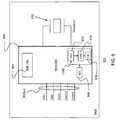
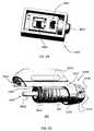
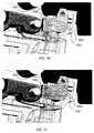
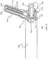
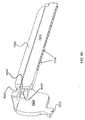
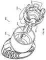
- an exemplary cordless ultrasonic surgical cautery assembly 300is shown.
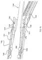
- the inventive assembly 300can be described as including three main component parts: (1) a battery assembly 301; (2) a handle assembly 302 with an ultrasonic-cutting-blade-and-waveguide assembly 304 (only a proximal portion of which is illustrated in FIG. 3 ; see FIG. 8 ); and ( 3 ) a transducer-and-generator (“TAG”) assembly 303.
- the handle assembly 302 and the ultrasonic-cutting-blade-and-waveguide assembly 304are pre-coupled but rotationally independent from one another.
- the battery assembly 301is a rechargeable, reusable battery pack with regulated output. In some cases, as is explained below, the battery assembly 301 facilitates user-interface functions.
- the handle assembly 302is a disposable unit that has bays or docks for attachment to the battery assembly 301, the TAG assembly 303, and the ultrasonic-cutting-blade-and-waveguide assembly 304.
- the handle assembly 302also houses various indicators including, for example, a speaker/buzzer and activation switches.
- the TAG assembly 303is a reusable unit that produces high frequency mechanical motion at a distal output.
- the TAG assembly 303is mechanically coupled to the ultrasoniccutting-blade-and-waveguide assembly 304 and, during operation of the device, produces movement at the distal output of the ultrasonic-cutting-blade-and-waveguide assembly 304, i.e., the cutting blade.
- the TAG assembly 303also provides a visual user interface, such as, through a red/green/blue (RGB) LED or other display. As such, a visual indicator of the battery status is uniquely not located on the battery and is, therefore, remote from the battery.
- RGBred/green/blue
- the present invention's ability to provide all of the necessary components of an ultrasonic cutting tool in a hand-held packageprovides a great advantage over prior-art devices, which devices house substantially all of the device components within a very expensive and heavy desktop box 202, as shown in FIG. 2 , and include an expensive tether 208 between the device's handpiece 112 and the desktop box 202, which, most significantly, is bulky and interferes with the surgeon's movements. Furthermore, the cord 208 must transit between the sterile field, where the device is present, and the non-sterile area where the generator rests. This sterile-to-non-sterile connection increases the risk of contamination of the sterile field and blurs the boundary between sterile and non-sterile.
- the three components of the handheld ultrasonic surgical cautery assembly 300are advantageously quickly disconnectable from one or more of the others.
- Each of the three components of the systemis sterile and can be maintained wholly in a sterile field during use. Because each portion can be separated from one or more of the other components, the present invention can be composed of one or more portions that are single-use items (i.e., disposable) and others that are multi-use items (i.e., sterilizable for use in multiple surgical procedures).
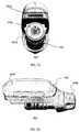
- FIGS. 4 and 5show the battery assembly 301 and TAG assembly 303 components, respectively, separate from the overall composite assembly shown in FIG. 3 . The details of each of the components are shown and described throughout the remainder of the specification.
- each of the components 301, 302/304, 303is substantially equivalent in overall weight; each of these components 301, 302/304, 303 is balanced so that they weigh substantially the same.
- the handle 302overhangs the operator's hand for support, allowing the user's hand to more freely operate the controls of the device without bearing the weight. This overhang is set to be very close to the center of gravity.
- the overall handheld ultrasonic surgical cautery assembly 300advantageously provided with a center of balance that provides a very natural and comfortable feel to the user operating the device. That is, when held in the hand of the user, the overall assembly 300 does not have a tendency to tip forward or backward or side-to-side, but remains relatively and dynamically balanced so that the waveguide is held parallel to the ground with very little effort from the user. Of course, the instrument can be placed in non-parallel angles to the ground just as easily.
- FIG. 6provides a general block circuit diagram illustrating the communicative coupling between the battery assembly 301, the handle assembly 302, and the TAG assembly 303.
- FIG. 6also shows various power and communication signal paths 601a-n between the battery assembly 301 and the handle assembly 302.
- the handle assembly 302provides additional power and communication signal paths 602a-n that continue on to the TAG assembly 303.
- These power and communication signal paths 601a-nfacilitate operation, to name a few, of:
- the above-described power and communication signal paths 601a-nare provided through a flex circuit that spans between a first multi-lead handle terminal assembly on the handle assembly 302 (where the battery assembly 301 electrically couples to the handle assembly 302) and a second multi-lead handle terminal assembly on the handle assembly 302 (where the TAG assembly 303 electrically couples to the handle assembly 302).
- the flex circuitelectrically connects the battery assembly 301 to the TAG assembly 303.
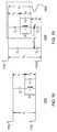
- FIG. 7provides a general block circuit diagram illustrating battery assembly 301 and internal components included therein.
- the battery assembly 301generally includes one or more battery cells 701, a battery protection circuit 702, and a battery controller 703.
- Various power and signal paths 704a-nrun between the battery cells 701 and the battery protection circuit 702.
- Power and communication signal paths 706a-nrun between the battery protection circuit 702 and the battery controller 703.
- the power and signal paths 704a-n and 706a-ncan be simple direct connections between components or can include other circuit elements not shown in the figures.
- the power and communication signal paths 706a-ninclude, among others:
- the battery cells 701include, in one embodiment, a 4-cell lithium-ion polymer (LiPoly) battery.
- LiPolylithium-ion polymer
- manufacturerscan produce LiPoly batteries in almost any shape that is necessary. These types of batteries, however, must be carefully controlled during the charging process, as overcharging LiPoly batteries quickly causes damages to the cells. Therefore, these batteries must be charged carefully. For this reason, the present invention utilizes an inventive battery protection circuit 702.
- the battery protection circuit 702controls charging and discharging of the battery cells 701 and provides battery protection and "fuel gauge" functions, i.e., battery power monitoring. More particularly, the battery protection circuit 702 provides over-voltage, under-voltage, over-temperature, and over-current monitoring and protection during both the charging and discharging stages. If overcharged, LiPoly batteries cannot only be damaged but can also ignite and/or vent.
- the battery protection circuit 702provides multiple levels of protection. For example, the battery protection circuit could provide a triple level of protection for each of current, voltage and temperature. The protection is redundant and uses active components for the first and second levels of protection, and uses passive or redundant components for the higher third level of protection. In one example, the multiple levels of protection provided by the battery protection circuit may utilize components that join the battery cells together, such as PTC devices, thermal fuses, current fuses, and resettable elements.
- the "fuel gauge” function of the battery protection circuit 702limits the discharge of voltage and current, both continuous and transient, on the output of the battery assembly 301.
- the fuel gaugecan limit the current level fed to the battery cells 701.
- a battery charging unitcan perform this current-limiting function.
- the fuel gaugealso monitors temperature and shuts down the battery assembly 301 when a temperature of the battery cells 701 exceeds a given temperature.
- the fuel gaugeis further able to determine how much total energy is left in the battery cells 701, to determine how much previous charge has been received, to determine an internal impedance of the battery cells 701, to determine current and voltage being output, and more.
- the present inventionis able to determine the "State-of-Charge" (SOC) of the battery cells 701 based in part on the chemical attributes of the battery cells 701 and, in particular, to identify when there is not enough battery capacity to safely perform a surgical procedure as described in further detail below.
- SOCstate-of-Charge
- the systemhas been programmed to include information regarding how much energy is needed to complete one cutting and cautery procedure safely. With that information stored, the fuel gauge compares that minimum amount of energy needed to the current state of charge of the battery when initially powered to begin a cut/cauterization or at a time during a procedure when a new cut/cauterization is to be performed. If the minimum threshold is not met (e.g., 1000 joules), then the device is not permitted to continue operating.
- a good indicator of the SOCis the cell voltage.
- cell voltageis monitored and the amount of current delivered to each cell is adjusted until the voltage of all cells is equalized. At this point, the cells are balanced.
- a thermistormay be installed in the battery pack and located adjacent the battery cells (e.g., either in between two cells, in between all adjacent cells, or next to cells on any side) to provide an external device (e.g., a battery charger) with a measurement or way to monitor the cell temperature within the battery pack.
- an external devicee.g., a battery charger
- FIG. 11is a general block circuit diagram illustrating the internal components of the battery controller 703 of FIG. 7 .
- the battery controller 703is fed signals and powered through power and communication signal paths 706a-n. Additionally, the battery controller 703 also provides output power and signals along power and communication signal paths 601a-n.
- the battery controller 703,according to one exemplary embodiment of the present invention, includes a power supply 1102, SMBus isolation switch(es) 1104, a microcontroller 1106, an audio driver 1108, a user buttons interface 1110, a serial communications transceiver 1112, and a buck converter 1114.
- the power supply 1102is composed of two subsystems: a buck switching power supply that first reduces the unregulated cell voltage to a substantially constant direct-current voltage, e.g., 4 VDC.
- a second linear power supplysteps down and regulates the direct-current voltage to a level that is required by the low voltage components used in this device, e.g., 3.3 VDC.
- This two-step voltage reductionis implemented to ensure low battery consumption.
- Switching power suppliesare inherently efficient, as compared to the traditional linear power supplies, but they tend to produce large output voltage ripple (noise), which could be problematic. Therefore, the voltage is first stepped down using an efficient switching regulator and is then fed to a linear regulator, which produces a better filtered and noise-free voltage to the digital components of the circuit.
- the output from the switching regulatoris also used to feed the audio amplifier, which requires larger voltages and tends to generate additional noise -- which is undesirable in the digital section of the circuit.
- the SMBus isolation switches 1104are provided as a way to prevent voltages originating from the operation of the battery protection and charge control circuit, which is ON during the charge process, to be fed into the rest of the battery circuit, which is OFF during the charge process.
- the switches usedare optically driven and turned on by the PRESENT circuit in the device (see 601a-n).
- Microcontroller 1106is a highly-integrated processing unit that controls the functions of the battery controller 703.
- the microcontroller 1106stores and executes the software that allows operation of the device.
- the microcontroller 1106is state of the art, for example, including two independent microcontroller cores in one package.
- a main coreruns a main program, which controls the device.
- sampling of the various parameters required to ensure proper and efficient operationare monitored by a second core, for example, the Control Law Accelerator (CLA) 1116, shown in FIG. 11 .
- the CLAalso can be used to provide proportional-integral-derivative ("PID”) control loop operation, which is very computationally demanding.
- PIDproportional-integral-derivative
- the microcontroller 1106lends itself to low power consumption applications and, therefore, a 3.3 volt unit can be used. Internal oscillators allow device startup without the need of external (and power consuming) components.
- the microcontroller 1106can also be configured to have its own internal non-volatile memory section to store program and diagnostic information.
- the battery microcontroller 1106monitors input voltage, output voltage, output current, and the battery and buck temperatures to provide total control of the voltage converter functions.
- Audio driver 1108produces a signal that ultimately drives the buzzer 802 that is located in the handle assembly 302.
- the audio driver 1108is a simple, but powerful, two-stage class A square wave amplifier.
- the amplifieris fed directly from the buck switching power supply (e.g., 4 VDC) to ensure maximum power capability.
- the amplifieris able to drive an audio speaker (no internal driver). Feeding the audio driver 1108 from the buck switching power supply also insures that noise generated by the audio amplifier is not fed to the supply rail of the digital and analog components of the device, which ensures noise-free operation. Capability to regulate volume by changing a single resistor is provided in case adjustment is necessary.
- the user buttons interface 1110conditions the signals received from the minimum 804 and maximum 806 activation switches housed within the handle assembly 302.
- the user buttons interface 1110is operable to continuously measure impedance of the activation switches to prevent false activation, for example, in the case of fluid ingress at the button.
- the battery controller 703measures the impedance of the switch(es) and will not activate the system until the impedance detected falls below a predetermined threshold. This configuration eliminates accidental activations due to fluid ingress, which are generally detected as higher impedances in the switch(es) than that of a fully closed switch.
- the PRESENT lineworks on a similar principle, ensuring that the PRESENT line is closed through a low enough impedance before the battery is turned on.
- the user buttons interface 1110operates in this exemplary embodiment by injecting a known current level through the switch lines.
- the current sourceWhen the button is open (no activation) the current source will maximize its voltage output and this voltage is measured by the microcontroller 1106.
- the switchWhen the switch is closed, the current source will adjust its voltage output to generate its target programmed current. If the button is working at optimally low impedance, the voltage output will be low. However, in the case where fluid enters the button, the impedance seen by the current source will be high, and a proportionally equivalent voltage, higher than that generated for a closed button, will indicate to the microcontroller 1106 that activation should not occur.
- the exemplary embodiment of the circuitryis equipped with a calibrated current source, which can be used to calibrate the programmable current source during startup and to provide a tighter detection window.
- This calibrationthat occurs during the device startup narrows the window or impedance range in which a positive activation is detected.
- the calibrationis performed by switching the circuitry of the impedance circuit to a precision current source and measuring the voltage to calibrate the circuit.
- the battery controllercan self-calibrate the activation button impedance detection circuitry to reduce the impedance range required to discern between a true button closure (activation) and an inadvertent activation signal that is erroneously caused by fluid contamination of the button(s).
- RV/I
- the first switchconnects the microcontroller serial communication lines to the programmable current source to be able to control the current source.
- the second switchconnects the output of the current source to a set of precision resistors.
- the current flowis adjusted by the microcontroller until a given voltage measurement (i.e. calibration value) is achieved. Once adjusted, the first switch is changed to connect the microcontroller to the SMBus lines and the second switch connects the current source to the activation button(s) to resume normal operation.
- the microcontrollercan switch the SMBus lines to be connected to the analog switch or to the main SMBus line. This allows the switch (non SMBus) to function and, at the same time, allows the microprocessor to connect to the SMBus lines.
- the serial communications transceiver 1112allows the battery 301 to establish communication with the TAG 303 and external devices that can be used to obtain diagnostic or calibration information from the device.
- the serial communications transceiver 1112provides transmission and reception of differential half-duplex communications between the battery controller 703 and the generator 904.
- the transceiver 1112is capable of detecting loss of hardware connection for fault detection in addition to the explained software fault detection.
- An exemplary embodiment of the device usedis configured to be compatible with USB communications for reliability and it can be used in a differential mode for common-mode noise rejection. Given the amount of data that the battery 301 exchanges with the TAG 303, a full-speed device is used (e.g., up to 12 Mbit/s).
- the systemcan issue a fault condition when a stuck switch condition exists.
- a fault conditioncan include when the high/low activation switch is improperly in the activated position at system start up, or where the high activation switch is activated but the low activation switch has not been activated, or where the high/low activation switch is in the activated position at the end of a use cycle.
- Other fault conditionsexist when there is insufficient motional feedback or when the waveguide tip is in a stalled condition. Both low amplitude displacement and high amplitude displacement can cause a shutdown if detected.
- Various faultsare associated with the TAG.
- a fault conditionexists where the output voltage is greater than a defined voltage limit.
- Another fault conditionexists when the microprocessor temperature is greater than a given predefined range, for example, greater than approximately 100 degrees Celsius.
- Another faultoccurs when the battery controller does not receive proper acknowledgement from the TAG either before, during ultrasonic start, or after ultrasonic start.
- Some fault conditionsare associated with the battery. For example, if the battery charge is below any number of predefined thresholds or if a load requires more power than the system can deliver and the amplitude drops below the desired threshold, faults can be indicated.
- Other faults of the batterycan include a failure of the battery's communications system, an over-temperature condition of the battery's microprocessor, fuel gauge, and/or regulator.
- Failure of the communications systemcan be through either or both of the TAG and battery. General faults of the system can be included as well. If the CLA ceases to function or functions inappropriately, a fault can be indicated. Failure to reset timers associated with the battery and the TAG can also indicate faults. Software failures also can trigger faults.
- the buck converter 1114provides step down voltage control to provide amplitude regulation.
- the buck converter 1114steps down the battery voltage to produce a lower voltage for delivery to the TAG assembly 303 for generation of the ultrasound output signal to the transducer 902.
- the microcontroller 1106controls the output of the buck regulator by varying or modulating the pulse widths of the input signals to the buck converter (i.e., pulse width modulation (PWM)). Off-phase PWM inputs are used for minimal output ripple.
- PWMpulse width modulation
- the deviceoperates at 300 KHz for high efficiency using small inductors and capacitors.
- the buck converter 1114is of a multi-phase synchronous design for maximum possible efficiency. The design utilizes high integrated components for small size and power consumption.
- the deviceincludes internal current protection, output current sensing, output and input voltage sensing and over-temperature protection.
- the buck converter 1114is capable of reacting at high speeds and step down voltages in the range of 2 VDC to 10.5 VDC.
- the power supply 1102produces various voltage levels at its output, which are used to power the various battery controller components shown in FIG. 11 .
- the SMBus isolation switch(es) 1104is/are used to disconnect the SMBus lines to the battery protection printed circuit board during charging and when the bus is used for other purposes within the battery controller.
- the battery controller 703facilitates a user interface, e.g., a buzzer 802 and RGB LEDs 906, and converts the output voltage and current output of the buck converter 1114, which output powers the TAG assembly 303 through at least one voltage output path (V out ) 601 a-n.
- a user interfacee.g., a buzzer 802 and RGB LEDs 906
- V outvoltage output path
- FIG. 8is a general block and schematic circuit diagram illustrating the handle assembly 302 shown in FIG. 3 .
- the handle assembly 302receives control and power signals over attached power and communication signal paths 601a-n.
- a second set of power and communication signal paths 602a-nconnect to the TAG assembly 303 when it is attached to the handheld ultrasonic surgical cautery assembly 300.
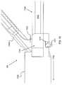
- the handle assembly 302houses the ultrasonic waveguide assembly 304 and provides a portion of the pistol grip that the operator uses to grasp and operate the entire handheld ultrasonic surgical cautery assembly 300 using, for example, a two-stage switch of button 4608 and trigger 4606 (as introduced in FIG. 46 ).
- the handle assembly 302is provided with a speaker/buzzer 802 capable of receiving a buzzer output signal from the battery assembly 301 through a signal path 601a-n and of producing an audible output, e.g., 65db, suitable for communicating specific device conditions to an operator. These conditions include, for example, successful coupling of assembly components (e.g., battery assembly 301 to handle assembly 302), high, low, or normal operation mode, fault conditions, low battery, device overload, mechanical failure, electrical failure, and others.
- the handlealso includes a Min. Button switch 804 and a Max.
- Button switch 806that, when activated, connects the respective button to ground (for example), which in an exemplary embodiment signals the battery controller to start the ultrasonic output in either low or high displacement mode.
- the handle assembly 302also provides a pass-through interconnect for signals between the battery assembly 301 and the TAG assembly 303.
- the speaker/buzzer 802 and the Min. and Max Button switches 804, 806are all part of the flex circuit of the handle assembly 302.
- the buzzer 802is held in place within the handle assembly 302 with the use of an extra tab of flex material that protrudes outward past the edge of the buzzer 802. This tab 10802 can be seen in FIGS. 108 and 110 .
- the handle assembly 302includes a slot 11002 configured to receive the flexible tab 10802 of material during assembly.
- the buzzer 802is protected from fluid ingress by a buzzer seal, for example, an acoustically transparent mesh with adhesive on both sides that bonds the buzzer into the handle assembly 802 while still allowing sound to exit and prevent fluid from entering into the buzzer 802.
- a buzzer sealfor example, an acoustically transparent mesh with adhesive on both sides that bonds the buzzer into the handle assembly 802 while still allowing sound to exit and prevent fluid from entering into the buzzer 802.
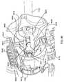
- FIG. 9is a block and schematic circuit diagram illustrating the TAG assembly 303 of FIGS. 3 and 5 , which houses the transducer 902 and the generator 904.
- the generator 904converts DC power from the battery controller 703 into a higher-voltage AC signal that drives the transducer 902, which converts the electrical signal into mechanical motion.
- FIG. 10is a block circuit diagram illustrating the internal components of the generator 904.
- the generator 904includes a power supply 1002, a serial communications transceiver 1004, a microcontroller 1006, a numerically controlled oscillator ("NCO") 1008, a push/pull switching amplifier 1010, an output filter/matching network 1012, a motional bridge 1014, a feedback amplifier and buffer(s) 1016, an LED driver 1018, and indicators 906 (for example, RGB LEDs).
- the power supply 1002receives power from the battery assembly 301 through lines Vbatt and GND of the power signal paths 602an and outputs various voltages that are used to power the generator 904.
- the serial communications transceiver 1004provides transmission and reception communications between the battery controller 703 and the generator 904, here, through a serial data link Comm+/Comm- of the communication signal paths 602a-n, although this communication can occur through a single line or through a number of lines, in series or in parallel.
- the microcontroller 1006is a highly integrated processing unit that controls the functions of the generator 904 and is one of two microcontrollers in the system, the other being part of the battery controller 703.
- a serial data linkexists between the two microcontrollers 1006, 1106 so they can communicate and coordinate their operation.
- the microcontroller 1006 in the TAG 303controls generation of the high-voltage waveform driving the piezoelectric transducer 902.
- the microcontroller 1106 in the battery assembly 301controls conversion of the DC voltage from the battery cells 701 to a lower DC voltage used by the TAG 303 when generating the high voltage AC to the transducer 902.
- the battery microcontroller 1106regulates the DC output of the battery assembly 301 to control the amplitude of the mechanical motion, and the TAG microcontroller 1006 controls the frequency of the signal that drives the transducer 902.
- the battery microcontroller 1106also handles the user interface, and the battery protection circuit 702 monitors the battery cells 701 during system operation.
- the microcontroller 1006 in the TAG 303has a variable speed system clock that is adjusted constantly while the device is running in the high-power state in order to keep the microcontroller 1006 synchronized with the ultrasonic motion.
- the microcontroller 1106 in the battery assembly 301runs at a fixed frequency while in the high-power state, regardless of the TAG clock. Because the system clock varies in frequency, a scale factor within the TAG microcontroller 1006 is changed along with the changing system clock to keep serial communication between the microcontrollers 1006, 1106 within the range of proper operation.
- Direct digital synthesisis a technique used to generate a periodic waveform with a precise output frequency that can be changed digitally using a fixed frequency source.
- the numerically controlled oscillator (“NCO”) 1008is a signal source that uses the DDS technique, which can be performed through hardware or software.
- the fixed frequency input to the DDSis used to generate a clock for the NCO 1008.
- the outputis a series of values that produce a time-varying periodic waveform. A new output value is generated during each clock cycle.
- the DDS 2200which is shown in schematic detail in FIG. 22 , works by calculating the phase component of the output waveform that is then converted to amplitude, with a new phase value being generated each clock cycle.
- the phase valueis stored in a variable register 2202, which register is referred to herein as the "phase accumulator.”
- phase accumulatorDuring each clock cycle, a fixed number is added to the number stored in the phase accumulator to produce a new phase value. This fixed number is often referred to as the frequency control word or frequency tuning word because it, along with the clock frequency, determines the output frequency.
- the value in the phase accumulatorspans one cycle of the periodic output waveform from 0 to 360 degrees, with the value rolling over at 360 degrees.
- the amplitudecan be computed using the arctangent of the phase value.
- the converterusually uses a lookup table to generate the amplitude value from the phase value.
- the output of the amplitude converteris input to a digital-to-analog converter (DAC) 2206 to generate an analog output signal f out .
- DACdigital-to-analog converter
- the analog signalis usually filtered by a band pass or low pass filter to reduce unwanted frequency components in the output waveform.
- the value in the phase accumulator 2202can be set to an integer from 0 to 359. If the frequency tuning word is 1, the value in the phase accumulator 2202 will be incremented by 1 each clock cycle. When the value reaches 359, it rolls over to zero. If the clock frequency is 360 Hz, the frequency of the output waveform will be 1 Hz. The output will, therefore, be a series of 360 points during each 1 second period of the output waveform. If the frequency tuning word is changed to 10, the value in the phase accumulator is incremented by 10 each clock cycle, and the output frequency will be 10Hz. The output will therefore be 36 points for each period of the output waveform. If the frequency tuning word is 100, the output frequency will be 100 Hz. In that case, there will be 3.6 points for each output period. Or, more accurately, some cycles of the output waveform will have 3 points and some will have 4 points, the ratio of cycles with 4 points versus 3 points being 0.6.
- the value in the phase accumulator 2202can be a 10 bit number.
- the 10 bit numberwill have 1024 possible values.
- FIG. 23illustrates the output 2300 of the DAC 2206 and what the filtered DAC output might look like.
- FIG. 24illustrates the output 2400 of the DAC 2206 and what the filtered DAC output might look like.
- the state of the NCO 1008may be undefined (or the output of the NCO 1008 may not be at a suitable frequency). This could lead to improper operation of the microcontroller.
- the NCO 1008is not used to drive the clock frequency of the microcontroller when power is first applied.
- a separate oscillatoris used. In one exemplary embodiment, the separate oscillator is integrated into the microcontroller 1006.
- the microcontrollerUsing this separate oscillator, the microcontroller initializes the various memory locations internal to the microcontroller and those in the NCO 1008. Once the NCO 1008 is operating at a suitable frequency, the microcontroller switches the source of its clock from the separate oscillator to the NCO 1008.
- FIG. 25illustrates the output 2500 of the DAC 2206 and what the filtered DAC output might look like. The output sometimes has 2 points per period and sometimes 3 points. The waveform in FIG. 25 clearly shows the need for a filter to obtain a clean sine wave.
- the push/pull switching amplifier 1010converts DC power from the battery controller 703 into a higher voltage square wave.
- the output filter/matching networkis a passive filter that changes the square wave from switching amplifier 1010 into a smooth sinusoidal wave suitable for feeding to the transducer 902.
- the motional bridge 1014is a circuit that produces a feedback signal in proportion to and in phase with the mechanical motion of the transducer 902 and waveguide assembly 304.
- the feedback amplifier and buffer(s) 1016amplifies and buffers the motional feedback signal determined within the motional bridge 1014.
- the motional bridge 1014allows the device to run with a constant displacement/amplitude mode and varies the voltage as the load varies.
- the motional bridgeis used to provide amplitude feedback and, by virtue of using this type of feedback, i.e., motional feedback, the system is able to run with constant current.
- the TAG assembly 303includes one or more red/green/blue (RGB) LEDs 906, which can be used for a variety of warning and communication purposes. For example, green can indicate the device is functioning normally whereas red indicates the device is not functioning normally. It is noted that the placement of the LEDs 906 at the generator 904 in FIG. 9 is only for illustrative purposes. The invention envisions placing the indicators anywhere at the TAG assembly 303.
- RGBred/green/blue
- the inventive handheld ultrasonic surgical cautery assembly 300provides full feedback to an operator during use to indicate a plurality of conditions associated with the ultrasonic surgical cautery assembly 300, whereby the feedback originates from the handle and not remotely.
- the speaker/buzzer 802can provide audible warnings and audible indicators of operational status of the ultrasonic surgical cautery assembly 300.
- a full class A or B amplifiere.g., a full amplifier or an ON/OFF square-pulse amplifier
- the LEDs 906can provide visual warnings and visual indicators of the operational status of the ultrasonic surgical cautery assembly 300.
- the LEDs 906can provide an indication of an amount of power remaining within the battery cell(s) 701 or a lack of sufficient power to safely carry out a surgical procedure.
- a first color of the LEDs 906indicates a fully charged battery cell(s) 701
- a second colorindicates a partially charged battery cell(s) 701.
- various blinking patterns or constant on states of the LEDs 906can provide condition indicators to the user.
- the LED driver 1018 that is shown in FIG. 10is an exemplary configuration that provides a constant current when the LEDs 906 are illuminated.
- all of the feedback indicators to the userare uniquely present on the handheld device and do not require the user to be within range of a remote feedback component that is away from the surgical field of vision or outside of the sterile field. This eliminates the requirement for the physician to shift his/her attention from the surgical field to a remote location to verify the nature of the feedback signal.
- circuitrycan be implemented in the generator or battery board(s) to provide a radio-frequency link (or other forms of communications links) for downloading, transferring or transmitting user interface, diagnostics, or other relevant data from the handheld device to the external device.
- the external deviceallows for the surgical staff or others overseeing the procedure, but who are not inside the surgical field or within the immediate vicinity of the handheld device, to receive the same relevant indications or pieces of information that are being received by the physician.
- the external devicemay also function as a valuable backup source or data log for storing information pertaining to the use and diagnostics of the handheld device.
- the external devicemay also be utilized to provide a range of more powerful data processing or software applications or tools than can reasonably be implemented in the handheld device.
- the external devicemay be able to provide analytical or diagnostic results from the information being received from the handheld device.
- the handheld device and the external devicemay also be equipped with bi-directional communication such that the external device could re-program the internal software of the handheld device or issue commands or controls to the handheld device in an advantageous manner.
- a transducer 902is an electro-mechanical device that converts electrical signals to physical movement. In a broader sense, a transducer 902 is sometimes defined as any device that converts a signal from one form to another.
- An analogous transducer deviceis an audio speaker, which converts electrical voltage variations representing music or speech to mechanical cone vibration. The speaker cone, in turn, vibrates air molecules to create acoustical energy.
- a driving wave 1400(described below) is input to the transducer 902, which then converts that electrical input to a physical output that imparts movement to the waveguide 1502 (also described below). As will be shown with regard to FIG. 15 , this movement sets up a standing wave on the waveguide 1502, resulting in motion at the end of the waveguide 1502.
- transducer 902is a piezo-electric device that converts electrical energy into mechanical motion.
- crystals in piezoelectric transducersexpand when voltage is applied.
- the crystalsare clamped into a crystal stack 5502. See also FIGS. 54 and 56 to 58 .
- a clamp bolt 5504 in this configurationacts as a spring if it is set to pre-compress the crystal stack 5502.
- the clamp bolt 5504forces the stack 5502 back to its original, pre-compressed position (i.e., it retracts).
- the clamp bolt 5504can be torqued so that there is no pre-compression on the stack 5502 and, in such a case, the bolt will still act as a spring to pull the mass back towards it original position.
- exemplary configurations of the transducercan be a so-called Langevin transducer, a bolt-clamp Langevin transducer, or a bolt-clamped sandwich-type transducer.
- a standing waveis established at the distal portion of the transducer.
- This standing waveextending along the transducer 902 and the waveguide 1502, exhibits nodes (points of minimal vibration) and anti-nodes (points of maximum vibration). Placement of the nodes and anti-nodes is important.
- the blade portion 7304is positioned at an anti-node because greatest vibratory characteristics are desired there.
- the ultrasonic waveguide couple 5004 of the transducer 902as the greatest vibratory characteristics are desired to be coupled into the waveguide 1502.
- the node(the point at which vibration movement is lowest) exists where it is secured to the TAG assembly 303. This is beneficial because imparting vibration onto/into the TAG assembly 303 is not desirable.
- a step-down in diameteris referred to as a gain-step because downstream vibratory characteristics increase as the circumferential diameter decreases.
- two gain-stepscan be seen between the crystal stack 5502 and the ultrasonic waveguide couple 5004.
- the flange 5450 of the transducer 902which is the contact point of the transducer 902 to its housing. This contact point 5450 is located at a node of the transducer 902.
- the crystal stack 5502can be displaced and, in doing so, provides a more efficient system. More specifically, by moving the crystal stack 5502 more proximally, the gain step that is adjacent to the crystal stack 5502 is moved closer to the node, thereby increasing the overall gain of the system. The required displacement of the crystals is less with greater gain. The further the crystal is away from the node the less it contributes to the power handling capability. Therefore, it is desirous to have the node within the crystal stack but also as close to the gain step as possible. When more than one crystal is placed on one side of the node they work in series, thereby increasing the total displacement.
- the crystalsdo not have to be driven so close to the maximum power and, thereby, avoids this sensitivity. It is known that higher power through dielectric losses generates heat. Such heat leads to depolling and causes a frequency shift, which can result in a change in capacitance that move the nodes away from the normal supporting point(s), causing the output to decrease and to generate unwanted heat at other unforeseen places, which can further exacerbate this problem. Furthermore, with appropriate wiring, it is possible to selectively drive only a portion of the crystal stack, which increases efficiency when the load is low.
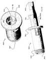
- the transducer 902 of the inventionis housed in a cylindrical casing 5430 that has an opening at the distal end to allow the horn 5002 to protrude.
- the transducer 902also has two conductive rings 5406, 5408 that surround the transducer and carry the electrical signal from the generator 904 to the transducer 902.
- the rings 5406, 5408are single machined parts that are made as a flat part either by stamping or machining that, then, has a leg bent into the correct form. Alternatively, the leg can be a second part that is pressed or soldered into a flat ring. These ring/leg sets are overmolded to a distal housing portion 5434 of the transducer housing.
- the overmoldingis not sufficient to create a gas-tight seal. Accordingly, a well is molded where the leg of the ring exits the plastic, which well can be filled with a potting material that creates the gas-tight seal. Alternatively, the leg can be a round pin. In such a case, an o-ring can be placed between the leg and the well to create the seal.
- the electrodes 5802, 5804 of the transducer crystal stack 5502can be formed to have spade or pin style connector shapes that allow the electrical connection of the transducer to the leg to happen without solder. This simplifies manufacture and eliminates exposing the leg to heat from soldering, which could further compromise the seal. Portions of the connectors are illustrated in FIGS.
- the transducer 902needs to be held by the flange 5450, which is at a node where no vibration occurs.
- the transducer 902also needs to be rotationally locked to its housing, which can be accomplished with standard key-like features shown, for example, in FIG. 55 , or can be done with four flats. By using flats, the wall thickness of the housing can be increased in the area of the contact rings, which increases the structure of this housing that will be exposed to repeated sterilization cycles.
- the support flangeis compressed against an o-ring 5452, which is supported by the distal housing portion 5434.
- a pair of hermaphroditic pushers 5454extend into the distal housing portion 5434 to allow the completion of the assembly to apply forward pressure through an elastomeric grommet.
- a pair of pusher partsis used to fit within a smaller diameter section of the horn because a single part would have to have clearance over the crystals and electrodes and, therefore, would force the overall housing diameter to be much larger.
- These pusherscan also have crush pin features to join them together to facilitate easier installation.
- the pushershave geometries that lock them rotationally into the keying features of the housing. Further keying features on the proximal end of the pushers can key the proximal housing portion 5432 onto the assembly of the transducer 902 to align clearances within the proximal housing portion 5432 with the electrodes 5402, 5404 of the transducer 902.
- proximal housing portion 5432 to the distal housing portion 5434either with adhesive or welding or other bonding measures is done with sufficient pressure to drive the pushers forward into the grommet, which, in turn, pushes on the flange 5450 and compresses the o-ring 5452 between the flange 5450 and the distal housing portion 5434 to simultaneously create a seal and support the flange 5450 with elastomers on both sides, thereby reducing acoustical coupling between the transducer 902 and the housing 5430.
- the proximal and distal housing portions 5432, 5434can be joined with threads, the tightening of the threads creating compression of the above-described stack of parts.
- Alternative embodimentscan accomplish the same result without the need to insert mold the contact rings by having other elastomeric seals between the rings 5406, 5408 and the housing 5434.
- the transducer 902is held in the TAG assembly 303 housing with a spiral ring or other retaining clip 5442 that is installed in a groove in a distal most portion of the distal housing portion 5434.
- a ring of lubricious materialsuch as PTFE, that reduces rotational friction. Reduction of friction is important in this area because it is this force-bearing surface that holds the TAG assembly 303 into the handle 302 and compresses the seal around the electrical connection between the TAG assembly 303 and the handle 302.
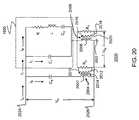
- FIG. 12is a block diagram illustrating the signal path between the battery assembly 301 and the TAG assembly 303. As described further below, the design characteristics of the signal path and the interconnecting circuit components are determined, in part, by the acute objective to protect the signal integrity and efficiency of the components at this critical, and highly vulnerable, juncture between the power source and signal-generating circuitry.
- a DC-DC step-down converter 1202steps the voltage from the battery cells 701 down from a first voltage to a second, lower voltage.
- the DC-DC step-down converter 1202includes the multi- or variable-phase (depending on the amount of power needed) buck converter 1114 and the battery microcontroller 1106, which are both shown in FIG. 11 within the battery assembly 301.
- the battery microcontroller 1106controls the buck converter 1114 to regulate the DC voltage fed to the TAG assembly 303. Together, the buck converter 1114 and the microcontroller 1106 perform the DC-to-DC conversion function in the battery assembly 301.
- a two-phase buck converter 1114is used.
- Another exemplary embodimentcan utilize a buck converter having additional phases.
- phase sheddingcan be employed.
- the number of phases usedcan change dynamically to keep the converter operating at optimal efficiency, which is a consideration for a battery powered device. In other words, when less output power is required, the power losses internal to the converter can be reduced by reducing the number of active phases.
- the generator printed circuit boardis double-sided, in that the circuitry components are found on both sides of the board.
- the power circuit componentsare installed on the top side of the PCB, the digital components are installed on the bottom of the board.
- a solid ground planeseparates the two sides.
- the DC output voltage from the battery assembly 301powers the push/pull switching amplifier 1010 in the TAG assembly 303, which assembly 303 converts the DC signal to a higher voltage AC signal.
- the TAG microcontroller 1006controls the amplifier 1010.
- the output voltage of the push pull switching amplifier 1010is, in general, a square wave, an example of which is shown in FIG. 13 , which waveform 1300 is undesirable because it is injurious to certain components, in particular, to the transducer 902.
- the abrupt rising and falling edges of a square wavecause corresponding abrupt starts and stops of the ultrasonic waveguide to produce a damaging "rattling" affect on the waveguide.
- the square wave 1300also generates interference between components. For example, higher additional harmonic frequencies of a square wave can create unwanted electrical interference and undesired operation of the circuit(s). This is in contrast to a pure sine wave, which only has one frequency.
- a wave shaping or matching circuit 1012(sometimes referred to as a "tank circuit") is introduced.
- the tank circuit 1012includes such components as, for example, an inductor, along with a capacitor in conjunction with the transducer capacitance, and filters the square wave into a smooth sine wave, which is used to drive the transducer 902 in a way that produces non-damaging ultrasonic motion at the waveguide.
- An exemplary sine wave 1400 suitable for driving the transducer 902is shown in FIG. 14 .
- the matching circuit 1012in one exemplary embodiment of the present invention, is a series L-C circuit and is controlled by the well-known principles of Kirchhoff's circuit laws.
- any matching circuitcan be used to produce a smooth sine wave 1400 suitable for driving the transducer 902.
- other driving signalscan be output from the matching circuit 1012 that are not smooth sine waves but are useful for driving the transducer 902 in a way that is less injurious than a square wave.
- the design of the power filtering circuitis such that small variations in the inductance of the power inductor will not cause the system to operate outside its specifications. This configuration reduces sensitivity to variations in tuning of the LC filter and, thereby, eliminates the need to incorporate an adjusting screw.
- the matching network 1012is tuned to match a particular transducer to which it feeds. Therefore, transducers and matching networks are best matched if they remain as a pair and are not placed in combination with another device.
- the smart battery 301could feed different frequencies to the different transducers, the frequencies being respectively matched to a particular blade in a waveguide assembly 304. Two popular frequencies for ultrasonic surgery devices are 55kHz and 40kHz.
- ferrite beadsare installed in the generator output lines or traces to block the interference from reaching the circuitry.
- the output traces of the generatorare configured to be close to one another (e.g., in a triangular double trace) and in parallel to act as a common mode for filtering out any interference (i.e., to allow maximum common mode rejection).
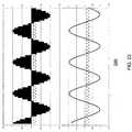
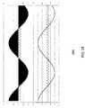
- FIG. 15is a diagrammatic illustration of the affect that a resonant sine wave input to the transducer 902 has on the waveguide 1502 of the ultrasonic cutting device.
- the sinusoidal pattern shown by the dotted lines in FIG. 15represents the amplitude of axial motion along the length of the waveguide 1502, which is coupled to the transducer 902.
- the stackexpands in a first direction 1508.
- the negative portion 1404 of the driving wave 1400shown in FIG.
- the pre-compression or the induced compression of the stackreturns the stack to its steady-state, i.e., the portion 1504 of the transducer 902 is moved in a second direction 1512.
- a smooth sine wave 1400in contrast to the square wave 1300, allows the transducer 902 and waveguide 1502 to slow before changing directions. The smoother movement is less injurious to the device's components.
- the alternating movement 1508, 1512 of the transducer portion 1504places a sinusoidal wave 1514 along the length of the waveguide 1502.
- the wave 1514alternatingly pulls the distal end 1520 of the waveguide 1502 toward the transducer 902 and pushes it away from the transducer 902, thereby longitudinally moving the distal end 1520 of the waveguide 1502 along a distance 1518.
- the tip of the waveguide 1502is considered an "anti-node,” as it is a moving point of the sine wave 1514.
- the resulting movement of the waveguide 1502produces a "sawing" movement along distance 1518 at the distal end 1520 of the waveguide 1502. (The wave 1514 and linear movement along distance 1518 are greatly exaggerated in FIG.
- This high-speed movement along distance 1518provides a cutting instrument that is able to easily slice through many materials, in particular, tissue and bone.
- the rapidly moving distal end 1520 of the waveguide 1502also generates a great deal of frictional heat when so stimulated, which heat is absorbed by the tissue that the waveguide 1502 is cutting. This heat is sufficient to cause rapid cauterization of the blood vessels within the tissue being cut.
- the driving wave 1514 traveling along the waveguide 1502is not a resonant wave, there will be no standing wave, which means that are no nodes or antinodes. This means that there is very little motion. There also exists the possibility of operating the device at an incorrect resonant frequency. Operating at the wrong resonance can produce, for example, undesirable motion such as "slapping.” In such a case, the distal end 1520 of the waveguide 1502 moves transverse to the longitudinal axis of the waveguide 1502. Any incorrect mode is not ideal and is unreliable for providing adequate cutting and surgical cautery.
- the inventionutilizes a phase locked loop (PLL) in the generator 904 to ensure that the movement 1508, 1512 of the waveguide 1502 remains resonant along the waveguide 1502 by monitoring the phase between the motional current and motional voltage waveforms fed to the transducer 902 and sending a correction signal back to the generator 904.
- the TAG microcontroller 1006controls the frequency and ensures it is in the proper range so as not to excite an undesired resonant frequency.
- the present inventioncan be provided with piezo-electric crystal stacks 1504 that are cut in varying planes, thereby creating a torsional, or twisting motion of the blade rather than only a sawing motion.
- the present inventioncan easily be adapted to a full set of uses using requiring a drilling-type motion instead of or with the sawing motion just described.
- the transducer 902 and waveguide 1502are driven at their resonant frequency. Resonance is achieved when current and voltage are substantially in phase at the input of the transducer 902. For this reason, the generator 904 uses the PLL and the signals derived from the current and voltage input to the transducer 902 to synchronize the current and voltage with one another.
- the present inventionmatches the current phase with a phase of the "motional" voltage and/or matches the input voltage phase with a phase of the "motional" current.
- a motional bridge circuitis used to measure the mechanical motion of the transducer and waveguide and to provide feedback as to the operation of the transducer and waveguide.
- the motional feedback signal from the bridgeis proportional to and in phase with the motion of the transducer 902 and waveguide 1502.
- FIG. 16is a schematic circuit diagram of a model transducer 1600, such as transducer 902, which contains piezo-electric material.
- Piezo-electric transducersare well known in the art. The mass and stiffness of the piezo-electric material creates a mechanically resonant structure within the transducer. Due to the piezo-electric effect, these mechanical properties manifest themselves as electrically equivalent properties. In other words, the electrical resonant frequency seen at the electrical terminals is equal to the mechanical resonant frequency. As shown in FIG.
- the mechanical mass, stiffness, and damping of the transducer 902may be represented by a series configuration of an inductor/coil L, a capacitor C 2 , and a resistor R, all in parallel with another capacitor C 1 .
- the electrical equivalent transducer model 1700is quite similar to the well-known model for a crystal.
- transducer current i TFlowing into an input 1610 of the electrical equivalent transducer model 1600 is a transducer current i T .
- a portion i c of i Tflows across the parallel capacitor C 1 , which is of a type and value that, for the majority of the expected frequency range, retains a substantially static capacitive value.
- the remainder of i Twhich is defined as i M , is simply i T - i c and is the actual working current.
- This remainder current i Mis referred to herein as the "motional" current. That is, the motional current is that current actually performing the work to move the waveguide 1502.
- Known prior-art designsregulate and synchronize with the total current i T , which includes i c and is not an indicator of the amount of current actually causing the motion of the waveguide 1502 by the transducer 902.
- the resistance Rincreases greatly. This increase in resistance R causes less current i M to flow through the series configuration R-L-C 2 , and more current i c to flow across capacitive element C 1 . In such a case, the waveguide 1502 slows down, degrading its performance.
- regulating the overall currentis not an effective way to maintain a constant waveguide displacement.
- one novel embodiment of the present inventionadvantageously monitors and regulates the motional current i M flowing through the transducer 902. By regulating the motional current i M , the movement distance of the waveguide 1502 can be regulated easily.
- FIG. 17is a schematic circuit diagram of an inventive circuit 1700 useful for understanding how to obtain the motional current i M of the transducer 902.
- the circuit 1700has all of the circuit elements of the transducer model 1600 plus an additional bridging capacitive element C B in parallel with the transducer model 1600 of FIG. 16 .
- the value of C Bis selected so that C 1 /C B is equal to a given ratio r.
- the chosen value for C Bshould be relatively low. This limits the current that is diverted from i M .
- the driver circuitrepresented by block 2708 and the transformer 2710 in FIG. 27 , is included in the push-pull switching amplifier 1010 of FIG. 10 .
- the driver circuitacts as a current controller and regulates the motional current i M by varying an output of the driver circuit based on the product of the current flowing through the bridge capacitance C B multiplied by the ratio r subtracted from a total current i T flowing into the transducer 902.
- sensing circuits 2714measure the motional voltage and/or motional current.
- Current and voltage measuring devices and circuit configurations for creating voltage meters and current metersare known in the art. Values of current and voltage can be determined by the present invention in any way now known or later developed, without limitation.
- FIG. 18shows another embodiment of the present invention, where the transducer 902 is schematically represented as a parallel configuration of a resistive element R, an inductive element L, and a capacitive element C 4 .
- An additional capacitive element C 3is in a series configuration between an input 1702 and the parallel configuration of the resistive element R, the inductive element L, and the capacitive element C 4 .
- This parallel representationmodels the action of the transducer in a so-called "antiresonant" mode of operation, which occurs at a slightly different frequency.
- a transducer voltage V Tis applied between the input terminals 1702, 1704 of the transducer 902.
- the transducer voltage V Tis split between a voltage V C across capacitive element C 3 and a motional voltage V M across the parallel configuration of the resistive element R, the inductive element L, and the capacitive element C 4 . It is the motional voltage V M that performs the work and causes the waveguide 1502 to move. Therefore, in this exemplary embodiment, it is the motional voltage that is to be carefully regulated.
- FIG. 19shows an exemplary embodiment of an inventive circuit configuration 1900 according to the present invention including the transducer model 1800 of FIG. 18 .
- the circuit configuration 1900adds to the transducer model 1800 three additional capacitive elements C 5 , C 6 , and C 7 .
- Capacitive element C 5is in series with the transducer model circuit 1800 of FIG. 18 while the capacitive elements C 6 and C 7 are in series with one another and, together, are in parallel with the series combination of the capacitive element C 5 and the transducer circuit model 1800.
- This circuitis analogous to a Wheatstone bridge measuring instrument.
- Wheatstone bridge circuitsare used to measure an unknown electrical resistance by balancing two legs of a bridge circuit, one leg of which includes the unknown component.
- a motional voltage V Mwhich equals V T - V C , is the unknown.
- the capacitive element C 7is selected so that its value is a ratio A of capacitive element C 3 , with A being less than one.
- the capacitive element C 6is selected so that its value is the same ratio A of the capacitive element C 5 .
- the ratio of C 5 /C 3is also the ratio A.
- V mcan be represented as simply A ⁇ V fb .
- an input voltage V inequals V T plus the voltage V B across the capacitive element C 5 .
- the feedback voltage V FBis measured from a first point located between capacitive elements C 6 and C 7 and a second point located between the transducer and the capacitive element C 5 .
- the upstream components of the TAG assembly 303act as a voltage controller and vary the power V in to maintain a constant feedback voltage V fb , resulting in a substantially constant motional voltage and maintaining a substantially constant rate of movement of the cutting blade portion of the waveguide 1502 across a variety of cutting loads.
- the present inventionis not simply regulating the input voltage V in , it is varying the input voltage V in for the purpose of regulating the motional voltage V M -- which is novel in the art.
- FIG. 20shows another exemplary embodiment of the present invention where the transducer 902 is of the circuit configuration shown in FIG. 16 .
- the configuration of FIG. 20works similarly to that shown in FIG. 17 and as described above in connection with FIG. 17 .
- a pair of transformers 2004 and 2008is used to determine and monitor the motional current I M .
- a primary winding 2002 of the first transformer 2004is in a series configuration with a bridge capacitor C B .
- a primary winding 2006 of the second transformer 2008is in a series configuration with the model transducer 1600.
- the leads 2010, 2012 of the secondary winding 2014 of the first transformer 2004are coupled through a resistor R 2 .
- the leads 2016, 2018 of the secondary winding 2020 of the second transformer 2008are coupled through a resistor R 1 .
- the first lead 2010 of the secondary winding 2014 of the first transformer 2004is directly connected to the first lead 2016 of the secondary winding 2020 of the second transformer 2008.
- the feedback voltage V fbwill always be proportional to the motional current i M .
- the upstream components of the generator 904act as a voltage controller and vary the input power (V in and I in ) to maintain a constant feedback voltage V fb , resulting in a substantially constant motional current i M and maintaining a substantially constant rate of movement of the cutting blade portion of the waveguide 1502 across a variety of cutting loads.
- the present inventionis not simply regulating the input voltage V in , it is varying the input current I in for the purpose of regulating the motional current i M -- which is novel in the art.
- An alternative embodimentwhich is not illustrated, substitutes use of the transformers 2004, 2008 with resistors.
- the capacitors C 6 and C 5can be replaced with resistors, which are used to measure the currents I b and I t .
- FIG. 21shows another exemplary embodiment of the present invention where the model transducer 1800 is modeled by the circuit configuration shown in FIG. 18 .
- the configuration of FIG. 21works similarly to that shown in FIG. 19 and as described above in connection with FIG. 19 .
- a transformer 2110is used to determine and monitor the motional voltage V M of the transducer 1800.
- a primary winding 2106 of the transformer 2110is in a series circuit configuration with an inductive element L 2 and a capacitive element C 1 .
- a voltage V inis applied across input leads 2102, 2104 of the circuit formed by the primary winding 2106 of the transformer 2110, the inductive element L 2 , and the capacitive element C 1 .
- a current through the primary winding 2106induces a corresponding current in the secondary winding 2108 of the transformer 2110.
- the secondary winding 2108 of the transformer 2110is in a parallel configuration with a combination of the transducer 1800 and a bridge capacitor C B .
- the two components forming the combinationare in a series configuration.
- the secondary winding 2108is tapped at a point 2112.
- a selectable percentage of the induced voltage on the secondary winding 2108appears from point 2112 to ground 2114.
- this circuitis analogous to a Wheatstone bridge measuring instrument.
- One legis the first secondary winding m
- the second legis the second secondary winding n
- the third legis the transducer model 1800
- the fourth legis the capacitor C B .
- the voltage V Mis the unknown.
- the value of a feedback voltagewill reflect the motional voltage V M .
- the inventioncan determine whether the motional voltage V M is changing by monitoring the feedback voltage V fb for changes.
- the transducermay be driven in the parallel resonant mode of operation, where motion is proportional to voltage.
- the advantage of this mode of operationis that the required constant-voltage-mode power supply is simpler to design and safer to operate than a constant-current-mode power supply.
- the transducerhas a higher impedance when unloaded (rather than a lower impedance when unloaded in the series-resonant mode of operation), it naturally tends to draw less power when unloaded.
- the parallel-resonant mode of operationis more difficult to maintain because the resonant bandwidth is narrower than that of the series-resonant mode and has a slightly different natural resonant frequency; hence, the mechanical components of the device must be specifically configured to operate at either the series resonant or parallel-resonant mode of operation.
- the present inventioncontrols the voltage and varies the power V in to maintain a constant feedback voltage V fb , resulting in a substantially constant motional voltage V M and maintains a substantially constant rate of movement of the cutting blade portion of the waveguide 1502 across a variety of cutting loads.
- the present inventionis not simply regulating the input voltage V in , it is varying the input voltage V in for the purpose of regulating the motional voltage V M -- which is novel in the art.
- the microcontroller 1006 in the TAG 303monitors the feedback signal through motional bridge 1014 to generate the signal that goes to the primary side of the transformer 1010.
- the TAG microcontroller 1006calculates (in the CLA 912) the phase difference between these signals and adjusts the NCO 1008 output to make the phase difference equal to zero.
- the phase and magnitude of the motional feedback signalis computed using a discrete Fourier transform (DFT).
- DFTdiscrete Fourier transform
- the phase reference for the DFT computationis the drive signal for the push-pull amplifier 1010. The frequency can be changed to cause the push-pull drive signal to be in phase with the motional feedback signal.
- the phase of the motional feedback signalis positive, it is an indication the running frequency is below the resonant frequency and the running frequency should be increased; if the phase is negative, it is an indication the running frequency is above the resonant frequency and the running frequency should be decreased; if the phase is close to zero, the running frequency is close to the resonant frequency of the transducer 902 and waveguide 1502.
- the NCO 1008(utilizing DDS) is used to alter the frequency appropriately.
- the NCO 1008outputs a clock to the CPU's external clock input at a frequency, for example, 6 times less that the operating frequency of the TAG microcontroller 1006.
- the external frequency inputis fed into the processor's Phase Lock Loop (PLL) and multiplied by a factor of 6 to obtain the CPU's SYSCLK.
- PLLPhase Lock Loop
- the NCO 1008is controlled by the processor through an SPI interface.
- the SPI interfaceis used to write a 32-bit divisor to the NCO 1008 that is used to divide the 25-MHz fixed frequency clock to obtain the desired output frequency.
- the TAGprovides synchronized operation of hardware with the oscillation frequency. In other words, to the main processor 914, it appears as though the frequency is constant, thereby simplifying the sampling and calculation of the motion feedback phase.
- Startup conditionsare different than those during steady state operation, which is described in detail in the following section.
- the waveguide 1502is initially at rest and, therefore, there is no waveguide motion. Accordingly, there is no immediate, ascertainable motional feedback signal that can be used to determine the composite resonant frequency of the transducer 902 and waveguide 1502.
- the inventive systemhas an ability to operate in a different mode during an initial startup period than during steady state.
- a startup procedure according to an exemplary embodiment of the present inventionis represented in the process flow diagram of FIG. 72 , which illustrates an interchange between the battery controller 703 and the generator 904 of the TAG assembly 303.
- the relationship between the battery controller and generatorcan be described as a "master-and-slave" relationship, as the battery controller issues all commands to the generator 904 and the generator 904 receives all of its instructions from the battery controller 703.
- the generator 904 of the TAG assembly 303could act as the "master” and issue all commands to the battery controller 703, or, the generator 904 of the TAG assembly 303 and the battery controller 703 may function as peers.
- both the battery controller 703 and the generator 904are idle at steps 7201 and 7202, respectively.
- step 7203the battery controller 703 is awakened out of its idle condition, for example, by the user squeezing the button/trigger 4608.
- the battery controller 703relays a signal, such as an "ULTRASOUND ON" command 7205, to the generator 904 using the communication lines 602a-n (i.e., Comm+/Comm-).
- the generatoracknowledges the command 7205 received from the battery controller 703 and, in return, signals a positive response 7204, such as an "ULTRASOUND ON" response, to the battery controller 703 using the communication lines 602a-n (i.e., Comm+/Comm-).
- a positive response 7204such as an "ULTRASOUND ON” response
- the battery controllerissues a fault condition at step 7207, such as a "FAILURE TO START" condition, and terminates the operation cycle at step 7209. At such time, appropriate indicators can be actuated.
- the microcontroller 1106 in the battery controller 703initiates a process for quickly and safely advancing the current rate in the TAG assembly 303 resulting in a resonant motion output from the TAG assembly 303 to the waveguide 1502. Advancement proceeds from an idle condition to a level predicted to be within a "ballpark window" for producing an ascertainable motional feedback signal and achieving a beginning resonant frequency condition. As shown in FIG. 11 , the microcontroller 1106 in the battery controller 703 has two processing units.
- a first processing unitthe Control Law Accelerator (“CLA”) 1116
- the second processing unita main processor 1118
- microcontroller 1106turns on the buck power supply 1114 and initializes the CLA 1116.
- the CLA 1116uses a proportional-integral-derivative ("PID") control algorithm to compute a new duty cycle value for the Pulse Width Modulators (“PWMs”) that are driving the two-phase buck converter 1114.
- PIDproportional-integral-derivative
- the battery controller 703starts the PWMs and begins, at step 7211, using a fast, non-linear PID control loop, to increase the output voltage of the DC-DC converter 1202.
- the increasing output voltagecauses a corresponding increase in the input current to the push/pull amplifier 1010 of the generator 904.
- the output voltageincreases, or is otherwise modified, until, at step 7219, the actual, measured input current reaches a predetermined reference current level, referred to herein as "I ref ⁇ "
- I refis a calibrated value that is predicted to create a driving wave output from the transducer 902 that will achieve a displacement of the waveguide 1502 and place the resulting amplitude near a value sufficient to reach the target resonant frequency.
- I refis initially set by the battery microcontroller 703 in step 7225. This calibrated value for I ref may be stored inside the TAG assembly 303 and read by the battery microcontroller 703 upon establishment of the communication link 7204. Simply put, I ref is a way to not overdrive the system during startup so that with low motion during startup, the system does not overreact and overshoot. I ref is the estimated current to drive the system at the target displacement. When the system gets close to target displacement, then the amplitude control takes over.
- Table 1 belowillustrates an example of a non-linear PID control loop or algorithm in accordance with the present invention, whereby the output voltage level is modified until the actual, measured input current reaches the reference current, I ref .
- the non-linear PID control loopdivides the percent error of the actual, measured input current versus the reference current I ref into 5% bins, which are shown below as constants G 0 through G n (where "n" is some number of the last step prior to reaching I ref ).
- Each binhas its own non-linear tuning coefficients (e.g., K p , K i , and K d ).
- the non-linear tuning coefficientsallow for the output voltage and, in turn, the actual input current, to initially advance quickly towards the reference current point I ref when the input current is far away from the reference current point, and then slowly reach the reference current point I ref once the input current value is close to reaching the reference current point.
- the systemis less prone to being disturbed by noise.
- the non-linear PID within the CLA 1116shapes the overshoot to no more than 15% greater than I ref . It is desirable to have the control loop maintain current but not to allow over current for any significant time; in other words, the loop must make the current retract from an overcurrent state quickly.
- the non-linear PID loop of the CLA 1116shapes the increase of the output voltage and input current in such a way that the input current advances quickly and accurately to the desired reference current level I ref , but does so in such a way that is stable and avoids a dangerous "overcurrent" condition.
- the initial signali.e., the "ULTRASOUND ON" command 7205 from the battery controller 703, received by the generator, causes the TAG microcontroller 1006 to begin its own initialization process in parallel with the operation of the battery controller 703.
- the microcontroller 1006 in the TAG assembly 303has two independent processing units: the CLA 912 and the main processor 914. Referring back to FIG.
- the TAG microcontroller 1006initializes the CLA 912 and starts the ultrasound PWMs that drive the ultrasonic frequency at a frequency within the operating frequency range of the waveguide and transducer.
- any motional feedback signal that is presentis weak and, therefore, it is desirable to use a high gain amplifier to provide a higher signal level because the signal level is initially very small.
- the amplitudei.e., the displacement of the mechanical motion
- the amplitudeis incrementing proportionally until it reaches a set point or level within 20% of a "target amplitude,” which should produce a motional feedback signal and place the TAG assembly 303 in a "ballpark window" for achieving the resonant frequency.
- the "target amplitude”is a pre-determined, safe, threshold level. It is undesirable to surpass this threshold level and, when surpassed (e.g., by 10-12%), indicates an "over-amplitude" condition that is undesirable and causes the device to initiate a fault condition and control shutdown.
- the battery controller 703closely monitors the amplitude to regulate the displacement level of the TAG assembly 303.
- the battery controller 703issues a command 7221 at frequent intervals (e.g., every 4 ms), such as an "AMPLITUDE REQ" command, to the TAG assembly 303 using at least one of the communication lines 602a-n (e.g., Comm+/Comm-).
- the battery controller 703receives a signal 7210, through at least one of the communication lines 602a-n (e.g., Comm+/Comm-), such as an "AMPLITUDE REQ" response, from the TAG assembly 303, which provides the battery controller 703 with a measurement of the displacement level of the TAG assembly 303.
- the battery microcontroller 1106, at step 7223makes one of several possible determinations based upon the displacement measurement. If the amplitude level has reached the level of within 20% of the "target amplitude" or, effectively, 80% of the "target amplitude,” in step 7227 the power control is switched from the inner, current-control loop 2601 to the outer, amplitude-control loop 2602, which is described in further detail below. If the amplitude level has not yet reached 80% of the "target amplitude,” in step 7229, the current control loop will maintain the current at the reference current level I ref until the amplitude reaches the 80% point.
- the battery microcontroller 1106terminates the operation cycle at step 7209 and issues, for example, an "ULTRASOUND OFF" command 7233 to the generator 904.
- the generator 904relays a response 7212, such as an "ULTRASOUND OFF" response, indicating that it has ceased active operation.
- the battery microcontroller 1106If the potentially dangerous condition occurs in which the amplitude level has actually surpassed the level of within 20% of the "target amplitude," the battery microcontroller 1106 immediately issues a fault condition 7235 and terminates the operation cycle at step 7209, as described above, due to this "over-amplitude" condition.
- the TAG microcontroller 1006controls the frequency of the signal that drives the transducer 902 based upon its detection of the motional feedback signal.
- the operating frequencyis set at a fixed value that is within the operating frequency range of the transducer 902 and waveguide 1502 (e.g., 55.2 kHz). If present at that set frequency, a motional feedback signal from the bridge circuit is routed to a high and low gain buffer. Each of these signals is fed into the analog-to-digital converter ("ADC") 908 of the microcontroller 1006 in the TAG assembly 303.
- ADCanalog-to-digital converter
- the high-gain, buffered-feedback signalis selected as the motional feedback signal will initially be small.
- a main function of the CLA 912is to take the output from the ADC, perform the Discrete Fourier Transform ("DFT") calculations, and pass the results to the main processor 914. Shown as step 7218, the results from the DFT calculations are the phase and magnitude of the motional feedback (“MF”) signal, as well as the real and imaginary terms for the signal.
- DFTDiscrete Fourier Transform
- a tuning loopis called once per ultrasound cycle. If, at step 7214, it is determined that a valid motional feedback signal does not exist at the set frequency, the system simply waits until there is a valid motional feedback signal. However, if a fixed period of time has been exceeded as determined by a cycle timeout timer, and there is still no valid motional feedback signal, a cycle activation limit "timeout" is triggered at step 7216 and the generator 904 turns off.
- the systememploys a high-gain-buffered A-to-D channel such that the high-gain-buffered feedback signal is selected. This allows the system to lock at a lower motional feedback signal level.
- a determination of whether or not the motional feedback signal has reached a defined "THRESHOLD" valueis made at step 7220. If the motional feedback signal has reached the defined "THRESHOLD" value, the amplitude of the motional feedback signal has increased to the point that a valid motional feedback signal has emerged from any obstructive noise such that the DFT calculations in the CLA 912 are reliable.
- the systemswitches to the low-gain channel.
- the A-to-D channelcan switch back to the high-gain channel as shown in step 7226.
- a higher resolution A/D converteris beneficially not required.
- the generator 904enters a frequency-tuning mode for locking the set frequency onto the resonant frequency of the TAG assembly 303 in parallel with the current and amplitude controls described above.
- the process for achieving resonant frequencyis not a process of sweeping for the optimum frequency, but rather is uniquely a tracking or tuning process for locking onto the optimum frequency.
- the present inventionmay also employ a frequency sweeping mode, whereby the initial operating or set frequency is chosen to be at a lower boundary of the "ballpark window" of the predicted resonant frequency and is steadily incremented until it reaches the resonant frequency or vice versa.
- the main processor 914 of the TAG microcontroller 1006uses the results of the DFT calculation (i.e., the phase and magnitude of the motional feedback signal) to control the running frequency of the generator.
- the tuning algorithmis divided into two states: STARTING and LOCKING.
- STARTING phaseat step 7230, a determination is made of whether or not the motional feedback signal has reached a defined "STARTUP THRESHOLD" value. If the motional feedback signal has reached the defined "STARTUP THRESHOLD" value, the amplitude of the motional feedback signal has increased to the point that the system can actively begin moving towards resonance at step 7232.
- step 7230determines whether the motional feedback signal has not reached the defined "STARTUP THRESHOLD" value. If the determination at step 7230 is that the motional feedback signal has not reached the defined "STARTUP THRESHOLD" value, the process moves to step 7234. At step 7234, the STARTING phase simply waits until the point is reached whereby there is a large enough motional feedback signal to allow locking.
- the sine of the phase offset between the motional feedback signal and the driving signalis used along with the differential of the sine to determine the size and direction of the frequency step to adjust the output frequency to move the system to resonance.
- the sine of the phaseis used to determine the frequency step because it is bounded by the value ⁇ 1 and closely approximates the phase value at small angles, whereas a tangent function has the undesirable, unbounded range of ⁇ ⁇ .
- a PID loopis used to calculate the frequency step in either a plus or minus direction.
- the PID loopis non-linear, whereby the value of the sine is used to determine a bin number. That bin number is used as an index to access the tuning coefficients used by the PID.
- An index tablecontains the proportional gain, the integral gain, and the differential gain.
- the entry sine value to enter a bindiffers from the value to exit a bin. This introduces hysteresis to prevent oscillations near the bin transitions.
- a non-linear PIDis used to achieve a rapid frequency lock.
- Table 2illustrates an example of a non-linear, asymmetric PID loop or algorithm in accordance with the present invention whereby the size in frequency step is staggered until it reaches the target resonance frequency, f res .
- the gain constants PID 0 through PID nare separated by non-linear increments. The gain values have been chosen to move the system toward resonance quickly when the system is far from resonance and slowly when the system is close to or at resonance.
- the value for the maximum frequency step sizeis greater than during steady state operation; it is, for example, set to 8 Hz. If the phase is positive, it is an indication that the running frequency is below the resonant frequency of the transducer and needs to be increased. If the phase is negative, it is an indication the running frequency is above the resonant frequency and the running frequency should be decreased. If the phase is close to zero, the running frequency is close to the resonant frequency of the transducer 902 and waveguide 1502.
- the numerically controlled oscillator 1008 utilizing direct digital synthesisis used to change the frequency at step 7240.
- the DDS 2200provides synchronized operation of hardware with the oscillation frequency.
- the main processor 914it appears as though the frequency is constant.
- the clock frequency of the main processor 914is a multiple of the oscillation frequency.
- the inventionalters the PWM frequency in a unique and novel way. With the invention, PWM is performed inside the main processor 914. Because of this, the present invention actually increases/decreases the frequency of the main processor 914 - which has not been done before.
- the A/D converter 908 adjustmentsare automatic as well because the A/D converter 908 exists inside the microcontroller 1006. This inventive technique can be analogized to a singer adjusting a speed of a metronome to match the singer's tempo rather than, as is conventionally done, the singer changing her/his tempo to match the metronome.
- the generator 904turns off and a fault condition is triggered, as shown in step 7242.
- Exemplary lower and upper frequency limits for the inventionare 54 kHz and 58 kHz, respectively.
- a number of various conditionscan cause the frequency to reach the minimum or maximum limit, including breakage of a component (such as the waveguide 1502) or a situation in which the waveguide 1502 is under such a heavy load that the device is not able to input the amount of power needed to find resonance.
- the objectiveis to maintain the transducer and waveguide at resonant frequency and to control the displacement in response to any drifting that occurs as a result of a load on the waveguide 1502 during use of the device.
- the transducer 902 and waveguide 1502are driven at their composite resonant frequency, they produce a large amount of mechanical motion.
- the electrical energy from the batteryis, in this state, converted into a high voltage AC waveform that drives the transducer 902.
- the frequency of this waveformshould be the same as the resonant frequency of the waveguide 1502 and transducer 902, and the magnitude of the waveform should be the value that produces the proper amount of mechanical motion.
- the displacementis approximately proportional to the transducer current, and the transducer current is approximately proportional to the input current to the push/pull amplifier 1010.
- the output voltagewill vary with a varying load. In other words, the voltage will increase if the output power requirement increases and vice versa.
- FIG. 26As described above in relation to the startup process, shown in FIG. 26 are two control loops, an inner, current control loop 2601 and an outer, amplitude control loop 2602 for uniquely regulating the amplitude of the driving wave input to the transducer 902.
- the current control loop 2601regulates the current from the battery assembly 301 going into the push/pull amplifier 1010.
- the amplitude control loop 2602compensates for load differences or any other changes that occur in the transducer and/or waveguide. To accomplish this goal, the amplitude control loop 2602 utilizes the motional feedback signal to generate the desired reference current level, "I ref ,” that is used by the current control loop 2601 to alter the output voltage of the DC-DC converter as described above.
- I refdesired reference current level
- the current control loop 2601operates at a higher frequency than the amplitude control loop 2602, e.g., approximately 300 KHz.
- the amplitude control loop 2602typically operates, for example, at a frequency of 250 Hz.
- the present amplitude valueis subtracted from the desired "target amplitude" to generate an amplitude percent error signal.
- This amplitude percent error signalis the input into the PID control algorithm of the amplitude control loop 2601 for generating the new, desired reference current level "I ref ,” based upon the operating conditions being experienced by the transducer 902 and waveguide 1502 at that particular time.
- the amplitude control loop 2602changes the target or reference current value for the CLA 912 of the current control loop 2601 to reach the desired amplitude based on the percent error calculation. In this way, the output power is altered based on the variable need of the transducer 902 and waveguide 1502.
- the main processor 1118 of the battery controller 703checks the new reference current value to make sure that it is not greater than the maximum output current value.
- the current control loop 2601proceeds to change the output voltage and input current to the push/pull amplifier 1010.
- a measurement of the actual current level 2603 of the battery pack outputis fed into the ADC 1120 of the battery microcontroller 1106 (shown in FIG. 11 ).
- the CLA 1116takes the value from the ADC 1120 and subtracts it from the target or reference input current level I ref to generate the current error signal.
- the CLA 1116uses the PID control algorithm to compute a new duty cycle value for the PWMs that are driving the two-phase buck converter 1114.
- the CLA 1116also computes a maximum PWM duty cycle to limit the output voltage.
- the algorithm to compute the maximum duty cycleuses the measured battery voltage and assumes the buck converter 1114 is operating in continuous conduction mode.
- the present inventionuniquely allows for finely adjusting the output of the transducer based on the motional feedback signal, achieving a more precise amplitude control.
- the use of a current control loopallows for faster initial response that would not be possible with amplitude control alone.
- having the two loopsprovides for redundancy and individual calibration of the transducer and generator during manufacture. This "amplitude calibration factor" is critical for dialing out a variation in the electrical and mechanical variations in the transducer/piezoelectric crystals and for adjusting for variation in the electrical components of the generator magnitude feedback system.
- the feedback voltageis converted with this calibration factor to result in a magnitude value that is directly related to displacement.
- this calibration valueis adjusted while measuring the actual system output displacement. This adjustment pairs a given transducer and generator together so that, as a system, they will develop the proper displacement. Defaults for this value is intentionally set low as a safety mechanism should the adjusted values be lost, corrupted, or inadvertently not programmed. In this way, the default displacement will be lower than the target, resulting in slower but still effective tissue performance.
- This calibration schemesimplifies manufacturing and reduces the burden of controlling tolerances of the transducer and the generator.
- the capacitance of the transducer and the coupling coefficientwill shift and the displacement of the system will decline slightly.
- This change in temperaturealso comes with a shift in frequency.
- By monitoring the frequencyit is possible to provide an offset to more tightly control the displacement through heavy use. This can be accomplished with a comparison to the frequency at startup or to an absolute frequency reference. Alternatively, other measurable characteristics of the transducer can be used to control this offset. Alternatively, the amount of energy put into the transducer can be used to estimate the change and adjust accordingly.
- the main processor 914 of the generator 904uses the results of the DFT calculation to adjust the running frequency of the generator 904 based on the phase of the motional feedback signal in order to maintain a resonant frequency during steady state operation.
- the motional feedback signal from the bridge circuitis proportional to and in phase with the motion of the transducer 902 and waveguide 1502.
- the phase and magnitude of the motional feedback signalis computed using a Discrete Fourier Transform ("DFT").
- the phase reference for the DFT computationis the drive signal for the push/pull amplifier 1010.
- the frequencyis, then, simply changed to cause the push/pull drive signal to be in phase with the motional feedback signal.
- the DFT calculationis simplified and made more accurate if the ADC sample time interval is exactly an integer multiple of the output frequency period.
- This techniqueis referred to herein as "coherent sampling.”
- the signalsare sampled 12 times per output cycle such that the CLA 912 is sampling the motional feedback signal at 12 times the ultrasonic frequency.
- coherent samplingthere are exactly 12 samples per cycle with each occurring at the same point in time relative to the phase of the drive signal.
- the ADC sample clockis generated internally in the TAG microcontroller's 1006 system clock 916. Accordingly, for coherent sampling, the system clock 916 needs to be synchronized to the output.
- the PWM signal driving the metal-oxide field-effect transistors (MOSFETs) that, in turn, generate the output waveform,is also generated internally from the system clock 916.
- MOSFETsmetal-oxide field-effect transistors
- One exemplary embodiment of the present inventiongenerates the system clock 916 from the DDS 1008.
- the system clock 916also changes.
- the two PWM outputsemploy a deadband to ensure that both MOSFETs are never activated at the same time.
- FIG. 27shows a simplified block circuit diagram illustrating another exemplary electrical embodiment of the present invention, which includes a microprocessor 2702, a clock 2730, a memory 2726, a power supply 2704 (e.g., a battery), a switch 2706 (e.g., a MOSFET power switch), a drive circuit 2708 (PLL), a transformer 2710, a signal smoothing circuit 2712 (also referred to as a matching circuit and can be, e.g., a tank circuit), a sensing circuit 2714, a transducer 902, and a waveguide assembly 304, which terminates at an ultrasonic cutting blade 1520, referred to herein simply as the waveguide 1502.
- a signal smoothing circuit 2712also referred to as a matching circuit and can be, e.g., a tank circuit
- a sensing circuit 2714e.g., a transducer 902
- a waveguide assembly 304which terminates at an ultrasonic cutting blade 1520,
- One feature of the present invention that severs dependency on high voltage (120 VAC) input poweris the utilization of low-voltage switching throughout the wave-forming process and the amplification of the driving signal only directly before the transformer stage. For this reason, in one exemplary embodiment of the present invention, power is derived from only a battery, or a group of batteries, small enough to fit either within the handle assembly 302. State-of-the-art battery technology provides powerful batteries of a few centimeters in height and width and a few millimeters in depth.
- the output of the battery 2704is fed to and powers the processor 2702.
- the processor 2702receives and outputs signals and, as will be described below, functions according to custom logic or in accordance with computer programs that are executed by the processor 2702.
- the device 2700can also include a main memory 2726, preferably, random access memory (RAM), that stores computer-readable instructions and data.
- main memory 2726preferably, random access memory (RAM)
- the output of the battery 2704also is directed to a switch 2706 having a duty cycle controlled by the processor 2702.
- the processor 2702By controlling the on-time for the switch 2706, the processor 2702 is able to dictate the total amount of power that is ultimately delivered to the transducer 2716.
- the switch 2706is a MOSFET, although other switches and switching configurations are adaptable as well.
- the output of the switch 2706is fed to a drive circuit 2708 that contains, for example, a phase detecting PLL and/or a low-pass filter and/or a voltage-controlled oscillator.
- the output of the switch 2706is sampled by the processor 2702 to determine the voltage and current of the output signal (labeled in FIG.
- AD2 V ln and AD3 I lnare used in a feedback architecture to adjust the pulse width modulation of the switch 2706.
- the duty cycle of the switch 2706can vary from about 20% to about 80%, depending on the desired and actual output from the switch 2706.
- the drive circuit 2708which receives the signal from the switch 2706, includes an oscillatory circuit that turns the output of the switch 2706 into an electrical signal having a single ultrasonic frequency, e.g., 55 kHz (referred to as VCO in FIG. 27 ). As explained above, a smoothed-out version of this ultrasonic waveform is ultimately fed to the transducer 902 to produce a resonant sine wave along the waveguide 1502.
- VCOultrasonic frequency
- a transformer 2710that is able to step up the low voltage signal(s) to a higher voltage. It is noted that all upstream switching, prior to the transformer 2710, is performed at low (i.e., battery driven) voltages, something that, to date, has not been possible for ultrasonic cutting and cautery devices. This is at least partially due to the fact that the device advantageously uses low on-resistance MOSFET switching devices. Low on-resistance MOSFET switches are advantageous, as they produce lower switching losses and less heat than a traditional MOSFET device and allow higher current to pass through. Therefore, the switching stage (pre-transformer) can be characterized as low voltage/high current.
- the MOSFET(s)are run, for example, at 10 V.
- a separate 10 VDC power supplycan be used to feed the MOSFET gate, which ensures that the MOSFET is fully on and a reasonably low on resistance is achieved.
- the transformer 2710steps up the battery voltage to 120V RMS. Transformers are known in the art and are, therefore, not explained here in detail.
- circuit component degradationcan negatively impact the entire circuit's performance.
- One factor that directly affects component performanceis heat.
- Known circuitsgenerally monitor switching temperatures (e.g., MOSFET temperatures).
- MOSFET temperaturesare no longer a valid indicator of circuit loads and heat.
- the present inventionsenses with a sensing circuit 2714 the temperature of the transformer 2710. This temperature sensing is advantageous as the transformer 2710 is run at or very close to its maximum temperature during use of the device.
- the present inventioncan respond to a maximum temperature of the transformer 2710 by, for example, reducing the driving power in the transformer 2710, signaling the user, turning the power off completely, pulsing the power, or other appropriate responses.
- the processor 2702is communicatively coupled to the end effector 118, which is used to place material in physical contact with the blade portion 116 of the waveguide 114, e.g., the clamping mechanism shown in FIG. 1 .
- Sensorsare provided that measure, at the end effector, a clamping force value (existing within a known range) and, based upon the received clamping force value, the processor 2702 varies the motional voltage V M .
- a temperature sensor 2736can be communicatively coupled to the processor 2702, where the processor 2702 is operable to receive and interpret a signal indicating a current temperature of the blade from the temperature sensor 2736 and to determine a target frequency of blade movement based upon the received temperature.
- the PLL 2708which is coupled to the processor 2702, is able to determine a frequency of waveguide movement and communicate that frequency to the processor 2702.
- the processor 2702stores this frequency value in the memory 2726 when the device is turned off.
- the processor 2702is able to determine an elapsed time after the device is shut off and retrieve the last frequency of waveguide movement if the elapsed time is less than a predetermined value. The device can then start up at the last frequency, which, presumably, is the optimum frequency for the current load.
- FIG. 28shows an exemplary embodiment of the battery assembly 301 separate from the handle assembly 302.
- the battery assembly 301includes an outer shell 2802 that comprises a first half 2802a and a second half 2802b. There is, however, no requirement that the shell 2802 be provided in two halves.
- the first half 2802acan be ultrasonically welded to the second half 2802b in a clamshell configuration. Ultrasonically welding the two halves of the shell 2802 eliminates the need for gaskets while providing a "hermetic" seal between the components within the shell 2802 and the environment.
- a “hermetic" sealindicates a seal that sufficiently isolates a compartment (e.g., interior of the shell 2802) and components disposed therein from a sterile field of an operating environment into which the device has been introduced so that no contaminants from one side of the seal are able to transfer to the other side of the seal.
- This sealis at least gas-tight, thereby preventing intrusion of air, water, vapor phase H 2 O 2 , etc.
- room airwill be trapped in the enclosure with whatever moisture is present. This can easily be more moisture than is desirable in an electronics enclosure. Therefore, inclusion of a desiccant system inside the enclosure can serve two purposes.
- a primary purposeis to absorb any moisture that may ingress over the life of the device, but, if sized appropriately, the desiccant system will also serve to absorb any moisture that is trapped during assembly. Use of the desiccant system, therefore, simplifies assembly and eliminates the need to close the enclosure under any special environments.
- FIG. 28also shows a multi-lead battery terminal assembly 2804, which is an interface that electrically couples the components within the battery assembly 301 to an electrical interface of the handle assembly 302. It is through the handle assembly 302 that the battery assembly 301 is able to electrically (and mechanically) couple with the TAG assembly 303 of the present invention. As is explained above, the battery assembly 301, through the multi-lead battery terminal assembly 2804, provides power to the inventive ultrasonic surgical cautery assembly 300, as well as other functionality described herein.
- the multi-lead battery terminal assembly 2804includes a plurality of contacts pads 2806a-n, each one capable of separately electrically connecting a terminal within the battery assembly 301 to another terminal provided by a docking bay (see FIG.
- FIG. 6One example of such electrical connections coupled to the plurality of contact pads 2806a-n is shown in FIG. 6 as power and communication signal paths 601a-n.
- sixteen different contact pads 2806a-nare shown. This number is merely illustrative.
- an interior side of the battery terminal assembly 2804has a well formed on the molded terminal holder that can be filled with potting materials to create a gas tight seal.
- the contact pads 2806a-nare overmolded in the lid and extend through the potting well into the interior of the battery 301.
- a flex circuitcan be used to rearrange the array of pins and provide an electrical connection to the circuit boards.
- a 4x4 arrayis converted to a 2x8 array.
- FIG. 29provides a view of the underside of an exemplary embodiment of the multi-lead battery terminal assembly 2804.
- the plurality of contact pads 2806a-n of the multi-lead battery terminal assembly 2804include a corresponding plurality of interior contact pins 2906a-n.
- Each contact pin 2906provides a direct electrical coupling to a corresponding one of the contact pads 2806.
- FIGS. 28 and 32show two hemispherical depressions 2810 in the battery casing that, when combined with the hook feature 3302, a generally longitudinal void, can be used to retain the battery 301 into a charger.
- Such geometrical featuresare easy to fabricate and easy to clean and provide a simple way to capture the battery 301 in a charger in a way that does not require the releasing mechanism that normally is used to disconnect the battery 301 from the handle 302.
- FIG. 29provides a view of the multi-lead battery terminal assembly 2804 positioned inside an upper portion of the first shell half 2802a of the battery assembly 301.
- an upper portion of the first shell half 2802aforms a mouth 2902 that accepts an outer peripheral edge 2904 of the multi-lead battery terminal assembly 2804.
- FIG. 30provides an additional view of the interior of the first shell half 2802a with the multi-lead battery terminal assembly 2804 inserted within the mouth 2902 of the first shell half 2802a and an exemplary embodiment of a first circuit board 3002 having a plurality of contact pads 3006 coupled to the contact pins 2906 of the multi-lead battery terminal assembly 2804.
- each of the contact pins 2906is soldered to its respective contact pad 3006 of the circuit board 3002.
- the battery assembly 301includes, as is shown in FIG. 31 , in addition to the first circuit board 3002, additional circuit boards 3102 and 3104.
- the multi-lead battery terminal assembly 2804comprises a flex circuit that converts the illustrated 4 x 4 array of contact pads 2006a-n to two 1 x 8 arrays of conductors that are coupled to one or more of the circuit boards 3002, 3102, 3104.
- a card edge connector 10701could provide connectivity between the boards and the multi-lead battery terminal assembly 2804 as shown in FIG. 107 , which is a cross-sectional view of a shell half of the battery assembly 301 beneath a sloping curvature of the exterior surface of the multi-lead battery terminal assembly 2804.
- FIG. 107is a cross-sectional view of a shell half of the battery assembly 301 beneath a sloping curvature of the exterior surface of the multi-lead battery terminal assembly 2804.
- the angle of the slope of the multi-lead terminal assembly 2804is greater than that shown in FIG. 4 .
- only one of the plurality of interior contact pins 2906a-nis depicted.
- One end of the contact pin 2906is embedded into the body of the multi-lead battery terminal assembly 2804.
- the other end of the contact pin 2906is formed into an "S"-shaped curve that gives the contact pin a degree of flex and forms an interior groove or channel 10702 between the contact pin and the body of the multi-lead battery terminal assembly 2804.
- the inherent flex of the "S"-shaped portion of the contact pin 2906allows for any of the one or more circuit boards 3002, 3102, 3104 to be easily inserted into the interior groove or channel 10702 to establish a direct electrical connection between the contact pin 2906 and one or more traces of the circuit board 3002, 3102, 3104.
- a card edge connector 10704secures the circuit board in place, thereby eliminating any need for soldering the contact pin 2906 to the circuit board.
- the features of the card edge connector 10704are integrated into the underside of the multi-lead battery terminal assembly 2804. Accordingly, it is easier to remove the boards for troubleshooting and simplifies manufacturing by eliminating solder joints.
- the multiple circuit boards 3002, 3012, 3104may be positioned in a stacked architecture, which provides a number of advantages. For example, due to the smaller layout size, the circuit boards have a reduced footprint within the battery assembly 301, thereby allowing for a smaller battery. In addition, in this configuration, is possible to easily isolate power boards from digital boards to prevent any noise originating from the power boards to cause harm to the digital boards. Also, the stacked configuration allows for direct connect features between the boards, thereby reducing the presence of wires.
- each circuit board 3002, 3102, and 3104provides a specific function.
- circuit board 3002can provide the components for carrying out the battery protection circuitry 702 shown in FIG. 7 .
- the circuit board 3102can provide the components for carrying out the battery controller 703, also shown in FIG. 7 .
- the circuit board 3104can, for example, provide high power buck controller components.
- the battery protection circuitry 702can provide connection paths for coupling the battery cells 701a-n shown in FIGS. 7 and 31 .
- the boardsmay be strategically placed in a specific order that best handles their individual noise and heat generation.
- the circuit board having the high-power buck controller componentsproduces the most heat and, therefore, it can be isolated from the other boards and placed in the center of the stack. In this way, the heat can be kept away from the outer surface of the device in an effort to prevent the heat from being felt by the physician or operator of the device.
- the battery board groundsmay be configured in a star topology with the center located at the buck controller board to reduce the noise created by ground loops.
- the strategically stacked circuit boards, the low thermal conductivity path from the circuit boards to the multi-lead battery terminal assembly, and a flex circuit 3516are all features that assist in preventing heat from reaching the exterior surface of the device.
- the battery cells and buck componentsare thermally connected to the flex circuit 3516 within the handle 302 (i.e., the disposable portion of the device) so that the heat generated by the cells and buck components enter a portion away from the physician's hand.
- the flex circuit 3516presents a relatively high thermal mass, due to its broad area of exposure and the advantageous conduction characteristics of the copper, which redirects, absorbs, and/or dissipates heat across a broader area thereby slowing the concentration of heat and limiting high spot temperatures on the exterior surface of the device.
- Other techniquesmay be implemented as well, including, but not limited to, larger heat wells, sinks or insulators, a metal connector cap and heavier copper content in the flex circuit or the handle 302 of the device.
- Lilithium-ion
- Li batteriesshould not be charged in a parallel configuration of multiple cells. This is because, as the voltage increases in a particular cell, it begins to accept additional charge faster than the other lower-voltage cells. Therefore, each cell must be monitored so that a charge to that cell can be controlled individually.
- a lithium batteryis formed from a group of cells 701a-n, a multitude of wires extending from the exterior of the device to the batteries 701a-n is needed (at least one additional wire for each battery cell beyond the first).
- each battery cell 701a-ncan, in one exemplary embodiment, have its own exposed set of contacts and, when the battery assembly 301 is not present inside the handle assembly 302, each set of contacts can be coupled to a corresponding set of contacts in an external, non-sterile, battery-charging device.
- each battery cell 701a-ncan be electrically connected to the battery protection circuitry 702 to allow the battery protection circuitry 702 to control and regulate recharging of each cell 701 a-n.
- the battery assembly 301 of the present inventionis provided with circuitry to prevent use of the battery assembly 301 past an expected term-of-life.
- This termis not only dictated by the cells but is also dictated by the outer surfaces, including the battery casing or shell and the upper contact assembly.
- Such circuitrywill be explained in further detail below and includes, for example, a use count, a recharge count, and an absolute time from manufacture count.
- FIG. 33at least one additional novel feature of the present invention is clearly illustrated.
- the battery assembly 301 shown in FIG. 33shows a fully assembled battery assembly 301 that has been, for instance, ultrasonically welded so that the two shell halves 2802a and 2802b, as well as the potted multi-lead battery terminal assembly 2804, provide a hermetic seal between the environment and the interior of the battery assembly 301.
- the gap between the terminal assembly 2804 and the shell halves 2802a and 2802bis wide enough to allow for automated dispense of sealing materials such as light cure adhesives or epoxies.
- FIG. 33illustrates an inventive catch 3300, which is formed by an extended portion of the shell 2802 that is shaped by a generally longitudinal void 3302 directly under the catch 3300, both being located at an upper portion of the exterior of the shell 2802.
- the catch 3300is shaped to mate with a receiver 3400 in a lower battery dock 3401 of the handle assembly 302, which is shown in FIG. 34 .
- FIG. 35illustrates an underside of the handle assembly 302 and provides an improved view of the receiver 3400 and the battery dock 3401.
- the receiver 3400extends from the battery dock 3401 (formed by a handle shell 3500) and is shaped to mate with, i.e., fit within, the void 3302 of the battery assembly 301.
- the receiver 3400is in close proximity to a multi-lead handle terminal assembly 3502, which includes a plurality of handle-connection pins 3504a-n.
- a multi-lead handle terminal assembly 3502which includes a plurality of handle-connection pins 3504a-n.
- each handle contact pin in the multi-lead handle terminal assembly 3502is a spring-type contact pin that is capable of being compressed while exerting an amount of force in a direction opposite the compression force and, thereby, maintaining a positive electrical connection between the handle-connection pin 3504a-n and the object applying the force.
- the handle-connection pins 3504a-n of the multi-lead handle terminal assembly 3502are spaced so that each of the handle-connection pins 3504a-n physically aligns with a respective one of the contact pads 2806a-n of the multi-lead battery terminal assembly 2804.
- the catch 3300is contacted with the receiver 3400, as is shown in FIG. 36 , and the battery assembly 301 is rotated with respect to the handle assembly 302, as is shown in the progression from FIG. 36 to FIG. 37 .
- the physical shapes of the catch 3300 and receiver 3400 shown in FIGS. 33-35cause the battery assembly 301 to align itself with the handle assembly 302 virtually regardless of the angle to which the battery assembly 301 approaches the receiver 3400, as long as the catch 3300 and receiver 3400 are in physical contact with each other. With any rotation of the battery assembly 301 between the position shown in FIG.
- the catch 3300or rather, the void 3302, automatically seats upon the receiver 3400.
- the multi-lead handle terminal assembly 3502includes a gasket 3512 that surrounds the handle-connection pins 3504a-n and is sealed to a flex circuit board 3514 that supports the handle-connection pins 3504a-n.
- the gasket 3512is part of a rigid-flex circuit that includes the flex circuit board 3514, a flex circuit or harness 3516 (to be connected to the TAG assembly 303), and the handle-connection pins 3504a-n.
- a portion of the flex circuit board 3514is made relatively rigid or stiffer as compared to the rest of the flex harness 3516.
- the sealprevents moisture from penetrating the interior of the gasket 3512, i.e., reaching the handle-connection pins 3504a-n of the multi-lead handle terminal assembly 3502 or the contacts pads 2806a-n of the multi-lead battery terminal assembly 2804.
- This sealing methodonly requires that the portions of the contact pins that extend through the stiffener be insulated on the side opposite the gasket.
- Such a sealing methodis also used on the TAG connector 5010 and on the handle 302 as described in further detail below. Such configuration allow for the production of a device where sealing all potential openings is not necessary, thereby resulting in a cost and complexity savings.
- the flex circuit board 3514is made from two copper trace layers separated and insulated with polyimide. As provided above, portions of the flex circuit board 3514 can be made relatively stiffer. For example, certain portions of the flex circuit board 3514 may contain a stiffener, e.g., FR-4 stiffener, bonded to the flex circuit board 3514. The portions of the flex circuit board 3514 with the stiffener provide a mechanical way of rigidly holding components within the disposable handle assembly 302.
- a stiffenere.g., FR-4 stiffener
- the two body halves 4503, 4603 of the handle assembly 302hold the rigid sections therebetween within the handle assembly 302 under close tolerances.
- the flex circuit board 3514has a stiffener 10902 in a horizontal orientation, and the flex circuit board 3514 transitions to a vertical orientation, as shown in FIG. 108 , the flex circuit board 3514 can be damaged if not allowed to gradually transition.
- the rigid portions (e.g., 10902) of the flex circuit board 3514are desired to be at or within a slot or track 10804 in the body material.
- a portion 10806 of the flex circuit board 3514is designed to peel away from the rigid portion 10902 before reaching the end of the flex circuit board 3514. No adhesive is placed in this area.
- the stiffened board from which the battery contact pins 2906a-n protrudehas a custom connector made from, for example, FR-4 material or molded plastic. This can be seen, for example, in FIG. 60 .
- the molded plasticcan contain either insert molded metal contacts or the contacts can be inserted after molding and then potted for sealing purposes.
- the FR-4 or molded plasticis then bonded to the flex circuit board 3514 with an adhesive.
- the connectorcan be made to have rows of rigid material raised between the contacts or even a grid of material to protect the contact from mechanical damage.
- the rigid-flex circuit of the handle assembly 302electrically couples the handle-connection pins 3504a-n to the handle assembly's TAG electrical connector 5602.
- the handle body 3500 of the handle assembly 302is provided with an extended battery securing portion 3506.
- the extended battery securing portion 3506is on a side of the multi-lead handle terminal assembly 3502 opposite the receiver 3400. It is noted that the particular exemplary embodiment of the handle-securing portion shown in FIG. 35 includes a pair of voids 3508 and 3510, which are not necessary to complete the battery-handle securing process.
- FIG. 38an additional feature of the battery assembly 301 is shown. In this view, a pair of bosses 3802, 3804 can be seen on an exterior side of the battery assembly shell 2802.
- each of the bosses 3802, 3804are provided with a sloped upper portion 3816 and an opposing sharp-edge bottom portion 3818.
- the sloped upper portion 3816allows the bosses 3802, 3804 to easily slip into the voids 3508, 3510 in the extended battery securing portion 3506 of the handle assembly 302 when the battery assembly 301 is being secured to the handle assembly 302.
- the sharp-edge bottom portions 3818secure and allow the bosses 3802, 3804 to remain seated within the extended battery securing portion 3506 of the handle assembly 302.
- the combination of the mating between the catch 3300 and receiver 3400 at one side of the battery assembly 301 and the mating between the bosses 3802, 3804 and the voids 3508, 3510, respectively, at the other side of the battery assembly 301provides a solid and secure attachment of the battery assembly 301 to the handle assembly 302 (see also FIGS. 3 and 37 ).
- the two bosses 3802, 3804are spaced as far apart from each other as is practical. This spacing improves the strength and stability of the attachment between the battery assembly 301 and the handle assembly 302. This stability is further improved by the overlap between the disposable and the battery at faces 3520 and 3305, seen in FIGS. 35 and 33 , respectively.
- FIG. 38also illustrates a release mechanism 3806 coupled to the exterior of the battery assembly shell 2802.
- the release mechanism 3806is provided with peripheral edges 3808 that are secured by and slide within a pair of corresponding channels 3810, 3812 formed within the same exterior side of the battery assembly shell 2802 as the bosses 3802, 3804.
- the fit between the release mechanism 3806 and the battery casing 2802a, 2802bis loose so that water is able to flow between the mating parts for cleaning before sterilization.
- holescan be added; in the exemplary embodiment, two oval holes are present. Additionally, all edges of release mechanism 3806 are curved to limit the contacted surface area.
- a face of the release mechanism 3806 facing the battery casinghas a concave cut down the center of it to further reduce the mated surface area.
- the release mechanism 3806has a sloped nose region 3814 that is operable for moving toward and away from the bosses 3802 and 3804 and, in the particular embodiment shown in FIG. 38 , extends between the bosses 3802 and 3804 when the release mechanism 3806 is slid in an upwardly direction. This nose 3814 also forces the battery latch down and out of the way during connection of the battery assembly 301.
- the release mechanism 3806is made of a lubricious yet tough material that can supply low friction but also withstand the extended use of the battery assembly 301 -- a reusable portion of the device. Materials such as graphite and/or carbon-fiber reinforced PTFE are suitable, for example.
- the release mechanism 3806When the battery assembly 301 is securely coupled to the handle assembly 302, as is shown in FIG. 37 , the release mechanism 3806 remains in a position within the channels 3810, 3812 that is furthest away from the handle assembly 302.
- the release mechanism 3806When a user desires to remove the battery assembly 301 from the handle assembly 302, the release mechanism 3806 is slid within the channels 3810, 3812 in a direction toward the handle assembly 302. This sliding action causes the sloped nose region 3814 to enter the area between the battery assembly 301 and the lowermost portion of the extended battery securing portion 3506. As the sloped nose region 3814 moves forward, it forces the extended battery securing portion 3506 to ride up on the sloped nose region 3814 and flex away from the battery assembly 301.
- the extended battery securing portion 3506bends away from the multi-lead handle terminal assembly 3502 and receiver 3400.
- the trigger 4606is configured to cover or protect the battery release mechanism 3806. Therefore, with the trigger 4606 fully depressed, the battery release mechanism 3806 is fully covered, thereby preventing user actuation of the release mechanism 3806 to release the battery assembly 301.
- the release mechanism 3806is, of course, only one example of a mechanism that secures the battery assembly 301 to and releases the battery assembly 301 from the handle assembly 302.
- the release mechanism 3806is advantageous in that it renders unintended detachment very unlikely. To release the battery assembly 301, an operator needs to move the release mechanism 3806 toward the handle while, at the same time, rotating the battery assembly 301 away from the handle assembly 302.
- the present inventionalso provides a significant advantage over prior art devices in the way the electrical connection between the multi-lead handle terminal assembly 3502 and the multi-lead battery terminal assembly 2804 is formed. More specifically, looking again to FIG. 33 , it can be seen that, in the illustrated exemplary embodiment of the multi-lead battery terminal assembly 2804, sixteen contact pads 2806 are present -- the contact pads 2806a-d forming a first row 3304, contact pads 2806e-h forming a second row 3306, contact pads 2806i-I forming a third row 3308, and contact pads 2806m-p forming a fourth row 3310.
- the multi-lead handle terminal assembly 3502includes a plurality of handle-connection pins 3504a-n (only twelve of the sixteen pins 3504a-n are shown in the view of FIG. 35 ).
- the handle contact pinsare configured so that, when the battery assembly 301 is coupled to the handle assembly 302, each handle-connection pin 3504a-n is aligned with an individual one of the contact pads 2806. Therefore, the handle-connection pins 3504a-n are also disposed, in the particular embodiment shown in the drawings, in four rows 3404, 3406, 3408, and 3410.
- the catch 3300is first placed in contact with the receiver 3400 and the battery assembly 301 is then rotated toward the extended battery securing portion 3506 until the bosses 3802, 3804, respectively, engage the voids 3508, 3510 in the extended battery securing portion 3506.
- the rotationis that the physical/electrical connection between the multi-lead handle terminal assembly 3502 and the multi-lead battery terminal assembly 2804 occurs sequentially, one row at a time, starting with battery row 3304 and handle row 3404.
- the first battery row 3304includes a grounding contact pad and the last battery row 3410 includes at least one power contact pad. Therefore, the first contact between the multi-lead battery terminal assembly 2804 and the multi-lead handle terminal assembly 3502 is a grounding connection and the last is a power connection. Installation of the battery assembly 301 will not cause a spark because the ground contact of the battery assembly 301 is a distance away from the last row 3410 of the multi-lead handle terminal assembly 3502 when the powered connection is made. As the battery assembly 301 is rotated into an attachment position (shown in FIG.
- each battery row 3304, 3306, 3308, 3310sequentially makes contact with each handle row 3404, 3406, 3408, 3410, respectively, but the power contact(s) is(are) only connected after a row having at least one grounding contact has been connected.
- the battery assembly 301is advantageously grounded before any power contacts are brought into contact with any portion of the handle assembly 302 -- a significant advantage over prior-art device power supply couples.
- the contacts supplying poweri.e., electric mains
- the contacts supplying powerare coupled simultaneous to other couplings, or randomly, depending on the approach orientation of the electric plug. This prior-art coupling leaves sparking or arcing as a persistent possibility. With the present invention, however, the possibility of sparking or arcing that is present in the prior art is entirely eliminated.
- one or more pins in any of the first 3404, the second 3406, the third 3408, or the last row 3410 of the handle-connection pins 3504a-nare coupled to a battery presence detection circuit 3104.
- one of the contacts in the last row 3410is used as a present pad.
- the battery presence detection circuit 3104after detecting the proper connection of the grounding pin(s) and the present pin of the multi-lead handle terminal assembly 3502 to the multi-lead battery terminal assembly 2804, allows operation of the ultrasonic surgical assembly 300.
- the handle assembly 302will not alter/change states until the battery assembly 301 is fully and securely installed, i.e., all contacts are properly connected. This advantageous feature prevents any improper operation of the overall assembly.
- the last row 3410is the first row disconnected from the handle-connection pins 3504a-n. Therefore, the device immediately responds to the absence of the battery assembly 301 from the handle assembly 302.
- the battery protection circuit 702i.e., the fuel gauge, monitors the present pad and waits for it to be grounded before powering the microprocessor 1006 within the TAG assembly 303.
- the TAG assembly 303must also be coupled to the handle assembly 302. More particularly, the TAG assembly 303 must be electrically coupled to the handle assembly's TAG electrical connector 5602. Once the TAG assembly 303 is coupled to the handle assembly's TAG electrical connector 5602 (see, e.g., FIGS. 36 and 37 ) and the battery assembly 301 is properly coupled to the multi-lead handle terminal assembly 3502 (see, e.g., the configuration shown in FIG.
- the battery controller 703can signal a "ready-for-use" state to the user, for example, by generating an indicative tone at the buzzer 802 within the handle assembly 302 and/or generating a visual indicator at the LEDs 906.
- the battery protection circuit 702senses the presence of a proper connection between the battery assembly 301 and the handle assembly 302 by periodically pulsing a low-voltage signal to the present pad.
- the battery protection circuit 702monitors the present pad for a connection to ground, which ground is provided by the handle assembly 302 once the battery assembly 301 is properly connected thereto.
- groundis provided by the handle assembly 302 once the battery assembly 301 is properly connected thereto.
- the battery assembly 301may be exposed to bodily fluids or submerged in a solution, for example, water during cleaning, it is advantageous for the battery assembly 301 not to sense a false ground condition as if the battery assembly 301 has been properly connected to the handle assembly 301 when the ground condition is only due to the fluid or solution electrically coupling the present pad to ground.
- the contactsare exposed to electrolytes having a finite resistance.
- the circuit that turns on the battery packwill activate the boards in the presence of such electrolytes.
- Large currentsare able to flow between the voltage-enabled pins to the battery ground. This current flow establishes a motion of metal ions that will cause pitting or electro-deposition in the contacts, which is undesirable because a brief exposure to electrolyte badly corrodes the contacts, rendering them unusable.
- Another undesirable situationcould exist during battery installation.
- the resistance of the conductive lines sensed by the microcontrolleris very low. But if fluid is present, a larger resistance exists. The microcontroller is so sensitive that such a large resistance could activate the device.
- embodiments of the present inventionprovide a comparator, for example through software, that monitors the impedance between the present pad and ground (i.e., the GND line in the TAG assembly shown in FIG. 9 ).
- the comparatorcompares the impedance of a coupling between the present pad and ground to the reference impedance so that only when the impedance is less than a threshold impedance, i.e., less than that of a solution, will the battery assembly 301 operate. More specifically, the comparator circuit compares a reference voltage against the voltage generated both when the battery present contact is exposed to either a short-to-ground or to an electrolyte of finite resistance mentioned above. If the resistance is such that the voltage generated matches the reference voltage, then the battery will turn on.
- the reference voltageis adjusted so that fluids present during battery-handle contact will not allow the battery pack to turn on.
- the comparator circuitis configured with a strong hysteresis to prevent inadvertent self turn-off due to noise and the sensitive nature of this circuit.
- the illustrated design of the multi-lead handle terminal assembly 3502provides even further advantages over the prior art.
- the inventive handle-connection pins 3504a-nshown in the enlarged partial perspective view of FIG. 39 , provide a physical connection along with a lateral displacement that ensures removal of any foreign substances from the contact region where the handle-connection pins 3504a-n of the multi-lead handle terminal assembly 3502 meet the contact pads 2806a-n of the multi-lead battery terminal assembly 2804.
- FIG. 39shows the first handle-connection pin 3504a in its at-rest, non-contact state. That is, the handle-connection pin 3504a has a spring force that places and retains it in the natural resting shape shown in FIG. 39 .
- the handle-connection pins 3504a-ncompress. This compressed state is shown, for example, by handle-connection pins 3504b and 3504f in FIG. 39 .
- the compression placed on the handle-connection pin 3504a-n by the contact pad 2806not only provides positive pressure to retain the electrical connection, but also causes the connecting surface of each handle-connection pin 3504a-n to move a distance D with respect to the longitudinal extent of the pin 3504.
- This distance Dis illustrated in FIG. 39 by a first vertical line 3901 showing where an apex of a connecting surface of a first handle-connection pin 3504e exists when the pin 3504e is in its uncompressed state.
- a second vertical line 3902shows where the apex of the connecting surface of the neighboring second handle-connection pin 3504f exists when the pin 3504f is compressed.
- the distance between the two linesdefines a longitudinal distance D that the connecting surface of each pin 3504a-n translates when compressed.
- This movementis initiated when the handle-connection pin 3504a-n and the respective contact pad 2806 first make contact and continues until the battery assembly 301 is fully seated between the receiver 3400 and the extended battery securing portion 3506, as shown in the cutaway perspective view FIG. 40 .
- the translation movement of the handle-connection pins 3504a-nproduces a swiping motion that effectively wipes the contact pad 2806 clean, thus improving electrical connection therebetween.
- This wiping effectcan prove highly advantageous when, for instance, a battery needs to be replaced in an operating environment and contaminant material, such as blood, comes into contact with the contact pads 2806 or when the pads are corroded from repeated use or due to exposure to cleaning agents.
- FIG. 35shows yet another advantageous feature of the present invention.
- the multi-lead handle terminal assembly 3502features flanged sides 3520 that protect the handle-connection pins 3504a-n of the handle assembly 302 from the left and right sides because they extend in a direction away from the plane of the pins 3504a-n.
- the receiver 3400also extends in the direction away from the plane of the pins 3504a-n to protect the pins from the rear.
- the battery securing portion 3506significantly extends in the direction away from the plane of the pins 3504a-n to protect the pins from the front.
- the battery pack 301is configured to attach to the handle 302 in a particular plane as illustrated clearly in FIGS. 36 and 37 .
- the four extending sides of the lower battery dock 3401are sized to prevent any injury to the pins 3504a-n when the user attempts to insert the battery 301 into the dock 3401.
- two planesare defined, one for each of the battery 301 and the handle 302. These planes are parallel to the page including FIG. 3 and are coplanar when the battery 301 is installed in the handle 302.
- the plane relating to the handle 302is referred to as a distal-to-proximal central handle plane and vertically bisects the handle like the page of the drawing of FIG. 3 .
- the plane relating to the battery 301is referred to as the distal-to-proximal central battery plane and vertically bisects the handle like the page of the drawing of FIG. 3 . With these planes defined, the pin safety feature is explained.
- the receiver 3400 and the battery securing portion 3506are shaped with a length that does not permit the front top corner 3008 of the battery from touching the pins 3504a-n when the distal-to-proximal central battery plane is within approximately 30 degrees of the distal-to-proximal central handle plane.
- the receiver 3400 and the battery securing portion 3506are shaped with a length that does not permit the rear top corner, i.e., the catch 3300, of the battery 301 from touching the pins 3504a-n when the distal-to-proximal central battery plane is within approximately 30 degrees of the distal-to-proximal central handle plane. This configuration ensures safe and easy connection of the battery 301 to the handle 302.
- a further advantage of the present inventionis that the entire battery assembly 301 can be sterilized. If there is a need for replacement during a medical procedure, the battery assembly 301 can be easily replaced with a new sterile battery assembly 301.
- the gas-tight construction of the battery assembly 301allows it to be sterilized, for example, using low-temperature vapor phase Hydrogen Peroxide (H 2 O 2 ) as performed by the sterilization devices manufactured by the Steris Corporation and referred to under the trade name V-PRO or manufactured by Advanced Sterilization Products (ASP), division of Ethicon, Inc., a Johnson & Johnson company, and referred to under the trade name STERRAD®. Because the Lithium cells of the battery assembly 301 are damaged when heated above 60° C, non-heating sterilization commonly used in hospitals today makes the battery assembly 301 easily re-used in surgical environments.
- H 2 O 2Low-temperature vapor phase Hydrogen Peroxide
- ASPAdvanced Sterilization Products
- the battery assembly 301 of the present inventionfeatures yet another inventive feature.
- the battery assembly 301includes an exemplary embodiment of a pressure valve 3702 that, as will be explained below, prevents the influence of external atmospheric pressure -- both positive and negative -- on the battery assembly's internal pressure, while providing for emergency pressure relief for excess internal pressure, e.g., >30 psi.
- This valve 3702advantageously, has a large enough opening to vent any internally accumulating gases quickly.
- the inventive valve 3702does not instantaneously open and close with small changes in pressure, as do some prior art venting devices. Instead, the opening and closing events of the valve 3702 have several defined stages.
- valve 3702In an exemplary configuration of the valve 3702, during the first stage ( ⁇ 30 psi), the valve 3702 remains sealed, as shown in FIGS. 41 and 42 , and does not allow gas flow into or out of the battery compartment.
- This exemplary embodimentcan be referred to as a so-called poppet valve.
- stage 2once the battery assembly's internal pressure has increased just enough to counter the force of a spring 4102 holding an O-ring 4104 surrounding a poppet 4106 against a valve seat 4202, shown in the cutaway view of FIG. 42 , fluid/gas will begin to escape between the O-ring 4104 and the seat 4202.
- stage 3the internal pressure has pushed the valve 3702 open enough to allow a significant amount of fluid/gas to pass the seal 4104, 4202.
- stage 4internal pressure has forced the valve completely open, i.e., the O-ring 4104 has moved completely off of the seat 4202. Additional pressure has diminished effect on the flow because the valve cannot open further.
- stage 5pressure on the valve 3702 begins to decrease and the poppet 4106 starts to shut. As the poppet 4106 retracts, it follows the same sequence as occurred during opening through hysteresis (i.e., retardation of an effect when forces acting upon a body are changed, dictating that a lag in closing occurs). As a result, when the poppet 4106 begins its return, it lags in position relative to the curve of FIG. 44 traversed when the poppet 4106 was opening. At stage 6, the O-ring 4104 just touches the seat 4202. The valve 3702 does not seal at this point, as there is no force pressing the O-ring 4104 into the seat 4202.
- step 7the force of the spring 4102 compresses the O-ring 4104 with sufficient force to seal the valve shut.
- the valve 3702can now return to stage 1, shown in FIGS. 41 and 42 .
- the valve 3702is re-sealable multiple times as the sealing surface is tapered to minimize stiction.
- the poppet 4106is formed with a tear-off handle 4108.
- the handle 4108is operable to move the poppet 4106 (manually or automatically) to provide access within the battery assembly 301 for the purpose of testing the ultrasonic weld or the bonded shell halves 2802a, 2802b for leaks.
- a user or leak-testing fixturecan grasp the handle 4108 and move the poppet 4106 out and back within the valve dock 4204, which is shown in FIGS. 41 and 42 as located in one half of the outer shell 2802a or 2802b of the battery assembly 301.
- the handle 4108may be used to provide access to the interior of the battery assembly 301 to back fill the battery compartment with inert gas or trace gas, e.g., helium, or even to pull a vacuum within the interior of the battery assembly 301.
- inert gas or trace gase.g., helium
- the usercan tear off or otherwise remove the handle 4108 to prevent further user-controlled poppet 4106 movement. Removal of the handle 4108 is made easier with a narrowing 4110 formed at the base of the handle 4108.
- the narrowing 4110shown in FIGS. 41 to 43 , includes sharp corners to provide a consistent and smooth breaking point.
- the handle 4108has an arrowhead and tab configuration.
- the poppet 4106includes clocking tabs 4112 on at least one side of the poppet 4106 to maintain the arrowhead in a desired orientation, e.g., horizontal to the ground when the ultrasonic surgical assembly 300 is in use, to facilitate machine or automated access to the inside of the battery assembly 301 for leak-testing operations.
- the arrowheadincludes a gentle taper, which assists in the installation of the O-ring 4104 -- the O-ring 4104 is able to slide easily over the tapered arrowhead without breaking off the arrowhead tab.
- the O-ring 4104is made of a STERRAD® compatible material having a durometer of between approximately 40 and approximately 60 (e.g., VITON®) as such materials seal more reliably on molded parts having irregular surface finishes.
- the poppet 4106is formed from a different material than the battery shell 2802 to prevent sympathetic welding during ultrasonic welding of the battery shell halves 2802a, 2802b.
- the valve 3702is advantageously disposed at the very bottom of the battery assembly 301.
- the valve 3702remains outside the working area of the hand grip, i.e., the battery outer shell 2802, to prevent interference with the user's handling of the ultrasonic surgical assembly 300. Further, this positioning of the valve 3702 increases safety by preventing injury to the user's hand should venting occur through the valve 3702. At the same time, the user's hand does not block the valve 3702 from venting.
- valve 3702is easy to clean.
- the smooth outer surface of the poppet 4106allows direct access to the O-ring 4104 seal area.
- the blended smooth features of the poppet 4106create no hidden areas in which dirt or grime could become trapped.
- the battery assembly 301 of the present inventionmay include inventive features alternative to the valve 3702 described above.
- the battery assembly 301may include a non-illustrated burst plug installed within a battery access hole or relief port in the bottom side of one of the shell halves 2802a, 2802b.
- the burst plugis formed from a molded flexible material and is able to be press fit into the access hole.
- the burst plugmay be molded to the inside of the battery access hole. As installed, the burst plug is flush with the outer surface of the battery shell 2802 to prevent dirt or grime collection or interference with the user's hand.
- the burst plugprovides emergency pressure relief for excess internal pressure, e.g., >30 psi.
- a T-tail on the inside end of the molded burst plugprevents the burst plug from detaching from the battery assembly 301 and becoming lost or potentially falling into a patient during a surgical procedure. Further, where the burst plug is retained to the battery with the T-tail, the dangling burst plug becomes an advantageous visual indicator to a user that adverse conditions in the battery assembly 301 have occurred.
- the battery assembly 301may include a burst disk installed over the battery access hole or relief port in the bottom side of one of the shell halves 2802a, 2802b.
- the burst diskmay comprise a foil tape disk placed over the battery relief port, or a disk of material with known shear characteristics.
- the diskcan be ultrasonically welded, bonded, or otherwise sealed in place over the battery relief port to serve as a blow-off relief valve.
- the relief portmay include an array or grid of many small openings. Such a configuration prevents inadvertent rupture of the disk from external mechanical measures.
- one of the shell halves 2802a or 2802b of the battery assembly outer shell 2802may include a molded blow-out or relief area where the molded material of the outer shell half 2802a or 2802b is particularly thinner than the rest of the outer shell 2802.
- the relief area of the outer shell 2801is thus designed to fail when a pre-defined, undesirable pressure is reached within the interior of the battery assembly 301.
- a patterne.g., a flower-petal pattern
- a patternmay be scored onto the molded surface of one of the shell halves 2802a or 2802b to provide additional stress concentrators as well as serve as a hinge to prevent petal loss after pressure relief occurs, and thus prevent pieces of the ruptured molded material of the shell 2802 from detaching from the battery assembly 301 and possibly becoming lost or falling into a patient.
- the battery assembly 301may include a pressure relief configuration akin to a turkey popper valve. Rather than having a self-reseating valve, as described above with respect to the poppet valve 3702, the turkey popper valve is retained in an actuated position after relief of excess internal pressure within the battery assembly 301. This provides a visual indicator to the user that adverse conditions existed within the battery. In this configuration, the turkey popper valve may be selectively reseated to allow for further use of the battery assembly 301.
- an intelligent or smart batteryis used to power the surgical ultrasonic surgical cautery assembly 300.
- the smart batteryis not limited to the ultrasonic surgical cautery assembly 300 and, as will be explained, can be used in a variety of devices, which may or may not have power requirements (i.e., current and voltage) that vary from one another.
- the smart batteryin accordance with an exemplary embodiment of the present invention, is advantageously able to identify the particular device to which it is electrically coupled. It does this through encrypted or unencrypted identification methods.
- a battery assembly 301 shown in FIG. 57can have a connection portion, such as portion 5702.
- the handle assembly 302can also be provided with a device identifier 5704 communicatively coupled to the multi-lead handle terminal assembly 3502 and operable to communicate at least one piece of information about the handle assembly 302.
- This informationcan pertain to the number of times the handle assembly 302 has been used, the number of times a TAG assembly 303 (presently connected to the handle assembly 302) has been used, the number of times a waveguide assembly 304 (presently connected to the handle assembly 302) has been used, the type of waveguide assembly 304 that is presently connected to the handle assembly 302, the type or identity of the TAG assembly 303 that is presently connected to the handle assembly 302, and/or many other characteristics.
- connection portion 5702 within the smart battery assembly 301makes communicating contact with the device identifier 5704 of the handle assembly 302.
- the handle assembly 302through hardware, software, or a combination thereof, is able to transmit information to the smart battery assembly 301 (whether by self-initiation or in response to a request from the battery assembly 301). This communicated identifier is received by the connection portion 5702 of the smart battery assembly 301.
- the communication portion 5702is operable to control the output of the battery assembly 301 to comply with the device's specific power requirements.
- the communication portion 5702includes a processor, such as processor 1118, and a memory, which may be separate or a single component.
- the processor 1118in combination with the memory, is able to provide intelligent power management for the handheld ultrasonic surgical cautery assembly 300.
- This embodimentis particularly advantageous because an ultrasonic device, such as handheld ultrasonic surgical cautery assembly 300, has a power requirement (frequency, current, and voltage) that may be unique to the handheld ultrasonic surgical cautery assembly 300.
- handheld ultrasonic surgical cautery assembly 300may have a particular power requirement or limitation for one dimension or type of waveguide 1502 and a second different power requirement for a second type of waveguide having a different dimension, shape, and/or configuration.
- a smart battery 301 according to the inventiontherefore, allows a single battery assembly to be used amongst several surgical devices. Because the smart battery 301 is able to identify to which device it is attached and is able to alter its output accordingly, the operators of various different surgical devices utilizing the smart battery 301 no longer need be concerned about which power source they are attempting to install within the electronic device being used. This is particularly advantageous in an operating environment where a battery assembly needs to be replaced or interchanged with another surgical device in the middle of a complex surgical procedure.
- the smart battery 301stores in a memory 5706 a record of each time a particular device is used. This record can be useful for assessing the end of a device's useful or permitted life. For instance, once a device is used 20 times, all such batteries 301 connected to the device will refuse to supply power thereto -- because the device is defined as a "no longer reliable" surgical instrument. Reliability is determined based on a number of factors. One factor can be wear, which can be estimated in a number of ways including the number of times the device has been used or activated. After a certain number of uses, the parts of the device can become worn and tolerances between parts exceeded.
- the smart battery 301can sense the number of button pushes received by the handle assembly 302 and can determine when a maximum number of button pushes has been met or exceeded.
- the smart battery 301can also monitor an impedance of the button mechanism which can change, for instance, if the handle gets contaminated, for example, with saline.
- the smart battery 301can recognize which parts are combined together in a device and even how many uses each part has experienced. For instance, looking at FIG. 57 , if the battery assembly 301 is a smart battery according to the invention, it can identify both the handle assembly 302, the ultrasonic-cutting-blade-and-waveguide assembly 304, as well as the particular TAG assembly 303, well before the user attempts use of the composite device.
- the memory 5706 within the smart battery 301can, for example, record each time the TAG assembly 303 is operated, and how, when, and for how long it is operated.
- the smart battery 301can keep track of each TAG assembly's use and refuse to supply power to that TAG assembly 303 once the handle assembly 302 or the TAG assembly 303 exceeds its maximum number of uses.
- the TAG assembly 303, the handle assembly 302, the ultrasonic-cutting-blade-and-waveguide assembly 304, or other componentscan include a memory chip that records this information as well.
- any number of smart batteries 301can be used with any number of TAG assemblies, staplers, vessel sealers, etc. and still be able to determine the total number of uses, or the total time of use (through use of the clock 330), or the total number of actuations, etc. of each TAG assembly, each stapler, each vessel sealer, etc. or charge or discharge cycles.
- a real-time clock (RTC) circuitcan be implemented to keep track of the amount of time the TAG assembly 303 actually is shut down.
- this methodmay be a more accurate determination of the useful life of the TAG assembly 303 than a simple "activations-based" algorithm, which for example, may provide that ten "activations" occur in a single surgical procedure and, therefore, ten activations should indicate that the counter is incremented by one.
- this type and system of internal clockingwill prevent misuse of the device that is designed to deceive a simple "activations-based" algorithm and will prevent incorrect logging of a complete use in instances when there was only a simple de-mating of the TAG assembly 303 or the battery 301 that was required for legitimate reasons.
- the battery and TAG assemblies of the deviceare reusable, it is desirable to set a finite number of uses of the device. This could be necessary since the device is subjected to harsh conditions during cleaning and sterilization. More specifically, the battery pack is configured to be sterilized. Regardless of the material employed for the outer surfaces, there is a limited expected life for the actual materials used. This life is determined by various characteristics which could include, for example, the amount of times the pack has actually been sterilized, the time from which the pack was manufactured, and the number of times the pack has been recharged, to name a few. Also, the life of the battery cells themselves is limited. Software of the invention incorporates inventive algorithms that verify the number of uses in both the TAG and battery assemblies and disables the device when this number of uses has been reached or exceeded.
- the chargercan be used to "kill" the battery. Due to the fact that the battery microcontroller is OFF while the battery is in its charger, a non-volatile, SMBus-based EEPROM can be used to exchange information between the battery microcontroller and the charger. Thus, a serial EEPROM can be used to store information that can be written and read even when the battery microcontroller is OFF, which is very beneficial when trying to exchange information with the charger or other peripheral devices.
- This exemplary EEPROMcan be configured to contain enough memory registers to store at least (a) a use-count limit at which point the battery should be disabled (Battery Use Count), (b) the number of procedures the battery has undergone (Battery Procedure Count), and/or (c) a number of charges the battery has undergone (Charge Count), to name a few.
- Some of the information stored in the EEPROM, such as the Use Count Register and Charge Count Registerare stored in write-protected sections of the EEPROM to prevent users from altering the information.
- the use and countersare stored with corresponding bit-inverted mirror registers to detect data corruption.
- an "end-of-charge" condition of the battery 301is determined when, for example, the current flowing into the battery falls below a given threshold in a tapering manner when employing a constant-current/constant-voltage charging scheme.
- the battery microcontroller and buck boardsare powered down and turned OFF during charging of the battery to reduce any current drain that may be caused by the boards and that may interfere with the tapering current detection. Additionally, the microcontroller and buck boards are powered down during charging to prevent any resulting corruption of the SMBus signal.
- the chargerit is desirable to prevent insertion of the smart battery 301 into the charger in any way other than the correct insertion position.
- the exterior of the battery 301is provided with charger-holding features 2810.
- a cup for holding the battery 301 securely in the chargeris configured with a contour-matching taper geometry to prevent the accidental insertion of the battery pack 301 in any way other than the correct (intended) way.
- the presence of the battery assembly 301may be detectable by the charger itself.
- the chargermay be configured to detect the presence of the SMBus transmission from the battery protection circuit, as well as resistors that are located in the protection board.
- the chargerwould be enabled to control the voltage that is exposed at the charger's pins until the battery assembly 301 is correctly seated or in place at the charger. This is because an exposed voltage at the charger's pins would present a hazard and a risk that an electrical short could occur across the pins and cause the charger to inadvertently begin charging.
- the smart battery 301can communicate to the user through audio and/or visual feedback.
- the smart battery 301can cause the LEDs 906 to light in a pre-set way. In such a case, even though the microcontroller 1006 in the generator 904 controls the LEDs 906, the microcontroller 1006 receives instructions to be carried out directly from the smart battery 301.
- the microcontroller 1006 in the generator 904when not in use for a predetermined period of time, goes into a sleep mode.
- the clock speed of the microcontroller 1006is reduced, cutting the current drain significantly. Some current continues to be consumed because the processor continues pinging waiting to sense an input.
- the microcontroller 1106 and the battery controller 703can directly control the LEDs 906.
- a decoder circuitcould be built into the generator board 5460 and connected to the communication lines such that the LEDs 906 can be controlled independently by the battery microcontroller 1106 while the TAG microcontroller is "OFF" or in a "sleep mode.” This is a power-saving feature that eliminates the need for waking up the microcontroller 1006. Power is conserved by allowing the generator to be turned off while still being able to actively control the user-interface indicators.
- Another exemplary embodimentslows down one or more of the microcontrollers to conserve power when not in use.
- the clock frequencies of both microcontrollerscan be reduced to save power.
- the microcontrollerscoordinate the changing of their respective clock frequencies to occur at about the same time, both the reduction and, then, the subsequent increase in frequency when full speed operation is required. For example, when entering the idle mode, the clock frequencies are decreased and, when exiting the idle mode, the frequencies are increased.
- the smart battery 301is able to determine the amount of usable power left within its cells 701 and is programmed to only operate the surgical device to which it is attached if it determines there is enough battery power remaining to predictably operate the device throughout the anticipated procedure. For example, the smart battery 301 is able to remain in a non-operational state if there is not enough power within the cells 701 to operate the surgical device for 20 seconds. According to one exemplary embodiment, the smart battery 301 determines the amount of power remaining within the cells 701 at the end of its most recent preceding function, e.g., a surgical cutting.
- the battery assembly 301would not allow a subsequent function to be carried out if, for example, during that procedure, it determines that the cells 701 have insufficient power.
- the smart battery 301determines that there is sufficient power for a subsequent procedure and goes below that threshold during the procedure, it would not interrupt the ongoing procedure and, instead, will allow it to finish and thereafter prevent additional procedures from occurring.
- a set of different deviceshave different ultrasonic waveguides.
- each of the waveguidescould have a respective maximum allowable power limit where exceeding that power limit overstresses the waveguide and eventually causes it to fracture.
- One waveguide from the set of waveguideswill naturally have the smallest maximum power tolerance.
- prior-art batterieslack intelligent battery power management, the output of prior-art batteries must be limited by a value of the smallest maximum allowable power input for the smallest/thinnest/most-frail waveguide in the set that is envisioned to be used with the device/battery.
- exemplary embodiments of the present invention utilizing the smart battery 301are able to intelligently circumvent the above-mentioned prior art ultrasonic device limitations.
- the smart battery 301can produce one output for one device or a particular device configuration and the same battery assembly 301 can later produce a different output for a second device or device configuration.
- This universal smart battery surgical systemlends itself well to the modern operating room where space and time are at a premium. By having a single smart battery pack operate many different devices, the nurses can easily manage the storage, retrieval, and inventory of these packs.
- the smart battery system according to the inventionrequires only one type of charging station, thus increasing ease and efficiency of use and decreasing cost of surgical room charging equipment.
- a single smart battery 301can be used with any one of an entire series of surgical devices and can be made to tailor its own power output to the particular device in which it is installed. In one exemplary embodiment, this power tailoring is performed by controlling the duty cycle of a switched mode power supply, such as buck, buck-boost, boost, or other configuration, integral with or otherwise coupled to and controlled by the smart battery 301. In other exemplary embodiments, the smart battery 301 can dynamically change its power output during device operation. For instance, in vessel sealing devices, power management is very important. In these devices, large constant current values are needed.
- Embodiments of the present inventionprovide the smart battery 301 with a variable maximum current limit.
- the current limitcan vary from one application (or device) to another, based on the requirements of the application or device.
- FIG. 45illustrates an exemplary embodiment of a left-hand side of the handle portion 302 with the left shell half removed.
- the handle assembly 302has four basic functions: (1) couple the battery assembly 301 to the multi-lead handle terminal assembly 3502; (2) couple the TAG assembly 303 to a TAG attachment dock 4502; (3) couple the ultrasonic-cutting-blade-and-waveguide assembly 304 to a waveguide attachment dock 4504; and (4) provide the triggering mechanics 4506 to operate the three components (battery assembly 301, TAG assembly 303, and ultrasonic-cutting-blade-and-waveguide assembly 304).
- the TAG attachment dock 4502is exposed to the environment and shaped to interchangeably secure the TAG assembly 303 to the handle assembly 302.
- the waveguide attachment dock 4504is shaped to align a proximal end of the waveguide 1502 to the transducer 902.
- the handle assembly 302includes two clamshell-connecting body halves, the right half 4503 being shown in FIG. 45 and the left half being shown in FIG. 46 .
- the two halves 4503, 4603form at least a portion of the waveguide attachment dock 4504, which can be considered as being exposed to the environment when a waveguide rotation spindle 3704 is not present.
- a first couple 4602is operable to selectively removably secure the ultrasonic waveguide assembly 304 to the handle assembly 302.
- the waveguide rotation spindle 3704has an intermediate annular groove 4610 shaped to receive an annular boss 4605.
- the groove 4610 and boss 4605form a longitudinal connection of the waveguide assembly 304 that is free to rotate.
- the ultrasonic-cutting-blade-and-waveguide assembly 304is not user-removable from the handle assembly 302.
- the TAG attachment dock 4502sits opposite the waveguide attachment dock 4504.
- the TAG attachment dock 4502is exposed to the environment and has a second couple 4604 operable to removably secure the ultrasonic transducer 902 to the ultrasonic waveguide 1502 when the ultrasonic waveguide assembly 304 is coupled to the waveguide attachment dock 4504.
- the couples 4602 and 4604can simply be aligned passageways or any other structure that place the waveguide 1502 into axial alignment with the transducer 902. Of course, the couples 4602 and 4604 can provide more structure, such as threads, that actually hold the waveguide 1502 and/or transducer 902 to the handle or to one another.
- Some examples of the couple 4604include a rail, a dovetail, a T-slot, at least one pin, more than one pin, and an undercut slot.
- a trigger 4606 and a button 4608are shown as components of the handle assembly 302.
- the trigger 4606activates the end effector 118, which has a cooperative association with the blade portion 116 of the waveguide 114 to enable various kinds of contact between the end effector 118 and blade portion 116 with tissue and/or other substances.
- the end effector 118is usually a pivoting jaw (see also, e.g., FIGS. 73 et seq.) that acts to grasp or clamp onto tissue disposed between the jaw and the blade 116.
- an audible feedbackis provided in the trigger that clicks when the trigger is fully depressed.
- the noisecan be generated by a thin metal part that the trigger snaps over while closing. This feature adds an audible component to user feedback that informs the user that the jaw is fully compressed against the waveguide and that sufficient clamping pressure is being applied to accomplish vessel sealing.
- the button 4608when depressed, places the ultrasonic surgical assembly 300 into an ultrasonic operating mode, which causes ultrasonic motion at the waveguide 1502.
- depression of the button 4608causes electrical contacts within a switch 4702, shown in FIG. 47 , to close, thereby completing a circuit between the battery assembly 301 and the TAG assembly 303 so that electrical power is applied to the transducer 902.
- depression of the button 4608closes electrical contacts to the battery assembly 301.
- the description of closing electrical contacts in a circuitis, here, merely an exemplary general description of switch operation.
- FIG. 47shows the switch 4702 from a left-side elevational view and FIG. 48 provides a cutaway perspective view of the interior of the right side of the handle body, revealing different detail of the switch 4800.
- the switch 4800is provided with a plurality of contacts 4804a-n. Depression of a plunger 4802 of the switch 4702 activates the switch and initiates a switch state change and a corresponding change of position or contact between two or more of the plurality of contacts 4804a-n. If a circuit is connected through the switch 4702, i.e., the switch 4702 controls power delivery to the transducer 902, the state change will either complete or break the circuit, depending on the operation mode of the switch 4702.
- FIG. 49shows an exemplary embodiment of the switch 4702 that provides two switching stages.
- the switch 4702includes two sub-switches 4902 and 4904.
- the sub-switches 4902 and 4904advantageously provide two levels of switching within a single button 4802.
- the first sub-switch 4902is activated, thereby providing a first switch output on the contacts 4804a-n (not shown in this view).
- the second sub-switch 4904is activated, resulting in a different output on the contacts 4804a-n.
- this two-stage switch 4702in actual use would be for the generator 904 to have two possible output power levels available, each resulting in a different motion displacement value of the waveguide 1502.
- Activation of the first sub-switch 4902can, for example, initiate the first output power level from the generator 904 and activation of the second sub-switch 4904 could result in a second power level to be output from the generator 904.
- An exemplary embodiment of this two stage switch 4702provides a low-power level for the first displacement and a high-power level for the second displacement. Configuring the sub-switches 4902 and 4904 in a stack, shown in FIG.
- spring forcecould be utilized, with each spring having a different spring-force rating.
- first spring in the first sub-switch 4902begins to compress.
- second spring located in the second sub-switch 4904is stiffer than the first spring, only the first sub-switch 4902 is caused to change switching states.
- further (greater) force applied to the plunger 4802causes the second stiffer spring to depress and the second sub-switch 4904 to change states.
- ultrasonic cutting devicessuch as ones employing the present invention, encounter a variety of tissue types and sizes and are used in a variety of surgical procedure types, varying from precise movements that must be tightly controlled to non-delicate cutting material that requires less control. It is therefore advantageous to provide at least two ultrasonic cutting power levels that allow an operator to select between a low-power cutting mode and a higher-power cutting mode. For example, in the low-power cutting mode, i.e., only the first sub-switch 4902 is depressed, the tip of the waveguide 1502 moves at about 0.002 inches of displacement.
- the tip of the waveguide 1502moves at about 0.003 inches of displacement, providing a more robust cutting tool that can move through tissue at a quicker rate or cut though tougher, denser matter quicker than the lower-power setting. For example, cutting through mesentery is generally performed at a more rapid rate at higher power, whereas vessel sealing can be performed at lower power and over a longer period of time.
- the present inventionis in no way limited to stacked switches and can also include switches that are independent of one another.
- the shape of the button 4608may have a first portion that makes contact with a first low-power switch and a second portion that, upon further movement of the button, makes contact with a second high-power switch.
- the present inventionis to be considered as including any multiple-stage switch that engages different stages by movement of a single button.
- the switch 4702, 4800provides a physical resistance analogous to a compound bow.
- Compound bowswhich are well known for shooting arrows at a high rate of speed, have a draw-force curve which rises to a peak force and then lets off to a lower holding force.
- the second sub-switch 4904By recreating this physical affect with the second sub-switch 4904, the user of the device will find moving into and engaging the first sub-switch 4902 to be rather easy, while moving into the higher-power mode, initiated by depression of the second sub-switch 4904 requiring a higher depression force, to be an occurrence that takes place only by the operator consciously applying an increased force.
- the switch 4702produces an audible sound when the switch 4702 moves from the first mode to the second higher-power mode.
- the audible soundcan be emanated from button, itself, or from the buzzer 802. The sound notifies the operator of entry into the higher-power mode. The notification can advantageously prevent unintended operation of the inventive ultrasonic device.
- At least one bump 5710is/are provided at a node(s) of the ultrasonic waveguide 1502.
- the bumps 5710are located at points along the waveguide 1502 where the waveguide 1502 does not exhibit ultrasonic motion at resonant frequency.
- the bumps 5710are radially and longitudinally symmetrical and, therefore, the change in diameter of each bump 5710 and its physical waveguide characteristics of decreasing (radially larger) and then increasing (radially smaller) transmitted vibration does not adversely affect the waveguide's ability to resonate at an ultrasonic frequency or to transmit the desired vibration at the distal blade tip.
- the bumpsare discussed in further detail with regards to FIG. 76 .
- variable-pressure triggeran exemplary embodiment of a variable-pressure trigger will be shown and described.
- the components of the variable pressure triggercan be seen in the perspective partial view of the right hand side of the handle assembly 302 illustrated in each of FIGS. 61 to 64 .
- several of the internal componentsare exposed and viewable because much of the shell of the handle assembly 302 is not present.
- many of the components shown in FIGS. 61 to 64are covered by the shell, protected, and not viewable.
- FIG. 61At least a portion of a trigger pivot assembly 6102 is shown.
- the assembly 6102includes a first pivoting member 6104 and a second pivoting member 6106.
- FIG. 61a comparison between FIG. 61 and each of FIGS. 62 to 64 will be described that illustrates the interaction between the first pivoting member 6104 and the second pivoting member 6106 as the trigger 4606 is progressively squeezed by an operator.
- the first pivoting member 6104is an elongated structure and has a first end 6112 and a second end 6114.
- the first end 6112 of the first pivoting member 6104is rotationally coupled to a first pivot pin 6116 while the second end 6114 is rotationally coupled to a second pivot pin 6118.
- the exemplary embodiment of the first pivoting member 6104can be seen as including two separate halves, each half coupled to the first pivot pin 6116 and the second pivot pin 6118 and being connected together at a center section.
- the center pivotis comprised of a round boss on the trigger that is captured by two links.
- the two linksare hermaphroditic parts and are pressed together so that the boss is constrained by two holes, one on each link.
- This configurationcreates the third pivoting section.
- the pivoting membercan be any structure that couples the two pivot pins 6116 and 6118 and provides the proximally directed force at the first pivot pin 6116 to translate the actuator for the end effector 118, which end effector 118 will be described in further detail below.
- the first pivot pin 6116rides within a longitudinally extending guide track 6130 shown on the left body half 4603 of the handle assembly 302, a mirror image of which is similarly present on the opposing right body half 4503.
- the first pivot pin 6116translates in the proximal direction a sufficient distance to actuate the end effector 118 from an at-rest position (shown by the first pivot pin position in FIG. 61 ) to a fully actuated position (shown by the first pivot pin position in FIG. 64 ).
- the second pivot pin 6118is coupled to and is part of the trigger 4606.
- the entire second pivoting member 6106, including the pivot pin 6118actually comprises a furthest extent of the trigger 4606.
- This furthest extent of the trigger 4606(the second pivoting member 6106) is, itself, rotationally coupled to a third (fixed) pivot pin 6110 within the handle assembly 302.
- This third pivot pin 6110defines the axis about which the trigger 4606 rotates with respect to the handle assembly 302.
- the third pivot pin 6110is shared by a sliding rotational-lockout member 6508, which works in conjunction with a rotational lockout blade. The purpose and details of the rotational lockout blade will be explained in the following section.
- the first pivot pin 6116moves away from the third pivot pin 6110.
- the second pivot pin 6118traverses an arc starting at the position shown in FIG. 61 , where the second pivot pin 6118 is well below an imaginary line 6120 connecting the first pivot pin 6116 to the third pivot pin 6110, to the position shown in FIG. 64 , where the second pivot pin 6118 is much closer to that imaginary line 6120 still connecting the first pivot pin 6116 to the third pivot pin 6110.
- the movement of the trigger 4606 from the position shown in FIG. 61 , through the positions shown in FIGS. 62 through 64results in a clamping movement of the end effector 118 in a direction towards the waveguide 1502.
- squeezing the trigger 4606causes the end effector 118 to move from an open position to a closed position (via movement of the outer tube 7302 as described below).
- interaction between the first pivoting member 6104 and the second pivoting member 6106illustrated in a comparison of FIGS. 61 through 64 , provides a trigger motion with varying requisite pressures to maintain trigger depression.
- variable pressure linkage(6110, 6106, 6118, 6104, 6116) advantageously reduces fatigue on the operator's hand because, once fully depressed, it requires much less pressure to keep the trigger 4606 in the depressed position as compared to the pressure required to partially depress the trigger 4606 as shown, for example, in FIG. 62 .
- a first forceis required to move the second pivot pin 6118 (with reference to the orientation shown in FIG. 61 ) upwards.
- the force required to actuate the end effector 118is actually longitudinal because the first pivot pin 6116 must move proximally.
- This forcemoves the second pivot pin 6118 along an arc that, consequently, moves the first pivot pin 6116 away from the third pivot pin 6110 and defines two force vectors along the pivoting members 6104, 6106.
- the two force vectors, in the position shown in FIG. 61are at an angle 6122 of approximately 100° and are indicated with a left-pointing black vector and a right-pointing white vector for clarity.
- FIG. 62it can be seen that the trigger 4606 has been moved from the resting position shown in FIG. 61 .
- This partial movementoccurs when the trigger is squeezed during a typical medical procedure at first tissue contact.
- the first pivot pin 6116, the first pivoting member 6104, the second pivoting member 6106, and the second pivot pin 6118all change positions. More specifically, the second pivoting member 6106 rotates about the third pivot pin 6110, which is fixed in its position. Because the third pivot pin 6110 is fixed, the second pivot pin 6118 begins to swing upward, i.e., toward the imaginary line 6120.
- the trigger 4606is closed even further.
- further movement of the first pivoting member 6104, the second pivoting member 6106, the first pivot pin 6116, and the second pivot pin 6118occurs.
- the second pivot pin 6118moves even closer to the imaginary line 6120, i.e., closer to being collinear with the first 6116 and third 6110 pivot pins.
- the forces applied to the pivoting member's 6104, 6106begin to significantly oppose each other.
- the exemplary angle between the vectors 6122is, in this position, approximately 150°.
- the trigger 4606has been squeezed until it makes contact with the battery assembly holding portion of the handle assembly 302. This is the point of maximum translation of the first pivoting member 6104, second pivoting member 6106, and the first pivoting pin 6116.
- the force vectorssubstantially opposite one another, thereby reducing the amount of force felt at the trigger 4606. That is, as is known in the field of mechanics, maximum force is required when two vector forces are additive, i.e., point in the same direction, and minimum force is required when two vector forces are subtractive, i.e., point in opposite directions. Because, in the orientation shown in FIG.
- the vectorsbecome more subtractive than additive, it becomes very easy for the user to keep the trigger 4606 depressed as compared to the position shown in FIG. 61 .
- the ultimate closed position shown in FIG. 64is referred to herein as a "near-over-centered" position or as “near over centering.”
- the force required to keep the trigger depressedis approximately 45% or less than the force required to initially squeeze the trigger away from the position shown in FIG. 61 .
- the present inventionprovides yet another inventive feature that prevents rotation of the waveguide assembly 304 whenever ultrasonic motion is applied to the waveguide 1502.
- This rotational lockout featureprovides enhanced safety by preventing the cutting blade from unintentional rotational movement during a surgical procedure.
- prevention of rotationensures that a solid electrical connection is maintained throughout operation of the device 300.
- the electrical contacts 5402, 5404e.g., pogo pins
- the rotational lockoutis accomplished through use of a rotational lockout member 6508 shown in FIGS. 65 and 66 .
- FIG. 65a perspective close-up view of the right hand side of handle assembly 302 is shown with the right-side cover removed.
- a rotational lockout member 6508can be seen positioned adjacent a rotation-prevention wheel 6502 (which is rotationally fixed to the waveguide rotation spindle 3704 and, thereby, to the waveguide assembly 304).
- the waveguide assembly 304is, therefore, able to rotate along its longitudinal axis only if the rotation-prevention wheel 6502 is unencumbered and also able to rotate upon that longitudinal axis.
- the rotational lockout member 6508includes a wheel-engagement blade 6504 that extends therefrom in a direction toward the rotation-prevention wheel 6502. In the position shown in FIG. 65 , the rotational lockout member 6508 does not interfere with the rotation prevention wheel 6502 because the wheel-engagement blade 6504 is at a distance from the outer circumference thereof. In such an orientation of the blade 6504, the rotation-prevention wheel 6502, as well as the waveguide assembly 304, can freely spin upon the longitudinal axis of the waveguide assembly 304.
- the rotational lockout member 6508has been displaced into a rotation blocking position. In this position, the wheel-engagement blade 6504 enters the space between two adjacent castellations 6602 on the outer circumference of the rotation-prevention wheel 6502 and engages the side surfaces of the castellations 6602 if the rotation-prevention wheel 6502 rotates.
- the rotational lockout member 6508is fixed in its position within the handle assembly 302 and, because of this connection, the engagement between the wheel-engagement blade 6504 and the rotation-prevention wheel 6502 entirely prevent the rotation-prevention wheel 6502 from rotating about the longitudinal axis of the waveguide assembly 304.
- the rotation-prevention wheel 6502has substantially no rotational play when rotationally locked.
- FIGS. 67 through 69show that the wheel-engagement blade 6504 engages the rotation-prevention wheel 6502 only when the button 4608 is depressed, thereby preventing substantially all rotational movement of the waveguide assembly 304 when ultrasonic movement of the waveguide 1502 occurs.
- FIG. 67shows a perspective underside view of the rotational lockout member 6508 within the handle assembly 302.
- the right-hand cover of the handle assembly 302is removed, thereby exposing several of the internal mechanical components of the handle assembly 302.
- These componentsinclude the button 4608, shown here in a transparent view, a U-shaped member 6702 that slidably engages with the rotational lockout member 6508, and a spring 6704 that biases the U-shaped member 6702 away from a bottom portion of the rotational lockout member 6508.
- FIG. 67shows the rotational lockout member 6508, the U-shaped member 6702, and the spring 6704. In the position shown in FIG.
- the spring 6704is preloaded by pressure that is asserted by the U-shaped member 6702.
- the rotational lockout member 6508is rotationally coupled to and pivots about a pivot pin 6706, which is fixedly coupled to the handle assembly 302.
- FIG. 67shows a torsional spring 6708 that biases the rotational lockout member 6508 away from the castellations 6602 of the rotation-prevention wheel 6502.
- the torsional spring 6708ensures that the natural resting position of the rotational lockout member 6508 is disengaged from the rotation-prevention wheel 6502.
- a spring force of the torsional spring 6708is selected so that it is less than a spring force of the spring 6704. Therefore, movement of the rotational lockout member 6508 can occur prior to the spring 6704 being fully compressed.
- a rear side of the button 4608physically contacts the U-shaped member 6702 and moves the U-shaped member 6702 as further proximal button movement occurs.
- the button 4608imparts a proximal force on the U-shaped member 6702 in a direction against the biasing force of the spring 6704.
- This proximal forcecauses the spring 6704 to compress and allows the U-shaped member 6702 to move in a direction toward the rotational lockout member 6508. This movement is shown in FIG. 68 , where the U-shaped member 6702 is closer to the rotational lockout member 6508 than the position shown in FIG. 67 .
- the spring 6704is no longer visible because the U-shaped member 6702 has moved proximate to the rotational lockout member 6508 to a point that the lockout member 6508 completely obscures the spring 6704 in this view.
- Such contact without a rigid connectionensures that the lockout mechanism does not impede release of the activation button 4608, which is critical to safe operation of the device. Additionally, the connection helps to minimize force that the switch will have to release and reduces operator fatigue.
- the rotational lockout member 6508pivots around the pivot pin 6706 and swings upwardly toward the rotation-prevention wheel 6502. As this upward swing occurs, the wheel-engagement blade 6504 engages the castellations 6602 of the rotation-prevention wheel 6502.
- the position of the rotational lockout member 6508 shown in FIG. 69corresponds to the position of the rotational lockout member 6508 shown in FIG. 66 .
- the position of the rotational lockout member 6508 shown in FIG. 67corresponds to the position of the rotational lockout member 6508 shown in FIG. 65 .
- a stroke distancei.e., the distance the U-shaped member 6702 is able to move towards the rotational lockout member 6508 allows an electrical activation of the device without requiring actual physical movement of the rotational lockout member 6508. That is, the rotational lockout member 6508 may move slightly, but does not need to fit between two of the castellations 6602 for ultrasonic operation to occur. Of course, rotation is still prevented, as any rotational movement in either direction will cause the rotational lockout member 6508 to move up and into the castellations 6602.
- a rotational lockout member 7002can be provided with one or more blades 7004, 7006 that engage with an outer surface 7008 of a rotation-prevention wheel 7001.
- the rotation-prevention wheel 7001does not have teeth on its outer circumference, as the embodiment of the rotation-prevention wheel 6502 of FIGS. 65 to 69 .
- the outer surface 7008 of the rotation-prevention wheel 7001is sufficiently malleable to allow the blades 7004, 7006 to engage the outer surface 7008, for example, to actually cut into the outer circumference of the rotation prevention wheel 7001.
- the rotation-prevention wheel 7001is sufficiently hard to prevent the blades 7004, 7006 from penetrating more than a predefined depth when an expected amount of force is applied.
- the lockout member 6508 and U-shaped member 6702can be, instead, replaced with a single stamped/etched or wireformed lockout member that, within its geometry, replaces at least one of the springs with a flexing feature.
- FIGS. 105 and 106show two exemplary embodiments of this alternative configuration.
- the rotation-prevention wheel 7001is rendered unable to rotate about the longitudinal axis of the waveguide assembly 304.
- a single blade or three or more bladescan be used to prevent the rotation-prevention wheel 7001 from rotating.
- rotation preventionis enhanced in either rotational direction. In other words, when the blades 7004 and 7006 are angled away from one another, rotation of the rotation-prevention wheel 7001, in either direction, causes one of the blades 7004 or 7006 to dig deeper into the rotation-prevention wheel 7001.
- the lockout member 7002disengages from the rotation-prevention wheel 7001 when pressure is removed from the button, for example, due to a button-return spring.
- a portion of the rotation-lockout member 7002may capture the third pivot pin 6110.
- Additional ways of preventing the application of energy while rotatingare present using electromechanical and electro-optical technologies. Any combination of sensors, such as magnetic position encoders or optical position sensors, could be used to stop application of energy to the waveguide 1502 if rotation is detected or can be used as a trigger to engage a mechanical lockout such as a solenoid or knife switch. These mechanical measures can also be used without the sensors and can lockout rotation during any energy application.
- Optical encoderscould be placed within the generator housing and directed outward through windows to watch for motion of the transducer housing. Magnetic encoders can be completely buried within the enclosures to further reduce leak path risk.
- the inventive TAG assembly 303includes a transducer horn 5002 with an ultrasonic waveguide couple 5004 that is configured to attach a waveguide securely thereto and, upon activation of the transducer horn 5002, to excite the attached waveguide, i.e., impart ultrasonic waves along the length of the waveguide.
- the waveguide couple 5004is female and includes interior threads, which are used to secure the TAG assembly 303 to the waveguide 1502 (see, e.g., FIG. 45 ) by screwing an end of the waveguide 1502 onto the threads of the waveguide couple 5004 with a predefined amount of torque.
- the torqueshould be sufficient so that a mechanical connection created by the torque is not broken during normal operation of the device.
- the torque applied to couple the threadsshould not exceed a force that will cause the threads to become stripped or otherwise damaged.
- all that is neededis that one of the transducer 902 and waveguide 1502 remains relatively stationary with respect to the other.
- the waveguide rotation spindle 3704is rotationally fixedly coupled to the transducer 902, which, together, are rotationally freely connected to the body 5005 of the TAG assembly 303.
- the waveguide rotation spindle 3704 and the transducer 902are both able to freely rotate with respect to the body 5005.
- the waveguide 1502can be held stationary as the waveguide rotation spindle 3704 is rotated to couple the interior threads of the transducer horn 5002 with the corresponding male threads at the proximal end of the waveguide 1502.
- the waveguide 1502is coupled, i.e., screwed onto the threads of the waveguide couple 5004 to a point where the mechanical connection is sufficient to transfer the mechanical ultrasonic movement from the TAG assembly 303 to the waveguide 1502.
- a torque wrench 8800couples to the waveguide rotation spindle 3704 and allows the user to rotate the spindle 3704 to a predetermined amount of torque. Once the rotational coupling pressure between the waveguide couple 5004 and the waveguide 1502 exceeds a predetermined amount of torque, the outer portion of the torque wrench 8810 slips about an inner portion 8820 and, thereby, the spindle 3704, and no further rotation of the spindle 3704 takes place.
- an operatoris able to apply precisely the proper amount of tension to the junction between the TAG assembly 303 in the waveguide 1502 and is also prevented from damaging the threads on either the waveguide couple 5004 or on the waveguide 1502.
- This exemplary embodiment of the torque wrenchalso clips onto the spindle 3704 to prevent any possibility of the wrench slipping off of the TAG assembly 303 without outside force acting upon it.
- the spindle 3704is provided with wrench-gripping surfaces 5014 disposed circumferentially about the proximal end of the spindle 3704.
- the wrench-gripping surfaces 5014are indentations.
- the inner portion 8820 of the torque wrench 8800is, conversely, provided with flexible tines 8822, each having an inner distal surface defining a spindle-gripping surface 8824.
- the spindle-gripping surfaces 8824have somewhat convexly hemispherical-shaped protrusions that have a corresponding shape to concavely hemispherical-shaped indentations of the wrench-gripping surfaces 5014.
- each tine 8822 of the inner portion 8820flexes outwardly and, then, snap back to place the corresponding protrusions 8824 of the tines 8822 within the respective indentations 5014.
- the usercan, then, release the outer portion 8820 completely and the wrench 8800 remains on the spindle 3704 for as long as needed until removal is desired.
- the outer portion 8810is provided with a ratchet gear 8812 and the inner portion 8820 is provided with a ratchet 8826.
- the slope and inward-extent of the gear 8812 and the outer circumference and tooth size of the ratchet 8826are selected to slip at a predetermined amount of torque.
- a lockout buttoncan be integrated into the handle halves. This lockout button is depressed by the operator and, when depressed, engages the rotation prevention wheel, stopping the free rotation of the shaft assembly with minimal applied force.
- the TAG assembly 303also has a housing comprised of an upper housing portion 5020 and a lower housing portion 5030 that protects and seals the internal working components from the environment. See FIGS. 50 and 53 . Because the TAG assembly 303 will be in the sterile field of the operating environment, it is sterilizable, advantageously, by vapor phase hydrogen peroxide, for example. As such, the seal between the upper housing portion 5020 and the lower housing portion 5030 is aseptic and/or hermetic.
- the transducer 902is located entirely inside the housing 5005 - where it cannot be readily secured by the operator, for example, by holding it steady by hand when the waveguide assembly 304 is being secured.
- the TAG assembly 303is provided with a transducer rotation lock.
- the transducer rotation lockcan be a button that slides into a recess in the housing 5005 or, alternatively, by fixing the rotation of the transducer 902 at a maximum rotational angle so that, once the maximum rotation is reached, for example, 360 degrees of rotation, no additional rotation is possible and the waveguide assembly 304 can be screwed thereon.
- the torque wrenchis incorporated into the handle itself.
- This exemplary embodimentis not illustrated but can be understood from looking at FIGS. 87 and 88 .
- one possible torque-limiting deviceis configured with an inner ratchet portion 8826 and a ratchet gear 8812. This ratcheting assembly can be built into the rotation prevention wheel 6502, a portion of which is shown in FIG. 87 .
- this rotation prevention wheel 6502is made of an inner radial part and an outer radial part, the two parts being able to rotate with respect to one another, then either can be formed with one of the inner ratchet portion 8826 with the other one being formed with the ratchet gear 8812. In this way, a user could hold the proximal knob of the transducer still and use rotation of the spindle 3704 to connect the waveguide and the transducer together. When the desired torque is reached, the inner ratchet portion 8826 and the ratchet gear 8812 would slip to prevent over torque.
- the housing 5005has a securing connection 5012 shaped to selectively removably secure to a corresponding connector part of the handle assembly 302. See, e.g., FIG. 56 .
- the connection 5012can be any coupling connection that allows the TAG assembly 303 to be removably attached and secured to the handle assembly 302, such as the exemplary "dove-tail" design shown in FIGS. 50 to 53 and 56 .
- a TAG-retention device 5604is provided in FIG 56 .
- the TAG-retention device 5604is a mechanical feature that stops the TAG assembly 303 from sliding off of the handle assembly 302 under its own weight.
- the retention device 5604imparts friction to the securing connection 5012 that makes it hard to pull the TAG assembly away from the disposable without overcoming at least a force greater than the weight of the TAG assembly 303.
- the TAG-retention device 5604can be in the form of a finger, as shown in FIGS. 61 to 64 and 86 , or one or more bumps that interfere with the slide rail. The force that is required to separate the two parts prevents accidental dropping of the TAG assembly 303 during exchange or removal.
- the area of contact between the handle assembly 302 and the TAG assembly 303can be sealed so that, in the event of surgical fluids contacting the TAG assembly 303, they will not introduce themselves into the interior of the TAG attachment dock 4502.
- the TAG assembly 303can be selectively removable from the handle assembly 302.
- the TAG assembly 303can be medically disinfected or sterilized (e.g., STERRAD®, V-PRO®, autoclave) and reused for multiple surgeries, while the less-expensive handle assembly 302 itself may be disposable.
- the TAG assembly 303can be used in multiple handles or in the same handle up to a desired maximum number of times before it is required to be disposed.
- the transducer 902 of the TAG assembly 303can be selectively removable from the generator 904 allowing for better access for cleaning.
- the benefits provided by the invention to matching a transducer to a generatorcan be maintained by configuring the transducer with a communication system that sends to the generator the transducer's calibration coefficients.
- FIGS. 51 and 52provide two additional perspective views of the TAG assembly 303.
- FIG. 52depicts an exemplary display window for a user display system (for example, RGB LED(s) 906) on the external surface of the housing 5005 of the TAG assembly 303.
- the RGB LED 906provides various signaling to the user indicating conditions and modes of the surgical assembly 300.
- Various conditions and modes displayed to the usercan also include an indication that the battery level on installation is inadequate -- it does not have enough energy to perform the start-up check and initiate software -- or that the battery itself is bad.
- Positive displayscan include proper start-up -- that, upon connection of the battery to the TAG, there is proper power, verified by battery/TAG communications and, possibly, the amount of available TAG lifeor that the system is ready and idling for use. Activation of both the low and high modes can be displayed. With regard to the TAG, expiration of life or other TAG-related faults can be displayed. With regard to the battery, a low condition can be indicated after the battery is connected or during its use. The display can indicate, for example, if the battery only has approximately 20% of charge remaining when first attached. An end of battery charge or other battery faults can be indicated. Finally, various system faults including general faults, battery or TAG software being non-functional, can be displayed.
- FIG. 53provides a top view of the TAG assembly 303 with the upper housing portion 5020 removed, thereby exposing the generator circuitry of the TAG assembly 303, see, e.g., FIG. 9 .
- the generator circuitryincludes a memory electrically connected at least to the processor of the TAG assembly 303 or to the processor in the battery assembly 301 (or integrated in any circuit thereof).
- the memorycan be used, for instance, to store a record of each time the TAG assembly 303 is used.
- Other data relevant to the TAG assembly 303 and/or the waveguide assembly 304 and/or the housing assembly 302 and/or the battery assembly 301can be stored as well for later access and analysis.
- This recordcan be useful for assessing the end of any part of the device's useful or permitted life, in particular, the TAG assembly 303 itself. For instance, once the TAG assembly is used twenty (20) times, the TAG assembly 303 or the battery assembly 301 can be programmed to not allow a particular handle or battery to function with that "old" TAG assembly (e.g., because the TAG assembly 303 is, then, a "no longer reliable" surgical instrument).
- the memorycan also store a number of uses any of the device's peripherals. For an illustrative example only, after a certain number of uses, it is possible that one of the parts of the device can be considered worn, as tolerances between parts could be considered as exceeded. This wear could lead to an unacceptable failure during a procedure. In some exemplary embodiments, the memory stores a record of the parts that have been combined with the device and how many uses each part has experienced.
- the TAG assembly 303can be beneficially configured to have a persistent indicator having its own power source separate from the battery assembly 301.
- This indicatorprovides an "end of life" termination warning following the most recent (or last) mating between the TAG assembly 303 and a battery assembly 301 to prompt an immediate disposal of the TAG assembly 303 before any wasteful energy is used in subsequently mating the spent TAG assembly 303 to the same or a different battery assembly 301 for use.
- the indicatorcould provide the warning immediately upon being subsequently mated to another battery assembly 301 so that it may be disposed of before starting up the device. In either implementation, the warning will be preserved for the party responsible for assembling the device.
- Multiple schemescan be devised to provide the end-of-life indication to the user, such as primary cells, super capacitors or displays that do not require or draw power. For example, a super capacitor and an ultra-low-power LED drive can be used to provide a strobing indicator. These circuits consume current in the microamp range and, therefore, can provide a reliable indication for a number of hours or even days.
- a memoryexists at the battery assembly 301, and the handle assembly 302 is provided with a device identifier that is communicatively coupled at least to the battery assembly 301 and is operable to communicate to the smart battery 301 at least one piece of information about the ultrasonic surgical assembly 300, such as the use history discussed in the preceding paragraph, a surgical handle identifier, a history of previous use, and/or a waveguide identifier.
- a single smart battery assembly 301can record use information on a number of different handle and TAG assemblies 302, 303.
- a memorycan be accessed and the data about each part of the system 301, 302/304, 303 can be downloaded into the charger and, if desired, transmitted to a central facility that is communicatively coupled (e.g., through the Web) to the charging station.
- FIG. 54shows one example of how the generator 904 and the transducer 902 are electrically and physically coupled so that a physical rotation of the transducer 902 with respect to the generator 904 is possible.
- the generator 904has a pair of contacts 5402, 5404 protruding from its underside, adjacent the transducer 902.
- the contacts 5402, 5404can be connected to the TAG housing in any way.
- the illustrated exemplary embodimentcaptures the contacts 5402, 5404 in place between the generator board and a portion of the TAG housing.
- the TAG housingis defined by an upper generator housing 5410 and a lower transducer housing 5430.
- the generator housinghas an upper housing portion 5020 and a lower housing portion 5030.
- the contacts 5402, 5404are placed into the lower housing portion 5030 and are sealed in place by o-rings (shown) or adhesive.
- the generator board 5460is then set on top of the contacts 5402, 5404 and mated for electrical contact.
- the upper housing portion 5020 placed on the TAG assemblyit has features that hold the generator board 5460 in place, thereby trapping the contacts 5402, 5404 from moving.
- These features on the upper housing portion 5020can be, for example, fingers that push against the board 5460 itself or push on larger components on the generator board 5460. Additionally compressive materials can be used to take up tolerances therebetween and reduce the ability of the board to move around and potentially cause intermittent contact with the connections.
- Proximity of the transducer 902 to the generator 904places one of the pair of contacts 5402, 5404 in physical communication with a corresponding pair of contact rings 5406, 5408 on the body of the transducer 902 so that a driving signal can be steadily and reliably applied to the transducer 902 when needed.
- the pair of contacts 5402, 5404maintains electrical contact regardless of the angle of rotation of the transducer 902. Therefore, in this exemplary embodiment, the transducer 902 can rotate without any limitation as to the maximum angle or number of rotations.
- the rings 5406, 5408 and contacts 5402, 5404ensure that the transducer 902 remains in electrical contact with the generator circuitry regardless of the point of rotation at which the torque wrench stops the tightening the transducer 902 to the waveguide 1502.
- the ringsare provided with a highly polished surface finish.
- the contactsare spring-loaded, the contacting spring force is minimized to reduce contact forces and, ultimately, friction. With a smooth surface and a low pin-pushing force, the friction is kept to a minimum, thereby minimizing wear between the two rotating parts. This, along with the plating process, ensures that electrical connection between the mating parts is not interrupted.
- the transducer housing 5430is also made of two parts, a proximal housing portion 5432 and a distal housing portion 5434. As can be seen well in FIG. 50 , the lower housing portion 5030 has two housing rings 5416, 5418 that rotatably secure the transducer housing 5430 to the generator housing 5410. The proximal housing ring 5418 merely radially captures the circular outer-diameter proximal transducer portion 5432. It is the distal housing ring 5416 that both radially and longitudinally captures the transducer 902.
- a proximal o-ring 5440 on the proximal side of the distal housing ring 5416provides one part of the longitudinal capture and a fastener 5442 on the distal side of the distal housing ring 5416 provides the other part of the longitudinal capture.
- the fastener 5442can be, for example, one or more snap rings.
- the surgical handle assembly 302has a spindle 3704 attached to the waveguide assembly 304.
- the spindle 3704has indentions that allow a surgeon to easily rotate the spindle 3704 with one or more fingers and, therefore, to correspondingly rotate the attached waveguide assembly 304 and the transducer 902 connected to the waveguide 1502. Such a configuration is useful for obtaining a desired cutting-blade angle during surgery.
- FIG. 55shows one exemplary embodiment of the TAG assembly 303 where the body 5005 and the transducer's shell have been removed.
- the horn 5002moves longitudinally within and relative to the housing 5020, 5030.
- the waveguide coupler 5004is female and includes internal threads (not visible in this view), which are used to secure the TAG assembly 303 to the waveguide 1502 (not illustrated here) by screwing the waveguide 1502 into the threads with an appropriate amount of torque.
- FIG. 56shows an exemplary embodiment of the TAG assembly 303 in the process of docking with the handle assembly 302.
- the transducer 902is being coupled to a waveguide 1502 (attached to the handle assembly 302)
- the TAG assembly's electrical connector 5010is brought into contact with the handle assembly's electrical connector 5602.
- the coupling of the TAG's electrical connector 5010 with the handle's electrical connector 5602places the piezoelectric crystal stack 1504 in electrical communication (direct or indirect) with the battery assembly 301 docked with the handle assembly 302, as shown in FIG. 37 for example.
- This substantially simultaneous couplingcan be configured to occur in all embodiments of the present invention.
- the pins of this connectionare unique and are shown well in the left side of FIG. 54 .
- a single right angle pinis overmolded into the plastic generator housing 5030 to thereby create pins for the connector 5010.
- these pinseach extend upwards into the interior of the generator enclosure to make connection to the generator circuit board 5460.
- the circuit board connectioncan be accomplished with solder or, in a simpler form, through sockets mounted to the generator board 5460. In this way, the assembly process is simplified when combined with the sockets that make the connection to the electrodes (pogo pins) 5402, 5404 of the transducer 902.
- the assembly of the generator housing 5410therefore, becomes a matter of merely placing the generator board 5460 over the arrays of vertical pins and sealing the housing 5410.
- Protrusions extending upward from the lower housing portion 5030support the circuit board 5460 laterally and providing the upper housing portion 5020 with similar protrusions completely trap the generator board 5460 therebetween.
- Visual outputs from the generator 904are made through translucent windows 5410 in the upper housing potion 5410. LEDs are strategically placed on the generator 904 to allow illumination of the windows. The space between the LEDs and the windows allows for the light to spread over a larger area and addition of diffusing materials at the windows makes the illumination even.
- the windowswrap around the upper curved surface of the upper housing portion 5020 to be visible over a wide range of viewing and operating angles.
- the TAG assembly 303provides a mechanical connection prior to establishing an electrical connection. That is, when attaching the TAG assembly 303 to the handle 302, a mechanical connection is established between the waveguide 1502 and the ultrasonic waveguide couple 5004 prior to an electrical connection being made between the TAG assembly's electrical connector 5010 and the handle assembly's TAG electrical connector 5602.
- a mechanical connectionis established between the waveguide 1502 and the ultrasonic waveguide couple 5004 prior to an electrical connection being made between the TAG assembly's electrical connector 5010 and the handle assembly's TAG electrical connector 5602.
- the electrical connection being made after a solid mechanical connectioninsures that the TAG assembly's electrical connector 5010 and the handle assembly's electrical connector 5602 to the TAG are in a fixed positional relationship, at least momentarily, and instantaneous removal and reestablishment of the electrical connection will not take place.
- the electrical connectionis broken prior to a full separation of the mechanical connection.
- the electrical connector 5602 of the handle 302is best shown in FIGS. 86 and 108 .
- the electrical connectionoccurs as the TAG assembly 303 is being mechanically joined to the handle 302.
- the electrical connector 5010 of the TAG assembly 303can be seen in FIGS. 50 and 54 and includes a chamfered rectangular blind hole having conductive pins 5470 extend out from the bottom of the hole centered along the longitudinal extent of the hole.
- the electrical connector 5602 of the handle 302can be seen in FIGS.
- 86 and 108as including a conductor rail 8630, a soft gasket 8632, and a stiff backing 8634, which also is a stiffening part of the flex circuit harness 3516 electrically connecting the electrical connector 5602 of the handle 302 to the flex circuit board 3514 at the multi-lead handle terminal assembly 3502.
- the ultrasonic surgical device 300is able to accept and drive a plurality of waveguide types, e.g., having varying dimensions.
- the handheld ultrasonic surgical cautery assembly 300is able to accept and drive waveguides 1502 of varying types/dimensions
- the handheld ultrasonic surgical cautery assembly 300is provided with a waveguide detector coupled to the generator 904 and operable to detect the type (i.e., the dimensions or characteristics) of the waveguide 1502 attached to the transducer 902 and to cause the generator 904 to vary the driving-wave frequency and/or the driving-wave power based upon the detected waveguide type.
- the waveguide detectorcan be any device, set of components, software, electrical connections, or other that is/are able to identify at least one property of a waveguide 1502 connected to the handheld ultrasonic surgical cautery assembly 300.
- FIGS. 73 to 87provide detailed illustrations of exemplary embodiments of the waveguide assembly 304.
- the waveguide assembly 304receives ultrasonic movement directly from the transducer 902 when the waveguide 1502 is physically coupled to the TAG assembly 303.
- the blade portion 7304 of the waveguide 1502transfers this ultrasonic energy to tissue being treated.
- the ultrasonically-moving blade portion 7304facilitates efficient cutting of organic tissue and accelerates blood vessel clotting in the area of the cut, i.e., accelerated coagulation through cauterization.
- the waveguide assembly 304includes an outer tube 7302 surrounding a portion of the waveguide 1502.
- a blade portion 7304 of the waveguide 1502protrudes from the distal end 7306 of the outer tube 7302. It is this blade portion 7304 that contacts the tissue during a medical procedure and transfers its ultrasonic energy to the tissue.
- the waveguide assembly 304also includes a jaw member 7308 that is coupled to both the outer tube 7302 and an inner tube (not visible in this view).
- the jaw member 7308together with the inner and outer tubes 7302, 7402 and the blade portion 7304 of the waveguide 1052, can be referred to as an end effector.
- the outer tube 7302 and the non-illustrated inner tubeslide longitudinally with respect to each other.
- the jaw 7308pivots upon a pivot point 7310, thereby causing the jaw 7308 to open and close.
- the jaw 7308imparts a pinching force on tissue located between the jaw 7308 and the blade portion 7304, insuring positive and efficient blade-to-tissue contact.
- FIG. 74provides a perspective underside view of the distal end 7306 of the waveguide assembly 304 shown in FIG. 73 with the outer tube 7302 removed.
- a distal end 7306 of the inner tube 7402can be seen coupled to the jaw 7308.
- This couplingis provided by, in the exemplary embodiment illustrated in FIG. 74 , a union of a pair of bosses 7408 on the jaw 7308 with boss-engaging openings 7414 in each of a pair of clevis arms 7418, 7420 that capture the bosses 7408 when the jaw 7308 is inserted therebetween. This relationship is better shown in the cross-sectional perspective underside view of FIG. 75 .
- the boss-engaging openings 7414 of the clevis arms 7418, 7420 of the inner tube 7402are coined 7502.
- the coined clevis arms 7418, 7420provide a solid connection between the inner tube 7402 and the jaw 7308.
- the inner tube 7402is able to engage the bosses 7408 on the jaw 7308 without having to rely on the outer tube 7302 for structural pressure/support.
- FIG. 75also shows that the waveguide 1502 is separate from, i.e., not attached to, the jaw 7308 or inner tube 7402.
- the waveguide 1502when energized with ultrasonic energy, will move relative to the inner tube 7402 and jaw 7308 but will not contact the inner tube 7402 and will only contact the jaw 7308 if the latter is pivoted against the blade portion 7304 without the presence of tissue therebetween.
- the jaw 7308is provided with a pair of flanges 7422, 7424 at a proximal end 7426 thereof.
- the flanges 7422, 7424extend and surround the waveguide 1502 on opposing sides thereof.
- Each one of the flanges 7422, 7424has, at its end, a pivot control tab 7411, 7412, respectively, extending below the waveguide 1502 when the bosses 7408 of the jaw 7308 are secured within the boss-engaging openings 7414 in the clevis arms 7418, 7420. It is not a requirement for the pivot control tabs 7411, 7412 to extend below the waveguide 1502 as shown in FIG. 74 ; this configuration exists in the exemplary embodiment shown.
- the jaw 7308may be lubricated to reduce friction between the pivot control tabs 7411, 7412 and the outer tube 7302, as well as the bosses 7408 and the inner tube 7402. Such lubrication permits smoother actuation and reduces wear between the mating faces. Lubrication also allows the proximal side of the pivot control tabs 7411, 7412 to have a tighter fit and a more precise profiling with the outer tube 7302, which reduces backlash on the jaw 7308. To avoid rapid displacing of topically applied lubricants, one exemplary embodiment of the lubricant is a baked-on PTFE lubricant.
- the pivot control tabs 7411, 7412are shown as two arms that straddle the waveguide 1502. However, the same function can be achieved with a single arm that wraps around the waveguide 1502 and interacts with the outer tube 7302 on a bottom centerline. In both cases, the bottom of the control tab(s) 7411(, 7412) are rounded to match a maximum shaft diameter and allow for insertion into trocar, as well as reducing the presence of sharp edges.
- the elevational end view of the waveguide assembly 304shows that the pivot control tabs 7411, 7412 of the flanges 7422, 7424 of the jaw 7308 engage a pair of openings 7311, 7312 in a distal portion 7306 of the outer tube 7302.
- FIG. 77is a cross-sectional view, only one 7424 of the two flanges 7422, 7424 is shown and the surface shown is an inside surface of the flange 7424.
- the pivot control tabs 7412is shown, as well as a single one of the pair of openings 7312 in the distal portion 7306 of the outer tube 7302. This view makes clear that the opening 7312 surrounds and captures the pivot control tab 7412. Therefore, if the outer tube 7302 is moved toward the jaw 7308, the opening 7312 will also move relative to the jaw 7308.
- the opening 7312will also move relative to the jaw 7308 in the opposite direction.
- the captured pivot control tab 7412 nested within the opening 7312causes a corresponding rotational movement of the jaw 7308 around the pivot point 7310.
- FIG. 78provides an elevational partial side view of the end effector of the waveguide assembly 304.
- This viewshows the outer tube 7302 substantially covering the flange 7422 of the jaw 7308, leaving only the pivot control tab 7411 extending from the opening 7311.
- the outer tube 7302will pull the pivot control tabs 7411, 7412 in the proximal direction 7702.
- This actioncauses the jaw 7308 to pivot around the pivot point 7310 clockwise in FIG. 78 to close, i.e., clamp, toward the blade portion 7304 of the waveguide 1502.
- FIG. 79This closed position of the jaw 7308 is shown in FIG. 79 .
- the configuration of the exemplary embodiment of the waveguide assembly 304is advantageous because assembly can occur without riveting or welding; the parts are all mechanically captured - e.g., the pivot control tab 7411, 7412 falls into the opening 7311 to allow the waveguide to be locked in mechanically without riveting or welding. This assembly procedure is discussed in further detail below.
- FIG. 80provides another view of the distal end of the jaw 7308 in a slightly closed position where the jaw 7308 is about to be placed in contact with the blade portion 7304 of the waveguide 1502.
- the end effectortraps tissue between an interior of the jaw member 7308 and an opposing surface of the blade portion 7304. Trapping tissue in this way advantageously places the tissue in solid physical contact with the waveguide 1502. Accordingly, when the waveguide 1502 moves ultrasonically, the movement of the waveguide is directly transferred to the tissue, causing a cut, a cauterization, or both. It has been discovered to be beneficial to create an interference that will account for a deflection of the blade portion 7304 of the waveguide 1502 under the clamping forces imparted at the end effector.
- Deflection of the waveguide 1502is a combination of bending and compression of a distal seal (i.e., a coupling spool 8104). Even though the configuration of the distal seal of the invention minimizes a thickness of elastomeric support, deflection of the waveguide 1502 can be substantial. If the initial contact between the blade portion 7304 and a liner 7314 of the end effector jaw 7308 was parallel, a gap would open at the root of the jaw 7308 as the waveguide 1502 deflected. Therefore, the invention configures initial contact to apply force at the root of the jaw 7308 and come into parallel with the blade portion 7304 when the full clamping force is applied.
- FIG. 80shows an exemplary embodiment of the cutting profile of the cutting blade 7304.
- the cutting blade 7304contains a composite of high and low stress concentrations between the profile of the blade portion 7304 and the liner 7314 of the jaw 7308.
- the vesselFor desired vessel sealing, the vessel needs to have a seam where the top and the bottom of the vessel are bonded to each other. The seam needs to be centrally cut and a relief volume is desired to allow tissue to flow when sealing and to not char or burn.
- the profile shown in FIG. 80provides both desirable characteristics.
- the blade profilefeatures a narrow, relatively flat spine section 8002 that concentrates pressure from the clamping force to a localized seam at a level that allows tissue to momentarily dwell to allow coagulation and eventual cutting.
- the inventionutilizes the metallic waveguide 1502 as one pole of a two-pole electrical circuit to measure properties such as impedance and/or capacitance of the tissue at the blade portion 7304 of the waveguide 1502.
- the electrically conductive material of the waveguide 1502is already electrically connected to the TAG. This connection forms the first of the two-pole measurement circuit.
- the opposing poleis part of the liner 7314 in the jaw 7308.
- a separate electrically conductive lead or other electrically conductive components in the handle 302can connect the liner 7314 to the TAG.
- one or more corsets 7404are provided on the inner tube 7402.
- the corset 7404is an area of the inner tube 7402 having a smaller diameter D' than the average outer diameter D of the inner tube 7402. See FIG. 74 .
- the corset 7404is/are provided at a node(s) of the ultrasonic waveguide 1502. In other words, the corsets 7404 are located at points along the waveguide 1502 where the waveguide 1502 does not exhibit ultrasonic motion at resonant frequency.
- a seal 7406resides within the corset 7404.
- the seal 7406is an elastomeric O-ring type seal. Of course, many other materials may be selected as well.
- the seal 7406has an outer diameter sufficiently larger than the outer diameter D of the 7402 so that the sealing effect is maintained but not too much to prevent the outer tube 7302 and the inner tube 7402 from translating with respect to one another without substantial friction when the jaw 7308 is actuated.
- a thickness of the seal 7406is smaller than a longitudinal length of the corset 7404 in which the seal 7406 resides. This difference in dimension allows the seal 7406 to travel along the longitudinal extent of saddle 7426 when shaped, as shown, as an annulus having a substantially circular cross-section. In particular, this traveling feature of the seal 7406 takes place when the outer tube 7302 is translated with respect to the inner tube 7402. Even more specifically, the seal 7406 is dimensioned, i.e., has an annular height, to bridge a gap between an inner surface of the outer tube 7302 and the saddle 7426 of the inner tube 7402 as shown in FIGS. 75 and 77 .
- the seal 7406 at the distal end 7306 of the waveguide assembly 304prevents intrusion of moisture or other contaminants within the region between the outer tube 7302 and the inner tube 7402. Nonetheless, as the outer tube 7302 is translated, the tight fit between the outer tube 7302, the inner tube 7402, and the seal 7406 causes the seal 7406 to translate (e.g., roll or slide) within the saddle 7426 while, at all times maintaining a water-tight seal between the outer tube 7302 and the inner tube 7402. This translation T is illustrated, for example, with the thick arrows in FIG. 77 .
- FIG. 81the distal end of the waveguide assembly 304 at the saddle 7426 is shown in cross-section.
- This viewshows the outer tube 7302 surrounding the inner tube 7402 and the seal 7406 disposed therebetween in the saddle 7426 of the corset 7404.
- the deformable seal 7406is a water-tight connection between the inner wall 8102 of the outer tube 7302 and the outer surface of the saddle 7426 to prevent moisture or other contaminants from passing from a distal side 8108 of the seal 7406 to a proximal side 8110 of the seal 7406.
- FIG. 81also shows a cross-section a coupling or sealing spool 8104.
- the coupling spool 8104encircles a distal portion of the waveguide 1502 and is disposed at substantially the same longitudinal location as the corset 7404. As stated above, the corset 7404 is located at or substantially near an ultrasonic-movement node of the waveguide 1502. Therefore, the coupling spool 8104 is also located at or substantially near that node of the waveguide 1502 and, likewise, does not couple with the waveguide 1502 to receive ultrasonic movement.
- the coupling spool 8104provides a support structure that physically links the waveguide 1502 to an inside surface 8106 of the corset 7404. In the cross-sectional view of FIG. 81 , the coupling spool 8104 has a barbell-shaped longitudinal cross-section.
- This reduced cross-section of elastomeric materialreduces the amount of deflection of the waveguide 1502 when the jaw 7308 is clamping tissue against the waveguide 1502.
- the relatively thick cross-section of the barbell ends of the seal 8104maintains a water tight seal when the middle section of the waveguide 1502 deflects during clamping.
- a non-metallic materialsuch as, but not limited to, Ultem, PTFE, Rulon, and Graphite filled materials may be used as the rigid coupling spool 8104.
- the coupling spool 8104being rigid limits the amount of waveguide 1502 deflection with respect to the jaw 7308 while still providing a non-metallic waveguide support and seal.
- Deflection of the waveguide 1502is a combination of bending and compression of the distal seal (7404, 7406). Even though the distal seal configuration minimizes a thickness of elastomeric support, deflection of the waveguide 1502 still can be substantial. If an initial contact between the waveguide 1502 and the jaw liner 7314 was parallel, the waveguide 1502 would deflect and a gap would open at the root of the jaw 7308. Therefore, the clamping assembly configures the initial contact to apply force at the root of the jaw 7308 and to later be parallel with the waveguide 1502 when the full clamping force is applied.
- FIG. 81Also present in FIG. 81 is an inner sleeve 7610, which encircles the waveguide 1502. As set forth below in detail, the sleeve 7610 assists in preventing metal-to-metal contact between the waveguide 1502 and the inner tube 7402.
- FIG. 82provides a perspective view of an embodiment of the coupling spool 8104.
- an interior surface 8202 of the coupling spool 8104can be seen. This interior surface 8202 is in direct physical contact with the waveguide 1502 when the waveguide assembly 304 is assembled, as shown in FIG. 81 , for example.
- the perspective view of FIG. 82also reveals an exterior saddle shape 8204 of the coupling spool 8104 that substantially corresponds to the interior shape of the saddle 7426, which is illustrated in FIG. 81 too.
- the jaw member 7308includes a liner 7314 having a plurality of teeth 7316.
- This liner 7314provides the jaw member 7308 with an increased ability to grip the tissue.
- This linercan be made of multiple non-metallic, high-temperature, lubricious materials such as, but not limited to, VESPEL®, RULON®, Modified PTFE, and glass filled and graphite filled versions of these.
- An exemplary embodiment of the liner 7314is shown in the perspective views of FIG. 84 (from a distal-most end of the liner 7314) and FIG. 85 (from a proximal-most end of the liner 7314).
- the liner 7314includes a distal-most surface 8402, a central smooth channel 8404 located between first 7316a and second 7316b longitudinal rows of the plurality of teeth 7316 on a lower surface 8403, a flat proximal clamping surface 8405, and an upper flange 8406 for securing the liner 7314 to the jaw member 7308.
- This central smooth channel 8404may also contain a groove 10014 that originates from the proximal end and runs distally as shown, for example, in FIG. 100 . This groove acts as an alignment feature between the liner 7314 and the waveguide 1502, which aids in evening the effect upon tissue while using the device.
- FIG. 73illustrates a channel 7318 of the jaw member 7308 in which the liner 7314 is disposed when assembled.
- the inner surfaces of the channel 7318substantially correspond to the outer surfaces of the upper flange 8406 so that the liner 7314 may be retained in the jaw member 7308 in a substantially movement-free manner.
- the distal end of the channel 7318is narrower than the intermediate portion so that the liner 7314 may slide from a proximal end of the jaw member 7308 up to but not past the distal end of the channel 7318.
- a retaining tab 8502that, when the liner 7314 is placed in the jaw 7308 all the way distally, can be bent downward (towards the liner 7314) and below the top plane of the liner 7314. In such a bent configuration, the distal end of the retaining tab 8502 will oppose, and possibly rest against, the rear surface 8504 of the liner 7314 and/or flange 8406.
- the liner 7314is prevented from exiting the jaw 7308.
- This single retaining tabcould be replaced with two smaller tabs on either side of the channel 7318 that are bent downwards below the top plane of liner 7314.
- the jaw liner 7314can be made to be loaded from a distal end of the jaw 7308 with features that capture and retain the liner 7314 through a single surgical procedure.
- An exemplary embodiment of such a configurationis shown in FIG. 100 . More specifically, the jaw 7308 is formed with a distal-entry passage or channel 10002 in which the distal-loading liner 10010 is loaded.
- the channelcan define orifices 10004 that are shaped to catch and removably hold therein detents 10012 of the liner 10010.
- These opposing featurescan be reversed or changed in any equivalent way that removably secures the liner 10010 in the jaw 7308.. Easy replacement of the liner 10010 allows for potential reprocessing of the handle and/or waveguide assembly with an easy change of this high-wear part for potential reprocessing of the device.
- the offset between the proximal-most surface 8402 and the flange 8406, shown in FIG. 84facilitates the placement of proximal-most surface 8402 at the distal most portion of the jaw member 7308. That is, the liner 7314 slides within the jaw member 7308 until it is fully seated within the jaw member 7308. It is, however, the flange 8406 that is physically secured by the jaw member 7308. More specifically, as is shown in FIGS. 84 and 85 , the flange 8406 extends beyond the plurality of teeth 7316 on both sides thereof. However, the flange 8406 does not extend all the way to the proximal-most surface 8402.
- the extending side portions of the flange 8402travel within the channel 7318 formed in the jaw member 7308. Because the flange 8406 does not extend all the way to the proximal-most surface 8402, when the flange 8406 reaches the end of the channel 7318, the proximal-most surface 8402 of the liner 7314 will extend beyond the channel 7318 up to the position shown in FIG. 73 .
- FIGS. 84 and 85a first row of teeth 7316a and a second row of teeth 7316b, which oppose the first row of teeth 7316a, are separated by a central smooth channel 8404.
- the central smooth channel 8404provides a solid smooth surface that lines up directly over the waveguide 1502. It is this smooth surface 8404 that comes into contact with the ultrasonically-moving waveguide 1502 during a procedure and helps seal the tissue by facilitating continued, non-impeded, ultrasonic movement of the waveguide 1502 with even pressure along its length. Due to the fact that the liner 7314 runs the full length of the jaw 7308 (from the root to the tip), contact over the entire length of the treatment portion (i.e., the blade portion 7304) of the waveguide 1502 is made with even pressure.
- FIG. 86a fragmentary perspective view of an interior of the handle portion 302 is illustrated.
- This viewshows a proximal-most end 8601 of the waveguide 1502, which features a set of threads 8604 used to couple the waveguide 1502 to the TAG assembly 303.
- the illustrated location of the proximal-most end 8601 of the waveguide 1502 within the handle portion 302is substantially the location where the waveguide assembly 304 remains when it is coupled to the TAG assembly 303.
- the transducer horn 5002aligns with and thereby allows a secure longitudinal coupling of the threads 8604 and the ultrasonic waveguide couple 5004.
- the waveguide 1502is surrounded by the inner tube 7402 and, then, the outer tube 7302.
- This view of the proximal-most end 8606 of the outer tube 7302shows that the outer tube 7302 terminates at its proximal-most end 8606 with a flared section 8608.
- the flared section 8608features a pair of channels 8610 and 8612 (8612 not fully shown in this view) forming a keyway. These channels are shown as opposing but need not be in this configuration.
- Residing within the channels 8610, 8612is a torque adapter 8602 that is fixedly coupled to the waveguide 1502. The coupling of the torque adapter 8602 and the waveguide 1502 will be shown in more detail in the following figure, FIG.
- the torque adapter 8602is provided with a boss 8616 that extends out through the channel 8610. Although not shown in this view, the torque adapter 8602 is also provided with a second boss that extends likewise within the second opposing channel 8612. Engagement between the bosses 8616 of the torque adapter 8602 and the channels 8610, 8612 of the flared section 8608 provides a rotational-locking relationship between the waveguide 1502, the inner 7402, and the outer tube 7302. That is, because the bosses engage the channels 8610, 8612, any rotation of the waveguide 1502 is shared by both the inner tube 7402 and the outer tube 7302. The proximal end of the inner tube 7402 does not extend past the torque adapter 8602. The rotational connection between the torque adapter 8602 and the inner tube 7402 occurs through an internal feature of the waveguide rotation spindle 3704.
- FIG. 87a perspective view of an interior of the handle portion 302 is once again illustrated.
- the outer tube 7302has been removed (along with a right half of the waveguide rotation spindle 3704).
- the removed outer tube 7302exposes a majority of the torque adapter 8602.
- the torque adapter 8602is, in one exemplary embodiment of the present invention, symmetrical with a second boss extending in a direction substantially directly opposite the first boss 8616.
- the reason why the torque adapter 8602 is so-namedis because it provides the structures for resisting rotational movement when the torque wrench 8800 is used to connect the waveguide coupler 5004 of the transducer horn 5002 to the waveguide 1502. As described above, rotation of the waveguide 1502 needs to be prevented as the torque wrench 8800 is used to rotate the spindle 3704 of the transducer 902.
- the waveguide 1502needs to be rotationally keyed. But, any rotationally keyed waveguide feature suffers from same drawbacks as other supports along the waveguide 1502 in that vibration is transmitted if the keyed feature is not located on a node of the waveguide 1502.
- the keyed feature for torque transmissionis located at the most proximal node, i.e., the node furthest from the blade and closest to the threads.
- the torque transmission feature of an exemplary embodiment of the inventionis a plurality of splines or teeth 8702 in a radial pattern symmetrically disposed about the waveguide 1502. Each spline 8702 extends away radially from a central longitudinal axis 8706 of the waveguide 1502.
- the torque adapter 8602is provided with a plurality of interior keyways 8704, each keyway 8704 aligning with one of the extensions of the spline 8702 and having a shape substantially corresponding to a respective one of the splines 8702 so that, when connected as shown, the torque adapter 8602 securely rests at its shown longitudinal position on the waveguide 1502.
- This longitudinal position on the waveguide 1502, too,is located at an ultrasonic vibration node where movement is minimal/non-existent.
- This aligning and securing engagement between the keyways 8704 and the splines 8702places the keyways 8704 and the splines 8702 in a fixed rotational relationship. In other words, as the waveguide 1502 rotates, so too must the torque adapter 8602.
- the splines 8702each protrude beyond average diameter of the waveguide 1502.
- the splines 8702can be rectangular columns but they are not limited thereto; they can have angled faces.
- One exemplary embodiment of the splines 8702has an overall shape of a frusto-rectangular pyramid but with the two side edges of the top plane being sloped and the distal and proximal edges of the top plane being square.
- the maximum spline outer diametercan be kept within the largest diameter of the waveguide material to allow for use of stock material having the lowest cost.
- the torque transmission splines 8702 on the waveguide 1502are mated to the torque adapter 8602 with correspondingly shaped female keyways 8704.
- Assembly of the torque adapter 8602occurs by pressing it onto the waveguide and finally to be constrained concentrically by the torque transmission faces of the splines 8702 and longitudinally by providing the keyways 8704 as blind holes, here on the non-illustrated end of the torque adapter of FIG. 87 .
- some of the splines 8702are removed selectively to permit only one correct component orientation (that can be symmetric but keyed to only be at 0 or 180 degrees).
- the spindle 3704when connecting the transducer 902 to the waveguide 1502, the spindle 3704 is grounded (e.g., by the user's hand) torque is generated on the spinner 3704 by the torque wrench 8800.
- the bosses 8616are loaded and transmit the torque to the threads 8604 of the waveguide 1502.
- Overall geometry and mass of the torque adapter 8602are tuned to reduce acoustic coupling from the waveguide 1502 through the torque adapter 8602 to the spindle 3704.
- the materials of the spindle 3704 and the torque adapter 8602are selected to be different to further isolate any acoustic energy coupling.
- a high-temperature, glass-filled polymer Radel(20% glass filled polyphenylsulfone PPSU) can be used for best acoustic energy impedance while still providing strength for torque transmission.
- a polymer filled with low friction materialssuch as Nylon or PTFE (Polytetrafluoroethylene) is also advantageous when minimizing acoustic transmission.
- an elastomeric materialcan also be insert molded into the spindle 3704 at the torque transmission face to further isolate acoustic energy.
- the channels 8610, 8612 of the flared section 8608 of the outer tube 7302are the features that also engage the rotation-prevention wheel 6502. Due to this engagement, any rotation imparted on the waveguide rotation spindle 3704 by the user will result in a direct and corresponding rotation of the rotation-prevention wheel 6502, the outer tube 7302, the inner tube 7402, the torque adapter 8602, and the waveguide 1502.
- the spindle 3704has oval bosses 9502 on its interior. These bosses 9502 engage both the inner 7402 and outer 7302 tubes, which locks the tubes 7302, 7402 together rotationally while allowing only the inner tube 7402 to have longitudinal displacement.
- the area in which the bosses 9502 lock the tubes 7302, 7402is shown well in FIG. 93 . Looking at both of FIGS. 93 and 95 together, it can be seen that the protrusion of the boss 9502 is configured to enter the opening of the inner tube 7402 but not pass therethrough (to possibly contact the inner sleeve 7610 or to press the sleeve 7610 into the waveguide 1502).
- the bosses 9502are shaped to have a longitudinal length sufficient to prevent longitudinal displacement of the inner tube 7402 but to permit longitudinal translation (proximal-distal) of the outer tube 7302 for moving the jaw 7308.
- This complex locking featurein conjunction with a pocket 9504 on a proximal end of the spindle 3704 that engages the torque adapter 8602, locks the tubes 7302, 7402 and the waveguide 1502 with respect to one another.
- the torque adapter pocket 9504has crush-features 9506 that force the torque adapter 8602 to center during assembly.
- a boss 9508that traps the waveguide 1502 and prevents it from pulling out proximally.
- Assembly of the spindle 3704therefore, occurs by pressing two hermaphroditic spindle halves together. Once pressed together, it is desirable to have minimum friction between the mating rotational faces: the exterior of the intermediate annular groove 4610 of the waveguide rotation spindle 3704 and the annular boss 4605 of the handle halves 4503, 4603. As shown in FIGS. 95 and 99 , the mating rotational faces have a minimized contact area by chamfering the outer edges of the groove 4610 to set back the castellations on the proximal size and the finger grooves on the distal side of the spindle 3704 and by raising those contacting surfaces in the center of the groove 4610. Likewise, the outer faces of the boss 4605 are raised at the center portions thereof.
- the lower surface 8403, including the proximal clamping surface 8405,is flat and parallel to the upper surface of the blade portion 7304 of the waveguide 1502. This means that, when the jaw 7308 is clamped shut without any interposing material, the clamping surface 8405 will contact the blade portion 7304 at its proximal end first, as shown in FIGS. 79 and 80 . As such, when the waveguide 1502 is ultrasonically actuated, it is possible for the blade portion 7304 to cut into the liner 7314 at least to a point the two parts are parallel as shown in FIG. 89 .
- the jaw control deviceit is possible for the jaw 7308 to pivot past parallel with respect to the waveguide 1502. Therefore, it is possible for the blade portion 7304 to cut entirely through the liner 7314. In such a case, the metallic blade portion 7304 would be vibrating against the metallic jaw 7308 -- a condition that is to be avoided as either or both parts will break within a short period of time.
- An exemplary embodiment of the inventive systemsolves this problem by including an overstroke prevention device 9002 and outer tube stop 9012.
- the overstroke prevention deviceis comprised of a bobbin 9004, a nut 9006, an overstroke spring 9008, and a distal slider 9010.
- the bobbin 9004is longitudinally fixed to the outer tube 7302 and translates along with the outer tube 7302 as the outer tube 7302 is moved with respect to the inner tube 7402 and waveguide 1502, the latter two of which are longitudinally fixed in position with respect to the handle assembly 302 as set forth above.
- An exemplary embodiment of the attachment mechanism for the bobbin 9004is shown, for example, in FIG.
- the bobbin 9004has a mushroom-shaped head 9602 on its distal end and a threaded portion 9604 on its proximal end for receiving the nut 9006 thereon and is illustrated, for example, in FIGS. 96 and 97 .
- the nut 9006 and the bobbin 9004are configured to have the nut tightened to a hard stop 9702 that, in conjunction with a consistent spring 9008 yields consistent clamp forces from device to device.
- the spring 9008has a low rate so that variations in tissue thickness will still yield similar clamp forces.
- the low ratehas a flatter force profile so, regardless of where the spring is on the profile, the user is as close to the desired force as possible.
- the mushroom-shaped head 9602connects longitudinally to the outer tube 7302, in this example, through two opposing windows.
- the slider 9010is able to longitudinally slide upon the outer surface of the main body of the bobbin 9004 between the nut 9006 and the distal head of the bobbin 9004. As such, with the overstroke spring 9008 disposed between the movable slider 9010 and the stationary nut 9006, any movement of the slider 9010 will cause a compression of the spring 9008.
- the proximal section of the outer tube 7302can compress, due to the elongated channel 8610, 8612 that runs out to the proximal end of the outer tube 7302.
- the compressed proximal end of the outer tube 7302is able to fit into the distal opening 9606 of the bobbin 9004 and, in so doing, forces apart lockout fingers 9706 (radially outward).
- the outer tube 7302returns to its normal full diameter. At this point, the fixed bosses 9502 in the bobbin 9004 engage distal windows 8620 in the outer tube 7302.
- a yoke 9014connects the slider 9010 to the trigger 4606 as shown in FIGS. 90 to 92 .
- the progression of FIGS. 90 to 92shows how the yoke 9014, the slider 9010, the spring 9008, the bobbin 9004, and the outer tube 7302 move as the trigger 4606 is depressed to close the jaw 7308.
- the location where the yoke 9014 interfaces with the bobbin 9004is a rotational interface and, therefore, it is desired to only have minimal friction forces that do not impede rotation of the spindle 3704. Minimizing such friction is achieved by including bumps 9802 on the yoke 9014.
- an outer tube stop 9012is located on an exterior surface of the inner tube 7402 as best shown in FIG. 93 . In such a configuration, any attempt to move the outer tube 7302 further in a proximal direction will require a corresponding movement of the inner tube 7402.
- the jaw 7308 and the blade portion 7304are used to cut tissue disposed therebetween. This means that when the jaw 7308 is clamped shut, any load that is transferred into the blade portion 7304 from either tissue clamped by the jaw 7308, or by the liner 7314 itself, will deflect the blade portion 7304 both as a function of compressing the sealing spool 8104 and of bending the cantilevered beam of the blade portion 7304. As the blade portion 7304 is bent, its ultrasonic movement characteristics alter. It is, therefore, desirable, to prevent bending of the blade portion 7304 as much as possible.
- An exemplary nominal force spring load when clamped on nothing between the jaw 7308 and the blade portion 7304is approximately 24 pounds. This load increases with the rate of the spring as the thickness of tissue in the jaw increases to a maximum, which, in this exemplary embodiment is approximately 28 pounds when the jaw 7308 is pinned fully open by the tissue.
- any load that is transferred into the blade portion 7304 from the liner 7314deflects the waveguide both as a function of compressing the distal sealing spool 8104 and of bending the cantilevered beam of the probe.
- the distal sealing spool 8104 compressioncreates a non-linearity in a force v.
- FIG. 94is a curve illustrating deflection of the waveguide blade portion 7304 as a function of input force.
- the bladedeflects at 10 pounds of force and continues deflecting until approximately 16 pounds of load.
- the outer tube 7302contacts the stop 9012.
- the stop 9012begins to resist further motion of the outer tube 7302. Any further increased load starts to be entirely borne by the stop 9012, with no additional load being imparted into deflecting the blade portion 7304.
- the force on the spring 9008reaches approximately 22 pounds, any further increase in load does not translate into additional deflection of the blade portion 7304.
- the load transfer to the blade portion 7304continues linearly without the stop 9012, as does the deflection of the probe.
- This outer tube stopcould be achieved in multiple configurations. In the exemplary embodiment shown, it is a fixed stop 9012 placed on the proximal end of the shaft assembly. This same affect could be achieved at the distal end.
- a non-illustrated tab on the end of the outer tube 7302 or the inner tube 7402can be bent into place and act as a stop against further jaw 7308 movement.
- a non-illustrated tab on the jaw 7308could oppose either or both of the tubes 7302, 7402 that is bent to interfere with this tube set, the tab could allow for assembly where jaw is moved past horizontal but prevents jaw movement past horizontal after assembly.
- a weld or a punchcan be used to create a feature that acts as the stop.
- similar stopping featurescould be incorporated into the plastic of the handle.
- the liner 7314can wear. Meaning that the jaw 7308 will be free to pivot towards the blade portion 7304. This wear, therefore, allows the outer tube 7302 to translate proximally. With the stop 9012 in place, however, such motion is prevented and the position of the jaw 7308 relative to the outer tube 7302 quickly becomes limited (i.e., it cannot continue to pivot closer to the blade portion 7304). However, since the blade portion 7304 has already deflected away from the jaw 7308, the blade portion 7304 is made free to move less away from the jaw as the liner 7314 wears away. As this happens, the amount of blade deflection and force required to maintain that deflection declines.
- the maximum amount of deflection of the blade portion 7304is between .030" and .035".
- the available thickness of the liner 7314is made to be similar. Therefore, in an abusive condition with extended use without tissue (i.e., empty jaws), the worn liner 7314 might allow the metal jaw to touch the blade portion 7304, but after such wear the force between them will be minimal or non-existent.
- the waveguide 1502is mechanically fixed in the handle portion 302 at the torque adapter 8602 - in a proximal area of the waveguide 1502, it is fixed concentrically within the handle portion 302 and the waveguide assembly 304 both rotationally and longitudinally; it is also fixed concentrically at a distal area of the waveguide 1502 by a coupling spool 8104 that acts as a distal seal.
- this relatively long waveguide beam(even though it is made of titanium in the exemplary embodiment) bends and can potentially contact the inner tube 7402 and, in such a case, it is probable that the touching will occur at acoustically active points along the waveguide 1052.
- the waveguide 1502is bent as such and is active, metal to metal contact occurs. Such contact causes audible high frequency sound (e.g., squeeling) and significant power loss by generating heat at the contact point. This contact is to be avoided.
- the inventionprovides a contact support in the form of a waveguide bump 5710 at the waveguide 1502, more particularly, at various locations along the waveguide 1502.
- An ideal location for any contact/support along length of an active waveguide 1502is at node locations.
- Node locationsare points of high stress and no displacement along a standing acoustic wave generated by the transducer 902 in the waveguide 1502.
- Node lengthsare infinitely short sections and displace about nominal (i.e., natural) locations due to drift of resonance frequency of standing wave.
- the bumps 5710are larger diameter sections of the waveguide 1502 that extend virtually all the way to the innermost tube in the waveguide assembly 304. Because the nodes displace longitudinally about a note point due to the drift of resonance frequency of the standing wave, each bump 5710 is centered about the nominal/natural node locations and have longitudinal lengths that encompass any displacement of the node location.
- the larger diameter of the bumps 5710 relative to an outer diameter of the waveguide 1502provides another advantageous feature.
- an increase in diameterresults in a reduction of waveguide displacement, referred to as an step of anti-gain and making node location less active.
- the amplitude of the vibrationwould be reduced with respect to the remaining, narrower sections of the waveguide 1502.
- the number of the bumps 5710are chosen selectively and do not equal the number of node locations along the waveguide 1502 in the exemplary embodiment of the invention, which is illustrated, for example, in FIG. 57 where four bumps 5710 are present.
- a minimum quantity of the bumps 5710is chosen for ease of manufacturing and to prevent the above disadvantageous contact.
- the inventionprovides an inner sleeve 7610 that encompasses the section of the waveguide 1502 within the inner tube 7402.
- the sleeve 7610is made out of a low-coefficient of friction, high-temperature material (e.g., Teflon, PTFE, HDPE, Polyethylene). As can be seen in FIGS.
- the sleeve 7610is naturally fixed concentrically about the waveguide 1052 and is mechanically fixed against longitudinal translation by the torque adapter 8602 at a proximal end of the sleeve 7610 and by the sealing spool 8104 at the distal end of the sleeve 7610.
- the sleeve 7610has an inner diameter selected to only contact the waveguide 1502 at the bumps 5710.
- the outer diameter of the sleeve 5710is allowed to contact the inner surface of the inner tube 7402 but can be slightly smaller.
- An alternate configuration of the sleeve 7610has the sealing spool 8104 and the sleeve 7610 as a single piece. These components can share material, providing the concurrent benefits of lower part count and simpler assembly.
- the integral distal spool 8104 and sleeve 7610are constrained by the corset on the inner tube 7402.
- the sleeve 7610, the inner tube 7402, and the outer tube 7302are configured to allow an air gap for ETO sterilization, for example. Airgaps along the bumps 5710 also reduce the amount of acoustic energy that can be coupled to the sleeve 7610 from the waveguide 1502. Further, due to the low coefficient of friction of the material that makes up the sleeve (e.g., Teflon, PTFE), the acoustic energy that ever is imparted to the inner or outer tubes 7302, 7402 is virtually non-existent.
- Teflon, PTFETeflon
- the sleeve 7610can have longitudinally extending parts, e.g., two, clam-shell-like halves that surround the waveguide 1502 between the torque adapter 8602 and the sealing spool 8104.
- Each halfcan have inwardly protruding bosses and outwardly protruding bosses. The outwardly projecting bosses do not entirely surround the two outer surfaces of the halves to create gaps at each outer support point.
- the outwardly projecting bossescan be staggered.
- the inwardly projecting bossesare configured to contact the waveguide 1502 only at the nodes.
- the inwardly projecting bossescan have smaller longitudinal lengths and the overall longitudinal length of the halves can extend all the way from the torque adapter 8602 to the sealing spool 8104 and, if desire, one can be integral with the sealing spool 8104.
- the sleeveremains longitudinally stable with the inwardly projecting bosses located on the waveguide nodes.
- Another configurationcan have the sleeve be a blow-molded part with both the inwardly and outwardly projecting bosses and, yet another configuration has the sealing spool 8104 blow molded integrally with this sleeve.
- All prior art node supportsare greater than one in number and are fixed to the outer diameter of the respective waveguide with 100% contact (pressed, bonded, molded). As such, acoustic energy is always coupled to such supports, which results in a higher natural power draw and in high assembly complexity and manufacturing cost.
- the bumps 5710 and sleeve 7610 waveguide support of the inventionare simple and cost-effective. The sleeve's constraint and one-piece configuration lends itself to a far simpler and cost effective assembly. Also, the bump features are not far different than the average diameter of the waveguide 1502 and are less than the maximum diameter of the waveguide 1052 to make extra fabrication a non-issue.
- FIGS. 100 to 105Construction of the waveguide assembly 304 is described with reference to FIGS. 100 to 105 .
- the liner jaw 7308, 10010in inserted and secured in the jaw 7308. See, for example, FIGS. 100 and 101 .
- the inner tube 7402is shaped to be extended beyond the distal end of the outer tube 7302 sufficiently far to allow a flexing open (as shown by arrows A) of the clevis arms 7418, 7420 for receipt therein (arrow B) of the opposing bosses 7408 of the jaw in the progression of FIGS. 101 to 102 .
- the jaw 7308With the jaw 7308 assembled in the inner tube 7402, the jaw 7308 is pivoted below the centerline of the tubes 7302, 7402 and the inner tube 7402 is slid into the outer tube 7402 as shown in FIG. 103 .
- the jawis, as shown in FIG. 104 , pivoted open above the centerline of the tubes 7302, 7402 while the pivot control tabs 7411, 7412 are inserted into the openings 7311, 7312 of the outer tube 7302.
- the waveguide 1502is, then, inserted through the set of tubes 7302, 7402 to, thereby, trap the jaw 7308 therein -- because the jaw 7380 can no longer travel towards longitudinal centerline of the tubes 7302, 7402 due to the presence of the waveguide 1502.
- This final assembly positionis illustrated in many figures of the drawings, for example, in FIGS. 73 and 76 .
- Use of isopropyl alcohol, for example,allows the waveguide 1502 to be slid through distal dumbbell seal 8104 with ease. Thereafter, the alcohol evaporates so that no residue remains at the dumbbell seal 8104.
- this assembly processis unique because it does not require any operations other than mechanically positional joining. No welding, crimping, or deforming occurs nor are there needed any other parts for full assembly.
- Lubrication of the inner and outer tubes 7302, 7402can occur at the tube manufacturer and not on the clean room assembly line, which prevents any contamination arising from such joining.
- the translating o-ring 7406is placed in the corset 7404 of the inner tube 7402 and, then, the outer tube 7302 is slid onto the inner tube 7402 up to the o-ring 7406.
- Lubricationis placed on the o-ring 7406 and the outer tube 7302 is moved with respect to the inner tube 7402 (or vice versa) to have the o-ring 7406 roll and translate within the corset 7404.
- Moisture in the lubricationis allowed to dry, which leaves only lubricant between the tubes 7302, 7402 and around the o-ring 7406.
- a common issue in developing displacement-dependant ultrasonic systemsis the complexity and inaccuracies of measuring waveguide displacement.
- the most accurate measurement systemsare laser vibrometers that cannot be calibrated by equivalent high-frequency dynamic standards and are expensive.
- One crude and simple calibration methodis to observe displacement of reflected "spots" on the surface of a dynamic high-frequency system under magnification. Peak-to-peak displacement is observed and can be correlated to known length standards.
- the principal issue with magnification observation methodis the randomness or inconsistencies of such "spots".
- the inventionuses a controlled visual feature such as an intentionally applied spot, mark, artwork, machined hole, groove or the like to the blade portion 7304 of the waveguide 1502. Placing such a feature on the blade 7304 increases precision of magnified displacement observation and measurement.
- the systemcan have a safety mechanism grounding the surgeon using the device to the handheld ultrasonic surgical cautery assembly 300.
- the handheld ultrasonic surgical cautery assembly 300senses this grounding and immediately ceases movement of the waveguide 1502, thereby instantly preventing the surgeon from cutting him/herself. It is possible to provide a safety circuit that can sense contact with the surgeon and interrupt ultrasonic power delivery because the hand-held instrument 300 is not connected to earth ground.
- a capacitive contact patch located on the handle assembly 302is connected to a capacitive-touch sensing circuit (such as is used for capacitive switching and known to those in the art) and disposed to detect contact of the working tip with the surgeon. When such contact is detected, the drive circuit 904 of the instrument will be shut down to avoid applying cutting energy to the surgeon.
- a sensing circuitwould be impractical in systems of the prior art, where the handpiece is connected to a large piece of earth-grounded electrical equipment.
- Another exemplary embodimentallows the transducer to work in a receiving mode where vibrations in the waveguide are turned into a signal that the electronics of the device could monitor. For example, vibrations associated with blood flowing through a vessel could be detected and used to provide feedback to the user about the type of tissue that has been clamped. For instance, during clamping of the jaw, this detection is able to determine that significant blood flow existed just before clamping. A signal could alert the user that the device is clamped on heavy vasculature and, for example, that low power for sealing should be used. Alternatively, if heavy vasculature is detected, high energy activation could be prohibited as a safety mechanism.
- the handheld ultrasonic surgical cautery assembly 300will not operate until the button 4608 is changed from a depressed state to a released state, i.e., actively placed into a non-depressed position. This feature prevents the handheld ultrasonic surgical cautery assembly 300 from operating immediately upon connection of the battery assembly 301 to the handle assembly 302, which otherwise could occur if the operator was unintentionally depressing the button 4608 when connecting the battery assembly 301 to the handle assembly 302.
- the present inventionis comprised of three interconnected but separable components (i.e., the battery assembly 301, the handle assembly 302, and the TAG assembly 303), each having its own accessible (as well as selectively exposed) electrical connections, there is a danger of electrostatic discharge (ESD) occurring between or among the three separable components.
- ESDelectrostatic discharge
- the inventionemploys an ESD protection strategy to prevent damage to the device and the possibility of latent failures.
- a wide range of solutions for implementing this type of protectionis contemplated as being within the scope and spirit of the present invention. Examples include, but are not limited to, using discrete ESD protection components and spark gaps as well.
- the battery cellsmay be positioned in such a way (e.g., inverted) that their connector tabs point away from the electrical boards. This configuration reduces a likelihood of creating accidental shorts, as well as allowing the use of a cell interconnect board, which facilitates the connection of the battery cell tabs to the circuitry.
- the present inventionprovides a small and efficient hand-held ultrasonic cutting device that is self-powered and, therefore, cordless, which eliminates entirely the expensive set-top box required by the prior art devices.
- the device of the inventionallows a user to operate completely free of cords or other tethering devices.
- the instant inventionprovides unique advantages for maintaining the sterile condition in a surgical environment.
- the inventive deviceis comprised entirely of sterilizable components that are maintained wholly in a sterile field.
- all electronic controls of the inventive systemexist within the sterile field.
- any and all troubleshootingcan take place inside the sterile field. That is, because the inventive device is not tethered to a desktop box, as required in the prior art, a user need never exit the sterile field to perform any function with the inventive handheld ultrasonic surgical cautery assembly 300 (e.g., troubleshooting, replacing batteries, replacing waveguide assemblies, etc.). Furthermore, the inventive two-stage button allows an operator complete control of any surgical task without requiring the operator to focus their visual attention on the instrument itself. In other words, the operator does not have to look to ensure (s)he is preparing to push the proper button, as only one button is used.
- the inventionalso provides low-voltage or battery-voltage switching or wave-forming stages prior to the transformer voltage step-up stage.
- the present inventioneliminates any inductive losses that occur between prior art set-top boxes and hand pieces - a disadvantage suffered by all prior-art ultrasonic cautery/cutting devices.
- the overall power modification circuitis tolerant of higher Q factors and larger frequency ranges.
- the inventionalso relates to a battery assembly for use with a surgical device having a battery terminal and operational parameters including a housing having a shape formed to removably connect with the terminal.
- the housingcontains a modular battery operable to supply power to the device at the terminal and has a control circuit with a microprocessor, a memory, and a real-time clock.
- the control circuitis communicatively coupled to the battery and is operable to detect an identity of the surgical device, to determine at least one piece of information pertaining to at least one of the operational parameters of the surgical device based upon the detected identity, to record the piece of information at least in the memory, and to selectively allow or prevent the battery from supplying power to the surgical device dependent upon the piece of information.
Landscapes
- Chemical & Material Sciences (AREA)
- Chemical Kinetics & Catalysis (AREA)
- Electrochemistry (AREA)
- General Chemical & Material Sciences (AREA)
- Engineering & Computer Science (AREA)
- Manufacturing & Machinery (AREA)
- Life Sciences & Earth Sciences (AREA)
- Biophysics (AREA)
- Computer Hardware Design (AREA)
- Microelectronics & Electronic Packaging (AREA)
- Surgical Instruments (AREA)
- Charge And Discharge Circuits For Batteries Or The Like (AREA)
- Secondary Cells (AREA)
- Battery Mounting, Suspending (AREA)
Description
- The present invention relates generally to an ultrasonic cutting device and, more particularly, relates to a battery-powered, hand-held, ultrasonic surgical cautery cutting device.
- Ultrasonic instruments are effectively used in the treatment of many medical conditions, such as removal of tissue and cauterization of vessels. Cutting instruments that utilize ultrasonic waves generate vibrations with an ultrasonic transducer along a longitudinal axis of a cutting blade. By placing a resonant wave along the length of the blade, high-speed longitudinal mechanical movement is produced at the end of the blade. These instruments are advantageous because the mechanical vibrations transmitted to the end of the blade are very effective at cutting organic tissue and, simultaneously, coagulating the tissue using the heat energy produced by the ultrasonic frequencies. Such instruments are particularly well suited for use in minimally invasive procedures, such as endoscopic or laparoscopic procedures, where the blade is passed through a trocar to reach the surgical site.
- For each kind of cutting blade (e.g., length, material, size), there are one or more (periodic) driving signals that produce a resonance along the length of the blade. Resonance results in movement of the blade tip, which can be optimized for improved performance during surgical procedures. However, producing an effective cutting-blade driving signal is not a trivial task. For instance, the frequency, current, and voltage applied to the cutting tool must all be controlled dynamically, as these parameters change with the varying load placed on the blade and with temperature differentials that result from use of the tool.
FIG. 1 shows a block schematic diagram of a prior-art circuit used for applying ultrasonic mechanical movements to an end effector. The circuit includes apower source 102, acontrol circuit 104, adrive circuit 106, amatching circuit 108, atransducer 110, and also includes ahandpiece 112, and awaveguide 114 secured to the handpiece 112 (diagrammatically illustrated by a dashed line) and supported by an outer,tubular cannula 120. Thewaveguide 114 terminates into ablade 116 at a distal end. Aclamping mechanism 118, is part of the overall end effector and exposes and enables theblade portion 116 of thewaveguide 114 to make contact with tissue and other substances. Commonly, theclamping mechanism 118 is a pivoting arm that acts to grasp or clamp onto tissue between the arm and theblade 116. However, in some devices, theclamping mechanism 118 is not present.- The
drive circuit 106 produces a high-voltage self-oscillating signal. The high-voltage output of thedrive circuit 106 is fed to thematching circuit 108, which contains signal-smoothing components that, in turn, produce a driving signal (wave) that is fed to thetransducer 110. The oscillating input to thetransducer 110 causes the mechanical portion of thetransducer 110 to move back and forth at a magnitude and frequency that sets up a resonance along thewaveguide 114. For optimal resonance and longevity of the resonating instrument and its components, the driving signal applied to thetransducer 110 should be as smooth a sine wave as can practically be achieved. For this reason, thematching circuit 108, thetransducer 110, and thewaveguide 114 are selected to work in conjunction with one another and are all frequency sensitive with and to each other; this can be referred to as being matched or tuned. - Because a relatively high-voltage (e.g., 100 V or more) is required to drive a typical
piezoelectric transducer 110, the power source that is available and is used in all prior-art ultrasonic cutting devices is an electric mains (e.g., a wall outlet) of, typically, up to 15A, 120VAC. Therefore, all known ultrasonic surgical cutting devices resemble that shown inFIGS. 1 and 2 and utilize acountertop box 202 with anelectrical cord 204 to be plugged into theelectrical mains 206 for supply of power. Resonance is maintained by a phase locked loop (PLL), which creates a closed loop between the output of thematching circuit 108 and thedrive circuit 106. For this reason, in prior art devices, thecountertop box 202 always has contained all of the drive andcontrol electronics - A
supply cord 208 delivers a sinusoidal waveform from thebox 202 to thetransducer 110 within thehandpiece 112 and, thereby, to thewaveguide 114. The prior art devices present a great disadvantage because thecord 208 has a length, size, and weight that restricts the mobility of the operator/surgeon. Thecord 208 creates a tether for the operator and presents an obstacle for the operator and those around him/her during any surgical procedure using thehandpiece 112. In addition, the cord must be shielded and durable and, therefore, is very expensive. Finally, because thebox 202 is not sterilized, both thebox 202 and thesupply cord 208 must be cleaned and maintained in a sterile condition for use in a surgical environment. - Another disadvantage exists in the prior art due to the frequency sensitivity of the
matching circuit 108, thetransducer 110, and thewaveguide 114. By having a phase-locked-loop feedback circuit between the output of thematching circuit 108 and thedrive circuit 104, thematching circuit 108 has always been located in thebox 202, near thedrive circuit 108, and separated from thetransducer 110 by the length of thesupply cord 208. This architecture introduces transmission losses and electrical parasitics, which are common products of ultrasonic-frequency transmissions. - In addition, prior-art devices attempt to maintain resonance at
varying waveguide 114 load conditions by monitoring and maintaining a constant current applied to the transducer (when operating with series resonance). However, without knowing the specific load conditions, the only predictable relationship between current applied to thetransducer 110 and amplitude is at resonance (in some instances herein, amplitude is sometimes referred to as displacement when the term relates to the mechanical output). Therefore, despite a constant current being applied, the amplitude of the wave along thewaveguide 114 may not be constant across all frequencies. When prior art devices are under load, therefore, operation of thewaveguide 114 is not guaranteed to be at resonance and, because only the current is being monitored and held constant, the amount of movement on thewaveguide 114 can vary greatly. For this reason, maintaining constant current is not an effective way of maintaining a constant movement of thewaveguide 114. - Furthermore, in the prior art,
handpieces 112 andtransducers 110 are replaced after a finite number of uses, but thebox 202, which is vastly more expensive than thehandpiece 112, is not replaced. As such, introduction of new,replacement handpieces 112 andtransducers 110 frequently causes a mismatch between the frequency-sensitive components (108, 110, and 112), thereby disadvantageously altering the frequency introduced to thewaveguide 114. The only way to avoid such mismatches is for the prior-art circuits to restrict themselves to precise frequencies. This precision brings with it a significant increase in cost. - Therefore, a need exists to overcome the problems associated with the prior art, for example, those discussed above.
- Document
EP1594209 discloses a battery pact including at least one battery cell, a discharge switch coupled to at least one battery cell and control circuitry responsive to a position of a trigger to provide control signal to the switch. - Briefly, in accordance with exemplary embodiments, the present invention includes a battery-powered device that produces high frequency mechanical motion at the end of a waveguide for performing useful work, specifically, to cut and seal tissue during surgery. A piezoelectric transducer is used to convert electrical energy into the mechanical energy that produces the motion at the end of the waveguide. Particularly, when the transducer and waveguide are driven at their composite resonant frequency, a large amount of mechanical motion is produced. The circuit components of the present invention include, among others, a battery power supply, a control circuit, a drive circuit, and a matching circuit - all located within a handpiece of the ultrasonic cutting device and all operating and generating waveforms from battery voltages. The components are selected to convert electrical energy from the battery power supply into a high voltage AC waveform that drives the transducer. Ideally, the frequency of this waveform is substantially the same as the resonant frequency of the waveguide and transducer. The magnitude of the waveform is selected to be a value that produces the desired amount of mechanical motion.
- Advantageously, the present invention, according to several embodiments, allows components of the device to be removed, replaced, serviced, and/or interchanged. Some components are "disposable," which, as used herein, means that the component is used for only one procedure and is then discarded. Still other components are "reusable," which, as used herein, means that the component can be sterilized according to standard medical procedures and then used for at least a second time. As will be explained, other components are provided with intelligence that allows them to recognize the device to which they are attached and to alter their function or performance depending on several factors.
- The invention provides a cordless hand-held ultrasonic cautery cutting device that overcomes the hereinafore-mentioned disadvantages of the heretofore-known devices and methods of this general type and that allows disposal of inexpensive components but permits advantageous reuse of costlier components that are significantly cheaper than prior art reusable components.
- Although the invention is illustrated and described herein as embodied in a cordless, battery-powered, hand-held, ultrasonic, surgical, cautery cutting device, it is, nevertheless, not intended to be limited to the details shown because various modifications and structural changes may be made therein without departing from the spirit of the invention and within the scope and range of equivalents of the claims. Additionally, well-known elements of exemplary embodiments of the invention will not be described in detail or will be omitted so as not to obscure the relevant details of the invention.
- While the specification concludes with claims defining the features of the invention that are regarded as novel, it is believed that the invention will be better understood from a consideration of the following description in conjunction with the drawing figures, in which like reference numerals are carried forward. Accordingly, the apparatus components and method steps have been represented where appropriate by conventional symbols in the drawings, showing only those specific details that are pertinent to understanding the embodiments of the present invention so as not to obscure the disclosure with details that will be readily apparent to those of ordinary skill in the art having the benefit of the description herein. The figures of the drawings are not drawn to scale.
- Other features that are considered as characteristic for the invention are set forth in the appended claims. As required, detailed embodiments of the present invention are disclosed herein; however, it is to be understood that the disclosed embodiments are merely exemplary of the invention, which can be embodied in various forms. Therefore, specific structural and functional details disclosed herein are not to be interpreted as limiting, but merely as a basis for the claims and as a representative basis for teaching one of ordinary skill in the art to variously employ the present invention in virtually any appropriately detailed structure. Further, the terms and phrases used herein are not intended to be limiting; but rather, to provide an understandable description of the invention.
- The accompanying figures, where like reference numerals refer to identical or functionally similar elements throughout the separate views and which together with the detailed description below are incorporated in and form part of the specification, serve to further illustrate various embodiments and to explain various principles and advantages all in accordance with the present invention.
FIG. 1 is a diagrammatic illustration of components of a prior-art ultrasonic cutting device with separate power, control, drive and matching components in block-diagram form.FIG. 2 is a diagram illustrating the prior-art ultrasonic cutting device ofFIG. 1 .FIG. 3 is an elevational view of a left side of an ultrasonic surgical cautery assembly in accordance with an exemplary embodiment of the present invention.FIG. 4 is a perspective view from above a corner of a battery assembly in accordance with an exemplary embodiment of the present invention.FIG. 5 is an elevational left side view of a transducer and generator ("TAG") assembly in accordance with an exemplary embodiment of the present invention.FIG. 6 is a schematic block diagram of a cordless, battery-powered, hand-held, ultrasonic, surgical, cautery cutting device in accordance with an exemplary embodiment of the present invention.FIG. 7 is a schematic block diagram of a battery assembly of the device ofFIGS. 3 and 4 in accordance with an exemplary embodiment of the present invention.FIG. 8 is a schematic block diagram of a handle assembly of the device ofFIGS. 3 and 4 in accordance with an exemplary embodiment of the present invention.FIG. 9 is a schematic block diagram of the transducer and generator assembly of the device ofFIGS. 3 to 5 in accordance with an exemplary embodiment of the present invention.FIG. 10 is a schematic block diagram of the generator ofFIG. 9 in accordance with an exemplary embodiment of the present invention.FIG. 11 is a schematic block diagram of the battery controller of the device ofFIGS. 3 and 4 in accordance with an exemplary embodiment of the present invention.FIG. 12 is a schematic block diagram illustrating an electrical communicating relationship between the battery assembly and the transducer and generator assembly of the device ofFIGS. 3 to 5 in accordance with an exemplary embodiment of the present invention.FIG. 13 is graph illustrating a square waveform input to a matching circuit in accordance with an exemplary embodiment of the present invention.FIG. 14 is graph illustrating a sinusoidal waveform output from a matching circuit in accordance with an exemplary embodiment of the present invention.FIG. 15 is a diagrammatic illustration of the affect that a resonant sine wave input to a transducer has on a waveguide of the ultrasonic cutting device in accordance with an exemplary embodiment of the present invention with the sinusoidal pattern shown representing the amplitude of axial motion along the length of the waveguide.FIG. 16 is a fragmentary, schematic circuit diagram of an elemental series circuit model for a transducer in accordance with an exemplary embodiment of the present invention.FIG. 17 is a fragmentary, schematic circuit diagram of an inventive circuit with the circuit ofFIG. 16 and is useful for monitoring a motional current of a transducer in accordance with an exemplary embodiment of the present invention.FIG. 18 is a fragmentary, schematic circuit diagram of an elemental parallel circuit model of a transducer in accordance with an exemplary embodiment of the present invention.FIG. 19 is fragmentary, schematic circuit diagram of an inventive circuit with the circuit ofFIG. 18 and is useful for monitoring the motional current of a transducer in accordance with an exemplary embodiment of the present invention.FIG. 20 is a fragmentary, schematic circuit diagram of an inventive circuit with the circuit ofFIG. 16 and is useful for monitoring the motional current of a transducer in accordance with an exemplary embodiment of the present invention.FIG. 21 is a fragmentary, schematic circuit diagram of an inventive circuit with the circuit ofFIG. 18 and is useful for monitoring the motional voltage of a transducer in accordance with an exemplary embodiment of the present invention.FIG. 22 is a schematic circuit diagram modeling a direct digital synthesis technique implemented in accordance with an exemplary embodiment of the present invention.FIG. 23 is a graph illustrating an exemplary direct output of a digital-to-analog converter (DAC) positioned above a filtered output of the DAC in accordance with an exemplary embodiment of the present invention.FIG. 24 is a graph illustrating an exemplary direct output of a digital-to-analog converter (DAC) with a tuning word shorter than the tuning word used to produce the graph ofFIG. 23 positioned above a filtered output of the DAC using the same shortened tuning word in accordance with an exemplary embodiment of the present invention.FIG. 25 is a graph illustrating an exemplary direct output of a digital-to-analog converter (DAC) with a tuning word longer than the tuning word used to produce the graph ofFIG. 23 positioned above a filtered output of the DAC using the longer tuning word in accordance with an exemplary embodiment of the present invention.FIG. 26 is block circuit diagram of exemplary components comprising the current control loop in accordance with an exemplary embodiment of the present invention.FIG. 27 is a block circuit diagram of the device ofFIG. 3 in accordance with an exemplary embodiment of the present invention.FIG. 28 is a perspective view from above the front of the battery assembly ofFIG. 4 in accordance with an exemplary embodiment of the present invention.FIG. 29 is a fragmentary, perspective view from a left side of the battery assembly ofFIG. 4 with one half of the shell removed exposing an underside of a multi-lead battery terminal and an interior of the remaining shell half in accordance with an exemplary embodiment of the present invention.FIG. 30 is a fragmentary, perspective view from a right side of the battery assembly ofFIG. 4 with one half of the shell removed exposing a circuit board connected to the multi-lead battery terminal in accordance with an exemplary embodiment of the present invention.FIG. 31 is an elevated perspective view of the battery assembly ofFIG. 4 with both halves of the shell removed exposing battery cells coupled to multiple circuit boards which are coupled to the multi-lead battery terminal in accordance with an exemplary embodiment of the present invention.FIG. 32 is an elevated perspective view of the battery assembly shown inFIG. 31 with one half of the shell in place in accordance with an exemplary embodiment of the present invention.FIG. 33 is an elevated perspective view of the battery assembly ofFIG. 4 showing a catch located on a rear side of the battery assembly in accordance with an exemplary embodiment of the present invention.FIG. 34 is an underside perspective view of the handle assembly ofFIG. 3 exposing a multi-lead handle terminal assembly and a receiver for mating with the battery assembly ofFIG. 4 in accordance with an exemplary embodiment of the present invention.FIG. 35 is a close-up underside perspective view of the handle assembly ofFIG. 3 exposing a multi-lead handle terminal assembly and a receiver for mating with the battery assembly ofFIG. 4 in accordance with an exemplary embodiment of the present invention.FIG. 36 is an underside perspective view illustrating an initial mating connection between the handle assembly and the battery assembly in accordance with an exemplary embodiment of the present invention.FIG. 37 is a perspective view of the battery assembly fully connected to the handle assembly in accordance with an exemplary embodiment of the present invention.FIG. 38 is a close-up perspective view of the exterior surface of the battery assembly ofFIG. 4 illustrating a release mechanism for coupling the battery assembly to the handle assembly in accordance with an exemplary embodiment of the present invention.FIG. 39 is a close-up perspective view of the multi-lead handle terminal assembly in accordance with an exemplary embodiment of the present invention.FIG. 40 is a close-up perspective view of the ultrasonic surgical cautery assembly ofFIG. 1 with one half the shell of the handle assembly removed providing a detailed view of the mating position between the multi-lead handle terminal assembly and the multi-lead handle battery assembly in accordance with an exemplary embodiment of the present invention.FIG. 41 is a fragmentary, cross-sectional and perspective view of a pressure valve of the battery assembly ofFIG. 3 in accordance with an exemplary embodiment of the present invention viewed from a direction inside the battery assembly.FIG. 42 is a fragmentary, cross-sectional view of the pressure valve ofFIG. 41 viewed from a side of the valve.FIG. 43 is a perspective view of the pressure valve ofFIG. 41 separated from the battery assembly.FIG. 44 is a graph illustrating pressure states of the pressure valve ofFIG. 41 in accordance with an exemplary embodiment of the present invention.FIG. 45 is an elevational exploded view of the left side of the ultrasonic surgical cautery assembly ofFIG. 3 showing the left shell half removed from the battery assembly and the left shell half removed from the handle assembly in accordance with an exemplary embodiment of the present invention.FIG. 46 is an elevational right-hand view of the handle assembly ofFIG. 3 with the right shell half removed showing controls in accordance with an exemplary embodiment of the present invention.FIG. 47 is elevational close-up view of the handle assembly ofFIG. 3 with the left shell half removed showing the trigger mechanism ofFIG. 46 in accordance with an exemplary embodiment of the present invention.FIG. 48 is an elevational close-up view of a two-stage switch in the handle assembly activated by the button ofFIG. 46 in accordance with an exemplary embodiment of the present invention.FIG. 49 is an elevational view of an example of a two-stage switch ofFIG. 48 in accordance with an exemplary embodiment of the present invention.FIG. 50 is an elevational side view of the TAG ofFIG. 3 in accordance with an exemplary embodiment of the present invention.FIG. 51 is an elevational underside view of the TAG ofFIG. 50 in accordance with an exemplary embodiment of the present invention.FIG. 52 is an elevational upper view of the TAG ofFIG. 50 in accordance with an exemplary embodiment of the present invention.FIG. 53 is an elevational view of the TAG ofFIG. 50 with an upper cover removed revealing generator circuitry in accordance with an exemplary embodiment of the present invention.FIG. 54 is an elevational underside view of the TAG ofFIG. 50 with an underside cover removed revealing electrical coupling between the generator and the transducer in accordance with an exemplary embodiment of the present invention.FIG. 55 is a perspective underside view of the TAG ofFIG. 50 with an underside cover of the TAG removed and the transducer cover removed revealing components of the transducer in accordance with an exemplary embodiment of the present invention.FIG. 56 is an elevational left side view of the handle assembly and the TAG, illustrating a coupling alignment between the handle assembly and the TAG in accordance with an exemplary embodiment of the present invention.FIG. 57 is an elevational exploded view of the left side of the ultrasonic surgical cautery assembly ofFIG. 3 showing the left shell half removed from handle assembly exposing a device identifier communicatively coupled to the multi-lead handle terminal assembly in accordance with an exemplary embodiment of the present invention.FIG. 58 is a perspective enlarged view of a transducer with the outer shell removed in accordance with an exemplary embodiment of the present invention.FIG. 59 is a perspective close-up view of the coupling relationship between the catch on the battery assembly and the receiver on the handle assembly as well as the sealing relationship between the multi-lead battery terminal assembly and the multi-lead handle terminal assembly in accordance with an exemplary embodiment of the present invention.FIG. 60 is a perspective close-up transparent view of the sealing gasket ofFIG. 59 in accordance with an exemplary embodiment of the present invention.FIG. 61 is a perspective partial view of the handle assembly with the right-hand cover half removed, exposing a near-over-centering trigger mechanism in accordance with an exemplary embodiment of the present invention.FIG. 62 is a perspective partial view of the near-over-centering trigger mechanism ofFIG. 61 , with the trigger slightly depressed, in accordance with an exemplary embodiment of the present invention.FIG. 63 is a perspective partial view of the near-over-centering trigger mechanism ofFIG. 61 , with the trigger further depressed, in accordance with an exemplary embodiment of the present invention.FIG. 64 is a perspective partial view of the near-over-centering trigger mechanism ofFIG. 61 , with the trigger fully depressed, in accordance with an exemplary embodiment of the present invention.FIG. 65 is a perspective fragmentary view of a rotational lockout member and blade adjacent, but not engaging with, a waveguide assembly rotation-prevention wheel, in accordance with an exemplary embodiment of the present invention.FIG. 66 is a perspective fragmentary view of the rotational lockout member and blade ofFIG. 65 engaging the waveguide assembly rotation-prevention wheel in accordance with an exemplary embodiment of the present invention.FIG. 67 is a perspective fragmentary view of a two-stage button in an undepressed state and in physical communication with the rotational lockout member ofFIG. 65 in accordance with an exemplary embodiment of the present invention.FIG. 68 is a perspective fragmentary view of the two-stage button in a first depressed state and physically engaging the rotational lockout member ofFIG. 65 in accordance with an exemplary embodiment of the present invention.FIG. 69 is a perspective fragmentary view of the two-stage button ofFIG. 68 in a second depressed state and fully engaging the rotational lockout member ofFIG. 65 , which, in turn, is engaging the waveguide assembly rotation-prevention wheel in accordance with an exemplary embodiment of the present invention.FIG. 70 is a perspective fragmentary view of a rotational lockout member and dual blades adjacent, but not engaging with, a waveguide assembly rotation-prevention wheel, in accordance with an exemplary embodiment of the present invention.FIG. 71 is a perspective fragmentary view of the rotational lockout member and dual blades ofFIG. 70 engaging the waveguide assembly rotation-prevention wheel in accordance with an exemplary embodiment of the present invention.FIG. 72 is a process flow diagram illustrating a start-up procedure in accordance with an exemplary embodiment of the present invention.FIG. 72A is a process flow diagram illustrating a portion of the start-up procedure in accordance with an exemplary embodiment of the present invention.FIG. 73 is a fragmentary, enlarged perspective view of an exemplary embodiment of an end effector according to the invention from a distal end with a jaw in an open position.FIG. 74 is a fragmentary, enlarged perspective view of the end effector ofFIG. 73 from below with an outer tube removed.FIG. 75 is a fragmentary, enlarged cross-sectional and perspective view of the end effector ofFIG. 73 from below with the section taken transverse to the jaw-operating plane through the waveguide.FIG. 76 is a fragmentary, enlarged side cross-sectional view of the end effector ofFIG. 73 with the jaw in a partially closed position.FIG. 77 is a fragmentary, enlarged cross-sectional side view of the end effector ofFIG. 73 with the section taken parallel to the jaw-operating plane with the waveguide removed.FIG. 78 is a fragmentary, enlarged, side elevational view of the end effector ofFIG. 73 .FIG. 79 is a fragmentary, enlarged, side elevational view of the end effector ofFIG. 78 with the jaw in a substantially closed position.FIG. 80 is a fragmentary, enlarged, perspective view of the end effector ofFIG. 73 with the jaw in a partially closed position.FIG. 81 is a fragmentary, enlarged cross-sectional side view of the end effector ofFIG. 73 with the section taken in the jaw-operating plane.FIG. 82 is an enlarged perspective view of a coupling spool of the end effector ofFIG. 73 .FIG. 83 is a fragmentary, enlarged, cross-sectional view of the end effector ofFIG. 73 with the section taken orthogonal to the longitudinal axis of the waveguide at a jaw pivot.FIG. 84 is an enlarged, perspective view of a jaw liner of the end effector ofFIG. 73 viewed from below a distal end.FIG. 85 is an enlarged, cross-sectional and perspective view of a left portion of the jaw liner ofFIG. 84 seated within a left portion of the jaw ofFIG. 73 viewed from below a proximal end.FIG. 86 is a fragmentary, enlarged, perspective view of a TAG attachment dock and a waveguide attachment dock of the handle assembly ofFIG. 46 with a right half of the handle body, a rotation-prevention wheel, and a spring and bobbin of the jaw force-limiting assembly removed.FIG. 87 is a fragmentary, enlarged, perspective view of the handle assembly ofFIG. 86 with an outer tube removed and only a right half of the rotation-prevention wheel removed.FIG. 88 is a perspective view of a torque wrench according to an exemplary embodiment of the invention.FIG. 89 is a fragmentary, enlarged, perspective view of the end effector ofFIG. 73 with the jaw in a closed position with liner wear.FIG. 90 is an elevational right-hand view of the handle assembly ofFIG. 3 with the right shell half removed showing controls in accordance with an exemplary embodiment of the present invention with the trigger in an unactuated state.FIG. 91 is an elevational right-hand view of the handle assembly ofFIG. 90 with the trigger in a partially actuated state.FIG. 92 is an elevational right-hand view of the handle assembly ofFIG. 90 with the trigger in a fully actuated state.FIG. 93 is a fragmentary, enlarged, perspective view of a tube stop assembly in accordance with an exemplary embodiment of the present invention.FIG. 94 is a graph illustrating blade deflection characteristics associated with the tube stop assembly ofFIG. 93 .FIG. 95 is a perspective side view of half of a spindle assembly according to an exemplary embodiment of the invention.FIG. 96 is a perspective view of a bobbin portion of a waveguide assembly according to an exemplary embodiment of the invention.FIG. 97 is a fragmentary, perspective view of the bobbin ofFIG. 96 connected to the waveguide.FIG. 98 is a perspective side view of a yoke of a jaw control assembly according to an exemplary embodiment of the invention.FIG. 99 is a fragmentary, horizontal cross-sectional view of a proximal portion of the waveguide assembly and a distal portion of the handle according to an exemplary embodiment of the invention.FIG. 100 is an exploded, bottom perspective view of an alternative exemplary embodiment of a jaw and liner according to the invention.FIG. 101 is a fragmentary, exploded perspective view of the jaw assembly according to the invention in a first installation step.FIG. 102 is a fragmentary, exploded perspective view of the jaw assembly according to the invention in a second installation step.FIG. 103 is a fragmentary, exploded perspective view of the jaw assembly according to the invention in a third installation step.FIG. 104 is a fragmentary, exploded perspective view of the jaw assembly according to the invention in a fourth installation step.FIG. 105 is a fragmentary, side perspective view of an alternative exemplary embodiment of a spindle rotation prevention assembly of the handle according to the invention.FIG. 106 is a fragmentary, side perspective view of another alternative exemplary embodiment of a spindle rotation prevention assembly of the handle according to the invention.FIG. 107 is a fragmentary, enlarged, cross-sectional view of a portion of the battery assembly ofFIG. 4 exposing an underside of a multi-lead battery terminal and an interior of a shell half in accordance with an alternative exemplary embodiment of the present invention in which a card edge connector is used to connect the contacts of the multi-lead battery terminal to one or more circuit boards.FIG. 108 is a fragmentary, perspective view of an exemplary embodiment of a TAG assembly connector according to the invention.FIG. 109 is a fragmentary, side perspective view of an exemplary embodiment of a battery connection portion of the flex harness according to the invention.FIG. 110 is a fragmentary, bottom perspective view of an exemplary embodiment of a buzzer portion of the flex harness according to the invention.- It is to be understood that the disclosed embodiments are merely exemplary of the invention, which can be embodied in various forms. Therefore, specific structural and functional details disclosed herein are not to be interpreted as limiting, but merely as a basis for the claims and as a representative basis for teaching one skilled in the art to variously employ the present invention in virtually any appropriately detailed structure. Further, the terms and phrases used herein are not intended to be limiting; but rather, to provide an understandable description of the invention.
- Before the present invention is disclosed and described, it is to be understood that the terminology used herein is for the purpose of describing particular embodiments only and is not intended to be limiting. In this document, the terms "a" or "an", as used herein, are defined as one or more than one. The term "plurality," as used herein, is defined as two or more than two. The term "another," as used herein, is defined as at least a second or more. The terms "including" and/or "having," as used herein, are defined as comprising (i.e., open language). The term "coupled," as used herein, is defined as connected, although not necessarily directly, and not necessarily mechanically. Relational terms such as first and second, top and bottom, and the like may be used solely to distinguish one entity or action from another entity or action without necessarily requiring or implying any actual such relationship or order between such entities or actions. The terms "comprises," "comprising," or any other variation thereof are intended to cover a non-exclusive inclusion, such that a process, method, article, or apparatus that comprises a list of elements does not include only those elements but may include other elements not expressly listed or inherent to such process, method, article, or apparatus. An element proceeded by "comprises ... a" does not, without more constraints, preclude the existence of additional identical elements in the process, method, article, or apparatus that comprises the element.
- As used herein, the term "about" or "approximately" applies to all numeric values, whether or not explicitly indicated. These terms generally refer to a range of numbers that one of skill in the art would consider equivalent to the recited values (i.e., having the same function or result). In many instances these terms may include numbers that are rounded to the nearest significant figure. In this document, the term "longitudinal" should be understood to mean in a direction corresponding to an elongated direction of the object being described.
- It will be appreciated that embodiments of the invention described herein may be comprised of one or more conventional processors and unique stored program instructions that control the one or more processors to implement, in conjunction with certain non-processor circuits and other elements, some, most, or all of the functions of ultrasonic cutting devices described herein. The non-processor circuits may include, but are not limited to, signal drivers, clock circuits, power source circuits, and user input and output elements. Alternatively, some or all functions could be implemented by a state machine that has no stored program instructions, or in one or more application specific integrated circuits (ASICs) or field-programmable gate arrays (FPGA), in which each function or some combinations of certain of the functions are implemented as custom logic. Of course, a combination of these approaches could also be used. Thus, methods and means for these functions have been described herein.
- The terms "program," "software application," and the like as used herein, are defined as a sequence of instructions designed for execution on a computer system. A "program," "computer program," or "software application" may include a subroutine, a function, a procedure, an object method, an object implementation, an executable application, an applet, a servlet, a source code, an object code, a shared library/dynamic load library and/or other sequence of instructions designed for execution on a computer system.
- The present invention, according to one embodiment, overcomes problems with the prior art by providing a lightweight, hand-held, cordless, battery-powered, surgical cautery cutting device that is powered by and controlled with components that fit entirely within a handle of the device -- the set-top box and the shielded cord are entirely eliminated. The hand-held device allows a surgeon to perform ultrasonic cutting and/or cauterizing in any surgical procedure without the need for external power and, particularly, without the presence of cords tethering the surgeon to a stationary object and constricting the range of movement of the surgeon while performing the surgical procedure.
- Described now is an exemplary apparatus according to one embodiment of the present invention. Referring to
FIG. 3 , an exemplary cordless ultrasonicsurgical cautery assembly 300 is shown. Theinventive assembly 300 can be described as including three main component parts: (1) abattery assembly 301; (2) ahandle assembly 302 with an ultrasonic-cutting-blade-and-waveguide assembly 304 (only a proximal portion of which is illustrated inFIG. 3 ; seeFIG. 8 ); and (3 ) a transducer-and-generator ("TAG")assembly 303. Thehandle assembly 302 and the ultrasonic-cutting-blade-and-waveguide assembly 304 are pre-coupled but rotationally independent from one another. Thebattery assembly 301, according to one exemplary embodiment, is a rechargeable, reusable battery pack with regulated output. In some cases, as is explained below, thebattery assembly 301 facilitates user-interface functions. Thehandle assembly 302 is a disposable unit that has bays or docks for attachment to thebattery assembly 301, theTAG assembly 303, and the ultrasonic-cutting-blade-and-waveguide assembly 304. Thehandle assembly 302 also houses various indicators including, for example, a speaker/buzzer and activation switches. - The
TAG assembly 303 is a reusable unit that produces high frequency mechanical motion at a distal output. TheTAG assembly 303 is mechanically coupled to the ultrasoniccutting-blade-and-waveguide assembly 304 and, during operation of the device, produces movement at the distal output of the ultrasonic-cutting-blade-and-waveguide assembly 304, i.e., the cutting blade. In one embodiment, theTAG assembly 303 also provides a visual user interface, such as, through a red/green/blue (RGB) LED or other display. As such, a visual indicator of the battery status is uniquely not located on the battery and is, therefore, remote from the battery. - The present invention's ability to provide all of the necessary components of an ultrasonic cutting tool in a hand-held package provides a great advantage over prior-art devices, which devices house substantially all of the device components within a very expensive and
heavy desktop box 202, as shown inFIG. 2 , and include anexpensive tether 208 between the device'shandpiece 112 and thedesktop box 202, which, most significantly, is bulky and interferes with the surgeon's movements. Furthermore, thecord 208 must transit between the sterile field, where the device is present, and the non-sterile area where the generator rests. This sterile-to-non-sterile connection increases the risk of contamination of the sterile field and blurs the boundary between sterile and non-sterile. - In accordance with the present invention, the three components of the handheld ultrasonic
surgical cautery assembly 300 are advantageously quickly disconnectable from one or more of the others. Each of the three components of the system is sterile and can be maintained wholly in a sterile field during use. Because each portion can be separated from one or more of the other components, the present invention can be composed of one or more portions that are single-use items (i.e., disposable) and others that are multi-use items (i.e., sterilizable for use in multiple surgical procedures).FIGS. 4 and5 show thebattery assembly 301 andTAG assembly 303 components, respectively, separate from the overall composite assembly shown inFIG. 3 . The details of each of the components are shown and described throughout the remainder of the specification. These details include,inter alia, physical aspects of each component separate and as part of the handheld ultrasonicsurgical cautery assembly 300, electronic functionality and capability of each component separate and as part of theoverall assembly 300, and methods of use, assembly, sterilization, and others of each component separate and as part of theoverall assembly 300. In accordance with an additional embodiment of the present invention, each of thecomponents components surgical cautery assembly 300 advantageously provided with a center of balance that provides a very natural and comfortable feel to the user operating the device. That is, when held in the hand of the user, theoverall assembly 300 does not have a tendency to tip forward or backward or side-to-side, but remains relatively and dynamically balanced so that the waveguide is held parallel to the ground with very little effort from the user. Of course, the instrument can be placed in non-parallel angles to the ground just as easily. FIG. 6 provides a general block circuit diagram illustrating the communicative coupling between thebattery assembly 301, thehandle assembly 302, and theTAG assembly 303.FIG. 6 also shows various power andcommunication signal paths 601a-n between thebattery assembly 301 and thehandle assembly 302. Thehandle assembly 302 provides additional power andcommunication signal paths 602a-n that continue on to theTAG assembly 303. These power andcommunication signal paths 601a-n facilitate operation, to name a few, of:- 1. a buzzer, e.g., audio frequency signal, which provides an audible user interface;
- 2. a minimum button, e.g., 0 to 3.3 V and 0 to 25mA input signal, which is a user interface to activate ultrasound output at minimum displacement;
- 3. a maximum button, e.g., 0 to 3.3 V and 0 to 25mA, which is a user interface to activate ultrasound output at maximum displacement;
- 4. a first output voltage (Vout), e.g., 0 to 10 Volt and 0 to 6A output, from the
battery assembly 301 to theTAG assembly 303 and provides power to theTAG assembly 303 to generate a transducer drive signal; - 5. a ground or system common connection;
- 6. a second output voltage (Vbatt), which is a voltage output from battery for providing power for the system;
- 7. a first communication line (Comm+), which provides differential half duplex serial communications between the
battery assembly 301 and theTAG assembly 303; - 8. a second communication line (Comm-), which provides differential half duplex serial communications between the
battery assembly 301 and theTAG assembly 303; and - 9. a present line, which, when connected to the
handle assembly 302, activates power in thebattery assembly 301 and, thereby, to the entire system. - In accordance with an embodiment of the present invention, the above-described power and
communication signal paths 601a-n are provided through a flex circuit that spans between a first multi-lead handle terminal assembly on the handle assembly 302 (where thebattery assembly 301 electrically couples to the handle assembly 302) and a second multi-lead handle terminal assembly on the handle assembly 302 (where theTAG assembly 303 electrically couples to the handle assembly 302). Thus, the flex circuit electrically connects thebattery assembly 301 to theTAG assembly 303. FIG. 7 provides a general block circuit diagram illustratingbattery assembly 301 and internal components included therein. Thebattery assembly 301 generally includes one ormore battery cells 701, abattery protection circuit 702, and abattery controller 703. Various power andsignal paths 704a-n run between thebattery cells 701 and thebattery protection circuit 702. Power andcommunication signal paths 706a-n run between thebattery protection circuit 702 and thebattery controller 703. The power andsignal paths 704a-n and 706a-n can be simple direct connections between components or can include other circuit elements not shown in the figures. The power andcommunication signal paths 706a-n include, among others:- 1. a SMBus clock signal (SCLK), which is used for communications between the
battery controller 703 and the battery fuel gauge/protection circuit 702; - 2. a SMBus data signal (SDAT), which is used for communications between the
battery controller 703 and the battery fuel gauge/protection circuit 702; and - 3. an enable switch that turns off the
battery controller 703 when thebattery assembly 301 is in a charger by removing power to the switching power supply within thebattery controller 703 once grounded. - The
battery cells 701 include, in one embodiment, a 4-cell lithium-ion polymer (LiPoly) battery. There is, of course, no limit to the number of cells that can be used and no requirement that the cells be of the LiPoly type. Advantageously, manufacturers can produce LiPoly batteries in almost any shape that is necessary. These types of batteries, however, must be carefully controlled during the charging process, as overcharging LiPoly batteries quickly causes damages to the cells. Therefore, these batteries must be charged carefully. For this reason, the present invention utilizes an inventivebattery protection circuit 702. - The
battery protection circuit 702 controls charging and discharging of thebattery cells 701 and provides battery protection and "fuel gauge" functions, i.e., battery power monitoring. More particularly, thebattery protection circuit 702 provides over-voltage, under-voltage, over-temperature, and over-current monitoring and protection during both the charging and discharging stages. If overcharged, LiPoly batteries cannot only be damaged but can also ignite and/or vent. Thebattery protection circuit 702 provides multiple levels of protection. For example, the battery protection circuit could provide a triple level of protection for each of current, voltage and temperature. The protection is redundant and uses active components for the first and second levels of protection, and uses passive or redundant components for the higher third level of protection. In one example, the multiple levels of protection provided by the battery protection circuit may utilize components that join the battery cells together, such as PTC devices, thermal fuses, current fuses, and resettable elements. - The "fuel gauge" function of the
battery protection circuit 702 limits the discharge of voltage and current, both continuous and transient, on the output of thebattery assembly 301. During charging of thebattery cells 701, the fuel gauge can limit the current level fed to thebattery cells 701. Alternatively, a battery charging unit can perform this current-limiting function. The fuel gauge also monitors temperature and shuts down thebattery assembly 301 when a temperature of thebattery cells 701 exceeds a given temperature. The fuel gauge is further able to determine how much total energy is left in thebattery cells 701, to determine how much previous charge has been received, to determine an internal impedance of thebattery cells 701, to determine current and voltage being output, and more. By using this data, the present invention, through use of inventive algorithms, is able to determine the "State-of-Charge" (SOC) of thebattery cells 701 based in part on the chemical attributes of thebattery cells 701 and, in particular, to identify when there is not enough battery capacity to safely perform a surgical procedure as described in further detail below. The system has been programmed to include information regarding how much energy is needed to complete one cutting and cautery procedure safely. With that information stored, the fuel gauge compares that minimum amount of energy needed to the current state of charge of the battery when initially powered to begin a cut/cauterization or at a time during a procedure when a new cut/cauterization is to be performed. If the minimum threshold is not met (e.g., 1000 joules), then the device is not permitted to continue operating. - Furthermore, in order to ensure maximum energy delivery, efficiency and prevent overcharging of individual cells in the battery pack, it is important to verify that the State-of-Charge of all the cells is equal. A good indicator of the SOC is the cell voltage. Thus, during charging, cell voltage is monitored and the amount of current delivered to each cell is adjusted until the voltage of all cells is equalized. At this point, the cells are balanced.
- In addition, a thermistor may be installed in the battery pack and located adjacent the battery cells (e.g., either in between two cells, in between all adjacent cells, or next to cells on any side) to provide an external device (e.g., a battery charger) with a measurement or way to monitor the cell temperature within the battery pack.
FIG. 11 is a general block circuit diagram illustrating the internal components of thebattery controller 703 ofFIG. 7 . As previously shown inFIG. 7 , thebattery controller 703 is fed signals and powered through power andcommunication signal paths 706a-n. Additionally, thebattery controller 703 also provides output power and signals along power andcommunication signal paths 601a-n. Thebattery controller 703, according to one exemplary embodiment of the present invention, includes apower supply 1102, SMBus isolation switch(es) 1104, amicrocontroller 1106, anaudio driver 1108, auser buttons interface 1110, aserial communications transceiver 1112, and abuck converter 1114.- The
power supply 1102 is composed of two subsystems: a buck switching power supply that first reduces the unregulated cell voltage to a substantially constant direct-current voltage, e.g., 4 VDC. A second linear power supply steps down and regulates the direct-current voltage to a level that is required by the low voltage components used in this device, e.g., 3.3 VDC. This two-step voltage reduction is implemented to ensure low battery consumption. Switching power supplies are inherently efficient, as compared to the traditional linear power supplies, but they tend to produce large output voltage ripple (noise), which could be problematic. Therefore, the voltage is first stepped down using an efficient switching regulator and is then fed to a linear regulator, which produces a better filtered and noise-free voltage to the digital components of the circuit. The output from the switching regulator is also used to feed the audio amplifier, which requires larger voltages and tends to generate additional noise -- which is undesirable in the digital section of the circuit. - The SMBus isolation switches 1104 (also referred to as relays) are provided as a way to prevent voltages originating from the operation of the battery protection and charge control circuit, which is ON during the charge process, to be fed into the rest of the battery circuit, which is OFF during the charge process. In an exemplary embodiment, the switches used are optically driven and turned on by the PRESENT circuit in the device (see 601a-n).
Microcontroller 1106 is a highly-integrated processing unit that controls the functions of thebattery controller 703. In an exemplary embodiment, themicrocontroller 1106 stores and executes the software that allows operation of the device. Given the computational demand imposed by the operation of the device, themicrocontroller 1106 is state of the art, for example, including two independent microcontroller cores in one package. In this embodiment, a main core runs a main program, which controls the device. When the device is activated, sampling of the various parameters required to ensure proper and efficient operation are monitored by a second core, for example, the Control Law Accelerator (CLA) 1116, shown inFIG. 11 . The CLA also can be used to provide proportional-integral-derivative ("PID") control loop operation, which is very computationally demanding. This configuration, therefore, effectively allows one core of the device to run a state machine at very high speeds to maintain full and immediate control of the system while, at the same time, the second core handles the demanding computations of gathering data and handling the control loop. Preferably, themicrocontroller 1106 lends itself to low power consumption applications and, therefore, a 3.3 volt unit can be used. Internal oscillators allow device startup without the need of external (and power consuming) components. Themicrocontroller 1106 can also be configured to have its own internal non-volatile memory section to store program and diagnostic information. Thebattery microcontroller 1106 monitors input voltage, output voltage, output current, and the battery and buck temperatures to provide total control of the voltage converter functions.Audio driver 1108 produces a signal that ultimately drives thebuzzer 802 that is located in thehandle assembly 302. In an exemplary embodiment, theaudio driver 1108 is a simple, but powerful, two-stage class A square wave amplifier. The amplifier is fed directly from the buck switching power supply (e.g., 4 VDC) to ensure maximum power capability. The amplifier is able to drive an audio speaker (no internal driver). Feeding theaudio driver 1108 from the buck switching power supply also insures that noise generated by the audio amplifier is not fed to the supply rail of the digital and analog components of the device, which ensures noise-free operation. Capability to regulate volume by changing a single resistor is provided in case adjustment is necessary.- The user buttons interface 1110 conditions the signals received from the minimum 804 and maximum 806 activation switches housed within the
handle assembly 302. In an exemplary embodiment, theuser buttons interface 1110 is operable to continuously measure impedance of the activation switches to prevent false activation, for example, in the case of fluid ingress at the button. Thebattery controller 703 measures the impedance of the switch(es) and will not activate the system until the impedance detected falls below a predetermined threshold. This configuration eliminates accidental activations due to fluid ingress, which are generally detected as higher impedances in the switch(es) than that of a fully closed switch. The PRESENT line works on a similar principle, ensuring that the PRESENT line is closed through a low enough impedance before the battery is turned on. This is done so that exposure of the PRESENT pin to any conducting fluid will not accidentally turn on the battery pack. Theuser buttons interface 1110 operates in this exemplary embodiment by injecting a known current level through the switch lines. When the button is open (no activation) the current source will maximize its voltage output and this voltage is measured by themicrocontroller 1106. When the switch is closed, the current source will adjust its voltage output to generate its target programmed current. If the button is working at optimally low impedance, the voltage output will be low. However, in the case where fluid enters the button, the impedance seen by the current source will be high, and a proportionally equivalent voltage, higher than that generated for a closed button, will indicate to themicrocontroller 1106 that activation should not occur. - The exemplary embodiment of the circuitry is equipped with a calibrated current source, which can be used to calibrate the programmable current source during startup and to provide a tighter detection window. This calibration that occurs during the device startup narrows the window or impedance range in which a positive activation is detected. The calibration is performed by switching the circuitry of the impedance circuit to a precision current source and measuring the voltage to calibrate the circuit. During the device startup procedure, the battery controller can self-calibrate the activation button impedance detection circuitry to reduce the impedance range required to discern between a true button closure (activation) and an inadvertent activation signal that is erroneously caused by fluid contamination of the button(s).
- Activation button impedance is measured by flowing a pre-determined current level through the button lines using a current source. By measuring the voltage across the contacts, Ohm's Law (i.e. R = V/I) can be used to determine the resistance in the line. During calibration, two analog switches are used. The first switch connects the microcontroller serial communication lines to the programmable current source to be able to control the current source. The second switch connects the output of the current source to a set of precision resistors. The current flow is adjusted by the microcontroller until a given voltage measurement (i.e. calibration value) is achieved. Once adjusted, the first switch is changed to connect the microcontroller to the SMBus lines and the second switch connects the current source to the activation button(s) to resume normal operation.
- The microcontroller can switch the SMBus lines to be connected to the analog switch or to the main SMBus line. This allows the switch (non SMBus) to function and, at the same time, allows the microprocessor to connect to the SMBus lines.
- In an exemplary embodiment, the
serial communications transceiver 1112 allows thebattery 301 to establish communication with theTAG 303 and external devices that can be used to obtain diagnostic or calibration information from the device. Theserial communications transceiver 1112 provides transmission and reception of differential half-duplex communications between thebattery controller 703 and thegenerator 904. Thetransceiver 1112 is capable of detecting loss of hardware connection for fault detection in addition to the explained software fault detection. An exemplary embodiment of the device used is configured to be compatible with USB communications for reliability and it can be used in a differential mode for common-mode noise rejection. Given the amount of data that thebattery 301 exchanges with theTAG 303, a full-speed device is used (e.g., up to 12 Mbit/s). - Many possible fault conditions can be detected and responded to by the system, the responses sometimes taking the form of feedback to the user. For example, the system can issue a fault condition when a stuck switch condition exists. Such a condition can include when the high/low activation switch is improperly in the activated position at system start up, or where the high activation switch is activated but the low activation switch has not been activated, or where the high/low activation switch is in the activated position at the end of a use cycle. Other fault conditions exist when there is insufficient motional feedback or when the waveguide tip is in a stalled condition. Both low amplitude displacement and high amplitude displacement can cause a shutdown if detected. Various faults are associated with the TAG. For example, a fault condition exists where the output voltage is greater than a defined voltage limit. Another fault condition exists when the microprocessor temperature is greater than a given predefined range, for example, greater than approximately 100 degrees Celsius. Another fault occurs when the battery controller does not receive proper acknowledgement from the TAG either before, during ultrasonic start, or after ultrasonic start. Some fault conditions are associated with the battery. For example, if the battery charge is below any number of predefined thresholds or if a load requires more power than the system can deliver and the amplitude drops below the desired threshold, faults can be indicated. Other faults of the battery can include a failure of the battery's communications system, an over-temperature condition of the battery's microprocessor, fuel gauge, and/or regulator. Failure of the communications system can be through either or both of the TAG and battery. General faults of the system can be included as well. If the CLA ceases to function or functions inappropriately, a fault can be indicated. Failure to reset timers associated with the battery and the TAG can also indicate faults. Software failures also can trigger faults.
- Lastly, in the exemplary embodiment, the
buck converter 1114 provides step down voltage control to provide amplitude regulation. Thebuck converter 1114 steps down the battery voltage to produce a lower voltage for delivery to theTAG assembly 303 for generation of the ultrasound output signal to thetransducer 902. Themicrocontroller 1106 controls the output of the buck regulator by varying or modulating the pulse widths of the input signals to the buck converter (i.e., pulse width modulation (PWM)). Off-phase PWM inputs are used for minimal output ripple. The device operates at 300 KHz for high efficiency using small inductors and capacitors. Thebuck converter 1114 is of a multi-phase synchronous design for maximum possible efficiency. The design utilizes high integrated components for small size and power consumption. The device includes internal current protection, output current sensing, output and input voltage sensing and over-temperature protection. Thebuck converter 1114 is capable of reacting at high speeds and step down voltages in the range of 2 VDC to 10.5 VDC. - The
power supply 1102 produces various voltage levels at its output, which are used to power the various battery controller components shown inFIG. 11 . The SMBus isolation switch(es) 1104 is/are used to disconnect the SMBus lines to the battery protection printed circuit board during charging and when the bus is used for other purposes within the battery controller. - As set forth in detail below, the
battery controller 703 facilitates a user interface, e.g., abuzzer 802 andRGB LEDs 906, and converts the output voltage and current output of thebuck converter 1114, which output powers theTAG assembly 303 through at least one voltage output path (Vout) 601 a-n. FIG. 8 is a general block and schematic circuit diagram illustrating thehandle assembly 302 shown inFIG. 3 . Thehandle assembly 302 receives control and power signals over attached power andcommunication signal paths 601a-n. A second set of power andcommunication signal paths 602a-n connect to theTAG assembly 303 when it is attached to the handheld ultrasonicsurgical cautery assembly 300. As is explained in detail below, thehandle assembly 302 houses theultrasonic waveguide assembly 304 and provides a portion of the pistol grip that the operator uses to grasp and operate the entire handheld ultrasonicsurgical cautery assembly 300 using, for example, a two-stage switch ofbutton 4608 and trigger 4606 (as introduced inFIG. 46 ). Thehandle assembly 302, according to one exemplary embodiment, is provided with a speaker/buzzer 802 capable of receiving a buzzer output signal from thebattery assembly 301 through asignal path 601a-n and of producing an audible output, e.g., 65db, suitable for communicating specific device conditions to an operator. These conditions include, for example, successful coupling of assembly components (e.g.,battery assembly 301 to handle assembly 302), high, low, or normal operation mode, fault conditions, low battery, device overload, mechanical failure, electrical failure, and others. The handle also includes a Min.Button switch 804 and a Max.Button switch 806 that, when activated, connects the respective button to ground (for example), which in an exemplary embodiment signals the battery controller to start the ultrasonic output in either low or high displacement mode. Thehandle assembly 302 also provides a pass-through interconnect for signals between thebattery assembly 301 and theTAG assembly 303.- The speaker/
buzzer 802 and the Min. and Max Button switches 804, 806 are all part of the flex circuit of thehandle assembly 302. According to an exemplary embodiment of the present invention, thebuzzer 802 is held in place within thehandle assembly 302 with the use of an extra tab of flex material that protrudes outward past the edge of thebuzzer 802. Thistab 10802 can be seen inFIGS. 108 and110 . Thehandle assembly 302 includes aslot 11002 configured to receive theflexible tab 10802 of material during assembly. Thebuzzer 802 is protected from fluid ingress by a buzzer seal, for example, an acoustically transparent mesh with adhesive on both sides that bonds the buzzer into thehandle assembly 802 while still allowing sound to exit and prevent fluid from entering into thebuzzer 802. FIG. 9 is a block and schematic circuit diagram illustrating theTAG assembly 303 ofFIGS. 3 and5 , which houses thetransducer 902 and thegenerator 904. Thegenerator 904 converts DC power from thebattery controller 703 into a higher-voltage AC signal that drives thetransducer 902, which converts the electrical signal into mechanical motion.FIG. 10 is a block circuit diagram illustrating the internal components of thegenerator 904. Thegenerator 904, according to an exemplary embodiment of the present invention, includes apower supply 1002, aserial communications transceiver 1004, amicrocontroller 1006, a numerically controlled oscillator ("NCO") 1008, a push/pull switching amplifier 1010, an output filter/matching network 1012, amotional bridge 1014, a feedback amplifier and buffer(s) 1016, anLED driver 1018, and indicators 906 (for example, RGB LEDs). Thepower supply 1002 receives power from thebattery assembly 301 through lines Vbatt and GND of the power signal paths 602an and outputs various voltages that are used to power thegenerator 904. Theserial communications transceiver 1004 provides transmission and reception communications between thebattery controller 703 and thegenerator 904, here, through a serial data link Comm+/Comm- of thecommunication signal paths 602a-n, although this communication can occur through a single line or through a number of lines, in series or in parallel.- The
microcontroller 1006 is a highly integrated processing unit that controls the functions of thegenerator 904 and is one of two microcontrollers in the system, the other being part of thebattery controller 703. In the exemplary embodiment, a serial data link (Comm+, Comm-) exists between the twomicrocontrollers microcontroller 1006 in theTAG 303 controls generation of the high-voltage waveform driving thepiezoelectric transducer 902. Themicrocontroller 1106 in thebattery assembly 301 controls conversion of the DC voltage from thebattery cells 701 to a lower DC voltage used by theTAG 303 when generating the high voltage AC to thetransducer 902. Thebattery microcontroller 1106 regulates the DC output of thebattery assembly 301 to control the amplitude of the mechanical motion, and theTAG microcontroller 1006 controls the frequency of the signal that drives thetransducer 902. Thebattery microcontroller 1106 also handles the user interface, and thebattery protection circuit 702 monitors thebattery cells 701 during system operation. Themicrocontroller 1006 in theTAG 303 has a variable speed system clock that is adjusted constantly while the device is running in the high-power state in order to keep themicrocontroller 1006 synchronized with the ultrasonic motion. Themicrocontroller 1106 in thebattery assembly 301 runs at a fixed frequency while in the high-power state, regardless of the TAG clock. Because the system clock varies in frequency, a scale factor within theTAG microcontroller 1006 is changed along with the changing system clock to keep serial communication between themicrocontrollers - Direct digital synthesis ("DDS") is a technique used to generate a periodic waveform with a precise output frequency that can be changed digitally using a fixed frequency source. The numerically controlled oscillator ("NCO") 1008 is a signal source that uses the DDS technique, which can be performed through hardware or software. The fixed frequency input to the DDS is used to generate a clock for the
NCO 1008. The output is a series of values that produce a time-varying periodic waveform. A new output value is generated during each clock cycle. - The
DDS 2200, which is shown in schematic detail inFIG. 22 , works by calculating the phase component of the output waveform that is then converted to amplitude, with a new phase value being generated each clock cycle. The phase value is stored in avariable register 2202, which register is referred to herein as the "phase accumulator." During each clock cycle, a fixed number is added to the number stored in the phase accumulator to produce a new phase value. This fixed number is often referred to as the frequency control word or frequency tuning word because it, along with the clock frequency, determines the output frequency. The value in the phase accumulator spans one cycle of the periodic output waveform from 0 to 360 degrees, with the value rolling over at 360 degrees. - The value in the phase accumulator is fed into a phase-to-
amplitude converter 2204. For a sine wave, the amplitude can be computed using the arctangent of the phase value. For high speed applications, the converter usually uses a lookup table to generate the amplitude value from the phase value. - In a hardware implementation of DDS, the output of the amplitude converter is input to a digital-to-analog converter (DAC) 2206 to generate an analog output signal fout. The analog signal is usually filtered by a band pass or low pass filter to reduce unwanted frequency components in the output waveform.
- As a first example, the value in the
phase accumulator 2202 can be set to an integer from 0 to 359. If the frequency tuning word is 1, the value in thephase accumulator 2202 will be incremented by 1 each clock cycle. When the value reaches 359, it rolls over to zero. If the clock frequency is 360 Hz, the frequency of the output waveform will be 1 Hz. The output will, therefore, be a series of 360 points during each 1 second period of the output waveform. If the frequency tuning word is changed to 10, the value in the phase accumulator is incremented by 10 each clock cycle, and the output frequency will be 10Hz. The output will therefore be 36 points for each period of the output waveform. If the frequency tuning word is 100, the output frequency will be 100 Hz. In that case, there will be 3.6 points for each output period. Or, more accurately, some cycles of the output waveform will have 3 points and some will have 4 points, the ratio of cycles with 4 points versus 3 points being 0.6. - As a second example, the value in the
phase accumulator 2202 can be a 10 bit number. The 10 bit number will have 1024 possible values. With a frequency tuning word of 50 and a clock frequency of 1 MHz, the output frequency will be 50*1 MHz/1024 = 48.828 kHz.FIG. 23 illustrates theoutput 2300 of theDAC 2206 and what the filtered DAC output might look like. - If the frequency tuning word is 22, the output frequency is 22*1 MHz/1024 = 21.484 kHz. In this case,
FIG. 24 illustrates theoutput 2400 of theDAC 2206 and what the filtered DAC output might look like. When power is first applied to the generator, the state of theNCO 1008 may be undefined (or the output of theNCO 1008 may not be at a suitable frequency). This could lead to improper operation of the microcontroller. To ensure proper operation of the microcontroller, theNCO 1008 is not used to drive the clock frequency of the microcontroller when power is first applied. A separate oscillator is used. In one exemplary embodiment, the separate oscillator is integrated into themicrocontroller 1006. Using this separate oscillator, the microcontroller initializes the various memory locations internal to the microcontroller and those in theNCO 1008. Once theNCO 1008 is operating at a suitable frequency, the microcontroller switches the source of its clock from the separate oscillator to theNCO 1008. - If the frequency tuning word is 400, the output frequency is 400*1 MHz/1024 = 390.625 kHz. In this case,
FIG. 25 illustrates theoutput 2500 of theDAC 2206 and what the filtered DAC output might look like. The output sometimes has 2 points per period and sometimes 3 points. The waveform inFIG. 25 clearly shows the need for a filter to obtain a clean sine wave. - Referring back to
FIG. 10 , the push/pull switching amplifier 1010 converts DC power from thebattery controller 703 into a higher voltage square wave. The output filter/matching network is a passive filter that changes the square wave from switchingamplifier 1010 into a smooth sinusoidal wave suitable for feeding to thetransducer 902. Themotional bridge 1014 is a circuit that produces a feedback signal in proportion to and in phase with the mechanical motion of thetransducer 902 andwaveguide assembly 304. The feedback amplifier and buffer(s) 1016 amplifies and buffers the motional feedback signal determined within themotional bridge 1014. As will be explained in greater detail below, themotional bridge 1014 allows the device to run with a constant displacement/amplitude mode and varies the voltage as the load varies. The motional bridge is used to provide amplitude feedback and, by virtue of using this type of feedback, i.e., motional feedback, the system is able to run with constant current. - In one embodiment, the
TAG assembly 303 includes one or more red/green/blue (RGB)LEDs 906, which can be used for a variety of warning and communication purposes. For example, green can indicate the device is functioning normally whereas red indicates the device is not functioning normally. It is noted that the placement of theLEDs 906 at thegenerator 904 inFIG. 9 is only for illustrative purposes. The invention envisions placing the indicators anywhere at theTAG assembly 303. - Through communicative interaction between the
handle assembly 302 and theTAG assembly 303, in particular, thespeaker 802 and theLEDs 906, the inventive handheld ultrasonicsurgical cautery assembly 300 provides full feedback to an operator during use to indicate a plurality of conditions associated with the ultrasonicsurgical cautery assembly 300, whereby the feedback originates from the handle and not remotely. For instance, as mentioned above, the speaker/buzzer 802 can provide audible warnings and audible indicators of operational status of the ultrasonicsurgical cautery assembly 300. A full class A or B amplifier (e.g., a full amplifier or an ON/OFF square-pulse amplifier) could be used to provide a broader frequency range to implement different sounds and/or audible messages. Similarly, theLEDs 906 can provide visual warnings and visual indicators of the operational status of the ultrasonicsurgical cautery assembly 300. As an example, theLEDs 906 can provide an indication of an amount of power remaining within the battery cell(s) 701 or a lack of sufficient power to safely carry out a surgical procedure. For instance, a first color of theLEDs 906 indicates a fully charged battery cell(s) 701, while a second color indicates a partially charged battery cell(s) 701. Alternatively, various blinking patterns or constant on states of theLEDs 906 can provide condition indicators to the user. TheLED driver 1018 that is shown inFIG. 10 is an exemplary configuration that provides a constant current when theLEDs 906 are illuminated. Importantly, all of the feedback indicators to the user are uniquely present on the handheld device and do not require the user to be within range of a remote feedback component that is away from the surgical field of vision or outside of the sterile field. This eliminates the requirement for the physician to shift his/her attention from the surgical field to a remote location to verify the nature of the feedback signal. - However, should it prove useful to relay or transmit any of the feedback indications to a device that is external to the handheld device, circuitry can be implemented in the generator or battery board(s) to provide a radio-frequency link (or other forms of communications links) for downloading, transferring or transmitting user interface, diagnostics, or other relevant data from the handheld device to the external device. In this way, the external device allows for the surgical staff or others overseeing the procedure, but who are not inside the surgical field or within the immediate vicinity of the handheld device, to receive the same relevant indications or pieces of information that are being received by the physician. The external device may also function as a valuable backup source or data log for storing information pertaining to the use and diagnostics of the handheld device. The external device may also be utilized to provide a range of more powerful data processing or software applications or tools than can reasonably be implemented in the handheld device. For example, the external device may be able to provide analytical or diagnostic results from the information being received from the handheld device. The handheld device and the external device may also be equipped with bi-directional communication such that the external device could re-program the internal software of the handheld device or issue commands or controls to the handheld device in an advantageous manner.
- A
transducer 902 is an electro-mechanical device that converts electrical signals to physical movement. In a broader sense, atransducer 902 is sometimes defined as any device that converts a signal from one form to another. An analogous transducer device is an audio speaker, which converts electrical voltage variations representing music or speech to mechanical cone vibration. The speaker cone, in turn, vibrates air molecules to create acoustical energy. In the present invention, a driving wave 1400 (described below) is input to thetransducer 902, which then converts that electrical input to a physical output that imparts movement to the waveguide 1502 (also described below). As will be shown with regard toFIG. 15 , this movement sets up a standing wave on thewaveguide 1502, resulting in motion at the end of thewaveguide 1502. For purposes of the present invention,transducer 902 is a piezo-electric device that converts electrical energy into mechanical motion. - As is known, crystals in piezoelectric transducers expand when voltage is applied. In a transducer configuration according to the invention, as illustrated for example in
FIG. 55 , the crystals are clamped into acrystal stack 5502. See alsoFIGS. 54 and56 to 58 . Aclamp bolt 5504 in this configuration acts as a spring if it is set to pre-compress thecrystal stack 5502. As such, when thecrystal stack 5502 is caused to expand by imparting a voltage across thestack 5502, theclamp bolt 5504 forces thestack 5502 back to its original, pre-compressed position (i.e., it retracts). Alternatively, theclamp bolt 5504 can be torqued so that there is no pre-compression on thestack 5502 and, in such a case, the bolt will still act as a spring to pull the mass back towards it original position. Exemplary configurations of the transducer can be a so-called Langevin transducer, a bolt-clamp Langevin transducer, or a bolt-clamped sandwich-type transducer. - When an ultrasonic transducer is caused to vibrate, a standing wave is established at the distal portion of the transducer. This standing wave extending along the
transducer 902 and thewaveguide 1502, exhibits nodes (points of minimal vibration) and anti-nodes (points of maximum vibration). Placement of the nodes and anti-nodes is important. For example, theblade portion 7304 is positioned at an anti-node because greatest vibratory characteristics are desired there. The same is true for the distal-most end, theultrasonic waveguide couple 5004 of thetransducer 902 as the greatest vibratory characteristics are desired to be coupled into thewaveguide 1502. In the exemplary embodiment of the transducer illustrated inFIGS. 54 to 58 , the node (the point at which vibration movement is lowest) exists where it is secured to theTAG assembly 303. This is beneficial because imparting vibration onto/into theTAG assembly 303 is not desirable. - In the
transducer 902, a step-down in diameter is referred to as a gain-step because downstream vibratory characteristics increase as the circumferential diameter decreases. In the cross-sectional view ofFIG. 54 , for example, two gain-steps can be seen between thecrystal stack 5502 and theultrasonic waveguide couple 5004. Also present in this view is theflange 5450 of thetransducer 902, which is the contact point of thetransducer 902 to its housing. Thiscontact point 5450 is located at a node of thetransducer 902. - In an alternative exemplary embodiment to the transducer, 902, the
crystal stack 5502 can be displaced and, in doing so, provides a more efficient system. More specifically, by moving thecrystal stack 5502 more proximally, the gain step that is adjacent to thecrystal stack 5502 is moved closer to the node, thereby increasing the overall gain of the system. The required displacement of the crystals is less with greater gain. The further the crystal is away from the node the less it contributes to the power handling capability. Therefore, it is desirous to have the node within the crystal stack but also as close to the gain step as possible. When more than one crystal is placed on one side of the node they work in series, thereby increasing the total displacement. As the crystals move further from the node, their contribution to the displacement is decreased because of their distance from the node. When crystals are placed on both sides of the node, they work in parallel to increase the power capacity of the system but do not increase the overall displacement. This configuration, therefore, reduces how hard the crystals need to be driven to get the same output. As losses go with the square of how hard the crystal are driven (current), lower current means it is more efficient. An amplitude versus power curve shows a typical squared relationship. From this, it can be seen that, in a space-limited system such as the TAG, such a configuration generates the most gain out of the system. In high drive conditions, there is an increased sensitivity to the losses in the crystals. But, by having the increased gain described here, the crystals do not have to be driven so close to the maximum power and, thereby, avoids this sensitivity. It is known that higher power through dielectric losses generates heat. Such heat leads to depolling and causes a frequency shift, which can result in a change in capacitance that move the nodes away from the normal supporting point(s), causing the output to decrease and to generate unwanted heat at other unforeseen places, which can further exacerbate this problem. Furthermore, with appropriate wiring, it is possible to selectively drive only a portion of the crystal stack, which increases efficiency when the load is low. - The
transducer 902 of the invention is housed in acylindrical casing 5430 that has an opening at the distal end to allow thehorn 5002 to protrude. Thetransducer 902 also has twoconductive rings generator 904 to thetransducer 902. In an exemplary embodiment, therings distal housing portion 5434 of the transducer housing. The overmolding is not sufficient to create a gas-tight seal. Accordingly, a well is molded where the leg of the ring exits the plastic, which well can be filled with a potting material that creates the gas-tight seal. Alternatively, the leg can be a round pin. In such a case, an o-ring can be placed between the leg and the well to create the seal. Theelectrodes transducer crystal stack 5502 can be formed to have spade or pin style connector shapes that allow the electrical connection of the transducer to the leg to happen without solder. This simplifies manufacture and eliminates exposing the leg to heat from soldering, which could further compromise the seal. Portions of the connectors are illustrated inFIGS. 54 to 58 but are best seen inFIG. 58 . Thetransducer 902 needs to be held by theflange 5450, which is at a node where no vibration occurs. Thetransducer 902 also needs to be rotationally locked to its housing, which can be accomplished with standard key-like features shown, for example, inFIG. 55 , or can be done with four flats. By using flats, the wall thickness of the housing can be increased in the area of the contact rings, which increases the structure of this housing that will be exposed to repeated sterilization cycles. To create a seal between thetransducer horn 5002 and thehousing 5430, in an exemplary embodiment, the support flange is compressed against an o-ring 5452, which is supported by thedistal housing portion 5434. To compress this seal sufficiently, theflange 5450 of thetransducer 902 must be forcibly pushed against the o-ring 5452. To push on the interior face of theflange 5450, a pair ofhermaphroditic pushers 5454 extend into thedistal housing portion 5434 to allow the completion of the assembly to apply forward pressure through an elastomeric grommet. In an exemplary configuration, a pair of pusher parts is used to fit within a smaller diameter section of the horn because a single part would have to have clearance over the crystals and electrodes and, therefore, would force the overall housing diameter to be much larger. These pushers can also have crush pin features to join them together to facilitate easier installation. The pushers have geometries that lock them rotationally into the keying features of the housing. Further keying features on the proximal end of the pushers can key theproximal housing portion 5432 onto the assembly of thetransducer 902 to align clearances within theproximal housing portion 5432 with theelectrodes transducer 902. Mating of theproximal housing portion 5432 to thedistal housing portion 5434 either with adhesive or welding or other bonding measures is done with sufficient pressure to drive the pushers forward into the grommet, which, in turn, pushes on theflange 5450 and compresses the o-ring 5452 between theflange 5450 and thedistal housing portion 5434 to simultaneously create a seal and support theflange 5450 with elastomers on both sides, thereby reducing acoustical coupling between thetransducer 902 and thehousing 5430. Alternatively the proximal anddistal housing portions rings housing 5434. - As described in further detail below, the
transducer 902 is held in theTAG assembly 303 housing with a spiral ring orother retaining clip 5442 that is installed in a groove in a distal most portion of thedistal housing portion 5434. Between thedistal housing portion 5434 of thetransducer 902, and thelower housing portion 5030 of thegenerator 904 is a ring of lubricious material, such as PTFE, that reduces rotational friction. Reduction of friction is important in this area because it is this force-bearing surface that holds theTAG assembly 303 into thehandle 302 and compresses the seal around the electrical connection between theTAG assembly 303 and thehandle 302. FIG. 12 is a block diagram illustrating the signal path between thebattery assembly 301 and theTAG assembly 303. As described further below, the design characteristics of the signal path and the interconnecting circuit components are determined, in part, by the acute objective to protect the signal integrity and efficiency of the components at this critical, and highly vulnerable, juncture between the power source and signal-generating circuitry.- First, a DC-DC step-
down converter 1202 steps the voltage from thebattery cells 701 down from a first voltage to a second, lower voltage. The DC-DC step-down converter 1202 includes the multi- or variable-phase (depending on the amount of power needed)buck converter 1114 and thebattery microcontroller 1106, which are both shown inFIG. 11 within thebattery assembly 301. Thebattery microcontroller 1106 controls thebuck converter 1114 to regulate the DC voltage fed to theTAG assembly 303. Together, thebuck converter 1114 and themicrocontroller 1106 perform the DC-to-DC conversion function in thebattery assembly 301. In an exemplary embodiment of the invention, a two-phase buck converter 1114 is used. Another exemplary embodiment can utilize a buck converter having additional phases. In such a case, phase shedding can be employed. The number of phases used can change dynamically to keep the converter operating at optimal efficiency, which is a consideration for a battery powered device. In other words, when less output power is required, the power losses internal to the converter can be reduced by reducing the number of active phases. - Uniquely, the generator printed circuit board is double-sided, in that the circuitry components are found on both sides of the board. In the exemplary embodiment, the power circuit components are installed on the top side of the PCB, the digital components are installed on the bottom of the board. A solid ground plane separates the two sides. Advantageously, by isolating the high-voltage power circuitry from the logic circuitry in this manner, the logic circuitry is effectively shielded from the injurious high-voltage noise that may be present in the power circuit.
- The DC output voltage from the
battery assembly 301 powers the push/pull switching amplifier 1010 in theTAG assembly 303, whichassembly 303 converts the DC signal to a higher voltage AC signal. TheTAG microcontroller 1006 controls theamplifier 1010. The output voltage of the pushpull switching amplifier 1010 is, in general, a square wave, an example of which is shown inFIG. 13 , which waveform 1300 is undesirable because it is injurious to certain components, in particular, to thetransducer 902. Specifically, the abrupt rising and falling edges of a square wave cause corresponding abrupt starts and stops of the ultrasonic waveguide to produce a damaging "rattling" affect on the waveguide. Thesquare wave 1300 also generates interference between components. For example, higher additional harmonic frequencies of a square wave can create unwanted electrical interference and undesired operation of the circuit(s). This is in contrast to a pure sine wave, which only has one frequency. - To eliminate the square wave, a wave shaping or matching circuit 1012 (sometimes referred to as a "tank circuit") is introduced. The
tank circuit 1012 includes such components as, for example, an inductor, along with a capacitor in conjunction with the transducer capacitance, and filters the square wave into a smooth sine wave, which is used to drive thetransducer 902 in a way that produces non-damaging ultrasonic motion at the waveguide. Anexemplary sine wave 1400 suitable for driving thetransducer 902 is shown inFIG. 14 . Thematching circuit 1012, in one exemplary embodiment of the present invention, is a series L-C circuit and is controlled by the well-known principles of Kirchhoff's circuit laws. However, any matching circuit can be used to produce asmooth sine wave 1400 suitable for driving thetransducer 902. In addition, other driving signals can be output from thematching circuit 1012 that are not smooth sine waves but are useful for driving thetransducer 902 in a way that is less injurious than a square wave. - Importantly, the design of the power filtering circuit is such that small variations in the inductance of the power inductor will not cause the system to operate outside its specifications. This configuration reduces sensitivity to variations in tuning of the LC filter and, thereby, eliminates the need to incorporate an adjusting screw.
- In practice, the
matching network 1012 is tuned to match a particular transducer to which it feeds. Therefore, transducers and matching networks are best matched if they remain as a pair and are not placed in combination with another device. In addition, if eachtransducer 902 had its own matching network, thesmart battery 301 could feed different frequencies to the different transducers, the frequencies being respectively matched to a particular blade in awaveguide assembly 304. Two popular frequencies for ultrasonic surgery devices are 55kHz and 40kHz. - In addition, to prevent radio-frequency or electro-magnetic interference from entering the generator circuitry from the ultrasonic waveguide and transducer components, ferrite beads (or, coils) are installed in the generator output lines or traces to block the interference from reaching the circuitry.
- Furthermore, the output traces of the generator are configured to be close to one another (e.g., in a triangular double trace) and in parallel to act as a common mode for filtering out any interference (i.e., to allow maximum common mode rejection).
FIG. 15 is a diagrammatic illustration of the affect that a resonant sine wave input to thetransducer 902 has on thewaveguide 1502 of the ultrasonic cutting device. In accordance with an exemplary embodiment of the present invention, the sinusoidal pattern shown by the dotted lines inFIG. 15 represents the amplitude of axial motion along the length of thewaveguide 1502, which is coupled to thetransducer 902. Responding to a risingportion 1402 of the driving sine wave 1400 (shown inFIG. 14 ), the stack expands in afirst direction 1508. During thenegative portion 1404 of the driving wave 1400 (shown inFIG. 14 ), the pre-compression or the induced compression of the stack returns the stack to its steady-state, i.e., theportion 1504 of thetransducer 902 is moved in asecond direction 1512. As stated above, asmooth sine wave 1400, in contrast to thesquare wave 1300, allows thetransducer 902 andwaveguide 1502 to slow before changing directions. The smoother movement is less injurious to the device's components.- The alternating
movement transducer portion 1504 places asinusoidal wave 1514 along the length of thewaveguide 1502. Thewave 1514 alternatingly pulls thedistal end 1520 of thewaveguide 1502 toward thetransducer 902 and pushes it away from thetransducer 902, thereby longitudinally moving thedistal end 1520 of thewaveguide 1502 along adistance 1518. The tip of thewaveguide 1502 is considered an "anti-node," as it is a moving point of thesine wave 1514. The resulting movement of thewaveguide 1502 produces a "sawing" movement alongdistance 1518 at thedistal end 1520 of thewaveguide 1502. (Thewave 1514 and linear movement alongdistance 1518 are greatly exaggerated inFIG. 15 for ease of discussion.) This high-speed movement alongdistance 1518, as is known in the art, provides a cutting instrument that is able to easily slice through many materials, in particular, tissue and bone. The rapidly movingdistal end 1520 of thewaveguide 1502 also generates a great deal of frictional heat when so stimulated, which heat is absorbed by the tissue that thewaveguide 1502 is cutting. This heat is sufficient to cause rapid cauterization of the blood vessels within the tissue being cut. - If the
driving wave 1514 traveling along thewaveguide 1502 is not a resonant wave, there will be no standing wave, which means that are no nodes or antinodes. This means that there is very little motion. There also exists the possibility of operating the device at an incorrect resonant frequency. Operating at the wrong resonance can produce, for example, undesirable motion such as "slapping." In such a case, thedistal end 1520 of thewaveguide 1502 moves transverse to the longitudinal axis of thewaveguide 1502. Any incorrect mode is not ideal and is unreliable for providing adequate cutting and surgical cautery. The invention, however, as is explained below, utilizes a phase locked loop (PLL) in thegenerator 904 to ensure that themovement waveguide 1502 remains resonant along thewaveguide 1502 by monitoring the phase between the motional current and motional voltage waveforms fed to thetransducer 902 and sending a correction signal back to thegenerator 904. TheTAG microcontroller 1006 controls the frequency and ensures it is in the proper range so as not to excite an undesired resonant frequency. As an added feature, the present invention can be provided with piezo-electric crystal stacks 1504 that are cut in varying planes, thereby creating a torsional, or twisting motion of the blade rather than only a sawing motion. The present invention can easily be adapted to a full set of uses using requiring a drilling-type motion instead of or with the sawing motion just described. - As just explained, ideally, the
transducer 902 andwaveguide 1502 are driven at their resonant frequency. Resonance is achieved when current and voltage are substantially in phase at the input of thetransducer 902. For this reason, thegenerator 904 uses the PLL and the signals derived from the current and voltage input to thetransducer 902 to synchronize the current and voltage with one another. However, instead of simply matching the phase of the input current to the phase of the input voltage, the present invention matches the current phase with a phase of the "motional" voltage and/or matches the input voltage phase with a phase of the "motional" current. To accomplish this, a motional bridge circuit is used to measure the mechanical motion of the transducer and waveguide and to provide feedback as to the operation of the transducer and waveguide. The motional feedback signal from the bridge is proportional to and in phase with the motion of thetransducer 902 andwaveguide 1502. FIG. 16 is a schematic circuit diagram of amodel transducer 1600, such astransducer 902, which contains piezo-electric material. Piezo-electric transducers are well known in the art. The mass and stiffness of the piezo-electric material creates a mechanically resonant structure within the transducer. Due to the piezo-electric effect, these mechanical properties manifest themselves as electrically equivalent properties. In other words, the electrical resonant frequency seen at the electrical terminals is equal to the mechanical resonant frequency. As shown inFIG. 16 , the mechanical mass, stiffness, and damping of thetransducer 902 may be represented by a series configuration of an inductor/coil L, a capacitor C2, and a resistor R, all in parallel with another capacitor C1. The electricalequivalent transducer model 1700 is quite similar to the well-known model for a crystal.- Flowing into an
input 1610 of the electricalequivalent transducer model 1600 is a transducer current iT. A portion ic of iT flows across the parallel capacitor C1, which is of a type and value that, for the majority of the expected frequency range, retains a substantially static capacitive value. The remainder of iT, which is defined as iM, is simply iT - ic and is the actual working current. This remainder current iM is referred to herein as the "motional" current. That is, the motional current is that current actually performing the work to move thewaveguide 1502. - Known prior-art designs regulate and synchronize with the total current iT, which includes ic and is not an indicator of the amount of current actually causing the motion of the
waveguide 1502 by thetransducer 902. For instance, when the blade of a prior-art device moves from soft tissue to denser material, such as other tissue or bone, the resistance R increases greatly. This increase in resistance R causes less current iM to flow through the series configuration R-L-C2, and more current ic to flow across capacitive element C1. In such a case, thewaveguide 1502 slows down, degrading its performance. It may be understood by those skilled in the art that regulating the overall current is not an effective way to maintain a constant waveguide displacement. As such, one novel embodiment of the present invention advantageously monitors and regulates the motional current iM flowing through thetransducer 902. By regulating the motional current iM, the movement distance of thewaveguide 1502 can be regulated easily. FIG. 17 is a schematic circuit diagram of aninventive circuit 1700 useful for understanding how to obtain the motional current iM of thetransducer 902. Thecircuit 1700 has all of the circuit elements of thetransducer model 1600 plus an additional bridging capacitive element CB in parallel with thetransducer model 1600 ofFIG. 16 . However, the value of CB is selected so that C1/CB is equal to a given ratio r. For efficiency, the chosen value for CB should be relatively low. This limits the current that is diverted from iM. A variable power source VT is applied across theterminals circuit 1700, creating a current iB through the capacitive element CB, a current iT flowing into themodel transducer 1600, a current iC flowing through capacitor C1, and, finally, the motional current iM. It then follows that iM=iT-r·iB. This is because:

- Now, by knowing only the total current and measuring the current through the bridge capacitor iB, variations of the transducer's motional current iM can be identified and regulated. The driver circuit, represented by
block 2708 and thetransformer 2710 inFIG. 27 , is included in the push-pull switching amplifier 1010 ofFIG. 10 . The driver circuit, then, acts as a current controller and regulates the motional current iM by varying an output of the driver circuit based on the product of the current flowing through the bridge capacitance CB multiplied by the ratior subtracted from a total current iT flowing into thetransducer 902. This regulation maintains a substantially constant rate of movement of the cutting blade portion of thewaveguide 1502 across a variety of cutting loads - something that has not been possible to date. In one exemplary embodiment,sensing circuits 2714 measure the motional voltage and/or motional current. Current and voltage measuring devices and circuit configurations for creating voltage meters and current meters are known in the art. Values of current and voltage can be determined by the present invention in any way now known or later developed, without limitation. - Regulation of the motional current iM is a true way to maintain the integrity of the instrument and ensure that it will operate at its peak performance under substantially all conditions expected in an operating environment. In addition, such regulation provides these advantages within a package small enough and light enough to be easily held in one hand - a configuration that has never occurred in the field.
FIG. 18 shows another embodiment of the present invention, where thetransducer 902 is schematically represented as a parallel configuration of a resistive element R, an inductive element L, and a capacitive element C4. An additional capacitive element C3 is in a series configuration between aninput 1702 and the parallel configuration of the resistive element R, the inductive element L, and the capacitive element C4. This parallel representation models the action of the transducer in a so-called "antiresonant" mode of operation, which occurs at a slightly different frequency. A transducer voltage VT is applied between theinput terminals transducer 902. The transducer voltage VT is split between a voltage VC across capacitive element C3 and a motional voltage VM across the parallel configuration of the resistive element R, the inductive element L, and the capacitive element C4. It is the motional voltage VM that performs the work and causes thewaveguide 1502 to move. Therefore, in this exemplary embodiment, it is the motional voltage that is to be carefully regulated.FIG. 19 shows an exemplary embodiment of aninventive circuit configuration 1900 according to the present invention including thetransducer model 1800 ofFIG. 18 . Thecircuit configuration 1900 adds to thetransducer model 1800 three additional capacitive elements C5, C6, and C7. Capacitive element C5 is in series with thetransducer model circuit 1800 ofFIG. 18 while the capacitive elements C6 and C7 are in series with one another and, together, are in parallel with the series combination of the capacitive element C5 and thetransducer circuit model 1800.- This circuit is analogous to a Wheatstone bridge measuring instrument. Wheatstone bridge circuits are used to measure an unknown electrical resistance by balancing two legs of a bridge circuit, one leg of which includes the unknown component. In the exemplary circuit configuration shown in
FIG. 19 , a motional voltage VM, which equals VT - VC, is the unknown. By determining and regulating the motional voltage VM, the inventive configuration allows a consistent waveguide movement to be maintained as set forth below. - Advantageously, the capacitive element C7 is selected so that its value is a ratio A of capacitive element C3, with A being less than one. Likewise, the capacitive element C6 is selected so that its value is the same ratio A of the capacitive element C5. The ratio of C5/C3 is also the ratio A.
- Because the ratio of C3/C7 is A and the ratio of C5/C6 is also A, the bridge is balanced. It then follows that the feedback voltage Vfb divided by the motional voltage VM is also the ratio A. Therefore, Vm can be represented as simplyA·Vfb.
- If the voltage across the
model transducer 1800 is still VT, an input voltage Vin equals VT plus the voltage VB across the capacitive element C5. The feedback voltage VFB is measured from a first point located between capacitive elements C6 and C7 and a second point located between the transducer and the capacitive element C5. Now, the upstream components of theTAG assembly 303 act as a voltage controller and vary the power Vin to maintain a constant feedback voltage Vfb, resulting in a substantially constant motional voltage and maintaining a substantially constant rate of movement of the cutting blade portion of thewaveguide 1502 across a variety of cutting loads. Again, unlike the prior art, the present invention is not simply regulating the input voltage Vin, it is varying the input voltage Vin for the purpose of regulating the motional voltage VM -- which is novel in the art. FIG. 20 shows another exemplary embodiment of the present invention where thetransducer 902 is of the circuit configuration shown inFIG. 16 . The configuration ofFIG. 20 works similarly to that shown inFIG. 17 and as described above in connection withFIG. 17 . However, in thiscircuit configuration 2000, a pair oftransformers first transformer 2004 is in a series configuration with a bridge capacitor CB. Similarly, a primary winding 2006 of thesecond transformer 2008 is in a series configuration with themodel transducer 1600. The leads 2010, 2012 of the secondary winding 2014 of thefirst transformer 2004 are coupled through a resistor R2. The leads 2016, 2018 of the secondary winding 2020 of thesecond transformer 2008 are coupled through a resistor R1. In addition, thefirst lead 2010 of the secondary winding 2014 of thefirst transformer 2004 is directly connected to thefirst lead 2016 of the secondary winding 2020 of thesecond transformer 2008.- Current iB passing through the primary winding 2002 of the
first transformer 2004 induces a current in the secondary winding 2014 of thefirst transformer 2004. Similarly, the currents including iC passing through the capacitive element C1 of thetransducer 1600 and the motional current iM of thetransducer 1600 combine and go through the primary winding 2006 of thesecond transformer 2008 to findground 2022. The current in the primary winding 2006 induces a current on the secondary winding 2020. As noted by the dots ("●") on thetransformers secondary windings primary windings generator 904 act as a voltage controller and vary the input power (Vin and Iin) to maintain a constant feedback voltage Vfb, resulting in a substantially constant motional current iM and maintaining a substantially constant rate of movement of the cutting blade portion of thewaveguide 1502 across a variety of cutting loads. Again, unlike the prior art, the present invention is not simply regulating the input voltage Vin, it is varying the input current Iin for the purpose of regulating the motional current iM -- which is novel in the art. - An alternative embodiment, which is not illustrated, substitutes use of the
transformers FIG. 19 , the capacitors C6 and C5 can be replaced with resistors, which are used to measure the currents Ib and It. FIG. 21 shows another exemplary embodiment of the present invention where themodel transducer 1800 is modeled by the circuit configuration shown inFIG. 18 . The configuration ofFIG. 21 works similarly to that shown inFIG. 19 and as described above in connection withFIG. 19 . However, in thiscircuit configuration 2100, atransformer 2110 is used to determine and monitor the motional voltage VM of thetransducer 1800. In this embodiment, a primary winding 2106 of thetransformer 2110 is in a series circuit configuration with an inductive element L2 and a capacitive element C1. A voltage Vin is applied across input leads 2102, 2104 of the circuit formed by the primary winding 2106 of thetransformer 2110, the inductive element L2, and the capacitive element C1. A current through the primary winding 2106 induces a corresponding current in the secondary winding 2108 of thetransformer 2110. The secondary winding 2108 of thetransformer 2110 is in a parallel configuration with a combination of thetransducer 1800 and a bridge capacitor CB. The two components forming the combination are in a series configuration.- In this embodiment, the secondary winding 2108 is tapped at a
point 2112. By tapping the secondary winding 2108 at a point where a first portion of the secondary winding 2108 has m turns and a second portion of the secondary winding 2108 has n turns (where n is less than m), a selectable percentage of the induced voltage on the secondary winding 2108 appears frompoint 2112 toground 2114. - Again, this circuit is analogous to a Wheatstone bridge measuring instrument. One leg is the first secondary winding m, the second leg is the second secondary winding n, the third leg is the
transducer model 1800, and the fourth leg is the capacitor CB. In the instant circuit configuration shown inFIG. 21 , the voltage VM is the unknown. By determining and regulating the motional voltage VM, a consistent waveguide movement is maintained. - By selecting a value of the bridge capacitor CB to be less than the transducer capacitance C3 by the same percentage that the number of turns n is less than the number of turns m (i.e.,m/n = C3/CB), the value of a feedback voltage will reflect the motional voltage VM. The invention can determine whether the motional voltage VM is changing by monitoring the feedback voltage Vfb for changes.
- By using the equivalent-
circuit transducer model 1800, which models a parallel-resonant (or "anti-resonant") transducer, the transducer may be driven in the parallel resonant mode of operation, where motion is proportional to voltage. The advantage of this mode of operation is that the required constant-voltage-mode power supply is simpler to design and safer to operate than a constant-current-mode power supply. Also, because the transducer has a higher impedance when unloaded (rather than a lower impedance when unloaded in the series-resonant mode of operation), it naturally tends to draw less power when unloaded. The parallel-resonant mode of operation, however, is more difficult to maintain because the resonant bandwidth is narrower than that of the series-resonant mode and has a slightly different natural resonant frequency; hence, the mechanical components of the device must be specifically configured to operate at either the series resonant or parallel-resonant mode of operation. - The present invention controls the voltage and varies the power Vin to maintain a constant feedback voltage Vfb, resulting in a substantially constant motional voltage VM and maintains a substantially constant rate of movement of the cutting blade portion of the
waveguide 1502 across a variety of cutting loads. Again, unlike the prior art, the present invention is not simply regulating the input voltage Vin, it is varying the input voltage Vin for the purpose of regulating the motional voltage VM -- which is novel in the art. - In accordance with the present invention, the
microcontroller 1006 in theTAG 303 monitors the feedback signal throughmotional bridge 1014 to generate the signal that goes to the primary side of thetransformer 1010. TheTAG microcontroller 1006 calculates (in the CLA 912) the phase difference between these signals and adjusts theNCO 1008 output to make the phase difference equal to zero. When the motional feedback signal is in phase with the output of the push-pull switching amplifier 1010, the system is operating at series resonance. The phase and magnitude of the motional feedback signal is computed using a discrete Fourier transform (DFT). In one exemplary embodiment of the present invention, the phase reference for the DFT computation is the drive signal for the push-pull amplifier 1010. The frequency can be changed to cause the push-pull drive signal to be in phase with the motional feedback signal. - According to one exemplary embodiment of the present invention, if the phase of the motional feedback signal is positive, it is an indication the running frequency is below the resonant frequency and the running frequency should be increased; if the phase is negative, it is an indication the running frequency is above the resonant frequency and the running frequency should be decreased; if the phase is close to zero, the running frequency is close to the resonant frequency of the
transducer 902 andwaveguide 1502. In thegenerator 904, the NCO 1008 (utilizing DDS) is used to alter the frequency appropriately. - Significantly, the
NCO 1008 outputs a clock to the CPU's external clock input at a frequency, for example, 6 times less that the operating frequency of theTAG microcontroller 1006. The external frequency input is fed into the processor's Phase Lock Loop (PLL) and multiplied by a factor of 6 to obtain the CPU's SYSCLK. TheNCO 1008 is controlled by the processor through an SPI interface. The SPI interface is used to write a 32-bit divisor to theNCO 1008 that is used to divide the 25-MHz fixed frequency clock to obtain the desired output frequency. By controlling theDDS 2200, the TAG provides synchronized operation of hardware with the oscillation frequency. In other words, to themain processor 914, it appears as though the frequency is constant, thereby simplifying the sampling and calculation of the motion feedback phase. - Startup conditions are different than those during steady state operation, which is described in detail in the following section. At startup, the
waveguide 1502 is initially at rest and, therefore, there is no waveguide motion. Accordingly, there is no immediate, ascertainable motional feedback signal that can be used to determine the composite resonant frequency of thetransducer 902 andwaveguide 1502. As a result, the inventive system has an ability to operate in a different mode during an initial startup period than during steady state. - A startup procedure according to an exemplary embodiment of the present invention is represented in the process flow diagram of
FIG. 72 , which illustrates an interchange between thebattery controller 703 and thegenerator 904 of theTAG assembly 303. In this particular embodiment, as described in detail below, the relationship between the battery controller and generator can be described as a "master-and-slave" relationship, as the battery controller issues all commands to thegenerator 904 and thegenerator 904 receives all of its instructions from thebattery controller 703. Alternatively, thegenerator 904 of theTAG assembly 303 could act as the "master" and issue all commands to thebattery controller 703, or, thegenerator 904 of theTAG assembly 303 and thebattery controller 703 may function as peers. - Prior to activation, both the
battery controller 703 and thegenerator 904 are idle atsteps step 7203, thebattery controller 703 is awakened out of its idle condition, for example, by the user squeezing the button/trigger 4608. To begin the exchange between thebattery controller 703 and thegenerator 904, thebattery controller 703 relays a signal, such as an "ULTRASOUND ON"command 7205, to thegenerator 904 using thecommunication lines 602a-n (i.e., Comm+/Comm-). If operating properly, the generator acknowledges thecommand 7205 received from thebattery controller 703 and, in return, signals apositive response 7204, such as an "ULTRASOUND ON" response, to thebattery controller 703 using thecommunication lines 602a-n (i.e., Comm+/Comm-). However, if thegenerator 904 does not positively respond to theinitial command 7205 from thebattery controller 703 before a specific period of time has lapsed (e.g., 10 ms), the battery controller issues a fault condition atstep 7207, such as a "FAILURE TO START" condition, and terminates the operation cycle atstep 7209. At such time, appropriate indicators can be actuated. - If there is a successful acknowledgment by the
generator 904 of the "ULTRASOUND ON"command 7205 sent from thebattery controller 703, themicrocontroller 1106 in thebattery controller 703 initiates a process for quickly and safely advancing the current rate in theTAG assembly 303 resulting in a resonant motion output from theTAG assembly 303 to thewaveguide 1502. Advancement proceeds from an idle condition to a level predicted to be within a "ballpark window" for producing an ascertainable motional feedback signal and achieving a beginning resonant frequency condition. As shown inFIG. 11 , themicrocontroller 1106 in thebattery controller 703 has two processing units. A first processing unit, the Control Law Accelerator ("CLA") 1116, handles a first, inner, current-control loop 2601 (seeFIG. 26 ), and the second processing unit, amain processor 1118, handles a second, outer, amplitude-control loop 2602 (seeFIG. 26 ). At the outset, instep 7213,microcontroller 1106 turns on thebuck power supply 1114 and initializes theCLA 1116. TheCLA 1116 uses a proportional-integral-derivative ("PID") control algorithm to compute a new duty cycle value for the Pulse Width Modulators ("PWMs") that are driving the two-phase buck converter 1114. Atstep 7215, thebattery controller 703 starts the PWMs and begins, atstep 7211, using a fast, non-linear PID control loop, to increase the output voltage of the DC-DC converter 1202. The increasing output voltage causes a corresponding increase in the input current to the push/pull amplifier 1010 of thegenerator 904. Atstep 7217, the output voltage increases, or is otherwise modified, until, atstep 7219, the actual, measured input current reaches a predetermined reference current level, referred to herein as "Iref·" Iref is a calibrated value that is predicted to create a driving wave output from thetransducer 902 that will achieve a displacement of thewaveguide 1502 and place the resulting amplitude near a value sufficient to reach the target resonant frequency. Iref is initially set by thebattery microcontroller 703 instep 7225. This calibrated value for Iref may be stored inside theTAG assembly 303 and read by thebattery microcontroller 703 upon establishment of thecommunication link 7204. Simply put, Iref is a way to not overdrive the system during startup so that with low motion during startup, the system does not overreact and overshoot. Iref is the estimated current to drive the system at the target displacement. When the system gets close to target displacement, then the amplitude control takes over. - Table 1 below illustrates an example of a non-linear PID control loop or algorithm in accordance with the present invention, whereby the output voltage level is modified until the actual, measured input current reaches the reference current, Iref. In this example, the non-linear PID control loop divides the percent error of the actual, measured input current versus the reference current Iref into 5% bins, which are shown below as constants G0 through Gn (where "n" is some number of the last step prior to reaching Iref). Each bin has its own non-linear tuning coefficients (e.g., Kp, Ki, and Kd). The non-linear tuning coefficients allow for the output voltage and, in turn, the actual input current, to initially advance quickly towards the reference current point Iref when the input current is far away from the reference current point, and then slowly reach the reference current point Iref once the input current value is close to reaching the reference current point. As a result, the system is less prone to being disturbed by noise. In this particular example, the non-linear PID within the
CLA 1116 shapes the overshoot to no more than 15% greater than Iref. It is desirable to have the control loop maintain current but not to allow over current for any significant time; in other words, the loop must make the current retract from an overcurrent state quickly. Accordingly, the non-linear PID loop of theCLA 1116 shapes the increase of the output voltage and input current in such a way that the input current advances quickly and accurately to the desired reference current level Iref, but does so in such a way that is stable and avoids a dangerous "overcurrent" condition.
- In the meantime, while the input current is steadily increasing under the control of the
battery microcontroller 1106, the initial signal, i.e., the "ULTRASOUND ON"command 7205 from thebattery controller 703, received by the generator, causes theTAG microcontroller 1006 to begin its own initialization process in parallel with the operation of thebattery controller 703. As set forth above with regard toFIG. 9 , themicrocontroller 1006 in theTAG assembly 303 has two independent processing units: theCLA 912 and themain processor 914. Referring back toFIG. 72 , atsteps initial command 7205 from thebattery controller 703, theTAG microcontroller 1006 initializes theCLA 912 and starts the ultrasound PWMs that drive the ultrasonic frequency at a frequency within the operating frequency range of the waveguide and transducer. At this initial start up stage, any motional feedback signal that is present is weak and, therefore, it is desirable to use a high gain amplifier to provide a higher signal level because the signal level is initially very small. Atstep 7208, as the input current from the battery assembly is increasing, the amplitude (i.e., the displacement of the mechanical motion) is incrementing proportionally until it reaches a set point or level within 20% of a "target amplitude," which should produce a motional feedback signal and place theTAG assembly 303 in a "ballpark window" for achieving the resonant frequency. The "target amplitude" is a pre-determined, safe, threshold level. It is undesirable to surpass this threshold level and, when surpassed (e.g., by 10-12%), indicates an "over-amplitude" condition that is undesirable and causes the device to initiate a fault condition and control shutdown. - The
battery controller 703 closely monitors the amplitude to regulate the displacement level of theTAG assembly 303. Thebattery controller 703 issues acommand 7221 at frequent intervals (e.g., every 4 ms), such as an "AMPLITUDE REQ" command, to theTAG assembly 303 using at least one of thecommunication lines 602a-n (e.g., Comm+/Comm-). In response, thebattery controller 703 receives asignal 7210, through at least one of thecommunication lines 602a-n (e.g., Comm+/Comm-), such as an "AMPLITUDE REQ" response, from theTAG assembly 303, which provides thebattery controller 703 with a measurement of the displacement level of theTAG assembly 303. At each interval that a measurement of the displacement level is determined by thebattery controller 703, thebattery microcontroller 1106, atstep 7223, makes one of several possible determinations based upon the displacement measurement. If the amplitude level has reached the level of within 20% of the "target amplitude" or, effectively, 80% of the "target amplitude," instep 7227 the power control is switched from the inner, current-control loop 2601 to the outer, amplitude-control loop 2602, which is described in further detail below. If the amplitude level has not yet reached 80% of the "target amplitude," instep 7229, the current control loop will maintain the current at the reference current level Iref until the amplitude reaches the 80% point. - However, if the amplitude level still has not reached the 80% point within a set period of time (e.g., 250 ms), this indicates a "low amplitude"
fault condition 7231 that may be due to, for example, a stalled blade of thewaveguide 1502. In response, thebattery microcontroller 1106 terminates the operation cycle atstep 7209 and issues, for example, an "ULTRASOUND OFF"command 7233 to thegenerator 904. In return, thegenerator 904 relays aresponse 7212, such as an "ULTRASOUND OFF" response, indicating that it has ceased active operation. If the potentially dangerous condition occurs in which the amplitude level has actually surpassed the level of within 20% of the "target amplitude," thebattery microcontroller 1106 immediately issues afault condition 7235 and terminates the operation cycle atstep 7209, as described above, due to this "over-amplitude" condition. - Now, referring to
FIG. 72A , as previously mentioned, upon initialization, theTAG microcontroller 1006 controls the frequency of the signal that drives thetransducer 902 based upon its detection of the motional feedback signal. At the beginning of the startup process, instep 7206, the operating frequency is set at a fixed value that is within the operating frequency range of thetransducer 902 and waveguide 1502 (e.g., 55.2 kHz). If present at that set frequency, a motional feedback signal from the bridge circuit is routed to a high and low gain buffer. Each of these signals is fed into the analog-to-digital converter ("ADC") 908 of themicrocontroller 1006 in theTAG assembly 303. Initially, the high-gain, buffered-feedback signal is selected as the motional feedback signal will initially be small. A main function of theCLA 912 is to take the output from the ADC, perform the Discrete Fourier Transform ("DFT") calculations, and pass the results to themain processor 914. Shown asstep 7218, the results from the DFT calculations are the phase and magnitude of the motional feedback ("MF") signal, as well as the real and imaginary terms for the signal. - A tuning loop is called once per ultrasound cycle. If, at
step 7214, it is determined that a valid motional feedback signal does not exist at the set frequency, the system simply waits until there is a valid motional feedback signal. However, if a fixed period of time has been exceeded as determined by a cycle timeout timer, and there is still no valid motional feedback signal, a cycle activation limit "timeout" is triggered atstep 7216 and thegenerator 904 turns off. - Initially, at
step 7222, the system employs a high-gain-buffered A-to-D channel such that the high-gain-buffered feedback signal is selected. This allows the system to lock at a lower motional feedback signal level. A determination of whether or not the motional feedback signal has reached a defined "THRESHOLD" value is made atstep 7220. If the motional feedback signal has reached the defined "THRESHOLD" value, the amplitude of the motional feedback signal has increased to the point that a valid motional feedback signal has emerged from any obstructive noise such that the DFT calculations in theCLA 912 are reliable. At this point, instep 7224, the system switches to the low-gain channel. However, should the system fall below this "THRESHOLD" value, the A-to-D channel can switch back to the high-gain channel as shown instep 7226. By having the ability to switch to the low-gain channel at this point, a higher resolution A/D converter is beneficially not required. - At
step 7228, if the motional feedback signal is above a starting threshold value, thegenerator 904 enters a frequency-tuning mode for locking the set frequency onto the resonant frequency of theTAG assembly 303 in parallel with the current and amplitude controls described above. In accordance with an exemplary embodiment of the present invention, the process for achieving resonant frequency is not a process of sweeping for the optimum frequency, but rather is uniquely a tracking or tuning process for locking onto the optimum frequency. However, the present invention may also employ a frequency sweeping mode, whereby the initial operating or set frequency is chosen to be at a lower boundary of the "ballpark window" of the predicted resonant frequency and is steadily incremented until it reaches the resonant frequency or vice versa. - Once frequency tuning mode is entered, the
main processor 914 of theTAG microcontroller 1006 uses the results of the DFT calculation (i.e., the phase and magnitude of the motional feedback signal) to control the running frequency of the generator. The tuning algorithm is divided into two states: STARTING and LOCKING. In the STARTING phase atstep 7230, a determination is made of whether or not the motional feedback signal has reached a defined "STARTUP THRESHOLD" value. If the motional feedback signal has reached the defined "STARTUP THRESHOLD" value, the amplitude of the motional feedback signal has increased to the point that the system can actively begin moving towards resonance atstep 7232. If the determination atstep 7230 is that the motional feedback signal has not reached the defined "STARTUP THRESHOLD" value, the process moves to step 7234. Atstep 7234, the STARTING phase simply waits until the point is reached whereby there is a large enough motional feedback signal to allow locking. - In the
LOCKING phase 7236, the sine of the phase offset between the motional feedback signal and the driving signal is used along with the differential of the sine to determine the size and direction of the frequency step to adjust the output frequency to move the system to resonance. Although the phase is naturally a tangent function, the sine of the phase is used to determine the frequency step because it is bounded by the value ±1 and closely approximates the phase value at small angles, whereas a tangent function has the undesirable, unbounded range of ± ∞. - In
step 7238, a PID loop is used to calculate the frequency step in either a plus or minus direction. The PID loop is non-linear, whereby the value of the sine is used to determine a bin number. That bin number is used as an index to access the tuning coefficients used by the PID. An index table contains the proportional gain, the integral gain, and the differential gain. In addition, the entry sine value to enter a bin differs from the value to exit a bin. This introduces hysteresis to prevent oscillations near the bin transitions. - As previously explained, a non-linear PID is used to achieve a rapid frequency lock. Table 2 below illustrates an example of a non-linear, asymmetric PID loop or algorithm in accordance with the present invention whereby the size in frequency step is staggered until it reaches the target resonance frequency,fres. In this example, the gain constants PID0 through PIDn (whereby "n" is some number of the last frequency step prior to reachingfres) are separated by non-linear increments. The gain values have been chosen to move the system toward resonance quickly when the system is far from resonance and slowly when the system is close to or at resonance. It is important to step slowly when close to or at resonance in order to avoid inducing frequency modulation, which would cause undesirable effects on the amplitude. During startup, the value for the maximum frequency step size is greater than during steady state operation; it is, for example, set to 8 Hz. If the phase is positive, it is an indication that the running frequency is below the resonant frequency of the transducer and needs to be increased. If the phase is negative, it is an indication the running frequency is above the resonant frequency and the running frequency should be decreased. If the phase is close to zero, the running frequency is close to the resonant frequency of the
transducer 902 andwaveguide 1502. The numerically controlledoscillator 1008 utilizing direct digital synthesis is used to change the frequency atstep 7240.
- The DDS 2200 (see
FIG. 22 ) provides synchronized operation of hardware with the oscillation frequency. In other words, to themain processor 914, it appears as though the frequency is constant. Here, the clock frequency of themain processor 914 is a multiple of the oscillation frequency. The invention alters the PWM frequency in a unique and novel way. With the invention, PWM is performed inside themain processor 914. Because of this, the present invention actually increases/decreases the frequency of the main processor 914 - which has not been done before. The A/D converter 908 adjustments are automatic as well because the A/D converter 908 exists inside themicrocontroller 1006. This inventive technique can be analogized to a singer adjusting a speed of a metronome to match the singer's tempo rather than, as is conventionally done, the singer changing her/his tempo to match the metronome. - At anytime during operation of the device, if the frequency reaches a pre-set minimum or maximum frequency limit,fmin andfmax, respectively, the
generator 904 turns off and a fault condition is triggered, as shown instep 7242. Exemplary lower and upper frequency limits for the invention are 54 kHz and 58 kHz, respectively. A number of various conditions can cause the frequency to reach the minimum or maximum limit, including breakage of a component (such as the waveguide 1502) or a situation in which thewaveguide 1502 is under such a heavy load that the device is not able to input the amount of power needed to find resonance. - Once frequency lock is achieved, the transition begins into steady state operation.
- During steady state operation, the objective is to maintain the transducer and waveguide at resonant frequency and to control the displacement in response to any drifting that occurs as a result of a load on the
waveguide 1502 during use of the device. When thetransducer 902 andwaveguide 1502 are driven at their composite resonant frequency, they produce a large amount of mechanical motion. The electrical energy from the battery is, in this state, converted into a high voltage AC waveform that drives thetransducer 902. The frequency of this waveform should be the same as the resonant frequency of thewaveguide 1502 andtransducer 902, and the magnitude of the waveform should be the value that produces the proper amount of mechanical motion. - At resonance, the displacement is approximately proportional to the transducer current, and the transducer current is approximately proportional to the input current to the push/
pull amplifier 1010. With constant current operation to maintain constant displacement, the output voltage will vary with a varying load. In other words, the voltage will increase if the output power requirement increases and vice versa. - As described above in relation to the startup process, shown in
FIG. 26 are two control loops, an inner,current control loop 2601 and an outer,amplitude control loop 2602 for uniquely regulating the amplitude of the driving wave input to thetransducer 902. Thecurrent control loop 2601 regulates the current from thebattery assembly 301 going into the push/pull amplifier 1010. Theamplitude control loop 2602 compensates for load differences or any other changes that occur in the transducer and/or waveguide. To accomplish this goal, theamplitude control loop 2602 utilizes the motional feedback signal to generate the desired reference current level, "Iref," that is used by thecurrent control loop 2601 to alter the output voltage of the DC-DC converter as described above. To avoid interference-type interactions between the two loops, thecurrent control loop 2601 operates at a higher frequency than theamplitude control loop 2602, e.g., approximately 300 KHz. Theamplitude control loop 2602 typically operates, for example, at a frequency of 250 Hz. - To determine the desired reference current level, Iref, the present amplitude value is subtracted from the desired "target amplitude" to generate an amplitude percent error signal. This amplitude percent error signal is the input into the PID control algorithm of the
amplitude control loop 2601 for generating the new, desired reference current level "Iref," based upon the operating conditions being experienced by thetransducer 902 andwaveguide 1502 at that particular time. In other words, theamplitude control loop 2602 changes the target or reference current value for theCLA 912 of thecurrent control loop 2601 to reach the desired amplitude based on the percent error calculation. In this way, the output power is altered based on the variable need of thetransducer 902 andwaveguide 1502. Themain processor 1118 of thebattery controller 703 checks the new reference current value to make sure that it is not greater than the maximum output current value. - Based upon the new target or reference current value, Iref, that is set by the
amplitude control loop 2602, thecurrent control loop 2601 proceeds to change the output voltage and input current to the push/pull amplifier 1010. A measurement of the actualcurrent level 2603 of the battery pack output is fed into theADC 1120 of the battery microcontroller 1106 (shown inFIG. 11 ). TheCLA 1116 takes the value from theADC 1120 and subtracts it from the target or reference input current level Iref to generate the current error signal. As described above, theCLA 1116 uses the PID control algorithm to compute a new duty cycle value for the PWMs that are driving the two-phase buck converter 1114. TheCLA 1116 also computes a maximum PWM duty cycle to limit the output voltage. The algorithm to compute the maximum duty cycle uses the measured battery voltage and assumes thebuck converter 1114 is operating in continuous conduction mode. - It is noted that, by utilizing amplitude control, rather than only looking at the current for steadying the amplitude, the present invention uniquely allows for finely adjusting the output of the transducer based on the motional feedback signal, achieving a more precise amplitude control. The use of a current control loop allows for faster initial response that would not be possible with amplitude control alone. Also, having the two loops provides for redundancy and individual calibration of the transducer and generator during manufacture. This "amplitude calibration factor" is critical for dialing out a variation in the electrical and mechanical variations in the transducer/piezoelectric crystals and for adjusting for variation in the electrical components of the generator magnitude feedback system. Within the generator, through the analog-to-digital converters, the feedback voltage is converted with this calibration factor to result in a magnitude value that is directly related to displacement. During the calibration process, this calibration value is adjusted while measuring the actual system output displacement. This adjustment pairs a given transducer and generator together so that, as a system, they will develop the proper displacement. Defaults for this value is intentionally set low as a safety mechanism should the adjusted values be lost, corrupted, or inadvertently not programmed. In this way, the default displacement will be lower than the target, resulting in slower but still effective tissue performance. This calibration scheme simplifies manufacturing and reduces the burden of controlling tolerances of the transducer and the generator. Furthermore, because this calibration is done entirely in software, no additional adjustment of physical parts is required either in the transducer or the generator. In effect, two control loops are being used to regulate the amplitude of the driving wave input to the transducer, which provides synchronized operation of the hardware with the oscillation frequency. Redundancy is useful to ensure the device is operating correctly. A malfunction in one loop will usually be detectable because the other loop will be unable to operate properly and the improper operation of either loop is usually detectable. Improper operation can be caused by a hardware fault. The proper operation of both loops requires measurement of both current and amplitude. Different hardware is used to measure amplitude and current. In one embodiment, the
battery microcontroller 1106 measures current and theTAG microcontroller 1006 measures amplitude. As the transducer heats up, the capacitance of the transducer and the coupling coefficient will shift and the displacement of the system will decline slightly. This change in temperature also comes with a shift in frequency. By monitoring the frequency, it is possible to provide an offset to more tightly control the displacement through heavy use. This can be accomplished with a comparison to the frequency at startup or to an absolute frequency reference. Alternatively, other measurable characteristics of the transducer can be used to control this offset. Alternatively, the amount of energy put into the transducer can be used to estimate the change and adjust accordingly. - In a similar operation to the initial frequency lock performed during the startup process, the
main processor 914 of thegenerator 904 uses the results of the DFT calculation to adjust the running frequency of thegenerator 904 based on the phase of the motional feedback signal in order to maintain a resonant frequency during steady state operation. The motional feedback signal from the bridge circuit is proportional to and in phase with the motion of thetransducer 902 andwaveguide 1502. When the motional feedback signal is in phase with the output of the push/pull switching amplifier 1010, the system is operating at the series resonance. Again, the phase and magnitude of the motional feedback signal is computed using a Discrete Fourier Transform ("DFT"). The phase reference for the DFT computation is the drive signal for the push/pull amplifier 1010. The frequency is, then, simply changed to cause the push/pull drive signal to be in phase with the motional feedback signal. - The DFT calculation is simplified and made more accurate if the ADC sample time interval is exactly an integer multiple of the output frequency period. This technique is referred to herein as "coherent sampling." In one exemplary embodiment, the signals are sampled 12 times per output cycle such that the
CLA 912 is sampling the motional feedback signal at 12 times the ultrasonic frequency. With coherent sampling, there are exactly 12 samples per cycle with each occurring at the same point in time relative to the phase of the drive signal. As shown inFIG. 9 , the ADC sample clock is generated internally in the TAG microcontroller's 1006system clock 916. Accordingly, for coherent sampling, thesystem clock 916 needs to be synchronized to the output. The PWM signal driving the metal-oxide field-effect transistors (MOSFETs) that, in turn, generate the output waveform, is also generated internally from thesystem clock 916. One exemplary embodiment of the present invention generates thesystem clock 916 from theDDS 1008. Advantageously, as the output frequency changes, thesystem clock 916 also changes. - It is also desirable not to sample shortly after the MOSFETs are switched on or off. This is when there is the largest amount of noise present in the system. Offsetting the sample time to avoid sampling shortly after the MOSFETs switch on or off minimizes the affect of transistor switching noise on the ADC sample. The two PWM outputs employ a deadband to ensure that both MOSFETs are never activated at the same time.
FIG. 27 shows a simplified block circuit diagram illustrating another exemplary electrical embodiment of the present invention, which includes amicroprocessor 2702, aclock 2730, amemory 2726, a power supply 2704 (e.g., a battery), a switch 2706 (e.g., a MOSFET power switch), a drive circuit 2708 (PLL), atransformer 2710, a signal smoothing circuit 2712 (also referred to as a matching circuit and can be, e.g., a tank circuit), asensing circuit 2714, atransducer 902, and awaveguide assembly 304, which terminates at anultrasonic cutting blade 1520, referred to herein simply as thewaveguide 1502.- One feature of the present invention that severs dependency on high voltage (120 VAC) input power (a characteristic of all prior-art ultrasonic cutting devices) is the utilization of low-voltage switching throughout the wave-forming process and the amplification of the driving signal only directly before the transformer stage. For this reason, in one exemplary embodiment of the present invention, power is derived from only a battery, or a group of batteries, small enough to fit either within the
handle assembly 302. State-of-the-art battery technology provides powerful batteries of a few centimeters in height and width and a few millimeters in depth. By combining the features of the present invention to provide an entirely self-contained and self-powered ultrasonic device, the capital outlay of thecountertop box 202 is entirely eliminated - resulting in a significant reduction of manufacturing cost. - The output of the
battery 2704 is fed to and powers theprocessor 2702. Theprocessor 2702 receives and outputs signals and, as will be described below, functions according to custom logic or in accordance with computer programs that are executed by theprocessor 2702. Thedevice 2700 can also include amain memory 2726, preferably, random access memory (RAM), that stores computer-readable instructions and data. - The output of the
battery 2704 also is directed to aswitch 2706 having a duty cycle controlled by theprocessor 2702. By controlling the on-time for theswitch 2706, theprocessor 2702 is able to dictate the total amount of power that is ultimately delivered to the transducer 2716. In one exemplary embodiment, theswitch 2706 is a MOSFET, although other switches and switching configurations are adaptable as well. The output of theswitch 2706 is fed to adrive circuit 2708 that contains, for example, a phase detecting PLL and/or a low-pass filter and/or a voltage-controlled oscillator. The output of theswitch 2706 is sampled by theprocessor 2702 to determine the voltage and current of the output signal (labeled inFIG. 27 as AD2 Vln and AD3 Iln, respectively). These values are used in a feedback architecture to adjust the pulse width modulation of theswitch 2706. For instance, the duty cycle of theswitch 2706 can vary from about 20% to about 80%, depending on the desired and actual output from theswitch 2706. - The
drive circuit 2708, which receives the signal from theswitch 2706, includes an oscillatory circuit that turns the output of theswitch 2706 into an electrical signal having a single ultrasonic frequency, e.g., 55 kHz (referred to as VCO inFIG. 27 ). As explained above, a smoothed-out version of this ultrasonic waveform is ultimately fed to thetransducer 902 to produce a resonant sine wave along thewaveguide 1502. - At the output of the
drive circuit 2708 is atransformer 2710 that is able to step up the low voltage signal(s) to a higher voltage. It is noted that all upstream switching, prior to thetransformer 2710, is performed at low (i.e., battery driven) voltages, something that, to date, has not been possible for ultrasonic cutting and cautery devices. This is at least partially due to the fact that the device advantageously uses low on-resistance MOSFET switching devices. Low on-resistance MOSFET switches are advantageous, as they produce lower switching losses and less heat than a traditional MOSFET device and allow higher current to pass through. Therefore, the switching stage (pre-transformer) can be characterized as low voltage/high current. To ensure the lower on-resistance of the amplifier MOSFET(s), the MOSFET(s) are run, for example, at 10 V. In such a case, a separate 10 VDC power supply can be used to feed the MOSFET gate, which ensures that the MOSFET is fully on and a reasonably low on resistance is achieved. In one exemplary embodiment of the present invention, thetransformer 2710 steps up the battery voltage to 120V RMS. Transformers are known in the art and are, therefore, not explained here in detail. - In each of the circuit configurations described and shown in
FIGS. 3-12 ,16-21 , and27 , circuit component degradation can negatively impact the entire circuit's performance. One factor that directly affects component performance is heat. Known circuits generally monitor switching temperatures (e.g., MOSFET temperatures). However, because of the technological advancements in MOSFET designs, and the corresponding reduction in size, MOSFET temperatures are no longer a valid indicator of circuit loads and heat. For this reason, according to an exemplary embodiment, the present invention senses with asensing circuit 2714 the temperature of thetransformer 2710. This temperature sensing is advantageous as thetransformer 2710 is run at or very close to its maximum temperature during use of the device. Additional temperature will cause the core material, e.g., the ferrite, to break down and permanent damage can occur. The present invention can respond to a maximum temperature of thetransformer 2710 by, for example, reducing the driving power in thetransformer 2710, signaling the user, turning the power off completely, pulsing the power, or other appropriate responses. - In one exemplary embodiment of the invention, the
processor 2702 is communicatively coupled to theend effector 118, which is used to place material in physical contact with theblade portion 116 of thewaveguide 114, e.g., the clamping mechanism shown inFIG. 1 . Sensors are provided that measure, at the end effector, a clamping force value (existing within a known range) and, based upon the received clamping force value, theprocessor 2702 varies the motional voltage VM. Because high force values combined with a set motional rate can result in high blade temperatures, atemperature sensor 2736 can be communicatively coupled to theprocessor 2702, where theprocessor 2702 is operable to receive and interpret a signal indicating a current temperature of the blade from thetemperature sensor 2736 and to determine a target frequency of blade movement based upon the received temperature. - According to an exemplary embodiment of the present invention, the
PLL 2708, which is coupled to theprocessor 2702, is able to determine a frequency of waveguide movement and communicate that frequency to theprocessor 2702. Theprocessor 2702 stores this frequency value in thememory 2726 when the device is turned off. By reading theclock 2730, theprocessor 2702 is able to determine an elapsed time after the device is shut off and retrieve the last frequency of waveguide movement if the elapsed time is less than a predetermined value. The device can then start up at the last frequency, which, presumably, is the optimum frequency for the current load. FIG. 28 shows an exemplary embodiment of thebattery assembly 301 separate from thehandle assembly 302. Thebattery assembly 301 includes anouter shell 2802 that comprises afirst half 2802a and asecond half 2802b. There is, however, no requirement that theshell 2802 be provided in two halves. In accordance with an exemplary embodiment of the present invention, when theouter shell 2802 is provided in two halves, thefirst half 2802a can be ultrasonically welded to thesecond half 2802b in a clamshell configuration. Ultrasonically welding the two halves of theshell 2802 eliminates the need for gaskets while providing a "hermetic" seal between the components within theshell 2802 and the environment. A "hermetic" seal, as used herein, indicates a seal that sufficiently isolates a compartment (e.g., interior of the shell 2802) and components disposed therein from a sterile field of an operating environment into which the device has been introduced so that no contaminants from one side of the seal are able to transfer to the other side of the seal. This seal is at least gas-tight, thereby preventing intrusion of air, water, vapor phase H2O2, etc. Upon initial assembly, room air will be trapped in the enclosure with whatever moisture is present. This can easily be more moisture than is desirable in an electronics enclosure. Therefore, inclusion of a desiccant system inside the enclosure can serve two purposes. A primary purpose is to absorb any moisture that may ingress over the life of the device, but, if sized appropriately, the desiccant system will also serve to absorb any moisture that is trapped during assembly. Use of the desiccant system, therefore, simplifies assembly and eliminates the need to close the enclosure under any special environments.FIG. 28 also shows a multi-leadbattery terminal assembly 2804, which is an interface that electrically couples the components within thebattery assembly 301 to an electrical interface of thehandle assembly 302. It is through thehandle assembly 302 that thebattery assembly 301 is able to electrically (and mechanically) couple with theTAG assembly 303 of the present invention. As is explained above, thebattery assembly 301, through the multi-leadbattery terminal assembly 2804, provides power to the inventive ultrasonicsurgical cautery assembly 300, as well as other functionality described herein. The multi-leadbattery terminal assembly 2804 includes a plurality ofcontacts pads 2806a-n, each one capable of separately electrically connecting a terminal within thebattery assembly 301 to another terminal provided by a docking bay (seeFIG. 34 ) of thehandle assembly 302. One example of such electrical connections coupled to the plurality ofcontact pads 2806a-n is shown inFIG. 6 as power andcommunication signal paths 601a-n. In the exemplary embodiment of the multi-leadbattery terminal assembly 2804, sixteendifferent contact pads 2806a-n are shown. This number is merely illustrative. In an exemplary embodiment, an interior side of thebattery terminal assembly 2804 has a well formed on the molded terminal holder that can be filled with potting materials to create a gas tight seal. Thecontact pads 2806a-n are overmolded in the lid and extend through the potting well into the interior of thebattery 301. Here a flex circuit can be used to rearrange the array of pins and provide an electrical connection to the circuit boards. In the exemplary embodiment shown inFIG. 30 , for example, a 4x4 array is converted to a 2x8 array.FIG. 29 provides a view of the underside of an exemplary embodiment of the multi-leadbattery terminal assembly 2804. In this view, it can be seen that the plurality ofcontact pads 2806a-n of the multi-leadbattery terminal assembly 2804 include a corresponding plurality of interior contact pins 2906a-n. Eachcontact pin 2906 provides a direct electrical coupling to a corresponding one of the contact pads 2806.FIGS. 28 and32 show twohemispherical depressions 2810 in the battery casing that, when combined with thehook feature 3302, a generally longitudinal void, can be used to retain thebattery 301 into a charger. Such geometrical features are easy to fabricate and easy to clean and provide a simple way to capture thebattery 301 in a charger in a way that does not require the releasing mechanism that normally is used to disconnect thebattery 301 from thehandle 302.- In the exemplary embodiment shown in
FIGS. 28 to 33 , the multi-leadbattery terminal assembly 2804 is potted between theclam shell halves shell 2802. More particularly,FIG. 29 provides a view of the multi-leadbattery terminal assembly 2804 positioned inside an upper portion of thefirst shell half 2802a of thebattery assembly 301. As is shown in the figure, an upper portion of thefirst shell half 2802a forms amouth 2902 that accepts an outerperipheral edge 2904 of the multi-leadbattery terminal assembly 2804. FIG. 30 provides an additional view of the interior of thefirst shell half 2802a with the multi-leadbattery terminal assembly 2804 inserted within themouth 2902 of thefirst shell half 2802a and an exemplary embodiment of afirst circuit board 3002 having a plurality ofcontact pads 3006 coupled to the contact pins 2906 of the multi-leadbattery terminal assembly 2804. In such an embodiment, each of the contact pins 2906 is soldered to itsrespective contact pad 3006 of thecircuit board 3002. Thebattery assembly 301, according to exemplary embodiments of the present invention, includes, as is shown inFIG. 31 , in addition to thefirst circuit board 3002,additional circuit boards - In accordance with one exemplary embodiment of the present invention, the multi-lead
battery terminal assembly 2804 comprises a flex circuit that converts the illustrated 4 x 4 array of contact pads 2006a-n to two 1 x 8 arrays of conductors that are coupled to one or more of thecircuit boards - In an alternative exemplary embodiment, rather than using a flex connector and soldering to connect the one or
more circuit boards card edge connector 10701 could provide connectivity between the boards and the multi-leadbattery terminal assembly 2804 as shown inFIG. 107 , which is a cross-sectional view of a shell half of thebattery assembly 301 beneath a sloping curvature of the exterior surface of the multi-leadbattery terminal assembly 2804. In this exemplary embodiment, the angle of the slope of the multi-leadterminal assembly 2804 is greater than that shown inFIG. 4 . For purposes of illustration, only one of the plurality of interior contact pins 2906a-n is depicted. One end of thecontact pin 2906 is embedded into the body of the multi-leadbattery terminal assembly 2804. The other end of thecontact pin 2906 is formed into an "S"-shaped curve that gives the contact pin a degree of flex and forms an interior groove orchannel 10702 between the contact pin and the body of the multi-leadbattery terminal assembly 2804. The inherent flex of the "S"-shaped portion of thecontact pin 2906 allows for any of the one ormore circuit boards channel 10702 to establish a direct electrical connection between thecontact pin 2906 and one or more traces of thecircuit board card edge connector 10704 secures the circuit board in place, thereby eliminating any need for soldering thecontact pin 2906 to the circuit board. As a result, the features of thecard edge connector 10704 are integrated into the underside of the multi-leadbattery terminal assembly 2804. Accordingly, it is easier to remove the boards for troubleshooting and simplifies manufacturing by eliminating solder joints. - Further, more than or less than three circuit boards is possible to provide expanded or limited functionality. As shown in
FIG. 31 , themultiple circuit boards battery assembly 301, thereby allowing for a smaller battery. In addition, in this configuration, is possible to easily isolate power boards from digital boards to prevent any noise originating from the power boards to cause harm to the digital boards. Also, the stacked configuration allows for direct connect features between the boards, thereby reducing the presence of wires. Furthermore, the circuit boards can be configured as part of a single rigid-flex-rigid circuit to allow the rigid parts to be "fanned" into a smaller volumetric area. According to exemplary embodiments of the present invention, eachcircuit board circuit board 3002 can provide the components for carrying out thebattery protection circuitry 702 shown inFIG. 7 . Similarly, thecircuit board 3102 can provide the components for carrying out thebattery controller 703, also shown inFIG. 7 . Thecircuit board 3104 can, for example, provide high power buck controller components. Finally, thebattery protection circuitry 702 can provide connection paths for coupling thebattery cells 701a-n shown inFIGS. 7 and31 . By placing the circuit boards in a stacked configuration and separating the boards by their respective functions, the boards may be strategically placed in a specific order that best handles their individual noise and heat generation. For example, the circuit board having the high-power buck controller components produces the most heat and, therefore, it can be isolated from the other boards and placed in the center of the stack. In this way, the heat can be kept away from the outer surface of the device in an effort to prevent the heat from being felt by the physician or operator of the device. In addition, the battery board grounds may be configured in a star topology with the center located at the buck controller board to reduce the noise created by ground loops. - The strategically stacked circuit boards, the low thermal conductivity path from the circuit boards to the multi-lead battery terminal assembly, and a
flex circuit 3516 are all features that assist in preventing heat from reaching the exterior surface of the device. The battery cells and buck components are thermally connected to theflex circuit 3516 within the handle 302 (i.e., the disposable portion of the device) so that the heat generated by the cells and buck components enter a portion away from the physician's hand. Theflex circuit 3516 presents a relatively high thermal mass, due to its broad area of exposure and the advantageous conduction characteristics of the copper, which redirects, absorbs, and/or dissipates heat across a broader area thereby slowing the concentration of heat and limiting high spot temperatures on the exterior surface of the device. Other techniques may be implemented as well, including, but not limited to, larger heat wells, sinks or insulators, a metal connector cap and heavier copper content in the flex circuit or thehandle 302 of the device. - Another advantage of a
removable battery assembly 301 is realized when lithium-ion (Li) batteries are used. As previously stated, lithium batteries should not be charged in a parallel configuration of multiple cells. This is because, as the voltage increases in a particular cell, it begins to accept additional charge faster than the other lower-voltage cells. Therefore, each cell must be monitored so that a charge to that cell can be controlled individually. When a lithium battery is formed from a group ofcells 701a-n, a multitude of wires extending from the exterior of the device to thebatteries 701a-n is needed (at least one additional wire for each battery cell beyond the first). By having aremovable battery assembly 301, eachbattery cell 701a-n can, in one exemplary embodiment, have its own exposed set of contacts and, when thebattery assembly 301 is not present inside thehandle assembly 302, each set of contacts can be coupled to a corresponding set of contacts in an external, non-sterile, battery-charging device. In another exemplary embodiment, eachbattery cell 701a-n can be electrically connected to thebattery protection circuitry 702 to allow thebattery protection circuitry 702 to control and regulate recharging of eachcell 701 a-n. Thebattery assembly 301 of the present invention is provided with circuitry to prevent use of thebattery assembly 301 past an expected term-of-life. This term is not only dictated by the cells but is also dictated by the outer surfaces, including the battery casing or shell and the upper contact assembly. Such circuitry will be explained in further detail below and includes, for example, a use count, a recharge count, and an absolute time from manufacture count. - Turning now to
FIG. 33 , at least one additional novel feature of the present invention is clearly illustrated. Thebattery assembly 301 shown inFIG. 33 shows a fully assembledbattery assembly 301 that has been, for instance, ultrasonically welded so that the twoshell halves battery terminal assembly 2804, provide a hermetic seal between the environment and the interior of thebattery assembly 301. The gap between theterminal assembly 2804 and theshell halves FIG. 33 illustrates aninventive catch 3300, which is formed by an extended portion of theshell 2802 that is shaped by a generallylongitudinal void 3302 directly under thecatch 3300, both being located at an upper portion of the exterior of theshell 2802. Thecatch 3300 is shaped to mate with areceiver 3400 in alower battery dock 3401 of thehandle assembly 302, which is shown inFIG. 34 . FIG. 35 illustrates an underside of thehandle assembly 302 and provides an improved view of thereceiver 3400 and thebattery dock 3401. As is can be seen inFIG. 35 , thereceiver 3400 extends from the battery dock 3401 (formed by a handle shell 3500) and is shaped to mate with, i.e., fit within, thevoid 3302 of thebattery assembly 301. In addition, thereceiver 3400 is in close proximity to a multi-leadhandle terminal assembly 3502, which includes a plurality of handle-connection pins 3504a-n. In the exemplary embodiment shown inFIG. 35 , each handle contact pin in the multi-leadhandle terminal assembly 3502 is a spring-type contact pin that is capable of being compressed while exerting an amount of force in a direction opposite the compression force and, thereby, maintaining a positive electrical connection between the handle-connection pin 3504a-n and the object applying the force. In addition, the handle-connection pins 3504a-n of the multi-leadhandle terminal assembly 3502 are spaced so that each of the handle-connection pins 3504a-n physically aligns with a respective one of thecontact pads 2806a-n of the multi-leadbattery terminal assembly 2804.- To couple the
inventive battery assembly 301 to theinventive handle assembly 302, thecatch 3300 is contacted with thereceiver 3400, as is shown inFIG. 36 , and thebattery assembly 301 is rotated with respect to thehandle assembly 302, as is shown in the progression fromFIG. 36 to FIG. 37 . Although not limited to the exemplary embodiments shown in the figures of the instant specification, the physical shapes of thecatch 3300 andreceiver 3400 shown inFIGS. 33-35 (particularly therounded corners 3305 shown inFIG. 33 ) cause thebattery assembly 301 to align itself with thehandle assembly 302 virtually regardless of the angle to which thebattery assembly 301 approaches thereceiver 3400, as long as thecatch 3300 andreceiver 3400 are in physical contact with each other. With any rotation of thebattery assembly 301 between the position shown inFIG. 36 and the position shown inFIG. 37 , thecatch 3300, or rather, thevoid 3302, automatically seats upon thereceiver 3400. This means that a user in the sterile field can easily connect thebattery assembly 301 to thehandle assembly 302 and, especially, can do so without actually viewing the two parts during connection efforts. - In accordance with one exemplary embodiment of the present invention, the multi-lead
handle terminal assembly 3502, as shown inFIG. 35 , includes agasket 3512 that surrounds the handle-connection pins 3504a-n and is sealed to aflex circuit board 3514 that supports the handle-connection pins 3504a-n. In one exemplary embodiment, thegasket 3512 is part of a rigid-flex circuit that includes theflex circuit board 3514, a flex circuit or harness 3516 (to be connected to the TAG assembly 303), and the handle-connection pins 3504a-n. A portion of theflex circuit board 3514 is made relatively rigid or stiffer as compared to the rest of theflex harness 3516. When thegasket 3512 is compressed during connection of thebattery assembly 301 to thehandle assembly 302, rigid portions of theflex circuit board 3514 adjacent thegasket 3512 support thegasket 3512 and allow thegasket 3512 to be compressed without substantial movement when thebattery assembly 301 is coupled to thehandle assembly 302. When the multi-leadbattery terminal assembly 2804 and the multi-leadhandle terminal assembly 3502 are placed together, as shown inFIGS. 59 and 60 , a seal exists between anouter periphery 3312 of the multi-leadbattery terminal assembly 2804 and thegasket 3512 of the multi-leadhandle terminal assembly 3502. The seal prevents moisture from penetrating the interior of thegasket 3512, i.e., reaching the handle-connection pins 3504a-n of the multi-leadhandle terminal assembly 3502 or thecontacts pads 2806a-n of the multi-leadbattery terminal assembly 2804. This sealing method only requires that the portions of the contact pins that extend through the stiffener be insulated on the side opposite the gasket. Such a sealing method is also used on theTAG connector 5010 and on thehandle 302 as described in further detail below. Such configuration allow for the production of a device where sealing all potential openings is not necessary, thereby resulting in a cost and complexity savings. - According to an exemplary embodiment of the present invention, the
flex circuit board 3514 is made from two copper trace layers separated and insulated with polyimide. As provided above, portions of theflex circuit board 3514 can be made relatively stiffer. For example, certain portions of theflex circuit board 3514 may contain a stiffener, e.g., FR-4 stiffener, bonded to theflex circuit board 3514. The portions of theflex circuit board 3514 with the stiffener provide a mechanical way of rigidly holding components within thedisposable handle assembly 302. - In accordance with another exemplary embodiment of the present invention, the two
body halves handle assembly 302 hold the rigid sections therebetween within thehandle assembly 302 under close tolerances. Where theflex circuit board 3514 has astiffener 10902 in a horizontal orientation, and theflex circuit board 3514 transitions to a vertical orientation, as shown inFIG. 108 , theflex circuit board 3514 can be damaged if not allowed to gradually transition. The rigid portions (e.g., 10902) of theflex circuit board 3514 are desired to be at or within a slot or track 10804 in the body material. Therefore, to hold the rigid portions firmly on all sides, a portion 10806 of theflex circuit board 3514 is designed to peel away from therigid portion 10902 before reaching the end of theflex circuit board 3514. No adhesive is placed in this area. According to an exemplary embodiment of the present invention, on this battery side of theflex circuit board 3514, i.e., the stiffened board from which the battery contact pins 2906a-n protrude, has a custom connector made from, for example, FR-4 material or molded plastic. This can be seen, for example, inFIG. 60 . The molded plastic can contain either insert molded metal contacts or the contacts can be inserted after molding and then potted for sealing purposes. The FR-4 or molded plastic is then bonded to theflex circuit board 3514 with an adhesive. In a molded configuration, the connector can be made to have rows of rigid material raised between the contacts or even a grid of material to protect the contact from mechanical damage. - As shown in
FIG. 56 and explained in detail below, the rigid-flex circuit of thehandle assembly 302 electrically couples the handle-connection pins 3504a-n to the handle assembly's TAGelectrical connector 5602. - Referring briefly back to
FIG. 35 , thehandle body 3500 of thehandle assembly 302 is provided with an extendedbattery securing portion 3506. The extendedbattery securing portion 3506 is on a side of the multi-leadhandle terminal assembly 3502 opposite thereceiver 3400. It is noted that the particular exemplary embodiment of the handle-securing portion shown inFIG. 35 includes a pair ofvoids FIG. 38 , an additional feature of thebattery assembly 301 is shown. In this view, a pair ofbosses battery assembly shell 2802. Thebosses voids battery securing portion 3506 of thehandle body 3500. This mating position is illustrated inFIG. 37 . Referring still toFIG. 38 , it can be seen that each of thebosses upper portion 3816 and an opposing sharp-edge bottom portion 3818. The slopedupper portion 3816 allows thebosses voids battery securing portion 3506 of thehandle assembly 302 when thebattery assembly 301 is being secured to thehandle assembly 302. The sharp-edge bottom portions 3818 secure and allow thebosses battery securing portion 3506 of thehandle assembly 302. - The combination of the mating between the
catch 3300 andreceiver 3400 at one side of thebattery assembly 301 and the mating between thebosses voids battery assembly 301 provides a solid and secure attachment of thebattery assembly 301 to the handle assembly 302 (see alsoFIGS. 3 and37 ). In an exemplary embodiment, the twobosses battery assembly 301 and thehandle assembly 302. This stability is further improved by the overlap between the disposable and the battery at faces 3520 and 3305, seen inFIGS. 35 and33 , respectively. FIG. 38 also illustrates arelease mechanism 3806 coupled to the exterior of thebattery assembly shell 2802. Therelease mechanism 3806 is provided withperipheral edges 3808 that are secured by and slide within a pair ofcorresponding channels battery assembly shell 2802 as thebosses release mechanism 3806 and thebattery casing release mechanism 3806, holes can be added; in the exemplary embodiment, two oval holes are present. Additionally, all edges ofrelease mechanism 3806 are curved to limit the contacted surface area. A face of therelease mechanism 3806 facing the battery casing has a concave cut down the center of it to further reduce the mated surface area. Therelease mechanism 3806 has a slopednose region 3814 that is operable for moving toward and away from thebosses FIG. 38 , extends between thebosses release mechanism 3806 is slid in an upwardly direction. Thisnose 3814 also forces the battery latch down and out of the way during connection of thebattery assembly 301. Therelease mechanism 3806 is made of a lubricious yet tough material that can supply low friction but also withstand the extended use of thebattery assembly 301 -- a reusable portion of the device. Materials such as graphite and/or carbon-fiber reinforced PTFE are suitable, for example.- When the
battery assembly 301 is securely coupled to thehandle assembly 302, as is shown inFIG. 37 , therelease mechanism 3806 remains in a position within thechannels handle assembly 302. When a user desires to remove thebattery assembly 301 from thehandle assembly 302, therelease mechanism 3806 is slid within thechannels handle assembly 302. This sliding action causes the slopednose region 3814 to enter the area between thebattery assembly 301 and the lowermost portion of the extendedbattery securing portion 3506. As the slopednose region 3814 moves forward, it forces the extendedbattery securing portion 3506 to ride up on the slopednose region 3814 and flex away from thebattery assembly 301. Stated differently, the extendedbattery securing portion 3506 bends away from the multi-leadhandle terminal assembly 3502 andreceiver 3400. To eliminate risk of inadvertently releasing thebattery assembly 301 from thehandle assembly 302 while the jaw is closed, thetrigger 4606 is configured to cover or protect thebattery release mechanism 3806. Therefore, with thetrigger 4606 fully depressed, thebattery release mechanism 3806 is fully covered, thereby preventing user actuation of therelease mechanism 3806 to release thebattery assembly 301. - Once the extended
battery securing portion 3506 flexes to a certain degree, thebottom edges 3818 of thebosses voids battery assembly 301 can easily be rotated from the orientation shown inFIG. 37 to that shown inFIG. 36 and, ultimately, separated from thehandle assembly 302. Therelease mechanism 3806 is, of course, only one example of a mechanism that secures thebattery assembly 301 to and releases thebattery assembly 301 from thehandle assembly 302. Therelease mechanism 3806 is advantageous in that it renders unintended detachment very unlikely. To release thebattery assembly 301, an operator needs to move therelease mechanism 3806 toward the handle while, at the same time, rotating thebattery assembly 301 away from thehandle assembly 302. These two oppositely-directed forces/actions are very unlikely to occur simultaneously unless they are performed intentionally. Application of these different forces also requires the user's hands to be in a position different than an in-use position during surgery. Such a configuration virtually ensures that accidental separation of thebattery assembly 301 and handleassembly 302 does not occur. - The present invention also provides a significant advantage over prior art devices in the way the electrical connection between the multi-lead
handle terminal assembly 3502 and the multi-leadbattery terminal assembly 2804 is formed. More specifically, looking again toFIG. 33 , it can be seen that, in the illustrated exemplary embodiment of the multi-leadbattery terminal assembly 2804, sixteen contact pads 2806 are present -- thecontact pads 2806a-d forming afirst row 3304,contact pads 2806e-h forming asecond row 3306,contact pads 2806i-I forming athird row 3308, andcontact pads 2806m-p forming afourth row 3310. - Similarly, as is shown in
FIGS. 34 and35 , the multi-leadhandle terminal assembly 3502 includes a plurality of handle-connection pins 3504a-n (only twelve of the sixteenpins 3504a-n are shown in the view ofFIG. 35 ). The handle contact pins are configured so that, when thebattery assembly 301 is coupled to thehandle assembly 302, each handle-connection pin 3504a-n is aligned with an individual one of the contact pads 2806. Therefore, the handle-connection pins 3504a-n are also disposed, in the particular embodiment shown in the drawings, in fourrows - When the
battery assembly 301 is to be attached to thehandle assembly 302, thecatch 3300 is first placed in contact with thereceiver 3400 and thebattery assembly 301 is then rotated toward the extendedbattery securing portion 3506 until thebosses voids battery securing portion 3506. One significant result of the rotation is that the physical/electrical connection between the multi-leadhandle terminal assembly 3502 and the multi-leadbattery terminal assembly 2804 occurs sequentially, one row at a time, starting withbattery row 3304 and handlerow 3404. - According to an exemplary embodiment of the present invention, the
first battery row 3304 includes a grounding contact pad and thelast battery row 3410 includes at least one power contact pad. Therefore, the first contact between the multi-leadbattery terminal assembly 2804 and the multi-leadhandle terminal assembly 3502 is a grounding connection and the last is a power connection. Installation of thebattery assembly 301 will not cause a spark because the ground contact of thebattery assembly 301 is a distance away from thelast row 3410 of the multi-leadhandle terminal assembly 3502 when the powered connection is made. As thebattery assembly 301 is rotated into an attachment position (shown inFIG. 37 ), eachbattery row handle row battery assembly 301 is installed into thehandle assembly 302, thebattery assembly 301 is advantageously grounded before any power contacts are brought into contact with any portion of thehandle assembly 302 -- a significant advantage over prior-art device power supply couples. In all known devices, the contacts supplying power (i.e., electric mains) are coupled simultaneous to other couplings, or randomly, depending on the approach orientation of the electric plug. This prior-art coupling leaves sparking or arcing as a persistent possibility. With the present invention, however, the possibility of sparking or arcing that is present in the prior art is entirely eliminated. - In addition, in accordance with one exemplary embodiment of the present invention, one or more pins in any of the first 3404, the second 3406, the third 3408, or the
last row 3410 of the handle-connection pins 3504a-n are coupled to a batterypresence detection circuit 3104. In particular, one of the contacts in thelast row 3410 is used as a present pad. The batterypresence detection circuit 3104, after detecting the proper connection of the grounding pin(s) and the present pin of the multi-leadhandle terminal assembly 3502 to the multi-leadbattery terminal assembly 2804, allows operation of the ultrasonicsurgical assembly 300. In the embodiment where the battery present detection pad(s) is/are only in the last row, i.e., furthest away from thereceiver 3400, thehandle assembly 302 will not alter/change states until thebattery assembly 301 is fully and securely installed, i.e., all contacts are properly connected. This advantageous feature prevents any improper operation of the overall assembly. Similarly, when disconnecting thebattery assembly 301, thelast row 3410 is the first row disconnected from the handle-connection pins 3504a-n. Therefore, the device immediately responds to the absence of thebattery assembly 301 from thehandle assembly 302. - In the exemplary embodiment, the
battery protection circuit 702, i.e., the fuel gauge, monitors the present pad and waits for it to be grounded before powering themicroprocessor 1006 within theTAG assembly 303. To do this, of course, theTAG assembly 303 must also be coupled to thehandle assembly 302. More particularly, theTAG assembly 303 must be electrically coupled to the handle assembly's TAGelectrical connector 5602. Once theTAG assembly 303 is coupled to the handle assembly's TAG electrical connector 5602 (see, e.g.,FIGS. 36 and 37 ) and thebattery assembly 301 is properly coupled to the multi-lead handle terminal assembly 3502 (see, e.g., the configuration shown inFIG. 37 ), communication between thebattery assembly 301 and theTAG assembly 303 occurs. After such communication is established, the device is ready for use and thebattery controller 703 can signal a "ready-for-use" state to the user, for example, by generating an indicative tone at thebuzzer 802 within thehandle assembly 302 and/or generating a visual indicator at theLEDs 906. - In one exemplary embodiment for establishing this communication, the
battery protection circuit 702 senses the presence of a proper connection between thebattery assembly 301 and thehandle assembly 302 by periodically pulsing a low-voltage signal to the present pad. Thebattery protection circuit 702 monitors the present pad for a connection to ground, which ground is provided by thehandle assembly 302 once thebattery assembly 301 is properly connected thereto. However, because thebattery assembly 301 may be exposed to bodily fluids or submerged in a solution, for example, water during cleaning, it is advantageous for thebattery assembly 301 not to sense a false ground condition as if thebattery assembly 301 has been properly connected to thehandle assembly 301 when the ground condition is only due to the fluid or solution electrically coupling the present pad to ground. More specifically, when the device is being disinfected and cleaned, the contacts are exposed to electrolytes having a finite resistance. In such a case where protection circuitry is not provided, the circuit that turns on the battery pack will activate the boards in the presence of such electrolytes. Large currents are able to flow between the voltage-enabled pins to the battery ground. This current flow establishes a motion of metal ions that will cause pitting or electro-deposition in the contacts, which is undesirable because a brief exposure to electrolyte badly corrodes the contacts, rendering them unusable. Another undesirable situation could exist during battery installation. When a proper battery-handle contact closure is achieved, the resistance of the conductive lines sensed by the microcontroller is very low. But if fluid is present, a larger resistance exists. The microcontroller is so sensitive that such a large resistance could activate the device. - For these reasons, embodiments of the present invention provide a comparator, for example through software, that monitors the impedance between the present pad and ground (i.e., the GND line in the TAG assembly shown in
FIG. 9 ). The comparator compares the impedance of a coupling between the present pad and ground to the reference impedance so that only when the impedance is less than a threshold impedance, i.e., less than that of a solution, will thebattery assembly 301 operate. More specifically, the comparator circuit compares a reference voltage against the voltage generated both when the battery present contact is exposed to either a short-to-ground or to an electrolyte of finite resistance mentioned above. If the resistance is such that the voltage generated matches the reference voltage, then the battery will turn on. The reference voltage is adjusted so that fluids present during battery-handle contact will not allow the battery pack to turn on. The comparator circuit is configured with a strong hysteresis to prevent inadvertent self turn-off due to noise and the sensitive nature of this circuit. - The illustrated design of the multi-lead
handle terminal assembly 3502 provides even further advantages over the prior art. In particular, the inventive handle-connection pins 3504a-n, shown in the enlarged partial perspective view ofFIG. 39 , provide a physical connection along with a lateral displacement that ensures removal of any foreign substances from the contact region where the handle-connection pins 3504a-n of the multi-leadhandle terminal assembly 3502 meet thecontact pads 2806a-n of the multi-leadbattery terminal assembly 2804. Specifically,FIG. 39 shows the first handle-connection pin 3504a in its at-rest, non-contact state. That is, the handle-connection pin 3504a has a spring force that places and retains it in the natural resting shape shown inFIG. 39 . However, when the multi-leadbattery terminal assembly 2804 is fully mated with the multi-leadhandle terminal assembly 3502, the handle-connection pins 3504a-n compress. This compressed state is shown, for example, by handle-connection pins FIG. 39 . - The compression placed on the handle-
connection pin 3504a-n by the contact pad 2806 not only provides positive pressure to retain the electrical connection, but also causes the connecting surface of each handle-connection pin 3504a-n to move a distance D with respect to the longitudinal extent of the pin 3504. This distance D is illustrated inFIG. 39 by a firstvertical line 3901 showing where an apex of a connecting surface of a first handle-connection pin 3504e exists when thepin 3504e is in its uncompressed state. A secondvertical line 3902 shows where the apex of the connecting surface of the neighboring second handle-connection pin 3504f exists when thepin 3504f is compressed. The distance between the two lines defines a longitudinal distance D that the connecting surface of eachpin 3504a-n translates when compressed. This movement is initiated when the handle-connection pin 3504a-n and the respective contact pad 2806 first make contact and continues until thebattery assembly 301 is fully seated between thereceiver 3400 and the extendedbattery securing portion 3506, as shown in the cutaway perspective viewFIG. 40 . The translation movement of the handle-connection pins 3504a-n produces a swiping motion that effectively wipes the contact pad 2806 clean, thus improving electrical connection therebetween. This wiping effect can prove highly advantageous when, for instance, a battery needs to be replaced in an operating environment and contaminant material, such as blood, comes into contact with the contact pads 2806 or when the pads are corroded from repeated use or due to exposure to cleaning agents. - The view of
FIG. 35 shows yet another advantageous feature of the present invention. Therein, it can be seen that the multi-leadhandle terminal assembly 3502 featuresflanged sides 3520 that protect the handle-connection pins 3504a-n of thehandle assembly 302 from the left and right sides because they extend in a direction away from the plane of thepins 3504a-n. Thereceiver 3400 also extends in the direction away from the plane of thepins 3504a-n to protect the pins from the rear. Finally, thebattery securing portion 3506 significantly extends in the direction away from the plane of thepins 3504a-n to protect the pins from the front. Users know from the ergonomic shape of thebattery pack 301 and thehandle 302 that thebattery pack 301 is configured to attach to thehandle 302 in a particular plane as illustrated clearly inFIGS. 36 and 37 . Knowing this, the four extending sides of thelower battery dock 3401 are sized to prevent any injury to thepins 3504a-n when the user attempts to insert thebattery 301 into thedock 3401. To illustrate this more specifically, two planes are defined, one for each of thebattery 301 and thehandle 302. These planes are parallel to the page includingFIG. 3 and are coplanar when thebattery 301 is installed in thehandle 302. The plane relating to thehandle 302 is referred to as a distal-to-proximal central handle plane and vertically bisects the handle like the page of the drawing ofFIG. 3 . Similarly, the plane relating to thebattery 301 is referred to as the distal-to-proximal central battery plane and vertically bisects the handle like the page of the drawing ofFIG. 3 . With these planes defined, the pin safety feature is explained. - The
receiver 3400 and thebattery securing portion 3506 are shaped with a length that does not permit the fronttop corner 3008 of the battery from touching thepins 3504a-n when the distal-to-proximal central battery plane is within approximately 30 degrees of the distal-to-proximal central handle plane. Likewise, thereceiver 3400 and thebattery securing portion 3506 are shaped with a length that does not permit the rear top corner, i.e., thecatch 3300, of thebattery 301 from touching thepins 3504a-n when the distal-to-proximal central battery plane is within approximately 30 degrees of the distal-to-proximal central handle plane. This configuration ensures safe and easy connection of thebattery 301 to thehandle 302. - A further advantage of the present invention is that the
entire battery assembly 301 can be sterilized. If there is a need for replacement during a medical procedure, thebattery assembly 301 can be easily replaced with a newsterile battery assembly 301. The gas-tight construction of thebattery assembly 301 allows it to be sterilized, for example, using low-temperature vapor phase Hydrogen Peroxide (H2O2) as performed by the sterilization devices manufactured by the Steris Corporation and referred to under the trade name V-PRO or manufactured by Advanced Sterilization Products (ASP), division of Ethicon, Inc., a Johnson & Johnson company, and referred to under the trade name STERRAD®. Because the Lithium cells of thebattery assembly 301 are damaged when heated above 60° C, non-heating sterilization commonly used in hospitals today makes thebattery assembly 301 easily re-used in surgical environments. - The
battery assembly 301 of the present invention features yet another inventive feature. As shown inFIG. 37 , thebattery assembly 301 includes an exemplary embodiment of apressure valve 3702 that, as will be explained below, prevents the influence of external atmospheric pressure -- both positive and negative -- on the battery assembly's internal pressure, while providing for emergency pressure relief for excess internal pressure, e.g., >30 psi. Thisvalve 3702, advantageously, has a large enough opening to vent any internally accumulating gases quickly. Also advantageously, theinventive valve 3702 does not instantaneously open and close with small changes in pressure, as do some prior art venting devices. Instead, the opening and closing events of thevalve 3702 have several defined stages. In an exemplary configuration of thevalve 3702, during the first stage (< 30 psi), thevalve 3702 remains sealed, as shown inFIGS. 41 and 42 , and does not allow gas flow into or out of the battery compartment. This exemplary embodiment can be referred to as a so-called poppet valve. Instage 2, once the battery assembly's internal pressure has increased just enough to counter the force of aspring 4102 holding an O-ring 4104 surrounding apoppet 4106 against avalve seat 4202, shown in the cutaway view ofFIG. 42 , fluid/gas will begin to escape between the O-ring 4104 and theseat 4202. Instage 3, the internal pressure has pushed thevalve 3702 open enough to allow a significant amount of fluid/gas to pass theseal stage 4, internal pressure has forced the valve completely open, i.e., the O-ring 4104 has moved completely off of theseat 4202. Additional pressure has diminished effect on the flow because the valve cannot open further. - In
stage 5, pressure on thevalve 3702 begins to decrease and thepoppet 4106 starts to shut. As thepoppet 4106 retracts, it follows the same sequence as occurred during opening through hysteresis (i.e., retardation of an effect when forces acting upon a body are changed, dictating that a lag in closing occurs). As a result, when thepoppet 4106 begins its return, it lags in position relative to the curve ofFIG. 44 traversed when thepoppet 4106 was opening. Atstage 6, the O-ring 4104 just touches theseat 4202. Thevalve 3702 does not seal at this point, as there is no force pressing the O-ring 4104 into theseat 4202. Instep 7, the force of thespring 4102 compresses the O-ring 4104 with sufficient force to seal the valve shut. Thevalve 3702 can now return tostage 1, shown inFIGS. 41 and 42 . Thevalve 3702 is re-sealable multiple times as the sealing surface is tapered to minimize stiction. - For ease of testing the
valve 3702, thepoppet 4106 is formed with a tear-off handle 4108. Thehandle 4108 is operable to move the poppet 4106 (manually or automatically) to provide access within thebattery assembly 301 for the purpose of testing the ultrasonic weld or the bondedshell halves handle 4108 and move thepoppet 4106 out and back within thevalve dock 4204, which is shown inFIGS. 41 and 42 as located in one half of theouter shell battery assembly 301. Alternatively, thehandle 4108 may be used to provide access to the interior of thebattery assembly 301 to back fill the battery compartment with inert gas or trace gas, e.g., helium, or even to pull a vacuum within the interior of thebattery assembly 301. When testing is finished, the user, for example, the manufacturer, can tear off or otherwise remove thehandle 4108 to prevent further user-controlledpoppet 4106 movement. Removal of thehandle 4108 is made easier with a narrowing 4110 formed at the base of thehandle 4108. For example, the narrowing 4110, shown inFIGS. 41 to 43 , includes sharp corners to provide a consistent and smooth breaking point. - In this exemplary embodiment, the
handle 4108 has an arrowhead and tab configuration. As shown inFIGS. 41 to 43 , thepoppet 4106 includes clocking tabs 4112 on at least one side of thepoppet 4106 to maintain the arrowhead in a desired orientation, e.g., horizontal to the ground when the ultrasonicsurgical assembly 300 is in use, to facilitate machine or automated access to the inside of thebattery assembly 301 for leak-testing operations. The arrowhead includes a gentle taper, which assists in the installation of the O-ring 4104 -- the O-ring 4104 is able to slide easily over the tapered arrowhead without breaking off the arrowhead tab. - In an exemplary embodiment, the O-
ring 4104 is made of a STERRAD® compatible material having a durometer of between approximately 40 and approximately 60 (e.g., VITON®) as such materials seal more reliably on molded parts having irregular surface finishes. - In another exemplary embodiment, the
poppet 4106 is formed from a different material than thebattery shell 2802 to prevent sympathetic welding during ultrasonic welding of thebattery shell halves - As shown in
FIG. 37 , thevalve 3702 is advantageously disposed at the very bottom of thebattery assembly 301. In this exemplary configuration, thevalve 3702 remains outside the working area of the hand grip, i.e., the batteryouter shell 2802, to prevent interference with the user's handling of the ultrasonicsurgical assembly 300. Further, this positioning of thevalve 3702 increases safety by preventing injury to the user's hand should venting occur through thevalve 3702. At the same time, the user's hand does not block thevalve 3702 from venting. - Also advantageously, the
valve 3702 is easy to clean. The smooth outer surface of thepoppet 4106 allows direct access to the O-ring 4104 seal area. Likewise, the blended smooth features of thepoppet 4106 create no hidden areas in which dirt or grime could become trapped. - The
battery assembly 301 of the present invention may include inventive features alternative to thevalve 3702 described above. In one exemplary embodiment, thebattery assembly 301 may include a non-illustrated burst plug installed within a battery access hole or relief port in the bottom side of one of theshell halves battery shell 2802 to prevent dirt or grime collection or interference with the user's hand. The burst plug provides emergency pressure relief for excess internal pressure, e.g., >30 psi. Such excess internal pressure forces the burst plug to exit the battery relief port and vent any internally accumulating gases quickly. In this exemplary embodiment, a T-tail on the inside end of the molded burst plug prevents the burst plug from detaching from thebattery assembly 301 and becoming lost or potentially falling into a patient during a surgical procedure. Further, where the burst plug is retained to the battery with the T-tail, the dangling burst plug becomes an advantageous visual indicator to a user that adverse conditions in thebattery assembly 301 have occurred. - In another exemplary embodiment, the
battery assembly 301 may include a burst disk installed over the battery access hole or relief port in the bottom side of one of theshell halves - In yet another exemplary embodiment, one of the
shell halves outer shell 2802 may include a molded blow-out or relief area where the molded material of theouter shell half outer shell 2802. The relief area of the outer shell 2801 is thus designed to fail when a pre-defined, undesirable pressure is reached within the interior of thebattery assembly 301. Further, a pattern, e.g., a flower-petal pattern, may be scored onto the molded surface of one of theshell halves shell 2802 from detaching from thebattery assembly 301 and possibly becoming lost or falling into a patient. - In again another exemplary embodiment, the
battery assembly 301 may include a pressure relief configuration akin to a turkey popper valve. Rather than having a self-reseating valve, as described above with respect to thepoppet valve 3702, the turkey popper valve is retained in an actuated position after relief of excess internal pressure within thebattery assembly 301. This provides a visual indicator to the user that adverse conditions existed within the battery. In this configuration, the turkey popper valve may be selectively reseated to allow for further use of thebattery assembly 301. - In additional exemplary embodiments of the present invention, an intelligent or smart battery is used to power the surgical ultrasonic
surgical cautery assembly 300. However, the smart battery is not limited to the ultrasonicsurgical cautery assembly 300 and, as will be explained, can be used in a variety of devices, which may or may not have power requirements (i.e., current and voltage) that vary from one another. The smart battery, in accordance with an exemplary embodiment of the present invention, is advantageously able to identify the particular device to which it is electrically coupled. It does this through encrypted or unencrypted identification methods. For instance, abattery assembly 301 shown inFIG. 57 can have a connection portion, such asportion 5702. Thehandle assembly 302 can also be provided with adevice identifier 5704 communicatively coupled to the multi-leadhandle terminal assembly 3502 and operable to communicate at least one piece of information about thehandle assembly 302. This information can pertain to the number of times thehandle assembly 302 has been used, the number of times a TAG assembly 303 (presently connected to the handle assembly 302) has been used, the number of times a waveguide assembly 304 (presently connected to the handle assembly 302) has been used, the type ofwaveguide assembly 304 that is presently connected to thehandle assembly 302, the type or identity of theTAG assembly 303 that is presently connected to thehandle assembly 302, and/or many other characteristics. When thesmart battery assembly 301 is inserted in thehandle assembly 302, theconnection portion 5702 within thesmart battery assembly 301 makes communicating contact with thedevice identifier 5704 of thehandle assembly 302. Thehandle assembly 302, through hardware, software, or a combination thereof, is able to transmit information to the smart battery assembly 301 (whether by self-initiation or in response to a request from the battery assembly 301). This communicated identifier is received by theconnection portion 5702 of thesmart battery assembly 301. In one exemplary embodiment, once thesmart battery assembly 301 receives the information, thecommunication portion 5702 is operable to control the output of thebattery assembly 301 to comply with the device's specific power requirements. - In an exemplary embodiment, the
communication portion 5702 includes a processor, such asprocessor 1118, and a memory, which may be separate or a single component. Theprocessor 1118, in combination with the memory, is able to provide intelligent power management for the handheld ultrasonicsurgical cautery assembly 300. This embodiment is particularly advantageous because an ultrasonic device, such as handheld ultrasonicsurgical cautery assembly 300, has a power requirement (frequency, current, and voltage) that may be unique to the handheld ultrasonicsurgical cautery assembly 300. In fact, handheld ultrasonicsurgical cautery assembly 300 may have a particular power requirement or limitation for one dimension or type ofwaveguide 1502 and a second different power requirement for a second type of waveguide having a different dimension, shape, and/or configuration. - A
smart battery 301 according to the invention, therefore, allows a single battery assembly to be used amongst several surgical devices. Because thesmart battery 301 is able to identify to which device it is attached and is able to alter its output accordingly, the operators of various different surgical devices utilizing thesmart battery 301 no longer need be concerned about which power source they are attempting to install within the electronic device being used. This is particularly advantageous in an operating environment where a battery assembly needs to be replaced or interchanged with another surgical device in the middle of a complex surgical procedure. - In a further exemplary embodiment, the
smart battery 301 stores in a memory 5706 a record of each time a particular device is used. This record can be useful for assessing the end of a device's useful or permitted life. For instance, once a device is used 20 times, allsuch batteries 301 connected to the device will refuse to supply power thereto -- because the device is defined as a "no longer reliable" surgical instrument. Reliability is determined based on a number of factors. One factor can be wear, which can be estimated in a number of ways including the number of times the device has been used or activated. After a certain number of uses, the parts of the device can become worn and tolerances between parts exceeded. For instance, thesmart battery 301 can sense the number of button pushes received by thehandle assembly 302 and can determine when a maximum number of button pushes has been met or exceeded. Thesmart battery 301 can also monitor an impedance of the button mechanism which can change, for instance, if the handle gets contaminated, for example, with saline. - This wear can lead to an unacceptable failure during a procedure. In some exemplary embodiments, the
smart battery 301 can recognize which parts are combined together in a device and even how many uses each part has experienced. For instance, looking atFIG. 57 , if thebattery assembly 301 is a smart battery according to the invention, it can identify both thehandle assembly 302, the ultrasonic-cutting-blade-and-waveguide assembly 304, as well as theparticular TAG assembly 303, well before the user attempts use of the composite device. Thememory 5706 within thesmart battery 301 can, for example, record each time theTAG assembly 303 is operated, and how, when, and for how long it is operated. If eachTAG assembly 303 has an individual identifier, thesmart battery 301 can keep track of each TAG assembly's use and refuse to supply power to thatTAG assembly 303 once thehandle assembly 302 or theTAG assembly 303 exceeds its maximum number of uses. TheTAG assembly 303, thehandle assembly 302, the ultrasonic-cutting-blade-and-waveguide assembly 304, or other components can include a memory chip that records this information as well. In this way, any number ofsmart batteries 301 can be used with any number of TAG assemblies, staplers, vessel sealers, etc. and still be able to determine the total number of uses, or the total time of use (through use of the clock 330), or the total number of actuations, etc. of each TAG assembly, each stapler, each vessel sealer, etc. or charge or discharge cycles. - When counting uses of the
TAG assembly 303, in order to intelligently terminate the life of theTAG assembly 303, it becomes important to be able to accurately distinguish between completion of an actual use of theTAG assembly 303 in a surgical procedure and a momentary lapse in actuation of theTAG assembly 303 due to, for example, a battery change or a temporary delay in the surgical procedure. Therefore, as an alternative to simply counting the number of activations of theTAG assembly 303, a real-time clock (RTC) circuit can be implemented to keep track of the amount of time theTAG assembly 303 actually is shut down. From the length of time measured, it can be determined through appropriate logic if the shutdown was significant enough to be considered the end of one actual use or if the shutdown was too short in time to be considered the end of one use. Thus, in some applications, this method may be a more accurate determination of the useful life of theTAG assembly 303 than a simple "activations-based" algorithm, which for example, may provide that ten "activations" occur in a single surgical procedure and, therefore, ten activations should indicate that the counter is incremented by one. Generally, this type and system of internal clocking will prevent misuse of the device that is designed to deceive a simple "activations-based" algorithm and will prevent incorrect logging of a complete use in instances when there was only a simple de-mating of theTAG assembly 303 or thebattery 301 that was required for legitimate reasons. - Although the battery and TAG assemblies of the device are reusable, it is desirable to set a finite number of uses of the device. This could be necessary since the device is subjected to harsh conditions during cleaning and sterilization. More specifically, the battery pack is configured to be sterilized. Regardless of the material employed for the outer surfaces, there is a limited expected life for the actual materials used. This life is determined by various characteristics which could include, for example, the amount of times the pack has actually been sterilized, the time from which the pack was manufactured, and the number of times the pack has been recharged, to name a few. Also, the life of the battery cells themselves is limited. Software of the invention incorporates inventive algorithms that verify the number of uses in both the TAG and battery assemblies and disables the device when this number of uses has been reached or exceeded. Analysis of the battery pack exterior in each of the possible sterilizing methods can be performed. Based on the harshest sterilization procedure, a maximum number of permitted sterilizations can be defined and that number can be stored in a memory of the
battery assembly 301. If it is assumed that a charger is non-sterile and that thebattery pack 301 is to be used after it is charged, then the charge count can be defined as being equal to the number of sterilizations encountered by that particular pack. - It is also desirable to permanently disable the hardware in the battery pack to minimize or eliminate safety concerns due to continuous drain in from the battery cells after the pack has been disabled by software. A situation can exist where the battery's internal hardware is incapable of disabling the battery under certain low voltage conditions. In such a situation, in an exemplary embodiment, the charger can be used to "kill" the battery. Due to the fact that the battery microcontroller is OFF while the battery is in its charger, a non-volatile, SMBus-based EEPROM can be used to exchange information between the battery microcontroller and the charger. Thus, a serial EEPROM can be used to store information that can be written and read even when the battery microcontroller is OFF, which is very beneficial when trying to exchange information with the charger or other peripheral devices. This exemplary EEPROM can be configured to contain enough memory registers to store at least (a) a use-count limit at which point the battery should be disabled (Battery Use Count), (b) the number of procedures the battery has undergone (Battery Procedure Count), and/or (c) a number of charges the battery has undergone (Charge Count), to name a few. Some of the information stored in the EEPROM, such as the Use Count Register and Charge Count Register are stored in write-protected sections of the EEPROM to prevent users from altering the information. In an exemplary embodiment, the use and counters are stored with corresponding bit-inverted mirror registers to detect data corruption.
- Any residual voltage in the SMBus lines could damage the microcontroller and corrupt the SMBus signal. Therefore, to ensure that the SMBus lines of the
battery controller 703 do not carry a voltage while the microcontroller is OFF, relays are provided between the external SMBus lines and the battery microcontroller board. - During charging of the
battery 301, an "end-of-charge" condition of thebattery 301 is determined when, for example, the current flowing into the battery falls below a given threshold in a tapering manner when employing a constant-current/constant-voltage charging scheme. To accurately detect this "end-of-charge" condition, the battery microcontroller and buck boards are powered down and turned OFF during charging of the battery to reduce any current drain that may be caused by the boards and that may interfere with the tapering current detection. Additionally, the microcontroller and buck boards are powered down during charging to prevent any resulting corruption of the SMBus signal. - With regard to the charger, it is desirable to prevent insertion of the
smart battery 301 into the charger in any way other than the correct insertion position. Accordingly, as shown inFIG. 28 , for example, the exterior of thebattery 301 is provided with charger-holding features 2810. A cup for holding thebattery 301 securely in the charger is configured with a contour-matching taper geometry to prevent the accidental insertion of thebattery pack 301 in any way other than the correct (intended) way. It is further contemplated that the presence of thebattery assembly 301 may be detectable by the charger itself. For example, the charger may be configured to detect the presence of the SMBus transmission from the battery protection circuit, as well as resistors that are located in the protection board. In such case, the charger would be enabled to control the voltage that is exposed at the charger's pins until thebattery assembly 301 is correctly seated or in place at the charger. This is because an exposed voltage at the charger's pins would present a hazard and a risk that an electrical short could occur across the pins and cause the charger to inadvertently begin charging. - In some exemplary embodiments, the
smart battery 301 can communicate to the user through audio and/or visual feedback. For example, thesmart battery 301 can cause theLEDs 906 to light in a pre-set way. In such a case, even though themicrocontroller 1006 in thegenerator 904 controls theLEDs 906, themicrocontroller 1006 receives instructions to be carried out directly from thesmart battery 301. - In yet a further exemplary embodiment, the
microcontroller 1006 in thegenerator 904, when not in use for a predetermined period of time, goes into a sleep mode. Advantageously, when in the sleep mode, the clock speed of themicrocontroller 1006 is reduced, cutting the current drain significantly. Some current continues to be consumed because the processor continues pinging waiting to sense an input. Advantageously, when themicrocontroller 1006 is in this power-saving sleep mode, themicrocontroller 1106 and thebattery controller 703 can directly control theLEDs 906. For example, a decoder circuit could be built into thegenerator board 5460 and connected to the communication lines such that theLEDs 906 can be controlled independently by thebattery microcontroller 1106 while the TAG microcontroller is "OFF" or in a "sleep mode." This is a power-saving feature that eliminates the need for waking up themicrocontroller 1006. Power is conserved by allowing the generator to be turned off while still being able to actively control the user-interface indicators. - Another exemplary embodiment slows down one or more of the microcontrollers to conserve power when not in use. For example, the clock frequencies of both microcontrollers can be reduced to save power. To maintain synchronized operation, the microcontrollers coordinate the changing of their respective clock frequencies to occur at about the same time, both the reduction and, then, the subsequent increase in frequency when full speed operation is required. For example, when entering the idle mode, the clock frequencies are decreased and, when exiting the idle mode, the frequencies are increased.
- In an additional exemplary embodiment, the
smart battery 301 is able to determine the amount of usable power left within itscells 701 and is programmed to only operate the surgical device to which it is attached if it determines there is enough battery power remaining to predictably operate the device throughout the anticipated procedure. For example, thesmart battery 301 is able to remain in a non-operational state if there is not enough power within thecells 701 to operate the surgical device for 20 seconds. According to one exemplary embodiment, thesmart battery 301 determines the amount of power remaining within thecells 701 at the end of its most recent preceding function, e.g., a surgical cutting. In this embodiment, therefore, thebattery assembly 301 would not allow a subsequent function to be carried out if, for example, during that procedure, it determines that thecells 701 have insufficient power. Alternatively, if thesmart battery 301 determines that there is sufficient power for a subsequent procedure and goes below that threshold during the procedure, it would not interrupt the ongoing procedure and, instead, will allow it to finish and thereafter prevent additional procedures from occurring. - The following explains an advantage of the invention with regard to maximizing use of the device with the
smart battery 301 of the invention. In this example, a set of different devices have different ultrasonic waveguides. By definition, each of the waveguides could have a respective maximum allowable power limit where exceeding that power limit overstresses the waveguide and eventually causes it to fracture. One waveguide from the set of waveguides will naturally have the smallest maximum power tolerance. Because prior-art batteries lack intelligent battery power management, the output of prior-art batteries must be limited by a value of the smallest maximum allowable power input for the smallest/thinnest/most-frail waveguide in the set that is envisioned to be used with the device/battery. This would be true even though larger, thicker waveguides could later be attached to that handle and, by definition, allow a greater force to be applied. This limitation is also true for maximum battery power. For example, if one battery is designed to be used in multiple devices, its maximum output power will be limited to the lowest maximum power rating of any of the devices in which it is to be used. With such a configuration, one or more devices or device configurations would not be able to maximize use of the battery because the battery does not know the particular device's specific limits. - In contrast thereto, exemplary embodiments of the present invention utilizing the
smart battery 301 are able to intelligently circumvent the above-mentioned prior art ultrasonic device limitations. Thesmart battery 301 can produce one output for one device or a particular device configuration and thesame battery assembly 301 can later produce a different output for a second device or device configuration. This universal smart battery surgical system lends itself well to the modern operating room where space and time are at a premium. By having a single smart battery pack operate many different devices, the nurses can easily manage the storage, retrieval, and inventory of these packs. Advantageously, the smart battery system according to the invention requires only one type of charging station, thus increasing ease and efficiency of use and decreasing cost of surgical room charging equipment. - In addition, other surgical devices, such as an electric stapler, may have a completely different power requirement than that of the ultrasonic
surgical cautery assembly 300. With the present invention, a singlesmart battery 301 can be used with any one of an entire series of surgical devices and can be made to tailor its own power output to the particular device in which it is installed. In one exemplary embodiment, this power tailoring is performed by controlling the duty cycle of a switched mode power supply, such as buck, buck-boost, boost, or other configuration, integral with or otherwise coupled to and controlled by thesmart battery 301. In other exemplary embodiments, thesmart battery 301 can dynamically change its power output during device operation. For instance, in vessel sealing devices, power management is very important. In these devices, large constant current values are needed. The total power output needs to be adjusted dynamically because, as the tissue is sealed, its impedance changes. Embodiments of the present invention provide thesmart battery 301 with a variable maximum current limit. The current limit can vary from one application (or device) to another, based on the requirements of the application or device. FIG. 45 illustrates an exemplary embodiment of a left-hand side of thehandle portion 302 with the left shell half removed. Thehandle assembly 302 has four basic functions: (1) couple thebattery assembly 301 to the multi-leadhandle terminal assembly 3502; (2) couple theTAG assembly 303 to aTAG attachment dock 4502; (3) couple the ultrasonic-cutting-blade-and-waveguide assembly 304 to awaveguide attachment dock 4504; and (4) provide the triggeringmechanics 4506 to operate the three components (battery assembly 301,TAG assembly 303, and ultrasonic-cutting-blade-and-waveguide assembly 304).- The
TAG attachment dock 4502 is exposed to the environment and shaped to interchangeably secure theTAG assembly 303 to thehandle assembly 302. Thewaveguide attachment dock 4504 is shaped to align a proximal end of thewaveguide 1502 to thetransducer 902. When thetransducer 902 is docked in theTAG attachment dock 4502 and thewaveguide assembly 304 is docked in thewaveguide attachment dock 4504, and thetransducer 902 andwaveguide 1502 are attached together, thewaveguide 1502 and thetransducer 902 are held at thehandle assembly 302 in a freely rotatable manner. - As can be seen in
FIGS. 45 and 46 , thehandle assembly 302 includes two clamshell-connecting body halves, theright half 4503 being shown inFIG. 45 and the left half being shown inFIG. 46 . The twohalves waveguide attachment dock 4504, which can be considered as being exposed to the environment when awaveguide rotation spindle 3704 is not present. Afirst couple 4602 is operable to selectively removably secure theultrasonic waveguide assembly 304 to thehandle assembly 302. In the exemplary embodiment shown, thewaveguide rotation spindle 3704 has an intermediateannular groove 4610 shaped to receive anannular boss 4605. When the twohalves groove 4610 andboss 4605 form a longitudinal connection of thewaveguide assembly 304 that is free to rotate. In an exemplary embodiment, the ultrasonic-cutting-blade-and-waveguide assembly 304 is not user-removable from thehandle assembly 302. - The
TAG attachment dock 4502 sits opposite thewaveguide attachment dock 4504. TheTAG attachment dock 4502 is exposed to the environment and has asecond couple 4604 operable to removably secure theultrasonic transducer 902 to theultrasonic waveguide 1502 when theultrasonic waveguide assembly 304 is coupled to thewaveguide attachment dock 4504. Thecouples waveguide 1502 into axial alignment with thetransducer 902. Of course, thecouples waveguide 1502 and/ortransducer 902 to the handle or to one another. Some examples of thecouple 4604 include a rail, a dovetail, a T-slot, at least one pin, more than one pin, and an undercut slot. - Looking now to
FIG. 46 , atrigger 4606 and abutton 4608 are shown as components of thehandle assembly 302. Thetrigger 4606 activates theend effector 118, which has a cooperative association with theblade portion 116 of thewaveguide 114 to enable various kinds of contact between theend effector 118 andblade portion 116 with tissue and/or other substances. As shown inFIG. 1 , theend effector 118 is usually a pivoting jaw (see also, e.g.,FIGS. 73 et seq.) that acts to grasp or clamp onto tissue disposed between the jaw and theblade 116. In an exemplary embodiment, an audible feedback is provided in the trigger that clicks when the trigger is fully depressed. The noise can be generated by a thin metal part that the trigger snaps over while closing. This feature adds an audible component to user feedback that informs the user that the jaw is fully compressed against the waveguide and that sufficient clamping pressure is being applied to accomplish vessel sealing. - The
button 4608, when depressed, places the ultrasonicsurgical assembly 300 into an ultrasonic operating mode, which causes ultrasonic motion at thewaveguide 1502. In a first exemplary embodiment, depression of thebutton 4608 causes electrical contacts within aswitch 4702, shown inFIG. 47 , to close, thereby completing a circuit between thebattery assembly 301 and theTAG assembly 303 so that electrical power is applied to thetransducer 902. In another exemplary embodiment, depression of thebutton 4608 closes electrical contacts to thebattery assembly 301. Of course, the description of closing electrical contacts in a circuit is, here, merely an exemplary general description of switch operation. There are many alternative embodiments that can include opening contacts or processor-controlled power delivery that receives information from theswitch 4702 and directs a corresponding circuit reaction based on the information. FIG. 47 shows theswitch 4702 from a left-side elevational view andFIG. 48 provides a cutaway perspective view of the interior of the right side of the handle body, revealing different detail of theswitch 4800. In a first exemplary embodiment, theswitch 4800 is provided with a plurality ofcontacts 4804a-n. Depression of aplunger 4802 of theswitch 4702 activates the switch and initiates a switch state change and a corresponding change of position or contact between two or more of the plurality ofcontacts 4804a-n. If a circuit is connected through theswitch 4702, i.e., theswitch 4702 controls power delivery to thetransducer 902, the state change will either complete or break the circuit, depending on the operation mode of theswitch 4702.FIG. 49 shows an exemplary embodiment of theswitch 4702 that provides two switching stages. Theswitch 4702 includes twosub-switches single button 4802. When the user depresses theplunger 4802 inward to a first extent, the first sub-switch 4902 is activated, thereby providing a first switch output on thecontacts 4804a-n (not shown in this view). When theplunger 4802 is depressed further inward to a second extent, the second sub-switch 4904 is activated, resulting in a different output on thecontacts 4804a-n. An example of this two-stage switch 4702 in actual use would be for thegenerator 904 to have two possible output power levels available, each resulting in a different motion displacement value of thewaveguide 1502. Activation of the first sub-switch 4902 can, for example, initiate the first output power level from thegenerator 904 and activation of the second sub-switch 4904 could result in a second power level to be output from thegenerator 904. An exemplary embodiment of this twostage switch 4702 provides a low-power level for the first displacement and a high-power level for the second displacement. Configuring the sub-switches 4902 and 4904 in a stack, shown inFIG. 49 , advantageously makes it easy and intuitive for an operator to move from the first switch mode, i.e., first power level, to the second switch mode, i.e., second power level, by simply squeezing theplunger 4802 of thebutton 4702 with increased force.- In one embodiment of the sub-switches 4902 and 4904, spring force could be utilized, with each spring having a different spring-force rating. When the
plunger 4802 is initially depressed, the first spring in the first sub-switch 4902 begins to compress. Because a second spring located in the second sub-switch 4904 is stiffer than the first spring, only the first sub-switch 4902 is caused to change switching states. Once the first sub-switch 4902 is depressed a sufficient distance to change switching states, further (greater) force applied to theplunger 4802 causes the second stiffer spring to depress and the second sub-switch 4904 to change states. - In practice, ultrasonic cutting devices, such as ones employing the present invention, encounter a variety of tissue types and sizes and are used in a variety of surgical procedure types, varying from precise movements that must be tightly controlled to non-delicate cutting material that requires less control. It is therefore advantageous to provide at least two ultrasonic cutting power levels that allow an operator to select between a low-power cutting mode and a higher-power cutting mode. For example, in the low-power cutting mode, i.e., only the first sub-switch 4902 is depressed, the tip of the
waveguide 1502 moves at about 0.002 inches of displacement. In the higher-power cutting mode, i.e., both the first and second sub-switches 4902 and 4904 are depressed, the tip of thewaveguide 1502 moves at about 0.003 inches of displacement, providing a more robust cutting tool that can move through tissue at a quicker rate or cut though tougher, denser matter quicker than the lower-power setting. For example, cutting through mesentery is generally performed at a more rapid rate at higher power, whereas vessel sealing can be performed at lower power and over a longer period of time. - The present invention, however, is in no way limited to stacked switches and can also include switches that are independent of one another. For instance, the shape of the
button 4608 may have a first portion that makes contact with a first low-power switch and a second portion that, upon further movement of the button, makes contact with a second high-power switch. The present invention is to be considered as including any multiple-stage switch that engages different stages by movement of a single button. - In one exemplary embodiment of the present invention, the
switch - In one exemplary embodiment of the present invention, the
switch 4702 produces an audible sound when theswitch 4702 moves from the first mode to the second higher-power mode. For example, the audible sound can be emanated from button, itself, or from thebuzzer 802. The sound notifies the operator of entry into the higher-power mode. The notification can advantageously prevent unintended operation of the inventive ultrasonic device. - In accordance with an exemplary embodiment of the present invention, as shown in
FIG. 57 , at least onebump 5710 is/are provided at a node(s) of theultrasonic waveguide 1502. In other words, thebumps 5710 are located at points along thewaveguide 1502 where thewaveguide 1502 does not exhibit ultrasonic motion at resonant frequency. Thebumps 5710 are radially and longitudinally symmetrical and, therefore, the change in diameter of eachbump 5710 and its physical waveguide characteristics of decreasing (radially larger) and then increasing (radially smaller) transmitted vibration does not adversely affect the waveguide's ability to resonate at an ultrasonic frequency or to transmit the desired vibration at the distal blade tip. The bumps are discussed in further detail with regards toFIG. 76 . - Referring now to
FIGS. 61 to 64 , an exemplary embodiment of a variable-pressure trigger will be shown and described. The components of the variable pressure trigger can be seen in the perspective partial view of the right hand side of thehandle assembly 302 illustrated in each ofFIGS. 61 to 64 . In this view, several of the internal components are exposed and viewable because much of the shell of thehandle assembly 302 is not present. In practice, many of the components shown inFIGS. 61 to 64 are covered by the shell, protected, and not viewable. - Looking first to
FIG. 61 , at least a portion of atrigger pivot assembly 6102 is shown. Theassembly 6102 includes afirst pivoting member 6104 and asecond pivoting member 6106. In the following discussion, a comparison betweenFIG. 61 and each ofFIGS. 62 to 64 will be described that illustrates the interaction between thefirst pivoting member 6104 and thesecond pivoting member 6106 as thetrigger 4606 is progressively squeezed by an operator. - The
first pivoting member 6104 is an elongated structure and has afirst end 6112 and asecond end 6114. Thefirst end 6112 of thefirst pivoting member 6104 is rotationally coupled to afirst pivot pin 6116 while thesecond end 6114 is rotationally coupled to asecond pivot pin 6118. In the perspective view ofFIG. 61 , the exemplary embodiment of thefirst pivoting member 6104 can be seen as including two separate halves, each half coupled to thefirst pivot pin 6116 and thesecond pivot pin 6118 and being connected together at a center section. In this embodiment, the center pivot is comprised of a round boss on the trigger that is captured by two links. The two links are hermaphroditic parts and are pressed together so that the boss is constrained by two holes, one on each link. This configuration creates the third pivoting section. There is, however, no requirement that this pivoting member comprise this configuration. The pivoting member can be any structure that couples the twopivot pins first pivot pin 6116 to translate the actuator for theend effector 118, whichend effector 118 will be described in further detail below. As can be seen inFIGS. 61 to 64 , thefirst pivot pin 6116 rides within a longitudinally extendingguide track 6130 shown on theleft body half 4603 of thehandle assembly 302, a mirror image of which is similarly present on the opposingright body half 4503. As thetrigger 4606 is depressed, shown in the progression ofFIG. 61 to FIG. 62 toFIG. 63 to FIG. 64 , thefirst pivot pin 6116 translates in the proximal direction a sufficient distance to actuate theend effector 118 from an at-rest position (shown by the first pivot pin position inFIG. 61 ) to a fully actuated position (shown by the first pivot pin position inFIG. 64 ). - In accordance with the exemplary embodiment shown, the
second pivot pin 6118 is coupled to and is part of thetrigger 4606. In particular, the entiresecond pivoting member 6106, including thepivot pin 6118, actually comprises a furthest extent of thetrigger 4606. This furthest extent of the trigger 4606 (the second pivoting member 6106) is, itself, rotationally coupled to a third (fixed)pivot pin 6110 within thehandle assembly 302. Thisthird pivot pin 6110 defines the axis about which thetrigger 4606 rotates with respect to thehandle assembly 302. Thethird pivot pin 6110 is shared by a sliding rotational-lockout member 6508, which works in conjunction with a rotational lockout blade. The purpose and details of the rotational lockout blade will be explained in the following section. - Because the position of the
third pivot pin 6110 is fixed with respect to thehandle assembly 302, when thetrigger 4606 is squeezed by the operator, thefirst pivot pin 6116 moves away from thethird pivot pin 6110. In addition, as thefirst pivot pin 6116 is moving away from thethird pivot pin 6110, thesecond pivot pin 6118 traverses an arc starting at the position shown inFIG. 61 , where thesecond pivot pin 6118 is well below animaginary line 6120 connecting thefirst pivot pin 6116 to thethird pivot pin 6110, to the position shown inFIG. 64 , where thesecond pivot pin 6118 is much closer to thatimaginary line 6120 still connecting thefirst pivot pin 6116 to thethird pivot pin 6110. - The movement of the
trigger 4606 from the position shown inFIG. 61 , through the positions shown inFIGS. 62 through 64 results in a clamping movement of theend effector 118 in a direction towards thewaveguide 1502. In other words, squeezing thetrigger 4606 causes theend effector 118 to move from an open position to a closed position (via movement of theouter tube 7302 as described below). Advantageously, interaction between thefirst pivoting member 6104 and thesecond pivoting member 6106, illustrated in a comparison ofFIGS. 61 through 64 , provides a trigger motion with varying requisite pressures to maintain trigger depression. This variable pressure linkage (6110, 6106, 6118, 6104, 6116) advantageously reduces fatigue on the operator's hand because, once fully depressed, it requires much less pressure to keep thetrigger 4606 in the depressed position as compared to the pressure required to partially depress thetrigger 4606 as shown, for example, inFIG. 62 . - More specifically, when an operator first applies pressure to the
trigger 4606, a first force is required to move the second pivot pin 6118 (with reference to the orientation shown inFIG. 61 ) upwards. The force required to actuate theend effector 118 is actually longitudinal because thefirst pivot pin 6116 must move proximally. This force moves thesecond pivot pin 6118 along an arc that, consequently, moves thefirst pivot pin 6116 away from thethird pivot pin 6110 and defines two force vectors along the pivotingmembers FIG. 61 , are at anangle 6122 of approximately 100° and are indicated with a left-pointing black vector and a right-pointing white vector for clarity. - Turning now to
FIG. 62 , it can be seen that thetrigger 4606 has been moved from the resting position shown inFIG. 61 . This partial movement occurs when the trigger is squeezed during a typical medical procedure at first tissue contact. As thetrigger 4606 is squeezed, i.e., moved toward thehandle assembly 302, thefirst pivot pin 6116, thefirst pivoting member 6104, thesecond pivoting member 6106, and thesecond pivot pin 6118 all change positions. More specifically, thesecond pivoting member 6106 rotates about thethird pivot pin 6110, which is fixed in its position. Because thethird pivot pin 6110 is fixed, thesecond pivot pin 6118 begins to swing upward, i.e., toward theimaginary line 6120. As thesecond pivot pin 6118 swings upward, a force is applied to thefirst pivot member 6104, which translates along thefirst pivot member 6104 and is applied to thefirst pivot pin 6116. In response, thefirst pivot pin 6116 slides proximally in a direction away from thewaveguide assembly 304. In this first stage of translation, shown inFIG. 62 , the angle of theforce vectors 6122 can be seen as having increased from that shown inFIG. 61 . - In
FIG. 63 , thetrigger 4606 is closed even further. As a result, further movement of thefirst pivoting member 6104, thesecond pivoting member 6106, thefirst pivot pin 6116, and thesecond pivot pin 6118 occurs. As this movement takes place, thesecond pivot pin 6118 moves even closer to theimaginary line 6120, i.e., closer to being collinear with the first 6116 and third 6110 pivot pins. As indicated by theforce vectors 6122, the forces applied to the pivoting member's 6104, 6106 begin to significantly oppose each other. The exemplary angle between thevectors 6122 is, in this position, approximately 150°. - Finally, in
FIG. 64 thetrigger 4606 has been squeezed until it makes contact with the battery assembly holding portion of thehandle assembly 302. This is the point of maximum translation of thefirst pivoting member 6104,second pivoting member 6106, and thefirst pivoting pin 6116. Here, the force vectors substantially opposite one another, thereby reducing the amount of force felt at thetrigger 4606. That is, as is known in the field of mechanics, maximum force is required when two vector forces are additive, i.e., point in the same direction, and minimum force is required when two vector forces are subtractive, i.e., point in opposite directions. Because, in the orientation shown inFIG. 64 , the vectors become more subtractive than additive, it becomes very easy for the user to keep thetrigger 4606 depressed as compared to the position shown inFIG. 61 . The ultimate closed position shown inFIG. 64 is referred to herein as a "near-over-centered" position or as "near over centering." When thetrigger 4606 is in the near-over-centered position, the force required to keep the trigger depressed is approximately 45% or less than the force required to initially squeeze the trigger away from the position shown inFIG. 61 . - The present invention provides yet another inventive feature that prevents rotation of the
waveguide assembly 304 whenever ultrasonic motion is applied to thewaveguide 1502. This rotational lockout feature provides enhanced safety by preventing the cutting blade from unintentional rotational movement during a surgical procedure. In addition, prevention of rotation ensures that a solid electrical connection is maintained throughout operation of thedevice 300. More specifically, theelectrical contacts 5402, 5404 (e.g., pogo pins) between the generator and the transducer do not have to slide along the transducer's contact rings 5406, 5408 in order to maintain electrical contact because a fixed electrical connection at one location along the contact rings 5406, 5408 is maintained during operation by virtue of the rotational lockout. The rotational lockout, according to one exemplary embodiment of the present invention, is accomplished through use of arotational lockout member 6508 shown inFIGS. 65 and 66 . - Referring first to
FIG. 65 , a perspective close-up view of the right hand side ofhandle assembly 302 is shown with the right-side cover removed. In this view, arotational lockout member 6508 can be seen positioned adjacent a rotation-prevention wheel 6502 (which is rotationally fixed to thewaveguide rotation spindle 3704 and, thereby, to the waveguide assembly 304). Thewaveguide assembly 304 is, therefore, able to rotate along its longitudinal axis only if the rotation-prevention wheel 6502 is unencumbered and also able to rotate upon that longitudinal axis. - To prevent revolution of the rotation-
prevention wheel 6502, therotational lockout member 6508 includes a wheel-engagement blade 6504 that extends therefrom in a direction toward the rotation-prevention wheel 6502. In the position shown inFIG. 65 , therotational lockout member 6508 does not interfere with therotation prevention wheel 6502 because the wheel-engagement blade 6504 is at a distance from the outer circumference thereof. In such an orientation of theblade 6504, the rotation-prevention wheel 6502, as well as thewaveguide assembly 304, can freely spin upon the longitudinal axis of thewaveguide assembly 304. - Referring now to
FIG. 66 , therotational lockout member 6508 has been displaced into a rotation blocking position. In this position, the wheel-engagement blade 6504 enters the space between twoadjacent castellations 6602 on the outer circumference of the rotation-prevention wheel 6502 and engages the side surfaces of thecastellations 6602 if the rotation-prevention wheel 6502 rotates. Therotational lockout member 6508 is fixed in its position within thehandle assembly 302 and, because of this connection, the engagement between the wheel-engagement blade 6504 and the rotation-prevention wheel 6502 entirely prevent the rotation-prevention wheel 6502 from rotating about the longitudinal axis of thewaveguide assembly 304. For example, with seventy-twocastellations 6602 on the outer circumference, the rotation-prevention wheel 6502 has substantially no rotational play when rotationally locked.FIGS. 67 through 69 show that the wheel-engagement blade 6504 engages the rotation-prevention wheel 6502 only when thebutton 4608 is depressed, thereby preventing substantially all rotational movement of thewaveguide assembly 304 when ultrasonic movement of thewaveguide 1502 occurs. FIG. 67 shows a perspective underside view of therotational lockout member 6508 within thehandle assembly 302. Once again, the right-hand cover of thehandle assembly 302 is removed, thereby exposing several of the internal mechanical components of thehandle assembly 302. These components include thebutton 4608, shown here in a transparent view, aU-shaped member 6702 that slidably engages with therotational lockout member 6508, and aspring 6704 that biases theU-shaped member 6702 away from a bottom portion of therotational lockout member 6508.FIG. 67 shows therotational lockout member 6508, theU-shaped member 6702, and thespring 6704. In the position shown inFIG. 67 , thespring 6704 is preloaded by pressure that is asserted by theU-shaped member 6702. Therotational lockout member 6508 is rotationally coupled to and pivots about apivot pin 6706, which is fixedly coupled to thehandle assembly 302.- In addition,
FIG. 67 shows atorsional spring 6708 that biases therotational lockout member 6508 away from thecastellations 6602 of the rotation-prevention wheel 6502. Thetorsional spring 6708 ensures that the natural resting position of therotational lockout member 6508 is disengaged from the rotation-prevention wheel 6502. A spring force of thetorsional spring 6708 is selected so that it is less than a spring force of thespring 6704. Therefore, movement of therotational lockout member 6508 can occur prior to thespring 6704 being fully compressed. - In operation of the rotation prevention system, when the
button 4608 is depressed after a short distance, a rear side of thebutton 4608 physically contacts theU-shaped member 6702 and moves theU-shaped member 6702 as further proximal button movement occurs. In other words, when depressed, thebutton 4608 imparts a proximal force on theU-shaped member 6702 in a direction against the biasing force of thespring 6704. This proximal force causes thespring 6704 to compress and allows theU-shaped member 6702 to move in a direction toward therotational lockout member 6508. This movement is shown inFIG. 68 , where theU-shaped member 6702 is closer to therotational lockout member 6508 than the position shown inFIG. 67 . In the view ofFIG. 68 , thespring 6704 is no longer visible because theU-shaped member 6702 has moved proximate to therotational lockout member 6508 to a point that thelockout member 6508 completely obscures thespring 6704 in this view. Such contact without a rigid connection ensures that the lockout mechanism does not impede release of theactivation button 4608, which is critical to safe operation of the device. Additionally, the connection helps to minimize force that the switch will have to release and reduces operator fatigue. - When the
button 4608 is further depressed, as shown inFIG. 69 , therotational lockout member 6508 pivots around thepivot pin 6706 and swings upwardly toward the rotation-prevention wheel 6502. As this upward swing occurs, the wheel-engagement blade 6504 engages thecastellations 6602 of the rotation-prevention wheel 6502. In other words, the position of therotational lockout member 6508 shown inFIG. 69 corresponds to the position of therotational lockout member 6508 shown inFIG. 66 . Similarly, the position of therotational lockout member 6508 shown inFIG. 67 corresponds to the position of therotational lockout member 6508 shown inFIG. 65 . - In some circumstances, when the
button 4608 is depressed, the wheel-engagement blade 6504 lands on one of thecastellations 6602 and does not fall between two of thecastellations 6602. To account for this occurrence, a stroke distance, i.e., the distance theU-shaped member 6702 is able to move towards therotational lockout member 6508 allows an electrical activation of the device without requiring actual physical movement of therotational lockout member 6508. That is, therotational lockout member 6508 may move slightly, but does not need to fit between two of thecastellations 6602 for ultrasonic operation to occur. Of course, rotation is still prevented, as any rotational movement in either direction will cause therotational lockout member 6508 to move up and into thecastellations 6602. - In a further exemplary embodiment of the present invention, a
rotational lockout member 7002, as shown inFIGS. 70 and 71 , can be provided with one ormore blades outer surface 7008 of a rotation-prevention wheel 7001. In this particular embodiment, the rotation-prevention wheel 7001 does not have teeth on its outer circumference, as the embodiment of the rotation-prevention wheel 6502 ofFIGS. 65 to 69 . In the embodiment ofFIGS. 70 and 71 , theouter surface 7008 of the rotation-prevention wheel 7001 is sufficiently malleable to allow theblades outer surface 7008, for example, to actually cut into the outer circumference of therotation prevention wheel 7001. However, in certain embodiments, where razor-type blades prevention wheel 7001 is sufficiently hard to prevent theblades lockout member 6508 andU-shaped member 6702 can be, instead, replaced with a single stamped/etched or wireformed lockout member that, within its geometry, replaces at least one of the springs with a flexing feature.FIGS. 105 and 106 show two exemplary embodiments of this alternative configuration. - Once the
blades outer surface 7008 of the rotation-prevention wheel 7001, as is shown inFIG. 71 , the rotation-prevention wheel 7001 is rendered unable to rotate about the longitudinal axis of thewaveguide assembly 304. Of course, a single blade or three or more blades can be used to prevent the rotation-prevention wheel 7001 from rotating. By separating and angling theblades blades prevention wheel 7001, in either direction, causes one of theblades prevention wheel 7001. Thelockout member 7002 disengages from the rotation-prevention wheel 7001 when pressure is removed from the button, for example, due to a button-return spring. In addition, in this particular embodiment of the rotational-lockout member 7002, a portion of the rotation-lockout member 7002 may capture thethird pivot pin 6110. Additional ways of preventing the application of energy while rotating are present using electromechanical and electro-optical technologies. Any combination of sensors, such as magnetic position encoders or optical position sensors, could be used to stop application of energy to thewaveguide 1502 if rotation is detected or can be used as a trigger to engage a mechanical lockout such as a solenoid or knife switch. These mechanical measures can also be used without the sensors and can lockout rotation during any energy application. Optical encoders could be placed within the generator housing and directed outward through windows to watch for motion of the transducer housing. Magnetic encoders can be completely buried within the enclosures to further reduce leak path risk. - Referring to
FIG. 50 , thereusable TAG assembly 303 is shown separate from thehandle assembly 302. Theinventive TAG assembly 303 includes atransducer horn 5002 with anultrasonic waveguide couple 5004 that is configured to attach a waveguide securely thereto and, upon activation of thetransducer horn 5002, to excite the attached waveguide, i.e., impart ultrasonic waves along the length of the waveguide. - In this exemplary embodiment, the
waveguide couple 5004 is female and includes interior threads, which are used to secure theTAG assembly 303 to the waveguide 1502 (see, e.g.,FIG. 45 ) by screwing an end of thewaveguide 1502 onto the threads of thewaveguide couple 5004 with a predefined amount of torque. The torque should be sufficient so that a mechanical connection created by the torque is not broken during normal operation of the device. At the same time, the torque applied to couple the threads should not exceed a force that will cause the threads to become stripped or otherwise damaged. During initial coupling of thetransducer 902 andwaveguide 1502, all that is needed is that one of thetransducer 902 andwaveguide 1502 remains relatively stationary with respect to the other. Thewaveguide rotation spindle 3704 is rotationally fixedly coupled to thetransducer 902, which, together, are rotationally freely connected to thebody 5005 of theTAG assembly 303. As such, thewaveguide rotation spindle 3704 and thetransducer 902 are both able to freely rotate with respect to thebody 5005. To make the waveguide-transducer connection, therefore, thewaveguide 1502 can be held stationary as thewaveguide rotation spindle 3704 is rotated to couple the interior threads of thetransducer horn 5002 with the corresponding male threads at the proximal end of thewaveguide 1502. Preferably, thewaveguide 1502 is coupled, i.e., screwed onto the threads of thewaveguide couple 5004 to a point where the mechanical connection is sufficient to transfer the mechanical ultrasonic movement from theTAG assembly 303 to thewaveguide 1502. - In one exemplary embodiment of the present invention, a torque wrench 8800 (see
FIG. 88 ) couples to thewaveguide rotation spindle 3704 and allows the user to rotate thespindle 3704 to a predetermined amount of torque. Once the rotational coupling pressure between thewaveguide couple 5004 and thewaveguide 1502 exceeds a predetermined amount of torque, the outer portion of thetorque wrench 8810 slips about aninner portion 8820 and, thereby, thespindle 3704, and no further rotation of thespindle 3704 takes place. Through use of theinventive torque wrench 8800, an operator is able to apply precisely the proper amount of tension to the junction between theTAG assembly 303 in thewaveguide 1502 and is also prevented from damaging the threads on either thewaveguide couple 5004 or on thewaveguide 1502. - This exemplary embodiment of the torque wrench also clips onto the
spindle 3704 to prevent any possibility of the wrench slipping off of theTAG assembly 303 without outside force acting upon it. More specifically with regard toFIG. 50 , thespindle 3704 is provided with wrench-grippingsurfaces 5014 disposed circumferentially about the proximal end of thespindle 3704. In this exemplary embodiment, the wrench-grippingsurfaces 5014 are indentations. Theinner portion 8820 of thetorque wrench 8800 is, conversely, provided withflexible tines 8822, each having an inner distal surface defining a spindle-grippingsurface 8824. In this exemplary embodiment, the spindle-grippingsurfaces 8824 have somewhat convexly hemispherical-shaped protrusions that have a corresponding shape to concavely hemispherical-shaped indentations of the wrench-grippingsurfaces 5014. In this way, as theinner portion 8820 is coupled to the proximal end of thespindle 3704, eachtine 8822 of theinner portion 8820 flexes outwardly and, then, snap back to place the correspondingprotrusions 8824 of thetines 8822 within therespective indentations 5014. The user can, then, release theouter portion 8820 completely and thewrench 8800 remains on thespindle 3704 for as long as needed until removal is desired. - To enable coupling of the inner and
outer portions torque wrench 8800 to remain rotationally coupled to one another until a predetermined amount of torque exists, theouter portion 8810 is provided with aratchet gear 8812 and theinner portion 8820 is provided with aratchet 8826. The slope and inward-extent of thegear 8812 and the outer circumference and tooth size of theratchet 8826 are selected to slip at a predetermined amount of torque. With use of sufficiently resilient materials, the torque value at which the twoportions inventive torque wrench 8800, an operator is able to apply precisely the proper amount of tension to the junction between theTAG assembly 303 in thewaveguide 1502 and is also prevented from damaging the threads on either thewaveguide couple 5004 or on thewaveguide 1502.
To counter the torque of the torque wrench the operator must hold the rotation wheel while rotating the torque wrench. For this operation, in an exemplary embodiment, a lockout button can be integrated into the handle halves. This lockout button is depressed by the operator and, when depressed, engages the rotation prevention wheel, stopping the free rotation of the shaft assembly with minimal applied force. - The
TAG assembly 303 also has a housing comprised of anupper housing portion 5020 and alower housing portion 5030 that protects and seals the internal working components from the environment. SeeFIGS. 50 and53 . Because theTAG assembly 303 will be in the sterile field of the operating environment, it is sterilizable, advantageously, by vapor phase hydrogen peroxide, for example. As such, the seal between theupper housing portion 5020 and thelower housing portion 5030 is aseptic and/or hermetic. - According to one exemplary, non-illustrated embodiment of the present invention, the
transducer 902 is located entirely inside the housing 5005 - where it cannot be readily secured by the operator, for example, by holding it steady by hand when thewaveguide assembly 304 is being secured. In such an embodiment, theTAG assembly 303 is provided with a transducer rotation lock. For example, the transducer rotation lock can be a button that slides into a recess in thehousing 5005 or, alternatively, by fixing the rotation of thetransducer 902 at a maximum rotational angle so that, once the maximum rotation is reached, for example, 360 degrees of rotation, no additional rotation is possible and thewaveguide assembly 304 can be screwed thereon. Of course, a maximum rotation in the opposite direction will allow thewaveguide assembly 304 to be removed as well. In another exemplary embodiment, the torque wrench is incorporated into the handle itself. This exemplary embodiment is not illustrated but can be understood from looking atFIGS. 87 and88 . As can be seen inFIG. 88 , one possible torque-limiting device is configured with aninner ratchet portion 8826 and aratchet gear 8812. This ratcheting assembly can be built into therotation prevention wheel 6502, a portion of which is shown inFIG. 87 . If thisrotation prevention wheel 6502 is made of an inner radial part and an outer radial part, the two parts being able to rotate with respect to one another, then either can be formed with one of theinner ratchet portion 8826 with the other one being formed with theratchet gear 8812. In this way, a user could hold the proximal knob of the transducer still and use rotation of thespindle 3704 to connect the waveguide and the transducer together. When the desired torque is reached, theinner ratchet portion 8826 and theratchet gear 8812 would slip to prevent over torque. After the waveguide is connected to the transducer with the correct amount of torque, use of spindle rotation during a procedure will not be affected as the number of pounds needed to rotate thespindle 3704 is far less than the number of pounds that is required to overcome torque ratcheting feature. - The
housing 5005 has asecuring connection 5012 shaped to selectively removably secure to a corresponding connector part of thehandle assembly 302. See, e.g.,FIG. 56 . Theconnection 5012 can be any coupling connection that allows theTAG assembly 303 to be removably attached and secured to thehandle assembly 302, such as the exemplary "dove-tail" design shown inFIGS. 50 to 53 and56 . InFIG 56 , a TAG-retention device 5604 is provided. The TAG-retention device 5604 is a mechanical feature that stops theTAG assembly 303 from sliding off of thehandle assembly 302 under its own weight. Theretention device 5604 imparts friction to thesecuring connection 5012 that makes it hard to pull the TAG assembly away from the disposable without overcoming at least a force greater than the weight of theTAG assembly 303. The TAG-retention device 5604 can be in the form of a finger, as shown inFIGS. 61 to 64 and86 , or one or more bumps that interfere with the slide rail. The force that is required to separate the two parts prevents accidental dropping of theTAG assembly 303 during exchange or removal. The area of contact between thehandle assembly 302 and theTAG assembly 303 can be sealed so that, in the event of surgical fluids contacting theTAG assembly 303, they will not introduce themselves into the interior of theTAG attachment dock 4502. - It is advantageous for the
TAG assembly 303 to be selectively removable from thehandle assembly 302. As a separate component, theTAG assembly 303 can be medically disinfected or sterilized (e.g., STERRAD®, V-PRO®, autoclave) and reused for multiple surgeries, while the less-expensive handle assembly 302 itself may be disposable. In addition, theTAG assembly 303 can be used in multiple handles or in the same handle up to a desired maximum number of times before it is required to be disposed. In a further embodiment, thetransducer 902 of theTAG assembly 303 can be selectively removable from thegenerator 904 allowing for better access for cleaning. In such an embodiment, the benefits provided by the invention to matching a transducer to a generator can be maintained by configuring the transducer with a communication system that sends to the generator the transducer's calibration coefficients. FIGS. 51 and 52 provide two additional perspective views of theTAG assembly 303.FIG. 52 depicts an exemplary display window for a user display system (for example, RGB LED(s) 906) on the external surface of thehousing 5005 of theTAG assembly 303. As explained above, theRGB LED 906 provides various signaling to the user indicating conditions and modes of thesurgical assembly 300. Various conditions and modes displayed to the user can also include an indication that the battery level on installation is inadequate -- it does not have enough energy to perform the start-up check and initiate software -- or that the battery itself is bad. Positive displays can include proper start-up -- that, upon connection of the battery to the TAG, there is proper power, verified by battery/TAG communications and, possibly, the amount of available TAG lifeor that the system is ready and idling for use. Activation of both the low and high modes can be displayed. With regard to the TAG, expiration of life or other TAG-related faults can be displayed. With regard to the battery, a low condition can be indicated after the battery is connected or during its use. The display can indicate, for example, if the battery only has approximately 20% of charge remaining when first attached. An end of battery charge or other battery faults can be indicated. Finally, various system faults including general faults, battery or TAG software being non-functional, can be displayed.FIG. 53 provides a top view of theTAG assembly 303 with theupper housing portion 5020 removed, thereby exposing the generator circuitry of theTAG assembly 303, see, e.g.,FIG. 9 . In a further exemplary embodiment, the generator circuitry includes a memory electrically connected at least to the processor of theTAG assembly 303 or to the processor in the battery assembly 301 (or integrated in any circuit thereof). The memory can be used, for instance, to store a record of each time theTAG assembly 303 is used. Other data relevant to theTAG assembly 303 and/or thewaveguide assembly 304 and/or thehousing assembly 302 and/or thebattery assembly 301 can be stored as well for later access and analysis. This record can be useful for assessing the end of any part of the device's useful or permitted life, in particular, theTAG assembly 303 itself. For instance, once the TAG assembly is used twenty (20) times, theTAG assembly 303 or thebattery assembly 301 can be programmed to not allow a particular handle or battery to function with that "old" TAG assembly (e.g., because theTAG assembly 303 is, then, a "no longer reliable" surgical instrument). The memory can also store a number of uses any of the device's peripherals. For an illustrative example only, after a certain number of uses, it is possible that one of the parts of the device can be considered worn, as tolerances between parts could be considered as exceeded. This wear could lead to an unacceptable failure during a procedure. In some exemplary embodiments, the memory stores a record of the parts that have been combined with the device and how many uses each part has experienced.- At times, it may be desirable to provide feedback to the user even when the
TAG assembly 303 is disconnected from thebattery assembly 301, such as the "end of life" or "no longer reliable" indications of theTAG assembly 303, which indications require that theTAG assembly 303 be taken out of circulation because it has exceeded its useful life and can no longer be used. As is often the case, the physician may not be the same person who is responsible for the proper assembly of the device or for removing theTAG assembly 303 from the device. Accordingly, theTAG assembly 303 can be beneficially configured to have a persistent indicator having its own power source separate from thebattery assembly 301. This indicator provides an "end of life" termination warning following the most recent (or last) mating between theTAG assembly 303 and abattery assembly 301 to prompt an immediate disposal of theTAG assembly 303 before any wasteful energy is used in subsequently mating the spentTAG assembly 303 to the same or adifferent battery assembly 301 for use. Or, alternatively, the indicator could provide the warning immediately upon being subsequently mated to anotherbattery assembly 301 so that it may be disposed of before starting up the device. In either implementation, the warning will be preserved for the party responsible for assembling the device. Multiple schemes can be devised to provide the end-of-life indication to the user, such as primary cells, super capacitors or displays that do not require or draw power. For example, a super capacitor and an ultra-low-power LED drive can be used to provide a strobing indicator. These circuits consume current in the microamp range and, therefore, can provide a reliable indication for a number of hours or even days. - In some exemplary embodiments, a memory exists at the
battery assembly 301, and thehandle assembly 302 is provided with a device identifier that is communicatively coupled at least to thebattery assembly 301 and is operable to communicate to thesmart battery 301 at least one piece of information about the ultrasonicsurgical assembly 300, such as the use history discussed in the preceding paragraph, a surgical handle identifier, a history of previous use, and/or a waveguide identifier. In this way, a singlesmart battery assembly 301 can record use information on a number of different handle andTAG assemblies battery assembly 301 is placed into a charging unit, such a memory can be accessed and the data about each part of thesystem FIG. 54 shows one example of how thegenerator 904 and thetransducer 902 are electrically and physically coupled so that a physical rotation of thetransducer 902 with respect to thegenerator 904 is possible. In this example, thegenerator 904 has a pair ofcontacts transducer 902. Thecontacts contacts lower transducer housing 5430. The generator housing has anupper housing portion 5020 and alower housing portion 5030. To install thecontacts contacts lower housing portion 5030 and are sealed in place by o-rings (shown) or adhesive. Thegenerator board 5460 is then set on top of thecontacts upper housing portion 5020 placed on the TAG assembly, it has features that hold thegenerator board 5460 in place, thereby trapping thecontacts upper housing portion 5020 can be, for example, fingers that push against theboard 5460 itself or push on larger components on thegenerator board 5460. Additionally compressive materials can be used to take up tolerances therebetween and reduce the ability of the board to move around and potentially cause intermittent contact with the connections.- Proximity of the
transducer 902 to thegenerator 904 places one of the pair ofcontacts transducer 902 so that a driving signal can be steadily and reliably applied to thetransducer 902 when needed. Advantageously, the pair ofcontacts transducer 902. Therefore, in this exemplary embodiment, thetransducer 902 can rotate without any limitation as to the maximum angle or number of rotations. Additionally, therings contacts transducer 902 remains in electrical contact with the generator circuitry regardless of the point of rotation at which the torque wrench stops the tightening thetransducer 902 to thewaveguide 1502. In an exemplary embodiment that helps alleviate wear between the contact rings and the contacts, the rings are provided with a highly polished surface finish. Also since the contacts are spring-loaded, the contacting spring force is minimized to reduce contact forces and, ultimately, friction. With a smooth surface and a low pin-pushing force, the friction is kept to a minimum, thereby minimizing wear between the two rotating parts. This, along with the plating process, ensures that electrical connection between the mating parts is not interrupted. - The
transducer housing 5430 is also made of two parts, aproximal housing portion 5432 and adistal housing portion 5434. As can be seen well inFIG. 50 , thelower housing portion 5030 has twohousing rings transducer housing 5430 to the generator housing 5410. Theproximal housing ring 5418 merely radially captures the circular outer-diameterproximal transducer portion 5432. It is thedistal housing ring 5416 that both radially and longitudinally captures thetransducer 902. More specifically, a proximal o-ring 5440 on the proximal side of thedistal housing ring 5416 provides one part of the longitudinal capture and afastener 5442 on the distal side of thedistal housing ring 5416 provides the other part of the longitudinal capture. Thefastener 5442 can be, for example, one or more snap rings. With this secure longitudinal capture, the two transducer contact rings 5406, 5408 become longitudinally aligned with the twocontacts generator 904 and thetransducer 902. - As shown in
FIG. 37 , thesurgical handle assembly 302 has aspindle 3704 attached to thewaveguide assembly 304. Thespindle 3704 has indentions that allow a surgeon to easily rotate thespindle 3704 with one or more fingers and, therefore, to correspondingly rotate the attachedwaveguide assembly 304 and thetransducer 902 connected to thewaveguide 1502. Such a configuration is useful for obtaining a desired cutting-blade angle during surgery. FIG. 55 shows one exemplary embodiment of theTAG assembly 303 where thebody 5005 and the transducer's shell have been removed. When a voltage is applied to thepiezoelectric crystal stack 1504, thehorn 5002 moves longitudinally within and relative to thehousing waveguide coupler 5004 is female and includes internal threads (not visible in this view), which are used to secure theTAG assembly 303 to the waveguide 1502 (not illustrated here) by screwing thewaveguide 1502 into the threads with an appropriate amount of torque.- A novel feature of the
TAG assembly 303 is its ability to mechanically and electrically connect at the same time.FIG. 56 shows an exemplary embodiment of theTAG assembly 303 in the process of docking with thehandle assembly 302. At the same time thetransducer 902 is being coupled to a waveguide 1502 (attached to the handle assembly 302), the TAG assembly'selectrical connector 5010 is brought into contact with the handle assembly'selectrical connector 5602. The coupling of the TAG'selectrical connector 5010 with the handle'selectrical connector 5602 places thepiezoelectric crystal stack 1504 in electrical communication (direct or indirect) with thebattery assembly 301 docked with thehandle assembly 302, as shown inFIG. 37 for example. This substantially simultaneous coupling can be configured to occur in all embodiments of the present invention. The pins of this connection are unique and are shown well in the left side ofFIG. 54 . Here, a single right angle pin is overmolded into theplastic generator housing 5030 to thereby create pins for theconnector 5010. Likewise, these pins each extend upwards into the interior of the generator enclosure to make connection to thegenerator circuit board 5460. The circuit board connection can be accomplished with solder or, in a simpler form, through sockets mounted to thegenerator board 5460. In this way, the assembly process is simplified when combined with the sockets that make the connection to the electrodes (pogo pins) 5402, 5404 of thetransducer 902. The assembly of the generator housing 5410, therefore, becomes a matter of merely placing thegenerator board 5460 over the arrays of vertical pins and sealing the housing 5410. Protrusions extending upward from thelower housing portion 5030 support thecircuit board 5460 laterally and providing theupper housing portion 5020 with similar protrusions completely trap thegenerator board 5460 therebetween. Visual outputs from thegenerator 904 are made through translucent windows 5410 in the upper housing potion 5410. LEDs are strategically placed on thegenerator 904 to allow illumination of the windows. The space between the LEDs and the windows allows for the light to spread over a larger area and addition of diffusing materials at the windows makes the illumination even. In an exemplary embodiment, the windows wrap around the upper curved surface of theupper housing portion 5020 to be visible over a wide range of viewing and operating angles. - In accordance with further exemplary embodiments of the present invention, the
TAG assembly 303 provides a mechanical connection prior to establishing an electrical connection. That is, when attaching theTAG assembly 303 to thehandle 302, a mechanical connection is established between thewaveguide 1502 and theultrasonic waveguide couple 5004 prior to an electrical connection being made between the TAG assembly'selectrical connector 5010 and the handle assembly's TAGelectrical connector 5602. Advantageously, because an electrical connection is not made until after the mechanical connection is established, electrical "bouncing" is avoided in this embodiment. More specifically, as thethreads 8604 of thewaveguide 1502 couple to theultrasonic waveguide couple 5004, the electrical connection being made after a solid mechanical connection insures that the TAG assembly'selectrical connector 5010 and the handle assembly'selectrical connector 5602 to the TAG are in a fixed positional relationship, at least momentarily, and instantaneous removal and reestablishment of the electrical connection will not take place. Similarly, when theassembly 300 is being disassembled, the electrical connection is broken prior to a full separation of the mechanical connection. - The
electrical connector 5602 of thehandle 302 is best shown inFIGS. 86 and108 . The electrical connection occurs as theTAG assembly 303 is being mechanically joined to thehandle 302. Theelectrical connector 5010 of theTAG assembly 303 can be seen inFIGS. 50 and54 and includes a chamfered rectangular blind hole havingconductive pins 5470 extend out from the bottom of the hole centered along the longitudinal extent of the hole. Theelectrical connector 5602 of thehandle 302 can be seen inFIGS. 86 and108 as including aconductor rail 8630, asoft gasket 8632, and astiff backing 8634, which also is a stiffening part of theflex circuit harness 3516 electrically connecting theelectrical connector 5602 of thehandle 302 to theflex circuit board 3514 at the multi-leadhandle terminal assembly 3502. - Contact occurs first between the
electrical connector 5010 of theTAG assembly 303 and asoft gasket 8632. Further coupling compresses thegasket 8632, which compression against thestiffer portion 8634 of theflex harness 3516 creates a fluid-tight seal between theconnector 5010 and theflex harness 3516. This connection fully surrounds theconnector rail 8630 and prevents fluid from being able to enter any gap between theconnector 5010 and thestiffener 8634. Thepins 5470 of theconnector 5010 that insert into theconductor rail 8630 are, themselves, potted to prevent fluid contact with the interior of thegenerator 904. This same configuration is used to create the seal between thehandle 302 and the housing of thebattery 301. - In accordance with other exemplary embodiments of the present invention, the ultrasonic
surgical device 300 is able to accept and drive a plurality of waveguide types, e.g., having varying dimensions. Where the handheld ultrasonicsurgical cautery assembly 300 is able to accept and drivewaveguides 1502 of varying types/dimensions, the handheld ultrasonicsurgical cautery assembly 300 is provided with a waveguide detector coupled to thegenerator 904 and operable to detect the type (i.e., the dimensions or characteristics) of thewaveguide 1502 attached to thetransducer 902 and to cause thegenerator 904 to vary the driving-wave frequency and/or the driving-wave power based upon the detected waveguide type. The waveguide detector can be any device, set of components, software, electrical connections, or other that is/are able to identify at least one property of awaveguide 1502 connected to the handheld ultrasonicsurgical cautery assembly 300. FIGS. 73 to 87 provide detailed illustrations of exemplary embodiments of thewaveguide assembly 304. Thewaveguide assembly 304 receives ultrasonic movement directly from thetransducer 902 when thewaveguide 1502 is physically coupled to theTAG assembly 303. Theblade portion 7304 of thewaveguide 1502 transfers this ultrasonic energy to tissue being treated. The ultrasonically-movingblade portion 7304 facilitates efficient cutting of organic tissue and accelerates blood vessel clotting in the area of the cut, i.e., accelerated coagulation through cauterization.- Referring to
FIG. 73 , a perspective partial view of thedistal end 7306 of thewaveguide assembly 304 is shown. Thewaveguide assembly 304 includes anouter tube 7302 surrounding a portion of thewaveguide 1502. Ablade portion 7304 of thewaveguide 1502 protrudes from thedistal end 7306 of theouter tube 7302. It is thisblade portion 7304 that contacts the tissue during a medical procedure and transfers its ultrasonic energy to the tissue. Thewaveguide assembly 304 also includes ajaw member 7308 that is coupled to both theouter tube 7302 and an inner tube (not visible in this view). Thejaw member 7308, together with the inner andouter tubes blade portion 7304 of the waveguide 1052, can be referred to as an end effector. As will be explained below, theouter tube 7302 and the non-illustrated inner tube slide longitudinally with respect to each other. As the relative movement between theouter tube 7302 and the non-illustrated inner tube occurs, thejaw 7308 pivots upon apivot point 7310, thereby causing thejaw 7308 to open and close. When closed, thejaw 7308 imparts a pinching force on tissue located between thejaw 7308 and theblade portion 7304, insuring positive and efficient blade-to-tissue contact. FIG. 74 provides a perspective underside view of thedistal end 7306 of thewaveguide assembly 304 shown inFIG. 73 with theouter tube 7302 removed. In this view, adistal end 7306 of theinner tube 7402 can be seen coupled to thejaw 7308. This coupling is provided by, in the exemplary embodiment illustrated inFIG. 74 , a union of a pair ofbosses 7408 on thejaw 7308 with boss-engagingopenings 7414 in each of a pair ofclevis arms bosses 7408 when thejaw 7308 is inserted therebetween. This relationship is better shown in the cross-sectional perspective underside view ofFIG. 75 . From this view, it can be seen that the boss-engagingopenings 7414 of theclevis arms inner tube 7402 are coined 7502. The coinedclevis arms inner tube 7402 and thejaw 7308. By coining theopenings 7414, theinner tube 7402 is able to engage thebosses 7408 on thejaw 7308 without having to rely on theouter tube 7302 for structural pressure/support.FIG. 75 also shows that thewaveguide 1502 is separate from, i.e., not attached to, thejaw 7308 orinner tube 7402. In other words, thewaveguide 1502, when energized with ultrasonic energy, will move relative to theinner tube 7402 andjaw 7308 but will not contact theinner tube 7402 and will only contact thejaw 7308 if the latter is pivoted against theblade portion 7304 without the presence of tissue therebetween. Features of the present invention that facilitate this independent movement of thewaveguide 1502 will be described below.- Returning to
FIG. 74 , thejaw 7308 is provided with a pair offlanges proximal end 7426 thereof. Theflanges waveguide 1502 on opposing sides thereof. Each one of theflanges pivot control tab waveguide 1502 when thebosses 7408 of thejaw 7308 are secured within the boss-engagingopenings 7414 in theclevis arms pivot control tabs waveguide 1502 as shown inFIG. 74 ; this configuration exists in the exemplary embodiment shown. - The
jaw 7308 may be lubricated to reduce friction between thepivot control tabs outer tube 7302, as well as thebosses 7408 and theinner tube 7402. Such lubrication permits smoother actuation and reduces wear between the mating faces. Lubrication also allows the proximal side of thepivot control tabs outer tube 7302, which reduces backlash on thejaw 7308. To avoid rapid displacing of topically applied lubricants, one exemplary embodiment of the lubricant is a baked-on PTFE lubricant. This exposed lubricant on the top surface of the jaw further aids in the insertion of the device through a trocar. In the exemplary embodiment depicted, thepivot control tabs waveguide 1502. However, the same function can be achieved with a single arm that wraps around thewaveguide 1502 and interacts with theouter tube 7302 on a bottom centerline. In both cases, the bottom of the control tab(s) 7411(, 7412) are rounded to match a maximum shaft diameter and allow for insertion into trocar, as well as reducing the presence of sharp edges. - Returning briefly back to
FIG. 73 , the elevational end view of thewaveguide assembly 304 shows that thepivot control tabs flanges jaw 7308 engage a pair ofopenings distal portion 7306 of theouter tube 7302. These features are better illustrated in the fragmentary, cross-sectional side view ofFIG. 77 . - Because the view of
FIG. 77 is a cross-sectional view, only one 7424 of the twoflanges flange 7424. Correspondingly, only one of thepivot control tabs 7412 is shown, as well as a single one of the pair ofopenings 7312 in thedistal portion 7306 of theouter tube 7302. This view makes clear that theopening 7312 surrounds and captures thepivot control tab 7412. Therefore, if theouter tube 7302 is moved toward thejaw 7308, theopening 7312 will also move relative to thejaw 7308. Conversely, if theouter tube 7302 is moved away from thejaw 7308, theopening 7312 will also move relative to thejaw 7308 in the opposite direction. The capturedpivot control tab 7412 nested within theopening 7312 causes a corresponding rotational movement of thejaw 7308 around thepivot point 7310. FIG. 78 provides an elevational partial side view of the end effector of thewaveguide assembly 304. This view shows theouter tube 7302 substantially covering theflange 7422 of thejaw 7308, leaving only thepivot control tab 7411 extending from theopening 7311. It should now be apparent that, when theouter tube 7302 is slid in aproximal direction 7702, i.e., in a direction away from thejaw 7308, theouter tube 7302 will pull thepivot control tabs proximal direction 7702. This action causes thejaw 7308 to pivot around thepivot point 7310 clockwise inFIG. 78 to close, i.e., clamp, toward theblade portion 7304 of thewaveguide 1502. This closed position of thejaw 7308 is shown inFIG. 79 . The configuration of the exemplary embodiment of thewaveguide assembly 304 is advantageous because assembly can occur without riveting or welding; the parts are all mechanically captured - e.g., thepivot control tab opening 7311 to allow the waveguide to be locked in mechanically without riveting or welding. This assembly procedure is discussed in further detail below.FIG. 80 provides another view of the distal end of thejaw 7308 in a slightly closed position where thejaw 7308 is about to be placed in contact with theblade portion 7304 of thewaveguide 1502. The end effector traps tissue between an interior of thejaw member 7308 and an opposing surface of theblade portion 7304. Trapping tissue in this way advantageously places the tissue in solid physical contact with thewaveguide 1502. Accordingly, when thewaveguide 1502 moves ultrasonically, the movement of the waveguide is directly transferred to the tissue, causing a cut, a cauterization, or both. It has been discovered to be beneficial to create an interference that will account for a deflection of theblade portion 7304 of thewaveguide 1502 under the clamping forces imparted at the end effector. Deflection of thewaveguide 1502 is a combination of bending and compression of a distal seal (i.e., a coupling spool 8104). Even though the configuration of the distal seal of the invention minimizes a thickness of elastomeric support, deflection of thewaveguide 1502 can be substantial. If the initial contact between theblade portion 7304 and aliner 7314 of theend effector jaw 7308 was parallel, a gap would open at the root of thejaw 7308 as thewaveguide 1502 deflected. Therefore, the invention configures initial contact to apply force at the root of thejaw 7308 and come into parallel with theblade portion 7304 when the full clamping force is applied.FIG. 80 shows an exemplary embodiment of the cutting profile of thecutting blade 7304. To achieve desired tissue or vessel cutting and cauterizing/sealing (excluding clamp force, displacement, and frequency), thecutting blade 7304 contains a composite of high and low stress concentrations between the profile of theblade portion 7304 and theliner 7314 of thejaw 7308. For desired vessel sealing, the vessel needs to have a seam where the top and the bottom of the vessel are bonded to each other. The seam needs to be centrally cut and a relief volume is desired to allow tissue to flow when sealing and to not char or burn. The profile shown inFIG. 80 provides both desirable characteristics. First, the blade profile features a narrow, relativelyflat spine section 8002 that concentrates pressure from the clamping force to a localized seam at a level that allows tissue to momentarily dwell to allow coagulation and eventual cutting. During this dwell time (i.e., the sealing process) adjacent tissue is displaced by providing acurved side profile 8004 away from the cut. The high stress seam on the top and bottom of theblade portion 7304 is used to aid dissection (i.e., back scoring). During the cutting/sealing of tissue or a vessel, it can be beneficial to track tissue/vessel integrity. The invention utilizes themetallic waveguide 1502 as one pole of a two-pole electrical circuit to measure properties such as impedance and/or capacitance of the tissue at theblade portion 7304 of thewaveguide 1502. The electrically conductive material of thewaveguide 1502 is already electrically connected to the TAG. This connection forms the first of the two-pole measurement circuit. The opposing pole is part of theliner 7314 in thejaw 7308. In an exemplary embodiment, a separate electrically conductive lead or other electrically conductive components in thehandle 302 can connect theliner 7314 to the TAG.- To facilitate
outer tube 7302 translation, and with reference back toFIG. 74 , one ormore corsets 7404 are provided on theinner tube 7402. Thecorset 7404 is an area of theinner tube 7402 having a smaller diameter D' than the average outer diameter D of theinner tube 7402. SeeFIG. 74 . In accordance with an exemplary embodiment of the present invention, thecorset 7404 is/are provided at a node(s) of theultrasonic waveguide 1502. In other words, thecorsets 7404 are located at points along thewaveguide 1502 where thewaveguide 1502 does not exhibit ultrasonic motion at resonant frequency. Therefore, the decreased diameter of theinner tube 7402 and its physical coupling to an interior surface of theouter tube 7302 does not adversely affect the waveguide's ability to resonate at an ultrasonic frequency. As also illustrated inFIGS. 74 and75 , for example, aseal 7406 resides within thecorset 7404. Theseal 7406, according to one exemplary embodiment, is an elastomeric O-ring type seal. Of course, many other materials may be selected as well. Theseal 7406 has an outer diameter sufficiently larger than the outer diameter D of the 7402 so that the sealing effect is maintained but not too much to prevent theouter tube 7302 and theinner tube 7402 from translating with respect to one another without substantial friction when thejaw 7308 is actuated. - As is also shown in
FIGS. 74 and75 , a thickness of theseal 7406 is smaller than a longitudinal length of thecorset 7404 in which theseal 7406 resides. This difference in dimension allows theseal 7406 to travel along the longitudinal extent ofsaddle 7426 when shaped, as shown, as an annulus having a substantially circular cross-section. In particular, this traveling feature of theseal 7406 takes place when theouter tube 7302 is translated with respect to theinner tube 7402. Even more specifically, theseal 7406 is dimensioned, i.e., has an annular height, to bridge a gap between an inner surface of theouter tube 7302 and thesaddle 7426 of theinner tube 7402 as shown inFIGS. 75 and77 . By filling this gap completely, theseal 7406 at thedistal end 7306 of thewaveguide assembly 304 prevents intrusion of moisture or other contaminants within the region between theouter tube 7302 and theinner tube 7402. Nonetheless, as theouter tube 7302 is translated, the tight fit between theouter tube 7302, theinner tube 7402, and theseal 7406 causes theseal 7406 to translate (e.g., roll or slide) within thesaddle 7426 while, at all times maintaining a water-tight seal between theouter tube 7302 and theinner tube 7402. This translation T is illustrated, for example, with the thick arrows inFIG. 77 . - Referring now to
FIG. 81 , the distal end of thewaveguide assembly 304 at thesaddle 7426 is shown in cross-section. This view shows theouter tube 7302 surrounding theinner tube 7402 and theseal 7406 disposed therebetween in thesaddle 7426 of thecorset 7404. As explained, thedeformable seal 7406 is a water-tight connection between theinner wall 8102 of theouter tube 7302 and the outer surface of thesaddle 7426 to prevent moisture or other contaminants from passing from adistal side 8108 of theseal 7406 to aproximal side 8110 of theseal 7406.FIG. 81 also shows a cross-section a coupling or sealingspool 8104. Thecoupling spool 8104 encircles a distal portion of thewaveguide 1502 and is disposed at substantially the same longitudinal location as thecorset 7404. As stated above, thecorset 7404 is located at or substantially near an ultrasonic-movement node of thewaveguide 1502. Therefore, thecoupling spool 8104 is also located at or substantially near that node of thewaveguide 1502 and, likewise, does not couple with thewaveguide 1502 to receive ultrasonic movement. Thecoupling spool 8104 provides a support structure that physically links thewaveguide 1502 to aninside surface 8106 of thecorset 7404. In the cross-sectional view ofFIG. 81 , thecoupling spool 8104 has a barbell-shaped longitudinal cross-section. This reduced cross-section of elastomeric material reduces the amount of deflection of thewaveguide 1502 when thejaw 7308 is clamping tissue against thewaveguide 1502. The relatively thick cross-section of the barbell ends of theseal 8104 maintains a water tight seal when the middle section of thewaveguide 1502 deflects during clamping. A non-metallic material such as, but not limited to, Ultem, PTFE, Rulon, and Graphite filled materials may be used as therigid coupling spool 8104. Thecoupling spool 8104 being rigid limits the amount ofwaveguide 1502 deflection with respect to thejaw 7308 while still providing a non-metallic waveguide support and seal. It is important to design an interference to account for the deflection of thewaveguide 1502 under such clamping forces. Deflection of thewaveguide 1502 is a combination of bending and compression of the distal seal (7404, 7406). Even though the distal seal configuration minimizes a thickness of elastomeric support, deflection of thewaveguide 1502 still can be substantial. If an initial contact between thewaveguide 1502 and thejaw liner 7314 was parallel, thewaveguide 1502 would deflect and a gap would open at the root of thejaw 7308. Therefore, the clamping assembly configures the initial contact to apply force at the root of thejaw 7308 and to later be parallel with thewaveguide 1502 when the full clamping force is applied. With the aforementioned rigid material in thecoupling spool 8104, the deflection and variation in parallelism is minimized. Also present inFIG. 81 is aninner sleeve 7610, which encircles thewaveguide 1502. As set forth below in detail, thesleeve 7610 assists in preventing metal-to-metal contact between thewaveguide 1502 and theinner tube 7402. FIG. 82 provides a perspective view of an embodiment of thecoupling spool 8104. In this view, aninterior surface 8202 of thecoupling spool 8104 can be seen. Thisinterior surface 8202 is in direct physical contact with thewaveguide 1502 when thewaveguide assembly 304 is assembled, as shown inFIG. 81 , for example. The perspective view ofFIG. 82 also reveals anexterior saddle shape 8204 of thecoupling spool 8104 that substantially corresponds to the interior shape of thesaddle 7426, which is illustrated inFIG. 81 too.- To help capture and retain tissue between the
jaw member 7308 and thewaveguide 1502, thejaw member 7308 includes aliner 7314 having a plurality ofteeth 7316. Thisliner 7314 provides thejaw member 7308 with an increased ability to grip the tissue. This liner can be made of multiple non-metallic, high-temperature, lubricious materials such as, but not limited to, VESPEL®, RULON®, Modified PTFE, and glass filled and graphite filled versions of these. An exemplary embodiment of theliner 7314 is shown in the perspective views ofFIG. 84 (from a distal-most end of the liner 7314) andFIG. 85 (from a proximal-most end of the liner 7314). In addition to the plurality ofteeth 7316, theliner 7314 includes adistal-most surface 8402, a centralsmooth channel 8404 located between first 7316a and second 7316b longitudinal rows of the plurality ofteeth 7316 on alower surface 8403, a flatproximal clamping surface 8405, and anupper flange 8406 for securing theliner 7314 to thejaw member 7308. This centralsmooth channel 8404 may also contain agroove 10014 that originates from the proximal end and runs distally as shown, for example, inFIG. 100 . This groove acts as an alignment feature between theliner 7314 and thewaveguide 1502, which aids in evening the effect upon tissue while using the device. Thedistal-most surface 8402 is, as can be seen inFIG. 73 , an exposed blunt front surface of the distal end of thewaveguide assembly 304.FIG. 73 illustrates achannel 7318 of thejaw member 7308 in which theliner 7314 is disposed when assembled. The inner surfaces of thechannel 7318 substantially correspond to the outer surfaces of theupper flange 8406 so that theliner 7314 may be retained in thejaw member 7308 in a substantially movement-free manner. In the exemplary embodiment of thechannel 7318 illustrated, the distal end of thechannel 7318 is narrower than the intermediate portion so that theliner 7314 may slide from a proximal end of thejaw member 7308 up to but not past the distal end of thechannel 7318. Also shown in the exemplary embodiment ofFIG. 85 is aretaining tab 8502 that, when theliner 7314 is placed in thejaw 7308 all the way distally, can be bent downward (towards the liner 7314) and below the top plane of theliner 7314. In such a bent configuration, the distal end of theretaining tab 8502 will oppose, and possibly rest against, therear surface 8504 of theliner 7314 and/orflange 8406. With such an opposition, theliner 7314 is prevented from exiting thejaw 7308. This single retaining tab could be replaced with two smaller tabs on either side of thechannel 7318 that are bent downwards below the top plane ofliner 7314. Alternatively, thejaw liner 7314 can be made to be loaded from a distal end of thejaw 7308 with features that capture and retain theliner 7314 through a single surgical procedure. An exemplary embodiment of such a configuration is shown inFIG. 100 . More specifically, thejaw 7308 is formed with a distal-entry passage orchannel 10002 in which the distal-loading liner 10010 is loaded. To secure theliner 10010 in thechannel 10002, the channel can defineorifices 10004 that are shaped to catch and removably hold thereindetents 10012 of theliner 10010. These opposing features can be reversed or changed in any equivalent way that removably secures theliner 10010 in thejaw 7308.. Easy replacement of theliner 10010 allows for potential reprocessing of the handle and/or waveguide assembly with an easy change of this high-wear part for potential reprocessing of the device. - The offset between the
proximal-most surface 8402 and theflange 8406, shown inFIG. 84 , facilitates the placement ofproximal-most surface 8402 at the distal most portion of thejaw member 7308. That is, theliner 7314 slides within thejaw member 7308 until it is fully seated within thejaw member 7308. It is, however, theflange 8406 that is physically secured by thejaw member 7308. More specifically, as is shown inFIGS. 84 and85 , theflange 8406 extends beyond the plurality ofteeth 7316 on both sides thereof. However, theflange 8406 does not extend all the way to theproximal-most surface 8402. When theliner 7314 is slid inside thejaw member 7308, the extending side portions of theflange 8402 travel within thechannel 7318 formed in thejaw member 7308. Because theflange 8406 does not extend all the way to theproximal-most surface 8402, when theflange 8406 reaches the end of thechannel 7318, theproximal-most surface 8402 of theliner 7314 will extend beyond thechannel 7318 up to the position shown inFIG. 73 . - Focusing now on the exemplary embodiment of the
teeth 7316, it can be seen inFIGS. 84 and85 that theteeth 7316 do not extend completely across the lower surface 8408 of theliner 7314. Instead, in the embodiment ofFIGS. 84 and85 , a first row ofteeth 7316a and a second row ofteeth 7316b, which oppose the first row ofteeth 7316a, are separated by a centralsmooth channel 8404. The centralsmooth channel 8404 provides a solid smooth surface that lines up directly over thewaveguide 1502. It is thissmooth surface 8404 that comes into contact with the ultrasonically-movingwaveguide 1502 during a procedure and helps seal the tissue by facilitating continued, non-impeded, ultrasonic movement of thewaveguide 1502 with even pressure along its length. Due to the fact that theliner 7314 runs the full length of the jaw 7308 (from the root to the tip), contact over the entire length of the treatment portion (i.e., the blade portion 7304) of thewaveguide 1502 is made with even pressure. - Moving now to
FIG. 86 , a fragmentary perspective view of an interior of thehandle portion 302 is illustrated. This view shows aproximal-most end 8601 of thewaveguide 1502, which features a set ofthreads 8604 used to couple thewaveguide 1502 to theTAG assembly 303. As described above, the illustrated location of theproximal-most end 8601 of thewaveguide 1502 within thehandle portion 302 is substantially the location where thewaveguide assembly 304 remains when it is coupled to theTAG assembly 303. When theTAG assembly 303 is inserted into thehandle portion 302, see, for exampleFIG. 45 , thetransducer horn 5002 aligns with and thereby allows a secure longitudinal coupling of thethreads 8604 and theultrasonic waveguide couple 5004. - The
waveguide 1502 is surrounded by theinner tube 7402 and, then, theouter tube 7302. This view of theproximal-most end 8606 of theouter tube 7302 shows that theouter tube 7302 terminates at itsproximal-most end 8606 with a flaredsection 8608. The flaredsection 8608 features a pair ofchannels 8610 and 8612 (8612 not fully shown in this view) forming a keyway. These channels are shown as opposing but need not be in this configuration. Residing within thechannels torque adapter 8602 that is fixedly coupled to thewaveguide 1502. The coupling of thetorque adapter 8602 and thewaveguide 1502 will be shown in more detail in the following figure,FIG. 87 . Continuing withFIG. 86 , it can be seen that thetorque adapter 8602 is provided with aboss 8616 that extends out through thechannel 8610. Although not shown in this view, thetorque adapter 8602 is also provided with a second boss that extends likewise within the second opposingchannel 8612. Engagement between thebosses 8616 of thetorque adapter 8602 and thechannels section 8608 provides a rotational-locking relationship between thewaveguide 1502, the inner 7402, and theouter tube 7302. That is, because the bosses engage thechannels waveguide 1502 is shared by both theinner tube 7402 and theouter tube 7302. The proximal end of theinner tube 7402 does not extend past thetorque adapter 8602. The rotational connection between thetorque adapter 8602 and theinner tube 7402 occurs through an internal feature of thewaveguide rotation spindle 3704. - Focusing now on
FIG. 87 , a perspective view of an interior of thehandle portion 302 is once again illustrated. In this view, however, theouter tube 7302 has been removed (along with a right half of the waveguide rotation spindle 3704). The removedouter tube 7302 exposes a majority of thetorque adapter 8602. Although not viewable in eitherFIG. 86 orFIG. 87 , thetorque adapter 8602 is, in one exemplary embodiment of the present invention, symmetrical with a second boss extending in a direction substantially directly opposite thefirst boss 8616. The reason why thetorque adapter 8602 is so-named is because it provides the structures for resisting rotational movement when thetorque wrench 8800 is used to connect thewaveguide coupler 5004 of thetransducer horn 5002 to thewaveguide 1502. As described above, rotation of thewaveguide 1502 needs to be prevented as thetorque wrench 8800 is used to rotate thespindle 3704 of thetransducer 902. - To get an adequate holding force, the
waveguide 1502 needs to be rotationally keyed. But, any rotationally keyed waveguide feature suffers from same drawbacks as other supports along thewaveguide 1502 in that vibration is transmitted if the keyed feature is not located on a node of thewaveguide 1502. As shown inFIGS. 86 and87 , for example, the keyed feature for torque transmission is located at the most proximal node, i.e., the node furthest from the blade and closest to the threads. The torque transmission feature of an exemplary embodiment of the invention is a plurality of splines orteeth 8702 in a radial pattern symmetrically disposed about thewaveguide 1502. Eachspline 8702 extends away radially from a centrallongitudinal axis 8706 of thewaveguide 1502. - The
torque adapter 8602 is provided with a plurality ofinterior keyways 8704, eachkeyway 8704 aligning with one of the extensions of thespline 8702 and having a shape substantially corresponding to a respective one of thesplines 8702 so that, when connected as shown, thetorque adapter 8602 securely rests at its shown longitudinal position on thewaveguide 1502. This longitudinal position on thewaveguide 1502, too, is located at an ultrasonic vibration node where movement is minimal/non-existent. This aligning and securing engagement between thekeyways 8704 and thesplines 8702 places thekeyways 8704 and thesplines 8702 in a fixed rotational relationship. In other words, as thewaveguide 1502 rotates, so too must thetorque adapter 8602. - The
splines 8702 each protrude beyond average diameter of thewaveguide 1502. Thesplines 8702 can be rectangular columns but they are not limited thereto; they can have angled faces. One exemplary embodiment of thesplines 8702 has an overall shape of a frusto-rectangular pyramid but with the two side edges of the top plane being sloped and the distal and proximal edges of the top plane being square. The maximum spline outer diameter can be kept within the largest diameter of the waveguide material to allow for use of stock material having the lowest cost. Thetorque transmission splines 8702 on thewaveguide 1502 are mated to thetorque adapter 8602 with correspondingly shapedfemale keyways 8704. Assembly of thetorque adapter 8602 occurs by pressing it onto the waveguide and finally to be constrained concentrically by the torque transmission faces of thesplines 8702 and longitudinally by providing thekeyways 8704 as blind holes, here on the non-illustrated end of the torque adapter ofFIG. 87 . To rotationally align thetorque adapter 8602 with respect to thewaveguide 1502 and always place thebosses 8616 inside apocket 9504 of the spindle 3704 (see, e.g.,FIG. 95 ), in an exemplary embodiment, some of thesplines 8702 are removed selectively to permit only one correct component orientation (that can be symmetric but keyed to only be at 0 or 180 degrees). As such, when connecting thetransducer 902 to thewaveguide 1502, thespindle 3704 is grounded (e.g., by the user's hand) torque is generated on thespinner 3704 by thetorque wrench 8800. Thebosses 8616 are loaded and transmit the torque to thethreads 8604 of thewaveguide 1502. Overall geometry and mass of thetorque adapter 8602 are tuned to reduce acoustic coupling from thewaveguide 1502 through thetorque adapter 8602 to thespindle 3704. The materials of thespindle 3704 and thetorque adapter 8602 are selected to be different to further isolate any acoustic energy coupling. For example, a high-temperature, glass-filled polymer Radel (20% glass filled polyphenylsulfone PPSU) can be used for best acoustic energy impedance while still providing strength for torque transmission. A polymer filled with low friction materials such as Nylon or PTFE (Polytetrafluoroethylene) is also advantageous when minimizing acoustic transmission. In addition, an elastomeric material can also be insert molded into thespindle 3704 at the torque transmission face to further isolate acoustic energy. - Referring back now to
FIG. 66 , it can now be seen that thechannels section 8608 of theouter tube 7302 are the features that also engage the rotation-prevention wheel 6502. Due to this engagement, any rotation imparted on thewaveguide rotation spindle 3704 by the user will result in a direct and corresponding rotation of the rotation-prevention wheel 6502, theouter tube 7302, theinner tube 7402, thetorque adapter 8602, and thewaveguide 1502. The following is a result of this connection configuration: when therotational lockout number 6508 is engaged with the rotation-prevention wheel 6502, not only is the rotation-prevention wheel 6502 prevented from rotating, so too is theentire waveguide assembly prevention wheel 6502 is not engaged with therotational lockout number 6508, a user can freely rotate thespindle 3704, which is physically coupled to the rotation-prevention wheel 6502, and cause a rotation of thewaveguide assembly 304 along alongitudinal axis 8706. - As shown in
FIG. 95 , thespindle 3704 hasoval bosses 9502 on its interior. Thesebosses 9502 engage both the inner 7402 and outer 7302 tubes, which locks thetubes inner tube 7402 to have longitudinal displacement. The area in which thebosses 9502 lock thetubes FIG. 93 . Looking at both ofFIGS. 93 and95 together, it can be seen that the protrusion of theboss 9502 is configured to enter the opening of theinner tube 7402 but not pass therethrough (to possibly contact theinner sleeve 7610 or to press thesleeve 7610 into the waveguide 1502). At the same time, thebosses 9502 are shaped to have a longitudinal length sufficient to prevent longitudinal displacement of theinner tube 7402 but to permit longitudinal translation (proximal-distal) of theouter tube 7302 for moving thejaw 7308. This complex locking feature, in conjunction with apocket 9504 on a proximal end of thespindle 3704 that engages thetorque adapter 8602, locks thetubes waveguide 1502 with respect to one another. In the exemplary embodiment, thetorque adapter pocket 9504 has crush-features 9506 that force thetorque adapter 8602 to center during assembly. Also in thepocket 9504 is aboss 9508 that traps thewaveguide 1502 and prevents it from pulling out proximally. Assembly of thespindle 3704, therefore, occurs by pressing two hermaphroditic spindle halves together. Once pressed together, it is desirable to have minimum friction between the mating rotational faces: the exterior of the intermediateannular groove 4610 of thewaveguide rotation spindle 3704 and theannular boss 4605 of thehandle halves FIGS. 95 and99 , the mating rotational faces have a minimized contact area by chamfering the outer edges of thegroove 4610 to set back the castellations on the proximal size and the finger grooves on the distal side of thespindle 3704 and by raising those contacting surfaces in the center of thegroove 4610. Likewise, the outer faces of theboss 4605 are raised at the center portions thereof. - As can be seen from
FIGS. 73 ,74 , and78 , and especiallyFIG. 84 , thelower surface 8403, including theproximal clamping surface 8405, is flat and parallel to the upper surface of theblade portion 7304 of thewaveguide 1502. This means that, when thejaw 7308 is clamped shut without any interposing material, theclamping surface 8405 will contact theblade portion 7304 at its proximal end first, as shown inFIGS. 79 and80 . As such, when thewaveguide 1502 is ultrasonically actuated, it is possible for theblade portion 7304 to cut into theliner 7314 at least to a point the two parts are parallel as shown inFIG. 89 . In the exemplary configuration of the jaw control device, however, it is possible for thejaw 7308 to pivot past parallel with respect to thewaveguide 1502. Therefore, it is possible for theblade portion 7304 to cut entirely through theliner 7314. In such a case, themetallic blade portion 7304 would be vibrating against themetallic jaw 7308 -- a condition that is to be avoided as either or both parts will break within a short period of time. - An exemplary embodiment of the inventive system solves this problem by including an
overstroke prevention device 9002 andouter tube stop 9012. The overstroke prevention device is comprised of abobbin 9004, anut 9006, anoverstroke spring 9008, and adistal slider 9010. Thebobbin 9004 is longitudinally fixed to theouter tube 7302 and translates along with theouter tube 7302 as theouter tube 7302 is moved with respect to theinner tube 7402 andwaveguide 1502, the latter two of which are longitudinally fixed in position with respect to thehandle assembly 302 as set forth above. An exemplary embodiment of the attachment mechanism for thebobbin 9004 is shown, for example, inFIG. 86 , where two opposingwindows outer tube 8608. Thebobbin 9004 has a mushroom-shapedhead 9602 on its distal end and a threadedportion 9604 on its proximal end for receiving thenut 9006 thereon and is illustrated, for example, inFIGS. 96 and 97 . Thenut 9006 and thebobbin 9004 are configured to have the nut tightened to ahard stop 9702 that, in conjunction with aconsistent spring 9008 yields consistent clamp forces from device to device. Thespring 9008 has a low rate so that variations in tissue thickness will still yield similar clamp forces. The low rate has a flatter force profile so, regardless of where the spring is on the profile, the user is as close to the desired force as possible. As illustrated inFIG. 97 , the mushroom-shapedhead 9602 connects longitudinally to theouter tube 7302, in this example, through two opposing windows. Theslider 9010 is able to longitudinally slide upon the outer surface of the main body of thebobbin 9004 between thenut 9006 and the distal head of thebobbin 9004. As such, with theoverstroke spring 9008 disposed between themovable slider 9010 and thestationary nut 9006, any movement of theslider 9010 will cause a compression of thespring 9008. As an aside, during assembly of thewaveguide 1502 andtubes outer tube 7302 can compress, due to theelongated channel outer tube 7302. The compressed proximal end of theouter tube 7302 is able to fit into thedistal opening 9606 of thebobbin 9004 and, in so doing, forces apart lockout fingers 9706 (radially outward). Once fully inserted, theouter tube 7302 returns to its normal full diameter. At this point, the fixedbosses 9502 in thebobbin 9004 engagedistal windows 8620 in theouter tube 7302. At the same time, tworigid bosses 9608 extending from the interior surface of thebobbin 9004 engage the two opposingwindows outer tube 7302 as thelockout fingers 9706 spring inwards to enter the opposingchannels outer tube 7302. The inward movement of thelockout fingers 9706 prevents further compression of theouter tube 7302, thereby locking thebobbin 9004 onto theouter tube 7302. - A
yoke 9014 connects theslider 9010 to thetrigger 4606 as shown inFIGS. 90 to 92 . The progression ofFIGS. 90 to 92 shows how theyoke 9014, theslider 9010, thespring 9008, thebobbin 9004, and theouter tube 7302 move as thetrigger 4606 is depressed to close thejaw 7308. The location where theyoke 9014 interfaces with thebobbin 9004 is a rotational interface and, therefore, it is desired to only have minimal friction forces that do not impede rotation of thespindle 3704. Minimizing such friction is achieved by includingbumps 9802 on theyoke 9014. Thesebumps 9802 create a point-contact having a greatly reduced surface area for the bobbin/slider interface. In the trigger state shown inFIG. 90 , thetrigger 4606 is unactuated and thejaw 7308 is in the open, steady-state position (see, e.g.,FIG. 73 ). In the trigger state shown inFIG. 91 , thetrigger 4606 is partially actuated and thejaw 7308 is in the closed position shown, e.g., inFIG. 79 . In this position, theyoke 9014 has moved theslider 9010 proximally to compress thespring 9008 partially, thereby applying a proximally directed force to thenut 9006. As the nut is fixed longitudinally to thebobbin 9004 and thebobbin 9004 is fixed longitudinally to theouter tube 7302, trigger movement causes closure of thejaw 7308. - It is at this point that further closing of the jaw 7308 (rotation towards the waveguide) is not desired. To prevent the force from further movement of the
outer tube 7302, anouter tube stop 9012 is located on an exterior surface of theinner tube 7402 as best shown inFIG. 93 . In such a configuration, any attempt to move theouter tube 7302 further in a proximal direction will require a corresponding movement of theinner tube 7402. - But, the
jaw 7308 and theblade portion 7304 are used to cut tissue disposed therebetween. This means that when thejaw 7308 is clamped shut, any load that is transferred into theblade portion 7304 from either tissue clamped by thejaw 7308, or by theliner 7314 itself, will deflect theblade portion 7304 both as a function of compressing the sealingspool 8104 and of bending the cantilevered beam of theblade portion 7304. As theblade portion 7304 is bent, its ultrasonic movement characteristics alter. It is, therefore, desirable, to prevent bending of theblade portion 7304 as much as possible. - When the
trigger 4606 is closed, thespring 9008 is compressed. An exemplary nominal force spring load when clamped on nothing between thejaw 7308 and theblade portion 7304 is approximately 24 pounds. This load increases with the rate of the spring as the thickness of tissue in the jaw increases to a maximum, which, in this exemplary embodiment is approximately 28 pounds when thejaw 7308 is pinned fully open by the tissue. When clamped, any load that is transferred into theblade portion 7304 from theliner 7314 deflects the waveguide both as a function of compressing thedistal sealing spool 8104 and of bending the cantilevered beam of the probe. Thedistal sealing spool 8104 compression creates a non-linearity in a force v. deflection curve at the beginning of compression, but once the load is over 10 pounds, the curve straightens out.FIG. 94 is a curve illustrating deflection of thewaveguide blade portion 7304 as a function of input force. With thejaw 7308 fully clamped with no tissue, the load input through the spring is applied both into the clamping of theliner 7314 against theblade portion 7304 and into theouter tube stop 9012. Thestop 9012 is attached (e.g., welded) with a strength able to withstand the maximum load. The placing of the stop is done in an already assembled system. The stop is tuned by placing the stop while a measured force is applied to the system to take up all of the tolerances and deflect the probe appropriately. As can be seen from the graph, the blade deflects at 10 pounds of force and continues deflecting until approximately 16 pounds of load. At this point, theouter tube 7302 contacts thestop 9012. As the load increases at thespring 9008, thestop 9012 begins to resist further motion of theouter tube 7302. Any further increased load starts to be entirely borne by thestop 9012, with no additional load being imparted into deflecting theblade portion 7304. Once the force on thespring 9008 reaches approximately 22 pounds, any further increase in load does not translate into additional deflection of theblade portion 7304. On the other hand, however, as shown by the straight lines in the graph ofFIG. 94 , the load transfer to theblade portion 7304 continues linearly without thestop 9012, as does the deflection of the probe. This outer tube stop could be achieved in multiple configurations. In the exemplary embodiment shown, it is a fixedstop 9012 placed on the proximal end of the shaft assembly. This same affect could be achieved at the distal end. For example, a non-illustrated tab on the end of theouter tube 7302 or theinner tube 7402 can be bent into place and act as a stop againstfurther jaw 7308 movement. Similarly, a non-illustrated tab on thejaw 7308 could oppose either or both of thetubes - As the invention is used in a procedure, the
liner 7314 can wear. Meaning that thejaw 7308 will be free to pivot towards theblade portion 7304. This wear, therefore, allows theouter tube 7302 to translate proximally. With thestop 9012 in place, however, such motion is prevented and the position of thejaw 7308 relative to theouter tube 7302 quickly becomes limited (i.e., it cannot continue to pivot closer to the blade portion 7304). However, since theblade portion 7304 has already deflected away from thejaw 7308, theblade portion 7304 is made free to move less away from the jaw as theliner 7314 wears away. As this happens, the amount of blade deflection and force required to maintain that deflection declines. This reduction in force creates less friction and heating in theliner 7314 and prolongs the life of theliner 7314. With the invention, the maximum amount of deflection of theblade portion 7304 is between .030" and .035". The available thickness of theliner 7314 is made to be similar. Therefore, in an abusive condition with extended use without tissue (i.e., empty jaws), theworn liner 7314 might allow the metal jaw to touch theblade portion 7304, but after such wear the force between them will be minimal or non-existent. - As already describe herein, the
waveguide 1502 is mechanically fixed in thehandle portion 302 at the torque adapter 8602 - in a proximal area of thewaveguide 1502, it is fixed concentrically within thehandle portion 302 and thewaveguide assembly 304 both rotationally and longitudinally; it is also fixed concentrically at a distal area of thewaveguide 1502 by acoupling spool 8104 that acts as a distal seal. When the blade of thewaveguide 1502 is placed under load during cutting and/or sealing, this relatively long waveguide beam (even though it is made of titanium in the exemplary embodiment) bends and can potentially contact theinner tube 7402 and, in such a case, it is probable that the touching will occur at acoustically active points along the waveguide 1052. When thewaveguide 1502 is bent as such and is active, metal to metal contact occurs. Such contact causes audible high frequency sound (e.g., squeeling) and significant power loss by generating heat at the contact point. This contact is to be avoided. Accordingly, the invention provides a contact support in the form of awaveguide bump 5710 at thewaveguide 1502, more particularly, at various locations along thewaveguide 1502. - An ideal location for any contact/support along length of an
active waveguide 1502 is at node locations. Node locations are points of high stress and no displacement along a standing acoustic wave generated by thetransducer 902 in thewaveguide 1502. Node lengths are infinitely short sections and displace about nominal (i.e., natural) locations due to drift of resonance frequency of standing wave. Thebumps 5710 are larger diameter sections of thewaveguide 1502 that extend virtually all the way to the innermost tube in thewaveguide assembly 304. Because the nodes displace longitudinally about a note point due to the drift of resonance frequency of the standing wave, eachbump 5710 is centered about the nominal/natural node locations and have longitudinal lengths that encompass any displacement of the node location. The larger diameter of thebumps 5710 relative to an outer diameter of thewaveguide 1502 provides another advantageous feature. As is understood with regard to ultrasonic vibration in waveguides, an increase in diameter results in a reduction of waveguide displacement, referred to as an step of anti-gain and making node location less active. As such, if thebump 5710 possibly transmitted any vibration to what it was touching, the amplitude of the vibration would be reduced with respect to the remaining, narrower sections of thewaveguide 1502. The number of thebumps 5710 are chosen selectively and do not equal the number of node locations along thewaveguide 1502 in the exemplary embodiment of the invention, which is illustrated, for example, inFIG. 57 where fourbumps 5710 are present. A minimum quantity of thebumps 5710 is chosen for ease of manufacturing and to prevent the above disadvantageous contact. - Even though the node locations are less active at the
bumps 5710, the abovementioned metal to metal contact still can be an issue. Accordingly, to further prevent such contact, the invention provides aninner sleeve 7610 that encompasses the section of thewaveguide 1502 within theinner tube 7402. Thesleeve 7610 is made out of a low-coefficient of friction, high-temperature material (e.g., Teflon, PTFE, HDPE, Polyethylene). As can be seen inFIGS. 81 and99 , respectively, thesleeve 7610 is naturally fixed concentrically about the waveguide 1052 and is mechanically fixed against longitudinal translation by thetorque adapter 8602 at a proximal end of thesleeve 7610 and by the sealingspool 8104 at the distal end of thesleeve 7610. Thesleeve 7610 has an inner diameter selected to only contact thewaveguide 1502 at thebumps 5710. The outer diameter of thesleeve 5710 is allowed to contact the inner surface of theinner tube 7402 but can be slightly smaller. An alternate configuration of thesleeve 7610 has the sealingspool 8104 and thesleeve 7610 as a single piece. These components can share material, providing the concurrent benefits of lower part count and simpler assembly. In this exemplary embodiment the integraldistal spool 8104 andsleeve 7610 are constrained by the corset on theinner tube 7402. - When assembled the cross-sectional diameters of the
waveguide 1502, thesleeve 7610, theinner tube 7402, and theouter tube 7302 are configured to allow an air gap for ETO sterilization, for example. Airgaps along thebumps 5710 also reduce the amount of acoustic energy that can be coupled to thesleeve 7610 from thewaveguide 1502. Further, due to the low coefficient of friction of the material that makes up the sleeve (e.g., Teflon, PTFE), the acoustic energy that ever is imparted to the inner orouter tubes tubular sleeve 7610, a more complex sleeve can be included that entirely eliminates the need to place thebumps 5710 on thewaveguide 1502. For example, thesleeve 7610 can have longitudinally extending parts, e.g., two, clam-shell-like halves that surround thewaveguide 1502 between thetorque adapter 8602 and the sealingspool 8104. Each half can have inwardly protruding bosses and outwardly protruding bosses. The outwardly projecting bosses do not entirely surround the two outer surfaces of the halves to create gaps at each outer support point. These gaps permit penetration of ETO sterilization gasses all the way from the distal end to the proximal of the sleeve on the outer surface next to theinner tube 7402. The outwardly projecting bosses can be staggered. The inwardly projecting bosses, on the other hand, are configured to contact thewaveguide 1502 only at the nodes. As the longitudinal lengths of thebumps 5710 are sufficiently large, the inwardly projecting bosses can have smaller longitudinal lengths and the overall longitudinal length of the halves can extend all the way from thetorque adapter 8602 to the sealingspool 8104 and, if desire, one can be integral with the sealingspool 8104. In this way, the sleeve remains longitudinally stable with the inwardly projecting bosses located on the waveguide nodes. Another configuration can have the sleeve be a blow-molded part with both the inwardly and outwardly projecting bosses and, yet another configuration has the sealingspool 8104 blow molded integrally with this sleeve. - All prior art node supports are greater than one in number and are fixed to the outer diameter of the respective waveguide with 100% contact (pressed, bonded, molded). As such, acoustic energy is always coupled to such supports, which results in a higher natural power draw and in high assembly complexity and manufacturing cost. In contrast, the
bumps 5710 andsleeve 7610 waveguide support of the invention are simple and cost-effective. The sleeve's constraint and one-piece configuration lends itself to a far simpler and cost effective assembly. Also, the bump features are not far different than the average diameter of thewaveguide 1502 and are less than the maximum diameter of the waveguide 1052 to make extra fabrication a non-issue. - Construction of the
waveguide assembly 304 is described with reference toFIGS. 100 to 105 . Initially, theliner jaw jaw 7308. See, for example,FIGS. 100 and101 . Theinner tube 7402 is shaped to be extended beyond the distal end of theouter tube 7302 sufficiently far to allow a flexing open (as shown by arrows A) of theclevis arms bosses 7408 of the jaw in the progression ofFIGS. 101 to 102 . With thejaw 7308 assembled in theinner tube 7402, thejaw 7308 is pivoted below the centerline of thetubes inner tube 7402 is slid into theouter tube 7402 as shown inFIG. 103 . This presents thepivot control tabs jaw 7308 into a position to enter theouter tube 7302. The jaw is, as shown inFIG. 104 , pivoted open above the centerline of thetubes pivot control tabs openings outer tube 7302. - The
waveguide 1502 is, then, inserted through the set oftubes jaw 7308 therein -- because the jaw 7380 can no longer travel towards longitudinal centerline of thetubes waveguide 1502. This final assembly position is illustrated in many figures of the drawings, for example, inFIGS. 73 and76 . Use of isopropyl alcohol, for example, allows thewaveguide 1502 to be slid throughdistal dumbbell seal 8104 with ease. Thereafter, the alcohol evaporates so that no residue remains at thedumbbell seal 8104. As is apparent, this assembly process is unique because it does not require any operations other than mechanically positional joining. No welding, crimping, or deforming occurs nor are there needed any other parts for full assembly. - This assembly process has a significant benefit with regard to manufacture. Lubrication of the inner and
outer tubes outer tubes ring 7406 is placed in thecorset 7404 of theinner tube 7402 and, then, theouter tube 7302 is slid onto theinner tube 7402 up to the o-ring 7406. Lubrication is placed on the o-ring 7406 and theouter tube 7302 is moved with respect to the inner tube 7402 (or vice versa) to have the o-ring 7406 roll and translate within thecorset 7404. Moisture in the lubrication is allowed to dry, which leaves only lubricant between thetubes ring 7406. - A common issue in developing displacement-dependant ultrasonic systems is the complexity and inaccuracies of measuring waveguide displacement. The most accurate measurement systems are laser vibrometers that cannot be calibrated by equivalent high-frequency dynamic standards and are expensive. One crude and simple calibration method is to observe displacement of reflected "spots" on the surface of a dynamic high-frequency system under magnification. Peak-to-peak displacement is observed and can be correlated to known length standards. The principal issue with magnification observation method is the randomness or inconsistencies of such "spots". In an exemplary embodiment of measuring waveguide displacement, the invention uses a controlled visual feature such as an intentionally applied spot, mark, artwork, machined hole, groove or the like to the
blade portion 7304 of thewaveguide 1502. Placing such a feature on theblade 7304 increases precision of magnified displacement observation and measurement. - In an exemplary safety embodiment for any of the configurations of the invention, the system can have a safety mechanism grounding the surgeon using the device to the handheld ultrasonic
surgical cautery assembly 300. In the event thewaveguide 1502 accidentally makes contact with the surgeon, the handheld ultrasonicsurgical cautery assembly 300 senses this grounding and immediately ceases movement of thewaveguide 1502, thereby instantly preventing the surgeon from cutting him/herself. It is possible to provide a safety circuit that can sense contact with the surgeon and interrupt ultrasonic power delivery because the hand-heldinstrument 300 is not connected to earth ground. For example, a capacitive contact patch located on thehandle assembly 302 is connected to a capacitive-touch sensing circuit (such as is used for capacitive switching and known to those in the art) and disposed to detect contact of the working tip with the surgeon. When such contact is detected, thedrive circuit 904 of the instrument will be shut down to avoid applying cutting energy to the surgeon. Such a sensing circuit would be impractical in systems of the prior art, where the handpiece is connected to a large piece of earth-grounded electrical equipment. - Another exemplary embodiment allows the transducer to work in a receiving mode where vibrations in the waveguide are turned into a signal that the electronics of the device could monitor. For example, vibrations associated with blood flowing through a vessel could be detected and used to provide feedback to the user about the type of tissue that has been clamped. For instance, during clamping of the jaw, this detection is able to determine that significant blood flow existed just before clamping. A signal could alert the user that the device is clamped on heavy vasculature and, for example, that low power for sealing should be used. Alternatively, if heavy vasculature is detected, high energy activation could be prohibited as a safety mechanism.
- In accordance with another exemplary embodiment of the present invention, after the
battery assembly 301 is physically and electrically coupled to thehandle assembly 302, the handheld ultrasonicsurgical cautery assembly 300 will not operate until thebutton 4608 is changed from a depressed state to a released state, i.e., actively placed into a non-depressed position. This feature prevents the handheld ultrasonicsurgical cautery assembly 300 from operating immediately upon connection of thebattery assembly 301 to thehandle assembly 302, which otherwise could occur if the operator was unintentionally depressing thebutton 4608 when connecting thebattery assembly 301 to thehandle assembly 302. - Because the present invention is comprised of three interconnected but separable components (i.e., the
battery assembly 301, thehandle assembly 302, and the TAG assembly 303), each having its own accessible (as well as selectively exposed) electrical connections, there is a danger of electrostatic discharge (ESD) occurring between or among the three separable components. Accordingly, an another exemplary embodiment, the invention employs an ESD protection strategy to prevent damage to the device and the possibility of latent failures. A wide range of solutions for implementing this type of protection is contemplated as being within the scope and spirit of the present invention. Examples include, but are not limited to, using discrete ESD protection components and spark gaps as well. - In yet another exemplary embodiment for protecting against injury or damage from the electrical components of the device, the battery cells may be positioned in such a way (e.g., inverted) that their connector tabs point away from the electrical boards. This configuration reduces a likelihood of creating accidental shorts, as well as allowing the use of a cell interconnect board, which facilitates the connection of the battery cell tabs to the circuitry.
- As has been described, the present invention provides a small and efficient hand-held ultrasonic cutting device that is self-powered and, therefore, cordless, which eliminates entirely the expensive set-top box required by the prior art devices. Advantageously, the device of the invention allows a user to operate completely free of cords or other tethering devices. In addition to the advantages of reduced cost, reduced size, elimination of a tethering cord for supplying power and carrying signals, and providing a constant motional voltage, the instant invention provides unique advantages for maintaining the sterile condition in a surgical environment. As has been explained, the inventive device is comprised entirely of sterilizable components that are maintained wholly in a sterile field. In addition, all electronic controls of the inventive system exist within the sterile field. Therefore, any and all troubleshooting can take place inside the sterile field. That is, because the inventive device is not tethered to a desktop box, as required in the prior art, a user need never exit the sterile field to perform any function with the inventive handheld ultrasonic surgical cautery assembly 300 (e.g., troubleshooting, replacing batteries, replacing waveguide assemblies, etc.). Furthermore, the inventive two-stage button allows an operator complete control of any surgical task without requiring the operator to focus their visual attention on the instrument itself. In other words, the operator does not have to look to ensure (s)he is preparing to push the proper button, as only one button is used.
- The invention also provides low-voltage or battery-voltage switching or wave-forming stages prior to the transformer voltage step-up stage. By "marrying" all of the frequency sensitive components within one place (i.e., the handle), the present invention eliminates any inductive losses that occur between prior art set-top boxes and hand pieces - a disadvantage suffered by all prior-art ultrasonic cautery/cutting devices. Because of the close coupling between the drive circuitry and the
matching network 1012, the overall power modification circuit is tolerant of higher Q factors and larger frequency ranges. - Although specific embodiments of the invention have been disclosed, those having ordinary skill in the art will understand that changes can be made to the specific embodiments without departing from the scope of the invention. The scope of the invention is not to be restricted, therefore, to the specific embodiments, and it is intended that the appended claims cover any and all such applications, modifications, and embodiments within the scope of the present invention.
- Accordingly the invention also relates to a battery assembly for use with a surgical device having a battery terminal and operational parameters including a housing having a shape formed to removably connect with the terminal. The housing contains a modular battery operable to supply power to the device at the terminal and has a control circuit with a microprocessor, a memory, and a real-time clock. The control circuit is communicatively coupled to the battery and is operable to detect an identity of the surgical device, to determine at least one piece of information pertaining to at least one of the operational parameters of the surgical device based upon the detected identity, to record the piece of information at least in the memory, and to selectively allow or prevent the battery from supplying power to the surgical device dependent upon the piece of information.


Claims (12)
- Cordless ultrasonic surgical device (300) having a battery assembly (301, the battery assembly (301) comprising:a housing (2802a, 2802b);, wherein the surgical device (300) comprises:having an exterior shape formed to removably connect with a battery terminal of the surgical device;containing at least one modular battery (701) operable to supply power to the surgical device (300) at the battery terminal; andhaving a control circuit (703) comprising at least one microprocessor, a memory, and a real-time clock, the control circuit being communicatively coupled to the at least one modular battery and operable to:detect an identity of the surgical device (300);determine at least one piece of information pertaining to at least one operational parameter of the surgical device (300) based upon the detected identity;record the at least one piece of information at least in the memory (5706); andselectively allow or prevent the at least one modular battery from supplying power to the surgical device (300) dependent upon the at least one piece of information;a cordless ultrasonic-movement-generation assembly (304) operable to impart ultrasonic movement to an ultrasonic waveguide when the waveguide is connected thereto; anda surgical handle (302) havingthe battery terminal; andbeing operable toremovably secure the ultrasonic-movement-generation assembly to the surgical handle; andelectrically connect the battery assembly (301) to the ultrasonic-movement-generation assembly.
- Cordless ultrasonic surgical device (300) according to claim 1, further comprising
an ultrasonic waveguide;
wherein the cordless ultrasonic-movement-generation assembly has:an output couple operable to impart ultrasonic movement to an ultrasonic waveguide; anda securing connector; andwherein the surgical handle has:a waveguide attachment dock rotatably coupling the ultrasonic waveguide thereto; andan ultrasonic-movement-generation assembly dock being operable, when the securing connector of the ultrasonic-movement-generation assembly is removably secured at the surgical handle:to electrically connect the battery assembly (301) to the ultrasonic-movement-generation assembly; andto physically connect the ultrasonic waveguide to the output couple of the ultrasonic-movement-generation assembly. - Cordless ultrasonic surgical device (300) according to claim 2, wherein the ultrasonic-movement-generation assembly comprises:a driving-wave generation circuit having a generator output; anda transducer communicatively coupled to the generator output.
- Cordless ultrasonic surgical device (300) according to any of the preceding claims, wherein the at least one piece of information is an actual use count of at least one portion of the surgical device.
- Cordless ultrasonic surgical device (300) according to any of the preceding claims, wherein the control circuit is operable to record a total number of actual uses of the at least one portion of the surgical device.
- Cordless ultrasonic surgical device (300) according to any of the preceding claims, wherein the control circuit is operable to prevent the at least one modular battery from supplying power to the surgical device (300) when the recorded total number of actual uses is at least a pre-defined maximum number of actual uses.
- Cordless ultrasonic surgical device (300) according to any of the preceding claims, wherein the control circuit is operable to determine the actual use count by:determining a length of time that has elapsed since the last of the actual uses of the at least one portion with the real-time clock; andif the determined length of time exceeds a pre-defined threshold, incrementing the recorded total number of actual uses of the at least one portion contained in the memory.
- Cordless ultrasonic surgical device (300) according to any of the preceding claims, wherein:the at least one piece of information is a momentary lapse in use of at least a portion of the surgical device; andthe control circuit is operable to determine the momentary lapse in use by:detecting a length of time that has elapsed since the last actual use of the at least one portion; andif the detected length of time is less than a pre-defined threshold, determining that a momentary lapse in use of the at least one portion has occurred.
- Cordless ultrasonic surgical device (300) according to any of the preceding claims, wherein the control circuit is operable to determine if either of an actual use and a momentary lapse in use of the surgical device (300) has occurred by:detecting a length of time that has elapsed since a last use of the surgical device;if the detected length of time meets or exceeds a pre-defined threshold, determining that an actual use has occurred; andif the detected length of time is less than the pre-defined threshold, determining that a momentary lapse in use has occurred.
- Cordless ultrasonic surgical device (300) according to any of the preceding claims, wherein the control circuit is operable to record a total number of actual uses of the surgical device.
- Cordless ultrasonic surgical device (300) according to any of the preceding claims, wherein the control circuit is operable to prevent the at least one modular battery from supplying power to the surgical device (300) when the recorded total number of actual uses meets or exceeds a pre-defined maximum number of actual uses.
- Cordless ultrasonic surgical device (300) according to claim 1, further comprising:an ultrasonic waveguide having a proximal end for receiving ultrasonic movement thereat;wherein the cordless ultrasonic-movement-generation assembly has:a driving-wave generation circuit having a generator output; anda transducer communicatively coupled to the generator output and having an ultrasonic-movement-producing end operable to removably connect to the proximal end of the ultrasonic waveguide; andwherein the surgical handle has:a waveguide attachment dock rotatably coupling the ultrasonic waveguide thereto; andan ultrasonic-movement-generation assembly dock being operable, when the ultrasonic-movement-generation assembly is removably secured at the surgical handle:to electrically connect the battery assembly (301) to the ultrasonic-movement-generation assembly; andto physically connect the ultrasonic waveguide to the ultrasonic-movement-producing end of the ultrasonic-movement-generation assembly.
Priority Applications (1)
| Application Number | Priority Date | Filing Date | Title |
|---|---|---|---|
| EP16166034.5AEP3087936A3 (en) | 2011-04-15 | 2012-04-15 | Battery-powered hand-held ultrasonic surgical cautery cutting device |
Applications Claiming Priority (2)
| Application Number | Priority Date | Filing Date | Title |
|---|---|---|---|
| US201161476022P | 2011-04-15 | 2011-04-15 | |
| US13/307,750US9107690B2 (en) | 2007-12-03 | 2011-11-30 | Battery-powered hand-held ultrasonic surgical cautery cutting device |
Related Child Applications (2)
| Application Number | Title | Priority Date | Filing Date |
|---|---|---|---|
| EP16166034.5ADivisionEP3087936A3 (en) | 2011-04-15 | 2012-04-15 | Battery-powered hand-held ultrasonic surgical cautery cutting device |
| EP16166034.5ADivision-IntoEP3087936A3 (en) | 2011-04-15 | 2012-04-15 | Battery-powered hand-held ultrasonic surgical cautery cutting device |
Publications (2)
| Publication Number | Publication Date |
|---|---|
| EP2510891A1 EP2510891A1 (en) | 2012-10-17 |
| EP2510891B1true EP2510891B1 (en) | 2016-06-01 |
Family
ID=46027648
Family Applications (2)
| Application Number | Title | Priority Date | Filing Date |
|---|---|---|---|
| EP16166034.5ACeasedEP3087936A3 (en) | 2011-04-15 | 2012-04-15 | Battery-powered hand-held ultrasonic surgical cautery cutting device |
| EP12164202.9AActiveEP2510891B1 (en) | 2011-04-15 | 2012-04-15 | Battery-powered hand-held ultrasonic surgical cautery cutting device |
Family Applications Before (1)
| Application Number | Title | Priority Date | Filing Date |
|---|---|---|---|
| EP16166034.5ACeasedEP3087936A3 (en) | 2011-04-15 | 2012-04-15 | Battery-powered hand-held ultrasonic surgical cautery cutting device |
Country Status (3)
| Country | Link |
|---|---|
| EP (2) | EP3087936A3 (en) |
| JP (4) | JP5859905B2 (en) |
| CA (3) | CA2774751C (en) |
Cited By (553)
| Publication number | Priority date | Publication date | Assignee | Title |
|---|---|---|---|---|
| US9687236B2 (en) | 2010-10-01 | 2017-06-27 | Ethicon Endo-Surgery, Inc. | Surgical instrument having a power control circuit |
| US9700310B2 (en) | 2013-08-23 | 2017-07-11 | Ethicon Llc | Firing member retraction devices for powered surgical instruments |
| US9706991B2 (en) | 2006-09-29 | 2017-07-18 | Ethicon Endo-Surgery, Inc. | Staple cartridge comprising staples including a lateral base |
| US9724094B2 (en) | 2014-09-05 | 2017-08-08 | Ethicon Llc | Adjunct with integrated sensors to quantify tissue compression |
| US9724098B2 (en) | 2012-03-28 | 2017-08-08 | Ethicon Endo-Surgery, Llc | Staple cartridge comprising an implantable layer |
| US9730697B2 (en) | 2012-02-13 | 2017-08-15 | Ethicon Endo-Surgery, Llc | Surgical cutting and fastening instrument with apparatus for determining cartridge and firing motion status |
| US9737303B2 (en) | 2004-07-28 | 2017-08-22 | Ethicon Llc | Articulating surgical stapling instrument incorporating a two-piece E-beam firing mechanism |
| US9743929B2 (en) | 2014-03-26 | 2017-08-29 | Ethicon Llc | Modular powered surgical instrument with detachable shaft assemblies |
| US9750501B2 (en) | 2007-01-11 | 2017-09-05 | Ethicon Endo-Surgery, Llc | Surgical stapling devices having laterally movable anvils |
| US9757124B2 (en) | 2014-02-24 | 2017-09-12 | Ethicon Llc | Implantable layer assemblies |
| US9775614B2 (en) | 2011-05-27 | 2017-10-03 | Ethicon Endo-Surgery, Llc | Surgical stapling instruments with rotatable staple deployment arrangements |
| US9795405B2 (en) | 2012-10-22 | 2017-10-24 | Ethicon Llc | Surgical instrument |
| US9795383B2 (en) | 2010-09-30 | 2017-10-24 | Ethicon Llc | Tissue thickness compensator comprising resilient members |
| US9795381B2 (en) | 2007-06-04 | 2017-10-24 | Ethicon Endo-Surgery, Llc | Robotically-controlled shaft based rotary drive systems for surgical instruments |
| US9801627B2 (en) | 2014-09-26 | 2017-10-31 | Ethicon Llc | Fastener cartridge for creating a flexible staple line |
| US9801626B2 (en) | 2013-04-16 | 2017-10-31 | Ethicon Llc | Modular motor driven surgical instruments with alignment features for aligning rotary drive shafts with surgical end effector shafts |
| US9801634B2 (en) | 2010-09-30 | 2017-10-31 | Ethicon Llc | Tissue thickness compensator for a surgical stapler |
| US9808246B2 (en) | 2015-03-06 | 2017-11-07 | Ethicon Endo-Surgery, Llc | Method of operating a powered surgical instrument |
| US9814462B2 (en) | 2010-09-30 | 2017-11-14 | Ethicon Llc | Assembly for fastening tissue comprising a compressible layer |
| US9820738B2 (en) | 2014-03-26 | 2017-11-21 | Ethicon Llc | Surgical instrument comprising interactive systems |
| US9826978B2 (en) | 2010-09-30 | 2017-11-28 | Ethicon Llc | End effectors with same side closure and firing motions |
| US9826977B2 (en) | 2014-03-26 | 2017-11-28 | Ethicon Llc | Sterilization verification circuit |
| US9833241B2 (en) | 2014-04-16 | 2017-12-05 | Ethicon Llc | Surgical fastener cartridges with driver stabilizing arrangements |
| US9833238B2 (en) | 2010-09-30 | 2017-12-05 | Ethicon Endo-Surgery, Llc | Retainer assembly including a tissue thickness compensator |
| US9833239B2 (en) | 2014-10-15 | 2017-12-05 | Ethicon Llc | Surgical instrument battery pack with power profile emulation |
| US9833242B2 (en) | 2010-09-30 | 2017-12-05 | Ethicon Endo-Surgery, Llc | Tissue thickness compensators |
| US9844375B2 (en) | 2014-12-18 | 2017-12-19 | Ethicon Llc | Drive arrangements for articulatable surgical instruments |
| US9844374B2 (en) | 2014-12-18 | 2017-12-19 | Ethicon Llc | Surgical instrument systems comprising an articulatable end effector and means for adjusting the firing stroke of a firing member |
| US9844376B2 (en) | 2014-11-06 | 2017-12-19 | Ethicon Llc | Staple cartridge comprising a releasable adjunct material |
| US9867618B2 (en) | 2008-02-14 | 2018-01-16 | Ethicon Llc | Surgical stapling apparatus including firing force regulation |
| US9872682B2 (en) | 2007-03-15 | 2018-01-23 | Ethicon Llc | Surgical stapling instrument having a releasable buttress material |
| US9883860B2 (en) | 2013-03-14 | 2018-02-06 | Ethicon Llc | Interchangeable shaft assemblies for use with a surgical instrument |
| US9895147B2 (en) | 2005-11-09 | 2018-02-20 | Ethicon Llc | End effectors for surgical staplers |
| US9895148B2 (en) | 2015-03-06 | 2018-02-20 | Ethicon Endo-Surgery, Llc | Monitoring speed control and precision incrementing of motor for powered surgical instruments |
| US9901344B2 (en) | 2008-02-14 | 2018-02-27 | Ethicon Llc | Stapling assembly |
| US9901342B2 (en) | 2015-03-06 | 2018-02-27 | Ethicon Endo-Surgery, Llc | Signal and power communication system positioned on a rotatable shaft |
| US9907620B2 (en) | 2012-06-28 | 2018-03-06 | Ethicon Endo-Surgery, Llc | Surgical end effectors having angled tissue-contacting surfaces |
| US9924961B2 (en) | 2015-03-06 | 2018-03-27 | Ethicon Endo-Surgery, Llc | Interactive feedback system for powered surgical instruments |
| US9924944B2 (en) | 2014-10-16 | 2018-03-27 | Ethicon Llc | Staple cartridge comprising an adjunct material |
| US9931118B2 (en) | 2015-02-27 | 2018-04-03 | Ethicon Endo-Surgery, Llc | Reinforced battery for a surgical instrument |
| US9943309B2 (en) | 2014-12-18 | 2018-04-17 | Ethicon Llc | Surgical instruments with articulatable end effectors and movable firing beam support arrangements |
| US9962161B2 (en) | 2014-02-12 | 2018-05-08 | Ethicon Llc | Deliverable surgical instrument |
| US9962158B2 (en) | 2008-02-14 | 2018-05-08 | Ethicon Llc | Surgical stapling apparatuses with lockable end effector positioning systems |
| US9974538B2 (en) | 2012-03-28 | 2018-05-22 | Ethicon Llc | Staple cartridge comprising a compressible layer |
| US9987000B2 (en) | 2014-12-18 | 2018-06-05 | Ethicon Llc | Surgical instrument assembly comprising a flexible articulation system |
| US9993258B2 (en) | 2015-02-27 | 2018-06-12 | Ethicon Llc | Adaptable surgical instrument handle |
| US10004498B2 (en) | 2006-01-31 | 2018-06-26 | Ethicon Llc | Surgical instrument comprising a plurality of articulation joints |
| US10045781B2 (en) | 2014-06-13 | 2018-08-14 | Ethicon Llc | Closure lockout systems for surgical instruments |
| US10045778B2 (en) | 2008-09-23 | 2018-08-14 | Ethicon Llc | Robotically-controlled motorized surgical instrument with an end effector |
| US10045776B2 (en) | 2015-03-06 | 2018-08-14 | Ethicon Llc | Control techniques and sub-processor contained within modular shaft with select control processing from handle |
| US10052044B2 (en) | 2015-03-06 | 2018-08-21 | Ethicon Llc | Time dependent evaluation of sensor data to determine stability, creep, and viscoelastic elements of measures |
| US10052102B2 (en) | 2015-06-18 | 2018-08-21 | Ethicon Llc | Surgical end effectors with dual cam actuated jaw closing features |
| US10058963B2 (en) | 2006-01-31 | 2018-08-28 | Ethicon Llc | Automated end effector component reloading system for use with a robotic system |
| US10064621B2 (en) | 2012-06-15 | 2018-09-04 | Ethicon Llc | Articulatable surgical instrument comprising a firing drive |
| US10064688B2 (en) | 2006-03-23 | 2018-09-04 | Ethicon Llc | Surgical system with selectively articulatable end effector |
| US10070863B2 (en) | 2005-08-31 | 2018-09-11 | Ethicon Llc | Fastener cartridge assembly comprising a fixed anvil |
| US10070861B2 (en) | 2006-03-23 | 2018-09-11 | Ethicon Llc | Articulatable surgical device |
| US10076326B2 (en) | 2015-09-23 | 2018-09-18 | Ethicon Llc | Surgical stapler having current mirror-based motor control |
| US10076325B2 (en) | 2014-10-13 | 2018-09-18 | Ethicon Llc | Surgical stapling apparatus comprising a tissue stop |
| US10085751B2 (en) | 2015-09-23 | 2018-10-02 | Ethicon Llc | Surgical stapler having temperature-based motor control |
| US10085748B2 (en) | 2014-12-18 | 2018-10-02 | Ethicon Llc | Locking arrangements for detachable shaft assemblies with articulatable surgical end effectors |
| US10098642B2 (en) | 2015-08-26 | 2018-10-16 | Ethicon Llc | Surgical staples comprising features for improved fastening of tissue |
| US10098636B2 (en) | 2006-01-31 | 2018-10-16 | Ethicon Llc | Surgical instrument having force feedback capabilities |
| US10105139B2 (en) | 2015-09-23 | 2018-10-23 | Ethicon Llc | Surgical stapler having downstream current-based motor control |
| US10117649B2 (en) | 2014-12-18 | 2018-11-06 | Ethicon Llc | Surgical instrument assembly comprising a lockable articulation system |
| US10117652B2 (en) | 2011-04-29 | 2018-11-06 | Ethicon Llc | End effector comprising a tissue thickness compensator and progressively released attachment members |
| US10117667B2 (en) | 2010-02-11 | 2018-11-06 | Ethicon Llc | Control systems for ultrasonically powered surgical instruments |
| US10149683B2 (en) | 2008-10-10 | 2018-12-11 | Ethicon Llc | Powered surgical cutting and stapling apparatus with manually retractable firing system |
| US10154852B2 (en) | 2015-07-01 | 2018-12-18 | Ethicon Llc | Ultrasonic surgical blade with improved cutting and coagulation features |
| US10172620B2 (en) | 2015-09-30 | 2019-01-08 | Ethicon Llc | Compressible adjuncts with bonding nodes |
| US10179022B2 (en) | 2015-12-30 | 2019-01-15 | Ethicon Llc | Jaw position impedance limiter for electrosurgical instrument |
| US10180463B2 (en) | 2015-02-27 | 2019-01-15 | Ethicon Llc | Surgical apparatus configured to assess whether a performance parameter of the surgical apparatus is within an acceptable performance band |
| US10188385B2 (en) | 2014-12-18 | 2019-01-29 | Ethicon Llc | Surgical instrument system comprising lockable systems |
| US10194973B2 (en) | 2015-09-30 | 2019-02-05 | Ethicon Llc | Generator for digitally generating electrical signal waveforms for electrosurgical and ultrasonic surgical instruments |
| US10201382B2 (en) | 2009-10-09 | 2019-02-12 | Ethicon Llc | Surgical generator for ultrasonic and electrosurgical devices |
| US10201363B2 (en) | 2006-01-31 | 2019-02-12 | Ethicon Llc | Motor-driven surgical instrument |
| US10206678B2 (en) | 2006-10-03 | 2019-02-19 | Ethicon Llc | Surgical stapling instrument with lockout features to prevent advancement of a firing assembly unless an unfired surgical staple cartridge is operably mounted in an end effector portion of the instrument |
| US10211586B2 (en) | 2017-06-28 | 2019-02-19 | Ethicon Llc | Surgical shaft assemblies with watertight housings |
| US10206676B2 (en) | 2008-02-14 | 2019-02-19 | Ethicon Llc | Surgical cutting and fastening instrument |
| US10213201B2 (en) | 2015-03-31 | 2019-02-26 | Ethicon Llc | Stapling end effector configured to compensate for an uneven gap between a first jaw and a second jaw |
| US10226249B2 (en) | 2013-03-01 | 2019-03-12 | Ethicon Llc | Articulatable surgical instruments with conductive pathways for signal communication |
| US10238386B2 (en) | 2015-09-23 | 2019-03-26 | Ethicon Llc | Surgical stapler having motor control based on an electrical parameter related to a motor current |
| US10245065B2 (en) | 2007-11-30 | 2019-04-02 | Ethicon Llc | Ultrasonic surgical blades |
| US10245029B2 (en) | 2016-02-09 | 2019-04-02 | Ethicon Llc | Surgical instrument with articulating and axially translatable end effector |
| US10245032B2 (en) | 2005-08-31 | 2019-04-02 | Ethicon Llc | Staple cartridges for forming staples having differing formed staple heights |
| US10245033B2 (en) | 2015-03-06 | 2019-04-02 | Ethicon Llc | Surgical instrument comprising a lockable battery housing |
| US10245064B2 (en) | 2016-07-12 | 2019-04-02 | Ethicon Llc | Ultrasonic surgical instrument with piezoelectric central lumen transducer |
| US10251664B2 (en) | 2016-01-15 | 2019-04-09 | Ethicon Llc | Modular battery powered handheld surgical instrument with multi-function motor via shifting gear assembly |
| US10258333B2 (en) | 2012-06-28 | 2019-04-16 | Ethicon Llc | Surgical fastening apparatus with a rotary end effector drive shaft for selective engagement with a motorized drive system |
| US10258418B2 (en) | 2017-06-29 | 2019-04-16 | Ethicon Llc | System for controlling articulation forces |
| US10258331B2 (en) | 2016-02-12 | 2019-04-16 | Ethicon Llc | Mechanisms for compensating for drivetrain failure in powered surgical instruments |
| US10265068B2 (en) | 2015-12-30 | 2019-04-23 | Ethicon Llc | Surgical instruments with separable motors and motor control circuits |
| US10265074B2 (en) | 2010-09-30 | 2019-04-23 | Ethicon Llc | Implantable layers for surgical stapling devices |
| US10271846B2 (en) | 2005-08-31 | 2019-04-30 | Ethicon Llc | Staple cartridge for use with a surgical stapler |
| US10271849B2 (en) | 2015-09-30 | 2019-04-30 | Ethicon Llc | Woven constructs with interlocked standing fibers |
| US10278721B2 (en) | 2010-07-22 | 2019-05-07 | Ethicon Llc | Electrosurgical instrument with separate closure and cutting members |
| US10278780B2 (en) | 2007-01-10 | 2019-05-07 | Ethicon Llc | Surgical instrument for use with robotic system |
| USD847990S1 (en) | 2016-08-16 | 2019-05-07 | Ethicon Llc | Surgical instrument |
| US10285723B2 (en) | 2016-08-09 | 2019-05-14 | Ethicon Llc | Ultrasonic surgical blade with improved heel portion |
| US10285724B2 (en) | 2014-07-31 | 2019-05-14 | Ethicon Llc | Actuation mechanisms and load adjustment assemblies for surgical instruments |
| US10292704B2 (en) | 2015-12-30 | 2019-05-21 | Ethicon Llc | Mechanisms for compensating for battery pack failure in powered surgical instruments |
| US10293100B2 (en) | 2004-07-28 | 2019-05-21 | Ethicon Llc | Surgical stapling instrument having a medical substance dispenser |
| US10299878B2 (en) | 2015-09-25 | 2019-05-28 | Ethicon Llc | Implantable adjunct systems for determining adjunct skew |
| US10299810B2 (en) | 2010-02-11 | 2019-05-28 | Ethicon Llc | Rotatable cutting implements with friction reducing material for ultrasonic surgical instruments |
| US10307170B2 (en) | 2017-06-20 | 2019-06-04 | Ethicon Llc | Method for closed loop control of motor velocity of a surgical stapling and cutting instrument |
| US10314589B2 (en) | 2006-06-27 | 2019-06-11 | Ethicon Llc | Surgical instrument including a shifting assembly |
| USD851762S1 (en) | 2017-06-28 | 2019-06-18 | Ethicon Llc | Anvil |
| US10321950B2 (en) | 2015-03-17 | 2019-06-18 | Ethicon Llc | Managing tissue treatment |
| US10327767B2 (en) | 2017-06-20 | 2019-06-25 | Ethicon Llc | Control of motor velocity of a surgical stapling and cutting instrument based on angle of articulation |
| US10327769B2 (en) | 2015-09-23 | 2019-06-25 | Ethicon Llc | Surgical stapler having motor control based on a drive system component |
| US10335183B2 (en) | 2012-06-29 | 2019-07-02 | Ethicon Llc | Feedback devices for surgical control systems |
| US10335145B2 (en) | 2016-04-15 | 2019-07-02 | Ethicon Llc | Modular surgical instrument with configurable operating mode |
| US10335614B2 (en) | 2008-08-06 | 2019-07-02 | Ethicon Llc | Devices and techniques for cutting and coagulating tissue |
| US10335182B2 (en) | 2012-06-29 | 2019-07-02 | Ethicon Llc | Surgical instruments with articulating shafts |
| US10342602B2 (en) | 2015-03-17 | 2019-07-09 | Ethicon Llc | Managing tissue treatment |
| USD854151S1 (en) | 2017-06-28 | 2019-07-16 | Ethicon Llc | Surgical instrument shaft |
| US10349999B2 (en) | 2014-03-31 | 2019-07-16 | Ethicon Llc | Controlling impedance rise in electrosurgical medical devices |
| US10357247B2 (en) | 2016-04-15 | 2019-07-23 | Ethicon Llc | Surgical instrument with multiple program responses during a firing motion |
| US10357303B2 (en) | 2015-06-30 | 2019-07-23 | Ethicon Llc | Translatable outer tube for sealing using shielded lap chole dissector |
| US10363037B2 (en) | 2016-04-18 | 2019-07-30 | Ethicon Llc | Surgical instrument system comprising a magnetic lockout |
| US10363031B2 (en) | 2010-09-30 | 2019-07-30 | Ethicon Llc | Tissue thickness compensators for surgical staplers |
| US10363036B2 (en) | 2015-09-23 | 2019-07-30 | Ethicon Llc | Surgical stapler having force-based motor control |
| US10368864B2 (en) | 2017-06-20 | 2019-08-06 | Ethicon Llc | Systems and methods for controlling displaying motor velocity for a surgical instrument |
| US10368865B2 (en) | 2015-12-30 | 2019-08-06 | Ethicon Llc | Mechanisms for compensating for drivetrain failure in powered surgical instruments |
| US10376305B2 (en) | 2016-08-05 | 2019-08-13 | Ethicon Llc | Methods and systems for advanced harmonic energy |
| US10376263B2 (en) | 2016-04-01 | 2019-08-13 | Ethicon Llc | Anvil modification members for surgical staplers |
| US10390841B2 (en) | 2017-06-20 | 2019-08-27 | Ethicon Llc | Control of motor velocity of a surgical stapling and cutting instrument based on angle of articulation |
| US10398434B2 (en) | 2017-06-29 | 2019-09-03 | Ethicon Llc | Closed loop velocity control of closure member for robotic surgical instrument |
| US10398466B2 (en) | 2007-07-27 | 2019-09-03 | Ethicon Llc | Ultrasonic end effectors with increased active length |
| US10398433B2 (en) | 2007-03-28 | 2019-09-03 | Ethicon Llc | Laparoscopic clamp load measuring devices |
| US10405859B2 (en) | 2016-04-15 | 2019-09-10 | Ethicon Llc | Surgical instrument with adjustable stop/start control during a firing motion |
| US10413294B2 (en) | 2012-06-28 | 2019-09-17 | Ethicon Llc | Shaft assembly arrangements for surgical instruments |
| US10420580B2 (en) | 2016-08-25 | 2019-09-24 | Ethicon Llc | Ultrasonic transducer for surgical instrument |
| US10420549B2 (en) | 2008-09-23 | 2019-09-24 | Ethicon Llc | Motorized surgical instrument |
| US10420579B2 (en) | 2007-07-31 | 2019-09-24 | Ethicon Llc | Surgical instruments |
| US10420550B2 (en) | 2009-02-06 | 2019-09-24 | Ethicon Llc | Motor driven surgical fastener device with switching system configured to prevent firing initiation until activated |
| US10426507B2 (en) | 2007-07-31 | 2019-10-01 | Ethicon Llc | Ultrasonic surgical instruments |
| US10426463B2 (en) | 2006-01-31 | 2019-10-01 | Ehticon LLC | Surgical instrument having a feedback system |
| US10426471B2 (en) | 2016-12-21 | 2019-10-01 | Ethicon Llc | Surgical instrument with multiple failure response modes |
| US10426467B2 (en) | 2016-04-15 | 2019-10-01 | Ethicon Llc | Surgical instrument with detection sensors |
| US10426481B2 (en) | 2014-02-24 | 2019-10-01 | Ethicon Llc | Implantable layer assemblies |
| US10433900B2 (en) | 2011-07-22 | 2019-10-08 | Ethicon Llc | Surgical instruments for tensioning tissue |
| US10441308B2 (en) | 2007-11-30 | 2019-10-15 | Ethicon Llc | Ultrasonic surgical instrument blades |
| US10441345B2 (en) | 2009-10-09 | 2019-10-15 | Ethicon Llc | Surgical generator for ultrasonic and electrosurgical devices |
| US10441285B2 (en) | 2012-03-28 | 2019-10-15 | Ethicon Llc | Tissue thickness compensator comprising tissue ingrowth features |
| US10441310B2 (en) | 2012-06-29 | 2019-10-15 | Ethicon Llc | Surgical instruments with curved section |
| US10448950B2 (en) | 2016-12-21 | 2019-10-22 | Ethicon Llc | Surgical staplers with independently actuatable closing and firing systems |
| US10448948B2 (en) | 2016-02-12 | 2019-10-22 | Ethicon Llc | Mechanisms for compensating for drivetrain failure in powered surgical instruments |
| US10456193B2 (en) | 2016-05-03 | 2019-10-29 | Ethicon Llc | Medical device with a bilateral jaw configuration for nerve stimulation |
| US10456137B2 (en) | 2016-04-15 | 2019-10-29 | Ethicon Llc | Staple formation detection mechanisms |
| US10463421B2 (en) | 2014-03-27 | 2019-11-05 | Ethicon Llc | Two stage trigger, clamp and cut bipolar vessel sealer |
| US10463370B2 (en) | 2008-02-14 | 2019-11-05 | Ethicon Llc | Motorized surgical instrument |
| US10485536B2 (en) | 2010-09-30 | 2019-11-26 | Ethicon Llc | Tissue stapler having an anti-microbial agent |
| US10485543B2 (en) | 2016-12-21 | 2019-11-26 | Ethicon Llc | Anvil having a knife slot width |
| US10485607B2 (en) | 2016-04-29 | 2019-11-26 | Ethicon Llc | Jaw structure with distal closure for electrosurgical instruments |
| US10492785B2 (en) | 2016-12-21 | 2019-12-03 | Ethicon Llc | Shaft assembly comprising a lockout |
| US10492783B2 (en) | 2016-04-15 | 2019-12-03 | Ethicon, Llc | Surgical instrument with improved stop/start control during a firing motion |
| US10499914B2 (en) | 2016-12-21 | 2019-12-10 | Ethicon Llc | Staple forming pocket arrangements |
| US10499890B2 (en) | 2006-01-31 | 2019-12-10 | Ethicon Llc | Endoscopic surgical instrument with a handle that can articulate with respect to the shaft |
| US10517590B2 (en) | 2007-01-10 | 2019-12-31 | Ethicon Llc | Powered surgical instrument having a transmission system |
| US10517594B2 (en) | 2014-10-29 | 2019-12-31 | Ethicon Llc | Cartridge assemblies for surgical staplers |
| US10517595B2 (en) | 2016-12-21 | 2019-12-31 | Ethicon Llc | Jaw actuated lock arrangements for preventing advancement of a firing member in a surgical end effector unless an unfired cartridge is installed in the end effector |
| US10517627B2 (en) | 2012-04-09 | 2019-12-31 | Ethicon Llc | Switch arrangements for ultrasonic surgical instruments |
| US10524854B2 (en) | 2010-07-23 | 2020-01-07 | Ethicon Llc | Surgical instrument |
| US10524872B2 (en) | 2012-06-29 | 2020-01-07 | Ethicon Llc | Closed feedback control for electrosurgical device |
| US10524790B2 (en) | 2011-05-27 | 2020-01-07 | Ethicon Llc | Robotically-controlled surgical stapling devices that produce formed staples having different lengths |
| US10531910B2 (en) | 2007-07-27 | 2020-01-14 | Ethicon Llc | Surgical instruments |
| US10537325B2 (en) | 2016-12-21 | 2020-01-21 | Ethicon Llc | Staple forming pocket arrangement to accommodate different types of staples |
| US10537352B2 (en) | 2004-10-08 | 2020-01-21 | Ethicon Llc | Tissue pads for use with surgical instruments |
| US10543008B2 (en) | 2012-06-29 | 2020-01-28 | Ethicon Llc | Ultrasonic surgical instruments with distally positioned jaw assemblies |
| US10555769B2 (en) | 2016-02-22 | 2020-02-11 | Ethicon Llc | Flexible circuits for electrosurgical instrument |
| US10568652B2 (en) | 2006-09-29 | 2020-02-25 | Ethicon Llc | Surgical staples having attached drivers of different heights and stapling instruments for deploying the same |
| US10568626B2 (en) | 2016-12-21 | 2020-02-25 | Ethicon Llc | Surgical instruments with jaw opening features for increasing a jaw opening distance |
| US10568625B2 (en) | 2016-12-21 | 2020-02-25 | Ethicon Llc | Staple cartridges and arrangements of staples and staple cavities therein |
| US10575868B2 (en) | 2013-03-01 | 2020-03-03 | Ethicon Llc | Surgical instrument with coupler assembly |
| US10575892B2 (en) | 2015-12-31 | 2020-03-03 | Ethicon Llc | Adapter for electrical surgical instruments |
| US10588632B2 (en) | 2016-12-21 | 2020-03-17 | Ethicon Llc | Surgical end effectors and firing members thereof |
| US10588633B2 (en) | 2017-06-28 | 2020-03-17 | Ethicon Llc | Surgical instruments with open and closable jaws and axially movable firing member that is initially parked in close proximity to the jaws prior to firing |
| US10588623B2 (en) | 2010-09-30 | 2020-03-17 | Ethicon Llc | Adhesive film laminate |
| US10595929B2 (en) | 2015-03-24 | 2020-03-24 | Ethicon Llc | Surgical instruments with firing system overload protection mechanisms |
| US10595930B2 (en) | 2015-10-16 | 2020-03-24 | Ethicon Llc | Electrode wiping surgical device |
| USD879808S1 (en) | 2017-06-20 | 2020-03-31 | Ethicon Llc | Display panel with graphical user interface |
| USD879809S1 (en) | 2017-06-20 | 2020-03-31 | Ethicon Llc | Display panel with changeable graphical user interface |
| US10603064B2 (en) | 2016-11-28 | 2020-03-31 | Ethicon Llc | Ultrasonic transducer |
| US10617418B2 (en) | 2015-08-17 | 2020-04-14 | Ethicon Llc | Implantable layers for a surgical instrument |
| US10617412B2 (en) | 2015-03-06 | 2020-04-14 | Ethicon Llc | System for detecting the mis-insertion of a staple cartridge into a surgical stapler |
| US10617416B2 (en) | 2013-03-14 | 2020-04-14 | Ethicon Llc | Control systems for surgical instruments |
| US10617413B2 (en) | 2016-04-01 | 2020-04-14 | Ethicon Llc | Closure system arrangements for surgical cutting and stapling devices with separate and distinct firing shafts |
| US10624861B2 (en) | 2010-09-30 | 2020-04-21 | Ethicon Llc | Tissue thickness compensator configured to redistribute compressive forces |
| US10624633B2 (en) | 2017-06-20 | 2020-04-21 | Ethicon Llc | Systems and methods for controlling motor velocity of a surgical stapling and cutting instrument |
| US10631859B2 (en) | 2017-06-27 | 2020-04-28 | Ethicon Llc | Articulation systems for surgical instruments |
| US10639092B2 (en) | 2014-12-08 | 2020-05-05 | Ethicon Llc | Electrode configurations for surgical instruments |
| US10646220B2 (en) | 2017-06-20 | 2020-05-12 | Ethicon Llc | Systems and methods for controlling displacement member velocity for a surgical instrument |
| US10646269B2 (en) | 2016-04-29 | 2020-05-12 | Ethicon Llc | Non-linear jaw gap for electrosurgical instruments |
| US10660640B2 (en) | 2008-02-14 | 2020-05-26 | Ethicon Llc | Motorized surgical cutting and fastening instrument |
| US10667809B2 (en) | 2016-12-21 | 2020-06-02 | Ethicon Llc | Staple cartridge and staple cartridge channel comprising windows defined therein |
| US10675028B2 (en) | 2006-01-31 | 2020-06-09 | Ethicon Llc | Powered surgical instruments with firing system lockout arrangements |
| US10682134B2 (en) | 2017-12-21 | 2020-06-16 | Ethicon Llc | Continuous use self-propelled stapling instrument |
| US10687813B2 (en) | 2017-12-15 | 2020-06-23 | Ethicon Llc | Adapters with firing stroke sensing arrangements for use in connection with electromechanical surgical instruments |
| US10687806B2 (en) | 2015-03-06 | 2020-06-23 | Ethicon Llc | Adaptive tissue compression techniques to adjust closure rates for multiple tissue types |
| US10688321B2 (en) | 2009-07-15 | 2020-06-23 | Ethicon Llc | Ultrasonic surgical instruments |
| US10702329B2 (en) | 2016-04-29 | 2020-07-07 | Ethicon Llc | Jaw structure with distal post for electrosurgical instruments |
| US10709906B2 (en) | 2009-05-20 | 2020-07-14 | Ethicon Llc | Coupling arrangements and methods for attaching tools to ultrasonic surgical instruments |
| US10716615B2 (en) | 2016-01-15 | 2020-07-21 | Ethicon Llc | Modular battery powered handheld surgical instrument with curved end effectors having asymmetric engagement between jaw and blade |
| US10716614B2 (en) | 2017-06-28 | 2020-07-21 | Ethicon Llc | Surgical shaft assemblies with slip ring assemblies with increased contact pressure |
| US10716565B2 (en) | 2017-12-19 | 2020-07-21 | Ethicon Llc | Surgical instruments with dual articulation drivers |
| USD890784S1 (en) | 2017-06-20 | 2020-07-21 | Ethicon Llc | Display panel with changeable graphical user interface |
| US10722261B2 (en) | 2007-03-22 | 2020-07-28 | Ethicon Llc | Surgical instruments |
| US10729494B2 (en) | 2012-02-10 | 2020-08-04 | Ethicon Llc | Robotically controlled surgical instrument |
| US10729501B2 (en) | 2017-09-29 | 2020-08-04 | Ethicon Llc | Systems and methods for language selection of a surgical instrument |
| US10729509B2 (en) | 2017-12-19 | 2020-08-04 | Ethicon Llc | Surgical instrument comprising closure and firing locking mechanism |
| US10736636B2 (en) | 2014-12-10 | 2020-08-11 | Ethicon Llc | Articulatable surgical instrument system |
| US10736628B2 (en) | 2008-09-23 | 2020-08-11 | Ethicon Llc | Motor-driven surgical cutting instrument |
| US10743875B2 (en) | 2017-12-15 | 2020-08-18 | Ethicon Llc | Surgical end effectors with jaw stiffener arrangements configured to permit monitoring of firing member |
| US10743872B2 (en) | 2017-09-29 | 2020-08-18 | Ethicon Llc | System and methods for controlling a display of a surgical instrument |
| US10743874B2 (en) | 2017-12-15 | 2020-08-18 | Ethicon Llc | Sealed adapters for use with electromechanical surgical instruments |
| US10743851B2 (en) | 2008-02-14 | 2020-08-18 | Ethicon Llc | Interchangeable tools for surgical instruments |
| US10751076B2 (en) | 2009-12-24 | 2020-08-25 | Ethicon Llc | Motor-driven surgical cutting instrument with electric actuator directional control assembly |
| US10758229B2 (en) | 2016-12-21 | 2020-09-01 | Ethicon Llc | Surgical instrument comprising improved jaw control |
| US10758230B2 (en) | 2016-12-21 | 2020-09-01 | Ethicon Llc | Surgical instrument with primary and safety processors |
| US10758233B2 (en) | 2009-02-05 | 2020-09-01 | Ethicon Llc | Articulatable surgical instrument comprising a firing drive |
| US10765470B2 (en) | 2015-06-30 | 2020-09-08 | Ethicon Llc | Surgical system with user adaptable techniques employing simultaneous energy modalities based on tissue parameters |
| US10765427B2 (en) | 2017-06-28 | 2020-09-08 | Ethicon Llc | Method for articulating a surgical instrument |
| US10765429B2 (en) | 2017-09-29 | 2020-09-08 | Ethicon Llc | Systems and methods for providing alerts according to the operational state of a surgical instrument |
| US10772629B2 (en) | 2017-06-27 | 2020-09-15 | Ethicon Llc | Surgical anvil arrangements |
| US10779826B2 (en) | 2017-12-15 | 2020-09-22 | Ethicon Llc | Methods of operating surgical end effectors |
| US10779821B2 (en) | 2018-08-20 | 2020-09-22 | Ethicon Llc | Surgical stapler anvils with tissue stop features configured to avoid tissue pinch |
| US10779825B2 (en) | 2017-12-15 | 2020-09-22 | Ethicon Llc | Adapters with end effector position sensing and control arrangements for use in connection with electromechanical surgical instruments |
| US10779820B2 (en) | 2017-06-20 | 2020-09-22 | Ethicon Llc | Systems and methods for controlling motor speed according to user input for a surgical instrument |
| US10779848B2 (en) | 2006-01-20 | 2020-09-22 | Ethicon Llc | Ultrasound medical instrument having a medical ultrasonic blade |
| US10779845B2 (en) | 2012-06-29 | 2020-09-22 | Ethicon Llc | Ultrasonic surgical instruments with distally positioned transducers |
| US10779879B2 (en) | 2014-03-18 | 2020-09-22 | Ethicon Llc | Detecting short circuits in electrosurgical medical devices |
| US10779903B2 (en) | 2017-10-31 | 2020-09-22 | Ethicon Llc | Positive shaft rotation lock activated by jaw closure |
| US10779824B2 (en) | 2017-06-28 | 2020-09-22 | Ethicon Llc | Surgical instrument comprising an articulation system lockable by a closure system |
| US10796471B2 (en) | 2017-09-29 | 2020-10-06 | Ethicon Llc | Systems and methods of displaying a knife position for a surgical instrument |
| US10813639B2 (en) | 2017-06-20 | 2020-10-27 | Ethicon Llc | Closed loop feedback control of motor velocity of a surgical stapling and cutting instrument based on system conditions |
| US10820920B2 (en) | 2017-07-05 | 2020-11-03 | Ethicon Llc | Reusable ultrasonic medical devices and methods of their use |
| US10828057B2 (en) | 2007-03-22 | 2020-11-10 | Ethicon Llc | Ultrasonic surgical instruments |
| US10828033B2 (en) | 2017-12-15 | 2020-11-10 | Ethicon Llc | Handheld electromechanical surgical instruments with improved motor control arrangements for positioning components of an adapter coupled thereto |
| US10828059B2 (en) | 2007-10-05 | 2020-11-10 | Ethicon Llc | Ergonomic surgical instruments |
| US10828028B2 (en) | 2016-04-15 | 2020-11-10 | Ethicon Llc | Surgical instrument with multiple program responses during a firing motion |
| US10835768B2 (en) | 2010-02-11 | 2020-11-17 | Ethicon Llc | Dual purpose surgical instrument for cutting and coagulating tissue |
| US10835307B2 (en) | 2001-06-12 | 2020-11-17 | Ethicon Llc | Modular battery powered handheld surgical instrument containing elongated multi-layered shaft |
| US10835330B2 (en) | 2017-12-19 | 2020-11-17 | Ethicon Llc | Method for determining the position of a rotatable jaw of a surgical instrument attachment assembly |
| US10842491B2 (en) | 2006-01-31 | 2020-11-24 | Ethicon Llc | Surgical system with an actuation console |
| US10842490B2 (en) | 2017-10-31 | 2020-11-24 | Ethicon Llc | Cartridge body design with force reduction based on firing completion |
| US10842492B2 (en) | 2018-08-20 | 2020-11-24 | Ethicon Llc | Powered articulatable surgical instruments with clutching and locking arrangements for linking an articulation drive system to a firing drive system |
| US10842522B2 (en) | 2016-07-15 | 2020-11-24 | Ethicon Llc | Ultrasonic surgical instruments having offset blades |
| US10842580B2 (en) | 2012-06-29 | 2020-11-24 | Ethicon Llc | Ultrasonic surgical instruments with control mechanisms |
| US10856929B2 (en) | 2014-01-07 | 2020-12-08 | Ethicon Llc | Harvesting energy from a surgical generator |
| US10856896B2 (en) | 2005-10-14 | 2020-12-08 | Ethicon Llc | Ultrasonic device for cutting and coagulating |
| US10856870B2 (en) | 2018-08-20 | 2020-12-08 | Ethicon Llc | Switching arrangements for motor powered articulatable surgical instruments |
| US10856869B2 (en) | 2017-06-27 | 2020-12-08 | Ethicon Llc | Surgical anvil arrangements |
| US10869666B2 (en) | 2017-12-15 | 2020-12-22 | Ethicon Llc | Adapters with control systems for controlling multiple motors of an electromechanical surgical instrument |
| US10874418B2 (en) | 2004-02-27 | 2020-12-29 | Ethicon Llc | Ultrasonic surgical shears and method for sealing a blood vessel using same |
| USD906355S1 (en) | 2017-06-28 | 2020-12-29 | Ethicon Llc | Display screen or portion thereof with a graphical user interface for a surgical instrument |
| US10881449B2 (en) | 2012-09-28 | 2021-01-05 | Ethicon Llc | Multi-function bi-polar forceps |
| US10881396B2 (en) | 2017-06-20 | 2021-01-05 | Ethicon Llc | Surgical instrument with variable duration trigger arrangement |
| US10881399B2 (en) | 2017-06-20 | 2021-01-05 | Ethicon Llc | Techniques for adaptive control of motor velocity of a surgical stapling and cutting instrument |
| US10888321B2 (en) | 2017-06-20 | 2021-01-12 | Ethicon Llc | Systems and methods for controlling velocity of a displacement member of a surgical stapling and cutting instrument |
| USD907647S1 (en) | 2017-09-29 | 2021-01-12 | Ethicon Llc | Display screen or portion thereof with animated graphical user interface |
| USD907648S1 (en) | 2017-09-29 | 2021-01-12 | Ethicon Llc | Display screen or portion thereof with animated graphical user interface |
| US10893883B2 (en) | 2016-07-13 | 2021-01-19 | Ethicon Llc | Ultrasonic assembly for use with ultrasonic surgical instruments |
| US10903685B2 (en) | 2017-06-28 | 2021-01-26 | Ethicon Llc | Surgical shaft assemblies with slip ring assemblies forming capacitive channels |
| US10898256B2 (en) | 2015-06-30 | 2021-01-26 | Ethicon Llc | Surgical system with user adaptable techniques based on tissue impedance |
| US10898183B2 (en) | 2017-06-29 | 2021-01-26 | Ethicon Llc | Robotic surgical instrument with closed loop feedback techniques for advancement of closure member during firing |
| US10912559B2 (en) | 2018-08-20 | 2021-02-09 | Ethicon Llc | Reinforced deformable anvil tip for surgical stapler anvil |
| US10912603B2 (en) | 2013-11-08 | 2021-02-09 | Ethicon Llc | Electrosurgical devices |
| US10912580B2 (en) | 2013-12-16 | 2021-02-09 | Ethicon Llc | Medical device |
| USD910847S1 (en) | 2017-12-19 | 2021-02-16 | Ethicon Llc | Surgical instrument assembly |
| US10925659B2 (en) | 2013-09-13 | 2021-02-23 | Ethicon Llc | Electrosurgical (RF) medical instruments for cutting and coagulating tissue |
| US10932772B2 (en) | 2017-06-29 | 2021-03-02 | Ethicon Llc | Methods for closed loop velocity control for robotic surgical instrument |
| US10945731B2 (en) | 2010-09-30 | 2021-03-16 | Ethicon Llc | Tissue thickness compensator comprising controlled release and expansion |
| US10952788B2 (en) | 2015-06-30 | 2021-03-23 | Ethicon Llc | Surgical instrument with user adaptable algorithms |
| US10952759B2 (en) | 2016-08-25 | 2021-03-23 | Ethicon Llc | Tissue loading of a surgical instrument |
| USD914878S1 (en) | 2018-08-20 | 2021-03-30 | Ethicon Llc | Surgical instrument anvil |
| US10966718B2 (en) | 2017-12-15 | 2021-04-06 | Ethicon Llc | Dynamic clamping assemblies with improved wear characteristics for use in connection with electromechanical surgical instruments |
| US10980537B2 (en) | 2017-06-20 | 2021-04-20 | Ethicon Llc | Closed loop feedback control of motor velocity of a surgical stapling and cutting instrument based on measured time over a specified number of shaft rotations |
| US10980539B2 (en) | 2015-09-30 | 2021-04-20 | Ethicon Llc | Implantable adjunct comprising bonded layers |
| USD917500S1 (en) | 2017-09-29 | 2021-04-27 | Ethicon Llc | Display screen or portion thereof with graphical user interface |
| US10987123B2 (en) | 2012-06-28 | 2021-04-27 | Ethicon Llc | Surgical instruments with articulating shafts |
| US10987102B2 (en) | 2010-09-30 | 2021-04-27 | Ethicon Llc | Tissue thickness compensator comprising a plurality of layers |
| US10993763B2 (en) | 2012-06-29 | 2021-05-04 | Ethicon Llc | Lockout mechanism for use with robotic electrosurgical device |
| US10993716B2 (en) | 2017-06-27 | 2021-05-04 | Ethicon Llc | Surgical anvil arrangements |
| US11006955B2 (en) | 2017-12-15 | 2021-05-18 | Ethicon Llc | End effectors with positive jaw opening features for use with adapters for electromechanical surgical instruments |
| US11006951B2 (en) | 2007-01-10 | 2021-05-18 | Ethicon Llc | Surgical instrument with wireless communication between control unit and sensor transponders |
| US11007022B2 (en) | 2017-06-29 | 2021-05-18 | Ethicon Llc | Closed loop velocity control techniques based on sensed tissue parameters for robotic surgical instrument |
| US11007004B2 (en) | 2012-06-28 | 2021-05-18 | Ethicon Llc | Powered multi-axial articulable electrosurgical device with external dissection features |
| US11013511B2 (en) | 2007-06-22 | 2021-05-25 | Ethicon Llc | Surgical stapling instrument with an articulatable end effector |
| US11020112B2 (en) | 2017-12-19 | 2021-06-01 | Ethicon Llc | Surgical tools configured for interchangeable use with different controller interfaces |
| US11033267B2 (en) | 2017-12-15 | 2021-06-15 | Ethicon Llc | Systems and methods of controlling a clamping member firing rate of a surgical instrument |
| US11033292B2 (en) | 2013-12-16 | 2021-06-15 | Cilag Gmbh International | Medical device |
| US11039834B2 (en) | 2018-08-20 | 2021-06-22 | Cilag Gmbh International | Surgical stapler anvils with staple directing protrusions and tissue stability features |
| US11039836B2 (en) | 2007-01-11 | 2021-06-22 | Cilag Gmbh International | Staple cartridge for use with a surgical stapling instrument |
| US11045270B2 (en) | 2017-12-19 | 2021-06-29 | Cilag Gmbh International | Robotic attachment comprising exterior drive actuator |
| US11045192B2 (en) | 2018-08-20 | 2021-06-29 | Cilag Gmbh International | Fabricating techniques for surgical stapler anvils |
| US11051807B2 (en) | 2019-06-28 | 2021-07-06 | Cilag Gmbh International | Packaging assembly including a particulate trap |
| US11051873B2 (en) | 2015-06-30 | 2021-07-06 | Cilag Gmbh International | Surgical system with user adaptable techniques employing multiple energy modalities based on tissue parameters |
| US11051813B2 (en) | 2006-01-31 | 2021-07-06 | Cilag Gmbh International | Powered surgical instruments with firing system lockout arrangements |
| US11058447B2 (en) | 2007-07-31 | 2021-07-13 | Cilag Gmbh International | Temperature controlled ultrasonic surgical instruments |
| US11071545B2 (en) | 2014-09-05 | 2021-07-27 | Cilag Gmbh International | Smart cartridge wake up operation and data retention |
| US11071554B2 (en) | 2017-06-20 | 2021-07-27 | Cilag Gmbh International | Closed loop feedback control of motor velocity of a surgical stapling and cutting instrument based on magnitude of velocity error measurements |
| US11071543B2 (en) | 2017-12-15 | 2021-07-27 | Cilag Gmbh International | Surgical end effectors with clamping assemblies configured to increase jaw aperture ranges |
| US11076853B2 (en) | 2017-12-21 | 2021-08-03 | Cilag Gmbh International | Systems and methods of displaying a knife position during transection for a surgical instrument |
| US11083458B2 (en) | 2018-08-20 | 2021-08-10 | Cilag Gmbh International | Powered surgical instruments with clutching arrangements to convert linear drive motions to rotary drive motions |
| US11090104B2 (en) | 2009-10-09 | 2021-08-17 | Cilag Gmbh International | Surgical generator for ultrasonic and electrosurgical devices |
| US11090046B2 (en) | 2017-06-20 | 2021-08-17 | Cilag Gmbh International | Systems and methods for controlling displacement member motion of a surgical stapling and cutting instrument |
| US11090075B2 (en) | 2017-10-30 | 2021-08-17 | Cilag Gmbh International | Articulation features for surgical end effector |
| US11133106B2 (en) | 2013-08-23 | 2021-09-28 | Cilag Gmbh International | Surgical instrument assembly comprising a retraction assembly |
| US11129670B2 (en) | 2016-01-15 | 2021-09-28 | Cilag Gmbh International | Modular battery powered handheld surgical instrument with selective application of energy based on button displacement, intensity, or local tissue characterization |
| US11129669B2 (en) | 2015-06-30 | 2021-09-28 | Cilag Gmbh International | Surgical system with user adaptable techniques based on tissue type |
| US11129680B2 (en) | 2017-12-21 | 2021-09-28 | Cilag Gmbh International | Surgical instrument comprising a projector |
| US11134942B2 (en) | 2016-12-21 | 2021-10-05 | Cilag Gmbh International | Surgical stapling instruments and staple-forming anvils |
| US11134944B2 (en) | 2017-10-30 | 2021-10-05 | Cilag Gmbh International | Surgical stapler knife motion controls |
| US11141153B2 (en) | 2014-10-29 | 2021-10-12 | Cilag Gmbh International | Staple cartridges comprising driver arrangements |
| US11147553B2 (en) | 2019-03-25 | 2021-10-19 | Cilag Gmbh International | Firing drive arrangements for surgical systems |
| US11147551B2 (en) | 2019-03-25 | 2021-10-19 | Cilag Gmbh International | Firing drive arrangements for surgical systems |
| US11154301B2 (en) | 2015-02-27 | 2021-10-26 | Cilag Gmbh International | Modular stapling assembly |
| US11172929B2 (en) | 2019-03-25 | 2021-11-16 | Cilag Gmbh International | Articulation drive arrangements for surgical systems |
| US11179150B2 (en) | 2016-04-15 | 2021-11-23 | Cilag Gmbh International | Systems and methods for controlling a surgical stapling and cutting instrument |
| US11197671B2 (en) | 2012-06-28 | 2021-12-14 | Cilag Gmbh International | Stapling assembly comprising a lockout |
| US11197670B2 (en) | 2017-12-15 | 2021-12-14 | Cilag Gmbh International | Surgical end effectors with pivotal jaws configured to touch at their respective distal ends when fully closed |
| US11202633B2 (en) | 2014-09-26 | 2021-12-21 | Cilag Gmbh International | Surgical stapling buttresses and adjunct materials |
| US11207065B2 (en) | 2018-08-20 | 2021-12-28 | Cilag Gmbh International | Method for fabricating surgical stapler anvils |
| US11207064B2 (en) | 2011-05-27 | 2021-12-28 | Cilag Gmbh International | Automated end effector component reloading system for use with a robotic system |
| US11213293B2 (en) | 2016-02-09 | 2022-01-04 | Cilag Gmbh International | Articulatable surgical instruments with single articulation link arrangements |
| US11219455B2 (en) | 2019-06-28 | 2022-01-11 | Cilag Gmbh International | Surgical instrument including a lockout key |
| US11224497B2 (en) | 2019-06-28 | 2022-01-18 | Cilag Gmbh International | Surgical systems with multiple RFID tags |
| US11224427B2 (en) | 2006-01-31 | 2022-01-18 | Cilag Gmbh International | Surgical stapling system including a console and retraction assembly |
| US11224423B2 (en) | 2015-03-06 | 2022-01-18 | Cilag Gmbh International | Smart sensors with local signal processing |
| US11224426B2 (en) | 2016-02-12 | 2022-01-18 | Cilag Gmbh International | Mechanisms for compensating for drivetrain failure in powered surgical instruments |
| US11224428B2 (en) | 2016-12-21 | 2022-01-18 | Cilag Gmbh International | Surgical stapling systems |
| US11229471B2 (en) | 2016-01-15 | 2022-01-25 | Cilag Gmbh International | Modular battery powered handheld surgical instrument with selective application of energy based on tissue characterization |
| US11229437B2 (en) | 2019-06-28 | 2022-01-25 | Cilag Gmbh International | Method for authenticating the compatibility of a staple cartridge with a surgical instrument |
| US11234698B2 (en) | 2019-12-19 | 2022-02-01 | Cilag Gmbh International | Stapling system comprising a clamp lockout and a firing lockout |
| US11241230B2 (en) | 2012-06-28 | 2022-02-08 | Cilag Gmbh International | Clip applier tool for use with a robotic surgical system |
| US11246678B2 (en) | 2019-06-28 | 2022-02-15 | Cilag Gmbh International | Surgical stapling system having a frangible RFID tag |
| US11246590B2 (en) | 2005-08-31 | 2022-02-15 | Cilag Gmbh International | Staple cartridge including staple drivers having different unfired heights |
| US11246592B2 (en) | 2017-06-28 | 2022-02-15 | Cilag Gmbh International | Surgical instrument comprising an articulation system lockable to a frame |
| US11253256B2 (en) | 2018-08-20 | 2022-02-22 | Cilag Gmbh International | Articulatable motor powered surgical instruments with dedicated articulation motor arrangements |
| US11253254B2 (en) | 2019-04-30 | 2022-02-22 | Cilag Gmbh International | Shaft rotation actuator on a surgical instrument |
| US11259799B2 (en) | 2014-03-26 | 2022-03-01 | Cilag Gmbh International | Interface systems for use with surgical instruments |
| US11259805B2 (en) | 2017-06-28 | 2022-03-01 | Cilag Gmbh International | Surgical instrument comprising firing member supports |
| US11259803B2 (en) | 2019-06-28 | 2022-03-01 | Cilag Gmbh International | Surgical stapling system having an information encryption protocol |
| US11266409B2 (en) | 2014-04-16 | 2022-03-08 | Cilag Gmbh International | Fastener cartridge comprising a sled including longitudinally-staggered ramps |
| US11266430B2 (en) | 2016-11-29 | 2022-03-08 | Cilag Gmbh International | End effector control and calibration |
| US11266405B2 (en) | 2017-06-27 | 2022-03-08 | Cilag Gmbh International | Surgical anvil manufacturing methods |
| US11272927B2 (en) | 2008-02-15 | 2022-03-15 | Cilag Gmbh International | Layer arrangements for surgical staple cartridges |
| US11272952B2 (en) | 2013-03-14 | 2022-03-15 | Cilag Gmbh International | Mechanical fasteners for use with surgical energy devices |
| US11278279B2 (en) | 2006-01-31 | 2022-03-22 | Cilag Gmbh International | Surgical instrument assembly |
| US11284898B2 (en) | 2014-09-18 | 2022-03-29 | Cilag Gmbh International | Surgical instrument including a deployable knife |
| US11291449B2 (en) | 2009-12-24 | 2022-04-05 | Cilag Gmbh International | Surgical cutting instrument that analyzes tissue thickness |
| US11291441B2 (en) | 2007-01-10 | 2022-04-05 | Cilag Gmbh International | Surgical instrument with wireless communication between control unit and remote sensor |
| US11291451B2 (en) | 2019-06-28 | 2022-04-05 | Cilag Gmbh International | Surgical instrument with battery compatibility verification functionality |
| US11291440B2 (en) | 2018-08-20 | 2022-04-05 | Cilag Gmbh International | Method for operating a powered articulatable surgical instrument |
| US11291447B2 (en) | 2019-12-19 | 2022-04-05 | Cilag Gmbh International | Stapling instrument comprising independent jaw closing and staple firing systems |
| US11298127B2 (en) | 2019-06-28 | 2022-04-12 | Cilag GmbH Interational | Surgical stapling system having a lockout mechanism for an incompatible cartridge |
| US11298125B2 (en) | 2010-09-30 | 2022-04-12 | Cilag Gmbh International | Tissue stapler having a thickness compensator |
| US11298132B2 (en) | 2019-06-28 | 2022-04-12 | Cilag GmbH Inlernational | Staple cartridge including a honeycomb extension |
| US11304696B2 (en) | 2019-12-19 | 2022-04-19 | Cilag Gmbh International | Surgical instrument comprising a powered articulation system |
| US11304695B2 (en) | 2017-08-03 | 2022-04-19 | Cilag Gmbh International | Surgical system shaft interconnection |
| US11311326B2 (en) | 2015-02-06 | 2022-04-26 | Cilag Gmbh International | Electrosurgical instrument with rotation and articulation mechanisms |
| US11311290B2 (en) | 2017-12-21 | 2022-04-26 | Cilag Gmbh International | Surgical instrument comprising an end effector dampener |
| US11311294B2 (en) | 2014-09-05 | 2022-04-26 | Cilag Gmbh International | Powered medical device including measurement of closure state of jaws |
| US11317913B2 (en) | 2016-12-21 | 2022-05-03 | Cilag Gmbh International | Lockout arrangements for surgical end effectors and replaceable tool assemblies |
| US11317917B2 (en) | 2016-04-18 | 2022-05-03 | Cilag Gmbh International | Surgical stapling system comprising a lockable firing assembly |
| US11324501B2 (en) | 2018-08-20 | 2022-05-10 | Cilag Gmbh International | Surgical stapling devices with improved closure members |
| US11324503B2 (en) | 2017-06-27 | 2022-05-10 | Cilag Gmbh International | Surgical firing member arrangements |
| US11337747B2 (en) | 2014-04-15 | 2022-05-24 | Cilag Gmbh International | Software algorithms for electrosurgical instruments |
| US11350928B2 (en) | 2016-04-18 | 2022-06-07 | Cilag Gmbh International | Surgical instrument comprising a tissue thickness lockout and speed control system |
| US11376098B2 (en) | 2019-06-28 | 2022-07-05 | Cilag Gmbh International | Surgical instrument system comprising an RFID system |
| US11382638B2 (en) | 2017-06-20 | 2022-07-12 | Cilag Gmbh International | Closed loop feedback control of motor velocity of a surgical stapling and cutting instrument based on measured time over a specified displacement distance |
| US11382627B2 (en) | 2014-04-16 | 2022-07-12 | Cilag Gmbh International | Surgical stapling assembly comprising a firing member including a lateral extension |
| US11399855B2 (en) | 2014-03-27 | 2022-08-02 | Cilag Gmbh International | Electrosurgical devices |
| US11399829B2 (en) | 2017-09-29 | 2022-08-02 | Cilag Gmbh International | Systems and methods of initiating a power shutdown mode for a surgical instrument |
| US11399837B2 (en) | 2019-06-28 | 2022-08-02 | Cilag Gmbh International | Mechanisms for motor control adjustments of a motorized surgical instrument |
| US11419606B2 (en) | 2016-12-21 | 2022-08-23 | Cilag Gmbh International | Shaft assembly comprising a clutch configured to adapt the output of a rotary firing member to two different systems |
| US11426251B2 (en) | 2019-04-30 | 2022-08-30 | Cilag Gmbh International | Articulation directional lights on a surgical instrument |
| US11426167B2 (en) | 2019-06-28 | 2022-08-30 | Cilag Gmbh International | Mechanisms for proper anvil attachment surgical stapling head assembly |
| US11432816B2 (en) | 2019-04-30 | 2022-09-06 | Cilag Gmbh International | Articulation pin for a surgical instrument |
| US11446029B2 (en) | 2019-12-19 | 2022-09-20 | Cilag Gmbh International | Staple cartridge comprising projections extending from a curved deck surface |
| US11452528B2 (en) | 2019-04-30 | 2022-09-27 | Cilag Gmbh International | Articulation actuators for a surgical instrument |
| US11452526B2 (en) | 2020-10-29 | 2022-09-27 | Cilag Gmbh International | Surgical instrument comprising a staged voltage regulation start-up system |
| US11452525B2 (en) | 2019-12-30 | 2022-09-27 | Cilag Gmbh International | Surgical instrument comprising an adjustment system |
| US11464513B2 (en) | 2012-06-28 | 2022-10-11 | Cilag Gmbh International | Surgical instrument system including replaceable end effectors |
| US11464601B2 (en) | 2019-06-28 | 2022-10-11 | Cilag Gmbh International | Surgical instrument comprising an RFID system for tracking a movable component |
| US11464512B2 (en) | 2019-12-19 | 2022-10-11 | Cilag Gmbh International | Staple cartridge comprising a curved deck surface |
| USD966512S1 (en) | 2020-06-02 | 2022-10-11 | Cilag Gmbh International | Staple cartridge |
| US11471155B2 (en) | 2017-08-03 | 2022-10-18 | Cilag Gmbh International | Surgical system bailout |
| US11471157B2 (en) | 2019-04-30 | 2022-10-18 | Cilag Gmbh International | Articulation control mapping for a surgical instrument |
| USD967421S1 (en) | 2020-06-02 | 2022-10-18 | Cilag Gmbh International | Staple cartridge |
| US11478241B2 (en) | 2019-06-28 | 2022-10-25 | Cilag Gmbh International | Staple cartridge including projections |
| US11478247B2 (en) | 2010-07-30 | 2022-10-25 | Cilag Gmbh International | Tissue acquisition arrangements and methods for surgical stapling devices |
| US11484312B2 (en) | 2005-08-31 | 2022-11-01 | Cilag Gmbh International | Staple cartridge comprising a staple driver arrangement |
| US11497492B2 (en) | 2019-06-28 | 2022-11-15 | Cilag Gmbh International | Surgical instrument including an articulation lock |
| US11504122B2 (en) | 2019-12-19 | 2022-11-22 | Cilag Gmbh International | Surgical instrument comprising a nested firing member |
| US11517325B2 (en) | 2017-06-20 | 2022-12-06 | Cilag Gmbh International | Closed loop feedback control of motor velocity of a surgical stapling and cutting instrument based on measured displacement distance traveled over a specified time interval |
| US11517390B2 (en) | 2020-10-29 | 2022-12-06 | Cilag Gmbh International | Surgical instrument comprising a limited travel switch |
| US11523823B2 (en) | 2016-02-09 | 2022-12-13 | Cilag Gmbh International | Surgical instruments with non-symmetrical articulation arrangements |
| US11523821B2 (en) | 2014-09-26 | 2022-12-13 | Cilag Gmbh International | Method for creating a flexible staple line |
| US11523822B2 (en) | 2019-06-28 | 2022-12-13 | Cilag Gmbh International | Battery pack including a circuit interrupter |
| US11529137B2 (en) | 2019-12-19 | 2022-12-20 | Cilag Gmbh International | Staple cartridge comprising driver retention members |
| US11529139B2 (en) | 2019-12-19 | 2022-12-20 | Cilag Gmbh International | Motor driven surgical instrument |
| US11534259B2 (en) | 2020-10-29 | 2022-12-27 | Cilag Gmbh International | Surgical instrument comprising an articulation indicator |
| USD974560S1 (en) | 2020-06-02 | 2023-01-03 | Cilag Gmbh International | Staple cartridge |
| USD975278S1 (en) | 2020-06-02 | 2023-01-10 | Cilag Gmbh International | Staple cartridge |
| USD975850S1 (en) | 2020-06-02 | 2023-01-17 | Cilag Gmbh International | Staple cartridge |
| US11553971B2 (en) | 2019-06-28 | 2023-01-17 | Cilag Gmbh International | Surgical RFID assemblies for display and communication |
| USD975851S1 (en) | 2020-06-02 | 2023-01-17 | Cilag Gmbh International | Staple cartridge |
| US11559304B2 (en) | 2019-12-19 | 2023-01-24 | Cilag Gmbh International | Surgical instrument comprising a rapid closure mechanism |
| USD976401S1 (en) | 2020-06-02 | 2023-01-24 | Cilag Gmbh International | Staple cartridge |
| US11564686B2 (en) | 2017-06-28 | 2023-01-31 | Cilag Gmbh International | Surgical shaft assemblies with flexible interfaces |
| US11564682B2 (en) | 2007-06-04 | 2023-01-31 | Cilag Gmbh International | Surgical stapler device |
| US11571215B2 (en) | 2010-09-30 | 2023-02-07 | Cilag Gmbh International | Layer of material for a surgical end effector |
| US11576672B2 (en) | 2019-12-19 | 2023-02-14 | Cilag Gmbh International | Surgical instrument comprising a closure system including a closure member and an opening member driven by a drive screw |
| US11589916B2 (en) | 2019-12-30 | 2023-02-28 | Cilag Gmbh International | Electrosurgical instruments with electrodes having variable energy densities |
| USD980425S1 (en) | 2020-10-29 | 2023-03-07 | Cilag Gmbh International | Surgical instrument assembly |
| US11607219B2 (en) | 2019-12-19 | 2023-03-21 | Cilag Gmbh International | Staple cartridge comprising a detachable tissue cutting knife |
| US11607239B2 (en) | 2016-04-15 | 2023-03-21 | Cilag Gmbh International | Systems and methods for controlling a surgical stapling and cutting instrument |
| US11617577B2 (en) | 2020-10-29 | 2023-04-04 | Cilag Gmbh International | Surgical instrument comprising a sensor configured to sense whether an articulation drive of the surgical instrument is actuatable |
| US11622763B2 (en) | 2013-04-16 | 2023-04-11 | Cilag Gmbh International | Stapling assembly comprising a shiftable drive |
| US11622766B2 (en) | 2012-06-28 | 2023-04-11 | Cilag Gmbh International | Empty clip cartridge lockout |
| US11627959B2 (en) | 2019-06-28 | 2023-04-18 | Cilag Gmbh International | Surgical instruments including manual and powered system lockouts |
| US11627960B2 (en) | 2020-12-02 | 2023-04-18 | Cilag Gmbh International | Powered surgical instruments with smart reload with separately attachable exteriorly mounted wiring connections |
| US11638587B2 (en) | 2019-06-28 | 2023-05-02 | Cilag Gmbh International | RFID identification systems for surgical instruments |
| US11638582B2 (en) | 2020-07-28 | 2023-05-02 | Cilag Gmbh International | Surgical instruments with torsion spine drive arrangements |
| US11648009B2 (en) | 2019-04-30 | 2023-05-16 | Cilag Gmbh International | Rotatable jaw tip for a surgical instrument |
| US11648005B2 (en) | 2008-09-23 | 2023-05-16 | Cilag Gmbh International | Robotically-controlled motorized surgical instrument with an end effector |
| US11653920B2 (en) | 2020-12-02 | 2023-05-23 | Cilag Gmbh International | Powered surgical instruments with communication interfaces through sterile barrier |
| US11653915B2 (en) | 2020-12-02 | 2023-05-23 | Cilag Gmbh International | Surgical instruments with sled location detection and adjustment features |
| US11653914B2 (en) | 2017-06-20 | 2023-05-23 | Cilag Gmbh International | Systems and methods for controlling motor velocity of a surgical stapling and cutting instrument according to articulation angle of end effector |
| US11660163B2 (en) | 2019-06-28 | 2023-05-30 | Cilag Gmbh International | Surgical system with RFID tags for updating motor assembly parameters |
| US11660089B2 (en) | 2019-12-30 | 2023-05-30 | Cilag Gmbh International | Surgical instrument comprising a sensing system |
| US11678882B2 (en) | 2020-12-02 | 2023-06-20 | Cilag Gmbh International | Surgical instruments with interactive features to remedy incidental sled movements |
| US11678877B2 (en) | 2014-12-18 | 2023-06-20 | Cilag Gmbh International | Surgical instrument including a flexible support configured to support a flexible firing member |
| US11684434B2 (en) | 2019-06-28 | 2023-06-27 | Cilag Gmbh International | Surgical RFID assemblies for instrument operational setting control |
| US11684412B2 (en) | 2019-12-30 | 2023-06-27 | Cilag Gmbh International | Surgical instrument with rotatable and articulatable surgical end effector |
| US11696761B2 (en) | 2019-03-25 | 2023-07-11 | Cilag Gmbh International | Firing drive arrangements for surgical systems |
| US11696776B2 (en) | 2019-12-30 | 2023-07-11 | Cilag Gmbh International | Articulatable surgical instrument |
| US11696757B2 (en) | 2021-02-26 | 2023-07-11 | Cilag Gmbh International | Monitoring of internal systems to detect and track cartridge motion status |
| US11701111B2 (en) | 2019-12-19 | 2023-07-18 | Cilag Gmbh International | Method for operating a surgical stapling instrument |
| US11701113B2 (en) | 2021-02-26 | 2023-07-18 | Cilag Gmbh International | Stapling instrument comprising a separate power antenna and a data transfer antenna |
| US11717289B2 (en) | 2020-10-29 | 2023-08-08 | Cilag Gmbh International | Surgical instrument comprising an indicator which indicates that an articulation drive is actuatable |
| US11717291B2 (en) | 2021-03-22 | 2023-08-08 | Cilag Gmbh International | Staple cartridge comprising staples configured to apply different tissue compression |
| US11717294B2 (en) | 2014-04-16 | 2023-08-08 | Cilag Gmbh International | End effector arrangements comprising indicators |
| US11723657B2 (en) | 2021-02-26 | 2023-08-15 | Cilag Gmbh International | Adjustable communication based on available bandwidth and power capacity |
| US11723658B2 (en) | 2021-03-22 | 2023-08-15 | Cilag Gmbh International | Staple cartridge comprising a firing lockout |
| US11723662B2 (en) | 2021-05-28 | 2023-08-15 | Cilag Gmbh International | Stapling instrument comprising an articulation control display |
| US11723716B2 (en) | 2019-12-30 | 2023-08-15 | Cilag Gmbh International | Electrosurgical instrument with variable control mechanisms |
| US11730473B2 (en) | 2021-02-26 | 2023-08-22 | Cilag Gmbh International | Monitoring of manufacturing life-cycle |
| US11737749B2 (en) | 2021-03-22 | 2023-08-29 | Cilag Gmbh International | Surgical stapling instrument comprising a retraction system |
| US11737751B2 (en) | 2020-12-02 | 2023-08-29 | Cilag Gmbh International | Devices and methods of managing energy dissipated within sterile barriers of surgical instrument housings |
| US11744603B2 (en) | 2021-03-24 | 2023-09-05 | Cilag Gmbh International | Multi-axis pivot joints for surgical instruments and methods for manufacturing same |
| US11744583B2 (en) | 2021-02-26 | 2023-09-05 | Cilag Gmbh International | Distal communication array to tune frequency of RF systems |
| US11749877B2 (en) | 2021-02-26 | 2023-09-05 | Cilag Gmbh International | Stapling instrument comprising a signal antenna |
| US11744581B2 (en) | 2020-12-02 | 2023-09-05 | Cilag Gmbh International | Powered surgical instruments with multi-phase tissue treatment |
| US11751869B2 (en) | 2021-02-26 | 2023-09-12 | Cilag Gmbh International | Monitoring of multiple sensors over time to detect moving characteristics of tissue |
| US11759202B2 (en) | 2021-03-22 | 2023-09-19 | Cilag Gmbh International | Staple cartridge comprising an implantable layer |
| US11759251B2 (en) | 2019-12-30 | 2023-09-19 | Cilag Gmbh International | Control program adaptation based on device status and user input |
| US11766259B2 (en) | 2016-12-21 | 2023-09-26 | Cilag Gmbh International | Method of deforming staples from two different types of staple cartridges with the same surgical stapling instrument |
| US11766260B2 (en) | 2016-12-21 | 2023-09-26 | Cilag Gmbh International | Methods of stapling tissue |
| US11771419B2 (en) | 2019-06-28 | 2023-10-03 | Cilag Gmbh International | Packaging for a replaceable component of a surgical stapling system |
| US11779330B2 (en) | 2020-10-29 | 2023-10-10 | Cilag Gmbh International | Surgical instrument comprising a jaw alignment system |
| US11779329B2 (en) | 2019-12-30 | 2023-10-10 | Cilag Gmbh International | Surgical instrument comprising a flex circuit including a sensor system |
| US11779387B2 (en) | 2019-12-30 | 2023-10-10 | Cilag Gmbh International | Clamp arm jaw to minimize tissue sticking and improve tissue control |
| US11786291B2 (en) | 2019-12-30 | 2023-10-17 | Cilag Gmbh International | Deflectable support of RF energy electrode with respect to opposing ultrasonic blade |
| US11786243B2 (en) | 2021-03-24 | 2023-10-17 | Cilag Gmbh International | Firing members having flexible portions for adapting to a load during a surgical firing stroke |
| US11786239B2 (en) | 2021-03-24 | 2023-10-17 | Cilag Gmbh International | Surgical instrument articulation joint arrangements comprising multiple moving linkage features |
| US11793522B2 (en) | 2015-09-30 | 2023-10-24 | Cilag Gmbh International | Staple cartridge assembly including a compressible adjunct |
| US11793514B2 (en) | 2021-02-26 | 2023-10-24 | Cilag Gmbh International | Staple cartridge comprising sensor array which may be embedded in cartridge body |
| US11793518B2 (en) | 2006-01-31 | 2023-10-24 | Cilag Gmbh International | Powered surgical instruments with firing system lockout arrangements |
| US11793516B2 (en) | 2021-03-24 | 2023-10-24 | Cilag Gmbh International | Surgical staple cartridge comprising longitudinal support beam |
| US11806011B2 (en) | 2021-03-22 | 2023-11-07 | Cilag Gmbh International | Stapling instrument comprising tissue compression systems |
| US11812957B2 (en) | 2019-12-30 | 2023-11-14 | Cilag Gmbh International | Surgical instrument comprising a signal interference resolution system |
| US11812964B2 (en) | 2021-02-26 | 2023-11-14 | Cilag Gmbh International | Staple cartridge comprising a power management circuit |
| US11826048B2 (en) | 2017-06-28 | 2023-11-28 | Cilag Gmbh International | Surgical instrument comprising selectively actuatable rotatable couplers |
| US11826042B2 (en) | 2021-03-22 | 2023-11-28 | Cilag Gmbh International | Surgical instrument comprising a firing drive including a selectable leverage mechanism |
| US11826012B2 (en) | 2021-03-22 | 2023-11-28 | Cilag Gmbh International | Stapling instrument comprising a pulsed motor-driven firing rack |
| US11826132B2 (en) | 2015-03-06 | 2023-11-28 | Cilag Gmbh International | Time dependent evaluation of sensor data to determine stability, creep, and viscoelastic elements of measures |
| US11832816B2 (en) | 2021-03-24 | 2023-12-05 | Cilag Gmbh International | Surgical stapling assembly comprising nonplanar staples and planar staples |
| US11844518B2 (en) | 2020-10-29 | 2023-12-19 | Cilag Gmbh International | Method for operating a surgical instrument |
| US11844520B2 (en) | 2019-12-19 | 2023-12-19 | Cilag Gmbh International | Staple cartridge comprising driver retention members |
| US11849941B2 (en) | 2007-06-29 | 2023-12-26 | Cilag Gmbh International | Staple cartridge having staple cavities extending at a transverse angle relative to a longitudinal cartridge axis |
| US11849952B2 (en) | 2010-09-30 | 2023-12-26 | Cilag Gmbh International | Staple cartridge comprising staples positioned within a compressible portion thereof |
| US11849945B2 (en) | 2021-03-24 | 2023-12-26 | Cilag Gmbh International | Rotary-driven surgical stapling assembly comprising eccentrically driven firing member |
| US11849943B2 (en) | 2020-12-02 | 2023-12-26 | Cilag Gmbh International | Surgical instrument with cartridge release mechanisms |
| US11849944B2 (en) | 2021-03-24 | 2023-12-26 | Cilag Gmbh International | Drivers for fastener cartridge assemblies having rotary drive screws |
| US11857482B1 (en) | 2013-07-01 | 2024-01-02 | Hyperice Ip Subco, Llc | Massage device having variable stroke length |
| US11857183B2 (en) | 2021-03-24 | 2024-01-02 | Cilag Gmbh International | Stapling assembly components having metal substrates and plastic bodies |
| US11877745B2 (en) | 2021-10-18 | 2024-01-23 | Cilag Gmbh International | Surgical stapling assembly having longitudinally-repeating staple leg clusters |
| US11883026B2 (en) | 2014-04-16 | 2024-01-30 | Cilag Gmbh International | Fastener cartridge assemblies and staple retainer cover arrangements |
| US11890010B2 (en) | 2020-12-02 | 2024-02-06 | Cllag GmbH International | Dual-sided reinforced reload for surgical instruments |
| US11890012B2 (en) | 2004-07-28 | 2024-02-06 | Cilag Gmbh International | Staple cartridge comprising cartridge body and attached support |
| US11896219B2 (en) | 2021-03-24 | 2024-02-13 | Cilag Gmbh International | Mating features between drivers and underside of a cartridge deck |
| US11896217B2 (en) | 2020-10-29 | 2024-02-13 | Cilag Gmbh International | Surgical instrument comprising an articulation lock |
| US11896218B2 (en) | 2021-03-24 | 2024-02-13 | Cilag Gmbh International | Method of using a powered stapling device |
| US11903581B2 (en) | 2019-04-30 | 2024-02-20 | Cilag Gmbh International | Methods for stapling tissue using a surgical instrument |
| US11903582B2 (en) | 2021-03-24 | 2024-02-20 | Cilag Gmbh International | Leveraging surfaces for cartridge installation |
| US11911063B2 (en) | 2019-12-30 | 2024-02-27 | Cilag Gmbh International | Techniques for detecting ultrasonic blade to electrode contact and reducing power to ultrasonic blade |
| US11911032B2 (en) | 2019-12-19 | 2024-02-27 | Cilag Gmbh International | Staple cartridge comprising a seating cam |
| US11925349B2 (en) | 2021-02-26 | 2024-03-12 | Cilag Gmbh International | Adjustment to transfer parameters to improve available power |
| US11931033B2 (en) | 2019-12-19 | 2024-03-19 | Cilag Gmbh International | Staple cartridge comprising a latch lockout |
| US11931025B2 (en) | 2020-10-29 | 2024-03-19 | Cilag Gmbh International | Surgical instrument comprising a releasable closure drive lock |
| US11937816B2 (en) | 2021-10-28 | 2024-03-26 | Cilag Gmbh International | Electrical lead arrangements for surgical instruments |
| US11937863B2 (en) | 2019-12-30 | 2024-03-26 | Cilag Gmbh International | Deflectable electrode with variable compression bias along the length of the deflectable electrode |
| US11937866B2 (en) | 2019-12-30 | 2024-03-26 | Cilag Gmbh International | Method for an electrosurgical procedure |
| US11944366B2 (en) | 2019-12-30 | 2024-04-02 | Cilag Gmbh International | Asymmetric segmented ultrasonic support pad for cooperative engagement with a movable RF electrode |
| US11944300B2 (en) | 2017-08-03 | 2024-04-02 | Cilag Gmbh International | Method for operating a surgical system bailout |
| US11944296B2 (en) | 2020-12-02 | 2024-04-02 | Cilag Gmbh International | Powered surgical instruments with external connectors |
| US11944336B2 (en) | 2021-03-24 | 2024-04-02 | Cilag Gmbh International | Joint arrangements for multi-planar alignment and support of operational drive shafts in articulatable surgical instruments |
| US11944338B2 (en) | 2015-03-06 | 2024-04-02 | Cilag Gmbh International | Multiple level thresholds to modify operation of powered surgical instruments |
| US11950779B2 (en) | 2021-02-26 | 2024-04-09 | Cilag Gmbh International | Method of powering and communicating with a staple cartridge |
| US11950797B2 (en) | 2019-12-30 | 2024-04-09 | Cilag Gmbh International | Deflectable electrode with higher distal bias relative to proximal bias |
| US11950777B2 (en) | 2021-02-26 | 2024-04-09 | Cilag Gmbh International | Staple cartridge comprising an information access control system |
| US11957337B2 (en) | 2021-10-18 | 2024-04-16 | Cilag Gmbh International | Surgical stapling assembly with offset ramped drive surfaces |
| US11974742B2 (en) | 2017-08-03 | 2024-05-07 | Cilag Gmbh International | Surgical system comprising an articulation bailout |
| US11980362B2 (en) | 2021-02-26 | 2024-05-14 | Cilag Gmbh International | Surgical instrument system comprising a power transfer coil |
| US11980363B2 (en) | 2021-10-18 | 2024-05-14 | Cilag Gmbh International | Row-to-row staple array variations |
| US11980366B2 (en) | 2006-10-03 | 2024-05-14 | Cilag Gmbh International | Surgical instrument |
| US11986183B2 (en) | 2008-02-14 | 2024-05-21 | Cilag Gmbh International | Surgical cutting and fastening instrument comprising a plurality of sensors to measure an electrical parameter |
| US11986201B2 (en) | 2019-12-30 | 2024-05-21 | Cilag Gmbh International | Method for operating a surgical instrument |
| US11998198B2 (en) | 2004-07-28 | 2024-06-04 | Cilag Gmbh International | Surgical stapling instrument incorporating a two-piece E-beam firing mechanism |
| US12004745B2 (en) | 2016-12-21 | 2024-06-11 | Cilag Gmbh International | Surgical instrument system comprising an end effector lockout and a firing assembly lockout |
| US12004740B2 (en) | 2019-06-28 | 2024-06-11 | Cilag Gmbh International | Surgical stapling system having an information decryption protocol |
| US12023086B2 (en) | 2019-12-30 | 2024-07-02 | Cilag Gmbh International | Electrosurgical instrument for delivering blended energy modalities to tissue |
| US12035913B2 (en) | 2019-12-19 | 2024-07-16 | Cilag Gmbh International | Staple cartridge comprising a deployable knife |
| US12053175B2 (en) | 2020-10-29 | 2024-08-06 | Cilag Gmbh International | Surgical instrument comprising a stowed closure actuator stop |
| US12053224B2 (en) | 2019-12-30 | 2024-08-06 | Cilag Gmbh International | Variation in electrode parameters and deflectable electrode to modify energy density and tissue interaction |
| US12064109B2 (en) | 2019-12-30 | 2024-08-20 | Cilag Gmbh International | Surgical instrument comprising a feedback control circuit |
| US12076006B2 (en) | 2019-12-30 | 2024-09-03 | Cilag Gmbh International | Surgical instrument comprising an orientation detection system |
| US12082808B2 (en) | 2019-12-30 | 2024-09-10 | Cilag Gmbh International | Surgical instrument comprising a control system responsive to software configurations |
| US12089841B2 (en) | 2021-10-28 | 2024-09-17 | Cilag CmbH International | Staple cartridge identification systems |
| US12102323B2 (en) | 2021-03-24 | 2024-10-01 | Cilag Gmbh International | Rotary-driven surgical stapling assembly comprising a floatable component |
| US12108951B2 (en) | 2021-02-26 | 2024-10-08 | Cilag Gmbh International | Staple cartridge comprising a sensing array and a temperature control system |
| US12114912B2 (en) | 2019-12-30 | 2024-10-15 | Cilag Gmbh International | Non-biased deflectable electrode to minimize contact between ultrasonic blade and electrode |
| US12156674B2 (en) | 2015-06-17 | 2024-12-03 | Cilag Gmbh International | Ultrasonic surgical blade for use with ultrasonic surgical instruments |
| US12171507B2 (en) | 2016-08-16 | 2024-12-24 | Cilag Gmbh International | Surgical tool with manual control of end effector jaws |
| US12193698B2 (en) | 2016-01-15 | 2025-01-14 | Cilag Gmbh International | Method for self-diagnosing operation of a control switch in a surgical instrument system |
| US12213666B2 (en) | 2010-09-30 | 2025-02-04 | Cilag Gmbh International | Tissue thickness compensator comprising layers |
| US12232723B2 (en) | 2014-03-26 | 2025-02-25 | Cilag Gmbh International | Systems and methods for controlling a segmented circuit |
| US12239317B2 (en) | 2021-10-18 | 2025-03-04 | Cilag Gmbh International | Anvil comprising an arrangement of forming pockets proximal to tissue stop |
| US12245764B2 (en) | 2016-12-21 | 2025-03-11 | Cilag Gmbh International | Shaft assembly comprising a lockout |
| US12262937B2 (en) | 2019-12-30 | 2025-04-01 | Cilag Gmbh International | User interface for surgical instrument with combination energy modality end-effector |
| US12262888B2 (en) | 2018-08-20 | 2025-04-01 | Cilag Gmbh International | Surgical instruments with progressive jaw closure arrangements |
| US12274442B2 (en) | 2016-12-21 | 2025-04-15 | Cilag Gmbh International | Surgical staple cartridge alignment features |
| US12324580B2 (en) | 2021-02-26 | 2025-06-10 | Cilag Gmbh International | Method of powering and communicating with a staple cartridge |
| US12336705B2 (en) | 2017-12-21 | 2025-06-24 | Cilag Gmbh International | Continuous use self-propelled stapling instrument |
| US12336747B2 (en) | 2019-12-30 | 2025-06-24 | Cilag Gmbh International | Method of operating a combination ultrasonic / bipolar RF surgical device with a combination energy modality end-effector |
| US12343063B2 (en) | 2019-12-30 | 2025-07-01 | Cilag Gmbh International | Multi-layer clamp arm pad for enhanced versatility and performance of a surgical device |
| US12343302B2 (en) | 2021-08-13 | 2025-07-01 | Hyperice Ip Subco, Llc | Combination applicator and adapter for percussive massage device |
| US12383267B2 (en) | 2012-06-28 | 2025-08-12 | Cilag Gmbh International | Robotically powered surgical device with manually-actuatable reversing system |
| US12432790B2 (en) | 2021-10-28 | 2025-09-30 | Cilag Gmbh International | Method and device for transmitting UART communications over a security short range wireless communication |
| US12440209B2 (en) | 2023-05-09 | 2025-10-14 | Cilag Gmbh International | Surgical instrument with multiple program responses during a firing motion |
Families Citing this family (61)
| Publication number | Priority date | Publication date | Assignee | Title |
|---|---|---|---|---|
| US8226675B2 (en) | 2007-03-22 | 2012-07-24 | Ethicon Endo-Surgery, Inc. | Surgical instruments |
| US8882791B2 (en) | 2007-07-27 | 2014-11-11 | Ethicon Endo-Surgery, Inc. | Ultrasonic surgical instruments |
| US9314261B2 (en) | 2007-12-03 | 2016-04-19 | Covidien Ag | Battery-powered hand-held ultrasonic surgical cautery cutting device |
| USRE47996E1 (en) | 2009-10-09 | 2020-05-19 | Ethicon Llc | Surgical generator for ultrasonic and electrosurgical devices |
| US9168054B2 (en) | 2009-10-09 | 2015-10-27 | Ethicon Endo-Surgery, Inc. | Surgical generator for ultrasonic and electrosurgical devices |
| US8579928B2 (en) | 2010-02-11 | 2013-11-12 | Ethicon Endo-Surgery, Inc. | Outer sheath and blade arrangements for ultrasonic surgical instruments |
| US8961547B2 (en) | 2010-02-11 | 2015-02-24 | Ethicon Endo-Surgery, Inc. | Ultrasonic surgical instruments with moving cutting implement |
| GB2480498A (en) | 2010-05-21 | 2011-11-23 | Ethicon Endo Surgery Inc | Medical device comprising RF circuitry |
| CA2774751C (en)* | 2011-04-15 | 2018-11-06 | Covidien Ag | Battery powered hand-held ultrasonic surgical cautery cutting device |
| JP6141303B2 (en) | 2011-11-17 | 2017-06-07 | ストライカー・コーポレイション | A battery that can withstand the effects of submersion in liquid |
| US9326812B2 (en)* | 2012-01-25 | 2016-05-03 | Covidien Lp | Portable surgical instrument |
| US9724118B2 (en) | 2012-04-09 | 2017-08-08 | Ethicon Endo-Surgery, Llc | Techniques for cutting and coagulating tissue for ultrasonic surgical instruments |
| US9241731B2 (en) | 2012-04-09 | 2016-01-26 | Ethicon Endo-Surgery, Inc. | Rotatable electrical connection for ultrasonic surgical instruments |
| US9237921B2 (en) | 2012-04-09 | 2016-01-19 | Ethicon Endo-Surgery, Inc. | Devices and techniques for cutting and coagulating tissue |
| US9283045B2 (en) | 2012-06-29 | 2016-03-15 | Ethicon Endo-Surgery, Llc | Surgical instruments with fluid management system |
| US10201365B2 (en) | 2012-10-22 | 2019-02-12 | Ethicon Llc | Surgeon feedback sensing and display methods |
| US20140135804A1 (en) | 2012-11-15 | 2014-05-15 | Ethicon Endo-Surgery, Inc. | Ultrasonic and electrosurgical devices |
| US8956355B2 (en) | 2012-11-30 | 2015-02-17 | Gyrus Acmi, Inc. | Integrated blade assembly and identification circuit |
| EP2925239B1 (en)* | 2012-11-30 | 2017-05-24 | Gyrus Acmi, Inc. | A microdebrider with interchangeable replaceable parts and a method of installing the parts. |
| US9241728B2 (en) | 2013-03-15 | 2016-01-26 | Ethicon Endo-Surgery, Inc. | Surgical instrument with multiple clamping mechanisms |
| US20140367445A1 (en)* | 2013-06-18 | 2014-12-18 | Covidien Lp | Emergency retraction for electro-mechanical surgical devices and systems |
| US10117654B2 (en)* | 2013-06-18 | 2018-11-06 | Covidien Lp | Method of emergency retraction for electro-mechanical surgical devices and systems |
| US10368892B2 (en) | 2013-11-22 | 2019-08-06 | Ethicon Llc | Features for coupling surgical instrument shaft assembly with instrument body |
| EP3010080B1 (en) | 2014-10-15 | 2022-02-23 | Ethicon Endo-Surgery, Inc. | Surgical instrument battery pack with voltage polling |
| US9943326B2 (en)* | 2015-01-21 | 2018-04-17 | Covidien Lp | Ultrasonic surgical instruments and methods of compensating for transducer aging |
| AU2016243992B2 (en)* | 2015-04-03 | 2019-02-21 | Conmed Corporation | Autoclave tolerant battery powered motorized surgical hand piece tool and motor control method |
| US10034684B2 (en) | 2015-06-15 | 2018-07-31 | Ethicon Llc | Apparatus and method for dissecting and coagulating tissue |
| JP6113389B1 (en)* | 2015-06-17 | 2017-04-12 | オリンパス株式会社 | Energy treatment tool |
| US10194911B2 (en) | 2015-06-26 | 2019-02-05 | Ethicon Llc | Surgical stapler with ready state indicator |
| US10327797B2 (en) | 2015-10-16 | 2019-06-25 | Ethicon Llc | Ultrasonic surgical instrument with removable shaft assembly portion |
| US10172684B2 (en)* | 2016-04-29 | 2019-01-08 | Ethicon Llc | Lifecycle monitoring features for surgical instrument |
| US10368898B2 (en)* | 2016-05-05 | 2019-08-06 | Covidien Lp | Ultrasonic surgical instrument |
| US10624667B2 (en)* | 2016-05-20 | 2020-04-21 | Ethicon Llc | System and method to track usage of surgical instrument |
| KR102592509B1 (en)* | 2016-07-21 | 2023-10-20 | 삼성전자주식회사 | Wearable device and charger, and light absorbance estimation method |
| US10751117B2 (en) | 2016-09-23 | 2020-08-25 | Ethicon Llc | Electrosurgical instrument with fluid diverter |
| US20180242970A1 (en)* | 2017-02-28 | 2018-08-30 | Covidien Lp | Reusable powered surgical devices having improved durability |
| US10799284B2 (en) | 2017-03-15 | 2020-10-13 | Ethicon Llc | Electrosurgical instrument with textured jaws |
| US11058472B2 (en)* | 2017-05-22 | 2021-07-13 | Cilag Gmbh International | Combination ultrasonic and electrosurgical instrument having clamp arm electrode |
| US10687678B2 (en)* | 2017-06-12 | 2020-06-23 | Emerson Electric Co. | Power systems and methods including a battery charger and safety switch |
| CN108054811A (en)* | 2018-01-24 | 2018-05-18 | 深圳市卡铃科技有限公司 | A kind of lithium battery effect device power supply |
| US11246617B2 (en) | 2018-01-29 | 2022-02-15 | Covidien Lp | Compact ultrasonic transducer and ultrasonic surgical instrument including the same |
| US11259832B2 (en) | 2018-01-29 | 2022-03-01 | Covidien Lp | Ultrasonic horn for an ultrasonic surgical instrument, ultrasonic surgical instrument including the same, and method of manufacturing an ultrasonic horn |
| US11246621B2 (en) | 2018-01-29 | 2022-02-15 | Covidien Lp | Ultrasonic transducers and ultrasonic surgical instruments including the same |
| US11229449B2 (en) | 2018-02-05 | 2022-01-25 | Covidien Lp | Ultrasonic horn, ultrasonic transducer assembly, and ultrasonic surgical instrument including the same |
| US11026761B2 (en) | 2018-02-05 | 2021-06-08 | Covidien Lp | Methods of determining a relative state of charge of a battery for a surgical instrument and surgical instruments and computer-readable media implementing the same |
| EP3749236B1 (en)* | 2018-02-08 | 2021-12-22 | Woodwelding AG | System of sonotrode and guide shaft |
| US10582944B2 (en) | 2018-02-23 | 2020-03-10 | Covidien Lp | Ultrasonic surgical instrument with torque assist feature |
| WO2019186662A1 (en)* | 2018-03-26 | 2019-10-03 | オリンパス株式会社 | Cordless surgical instrument, control method, and control program |
| EP3931887A4 (en) | 2019-03-01 | 2023-08-30 | Milwaukee Electric Tool Corporation | Power tool and battery pack for use with the same |
| CN110112455B (en)* | 2019-05-29 | 2024-03-26 | 东莞市机圣自动化设备科技有限公司 | Assembling mechanism and lithium battery protection board assembling machine |
| JP7613721B2 (en)* | 2020-12-17 | 2025-01-15 | 国立大学法人滋賀医科大学 | Cutting instrument, forceps, end effector, medical tool, medical system, robot, surgical medical robot, grasping and cutting method, and portable surgical instrument |
| DE102020103278A1 (en)* | 2020-02-10 | 2021-08-12 | Olympus Winter & Ibe Gmbh | Electrosurgical system, electrosurgical instrument, method of writing operating modes, and electrosurgical supply device |
| CN214848861U (en)* | 2020-07-27 | 2021-11-23 | 浙江动一新能源动力科技股份有限公司 | Multipurpose battery pack |
| CN112236090B (en) | 2020-09-16 | 2023-03-31 | 天津瑞奇外科器械股份有限公司 | Surgical instrument and battery pack thereof |
| US11985743B2 (en)* | 2021-05-26 | 2024-05-14 | Corsair Memory, Inc. | Single rail control system with receiver modules |
| CN113268032A (en)* | 2021-06-17 | 2021-08-17 | 曹学志 | Control circuit of constant-temperature injection liquid medicine heating device |
| CN113262038B (en)* | 2021-06-19 | 2024-04-16 | 安徽奥弗医疗设备科技股份有限公司 | Plasma scalpel power control system |
| AU2023288165A1 (en)* | 2022-06-22 | 2025-01-23 | Sunvertec Pty Ltd | A battery energy storage system |
| CN116683650B (en)* | 2023-06-27 | 2024-01-02 | 珠海华控电气有限公司 | Electrical equipment state monitoring system and method based on Internet of things |
| EP4485793A1 (en)* | 2023-06-27 | 2025-01-01 | Abb Schweiz Ag | Method of identifying parameters of a resonant dynamical system |
| CN119793308A (en)* | 2025-01-10 | 2025-04-11 | 广东维杰物料自动化系统有限公司 | Lithium battery electrode raw material feeding device, lithium battery production system and method |
Family Cites Families (31)
| Publication number | Priority date | Publication date | Assignee | Title |
|---|---|---|---|---|
| DE9290173U1 (en)* | 1992-02-07 | 1994-10-27 | Valleylab, Inc., Boulder, Col. | Ultrasonic surgical device |
| US5553478A (en)* | 1994-04-08 | 1996-09-10 | Burndy Corporation | Hand-held compression tool |
| US5600230A (en)* | 1994-12-15 | 1997-02-04 | Intel Corporation | Smart battery providing programmable remaining capacity and run-time alarms based on battery-specific characteristics |
| US5792138A (en)* | 1996-02-22 | 1998-08-11 | Apollo Camera, Llc | Cordless bipolar electrocautery unit with automatic power control |
| JP2000140760A (en)* | 1998-03-17 | 2000-05-23 | Sumitomo Bakelite Co Ltd | Driving device for ultrasonic vibrator |
| KR100293459B1 (en)* | 1998-12-07 | 2001-11-22 | 황현배 | Control method and control device for portable skin care device |
| JP3699846B2 (en)* | 1998-12-24 | 2005-09-28 | オリンパス株式会社 | Ultrasonic treatment device |
| JP2000271143A (en)* | 1999-03-25 | 2000-10-03 | Olympus Optical Co Ltd | Battery type surgery device |
| JP3696034B2 (en)* | 2000-03-14 | 2005-09-14 | オリンパス株式会社 | Ultrasonic drive device and ultrasonic surgical device |
| JP2002200094A (en)* | 2000-12-27 | 2002-07-16 | Olympus Optical Co Ltd | Ultrasonic operative instrument |
| JP4346826B2 (en)* | 2001-02-28 | 2009-10-21 | 瑞穂医科工業株式会社 | Portable electrosurgical device, portable electrosurgical device system including the same, and control method for portable electrosurgical device |
| ATE551955T1 (en)* | 2001-04-20 | 2012-04-15 | Tyco Healthcare | SURGICAL DEVICE HAVING BIPOLAR OR ULTRASONIC FEATURES |
| JP2003052717A (en)* | 2001-08-21 | 2003-02-25 | Olympus Optical Co Ltd | Medical equipment system equipment |
| JP2003078850A (en)* | 2001-09-04 | 2003-03-14 | Minolta Co Ltd | Image data storage system, imaging device, server system and communication card |
| US9451968B2 (en)* | 2002-05-31 | 2016-09-27 | Vidacare LLC | Powered drivers, intraosseous devices and methods to access bone marrow |
| WO2005112221A2 (en)* | 2004-05-04 | 2005-11-24 | O2Micro, Inc. | Cordless power tool with tool identification circuitry |
| CN201515238U (en)* | 2004-10-18 | 2010-06-23 | 布莱克和戴克公司 | Cordless power tool system and battery pack for cordless power tool system |
| US20060206100A1 (en)* | 2005-03-09 | 2006-09-14 | Brasseler Usa Medical Llc | Surgical apparatus and power module for same, and a method of preparing a surgical apparatus |
| JP2006271697A (en)* | 2005-03-29 | 2006-10-12 | Fujinon Corp | Electronic endoscope |
| US7335997B2 (en)* | 2005-03-31 | 2008-02-26 | Ethicon Endo-Surgery, Inc. | System for controlling ultrasonic clamping and cutting instruments |
| WO2006119376A2 (en)* | 2005-05-03 | 2006-11-09 | Ultreo, Inc. | Oral hygiene devices employing an acoustic waveguide |
| US7464846B2 (en)* | 2006-01-31 | 2008-12-16 | Ethicon Endo-Surgery, Inc. | Surgical instrument having a removable battery |
| GB0608829D0 (en)* | 2006-05-04 | 2006-06-14 | Husheer Shamus L G | In-situ measurement of physical parameters |
| US20080042861A1 (en)* | 2006-08-16 | 2008-02-21 | Bruno Dacquay | Safety battery meter system for surgical hand piece |
| US7950560B2 (en)* | 2007-04-13 | 2011-05-31 | Tyco Healthcare Group Lp | Powered surgical instrument |
| JP4104648B1 (en)* | 2007-09-13 | 2008-06-18 | 和征 榊原 | Battery pack |
| US8334468B2 (en)* | 2008-11-06 | 2012-12-18 | Covidien Ag | Method of switching a cordless hand-held ultrasonic cautery cutting device |
| US20090143800A1 (en)* | 2007-12-03 | 2009-06-04 | Derek Dee Deville | Cordless Hand-Held Ultrasonic Cautery Cutting Device |
| US8061014B2 (en)* | 2007-12-03 | 2011-11-22 | Covidien Ag | Method of assembling a cordless hand-held ultrasonic cautery cutting device |
| JP2010170942A (en)* | 2009-01-26 | 2010-08-05 | Toyota Motor Corp | Battery pack, method for manufacturing the same, battery pack, battery pack module, vehicle mounting the same, and battery mounting equipment |
| CA2774751C (en)* | 2011-04-15 | 2018-11-06 | Covidien Ag | Battery powered hand-held ultrasonic surgical cautery cutting device |
- 2012
- 2012-04-13CACA2774751Apatent/CA2774751C/enactiveActive
- 2012-04-13CACA3022252Apatent/CA3022252C/ennot_activeExpired - Fee Related
- 2012-04-13CACA3022254Apatent/CA3022254C/ennot_activeExpired - Fee Related
- 2012-04-15EPEP16166034.5Apatent/EP3087936A3/ennot_activeCeased
- 2012-04-15EPEP12164202.9Apatent/EP2510891B1/enactiveActive
- 2012-04-16JPJP2012093321Apatent/JP5859905B2/enactiveActive
- 2015
- 2015-12-17JPJP2015246408Apatent/JP6081561B2/enactiveActive
- 2017
- 2017-01-18JPJP2017007082Apatent/JP6364098B2/ennot_activeExpired - Fee Related
- 2018
- 2018-06-29JPJP2018124794Apatent/JP6655666B2/ennot_activeExpired - Fee Related
Cited By (1338)
| Publication number | Priority date | Publication date | Assignee | Title |
|---|---|---|---|---|
| US11229472B2 (en) | 2001-06-12 | 2022-01-25 | Cilag Gmbh International | Modular battery powered handheld surgical instrument with multiple magnetic position sensors |
| US10835307B2 (en) | 2001-06-12 | 2020-11-17 | Ethicon Llc | Modular battery powered handheld surgical instrument containing elongated multi-layered shaft |
| US10874418B2 (en) | 2004-02-27 | 2020-12-29 | Ethicon Llc | Ultrasonic surgical shears and method for sealing a blood vessel using same |
| US11730507B2 (en) | 2004-02-27 | 2023-08-22 | Cilag Gmbh International | Ultrasonic surgical shears and method for sealing a blood vessel using same |
| US11684365B2 (en) | 2004-07-28 | 2023-06-27 | Cilag Gmbh International | Replaceable staple cartridges for surgical instruments |
| US10568629B2 (en) | 2004-07-28 | 2020-02-25 | Ethicon Llc | Articulating surgical stapling instrument |
| US10716563B2 (en) | 2004-07-28 | 2020-07-21 | Ethicon Llc | Stapling system comprising an instrument assembly including a lockout |
| US9737303B2 (en) | 2004-07-28 | 2017-08-22 | Ethicon Llc | Articulating surgical stapling instrument incorporating a two-piece E-beam firing mechanism |
| US11963679B2 (en) | 2004-07-28 | 2024-04-23 | Cilag Gmbh International | Articulating surgical stapling instrument incorporating a two-piece E-beam firing mechanism |
| US11116502B2 (en) | 2004-07-28 | 2021-09-14 | Cilag Gmbh International | Surgical stapling instrument incorporating a two-piece firing mechanism |
| US11812960B2 (en) | 2004-07-28 | 2023-11-14 | Cilag Gmbh International | Method of segmenting the operation of a surgical stapling instrument |
| US10383634B2 (en) | 2004-07-28 | 2019-08-20 | Ethicon Llc | Stapling system incorporating a firing lockout |
| US11998198B2 (en) | 2004-07-28 | 2024-06-04 | Cilag Gmbh International | Surgical stapling instrument incorporating a two-piece E-beam firing mechanism |
| US10485547B2 (en) | 2004-07-28 | 2019-11-26 | Ethicon Llc | Surgical staple cartridges |
| US11135352B2 (en) | 2004-07-28 | 2021-10-05 | Cilag Gmbh International | End effector including a gradually releasable medical adjunct |
| US10799240B2 (en) | 2004-07-28 | 2020-10-13 | Ethicon Llc | Surgical instrument comprising a staple firing lockout |
| US10292707B2 (en) | 2004-07-28 | 2019-05-21 | Ethicon Llc | Articulating surgical stapling instrument incorporating a firing mechanism |
| US10293100B2 (en) | 2004-07-28 | 2019-05-21 | Ethicon Llc | Surgical stapling instrument having a medical substance dispenser |
| US12011165B2 (en) | 2004-07-28 | 2024-06-18 | Cilag Gmbh International | Surgical stapling instrument comprising replaceable staple cartridge |
| US10687817B2 (en) | 2004-07-28 | 2020-06-23 | Ethicon Llc | Stapling device comprising a firing member lockout |
| US10314590B2 (en) | 2004-07-28 | 2019-06-11 | Ethicon Llc | Articulating surgical stapling instrument incorporating a two-piece e-beam firing mechanism |
| US12029423B2 (en) | 2004-07-28 | 2024-07-09 | Cilag Gmbh International | Surgical stapling instrument comprising a staple cartridge |
| US10278702B2 (en) | 2004-07-28 | 2019-05-07 | Ethicon Llc | Stapling system comprising a firing bar and a lockout |
| US11896225B2 (en) | 2004-07-28 | 2024-02-13 | Cilag Gmbh International | Staple cartridge comprising a pan |
| US11083456B2 (en) | 2004-07-28 | 2021-08-10 | Cilag Gmbh International | Articulating surgical instrument incorporating a two-piece firing mechanism |
| US11882987B2 (en) | 2004-07-28 | 2024-01-30 | Cilag Gmbh International | Articulating surgical stapling instrument incorporating a two-piece E-beam firing mechanism |
| US11890012B2 (en) | 2004-07-28 | 2024-02-06 | Cilag Gmbh International | Staple cartridge comprising cartridge body and attached support |
| US10537352B2 (en) | 2004-10-08 | 2020-01-21 | Ethicon Llc | Tissue pads for use with surgical instruments |
| US11006971B2 (en) | 2004-10-08 | 2021-05-18 | Ethicon Llc | Actuation mechanism for use with an ultrasonic surgical instrument |
| US10271845B2 (en) | 2005-08-31 | 2019-04-30 | Ethicon Llc | Fastener cartridge assembly comprising a cam and driver arrangement |
| US10070863B2 (en) | 2005-08-31 | 2018-09-11 | Ethicon Llc | Fastener cartridge assembly comprising a fixed anvil |
| US10729436B2 (en) | 2005-08-31 | 2020-08-04 | Ethicon Llc | Robotically-controlled surgical stapling devices that produce formed staples having different lengths |
| US10278697B2 (en) | 2005-08-31 | 2019-05-07 | Ethicon Llc | Staple cartridge comprising a staple driver arrangement |
| US11246590B2 (en) | 2005-08-31 | 2022-02-15 | Cilag Gmbh International | Staple cartridge including staple drivers having different unfired heights |
| US11272928B2 (en) | 2005-08-31 | 2022-03-15 | Cilag GmbH Intemational | Staple cartridges for forming staples having differing formed staple heights |
| US10932774B2 (en) | 2005-08-31 | 2021-03-02 | Ethicon Llc | Surgical end effector for forming staples to different heights |
| US10245032B2 (en) | 2005-08-31 | 2019-04-02 | Ethicon Llc | Staple cartridges for forming staples having differing formed staple heights |
| US11484311B2 (en) | 2005-08-31 | 2022-11-01 | Cilag Gmbh International | Staple cartridge comprising a staple driver arrangement |
| US11484312B2 (en) | 2005-08-31 | 2022-11-01 | Cilag Gmbh International | Staple cartridge comprising a staple driver arrangement |
| US11090045B2 (en) | 2005-08-31 | 2021-08-17 | Cilag Gmbh International | Staple cartridges for forming staples having differing formed staple heights |
| US11771425B2 (en) | 2005-08-31 | 2023-10-03 | Cilag Gmbh International | Stapling assembly for forming staples to different formed heights |
| US11730474B2 (en) | 2005-08-31 | 2023-08-22 | Cilag Gmbh International | Fastener cartridge assembly comprising a movable cartridge and a staple driver arrangement |
| US11179153B2 (en) | 2005-08-31 | 2021-11-23 | Cilag Gmbh International | Staple cartridges for forming staples having differing formed staple heights |
| US10321909B2 (en) | 2005-08-31 | 2019-06-18 | Ethicon Llc | Staple cartridge comprising a staple including deformable members |
| US11172927B2 (en) | 2005-08-31 | 2021-11-16 | Cilag Gmbh International | Staple cartridges for forming staples having differing formed staple heights |
| US11399828B2 (en) | 2005-08-31 | 2022-08-02 | Cilag Gmbh International | Fastener cartridge assembly comprising a fixed anvil and different staple heights |
| US10420553B2 (en) | 2005-08-31 | 2019-09-24 | Ethicon Llc | Staple cartridge comprising a staple driver arrangement |
| US10159482B2 (en) | 2005-08-31 | 2018-12-25 | Ethicon Llc | Fastener cartridge assembly comprising a fixed anvil and different staple heights |
| US11576673B2 (en) | 2005-08-31 | 2023-02-14 | Cilag Gmbh International | Stapling assembly for forming staples to different heights |
| US11134947B2 (en) | 2005-08-31 | 2021-10-05 | Cilag Gmbh International | Fastener cartridge assembly comprising a camming sled with variable cam arrangements |
| US10271846B2 (en) | 2005-08-31 | 2019-04-30 | Ethicon Llc | Staple cartridge for use with a surgical stapler |
| US10842488B2 (en) | 2005-08-31 | 2020-11-24 | Ethicon Llc | Fastener cartridge assembly comprising a fixed anvil and different staple heights |
| US11793512B2 (en) | 2005-08-31 | 2023-10-24 | Cilag Gmbh International | Staple cartridges for forming staples having differing formed staple heights |
| US10869664B2 (en) | 2005-08-31 | 2020-12-22 | Ethicon Llc | End effector for use with a surgical stapling instrument |
| US10842489B2 (en) | 2005-08-31 | 2020-11-24 | Ethicon Llc | Fastener cartridge assembly comprising a cam and driver arrangement |
| US10463369B2 (en) | 2005-08-31 | 2019-11-05 | Ethicon Llc | Disposable end effector for use with a surgical instrument |
| US11839375B2 (en) | 2005-08-31 | 2023-12-12 | Cilag Gmbh International | Fastener cartridge assembly comprising an anvil and different staple heights |
| US10245035B2 (en) | 2005-08-31 | 2019-04-02 | Ethicon Llc | Stapling assembly configured to produce different formed staple heights |
| US10856896B2 (en) | 2005-10-14 | 2020-12-08 | Ethicon Llc | Ultrasonic device for cutting and coagulating |
| US11998229B2 (en) | 2005-10-14 | 2024-06-04 | Cilag Gmbh International | Ultrasonic device for cutting and coagulating |
| US10028742B2 (en) | 2005-11-09 | 2018-07-24 | Ethicon Llc | Staple cartridge comprising staples with different unformed heights |
| US10806449B2 (en) | 2005-11-09 | 2020-10-20 | Ethicon Llc | End effectors for surgical staplers |
| US9895147B2 (en) | 2005-11-09 | 2018-02-20 | Ethicon Llc | End effectors for surgical staplers |
| US10993713B2 (en) | 2005-11-09 | 2021-05-04 | Ethicon Llc | Surgical instruments |
| US9968356B2 (en) | 2005-11-09 | 2018-05-15 | Ethicon Llc | Surgical instrument drive systems |
| US10149679B2 (en) | 2005-11-09 | 2018-12-11 | Ethicon Llc | Surgical instrument comprising drive systems |
| US11793511B2 (en) | 2005-11-09 | 2023-10-24 | Cilag Gmbh International | Surgical instruments |
| US12042168B2 (en) | 2006-01-20 | 2024-07-23 | Cilag Gmbh International | Ultrasound medical instrument having a medical ultrasonic blade |
| US10779848B2 (en) | 2006-01-20 | 2020-09-22 | Ethicon Llc | Ultrasound medical instrument having a medical ultrasonic blade |
| US11224454B2 (en) | 2006-01-31 | 2022-01-18 | Cilag Gmbh International | Motor-driven surgical cutting and fastening instrument with tactile position feedback |
| US11612393B2 (en) | 2006-01-31 | 2023-03-28 | Cilag Gmbh International | Robotically-controlled end effector |
| US11350916B2 (en) | 2006-01-31 | 2022-06-07 | Cilag Gmbh International | Endoscopic surgical instrument with a handle that can articulate with respect to the shaft |
| US10426463B2 (en) | 2006-01-31 | 2019-10-01 | Ehticon LLC | Surgical instrument having a feedback system |
| US10201363B2 (en) | 2006-01-31 | 2019-02-12 | Ethicon Llc | Motor-driven surgical instrument |
| US11103269B2 (en) | 2006-01-31 | 2021-08-31 | Cilag Gmbh International | Motor-driven surgical cutting and fastening instrument with tactile position feedback |
| US11801051B2 (en) | 2006-01-31 | 2023-10-31 | Cilag Gmbh International | Accessing data stored in a memory of a surgical instrument |
| US11058420B2 (en) | 2006-01-31 | 2021-07-13 | Cilag Gmbh International | Surgical stapling apparatus comprising a lockout system |
| US10004498B2 (en) | 2006-01-31 | 2018-06-26 | Ethicon Llc | Surgical instrument comprising a plurality of articulation joints |
| US12433584B2 (en) | 2006-01-31 | 2025-10-07 | Cilag Gmbh International | Robotically-controlled end effector |
| US11051811B2 (en) | 2006-01-31 | 2021-07-06 | Ethicon Llc | End effector for use with a surgical instrument |
| US11051813B2 (en) | 2006-01-31 | 2021-07-06 | Cilag Gmbh International | Powered surgical instruments with firing system lockout arrangements |
| US10463384B2 (en) | 2006-01-31 | 2019-11-05 | Ethicon Llc | Stapling assembly |
| US10463383B2 (en) | 2006-01-31 | 2019-11-05 | Ethicon Llc | Stapling instrument including a sensing system |
| US12161329B2 (en) | 2006-01-31 | 2024-12-10 | Cilag Gmbh International | Surgical systems comprising a control circuit including a timer |
| US11166717B2 (en) | 2006-01-31 | 2021-11-09 | Cilag Gmbh International | Surgical instrument with firing lockout |
| US10893853B2 (en) | 2006-01-31 | 2021-01-19 | Ethicon Llc | Stapling assembly including motor drive systems |
| US10806479B2 (en) | 2006-01-31 | 2020-10-20 | Ethicon Llc | Motor-driven surgical cutting and fastening instrument with tactile position feedback |
| US10842491B2 (en) | 2006-01-31 | 2020-11-24 | Ethicon Llc | Surgical system with an actuation console |
| US11944299B2 (en) | 2006-01-31 | 2024-04-02 | Cilag Gmbh International | Surgical instrument having force feedback capabilities |
| US10485539B2 (en) | 2006-01-31 | 2019-11-26 | Ethicon Llc | Surgical instrument with firing lockout |
| US10052099B2 (en) | 2006-01-31 | 2018-08-21 | Ethicon Llc | Surgical instrument system comprising a firing system including a rotatable shaft and first and second actuation ramps |
| US10052100B2 (en) | 2006-01-31 | 2018-08-21 | Ethicon Llc | Surgical instrument system configured to detect resistive forces experienced by a tissue cutting implement |
| US10058963B2 (en) | 2006-01-31 | 2018-08-28 | Ethicon Llc | Automated end effector component reloading system for use with a robotic system |
| US10499890B2 (en) | 2006-01-31 | 2019-12-10 | Ethicon Llc | Endoscopic surgical instrument with a handle that can articulate with respect to the shaft |
| US11660110B2 (en) | 2006-01-31 | 2023-05-30 | Cilag Gmbh International | Motor-driven surgical cutting and fastening instrument with tactile position feedback |
| US11364046B2 (en) | 2006-01-31 | 2022-06-21 | Cilag Gmbh International | Motor-driven surgical cutting and fastening instrument with tactile position feedback |
| US10993717B2 (en) | 2006-01-31 | 2021-05-04 | Ethicon Llc | Surgical stapling system comprising a control system |
| US11648008B2 (en) | 2006-01-31 | 2023-05-16 | Cilag Gmbh International | Surgical instrument having force feedback capabilities |
| US10709468B2 (en) | 2006-01-31 | 2020-07-14 | Ethicon Llc | Motor-driven surgical cutting and fastening instrument |
| US11883020B2 (en) | 2006-01-31 | 2024-01-30 | Cilag Gmbh International | Surgical instrument having a feedback system |
| US11648024B2 (en) | 2006-01-31 | 2023-05-16 | Cilag Gmbh International | Motor-driven surgical cutting and fastening instrument with position feedback |
| US10959722B2 (en) | 2006-01-31 | 2021-03-30 | Ethicon Llc | Surgical instrument for deploying fasteners by way of rotational motion |
| US11278279B2 (en) | 2006-01-31 | 2022-03-22 | Cilag Gmbh International | Surgical instrument assembly |
| US11000275B2 (en) | 2006-01-31 | 2021-05-11 | Ethicon Llc | Surgical instrument |
| US10098636B2 (en) | 2006-01-31 | 2018-10-16 | Ethicon Llc | Surgical instrument having force feedback capabilities |
| US11793518B2 (en) | 2006-01-31 | 2023-10-24 | Cilag Gmbh International | Powered surgical instruments with firing system lockout arrangements |
| US10918380B2 (en) | 2006-01-31 | 2021-02-16 | Ethicon Llc | Surgical instrument system including a control system |
| US11890008B2 (en) | 2006-01-31 | 2024-02-06 | Cilag Gmbh International | Surgical instrument with firing lockout |
| US11224427B2 (en) | 2006-01-31 | 2022-01-18 | Cilag Gmbh International | Surgical stapling system including a console and retraction assembly |
| US10299817B2 (en) | 2006-01-31 | 2019-05-28 | Ethicon Llc | Motor-driven fastening assembly |
| US11890029B2 (en) | 2006-01-31 | 2024-02-06 | Cilag Gmbh International | Motor-driven surgical cutting and fastening instrument |
| US11020113B2 (en) | 2006-01-31 | 2021-06-01 | Cilag Gmbh International | Surgical instrument having force feedback capabilities |
| US10743849B2 (en) | 2006-01-31 | 2020-08-18 | Ethicon Llc | Stapling system including an articulation system |
| US10952728B2 (en) | 2006-01-31 | 2021-03-23 | Ethicon Llc | Powered surgical instruments with firing system lockout arrangements |
| US10278722B2 (en) | 2006-01-31 | 2019-05-07 | Ethicon Llc | Motor-driven surgical cutting and fastening instrument |
| US11246616B2 (en) | 2006-01-31 | 2022-02-15 | Cilag Gmbh International | Motor-driven surgical cutting and fastening instrument with tactile position feedback |
| US10653417B2 (en) | 2006-01-31 | 2020-05-19 | Ethicon Llc | Surgical instrument |
| US10653435B2 (en) | 2006-01-31 | 2020-05-19 | Ethicon Llc | Motor-driven surgical cutting and fastening instrument with tactile position feedback |
| US10675028B2 (en) | 2006-01-31 | 2020-06-09 | Ethicon Llc | Powered surgical instruments with firing system lockout arrangements |
| US10070861B2 (en) | 2006-03-23 | 2018-09-11 | Ethicon Llc | Articulatable surgical device |
| US10213262B2 (en) | 2006-03-23 | 2019-02-26 | Ethicon Llc | Manipulatable surgical systems with selectively articulatable fastening device |
| US12171508B2 (en) | 2006-03-23 | 2024-12-24 | Cilag Gmbh International | Robotically-controlled surgical instrument with selectively articulatable end effector |
| US10064688B2 (en) | 2006-03-23 | 2018-09-04 | Ethicon Llc | Surgical system with selectively articulatable end effector |
| US11272938B2 (en) | 2006-06-27 | 2022-03-15 | Cilag Gmbh International | Surgical instrument including dedicated firing and retraction assemblies |
| US10420560B2 (en) | 2006-06-27 | 2019-09-24 | Ethicon Llc | Manually driven surgical cutting and fastening instrument |
| US10314589B2 (en) | 2006-06-27 | 2019-06-11 | Ethicon Llc | Surgical instrument including a shifting assembly |
| US10448952B2 (en) | 2006-09-29 | 2019-10-22 | Ethicon Llc | End effector for use with a surgical fastening instrument |
| US11622785B2 (en) | 2006-09-29 | 2023-04-11 | Cilag Gmbh International | Surgical staples having attached drivers and stapling instruments for deploying the same |
| US10172616B2 (en) | 2006-09-29 | 2019-01-08 | Ethicon Llc | Surgical staple cartridge |
| US10568652B2 (en) | 2006-09-29 | 2020-02-25 | Ethicon Llc | Surgical staples having attached drivers of different heights and stapling instruments for deploying the same |
| US11571231B2 (en) | 2006-09-29 | 2023-02-07 | Cilag Gmbh International | Staple cartridge having a driver for driving multiple staples |
| US9706991B2 (en) | 2006-09-29 | 2017-07-18 | Ethicon Endo-Surgery, Inc. | Staple cartridge comprising staples including a lateral base |
| US10595862B2 (en) | 2006-09-29 | 2020-03-24 | Ethicon Llc | Staple cartridge including a compressible member |
| US11382626B2 (en) | 2006-10-03 | 2022-07-12 | Cilag Gmbh International | Surgical system including a knife bar supported for rotational and axial travel |
| US11877748B2 (en) | 2006-10-03 | 2024-01-23 | Cilag Gmbh International | Robotically-driven surgical instrument with E-beam driver |
| US10342541B2 (en) | 2006-10-03 | 2019-07-09 | Ethicon Llc | Surgical instruments with E-beam driver and rotary drive arrangements |
| US11980366B2 (en) | 2006-10-03 | 2024-05-14 | Cilag Gmbh International | Surgical instrument |
| US10206678B2 (en) | 2006-10-03 | 2019-02-19 | Ethicon Llc | Surgical stapling instrument with lockout features to prevent advancement of a firing assembly unless an unfired surgical staple cartridge is operably mounted in an end effector portion of the instrument |
| US12178434B2 (en) | 2006-10-03 | 2024-12-31 | Cilag Gmbh International | Surgical stapling system including control circuit to monitor clamping pressure |
| US11064998B2 (en) | 2007-01-10 | 2021-07-20 | Cilag Gmbh International | Surgical instrument with wireless communication between a control unit of a robotic system and remote sensor |
| US11000277B2 (en) | 2007-01-10 | 2021-05-11 | Ethicon Llc | Surgical instrument with wireless communication between control unit and remote sensor |
| US11166720B2 (en) | 2007-01-10 | 2021-11-09 | Cilag Gmbh International | Surgical instrument including a control module for assessing an end effector |
| US11006951B2 (en) | 2007-01-10 | 2021-05-18 | Ethicon Llc | Surgical instrument with wireless communication between control unit and sensor transponders |
| US10945729B2 (en) | 2007-01-10 | 2021-03-16 | Ethicon Llc | Interlock and surgical instrument including same |
| US10433918B2 (en) | 2007-01-10 | 2019-10-08 | Ethicon Llc | Surgical instrument system configured to evaluate the load applied to a firing member at the initiation of a firing stroke |
| US11350929B2 (en) | 2007-01-10 | 2022-06-07 | Cilag Gmbh International | Surgical instrument with wireless communication between control unit and sensor transponders |
| US11134943B2 (en) | 2007-01-10 | 2021-10-05 | Cilag Gmbh International | Powered surgical instrument including a control unit and sensor |
| US11291441B2 (en) | 2007-01-10 | 2022-04-05 | Cilag Gmbh International | Surgical instrument with wireless communication between control unit and remote sensor |
| US10517682B2 (en) | 2007-01-10 | 2019-12-31 | Ethicon Llc | Surgical instrument with wireless communication between control unit and remote sensor |
| US11666332B2 (en) | 2007-01-10 | 2023-06-06 | Cilag Gmbh International | Surgical instrument comprising a control circuit configured to adjust the operation of a motor |
| US11771426B2 (en) | 2007-01-10 | 2023-10-03 | Cilag Gmbh International | Surgical instrument with wireless communication |
| US12082806B2 (en) | 2007-01-10 | 2024-09-10 | Cilag Gmbh International | Surgical instrument with wireless communication between control unit and sensor transponders |
| US10751138B2 (en) | 2007-01-10 | 2020-08-25 | Ethicon Llc | Surgical instrument for use with a robotic system |
| US10278780B2 (en) | 2007-01-10 | 2019-05-07 | Ethicon Llc | Surgical instrument for use with robotic system |
| US10441369B2 (en) | 2007-01-10 | 2019-10-15 | Ethicon Llc | Articulatable surgical instrument configured for detachable use with a robotic system |
| US11812961B2 (en) | 2007-01-10 | 2023-11-14 | Cilag Gmbh International | Surgical instrument including a motor control system |
| US10517590B2 (en) | 2007-01-10 | 2019-12-31 | Ethicon Llc | Powered surgical instrument having a transmission system |
| US10918386B2 (en) | 2007-01-10 | 2021-02-16 | Ethicon Llc | Interlock and surgical instrument including same |
| US11937814B2 (en) | 2007-01-10 | 2024-03-26 | Cilag Gmbh International | Surgical instrument for use with a robotic system |
| US11931032B2 (en) | 2007-01-10 | 2024-03-19 | Cilag Gmbh International | Surgical instrument with wireless communication between a control unit of a robotic system and remote sensor |
| US11844521B2 (en) | 2007-01-10 | 2023-12-19 | Cilag Gmbh International | Surgical instrument for use with a robotic system |
| US12004743B2 (en) | 2007-01-10 | 2024-06-11 | Cilag Gmbh International | Staple cartridge comprising a sloped wall |
| US11849947B2 (en) | 2007-01-10 | 2023-12-26 | Cilag Gmbh International | Surgical system including a control circuit and a passively-powered transponder |
| US10952727B2 (en) | 2007-01-10 | 2021-03-23 | Ethicon Llc | Surgical instrument for assessing the state of a staple cartridge |
| US11918211B2 (en) | 2007-01-10 | 2024-03-05 | Cilag Gmbh International | Surgical stapling instrument for use with a robotic system |
| US9750501B2 (en) | 2007-01-11 | 2017-09-05 | Ethicon Endo-Surgery, Llc | Surgical stapling devices having laterally movable anvils |
| US11039836B2 (en) | 2007-01-11 | 2021-06-22 | Cilag Gmbh International | Staple cartridge for use with a surgical stapling instrument |
| US10912575B2 (en) | 2007-01-11 | 2021-02-09 | Ethicon Llc | Surgical stapling device having supports for a flexible drive mechanism |
| US11839352B2 (en) | 2007-01-11 | 2023-12-12 | Cilag Gmbh International | Surgical stapling device with an end effector |
| US9872682B2 (en) | 2007-03-15 | 2018-01-23 | Ethicon Llc | Surgical stapling instrument having a releasable buttress material |
| US11337693B2 (en) | 2007-03-15 | 2022-05-24 | Cilag Gmbh International | Surgical stapling instrument having a releasable buttress material |
| US10702267B2 (en) | 2007-03-15 | 2020-07-07 | Ethicon Llc | Surgical stapling instrument having a releasable buttress material |
| US10722261B2 (en) | 2007-03-22 | 2020-07-28 | Ethicon Llc | Surgical instruments |
| US10828057B2 (en) | 2007-03-22 | 2020-11-10 | Ethicon Llc | Ultrasonic surgical instruments |
| US10398433B2 (en) | 2007-03-28 | 2019-09-03 | Ethicon Llc | Laparoscopic clamp load measuring devices |
| US11672531B2 (en) | 2007-06-04 | 2023-06-13 | Cilag Gmbh International | Rotary drive systems for surgical instruments |
| US12023024B2 (en) | 2007-06-04 | 2024-07-02 | Cilag Gmbh International | Robotically-controlled shaft based rotary drive systems for surgical instruments |
| US11648006B2 (en) | 2007-06-04 | 2023-05-16 | Cilag Gmbh International | Robotically-controlled shaft based rotary drive systems for surgical instruments |
| US10327765B2 (en) | 2007-06-04 | 2019-06-25 | Ethicon Llc | Drive systems for surgical instruments |
| US11992208B2 (en) | 2007-06-04 | 2024-05-28 | Cilag Gmbh International | Rotary drive systems for surgical instruments |
| US11857181B2 (en) | 2007-06-04 | 2024-01-02 | Cilag Gmbh International | Robotically-controlled shaft based rotary drive systems for surgical instruments |
| US11147549B2 (en) | 2007-06-04 | 2021-10-19 | Cilag Gmbh International | Stapling instrument including a firing system and a closure system |
| US10441280B2 (en) | 2007-06-04 | 2019-10-15 | Ethicon Llc | Robotically-controlled shaft based rotary drive systems for surgical instruments |
| US10368863B2 (en) | 2007-06-04 | 2019-08-06 | Ethicon Llc | Robotically-controlled shaft based rotary drive systems for surgical instruments |
| US11911028B2 (en) | 2007-06-04 | 2024-02-27 | Cilag Gmbh International | Surgical instruments for use with a robotic surgical system |
| US9987003B2 (en) | 2007-06-04 | 2018-06-05 | Ethicon Llc | Robotic actuator assembly |
| US11559302B2 (en) | 2007-06-04 | 2023-01-24 | Cilag Gmbh International | Surgical instrument including a firing member movable at different speeds |
| US11134938B2 (en) | 2007-06-04 | 2021-10-05 | Cilag Gmbh International | Robotically-controlled shaft based rotary drive systems for surgical instruments |
| US10363033B2 (en) | 2007-06-04 | 2019-07-30 | Ethicon Llc | Robotically-controlled surgical instruments |
| US11564682B2 (en) | 2007-06-04 | 2023-01-31 | Cilag Gmbh International | Surgical stapler device |
| US11154298B2 (en) | 2007-06-04 | 2021-10-26 | Cilag Gmbh International | Stapling system for use with a robotic surgical system |
| US10299787B2 (en) | 2007-06-04 | 2019-05-28 | Ethicon Llc | Stapling system comprising rotary inputs |
| US9795381B2 (en) | 2007-06-04 | 2017-10-24 | Ethicon Endo-Surgery, Llc | Robotically-controlled shaft based rotary drive systems for surgical instruments |
| US12035906B2 (en) | 2007-06-04 | 2024-07-16 | Cilag Gmbh International | Surgical instrument including a handle system for advancing a cutting member |
| US11013511B2 (en) | 2007-06-22 | 2021-05-25 | Ethicon Llc | Surgical stapling instrument with an articulatable end effector |
| US11998200B2 (en) | 2007-06-22 | 2024-06-04 | Cilag Gmbh International | Surgical stapling instrument with an articulatable end effector |
| US11925346B2 (en) | 2007-06-29 | 2024-03-12 | Cilag Gmbh International | Surgical staple cartridge including tissue supporting surfaces |
| US12023025B2 (en) | 2007-06-29 | 2024-07-02 | Cilag Gmbh International | Surgical stapling instrument having a releasable buttress material |
| US11849941B2 (en) | 2007-06-29 | 2023-12-26 | Cilag Gmbh International | Staple cartridge having staple cavities extending at a transverse angle relative to a longitudinal cartridge axis |
| US10531910B2 (en) | 2007-07-27 | 2020-01-14 | Ethicon Llc | Surgical instruments |
| US10398466B2 (en) | 2007-07-27 | 2019-09-03 | Ethicon Llc | Ultrasonic end effectors with increased active length |
| US12324602B2 (en) | 2007-07-27 | 2025-06-10 | Cilag Gmbh International | Ultrasonic end effectors with increased active length |
| US11690641B2 (en) | 2007-07-27 | 2023-07-04 | Cilag Gmbh International | Ultrasonic end effectors with increased active length |
| US11607268B2 (en) | 2007-07-27 | 2023-03-21 | Cilag Gmbh International | Surgical instruments |
| US12220143B2 (en) | 2007-07-31 | 2025-02-11 | Cilag Gmbh International | Temperature controlled ultrasonic surgical instruments |
| US10426507B2 (en) | 2007-07-31 | 2019-10-01 | Ethicon Llc | Ultrasonic surgical instruments |
| US11877734B2 (en) | 2007-07-31 | 2024-01-23 | Cilag Gmbh International | Ultrasonic surgical instruments |
| US11666784B2 (en) | 2007-07-31 | 2023-06-06 | Cilag Gmbh International | Surgical instruments |
| US12268900B2 (en) | 2007-07-31 | 2025-04-08 | Cilag Gmbh International | Surgical instruments |
| US11058447B2 (en) | 2007-07-31 | 2021-07-13 | Cilag Gmbh International | Temperature controlled ultrasonic surgical instruments |
| US10420579B2 (en) | 2007-07-31 | 2019-09-24 | Ethicon Llc | Surgical instruments |
| US10828059B2 (en) | 2007-10-05 | 2020-11-10 | Ethicon Llc | Ergonomic surgical instruments |
| US10433866B2 (en) | 2007-11-30 | 2019-10-08 | Ethicon Llc | Ultrasonic surgical blades |
| US11439426B2 (en) | 2007-11-30 | 2022-09-13 | Cilag Gmbh International | Ultrasonic surgical blades |
| US10433865B2 (en) | 2007-11-30 | 2019-10-08 | Ethicon Llc | Ultrasonic surgical blades |
| US11253288B2 (en) | 2007-11-30 | 2022-02-22 | Cilag Gmbh International | Ultrasonic surgical instrument blades |
| US11766276B2 (en) | 2007-11-30 | 2023-09-26 | Cilag Gmbh International | Ultrasonic surgical blades |
| US10441308B2 (en) | 2007-11-30 | 2019-10-15 | Ethicon Llc | Ultrasonic surgical instrument blades |
| US12383296B2 (en) | 2007-11-30 | 2025-08-12 | Cilag Gmbh International | Ultrasonic surgical instrument blades |
| US11266433B2 (en) | 2007-11-30 | 2022-03-08 | Cilag Gmbh International | Ultrasonic surgical instrument blades |
| US10265094B2 (en) | 2007-11-30 | 2019-04-23 | Ethicon Llc | Ultrasonic surgical blades |
| US10463887B2 (en) | 2007-11-30 | 2019-11-05 | Ethicon Llc | Ultrasonic surgical blades |
| US12369939B2 (en) | 2007-11-30 | 2025-07-29 | Cilag Gmbh International | Ultrasonic surgical blades |
| US11690643B2 (en) | 2007-11-30 | 2023-07-04 | Cilag Gmbh International | Ultrasonic surgical blades |
| US10888347B2 (en) | 2007-11-30 | 2021-01-12 | Ethicon Llc | Ultrasonic surgical blades |
| US10245065B2 (en) | 2007-11-30 | 2019-04-02 | Ethicon Llc | Ultrasonic surgical blades |
| US11717285B2 (en) | 2008-02-14 | 2023-08-08 | Cilag Gmbh International | Surgical cutting and fastening instrument having RF electrodes |
| US10722232B2 (en) | 2008-02-14 | 2020-07-28 | Ethicon Llc | Surgical instrument for use with different cartridges |
| US10888329B2 (en) | 2008-02-14 | 2021-01-12 | Ethicon Llc | Detachable motor powered surgical instrument |
| US11638583B2 (en) | 2008-02-14 | 2023-05-02 | Cilag Gmbh International | Motorized surgical system having a plurality of power sources |
| US10542974B2 (en) | 2008-02-14 | 2020-01-28 | Ethicon Llc | Surgical instrument including a control system |
| US10660640B2 (en) | 2008-02-14 | 2020-05-26 | Ethicon Llc | Motorized surgical cutting and fastening instrument |
| US11464514B2 (en) | 2008-02-14 | 2022-10-11 | Cilag Gmbh International | Motorized surgical stapling system including a sensing array |
| US11986183B2 (en) | 2008-02-14 | 2024-05-21 | Cilag Gmbh International | Surgical cutting and fastening instrument comprising a plurality of sensors to measure an electrical parameter |
| US11571212B2 (en) | 2008-02-14 | 2023-02-07 | Cilag Gmbh International | Surgical stapling system including an impedance sensor |
| US10639036B2 (en) | 2008-02-14 | 2020-05-05 | Ethicon Llc | Robotically-controlled motorized surgical cutting and fastening instrument |
| US11484307B2 (en) | 2008-02-14 | 2022-11-01 | Cilag Gmbh International | Loading unit coupleable to a surgical stapling system |
| US10206676B2 (en) | 2008-02-14 | 2019-02-19 | Ethicon Llc | Surgical cutting and fastening instrument |
| US10779822B2 (en) | 2008-02-14 | 2020-09-22 | Ethicon Llc | System including a surgical cutting and fastening instrument |
| US10463370B2 (en) | 2008-02-14 | 2019-11-05 | Ethicon Llc | Motorized surgical instrument |
| US11801047B2 (en) | 2008-02-14 | 2023-10-31 | Cilag Gmbh International | Surgical stapling system comprising a control circuit configured to selectively monitor tissue impedance and adjust control of a motor |
| US11446034B2 (en) | 2008-02-14 | 2022-09-20 | Cilag Gmbh International | Surgical stapling assembly comprising first and second actuation systems configured to perform different functions |
| US10743851B2 (en) | 2008-02-14 | 2020-08-18 | Ethicon Llc | Interchangeable tools for surgical instruments |
| US10898194B2 (en) | 2008-02-14 | 2021-01-26 | Ethicon Llc | Detachable motor powered surgical instrument |
| US9877723B2 (en) | 2008-02-14 | 2018-01-30 | Ethicon Llc | Surgical stapling assembly comprising a selector arrangement |
| US9867618B2 (en) | 2008-02-14 | 2018-01-16 | Ethicon Llc | Surgical stapling apparatus including firing force regulation |
| US10905427B2 (en) | 2008-02-14 | 2021-02-02 | Ethicon Llc | Surgical System |
| US10874396B2 (en) | 2008-02-14 | 2020-12-29 | Ethicon Llc | Stapling instrument for use with a surgical robot |
| US10004505B2 (en) | 2008-02-14 | 2018-06-26 | Ethicon Llc | Detachable motor powered surgical instrument |
| US9999426B2 (en) | 2008-02-14 | 2018-06-19 | Ethicon Llc | Detachable motor powered surgical instrument |
| US10238387B2 (en) | 2008-02-14 | 2019-03-26 | Ethicon Llc | Surgical instrument comprising a control system |
| US10905426B2 (en) | 2008-02-14 | 2021-02-02 | Ethicon Llc | Detachable motor powered surgical instrument |
| US10238385B2 (en) | 2008-02-14 | 2019-03-26 | Ethicon Llc | Surgical instrument system for evaluating tissue impedance |
| US9872684B2 (en) | 2008-02-14 | 2018-01-23 | Ethicon Llc | Surgical stapling apparatus including firing force regulation |
| US10898195B2 (en) | 2008-02-14 | 2021-01-26 | Ethicon Llc | Detachable motor powered surgical instrument |
| US10765432B2 (en) | 2008-02-14 | 2020-09-08 | Ethicon Llc | Surgical device including a control system |
| US10682142B2 (en) | 2008-02-14 | 2020-06-16 | Ethicon Llc | Surgical stapling apparatus including an articulation system |
| US10682141B2 (en) | 2008-02-14 | 2020-06-16 | Ethicon Llc | Surgical device including a control system |
| US9901344B2 (en) | 2008-02-14 | 2018-02-27 | Ethicon Llc | Stapling assembly |
| US11998206B2 (en) | 2008-02-14 | 2024-06-04 | Cilag Gmbh International | Detachable motor powered surgical instrument |
| US9980729B2 (en) | 2008-02-14 | 2018-05-29 | Ethicon Endo-Surgery, Llc | Detachable motor powered surgical instrument |
| US9901345B2 (en) | 2008-02-14 | 2018-02-27 | Ethicon Llc | Stapling assembly |
| US10888330B2 (en) | 2008-02-14 | 2021-01-12 | Ethicon Llc | Surgical system |
| US10743870B2 (en) | 2008-02-14 | 2020-08-18 | Ethicon Llc | Surgical stapling apparatus with interlockable firing system |
| US10307163B2 (en) | 2008-02-14 | 2019-06-04 | Ethicon Llc | Detachable motor powered surgical instrument |
| US9901346B2 (en) | 2008-02-14 | 2018-02-27 | Ethicon Llc | Stapling assembly |
| US10716568B2 (en) | 2008-02-14 | 2020-07-21 | Ethicon Llc | Surgical stapling apparatus with control features operable with one hand |
| US10925605B2 (en) | 2008-02-14 | 2021-02-23 | Ethicon Llc | Surgical stapling system |
| US10806450B2 (en) | 2008-02-14 | 2020-10-20 | Ethicon Llc | Surgical cutting and fastening instrument having a control system |
| US11612395B2 (en) | 2008-02-14 | 2023-03-28 | Cilag Gmbh International | Surgical system including a control system having an RFID tag reader |
| US10470763B2 (en) | 2008-02-14 | 2019-11-12 | Ethicon Llc | Surgical cutting and fastening instrument including a sensing system |
| US10265067B2 (en) | 2008-02-14 | 2019-04-23 | Ethicon Llc | Surgical instrument including a regulator and a control system |
| US9962158B2 (en) | 2008-02-14 | 2018-05-08 | Ethicon Llc | Surgical stapling apparatuses with lockable end effector positioning systems |
| US11154297B2 (en) | 2008-02-15 | 2021-10-26 | Cilag Gmbh International | Layer arrangements for surgical staple cartridges |
| US10856866B2 (en) | 2008-02-15 | 2020-12-08 | Ethicon Llc | Surgical end effector having buttress retention features |
| US11998194B2 (en) | 2008-02-15 | 2024-06-04 | Cilag Gmbh International | Surgical stapling assembly comprising an adjunct applicator |
| US11058418B2 (en) | 2008-02-15 | 2021-07-13 | Cilag Gmbh International | Surgical end effector having buttress retention features |
| US10390823B2 (en) | 2008-02-15 | 2019-08-27 | Ethicon Llc | End effector comprising an adjunct |
| US11272927B2 (en) | 2008-02-15 | 2022-03-15 | Cilag Gmbh International | Layer arrangements for surgical staple cartridges |
| US11890491B2 (en) | 2008-08-06 | 2024-02-06 | Cilag Gmbh International | Devices and techniques for cutting and coagulating tissue |
| US10335614B2 (en) | 2008-08-06 | 2019-07-02 | Ethicon Llc | Devices and techniques for cutting and coagulating tissue |
| US11617575B2 (en) | 2008-09-23 | 2023-04-04 | Cilag Gmbh International | Motor-driven surgical cutting instrument |
| US10765425B2 (en) | 2008-09-23 | 2020-09-08 | Ethicon Llc | Robotically-controlled motorized surgical instrument with an end effector |
| US11812954B2 (en) | 2008-09-23 | 2023-11-14 | Cilag Gmbh International | Robotically-controlled motorized surgical instrument with an end effector |
| US10456133B2 (en) | 2008-09-23 | 2019-10-29 | Ethicon Llc | Motorized surgical instrument |
| US10045778B2 (en) | 2008-09-23 | 2018-08-14 | Ethicon Llc | Robotically-controlled motorized surgical instrument with an end effector |
| US10980535B2 (en) | 2008-09-23 | 2021-04-20 | Ethicon Llc | Motorized surgical instrument with an end effector |
| US11517304B2 (en) | 2008-09-23 | 2022-12-06 | Cilag Gmbh International | Motor-driven surgical cutting instrument |
| US11103241B2 (en) | 2008-09-23 | 2021-08-31 | Cilag Gmbh International | Motor-driven surgical cutting instrument |
| US11648005B2 (en) | 2008-09-23 | 2023-05-16 | Cilag Gmbh International | Robotically-controlled motorized surgical instrument with an end effector |
| US10420549B2 (en) | 2008-09-23 | 2019-09-24 | Ethicon Llc | Motorized surgical instrument |
| US10238389B2 (en) | 2008-09-23 | 2019-03-26 | Ethicon Llc | Robotically-controlled motorized surgical instrument with an end effector |
| US11871923B2 (en) | 2008-09-23 | 2024-01-16 | Cilag Gmbh International | Motorized surgical instrument |
| US10898184B2 (en) | 2008-09-23 | 2021-01-26 | Ethicon Llc | Motor-driven surgical cutting instrument |
| US12029415B2 (en) | 2008-09-23 | 2024-07-09 | Cilag Gmbh International | Motor-driven surgical cutting instrument |
| US10736628B2 (en) | 2008-09-23 | 2020-08-11 | Ethicon Llc | Motor-driven surgical cutting instrument |
| US11406380B2 (en) | 2008-09-23 | 2022-08-09 | Cilag Gmbh International | Motorized surgical instrument |
| US11684361B2 (en) | 2008-09-23 | 2023-06-27 | Cilag Gmbh International | Motor-driven surgical cutting instrument |
| US10130361B2 (en) | 2008-09-23 | 2018-11-20 | Ethicon Llc | Robotically-controller motorized surgical tool with an end effector |
| US11045189B2 (en) | 2008-09-23 | 2021-06-29 | Cilag Gmbh International | Robotically-controlled motorized surgical instrument with an end effector |
| US10105136B2 (en) | 2008-09-23 | 2018-10-23 | Ethicon Llc | Robotically-controlled motorized surgical instrument with an end effector |
| US10485537B2 (en) | 2008-09-23 | 2019-11-26 | Ethicon Llc | Motorized surgical instrument |
| US11617576B2 (en) | 2008-09-23 | 2023-04-04 | Cilag Gmbh International | Motor-driven surgical cutting instrument |
| US11730477B2 (en) | 2008-10-10 | 2023-08-22 | Cilag Gmbh International | Powered surgical system with manually retractable firing system |
| US11583279B2 (en) | 2008-10-10 | 2023-02-21 | Cilag Gmbh International | Powered surgical cutting and stapling apparatus with manually retractable firing system |
| US10932778B2 (en) | 2008-10-10 | 2021-03-02 | Ethicon Llc | Powered surgical cutting and stapling apparatus with manually retractable firing system |
| US11793521B2 (en) | 2008-10-10 | 2023-10-24 | Cilag Gmbh International | Powered surgical cutting and stapling apparatus with manually retractable firing system |
| US10149683B2 (en) | 2008-10-10 | 2018-12-11 | Ethicon Llc | Powered surgical cutting and stapling apparatus with manually retractable firing system |
| US11129615B2 (en) | 2009-02-05 | 2021-09-28 | Cilag Gmbh International | Surgical stapling system |
| US10758233B2 (en) | 2009-02-05 | 2020-09-01 | Ethicon Llc | Articulatable surgical instrument comprising a firing drive |
| US10420550B2 (en) | 2009-02-06 | 2019-09-24 | Ethicon Llc | Motor driven surgical fastener device with switching system configured to prevent firing initiation until activated |
| US10709906B2 (en) | 2009-05-20 | 2020-07-14 | Ethicon Llc | Coupling arrangements and methods for attaching tools to ultrasonic surgical instruments |
| US11717706B2 (en) | 2009-07-15 | 2023-08-08 | Cilag Gmbh International | Ultrasonic surgical instruments |
| US10688321B2 (en) | 2009-07-15 | 2020-06-23 | Ethicon Llc | Ultrasonic surgical instruments |
| US10441345B2 (en) | 2009-10-09 | 2019-10-15 | Ethicon Llc | Surgical generator for ultrasonic and electrosurgical devices |
| US10265117B2 (en) | 2009-10-09 | 2019-04-23 | Ethicon Llc | Surgical generator method for controlling and ultrasonic transducer waveform for ultrasonic and electrosurgical devices |
| US10201382B2 (en) | 2009-10-09 | 2019-02-12 | Ethicon Llc | Surgical generator for ultrasonic and electrosurgical devices |
| US11871982B2 (en) | 2009-10-09 | 2024-01-16 | Cilag Gmbh International | Surgical generator for ultrasonic and electrosurgical devices |
| US11090104B2 (en) | 2009-10-09 | 2021-08-17 | Cilag Gmbh International | Surgical generator for ultrasonic and electrosurgical devices |
| US12207835B2 (en) | 2009-12-24 | 2025-01-28 | Cilag Gmbh International | Motor-driven surgical cutting instrument with electric actuator directional control assembly |
| US11291449B2 (en) | 2009-12-24 | 2022-04-05 | Cilag Gmbh International | Surgical cutting instrument that analyzes tissue thickness |
| US10751076B2 (en) | 2009-12-24 | 2020-08-25 | Ethicon Llc | Motor-driven surgical cutting instrument with electric actuator directional control assembly |
| US11369402B2 (en) | 2010-02-11 | 2022-06-28 | Cilag Gmbh International | Control systems for ultrasonically powered surgical instruments |
| US10835768B2 (en) | 2010-02-11 | 2020-11-17 | Ethicon Llc | Dual purpose surgical instrument for cutting and coagulating tissue |
| US11382642B2 (en) | 2010-02-11 | 2022-07-12 | Cilag Gmbh International | Rotatable cutting implements with friction reducing material for ultrasonic surgical instruments |
| US10299810B2 (en) | 2010-02-11 | 2019-05-28 | Ethicon Llc | Rotatable cutting implements with friction reducing material for ultrasonic surgical instruments |
| US10117667B2 (en) | 2010-02-11 | 2018-11-06 | Ethicon Llc | Control systems for ultrasonically powered surgical instruments |
| US10278721B2 (en) | 2010-07-22 | 2019-05-07 | Ethicon Llc | Electrosurgical instrument with separate closure and cutting members |
| US10524854B2 (en) | 2010-07-23 | 2020-01-07 | Ethicon Llc | Surgical instrument |
| US11478247B2 (en) | 2010-07-30 | 2022-10-25 | Cilag Gmbh International | Tissue acquisition arrangements and methods for surgical stapling devices |
| US10335150B2 (en) | 2010-09-30 | 2019-07-02 | Ethicon Llc | Staple cartridge comprising an implantable layer |
| US10945731B2 (en) | 2010-09-30 | 2021-03-16 | Ethicon Llc | Tissue thickness compensator comprising controlled release and expansion |
| US11298125B2 (en) | 2010-09-30 | 2022-04-12 | Cilag Gmbh International | Tissue stapler having a thickness compensator |
| US10548600B2 (en) | 2010-09-30 | 2020-02-04 | Ethicon Llc | Multiple thickness implantable layers for surgical stapling devices |
| US10869669B2 (en) | 2010-09-30 | 2020-12-22 | Ethicon Llc | Surgical instrument assembly |
| US11957795B2 (en) | 2010-09-30 | 2024-04-16 | Cilag Gmbh International | Tissue thickness compensator configured to redistribute compressive forces |
| US11944292B2 (en) | 2010-09-30 | 2024-04-02 | Cilag Gmbh International | Anvil layer attached to a proximal end of an end effector |
| US11672536B2 (en) | 2010-09-30 | 2023-06-13 | Cilag Gmbh International | Layer of material for a surgical end effector |
| US11684360B2 (en) | 2010-09-30 | 2023-06-27 | Cilag Gmbh International | Staple cartridge comprising a variable thickness compressible portion |
| US10182819B2 (en) | 2010-09-30 | 2019-01-22 | Ethicon Llc | Implantable layer assemblies |
| US10485536B2 (en) | 2010-09-30 | 2019-11-26 | Ethicon Llc | Tissue stapler having an anti-microbial agent |
| US11925354B2 (en) | 2010-09-30 | 2024-03-12 | Cilag Gmbh International | Staple cartridge comprising staples positioned within a compressible portion thereof |
| US10987102B2 (en) | 2010-09-30 | 2021-04-27 | Ethicon Llc | Tissue thickness compensator comprising a plurality of layers |
| US10258332B2 (en) | 2010-09-30 | 2019-04-16 | Ethicon Llc | Stapling system comprising an adjunct and a flowable adhesive |
| US10258330B2 (en) | 2010-09-30 | 2019-04-16 | Ethicon Llc | End effector including an implantable arrangement |
| US10265072B2 (en) | 2010-09-30 | 2019-04-23 | Ethicon Llc | Surgical stapling system comprising an end effector including an implantable layer |
| US11602340B2 (en) | 2010-09-30 | 2023-03-14 | Cilag Gmbh International | Adhesive film laminate |
| US9924947B2 (en) | 2010-09-30 | 2018-03-27 | Ethicon Llc | Staple cartridge comprising a compressible portion |
| US12213666B2 (en) | 2010-09-30 | 2025-02-04 | Cilag Gmbh International | Tissue thickness compensator comprising layers |
| US9833242B2 (en) | 2010-09-30 | 2017-12-05 | Ethicon Endo-Surgery, Llc | Tissue thickness compensators |
| US11154296B2 (en) | 2010-09-30 | 2021-10-26 | Cilag Gmbh International | Anvil layer attached to a proximal end of an end effector |
| US10588623B2 (en) | 2010-09-30 | 2020-03-17 | Ethicon Llc | Adhesive film laminate |
| US10265074B2 (en) | 2010-09-30 | 2019-04-23 | Ethicon Llc | Implantable layers for surgical stapling devices |
| US10149682B2 (en) | 2010-09-30 | 2018-12-11 | Ethicon Llc | Stapling system including an actuation system |
| US9833238B2 (en) | 2010-09-30 | 2017-12-05 | Ethicon Endo-Surgery, Llc | Retainer assembly including a tissue thickness compensator |
| US11583277B2 (en) | 2010-09-30 | 2023-02-21 | Cilag Gmbh International | Layer of material for a surgical end effector |
| US10463372B2 (en) | 2010-09-30 | 2019-11-05 | Ethicon Llc | Staple cartridge comprising multiple regions |
| US11571215B2 (en) | 2010-09-30 | 2023-02-07 | Cilag Gmbh International | Layer of material for a surgical end effector |
| US11395651B2 (en) | 2010-09-30 | 2022-07-26 | Cilag Gmbh International | Adhesive film laminate |
| US11083452B2 (en) | 2010-09-30 | 2021-08-10 | Cilag Gmbh International | Staple cartridge including a tissue thickness compensator |
| US11737754B2 (en) | 2010-09-30 | 2023-08-29 | Cilag Gmbh International | Surgical stapler with floating anvil |
| US9795383B2 (en) | 2010-09-30 | 2017-10-24 | Ethicon Llc | Tissue thickness compensator comprising resilient members |
| US11911027B2 (en) | 2010-09-30 | 2024-02-27 | Cilag Gmbh International | Adhesive film laminate |
| US11559496B2 (en) | 2010-09-30 | 2023-01-24 | Cilag Gmbh International | Tissue thickness compensator configured to redistribute compressive forces |
| US11540824B2 (en) | 2010-09-30 | 2023-01-03 | Cilag Gmbh International | Tissue thickness compensator |
| US11406377B2 (en) | 2010-09-30 | 2022-08-09 | Cilag Gmbh International | Adhesive film laminate |
| US9826978B2 (en) | 2010-09-30 | 2017-11-28 | Ethicon Llc | End effectors with same side closure and firing motions |
| US10743877B2 (en) | 2010-09-30 | 2020-08-18 | Ethicon Llc | Surgical stapler with floating anvil |
| US11883025B2 (en) | 2010-09-30 | 2024-01-30 | Cilag Gmbh International | Tissue thickness compensator comprising a plurality of layers |
| US10888328B2 (en) | 2010-09-30 | 2021-01-12 | Ethicon Llc | Surgical end effector |
| US10064624B2 (en) | 2010-09-30 | 2018-09-04 | Ethicon Llc | End effector with implantable layer |
| US10624861B2 (en) | 2010-09-30 | 2020-04-21 | Ethicon Llc | Tissue thickness compensator configured to redistribute compressive forces |
| US11857187B2 (en) | 2010-09-30 | 2024-01-02 | Cilag Gmbh International | Tissue thickness compensator comprising controlled release and expansion |
| US10898193B2 (en) | 2010-09-30 | 2021-01-26 | Ethicon Llc | End effector for use with a surgical instrument |
| US10398436B2 (en) | 2010-09-30 | 2019-09-03 | Ethicon Llc | Staple cartridge comprising staples positioned within a compressible portion thereof |
| US10335148B2 (en) | 2010-09-30 | 2019-07-02 | Ethicon Llc | Staple cartridge including a tissue thickness compensator for a surgical stapler |
| US10835251B2 (en) | 2010-09-30 | 2020-11-17 | Ethicon Llc | Surgical instrument assembly including an end effector configurable in different positions |
| US9801634B2 (en) | 2010-09-30 | 2017-10-31 | Ethicon Llc | Tissue thickness compensator for a surgical stapler |
| US10028743B2 (en) | 2010-09-30 | 2018-07-24 | Ethicon Llc | Staple cartridge assembly comprising an implantable layer |
| US11812965B2 (en) | 2010-09-30 | 2023-11-14 | Cilag Gmbh International | Layer of material for a surgical end effector |
| US9814462B2 (en) | 2010-09-30 | 2017-11-14 | Ethicon Llc | Assembly for fastening tissue comprising a compressible layer |
| US11850310B2 (en) | 2010-09-30 | 2023-12-26 | Cilag Gmbh International | Staple cartridge including an adjunct |
| US11849952B2 (en) | 2010-09-30 | 2023-12-26 | Cilag Gmbh International | Staple cartridge comprising staples positioned within a compressible portion thereof |
| US10363031B2 (en) | 2010-09-30 | 2019-07-30 | Ethicon Llc | Tissue thickness compensators for surgical staplers |
| US11529142B2 (en) | 2010-10-01 | 2022-12-20 | Cilag Gmbh International | Surgical instrument having a power control circuit |
| US9687236B2 (en) | 2010-10-01 | 2017-06-27 | Ethicon Endo-Surgery, Inc. | Surgical instrument having a power control circuit |
| US10695062B2 (en) | 2010-10-01 | 2020-06-30 | Ethicon Llc | Surgical instrument including a retractable firing member |
| US11504116B2 (en) | 2011-04-29 | 2022-11-22 | Cilag Gmbh International | Layer of material for a surgical end effector |
| US10117652B2 (en) | 2011-04-29 | 2018-11-06 | Ethicon Llc | End effector comprising a tissue thickness compensator and progressively released attachment members |
| US11207064B2 (en) | 2011-05-27 | 2021-12-28 | Cilag Gmbh International | Automated end effector component reloading system for use with a robotic system |
| US10335151B2 (en) | 2011-05-27 | 2019-07-02 | Ethicon Llc | Robotically-driven surgical instrument |
| US10736634B2 (en) | 2011-05-27 | 2020-08-11 | Ethicon Llc | Robotically-driven surgical instrument including a drive system |
| US10004506B2 (en) | 2011-05-27 | 2018-06-26 | Ethicon Llc | Surgical system |
| US12059154B2 (en) | 2011-05-27 | 2024-08-13 | Cilag Gmbh International | Surgical instrument with detachable motor control unit |
| US11439470B2 (en) | 2011-05-27 | 2022-09-13 | Cilag Gmbh International | Robotically-controlled surgical instrument with selectively articulatable end effector |
| US10420561B2 (en) | 2011-05-27 | 2019-09-24 | Ethicon Llc | Robotically-driven surgical instrument |
| US10071452B2 (en) | 2011-05-27 | 2018-09-11 | Ethicon Llc | Automated end effector component reloading system for use with a robotic system |
| US11266410B2 (en) | 2011-05-27 | 2022-03-08 | Cilag Gmbh International | Surgical device for use with a robotic system |
| US12239316B2 (en) | 2011-05-27 | 2025-03-04 | Cilag Gmbh International | Automated end effector component reloading system for use with a robotic system |
| US11974747B2 (en) | 2011-05-27 | 2024-05-07 | Cilag Gmbh International | Surgical stapling instruments with rotatable staple deployment arrangements |
| US10426478B2 (en) | 2011-05-27 | 2019-10-01 | Ethicon Llc | Surgical stapling systems |
| US10231794B2 (en) | 2011-05-27 | 2019-03-19 | Ethicon Llc | Surgical stapling instruments with rotatable staple deployment arrangements |
| US10617420B2 (en) | 2011-05-27 | 2020-04-14 | Ethicon Llc | Surgical system comprising drive systems |
| US10130366B2 (en) | 2011-05-27 | 2018-11-20 | Ethicon Llc | Automated reloading devices for replacing used end effectors on robotic surgical systems |
| US11129616B2 (en) | 2011-05-27 | 2021-09-28 | Cilag Gmbh International | Surgical stapling system |
| US10524790B2 (en) | 2011-05-27 | 2020-01-07 | Ethicon Llc | Robotically-controlled surgical stapling devices that produce formed staples having different lengths |
| US10383633B2 (en) | 2011-05-27 | 2019-08-20 | Ethicon Llc | Robotically-driven surgical assembly |
| US12256930B2 (en) | 2011-05-27 | 2025-03-25 | Cilag Gmbh International | Robotically-driven surgical instrument with E-beam driver |
| US11612394B2 (en) | 2011-05-27 | 2023-03-28 | Cilag Gmbh International | Automated end effector component reloading system for use with a robotic system |
| US10780539B2 (en) | 2011-05-27 | 2020-09-22 | Ethicon Llc | Stapling instrument for use with a robotic system |
| US10485546B2 (en) | 2011-05-27 | 2019-11-26 | Ethicon Llc | Robotically-driven surgical assembly |
| US11918208B2 (en) | 2011-05-27 | 2024-03-05 | Cilag Gmbh International | Robotically-controlled shaft based rotary drive systems for surgical instruments |
| US9775614B2 (en) | 2011-05-27 | 2017-10-03 | Ethicon Endo-Surgery, Llc | Surgical stapling instruments with rotatable staple deployment arrangements |
| US10813641B2 (en) | 2011-05-27 | 2020-10-27 | Ethicon Llc | Robotically-driven surgical instrument |
| US10980534B2 (en) | 2011-05-27 | 2021-04-20 | Ethicon Llc | Robotically-controlled motorized surgical instrument with an end effector |
| US11583278B2 (en) | 2011-05-27 | 2023-02-21 | Cilag Gmbh International | Surgical stapling system having multi-direction articulation |
| US12290261B2 (en) | 2011-05-27 | 2025-05-06 | Cilag Gmbh International | Robotically-driven surgical instrument with E-beam driver |
| US10433900B2 (en) | 2011-07-22 | 2019-10-08 | Ethicon Llc | Surgical instruments for tensioning tissue |
| US10729494B2 (en) | 2012-02-10 | 2020-08-04 | Ethicon Llc | Robotically controlled surgical instrument |
| US9730697B2 (en) | 2012-02-13 | 2017-08-15 | Ethicon Endo-Surgery, Llc | Surgical cutting and fastening instrument with apparatus for determining cartridge and firing motion status |
| US10695063B2 (en) | 2012-02-13 | 2020-06-30 | Ethicon Llc | Surgical cutting and fastening instrument with apparatus for determining cartridge and firing motion status |
| US11406378B2 (en) | 2012-03-28 | 2022-08-09 | Cilag Gmbh International | Staple cartridge comprising a compressible tissue thickness compensator |
| US9974538B2 (en) | 2012-03-28 | 2018-05-22 | Ethicon Llc | Staple cartridge comprising a compressible layer |
| US11918220B2 (en) | 2012-03-28 | 2024-03-05 | Cilag Gmbh International | Tissue thickness compensator comprising tissue ingrowth features |
| US10441285B2 (en) | 2012-03-28 | 2019-10-15 | Ethicon Llc | Tissue thickness compensator comprising tissue ingrowth features |
| US9918716B2 (en) | 2012-03-28 | 2018-03-20 | Ethicon Llc | Staple cartridge comprising implantable layers |
| US9724098B2 (en) | 2012-03-28 | 2017-08-08 | Ethicon Endo-Surgery, Llc | Staple cartridge comprising an implantable layer |
| US12121234B2 (en) | 2012-03-28 | 2024-10-22 | Cilag Gmbh International | Staple cartridge assembly comprising a compensator |
| US11793509B2 (en) | 2012-03-28 | 2023-10-24 | Cilag Gmbh International | Staple cartridge including an implantable layer |
| US10667808B2 (en) | 2012-03-28 | 2020-06-02 | Ethicon Llc | Staple cartridge comprising an absorbable adjunct |
| US10517627B2 (en) | 2012-04-09 | 2019-12-31 | Ethicon Llc | Switch arrangements for ultrasonic surgical instruments |
| US12167866B2 (en) | 2012-04-09 | 2024-12-17 | Cilag Gmbh International | Switch arrangements for ultrasonic surgical instruments |
| US11419626B2 (en) | 2012-04-09 | 2022-08-23 | Cilag Gmbh International | Switch arrangements for ultrasonic surgical instruments |
| US11707273B2 (en) | 2012-06-15 | 2023-07-25 | Cilag Gmbh International | Articulatable surgical instrument comprising a firing drive |
| US10959725B2 (en) | 2012-06-15 | 2021-03-30 | Ethicon Llc | Articulatable surgical instrument comprising a firing drive |
| US10064621B2 (en) | 2012-06-15 | 2018-09-04 | Ethicon Llc | Articulatable surgical instrument comprising a firing drive |
| US11510671B2 (en) | 2012-06-28 | 2022-11-29 | Cilag Gmbh International | Firing system lockout arrangements for surgical instruments |
| US12383267B2 (en) | 2012-06-28 | 2025-08-12 | Cilag Gmbh International | Robotically powered surgical device with manually-actuatable reversing system |
| US12369911B2 (en) | 2012-06-28 | 2025-07-29 | Cilag Gmbh International | Firing system lockout arrangements for surgical instruments |
| US12343013B2 (en) | 2012-06-28 | 2025-07-01 | Cilag Gmbh International | Interconnected joint segments forming drive tube for stapling assembly |
| US11007004B2 (en) | 2012-06-28 | 2021-05-18 | Ethicon Llc | Powered multi-axial articulable electrosurgical device with external dissection features |
| US11278284B2 (en) | 2012-06-28 | 2022-03-22 | Cilag Gmbh International | Rotary drive arrangements for surgical instruments |
| US10932775B2 (en) | 2012-06-28 | 2021-03-02 | Ethicon Llc | Firing system lockout arrangements for surgical instruments |
| US11039837B2 (en) | 2012-06-28 | 2021-06-22 | Cilag Gmbh International | Firing system lockout arrangements for surgical instruments |
| US10687812B2 (en) | 2012-06-28 | 2020-06-23 | Ethicon Llc | Surgical instrument system including replaceable end effectors |
| US9907620B2 (en) | 2012-06-28 | 2018-03-06 | Ethicon Endo-Surgery, Llc | Surgical end effectors having angled tissue-contacting surfaces |
| US11464513B2 (en) | 2012-06-28 | 2022-10-11 | Cilag Gmbh International | Surgical instrument system including replaceable end effectors |
| US11058423B2 (en) | 2012-06-28 | 2021-07-13 | Cilag Gmbh International | Stapling system including first and second closure systems for use with a surgical robot |
| US10639115B2 (en) | 2012-06-28 | 2020-05-05 | Ethicon Llc | Surgical end effectors having angled tissue-contacting surfaces |
| US10987123B2 (en) | 2012-06-28 | 2021-04-27 | Ethicon Llc | Surgical instruments with articulating shafts |
| US11083457B2 (en) | 2012-06-28 | 2021-08-10 | Cilag Gmbh International | Surgical instrument system including replaceable end effectors |
| US10874391B2 (en) | 2012-06-28 | 2020-12-29 | Ethicon Llc | Surgical instrument system including replaceable end effectors |
| US11109860B2 (en) | 2012-06-28 | 2021-09-07 | Cilag Gmbh International | Surgical end effectors for use with hand-held and robotically-controlled rotary powered surgical systems |
| US11622766B2 (en) | 2012-06-28 | 2023-04-11 | Cilag Gmbh International | Empty clip cartridge lockout |
| US10413294B2 (en) | 2012-06-28 | 2019-09-17 | Ethicon Llc | Shaft assembly arrangements for surgical instruments |
| US11918213B2 (en) | 2012-06-28 | 2024-03-05 | Cilag Gmbh International | Surgical stapler including couplers for attaching a shaft to an end effector |
| US11857189B2 (en) | 2012-06-28 | 2024-01-02 | Cilag Gmbh International | Surgical instrument including first and second articulation joints |
| US11534162B2 (en) | 2012-06-28 | 2022-12-27 | Cilag GmbH Inlernational | Robotically powered surgical device with manually-actuatable reversing system |
| US10383630B2 (en) | 2012-06-28 | 2019-08-20 | Ethicon Llc | Surgical stapling device with rotary driven firing member |
| US11540829B2 (en) | 2012-06-28 | 2023-01-03 | Cilag Gmbh International | Surgical instrument system including replaceable end effectors |
| US11806013B2 (en) | 2012-06-28 | 2023-11-07 | Cilag Gmbh International | Firing system arrangements for surgical instruments |
| US11241230B2 (en) | 2012-06-28 | 2022-02-08 | Cilag Gmbh International | Clip applier tool for use with a robotic surgical system |
| US11141156B2 (en) | 2012-06-28 | 2021-10-12 | Cilag Gmbh International | Surgical stapling assembly comprising flexible output shaft |
| US11602346B2 (en) | 2012-06-28 | 2023-03-14 | Cilag Gmbh International | Robotically powered surgical device with manually-actuatable reversing system |
| US10258333B2 (en) | 2012-06-28 | 2019-04-16 | Ethicon Llc | Surgical fastening apparatus with a rotary end effector drive shaft for selective engagement with a motorized drive system |
| US11141155B2 (en) | 2012-06-28 | 2021-10-12 | Cilag Gmbh International | Drive system for surgical tool |
| US10420555B2 (en) | 2012-06-28 | 2019-09-24 | Ethicon Llc | Hand held rotary powered surgical instruments with end effectors that are articulatable about multiple axes |
| US11202631B2 (en) | 2012-06-28 | 2021-12-21 | Cilag Gmbh International | Stapling assembly comprising a firing lockout |
| US11197671B2 (en) | 2012-06-28 | 2021-12-14 | Cilag Gmbh International | Stapling assembly comprising a lockout |
| US11779420B2 (en) | 2012-06-28 | 2023-10-10 | Cilag Gmbh International | Robotic surgical attachments having manually-actuated retraction assemblies |
| US11154299B2 (en) | 2012-06-28 | 2021-10-26 | Cilag Gmbh International | Stapling assembly comprising a firing lockout |
| US10485541B2 (en) | 2012-06-28 | 2019-11-26 | Ethicon Llc | Robotically powered surgical device with manually-actuatable reversing system |
| US10543008B2 (en) | 2012-06-29 | 2020-01-28 | Ethicon Llc | Ultrasonic surgical instruments with distally positioned jaw assemblies |
| US11871955B2 (en) | 2012-06-29 | 2024-01-16 | Cilag Gmbh International | Surgical instruments with articulating shafts |
| US11096752B2 (en) | 2012-06-29 | 2021-08-24 | Cilag Gmbh International | Closed feedback control for electrosurgical device |
| US11583306B2 (en) | 2012-06-29 | 2023-02-21 | Cilag Gmbh International | Surgical instruments with articulating shafts |
| US10842580B2 (en) | 2012-06-29 | 2020-11-24 | Ethicon Llc | Ultrasonic surgical instruments with control mechanisms |
| US10524872B2 (en) | 2012-06-29 | 2020-01-07 | Ethicon Llc | Closed feedback control for electrosurgical device |
| US10966747B2 (en) | 2012-06-29 | 2021-04-06 | Ethicon Llc | Haptic feedback devices for surgical robot |
| US10993763B2 (en) | 2012-06-29 | 2021-05-04 | Ethicon Llc | Lockout mechanism for use with robotic electrosurgical device |
| US11426191B2 (en) | 2012-06-29 | 2022-08-30 | Cilag Gmbh International | Ultrasonic surgical instruments with distally positioned jaw assemblies |
| US11602371B2 (en) | 2012-06-29 | 2023-03-14 | Cilag Gmbh International | Ultrasonic surgical instruments with control mechanisms |
| US12268408B2 (en) | 2012-06-29 | 2025-04-08 | Cilag Gmbh International | Haptic feedback devices for surgical robot |
| US11717311B2 (en) | 2012-06-29 | 2023-08-08 | Cilag Gmbh International | Surgical instruments with articulating shafts |
| US10779845B2 (en) | 2012-06-29 | 2020-09-22 | Ethicon Llc | Ultrasonic surgical instruments with distally positioned transducers |
| US10441310B2 (en) | 2012-06-29 | 2019-10-15 | Ethicon Llc | Surgical instruments with curved section |
| US10335183B2 (en) | 2012-06-29 | 2019-07-02 | Ethicon Llc | Feedback devices for surgical control systems |
| US10335182B2 (en) | 2012-06-29 | 2019-07-02 | Ethicon Llc | Surgical instruments with articulating shafts |
| US11373755B2 (en) | 2012-08-23 | 2022-06-28 | Cilag Gmbh International | Surgical device drive system including a ratchet mechanism |
| US10881449B2 (en) | 2012-09-28 | 2021-01-05 | Ethicon Llc | Multi-function bi-polar forceps |
| US9795405B2 (en) | 2012-10-22 | 2017-10-24 | Ethicon Llc | Surgical instrument |
| US11179173B2 (en) | 2012-10-22 | 2021-11-23 | Cilag Gmbh International | Surgical instrument |
| US11246618B2 (en) | 2013-03-01 | 2022-02-15 | Cilag Gmbh International | Surgical instrument soft stop |
| US10285695B2 (en) | 2013-03-01 | 2019-05-14 | Ethicon Llc | Articulatable surgical instruments with conductive pathways |
| US10575868B2 (en) | 2013-03-01 | 2020-03-03 | Ethicon Llc | Surgical instrument with coupler assembly |
| US11957345B2 (en) | 2013-03-01 | 2024-04-16 | Cilag Gmbh International | Articulatable surgical instruments with conductive pathways for signal communication |
| US12433627B2 (en) | 2013-03-01 | 2025-10-07 | Cilag Gmbh International | Surgical instrument soft stop |
| US11529138B2 (en) | 2013-03-01 | 2022-12-20 | Cilag Gmbh International | Powered surgical instrument including a rotary drive screw |
| US10226249B2 (en) | 2013-03-01 | 2019-03-12 | Ethicon Llc | Articulatable surgical instruments with conductive pathways for signal communication |
| US10238391B2 (en) | 2013-03-14 | 2019-03-26 | Ethicon Llc | Drive train control arrangements for modular surgical instruments |
| US11272952B2 (en) | 2013-03-14 | 2022-03-15 | Cilag Gmbh International | Mechanical fasteners for use with surgical energy devices |
| US9883860B2 (en) | 2013-03-14 | 2018-02-06 | Ethicon Llc | Interchangeable shaft assemblies for use with a surgical instrument |
| US10617416B2 (en) | 2013-03-14 | 2020-04-14 | Ethicon Llc | Control systems for surgical instruments |
| US10470762B2 (en) | 2013-03-14 | 2019-11-12 | Ethicon Llc | Multi-function motor for a surgical instrument |
| US10893867B2 (en) | 2013-03-14 | 2021-01-19 | Ethicon Llc | Drive train control arrangements for modular surgical instruments |
| US11992214B2 (en) | 2013-03-14 | 2024-05-28 | Cilag Gmbh International | Control systems for surgical instruments |
| US11266406B2 (en) | 2013-03-14 | 2022-03-08 | Cilag Gmbh International | Control systems for surgical instruments |
| US9844368B2 (en) | 2013-04-16 | 2017-12-19 | Ethicon Llc | Surgical system comprising first and second drive systems |
| US10405857B2 (en) | 2013-04-16 | 2019-09-10 | Ethicon Llc | Powered linear surgical stapler |
| US11633183B2 (en) | 2013-04-16 | 2023-04-25 | Cilag International GmbH | Stapling assembly comprising a retraction drive |
| US11638581B2 (en) | 2013-04-16 | 2023-05-02 | Cilag Gmbh International | Powered surgical stapler |
| US12161320B2 (en) | 2013-04-16 | 2024-12-10 | Cilag Gmbh International | Powered surgical stapler |
| US11690615B2 (en) | 2013-04-16 | 2023-07-04 | Cilag Gmbh International | Surgical system including an electric motor and a surgical instrument |
| US9801626B2 (en) | 2013-04-16 | 2017-10-31 | Ethicon Llc | Modular motor driven surgical instruments with alignment features for aligning rotary drive shafts with surgical end effector shafts |
| US10702266B2 (en) | 2013-04-16 | 2020-07-07 | Ethicon Llc | Surgical instrument system |
| US11395652B2 (en) | 2013-04-16 | 2022-07-26 | Cilag Gmbh International | Powered surgical stapler |
| US9814460B2 (en) | 2013-04-16 | 2017-11-14 | Ethicon Llc | Modular motor driven surgical instruments with status indication arrangements |
| US12178429B2 (en) | 2013-04-16 | 2024-12-31 | Cilag Gmbh International | Surgical instruments having modular end effector selectively coupleable to housing assembly |
| US9826976B2 (en) | 2013-04-16 | 2017-11-28 | Ethicon Llc | Motor driven surgical instruments with lockable dual drive shafts |
| US11564679B2 (en) | 2013-04-16 | 2023-01-31 | Cilag Gmbh International | Powered surgical stapler |
| US10888318B2 (en) | 2013-04-16 | 2021-01-12 | Ethicon Llc | Powered surgical stapler |
| US11406381B2 (en) | 2013-04-16 | 2022-08-09 | Cilag Gmbh International | Powered surgical stapler |
| US9867612B2 (en) | 2013-04-16 | 2018-01-16 | Ethicon Llc | Powered surgical stapler |
| US11622763B2 (en) | 2013-04-16 | 2023-04-11 | Cilag Gmbh International | Stapling assembly comprising a shiftable drive |
| US10136887B2 (en) | 2013-04-16 | 2018-11-27 | Ethicon Llc | Drive system decoupling arrangement for a surgical instrument |
| US10149680B2 (en) | 2013-04-16 | 2018-12-11 | Ethicon Llc | Surgical instrument comprising a gap setting system |
| US12213933B1 (en) | 2013-07-01 | 2025-02-04 | Hyperice Ip Subco, Llc | Massage device with a releasable connection for a massaging head |
| US12133826B1 (en) | 2013-07-01 | 2024-11-05 | Hyperice Ip Subco, Llc | Massage device with a releasable connection for a massaging head |
| US12208052B1 (en) | 2013-07-01 | 2025-01-28 | Hyperice Ip Subco, Llc | Massage device with a releasable connection for a massaging head |
| US12208051B1 (en) | 2013-07-01 | 2025-01-28 | Hyperice Ip Subco, Llc | Massage device with a releasable connection for a massaging head |
| US12201578B1 (en) | 2013-07-01 | 2025-01-21 | Hyperice Ip Subco, Llc | Massage device with a releasable connection for a massaging head |
| US11857482B1 (en) | 2013-07-01 | 2024-01-02 | Hyperice Ip Subco, Llc | Massage device having variable stroke length |
| US11938082B1 (en) | 2013-07-01 | 2024-03-26 | Hyperice Ip Subco, Llc | Massage device having variable stroke length |
| US10898190B2 (en) | 2013-08-23 | 2021-01-26 | Ethicon Llc | Secondary battery arrangements for powered surgical instruments |
| US11701110B2 (en) | 2013-08-23 | 2023-07-18 | Cilag Gmbh International | Surgical instrument including a drive assembly movable in a non-motorized mode of operation |
| US12053176B2 (en) | 2013-08-23 | 2024-08-06 | Cilag Gmbh International | End effector detention systems for surgical instruments |
| US9700310B2 (en) | 2013-08-23 | 2017-07-11 | Ethicon Llc | Firing member retraction devices for powered surgical instruments |
| US10828032B2 (en) | 2013-08-23 | 2020-11-10 | Ethicon Llc | End effector detection systems for surgical instruments |
| US10624634B2 (en) | 2013-08-23 | 2020-04-21 | Ethicon Llc | Firing trigger lockout arrangements for surgical instruments |
| US11000274B2 (en) | 2013-08-23 | 2021-05-11 | Ethicon Llc | Powered surgical instrument |
| US11376001B2 (en) | 2013-08-23 | 2022-07-05 | Cilag Gmbh International | Surgical stapling device with rotary multi-turn retraction mechanism |
| US11389160B2 (en) | 2013-08-23 | 2022-07-19 | Cilag Gmbh International | Surgical system comprising a display |
| US11109858B2 (en) | 2013-08-23 | 2021-09-07 | Cilag Gmbh International | Surgical instrument including a display which displays the position of a firing element |
| US11133106B2 (en) | 2013-08-23 | 2021-09-28 | Cilag Gmbh International | Surgical instrument assembly comprising a retraction assembly |
| US10869665B2 (en) | 2013-08-23 | 2020-12-22 | Ethicon Llc | Surgical instrument system including a control system |
| US11504119B2 (en) | 2013-08-23 | 2022-11-22 | Cilag Gmbh International | Surgical instrument including an electronic firing lockout |
| US11026680B2 (en) | 2013-08-23 | 2021-06-08 | Cilag Gmbh International | Surgical instrument configured to operate in different states |
| US10201349B2 (en) | 2013-08-23 | 2019-02-12 | Ethicon Llc | End effector detection and firing rate modulation systems for surgical instruments |
| US11918209B2 (en) | 2013-08-23 | 2024-03-05 | Cilag Gmbh International | Torque optimization for surgical instruments |
| US9924942B2 (en) | 2013-08-23 | 2018-03-27 | Ethicon Llc | Motor-powered articulatable surgical instruments |
| US11134940B2 (en) | 2013-08-23 | 2021-10-05 | Cilag Gmbh International | Surgical instrument including a variable speed firing member |
| US10441281B2 (en) | 2013-08-23 | 2019-10-15 | Ethicon Llc | surgical instrument including securing and aligning features |
| US10925659B2 (en) | 2013-09-13 | 2021-02-23 | Ethicon Llc | Electrosurgical (RF) medical instruments for cutting and coagulating tissue |
| US10912603B2 (en) | 2013-11-08 | 2021-02-09 | Ethicon Llc | Electrosurgical devices |
| US10912580B2 (en) | 2013-12-16 | 2021-02-09 | Ethicon Llc | Medical device |
| US11033292B2 (en) | 2013-12-16 | 2021-06-15 | Cilag Gmbh International | Medical device |
| US10856929B2 (en) | 2014-01-07 | 2020-12-08 | Ethicon Llc | Harvesting energy from a surgical generator |
| US9962161B2 (en) | 2014-02-12 | 2018-05-08 | Ethicon Llc | Deliverable surgical instrument |
| US11020115B2 (en) | 2014-02-12 | 2021-06-01 | Cilag Gmbh International | Deliverable surgical instrument |
| US10426481B2 (en) | 2014-02-24 | 2019-10-01 | Ethicon Llc | Implantable layer assemblies |
| US9839423B2 (en) | 2014-02-24 | 2017-12-12 | Ethicon Llc | Implantable layers and methods for modifying the shape of the implantable layers for use with a surgical fastening instrument |
| US9757124B2 (en) | 2014-02-24 | 2017-09-12 | Ethicon Llc | Implantable layer assemblies |
| US9775608B2 (en) | 2014-02-24 | 2017-10-03 | Ethicon Llc | Fastening system comprising a firing member lockout |
| US9884456B2 (en) | 2014-02-24 | 2018-02-06 | Ethicon Llc | Implantable layers and methods for altering one or more properties of implantable layers for use with fastening instruments |
| US9839422B2 (en) | 2014-02-24 | 2017-12-12 | Ethicon Llc | Implantable layers and methods for altering implantable layers for use with surgical fastening instruments |
| US10779879B2 (en) | 2014-03-18 | 2020-09-22 | Ethicon Llc | Detecting short circuits in electrosurgical medical devices |
| US10932847B2 (en) | 2014-03-18 | 2021-03-02 | Ethicon Llc | Detecting short circuits in electrosurgical medical devices |
| US10117653B2 (en) | 2014-03-26 | 2018-11-06 | Ethicon Llc | Systems and methods for controlling a segmented circuit |
| US10201364B2 (en) | 2014-03-26 | 2019-02-12 | Ethicon Llc | Surgical instrument comprising a rotatable shaft |
| US12285166B2 (en) | 2014-03-26 | 2025-04-29 | Cilag Gmbh International | Feedback algorithms for manual bailout systems for surgical instruments |
| US12232723B2 (en) | 2014-03-26 | 2025-02-25 | Cilag Gmbh International | Systems and methods for controlling a segmented circuit |
| US9743929B2 (en) | 2014-03-26 | 2017-08-29 | Ethicon Llc | Modular powered surgical instrument with detachable shaft assemblies |
| US9820738B2 (en) | 2014-03-26 | 2017-11-21 | Ethicon Llc | Surgical instrument comprising interactive systems |
| US10136889B2 (en) | 2014-03-26 | 2018-11-27 | Ethicon Llc | Systems and methods for controlling a segmented circuit |
| US10898185B2 (en) | 2014-03-26 | 2021-01-26 | Ethicon Llc | Surgical instrument power management through sleep and wake up control |
| US10863981B2 (en) | 2014-03-26 | 2020-12-15 | Ethicon Llc | Interface systems for use with surgical instruments |
| US11259799B2 (en) | 2014-03-26 | 2022-03-01 | Cilag Gmbh International | Interface systems for use with surgical instruments |
| US11497488B2 (en) | 2014-03-26 | 2022-11-15 | Cilag Gmbh International | Systems and methods for controlling a segmented circuit |
| US9750499B2 (en) | 2014-03-26 | 2017-09-05 | Ethicon Llc | Surgical stapling instrument system |
| US9826977B2 (en) | 2014-03-26 | 2017-11-28 | Ethicon Llc | Sterilization verification circuit |
| US12023023B2 (en) | 2014-03-26 | 2024-07-02 | Cilag Gmbh International | Interface systems for use with surgical instruments |
| US12023022B2 (en) | 2014-03-26 | 2024-07-02 | Cilag Gmbh International | Systems and methods for controlling a segmented circuit |
| US10004497B2 (en) | 2014-03-26 | 2018-06-26 | Ethicon Llc | Interface systems for use with surgical instruments |
| US10013049B2 (en) | 2014-03-26 | 2018-07-03 | Ethicon Llc | Power management through sleep options of segmented circuit and wake up control |
| US10588626B2 (en) | 2014-03-26 | 2020-03-17 | Ethicon Llc | Surgical instrument displaying subsequent step of use |
| US10463421B2 (en) | 2014-03-27 | 2019-11-05 | Ethicon Llc | Two stage trigger, clamp and cut bipolar vessel sealer |
| US11399855B2 (en) | 2014-03-27 | 2022-08-02 | Cilag Gmbh International | Electrosurgical devices |
| US10349999B2 (en) | 2014-03-31 | 2019-07-16 | Ethicon Llc | Controlling impedance rise in electrosurgical medical devices |
| US11471209B2 (en) | 2014-03-31 | 2022-10-18 | Cilag Gmbh International | Controlling impedance rise in electrosurgical medical devices |
| US11337747B2 (en) | 2014-04-15 | 2022-05-24 | Cilag Gmbh International | Software algorithms for electrosurgical instruments |
| US10561422B2 (en) | 2014-04-16 | 2020-02-18 | Ethicon Llc | Fastener cartridge comprising deployable tissue engaging members |
| US11963678B2 (en) | 2014-04-16 | 2024-04-23 | Cilag Gmbh International | Fastener cartridges including extensions having different configurations |
| US11185330B2 (en) | 2014-04-16 | 2021-11-30 | Cilag Gmbh International | Fastener cartridge assemblies and staple retainer cover arrangements |
| US11517315B2 (en) | 2014-04-16 | 2022-12-06 | Cilag Gmbh International | Fastener cartridges including extensions having different configurations |
| US11974746B2 (en) | 2014-04-16 | 2024-05-07 | Cilag Gmbh International | Anvil for use with a surgical stapling assembly |
| US10470768B2 (en) | 2014-04-16 | 2019-11-12 | Ethicon Llc | Fastener cartridge including a layer attached thereto |
| US11596406B2 (en) | 2014-04-16 | 2023-03-07 | Cilag Gmbh International | Fastener cartridges including extensions having different configurations |
| US11382625B2 (en) | 2014-04-16 | 2022-07-12 | Cilag Gmbh International | Fastener cartridge comprising non-uniform fasteners |
| US12089849B2 (en) | 2014-04-16 | 2024-09-17 | Cilag Gmbh International | Staple cartridges including a projection |
| US11717294B2 (en) | 2014-04-16 | 2023-08-08 | Cilag Gmbh International | End effector arrangements comprising indicators |
| US11944307B2 (en) | 2014-04-16 | 2024-04-02 | Cilag Gmbh International | Surgical stapling system including jaw windows |
| US11925353B2 (en) | 2014-04-16 | 2024-03-12 | Cilag Gmbh International | Surgical stapling instrument comprising internal passage between stapling cartridge and elongate channel |
| US10010324B2 (en) | 2014-04-16 | 2018-07-03 | Ethicon Llc | Fastener cartridge compromising fastener cavities including fastener control features |
| US10327776B2 (en) | 2014-04-16 | 2019-06-25 | Ethicon Llc | Surgical stapling buttresses and adjunct materials |
| US11266409B2 (en) | 2014-04-16 | 2022-03-08 | Cilag Gmbh International | Fastener cartridge comprising a sled including longitudinally-staggered ramps |
| US11918222B2 (en) | 2014-04-16 | 2024-03-05 | Cilag Gmbh International | Stapling assembly having firing member viewing windows |
| US11298134B2 (en) | 2014-04-16 | 2022-04-12 | Cilag Gmbh International | Fastener cartridge comprising non-uniform fasteners |
| US10299792B2 (en) | 2014-04-16 | 2019-05-28 | Ethicon Llc | Fastener cartridge comprising non-uniform fasteners |
| US10542988B2 (en) | 2014-04-16 | 2020-01-28 | Ethicon Llc | End effector comprising an anvil including projections extending therefrom |
| US12324585B2 (en) | 2014-04-16 | 2025-06-10 | Cilag Gmbh International | Fastener cartridges including extensions having different configurations |
| US9833241B2 (en) | 2014-04-16 | 2017-12-05 | Ethicon Llc | Surgical fastener cartridges with driver stabilizing arrangements |
| US9877721B2 (en) | 2014-04-16 | 2018-01-30 | Ethicon Llc | Fastener cartridge comprising tissue control features |
| US11883026B2 (en) | 2014-04-16 | 2024-01-30 | Cilag Gmbh International | Fastener cartridge assemblies and staple retainer cover arrangements |
| US11382627B2 (en) | 2014-04-16 | 2022-07-12 | Cilag Gmbh International | Surgical stapling assembly comprising a firing member including a lateral extension |
| US9844369B2 (en) | 2014-04-16 | 2017-12-19 | Ethicon Llc | Surgical end effectors with firing element monitoring arrangements |
| US12256931B2 (en) | 2014-04-16 | 2025-03-25 | Cilag Gmbh International | Fastener cartridges including extensions having different configurations |
| US12274445B2 (en) | 2014-04-16 | 2025-04-15 | Cilag Gmbh International | Fastener cartridges including extensions having different configurations |
| US12285171B2 (en) | 2014-04-16 | 2025-04-29 | Cilag Gmbh International | Fastener cartridges including extensions having different configurations |
| US10045781B2 (en) | 2014-06-13 | 2018-08-14 | Ethicon Llc | Closure lockout systems for surgical instruments |
| US10285724B2 (en) | 2014-07-31 | 2019-05-14 | Ethicon Llc | Actuation mechanisms and load adjustment assemblies for surgical instruments |
| US11413060B2 (en) | 2014-07-31 | 2022-08-16 | Cilag Gmbh International | Actuation mechanisms and load adjustment assemblies for surgical instruments |
| US11653918B2 (en) | 2014-09-05 | 2023-05-23 | Cilag Gmbh International | Local display of tissue parameter stabilization |
| US11076854B2 (en) | 2014-09-05 | 2021-08-03 | Cilag Gmbh International | Smart cartridge wake up operation and data retention |
| US10111679B2 (en) | 2014-09-05 | 2018-10-30 | Ethicon Llc | Circuitry and sensors for powered medical device |
| US11389162B2 (en) | 2014-09-05 | 2022-07-19 | Cilag Gmbh International | Smart cartridge wake up operation and data retention |
| US10135242B2 (en) | 2014-09-05 | 2018-11-20 | Ethicon Llc | Smart cartridge wake up operation and data retention |
| US10016199B2 (en) | 2014-09-05 | 2018-07-10 | Ethicon Llc | Polarity of hall magnet to identify cartridge type |
| US9788836B2 (en) | 2014-09-05 | 2017-10-17 | Ethicon Llc | Multiple motor control for powered medical device |
| US9724094B2 (en) | 2014-09-05 | 2017-08-08 | Ethicon Llc | Adjunct with integrated sensors to quantify tissue compression |
| US11311294B2 (en) | 2014-09-05 | 2022-04-26 | Cilag Gmbh International | Powered medical device including measurement of closure state of jaws |
| US11717297B2 (en) | 2014-09-05 | 2023-08-08 | Cilag Gmbh International | Smart cartridge wake up operation and data retention |
| US12042147B2 (en) | 2014-09-05 | 2024-07-23 | Cllag GmbH International | Smart cartridge wake up operation and data retention |
| US9737301B2 (en) | 2014-09-05 | 2017-08-22 | Ethicon Llc | Monitoring device degradation based on component evaluation |
| US9757128B2 (en) | 2014-09-05 | 2017-09-12 | Ethicon Llc | Multiple sensors with one sensor affecting a second sensor's output or interpretation |
| US12336709B2 (en) | 2014-09-05 | 2025-06-24 | Cilag Gmbh International | Smart cartridge wake up operation and data retention |
| US11071545B2 (en) | 2014-09-05 | 2021-07-27 | Cilag Gmbh International | Smart cartridge wake up operation and data retention |
| US11406386B2 (en) | 2014-09-05 | 2022-08-09 | Cilag Gmbh International | End effector including magnetic and impedance sensors |
| US10905423B2 (en) | 2014-09-05 | 2021-02-02 | Ethicon Llc | Smart cartridge wake up operation and data retention |
| US12414768B2 (en) | 2014-09-05 | 2025-09-16 | Cilag Gmbh International | Staple cartridge electrical contacts |
| US12076017B2 (en) | 2014-09-18 | 2024-09-03 | Cilag Gmbh International | Surgical instrument including a deployable knife |
| US11284898B2 (en) | 2014-09-18 | 2022-03-29 | Cilag Gmbh International | Surgical instrument including a deployable knife |
| US12383259B2 (en) | 2014-09-26 | 2025-08-12 | Cilag Gmbh International | Method for creating a flexible staple line |
| US9801627B2 (en) | 2014-09-26 | 2017-10-31 | Ethicon Llc | Fastener cartridge for creating a flexible staple line |
| US11523821B2 (en) | 2014-09-26 | 2022-12-13 | Cilag Gmbh International | Method for creating a flexible staple line |
| US10327764B2 (en) | 2014-09-26 | 2019-06-25 | Ethicon Llc | Method for creating a flexible staple line |
| US12016564B2 (en) | 2014-09-26 | 2024-06-25 | Cilag Gmbh International | Circular fastener cartridges for applying radially expandable fastener lines |
| US9801628B2 (en) | 2014-09-26 | 2017-10-31 | Ethicon Llc | Surgical staple and driver arrangements for staple cartridges |
| US11202633B2 (en) | 2014-09-26 | 2021-12-21 | Cilag Gmbh International | Surgical stapling buttresses and adjunct materials |
| US10206677B2 (en) | 2014-09-26 | 2019-02-19 | Ethicon Llc | Surgical staple and driver arrangements for staple cartridges |
| US10751053B2 (en) | 2014-09-26 | 2020-08-25 | Ethicon Llc | Fastener cartridges for applying expandable fastener lines |
| US10426476B2 (en) | 2014-09-26 | 2019-10-01 | Ethicon Llc | Circular fastener cartridges for applying radially expandable fastener lines |
| US10426477B2 (en) | 2014-09-26 | 2019-10-01 | Ethicon Llc | Staple cartridge assembly including a ramp |
| US10736630B2 (en) | 2014-10-13 | 2020-08-11 | Ethicon Llc | Staple cartridge |
| US10076325B2 (en) | 2014-10-13 | 2018-09-18 | Ethicon Llc | Surgical stapling apparatus comprising a tissue stop |
| US9833239B2 (en) | 2014-10-15 | 2017-12-05 | Ethicon Llc | Surgical instrument battery pack with power profile emulation |
| US11918210B2 (en) | 2014-10-16 | 2024-03-05 | Cilag Gmbh International | Staple cartridge comprising a cartridge body including a plurality of wells |
| US11931031B2 (en) | 2014-10-16 | 2024-03-19 | Cilag Gmbh International | Staple cartridge comprising a deck including an upper surface and a lower surface |
| US9924944B2 (en) | 2014-10-16 | 2018-03-27 | Ethicon Llc | Staple cartridge comprising an adjunct material |
| US11185325B2 (en) | 2014-10-16 | 2021-11-30 | Cilag Gmbh International | End effector including different tissue gaps |
| US10052104B2 (en) | 2014-10-16 | 2018-08-21 | Ethicon Llc | Staple cartridge comprising a tissue thickness compensator |
| US11701114B2 (en) | 2014-10-16 | 2023-07-18 | Cilag Gmbh International | Staple cartridge |
| US10905418B2 (en) | 2014-10-16 | 2021-02-02 | Ethicon Llc | Staple cartridge comprising a tissue thickness compensator |
| US11141153B2 (en) | 2014-10-29 | 2021-10-12 | Cilag Gmbh International | Staple cartridges comprising driver arrangements |
| US11931038B2 (en) | 2014-10-29 | 2024-03-19 | Cilag Gmbh International | Cartridge assemblies for surgical staplers |
| US10517594B2 (en) | 2014-10-29 | 2019-12-31 | Ethicon Llc | Cartridge assemblies for surgical staplers |
| US11457918B2 (en) | 2014-10-29 | 2022-10-04 | Cilag Gmbh International | Cartridge assemblies for surgical staplers |
| US11241229B2 (en) | 2014-10-29 | 2022-02-08 | Cilag Gmbh International | Staple cartridges comprising driver arrangements |
| US11864760B2 (en) | 2014-10-29 | 2024-01-09 | Cilag Gmbh International | Staple cartridges comprising driver arrangements |
| US10617417B2 (en) | 2014-11-06 | 2020-04-14 | Ethicon Llc | Staple cartridge comprising a releasable adjunct material |
| US9844376B2 (en) | 2014-11-06 | 2017-12-19 | Ethicon Llc | Staple cartridge comprising a releasable adjunct material |
| US11337698B2 (en) | 2014-11-06 | 2022-05-24 | Cilag Gmbh International | Staple cartridge comprising a releasable adjunct material |
| US10639092B2 (en) | 2014-12-08 | 2020-05-05 | Ethicon Llc | Electrode configurations for surgical instruments |
| US11382628B2 (en) | 2014-12-10 | 2022-07-12 | Cilag Gmbh International | Articulatable surgical instrument system |
| US12114859B2 (en) | 2014-12-10 | 2024-10-15 | Cilag Gmbh International | Articulatable surgical instrument system |
| US10736636B2 (en) | 2014-12-10 | 2020-08-11 | Ethicon Llc | Articulatable surgical instrument system |
| US10188385B2 (en) | 2014-12-18 | 2019-01-29 | Ethicon Llc | Surgical instrument system comprising lockable systems |
| US10695058B2 (en) | 2014-12-18 | 2020-06-30 | Ethicon Llc | Surgical instrument systems comprising an articulatable end effector and means for adjusting the firing stroke of a firing member |
| US12108950B2 (en) | 2014-12-18 | 2024-10-08 | Cilag Gmbh International | Surgical instrument assembly comprising a flexible articulation system |
| US11547403B2 (en) | 2014-12-18 | 2023-01-10 | Cilag Gmbh International | Surgical instrument having a laminate firing actuator and lateral buckling supports |
| US10245027B2 (en) | 2014-12-18 | 2019-04-02 | Ethicon Llc | Surgical instrument with an anvil that is selectively movable about a discrete non-movable axis relative to a staple cartridge |
| US9943309B2 (en) | 2014-12-18 | 2018-04-17 | Ethicon Llc | Surgical instruments with articulatable end effectors and movable firing beam support arrangements |
| US11553911B2 (en) | 2014-12-18 | 2023-01-17 | Cilag Gmbh International | Surgical instrument assembly comprising a flexible articulation system |
| US9968355B2 (en) | 2014-12-18 | 2018-05-15 | Ethicon Llc | Surgical instruments with articulatable end effectors and improved firing beam support arrangements |
| US9844374B2 (en) | 2014-12-18 | 2017-12-19 | Ethicon Llc | Surgical instrument systems comprising an articulatable end effector and means for adjusting the firing stroke of a firing member |
| US11812958B2 (en) | 2014-12-18 | 2023-11-14 | Cilag Gmbh International | Locking arrangements for detachable shaft assemblies with articulatable surgical end effectors |
| US10743873B2 (en) | 2014-12-18 | 2020-08-18 | Ethicon Llc | Drive arrangements for articulatable surgical instruments |
| US10945728B2 (en) | 2014-12-18 | 2021-03-16 | Ethicon Llc | Locking arrangements for detachable shaft assemblies with articulatable surgical end effectors |
| US11678877B2 (en) | 2014-12-18 | 2023-06-20 | Cilag Gmbh International | Surgical instrument including a flexible support configured to support a flexible firing member |
| US10117649B2 (en) | 2014-12-18 | 2018-11-06 | Ethicon Llc | Surgical instrument assembly comprising a lockable articulation system |
| US11083453B2 (en) | 2014-12-18 | 2021-08-10 | Cilag Gmbh International | Surgical stapling system including a flexible firing actuator and lateral buckling supports |
| US11517311B2 (en) | 2014-12-18 | 2022-12-06 | Cilag Gmbh International | Surgical instrument systems comprising an articulatable end effector and means for adjusting the firing stroke of a firing member |
| US11571207B2 (en) | 2014-12-18 | 2023-02-07 | Cilag Gmbh International | Surgical system including lateral supports for a flexible drive member |
| US10806448B2 (en) | 2014-12-18 | 2020-10-20 | Ethicon Llc | Surgical instrument assembly comprising a flexible articulation system |
| US10004501B2 (en) | 2014-12-18 | 2018-06-26 | Ethicon Llc | Surgical instruments with improved closure arrangements |
| US10085748B2 (en) | 2014-12-18 | 2018-10-02 | Ethicon Llc | Locking arrangements for detachable shaft assemblies with articulatable surgical end effectors |
| US12029419B2 (en) | 2014-12-18 | 2024-07-09 | Cilag Gmbh International | Surgical instrument including a flexible support configured to support a flexible firing member |
| US11399831B2 (en) | 2014-12-18 | 2022-08-02 | Cilag Gmbh International | Drive arrangements for articulatable surgical instruments |
| US9987000B2 (en) | 2014-12-18 | 2018-06-05 | Ethicon Llc | Surgical instrument assembly comprising a flexible articulation system |
| US11547404B2 (en) | 2014-12-18 | 2023-01-10 | Cilag Gmbh International | Surgical instrument assembly comprising a flexible articulation system |
| US9844375B2 (en) | 2014-12-18 | 2017-12-19 | Ethicon Llc | Drive arrangements for articulatable surgical instruments |
| US11311326B2 (en) | 2015-02-06 | 2022-04-26 | Cilag Gmbh International | Electrosurgical instrument with rotation and articulation mechanisms |
| US9931118B2 (en) | 2015-02-27 | 2018-04-03 | Ethicon Endo-Surgery, Llc | Reinforced battery for a surgical instrument |
| US10321907B2 (en) | 2015-02-27 | 2019-06-18 | Ethicon Llc | System for monitoring whether a surgical instrument needs to be serviced |
| US11154301B2 (en) | 2015-02-27 | 2021-10-26 | Cilag Gmbh International | Modular stapling assembly |
| US10245028B2 (en) | 2015-02-27 | 2019-04-02 | Ethicon Llc | Power adapter for a surgical instrument |
| US10045779B2 (en) | 2015-02-27 | 2018-08-14 | Ethicon Llc | Surgical instrument system comprising an inspection station |
| US10159483B2 (en) | 2015-02-27 | 2018-12-25 | Ethicon Llc | Surgical apparatus configured to track an end-of-life parameter |
| US11324506B2 (en) | 2015-02-27 | 2022-05-10 | Cilag Gmbh International | Modular stapling assembly |
| US10226250B2 (en) | 2015-02-27 | 2019-03-12 | Ethicon Llc | Modular stapling assembly |
| US10180463B2 (en) | 2015-02-27 | 2019-01-15 | Ethicon Llc | Surgical apparatus configured to assess whether a performance parameter of the surgical apparatus is within an acceptable performance band |
| US11744588B2 (en) | 2015-02-27 | 2023-09-05 | Cilag Gmbh International | Surgical stapling instrument including a removably attachable battery pack |
| US12076018B2 (en) | 2015-02-27 | 2024-09-03 | Cilag Gmbh International | Modular stapling assembly |
| US10182816B2 (en) | 2015-02-27 | 2019-01-22 | Ethicon Llc | Charging system that enables emergency resolutions for charging a battery |
| US9993258B2 (en) | 2015-02-27 | 2018-06-12 | Ethicon Llc | Adaptable surgical instrument handle |
| US11426160B2 (en) | 2015-03-06 | 2022-08-30 | Cilag Gmbh International | Smart sensors with local signal processing |
| US10245033B2 (en) | 2015-03-06 | 2019-04-02 | Ethicon Llc | Surgical instrument comprising a lockable battery housing |
| US10206605B2 (en) | 2015-03-06 | 2019-02-19 | Ethicon Llc | Time dependent evaluation of sensor data to determine stability, creep, and viscoelastic elements of measures |
| US10045776B2 (en) | 2015-03-06 | 2018-08-14 | Ethicon Llc | Control techniques and sub-processor contained within modular shaft with select control processing from handle |
| US10966627B2 (en) | 2015-03-06 | 2021-04-06 | Ethicon Llc | Time dependent evaluation of sensor data to determine stability, creep, and viscoelastic elements of measures |
| US9895148B2 (en) | 2015-03-06 | 2018-02-20 | Ethicon Endo-Surgery, Llc | Monitoring speed control and precision incrementing of motor for powered surgical instruments |
| US10052044B2 (en) | 2015-03-06 | 2018-08-21 | Ethicon Llc | Time dependent evaluation of sensor data to determine stability, creep, and viscoelastic elements of measures |
| US11350843B2 (en) | 2015-03-06 | 2022-06-07 | Cilag Gmbh International | Time dependent evaluation of sensor data to determine stability, creep, and viscoelastic elements of measures |
| US10772625B2 (en) | 2015-03-06 | 2020-09-15 | Ethicon Llc | Signal and power communication system positioned on a rotatable shaft |
| US10687806B2 (en) | 2015-03-06 | 2020-06-23 | Ethicon Llc | Adaptive tissue compression techniques to adjust closure rates for multiple tissue types |
| US9924961B2 (en) | 2015-03-06 | 2018-03-27 | Ethicon Endo-Surgery, Llc | Interactive feedback system for powered surgical instruments |
| US9808246B2 (en) | 2015-03-06 | 2017-11-07 | Ethicon Endo-Surgery, Llc | Method of operating a powered surgical instrument |
| US10531887B2 (en) | 2015-03-06 | 2020-01-14 | Ethicon Llc | Powered surgical instrument including speed display |
| US10548504B2 (en) | 2015-03-06 | 2020-02-04 | Ethicon Llc | Overlaid multi sensor radio frequency (RF) electrode system to measure tissue compression |
| US11224423B2 (en) | 2015-03-06 | 2022-01-18 | Cilag Gmbh International | Smart sensors with local signal processing |
| US11109859B2 (en) | 2015-03-06 | 2021-09-07 | Cilag Gmbh International | Surgical instrument comprising a lockable battery housing |
| US11944338B2 (en) | 2015-03-06 | 2024-04-02 | Cilag Gmbh International | Multiple level thresholds to modify operation of powered surgical instruments |
| US10524787B2 (en) | 2015-03-06 | 2020-01-07 | Ethicon Llc | Powered surgical instrument with parameter-based firing rate |
| US11826132B2 (en) | 2015-03-06 | 2023-11-28 | Cilag Gmbh International | Time dependent evaluation of sensor data to determine stability, creep, and viscoelastic elements of measures |
| US10729432B2 (en) | 2015-03-06 | 2020-08-04 | Ethicon Llc | Methods for operating a powered surgical instrument |
| US9901342B2 (en) | 2015-03-06 | 2018-02-27 | Ethicon Endo-Surgery, Llc | Signal and power communication system positioned on a rotatable shaft |
| US10617412B2 (en) | 2015-03-06 | 2020-04-14 | Ethicon Llc | System for detecting the mis-insertion of a staple cartridge into a surgical stapler |
| US10321950B2 (en) | 2015-03-17 | 2019-06-18 | Ethicon Llc | Managing tissue treatment |
| US10342602B2 (en) | 2015-03-17 | 2019-07-09 | Ethicon Llc | Managing tissue treatment |
| US10595929B2 (en) | 2015-03-24 | 2020-03-24 | Ethicon Llc | Surgical instruments with firing system overload protection mechanisms |
| US10433844B2 (en) | 2015-03-31 | 2019-10-08 | Ethicon Llc | Surgical instrument with selectively disengageable threaded drive systems |
| US10390825B2 (en) | 2015-03-31 | 2019-08-27 | Ethicon Llc | Surgical instrument with progressive rotary drive systems |
| US10213201B2 (en) | 2015-03-31 | 2019-02-26 | Ethicon Llc | Stapling end effector configured to compensate for an uneven gap between a first jaw and a second jaw |
| US11918212B2 (en) | 2015-03-31 | 2024-03-05 | Cilag Gmbh International | Surgical instrument with selectively disengageable drive systems |
| US12156674B2 (en) | 2015-06-17 | 2024-12-03 | Cilag Gmbh International | Ultrasonic surgical blade for use with ultrasonic surgical instruments |
| US10052102B2 (en) | 2015-06-18 | 2018-08-21 | Ethicon Llc | Surgical end effectors with dual cam actuated jaw closing features |
| US10357303B2 (en) | 2015-06-30 | 2019-07-23 | Ethicon Llc | Translatable outer tube for sealing using shielded lap chole dissector |
| US10952788B2 (en) | 2015-06-30 | 2021-03-23 | Ethicon Llc | Surgical instrument with user adaptable algorithms |
| US11051873B2 (en) | 2015-06-30 | 2021-07-06 | Cilag Gmbh International | Surgical system with user adaptable techniques employing multiple energy modalities based on tissue parameters |
| US10765470B2 (en) | 2015-06-30 | 2020-09-08 | Ethicon Llc | Surgical system with user adaptable techniques employing simultaneous energy modalities based on tissue parameters |
| US10898256B2 (en) | 2015-06-30 | 2021-01-26 | Ethicon Llc | Surgical system with user adaptable techniques based on tissue impedance |
| US11553954B2 (en) | 2015-06-30 | 2023-01-17 | Cilag Gmbh International | Translatable outer tube for sealing using shielded lap chole dissector |
| US11141213B2 (en) | 2015-06-30 | 2021-10-12 | Cilag Gmbh International | Surgical instrument with user adaptable techniques |
| US11903634B2 (en) | 2015-06-30 | 2024-02-20 | Cilag Gmbh International | Surgical instrument with user adaptable techniques |
| US11129669B2 (en) | 2015-06-30 | 2021-09-28 | Cilag Gmbh International | Surgical system with user adaptable techniques based on tissue type |
| US10154852B2 (en) | 2015-07-01 | 2018-12-18 | Ethicon Llc | Ultrasonic surgical blade with improved cutting and coagulation features |
| US11058425B2 (en) | 2015-08-17 | 2021-07-13 | Ethicon Llc | Implantable layers for a surgical instrument |
| US10617418B2 (en) | 2015-08-17 | 2020-04-14 | Ethicon Llc | Implantable layers for a surgical instrument |
| US10835249B2 (en) | 2015-08-17 | 2020-11-17 | Ethicon Llc | Implantable layers for a surgical instrument |
| US10433845B2 (en) | 2015-08-26 | 2019-10-08 | Ethicon Llc | Surgical staple strips for permitting varying staple properties and enabling easy cartridge loading |
| US10098642B2 (en) | 2015-08-26 | 2018-10-16 | Ethicon Llc | Surgical staples comprising features for improved fastening of tissue |
| US10390829B2 (en) | 2015-08-26 | 2019-08-27 | Ethicon Llc | Staples comprising a cover |
| US11490889B2 (en) | 2015-09-23 | 2022-11-08 | Cilag Gmbh International | Surgical stapler having motor control based on an electrical parameter related to a motor current |
| US11026678B2 (en) | 2015-09-23 | 2021-06-08 | Cilag Gmbh International | Surgical stapler having motor control based on an electrical parameter related to a motor current |
| US10105139B2 (en) | 2015-09-23 | 2018-10-23 | Ethicon Llc | Surgical stapler having downstream current-based motor control |
| US11849946B2 (en) | 2015-09-23 | 2023-12-26 | Cilag Gmbh International | Surgical stapler having downstream current-based motor control |
| US10327769B2 (en) | 2015-09-23 | 2019-06-25 | Ethicon Llc | Surgical stapler having motor control based on a drive system component |
| US10085751B2 (en) | 2015-09-23 | 2018-10-02 | Ethicon Llc | Surgical stapler having temperature-based motor control |
| US10076326B2 (en) | 2015-09-23 | 2018-09-18 | Ethicon Llc | Surgical stapler having current mirror-based motor control |
| US10863986B2 (en) | 2015-09-23 | 2020-12-15 | Ethicon Llc | Surgical stapler having downstream current-based motor control |
| US10363036B2 (en) | 2015-09-23 | 2019-07-30 | Ethicon Llc | Surgical stapler having force-based motor control |
| US11344299B2 (en) | 2015-09-23 | 2022-05-31 | Cilag Gmbh International | Surgical stapler having downstream current-based motor control |
| US10238386B2 (en) | 2015-09-23 | 2019-03-26 | Ethicon Llc | Surgical stapler having motor control based on an electrical parameter related to a motor current |
| US11076929B2 (en) | 2015-09-25 | 2021-08-03 | Cilag Gmbh International | Implantable adjunct systems for determining adjunct skew |
| US12245901B2 (en) | 2015-09-25 | 2025-03-11 | Cilag Gmbh International | Implantable layer comprising boundary indicators |
| US10299878B2 (en) | 2015-09-25 | 2019-05-28 | Ethicon Llc | Implantable adjunct systems for determining adjunct skew |
| US12137912B2 (en) | 2015-09-30 | 2024-11-12 | Cilag Gmbh International | Compressible adjunct with attachment regions |
| US11903586B2 (en) | 2015-09-30 | 2024-02-20 | Cilag Gmbh International | Compressible adjunct with crossing spacer fibers |
| US10687884B2 (en) | 2015-09-30 | 2020-06-23 | Ethicon Llc | Circuits for supplying isolated direct current (DC) voltage to surgical instruments |
| US11766287B2 (en) | 2015-09-30 | 2023-09-26 | Cilag Gmbh International | Methods for operating generator for digitally generating electrical signal waveforms and surgical instruments |
| US11944308B2 (en) | 2015-09-30 | 2024-04-02 | Cilag Gmbh International | Compressible adjunct with crossing spacer fibers |
| US11559347B2 (en) | 2015-09-30 | 2023-01-24 | Cilag Gmbh International | Techniques for circuit topologies for combined generator |
| US10307160B2 (en) | 2015-09-30 | 2019-06-04 | Ethicon Llc | Compressible adjunct assemblies with attachment layers |
| US10433846B2 (en) | 2015-09-30 | 2019-10-08 | Ethicon Llc | Compressible adjunct with crossing spacer fibers |
| US10610286B2 (en) | 2015-09-30 | 2020-04-07 | Ethicon Llc | Techniques for circuit topologies for combined generator |
| US10271849B2 (en) | 2015-09-30 | 2019-04-30 | Ethicon Llc | Woven constructs with interlocked standing fibers |
| US10524788B2 (en) | 2015-09-30 | 2020-01-07 | Ethicon Llc | Compressible adjunct with attachment regions |
| US10285699B2 (en) | 2015-09-30 | 2019-05-14 | Ethicon Llc | Compressible adjunct |
| US10980539B2 (en) | 2015-09-30 | 2021-04-20 | Ethicon Llc | Implantable adjunct comprising bonded layers |
| US11033322B2 (en) | 2015-09-30 | 2021-06-15 | Ethicon Llc | Circuit topologies for combined generator |
| US11793522B2 (en) | 2015-09-30 | 2023-10-24 | Cilag Gmbh International | Staple cartridge assembly including a compressible adjunct |
| US10736685B2 (en) | 2015-09-30 | 2020-08-11 | Ethicon Llc | Generator for digitally generating combined electrical signal waveforms for ultrasonic surgical instruments |
| US10561420B2 (en) | 2015-09-30 | 2020-02-18 | Ethicon Llc | Tubular absorbable constructs |
| US11890015B2 (en) | 2015-09-30 | 2024-02-06 | Cilag Gmbh International | Compressible adjunct with crossing spacer fibers |
| US11553916B2 (en) | 2015-09-30 | 2023-01-17 | Cilag Gmbh International | Compressible adjunct with crossing spacer fibers |
| US11690623B2 (en) | 2015-09-30 | 2023-07-04 | Cilag Gmbh International | Method for applying an implantable layer to a fastener cartridge |
| US10932779B2 (en) | 2015-09-30 | 2021-03-02 | Ethicon Llc | Compressible adjunct with crossing spacer fibers |
| US10624691B2 (en) | 2015-09-30 | 2020-04-21 | Ethicon Llc | Techniques for operating generator for digitally generating electrical signal waveforms and surgical instruments |
| US11712244B2 (en) | 2015-09-30 | 2023-08-01 | Cilag Gmbh International | Implantable layer with spacer fibers |
| US10194973B2 (en) | 2015-09-30 | 2019-02-05 | Ethicon Llc | Generator for digitally generating electrical signal waveforms for electrosurgical and ultrasonic surgical instruments |
| US10736633B2 (en) | 2015-09-30 | 2020-08-11 | Ethicon Llc | Compressible adjunct with looping members |
| US10603039B2 (en) | 2015-09-30 | 2020-03-31 | Ethicon Llc | Progressively releasable implantable adjunct for use with a surgical stapling instrument |
| US10751108B2 (en) | 2015-09-30 | 2020-08-25 | Ethicon Llc | Protection techniques for generator for digitally generating electrosurgical and ultrasonic electrical signal waveforms |
| US11058475B2 (en) | 2015-09-30 | 2021-07-13 | Cilag Gmbh International | Method and apparatus for selecting operations of a surgical instrument based on user intention |
| US10478188B2 (en) | 2015-09-30 | 2019-11-19 | Ethicon Llc | Implantable layer comprising a constricted configuration |
| US10172620B2 (en) | 2015-09-30 | 2019-01-08 | Ethicon Llc | Compressible adjuncts with bonding nodes |
| US10327777B2 (en) | 2015-09-30 | 2019-06-25 | Ethicon Llc | Implantable layer comprising plastically deformed fibers |
| US10595930B2 (en) | 2015-10-16 | 2020-03-24 | Ethicon Llc | Electrode wiping surgical device |
| US11666375B2 (en) | 2015-10-16 | 2023-06-06 | Cilag Gmbh International | Electrode wiping surgical device |
| US10265068B2 (en) | 2015-12-30 | 2019-04-23 | Ethicon Llc | Surgical instruments with separable motors and motor control circuits |
| US11058422B2 (en) | 2015-12-30 | 2021-07-13 | Cilag Gmbh International | Mechanisms for compensating for battery pack failure in powered surgical instruments |
| US11484309B2 (en) | 2015-12-30 | 2022-11-01 | Cilag Gmbh International | Surgical stapling system comprising a controller configured to cause a motor to reset a firing sequence |
| US12324579B2 (en) | 2015-12-30 | 2025-06-10 | Cilag Gmbh International | Mechanisms for compensating for battery pack failure in powered surgical instruments |
| US10179022B2 (en) | 2015-12-30 | 2019-01-15 | Ethicon Llc | Jaw position impedance limiter for electrosurgical instrument |
| US10292704B2 (en) | 2015-12-30 | 2019-05-21 | Ethicon Llc | Mechanisms for compensating for battery pack failure in powered surgical instruments |
| US11129613B2 (en) | 2015-12-30 | 2021-09-28 | Cilag Gmbh International | Surgical instruments with separable motors and motor control circuits |
| US12156653B2 (en) | 2015-12-30 | 2024-12-03 | Cilag Gmbh International | Surgical instruments with motor control circuits |
| US10368865B2 (en) | 2015-12-30 | 2019-08-06 | Ethicon Llc | Mechanisms for compensating for drivetrain failure in powered surgical instruments |
| US11083454B2 (en) | 2015-12-30 | 2021-08-10 | Cilag Gmbh International | Mechanisms for compensating for drivetrain failure in powered surgical instruments |
| US11759208B2 (en) | 2015-12-30 | 2023-09-19 | Cilag Gmbh International | Mechanisms for compensating for battery pack failure in powered surgical instruments |
| US10575892B2 (en) | 2015-12-31 | 2020-03-03 | Ethicon Llc | Adapter for electrical surgical instruments |
| US11058448B2 (en) | 2016-01-15 | 2021-07-13 | Cilag Gmbh International | Modular battery powered handheld surgical instrument with multistage generator circuits |
| US11684402B2 (en) | 2016-01-15 | 2023-06-27 | Cilag Gmbh International | Modular battery powered handheld surgical instrument with selective application of energy based on tissue characterization |
| US10537351B2 (en) | 2016-01-15 | 2020-01-21 | Ethicon Llc | Modular battery powered handheld surgical instrument with variable motor control limits |
| US12201339B2 (en) | 2016-01-15 | 2025-01-21 | Cilag Gmbh International | Modular battery powered handheld surgical instrument with selective application of energy based on tissue characterization |
| US12193698B2 (en) | 2016-01-15 | 2025-01-14 | Cilag Gmbh International | Method for self-diagnosing operation of a control switch in a surgical instrument system |
| US12239360B2 (en) | 2016-01-15 | 2025-03-04 | Cilag Gmbh International | Modular battery powered handheld surgical instrument with selective application of energy based on button displacement, intensity, or local tissue characterization |
| US10842523B2 (en) | 2016-01-15 | 2020-11-24 | Ethicon Llc | Modular battery powered handheld surgical instrument and methods therefor |
| US11129670B2 (en) | 2016-01-15 | 2021-09-28 | Cilag Gmbh International | Modular battery powered handheld surgical instrument with selective application of energy based on button displacement, intensity, or local tissue characterization |
| US10299821B2 (en) | 2016-01-15 | 2019-05-28 | Ethicon Llc | Modular battery powered handheld surgical instrument with motor control limit profile |
| US11051840B2 (en) | 2016-01-15 | 2021-07-06 | Ethicon Llc | Modular battery powered handheld surgical instrument with reusable asymmetric handle housing |
| US11896280B2 (en) | 2016-01-15 | 2024-02-13 | Cilag Gmbh International | Clamp arm comprising a circuit |
| US10716615B2 (en) | 2016-01-15 | 2020-07-21 | Ethicon Llc | Modular battery powered handheld surgical instrument with curved end effectors having asymmetric engagement between jaw and blade |
| US11134978B2 (en) | 2016-01-15 | 2021-10-05 | Cilag Gmbh International | Modular battery powered handheld surgical instrument with self-diagnosing control switches for reusable handle assembly |
| US11751929B2 (en) | 2016-01-15 | 2023-09-12 | Cilag Gmbh International | Modular battery powered handheld surgical instrument with selective application of energy based on tissue characterization |
| US10828058B2 (en) | 2016-01-15 | 2020-11-10 | Ethicon Llc | Modular battery powered handheld surgical instrument with motor control limits based on tissue characterization |
| US10709469B2 (en) | 2016-01-15 | 2020-07-14 | Ethicon Llc | Modular battery powered handheld surgical instrument with energy conservation techniques |
| US11229450B2 (en) | 2016-01-15 | 2022-01-25 | Cilag Gmbh International | Modular battery powered handheld surgical instrument with motor drive |
| US11229471B2 (en) | 2016-01-15 | 2022-01-25 | Cilag Gmbh International | Modular battery powered handheld surgical instrument with selective application of energy based on tissue characterization |
| US11974772B2 (en) | 2016-01-15 | 2024-05-07 | Cilag GmbH Intemational | Modular battery powered handheld surgical instrument with variable motor control limits |
| US12402906B2 (en) | 2016-01-15 | 2025-09-02 | Cilag Gmbh International | Modular battery powered handheld surgical instrument and methods therefor |
| US10251664B2 (en) | 2016-01-15 | 2019-04-09 | Ethicon Llc | Modular battery powered handheld surgical instrument with multi-function motor via shifting gear assembly |
| US10779849B2 (en) | 2016-01-15 | 2020-09-22 | Ethicon Llc | Modular battery powered handheld surgical instrument with voltage sag resistant battery pack |
| US10245029B2 (en) | 2016-02-09 | 2019-04-02 | Ethicon Llc | Surgical instrument with articulating and axially translatable end effector |
| US11213293B2 (en) | 2016-02-09 | 2022-01-04 | Cilag Gmbh International | Articulatable surgical instruments with single articulation link arrangements |
| US10413291B2 (en) | 2016-02-09 | 2019-09-17 | Ethicon Llc | Surgical instrument articulation mechanism with slotted secondary constraint |
| US10470764B2 (en) | 2016-02-09 | 2019-11-12 | Ethicon Llc | Surgical instruments with closure stroke reduction arrangements |
| US11730471B2 (en) | 2016-02-09 | 2023-08-22 | Cilag Gmbh International | Articulatable surgical instruments with single articulation link arrangements |
| US10588625B2 (en) | 2016-02-09 | 2020-03-17 | Ethicon Llc | Articulatable surgical instruments with off-axis firing beam arrangements |
| US10245030B2 (en) | 2016-02-09 | 2019-04-02 | Ethicon Llc | Surgical instruments with tensioning arrangements for cable driven articulation systems |
| US11523823B2 (en) | 2016-02-09 | 2022-12-13 | Cilag Gmbh International | Surgical instruments with non-symmetrical articulation arrangements |
| US10653413B2 (en) | 2016-02-09 | 2020-05-19 | Ethicon Llc | Surgical instruments with an end effector that is highly articulatable relative to an elongate shaft assembly |
| US10433837B2 (en) | 2016-02-09 | 2019-10-08 | Ethicon Llc | Surgical instruments with multiple link articulation arrangements |
| US10448948B2 (en) | 2016-02-12 | 2019-10-22 | Ethicon Llc | Mechanisms for compensating for drivetrain failure in powered surgical instruments |
| US11224426B2 (en) | 2016-02-12 | 2022-01-18 | Cilag Gmbh International | Mechanisms for compensating for drivetrain failure in powered surgical instruments |
| US11344303B2 (en) | 2016-02-12 | 2022-05-31 | Cilag Gmbh International | Mechanisms for compensating for drivetrain failure in powered surgical instruments |
| US11826045B2 (en) | 2016-02-12 | 2023-11-28 | Cilag Gmbh International | Mechanisms for compensating for drivetrain failure in powered surgical instruments |
| US11779336B2 (en) | 2016-02-12 | 2023-10-10 | Cilag Gmbh International | Mechanisms for compensating for drivetrain failure in powered surgical instruments |
| US10258331B2 (en) | 2016-02-12 | 2019-04-16 | Ethicon Llc | Mechanisms for compensating for drivetrain failure in powered surgical instruments |
| US10555769B2 (en) | 2016-02-22 | 2020-02-11 | Ethicon Llc | Flexible circuits for electrosurgical instrument |
| US11202670B2 (en) | 2016-02-22 | 2021-12-21 | Cilag Gmbh International | Method of manufacturing a flexible circuit electrode for electrosurgical instrument |
| US10617413B2 (en) | 2016-04-01 | 2020-04-14 | Ethicon Llc | Closure system arrangements for surgical cutting and stapling devices with separate and distinct firing shafts |
| US10376263B2 (en) | 2016-04-01 | 2019-08-13 | Ethicon Llc | Anvil modification members for surgical staplers |
| US11642125B2 (en) | 2016-04-15 | 2023-05-09 | Cilag Gmbh International | Robotic surgical system including a user interface and a control circuit |
| US10492783B2 (en) | 2016-04-15 | 2019-12-03 | Ethicon, Llc | Surgical instrument with improved stop/start control during a firing motion |
| US10335145B2 (en) | 2016-04-15 | 2019-07-02 | Ethicon Llc | Modular surgical instrument with configurable operating mode |
| US10357247B2 (en) | 2016-04-15 | 2019-07-23 | Ethicon Llc | Surgical instrument with multiple program responses during a firing motion |
| US11350932B2 (en) | 2016-04-15 | 2022-06-07 | Cilag Gmbh International | Surgical instrument with improved stop/start control during a firing motion |
| US10456137B2 (en) | 2016-04-15 | 2019-10-29 | Ethicon Llc | Staple formation detection mechanisms |
| US11607239B2 (en) | 2016-04-15 | 2023-03-21 | Cilag Gmbh International | Systems and methods for controlling a surgical stapling and cutting instrument |
| US10405859B2 (en) | 2016-04-15 | 2019-09-10 | Ethicon Llc | Surgical instrument with adjustable stop/start control during a firing motion |
| US11026684B2 (en) | 2016-04-15 | 2021-06-08 | Ethicon Llc | Surgical instrument with multiple program responses during a firing motion |
| US11051810B2 (en) | 2016-04-15 | 2021-07-06 | Cilag Gmbh International | Modular surgical instrument with configurable operating mode |
| US11191545B2 (en) | 2016-04-15 | 2021-12-07 | Cilag Gmbh International | Staple formation detection mechanisms |
| US11931028B2 (en) | 2016-04-15 | 2024-03-19 | Cilag Gmbh International | Surgical instrument with multiple program responses during a firing motion |
| US11771454B2 (en) | 2016-04-15 | 2023-10-03 | Cilag Gmbh International | Stapling assembly including a controller for monitoring a clamping laod |
| US11517306B2 (en) | 2016-04-15 | 2022-12-06 | Cilag Gmbh International | Surgical instrument with detection sensors |
| US11179150B2 (en) | 2016-04-15 | 2021-11-23 | Cilag Gmbh International | Systems and methods for controlling a surgical stapling and cutting instrument |
| US11317910B2 (en) | 2016-04-15 | 2022-05-03 | Cilag Gmbh International | Surgical instrument with detection sensors |
| US12144500B2 (en) | 2016-04-15 | 2024-11-19 | Cilag Gmbh International | Surgical instrument with multiple program responses during a firing motion |
| US11284891B2 (en) | 2016-04-15 | 2022-03-29 | Cilag Gmbh International | Surgical instrument with multiple program responses during a firing motion |
| US11311292B2 (en) | 2016-04-15 | 2022-04-26 | Cilag Gmbh International | Surgical instrument with detection sensors |
| US10828028B2 (en) | 2016-04-15 | 2020-11-10 | Ethicon Llc | Surgical instrument with multiple program responses during a firing motion |
| US10426467B2 (en) | 2016-04-15 | 2019-10-01 | Ethicon Llc | Surgical instrument with detection sensors |
| US11559303B2 (en) | 2016-04-18 | 2023-01-24 | Cilag Gmbh International | Cartridge lockout arrangements for rotary powered surgical cutting and stapling instruments |
| US10478181B2 (en) | 2016-04-18 | 2019-11-19 | Ethicon Llc | Cartridge lockout arrangements for rotary powered surgical cutting and stapling instruments |
| US10363037B2 (en) | 2016-04-18 | 2019-07-30 | Ethicon Llc | Surgical instrument system comprising a magnetic lockout |
| US10433840B2 (en) | 2016-04-18 | 2019-10-08 | Ethicon Llc | Surgical instrument comprising a replaceable cartridge jaw |
| US12261471B2 (en) | 2016-04-18 | 2025-03-25 | Cilag Gmbh International | Technologies for detection of drive train failures in a surgical instrument |
| US11350928B2 (en) | 2016-04-18 | 2022-06-07 | Cilag Gmbh International | Surgical instrument comprising a tissue thickness lockout and speed control system |
| US10426469B2 (en) | 2016-04-18 | 2019-10-01 | Ethicon Llc | Surgical instrument comprising a primary firing lockout and a secondary firing lockout |
| US11811253B2 (en) | 2016-04-18 | 2023-11-07 | Cilag Gmbh International | Surgical robotic system with fault state detection configurations based on motor current draw |
| US10368867B2 (en) | 2016-04-18 | 2019-08-06 | Ethicon Llc | Surgical instrument comprising a lockout |
| US11147554B2 (en) | 2016-04-18 | 2021-10-19 | Cilag Gmbh International | Surgical instrument system comprising a magnetic lockout |
| US11317917B2 (en) | 2016-04-18 | 2022-05-03 | Cilag Gmbh International | Surgical stapling system comprising a lockable firing assembly |
| US10702329B2 (en) | 2016-04-29 | 2020-07-07 | Ethicon Llc | Jaw structure with distal post for electrosurgical instruments |
| US10646269B2 (en) | 2016-04-29 | 2020-05-12 | Ethicon Llc | Non-linear jaw gap for electrosurgical instruments |
| US10485607B2 (en) | 2016-04-29 | 2019-11-26 | Ethicon Llc | Jaw structure with distal closure for electrosurgical instruments |
| US11864820B2 (en) | 2016-05-03 | 2024-01-09 | Cilag Gmbh International | Medical device with a bilateral jaw configuration for nerve stimulation |
| US10456193B2 (en) | 2016-05-03 | 2019-10-29 | Ethicon Llc | Medical device with a bilateral jaw configuration for nerve stimulation |
| US10966744B2 (en) | 2016-07-12 | 2021-04-06 | Ethicon Llc | Ultrasonic surgical instrument with piezoelectric central lumen transducer |
| US11883055B2 (en) | 2016-07-12 | 2024-01-30 | Cilag Gmbh International | Ultrasonic surgical instrument with piezoelectric central lumen transducer |
| US10245064B2 (en) | 2016-07-12 | 2019-04-02 | Ethicon Llc | Ultrasonic surgical instrument with piezoelectric central lumen transducer |
| US10893883B2 (en) | 2016-07-13 | 2021-01-19 | Ethicon Llc | Ultrasonic assembly for use with ultrasonic surgical instruments |
| US10842522B2 (en) | 2016-07-15 | 2020-11-24 | Ethicon Llc | Ultrasonic surgical instruments having offset blades |
| US11344362B2 (en) | 2016-08-05 | 2022-05-31 | Cilag Gmbh International | Methods and systems for advanced harmonic energy |
| US12114914B2 (en) | 2016-08-05 | 2024-10-15 | Cilag Gmbh International | Methods and systems for advanced harmonic energy |
| US10376305B2 (en) | 2016-08-05 | 2019-08-13 | Ethicon Llc | Methods and systems for advanced harmonic energy |
| US10285723B2 (en) | 2016-08-09 | 2019-05-14 | Ethicon Llc | Ultrasonic surgical blade with improved heel portion |
| USD924400S1 (en) | 2016-08-16 | 2021-07-06 | Cilag Gmbh International | Surgical instrument |
| US12171507B2 (en) | 2016-08-16 | 2024-12-24 | Cilag Gmbh International | Surgical tool with manual control of end effector jaws |
| USD1049376S1 (en) | 2016-08-16 | 2024-10-29 | Cilag Gmbh International | Surgical instrument |
| USD847990S1 (en) | 2016-08-16 | 2019-05-07 | Ethicon Llc | Surgical instrument |
| US10779847B2 (en) | 2016-08-25 | 2020-09-22 | Ethicon Llc | Ultrasonic transducer to waveguide joining |
| US11350959B2 (en) | 2016-08-25 | 2022-06-07 | Cilag Gmbh International | Ultrasonic transducer techniques for ultrasonic surgical instrument |
| US10420580B2 (en) | 2016-08-25 | 2019-09-24 | Ethicon Llc | Ultrasonic transducer for surgical instrument |
| US11925378B2 (en) | 2016-08-25 | 2024-03-12 | Cilag Gmbh International | Ultrasonic transducer for surgical instrument |
| US10952759B2 (en) | 2016-08-25 | 2021-03-23 | Ethicon Llc | Tissue loading of a surgical instrument |
| US10603064B2 (en) | 2016-11-28 | 2020-03-31 | Ethicon Llc | Ultrasonic transducer |
| US11266430B2 (en) | 2016-11-29 | 2022-03-08 | Cilag Gmbh International | End effector control and calibration |
| US11653917B2 (en) | 2016-12-21 | 2023-05-23 | Cilag Gmbh International | Surgical stapling systems |
| US10639035B2 (en) | 2016-12-21 | 2020-05-05 | Ethicon Llc | Surgical stapling instruments and replaceable tool assemblies thereof |
| US11918215B2 (en) | 2016-12-21 | 2024-03-05 | Cilag Gmbh International | Staple cartridge with array of staple pockets |
| US10758229B2 (en) | 2016-12-21 | 2020-09-01 | Ethicon Llc | Surgical instrument comprising improved jaw control |
| US11931034B2 (en) | 2016-12-21 | 2024-03-19 | Cilag Gmbh International | Surgical stapling instruments with smart staple cartridges |
| US10736629B2 (en) | 2016-12-21 | 2020-08-11 | Ethicon Llc | Surgical tool assemblies with clutching arrangements for shifting between closure systems with closure stroke reduction features and articulation and firing systems |
| US10588631B2 (en) | 2016-12-21 | 2020-03-17 | Ethicon Llc | Surgical instruments with positive jaw opening features |
| US11224428B2 (en) | 2016-12-21 | 2022-01-18 | Cilag Gmbh International | Surgical stapling systems |
| US11957344B2 (en) | 2016-12-21 | 2024-04-16 | Cilag Gmbh International | Surgical stapler having rows of obliquely oriented staples |
| US10603036B2 (en) | 2016-12-21 | 2020-03-31 | Ethicon Llc | Articulatable surgical instrument with independent pivotable linkage distal of an articulation lock |
| US11571210B2 (en) | 2016-12-21 | 2023-02-07 | Cilag Gmbh International | Firing assembly comprising a multiple failed-state fuse |
| US11317913B2 (en) | 2016-12-21 | 2022-05-03 | Cilag Gmbh International | Lockout arrangements for surgical end effectors and replaceable tool assemblies |
| US10588632B2 (en) | 2016-12-21 | 2020-03-17 | Ethicon Llc | Surgical end effectors and firing members thereof |
| US10588630B2 (en) | 2016-12-21 | 2020-03-17 | Ethicon Llc | Surgical tool assemblies with closure stroke reduction features |
| US10980536B2 (en) | 2016-12-21 | 2021-04-20 | Ethicon Llc | No-cartridge and spent cartridge lockout arrangements for surgical staplers |
| US10779823B2 (en) | 2016-12-21 | 2020-09-22 | Ethicon Llc | Firing member pin angle |
| US10582928B2 (en) | 2016-12-21 | 2020-03-10 | Ethicon Llc | Articulation lock arrangements for locking an end effector in an articulated position in response to actuation of a jaw closure system |
| US11564688B2 (en) | 2016-12-21 | 2023-01-31 | Cilag Gmbh International | Robotic surgical tool having a retraction mechanism |
| US10568625B2 (en) | 2016-12-21 | 2020-02-25 | Ethicon Llc | Staple cartridges and arrangements of staples and staple cavities therein |
| US10568626B2 (en) | 2016-12-21 | 2020-02-25 | Ethicon Llc | Surgical instruments with jaw opening features for increasing a jaw opening distance |
| US10973516B2 (en) | 2016-12-21 | 2021-04-13 | Ethicon Llc | Surgical end effectors and adaptable firing members therefor |
| US10568624B2 (en) | 2016-12-21 | 2020-02-25 | Ethicon Llc | Surgical instruments with jaws that are pivotable about a fixed axis and include separate and distinct closure and firing systems |
| US10610224B2 (en) | 2016-12-21 | 2020-04-07 | Ethicon Llc | Lockout arrangements for surgical end effectors and replaceable tool assemblies |
| US11350934B2 (en) | 2016-12-21 | 2022-06-07 | Cilag Gmbh International | Staple forming pocket arrangement to accommodate different types of staples |
| US11350935B2 (en) | 2016-12-21 | 2022-06-07 | Cilag Gmbh International | Surgical tool assemblies with closure stroke reduction features |
| US11369376B2 (en) | 2016-12-21 | 2022-06-28 | Cilag Gmbh International | Surgical stapling systems |
| US11849948B2 (en) | 2016-12-21 | 2023-12-26 | Cilag Gmbh International | Method for resetting a fuse of a surgical instrument shaft |
| US10542982B2 (en) | 2016-12-21 | 2020-01-28 | Ethicon Llc | Shaft assembly comprising first and second articulation lockouts |
| US10959727B2 (en) | 2016-12-21 | 2021-03-30 | Ethicon Llc | Articulatable surgical end effector with asymmetric shaft arrangement |
| US10758230B2 (en) | 2016-12-21 | 2020-09-01 | Ethicon Llc | Surgical instrument with primary and safety processors |
| US11992213B2 (en) | 2016-12-21 | 2024-05-28 | Cilag Gmbh International | Surgical stapling instruments with replaceable staple cartridges |
| US11191540B2 (en) | 2016-12-21 | 2021-12-07 | Cilag Gmbh International | Protective cover arrangements for a joint interface between a movable jaw and actuator shaft of a surgical instrument |
| US10695055B2 (en) | 2016-12-21 | 2020-06-30 | Ethicon Llc | Firing assembly comprising a lockout |
| US11191543B2 (en) | 2016-12-21 | 2021-12-07 | Cilag Gmbh International | Assembly comprising a lock |
| US10537325B2 (en) | 2016-12-21 | 2020-01-21 | Ethicon Llc | Staple forming pocket arrangement to accommodate different types of staples |
| US11191539B2 (en) | 2016-12-21 | 2021-12-07 | Cilag Gmbh International | Shaft assembly comprising a manually-operable retraction system for use with a motorized surgical instrument system |
| US10687809B2 (en) | 2016-12-21 | 2020-06-23 | Ethicon Llc | Surgical staple cartridge with movable camming member configured to disengage firing member lockout features |
| US10524789B2 (en) | 2016-12-21 | 2020-01-07 | Ethicon Llc | Laterally actuatable articulation lock arrangements for locking an end effector of a surgical instrument in an articulated configuration |
| US10918385B2 (en) | 2016-12-21 | 2021-02-16 | Ethicon Llc | Surgical system comprising a firing member rotatable into an articulation state to articulate an end effector of the surgical system |
| US11179155B2 (en) | 2016-12-21 | 2021-11-23 | Cilag Gmbh International | Anvil arrangements for surgical staplers |
| US10682138B2 (en) | 2016-12-21 | 2020-06-16 | Ethicon Llc | Bilaterally asymmetric staple forming pocket pairs |
| US11419606B2 (en) | 2016-12-21 | 2022-08-23 | Cilag Gmbh International | Shaft assembly comprising a clutch configured to adapt the output of a rotary firing member to two different systems |
| US12004745B2 (en) | 2016-12-21 | 2024-06-11 | Cilag Gmbh International | Surgical instrument system comprising an end effector lockout and a firing assembly lockout |
| US12011166B2 (en) | 2016-12-21 | 2024-06-18 | Cilag Gmbh International | Articulatable surgical stapling instruments |
| US10617414B2 (en) | 2016-12-21 | 2020-04-14 | Ethicon Llc | Closure member arrangements for surgical instruments |
| US11160553B2 (en) | 2016-12-21 | 2021-11-02 | Cilag Gmbh International | Surgical stapling systems |
| US10675025B2 (en) | 2016-12-21 | 2020-06-09 | Ethicon Llc | Shaft assembly comprising separately actuatable and retractable systems |
| US12274442B2 (en) | 2016-12-21 | 2025-04-15 | Cilag Gmbh International | Surgical staple cartridge alignment features |
| US10675026B2 (en) | 2016-12-21 | 2020-06-09 | Ethicon Llc | Methods of stapling tissue |
| US10517596B2 (en) | 2016-12-21 | 2019-12-31 | Ethicon Llc | Articulatable surgical instruments with articulation stroke amplification features |
| US10517595B2 (en) | 2016-12-21 | 2019-12-31 | Ethicon Llc | Jaw actuated lock arrangements for preventing advancement of a firing member in a surgical end effector unless an unfired cartridge is installed in the end effector |
| US10667810B2 (en) | 2016-12-21 | 2020-06-02 | Ethicon Llc | Closure members with cam surface arrangements for surgical instruments with separate and distinct closure and firing systems |
| US11160551B2 (en) | 2016-12-21 | 2021-11-02 | Cilag Gmbh International | Articulatable surgical stapling instruments |
| US10499914B2 (en) | 2016-12-21 | 2019-12-10 | Ethicon Llc | Staple forming pocket arrangements |
| US10813638B2 (en) | 2016-12-21 | 2020-10-27 | Ethicon Llc | Surgical end effectors with expandable tissue stop arrangements |
| US10905422B2 (en) | 2016-12-21 | 2021-02-02 | Ethicon Llc | Surgical instrument for use with a robotic surgical system |
| US10835247B2 (en) | 2016-12-21 | 2020-11-17 | Ethicon Llc | Lockout arrangements for surgical end effectors |
| US10426471B2 (en) | 2016-12-21 | 2019-10-01 | Ethicon Llc | Surgical instrument with multiple failure response modes |
| US10492785B2 (en) | 2016-12-21 | 2019-12-03 | Ethicon Llc | Shaft assembly comprising a lockout |
| US10835245B2 (en) | 2016-12-21 | 2020-11-17 | Ethicon Llc | Method for attaching a shaft assembly to a surgical instrument and, alternatively, to a surgical robot |
| US10898186B2 (en) | 2016-12-21 | 2021-01-26 | Ethicon Llc | Staple forming pocket arrangements comprising primary sidewalls and pocket sidewalls |
| US12245764B2 (en) | 2016-12-21 | 2025-03-11 | Cilag Gmbh International | Shaft assembly comprising a lockout |
| US10667811B2 (en) | 2016-12-21 | 2020-06-02 | Ethicon Llc | Surgical stapling instruments and staple-forming anvils |
| US11766260B2 (en) | 2016-12-21 | 2023-09-26 | Cilag Gmbh International | Methods of stapling tissue |
| US10667809B2 (en) | 2016-12-21 | 2020-06-02 | Ethicon Llc | Staple cartridge and staple cartridge channel comprising windows defined therein |
| US10485543B2 (en) | 2016-12-21 | 2019-11-26 | Ethicon Llc | Anvil having a knife slot width |
| US11766259B2 (en) | 2016-12-21 | 2023-09-26 | Cilag Gmbh International | Method of deforming staples from two different types of staple cartridges with the same surgical stapling instrument |
| US10624635B2 (en) | 2016-12-21 | 2020-04-21 | Ethicon Llc | Firing members with non-parallel jaw engagement features for surgical end effectors |
| US11134942B2 (en) | 2016-12-21 | 2021-10-05 | Cilag Gmbh International | Surgical stapling instruments and staple-forming anvils |
| US12226100B2 (en) | 2016-12-21 | 2025-02-18 | Cilag Gmbh International | Method of deforming staples from two different types of staple cartridges with the same surgical stapling instrument |
| US10893864B2 (en) | 2016-12-21 | 2021-01-19 | Ethicon | Staple cartridges and arrangements of staples and staple cavities therein |
| US10856868B2 (en) | 2016-12-21 | 2020-12-08 | Ethicon Llc | Firing member pin configurations |
| US11096689B2 (en) | 2016-12-21 | 2021-08-24 | Cilag Gmbh International | Shaft assembly comprising a lockout |
| US11090048B2 (en) | 2016-12-21 | 2021-08-17 | Cilag Gmbh International | Method for resetting a fuse of a surgical instrument shaft |
| US10448950B2 (en) | 2016-12-21 | 2019-10-22 | Ethicon Llc | Surgical staplers with independently actuatable closing and firing systems |
| US11701115B2 (en) | 2016-12-21 | 2023-07-18 | Cilag Gmbh International | Methods of stapling tissue |
| US10639034B2 (en) | 2016-12-21 | 2020-05-05 | Ethicon Llc | Surgical instruments with lockout arrangements for preventing firing system actuation unless an unspent staple cartridge is present |
| US10881401B2 (en) | 2016-12-21 | 2021-01-05 | Ethicon Llc | Staple firing member comprising a missing cartridge and/or spent cartridge lockout |
| US12185946B2 (en) | 2016-12-21 | 2025-01-07 | Cilag Gmbh International | Articulatable surgical stapling instruments |
| US11497499B2 (en) | 2016-12-21 | 2022-11-15 | Cilag Gmbh International | Articulatable surgical stapling instruments |
| US10888322B2 (en) | 2016-12-21 | 2021-01-12 | Ethicon Llc | Surgical instrument comprising a cutting member |
| US10779820B2 (en) | 2017-06-20 | 2020-09-22 | Ethicon Llc | Systems and methods for controlling motor speed according to user input for a surgical instrument |
| US11653914B2 (en) | 2017-06-20 | 2023-05-23 | Cilag Gmbh International | Systems and methods for controlling motor velocity of a surgical stapling and cutting instrument according to articulation angle of end effector |
| USD890784S1 (en) | 2017-06-20 | 2020-07-21 | Ethicon Llc | Display panel with changeable graphical user interface |
| USD879808S1 (en) | 2017-06-20 | 2020-03-31 | Ethicon Llc | Display panel with graphical user interface |
| US10646220B2 (en) | 2017-06-20 | 2020-05-12 | Ethicon Llc | Systems and methods for controlling displacement member velocity for a surgical instrument |
| US11382638B2 (en) | 2017-06-20 | 2022-07-12 | Cilag Gmbh International | Closed loop feedback control of motor velocity of a surgical stapling and cutting instrument based on measured time over a specified displacement distance |
| USD1039559S1 (en) | 2017-06-20 | 2024-08-20 | Cilag Gmbh International | Display panel with changeable graphical user interface |
| US10888321B2 (en) | 2017-06-20 | 2021-01-12 | Ethicon Llc | Systems and methods for controlling velocity of a displacement member of a surgical stapling and cutting instrument |
| US10980537B2 (en) | 2017-06-20 | 2021-04-20 | Ethicon Llc | Closed loop feedback control of motor velocity of a surgical stapling and cutting instrument based on measured time over a specified number of shaft rotations |
| US10368864B2 (en) | 2017-06-20 | 2019-08-06 | Ethicon Llc | Systems and methods for controlling displaying motor velocity for a surgical instrument |
| US11213302B2 (en) | 2017-06-20 | 2022-01-04 | Cilag Gmbh International | Method for closed loop control of motor velocity of a surgical stapling and cutting instrument |
| US11071554B2 (en) | 2017-06-20 | 2021-07-27 | Cilag Gmbh International | Closed loop feedback control of motor velocity of a surgical stapling and cutting instrument based on magnitude of velocity error measurements |
| US10624633B2 (en) | 2017-06-20 | 2020-04-21 | Ethicon Llc | Systems and methods for controlling motor velocity of a surgical stapling and cutting instrument |
| US10881399B2 (en) | 2017-06-20 | 2021-01-05 | Ethicon Llc | Techniques for adaptive control of motor velocity of a surgical stapling and cutting instrument |
| US11871939B2 (en) | 2017-06-20 | 2024-01-16 | Cilag Gmbh International | Method for closed loop control of motor velocity of a surgical stapling and cutting instrument |
| US11090046B2 (en) | 2017-06-20 | 2021-08-17 | Cilag Gmbh International | Systems and methods for controlling displacement member motion of a surgical stapling and cutting instrument |
| US10595882B2 (en) | 2017-06-20 | 2020-03-24 | Ethicon Llc | Methods for closed loop control of motor velocity of a surgical stapling and cutting instrument |
| US11517325B2 (en) | 2017-06-20 | 2022-12-06 | Cilag Gmbh International | Closed loop feedback control of motor velocity of a surgical stapling and cutting instrument based on measured displacement distance traveled over a specified time interval |
| US10813639B2 (en) | 2017-06-20 | 2020-10-27 | Ethicon Llc | Closed loop feedback control of motor velocity of a surgical stapling and cutting instrument based on system conditions |
| US11672532B2 (en) | 2017-06-20 | 2023-06-13 | Cilag Gmbh International | Techniques for adaptive control of motor velocity of a surgical stapling and cutting instrument |
| US10881396B2 (en) | 2017-06-20 | 2021-01-05 | Ethicon Llc | Surgical instrument with variable duration trigger arrangement |
| US10327767B2 (en) | 2017-06-20 | 2019-06-25 | Ethicon Llc | Control of motor velocity of a surgical stapling and cutting instrument based on angle of articulation |
| USD879809S1 (en) | 2017-06-20 | 2020-03-31 | Ethicon Llc | Display panel with changeable graphical user interface |
| US10390841B2 (en) | 2017-06-20 | 2019-08-27 | Ethicon Llc | Control of motor velocity of a surgical stapling and cutting instrument based on angle of articulation |
| US11793513B2 (en) | 2017-06-20 | 2023-10-24 | Cilag Gmbh International | Systems and methods for controlling motor speed according to user input for a surgical instrument |
| US10307170B2 (en) | 2017-06-20 | 2019-06-04 | Ethicon Llc | Method for closed loop control of motor velocity of a surgical stapling and cutting instrument |
| US12274438B2 (en) | 2017-06-20 | 2025-04-15 | Cilag Gmbh International | Systems and methods for controlling motor velocity of a surgical stapling and cutting instrument according to articulation angle of end effector |
| US11324503B2 (en) | 2017-06-27 | 2022-05-10 | Cilag Gmbh International | Surgical firing member arrangements |
| US10856869B2 (en) | 2017-06-27 | 2020-12-08 | Ethicon Llc | Surgical anvil arrangements |
| US10772629B2 (en) | 2017-06-27 | 2020-09-15 | Ethicon Llc | Surgical anvil arrangements |
| US12161326B2 (en) | 2017-06-27 | 2024-12-10 | Cilag Gmbh International | Surgical anvil manufacturing methods |
| US11141154B2 (en) | 2017-06-27 | 2021-10-12 | Cilag Gmbh International | Surgical end effectors and anvils |
| US11090049B2 (en) | 2017-06-27 | 2021-08-17 | Cilag Gmbh International | Staple forming pocket arrangements |
| US10631859B2 (en) | 2017-06-27 | 2020-04-28 | Ethicon Llc | Articulation systems for surgical instruments |
| US10993716B2 (en) | 2017-06-27 | 2021-05-04 | Ethicon Llc | Surgical anvil arrangements |
| US12207820B2 (en) | 2017-06-27 | 2025-01-28 | Cilag Gmbh International | Surgical anvil arrangements |
| US11766258B2 (en) | 2017-06-27 | 2023-09-26 | Cilag Gmbh International | Surgical anvil arrangements |
| US11266405B2 (en) | 2017-06-27 | 2022-03-08 | Cilag Gmbh International | Surgical anvil manufacturing methods |
| USD906355S1 (en) | 2017-06-28 | 2020-12-29 | Ethicon Llc | Display screen or portion thereof with a graphical user interface for a surgical instrument |
| US11642128B2 (en) | 2017-06-28 | 2023-05-09 | Cilag Gmbh International | Method for articulating a surgical instrument |
| USD854151S1 (en) | 2017-06-28 | 2019-07-16 | Ethicon Llc | Surgical instrument shaft |
| US10716614B2 (en) | 2017-06-28 | 2020-07-21 | Ethicon Llc | Surgical shaft assemblies with slip ring assemblies with increased contact pressure |
| US11000279B2 (en) | 2017-06-28 | 2021-05-11 | Ethicon Llc | Surgical instrument comprising an articulation system ratio |
| US10639037B2 (en) | 2017-06-28 | 2020-05-05 | Ethicon Llc | Surgical instrument with axially movable closure member |
| US11484310B2 (en) | 2017-06-28 | 2022-11-01 | Cilag Gmbh International | Surgical instrument comprising a shaft including a closure tube profile |
| US11246592B2 (en) | 2017-06-28 | 2022-02-15 | Cilag Gmbh International | Surgical instrument comprising an articulation system lockable to a frame |
| US11058424B2 (en) | 2017-06-28 | 2021-07-13 | Cilag Gmbh International | Surgical instrument comprising an offset articulation joint |
| US10903685B2 (en) | 2017-06-28 | 2021-01-26 | Ethicon Llc | Surgical shaft assemblies with slip ring assemblies forming capacitive channels |
| US11389161B2 (en) | 2017-06-28 | 2022-07-19 | Cilag Gmbh International | Surgical instrument comprising selectively actuatable rotatable couplers |
| US10695057B2 (en) | 2017-06-28 | 2020-06-30 | Ethicon Llc | Surgical instrument lockout arrangement |
| US11083455B2 (en) | 2017-06-28 | 2021-08-10 | Cilag Gmbh International | Surgical instrument comprising an articulation system ratio |
| US11678880B2 (en) | 2017-06-28 | 2023-06-20 | Cilag Gmbh International | Surgical instrument comprising a shaft including a housing arrangement |
| US10765427B2 (en) | 2017-06-28 | 2020-09-08 | Ethicon Llc | Method for articulating a surgical instrument |
| US11020114B2 (en) | 2017-06-28 | 2021-06-01 | Cilag Gmbh International | Surgical instruments with articulatable end effector with axially shortened articulation joint configurations |
| US11529140B2 (en) | 2017-06-28 | 2022-12-20 | Cilag Gmbh International | Surgical instrument lockout arrangement |
| US10588633B2 (en) | 2017-06-28 | 2020-03-17 | Ethicon Llc | Surgical instruments with open and closable jaws and axially movable firing member that is initially parked in close proximity to the jaws prior to firing |
| USD1018577S1 (en) | 2017-06-28 | 2024-03-19 | Cilag Gmbh International | Display screen or portion thereof with a graphical user interface for a surgical instrument |
| US11259805B2 (en) | 2017-06-28 | 2022-03-01 | Cilag Gmbh International | Surgical instrument comprising firing member supports |
| US10758232B2 (en) | 2017-06-28 | 2020-09-01 | Ethicon Llc | Surgical instrument with positive jaw opening features |
| US11696759B2 (en) | 2017-06-28 | 2023-07-11 | Cilag Gmbh International | Surgical stapling instruments comprising shortened staple cartridge noses |
| US11826048B2 (en) | 2017-06-28 | 2023-11-28 | Cilag Gmbh International | Surgical instrument comprising selectively actuatable rotatable couplers |
| US11478242B2 (en) | 2017-06-28 | 2022-10-25 | Cilag Gmbh International | Jaw retainer arrangement for retaining a pivotable surgical instrument jaw in pivotable retaining engagement with a second surgical instrument jaw |
| US10786253B2 (en) | 2017-06-28 | 2020-09-29 | Ethicon Llc | Surgical end effectors with improved jaw aperture arrangements |
| US10211586B2 (en) | 2017-06-28 | 2019-02-19 | Ethicon Llc | Surgical shaft assemblies with watertight housings |
| USD851762S1 (en) | 2017-06-28 | 2019-06-18 | Ethicon Llc | Anvil |
| US10779824B2 (en) | 2017-06-28 | 2020-09-22 | Ethicon Llc | Surgical instrument comprising an articulation system lockable by a closure system |
| US12324581B2 (en) | 2017-06-28 | 2025-06-10 | Cilag Gmbh International | Surgical instrument comprising selectively actuatable rotatable couplers |
| US11564686B2 (en) | 2017-06-28 | 2023-01-31 | Cilag Gmbh International | Surgical shaft assemblies with flexible interfaces |
| US10932772B2 (en) | 2017-06-29 | 2021-03-02 | Ethicon Llc | Methods for closed loop velocity control for robotic surgical instrument |
| US10898183B2 (en) | 2017-06-29 | 2021-01-26 | Ethicon Llc | Robotic surgical instrument with closed loop feedback techniques for advancement of closure member during firing |
| US11890005B2 (en) | 2017-06-29 | 2024-02-06 | Cilag Gmbh International | Methods for closed loop velocity control for robotic surgical instrument |
| US10258418B2 (en) | 2017-06-29 | 2019-04-16 | Ethicon Llc | System for controlling articulation forces |
| US10398434B2 (en) | 2017-06-29 | 2019-09-03 | Ethicon Llc | Closed loop velocity control of closure member for robotic surgical instrument |
| US11007022B2 (en) | 2017-06-29 | 2021-05-18 | Ethicon Llc | Closed loop velocity control techniques based on sensed tissue parameters for robotic surgical instrument |
| US10820920B2 (en) | 2017-07-05 | 2020-11-03 | Ethicon Llc | Reusable ultrasonic medical devices and methods of their use |
| US11471155B2 (en) | 2017-08-03 | 2022-10-18 | Cilag Gmbh International | Surgical system bailout |
| US11974742B2 (en) | 2017-08-03 | 2024-05-07 | Cilag Gmbh International | Surgical system comprising an articulation bailout |
| US11944300B2 (en) | 2017-08-03 | 2024-04-02 | Cilag Gmbh International | Method for operating a surgical system bailout |
| US11304695B2 (en) | 2017-08-03 | 2022-04-19 | Cilag Gmbh International | Surgical system shaft interconnection |
| USD907647S1 (en) | 2017-09-29 | 2021-01-12 | Ethicon Llc | Display screen or portion thereof with animated graphical user interface |
| US10765429B2 (en) | 2017-09-29 | 2020-09-08 | Ethicon Llc | Systems and methods for providing alerts according to the operational state of a surgical instrument |
| US11998199B2 (en) | 2017-09-29 | 2024-06-04 | Cllag GmbH International | System and methods for controlling a display of a surgical instrument |
| USD907648S1 (en) | 2017-09-29 | 2021-01-12 | Ethicon Llc | Display screen or portion thereof with animated graphical user interface |
| US10729501B2 (en) | 2017-09-29 | 2020-08-04 | Ethicon Llc | Systems and methods for language selection of a surgical instrument |
| US11399829B2 (en) | 2017-09-29 | 2022-08-02 | Cilag Gmbh International | Systems and methods of initiating a power shutdown mode for a surgical instrument |
| US10743872B2 (en) | 2017-09-29 | 2020-08-18 | Ethicon Llc | System and methods for controlling a display of a surgical instrument |
| USD917500S1 (en) | 2017-09-29 | 2021-04-27 | Ethicon Llc | Display screen or portion thereof with graphical user interface |
| US10796471B2 (en) | 2017-09-29 | 2020-10-06 | Ethicon Llc | Systems and methods of displaying a knife position for a surgical instrument |
| US11090075B2 (en) | 2017-10-30 | 2021-08-17 | Cilag Gmbh International | Articulation features for surgical end effector |
| US12076011B2 (en) | 2017-10-30 | 2024-09-03 | Cilag Gmbh International | Surgical stapler knife motion controls |
| US11134944B2 (en) | 2017-10-30 | 2021-10-05 | Cilag Gmbh International | Surgical stapler knife motion controls |
| US11963680B2 (en) | 2017-10-31 | 2024-04-23 | Cilag Gmbh International | Cartridge body design with force reduction based on firing completion |
| US10842490B2 (en) | 2017-10-31 | 2020-11-24 | Ethicon Llc | Cartridge body design with force reduction based on firing completion |
| US11478244B2 (en) | 2017-10-31 | 2022-10-25 | Cilag Gmbh International | Cartridge body design with force reduction based on firing completion |
| US10779903B2 (en) | 2017-10-31 | 2020-09-22 | Ethicon Llc | Positive shaft rotation lock activated by jaw closure |
| US11071543B2 (en) | 2017-12-15 | 2021-07-27 | Cilag Gmbh International | Surgical end effectors with clamping assemblies configured to increase jaw aperture ranges |
| US11033267B2 (en) | 2017-12-15 | 2021-06-15 | Ethicon Llc | Systems and methods of controlling a clamping member firing rate of a surgical instrument |
| US11896222B2 (en) | 2017-12-15 | 2024-02-13 | Cilag Gmbh International | Methods of operating surgical end effectors |
| US10869666B2 (en) | 2017-12-15 | 2020-12-22 | Ethicon Llc | Adapters with control systems for controlling multiple motors of an electromechanical surgical instrument |
| US10966718B2 (en) | 2017-12-15 | 2021-04-06 | Ethicon Llc | Dynamic clamping assemblies with improved wear characteristics for use in connection with electromechanical surgical instruments |
| US11006955B2 (en) | 2017-12-15 | 2021-05-18 | Ethicon Llc | End effectors with positive jaw opening features for use with adapters for electromechanical surgical instruments |
| US10743874B2 (en) | 2017-12-15 | 2020-08-18 | Ethicon Llc | Sealed adapters for use with electromechanical surgical instruments |
| US11197670B2 (en) | 2017-12-15 | 2021-12-14 | Cilag Gmbh International | Surgical end effectors with pivotal jaws configured to touch at their respective distal ends when fully closed |
| US10779826B2 (en) | 2017-12-15 | 2020-09-22 | Ethicon Llc | Methods of operating surgical end effectors |
| US10779825B2 (en) | 2017-12-15 | 2020-09-22 | Ethicon Llc | Adapters with end effector position sensing and control arrangements for use in connection with electromechanical surgical instruments |
| US10828033B2 (en) | 2017-12-15 | 2020-11-10 | Ethicon Llc | Handheld electromechanical surgical instruments with improved motor control arrangements for positioning components of an adapter coupled thereto |
| US10743875B2 (en) | 2017-12-15 | 2020-08-18 | Ethicon Llc | Surgical end effectors with jaw stiffener arrangements configured to permit monitoring of firing member |
| US10687813B2 (en) | 2017-12-15 | 2020-06-23 | Ethicon Llc | Adapters with firing stroke sensing arrangements for use in connection with electromechanical surgical instruments |
| US11020112B2 (en) | 2017-12-19 | 2021-06-01 | Ethicon Llc | Surgical tools configured for interchangeable use with different controller interfaces |
| USD910847S1 (en) | 2017-12-19 | 2021-02-16 | Ethicon Llc | Surgical instrument assembly |
| US10716565B2 (en) | 2017-12-19 | 2020-07-21 | Ethicon Llc | Surgical instruments with dual articulation drivers |
| US10835330B2 (en) | 2017-12-19 | 2020-11-17 | Ethicon Llc | Method for determining the position of a rotatable jaw of a surgical instrument attachment assembly |
| US11284953B2 (en) | 2017-12-19 | 2022-03-29 | Cilag Gmbh International | Method for determining the position of a rotatable jaw of a surgical instrument attachment assembly |
| US11045270B2 (en) | 2017-12-19 | 2021-06-29 | Cilag Gmbh International | Robotic attachment comprising exterior drive actuator |
| US10729509B2 (en) | 2017-12-19 | 2020-08-04 | Ethicon Llc | Surgical instrument comprising closure and firing locking mechanism |
| US12076096B2 (en) | 2017-12-19 | 2024-09-03 | Cilag Gmbh International | Method for determining the position of a rotatable jaw of a surgical instrument attachment assembly |
| US11364027B2 (en) | 2017-12-21 | 2022-06-21 | Cilag Gmbh International | Surgical instrument comprising speed control |
| US10682134B2 (en) | 2017-12-21 | 2020-06-16 | Ethicon Llc | Continuous use self-propelled stapling instrument |
| US11179151B2 (en) | 2017-12-21 | 2021-11-23 | Cilag Gmbh International | Surgical instrument comprising a display |
| US11883019B2 (en) | 2017-12-21 | 2024-01-30 | Cilag Gmbh International | Stapling instrument comprising a staple feeding system |
| US11311290B2 (en) | 2017-12-21 | 2022-04-26 | Cilag Gmbh International | Surgical instrument comprising an end effector dampener |
| US11337691B2 (en) | 2017-12-21 | 2022-05-24 | Cilag Gmbh International | Surgical instrument configured to determine firing path |
| US11179152B2 (en) | 2017-12-21 | 2021-11-23 | Cilag Gmbh International | Surgical instrument comprising a tissue grasping system |
| US10743868B2 (en) | 2017-12-21 | 2020-08-18 | Ethicon Llc | Surgical instrument comprising a pivotable distal head |
| US12336705B2 (en) | 2017-12-21 | 2025-06-24 | Cilag Gmbh International | Continuous use self-propelled stapling instrument |
| US11583274B2 (en) | 2017-12-21 | 2023-02-21 | Cilag Gmbh International | Self-guiding stapling instrument |
| US11849939B2 (en) | 2017-12-21 | 2023-12-26 | Cilag Gmbh International | Continuous use self-propelled stapling instrument |
| US11076853B2 (en) | 2017-12-21 | 2021-08-03 | Cilag Gmbh International | Systems and methods of displaying a knife position during transection for a surgical instrument |
| US11369368B2 (en) | 2017-12-21 | 2022-06-28 | Cilag Gmbh International | Surgical instrument comprising synchronized drive systems |
| US11576668B2 (en) | 2017-12-21 | 2023-02-14 | Cilag Gmbh International | Staple instrument comprising a firing path display |
| US11751867B2 (en) | 2017-12-21 | 2023-09-12 | Cilag Gmbh International | Surgical instrument comprising sequenced systems |
| US11129680B2 (en) | 2017-12-21 | 2021-09-28 | Cilag Gmbh International | Surgical instrument comprising a projector |
| US11324501B2 (en) | 2018-08-20 | 2022-05-10 | Cilag Gmbh International | Surgical stapling devices with improved closure members |
| US11291440B2 (en) | 2018-08-20 | 2022-04-05 | Cilag Gmbh International | Method for operating a powered articulatable surgical instrument |
| US10856870B2 (en) | 2018-08-20 | 2020-12-08 | Ethicon Llc | Switching arrangements for motor powered articulatable surgical instruments |
| US11253256B2 (en) | 2018-08-20 | 2022-02-22 | Cilag Gmbh International | Articulatable motor powered surgical instruments with dedicated articulation motor arrangements |
| US10842492B2 (en) | 2018-08-20 | 2020-11-24 | Ethicon Llc | Powered articulatable surgical instruments with clutching and locking arrangements for linking an articulation drive system to a firing drive system |
| US12076008B2 (en) | 2018-08-20 | 2024-09-03 | Cilag Gmbh International | Method for operating a powered articulatable surgical instrument |
| US11045192B2 (en) | 2018-08-20 | 2021-06-29 | Cilag Gmbh International | Fabricating techniques for surgical stapler anvils |
| US12262888B2 (en) | 2018-08-20 | 2025-04-01 | Cilag Gmbh International | Surgical instruments with progressive jaw closure arrangements |
| US11039834B2 (en) | 2018-08-20 | 2021-06-22 | Cilag Gmbh International | Surgical stapler anvils with staple directing protrusions and tissue stability features |
| US10912559B2 (en) | 2018-08-20 | 2021-02-09 | Ethicon Llc | Reinforced deformable anvil tip for surgical stapler anvil |
| US11957339B2 (en) | 2018-08-20 | 2024-04-16 | Cilag Gmbh International | Method for fabricating surgical stapler anvils |
| US10779821B2 (en) | 2018-08-20 | 2020-09-22 | Ethicon Llc | Surgical stapler anvils with tissue stop features configured to avoid tissue pinch |
| USD914878S1 (en) | 2018-08-20 | 2021-03-30 | Ethicon Llc | Surgical instrument anvil |
| US11207065B2 (en) | 2018-08-20 | 2021-12-28 | Cilag Gmbh International | Method for fabricating surgical stapler anvils |
| US11083458B2 (en) | 2018-08-20 | 2021-08-10 | Cilag Gmbh International | Powered surgical instruments with clutching arrangements to convert linear drive motions to rotary drive motions |
| US11147553B2 (en) | 2019-03-25 | 2021-10-19 | Cilag Gmbh International | Firing drive arrangements for surgical systems |
| US12290259B2 (en) | 2019-03-25 | 2025-05-06 | Cilag Gmbh International | Firing drive arrangements for surgical systems |
| US11172929B2 (en) | 2019-03-25 | 2021-11-16 | Cilag Gmbh International | Articulation drive arrangements for surgical systems |
| US11147551B2 (en) | 2019-03-25 | 2021-10-19 | Cilag Gmbh International | Firing drive arrangements for surgical systems |
| US11696761B2 (en) | 2019-03-25 | 2023-07-11 | Cilag Gmbh International | Firing drive arrangements for surgical systems |
| US11903581B2 (en) | 2019-04-30 | 2024-02-20 | Cilag Gmbh International | Methods for stapling tissue using a surgical instrument |
| US11471157B2 (en) | 2019-04-30 | 2022-10-18 | Cilag Gmbh International | Articulation control mapping for a surgical instrument |
| US11648009B2 (en) | 2019-04-30 | 2023-05-16 | Cilag Gmbh International | Rotatable jaw tip for a surgical instrument |
| US11426251B2 (en) | 2019-04-30 | 2022-08-30 | Cilag Gmbh International | Articulation directional lights on a surgical instrument |
| US11253254B2 (en) | 2019-04-30 | 2022-02-22 | Cilag Gmbh International | Shaft rotation actuator on a surgical instrument |
| US11432816B2 (en) | 2019-04-30 | 2022-09-06 | Cilag Gmbh International | Articulation pin for a surgical instrument |
| US11452528B2 (en) | 2019-04-30 | 2022-09-27 | Cilag Gmbh International | Articulation actuators for a surgical instrument |
| US11478241B2 (en) | 2019-06-28 | 2022-10-25 | Cilag Gmbh International | Staple cartridge including projections |
| US11553919B2 (en) | 2019-06-28 | 2023-01-17 | Cilag Gmbh International | Method for authenticating the compatibility of a staple cartridge with a surgical instrument |
| US11627959B2 (en) | 2019-06-28 | 2023-04-18 | Cilag Gmbh International | Surgical instruments including manual and powered system lockouts |
| US11497492B2 (en) | 2019-06-28 | 2022-11-15 | Cilag Gmbh International | Surgical instrument including an articulation lock |
| US11638587B2 (en) | 2019-06-28 | 2023-05-02 | Cilag Gmbh International | RFID identification systems for surgical instruments |
| US11246678B2 (en) | 2019-06-28 | 2022-02-15 | Cilag Gmbh International | Surgical stapling system having a frangible RFID tag |
| US11376098B2 (en) | 2019-06-28 | 2022-07-05 | Cilag Gmbh International | Surgical instrument system comprising an RFID system |
| US11291451B2 (en) | 2019-06-28 | 2022-04-05 | Cilag Gmbh International | Surgical instrument with battery compatibility verification functionality |
| US11426167B2 (en) | 2019-06-28 | 2022-08-30 | Cilag Gmbh International | Mechanisms for proper anvil attachment surgical stapling head assembly |
| US11523822B2 (en) | 2019-06-28 | 2022-12-13 | Cilag Gmbh International | Battery pack including a circuit interrupter |
| US11298132B2 (en) | 2019-06-28 | 2022-04-12 | Cilag GmbH Inlernational | Staple cartridge including a honeycomb extension |
| US11241235B2 (en) | 2019-06-28 | 2022-02-08 | Cilag Gmbh International | Method of using multiple RFID chips with a surgical assembly |
| US11744593B2 (en) | 2019-06-28 | 2023-09-05 | Cilag Gmbh International | Method for authenticating the compatibility of a staple cartridge with a surgical instrument |
| US11298127B2 (en) | 2019-06-28 | 2022-04-12 | Cilag GmbH Interational | Surgical stapling system having a lockout mechanism for an incompatible cartridge |
| US11464601B2 (en) | 2019-06-28 | 2022-10-11 | Cilag Gmbh International | Surgical instrument comprising an RFID system for tracking a movable component |
| US11229437B2 (en) | 2019-06-28 | 2022-01-25 | Cilag Gmbh International | Method for authenticating the compatibility of a staple cartridge with a surgical instrument |
| US12004740B2 (en) | 2019-06-28 | 2024-06-11 | Cilag Gmbh International | Surgical stapling system having an information decryption protocol |
| US11684434B2 (en) | 2019-06-28 | 2023-06-27 | Cilag Gmbh International | Surgical RFID assemblies for instrument operational setting control |
| US11051807B2 (en) | 2019-06-28 | 2021-07-06 | Cilag Gmbh International | Packaging assembly including a particulate trap |
| US11399837B2 (en) | 2019-06-28 | 2022-08-02 | Cilag Gmbh International | Mechanisms for motor control adjustments of a motorized surgical instrument |
| US11684369B2 (en) | 2019-06-28 | 2023-06-27 | Cilag Gmbh International | Method of using multiple RFID chips with a surgical assembly |
| US11660163B2 (en) | 2019-06-28 | 2023-05-30 | Cilag Gmbh International | Surgical system with RFID tags for updating motor assembly parameters |
| US11350938B2 (en) | 2019-06-28 | 2022-06-07 | Cilag Gmbh International | Surgical instrument comprising an aligned rfid sensor |
| US11224497B2 (en) | 2019-06-28 | 2022-01-18 | Cilag Gmbh International | Surgical systems with multiple RFID tags |
| US11259803B2 (en) | 2019-06-28 | 2022-03-01 | Cilag Gmbh International | Surgical stapling system having an information encryption protocol |
| US11219455B2 (en) | 2019-06-28 | 2022-01-11 | Cilag Gmbh International | Surgical instrument including a lockout key |
| US11553971B2 (en) | 2019-06-28 | 2023-01-17 | Cilag Gmbh International | Surgical RFID assemblies for display and communication |
| US11771419B2 (en) | 2019-06-28 | 2023-10-03 | Cilag Gmbh International | Packaging for a replaceable component of a surgical stapling system |
| US11504122B2 (en) | 2019-12-19 | 2022-11-22 | Cilag Gmbh International | Surgical instrument comprising a nested firing member |
| US11529137B2 (en) | 2019-12-19 | 2022-12-20 | Cilag Gmbh International | Staple cartridge comprising driver retention members |
| US11464512B2 (en) | 2019-12-19 | 2022-10-11 | Cilag Gmbh International | Staple cartridge comprising a curved deck surface |
| US11911032B2 (en) | 2019-12-19 | 2024-02-27 | Cilag Gmbh International | Staple cartridge comprising a seating cam |
| US11931033B2 (en) | 2019-12-19 | 2024-03-19 | Cilag Gmbh International | Staple cartridge comprising a latch lockout |
| US11576672B2 (en) | 2019-12-19 | 2023-02-14 | Cilag Gmbh International | Surgical instrument comprising a closure system including a closure member and an opening member driven by a drive screw |
| US11607219B2 (en) | 2019-12-19 | 2023-03-21 | Cilag Gmbh International | Staple cartridge comprising a detachable tissue cutting knife |
| US11291447B2 (en) | 2019-12-19 | 2022-04-05 | Cilag Gmbh International | Stapling instrument comprising independent jaw closing and staple firing systems |
| US12035913B2 (en) | 2019-12-19 | 2024-07-16 | Cilag Gmbh International | Staple cartridge comprising a deployable knife |
| US11701111B2 (en) | 2019-12-19 | 2023-07-18 | Cilag Gmbh International | Method for operating a surgical stapling instrument |
| US11559304B2 (en) | 2019-12-19 | 2023-01-24 | Cilag Gmbh International | Surgical instrument comprising a rapid closure mechanism |
| US11446029B2 (en) | 2019-12-19 | 2022-09-20 | Cilag Gmbh International | Staple cartridge comprising projections extending from a curved deck surface |
| US11234698B2 (en) | 2019-12-19 | 2022-02-01 | Cilag Gmbh International | Stapling system comprising a clamp lockout and a firing lockout |
| US11844520B2 (en) | 2019-12-19 | 2023-12-19 | Cilag Gmbh International | Staple cartridge comprising driver retention members |
| US11304696B2 (en) | 2019-12-19 | 2022-04-19 | Cilag Gmbh International | Surgical instrument comprising a powered articulation system |
| US11529139B2 (en) | 2019-12-19 | 2022-12-20 | Cilag Gmbh International | Motor driven surgical instrument |
| US11937863B2 (en) | 2019-12-30 | 2024-03-26 | Cilag Gmbh International | Deflectable electrode with variable compression bias along the length of the deflectable electrode |
| US11723716B2 (en) | 2019-12-30 | 2023-08-15 | Cilag Gmbh International | Electrosurgical instrument with variable control mechanisms |
| US12114912B2 (en) | 2019-12-30 | 2024-10-15 | Cilag Gmbh International | Non-biased deflectable electrode to minimize contact between ultrasonic blade and electrode |
| US11759251B2 (en) | 2019-12-30 | 2023-09-19 | Cilag Gmbh International | Control program adaptation based on device status and user input |
| US11950797B2 (en) | 2019-12-30 | 2024-04-09 | Cilag Gmbh International | Deflectable electrode with higher distal bias relative to proximal bias |
| US11589916B2 (en) | 2019-12-30 | 2023-02-28 | Cilag Gmbh International | Electrosurgical instruments with electrodes having variable energy densities |
| US12336747B2 (en) | 2019-12-30 | 2025-06-24 | Cilag Gmbh International | Method of operating a combination ultrasonic / bipolar RF surgical device with a combination energy modality end-effector |
| US11812957B2 (en) | 2019-12-30 | 2023-11-14 | Cilag Gmbh International | Surgical instrument comprising a signal interference resolution system |
| US11660089B2 (en) | 2019-12-30 | 2023-05-30 | Cilag Gmbh International | Surgical instrument comprising a sensing system |
| US11744636B2 (en) | 2019-12-30 | 2023-09-05 | Cilag Gmbh International | Electrosurgical systems with integrated and external power sources |
| US11684412B2 (en) | 2019-12-30 | 2023-06-27 | Cilag Gmbh International | Surgical instrument with rotatable and articulatable surgical end effector |
| US12343063B2 (en) | 2019-12-30 | 2025-07-01 | Cilag Gmbh International | Multi-layer clamp arm pad for enhanced versatility and performance of a surgical device |
| US12349961B2 (en) | 2019-12-30 | 2025-07-08 | Cilag Gmbh International | Electrosurgical instrument with electrodes operable in bipolar and monopolar modes |
| US11944366B2 (en) | 2019-12-30 | 2024-04-02 | Cilag Gmbh International | Asymmetric segmented ultrasonic support pad for cooperative engagement with a movable RF electrode |
| US12023086B2 (en) | 2019-12-30 | 2024-07-02 | Cilag Gmbh International | Electrosurgical instrument for delivering blended energy modalities to tissue |
| US11937866B2 (en) | 2019-12-30 | 2024-03-26 | Cilag Gmbh International | Method for an electrosurgical procedure |
| US11974801B2 (en) | 2019-12-30 | 2024-05-07 | Cilag Gmbh International | Electrosurgical instrument with flexible wiring assemblies |
| US11986234B2 (en) | 2019-12-30 | 2024-05-21 | Cilag Gmbh International | Surgical system communication pathways |
| US11696776B2 (en) | 2019-12-30 | 2023-07-11 | Cilag Gmbh International | Articulatable surgical instrument |
| US12082808B2 (en) | 2019-12-30 | 2024-09-10 | Cilag Gmbh International | Surgical instrument comprising a control system responsive to software configurations |
| US11986201B2 (en) | 2019-12-30 | 2024-05-21 | Cilag Gmbh International | Method for operating a surgical instrument |
| US11911063B2 (en) | 2019-12-30 | 2024-02-27 | Cilag Gmbh International | Techniques for detecting ultrasonic blade to electrode contact and reducing power to ultrasonic blade |
| US12076006B2 (en) | 2019-12-30 | 2024-09-03 | Cilag Gmbh International | Surgical instrument comprising an orientation detection system |
| US11452525B2 (en) | 2019-12-30 | 2022-09-27 | Cilag Gmbh International | Surgical instrument comprising an adjustment system |
| US11707318B2 (en) | 2019-12-30 | 2023-07-25 | Cilag Gmbh International | Surgical instrument with jaw alignment features |
| US11779329B2 (en) | 2019-12-30 | 2023-10-10 | Cilag Gmbh International | Surgical instrument comprising a flex circuit including a sensor system |
| US12262937B2 (en) | 2019-12-30 | 2025-04-01 | Cilag Gmbh International | User interface for surgical instrument with combination energy modality end-effector |
| US11779387B2 (en) | 2019-12-30 | 2023-10-10 | Cilag Gmbh International | Clamp arm jaw to minimize tissue sticking and improve tissue control |
| US12064109B2 (en) | 2019-12-30 | 2024-08-20 | Cilag Gmbh International | Surgical instrument comprising a feedback control circuit |
| US11786291B2 (en) | 2019-12-30 | 2023-10-17 | Cilag Gmbh International | Deflectable support of RF energy electrode with respect to opposing ultrasonic blade |
| US11786294B2 (en) | 2019-12-30 | 2023-10-17 | Cilag Gmbh International | Control program for modular combination energy device |
| US12053224B2 (en) | 2019-12-30 | 2024-08-06 | Cilag Gmbh International | Variation in electrode parameters and deflectable electrode to modify energy density and tissue interaction |
| USD966512S1 (en) | 2020-06-02 | 2022-10-11 | Cilag Gmbh International | Staple cartridge |
| USD975851S1 (en) | 2020-06-02 | 2023-01-17 | Cilag Gmbh International | Staple cartridge |
| USD975850S1 (en) | 2020-06-02 | 2023-01-17 | Cilag Gmbh International | Staple cartridge |
| USD974560S1 (en) | 2020-06-02 | 2023-01-03 | Cilag Gmbh International | Staple cartridge |
| USD967421S1 (en) | 2020-06-02 | 2022-10-18 | Cilag Gmbh International | Staple cartridge |
| USD975278S1 (en) | 2020-06-02 | 2023-01-10 | Cilag Gmbh International | Staple cartridge |
| USD976401S1 (en) | 2020-06-02 | 2023-01-24 | Cilag Gmbh International | Staple cartridge |
| US11871925B2 (en) | 2020-07-28 | 2024-01-16 | Cilag Gmbh International | Surgical instruments with dual spherical articulation joint arrangements |
| US11737748B2 (en) | 2020-07-28 | 2023-08-29 | Cilag Gmbh International | Surgical instruments with double spherical articulation joints with pivotable links |
| US12161323B2 (en) | 2020-07-28 | 2024-12-10 | Cilag Gmbh International | Surgical instruments with torsion spine drive arrangements |
| US11864756B2 (en) | 2020-07-28 | 2024-01-09 | Cilag Gmbh International | Surgical instruments with flexible ball chain drive arrangements |
| US11883024B2 (en) | 2020-07-28 | 2024-01-30 | Cilag Gmbh International | Method of operating a surgical instrument |
| US12220126B2 (en) | 2020-07-28 | 2025-02-11 | Cilag Gmbh International | Surgical instruments with double pivot articulation joint arrangements |
| US11857182B2 (en) | 2020-07-28 | 2024-01-02 | Cilag Gmbh International | Surgical instruments with combination function articulation joint arrangements |
| US12064107B2 (en) | 2020-07-28 | 2024-08-20 | Cilag Gmbh International | Articulatable surgical instruments with articulation joints comprising flexible exoskeleton arrangements |
| US11660090B2 (en) | 2020-07-28 | 2023-05-30 | Cllag GmbH International | Surgical instruments with segmented flexible drive arrangements |
| US11826013B2 (en) | 2020-07-28 | 2023-11-28 | Cilag Gmbh International | Surgical instruments with firing member closure features |
| US11638582B2 (en) | 2020-07-28 | 2023-05-02 | Cilag Gmbh International | Surgical instruments with torsion spine drive arrangements |
| US11974741B2 (en) | 2020-07-28 | 2024-05-07 | Cilag Gmbh International | Surgical instruments with differential articulation joint arrangements for accommodating flexible actuators |
| US12226099B2 (en) | 2020-10-29 | 2025-02-18 | Cilag Gmbh International | Surgical stapler with pulse width modulated driven adjustable speed staple firing stroke |
| US11779330B2 (en) | 2020-10-29 | 2023-10-10 | Cilag Gmbh International | Surgical instrument comprising a jaw alignment system |
| US12029421B2 (en) | 2020-10-29 | 2024-07-09 | Cilag Gmbh International | Surgical instrument comprising a staged voltage regulation start-up system |
| US11717289B2 (en) | 2020-10-29 | 2023-08-08 | Cilag Gmbh International | Surgical instrument comprising an indicator which indicates that an articulation drive is actuatable |
| US11896217B2 (en) | 2020-10-29 | 2024-02-13 | Cilag Gmbh International | Surgical instrument comprising an articulation lock |
| US11931025B2 (en) | 2020-10-29 | 2024-03-19 | Cilag Gmbh International | Surgical instrument comprising a releasable closure drive lock |
| US11517390B2 (en) | 2020-10-29 | 2022-12-06 | Cilag Gmbh International | Surgical instrument comprising a limited travel switch |
| USD980425S1 (en) | 2020-10-29 | 2023-03-07 | Cilag Gmbh International | Surgical instrument assembly |
| US12053175B2 (en) | 2020-10-29 | 2024-08-06 | Cilag Gmbh International | Surgical instrument comprising a stowed closure actuator stop |
| US11844518B2 (en) | 2020-10-29 | 2023-12-19 | Cilag Gmbh International | Method for operating a surgical instrument |
| US12076194B2 (en) | 2020-10-29 | 2024-09-03 | Cilag Gmbh International | Surgical instrument comprising an articulation indicator |
| US11534259B2 (en) | 2020-10-29 | 2022-12-27 | Cilag Gmbh International | Surgical instrument comprising an articulation indicator |
| US11617577B2 (en) | 2020-10-29 | 2023-04-04 | Cilag Gmbh International | Surgical instrument comprising a sensor configured to sense whether an articulation drive of the surgical instrument is actuatable |
| US11452526B2 (en) | 2020-10-29 | 2022-09-27 | Cilag Gmbh International | Surgical instrument comprising a staged voltage regulation start-up system |
| US11627960B2 (en) | 2020-12-02 | 2023-04-18 | Cilag Gmbh International | Powered surgical instruments with smart reload with separately attachable exteriorly mounted wiring connections |
| US11849943B2 (en) | 2020-12-02 | 2023-12-26 | Cilag Gmbh International | Surgical instrument with cartridge release mechanisms |
| US11737751B2 (en) | 2020-12-02 | 2023-08-29 | Cilag Gmbh International | Devices and methods of managing energy dissipated within sterile barriers of surgical instrument housings |
| US11678882B2 (en) | 2020-12-02 | 2023-06-20 | Cilag Gmbh International | Surgical instruments with interactive features to remedy incidental sled movements |
| US11944296B2 (en) | 2020-12-02 | 2024-04-02 | Cilag Gmbh International | Powered surgical instruments with external connectors |
| US12171427B2 (en) | 2020-12-02 | 2024-12-24 | Cilag Gmbh International | Powered surgical instruments with smart reload with separately attachable exteriorly mounted wiring connections |
| US12016559B2 (en) | 2020-12-02 | 2024-06-25 | Cllag GmbH International | Powered surgical instruments with communication interfaces through sterile barrier |
| US12133648B2 (en) | 2020-12-02 | 2024-11-05 | Cilag Gmbh International | Surgical instrument with cartridge release mechanisms |
| US11890010B2 (en) | 2020-12-02 | 2024-02-06 | Cllag GmbH International | Dual-sided reinforced reload for surgical instruments |
| US11744581B2 (en) | 2020-12-02 | 2023-09-05 | Cilag Gmbh International | Powered surgical instruments with multi-phase tissue treatment |
| US12232724B2 (en) | 2020-12-02 | 2025-02-25 | Cilag Gmbh International | Surgical instruments with sled location detection and adjustment features |
| US12369912B2 (en) | 2020-12-02 | 2025-07-29 | Cilag Gmbh International | Surgical instruments with interactive features to remedy incidental sled movements |
| US11653920B2 (en) | 2020-12-02 | 2023-05-23 | Cilag Gmbh International | Powered surgical instruments with communication interfaces through sterile barrier |
| US11653915B2 (en) | 2020-12-02 | 2023-05-23 | Cilag Gmbh International | Surgical instruments with sled location detection and adjustment features |
| US12035910B2 (en) | 2021-02-26 | 2024-07-16 | Cllag GmbH International | Monitoring of internal systems to detect and track cartridge motion status |
| US12357309B2 (en) | 2021-02-26 | 2025-07-15 | Cilag Gmbh International | Staple cartridge comprising a power management circuit |
| US11701113B2 (en) | 2021-02-26 | 2023-07-18 | Cilag Gmbh International | Stapling instrument comprising a separate power antenna and a data transfer antenna |
| US12035911B2 (en) | 2021-02-26 | 2024-07-16 | Cilag Gmbh International | Stapling instrument comprising a separate power antenna and a data transfer antenna |
| US11793514B2 (en) | 2021-02-26 | 2023-10-24 | Cilag Gmbh International | Staple cartridge comprising sensor array which may be embedded in cartridge body |
| US11696757B2 (en) | 2021-02-26 | 2023-07-11 | Cilag Gmbh International | Monitoring of internal systems to detect and track cartridge motion status |
| US12035912B2 (en) | 2021-02-26 | 2024-07-16 | Cilag Gmbh International | Adjustable communication based on available bandwidth and power capacity |
| US11980362B2 (en) | 2021-02-26 | 2024-05-14 | Cilag Gmbh International | Surgical instrument system comprising a power transfer coil |
| US11723657B2 (en) | 2021-02-26 | 2023-08-15 | Cilag Gmbh International | Adjustable communication based on available bandwidth and power capacity |
| US11751869B2 (en) | 2021-02-26 | 2023-09-12 | Cilag Gmbh International | Monitoring of multiple sensors over time to detect moving characteristics of tissue |
| US12108951B2 (en) | 2021-02-26 | 2024-10-08 | Cilag Gmbh International | Staple cartridge comprising a sensing array and a temperature control system |
| US11730473B2 (en) | 2021-02-26 | 2023-08-22 | Cilag Gmbh International | Monitoring of manufacturing life-cycle |
| US12369909B2 (en) | 2021-02-26 | 2025-07-29 | Cilag Gmbh International | Monitoring of multiple sensors over time to detect moving characteristics of tissue |
| US11925349B2 (en) | 2021-02-26 | 2024-03-12 | Cilag Gmbh International | Adjustment to transfer parameters to improve available power |
| US11812964B2 (en) | 2021-02-26 | 2023-11-14 | Cilag Gmbh International | Staple cartridge comprising a power management circuit |
| US12324580B2 (en) | 2021-02-26 | 2025-06-10 | Cilag Gmbh International | Method of powering and communicating with a staple cartridge |
| US12144501B2 (en) | 2021-02-26 | 2024-11-19 | Cilag Gmbh International | Monitoring of manufacturing life-cycle |
| US11950777B2 (en) | 2021-02-26 | 2024-04-09 | Cilag Gmbh International | Staple cartridge comprising an information access control system |
| US11749877B2 (en) | 2021-02-26 | 2023-09-05 | Cilag Gmbh International | Stapling instrument comprising a signal antenna |
| US11950779B2 (en) | 2021-02-26 | 2024-04-09 | Cilag Gmbh International | Method of powering and communicating with a staple cartridge |
| US11744583B2 (en) | 2021-02-26 | 2023-09-05 | Cilag Gmbh International | Distal communication array to tune frequency of RF systems |
| US11737749B2 (en) | 2021-03-22 | 2023-08-29 | Cilag Gmbh International | Surgical stapling instrument comprising a retraction system |
| US12042146B2 (en) | 2021-03-22 | 2024-07-23 | Cilag Gmbh International | Surgical stapling instrument comprising a retraction system |
| US11826012B2 (en) | 2021-03-22 | 2023-11-28 | Cilag Gmbh International | Stapling instrument comprising a pulsed motor-driven firing rack |
| US11826042B2 (en) | 2021-03-22 | 2023-11-28 | Cilag Gmbh International | Surgical instrument comprising a firing drive including a selectable leverage mechanism |
| US11806011B2 (en) | 2021-03-22 | 2023-11-07 | Cilag Gmbh International | Stapling instrument comprising tissue compression systems |
| US11723658B2 (en) | 2021-03-22 | 2023-08-15 | Cilag Gmbh International | Staple cartridge comprising a firing lockout |
| US11717291B2 (en) | 2021-03-22 | 2023-08-08 | Cilag Gmbh International | Staple cartridge comprising staples configured to apply different tissue compression |
| US11759202B2 (en) | 2021-03-22 | 2023-09-19 | Cilag Gmbh International | Staple cartridge comprising an implantable layer |
| US11786243B2 (en) | 2021-03-24 | 2023-10-17 | Cilag Gmbh International | Firing members having flexible portions for adapting to a load during a surgical firing stroke |
| US11793516B2 (en) | 2021-03-24 | 2023-10-24 | Cilag Gmbh International | Surgical staple cartridge comprising longitudinal support beam |
| US11857183B2 (en) | 2021-03-24 | 2024-01-02 | Cilag Gmbh International | Stapling assembly components having metal substrates and plastic bodies |
| US12102323B2 (en) | 2021-03-24 | 2024-10-01 | Cilag Gmbh International | Rotary-driven surgical stapling assembly comprising a floatable component |
| US11903582B2 (en) | 2021-03-24 | 2024-02-20 | Cilag Gmbh International | Leveraging surfaces for cartridge installation |
| US11849944B2 (en) | 2021-03-24 | 2023-12-26 | Cilag Gmbh International | Drivers for fastener cartridge assemblies having rotary drive screws |
| US11849945B2 (en) | 2021-03-24 | 2023-12-26 | Cilag Gmbh International | Rotary-driven surgical stapling assembly comprising eccentrically driven firing member |
| US11832816B2 (en) | 2021-03-24 | 2023-12-05 | Cilag Gmbh International | Surgical stapling assembly comprising nonplanar staples and planar staples |
| US11944336B2 (en) | 2021-03-24 | 2024-04-02 | Cilag Gmbh International | Joint arrangements for multi-planar alignment and support of operational drive shafts in articulatable surgical instruments |
| US11744603B2 (en) | 2021-03-24 | 2023-09-05 | Cilag Gmbh International | Multi-axis pivot joints for surgical instruments and methods for manufacturing same |
| US11896218B2 (en) | 2021-03-24 | 2024-02-13 | Cilag Gmbh International | Method of using a powered stapling device |
| US11896219B2 (en) | 2021-03-24 | 2024-02-13 | Cilag Gmbh International | Mating features between drivers and underside of a cartridge deck |
| US11786239B2 (en) | 2021-03-24 | 2023-10-17 | Cilag Gmbh International | Surgical instrument articulation joint arrangements comprising multiple moving linkage features |
| US11723662B2 (en) | 2021-05-28 | 2023-08-15 | Cilag Gmbh International | Stapling instrument comprising an articulation control display |
| US11826047B2 (en) | 2021-05-28 | 2023-11-28 | Cilag Gmbh International | Stapling instrument comprising jaw mounts |
| US11998201B2 (en) | 2021-05-28 | 2024-06-04 | Cilag CmbH International | Stapling instrument comprising a firing lockout |
| US11918217B2 (en) | 2021-05-28 | 2024-03-05 | Cilag Gmbh International | Stapling instrument comprising a staple cartridge insertion stop |
| US12343302B2 (en) | 2021-08-13 | 2025-07-01 | Hyperice Ip Subco, Llc | Combination applicator and adapter for percussive massage device |
| US11980363B2 (en) | 2021-10-18 | 2024-05-14 | Cilag Gmbh International | Row-to-row staple array variations |
| US12239317B2 (en) | 2021-10-18 | 2025-03-04 | Cilag Gmbh International | Anvil comprising an arrangement of forming pockets proximal to tissue stop |
| US11957337B2 (en) | 2021-10-18 | 2024-04-16 | Cilag Gmbh International | Surgical stapling assembly with offset ramped drive surfaces |
| US11877745B2 (en) | 2021-10-18 | 2024-01-23 | Cilag Gmbh International | Surgical stapling assembly having longitudinally-repeating staple leg clusters |
| US11937816B2 (en) | 2021-10-28 | 2024-03-26 | Cilag Gmbh International | Electrical lead arrangements for surgical instruments |
| US12432790B2 (en) | 2021-10-28 | 2025-09-30 | Cilag Gmbh International | Method and device for transmitting UART communications over a security short range wireless communication |
| US12089841B2 (en) | 2021-10-28 | 2024-09-17 | Cilag CmbH International | Staple cartridge identification systems |
| US12440213B2 (en) | 2022-12-05 | 2025-10-14 | Cilag Gmbh International | Surgical instrument having a power control circuit |
| US12440209B2 (en) | 2023-05-09 | 2025-10-14 | Cilag Gmbh International | Surgical instrument with multiple program responses during a firing motion |
Also Published As
| Publication number | Publication date |
|---|---|
| CA3022252A1 (en) | 2012-10-15 |
| CA3022254A1 (en) | 2012-10-15 |
| JP2016104161A (en) | 2016-06-09 |
| JP6364098B2 (en) | 2018-07-25 |
| JP6655666B2 (en) | 2020-02-26 |
| CA3022252C (en) | 2020-09-22 |
| JP2012223582A (en) | 2012-11-15 |
| EP3087936A3 (en) | 2016-12-14 |
| JP2018161524A (en) | 2018-10-18 |
| EP3087936A2 (en) | 2016-11-02 |
| CA2774751C (en) | 2018-11-06 |
| CA2774751A1 (en) | 2012-10-15 |
| JP6081561B2 (en) | 2017-02-15 |
| JP2017099917A (en) | 2017-06-08 |
| CA3022254C (en) | 2020-04-28 |
| EP2510891A1 (en) | 2012-10-17 |
| JP5859905B2 (en) | 2016-02-16 |
Similar Documents
| Publication | Publication Date | Title |
|---|---|---|
| US11478820B2 (en) | Battery-powered hand-held ultrasonic surgical cautery cutting device | |
| EP2510891B1 (en) | Battery-powered hand-held ultrasonic surgical cautery cutting device | |
| US9107690B2 (en) | Battery-powered hand-held ultrasonic surgical cautery cutting device | |
| AU2012202212B2 (en) | Battery powered hand-held ultrasonic surgical cautery cutting device | |
| EP2422721B1 (en) | Battery powered hand-held ultrasonic surgical cautery cutting device | |
| CA2750482C (en) | Battery-powered hand-held ultrasonic surgical cautery cutting device | |
| AU2016201414B2 (en) | Battery powered hand-held ultrasonic surgical cautery cutting device | |
| AU2014203647B2 (en) | A battery-powered, modular surgical device | |
| AU2017203336B2 (en) | Battery powered modular surgical device |
Legal Events
| Date | Code | Title | Description |
|---|---|---|---|
| PUAI | Public reference made under article 153(3) epc to a published international application that has entered the european phase | Free format text:ORIGINAL CODE: 0009012 | |
| AK | Designated contracting states | Kind code of ref document:A1 Designated state(s):AL AT BE BG CH CY CZ DE DK EE ES FI FR GB GR HR HU IE IS IT LI LT LU LV MC MK MT NL NO PL PT RO RS SE SI SK SM TR | |
| AX | Request for extension of the european patent | Extension state:BA ME | |
| 17P | Request for examination filed | Effective date:20130417 | |
| 17Q | First examination report despatched | Effective date:20150105 | |
| GRAP | Despatch of communication of intention to grant a patent | Free format text:ORIGINAL CODE: EPIDOSNIGR1 | |
| INTG | Intention to grant announced | Effective date:20151210 | |
| GRAS | Grant fee paid | Free format text:ORIGINAL CODE: EPIDOSNIGR3 | |
| GRAA | (expected) grant | Free format text:ORIGINAL CODE: 0009210 | |
| AK | Designated contracting states | Kind code of ref document:B1 Designated state(s):AL AT BE BG CH CY CZ DE DK EE ES FI FR GB GR HR HU IE IS IT LI LT LU LV MC MK MT NL NO PL PT RO RS SE SI SK SM TR | |
| REG | Reference to a national code | Ref country code:GB Ref legal event code:FG4D | |
| REG | Reference to a national code | Ref country code:CH Ref legal event code:EP Ref country code:AT Ref legal event code:REF Ref document number:803364 Country of ref document:AT Kind code of ref document:T Effective date:20160615 | |
| REG | Reference to a national code | Ref country code:IE Ref legal event code:FG4D | |
| REG | Reference to a national code | Ref country code:DE Ref legal event code:R096 Ref document number:602012019107 Country of ref document:DE | |
| REG | Reference to a national code | Ref country code:LT Ref legal event code:MG4D | |
| REG | Reference to a national code | Ref country code:NL Ref legal event code:MP Effective date:20160601 | |
| PG25 | Lapsed in a contracting state [announced via postgrant information from national office to epo] | Ref country code:NO Free format text:LAPSE BECAUSE OF FAILURE TO SUBMIT A TRANSLATION OF THE DESCRIPTION OR TO PAY THE FEE WITHIN THE PRESCRIBED TIME-LIMIT Effective date:20160901 Ref country code:LT Free format text:LAPSE BECAUSE OF FAILURE TO SUBMIT A TRANSLATION OF THE DESCRIPTION OR TO PAY THE FEE WITHIN THE PRESCRIBED TIME-LIMIT Effective date:20160601 Ref country code:FI Free format text:LAPSE BECAUSE OF FAILURE TO SUBMIT A TRANSLATION OF THE DESCRIPTION OR TO PAY THE FEE WITHIN THE PRESCRIBED TIME-LIMIT Effective date:20160601 | |
| REG | Reference to a national code | Ref country code:AT Ref legal event code:MK05 Ref document number:803364 Country of ref document:AT Kind code of ref document:T Effective date:20160601 | |
| PG25 | Lapsed in a contracting state [announced via postgrant information from national office to epo] | Ref country code:GR Free format text:LAPSE BECAUSE OF FAILURE TO SUBMIT A TRANSLATION OF THE DESCRIPTION OR TO PAY THE FEE WITHIN THE PRESCRIBED TIME-LIMIT Effective date:20160902 Ref country code:HR Free format text:LAPSE BECAUSE OF FAILURE TO SUBMIT A TRANSLATION OF THE DESCRIPTION OR TO PAY THE FEE WITHIN THE PRESCRIBED TIME-LIMIT Effective date:20160601 Ref country code:SE Free format text:LAPSE BECAUSE OF FAILURE TO SUBMIT A TRANSLATION OF THE DESCRIPTION OR TO PAY THE FEE WITHIN THE PRESCRIBED TIME-LIMIT Effective date:20160601 Ref country code:ES Free format text:LAPSE BECAUSE OF FAILURE TO SUBMIT A TRANSLATION OF THE DESCRIPTION OR TO PAY THE FEE WITHIN THE PRESCRIBED TIME-LIMIT Effective date:20160601 Ref country code:LV Free format text:LAPSE BECAUSE OF FAILURE TO SUBMIT A TRANSLATION OF THE DESCRIPTION OR TO PAY THE FEE WITHIN THE PRESCRIBED TIME-LIMIT Effective date:20160601 Ref country code:RS Free format text:LAPSE BECAUSE OF FAILURE TO SUBMIT A TRANSLATION OF THE DESCRIPTION OR TO PAY THE FEE WITHIN THE PRESCRIBED TIME-LIMIT Effective date:20160601 Ref country code:NL Free format text:LAPSE BECAUSE OF FAILURE TO SUBMIT A TRANSLATION OF THE DESCRIPTION OR TO PAY THE FEE WITHIN THE PRESCRIBED TIME-LIMIT Effective date:20160601 | |
| PG25 | Lapsed in a contracting state [announced via postgrant information from national office to epo] | Ref country code:IT Free format text:LAPSE BECAUSE OF FAILURE TO SUBMIT A TRANSLATION OF THE DESCRIPTION OR TO PAY THE FEE WITHIN THE PRESCRIBED TIME-LIMIT Effective date:20160601 Ref country code:SK Free format text:LAPSE BECAUSE OF FAILURE TO SUBMIT A TRANSLATION OF THE DESCRIPTION OR TO PAY THE FEE WITHIN THE PRESCRIBED TIME-LIMIT Effective date:20160601 Ref country code:CZ Free format text:LAPSE BECAUSE OF FAILURE TO SUBMIT A TRANSLATION OF THE DESCRIPTION OR TO PAY THE FEE WITHIN THE PRESCRIBED TIME-LIMIT Effective date:20160601 Ref country code:IS Free format text:LAPSE BECAUSE OF FAILURE TO SUBMIT A TRANSLATION OF THE DESCRIPTION OR TO PAY THE FEE WITHIN THE PRESCRIBED TIME-LIMIT Effective date:20161001 Ref country code:RO Free format text:LAPSE BECAUSE OF FAILURE TO SUBMIT A TRANSLATION OF THE DESCRIPTION OR TO PAY THE FEE WITHIN THE PRESCRIBED TIME-LIMIT Effective date:20160601 Ref country code:EE Free format text:LAPSE BECAUSE OF FAILURE TO SUBMIT A TRANSLATION OF THE DESCRIPTION OR TO PAY THE FEE WITHIN THE PRESCRIBED TIME-LIMIT Effective date:20160601 | |
| PG25 | Lapsed in a contracting state [announced via postgrant information from national office to epo] | Ref country code:AT Free format text:LAPSE BECAUSE OF FAILURE TO SUBMIT A TRANSLATION OF THE DESCRIPTION OR TO PAY THE FEE WITHIN THE PRESCRIBED TIME-LIMIT Effective date:20160601 Ref country code:BE Free format text:LAPSE BECAUSE OF FAILURE TO SUBMIT A TRANSLATION OF THE DESCRIPTION OR TO PAY THE FEE WITHIN THE PRESCRIBED TIME-LIMIT Effective date:20160601 Ref country code:PT Free format text:LAPSE BECAUSE OF FAILURE TO SUBMIT A TRANSLATION OF THE DESCRIPTION OR TO PAY THE FEE WITHIN THE PRESCRIBED TIME-LIMIT Effective date:20161003 Ref country code:PL Free format text:LAPSE BECAUSE OF FAILURE TO SUBMIT A TRANSLATION OF THE DESCRIPTION OR TO PAY THE FEE WITHIN THE PRESCRIBED TIME-LIMIT Effective date:20160601 Ref country code:SM Free format text:LAPSE BECAUSE OF FAILURE TO SUBMIT A TRANSLATION OF THE DESCRIPTION OR TO PAY THE FEE WITHIN THE PRESCRIBED TIME-LIMIT Effective date:20160601 | |
| REG | Reference to a national code | Ref country code:DE Ref legal event code:R097 Ref document number:602012019107 Country of ref document:DE | |
| REG | Reference to a national code | Ref country code:FR Ref legal event code:PLFP Year of fee payment:6 | |
| PLBE | No opposition filed within time limit | Free format text:ORIGINAL CODE: 0009261 | |
| STAA | Information on the status of an ep patent application or granted ep patent | Free format text:STATUS: NO OPPOSITION FILED WITHIN TIME LIMIT | |
| 26N | No opposition filed | Effective date:20170302 | |
| PG25 | Lapsed in a contracting state [announced via postgrant information from national office to epo] | Ref country code:DK Free format text:LAPSE BECAUSE OF FAILURE TO SUBMIT A TRANSLATION OF THE DESCRIPTION OR TO PAY THE FEE WITHIN THE PRESCRIBED TIME-LIMIT Effective date:20160601 Ref country code:SI Free format text:LAPSE BECAUSE OF FAILURE TO SUBMIT A TRANSLATION OF THE DESCRIPTION OR TO PAY THE FEE WITHIN THE PRESCRIBED TIME-LIMIT Effective date:20160601 | |
| REG | Reference to a national code | Ref country code:CH Ref legal event code:PL | |
| PG25 | Lapsed in a contracting state [announced via postgrant information from national office to epo] | Ref country code:MC Free format text:LAPSE BECAUSE OF FAILURE TO SUBMIT A TRANSLATION OF THE DESCRIPTION OR TO PAY THE FEE WITHIN THE PRESCRIBED TIME-LIMIT Effective date:20160601 | |
| PG25 | Lapsed in a contracting state [announced via postgrant information from national office to epo] | Ref country code:CH Free format text:LAPSE BECAUSE OF NON-PAYMENT OF DUE FEES Effective date:20170430 Ref country code:LU Free format text:LAPSE BECAUSE OF NON-PAYMENT OF DUE FEES Effective date:20170415 Ref country code:LI Free format text:LAPSE BECAUSE OF NON-PAYMENT OF DUE FEES Effective date:20170430 | |
| REG | Reference to a national code | Ref country code:FR Ref legal event code:PLFP Year of fee payment:7 | |
| PG25 | Lapsed in a contracting state [announced via postgrant information from national office to epo] | Ref country code:MT Free format text:LAPSE BECAUSE OF NON-PAYMENT OF DUE FEES Effective date:20170415 | |
| PG25 | Lapsed in a contracting state [announced via postgrant information from national office to epo] | Ref country code:AL Free format text:LAPSE BECAUSE OF FAILURE TO SUBMIT A TRANSLATION OF THE DESCRIPTION OR TO PAY THE FEE WITHIN THE PRESCRIBED TIME-LIMIT Effective date:20160601 | |
| PG25 | Lapsed in a contracting state [announced via postgrant information from national office to epo] | Ref country code:HU Free format text:LAPSE BECAUSE OF FAILURE TO SUBMIT A TRANSLATION OF THE DESCRIPTION OR TO PAY THE FEE WITHIN THE PRESCRIBED TIME-LIMIT; INVALID AB INITIO Effective date:20120415 | |
| PG25 | Lapsed in a contracting state [announced via postgrant information from national office to epo] | Ref country code:BG Free format text:LAPSE BECAUSE OF FAILURE TO SUBMIT A TRANSLATION OF THE DESCRIPTION OR TO PAY THE FEE WITHIN THE PRESCRIBED TIME-LIMIT Effective date:20160601 | |
| PG25 | Lapsed in a contracting state [announced via postgrant information from national office to epo] | Ref country code:CY Free format text:LAPSE BECAUSE OF NON-PAYMENT OF DUE FEES Effective date:20160601 | |
| PG25 | Lapsed in a contracting state [announced via postgrant information from national office to epo] | Ref country code:MK Free format text:LAPSE BECAUSE OF FAILURE TO SUBMIT A TRANSLATION OF THE DESCRIPTION OR TO PAY THE FEE WITHIN THE PRESCRIBED TIME-LIMIT Effective date:20160601 | |
| PG25 | Lapsed in a contracting state [announced via postgrant information from national office to epo] | Ref country code:TR Free format text:LAPSE BECAUSE OF FAILURE TO SUBMIT A TRANSLATION OF THE DESCRIPTION OR TO PAY THE FEE WITHIN THE PRESCRIBED TIME-LIMIT Effective date:20160601 | |
| PGFP | Annual fee paid to national office [announced via postgrant information from national office to epo] | Ref country code:IE Payment date:20220323 Year of fee payment:11 | |
| REG | Reference to a national code | Ref country code:IE Ref legal event code:MM4A | |
| PG25 | Lapsed in a contracting state [announced via postgrant information from national office to epo] | Ref country code:IE Free format text:LAPSE BECAUSE OF NON-PAYMENT OF DUE FEES Effective date:20230415 | |
| PG25 | Lapsed in a contracting state [announced via postgrant information from national office to epo] | Ref country code:IE Free format text:LAPSE BECAUSE OF NON-PAYMENT OF DUE FEES Effective date:20230415 | |
| PGFP | Annual fee paid to national office [announced via postgrant information from national office to epo] | Ref country code:FR Payment date:20250319 Year of fee payment:14 | |
| PGFP | Annual fee paid to national office [announced via postgrant information from national office to epo] | Ref country code:GB Payment date:20250319 Year of fee payment:14 | |
| PGFP | Annual fee paid to national office [announced via postgrant information from national office to epo] | Ref country code:DE Payment date:20250319 Year of fee payment:14 |