EP2510576B1 - Reflector antenna radome attachment band clamp - Google Patents
Reflector antenna radome attachment band clampDownload PDFInfo
- Publication number
- EP2510576B1 EP2510576B1EP10835569.4AEP10835569AEP2510576B1EP 2510576 B1EP2510576 B1EP 2510576B1EP 10835569 AEP10835569 AEP 10835569AEP 2510576 B1EP2510576 B1EP 2510576B1
- Authority
- EP
- European Patent Office
- Prior art keywords
- reflector
- band clamp
- radome
- dish
- antenna
- Prior art date
- Legal status (The legal status is an assumption and is not a legal conclusion. Google has not performed a legal analysis and makes no representation as to the accuracy of the status listed.)
- Not-in-force
Links
- 238000000034methodMethods0.000claimsdescription4
- 230000008878couplingEffects0.000claimsdescription3
- 238000010168coupling processMethods0.000claimsdescription3
- 238000005859coupling reactionMethods0.000claimsdescription3
- 230000005855radiationEffects0.000description7
- 238000009434installationMethods0.000description6
- 238000004519manufacturing processMethods0.000description6
- 239000000463materialSubstances0.000description5
- 230000006872improvementEffects0.000description4
- 230000001105regulatory effectEffects0.000description4
- 230000007613environmental effectEffects0.000description3
- 238000012423maintenanceMethods0.000description3
- 238000004806packaging method and processMethods0.000description3
- 230000001629suppressionEffects0.000description3
- 230000015556catabolic processEffects0.000description2
- 238000006731degradation reactionMethods0.000description2
- 230000000694effectsEffects0.000description2
- 239000002184metalSubstances0.000description2
- 238000012384transportation and deliveryMethods0.000description2
- IHHSSHCBRVYGJX-UHFFFAOYSA-N6-chloro-2-methoxyacridin-9-amineChemical compoundC1=C(Cl)C=CC2=C(N)C3=CC(OC)=CC=C3N=C21IHHSSHCBRVYGJX-UHFFFAOYSA-N0.000description1
- 239000011358absorbing materialSubstances0.000description1
- 238000000576coating methodMethods0.000description1
- 230000005574cross-species transmissionEffects0.000description1
- 230000007812deficiencyEffects0.000description1
- 238000009826distributionMethods0.000description1
- 230000003116impacting effectEffects0.000description1
- 230000007774longtermEffects0.000description1
- 230000013011matingEffects0.000description1
- 238000012986modificationMethods0.000description1
- 230000004048modificationEffects0.000description1
- 230000002093peripheral effectEffects0.000description1
- 238000007747platingMethods0.000description1
- 230000009467reductionEffects0.000description1
- 238000003466weldingMethods0.000description1
Images


Classifications
- H—ELECTRICITY
- H01—ELECTRIC ELEMENTS
- H01Q—ANTENNAS, i.e. RADIO AERIALS
- H01Q15/00—Devices for reflection, refraction, diffraction or polarisation of waves radiated from an antenna, e.g. quasi-optical devices
- H01Q15/14—Reflecting surfaces; Equivalent structures
- H—ELECTRICITY
- H01—ELECTRIC ELEMENTS
- H01Q—ANTENNAS, i.e. RADIO AERIALS
- H01Q1/00—Details of, or arrangements associated with, antennas
- H01Q1/42—Housings not intimately mechanically associated with radiating elements, e.g. radome
- H—ELECTRICITY
- H01—ELECTRIC ELEMENTS
- H01Q—ANTENNAS, i.e. RADIO AERIALS
- H01Q15/00—Devices for reflection, refraction, diffraction or polarisation of waves radiated from an antenna, e.g. quasi-optical devices
- H01Q15/14—Reflecting surfaces; Equivalent structures
- H01Q15/16—Reflecting surfaces; Equivalent structures curved in two dimensions, e.g. paraboloidal
- H—ELECTRICITY
- H01—ELECTRIC ELEMENTS
- H01Q—ANTENNAS, i.e. RADIO AERIALS
- H01Q19/00—Combinations of primary active antenna elements and units with secondary devices, e.g. with quasi-optical devices, for giving the antenna a desired directional characteristic
- H01Q19/10—Combinations of primary active antenna elements and units with secondary devices, e.g. with quasi-optical devices, for giving the antenna a desired directional characteristic using reflecting surfaces
- H01Q19/12—Combinations of primary active antenna elements and units with secondary devices, e.g. with quasi-optical devices, for giving the antenna a desired directional characteristic using reflecting surfaces wherein the surfaces are concave
Definitions
- This inventionrelates to microwave reflector antennas. More particularly, the invention relates to a reflector antenna with a radome and reflector dish interconnection band clamp which enhances signal pattern and mechanical interconnection characteristics.
- the open end of a reflector antennais typically enclosed by a radome coupled to the distal end of the reflector dish.
- the radomeprovides environmental protection and improves wind load characteristics of the antenna.
- Edges and/or channel paths of the reflector dish, radome and/or interconnection hardwaremay diffract or enable spill-over of signal energy present in these areas, introducing undesirable backlobes into the reflector antenna signal pattern quantified as the front to back ratio (F/B) of the antenna.
- the F/Bis regulated by international standards, and is specified by for example, the FCC in 47 CFR Ch.1 Part 101.115 in the United States, by ETSI in EN302217-4-1 and EN302217-4-12 in Europe, and by ACMA RALI FX 3 Appendix 11 in Australia.
- Prior antenna signal pattern backlobe suppression techniquesinclude adding a backlobe suppression ring to the radome, for example via metalizing of the radome periphery as disclosed in commonly owned US Utility Patent No. 7,138,958 , titled "Reflector Antenna Radome with Backlobe Suppressor Ring and Method of Manufacturing" issued November 21, 2006 to Syed et al.
- the required metalizing operationsmay increase manufacturing complexity and/or cost, including elaborate coupling arrangements configured to securely retain the shroud upon the reflector dish without presenting undesired reflection edges, signal leakage paths and/or extending the overall size of the radome.
- the thin metalized ring layer applied to the periphery of the radomemay be fragile, requiring increased care to avoid damage during delivery and/or installation.
- Reflectors employing castellated edge geometries to generate constructive interference of the edge diffraction componentshave also been shown to improve the F/B, for example as disclosed in commonly owned Canada Patent No. CA887303 "Backlobe Reduction in Reflector-Type Antennas" by Holtum et al. Such arrangements increase the overall diameter of the antenna, which may complicate radome attachment, packaging and installation.
- a shroudto a reflector antenna improves the signal pattern generally as a function of the shroud length, but also similarly introduces significant costs as the increasing length of the shroud also increases wind loading of the reflector antenna, requiring a corresponding increase in the antenna and antenna support structure strength. Further, an interconnection between the shroud and a radome may introduce significant F/B degradation.
- a conventional band clamp 1 applied to retain a radome 3 upon the reflector dish 7 or shroudmay introduce diffraction edges and/or signal leakage paths, for example as shown in Figure 1 .
- Metal taping, RF gaskets or the likemay be applied to reduce F/B degradation resulting from band clamp use.
- these materials and proceduresincrease manufacturing costs and/or installation complexity and may be of limited long-term reliability.
- a reflector antenna with a radome, mounted by a band clampis for example disclosed in US4581615 . Competition in the reflector antenna market has focused attention on improving electrical performance and minimization of overall manufacturing, inventory, distribution, installation and maintenance costs. Therefore, it is an object of the invention to provide a reflector antenna that overcomes deficiencies in the prior art.
- a band clamp 1is generally operative to retain a radome 3 upon the open distal end 5 of a reflector dish 7, creating an environmental seal that protects the reflector dish 7, subreflector 9 and/or feed 11 of a reflector antenna 13 from environmental fouling.
- the band clamp 1is provided with inward facing distal and proximal lips 15, 17.
- a turnback region 19 of the proximal lip 17is dimensioned to engage the outer surface 21 of the signal area 23 of the reflector dish 7. The turnback region 19 may be applied, for example, as an outward bend prior to the inward end 25 of the proximal lip 17.
- the diameter of the band clamp 1is progressively reduced, driving the turnback region 19 against the convex outer surface 21 of the signal area 23 of the reflector dish 7, into a uniform circumferential interference fit.
- the turnback region 19slides progressively inward along the outer surface 21 of the signal area 23 of the reflector dish 7 toward the reflector dish proximal end 27.
- the distal lip 15 of the band clamp 1also moves towards the reflector dish proximal end 27, securely clamping the radome 3 against the distal end 5 of the reflector dish 7. Because the interference fit between the turnback region 19 and the outer surface 21 of the reflector dish 7 is circumferentially uniform, any RF leakage between these surfaces is reduced.
- the radome 3may be provided with a greater diameter than the reflector dish 7, an annular lip 29 of the radome 3 periphery mating with an outer diameter of the distal end 5 of the reflector dish 7, keying the radome 3 coaxial with the reflector dish 7 and providing surface area for spacing the band clamp 1 from the signal area 23 of the reflector dish 7.
- the flangesmay be dimensioned and the band clamp 1 similarly dimensioned such that the distal lip 15 of the band clamp 1 is even with or extends slightly inward of a reflector aperture H, defined as the largest diameter of the reflector dish 7 surface upon which signal energy is distributed by the subreflector 9, to form a band clamp inner diameter D.
- a reflector aperture Hdefined as the largest diameter of the reflector dish 7 surface upon which signal energy is distributed by the subreflector 9, to form a band clamp inner diameter D.
- the band clamp inner diameter Dmay be dimensioned with respect to reflector aperture H, resulting in significant F/B enhancement as illustrated in Figure 5 .
- a D/H ratio of 0.97-1.0may be applied.
- band clamp 1 width "A"determines the distance between band clamp 1 outer corner(s) 31 acting as diffraction/scatter surfaces.
- width "A"is between 0.8 and 1.5 wavelengths of the operating frequency, which can be operative to generate mutual interference of surface currents traveling along the band clamp 1 outer periphery and/or scatter interference.
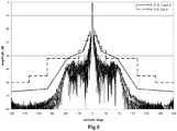
- Figures 7 and 8The significant improvement in measured F/B performance in a 0.6 meter reflector antenna configurations for both co-polar and cross-polar responses with a conventional prior art band clamp 1 and the "new" presently disclosed band clamp 1 configuration are illustrated in Figures 7 and 8 .
- Figures 9 and 10illustrate measured backlobe levels of co-polar and cross-polar radiation patterns in the 26 GHz band within the regulatory envelopes at greater than 71 dB with the Figure 4 band clamp 1 configuration, in which the width "A" is equal to 1.1 wavelengths.
- width "A”may be difficult to achieve for some operating frequencies without incorporating further structure in the radome and/or reflector dish periphery.
- the width "A”may be increased via the application of a fold 33 in the band clamp from the desired extent of the width "A” back toward the reflector dish 7.
- the pictured embodimentis simplified for demonstration purposes with respect to extending the width "A” but may similarly be applied with a fold 33 and proximal lip 17 that extends further inward and includes a turnback region 19 contacting the outer surface 21 of the signal area 23 of the reflector dish 7.
- an extension of the width "A"may be cost effectively achieved by attaching a further width ring 35 of metallic and/or metal coated material to the band clamp 1 outer diameter.
- the width ring 35may be applied with any desired width, cost effectively securely attached by spot welding or fasteners such as screws, rivets or the like.
- Figure 13illustrates 18 GHz band RF modeling software predictions of F/B improvement between a width ring 35 width "A" of 0.5 and 1.2 wavelengths.
- the width ring 35may be provided in an angled configuration as demonstrated in Figure 18 .
- RF modeling software predictions of F/B improvementindicate progressively increasing improvement as the angle applied increases from zero (flat width ring 35 cross section) to sixty degrees of diffraction gradient.
- the disclosed band clamp 1can enable significant manufacturing, delivery, installation and/or maintenance efficiencies. Because the band clamp 1 enables simplified radome 3 and reflector dish 7 periphery geometries, the resulting reflector antenna 13 may have improved materials and manufacturing costs. Because the band clamp 1 is simply and securely attached, installation and maintenance may be simplified compared to prior reflector antenna 13 configurations with complex peripheral geometries, delicate back lobe suppression ring coatings, platings and/or RF absorbing materials. Because the band clamp 1 may be compact and applied close to the reflector antenna aperture H, the overall diameter of the reflector antenna 13 may be reduced, which can reduce the reflector antenna 13 wind loading characteristics and the required packaging dimensions.
Landscapes
- Physics & Mathematics (AREA)
- Electromagnetism (AREA)
- Aerials With Secondary Devices (AREA)
- Details Of Aerials (AREA)
Description
- This invention relates to microwave reflector antennas. More particularly, the invention relates to a reflector antenna with a radome and reflector dish interconnection band clamp which enhances signal pattern and mechanical interconnection characteristics.
- The open end of a reflector antenna is typically enclosed by a radome coupled to the distal end of the reflector dish. The radome provides environmental protection and improves wind load characteristics of the antenna.
- Edges and/or channel paths of the reflector dish, radome and/or interconnection hardware, may diffract or enable spill-over of signal energy present in these areas, introducing undesirable backlobes into the reflector antenna signal pattern quantified as the front to back ratio (F/B) of the antenna. The F/B is regulated by international standards, and is specified by for example, the FCC in 47 CFR Ch.1 Part 101.115 in the United States, by ETSI in EN302217-4-1 and EN302217-4-12 in Europe, and by ACMA RALI FX 3
Appendix 11 in Australia. - Prior antenna signal pattern backlobe suppression techniques include adding a backlobe suppression ring to the radome, for example via metalizing of the radome periphery as disclosed in commonly owned
US Utility Patent No. 7,138,958 , titled "Reflector Antenna Radome with Backlobe Suppressor Ring and Method of Manufacturing" issued November 21, 2006 to Syed et al. However, the required metalizing operations may increase manufacturing complexity and/or cost, including elaborate coupling arrangements configured to securely retain the shroud upon the reflector dish without presenting undesired reflection edges, signal leakage paths and/or extending the overall size of the radome. Further, the thin metalized ring layer applied to the periphery of the radome may be fragile, requiring increased care to avoid damage during delivery and/or installation. - Reflectors employing castellated edge geometries to generate constructive interference of the edge diffraction components have also been shown to improve the F/B, for example as disclosed in commonly owned Canada Patent No.
CA887303 "Backlobe Reduction in Reflector-Type Antennas" by Holtum et al. Such arrangements increase the overall diameter of the antenna, which may complicate radome attachment, packaging and installation. - The addition of a shroud to a reflector antenna improves the signal pattern generally as a function of the shroud length, but also similarly introduces significant costs as the increasing length of the shroud also increases wind loading of the reflector antenna, requiring a corresponding increase in the antenna and antenna support structure strength. Further, an interconnection between the shroud and a radome may introduce significant F/B degradation.
- A
conventional band clamp 1 applied to retain aradome 3 upon thereflector dish 7 or shroud may introduce diffraction edges and/or signal leakage paths, for example as shown inFigure 1 . Metal taping, RF gaskets or the like may be applied to reduce F/B degradation resulting from band clamp use. However, these materials and procedures increase manufacturing costs and/or installation complexity and may be of limited long-term reliability. A reflector antenna with a radome, mounted by a band clamp, is for example disclosed inUS4581615 . Competition in the reflector antenna market has focused attention on improving electrical performance and minimization of overall manufacturing, inventory, distribution, installation and maintenance costs. Therefore, it is an object of the invention to provide a reflector antenna that overcomes deficiencies in the prior art. - The accompanying drawings, which are incorporated in and constitute a part of this specification, illustrate embodiments of the invention, where like reference numbers in the drawing figures refer to the same feature or element and may not be described in detail for every drawing figure in which they appear and, together with a general description of the invention given above, and the detailed description of the embodiments given below, serve to explain the principles of the invention.
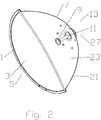
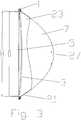
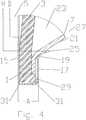
Figure 1 is a schematic enlarged cut-away side view of a conventional prior art band clamp radome and reflector dish interconnection, demonstrating an RF signal leakage path.Figure 2 is a schematic isometric cut-away view of a reflector antenna with radome to reflector dish band clamp interconnection.Figure 3 is a schematic partial cut-away side view of a radome to reflector dish band clamp interconnection.Figure 4 is an enlarged cut-away side view of a first exemplary radome to reflector dish band clamp interconnection.Figure 5 is a graph illustrating a range of exemplary band clamp distal lip inner diameter to reflector dish aperture ratios and their effect upon corresponding reflector antenna F/B over a range of operating frequencies.Figure 6 is a graph illustrating a range of band clamp widths and their effect upon corresponding reflector antenna F/B.Figure 7 is a graph comparing measured co-polar F/B performance related to RF signal leakage between conventional band clamp and presently disclosed "new" band clamp configurations.Figure 8 is a graph comparing measured cross-polar F/B performance related to RF signal leakage between conventional band clamp and presently disclosed "new" band clamp configurations.Figure 9 is a graph of measured co-polar radiation patterns of a 0.6m reflector antenna with a bandclamp with a 1.1 wavelength width.Figure 10 is a graph of measured cross-polar radiation patterns of a 0.6m reflector antenna with a bandclamp with a 1.1 wavelength width.Figure 11 is an enlarged cut-away side view of a second exemplary radome to reflector dish band clamp interconnection.Figure 12 is an enlarged cut-away side view of a third exemplary radome to reflector dish band clamp interconnection, including a width ring.Figure 13 is a graph comparing predicted F/B enhancement with a band clamp of width of 0.5 and 1.2 wavelengths.Figure 14 is a graph of measured co-polar radiation patterns for a reflector antenna with a band clamp with a 0.5 wavelength width.Figure 15 is a graph of measured cross-polar radiation patterns for a reflector antenna with a band clamp with a 0.5 wavelength width.Figure 16 is a graph of measured co-polar radiation patterns for a reflector antenna with a band clamp with a 1.2 wavelength width.Figure 17 is a graph of measured cross-polar radiation patterns for a reflector antenna with a band clamp with a 1.2 wavelength width.Figure 18 is an enlarged cut-away side view of a third exemplary radome to reflector dish band clamp interconnection, including a width ring with radial outward bend.Figure 19 is a graph comparing predicted F/B enhancement with a band clamp with a width ring configuration of between 0 and 60 degrees radial outward bend.- As shown in
Figures 2 and3 , aband clamp 1 is generally operative to retain aradome 3 upon the opendistal end 5 of areflector dish 7, creating an environmental seal that protects thereflector dish 7, subreflector 9 and/or feed 11 of areflector antenna 13 from environmental fouling. In a first exemplary embodiment, best shown inFigure 4 , theband clamp 1 is provided with inward facing distal andproximal lips turnback region 19 of theproximal lip 17 is dimensioned to engage theouter surface 21 of thesignal area 23 of thereflector dish 7. Theturnback region 19 may be applied, for example, as an outward bend prior to theinward end 25 of theproximal lip 17. - As the
band clamp 1 is tightened during interconnection of theradome 3 and thereflector dish 7, the diameter of theband clamp 1 is progressively reduced, driving theturnback region 19 against the convexouter surface 21 of thesignal area 23 of thereflector dish 7, into a uniform circumferential interference fit. As theband clamp 1 is further tightened, theturnback region 19 slides progressively inward along theouter surface 21 of thesignal area 23 of thereflector dish 7 toward the reflector dishproximal end 27. Thereby, thedistal lip 15 of theband clamp 1 also moves towards the reflector dishproximal end 27, securely clamping theradome 3 against thedistal end 5 of thereflector dish 7. Because the interference fit between theturnback region 19 and theouter surface 21 of thereflector dish 7 is circumferentially uniform, any RF leakage between these surfaces is reduced. - Although it is possible to apply extended flanges to the
reflector dish 7 and/orradome 3, these would increase the overall size of thereflector antenna 1, which may negatively impact wind loading, material requirements, inventory and transport packaging requirements. Therefore, flanges of a reduced size, dimensioned to provide secure mechanical interconnection, may be applied. Theradome 3 may be provided with a greater diameter than thereflector dish 7, anannular lip 29 of theradome 3 periphery mating with an outer diameter of thedistal end 5 of thereflector dish 7, keying theradome 3 coaxial with thereflector dish 7 and providing surface area for spacing theband clamp 1 from thesignal area 23 of thereflector dish 7. - The flanges may be dimensioned and the
band clamp 1 similarly dimensioned such that thedistal lip 15 of theband clamp 1 is even with or extends slightly inward of a reflector aperture H, defined as the largest diameter of thereflector dish 7 surface upon which signal energy is distributed by the subreflector 9, to form a band clamp inner diameter D. To minimize diffraction and/or scatter signal components at theband clamp 1distal lip 15, the band clamp inner diameter D may be dimensioned with respect to reflector aperture H, resulting in significant F/B enhancement as illustrated inFigure 5 . For reduced F/B in areflector antenna 13 of minimal overall diameter, a D/H ratio of 0.97-1.0 may be applied. - Referring again to
Figure 4 , another dimension of theband clamp 1 impacting the F/B is theband clamp 1 width "A" which determines the distance betweenband clamp 1 outer corner(s) 31 acting as diffraction/scatter surfaces. As shown inFigure 6 , normalized F/B is improved when the width "A" is between 0.8 and 1.5 wavelengths of the operating frequency, which can be operative to generate mutual interference of surface currents traveling along theband clamp 1 outer periphery and/or scatter interference. - The significant improvement in measured F/B performance in a 0.6 meter reflector antenna configurations for both co-polar and cross-polar responses with a conventional prior
art band clamp 1 and the "new" presently disclosedband clamp 1 configuration are illustrated inFigures 7 and8 .Figures 9 and10 illustrate measured backlobe levels of co-polar and cross-polar radiation patterns in the 26 GHz band within the regulatory envelopes at greater than 71 dB with theFigure 4 band clamp 1 configuration, in which the width "A" is equal to 1.1 wavelengths. - One skilled in the art will appreciate that the optimal range of widths "A" may be difficult to achieve for some operating frequencies without incorporating further structure in the radome and/or reflector dish periphery. In a second embodiment, for example as shown in
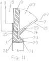
Figure 11 , the width "A" may be increased via the application of afold 33 in the band clamp from the desired extent of the width "A" back toward thereflector dish 7. The pictured embodiment is simplified for demonstration purposes with respect to extending the width "A" but may similarly be applied with afold 33 andproximal lip 17 that extends further inward and includes aturnback region 19 contacting theouter surface 21 of thesignal area 23 of thereflector dish 7. - In a third embodiment, for example as shown in
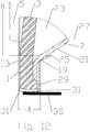
Figure 12 , an extension of the width "A" may be cost effectively achieved by attaching afurther width ring 35 of metallic and/or metal coated material to theband clamp 1 outer diameter. Thewidth ring 35 may be applied with any desired width, cost effectively securely attached by spot welding or fasteners such as screws, rivets or the like. Figure 13 illustrates 18 GHz band RF modeling software predictions of F/B improvement between awidth ring 35 width "A" of 0.5 and 1.2 wavelengths. Measured co-polar and cross-polar F/B performance of aFigure 12 band clamp 1 withwidth ring 35 of width "A" = 0.5 wavelengths is shown inFigures 14 and15 . Note the performance meets the regulatory envelope across the entire range, but with no margin. However, as shown inFigures 16 and17 , the measured co-polar and cross-polar F/B performance of aFigure 12 band clamp 1 withwidth ring 35 of width "A" = 1.2 wavelengths is significantly improved and well within the regulatory envelope throughout the entire range.- In a fourth embodiment, the
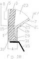
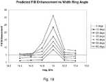
width ring 35 may be provided in an angled configuration as demonstrated inFigure 18 . As shown inFigure 19 , RF modeling software predictions of F/B improvement indicate progressively increasing improvement as the angle applied increases from zero (flat width ring 35 cross section) to sixty degrees of diffraction gradient. - One skilled in the art will appreciate that in addition to improving the electrical performance of the
reflector antenna 13, the disclosedband clamp 1 can enable significant manufacturing, delivery, installation and/or maintenance efficiencies. Because theband clamp 1 enables simplifiedradome 3 andreflector dish 7 periphery geometries, the resultingreflector antenna 13 may have improved materials and manufacturing costs. Because theband clamp 1 is simply and securely attached, installation and maintenance may be simplified compared toprior reflector antenna 13 configurations with complex peripheral geometries, delicate back lobe suppression ring coatings, platings and/or RF absorbing materials. Because theband clamp 1 may be compact and applied close to the reflector antenna aperture H, the overall diameter of thereflector antenna 13 may be reduced, which can reduce thereflector antenna 13 wind loading characteristics and the required packaging dimensions.Table of Parts 1 band clamp 3 radome 5 distal end 7 reflector dish 9 subreflector 11 feed 13 reflector antenna 15 distal lip 17 proximal lip 19 turnback region 21 outer surface 23 signal area 25 inward end 27 proximal end 29 annular lip 31 outer corner 33 fold 35 width ring - Where in the foregoing description reference has been made to materials, ratios, integers or components having known equivalents then such equivalents are herein incorporated as if individually set forth.
- While the present invention has been illustrated by the description of the embodiments thereof, and while the embodiments have been described in considerable detail, it is not the intention of the applicant to restrict or in any way limit the scope of the appended claims to such detail. Additional advantages and modifications will readily appear to those skilled in the art. Therefore, the invention in its broader aspects is not limited to the specific details, representative apparatus, methods, and illustrative examples shown and described.
Claims (8)
- A reflector antenna (13), comprising:a reflector dish (7);a radome (3);a band clamp (1) coupling the radome (3) to a distal end (5) of the reflector dish (7);the band clamp (1) provided with an inward projecting proximal lip (17) and an inward projecting distal lip (15);characterized in thatthe distal lip (15) is dimensioned with an inner diameter less than or equal to a reflector aperture of the reflector dish (7);in thatthe proximal lip (17) is provided with a turnback region (19) dimensioned to engage an outer surface of a signal area of the reflector dish (7) in an interference fit; andin that the band clamp (1) has a width between 0.8 and 1.5 wavelengths of an operating frequency.
- The reflector antenna of claim 1, wherein a ratio of the inner diameter and the reflector aperture is equal to or between 0.97 and 1.
- The reflector antenna of claim 1, wherein the proximal lip (17) includes a fold (33) towards the reflector dish (7).
- The reflector antenna of claim 1, wherein the turnback region (19) is an outward bend of the proximal lip (17), prior to an inward end (25) of the proximal lip (17).
- The reflector antenna of claim 1, wherein a width ring (35) is coupled to an outer diameter of the band clamp (1).
- The reflector antenna of claim 5, wherein the width ring (35) has an angle.
- The reflector antenna of claim 6, wherein the angle is 60 degrees.
- A method for reducing a front to back ratio of a reflector antenna (13) with a reflector dish (7) and a radome (3), comprising the steps of:forming a band clamp (1) with an inward projecting proximal lip (17) and an inward projecting distal lip (15); andcoupling the radome (3) to the reflector dish (7) with the band clamp (1);characterized in thatthe distal lip (15) is dimensioned with an inner diameter less than or equal to a reflector aperture of the reflector dish 7;in thatthe proximal lip (17) is provided with a turnback region (19) dimensioned to engage an outer surface of a signal area of the reflector dish (7) in an interference fit; andin that
the band clamp (1) has a width between 0.8 and 1.5 wavelengths of an operating frequency.
Applications Claiming Priority (2)
| Application Number | Priority Date | Filing Date | Title |
|---|---|---|---|
| US12/636,068US8259028B2 (en) | 2009-12-11 | 2009-12-11 | Reflector antenna radome attachment band clamp |
| PCT/IB2010/054173WO2011070451A2 (en) | 2009-12-11 | 2010-09-15 | Reflector antenna radome attachment band clamp |
Publications (3)
| Publication Number | Publication Date |
|---|---|
| EP2510576A2 EP2510576A2 (en) | 2012-10-17 |
| EP2510576A4 EP2510576A4 (en) | 2014-05-14 |
| EP2510576B1true EP2510576B1 (en) | 2017-12-13 |
Family
ID=44142338
Family Applications (1)
| Application Number | Title | Priority Date | Filing Date |
|---|---|---|---|
| EP10835569.4ANot-in-forceEP2510576B1 (en) | 2009-12-11 | 2010-09-15 | Reflector antenna radome attachment band clamp |
Country Status (5)
| Country | Link |
|---|---|
| US (1) | US8259028B2 (en) |
| EP (1) | EP2510576B1 (en) |
| CN (1) | CN102714343B (en) |
| BR (1) | BR112012013654B1 (en) |
| WO (1) | WO2011070451A2 (en) |
Families Citing this family (160)
| Publication number | Priority date | Publication date | Assignee | Title |
|---|---|---|---|---|
| US9083083B2 (en)* | 2009-12-11 | 2015-07-14 | Commscope Technologies Llc | Radome attachment band clamp |
| US8581795B2 (en) | 2011-09-01 | 2013-11-12 | Andrew Llc | Low sidelobe reflector antenna |
| US9019164B2 (en) | 2011-09-12 | 2015-04-28 | Andrew Llc | Low sidelobe reflector antenna with shield |
| US9050692B2 (en)* | 2011-10-24 | 2015-06-09 | Commscope Technologies Llc | Method and apparatus for radome and reflector dish interconnection |
| WO2014035493A1 (en) | 2012-08-31 | 2014-03-06 | Andrew Llc | Radome attachment band clamp |
| EP2712019B1 (en) | 2012-09-24 | 2017-11-22 | Alcatel- Lucent Shanghai Bell Co., Ltd | Device for attaching a radome to a parabolic reflector of an antenna |
| US9113347B2 (en) | 2012-12-05 | 2015-08-18 | At&T Intellectual Property I, Lp | Backhaul link for distributed antenna system |
| EP2772985B1 (en)* | 2013-02-27 | 2018-08-08 | Alcatel-Lucent Shanghai Bell Co., Ltd | System for attaching a planar radome to the concave reflector of an antenna |
| US9999038B2 (en) | 2013-05-31 | 2018-06-12 | At&T Intellectual Property I, L.P. | Remote distributed antenna system |
| US9525524B2 (en) | 2013-05-31 | 2016-12-20 | At&T Intellectual Property I, L.P. | Remote distributed antenna system |
| USD741843S1 (en)* | 2013-06-05 | 2015-10-27 | Google Inc. | Terrestrial unit for connectivity to a balloon network |
| USD744986S1 (en)* | 2013-09-06 | 2015-12-08 | Ubiquiti Networks, Inc. | Wireless transmission station |
| US9985347B2 (en) | 2013-10-30 | 2018-05-29 | Commscope Technologies Llc | Broad band radome for microwave antenna |
| US9583822B2 (en)* | 2013-10-30 | 2017-02-28 | Commscope Technologies Llc | Broad band radome for microwave antenna |
| US8897697B1 (en) | 2013-11-06 | 2014-11-25 | At&T Intellectual Property I, Lp | Millimeter-wave surface-wave communications |
| USD803817S1 (en) | 2014-01-31 | 2017-11-28 | Ubiquiti Networks, Inc. | Duplex, point-to-point wireless radio antenna system |
| US9577323B2 (en) | 2014-03-07 | 2017-02-21 | Commscope Technologies Llc | Radome—reflector assembly mechanism |
| US9768833B2 (en) | 2014-09-15 | 2017-09-19 | At&T Intellectual Property I, L.P. | Method and apparatus for sensing a condition in a transmission medium of electromagnetic waves |
| US10063280B2 (en) | 2014-09-17 | 2018-08-28 | At&T Intellectual Property I, L.P. | Monitoring and mitigating conditions in a communication network |
| US9615269B2 (en) | 2014-10-02 | 2017-04-04 | At&T Intellectual Property I, L.P. | Method and apparatus that provides fault tolerance in a communication network |
| US9685992B2 (en) | 2014-10-03 | 2017-06-20 | At&T Intellectual Property I, L.P. | Circuit panel network and methods thereof |
| US9503189B2 (en) | 2014-10-10 | 2016-11-22 | At&T Intellectual Property I, L.P. | Method and apparatus for arranging communication sessions in a communication system |
| US9973299B2 (en) | 2014-10-14 | 2018-05-15 | At&T Intellectual Property I, L.P. | Method and apparatus for adjusting a mode of communication in a communication network |
| US9762289B2 (en) | 2014-10-14 | 2017-09-12 | At&T Intellectual Property I, L.P. | Method and apparatus for transmitting or receiving signals in a transportation system |
| US9520945B2 (en) | 2014-10-21 | 2016-12-13 | At&T Intellectual Property I, L.P. | Apparatus for providing communication services and methods thereof |
| US9627768B2 (en) | 2014-10-21 | 2017-04-18 | At&T Intellectual Property I, L.P. | Guided-wave transmission device with non-fundamental mode propagation and methods for use therewith |
| US9312919B1 (en) | 2014-10-21 | 2016-04-12 | At&T Intellectual Property I, Lp | Transmission device with impairment compensation and methods for use therewith |
| US9780834B2 (en) | 2014-10-21 | 2017-10-03 | At&T Intellectual Property I, L.P. | Method and apparatus for transmitting electromagnetic waves |
| US9769020B2 (en) | 2014-10-21 | 2017-09-19 | At&T Intellectual Property I, L.P. | Method and apparatus for responding to events affecting communications in a communication network |
| US9653770B2 (en) | 2014-10-21 | 2017-05-16 | At&T Intellectual Property I, L.P. | Guided wave coupler, coupling module and methods for use therewith |
| US9577306B2 (en) | 2014-10-21 | 2017-02-21 | At&T Intellectual Property I, L.P. | Guided-wave transmission device and methods for use therewith |
| US20170338568A1 (en)* | 2014-11-03 | 2017-11-23 | Commscope Technologies Llc | Circumferencial frame for antenna back-lobe and side-lobe attentuation |
| US9954287B2 (en) | 2014-11-20 | 2018-04-24 | At&T Intellectual Property I, L.P. | Apparatus for converting wireless signals and electromagnetic waves and methods thereof |
| US10340573B2 (en) | 2016-10-26 | 2019-07-02 | At&T Intellectual Property I, L.P. | Launcher with cylindrical coupling device and methods for use therewith |
| US9461706B1 (en) | 2015-07-31 | 2016-10-04 | At&T Intellectual Property I, Lp | Method and apparatus for exchanging communication signals |
| US9742462B2 (en) | 2014-12-04 | 2017-08-22 | At&T Intellectual Property I, L.P. | Transmission medium and communication interfaces and methods for use therewith |
| US10009067B2 (en) | 2014-12-04 | 2018-06-26 | At&T Intellectual Property I, L.P. | Method and apparatus for configuring a communication interface |
| US9800327B2 (en) | 2014-11-20 | 2017-10-24 | At&T Intellectual Property I, L.P. | Apparatus for controlling operations of a communication device and methods thereof |
| US9997819B2 (en) | 2015-06-09 | 2018-06-12 | At&T Intellectual Property I, L.P. | Transmission medium and method for facilitating propagation of electromagnetic waves via a core |
| US9544006B2 (en) | 2014-11-20 | 2017-01-10 | At&T Intellectual Property I, L.P. | Transmission device with mode division multiplexing and methods for use therewith |
| US10243784B2 (en) | 2014-11-20 | 2019-03-26 | At&T Intellectual Property I, L.P. | System for generating topology information and methods thereof |
| US10144036B2 (en) | 2015-01-30 | 2018-12-04 | At&T Intellectual Property I, L.P. | Method and apparatus for mitigating interference affecting a propagation of electromagnetic waves guided by a transmission medium |
| US9876570B2 (en) | 2015-02-20 | 2018-01-23 | At&T Intellectual Property I, Lp | Guided-wave transmission device with non-fundamental mode propagation and methods for use therewith |
| US9749013B2 (en) | 2015-03-17 | 2017-08-29 | At&T Intellectual Property I, L.P. | Method and apparatus for reducing attenuation of electromagnetic waves guided by a transmission medium |
| US9705561B2 (en) | 2015-04-24 | 2017-07-11 | At&T Intellectual Property I, L.P. | Directional coupling device and methods for use therewith |
| US10224981B2 (en) | 2015-04-24 | 2019-03-05 | At&T Intellectual Property I, Lp | Passive electrical coupling device and methods for use therewith |
| US9948354B2 (en) | 2015-04-28 | 2018-04-17 | At&T Intellectual Property I, L.P. | Magnetic coupling device with reflective plate and methods for use therewith |
| US9793954B2 (en) | 2015-04-28 | 2017-10-17 | At&T Intellectual Property I, L.P. | Magnetic coupling device and methods for use therewith |
| US9490869B1 (en) | 2015-05-14 | 2016-11-08 | At&T Intellectual Property I, L.P. | Transmission medium having multiple cores and methods for use therewith |
| US9871282B2 (en) | 2015-05-14 | 2018-01-16 | At&T Intellectual Property I, L.P. | At least one transmission medium having a dielectric surface that is covered at least in part by a second dielectric |
| US9748626B2 (en) | 2015-05-14 | 2017-08-29 | At&T Intellectual Property I, L.P. | Plurality of cables having different cross-sectional shapes which are bundled together to form a transmission medium |
| US10650940B2 (en) | 2015-05-15 | 2020-05-12 | At&T Intellectual Property I, L.P. | Transmission medium having a conductive material and methods for use therewith |
| EP3298655A4 (en)* | 2015-05-21 | 2019-01-16 | Commscope Technologies LLC | Segmented antenna radome |
| US9917341B2 (en) | 2015-05-27 | 2018-03-13 | At&T Intellectual Property I, L.P. | Apparatus and method for launching electromagnetic waves and for modifying radial dimensions of the propagating electromagnetic waves |
| US9912381B2 (en) | 2015-06-03 | 2018-03-06 | At&T Intellectual Property I, Lp | Network termination and methods for use therewith |
| US9866309B2 (en) | 2015-06-03 | 2018-01-09 | At&T Intellectual Property I, Lp | Host node device and methods for use therewith |
| US10103801B2 (en) | 2015-06-03 | 2018-10-16 | At&T Intellectual Property I, L.P. | Host node device and methods for use therewith |
| US10812174B2 (en) | 2015-06-03 | 2020-10-20 | At&T Intellectual Property I, L.P. | Client node device and methods for use therewith |
| US9913139B2 (en) | 2015-06-09 | 2018-03-06 | At&T Intellectual Property I, L.P. | Signal fingerprinting for authentication of communicating devices |
| US9608692B2 (en) | 2015-06-11 | 2017-03-28 | At&T Intellectual Property I, L.P. | Repeater and methods for use therewith |
| US9820146B2 (en) | 2015-06-12 | 2017-11-14 | At&T Intellectual Property I, L.P. | Method and apparatus for authentication and identity management of communicating devices |
| US9667317B2 (en) | 2015-06-15 | 2017-05-30 | At&T Intellectual Property I, L.P. | Method and apparatus for providing security using network traffic adjustments |
| US9509415B1 (en) | 2015-06-25 | 2016-11-29 | At&T Intellectual Property I, L.P. | Methods and apparatus for inducing a fundamental wave mode on a transmission medium |
| US9640850B2 (en) | 2015-06-25 | 2017-05-02 | At&T Intellectual Property I, L.P. | Methods and apparatus for inducing a non-fundamental wave mode on a transmission medium |
| US9865911B2 (en) | 2015-06-25 | 2018-01-09 | At&T Intellectual Property I, L.P. | Waveguide system for slot radiating first electromagnetic waves that are combined into a non-fundamental wave mode second electromagnetic wave on a transmission medium |
| US10320586B2 (en) | 2015-07-14 | 2019-06-11 | At&T Intellectual Property I, L.P. | Apparatus and methods for generating non-interfering electromagnetic waves on an insulated transmission medium |
| US10341142B2 (en) | 2015-07-14 | 2019-07-02 | At&T Intellectual Property I, L.P. | Apparatus and methods for generating non-interfering electromagnetic waves on an uninsulated conductor |
| US9882257B2 (en) | 2015-07-14 | 2018-01-30 | At&T Intellectual Property I, L.P. | Method and apparatus for launching a wave mode that mitigates interference |
| US10033108B2 (en) | 2015-07-14 | 2018-07-24 | At&T Intellectual Property I, L.P. | Apparatus and methods for generating an electromagnetic wave having a wave mode that mitigates interference |
| US9628116B2 (en) | 2015-07-14 | 2017-04-18 | At&T Intellectual Property I, L.P. | Apparatus and methods for transmitting wireless signals |
| US10205655B2 (en) | 2015-07-14 | 2019-02-12 | At&T Intellectual Property I, L.P. | Apparatus and methods for communicating utilizing an antenna array and multiple communication paths |
| US9853342B2 (en) | 2015-07-14 | 2017-12-26 | At&T Intellectual Property I, L.P. | Dielectric transmission medium connector and methods for use therewith |
| US10044409B2 (en) | 2015-07-14 | 2018-08-07 | At&T Intellectual Property I, L.P. | Transmission medium and methods for use therewith |
| US10170840B2 (en) | 2015-07-14 | 2019-01-01 | At&T Intellectual Property I, L.P. | Apparatus and methods for sending or receiving electromagnetic signals |
| US9722318B2 (en) | 2015-07-14 | 2017-08-01 | At&T Intellectual Property I, L.P. | Method and apparatus for coupling an antenna to a device |
| US9847566B2 (en) | 2015-07-14 | 2017-12-19 | At&T Intellectual Property I, L.P. | Method and apparatus for adjusting a field of a signal to mitigate interference |
| US10148016B2 (en) | 2015-07-14 | 2018-12-04 | At&T Intellectual Property I, L.P. | Apparatus and methods for communicating utilizing an antenna array |
| US9608740B2 (en) | 2015-07-15 | 2017-03-28 | At&T Intellectual Property I, L.P. | Method and apparatus for launching a wave mode that mitigates interference |
| US10090606B2 (en) | 2015-07-15 | 2018-10-02 | At&T Intellectual Property I, L.P. | Antenna system with dielectric array and methods for use therewith |
| US9793951B2 (en) | 2015-07-15 | 2017-10-17 | At&T Intellectual Property I, L.P. | Method and apparatus for launching a wave mode that mitigates interference |
| US9749053B2 (en) | 2015-07-23 | 2017-08-29 | At&T Intellectual Property I, L.P. | Node device, repeater and methods for use therewith |
| US9948333B2 (en) | 2015-07-23 | 2018-04-17 | At&T Intellectual Property I, L.P. | Method and apparatus for wireless communications to mitigate interference |
| US9871283B2 (en) | 2015-07-23 | 2018-01-16 | At&T Intellectual Property I, Lp | Transmission medium having a dielectric core comprised of plural members connected by a ball and socket configuration |
| US9912027B2 (en) | 2015-07-23 | 2018-03-06 | At&T Intellectual Property I, L.P. | Method and apparatus for exchanging communication signals |
| US9967173B2 (en) | 2015-07-31 | 2018-05-08 | At&T Intellectual Property I, L.P. | Method and apparatus for authentication and identity management of communicating devices |
| US9735833B2 (en) | 2015-07-31 | 2017-08-15 | At&T Intellectual Property I, L.P. | Method and apparatus for communications management in a neighborhood network |
| USD816645S1 (en)* | 2015-08-24 | 2018-05-01 | Ubiquiti Networks, Inc. | Shrouded microwave antenna reflector |
| US10009063B2 (en) | 2015-09-16 | 2018-06-26 | At&T Intellectual Property I, L.P. | Method and apparatus for use with a radio distributed antenna system having an out-of-band reference signal |
| US10136434B2 (en) | 2015-09-16 | 2018-11-20 | At&T Intellectual Property I, L.P. | Method and apparatus for use with a radio distributed antenna system having an ultra-wideband control channel |
| US10079661B2 (en) | 2015-09-16 | 2018-09-18 | At&T Intellectual Property I, L.P. | Method and apparatus for use with a radio distributed antenna system having a clock reference |
| US9769128B2 (en) | 2015-09-28 | 2017-09-19 | At&T Intellectual Property I, L.P. | Method and apparatus for encryption of communications over a network |
| US9729197B2 (en) | 2015-10-01 | 2017-08-08 | At&T Intellectual Property I, L.P. | Method and apparatus for communicating network management traffic over a network |
| US9876264B2 (en) | 2015-10-02 | 2018-01-23 | At&T Intellectual Property I, Lp | Communication system, guided wave switch and methods for use therewith |
| US10355367B2 (en) | 2015-10-16 | 2019-07-16 | At&T Intellectual Property I, L.P. | Antenna structure for exchanging wireless signals |
| US9912419B1 (en) | 2016-08-24 | 2018-03-06 | At&T Intellectual Property I, L.P. | Method and apparatus for managing a fault in a distributed antenna system |
| US9860075B1 (en) | 2016-08-26 | 2018-01-02 | At&T Intellectual Property I, L.P. | Method and communication node for broadband distribution |
| US10291311B2 (en) | 2016-09-09 | 2019-05-14 | At&T Intellectual Property I, L.P. | Method and apparatus for mitigating a fault in a distributed antenna system |
| US11032819B2 (en) | 2016-09-15 | 2021-06-08 | At&T Intellectual Property I, L.P. | Method and apparatus for use with a radio distributed antenna system having a control channel reference signal |
| EP3516735A4 (en)* | 2016-09-23 | 2020-04-22 | Commscope Technologies LLC | Antenna cover and methods of retention |
| US10135146B2 (en) | 2016-10-18 | 2018-11-20 | At&T Intellectual Property I, L.P. | Apparatus and methods for launching guided waves via circuits |
| US10135147B2 (en) | 2016-10-18 | 2018-11-20 | At&T Intellectual Property I, L.P. | Apparatus and methods for launching guided waves via an antenna |
| US10340600B2 (en) | 2016-10-18 | 2019-07-02 | At&T Intellectual Property I, L.P. | Apparatus and methods for launching guided waves via plural waveguide systems |
| US10811767B2 (en) | 2016-10-21 | 2020-10-20 | At&T Intellectual Property I, L.P. | System and dielectric antenna with convex dielectric radome |
| US10374316B2 (en) | 2016-10-21 | 2019-08-06 | At&T Intellectual Property I, L.P. | System and dielectric antenna with non-uniform dielectric |
| US9991580B2 (en) | 2016-10-21 | 2018-06-05 | At&T Intellectual Property I, L.P. | Launcher and coupling system for guided wave mode cancellation |
| US9876605B1 (en) | 2016-10-21 | 2018-01-23 | At&T Intellectual Property I, L.P. | Launcher and coupling system to support desired guided wave mode |
| US10312567B2 (en) | 2016-10-26 | 2019-06-04 | At&T Intellectual Property I, L.P. | Launcher with planar strip antenna and methods for use therewith |
| US10498044B2 (en) | 2016-11-03 | 2019-12-03 | At&T Intellectual Property I, L.P. | Apparatus for configuring a surface of an antenna |
| US10291334B2 (en) | 2016-11-03 | 2019-05-14 | At&T Intellectual Property I, L.P. | System for detecting a fault in a communication system |
| US10225025B2 (en) | 2016-11-03 | 2019-03-05 | At&T Intellectual Property I, L.P. | Method and apparatus for detecting a fault in a communication system |
| US10224634B2 (en) | 2016-11-03 | 2019-03-05 | At&T Intellectual Property I, L.P. | Methods and apparatus for adjusting an operational characteristic of an antenna |
| US10535928B2 (en) | 2016-11-23 | 2020-01-14 | At&T Intellectual Property I, L.P. | Antenna system and methods for use therewith |
| US10340603B2 (en) | 2016-11-23 | 2019-07-02 | At&T Intellectual Property I, L.P. | Antenna system having shielded structural configurations for assembly |
| US10340601B2 (en) | 2016-11-23 | 2019-07-02 | At&T Intellectual Property I, L.P. | Multi-antenna system and methods for use therewith |
| US10178445B2 (en) | 2016-11-23 | 2019-01-08 | At&T Intellectual Property I, L.P. | Methods, devices, and systems for load balancing between a plurality of waveguides |
| US10090594B2 (en) | 2016-11-23 | 2018-10-02 | At&T Intellectual Property I, L.P. | Antenna system having structural configurations for assembly |
| US10361489B2 (en) | 2016-12-01 | 2019-07-23 | At&T Intellectual Property I, L.P. | Dielectric dish antenna system and methods for use therewith |
| US10305190B2 (en) | 2016-12-01 | 2019-05-28 | At&T Intellectual Property I, L.P. | Reflecting dielectric antenna system and methods for use therewith |
| US10637149B2 (en) | 2016-12-06 | 2020-04-28 | At&T Intellectual Property I, L.P. | Injection molded dielectric antenna and methods for use therewith |
| US10020844B2 (en) | 2016-12-06 | 2018-07-10 | T&T Intellectual Property I, L.P. | Method and apparatus for broadcast communication via guided waves |
| US10727599B2 (en) | 2016-12-06 | 2020-07-28 | At&T Intellectual Property I, L.P. | Launcher with slot antenna and methods for use therewith |
| US10819035B2 (en) | 2016-12-06 | 2020-10-27 | At&T Intellectual Property I, L.P. | Launcher with helical antenna and methods for use therewith |
| US10694379B2 (en) | 2016-12-06 | 2020-06-23 | At&T Intellectual Property I, L.P. | Waveguide system with device-based authentication and methods for use therewith |
| US10439675B2 (en) | 2016-12-06 | 2019-10-08 | At&T Intellectual Property I, L.P. | Method and apparatus for repeating guided wave communication signals |
| US10135145B2 (en) | 2016-12-06 | 2018-11-20 | At&T Intellectual Property I, L.P. | Apparatus and methods for generating an electromagnetic wave along a transmission medium |
| US10326494B2 (en) | 2016-12-06 | 2019-06-18 | At&T Intellectual Property I, L.P. | Apparatus for measurement de-embedding and methods for use therewith |
| US10755542B2 (en) | 2016-12-06 | 2020-08-25 | At&T Intellectual Property I, L.P. | Method and apparatus for surveillance via guided wave communication |
| US9927517B1 (en) | 2016-12-06 | 2018-03-27 | At&T Intellectual Property I, L.P. | Apparatus and methods for sensing rainfall |
| US10382976B2 (en) | 2016-12-06 | 2019-08-13 | At&T Intellectual Property I, L.P. | Method and apparatus for managing wireless communications based on communication paths and network device positions |
| US10446936B2 (en) | 2016-12-07 | 2019-10-15 | At&T Intellectual Property I, L.P. | Multi-feed dielectric antenna system and methods for use therewith |
| US10389029B2 (en) | 2016-12-07 | 2019-08-20 | At&T Intellectual Property I, L.P. | Multi-feed dielectric antenna system with core selection and methods for use therewith |
| US9893795B1 (en) | 2016-12-07 | 2018-02-13 | At&T Intellectual Property I, Lp | Method and repeater for broadband distribution |
| US10168695B2 (en) | 2016-12-07 | 2019-01-01 | At&T Intellectual Property I, L.P. | Method and apparatus for controlling an unmanned aircraft |
| US10359749B2 (en) | 2016-12-07 | 2019-07-23 | At&T Intellectual Property I, L.P. | Method and apparatus for utilities management via guided wave communication |
| US10139820B2 (en) | 2016-12-07 | 2018-11-27 | At&T Intellectual Property I, L.P. | Method and apparatus for deploying equipment of a communication system |
| US10027397B2 (en) | 2016-12-07 | 2018-07-17 | At&T Intellectual Property I, L.P. | Distributed antenna system and methods for use therewith |
| US10547348B2 (en) | 2016-12-07 | 2020-01-28 | At&T Intellectual Property I, L.P. | Method and apparatus for switching transmission mediums in a communication system |
| US10243270B2 (en) | 2016-12-07 | 2019-03-26 | At&T Intellectual Property I, L.P. | Beam adaptive multi-feed dielectric antenna system and methods for use therewith |
| US9998870B1 (en) | 2016-12-08 | 2018-06-12 | At&T Intellectual Property I, L.P. | Method and apparatus for proximity sensing |
| US10530505B2 (en) | 2016-12-08 | 2020-01-07 | At&T Intellectual Property I, L.P. | Apparatus and methods for launching electromagnetic waves along a transmission medium |
| US10389037B2 (en) | 2016-12-08 | 2019-08-20 | At&T Intellectual Property I, L.P. | Apparatus and methods for selecting sections of an antenna array and use therewith |
| US9911020B1 (en) | 2016-12-08 | 2018-03-06 | At&T Intellectual Property I, L.P. | Method and apparatus for tracking via a radio frequency identification device |
| US10069535B2 (en) | 2016-12-08 | 2018-09-04 | At&T Intellectual Property I, L.P. | Apparatus and methods for launching electromagnetic waves having a certain electric field structure |
| US10777873B2 (en) | 2016-12-08 | 2020-09-15 | At&T Intellectual Property I, L.P. | Method and apparatus for mounting network devices |
| US10916969B2 (en) | 2016-12-08 | 2021-02-09 | At&T Intellectual Property I, L.P. | Method and apparatus for providing power using an inductive coupling |
| US10601494B2 (en) | 2016-12-08 | 2020-03-24 | At&T Intellectual Property I, L.P. | Dual-band communication device and method for use therewith |
| US10103422B2 (en) | 2016-12-08 | 2018-10-16 | At&T Intellectual Property I, L.P. | Method and apparatus for mounting network devices |
| US10326689B2 (en) | 2016-12-08 | 2019-06-18 | At&T Intellectual Property I, L.P. | Method and system for providing alternative communication paths |
| US10938108B2 (en) | 2016-12-08 | 2021-03-02 | At&T Intellectual Property I, L.P. | Frequency selective multi-feed dielectric antenna system and methods for use therewith |
| US10411356B2 (en) | 2016-12-08 | 2019-09-10 | At&T Intellectual Property I, L.P. | Apparatus and methods for selectively targeting communication devices with an antenna array |
| US9838896B1 (en) | 2016-12-09 | 2017-12-05 | At&T Intellectual Property I, L.P. | Method and apparatus for assessing network coverage |
| US10264586B2 (en) | 2016-12-09 | 2019-04-16 | At&T Mobility Ii Llc | Cloud-based packet controller and methods for use therewith |
| US10340983B2 (en) | 2016-12-09 | 2019-07-02 | At&T Intellectual Property I, L.P. | Method and apparatus for surveying remote sites via guided wave communications |
| US9973940B1 (en) | 2017-02-27 | 2018-05-15 | At&T Intellectual Property I, L.P. | Apparatus and methods for dynamic impedance matching of a guided wave launcher |
| US10298293B2 (en) | 2017-03-13 | 2019-05-21 | At&T Intellectual Property I, L.P. | Apparatus of communication utilizing wireless network devices |
| CN107528129B (en)* | 2017-07-12 | 2020-01-03 | 广东通宇通讯股份有限公司 | Microwave antenna |
| EP3673537A4 (en) | 2017-08-22 | 2021-05-19 | CommScope Technologies LLC | PARABOLIC MIRRORS THAT SUPPORT WEAK SECONDARY LOBE RADIATION DIAGRAMS |
| US11367964B2 (en)* | 2018-01-02 | 2022-06-21 | Optisys, LLC | Dual-band integrated printed antenna feed |
| US11594822B2 (en) | 2020-02-19 | 2023-02-28 | Commscope Technologies Llc | Parabolic reflector antennas with improved cylindrically-shaped shields |
| CN113889739B (en)* | 2021-09-06 | 2022-05-17 | 哈尔滨工业大学 | An antenna protective cover supporting and clamping device |
Family Cites Families (22)
| Publication number | Priority date | Publication date | Assignee | Title |
|---|---|---|---|---|
| US2413187A (en) | 1942-03-06 | 1946-12-24 | Westinghouse Electric Corp | Device for radiation of radio waves |
| US2647212A (en)* | 1946-01-17 | 1953-07-28 | Bell Telephone Labor Inc | Antenna system |
| GB966398A (en)* | 1962-02-09 | 1964-08-12 | Marconi Co Ltd | Improvements in or relating to radio reflectors |
| US3140491A (en) | 1963-01-24 | 1964-07-07 | Boeing Co | Diffraction shield consisting of notched ring which frames passive reflector |
| US4410892A (en) | 1981-05-26 | 1983-10-18 | Andrew Corporation | Reflector-type microwave antennas with absorber lined conical feed |
| EP0084420A3 (en)* | 1982-01-19 | 1983-08-03 | P.A. Consulting Services Limited | An antenna, particularly for the reception of satellite communications |
| US4581615A (en) | 1983-02-08 | 1986-04-08 | Levy Stanley P | Double reflector antenna with integral radome reflector support |
| US4920350A (en) | 1984-02-17 | 1990-04-24 | Comsat Telesystems, Inc. | Satellite tracking antenna system |
| CA1247234A (en) | 1984-02-17 | 1988-12-20 | William H. Mcguire | Satellite tracking antenna system with a two-degree freedom gimballed mount |
| US4876554A (en) | 1988-01-19 | 1989-10-24 | Qualcomm, Inc. | Pillbox antenna and antenna assembly |
| US5298911A (en) | 1990-09-18 | 1994-03-29 | Li Ming Chang | Serrated-roll edge for microwave antennas |
| DE4436596C2 (en)* | 1994-10-13 | 1998-04-09 | Bosch Gmbh Robert | Aperture cover for a microwave antenna |
| US6137449A (en) | 1996-09-26 | 2000-10-24 | Kildal; Per-Simon | Reflector antenna with a self-supported feed |
| DE69834968T2 (en)* | 1997-02-14 | 2006-11-16 | Andrew Ag, Bachenbulach | Dual reflector microwave antenna |
| US6522305B2 (en) | 2000-02-25 | 2003-02-18 | Andrew Corporation | Microwave antennas |
| US6184840B1 (en)* | 2000-03-01 | 2001-02-06 | Smartant Telecomm Co., Ltd. | Parabolic reflector antenna |
| US6339393B1 (en) | 2000-07-20 | 2002-01-15 | The Ohio State University | Rolled edge compact range reflectors |
| US7042407B2 (en)* | 2003-08-14 | 2006-05-09 | Andrew Corporation | Dual radius twist lock radome and reflector antenna for radome |
| US6911953B2 (en) | 2003-11-07 | 2005-06-28 | Harris Corporation | Multi-band ring focus antenna system with co-located main reflectors |
| US7138958B2 (en) | 2004-02-27 | 2006-11-21 | Andrew Corporation | Reflector antenna radome with backlobe suppressor ring and method of manufacturing |
| US7161553B2 (en)* | 2004-11-04 | 2007-01-09 | Courtney Michael J | Satellite antenna cover |
| US7541994B2 (en) | 2006-05-17 | 2009-06-02 | Raytheon Company | Refractive compact range |
- 2009
- 2009-12-11USUS12/636,068patent/US8259028B2/enactiveActive
- 2010
- 2010-09-15EPEP10835569.4Apatent/EP2510576B1/ennot_activeNot-in-force
- 2010-09-15WOPCT/IB2010/054173patent/WO2011070451A2/enactiveApplication Filing
- 2010-09-15BRBR112012013654-2Apatent/BR112012013654B1/ennot_activeIP Right Cessation
- 2010-09-15CNCN201080056187.7Apatent/CN102714343B/ennot_activeExpired - Fee Related
Non-Patent Citations (1)
| Title |
|---|
| None* |
Also Published As
| Publication number | Publication date |
|---|---|
| EP2510576A4 (en) | 2014-05-14 |
| CN102714343A (en) | 2012-10-03 |
| BR112012013654B1 (en) | 2021-09-21 |
| US20110140983A1 (en) | 2011-06-16 |
| BR112012013654A8 (en) | 2017-12-26 |
| WO2011070451A3 (en) | 2011-08-18 |
| CN102714343B (en) | 2014-09-03 |
| US8259028B2 (en) | 2012-09-04 |
| WO2011070451A2 (en) | 2011-06-16 |
| BR112012013654A2 (en) | 2016-04-12 |
| EP2510576A2 (en) | 2012-10-17 |
Similar Documents
| Publication | Publication Date | Title |
|---|---|---|
| EP2510576B1 (en) | Reflector antenna radome attachment band clamp | |
| US9083083B2 (en) | Radome attachment band clamp | |
| EP2267839B1 (en) | Radome and shroud enclosure for reflector antenna | |
| CA2552290C (en) | Reflector antenna radome with backlobe suppressor ring and method of manufacturing | |
| US8581795B2 (en) | Low sidelobe reflector antenna | |
| US9948009B2 (en) | Controlled illumination dielectric cone radiator for reflector antenna | |
| US20120287007A1 (en) | Method and Apparatus for Reflector Antenna with Vertex Region Scatter Compensation | |
| CN105556746A (en) | Radome for antennas with concave reflector | |
| EP2577802A1 (en) | Segmented antenna reflector with shield | |
| US20180115085A1 (en) | Sub-reflector assembly with extended dielectric radiator | |
| US11594822B2 (en) | Parabolic reflector antennas with improved cylindrically-shaped shields | |
| US11075466B2 (en) | Parabolic reflector antennas that support low side lobe radiation patterns | |
| EP2891211B1 (en) | Radome attachment band clamp | |
| WO2014132190A1 (en) | System for fastening a flat radome onto the concave reflector of an antenna |
Legal Events
| Date | Code | Title | Description |
|---|---|---|---|
| PUAI | Public reference made under article 153(3) epc to a published international application that has entered the european phase | Free format text:ORIGINAL CODE: 0009012 | |
| 17P | Request for examination filed | Effective date:20120524 | |
| AK | Designated contracting states | Kind code of ref document:A2 Designated state(s):AL AT BE BG CH CY CZ DE DK EE ES FI FR GB GR HR HU IE IS IT LI LT LU LV MC MK MT NL NO PL PT RO SE SI SK SM TR | |
| DAX | Request for extension of the european patent (deleted) | ||
| A4 | Supplementary search report drawn up and despatched | Effective date:20140414 | |
| RIC1 | Information provided on ipc code assigned before grant | Ipc:H01Q 15/14 20060101ALI20140408BHEP Ipc:H01Q 19/12 20060101ALI20140408BHEP Ipc:H01Q 15/16 20060101ALI20140408BHEP Ipc:H01Q 1/42 20060101ALI20140408BHEP Ipc:H01Q 1/12 20060101AFI20140408BHEP | |
| RAP1 | Party data changed (applicant data changed or rights of an application transferred) | Owner name:COMMSCOPE TECHNOLOGIES LLC | |
| 17Q | First examination report despatched | Effective date:20161006 | |
| GRAP | Despatch of communication of intention to grant a patent | Free format text:ORIGINAL CODE: EPIDOSNIGR1 | |
| INTG | Intention to grant announced | Effective date:20170705 | |
| GRAS | Grant fee paid | Free format text:ORIGINAL CODE: EPIDOSNIGR3 | |
| GRAA | (expected) grant | Free format text:ORIGINAL CODE: 0009210 | |
| AK | Designated contracting states | Kind code of ref document:B1 Designated state(s):AL AT BE BG CH CY CZ DE DK EE ES FI FR GB GR HR HU IE IS IT LI LT LU LV MC MK MT NL NO PL PT RO SE SI SK SM TR | |
| REG | Reference to a national code | Ref country code:GB Ref legal event code:FG4D | |
| REG | Reference to a national code | Ref country code:AT Ref legal event code:REF Ref document number:955199 Country of ref document:AT Kind code of ref document:T Effective date:20171215 Ref country code:CH Ref legal event code:EP | |
| REG | Reference to a national code | Ref country code:IE Ref legal event code:FG4D | |
| REG | Reference to a national code | Ref country code:DE Ref legal event code:R096 Ref document number:602010047412 Country of ref document:DE | |
| REG | Reference to a national code | Ref country code:SE Ref legal event code:TRGR | |
| REG | Reference to a national code | Ref country code:NL Ref legal event code:MP Effective date:20171213 | |
| REG | Reference to a national code | Ref country code:LT Ref legal event code:MG4D | |
| PG25 | Lapsed in a contracting state [announced via postgrant information from national office to epo] | Ref country code:FI Free format text:LAPSE BECAUSE OF FAILURE TO SUBMIT A TRANSLATION OF THE DESCRIPTION OR TO PAY THE FEE WITHIN THE PRESCRIBED TIME-LIMIT Effective date:20171213 Ref country code:NO Free format text:LAPSE BECAUSE OF FAILURE TO SUBMIT A TRANSLATION OF THE DESCRIPTION OR TO PAY THE FEE WITHIN THE PRESCRIBED TIME-LIMIT Effective date:20180313 Ref country code:LT Free format text:LAPSE BECAUSE OF FAILURE TO SUBMIT A TRANSLATION OF THE DESCRIPTION OR TO PAY THE FEE WITHIN THE PRESCRIBED TIME-LIMIT Effective date:20171213 | |
| REG | Reference to a national code | Ref country code:AT Ref legal event code:MK05 Ref document number:955199 Country of ref document:AT Kind code of ref document:T Effective date:20171213 | |
| PG25 | Lapsed in a contracting state [announced via postgrant information from national office to epo] | Ref country code:HR Free format text:LAPSE BECAUSE OF FAILURE TO SUBMIT A TRANSLATION OF THE DESCRIPTION OR TO PAY THE FEE WITHIN THE PRESCRIBED TIME-LIMIT Effective date:20171213 Ref country code:LV Free format text:LAPSE BECAUSE OF FAILURE TO SUBMIT A TRANSLATION OF THE DESCRIPTION OR TO PAY THE FEE WITHIN THE PRESCRIBED TIME-LIMIT Effective date:20171213 Ref country code:GR Free format text:LAPSE BECAUSE OF FAILURE TO SUBMIT A TRANSLATION OF THE DESCRIPTION OR TO PAY THE FEE WITHIN THE PRESCRIBED TIME-LIMIT Effective date:20180314 Ref country code:BG Free format text:LAPSE BECAUSE OF FAILURE TO SUBMIT A TRANSLATION OF THE DESCRIPTION OR TO PAY THE FEE WITHIN THE PRESCRIBED TIME-LIMIT Effective date:20180313 | |
| PG25 | Lapsed in a contracting state [announced via postgrant information from national office to epo] | Ref country code:NL Free format text:LAPSE BECAUSE OF FAILURE TO SUBMIT A TRANSLATION OF THE DESCRIPTION OR TO PAY THE FEE WITHIN THE PRESCRIBED TIME-LIMIT Effective date:20171213 | |
| PG25 | Lapsed in a contracting state [announced via postgrant information from national office to epo] | Ref country code:ES Free format text:LAPSE BECAUSE OF FAILURE TO SUBMIT A TRANSLATION OF THE DESCRIPTION OR TO PAY THE FEE WITHIN THE PRESCRIBED TIME-LIMIT Effective date:20171213 Ref country code:EE Free format text:LAPSE BECAUSE OF FAILURE TO SUBMIT A TRANSLATION OF THE DESCRIPTION OR TO PAY THE FEE WITHIN THE PRESCRIBED TIME-LIMIT Effective date:20171213 Ref country code:CY Free format text:LAPSE BECAUSE OF FAILURE TO SUBMIT A TRANSLATION OF THE DESCRIPTION OR TO PAY THE FEE WITHIN THE PRESCRIBED TIME-LIMIT Effective date:20171213 Ref country code:CZ Free format text:LAPSE BECAUSE OF FAILURE TO SUBMIT A TRANSLATION OF THE DESCRIPTION OR TO PAY THE FEE WITHIN THE PRESCRIBED TIME-LIMIT Effective date:20171213 Ref country code:SK Free format text:LAPSE BECAUSE OF FAILURE TO SUBMIT A TRANSLATION OF THE DESCRIPTION OR TO PAY THE FEE WITHIN THE PRESCRIBED TIME-LIMIT Effective date:20171213 | |
| PG25 | Lapsed in a contracting state [announced via postgrant information from national office to epo] | Ref country code:AT Free format text:LAPSE BECAUSE OF FAILURE TO SUBMIT A TRANSLATION OF THE DESCRIPTION OR TO PAY THE FEE WITHIN THE PRESCRIBED TIME-LIMIT Effective date:20171213 Ref country code:SM Free format text:LAPSE BECAUSE OF FAILURE TO SUBMIT A TRANSLATION OF THE DESCRIPTION OR TO PAY THE FEE WITHIN THE PRESCRIBED TIME-LIMIT Effective date:20171213 Ref country code:IS Free format text:LAPSE BECAUSE OF FAILURE TO SUBMIT A TRANSLATION OF THE DESCRIPTION OR TO PAY THE FEE WITHIN THE PRESCRIBED TIME-LIMIT Effective date:20180413 Ref country code:RO Free format text:LAPSE BECAUSE OF FAILURE TO SUBMIT A TRANSLATION OF THE DESCRIPTION OR TO PAY THE FEE WITHIN THE PRESCRIBED TIME-LIMIT Effective date:20171213 Ref country code:IT Free format text:LAPSE BECAUSE OF FAILURE TO SUBMIT A TRANSLATION OF THE DESCRIPTION OR TO PAY THE FEE WITHIN THE PRESCRIBED TIME-LIMIT Effective date:20171213 Ref country code:PL Free format text:LAPSE BECAUSE OF FAILURE TO SUBMIT A TRANSLATION OF THE DESCRIPTION OR TO PAY THE FEE WITHIN THE PRESCRIBED TIME-LIMIT Effective date:20171213 | |
| REG | Reference to a national code | Ref country code:DE Ref legal event code:R097 Ref document number:602010047412 Country of ref document:DE | |
| REG | Reference to a national code | Ref country code:FR Ref legal event code:PLFP Year of fee payment:9 | |
| PLBE | No opposition filed within time limit | Free format text:ORIGINAL CODE: 0009261 | |
| STAA | Information on the status of an ep patent application or granted ep patent | Free format text:STATUS: NO OPPOSITION FILED WITHIN TIME LIMIT | |
| 26N | No opposition filed | Effective date:20180914 | |
| PG25 | Lapsed in a contracting state [announced via postgrant information from national office to epo] | Ref country code:DK Free format text:LAPSE BECAUSE OF FAILURE TO SUBMIT A TRANSLATION OF THE DESCRIPTION OR TO PAY THE FEE WITHIN THE PRESCRIBED TIME-LIMIT Effective date:20171213 | |
| PG25 | Lapsed in a contracting state [announced via postgrant information from national office to epo] | Ref country code:SI Free format text:LAPSE BECAUSE OF FAILURE TO SUBMIT A TRANSLATION OF THE DESCRIPTION OR TO PAY THE FEE WITHIN THE PRESCRIBED TIME-LIMIT Effective date:20171213 | |
| REG | Reference to a national code | Ref country code:DE Ref legal event code:R119 Ref document number:602010047412 Country of ref document:DE | |
| PG25 | Lapsed in a contracting state [announced via postgrant information from national office to epo] | Ref country code:MC Free format text:LAPSE BECAUSE OF FAILURE TO SUBMIT A TRANSLATION OF THE DESCRIPTION OR TO PAY THE FEE WITHIN THE PRESCRIBED TIME-LIMIT Effective date:20171213 | |
| REG | Reference to a national code | Ref country code:CH Ref legal event code:PL | |
| GBPC | Gb: european patent ceased through non-payment of renewal fee | Effective date:20180915 | |
| REG | Reference to a national code | Ref country code:BE Ref legal event code:MM Effective date:20180930 | |
| REG | Reference to a national code | Ref country code:IE Ref legal event code:MM4A | |
| PG25 | Lapsed in a contracting state [announced via postgrant information from national office to epo] | Ref country code:LU Free format text:LAPSE BECAUSE OF NON-PAYMENT OF DUE FEES Effective date:20180915 | |
| PG25 | Lapsed in a contracting state [announced via postgrant information from national office to epo] | Ref country code:IE Free format text:LAPSE BECAUSE OF NON-PAYMENT OF DUE FEES Effective date:20180915 Ref country code:DE Free format text:LAPSE BECAUSE OF NON-PAYMENT OF DUE FEES Effective date:20190402 | |
| PG25 | Lapsed in a contracting state [announced via postgrant information from national office to epo] | Ref country code:LI Free format text:LAPSE BECAUSE OF NON-PAYMENT OF DUE FEES Effective date:20180930 Ref country code:BE Free format text:LAPSE BECAUSE OF NON-PAYMENT OF DUE FEES Effective date:20180930 Ref country code:CH Free format text:LAPSE BECAUSE OF NON-PAYMENT OF DUE FEES Effective date:20180930 | |
| PG25 | Lapsed in a contracting state [announced via postgrant information from national office to epo] | Ref country code:GB Free format text:LAPSE BECAUSE OF NON-PAYMENT OF DUE FEES Effective date:20180915 | |
| PG25 | Lapsed in a contracting state [announced via postgrant information from national office to epo] | Ref country code:MT Free format text:LAPSE BECAUSE OF NON-PAYMENT OF DUE FEES Effective date:20180915 | |
| PG25 | Lapsed in a contracting state [announced via postgrant information from national office to epo] | Ref country code:TR Free format text:LAPSE BECAUSE OF FAILURE TO SUBMIT A TRANSLATION OF THE DESCRIPTION OR TO PAY THE FEE WITHIN THE PRESCRIBED TIME-LIMIT Effective date:20171213 | |
| PG25 | Lapsed in a contracting state [announced via postgrant information from national office to epo] | Ref country code:HU Free format text:LAPSE BECAUSE OF FAILURE TO SUBMIT A TRANSLATION OF THE DESCRIPTION OR TO PAY THE FEE WITHIN THE PRESCRIBED TIME-LIMIT; INVALID AB INITIO Effective date:20100915 Ref country code:PT Free format text:LAPSE BECAUSE OF FAILURE TO SUBMIT A TRANSLATION OF THE DESCRIPTION OR TO PAY THE FEE WITHIN THE PRESCRIBED TIME-LIMIT Effective date:20171213 | |
| PG25 | Lapsed in a contracting state [announced via postgrant information from national office to epo] | Ref country code:MK Free format text:LAPSE BECAUSE OF NON-PAYMENT OF DUE FEES Effective date:20171213 | |
| PG25 | Lapsed in a contracting state [announced via postgrant information from national office to epo] | Ref country code:AL Free format text:LAPSE BECAUSE OF FAILURE TO SUBMIT A TRANSLATION OF THE DESCRIPTION OR TO PAY THE FEE WITHIN THE PRESCRIBED TIME-LIMIT Effective date:20171213 | |
| PGFP | Annual fee paid to national office [announced via postgrant information from national office to epo] | Ref country code:SE Payment date:20220927 Year of fee payment:13 | |
| PGFP | Annual fee paid to national office [announced via postgrant information from national office to epo] | Ref country code:FR Payment date:20220926 Year of fee payment:13 | |
| P01 | Opt-out of the competence of the unified patent court (upc) registered | Effective date:20230530 | |
| REG | Reference to a national code | Ref country code:SE Ref legal event code:EUG | |
| PG25 | Lapsed in a contracting state [announced via postgrant information from national office to epo] | Ref country code:FR Free format text:LAPSE BECAUSE OF NON-PAYMENT OF DUE FEES Effective date:20230930 | |
| PG25 | Lapsed in a contracting state [announced via postgrant information from national office to epo] | Ref country code:SE Free format text:LAPSE BECAUSE OF NON-PAYMENT OF DUE FEES Effective date:20230916 |