EP2509473B1 - Capsule system with flow adjustment means - Google Patents
Capsule system with flow adjustment meansDownload PDFInfo
- Publication number
- EP2509473B1 EP2509473B1EP10782286.8AEP10782286AEP2509473B1EP 2509473 B1EP2509473 B1EP 2509473B1EP 10782286 AEP10782286 AEP 10782286AEP 2509473 B1EP2509473 B1EP 2509473B1
- Authority
- EP
- European Patent Office
- Prior art keywords
- capsule
- rim
- beverage
- liquid
- valve
- Prior art date
- Legal status (The legal status is an assumption and is not a legal conclusion. Google has not performed a legal analysis and makes no representation as to the accuracy of the status listed.)
- Active
Links
Images


Classifications
- A—HUMAN NECESSITIES
- A47—FURNITURE; DOMESTIC ARTICLES OR APPLIANCES; COFFEE MILLS; SPICE MILLS; SUCTION CLEANERS IN GENERAL
- A47J—KITCHEN EQUIPMENT; COFFEE MILLS; SPICE MILLS; APPARATUS FOR MAKING BEVERAGES
- A47J31/00—Apparatus for making beverages
- A47J31/22—Centrifuges for producing filtered coffee
- B—PERFORMING OPERATIONS; TRANSPORTING
- B65—CONVEYING; PACKING; STORING; HANDLING THIN OR FILAMENTARY MATERIAL
- B65D—CONTAINERS FOR STORAGE OR TRANSPORT OF ARTICLES OR MATERIALS, e.g. BAGS, BARRELS, BOTTLES, BOXES, CANS, CARTONS, CRATES, DRUMS, JARS, TANKS, HOPPERS, FORWARDING CONTAINERS; ACCESSORIES, CLOSURES, OR FITTINGS THEREFOR; PACKAGING ELEMENTS; PACKAGES
- B65D85/00—Containers, packaging elements or packages, specially adapted for particular articles or materials
- B65D85/70—Containers, packaging elements or packages, specially adapted for particular articles or materials for materials not otherwise provided for
- B65D85/804—Disposable containers or packages with contents which are mixed, infused or dissolved in situ, i.e. without having been previously removed from the package
- B65D85/8043—Packages adapted to allow liquid to pass through the contents
- B65D85/8055—Means for influencing the liquid flow inside the package
- B—PERFORMING OPERATIONS; TRANSPORTING
- B65—CONVEYING; PACKING; STORING; HANDLING THIN OR FILAMENTARY MATERIAL
- B65D—CONTAINERS FOR STORAGE OR TRANSPORT OF ARTICLES OR MATERIALS, e.g. BAGS, BARRELS, BOTTLES, BOXES, CANS, CARTONS, CRATES, DRUMS, JARS, TANKS, HOPPERS, FORWARDING CONTAINERS; ACCESSORIES, CLOSURES, OR FITTINGS THEREFOR; PACKAGING ELEMENTS; PACKAGES
- B65D85/00—Containers, packaging elements or packages, specially adapted for particular articles or materials
- B65D85/70—Containers, packaging elements or packages, specially adapted for particular articles or materials for materials not otherwise provided for
- B65D85/804—Disposable containers or packages with contents which are mixed, infused or dissolved in situ, i.e. without having been previously removed from the package
- B65D85/8043—Packages adapted to allow liquid to pass through the contents
- B65D85/8058—Coding means for the contents
Definitions
- the present inventionrelates to a system for preparing a beverage from a beverage substance contained in the capsule by passing a liquid through the substance using centrifugal forces.
- the present inventionrelates to a system and a device with flow adjustment means enabling to adjust the flow rate and/or the back-pressure during a beverage production with the device.
- WO 2008/148604for example relates to a capsule for preparing a beverage or liquid food from a substance, in a centrifugal brewing unit, by passing water through the substance contained in the capsule by using brewing centrifugal forces comprising: an enclosure containing a predetermined dose of substance; opening means which opens under the centrifugal effect to allow the brewed liquid to leave the capsule.
- the capsulemay also comprise means for engaging the capsule to external rotational driving means of a centrifugal brewing device wherein the engaging means are configured to offer a resistance to torque during rotation of the capsule for maintaining the capsule in a reference rotational position.
- WO 2009/106598relates to a capsule system similar to the one of the present invention.
- the rotating capsuleis used as a centrifugal pump.
- the rotational speedthus determines the flow rate of the centrifuged liquid coming out of the capsule.
- the quality of the beverage to be prepareddepends on the control, in particular, of the flow rate.
- the flow rateis influenced by two parameters: the rotational speed of the capsule in the device and the back-pressure exerted on the centrifuged liquid before it is projected out of the capsule. For a given back-pressure, the higher the rotational speed, the larger the flow rate. Conversely, for a given rotational speed, the larger the back-pressure, the smaller the flow.
- a predefined back-pressureis preferably obtained by a flow restriction of the centrifuged liquid at the outlet of the capsule or at the outside of a centrifugal cell carrying the capsule.
- EP 651 963teaches that a pressure gradient is obtained by a rubber-elastic element interposed at the interface between the lid and the cup of the centrifugal cell. Such an element deforms elastically to leave a filtering passage for the liquid when a certain pressure is attained at the interface. The coffee grains are retained in the cell while centrifuged liquid is allowed to pass the filtering passage.
- document FR 2 487 661 and WO 2006/112691relate to centrifugal systems wherein a fixed restriction is placed downstream of the filter to create a pressure gradient.
- WO 2008/148646proposes a solution in which a flow restriction is placed in or outside the centrifugal cell.
- the flow restrictioncan comprise a regulating spring biased valve offering an effective back-pressure.
- the spring biased valveopens under the effect of a sufficient pressure of liquid exerting on the valve. The higher the speed, the larger the passage through the valve, and the higher the flow rate.
- the valvecan be preloaded by a resilient element such as rubber or spring elements.
- the present inventionprovides a solution to the beforementioned problems as well as offers additional benefits to the existing art.
- a first aspect of the inventionrelates to a capsule system for preparing beverages by centrifugation of a capsule in a centrifuging brewing device comprising:
- back-pressure of the valve meansrefers to the pressure loss created by the restriction or restriction valve.
- the restriction or restriction valveform a "bottleneck effect"
- a pressure of liquidis created upstream of it by the effect of the centrifugation. Thanks to the restriction, the pressure before the restriction is increased, and it is this pressure which has an effect on the interaction (e.g. extraction) process of the liquid and the ingredients).
- This pressure of the restriction valvecan also be defined as the ratio of force ("backforce") in particular which the spring loaded surface of the beverage production device exerts on the capsule, divided by the area of contact surface at the restriction valve.
- the capsulecomprises a rim portion which is designed to interact with an enclosing member of the brewing device to form a flow restriction valve which exerts a back-pressure onto the rim of the capsule.
- the centrifugal forces created by rotating the liquid hitting the restriction valveproduce a pressurization of the liquid upfront the valve. Once this pressure reaches a threshold value, the valve will start to open, i.e. the rim of the capsule will be slightly distanced from the cooperating surface of the beverage production device.
- the adjustment of the rotational centrifugation speedmay be a selection amongst at least two, preferably at least three, different values or ranges of rotational speed of the capsule enabling release of centrifuged liquid from the capsule through the valve means.
- the rotational speedmay be adjusted during release of the centrifuged liquid to match a reference flow rate of the injected liquid in the capsule.
- the rotational speedmay be adjusted during release of the centrifuged liquid to match a reference pressure of the injected liquid in the capsule.
- the pressure of the injected liquidcan be measured in any convenient location in the fluid line between the pump and the capsule.
- the predefined values of the rotational speed of the capsulemay additionally be altered by a user operation within a given range.
- the predefined values of the rotational speed of the capsulemay be, preferably automatically, adjusted by means of a physical feature of the capsule.
- the geometry of the rim of the capsulemay be designed to vary the value of the exerted backpressure of the flow restriction valve.
- the thickness of the rimmay differ for at least for two different capsules, preferably at least three different capsules, thereby calibrating at least two different back-pressures of the valve means.
- calibratingis carried out by engagement of the rim of the capsule with a spring-biased valve portion of the beverage device.
- the thickness of the rimmay be increased or decreased as a function of the storage volume and/or the weight of the beverage substance enclosed in the capsule and/or the type of beverage to be prepared.
- the value of the thickness of the rim of the capsulemay vary between 0.2 and 5 mm depending of the type of capsule.
- the rim of the capsulemay be formed integral with the body of the capsule in a direction essentially perpendicular to an axis of rotation of the capsule.
- a further aspect of the inventionrelates to a centrifuging brewing device for preparing beverages by centrifugation of a capsule, comprising a rotary capsule holder of the brewing device for holding a capsule, rotary drive means to drive the capsule in rotational centrifugation, injection means for injecting liquid in the capsule, wherein the injection means are connected to a pump, the device further comprising control means connected to at least the rotary drive means and the pump which are designed to vary the flow rate of the beverage and/or the volume of the beverage, wherein the device further comprises backpressure related sensing means connected to the control means and designed for sensing directly or indirectly the backpressure of a flow restriction or a flow restriction valve provided in the capsule or provided by cooperation of the capsule with the centrifuging brewing device.
- the control meansmay be configured to adjust the rotational speed of the drive means dependent on the sensed backpressure.
- the control meansmay be designed to vary the injected volume of liquid into the capsule dependent on the sensed back-pressure.
- the control meanscan adjust the starting rotation speed for the extraction.
- the rotation speedcan be varied during extraction, in particular, to ensure a control of a flow rate of reference during extraction.
- the flow restriction valvemay comprise an engaging portion and a spring biasing means forcing the engaging portion onto the rim portion of the capsule.
- the back-pressure sensing meansmay comprise at least one pressure sensor configured for measuring the backpressure exerted by the engaging portion onto the rim of the capsule.
- the back-pressure detection meansmay comprise at least one distance sensor for detecting a variation of the compression distance in the valve means reflecting indirectly the backpressure.
- the centrifuging brewing devicemay furthermore comprise a flow metering means for sensing the flow rate of the liquid supplied to the capsule and adjusting the flow by varying the rotational speed to match a flow rate of reference.
- the capsules according to the system of the present inventionmay further comprise additional capsule identifying means associated to the different capsules in the set for adjusting at least one brewing parameter chosen amongst the list consisting of: liquid temperature, pump flow rate, rotational speed, liquid volume, water pressure, prewetting time and combinations thereof.
- additional capsule identifying meanscan be a barcode, RFID, colour recognition, ferro-magnetic element, mechanical prongs and combinations thereof.
- the device of the inventionthereby comprises a reader suitable for reading the additional identifying means of the capsule.
- the readeris connected to the control unit of the device for controlling the different means of the device in response to the detected capsule.
- the readeris adapted to read a code chosen amongst the list of: a barcode, RFID, colour recognition, ferro-magnetic element, mechanical prongs and combinations thereof.
- the back-pressure (i.e. the pressure above the atmospheric pressure) exerted by the restriction or valve meanscan range between 5 N/cm 2 (0.5 bar) and 180 N/cm 2 (18 bar), more preferably between 15 N/cm 2 (1.5 bar) and 134 N/cm 2 (13.4 bar), most preferably between 27 N/cm 2 (2.7 bar) and 87 N/cm 2 (8.7 bar) depending on the type of capsule.
- the restriction created by the valve in the open configuration or by orifice(s)is preferably controlled by design of the capsule and/or device to be comprised between 0.5 and 4.0 mm 2 , more preferably between 0.75 and 3.0 mm2, most preferably between 1.0 and 2.5 mm 2 , for example, at about 1.7 mm 2 .
- the rotational speedis preferably controlled between a range of from 2000 and 16500 rpm, most preferably between 4000 and 10000 rpm.
- at least one rotational speedis different during centrifugation of the liquid in the capsule, within the controlled range.
- the flow rateis preferably controlled to range between 0.1 and 10 ml/seconds, more preferably between 0.5 and 3.5 ml/seconds. Again for at least two capsules of the set, preferably for at least three capsules of the set, at least one flow rate is different during centrifugation of the liquid in the capsule.
- the set of capsulescomprises the flow restriction valve as a whole.
- the valveis not obtained by the conjunction of a valve portion of the capsule and a valve portion of the capsule but it is obtained by portions of the capsule itself.
- An example of a capsule having such kind of restriction valveis described in WO2008/148604 which content is here included by reference.
- the restriction valveis referred as an opening means which opens under the centrifugal effect to allow the brewed liquid to leave the capsule.
- the opening or valve meanscan comprise a resilient valve.
- the opening meanscomprises at least one radial deflecting lip integral to a wall of the capsule.
- a lid of the capsuleis connected to a body and the deflectable lip is part of the lid.
- the liphas precise dimensions to provide a predetermined opening pressure.
- the opening or restriction valveis configured to provide a closing pressure of the valve for the centrifuged liquid which varies for at least two capsules, preferably at least three capsules of the set and/or is configured to open to form a restriction area in the open configuration of the valve that differs for at least two capsules, preferably at least three capsules of the set.
- the pressure loss created by the valve meansdiffers for at least two capsules, and preferably at least three capsules, of the set.
- the portions in contact of the valvecan be on the capsule itself but the spring-biasing means be on the device for urging the portions of the capsule in closure together.
- the valvewould still be part of the capsule but the closure force of the valve setting the backpressure be assured by the device.
- the capsuleshave flow restriction orifices (i.e., replacing the flow restriction valve as aforementioned) which overall surface area increases in the set of capsules as a function of the increase of the amount of powder and/or size of capsule in the set. Therefore, the larger the capsule, the larger the flow area for the centrifuged liquid in the capsule and consequently the lower the backpressure exerted by the restriction orifices. Furthermore, the rotational speed is also set in the device to increase when the amount of coffee powder decreases in the capsules and/or the size of the capsules decreases.
- the sensing meansmay be adapted to sense the backpressure upstream of said restriction.
- the capsules according to the system of the inventioncontain coffee powder of different sorts to produce coffee beverages having characteristics (strength, aroma, taste, crema,...) and different volumes, e.g., 25, 40, 110, 250, 400 mL (e.g., ristretto, espresso, lungo, doppio, Americano, Long black etc) with preferably variable crema characteristics (volume and/or texture).
- different sortsof a beverage substance or coffee it is meant any difference regarding: weight in the capsule, grind size, tap density, roasting levels, origins, blends, nature of ingredients (coffee, tea, cocoa, additives, etc.) and combinations thereof.
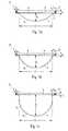
- Figures 1a, 1b and 1crelate to a preferred embodiment of a set of capsules 1A, 1B, 1C according to the invention.
- the capsulespreferably comprise a body 2, a rim 3 and an upper wall member respectively a perforable membrane 4.
- the membrane 4 and the body 2enclose an enclosure respectively ingredients compartment 6.
- the membrane 4is preferably connected onto an inner annular portion R of the rim 3 that is preferably between 1 to 5 mm.
- the membrane 4is connected to the rim 3 of the body by a seal such as a heat or ultrasonic weld line.
- the rimis not necessarily horizontal as illustrated. It can be slightly bended in order to increase the resistance of the seal to the increasing pressure pushing on the membrane with time, due to degassing of the capsule ingredient with time.
- the rim 3 of the capsulespreferably extends outwardly in a direction essentially perpendicular (as illustrated) or slightly inclined (if bended as aforementioned) relative to the axis of rotation Z of the capsule 1 (see figure 3 ).
- the axis of rotation Zrepresents the axis of rotation during centrifugation of the capsule in the brewing device.
- the capsules 1A,1B,1Care preferably single-use capsules. However, it should be noticed that the capsules can deliver more than one beverage at a time, for example, a volume of coffee extract sufficient for filling two cups at a same time.
- the body 2 of the respective capsulehas a single convex portion 5a, 5b, 5c of variable depth, respectively, d1, d2, d3.
- the portion 5a, 5b, 5cmay as well be a continuously truncated or a partially cylindrical portion.
- the capsules 1A, 1B, 1Cpreferably comprise different volumes but a same insertion diameter 'D'.
- the capsule of figure 1ashows a small volume capsule 1A whereas the capsule of figure 1B and 1C show a larger volume capsule 1B respectively 1C.
- the insertion diameter 'D'is hereby determined at the line of intersection between the lower surface of the rim 3 and the upper portion of the body 2. However, it could be another referencing diameter of the capsule in the device.
- the body 2 of the capsulesis preferably rigid or semi-rigid. It can be formed of a food grade plastic, e.g., polypropylene, with a gas barrier layer such as EVOH and the like or aluminium alloy or a laminate of plastic and aluminium alloy.
- the membrane 4can be made of a thinner material such as a plastic film also including a barrier layer or aluminium alloy or a combination of plastic and aluminium alloy.
- the membrane 4is usually of a thickness between 10 and 250 microns, for example.
- the membraneis perforated for creating the water inlet as will be described later in the description.
- the membranealso further comprises a perforable peripheral area.
- the capsules 1A, 1B, 1Cmay as well comprise a rigid or semi-rigid lid member which preferably has the form of a disk of plastic comprising a central portion having an inlet port for enabling the introduction of a water injection member and a peripheral portion having circumferentially arranged outlet openings.
- the volume difference between the small and large capsulesis obtained particularly by varying the depth (d1, d2,d3) of the body 2 of the capsules in the set.
- the depth of the body of the smaller capsule 1Ais lower than the depth of the body of the larger capsules 1B, 1C.
- an equivalent (non illustrated) mode to obtain different volumeswould be to vary the bottom shape of the capsule or other dimensions of the capsule, e.g., its diameter.
- the small volume capsule 1Apreferably contains an amount of extraction ingredient, e.g., ground coffee, smaller than the amount for the large volume capsules 1B, 1C.
- the small capsule 1Ais intended for delivery of a short coffee of between 10 mL and 60 mL with an amount of ground coffee comprised between 4 and 8 grams.
- the larger capsules 1Bis intended for delivery of a medium-size coffee, e.g., between 60 and 120 mL and the largest capsule is intended for delivery of a long-size coffee, e.g., between 120 and 500 mL.
- the medium-size coffee capsule 1Bcan contain an amount of ground coffee comprised between 6 and 15 grams and the long-size coffee capsule 1C can contain an mount of ground coffee between 8 and 30 grams.
- the capsules in the set according to the inventionmay contain different blends of roast and ground coffee or coffees of different origins and/or having different roasting and/or grinding characteristics.
- the geometry of the rim 3may be adapted to comprise, for example, a L-shaped cross section having an annular outer protrusion 8 formed in a direction perpendicular to a plane in which the membrane 4 is arranged.
- the thickness h1, h2, h3 of the rim 3is preferably adapted to the amount and/or characteristics of the beverage substance contained by the shown capsules 1A, 1B, 1C in order to enable an adjustment of the back-pressure exerted onto the capsule when being enclosed by a dedicated enclosing member 15 of a beverage production device.
- capsules containing a small amount of beverage substance - e.g. capsule 1A - in order to prepare e.g. a ristretto or espresso coffee beveragea slow extraction might be desired for providing the coffee with a high intensity (i.e., a large amount of total coffee solids transferred in the coffee extract) and a thick crema.
- a fast extractionmight be desired for providing the coffee with a high intensity (i.e., a large amount of total coffee solids transferred in the coffee extract) and a thick crema.
- the back-pressure of a capsule 1A of a smaller volume containing a smaller amount of substanceis to be adapted to be higher than the backpressure of larger capsule 1B or 1C containing a higher amount of substance.
- the indicated thickness h1 of the valve portion 8 of the rim for capsule 1Ais chosen to be higher than the indicated thickness h2 respectively h3 for capsules 1B respectively 1C.
- the thickness h of the respective capsules 1A, 1B, 1Cis adapted to increase as a function of the volume of capsules and/or the amount of beverage substance contained within the respective capsules.
- the thickness h1is preferably chosen to be between 1.0 and 2.5 mm.
- thickness h2 respectively h3is preferably chosen to be between respectively 0.8 and 1.8 mm and between 0.5 and 1.5.
- such valuescan differ greatly depending on the configuration of the valve means, in particular, on the device side.
- the thicknessmay as well decrease as a function of the volume of beverage substance contained within the capsule, dependent on the force loading means exerting a predefined force on the rim 3 respectively the protrusion 8 of the capsule 1 when the capsule is enclosed in a beverage production device (cf. figures 3 and 4 ).
- force generating meansare provided in the device can be made non-adjustable in order to not change the applied force onto an enclosing member exerting a back-pressure onto the rim of the capsule once the capsule is engaged in the device. Accordingly, an adaptation of the applied back-pressure is preferably solely done by means of the variation of the geometry of the rim of the capsule.
- the width b of protrusion 8delimits radially the valve portion of the rim. It is preferably of equal value for the different embodiments of the capsules 1A, 1B, 1C of the set.
- the thickness (h1, h2, h3) of the rim 3 respectively the annular protrusion 8 of a specific capsulemay not only be adapted with regard to the volume, but also with regard to the nature of the beverage substance (e.g., amount, density, composition, etc.) contained within the capsule such that the back-pressure resulting when the rim 3 of the capsule is engaged with a portion of valve of the dedicated device, is adjusted to a desired value.
- Figures 2a and 2brelate to further preferred embodiments of the capsules according to the present invention.
- the shown embodiments of the capsules 1D and 1Epreferably comprise the same diameter D as capsules 1A, 1B, 1C.
- the capsule 1Dis of frusto-conical form comprising a body 2 having a preferably constant wall thickness t.
- the rim 3 of the capsuleis formed integral with the body 2.
- rim 3 of the capsuleis preferably of essentially rectangular cross section of thickness h and width b.
- thickness h and/or width bare preferably adapted to the type of capsule.
- Thickness hmay be different of the preferably constant wall thickness t of the capsule.
- the membrane 4is sealed to an annular portion R on the upper surface of rim 3 of the capsule.
- the membrane 4may as well be sealed to the complete upper surface of rim 3 such that portion R equals width b.
- Figure 2bshows a further capsule 1E of a set of capsules according to the present invention.
- the geometry of the rim 3is adapted to have a central essentially embossed protrusion 8 protruding above the sealing plane of the upper wall 4 on the rim.
- the thickness "h”(or “h1”, “h2”, “h3”, etc.) is measured from the lower surface of the rim 3 to the highest point of the rim, i.e., when an extension is provided from the highest point of the extension 8 of rim 3.
- the thicknessis anyway the effective distance which is adapted to adjust the back-pressure during the beverage extraction process by insertion of the capsule in the device as will be further explained.
- the capsule rim portion 3may take various geometrical designs in order to influence and adapt at least one brewing parameter during the beverage extraction process.
- Figure 3shows a sectional side view of a device according to the system of the invention in a closed state thereof.
- the devicecomprises a rotating capsule holder 10, a driving means 27, and a collector 11 onto which the centrifuged liquid impacts and drained through a beverage outlet 12.
- the driving means 27can be a rotary motor which is linked to the capsule holder 10 at the bottom side (as illustrated) or top side (not illustrated).
- the devicecomprises water injection means 18 having an injection member 13 being arranged to pierce the membrane 4 of the capsule 1 in a central portion thereof.
- the injection means 18preferably also comprise a series of outlet perforators 24 as described in WO2008/148604 . Accordingly, outlets are produced in an annular portion of the membrane 4 which enable an extracted beverage to leave the capsule 1 during the rotational movement thereof.
- the injection means 18are connected to liquid circuit 22 comprising a liquid supply 21, a pump 20 and heating means 19 for providing a predefined volume of heated pressurized liquid to the capsule 1 during the beverage extraction process.
- the devicefurther comprises a valve portion 15 which is arranged circumferentially to the water injection unit 18 and which has a lower annular pressing surface 15a.
- valve portion 15 and the injection unit 18are preferably movable with respect to the capsule holder 10 in order to enable an insertion and ejection of the capsule 1 to and from the capsule holder 10 before respectively after the beverage extraction process.
- the water injection means 18, the valve portion 15 and the capsule holder 10are rotatable about axis Z.
- valve portion 15is also made moveable independently from the injection unit 18 to take into account the different possible thicknesses of the capsules without affecting the relative position of the injection portion when engaged against the capsule.
- portion 15can be slidably mounted about injection unit 18.
- a relatively small flow restrictionis created that enables to force the flow of centrifuged liquid into a narrow jet of liquid projected onto the impact surface 11 of the device.
- the restrictionforms an annular opening of surface area preferably comprised between 1.0 and 10.0 mm 2 .
- the surface area of the flow restrictioncan vary depending on the set backpressure value in the valve by the capsule and the rotational speed of the capsule wherein in general the higher the speed, the larger the surface area.
- the capsule holder 10has an inner circumferential surface 10b that forms a referencing diameter substantially equal to diameter 'D' of the capsule 1 so as to ensure a tight fit of the capsule in the capsule holder 10 without possible radial play.
- the capsule holder 10is preferably hollow or deep enough at its centre to be able to accommodate all capsules of the set. Accordingly, a unique capsule holder is sufficient to receive all the capsules 1A, 1B, 1C, 1D, 1E of the set.
- the shown collector 11terminates by a beverage outlet 12 such as formed as at least one open duct directed to one or more cups to collect the prepared beverage.
- the capsule holdercan take various shapes and may also be formed of a simple annular hollow ring.
- the capsule 1also lies solidly on its rim 3 onto an upper flange 10a of the capsule holder 10 without the body 2 substantially deforming radially.
- the water injection unit 18 and the valve portion 15are engaged against the membrane 4 and rim, respectively.
- the systemthereby forms a valve 23 by engagement of the valve portion 15 of the device and valve portion 8 of the capsule.
- the valve 23is designed to close under the force of a resilient closure load obtained by a load generating system 16, 17 comprising a preferably spring-biasing element 16.
- the spring-biasing element 16applies a predefined resilient load onto the enclosing member 15.
- the loadprimarily distributes itself along the pressing surface 15a of the valve portion 15 acting in closure against the annular surface of the valve portion of rim 3. Such surface may also be a simple annular contact line. Therefore, the valve 23 normally closes off the flow path for the centrifuged liquid until a sufficient pressure is exerted on the upstream area of the valve by the centrifuged liquid exiting through the orifices created by the perforating elements 24.
- a small liquid leakage through the valve means 23may be required that helps vent the gas or air contained in the capsule during the filling of the capsule with liquid (not shown).
- This leakagemay be obtained by small radial grooves or orifices provided in any of the valve portions (portion 15 of the device and/or rim 3 of the capsule).
- the leakagemay also be obtained by small embossings on the membrane 4 to create a leak.
- the small embossingscould be on the surface of the valve portion 15. The liquid flows thus between the membrane 4 and the valve portion 15 and forces the valve 23 to open by pushing the whole enclosing member 15 upwards against the force of the spring-biasing element 16.
- the centrifuged liquidcan thus transverse the restriction created between the surface 15a of the portion 15 and the upper surface or line of the rim 3 or protruding portion 18.
- the liquidis thus ejected at a high velocity against the collector 11 as indicated by arrow A in Fig. 3 or another vertically oriented annular wall of the device placed between the collector and the valve 23 (not shown).
- the force acting on the rim 3 of the capsule 1 by pressing surface 15acan be adjusted by the geometry of the rim 3 such as e.g. the thickness h of the rim 3.
- the exerted back-pressure acting on the rim 3can be adjusted by adapting the thickness h of the rim 3 to predefined values thereof.
- a higher back-pressurecan be obtained by a larger thickness h, since this leads to a higher compression of the spring biasing element 16 which then exerts a higher force onto the pressing surface 15a.
- a lower value for thickness hleads to a lower compression of the spring biasing element 16 and thus, to a relative lower force acting on the pressing surface 15a, so a lower back-pressure.
- the thickness his preferably designed to increase for obtaining a resulting higher back-pressure.
- the resulting flow rateis set e.g. dependent on the type of capsules (e.g., 1A, 1B or 1C) inserted in the device.
- the present inventionconstitutes a built-in solution according to which the spring load of the enclosing member 15 enclosing the capsule 1 in a device does not have to be externally manipulated for each beverage preparation procedure in which a beverage of different nature is to be prepared.
- the spring loadis preferably held at a constant predefined value in order to enable an accurate adjustment of the back-pressure by means of the variation of the geometry of the rim 3 of the capsule.
- the capsule 1may as well include identifying means to control brewing parameters and/or interact with the beverage production device.
- the identifying meanspreferably enable to provide information about the type of capsule engaged in the beverage production device. Accordingly, brewing parameters the volume and/or the rotational speed at which the beverage is prepared may be automatically adjusted by the device dependent on the provided information of the capsule. Customization options may also be provided to the user for enabling the modification by the user of certain extraction parameters within given ranges.
- the portion of valve of rim 3 of the capsule 1may be designed to form an identifying means that provides a discriminable information to the device as a function of its geometry, e.g., its particular thickness.
- the devicepreferably comprises sensing means 26 designed to interact with the identifying means of the capsule.
- the sensing means 26 of the devicecan be a pressure sensor connected to the load generating means 16, 17 of the device.
- the sensing means 26are preferably connected to a control means 25 of the device in order to provide information related to the present back-pressure acting onto the rim 3 of the engaged capsule, i.e., pressure or force value.
- the control means 25are preferably connected to at least the drive means 27, the pump 20 and the heating means 19.
- the brewing parameterssuch as the rotational speed of the motor 27, the temperature, the pressure and/or the volume of the liquid provided to the capsule during the beverage production process may be adjusted dependent on the provided information of the sensing means 26.
- the thickness h of the rim 3is designed to vary the resulting back-pressure of valve 23 in order to adapt the brewing parameters of the particular beverage to be prepared.
- the rotational speedis adjusted at the desired value that corresponds to a desired flow rate.
- different speeds or speed rangescan be selected as function of the sensed information by the sensing means 26. Selection of the speed is provided in the control unit 25 which controls in return the rotary motor 26 and if necessary the flow rate of the pump 20 to ensure sufficient supply of liquid in the capsule as a function of the selected speed.
- the pressure sensing meanscan be replaced by one or more distance sensors.
- the thickness h of the rimcan be sensed directly or indirectly.
- the length variation of the load generating means 16, 17e.g. spring length
- the control unit 25for adjusting the brewing parameters, e.g., the rotation speed and/or volume of injected liquid.
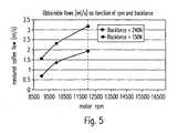
- the flow control principle of the inventionis illustrated in Fig. 5 .
- the graphicillustrates the evolution of the beverage flow rate, e.g., coffee flow rate, (in mL/sec) as a function of the rotation speed of the motor (in rpm) for two different capsules (i.e. backforces).
- the backforceis here the force exerted by the annular pressing surface 15a, due to the compression of the spring loading member 16 of the device, onto the capsule's rim contact surface of portion 8 considering that the pressing surface in contact with the contact surface of portion 8 represents about 186 mm 2 .
- the lower curverepresents a capsule setting a backforce of 240 Newton (or a backpressure of 1.29 Mpa or 12.9 bar).
- the upper curverepresents another capsule with a smaller thickness of its portion 8 setting consequently a lower backforce of only 150 Newton (or a backpressure of 0.819 Mpa or 8.19 bar).
- the flow ratecan be set within a large range, e.g., 0.5 to 3.5 mL/sec for both capsules while maintaining a relatively narrow range of rotational speed, i.e., 9000 to 12000 rpm. If only a single capsule would be utilized providing a single backforce of 150 Newton, the same flow range would be covered only with a much larger range of speeds, i.e., between 9000 and more than 16500 rpm. Therefore, the invention provides larger opportunities of tailoring beverage characteristics with a much larger range of flow rate. In particular, one advantage can also be to reduce the useful speed range while maintaining the opportunity to deliver beverages within a larger range of flow rate.
- Figure 4relates to another preferred embodiment of a device according to the present invention showing a sectional side view of the valve means 23 constituted by the rim portion 3 enclosed by the capsule holder 10 and the valve portion 15 of the device.
- the obtained back-pressureis obtained due to load generating means 16 which in this embodiment comprise two magnets M arranged in the valve portion 15 and the capsule holder 10 respectively.
- the magnets Mmay be circumferentially arranged about axis Z of the device (see figure 3 ) in order to enable a uniform force distribution between the enclosing member 15 and the capsule holder 10 enclosing the rim 3 of the capsule.
- the resulting back-pressuredecreases for an increasing thickness h of the rim 3, since the attracting forces between the two opposed magnets M decrease if the distance between the magnets is increased. This has to be considered for the design of the height h of the rim. Hence, in such an embodiment, the height h is decreased in order to obtain a higher resulting back-pressure acting between the enclosing member 15 and the capsule holder 10 respectively the rim 3 of the capsule 1.
- the valve as obtained by the cooperation of the capsules and devicecan be replaced by a valve as part of the capsule only.
- the valveis geometrically designed for at least two types of capsules, preferably each type of capsules of the set, to provide different backpressures for the centrifuged liquid.
- the backpressureis obtained by a fixed restriction such as by at least one, but preferably a plurality of radially positioned outlet orifices provided through the capsule, whose total opening surface area varies in function of the type of capsule in the set.
- the restriction orificesprovide a backpressure which is function of the number of outlet orifices and the individual opening section of each orifice.
- orificescan be provided along a circular path through the upper wall of the capsule or an annular path through the sidewall of the capsule.
- the total surface area of the flow restrictioncan represent between 0.5 and 5.0 mm 2 , more preferably between 0.75 and 3.0 mm2, most preferably between 1.0 and 2.5 mm 2 , for example, at about 1.7 mm 2 .
- the number of outlet orifices for creating the flow restriction in the periphery of the capsulecan range of from 1 to 300, more preferably between 3 and 150.
- a first capsulecomprises a flow restriction formed of 10 orifices of each 0.2 mm 2 and a second capsule with a flow restriction of 15 orifices of each 0.2 mm 2 .
- a first capsulecomprises a flow restriction formed of 10 orifices of each 0.2 mm 2 and a second capsule with a restriction of 10 orifices of each 0.25 mm 2 .
- the first capsulesprovide a function of flow rate to pressure which differs from the second capsules.
- the first capsulesprovide a higher backpressure for the centrifuged liquid than the second capsules.
- the rotational speedcan be controlled at specific values to ensure a flow rate for the first and second capsules that corresponds to the characteristics of the beverage to be produced.
- other capsule typescan be designed in the set of capsules to ensure other different backpressure characteristics.
Landscapes
- Engineering & Computer Science (AREA)
- Mechanical Engineering (AREA)
- Food Science & Technology (AREA)
- Apparatus For Making Beverages (AREA)
- Centrifugal Separators (AREA)
Description
- The present invention relates to a system for preparing a beverage from a beverage substance contained in the capsule by passing a liquid through the substance using centrifugal forces.
- In particular, the present invention relates to a system and a device with flow adjustment means enabling to adjust the flow rate and/or the back-pressure during a beverage production with the device.
- It exist systems for preparing beverages such as coffee by forcing a liquid through ingredients contained in the capsule using centrifugal forces.
WO 2008/148604 for example relates to a capsule for preparing a beverage or liquid food from a substance, in a centrifugal brewing unit, by passing water through the substance contained in the capsule by using brewing centrifugal forces comprising: an enclosure containing a predetermined dose of substance; opening means which opens under the centrifugal effect to allow the brewed liquid to leave the capsule. The capsule may also comprise means for engaging the capsule to external rotational driving means of a centrifugal brewing device wherein the engaging means are configured to offer a resistance to torque during rotation of the capsule for maintaining the capsule in a reference rotational position.WO 2009/106598 relates to a capsule system similar to the one of the present invention.- Thereby, the effect of centrifugal forces to brew coffee or prepare other food substances presents many advantages compared to the normal brewing methods using pressure pumps. For example, in traditional espresso or lungo coffee type brewing methods using a pressure pump, it is very difficult to master all the parameters which influence the quality of extraction of delivered coffee extract. These parameters are typically the pressure, the flow rate which decreases with the pressure, the compaction of the coffee powder which also influences the flow characteristics and which depends on the coffee ground particle size, the temperature, the water flow distribution and so on. In particular, it is not easy to vary the extraction pressure and flow rates because there are essentially determined by the static pressure deliverable by the pump, the resistance of the bed of coffee and the downstream filtering system.
- For a centrifugal extraction, the rotating capsule is used as a centrifugal pump. The rotational speed thus determines the flow rate of the centrifuged liquid coming out of the capsule. The quality of the beverage to be prepared depends on the control, in particular, of the flow rate. In particular, the flow rate is influenced by two parameters: the rotational speed of the capsule in the device and the back-pressure exerted on the centrifuged liquid before it is projected out of the capsule. For a given back-pressure, the higher the rotational speed, the larger the flow rate. Conversely, for a given rotational speed, the larger the back-pressure, the smaller the flow.
- Whereas the rotational speed of the capsule is usually controlled by control means selectively activating a rotational motor of a centrifugal beverage production device, a predefined back-pressure is preferably obtained by a flow restriction of the centrifuged liquid at the outlet of the capsule or at the outside of a centrifugal cell carrying the capsule.
- For example
EP 651 963 document FR 2 487 661 WO 2006/112691 relate to centrifugal systems wherein a fixed restriction is placed downstream of the filter to create a pressure gradient. - Moreover,
WO 2008/148646 proposes a solution in which a flow restriction is placed in or outside the centrifugal cell. The flow restriction can comprise a regulating spring biased valve offering an effective back-pressure. The spring biased valve opens under the effect of a sufficient pressure of liquid exerting on the valve. The higher the speed, the larger the passage through the valve, and the higher the flow rate. The valve can be preloaded by a resilient element such as rubber or spring elements. - Therefore is a need for being able to provide beverages, (e.g. coffee) having different characteristics of intensity, taste, aroma, foam/crema in a system that is simple and versatile.
- For prior art system without back-pressure regulation, the problem is that the flow can be increased only by increasing the centrifugation speed. Therefore, this creates limits to vary the flow rate of the beverage, thereby also limiting the possibility to deliver beverages of different characteristics. Furthermore, too high rotational speeds may create problems such as noise, vibration and premature wearing of the mechanical pieces of the device.
- Therefore, there is a need for proposing a new system for which the brewing parameters and in particular the back-pressure and/or the flow rate during the beverage preparation be better and more independently controlled for improving quality of the delivered food liquid.
- The present invention provides a solution to the beforementioned problems as well as offers additional benefits to the existing art.
- A first aspect of the invention relates to a capsule system for preparing beverages by centrifugation of a capsule in a centrifuging brewing device comprising:
- a centrifuging brewing device comprising control means capable of operating the device in centrifugation by controlling the beverage flow rate and/or the volume of the beverage, and
- a capsule to be inserted in the brewing device,
- The term "back-pressure of the valve means" refers to the pressure loss created by the restriction or restriction valve. As the restriction or restriction valve form a "bottleneck effect", a pressure of liquid is created upstream of it by the effect of the centrifugation. Thanks to the restriction, the pressure before the restriction is increased, and it is this pressure which has an effect on the interaction (e.g. extraction) process of the liquid and the ingredients). This pressure of the restriction valve can also be defined as the ratio of force ("backforce") in particular which the spring loaded surface of the beverage production device exerts on the capsule, divided by the area of contact surface at the restriction valve.
- In a preferred mode, the capsule comprises a rim portion which is designed to interact with an enclosing member of the brewing device to form a flow restriction valve which exerts a back-pressure onto the rim of the capsule.
- The centrifugal forces created by rotating the liquid hitting the restriction valve produce a pressurization of the liquid upfront the valve. Once this pressure reaches a threshold value, the valve will start to open, i.e. the rim of the capsule will be slightly distanced from the cooperating surface of the beverage production device.
- The adjustment of the rotational centrifugation speed may be a selection amongst at least two, preferably at least three, different values or ranges of rotational speed of the capsule enabling release of centrifuged liquid from the capsule through the valve means.
- The rotational speed may be adjusted during release of the centrifuged liquid to match a reference flow rate of the injected liquid in the capsule.
- In a possible mode, the rotational speed may be adjusted during release of the centrifuged liquid to match a reference pressure of the injected liquid in the capsule. The pressure of the injected liquid can be measured in any convenient location in the fluid line between the pump and the capsule.
- The predefined values of the rotational speed of the capsule may additionally be altered by a user operation within a given range.
- The predefined values of the rotational speed of the capsule may be, preferably automatically, adjusted by means of a physical feature of the capsule.
- In particular, the geometry of the rim of the capsule may be designed to vary the value of the exerted backpressure of the flow restriction valve.
- More particularly, the thickness of the rim may differ for at least for two different capsules, preferably at least three different capsules, thereby calibrating at least two different back-pressures of the valve means. In particular, calibrating is carried out by engagement of the rim of the capsule with a spring-biased valve portion of the beverage device.
- The thickness of the rim may be increased or decreased as a function of the storage volume and/or the weight of the beverage substance enclosed in the capsule and/or the type of beverage to be prepared.
- The value of the thickness of the rim of the capsule may vary between 0.2 and 5 mm depending of the type of capsule.
- Moreover, the rim of the capsule may be formed integral with the body of the capsule in a direction essentially perpendicular to an axis of rotation of the capsule.
- A further aspect of the invention relates to a centrifuging brewing device for preparing beverages by centrifugation of a capsule, comprising
a rotary capsule holder of the brewing device for holding a capsule,
rotary drive means to drive the capsule in rotational centrifugation,
injection means for injecting liquid in the capsule, wherein the injection means are connected to a pump,
the device further comprising control means connected to at least the rotary drive means and the pump which are designed to vary the flow rate of the beverage and/or the volume of the beverage,
wherein the device further comprises backpressure related sensing means connected to the control means and designed for sensing directly or indirectly the backpressure of a flow restriction or a flow restriction valve provided in the capsule or provided by cooperation of the capsule with the centrifuging brewing device. - The control means may be configured to adjust the rotational speed of the drive means dependent on the sensed backpressure.
- The control means may be designed to vary the injected volume of liquid into the capsule dependent on the sensed back-pressure.
- The control means can adjust the starting rotation speed for the extraction. The rotation speed can be varied during extraction, in particular, to ensure a control of a flow rate of reference during extraction.
- The flow restriction valve may comprise an engaging portion and a spring biasing means forcing the engaging portion onto the rim portion of the capsule.
- In a first possible mode the back-pressure sensing means may comprise at least one pressure sensor configured for measuring the backpressure exerted by the engaging portion onto the rim of the capsule.
- In a second possible mode, the back-pressure detection means may comprise at least one distance sensor for detecting a variation of the compression distance in the valve means reflecting indirectly the backpressure.
- The centrifuging brewing device may furthermore comprise a flow metering means for sensing the flow rate of the liquid supplied to the capsule and adjusting the flow by varying the rotational speed to match a flow rate of reference.
- The capsules according to the system of the present invention may further comprise additional capsule identifying means associated to the different capsules in the set for adjusting at least one brewing parameter chosen amongst the list consisting of: liquid temperature, pump flow rate, rotational speed, liquid volume, water pressure, prewetting time and combinations thereof. Such additional capsule identifying means can be a barcode, RFID, colour recognition, ferro-magnetic element, mechanical prongs and combinations thereof.
- The device of the invention thereby comprises a reader suitable for reading the additional identifying means of the capsule. The reader is connected to the control unit of the device for controlling the different means of the device in response to the detected capsule. The reader is adapted to read a code chosen amongst the list of: a barcode, RFID, colour recognition, ferro-magnetic element, mechanical prongs and combinations thereof.
- Preferably, the back-pressure (i.e. the pressure above the atmospheric pressure) exerted by the restriction or valve means can range between 5 N/cm2 (0.5 bar) and 180 N/cm2 (18 bar), more preferably between 15 N/cm2 (1.5 bar) and 134 N/cm2 (13.4 bar), most preferably between 27 N/cm2 (2.7 bar) and 87 N/cm2 (8.7 bar) depending on the type of capsule.
- The restriction created by the valve in the open configuration or by orifice(s) is preferably controlled by design of the capsule and/or device to be comprised between 0.5 and 4.0 mm2, more preferably between 0.75 and 3.0 mm2, most preferably between 1.0 and 2.5 mm2, for example, at about 1.7 mm2.
- The rotational speed is preferably controlled between a range of from 2000 and 16500 rpm, most preferably between 4000 and 10000 rpm. For at least two capsules of the set, preferably for at least three capsules of the set, at least one rotational speed is different during centrifugation of the liquid in the capsule, within the controlled range.
- The flow rate is preferably controlled to range between 0.1 and 10 ml/seconds, more preferably between 0.5 and 3.5 ml/seconds. Again for at least two capsules of the set, preferably for at least three capsules of the set, at least one flow rate is different during centrifugation of the liquid in the capsule.
- In another mode of the invention, the set of capsules comprises the flow restriction valve as a whole. In other words, the valve is not obtained by the conjunction of a valve portion of the capsule and a valve portion of the capsule but it is obtained by portions of the capsule itself. An example of a capsule having such kind of restriction valve is described in
WO2008/148604 which content is here included by reference. In the cited publication, the restriction valve is referred as an opening means which opens under the centrifugal effect to allow the brewed liquid to leave the capsule. The opening or valve means can comprise a resilient valve. For instance, the opening means comprises at least one radial deflecting lip integral to a wall of the capsule. For instance, a lid of the capsule is connected to a body and the deflectable lip is part of the lid. The lip has precise dimensions to provide a predetermined opening pressure. In the context of the present invention, the opening or restriction valve is configured to provide a closing pressure of the valve for the centrifuged liquid which varies for at least two capsules, preferably at least three capsules of the set and/or is configured to open to form a restriction area in the open configuration of the valve that differs for at least two capsules, preferably at least three capsules of the set. As a result the pressure loss created by the valve means differs for at least two capsules, and preferably at least three capsules, of the set. - It should also be noticed that the portions in contact of the valve can be on the capsule itself but the spring-biasing means be on the device for urging the portions of the capsule in closure together. The valve would still be part of the capsule but the closure force of the valve setting the backpressure be assured by the device.
- In another mode, the capsules have flow restriction orifices (i.e., replacing the flow restriction valve as aforementioned) which overall surface area increases in the set of capsules as a function of the increase of the amount of powder and/or size of capsule in the set. Therefore, the larger the capsule, the larger the flow area for the centrifuged liquid in the capsule and consequently the lower the backpressure exerted by the restriction orifices. Furthermore, the rotational speed is also set in the device to increase when the amount of coffee powder decreases in the capsules and/or the size of the capsules decreases. The sensing means may be adapted to sense the backpressure upstream of said restriction.
- In a preferred embodiment, the capsules according to the system of the invention contain coffee powder of different sorts to produce coffee beverages having characteristics (strength, aroma, taste, crema,...) and different volumes, e.g., 25, 40, 110, 250, 400 mL (e.g., ristretto, espresso, lungo, doppio, Americano, Long black etc) with preferably variable crema characteristics (volume and/or texture).
- By "different sorts" of a beverage substance or coffee it is meant any difference regarding: weight in the capsule, grind size, tap density, roasting levels, origins, blends, nature of ingredients (coffee, tea, cocoa, additives, etc.) and combinations thereof.
- Further features, advantages and objects of the present invention will become apparent for a skilled person when reading the following detailed description of embodiments of the present invention, when taken in conjunction with the figures of the enclosed drawings.
- Fig. 1a - 1c
- are cross sectional side views of different embodiments of a capsule having different sizes according to the invention and a variation of height of their rim.
- Fig. 2a and 2b
- are cross sectional side views of further embodiments of a capsule of the system having a rim portion of different configuration.
- Fig. 3
- is a schematic representation of the centrifugal device into which is inserted a capsule according to the invention, wherein the back-pressure is exerted by spring loading means.
- Fig. 4
- is a sectional side view of the centrifugal device into which is inserted a capsule according to the invention, wherein the back-pressure is exerted by magnetic means.
- Fig. 5
- is a graphical representation of the coffee flow rates obtainable with two different capsules providing different back-pressures as a function of the rotational speed of the capsule in the centrifugation device.
Figures 1a, 1b and 1c relate to a preferred embodiment of a set ofcapsules body 2, arim 3 and an upper wall member respectively aperforable membrane 4. Thereby themembrane 4 and thebody 2 enclose an enclosure respectivelyingredients compartment 6. As shown in the figures, themembrane 4 is preferably connected onto an inner annular portion R of therim 3 that is preferably between 1 to 5 mm. Themembrane 4 is connected to therim 3 of the body by a seal such as a heat or ultrasonic weld line.- The rim is not necessarily horizontal as illustrated. It can be slightly bended in order to increase the resistance of the seal to the increasing pressure pushing on the membrane with time, due to degassing of the capsule ingredient with time.
- The
rim 3 of the capsules preferably extends outwardly in a direction essentially perpendicular (as illustrated) or slightly inclined (if bended as aforementioned) relative to the axis of rotation Z of the capsule 1 (seefigure 3 ). Thereby, the axis of rotation Z represents the axis of rotation during centrifugation of the capsule in the brewing device. - It should be understood that the shown embodiment is just an exemplary embodiment and that the
capsule 1 in particular thecapsule body 2 according to the invention can take various different embodiments. - The
capsules - The
body 2 of the respective capsule has a singleconvex portion portion - Hence, the
capsules figure 1a shows asmall volume capsule 1A whereas the capsule offigure 1B and 1C show a larger volume capsule 1B respectively 1C. The insertion diameter 'D' is hereby determined at the line of intersection between the lower surface of therim 3 and the upper portion of thebody 2. However, it could be another referencing diameter of the capsule in the device. - The
body 2 of the capsules is preferably rigid or semi-rigid. It can be formed of a food grade plastic, e.g., polypropylene, with a gas barrier layer such as EVOH and the like or aluminium alloy or a laminate of plastic and aluminium alloy. Themembrane 4 can be made of a thinner material such as a plastic film also including a barrier layer or aluminium alloy or a combination of plastic and aluminium alloy. Themembrane 4 is usually of a thickness between 10 and 250 microns, for example. The membrane is perforated for creating the water inlet as will be described later in the description. The membrane also further comprises a perforable peripheral area. - Instead of the
membrane 4, thecapsules - The volume difference between the small and large capsules is obtained particularly by varying the depth (d1, d2,d3) of the
body 2 of the capsules in the set. In particular, the depth of the body of thesmaller capsule 1A is lower than the depth of the body of thelarger capsules 1B, 1C. - Of course, an equivalent (non illustrated) mode to obtain different volumes would be to vary the bottom shape of the capsule or other dimensions of the capsule, e.g., its diameter.
- The
small volume capsule 1A preferably contains an amount of extraction ingredient, e.g., ground coffee, smaller than the amount for thelarge volume capsules 1B, 1C. Hence, thesmall capsule 1A is intended for delivery of a short coffee of between 10 mL and 60 mL with an amount of ground coffee comprised between 4 and 8 grams. The larger capsules 1B is intended for delivery of a medium-size coffee, e.g., between 60 and 120 mL and the largest capsule is intended for delivery of a long-size coffee, e.g., between 120 and 500 mL. Furthermore, the medium-size coffee capsule 1B can contain an amount of ground coffee comprised between 6 and 15 grams and the long-size coffee capsule 1C can contain an mount of ground coffee between 8 and 30 grams. - In addition, the capsules in the set according to the invention may contain different blends of roast and ground coffee or coffees of different origins and/or having different roasting and/or grinding characteristics.
- As indicated in
figures 1a to 1c , the geometry of therim 3 may be adapted to comprise, for example, a L-shaped cross section having an annularouter protrusion 8 formed in a direction perpendicular to a plane in which themembrane 4 is arranged. Thereby, the thickness h1, h2, h3 of therim 3 is preferably adapted to the amount and/or characteristics of the beverage substance contained by the showncapsules member 15 of a beverage production device. - In particular, for capsules containing a small amount of beverage substance -
e.g. capsule 1A - in order to prepare e.g. a ristretto or espresso coffee beverage, a slow extraction might be desired for providing the coffee with a high intensity (i.e., a large amount of total coffee solids transferred in the coffee extract) and a thick crema. These characteristics can be compared to a faster extraction which might be desired for the beverage coming out ofcapsules 1B or 1C containing a larger amount of coffee powder. Therefore, for a given rotational speed during the beverage extraction, the back-pressure of acapsule 1A of a smaller volume containing a smaller amount of substance is to be adapted to be higher than the backpressure oflarger capsule 1B or 1C containing a higher amount of substance. Accordingly, the indicated thickness h1 of thevalve portion 8 of the rim forcapsule 1A is chosen to be higher than the indicated thickness h2 respectively h3 for capsules 1B respectively 1C. Hence, the thickness h of therespective capsules - For example, for smaller-size capsules as indicated by
figure 1a , the thickness h1 is preferably chosen to be between 1.0 and 2.5 mm. For bigger-size capsules as indicated byfigures 1b and 1c , thickness h2 respectively h3 is preferably chosen to be between respectively 0.8 and 1.8 mm and between 0.5 and 1.5. Of course such values can differ greatly depending on the configuration of the valve means, in particular, on the device side. - However, as will be later explained with reference to
figure 4 below, it is to be noted that the thickness may as well decrease as a function of the volume of beverage substance contained within the capsule, dependent on the force loading means exerting a predefined force on therim 3 respectively theprotrusion 8 of thecapsule 1 when the capsule is enclosed in a beverage production device (cf.figures 3 and 4 ). - Furthermore, it is to be noted that force generating means are provided in the device can be made non-adjustable in order to not change the applied force onto an enclosing member exerting a back-pressure onto the rim of the capsule once the capsule is engaged in the device. Accordingly, an adaptation of the applied back-pressure is preferably solely done by means of the variation of the geometry of the rim of the capsule.
- As shown in
figures 1a to 1c , the width b ofprotrusion 8 delimits radially the valve portion of the rim. It is preferably of equal value for the different embodiments of thecapsules - It is to be understood that the thickness (h1, h2, h3) of the
rim 3 respectively theannular protrusion 8 of a specific capsule may not only be adapted with regard to the volume, but also with regard to the nature of the beverage substance (e.g., amount, density, composition, etc.) contained within the capsule such that the back-pressure resulting when therim 3 of the capsule is engaged with a portion of valve of the dedicated device, is adjusted to a desired value. Figures 2a and 2b relate to further preferred embodiments of the capsules according to the present invention. Thereby, the shown embodiments of thecapsules capsules - As shown in
figure 2a , thecapsule 1D is of frusto-conical form comprising abody 2 having a preferably constant wall thickness t. Thereby, therim 3 of the capsule is formed integral with thebody 2. As indicated in the figure,rim 3 of the capsule is preferably of essentially rectangular cross section of thickness h and width b. Thereby, thickness h and/or width b are preferably adapted to the type of capsule. Thickness h may be different of the preferably constant wall thickness t of the capsule. - In the shown embodiment, the
membrane 4 is sealed to an annular portion R on the upper surface ofrim 3 of the capsule. However, themembrane 4 may as well be sealed to the complete upper surface ofrim 3 such that portion R equals width b. Figure 2b shows afurther capsule 1E of a set of capsules according to the present invention. In this embodiment the geometry of therim 3 is adapted to have a central essentially embossedprotrusion 8 protruding above the sealing plane of theupper wall 4 on the rim.- In the context of the invention, the thickness "h" (or "h1", "h2", "h3", etc.) is measured from the lower surface of the
rim 3 to the highest point of the rim, i.e., when an extension is provided from the highest point of theextension 8 ofrim 3. - The thickness is anyway the effective distance which is adapted to adjust the back-pressure during the beverage extraction process by insertion of the capsule in the device as will be further explained.
- As illustrated with regard to
figures 1a to 1c and2a and 2b , thecapsule rim portion 3 may take various geometrical designs in order to influence and adapt at least one brewing parameter during the beverage extraction process. Figure 3 shows a sectional side view of a device according to the system of the invention in a closed state thereof. Thereby, the device comprises arotating capsule holder 10, a driving means 27, and acollector 11 onto which the centrifuged liquid impacts and drained through abeverage outlet 12. The driving means 27 can be a rotary motor which is linked to thecapsule holder 10 at the bottom side (as illustrated) or top side (not illustrated).- Furthermore, the device comprises water injection means 18 having an
injection member 13 being arranged to pierce themembrane 4 of thecapsule 1 in a central portion thereof. The injection means 18 preferably also comprise a series of outlet perforators 24 as described inWO2008/148604 . Accordingly, outlets are produced in an annular portion of themembrane 4 which enable an extracted beverage to leave thecapsule 1 during the rotational movement thereof. The injection means 18 are connected toliquid circuit 22 comprising aliquid supply 21, apump 20 and heating means 19 for providing a predefined volume of heated pressurized liquid to thecapsule 1 during the beverage extraction process. - The device further comprises a
valve portion 15 which is arranged circumferentially to thewater injection unit 18 and which has a lower annularpressing surface 15a. - The
valve portion 15 and theinjection unit 18 are preferably movable with respect to thecapsule holder 10 in order to enable an insertion and ejection of thecapsule 1 to and from thecapsule holder 10 before respectively after the beverage extraction process. - Moreover, the water injection means 18, the
valve portion 15 and thecapsule holder 10 are rotatable about axis Z. - The
valve portion 15 is also made moveable independently from theinjection unit 18 to take into account the different possible thicknesses of the capsules without affecting the relative position of the injection portion when engaged against the capsule. For this,portion 15 can be slidably mounted aboutinjection unit 18. - In open configuration of the valve, a relatively small flow restriction is created that enables to force the flow of centrifuged liquid into a narrow jet of liquid projected onto the
impact surface 11 of the device. The restriction forms an annular opening of surface area preferably comprised between 1.0 and 10.0 mm2. The surface area of the flow restriction can vary depending on the set backpressure value in the valve by the capsule and the rotational speed of the capsule wherein in general the higher the speed, the larger the surface area. - The
capsule holder 10 has an innercircumferential surface 10b that forms a referencing diameter substantially equal to diameter 'D' of thecapsule 1 so as to ensure a tight fit of the capsule in thecapsule holder 10 without possible radial play. - The
capsule holder 10 is preferably hollow or deep enough at its centre to be able to accommodate all capsules of the set. Accordingly, a unique capsule holder is sufficient to receive all thecapsules collector 11 terminates by abeverage outlet 12 such as formed as at least one open duct directed to one or more cups to collect the prepared beverage. - It should be noted that the capsule holder can take various shapes and may also be formed of a simple annular hollow ring.
- The
capsule 1 also lies solidly on itsrim 3 onto anupper flange 10a of thecapsule holder 10 without thebody 2 substantially deforming radially. In this configuration, thewater injection unit 18 and thevalve portion 15 are engaged against themembrane 4 and rim, respectively. The system thereby forms avalve 23 by engagement of thevalve portion 15 of the device andvalve portion 8 of the capsule. - The
valve 23 is designed to close under the force of a resilient closure load obtained by aload generating system element 16. The spring-biasingelement 16 applies a predefined resilient load onto the enclosingmember 15. The load primarily distributes itself along thepressing surface 15a of thevalve portion 15 acting in closure against the annular surface of the valve portion ofrim 3. Such surface may also be a simple annular contact line. Therefore, thevalve 23 normally closes off the flow path for the centrifuged liquid until a sufficient pressure is exerted on the upstream area of the valve by the centrifuged liquid exiting through the orifices created by the perforatingelements 24. It should be noted that a small liquid leakage through the valve means 23 may be required that helps vent the gas or air contained in the capsule during the filling of the capsule with liquid (not shown). This leakage may be obtained by small radial grooves or orifices provided in any of the valve portions (portion 15 of the device and/orrim 3 of the capsule). The leakage may also be obtained by small embossings on themembrane 4 to create a leak. The small embossings could be on the surface of thevalve portion 15. The liquid flows thus between themembrane 4 and thevalve portion 15 and forces thevalve 23 to open by pushing the whole enclosingmember 15 upwards against the force of the spring-biasingelement 16. The centrifuged liquid can thus transverse the restriction created between thesurface 15a of theportion 15 and the upper surface or line of therim 3 or protrudingportion 18. The liquid is thus ejected at a high velocity against thecollector 11 as indicated by arrow A inFig. 3 or another vertically oriented annular wall of the device placed between the collector and the valve 23 (not shown). - Thereby, extraction of the beverage out of the
capsule 1 is obtained by driving theinjection unit 18, thevalve portion 15 and thecapsule holder 10 together with the capsule, in rotation (Y) about axis Z, at an extraction speed, e.g., between 500 and 16500 rpm. The rotation is driven by a rotational motor 28 connected to at least thecapsule holder 10 orinjection unit 18. Hence, during operation of thecapsule 1 placed into the system according to the invention, thecapsule 1 is rotated about its axis Z. Thereby, liquid which is centrally injected into thecapsule 1 would tend to be guided along the inner surface of the side wall of thebody 2, up to the inner side of themembrane 4, and then through the perforated outlet filtering openings created in themembrane 4 by the perforatingmembers 24. Due to the centrifugation of the liquid in thecapsule 1, the liquid and the ingredients or substance provided within the capsule are made to interact in order to form a liquid comestible (e.g., liquid extract). - It is to be understood that the force acting on the
rim 3 of thecapsule 1 by pressingsurface 15a can be adjusted by the geometry of therim 3 such as e.g. the thickness h of therim 3. Hence, in particular the exerted back-pressure acting on therim 3 can be adjusted by adapting the thickness h of therim 3 to predefined values thereof. Thereby, a higher back-pressure can be obtained by a larger thickness h, since this leads to a higher compression of thespring biasing element 16 which then exerts a higher force onto thepressing surface 15a. Correspondingly, a lower value for thickness h leads to a lower compression of thespring biasing element 16 and thus, to a relative lower force acting on thepressing surface 15a, so a lower back-pressure. Hence, the thickness h is preferably designed to increase for obtaining a resulting higher back-pressure. - Accordingly, in a simple mode of the invention, due to a particular adjustment of the back-pressure, as described, the resulting flow rate is set e.g. dependent on the type of capsules (e.g., 1A, 1B or 1C) inserted in the device.
- Thereby, the present invention constitutes a built-in solution according to which the spring load of the enclosing
member 15 enclosing thecapsule 1 in a device does not have to be externally manipulated for each beverage preparation procedure in which a beverage of different nature is to be prepared. Instead, the spring load is preferably held at a constant predefined value in order to enable an accurate adjustment of the back-pressure by means of the variation of the geometry of therim 3 of the capsule. Hence, a more convenient and reliable adjustment of the back-pressure onto thecapsule 1 during beverage brewing in a system according to the present invention is enabled. - In a more sophisticated mode of the invention, the
capsule 1 may as well include identifying means to control brewing parameters and/or interact with the beverage production device. - Thereby, the identifying means preferably enable to provide information about the type of capsule engaged in the beverage production device. Accordingly, brewing parameters the volume and/or the rotational speed at which the beverage is prepared may be automatically adjusted by the device dependent on the provided information of the capsule. Customization options may also be provided to the user for enabling the modification by the user of certain extraction parameters within given ranges.
- In a preferred embodiment, the portion of valve of
rim 3 of thecapsule 1 may be designed to form an identifying means that provides a discriminable information to the device as a function of its geometry, e.g., its particular thickness. Thereby, the device preferably comprises sensing means 26 designed to interact with the identifying means of the capsule. - As illustrated in
Fig. 3 , the sensing means 26 of the device can be a pressure sensor connected to the load generating means 16, 17 of the device. The sensing means 26 are preferably connected to a control means 25 of the device in order to provide information related to the present back-pressure acting onto therim 3 of the engaged capsule, i.e., pressure or force value. Thereby, the control means 25 are preferably connected to at least the drive means 27, thepump 20 and the heating means 19. Thus, the brewing parameters such as the rotational speed of themotor 27, the temperature, the pressure and/or the volume of the liquid provided to the capsule during the beverage production process may be adjusted dependent on the provided information of the sensing means 26. In particular, the thickness h of therim 3 is designed to vary the resulting back-pressure ofvalve 23 in order to adapt the brewing parameters of the particular beverage to be prepared. Furthermore, in function of the sensed information by thepressure sensors 26, the rotational speed is adjusted at the desired value that corresponds to a desired flow rate. As a result, different speeds or speed ranges can be selected as function of the sensed information by the sensing means 26. Selection of the speed is provided in thecontrol unit 25 which controls in return therotary motor 26 and if necessary the flow rate of thepump 20 to ensure sufficient supply of liquid in the capsule as a function of the selected speed. - In a different mode (not illustrated), the pressure sensing means can be replaced by one or more distance sensors. For example, the thickness h of the rim can be sensed directly or indirectly. For example, the length variation of the load generating means 16, 17 (e.g. spring length) can be sensed by distance sensor and provided as information to the
control unit 25 for adjusting the brewing parameters, e.g., the rotation speed and/or volume of injected liquid. - The flow control principle of the invention is illustrated in
Fig. 5 . The graphic illustrates the evolution of the beverage flow rate, e.g., coffee flow rate, (in mL/sec) as a function of the rotation speed of the motor (in rpm) for two different capsules (i.e. backforces). The backforce is here the force exerted by the annularpressing surface 15a, due to the compression of thespring loading member 16 of the device, onto the capsule's rim contact surface ofportion 8 considering that the pressing surface in contact with the contact surface ofportion 8 represents about 186 mm2. The lower curve represents a capsule setting a backforce of 240 Newton (or a backpressure of 1.29 Mpa or 12.9 bar). The upper curve represents another capsule with a smaller thickness of itsportion 8 setting consequently a lower backforce of only 150 Newton (or a backpressure of 0.819 Mpa or 8.19 bar). It is apparent that the flow rate can be set within a large range, e.g., 0.5 to 3.5 mL/sec for both capsules while maintaining a relatively narrow range of rotational speed, i.e., 9000 to 12000 rpm. If only a single capsule would be utilized providing a single backforce of 150 Newton, the same flow range would be covered only with a much larger range of speeds, i.e., between 9000 and more than 16500 rpm. Therefore, the invention provides larger opportunities of tailoring beverage characteristics with a much larger range of flow rate. In particular, one advantage can also be to reduce the useful speed range while maintaining the opportunity to deliver beverages within a larger range of flow rate. Figure 4 relates to another preferred embodiment of a device according to the present invention showing a sectional side view of the valve means 23 constituted by therim portion 3 enclosed by thecapsule holder 10 and thevalve portion 15 of the device. Thereby however, the obtained back-pressure is obtained due to load generating means 16 which in this embodiment comprise two magnets M arranged in thevalve portion 15 and thecapsule holder 10 respectively. Thereby, the magnets M may be circumferentially arranged about axis Z of the device (seefigure 3 ) in order to enable a uniform force distribution between the enclosingmember 15 and thecapsule holder 10 enclosing therim 3 of the capsule.- By contrast to the shown embodiment according to
figure 3 , it is to be noted that the resulting back-pressure decreases for an increasing thickness h of therim 3, since the attracting forces between the two opposed magnets M decrease if the distance between the magnets is increased. This has to be considered for the design of the height h of the rim. Hence, in such an embodiment, the height h is decreased in order to obtain a higher resulting back-pressure acting between the enclosingmember 15 and thecapsule holder 10 respectively therim 3 of thecapsule 1. - In other possible mode of the invention (non illustrated), the valve as obtained by the cooperation of the capsules and device can be replaced by a valve as part of the capsule only. In this case, the valve is geometrically designed for at least two types of capsules, preferably each type of capsules of the set, to provide different backpressures for the centrifuged liquid.
- In another possible mode of the invention (non illustrated), the backpressure is obtained by a fixed restriction such as by at least one, but preferably a plurality of radially positioned outlet orifices provided through the capsule, whose total opening surface area varies in function of the type of capsule in the set. The restriction orifices provide a backpressure which is function of the number of outlet orifices and the individual opening section of each orifice. For instance, orifices can be provided along a circular path through the upper wall of the capsule or an annular path through the sidewall of the capsule. The total surface area of the flow restriction can represent between 0.5 and 5.0 mm2, more preferably between 0.75 and 3.0 mm2, most preferably between 1.0 and 2.5 mm2, for example, at about 1.7 mm2. The number of outlet orifices for creating the flow restriction in the periphery of the capsule can range of from 1 to 300, more preferably between 3 and 150. For example, a first capsule comprises a flow restriction formed of 10 orifices of each 0.2 mm2 and a second capsule with a flow restriction of 15 orifices of each 0.2 mm2. In another mode, a first capsule comprises a flow restriction formed of 10 orifices of each 0.2 mm2 and a second capsule with a restriction of 10 orifices of each 0.25 mm2. The first capsules provide a function of flow rate to pressure which differs from the second capsules. In particular, due to a lower total surface area of their restriction, the first capsules provide a higher backpressure for the centrifuged liquid than the second capsules. The rotational speed can be controlled at specific values to ensure a flow rate for the first and second capsules that corresponds to the characteristics of the beverage to be produced. Of course other capsule types can be designed in the set of capsules to ensure other different backpressure characteristics.
- Although the present invention has been described with reference to preferred embodiments thereof, many modifications and alternations may be made by a person having ordinary skill in the art without departing from the scope of this invention which is defined by the appended claims.
wherein the control means of the device selectively adjusts the rotational centrifugation speeds of the inserted capsule and/or the volume of injected liquid in the capsule as a function of the exerted backpressure by the restriction or restriction valve.
Claims (15)
- A capsule system for preparing beverages by centrifugation of a capsule (1) in a centrifuging brewing device comprising:- a centrifuging brewing device comprising control means (25) capable of operating the device in centrifugation by controlling the beverage flow rate and/or the volume of the beverage, and- a capsule to be inserted in the brewing device wherein the capsule is designed to form, alone or in cooperation with the centrifuging brewing device, a flow restriction or flow restriction valve which provides a backpressure for the centrifuged liquid,
wherein the control means (25) of the device selectively adjusts the rotational centrifugation speed of the inserted capsule (1) and/or the volume of injected liquid in the capsule as a function of the exerted backpressure by the restriction or restriction valve. - The capsule system according to claim 1, wherein the capsule (1) comprises a rim portion (3) being designed to interact with an enclosing member (15) of the brewing device to form a restriction valve (23) which exerts a back-pressure onto the rim (3) of the capsule (1).
- The capsule system according to claims 1 or 2,
wherein the adjustment of the rotational centrifugation speed is a selection amongst at least two, preferably three, different values or ranges of rotational speed of the capsule enabling the release of centrifuged liquid from the capsule through the restriction or restriction valve means (23). - The capsule system according to claims 1 or 2,
wherein the rotational speed is adjusted during release of the centrifuged liquid to match a reference flow rate of the injected liquid or beverage in the capsule or a reference pressure of the injected liquid. - The capsule system according to claim 4,
wherein the predefined values or ranges of the rotational speed of the capsule can be altered by a user operation. - The capsule system according to any one of claims 1 to 5
wherein the predefined values or ranges of the rotational speed of the capsule are automatically adjusted by means of a physical feature of the capsule. - The capsule system according to any one of the preceding claims,
wherein the geometry of the rim (3) of the capsule (1) is designed to vary the value of the exerted back-pressure of the flow restriction valve (23). - The capsule system according to any one of the preceding claims,
wherein the thickness (h) of the rim differs for at least for two different capsules, preferably at least three different capsules of the set thereby respectively calibrating at least two, preferably at least three, different backpressures of the flow restriction valve (23) when in engagement in the beverage device. - The capsule system according to claim 8,
wherein the thickness (h) of the rim (3) is increased or decreased as a function of the storage volume and/or the weight of the beverage substance enclosed by the capsule (1), and/or the type of beverage to be prepared. - The capsule system according to claims 8 or 9,
wherein the value of the thickness (h) of the rim (3) of the capsule (1) can vary between 0.2 and 3 mm depending of the type of capsule. - A centrifuging brewing device for preparing beverages by centrifugation of a capsule, comprising
a rotary capsule holder (10) of the brewing device for holding a capsule (1),
rotary drive means (24) to drive the capsule in rotational centrifugation,
injection means (18) for injecting liquid in the capsule (1), wherein the injection means are connected to a pump (20),
the device further comprising control means (25) connected to at least the rotary drive means (24) and the pump (20) which are designed to vary the flow rate of the beverage and/or the volume of the beverage,
wherein the device further comprises backpressure related sensing means (26) connected to the control means (25) and designed to sense directly or indirectly the backpressure of a flow restriction or a flow restriction valve (23) provided in the capsule or provided by cooperation of the capsule with the centrifuging brewing device. - The centrifuging brewing device according to claim 11,
wherein the control means (25) are configured to adjust at least one brewing parameter, in particular, the rotational speed of the rotary drive means (24) dependent on the sensed backpressure. - The centrifuging brewing device according to any one of claims 11 or 12,
wherein the control means (25) are designed to vary the volume and/or pressure of liquid injected into the capsule (1) dependent on the sensed backpressure. - The centrifuging brewing device according to any one of claims 11 to 13,
wherein the flow restriction valve (23) comprises an engaging portion (15) and a spring biasing means (16, 17) of the device forcing the engaging portion (15) onto a rim portion (8) of the capsule. - Use of a capsule for a centrifuging brewing device according to any one of claims 11 to 14, wherein the capsule is designed to form, alone or in cooperation with the centrifuging brewing device, a flow restriction or flow restriction valve which provides a backpressure for the centrifuged liquid.
Priority Applications (2)
| Application Number | Priority Date | Filing Date | Title |
|---|---|---|---|
| PL10782286TPL2509473T3 (en) | 2009-12-08 | 2010-11-25 | Capsule system with flow adjustment means |
| EP10782286.8AEP2509473B1 (en) | 2009-12-08 | 2010-11-25 | Capsule system with flow adjustment means |
Applications Claiming Priority (3)
| Application Number | Priority Date | Filing Date | Title |
|---|---|---|---|
| EP09178382 | 2009-12-08 | ||
| PCT/EP2010/068172WO2011069829A1 (en) | 2009-12-08 | 2010-11-25 | Capsule system with flow adjustment means |
| EP10782286.8AEP2509473B1 (en) | 2009-12-08 | 2010-11-25 | Capsule system with flow adjustment means |
Publications (2)
| Publication Number | Publication Date |
|---|---|
| EP2509473A1 EP2509473A1 (en) | 2012-10-17 |
| EP2509473B1true EP2509473B1 (en) | 2014-04-16 |
Family
ID=42104541
Family Applications (1)
| Application Number | Title | Priority Date | Filing Date |
|---|---|---|---|
| EP10782286.8AActiveEP2509473B1 (en) | 2009-12-08 | 2010-11-25 | Capsule system with flow adjustment means |
Country Status (19)
| Country | Link |
|---|---|
| US (1) | US10231569B2 (en) |
| EP (1) | EP2509473B1 (en) |
| JP (1) | JP5711757B2 (en) |
| KR (1) | KR20120112498A (en) |
| CN (1) | CN102740746B (en) |
| AR (1) | AR079323A1 (en) |
| AU (1) | AU2010330195B2 (en) |
| BR (1) | BR112012013655A2 (en) |
| CA (1) | CA2783611C (en) |
| DK (1) | DK2509473T3 (en) |
| ES (1) | ES2465991T3 (en) |
| IL (1) | IL220104A (en) |
| IN (1) | IN2012DN05021A (en) |
| MX (1) | MX2012006502A (en) |
| PL (1) | PL2509473T3 (en) |
| PT (1) | PT2509473E (en) |
| RU (1) | RU2534901C2 (en) |
| SG (1) | SG181164A1 (en) |
| WO (1) | WO2011069829A1 (en) |
Families Citing this family (84)
| Publication number | Priority date | Publication date | Assignee | Title |
|---|---|---|---|---|
| US10722066B2 (en)* | 2010-12-04 | 2020-07-28 | Adrian Rivera | Windowed single serving brewing material holder |
| US11832755B2 (en)* | 2007-07-13 | 2023-12-05 | Adrian Rivera | Brewing material container for a beverage brewer |
| US10071851B2 (en) | 2010-07-12 | 2018-09-11 | Robert Bao Vu | Apparatus and products for producing beverages, and methods for making and using same |
| SMT201900157T1 (en)* | 2010-07-22 | 2019-05-10 | K Fee System Gmbh | Portion capsule having an identifier |
| ITGE20110029A1 (en)* | 2011-03-15 | 2012-09-16 | Espressocap S P A | COFFEE MAKING MACHINE |
| JP2014509541A (en)* | 2011-04-01 | 2014-04-21 | ネステク ソシエテ アノニム | Kit for preparing beverages in a centrifuge |
| US20140305314A1 (en)* | 2011-10-24 | 2014-10-16 | Nestec S.A. | Modular capsule kit with variable volume |
| ITBO20120103A1 (en)* | 2012-03-05 | 2013-09-06 | Macchiavelli Srl | CAPS FOR INFUSION PRODUCTS |
| MY168488A (en) | 2012-08-24 | 2018-11-09 | Nestle Sa | A capsule for use in a food preparation machine |
| CN105473031B (en)* | 2013-05-10 | 2018-11-02 | 竹斯柔公司 | Juicing system and method |
| US9629498B2 (en)* | 2013-10-11 | 2017-04-25 | Nuova Simonelli S.P.A. | Coffee machine for measured cup filling |
| CN105813519B (en)* | 2013-12-20 | 2019-12-20 | 皇家飞利浦有限公司 | Consumable set and beverage dispenser |
| US9462911B2 (en)* | 2014-02-03 | 2016-10-11 | Aroma Polti Sa | Coffee machine for preparation of coffee |
| US20160362247A1 (en) | 2014-02-28 | 2016-12-15 | Sarong Societa' Per Azioni | Capsule For Beverages |
| WO2015173285A1 (en) | 2014-05-13 | 2015-11-19 | Nestec S.A. | Container and code of system for preparing a beverage or foodstuff |
| KR20170043507A (en) | 2014-08-21 | 2017-04-21 | 네스텍 소시에테아노님 | Inter-operable capsule dispensing unit and beverage preparation machine |
| BR112017006875A2 (en) | 2014-10-08 | 2017-12-12 | Nestec Sa | reconfigurable beverage preparation machine |
| RU2017115547A (en) | 2014-10-08 | 2018-11-12 | Нестек С.А. | EXTRACTION UNIT FOR DRINKS |
| ES2724010T3 (en) | 2015-04-30 | 2019-09-05 | Nestle Sa | Code and system container for preparing a beverage or food |
| WO2016173736A1 (en) | 2015-04-30 | 2016-11-03 | Nestec S.A. | Code and container of system for preparing a beverage or foodstuff |
| BR112017022802B1 (en) | 2015-04-30 | 2022-07-26 | Société des Produits Nestlé S.A. | CONTAINER FOR A BEVERAGE OR FOOD PREPARING MACHINE, BEVERAGE OR FOOD PREPARATION SYSTEM, A BEVERAGE OR FOOD PREPARING METHOD, ACCESSORY CONFIGURED FOR ATTACHMENT TO A CONTAINER, ACCESSORY CONFIGURED FOR ATTACHMENT TO A BEVERAGE OR FOOD PREPARING MACHINE , USE OF A CONTAINER, USE OF A CODE, COMPUTER-READABLE NON-TRANSITORY MEDIA AND METHOD OF CODING PREPARATION INFORMATION |
| SG11201707808RA (en) | 2015-04-30 | 2017-11-29 | Nestec Sa | Code arrangement and container of system for preparing a beverage or foodstuff |
| ES2791960T3 (en) | 2015-06-09 | 2020-11-06 | K Fee System Gmbh | Single-dose capsule, system and procedure for the preparation of a drink |
| US20170252993A1 (en)* | 2016-03-03 | 2017-09-07 | Juicero, Inc. | Juicer cartridge with coupling |
| US20170252999A1 (en)* | 2016-03-03 | 2017-09-07 | Juicero, Inc. | Juicer with juicer cartridge orientation feature |
| US20170253000A1 (en)* | 2016-03-03 | 2017-09-07 | Juicero, Inc. | Juicer with locking mechanism |
| US20170252998A1 (en)* | 2016-03-03 | 2017-09-07 | Juicero, Inc. | Juicer cartridge with flow disruptor |
| US20170252995A1 (en)* | 2016-03-03 | 2017-09-07 | Juicero, Inc. | Juicer cartridge with outlet separator |
| US20170252997A1 (en)* | 2016-03-03 | 2017-09-07 | Juicero, Inc. | Juicer cartridge with sanitary seal |
| US20170252996A1 (en)* | 2016-03-03 | 2017-09-07 | Juicero, Inc. | Juicer cartridge with secondary flow channel |
| US20170252991A1 (en)* | 2016-03-03 | 2017-09-07 | Juicero, Inc. | Juicer with flexible seal |
| US20170252990A1 (en)* | 2016-03-03 | 2017-09-07 | Juicero, Inc. | Juicer cartridge geometry |
| US20170252994A1 (en)* | 2016-03-03 | 2017-09-07 | Juicero, Inc. | Juicing system with juicer cartridge restraints |
| NL2017285B1 (en) | 2016-08-03 | 2018-02-14 | Douwe Egberts Bv | System, apparatus, method, capsule and kit of capsules for preparing a beverage |
| NL2017277B1 (en) | 2016-08-03 | 2018-02-14 | Douwe Egberts Bv | Apparatus and method for preparing a beverage and system comprising the apparatus and an exchangeable capsule |
| NL2019218B1 (en)* | 2016-08-03 | 2018-07-06 | Douwe Egberts Bv | Capsule, system and use of the system for preparing double beverages like a double espresso, a double lungo and a double ristretto |
| NL2017281B1 (en) | 2016-08-03 | 2018-02-14 | Douwe Egberts Bv | System for preparing a beverage |
| NL2017280B1 (en) | 2016-08-03 | 2018-02-14 | Douwe Egberts Bv | System for preparing a beverage |
| NL2017279B1 (en) | 2016-08-03 | 2018-02-14 | Douwe Egberts Bv | System for preparing a beverage |
| NL2017282B1 (en) | 2016-08-03 | 2018-02-14 | Douwe Egberts Bv | System for preparing a beverage |
| NL2017278B1 (en) | 2016-08-03 | 2018-02-14 | Douwe Egberts Bv | System, apparatus, method, capsule and kit of capsules for preparing a beverage |
| NL2017283B1 (en) | 2016-08-03 | 2018-02-14 | Douwe Egberts Bv | System and apparatus for preparing a beverage |
| NL2017284B1 (en) | 2016-08-03 | 2018-02-14 | Douwe Egberts Bv | System and method for preparing a beverage field and background |
| WO2018026279A1 (en)* | 2016-08-03 | 2018-02-08 | Koninklijke Douwe Egberts B.V. | System for preparing a quantity of beverage suitable for consumption |
| CA3041722A1 (en) | 2016-11-09 | 2018-05-17 | Pepsico, Inc. | Carbonated beverage makers, methods, and systems |
| CN108814294B (en)* | 2018-09-07 | 2024-01-05 | 珠海横琴鑫润智能制造有限公司 | Brewing equipment |
| KR102798249B1 (en)* | 2018-11-01 | 2025-04-18 | 소시에떼 데 프로듀이 네슬레 소시에떼아노님 | Coffee container for making beverages and method of making coffee container |
| NL2022190B1 (en) | 2018-12-12 | 2020-07-03 | Douwe Egberts Bv | Air purge groove |
| US11805934B1 (en)* | 2020-10-21 | 2023-11-07 | Adrian Rivera | Brewing material lid and container for a beverage brewer |
| IL309156A (en) | 2021-07-16 | 2024-02-01 | Nestle Sa | Container and beverage or foodstuff preparation system comprising the container |
| MX2024000325A (en) | 2021-07-16 | 2024-01-25 | Nestle Sa | Beverage or foodstuff preparation system. |
| WO2023285548A1 (en) | 2021-07-16 | 2023-01-19 | Societe Des Produits Nestle S.A. | Beverage or foodstuff preparation system |
| EP4370444A1 (en) | 2021-07-16 | 2024-05-22 | Société des Produits Nestlé S.A. | Container, beverage or foodstuff preparation system, use of said container and method of forming a container |
| TW202319009A (en) | 2021-09-22 | 2023-05-16 | 瑞士商雀巢製品股份有限公司 | Beverage or foodstuff preparation system |
| TW202322735A (en) | 2021-09-30 | 2023-06-16 | 瑞士商雀巢製品股份有限公司 | Beverage or foodstuff container and preparation system |
| TW202329858A (en) | 2021-09-30 | 2023-08-01 | 瑞士商雀巢製品股份有限公司 | Beverage or foodstuff preparation system |
| TW202315822A (en) | 2021-09-30 | 2023-04-16 | 瑞士商雀巢製品股份有限公司 | Beverage or foodstuff preparation system |
| TW202327498A (en) | 2021-09-30 | 2023-07-16 | 瑞士商雀巢製品股份有限公司 | Beverage or foodstuff preparation system |
| TW202329857A (en) | 2021-09-30 | 2023-08-01 | 瑞士商雀巢製品股份有限公司 | Beverage or foodstuff preparation system |
| TW202329860A (en) | 2021-12-01 | 2023-08-01 | 瑞士商雀巢製品股份有限公司 | Beverage or foodstuff container and preparation system |
| JP2025502644A (en) | 2021-12-22 | 2025-01-28 | ソシエテ・デ・プロデュイ・ネスレ・エス・アー | Beverage or food preparation systems |
| CN118891204A (en) | 2022-03-31 | 2024-11-01 | 雀巢产品有限公司 | Container, system, use, and method for encoding and reading preparation information for use with a machine for preparing beverages and/or food products |
| US12096880B2 (en) | 2022-05-13 | 2024-09-24 | Sharkninja Operating Llc | Flavorant for beverage carbonation system |
| US12213617B2 (en) | 2022-05-13 | 2025-02-04 | Sharkninja Operating Llc | Flavored beverage carbonation process |
| US11751585B1 (en) | 2022-05-13 | 2023-09-12 | Sharkninja Operating Llc | Flavored beverage carbonation system |
| US11647860B1 (en) | 2022-05-13 | 2023-05-16 | Sharkninja Operating Llc | Flavored beverage carbonation system |
| AU2023312961A1 (en) | 2022-07-25 | 2024-12-19 | Société des Produits Nestlé S.A. | Beverage or foodstuff container and preparation system |
| US12103840B2 (en) | 2022-11-17 | 2024-10-01 | Sharkninja Operating Llc | Ingredient container with sealing valve |
| US11738988B1 (en) | 2022-11-17 | 2023-08-29 | Sharkninja Operating Llc | Ingredient container valve control |
| US11634314B1 (en) | 2022-11-17 | 2023-04-25 | Sharkninja Operating Llc | Dosing accuracy |
| US11745996B1 (en) | 2022-11-17 | 2023-09-05 | Sharkninja Operating Llc | Ingredient containers for use with beverage dispensers |
| US12084334B2 (en) | 2022-11-17 | 2024-09-10 | Sharkninja Operating Llc | Ingredient container |
| USD1092208S1 (en) | 2022-12-23 | 2025-09-09 | Sharkninja Operating Llc | Cap of ingredient container |
| USD1091308S1 (en) | 2022-12-23 | 2025-09-02 | Sharkninja Operating Llc | Ingredient container |
| AU2024239874A1 (en) | 2023-03-17 | 2025-09-04 | Société des Produits Nestlé S.A. | Beverage capsule system with code and bit error correction |
| AU2024241471A1 (en) | 2023-03-17 | 2025-09-04 | Société des Produits Nestlé S.A. | Beverage capsule system with code area and code-free area |
| WO2024194235A1 (en) | 2023-03-17 | 2024-09-26 | Société des Produits Nestlé S.A. | Beverage capsule system with repeated code |
| WO2024194158A1 (en) | 2023-03-20 | 2024-09-26 | Société des Produits Nestlé S.A. | Capsule for the preparation of a beverage |
| US11925287B1 (en) | 2023-03-22 | 2024-03-12 | Sharkninja Operating Llc | Additive container with inlet tube |
| US12116257B1 (en) | 2023-03-22 | 2024-10-15 | Sharkninja Operating Llc | Adapter for beverage dispenser |
| US11871867B1 (en) | 2023-03-22 | 2024-01-16 | Sharkninja Operating Llc | Additive container with bottom cover |
| US12005408B1 (en) | 2023-04-14 | 2024-06-11 | Sharkninja Operating Llc | Mixing funnel |
| WO2025082889A1 (en) | 2023-10-17 | 2025-04-24 | Societe Des Produits Nestle S.A. | Capsule compostable top lid structure, sheet material for making the same and method |
| WO2025149496A1 (en) | 2024-01-10 | 2025-07-17 | Societe Des Produits Nestle S.A. | Compostable top lid structure for a beverage preparation capsule |
Family Cites Families (22)
| Publication number | Priority date | Publication date | Assignee | Title |
|---|---|---|---|---|
| DE2428188C3 (en) | 1973-07-09 | 1979-01-25 | Cailliot, Serge Leon Louis, Neuillysur-Seine | Coffee machine with lowerable centrifuge container |
| DE3029546C2 (en) | 1980-08-04 | 1984-02-16 | Bosch-Siemens Hausgeräte GmbH, 7000 Stuttgart | Electric coffee machine with a coffee filter in the form of a centrifuge drum |
| JPS5914827A (en) | 1982-07-16 | 1984-01-25 | 東芝機器株式会社 | Coffee brewing apparatus |
| JPS5982817A (en) | 1982-08-20 | 1984-05-14 | ボツシユシ−メンス・ハウスゲレ−テ・ゲゼルシヤフト・ミツト・ベシユレンクテル・ハフツング | Electric coffee maker having centrifugal filter |
| IT1164338B (en) | 1982-08-20 | 1987-04-08 | Bosch Siemens Hausgeraete | ELECTRIC COFFEE MACHINE WITH A CENTRIFUGAL FILTER |
| JPS6337142A (en) | 1986-07-31 | 1988-02-17 | Dainippon Ink & Chem Inc | Production of electrically conductive resin composition |
| JPH0420366Y2 (en)* | 1986-08-28 | 1992-05-11 | ||
| FR2712163B1 (en) | 1993-11-09 | 1996-01-12 | Seb Sa | Centrifugal extraction cell for a hot beverage preparation machine with a deformable seal. |
| US5566605A (en)* | 1993-11-09 | 1996-10-22 | Seb S.A. | Centrifugal type extraction cell having a deformable sealing joint for a hot beverage preparation machine |
| GB2397498B (en)* | 2003-01-24 | 2006-01-04 | Kraft Foods R & D Inc | Cartridge and method for the preparation of beverages |
| US7243597B2 (en)* | 2003-02-21 | 2007-07-17 | Nestec S.A. | Unit for the preparation of a foamy beverage from a capsule and an opening plunger |
| DK1702543T3 (en)* | 2004-10-25 | 2008-01-07 | Nestec Sa | Capsule with sealants |
| CN101217904B (en) | 2005-04-22 | 2011-03-09 | 美嘉伦亚洲有限公司 | Device for preparing coffee |
| WO2008148650A1 (en)* | 2007-06-05 | 2008-12-11 | Nestec S.A. | Single-use capsule for preparing a food liquid by centrifugation |
| CA2688310C (en)* | 2007-06-05 | 2015-11-17 | Nestec S.A. | Method for preparing a beverage or liquid food and system using brewing centrifugal force |
| BRPI0812339B1 (en)* | 2007-06-05 | 2020-08-11 | Société Des Produits Nestlé S.A | SYSTEM AND METHOD FOR THE PREPARATION OF A FOOD LIQUID AND DEVICE FOR THE PREPARATION OF LIQUID FOOD |
| JP5551090B2 (en)* | 2008-02-29 | 2014-07-16 | ネステク ソシエテ アノニム | Method and system for producing a liquid extract from a cell using centrifugal force |
| WO2009114119A1 (en)* | 2008-03-10 | 2009-09-17 | Green Mountain Coffee Roasters | Beverage cartridge |
| JP5037575B2 (en) | 2009-08-21 | 2012-09-26 | ケースレー・インスツルメンツ・インコーポレイテッド | Auto range current detection circuit |
| JP5982817B2 (en) | 2011-12-27 | 2016-08-31 | ブリヂストンスポーツ株式会社 | racket |
| JP5914827B2 (en) | 2013-11-27 | 2016-05-11 | パナソニックIpマネジメント株式会社 | Force sensor, force detection device using the same, and force detection method |
| CN107112286B (en) | 2014-11-26 | 2019-09-03 | 京瓷株式会社 | Electronic component housing package, mass-produced wiring board, and manufacturing method of electronic component housing package |
- 2010
- 2010-11-25ININ5021DEN2012patent/IN2012DN05021A/enunknown
- 2010-11-25DKDK10782286.8Tpatent/DK2509473T3/enactive
- 2010-11-25KRKR1020127016733Apatent/KR20120112498A/ennot_activeCeased
- 2010-11-25CNCN201080063304.2Apatent/CN102740746B/ennot_activeExpired - Fee Related
- 2010-11-25CACA2783611Apatent/CA2783611C/ennot_activeExpired - Fee Related
- 2010-11-25JPJP2012542444Apatent/JP5711757B2/ennot_activeExpired - Fee Related
- 2010-11-25WOPCT/EP2010/068172patent/WO2011069829A1/enactiveApplication Filing
- 2010-11-25ESES10782286.8Tpatent/ES2465991T3/enactiveActive
- 2010-11-25PTPT107822868Tpatent/PT2509473E/enunknown
- 2010-11-25MXMX2012006502Apatent/MX2012006502A/enactiveIP Right Grant
- 2010-11-25EPEP10782286.8Apatent/EP2509473B1/enactiveActive
- 2010-11-25AUAU2010330195Apatent/AU2010330195B2/ennot_activeCeased
- 2010-11-25BRBR112012013655Apatent/BR112012013655A2/ennot_activeApplication Discontinuation
- 2010-11-25USUS13/514,517patent/US10231569B2/enactiveActive
- 2010-11-25PLPL10782286Tpatent/PL2509473T3/enunknown
- 2010-11-25RURU2012128532/12Apatent/RU2534901C2/ennot_activeIP Right Cessation
- 2010-11-25SGSG2012040788Apatent/SG181164A1/enunknown
- 2010-12-07ARARP100104526Apatent/AR079323A1/enunknown
- 2012
- 2012-05-31ILIL220104Apatent/IL220104A/ennot_activeIP Right Cessation
Also Published As
| Publication number | Publication date |
|---|---|
| ES2465991T3 (en) | 2014-06-09 |
| JP5711757B2 (en) | 2015-05-07 |
| US10231569B2 (en) | 2019-03-19 |
| AR079323A1 (en) | 2012-01-18 |
| RU2534901C2 (en) | 2014-12-10 |
| MX2012006502A (en) | 2012-07-03 |
| SG181164A1 (en) | 2012-07-30 |
| RU2012128532A (en) | 2014-01-20 |
| CA2783611A1 (en) | 2011-06-16 |
| CN102740746B (en) | 2015-01-28 |
| AU2010330195A1 (en) | 2012-06-21 |
| IL220104A (en) | 2015-03-31 |
| US20120240779A1 (en) | 2012-09-27 |
| WO2011069829A1 (en) | 2011-06-16 |
| DK2509473T3 (en) | 2014-05-19 |
| IN2012DN05021A (en) | 2015-10-02 |
| AU2010330195B2 (en) | 2016-06-09 |
| CN102740746A (en) | 2012-10-17 |
| CA2783611C (en) | 2017-04-18 |
| PL2509473T3 (en) | 2014-09-30 |
| EP2509473A1 (en) | 2012-10-17 |
| KR20120112498A (en) | 2012-10-11 |
| JP2013512741A (en) | 2013-04-18 |
| BR112012013655A2 (en) | 2016-04-12 |
| PT2509473E (en) | 2014-05-02 |
Similar Documents
| Publication | Publication Date | Title |
|---|---|---|
| EP2509473B1 (en) | Capsule system with flow adjustment means | |
| EP2509474B1 (en) | Capsule system and method for preparing a beverage by centrifugation | |
| US20240206669A1 (en) | Capsule and system for preparing a beverage by centrifugation in a beverage production device | |
| US9788681B2 (en) | Parametric recipes for preparing beverage with capsules in a centrifugal brewing system | |
| JP2013512741A5 (en) | ||
| US20150230493A1 (en) | Method for preparing a long coffee with crema from a capsule in a centrifugal coffee machine, capsule and liquid coffee extract thereof | |
| HK1178765B (en) | Capsule and system for preparing a beverage by centrifugation in a beverage production device |
Legal Events
| Date | Code | Title | Description |
|---|---|---|---|
| PUAI | Public reference made under article 153(3) epc to a published international application that has entered the european phase | Free format text:ORIGINAL CODE: 0009012 | |
| 17P | Request for examination filed | Effective date:20120709 | |
| AK | Designated contracting states | Kind code of ref document:A1 Designated state(s):AL AT BE BG CH CY CZ DE DK EE ES FI FR GB GR HR HU IE IS IT LI LT LU LV MC MK MT NL NO PL PT RO RS SE SI SK SM TR | |
| DAX | Request for extension of the european patent (deleted) | ||
| REG | Reference to a national code | Ref country code:HK Ref legal event code:DE Ref document number:1176259 Country of ref document:HK | |
| GRAP | Despatch of communication of intention to grant a patent | Free format text:ORIGINAL CODE: EPIDOSNIGR1 | |
| INTG | Intention to grant announced | Effective date:20140109 | |
| GRAS | Grant fee paid | Free format text:ORIGINAL CODE: EPIDOSNIGR3 | |
| GRAA | (expected) grant | Free format text:ORIGINAL CODE: 0009210 | |
| AK | Designated contracting states | Kind code of ref document:B1 Designated state(s):AL AT BE BG CH CY CZ DE DK EE ES FI FR GB GR HR HU IE IS IT LI LT LU LV MC MK MT NL NO PL PT RO RS SE SI SK SM TR | |
| REG | Reference to a national code | Ref country code:GB Ref legal event code:FG4D | |
| REG | Reference to a national code | Ref country code:CH Ref legal event code:EP | |
| REG | Reference to a national code | Ref country code:PT Ref legal event code:SC4A Free format text:AVAILABILITY OF NATIONAL TRANSLATION Effective date:20140422 | |
| REG | Reference to a national code | Ref country code:AT Ref legal event code:REF Ref document number:661988 Country of ref document:AT Kind code of ref document:T Effective date:20140515 | |
| REG | Reference to a national code | Ref country code:DK Ref legal event code:T3 Effective date:20140515 | |
| REG | Reference to a national code | Ref country code:IE Ref legal event code:FG4D | |
| REG | Reference to a national code | Ref country code:DE Ref legal event code:R096 Ref document number:602010015236 Country of ref document:DE Effective date:20140528 | |
| REG | Reference to a national code | Ref country code:SE Ref legal event code:TRGR | |
| REG | Reference to a national code | Ref country code:ES Ref legal event code:FG2A Ref document number:2465991 Country of ref document:ES Kind code of ref document:T3 Effective date:20140609 | |
| REG | Reference to a national code | Ref country code:NL Ref legal event code:T3 | |
| REG | Reference to a national code | Ref country code:GR Ref legal event code:EP Ref document number:20140401222 Country of ref document:GR Effective date:20140718 | |
| REG | Reference to a national code | Ref country code:NO Ref legal event code:T2 Effective date:20140416 | |
| REG | Reference to a national code | Ref country code:LT Ref legal event code:MG4D | |
| REG | Reference to a national code | Ref country code:PL Ref legal event code:T3 | |
| PG25 | Lapsed in a contracting state [announced via postgrant information from national office to epo] | Ref country code:BG Free format text:LAPSE BECAUSE OF FAILURE TO SUBMIT A TRANSLATION OF THE DESCRIPTION OR TO PAY THE FEE WITHIN THE PRESCRIBED TIME-LIMIT Effective date:20140716 Ref country code:IS Free format text:LAPSE BECAUSE OF FAILURE TO SUBMIT A TRANSLATION OF THE DESCRIPTION OR TO PAY THE FEE WITHIN THE PRESCRIBED TIME-LIMIT Effective date:20140816 Ref country code:LT Free format text:LAPSE BECAUSE OF FAILURE TO SUBMIT A TRANSLATION OF THE DESCRIPTION OR TO PAY THE FEE WITHIN THE PRESCRIBED TIME-LIMIT Effective date:20140416 Ref country code:CY Free format text:LAPSE BECAUSE OF FAILURE TO SUBMIT A TRANSLATION OF THE DESCRIPTION OR TO PAY THE FEE WITHIN THE PRESCRIBED TIME-LIMIT Effective date:20140416 | |
| PG25 | Lapsed in a contracting state [announced via postgrant information from national office to epo] | Ref country code:LV Free format text:LAPSE BECAUSE OF FAILURE TO SUBMIT A TRANSLATION OF THE DESCRIPTION OR TO PAY THE FEE WITHIN THE PRESCRIBED TIME-LIMIT Effective date:20140416 Ref country code:HR Free format text:LAPSE BECAUSE OF FAILURE TO SUBMIT A TRANSLATION OF THE DESCRIPTION OR TO PAY THE FEE WITHIN THE PRESCRIBED TIME-LIMIT Effective date:20140416 Ref country code:RS Free format text:LAPSE BECAUSE OF FAILURE TO SUBMIT A TRANSLATION OF THE DESCRIPTION OR TO PAY THE FEE WITHIN THE PRESCRIBED TIME-LIMIT Effective date:20140416 | |
| REG | Reference to a national code | Ref country code:DE Ref legal event code:R097 Ref document number:602010015236 Country of ref document:DE | |
| REG | Reference to a national code | Ref country code:HU Ref legal event code:AG4A Ref document number:E021485 Country of ref document:HU | |
| PG25 | Lapsed in a contracting state [announced via postgrant information from national office to epo] | Ref country code:EE Free format text:LAPSE BECAUSE OF FAILURE TO SUBMIT A TRANSLATION OF THE DESCRIPTION OR TO PAY THE FEE WITHIN THE PRESCRIBED TIME-LIMIT Effective date:20140416 Ref country code:RO Free format text:LAPSE BECAUSE OF FAILURE TO SUBMIT A TRANSLATION OF THE DESCRIPTION OR TO PAY THE FEE WITHIN THE PRESCRIBED TIME-LIMIT Effective date:20140416 Ref country code:CZ Free format text:LAPSE BECAUSE OF FAILURE TO SUBMIT A TRANSLATION OF THE DESCRIPTION OR TO PAY THE FEE WITHIN THE PRESCRIBED TIME-LIMIT Effective date:20140416 Ref country code:SK Free format text:LAPSE BECAUSE OF FAILURE TO SUBMIT A TRANSLATION OF THE DESCRIPTION OR TO PAY THE FEE WITHIN THE PRESCRIBED TIME-LIMIT Effective date:20140416 | |
| PLBE | No opposition filed within time limit | Free format text:ORIGINAL CODE: 0009261 | |
| STAA | Information on the status of an ep patent application or granted ep patent | Free format text:STATUS: NO OPPOSITION FILED WITHIN TIME LIMIT | |
| 26N | No opposition filed | Effective date:20150119 | |
| REG | Reference to a national code | Ref country code:DE Ref legal event code:R097 Ref document number:602010015236 Country of ref document:DE Effective date:20150119 | |
| PG25 | Lapsed in a contracting state [announced via postgrant information from national office to epo] | Ref country code:MC Free format text:LAPSE BECAUSE OF FAILURE TO SUBMIT A TRANSLATION OF THE DESCRIPTION OR TO PAY THE FEE WITHIN THE PRESCRIBED TIME-LIMIT Effective date:20140416 Ref country code:LU Free format text:LAPSE BECAUSE OF FAILURE TO SUBMIT A TRANSLATION OF THE DESCRIPTION OR TO PAY THE FEE WITHIN THE PRESCRIBED TIME-LIMIT Effective date:20141125 | |
| PG25 | Lapsed in a contracting state [announced via postgrant information from national office to epo] | Ref country code:SI Free format text:LAPSE BECAUSE OF FAILURE TO SUBMIT A TRANSLATION OF THE DESCRIPTION OR TO PAY THE FEE WITHIN THE PRESCRIBED TIME-LIMIT Effective date:20140416 | |
| REG | Reference to a national code | Ref country code:FR Ref legal event code:PLFP Year of fee payment:6 | |
| PG25 | Lapsed in a contracting state [announced via postgrant information from national office to epo] | Ref country code:SM Free format text:LAPSE BECAUSE OF FAILURE TO SUBMIT A TRANSLATION OF THE DESCRIPTION OR TO PAY THE FEE WITHIN THE PRESCRIBED TIME-LIMIT Effective date:20140416 | |
| PG25 | Lapsed in a contracting state [announced via postgrant information from national office to epo] | Ref country code:MT Free format text:LAPSE BECAUSE OF FAILURE TO SUBMIT A TRANSLATION OF THE DESCRIPTION OR TO PAY THE FEE WITHIN THE PRESCRIBED TIME-LIMIT Effective date:20140416 | |
| REG | Reference to a national code | Ref country code:FR Ref legal event code:PLFP Year of fee payment:7 | |
| REG | Reference to a national code | Ref country code:FR Ref legal event code:PLFP Year of fee payment:8 | |
| PG25 | Lapsed in a contracting state [announced via postgrant information from national office to epo] | Ref country code:MK Free format text:LAPSE BECAUSE OF FAILURE TO SUBMIT A TRANSLATION OF THE DESCRIPTION OR TO PAY THE FEE WITHIN THE PRESCRIBED TIME-LIMIT Effective date:20140416 | |
| REG | Reference to a national code | Ref country code:FR Ref legal event code:PLFP Year of fee payment:9 | |
| PG25 | Lapsed in a contracting state [announced via postgrant information from national office to epo] | Ref country code:AL Free format text:LAPSE BECAUSE OF FAILURE TO SUBMIT A TRANSLATION OF THE DESCRIPTION OR TO PAY THE FEE WITHIN THE PRESCRIBED TIME-LIMIT Effective date:20140416 | |
| PGFP | Annual fee paid to national office [announced via postgrant information from national office to epo] | Ref country code:FI Payment date:20181109 Year of fee payment:9 Ref country code:AT Payment date:20181025 Year of fee payment:9 Ref country code:SE Payment date:20181113 Year of fee payment:9 Ref country code:HU Payment date:20181025 Year of fee payment:9 Ref country code:PT Payment date:20181123 Year of fee payment:9 Ref country code:GR Payment date:20181011 Year of fee payment:9 Ref country code:NO Payment date:20181108 Year of fee payment:9 | |
| PGFP | Annual fee paid to national office [announced via postgrant information from national office to epo] | Ref country code:TR Payment date:20181022 Year of fee payment:10 Ref country code:ES Payment date:20181203 Year of fee payment:9 | |
| REG | Reference to a national code | Ref country code:NL Ref legal event code:PD Owner name:SOCIETE DES PRODUITS NESTLE S.A.; CH Free format text:DETAILS ASSIGNMENT: CHANGE OF OWNER(S), MERGE; FORMER OWNER NAME: NESTEC S.A. Effective date:20190620 | |
| REG | Reference to a national code | Ref country code:NO Ref legal event code:CHAD Owner name:SOCIETE DES PRODUITS NESTLE S.A., CH Ref country code:NO Ref legal event code:CREP Representative=s name:BRYN AARFLOT AS, STORTINGSGATA 8, 0161 OSLO, NORGE | |
| REG | Reference to a national code | Ref country code:CH Ref legal event code:PFUS Owner name:SOCIETE DES PRODUITS NESTLE S.A., CH Free format text:FORMER OWNER: NESTEC S.A., CH | |
| REG | Reference to a national code | Ref country code:GB Ref legal event code:732E Free format text:REGISTERED BETWEEN 20190801 AND 20190807 | |
| REG | Reference to a national code | Ref country code:HU Ref legal event code:FH1C Free format text:FORMER REPRESENTATIVE(S): SZABO ZSOLT, DANUBIA SZABADALMI ES JOGI IRODA KFT., HU Representative=s name:DR. KOCSOMBA NELLI UEGYVEDI IRODA, HU Ref country code:HU Ref legal event code:GB9C Owner name:SOCIETE DES PRODUITS NESTLE S.A., CH Free format text:FORMER OWNER(S): NESTEC S.A., CH | |
| REG | Reference to a national code | Ref country code:ES Ref legal event code:PC2A Owner name:SOCIETE DES PRODUITS NESTLE S.A. Effective date:20190930 | |
| REG | Reference to a national code | Ref country code:AT Ref legal event code:PC Ref document number:661988 Country of ref document:AT Kind code of ref document:T Owner name:SOCIETE DES PRODUITS NESTLE S.A., CH Effective date:20190910 | |
| REG | Reference to a national code | Ref country code:BE Ref legal event code:PD Owner name:SOCIETE DES PRODUITS NESTLE S.A.; CH Free format text:DETAILS ASSIGNMENT: CHANGE OF OWNER(S), CESSION; FORMER OWNER NAME: NESTEC S.A. Effective date:20190712 | |
| PGFP | Annual fee paid to national office [announced via postgrant information from national office to epo] | Ref country code:BE Payment date:20190917 Year of fee payment:10 | |
| REG | Reference to a national code | Ref country code:NO Ref legal event code:CREP Representative=s name:PLOUGMANN VINGTOFT, POSTBOKS 1003 SENTRUM, 0104 | |
| PGFP | Annual fee paid to national office [announced via postgrant information from national office to epo] | Ref country code:NL Payment date:20191114 Year of fee payment:10 | |
| REG | Reference to a national code | Ref country code:DE Ref legal event code:R082 Ref document number:602010015236 Country of ref document:DE Representative=s name:MITSCHERLICH, PATENT- UND RECHTSANWAELTE PARTM, DE Ref country code:DE Ref legal event code:R081 Ref document number:602010015236 Country of ref document:DE Owner name:SOCIETE DES PRODUITS NESTLE S.A., CH Free format text:FORMER OWNER: NESTEC S.A., VEVEY, CH | |
| PGFP | Annual fee paid to national office [announced via postgrant information from national office to epo] | Ref country code:IT Payment date:20191108 Year of fee payment:10 | |
| REG | Reference to a national code | Ref country code:FI Ref legal event code:MAE | |
| REG | Reference to a national code | Ref country code:DK Ref legal event code:EBP Effective date:20191130 Ref country code:NO Ref legal event code:MMEP | |
| REG | Reference to a national code | Ref country code:SE Ref legal event code:EUG | |
| PG25 | Lapsed in a contracting state [announced via postgrant information from national office to epo] | Ref country code:NO Free format text:LAPSE BECAUSE OF NON-PAYMENT OF DUE FEES Effective date:20191130 Ref country code:PT Free format text:LAPSE BECAUSE OF NON-PAYMENT OF DUE FEES Effective date:20200626 Ref country code:FI Free format text:LAPSE BECAUSE OF NON-PAYMENT OF DUE FEES Effective date:20191125 Ref country code:GR Free format text:LAPSE BECAUSE OF NON-PAYMENT OF DUE FEES Effective date:20200609 | |
| REG | Reference to a national code | Ref country code:AT Ref legal event code:MM01 Ref document number:661988 Country of ref document:AT Kind code of ref document:T Effective date:20191125 | |
| PG25 | Lapsed in a contracting state [announced via postgrant information from national office to epo] | Ref country code:HU Free format text:LAPSE BECAUSE OF NON-PAYMENT OF DUE FEES Effective date:20191126 Ref country code:SE Free format text:LAPSE BECAUSE OF NON-PAYMENT OF DUE FEES Effective date:20191126 | |
| GBPC | Gb: european patent ceased through non-payment of renewal fee | Effective date:20191125 | |
| PG25 | Lapsed in a contracting state [announced via postgrant information from national office to epo] | Ref country code:DK Free format text:LAPSE BECAUSE OF NON-PAYMENT OF DUE FEES Effective date:20191130 Ref country code:IE Free format text:LAPSE BECAUSE OF NON-PAYMENT OF DUE FEES Effective date:20191125 Ref country code:GB Free format text:LAPSE BECAUSE OF NON-PAYMENT OF DUE FEES Effective date:20191125 | |
| PG25 | Lapsed in a contracting state [announced via postgrant information from national office to epo] | Ref country code:AT Free format text:LAPSE BECAUSE OF NON-PAYMENT OF DUE FEES Effective date:20191125 | |
| REG | Reference to a national code | Ref country code:ES Ref legal event code:FD2A Effective date:20210601 | |
| REG | Reference to a national code | Ref country code:NL Ref legal event code:MM Effective date:20201201 | |
| REG | Reference to a national code | Ref country code:BE Ref legal event code:MM Effective date:20201130 | |
| PG25 | Lapsed in a contracting state [announced via postgrant information from national office to epo] | Ref country code:ES Free format text:LAPSE BECAUSE OF NON-PAYMENT OF DUE FEES Effective date:20191126 Ref country code:NL Free format text:LAPSE BECAUSE OF NON-PAYMENT OF DUE FEES Effective date:20201201 | |
| PG25 | Lapsed in a contracting state [announced via postgrant information from national office to epo] | Ref country code:IT Free format text:LAPSE BECAUSE OF NON-PAYMENT OF DUE FEES Effective date:20201125 | |
| PG25 | Lapsed in a contracting state [announced via postgrant information from national office to epo] | Ref country code:PL Free format text:LAPSE BECAUSE OF NON-PAYMENT OF DUE FEES Effective date:20191125 | |
| PG25 | Lapsed in a contracting state [announced via postgrant information from national office to epo] | Ref country code:TR Free format text:LAPSE BECAUSE OF NON-PAYMENT OF DUE FEES Effective date:20191125 | |
| PG25 | Lapsed in a contracting state [announced via postgrant information from national office to epo] | Ref country code:BE Free format text:LAPSE BECAUSE OF NON-PAYMENT OF DUE FEES Effective date:20201130 | |
| P01 | Opt-out of the competence of the unified patent court (upc) registered | Effective date:20230527 | |
| PGFP | Annual fee paid to national office [announced via postgrant information from national office to epo] | Ref country code:DE Payment date:20241001 Year of fee payment:15 | |
| PGFP | Annual fee paid to national office [announced via postgrant information from national office to epo] | Ref country code:FR Payment date:20241001 Year of fee payment:15 | |
| PGFP | Annual fee paid to national office [announced via postgrant information from national office to epo] | Ref country code:CH Payment date:20241201 Year of fee payment:15 |