EP2508731B1 - Sheet metal turbine housing - Google Patents
Sheet metal turbine housingDownload PDFInfo
- Publication number
- EP2508731B1 EP2508731B1EP11805365.1AEP11805365AEP2508731B1EP 2508731 B1EP2508731 B1EP 2508731B1EP 11805365 AEP11805365 AEP 11805365AEP 2508731 B1EP2508731 B1EP 2508731B1
- Authority
- EP
- European Patent Office
- Prior art keywords
- scroll
- members
- scroll part
- turbine housing
- tongue
- Prior art date
- Legal status (The legal status is an assumption and is not a legal conclusion. Google has not performed a legal analysis and makes no representation as to the accuracy of the status listed.)
- Active
Links
- 239000002184metalSubstances0.000titleclaimsdescription35
- 229910052751metalInorganic materials0.000titleclaimsdescription35
- 238000004804windingMethods0.000claimsdescription15
- 230000008646thermal stressEffects0.000description29
- 238000003466weldingMethods0.000description29
- 238000010438heat treatmentMethods0.000description7
- 230000009467reductionEffects0.000description6
- 239000000463materialSubstances0.000description4
- 230000035515penetrationEffects0.000description4
- 238000007789sealingMethods0.000description4
- 238000005520cutting processMethods0.000description3
- 230000000694effectsEffects0.000description3
- 238000005304joiningMethods0.000description3
- 238000003754machiningMethods0.000description3
- 229910000831SteelInorganic materials0.000description2
- 238000005266castingMethods0.000description2
- 239000011248coating agentSubstances0.000description2
- 238000000576coating methodMethods0.000description2
- 238000001816coolingMethods0.000description2
- 238000005516engineering processMethods0.000description2
- 150000002739metalsChemical class0.000description2
- 239000010959steelSubstances0.000description2
- 238000004458analytical methodMethods0.000description1
- 229910001566austeniteInorganic materials0.000description1
- 230000015572biosynthetic processEffects0.000description1
- 230000008859changeEffects0.000description1
- 230000006835compressionEffects0.000description1
- 238000007906compressionMethods0.000description1
- 230000002708enhancing effectEffects0.000description1
- 238000002474experimental methodMethods0.000description1
- 239000000446fuelSubstances0.000description1
- 230000006872improvementEffects0.000description1
- 239000007769metal materialSubstances0.000description1
- 230000002265preventionEffects0.000description1
- 229910001220stainless steelInorganic materials0.000description1
- 239000010935stainless steelSubstances0.000description1
- 239000013585weight reducing agentSubstances0.000description1
Images


Classifications
- F—MECHANICAL ENGINEERING; LIGHTING; HEATING; WEAPONS; BLASTING
- F02—COMBUSTION ENGINES; HOT-GAS OR COMBUSTION-PRODUCT ENGINE PLANTS
- F02B—INTERNAL-COMBUSTION PISTON ENGINES; COMBUSTION ENGINES IN GENERAL
- F02B39/00—Component parts, details, or accessories relating to, driven charging or scavenging pumps, not provided for in groups F02B33/00 - F02B37/00
- F—MECHANICAL ENGINEERING; LIGHTING; HEATING; WEAPONS; BLASTING
- F01—MACHINES OR ENGINES IN GENERAL; ENGINE PLANTS IN GENERAL; STEAM ENGINES
- F01D—NON-POSITIVE DISPLACEMENT MACHINES OR ENGINES, e.g. STEAM TURBINES
- F01D9/00—Stators
- F01D9/02—Nozzles; Nozzle boxes; Stator blades; Guide conduits, e.g. individual nozzles
- F01D9/026—Scrolls for radial machines or engines
- F—MECHANICAL ENGINEERING; LIGHTING; HEATING; WEAPONS; BLASTING
- F01—MACHINES OR ENGINES IN GENERAL; ENGINE PLANTS IN GENERAL; STEAM ENGINES
- F01D—NON-POSITIVE DISPLACEMENT MACHINES OR ENGINES, e.g. STEAM TURBINES
- F01D25/00—Component parts, details, or accessories, not provided for in, or of interest apart from, other groups
- F01D25/08—Cooling; Heating; Heat-insulation
- F01D25/14—Casings modified therefor
- F01D25/145—Thermally insulated casings
- F—MECHANICAL ENGINEERING; LIGHTING; HEATING; WEAPONS; BLASTING
- F01—MACHINES OR ENGINES IN GENERAL; ENGINE PLANTS IN GENERAL; STEAM ENGINES
- F01D—NON-POSITIVE DISPLACEMENT MACHINES OR ENGINES, e.g. STEAM TURBINES
- F01D25/00—Component parts, details, or accessories, not provided for in, or of interest apart from, other groups
- F01D25/24—Casings; Casing parts, e.g. diaphragms, casing fastenings
- F01D25/26—Double casings; Measures against temperature strain in casings
- F—MECHANICAL ENGINEERING; LIGHTING; HEATING; WEAPONS; BLASTING
- F05—INDEXING SCHEMES RELATING TO ENGINES OR PUMPS IN VARIOUS SUBCLASSES OF CLASSES F01-F04
- F05D—INDEXING SCHEME FOR ASPECTS RELATING TO NON-POSITIVE-DISPLACEMENT MACHINES OR ENGINES, GAS-TURBINES OR JET-PROPULSION PLANTS
- F05D2220/00—Application
- F05D2220/40—Application in turbochargers
- F—MECHANICAL ENGINEERING; LIGHTING; HEATING; WEAPONS; BLASTING
- F05—INDEXING SCHEMES RELATING TO ENGINES OR PUMPS IN VARIOUS SUBCLASSES OF CLASSES F01-F04
- F05D—INDEXING SCHEME FOR ASPECTS RELATING TO NON-POSITIVE-DISPLACEMENT MACHINES OR ENGINES, GAS-TURBINES OR JET-PROPULSION PLANTS
- F05D2230/00—Manufacture
- F05D2230/20—Manufacture essentially without removing material
- F05D2230/23—Manufacture essentially without removing material by permanently joining parts together
- F05D2230/232—Manufacture essentially without removing material by permanently joining parts together by welding
- F—MECHANICAL ENGINEERING; LIGHTING; HEATING; WEAPONS; BLASTING
- F05—INDEXING SCHEMES RELATING TO ENGINES OR PUMPS IN VARIOUS SUBCLASSES OF CLASSES F01-F04
- F05D—INDEXING SCHEME FOR ASPECTS RELATING TO NON-POSITIVE-DISPLACEMENT MACHINES OR ENGINES, GAS-TURBINES OR JET-PROPULSION PLANTS
- F05D2230/00—Manufacture
- F05D2230/50—Building or constructing in particular ways
- F05D2230/54—Building or constructing in particular ways by sheet metal manufacturing
Definitions
- the present inventionrelates to a turbine housing structure of a sheet metal structure, the turbine housing being used for a turbocharger which produces a turbocharged pressure for an engine by use of exhaust gas energy of the engine.
- the present inventionespecially relates to the turbine housing structure in which cracks and the like due to thermal stresses are prevented from occurring in a tongue part at a scroll winding end part.
- turbochargerswhich enhance power output of an engine by supplying a pressurized air into the intake manifold of the engine by use of the exhaust gas energy discharged from the engine are known.
- the turbochargeris mounted as a vehicle use, it is required to reduce the weight of the turbocharger especially in view of the tendency regarding fuel consumption improvement in recent years; thus, instead of the conventional turbine housing made by casting, turbine housings made of sheet metal have been used in recent years.
- the turbine housinghas the function of taking the engine exhaust gas in the housing and making the turbine rotor rotate. Consequently, the exhaust gas of the temperature level of 600 to 1050°C streams into the turbine housing; a so-called tongue part, namely a gathering area of the gas flow inlet part of a circular shape in the turbine housing and the gas gathering part of the circulated gas flow end, is steeply heated up by the inlet gas flow and the gathering gas flow.
- JP2002-194525proposes a structure of the tongue part whose thickness is increased by forming a thick plasma coating in comparison with the areas other than the tongue part, in order to enhance wear resistance property of the tongue part.
- a scroll part 02is formed so that sheet metal members 04 and 06 of the left and right sides are butt-joined and welded along a circumference direction.
- the cracks of the tongue partmay be easily caused, the cracks being attributable to not only the strength decrease due to the welding of the butt-joined sheet metal members but also the thermal stresses.
- JP2002-194525discloses the coating formation of the tongue part; however, JP2002-194525 does not disclose a prevention measure against the occurrence of the cracks which are attributable to the strength decrease due to the rapid heating of the tongue part area as the winding end part of the scroll as well as due to the repetitions of the rapid heating.
- the present inventionaims at a turbine housing structure made of sheet metal.
- the subjects of the present inventionare: preventing the occurrence of cracks in an area of the tongue part as the scroll winding end part, the cracks which are attributable to the thermal fatigue due to the repetitions of the rapid heating of the tongue part area as the winding end part of the scroll; and, reducing the weight of the structure, and enhancing the durability of the tongue part.
- the present inventiondiscloses a turbine housing as defined in claim 1.
- the exhaust gasstreams into the turbine housing; a so-called tongue part, namely a gathering area of the gas flow inlet part of a circular shape in the turbine housing and the gas gathering part of the circulated gas flow end, is steeply heated up by the inlet gas flow and the gathering gas flow. Accordingly, heating and cooling are repeated; and, thermal stresses become high and thermal fatigue is caused.
- the double-wall structureis applied to the concerned area, the functions against pressures as well as against thermal load can be divided by the double-wall structure.
- the sheet metal on the inner side along the inner side flowbears thermal loads; thus, even if cracks occur and the accompanied crack penetration is caused, the wall part member on the outer side withstands pressures so that the leakage of the inner side gas can be prevented.
- the wall part memberis arranged on each side of a facing part of the scroll part members so that the wall part member connects an outer wall surface of the scroll part to an outer wall surface of a flow inlet part of the exhaust gas.
- the wall part membersmay be formed, on both the sides of the scroll part members, so as to connect the outer wall of the exhaust gas flow inlet part to the outer wall of the winding end part of the scroll part members.
- Another preferable embodiment of the present inventionis the turbine housing made of sheet metal, wherein both the scroll part members facing each other are integrated into one body by weld-bonding the scroll part members along the whole circumference in the spiral direction of the scroll part.
- another preferable embodiment of the present inventionis the turbine housing made of sheet metal, the facing part of both the scroll part members is not weld-bonded, the facing part being located inside of the space between the wall part members; the other facing part of both the scroll part members is integrated into one-body by weld-bonding the other facing part along the whole circumference in the spiral direction of the scroll part.
- the sealing effect against exhaust gas leakageis enhanced although the strength reduction is brought by the thermal stress which welding accompanies.
- the thermal stress which welding accompaniesis not generated. Consequently, the strength reduction is prevented; further, the sealing function against the exhaust gas leakage is sufficiently achieved by the wall part members on the outer side.
- a turbine housingis provided as defined in claim 4.
- the welding part where the scroll part members are faced to and weld-bonded to each otheris exposed to high thermal stresses due to welding.
- the welding-j oint lineis shifted apart from a location where the tongue part is formed in the turbine rotation axis direction; further, the tongue part is formed on only one of the scroll part members.
- the strength reduction due to thermal stresses in the area of the tongue partcan be prevented.
- the risk of the crack occurrence and the like in the neighborhood of the tongue partcan be avoided.
- the safety and reliability of the turbine housing made of sheet metalcan be enhanced.
- the double-wall structurewhen the double-wall structure is applied to an area in the neighborhood of the tongue part, the functions against pressures as well as against thermal load can be separated in the neighborhood of the tongue part.
- the risk of the crack occurrence and the like due to thermal stresses and thermal fatigue in the neighborhood of the tongue partcan be avoided.
- the welding-joint lineis shifted apart from a location where the tongue part is formed in the turbine rotation axis direction; further, the tongue part is formed on only one of the scroll part members.
- the strength reduction due to thermal stresses in the area of the tongue partcan be prevented.
- the risk of the crack occurrence and the like due to thermal stresses and thermal fatigue in the neighborhood of the tongue partcan be avoided.
- the risk of the crack occurrence and the like due to thermal stresses in the neighborhood of the tongue partcan be avoided.
- the safety and reliability of the turbine housing made of sheet metalcan be enhanced.
- the turbine housing 1 made of sheet materialmainly includes, but not limited to, a scroll part 3, a center core part 9 and the outlet pipe part 23.
- the scroll part 3includes, but not limited to, a first scroll part 5 and a second scroll part 7, the scroll parts 5 and 7 facing each other. Weld-bonding the four members forms the turbine casing 1.
- the scroll part 3 forming a spiral gas passageis configured by butt-joining the first scroll part 5 and the second scroll part 7 as well as by weld-bonding the butt-joined parts.
- the gas passageis formed.
- each of the scroll parts 5 and 7has a cross section of an almost semicircular shape.
- the center core part 9is provided, the center core part 9 as a whole almost forming a cylindrical shape.
- the center core part 9includes, but not limited to: a bearing housing part 15 in which a bearing supporting a rotation shaft of the turbine rotor 13 (cf. Figs. 5 and 6 ) is arranged; and, a flow passage outlet part 17 which forms a gas passage on the discharged side. Between the bearing housing part 15 and the flow passage outlet part 17, a plurality of columns 21 is provided.
- the columns 21provide a flow passage 19 through which the gas streaming along the spiral direction in the scroll part 3 can smoothly stream toward the center side; further, in order to connect the bearing housing part 15 to the flow passage outlet part 17, multiple columns 21 are arranged at predetermined locations in a hoop direction around the turbine rotor with a distance between columns. Thus, bearing housing part 15 and the flow passage outlet part 17 are connected to each other via the columns, and integrated into one body.
- the columns 21may be evenly or unevenly spaced in the hoop direction.
- the cross section profile of the column 21almost forms a quadrilateral; however, the cross section profile may form a triangle so that the profile has a tapered surface along the gas flow direction in order to prevent the column from being of resistance against the gas flow as well as in order to make the gas flow stream toward the central side.
- the cross section profilemay form a streamlined profile, although the cutting processes in machining become complicated.
- the columns 21connect the bearing housing part 15 to the flow passage outlet part 17; and, the columns 21 is made of a material having strength and heat resistance properties so that a gap space distance between the turbine rotor 13 and the center core part 9 is maintained constant even when temperatures become high or external forces appear.
- an outlet pipe part 23 of a pipe shapeis jointed to a tip end side of the flow passage outlet part 17 by means of welding around all the circumference of the jointing part.
- the first scroll part 5 and the second scroll part 7are formed with a thin plate (whose thickness is about 1 to 3 mm) of sheet metal material; and, butt-joining the end sides of the parts 5 and 7 forms a spiral gas passage.
- a thin platewhose thickness is about 1 to 3 mm
- the tip end of the part 5is superposed on the tip end of the part 7; and, a welding part 'a' is formed.
- a one-side fillet weldingis performed from outside along the superposed part, namely along the whole circumference in the spiral direction of the scroll part 3.
- both the scroll partsmay be welded by butt-welding in a manner that tip end sides of sheet metal members are butted and welding is performed along the butted part.
- the sheet metalmay be configured with a heat-resisting steel such as an austenite steel and a stainless steel.
- the end part (of the first scroll part 5) on the center core 9 side of the first scroll part 5is weld-bonded to the bearing housing part 15 along the outer circumference of the bearing housing part 15; and, the end part (of the second scroll part 7) on the center core 9 side of the second scroll part 7 is weld-bonded to the bearing housing part 15 along the outer circumference of the flow passage outlet part 17.
- a welding part 'b'is formed along the outer circumference of the flow passage outlet part 17.
- a welding part 'c'is formed along the outer circumference of the bearing housing part 15.
- the bearing housing part 15, the flow passage outlet part 17 and the columns 21 connecting the parts 15 and 17are integrated into one-piece. Accordingly, the integrated part formed by the bearing housing part 15, the flow passage outlet part 17 and the columns 21 is manufactured via cutting processes of machining of metals. Similarly, the outlet pipe part 23 is manufactured via cutting processes of machining of metals.
- the exhaust gasenters from an inlet pipe part 25 (cf. Figs. 1 and 2 ), streams and circulates along a gas flow passage in the scroll part 3 toward a gas inlet part of the scroll part 3, and joins the exhaust gas entering the gas inlet part.
- the neighborhood area of a tongue part 27 which configures a winding end part of the scroll part 3is steeply heated up.
- a force constraining a thermal elongationis generated by the temperature difference between the tongue part 27 and the neighborhood area.
- thermal compression-stressesare generated.
- the repeated thermal stressescause cracks which is attributable to the thermal stresses.
- the occurrence of the cracks attributable to the thermal stresses in the neighborhood of the tongue part 27is not limited to the turbine housing of the sheet metal structure according to the present invention.
- the cracksoccur also in a case of the conventional turbine housing of a casting type. This has been confirmed by numerical analyses, experiments and the like.
- a wall part member 31is provided on both sides of the welding part 'a', as shown in Fig. 5 .
- the wall part member 31is formed between an outer wall of the winding end part of the scroll part 3 and an outer wall of the first scroll part 5 extending from the gas flow inlet part to the tongue part 27; similarly, the wall part member 31 is formed between an outer wall of the winding end part of the scroll part 3 and an outer wall of the second scroll part 7 extending from the gas flow inlet part to the tongue part 27. Further, an upper end of the wall part member 31 (on the first scroll part side) is weld-bonded to the outer wall of the first scroll part 5; and, an upper end of the wall part member 31 (on the second scroll part side) is weld-bonded to the outer wall of the second scroll part 7.
- a lower end of the wall part member 31(on the first scroll part side) is weld-bonded to the outer wall of the winding end part of the scroll part 3; and, a lower end of the wall part member 31 (on the second scroll part side) is weld-bonded to the outer wall of the winding end part of the scroll part 3. Further, the front ends of both the wall part members 31, 31 are closed so that the superposed part of the first scroll part 5 and the second scroll part 7 is enclosed and an enclosed space 33 is formed.
- the range in which the wall part members 31 are providedis formed in the neighborhood of a tongue part area as described by the area X in Fig. 4 .
- This neighborhood of tongue partis an area of a hollow shape which is formed between the outer wall of the winding end part of the scroll 3 and the outer walls of the first scroll part 5 and the second scroll part 7, the outer walls of the first and second scroll parts extending from the gas flow inlet part to the tongue part 27.
- the tongue part 27is formed inside of the first scroll part 5 and the second scroll part 7, each of the scroll parts 5 and 7 forming the bottom part of the hollow part (cf. Fig.4 ).
- a double-wall structurecan be easily arranged in a certain limited area as a tongue part neighborhood area X where there is a concern about the risk of crack penetration.
- the butt-joined part of the first scroll part 5 and the second scroll part 7may be only superposed without performing welding, the butt-joined part of the parts 5 and 7 being located between the wall part members 31 on both the sides.
- the sealing effect against exhaust gas leakageis enhanced although the strength reduction is brought by the thermal stress which welding accompanies.
- the butt-joined part inside of the enclosed space 33 which is enclosed by the wall part members 31is not welded, the thermal stress which welding accompanies is not generated. Consequently, the strength reduction is prevented; further, the sealing function against the exhaust gas leakage is achieved by the wall part members 31 provide outside of the butt-joined part.
- the first scroll part 5 and the second scroll part 7which are arranged along the internal flow as well as on the inner side can bear the thermal stresses. And, even if cracks or penetration appears, the internal gas leakage can be prevented by the wall part members 31 which withstand the internal gas pressure.
- Fig. 6corresponds to Fig. 5 .
- Fig. 6shows the whole cross section along the D-D line cut of Fig. 4 .
- a line of the welding part 'a' along which the butt-joined part of the first scroll part 5 and the second scroll part 7 is weldedis provided so that the line of the welding part 'a' departs from and detours around a location where the tongue part 27 is formed in the turbine rotation axis direction.
- the line of the welding part 'a' on the outer circumference side of the scroll part 3is shifted to the location a1; the line of the welding part 'a' on the tongue side is shifted to the location a2. In this way, the lines of welding parts are provided.
- the facing part of the first scroll part 5 and the second scroll part 7does not exist; and the welding part 'a' is shifted toward the outside of the tongue part forming area Y (outside in the turbine rotation axis direction).
- the tongue part forming area Yis an area where a gas flow passage in a radial direction is formed from the scroll part 3 to the turbine rotor 3.
- Fig. 7the major configuration of the second mode is shown in a bird view which corresponds to the bird view of Fig.2 .
- Fig. 7shows the situation in which the line of the welding part 'a' of the scroll part 3 in the tongue part forming area X is shifted to the location a1.
- the location of the welding part 'a' on the tongue part sideis changed into the location a2 (not shown).
- the possibility of the occurrence of cracks in the facing and weld-bonding part of the first scroll part 5 and the second scroll part 7is high, the cracks being caused by the thermal fatigue attributable to high thermal stresses due to welding.
- the welding-joint lineis shifted apart from a location where the tongue part is formed; and, in the area of the tongue part 27, only one of the first scroll part 5 and the second scroll part 7 exist, the scroll parts 5 and 7 facing each other and being butt-joined together.
- the occurrence of thermal stresses in the tongue areacan be avoided, the thermal stresses being attributable to welding.
- the low cycle fatigue strengthcan be enhanced.
- the turbine housing structure made of sheet metalcan be provided, wherein the crack occurrence and the like due to the thermal fatigue caused by rapid heating repetitions in the area of the tongue part as the scroll winding end part is prevented; and, the weight reduction can be achieved and the durability of the tongue part can be enhanced.
- the present inventionis suitably applicable to a turbine housing made of sheet metal.
Landscapes
- Engineering & Computer Science (AREA)
- Mechanical Engineering (AREA)
- General Engineering & Computer Science (AREA)
- Chemical & Material Sciences (AREA)
- Combustion & Propulsion (AREA)
- Supercharger (AREA)
Description
- The present invention relates to a turbine housing structure of a sheet metal structure, the turbine housing being used for a turbocharger which produces a turbocharged pressure for an engine by use of exhaust gas energy of the engine. The present invention especially relates to the turbine housing structure in which cracks and the like due to thermal stresses are prevented from occurring in a tongue part at a scroll winding end part.
- Conventionally, turbochargers which enhance power output of an engine by supplying a pressurized air into the intake manifold of the engine by use of the exhaust gas energy discharged from the engine are known. When the turbocharger is mounted as a vehicle use, it is required to reduce the weight of the turbocharger especially in view of the tendency regarding fuel consumption improvement in recent years; thus, instead of the conventional turbine housing made by casting, turbine housings made of sheet metal have been used in recent years.
- On the other hand, the turbine housing has the function of taking the engine exhaust gas in the housing and making the turbine rotor rotate. Consequently, the exhaust gas of the temperature level of 600 to 1050°C streams into the turbine housing; a so-called tongue part, namely a gathering area of the gas flow inlet part of a circular shape in the turbine housing and the gas gathering part of the circulated gas flow end, is steeply heated up by the inlet gas flow and the gathering gas flow.
- When the tongue part is steeply heated up, a force constraining a thermal elongation is generated by the temperature difference between the tongue part and a neighborhood area thereof. Hence, compression thermal stresses are generated. And, there arises a problem that the repeated thermal stresses cause cracks attributable to thermal stresses.
- Also in a case of a turbine housing made of sheet metal, there has been a problem that the cracks due to the repeated thermal stresses attributable to the rapid heating of the tongue part are caused. Consequently, it is necessary to use sheet metal of even thickness; further, it is necessary to use sheet metal of thin thickness so that the thermal stress is reduced to the level free from the damage due to the inner pressure.
- In addition, as a conventional technology in the related field, the structure of the turbine housing made of sheet metal has been proposed by
JP2008-57448 JP_P2003-536009 JP2002-194525 - Further examples can be seen in documents
DE 299 09 018 U1 andDE 10 2004 039477 . - However, as shown in
Fig. 8 , in the turbine housing made of sheet metal disclosed byJP2008-57448 scroll part 02 is formed so thatsheet metal members scroll part 02 are repeated, the cracks of the tongue part may be easily caused, the cracks being attributable to not only the strength decrease due to the welding of the butt-joined sheet metal members but also the thermal stresses. - Further, also in the scroll structure disclosed by
JP_P2003-536009 JP2008-57448 JP2002-194525 JP2002-194525 - In view of the problems as described above, the present invention aims at a turbine housing structure made of sheet metal. In the turbine housing structure, the subjects of the present invention are: preventing the occurrence of cracks in an area of the tongue part as the scroll winding end part, the cracks which are attributable to the thermal fatigue due to the repetitions of the rapid heating of the tongue part area as the winding end part of the scroll; and, reducing the weight of the structure, and enhancing the durability of the tongue part.
- In order to solve the difficulties as described above, in a first aspect, the present invention discloses a turbine housing as defined in
claim 1. - According to the present invention (the first disclosure) as described above, the exhaust gas streams into the turbine housing; a so-called tongue part, namely a gathering area of the gas flow inlet part of a circular shape in the turbine housing and the gas gathering part of the circulated gas flow end, is steeply heated up by the inlet gas flow and the gathering gas flow. Accordingly, heating and cooling are repeated; and, thermal stresses become high and thermal fatigue is caused. Hence, when the double-wall structure is applied to the concerned area, the functions against pressures as well as against thermal load can be divided by the double-wall structure.
- As a result, the occurrence of cracks due to thermal stresses in the neighborhood of the tongue part can be prevented, and the safety and reliability of the turbine housing made of sheet metal can be enhanced.
- In other words, when the double-wall structure is introduced, the sheet metal on the inner side along the inner side flow bears thermal loads; thus, even if cracks occur and the accompanied crack penetration is caused, the wall part member on the outer side withstands pressures so that the leakage of the inner side gas can be prevented.
- Consequently, the occurrence of cracks in the neighborhood of the tongue part of the turbine housing made of sheet metal can be prevented. And, the safety and reliability of the turbine housing made of sheet metal can be enhanced.
- In accordance with the first aspect of the invention, the wall part member is arranged on each side of a facing part of the scroll part members so that the wall part member connects an outer wall surface of the scroll part to an outer wall surface of a flow inlet part of the exhaust gas.
- In other words, in a part of a hollow shape which is formed between the outer wall of the exhaust gas flow inlet part and the outer wall of the winding end part of the scroll part members, the wall part members may be formed, on both the sides of the scroll part members, so as to connect the outer wall of the exhaust gas flow inlet part to the outer wall of the winding end part of the scroll part members. In this way, by use of the wall part members, the double-wall structure can be easily provided at a confined area where the risk for crack penetration exists.
- Another preferable embodiment of the present invention is the turbine housing made of sheet metal,
wherein
both the scroll part members facing each other are integrated into one body by weld-bonding the scroll part members along the whole circumference in the spiral direction of the scroll part. - Further, another preferable embodiment of the present invention is the turbine housing made of sheet metal,
the facing part of both the scroll part members is not weld-bonded, the facing part being located inside of the space between the wall part members;
the other facing part of both the scroll part members is integrated into one-body by weld-bonding the other facing part along the whole circumference in the spiral direction of the scroll part. - As described above, in a case where the facing part of both the scroll part members is welded along the whole circumference in the spiral direction of the scroll part, the sealing effect against exhaust gas leakage is enhanced although the strength reduction is brought by the thermal stress which welding accompanies. On the other hand, in a case where the facing part inside of the enclosed space which is enclosed by the wall part members is not welded, the thermal stress which welding accompanies is not generated. Consequently, the strength reduction is prevented; further, the sealing function against the exhaust gas leakage is sufficiently achieved by the wall part members on the outer side.
- Further, in a second aspect of the invention, a turbine housing is provided as defined in claim 4.
- The welding part where the scroll part members are faced to and weld-bonded to each other is exposed to high thermal stresses due to welding. According to the above-described disclosure (the second disclosure), the welding-j oint line is shifted apart from a location where the tongue part is formed in the turbine rotation axis direction; further, the tongue part is formed on only one of the scroll part members. Hence, the strength reduction due to thermal stresses in the area of the tongue part can be prevented. Further, the risk of the crack occurrence and the like in the neighborhood of the tongue part can be avoided. Thus, the safety and reliability of the turbine housing made of sheet metal can be enhanced.
- According to the first disclosure of the present invention, when the double-wall structure is applied to an area in the neighborhood of the tongue part, the functions against pressures as well as against thermal load can be separated in the neighborhood of the tongue part. The risk of the crack occurrence and the like due to thermal stresses and thermal fatigue in the neighborhood of the tongue part can be avoided.
- Further, according to the second disclosure of the present invention, the welding-joint line is shifted apart from a location where the tongue part is formed in the turbine rotation axis direction; further, the tongue part is formed on only one of the scroll part members. Hence, the strength reduction due to thermal stresses in the area of the tongue part can be prevented. In addition, the risk of the crack occurrence and the like due to thermal stresses and thermal fatigue in the neighborhood of the tongue part can be avoided.
- As described above, according to the first and second disclosures, the risk of the crack occurrence and the like due to thermal stresses in the neighborhood of the tongue part can be avoided. Thus, the safety and reliability of the turbine housing made of sheet metal can be enhanced.
Fig. 1 shows a configuration-outline bird view of a turbine housing made of sheet metal according to a first mode of the present invention;Fig. 2 shows the major configuration along a B-B cross-section in a bird view, the B-B line being described inFig. 1 ;Fig. 3 shows the major configuration in an A-A cross-section inFig. 1 ;Fig. 4 shows an enlargement of the part C inFig. 1 ;Fig. 5 shows the major configuration in a D-D cross-section inFig. 4 ;Fig. 6 explains a second mode of the present invention in a cross section corresponding toFig. 5 ;Fig. 7 explains the major configuration of the second mode of the present invention in a bird view corresponding toFig. 2 ; andFig. 8 explains a conventional technology.- Hereafter, the present invention will be described in detail with reference to the modes or embodiments shown in the figures. However, the dimensions, materials, shape, the relative placement and so on of a component described in these modes or embodiments shall not be construed as limiting the scope of the invention thereto, unless especially specific mention is made.
- Based on
Figs. 1 to 5 , a turbine housing made of sheet material according to a first mode of the present invention is now explained. - As shown in
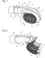
Figs. 1 and 2 , theturbine housing 1 made of sheet material mainly includes, but not limited to, ascroll part 3, acenter core part 9 and theoutlet pipe part 23. Further, thescroll part 3 includes, but not limited to, afirst scroll part 5 and asecond scroll part 7, thescroll parts turbine casing 1. - The
scroll part 3 forming a spiral gas passage is configured by butt-joining thefirst scroll part 5 and thesecond scroll part 7 as well as by weld-bonding the butt-joined parts. Thus, the gas passage is formed. As shown inFig. 3 , at the location of the A-A cross section, each of thescroll parts - At a circular center part of the
scroll part 3, thecenter core part 9 is provided, thecenter core part 9 as a whole almost forming a cylindrical shape. And, thecenter core part 9 includes, but not limited to: a bearinghousing part 15 in which a bearing supporting a rotation shaft of the turbine rotor 13 (cf.Figs. 5 and6 ) is arranged; and, a flowpassage outlet part 17 which forms a gas passage on the discharged side. Between the bearinghousing part 15 and the flowpassage outlet part 17, a plurality ofcolumns 21 is provided. - The
columns 21 provide aflow passage 19 through which the gas streaming along the spiral direction in thescroll part 3 can smoothly stream toward the center side; further, in order to connect the bearinghousing part 15 to the flowpassage outlet part 17,multiple columns 21 are arranged at predetermined locations in a hoop direction around the turbine rotor with a distance between columns. Thus, bearinghousing part 15 and the flowpassage outlet part 17 are connected to each other via the columns, and integrated into one body. - Further, the
columns 21 may be evenly or unevenly spaced in the hoop direction. And, the cross section profile of thecolumn 21 almost forms a quadrilateral; however, the cross section profile may form a triangle so that the profile has a tapered surface along the gas flow direction in order to prevent the column from being of resistance against the gas flow as well as in order to make the gas flow stream toward the central side. Or, the cross section profile may form a streamlined profile, although the cutting processes in machining become complicated. - Further, the
columns 21 connect the bearinghousing part 15 to the flowpassage outlet part 17; and, thecolumns 21 is made of a material having strength and heat resistance properties so that a gap space distance between theturbine rotor 13 and thecenter core part 9 is maintained constant even when temperatures become high or external forces appear. - In addition, an
outlet pipe part 23 of a pipe shape is jointed to a tip end side of the flowpassage outlet part 17 by means of welding around all the circumference of the jointing part. - The
first scroll part 5 and thesecond scroll part 7 are formed with a thin plate (whose thickness is about 1 to 3 mm) of sheet metal material; and, butt-joining the end sides of theparts Fig. 3 , the tip end of thepart 5 is superposed on the tip end of thepart 7; and, a welding part 'a' is formed. Along the welding part 'a,' a one-side fillet welding is performed from outside along the superposed part, namely along the whole circumference in the spiral direction of thescroll part 3. - In addition, instead of the one-side fillet welding, both the scroll parts may be welded by butt-welding in a manner that tip end sides of sheet metal members are butted and welding is performed along the butted part. Further, the sheet metal may be configured with a heat-resisting steel such as an austenite steel and a stainless steel.
- Further, the end part (of the first scroll part 5) on the
center core 9 side of thefirst scroll part 5 is weld-bonded to the bearinghousing part 15 along the outer circumference of the bearinghousing part 15; and, the end part (of the second scroll part 7) on thecenter core 9 side of thesecond scroll part 7 is weld-bonded to the bearinghousing part 15 along the outer circumference of the flowpassage outlet part 17. A welding part 'b' is formed along the outer circumference of the flowpassage outlet part 17. And, a welding part 'c' is formed along the outer circumference of the bearinghousing part 15. - Further, the bearing
housing part 15, the flowpassage outlet part 17 and thecolumns 21 connecting theparts housing part 15, the flowpassage outlet part 17 and thecolumns 21 is manufactured via cutting processes of machining of metals. Similarly, theoutlet pipe part 23 is manufactured via cutting processes of machining of metals. - The exhaust gas enters from an inlet pipe part 25 (cf.
Figs. 1 and 2 ), streams and circulates along a gas flow passage in thescroll part 3 toward a gas inlet part of thescroll part 3, and joins the exhaust gas entering the gas inlet part. The neighborhood area of atongue part 27 which configures a winding end part of thescroll part 3 is steeply heated up. When thetongue part 27 is steeply heated up, a force constraining a thermal elongation is generated by the temperature difference between thetongue part 27 and the neighborhood area. Hence, thermal compression-stresses are generated. And, the repeated thermal stresses cause cracks which is attributable to the thermal stresses. - The occurrence of the cracks attributable to the thermal stresses in the neighborhood of the
tongue part 27 is not limited to the turbine housing of the sheet metal structure according to the present invention. The cracks occur also in a case of the conventional turbine housing of a casting type. This has been confirmed by numerical analyses, experiments and the like. - In order to prevent the occurrence of the cracks due to the thermal stresses in the neighborhood of the
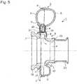
tongue part 27, in the present invention, awall part member 31 is provided on both sides of the welding part 'a', as shown inFig. 5 . - In other words, the
wall part member 31 is formed between an outer wall of the winding end part of thescroll part 3 and an outer wall of thefirst scroll part 5 extending from the gas flow inlet part to thetongue part 27; similarly, thewall part member 31 is formed between an outer wall of the winding end part of thescroll part 3 and an outer wall of thesecond scroll part 7 extending from the gas flow inlet part to thetongue part 27. Further, an upper end of the wall part member 31 (on the first scroll part side) is weld-bonded to the outer wall of thefirst scroll part 5; and, an upper end of the wall part member 31 (on the second scroll part side) is weld-bonded to the outer wall of thesecond scroll part 7. And, a lower end of the wall part member 31 (on the first scroll part side) is weld-bonded to the outer wall of the winding end part of thescroll part 3; and, a lower end of the wall part member 31 (on the second scroll part side) is weld-bonded to the outer wall of the winding end part of thescroll part 3. Further, the front ends of both thewall part members first scroll part 5 and thesecond scroll part 7 is enclosed and anenclosed space 33 is formed. - The range in which the
wall part members 31 are provided is formed in the neighborhood of a tongue part area as described by the area X inFig. 4 . This neighborhood of tongue part is an area of a hollow shape which is formed between the outer wall of the winding end part of thescroll 3 and the outer walls of thefirst scroll part 5 and thesecond scroll part 7, the outer walls of the first and second scroll parts extending from the gas flow inlet part to thetongue part 27. Thetongue part 27 is formed inside of thefirst scroll part 5 and thesecond scroll part 7, each of thescroll parts Fig.4 ). - In this way, by use of the
wall part members 31, a double-wall structure can be easily arranged in a certain limited area as a tongue part neighborhood area X where there is a concern about the risk of crack penetration. - Further, the butt-joined part of the
first scroll part 5 and thesecond scroll part 7 may be only superposed without performing welding, the butt-joined part of theparts wall part members 31 on both the sides. When the butt-joined part inside of the enclosedspace 33 which is enclosed by thewall part members 31 is welded along the whole circumference in the circulating direction of thescroll part 3, the sealing effect against exhaust gas leakage is enhanced although the strength reduction is brought by the thermal stress which welding accompanies. When the butt-joined part inside of the enclosedspace 33 which is enclosed by thewall part members 31 is not welded, the thermal stress which welding accompanies is not generated. Consequently, the strength reduction is prevented; further, the sealing function against the exhaust gas leakage is achieved by thewall part members 31 provide outside of the butt-joined part. - According to the present invention as described above, by forming a double-wall structure provided with: a wall structure which is formed by butt-joining the
first scroll part 5 and thesecond scroll part 7; and a wall structure which is formed by thewall part members 31 outside of the butt-joined part, thefirst scroll part 5 and thesecond scroll part 7 which are arranged along the internal flow as well as on the inner side can bear the thermal stresses. And, even if cracks or penetration appears, the internal gas leakage can be prevented by thewall part members 31 which withstand the internal gas pressure. - As a result, the occurrence of cracks such as causes the gas leakage in the neighborhood of the
tongue part 27 of theturbine housing 1 made of sheet metal can be prevented. Thus, the safety and reliability of the turbine housing made of sheet metal can be enhanced. - In the next place, based on
Figs. 6 and7 , a second mode of the present invention is now explained.Fig. 6 corresponds toFig. 5 . And,Fig. 6 shows the whole cross section along the D-D line cut ofFig. 4 . In the area X in the neighborhood of the tongue part, a line of the welding part 'a' along which the butt-joined part of thefirst scroll part 5 and thesecond scroll part 7 is welded is provided so that the line of the welding part 'a' departs from and detours around a location where thetongue part 27 is formed in the turbine rotation axis direction. The line of the welding part 'a' on the outer circumference side of thescroll part 3 is shifted to the location a1; the line of the welding part 'a' on the tongue side is shifted to the location a2. In this way, the lines of welding parts are provided. - Further, at a tongue part forming area Y where the
tongue part 27 is formed, the facing part of thefirst scroll part 5 and thesecond scroll part 7 does not exist; and the welding part 'a' is shifted toward the outside of the tongue part forming area Y (outside in the turbine rotation axis direction). By the configuration as described, only the member of thefirst scroll part 5 exists in the tongue part forming area Y. - Incidentally, as shown in
Figs. 5 and6 , the tongue part forming area Y is an area where a gas flow passage in a radial direction is formed from thescroll part 3 to theturbine rotor 3. - In
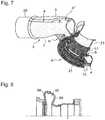
Fig. 7 , the major configuration of the second mode is shown in a bird view which corresponds to the bird view ofFig.2 . And,Fig. 7 shows the situation in which the line of the welding part 'a' of thescroll part 3 in the tongue part forming area X is shifted to the location a1. As is the case with the change of the location of the welding part 'a' into the location a1, the location of the welding part 'a' on the tongue part side is changed into the location a2 (not shown). - The possibility of the occurrence of cracks in the facing and weld-bonding part of the
first scroll part 5 and thesecond scroll part 7 is high, the cracks being caused by the thermal fatigue attributable to high thermal stresses due to welding. According to the second mode, the welding-joint line is shifted apart from a location where the tongue part is formed; and, in the area of thetongue part 27, only one of thefirst scroll part 5 and thesecond scroll part 7 exist, thescroll parts - Consequently, the risk of crack occurrence and the like due to thermal stresses and thermal fatigue in the
tongue part 27 as well as in the neighborhood of the tongue part can be avoided. Hence, the safety and reliability of the turbine housing made of sheet metal can be enhanced. - According to the present invention, the turbine housing structure made of sheet metal can be provided, wherein the crack occurrence and the like due to the thermal fatigue caused by rapid heating repetitions in the area of the tongue part as the scroll winding end part is prevented; and, the weight reduction can be achieved and the durability of the tongue part can be enhanced. Thus, the present invention is suitably applicable to a turbine housing made of sheet metal.
Claims (4)
- A turbine housing (1) for an exhaust gas turbocharger, the turbine housing (1) being made of sheet metal in which
a scroll part (3) forming a spiral exhaust gas passage is configured with scroll part members (5, 7), each having a facing part, at which the scroll part members are faced to and bonded to each other, the turbine housing (1) comprising a wall part member (31) which is provided on each side of a facing part of the scroll part members (5, 7), in a neighborhood area of a tongue part (27) configuring a winding end part of the scroll part (3),
wherein
the wall part members (31) which enclose the facing part and form a gas-tight space configure a double-wall structure;characterized in that one respective wall part member (31) is arranged on each side of the facing part of the scroll part members (5, 7) so that the wall part members (31) connect an outer wall surface of the scroll part (3) to an outer wall surface of a flow inlet part of the exhaust gas. - The turbine housing (1) made of sheet metal according to claim 1,
wherein
both the scroll part members (5, 7) facing each other are integrated into one body by weld-bonding the scroll part members (5, 7) along the whole circumference in the spiral direction of the scroll part (3). - The turbine housing made of sheet metal according to claim 1,
wherein
the facing part of both the scroll part members (5, 7) that is located inside of the space between the wall part members (31) is not weld-bonded the other facing part of both the scroll part members (5, 7) is integrated into one-body by weld-bonding the other facing part along the whole circumference in the spiral direction of the scroll part (3). - A turbine housing (1) for an exhaust gas turbocharger, the turbine housing (1) having a turbine rotation axis and being made of sheet metal in which a scroll part (3) forming a spiral exhaust gas passage is configured with scroll part members (5, 7) which face each other and are butt-jointed together,
wherein:the scroll part (3) is formed so that both the scroll part members (5, 7) are integrated into one body by weld-bonding the scroll part members (5, 7) along the whole circumference in the spiral direction of the scroll part (3) forming a welding-joint line;characterized in that in the neighbourhood of a tongue part (27) forming a winding-end part of the scroll part (3), the welding-joint line departs from an area where the tongue part (27) is located in the turbine rotation axis direction, such thatthe tongue part (27) is formed only with one of the scroll part members (7).
Applications Claiming Priority (1)
| Application Number | Priority Date | Filing Date | Title |
|---|---|---|---|
| PCT/JP2011/052104WO2012105004A1 (en) | 2011-02-02 | 2011-02-02 | Sheet metal turbine housing |
Publications (3)
| Publication Number | Publication Date |
|---|---|
| EP2508731A1 EP2508731A1 (en) | 2012-10-10 |
| EP2508731A4 EP2508731A4 (en) | 2018-03-07 |
| EP2508731B1true EP2508731B1 (en) | 2019-05-08 |
Family
ID=46602246
Family Applications (1)
| Application Number | Title | Priority Date | Filing Date |
|---|---|---|---|
| EP11805365.1AActiveEP2508731B1 (en) | 2011-02-02 | 2011-02-02 | Sheet metal turbine housing |
Country Status (5)
| Country | Link |
|---|---|
| US (1) | US9255485B2 (en) |
| EP (1) | EP2508731B1 (en) |
| KR (1) | KR101263613B1 (en) |
| CN (1) | CN102753799B (en) |
| WO (1) | WO2012105004A1 (en) |
Families Citing this family (18)
| Publication number | Priority date | Publication date | Assignee | Title |
|---|---|---|---|---|
| DE102010005761A1 (en)* | 2010-01-25 | 2011-07-28 | Benteler Automobiltechnik GmbH, 33102 | exhaust assembly |
| DE102012209562B4 (en)* | 2012-06-06 | 2017-08-31 | Continental Automotive Gmbh | Turbine housing for an exhaust gas turbocharger |
| US9828913B2 (en) | 2013-08-16 | 2017-11-28 | Wescast Industries, Inc. | Turbine housing |
| CN105793537B (en)* | 2013-12-27 | 2018-07-31 | 三菱重工发动机和增压器株式会社 | Turbine housing |
| JP2015140748A (en)* | 2014-01-29 | 2015-08-03 | 株式会社三五 | turbine housing |
| NL1040828B1 (en)* | 2014-06-02 | 2016-05-12 | Mitsubishi Turbocharger And Engine Europe B V | A spiral turbine casing of a turbocharger. |
| US9945258B2 (en) | 2014-10-10 | 2018-04-17 | Ford Global Technologies, Llc | Sheet metal turbine housing with cellular structure reinforcement |
| US10823061B2 (en)* | 2016-07-15 | 2020-11-03 | General Electric Company | Engine air inlet having a double-panel heated wall |
| US10472988B2 (en) | 2017-01-30 | 2019-11-12 | Garrett Transportation I Inc. | Sheet metal turbine housing and related turbocharger systems |
| US10494955B2 (en) | 2017-01-30 | 2019-12-03 | Garrett Transportation I Inc. | Sheet metal turbine housing with containment dampers |
| US10544703B2 (en) | 2017-01-30 | 2020-01-28 | Garrett Transportation I Inc. | Sheet metal turbine housing with cast core |
| US10436069B2 (en)* | 2017-01-30 | 2019-10-08 | Garrett Transportation I Inc. | Sheet metal turbine housing with biaxial volute configuration |
| US10690144B2 (en)* | 2017-06-27 | 2020-06-23 | Garrett Transportation I Inc. | Compressor housings and fabrication methods |
| US10662904B2 (en) | 2018-03-30 | 2020-05-26 | Deere & Company | Exhaust manifold |
| US11073076B2 (en) | 2018-03-30 | 2021-07-27 | Deere & Company | Exhaust manifold |
| JP7099625B2 (en)* | 2019-04-17 | 2022-07-12 | 株式会社Ihi | Turbine housing and turbocharger |
| CN213743545U (en)* | 2019-10-14 | 2021-07-20 | 博格华纳公司 | Turbocharger and turbine housing for a turbocharger |
| US11732729B2 (en)* | 2021-01-26 | 2023-08-22 | Garrett Transportation I Inc | Sheet metal turbine housing |
Family Cites Families (21)
| Publication number | Priority date | Publication date | Assignee | Title |
|---|---|---|---|---|
| JPS6290944U (en)* | 1985-11-28 | 1987-06-10 | ||
| DE29909018U1 (en)* | 1999-05-26 | 2000-09-28 | Heinrich Gillet GmbH & Co. KG, 67480 Edenkoben | Turbine housing for exhaust gas turbochargers |
| US7074009B2 (en)* | 2000-06-07 | 2006-07-11 | Borgwarner, Inc. | Casing assembly for the turbine of an exhaust turbochanger |
| DE10028160C2 (en) | 2000-06-07 | 2003-03-27 | Borgwarner Inc | Housing group for the turbine of an exhaust gas turbocharger |
| JP2002194525A (en) | 2000-12-27 | 2002-07-10 | Ishikawajima Harima Heavy Ind Co Ltd | Twin flow type turbine housing having wear resistance and wear resistant thermal spraying method of the twin flow type turbine housing |
| JP2002349276A (en) | 2001-05-25 | 2002-12-04 | Aisin Takaoka Ltd | Turbine housing |
| JP2003293779A (en) | 2002-03-29 | 2003-10-15 | Toyota Motor Corp | Turbine housing |
| EP1398465B1 (en) | 2002-09-10 | 2005-05-18 | BorgWarner Inc. | Turbocharger with rotor casing |
| JP4242212B2 (en)* | 2003-06-23 | 2009-03-25 | 株式会社小松製作所 | Turbocharger |
| DE102004039477B4 (en)* | 2004-08-14 | 2015-01-08 | Ihi Charging Systems International Gmbh | Turbine housing for an exhaust gas turbocharger |
| JP4485334B2 (en)* | 2004-12-02 | 2010-06-23 | トヨタ自動車株式会社 | Turbocharger turbine housing |
| JP2006161573A (en) | 2004-12-02 | 2006-06-22 | Toyota Motor Corp | Turbocharger turbine housing |
| JP4234107B2 (en) | 2005-02-10 | 2009-03-04 | 三菱重工業株式会社 | Variable displacement exhaust turbocharger and variable nozzle mechanism component manufacturing method |
| JP4448064B2 (en) | 2005-06-24 | 2010-04-07 | トヨタ自動車株式会社 | Turbine housing |
| JP4468286B2 (en) | 2005-10-21 | 2010-05-26 | 三菱重工業株式会社 | Exhaust turbocharger |
| JP4512058B2 (en) | 2006-04-04 | 2010-07-28 | トヨタ自動車株式会社 | Turbine housing |
| GB0614392D0 (en) | 2006-07-20 | 2006-08-30 | Cummins Turbo Tech Ltd | Turbine Housing for a turbocharger |
| JP4835330B2 (en) | 2006-08-31 | 2011-12-14 | トヨタ自動車株式会社 | Turbine housing |
| JP4875009B2 (en) | 2008-02-26 | 2012-02-15 | トヨタ自動車株式会社 | Turbine housing |
| JP5260082B2 (en) | 2008-02-26 | 2013-08-14 | 三菱重工業株式会社 | Turbocharger exhaust bypass valve |
| JP2010168969A (en)* | 2009-01-21 | 2010-08-05 | Toyota Motor Corp | Turbine housing |
- 2011
- 2011-02-02USUS13/384,958patent/US9255485B2/enactiveActive
- 2011-02-02WOPCT/JP2011/052104patent/WO2012105004A1/enactiveApplication Filing
- 2011-02-02CNCN201180002462.1Apatent/CN102753799B/ennot_activeExpired - Fee Related
- 2011-02-02KRKR1020117031148Apatent/KR101263613B1/ennot_activeExpired - Fee Related
- 2011-02-02EPEP11805365.1Apatent/EP2508731B1/enactiveActive
Also Published As
| Publication number | Publication date |
|---|---|
| CN102753799A (en) | 2012-10-24 |
| CN102753799B (en) | 2014-11-05 |
| WO2012105004A1 (en) | 2012-08-09 |
| KR20120107428A (en) | 2012-10-02 |
| EP2508731A4 (en) | 2018-03-07 |
| KR101263613B1 (en) | 2013-05-10 |
| EP2508731A1 (en) | 2012-10-10 |
| US20120251315A1 (en) | 2012-10-04 |
| US9255485B2 (en) | 2016-02-09 |
Similar Documents
| Publication | Publication Date | Title |
|---|---|---|
| EP2508731B1 (en) | Sheet metal turbine housing | |
| JP6126246B2 (en) | Turbine housing | |
| JP5338991B1 (en) | Turbine housing and exhaust turbine supercharger | |
| US8740557B2 (en) | Fabricated static vane ring | |
| WO2012077711A1 (en) | Sheet metal turbine housing | |
| US8469661B2 (en) | Fabricated gas turbine vane ring | |
| US8915707B2 (en) | Exhaust gas housing for a gas turbine and method for producing same | |
| EP3267010B1 (en) | Turbocharger | |
| EP3260670B1 (en) | Turbine housing | |
| US10240485B2 (en) | Turbine housing for an exhaust gas turbocharger | |
| WO2012090724A1 (en) | Turbine scroll structure | |
| US20110318177A1 (en) | Turbine housing for an exhaust gas turbocharger and method for producing turbine housing | |
| EP3354856B1 (en) | Turbine housing assembly | |
| EP2524128B1 (en) | Wheel housing for a turbocharger | |
| CN105781634B (en) | Turbine shroud for exhaust-driven turbo-charger exhaust-gas turbo charger | |
| JP5342427B2 (en) | Sheet metal turbine housing | |
| JP5518232B2 (en) | Sheet metal turbine housing | |
| US10704420B2 (en) | Turbine housing | |
| JP6756008B2 (en) | Turbocharger | |
| CN103967595B (en) | Sheet metal turbine shroud |
Legal Events
| Date | Code | Title | Description |
|---|---|---|---|
| PUAI | Public reference made under article 153(3) epc to a published international application that has entered the european phase | Free format text:ORIGINAL CODE: 0009012 | |
| 17P | Request for examination filed | Effective date:20120118 | |
| AK | Designated contracting states | Kind code of ref document:A1 Designated state(s):AL AT BE BG CH CY CZ DE DK EE ES FI FR GB GR HR HU IE IS IT LI LT LU LV MC MK MT NL NO PL PT RO RS SE SI SK SM TR | |
| R17P | Request for examination filed (corrected) | Effective date:20120118 | |
| DAX | Request for extension of the european patent (deleted) | ||
| REG | Reference to a national code | Ref country code:DE Ref legal event code:R079 Ref document number:602011058831 Country of ref document:DE Free format text:PREVIOUS MAIN CLASS: F02B0039000000 Ipc:F01D0009020000 | |
| RA4 | Supplementary search report drawn up and despatched (corrected) | Effective date:20180202 | |
| RIC1 | Information provided on ipc code assigned before grant | Ipc:F01D 9/02 20060101AFI20180129BHEP Ipc:F02C 6/12 20060101ALI20180129BHEP | |
| GRAP | Despatch of communication of intention to grant a patent | Free format text:ORIGINAL CODE: EPIDOSNIGR1 | |
| STAA | Information on the status of an ep patent application or granted ep patent | Free format text:STATUS: GRANT OF PATENT IS INTENDED | |
| INTG | Intention to grant announced | Effective date:20190218 | |
| GRAS | Grant fee paid | Free format text:ORIGINAL CODE: EPIDOSNIGR3 | |
| GRAA | (expected) grant | Free format text:ORIGINAL CODE: 0009210 | |
| STAA | Information on the status of an ep patent application or granted ep patent | Free format text:STATUS: THE PATENT HAS BEEN GRANTED | |
| AK | Designated contracting states | Kind code of ref document:B1 Designated state(s):AL AT BE BG CH CY CZ DE DK EE ES FI FR GB GR HR HU IE IS IT LI LT LU LV MC MK MT NL NO PL PT RO RS SE SI SK SM TR | |
| REG | Reference to a national code | Ref country code:GB Ref legal event code:FG4D | |
| REG | Reference to a national code | Ref country code:CH Ref legal event code:EP Ref country code:AT Ref legal event code:REF Ref document number:1130413 Country of ref document:AT Kind code of ref document:T Effective date:20190515 | |
| REG | Reference to a national code | Ref country code:DE Ref legal event code:R096 Ref document number:602011058831 Country of ref document:DE Ref country code:IE Ref legal event code:FG4D | |
| REG | Reference to a national code | Ref country code:NL Ref legal event code:FP | |
| REG | Reference to a national code | Ref country code:LT Ref legal event code:MG4D | |
| PG25 | Lapsed in a contracting state [announced via postgrant information from national office to epo] | Ref country code:AL Free format text:LAPSE BECAUSE OF FAILURE TO SUBMIT A TRANSLATION OF THE DESCRIPTION OR TO PAY THE FEE WITHIN THE PRESCRIBED TIME-LIMIT Effective date:20190508 Ref country code:NO Free format text:LAPSE BECAUSE OF FAILURE TO SUBMIT A TRANSLATION OF THE DESCRIPTION OR TO PAY THE FEE WITHIN THE PRESCRIBED TIME-LIMIT Effective date:20190808 Ref country code:PT Free format text:LAPSE BECAUSE OF FAILURE TO SUBMIT A TRANSLATION OF THE DESCRIPTION OR TO PAY THE FEE WITHIN THE PRESCRIBED TIME-LIMIT Effective date:20190908 Ref country code:FI Free format text:LAPSE BECAUSE OF FAILURE TO SUBMIT A TRANSLATION OF THE DESCRIPTION OR TO PAY THE FEE WITHIN THE PRESCRIBED TIME-LIMIT Effective date:20190508 Ref country code:SE Free format text:LAPSE BECAUSE OF FAILURE TO SUBMIT A TRANSLATION OF THE DESCRIPTION OR TO PAY THE FEE WITHIN THE PRESCRIBED TIME-LIMIT Effective date:20190508 Ref country code:HR Free format text:LAPSE BECAUSE OF FAILURE TO SUBMIT A TRANSLATION OF THE DESCRIPTION OR TO PAY THE FEE WITHIN THE PRESCRIBED TIME-LIMIT Effective date:20190508 Ref country code:ES Free format text:LAPSE BECAUSE OF FAILURE TO SUBMIT A TRANSLATION OF THE DESCRIPTION OR TO PAY THE FEE WITHIN THE PRESCRIBED TIME-LIMIT Effective date:20190508 Ref country code:LT Free format text:LAPSE BECAUSE OF FAILURE TO SUBMIT A TRANSLATION OF THE DESCRIPTION OR TO PAY THE FEE WITHIN THE PRESCRIBED TIME-LIMIT Effective date:20190508 | |
| PG25 | Lapsed in a contracting state [announced via postgrant information from national office to epo] | Ref country code:GR Free format text:LAPSE BECAUSE OF FAILURE TO SUBMIT A TRANSLATION OF THE DESCRIPTION OR TO PAY THE FEE WITHIN THE PRESCRIBED TIME-LIMIT Effective date:20190809 Ref country code:BG Free format text:LAPSE BECAUSE OF FAILURE TO SUBMIT A TRANSLATION OF THE DESCRIPTION OR TO PAY THE FEE WITHIN THE PRESCRIBED TIME-LIMIT Effective date:20190808 Ref country code:RS Free format text:LAPSE BECAUSE OF FAILURE TO SUBMIT A TRANSLATION OF THE DESCRIPTION OR TO PAY THE FEE WITHIN THE PRESCRIBED TIME-LIMIT Effective date:20190508 Ref country code:LV Free format text:LAPSE BECAUSE OF FAILURE TO SUBMIT A TRANSLATION OF THE DESCRIPTION OR TO PAY THE FEE WITHIN THE PRESCRIBED TIME-LIMIT Effective date:20190508 | |
| REG | Reference to a national code | Ref country code:AT Ref legal event code:MK05 Ref document number:1130413 Country of ref document:AT Kind code of ref document:T Effective date:20190508 | |
| PG25 | Lapsed in a contracting state [announced via postgrant information from national office to epo] | Ref country code:RO Free format text:LAPSE BECAUSE OF FAILURE TO SUBMIT A TRANSLATION OF THE DESCRIPTION OR TO PAY THE FEE WITHIN THE PRESCRIBED TIME-LIMIT Effective date:20190508 Ref country code:CZ Free format text:LAPSE BECAUSE OF FAILURE TO SUBMIT A TRANSLATION OF THE DESCRIPTION OR TO PAY THE FEE WITHIN THE PRESCRIBED TIME-LIMIT Effective date:20190508 Ref country code:EE Free format text:LAPSE BECAUSE OF FAILURE TO SUBMIT A TRANSLATION OF THE DESCRIPTION OR TO PAY THE FEE WITHIN THE PRESCRIBED TIME-LIMIT Effective date:20190508 Ref country code:AT Free format text:LAPSE BECAUSE OF FAILURE TO SUBMIT A TRANSLATION OF THE DESCRIPTION OR TO PAY THE FEE WITHIN THE PRESCRIBED TIME-LIMIT Effective date:20190508 Ref country code:DK Free format text:LAPSE BECAUSE OF FAILURE TO SUBMIT A TRANSLATION OF THE DESCRIPTION OR TO PAY THE FEE WITHIN THE PRESCRIBED TIME-LIMIT Effective date:20190508 Ref country code:SK Free format text:LAPSE BECAUSE OF FAILURE TO SUBMIT A TRANSLATION OF THE DESCRIPTION OR TO PAY THE FEE WITHIN THE PRESCRIBED TIME-LIMIT Effective date:20190508 | |
| REG | Reference to a national code | Ref country code:DE Ref legal event code:R097 Ref document number:602011058831 Country of ref document:DE | |
| PG25 | Lapsed in a contracting state [announced via postgrant information from national office to epo] | Ref country code:IT Free format text:LAPSE BECAUSE OF FAILURE TO SUBMIT A TRANSLATION OF THE DESCRIPTION OR TO PAY THE FEE WITHIN THE PRESCRIBED TIME-LIMIT Effective date:20190508 Ref country code:SM Free format text:LAPSE BECAUSE OF FAILURE TO SUBMIT A TRANSLATION OF THE DESCRIPTION OR TO PAY THE FEE WITHIN THE PRESCRIBED TIME-LIMIT Effective date:20190508 | |
| PLBE | No opposition filed within time limit | Free format text:ORIGINAL CODE: 0009261 | |
| STAA | Information on the status of an ep patent application or granted ep patent | Free format text:STATUS: NO OPPOSITION FILED WITHIN TIME LIMIT | |
| PG25 | Lapsed in a contracting state [announced via postgrant information from national office to epo] | Ref country code:TR Free format text:LAPSE BECAUSE OF FAILURE TO SUBMIT A TRANSLATION OF THE DESCRIPTION OR TO PAY THE FEE WITHIN THE PRESCRIBED TIME-LIMIT Effective date:20190508 | |
| 26N | No opposition filed | Effective date:20200211 | |
| PG25 | Lapsed in a contracting state [announced via postgrant information from national office to epo] | Ref country code:PL Free format text:LAPSE BECAUSE OF FAILURE TO SUBMIT A TRANSLATION OF THE DESCRIPTION OR TO PAY THE FEE WITHIN THE PRESCRIBED TIME-LIMIT Effective date:20190508 | |
| PG25 | Lapsed in a contracting state [announced via postgrant information from national office to epo] | Ref country code:SI Free format text:LAPSE BECAUSE OF FAILURE TO SUBMIT A TRANSLATION OF THE DESCRIPTION OR TO PAY THE FEE WITHIN THE PRESCRIBED TIME-LIMIT Effective date:20190508 | |
| REG | Reference to a national code | Ref country code:CH Ref legal event code:PL | |
| REG | Reference to a national code | Ref country code:BE Ref legal event code:MM Effective date:20200229 | |
| PG25 | Lapsed in a contracting state [announced via postgrant information from national office to epo] | Ref country code:LU Free format text:LAPSE BECAUSE OF NON-PAYMENT OF DUE FEES Effective date:20200202 Ref country code:MC Free format text:LAPSE BECAUSE OF FAILURE TO SUBMIT A TRANSLATION OF THE DESCRIPTION OR TO PAY THE FEE WITHIN THE PRESCRIBED TIME-LIMIT Effective date:20190508 | |
| PG25 | Lapsed in a contracting state [announced via postgrant information from national office to epo] | Ref country code:CH Free format text:LAPSE BECAUSE OF NON-PAYMENT OF DUE FEES Effective date:20200229 Ref country code:LI Free format text:LAPSE BECAUSE OF NON-PAYMENT OF DUE FEES Effective date:20200229 | |
| PG25 | Lapsed in a contracting state [announced via postgrant information from national office to epo] | Ref country code:IE Free format text:LAPSE BECAUSE OF NON-PAYMENT OF DUE FEES Effective date:20200202 | |
| PG25 | Lapsed in a contracting state [announced via postgrant information from national office to epo] | Ref country code:BE Free format text:LAPSE BECAUSE OF NON-PAYMENT OF DUE FEES Effective date:20200229 | |
| PG25 | Lapsed in a contracting state [announced via postgrant information from national office to epo] | Ref country code:MT Free format text:LAPSE BECAUSE OF FAILURE TO SUBMIT A TRANSLATION OF THE DESCRIPTION OR TO PAY THE FEE WITHIN THE PRESCRIBED TIME-LIMIT Effective date:20190508 Ref country code:CY Free format text:LAPSE BECAUSE OF FAILURE TO SUBMIT A TRANSLATION OF THE DESCRIPTION OR TO PAY THE FEE WITHIN THE PRESCRIBED TIME-LIMIT Effective date:20190508 | |
| PG25 | Lapsed in a contracting state [announced via postgrant information from national office to epo] | Ref country code:MK Free format text:LAPSE BECAUSE OF FAILURE TO SUBMIT A TRANSLATION OF THE DESCRIPTION OR TO PAY THE FEE WITHIN THE PRESCRIBED TIME-LIMIT Effective date:20190508 Ref country code:IS Free format text:LAPSE BECAUSE OF FAILURE TO SUBMIT A TRANSLATION OF THE DESCRIPTION OR TO PAY THE FEE WITHIN THE PRESCRIBED TIME-LIMIT Effective date:20190908 | |
| PGFP | Annual fee paid to national office [announced via postgrant information from national office to epo] | Ref country code:GB Payment date:20221230 Year of fee payment:13 | |
| PGFP | Annual fee paid to national office [announced via postgrant information from national office to epo] | Ref country code:FR Payment date:20230110 Year of fee payment:13 | |
| PGFP | Annual fee paid to national office [announced via postgrant information from national office to epo] | Ref country code:DE Payment date:20221229 Year of fee payment:13 | |
| PGFP | Annual fee paid to national office [announced via postgrant information from national office to epo] | Ref country code:NL Payment date:20230113 Year of fee payment:13 | |
| REG | Reference to a national code | Ref country code:DE Ref legal event code:R119 Ref document number:602011058831 Country of ref document:DE | |
| REG | Reference to a national code | Ref country code:NL Ref legal event code:MM Effective date:20240301 | |
| GBPC | Gb: european patent ceased through non-payment of renewal fee | Effective date:20240202 | |
| PG25 | Lapsed in a contracting state [announced via postgrant information from national office to epo] | Ref country code:NL Free format text:LAPSE BECAUSE OF NON-PAYMENT OF DUE FEES Effective date:20240301 | |
| PG25 | Lapsed in a contracting state [announced via postgrant information from national office to epo] | Ref country code:NL Free format text:LAPSE BECAUSE OF NON-PAYMENT OF DUE FEES Effective date:20240301 | |
| PG25 | Lapsed in a contracting state [announced via postgrant information from national office to epo] | Ref country code:DE Free format text:LAPSE BECAUSE OF NON-PAYMENT OF DUE FEES Effective date:20240903 | |
| PG25 | Lapsed in a contracting state [announced via postgrant information from national office to epo] | Ref country code:GB Free format text:LAPSE BECAUSE OF NON-PAYMENT OF DUE FEES Effective date:20240202 | |
| PG25 | Lapsed in a contracting state [announced via postgrant information from national office to epo] | Ref country code:FR Free format text:LAPSE BECAUSE OF NON-PAYMENT OF DUE FEES Effective date:20240229 | |
| PG25 | Lapsed in a contracting state [announced via postgrant information from national office to epo] | Ref country code:GB Free format text:LAPSE BECAUSE OF NON-PAYMENT OF DUE FEES Effective date:20240202 Ref country code:FR Free format text:LAPSE BECAUSE OF NON-PAYMENT OF DUE FEES Effective date:20240229 Ref country code:DE Free format text:LAPSE BECAUSE OF NON-PAYMENT OF DUE FEES Effective date:20240903 |