EP2508220B1 - Assisted breathing device - Google Patents
Assisted breathing deviceDownload PDFInfo
- Publication number
- EP2508220B1 EP2508220B1EP12160382.3AEP12160382AEP2508220B1EP 2508220 B1EP2508220 B1EP 2508220B1EP 12160382 AEP12160382 AEP 12160382AEP 2508220 B1EP2508220 B1EP 2508220B1
- Authority
- EP
- European Patent Office
- Prior art keywords
- tube
- patient
- main
- channel
- distal end
- Prior art date
- Legal status (The legal status is an assumption and is not a legal conclusion. Google has not performed a legal analysis and makes no representation as to the accuracy of the status listed.)
- Not-in-force
Links
- 230000029058respiratory gaseous exchangeEffects0.000titledescription16
- 230000000241respiratory effectEffects0.000claimsdescription22
- 239000011324beadSubstances0.000claimsdescription15
- 238000007789sealingMethods0.000claimsdescription15
- 210000003238esophagusAnatomy0.000claimsdescription14
- 239000012530fluidSubstances0.000claimsdescription14
- 210000003800pharynxAnatomy0.000claimsdescription14
- 210000003437tracheaAnatomy0.000claimsdescription13
- 210000002345respiratory systemAnatomy0.000claimsdescription9
- 230000002093peripheral effectEffects0.000claimsdescription3
- 230000006837decompressionEffects0.000description10
- 210000004072lungAnatomy0.000description7
- 230000006835compressionEffects0.000description5
- 238000007906compressionMethods0.000description5
- 208000010496Heart ArrestDiseases0.000description4
- 230000017531blood circulationEffects0.000description3
- 210000000038chestAnatomy0.000description3
- 230000002496gastric effectEffects0.000description3
- 230000007423decreaseEffects0.000description2
- 210000000867larynxAnatomy0.000description2
- 238000010992refluxMethods0.000description2
- 238000007664blowingMethods0.000description1
- 230000004087circulationEffects0.000description1
- 230000008034disappearanceEffects0.000description1
- 239000003814drugSubstances0.000description1
- 238000002347injectionMethods0.000description1
- 239000007924injectionSubstances0.000description1
- 239000000463materialSubstances0.000description1
- 229920000915polyvinyl chloridePolymers0.000description1
- 239000004800polyvinyl chlorideSubstances0.000description1
- 230000001737promoting effectEffects0.000description1
- 239000000523sampleSubstances0.000description1
- 239000004447silicone coatingSubstances0.000description1
- 230000002269spontaneous effectEffects0.000description1
- 210000002784stomachAnatomy0.000description1
- 210000000115thoracic cavityAnatomy0.000description1
- 238000009423ventilationMethods0.000description1
Images


Classifications
- A—HUMAN NECESSITIES
- A61—MEDICAL OR VETERINARY SCIENCE; HYGIENE
- A61M—DEVICES FOR INTRODUCING MEDIA INTO, OR ONTO, THE BODY; DEVICES FOR TRANSDUCING BODY MEDIA OR FOR TAKING MEDIA FROM THE BODY; DEVICES FOR PRODUCING OR ENDING SLEEP OR STUPOR
- A61M16/00—Devices for influencing the respiratory system of patients by gas treatment, e.g. ventilators; Tracheal tubes
- A61M16/10—Preparation of respiratory gases or vapours
- A61M16/12—Preparation of respiratory gases or vapours by mixing different gases
- A—HUMAN NECESSITIES
- A61—MEDICAL OR VETERINARY SCIENCE; HYGIENE
- A61M—DEVICES FOR INTRODUCING MEDIA INTO, OR ONTO, THE BODY; DEVICES FOR TRANSDUCING BODY MEDIA OR FOR TAKING MEDIA FROM THE BODY; DEVICES FOR PRODUCING OR ENDING SLEEP OR STUPOR
- A61M16/00—Devices for influencing the respiratory system of patients by gas treatment, e.g. ventilators; Tracheal tubes
- A61M16/04—Tracheal tubes
- A61M16/0402—Special features for tracheal tubes not otherwise provided for
- A61M16/0409—Special features for tracheal tubes not otherwise provided for with mean for closing the oesophagus
- A—HUMAN NECESSITIES
- A61—MEDICAL OR VETERINARY SCIENCE; HYGIENE
- A61M—DEVICES FOR INTRODUCING MEDIA INTO, OR ONTO, THE BODY; DEVICES FOR TRANSDUCING BODY MEDIA OR FOR TAKING MEDIA FROM THE BODY; DEVICES FOR PRODUCING OR ENDING SLEEP OR STUPOR
- A61M16/00—Devices for influencing the respiratory system of patients by gas treatment, e.g. ventilators; Tracheal tubes
- A61M16/04—Tracheal tubes
- A61M16/0402—Special features for tracheal tubes not otherwise provided for
- A61M16/0415—Special features for tracheal tubes not otherwise provided for with access means to the stomach
- A—HUMAN NECESSITIES
- A61—MEDICAL OR VETERINARY SCIENCE; HYGIENE
- A61M—DEVICES FOR INTRODUCING MEDIA INTO, OR ONTO, THE BODY; DEVICES FOR TRANSDUCING BODY MEDIA OR FOR TAKING MEDIA FROM THE BODY; DEVICES FOR PRODUCING OR ENDING SLEEP OR STUPOR
- A61M16/00—Devices for influencing the respiratory system of patients by gas treatment, e.g. ventilators; Tracheal tubes
- A61M16/04—Tracheal tubes
- A61M16/0434—Cuffs
- A61M16/0445—Special cuff forms, e.g. undulated
- A—HUMAN NECESSITIES
- A61—MEDICAL OR VETERINARY SCIENCE; HYGIENE
- A61M—DEVICES FOR INTRODUCING MEDIA INTO, OR ONTO, THE BODY; DEVICES FOR TRANSDUCING BODY MEDIA OR FOR TAKING MEDIA FROM THE BODY; DEVICES FOR PRODUCING OR ENDING SLEEP OR STUPOR
- A61M16/00—Devices for influencing the respiratory system of patients by gas treatment, e.g. ventilators; Tracheal tubes
- A61M16/04—Tracheal tubes
- A61M16/0434—Cuffs
- A61M16/0454—Redundant cuffs
- A61M16/0459—Redundant cuffs one cuff behind another
- A—HUMAN NECESSITIES
- A61—MEDICAL OR VETERINARY SCIENCE; HYGIENE
- A61M—DEVICES FOR INTRODUCING MEDIA INTO, OR ONTO, THE BODY; DEVICES FOR TRANSDUCING BODY MEDIA OR FOR TAKING MEDIA FROM THE BODY; DEVICES FOR PRODUCING OR ENDING SLEEP OR STUPOR
- A61M16/00—Devices for influencing the respiratory system of patients by gas treatment, e.g. ventilators; Tracheal tubes
- A61M16/04—Tracheal tubes
- A61M16/0475—Tracheal tubes having openings in the tube
- A61M16/0477—Tracheal tubes having openings in the tube with incorporated means for delivering or removing fluids
- A61M16/0484—Tracheal tubes having openings in the tube with incorporated means for delivering or removing fluids at the distal end
- A—HUMAN NECESSITIES
- A61—MEDICAL OR VETERINARY SCIENCE; HYGIENE
- A61M—DEVICES FOR INTRODUCING MEDIA INTO, OR ONTO, THE BODY; DEVICES FOR TRANSDUCING BODY MEDIA OR FOR TAKING MEDIA FROM THE BODY; DEVICES FOR PRODUCING OR ENDING SLEEP OR STUPOR
- A61M16/00—Devices for influencing the respiratory system of patients by gas treatment, e.g. ventilators; Tracheal tubes
- A61M16/08—Bellows; Connecting tubes ; Water traps; Patient circuits
- A61M16/0816—Joints or connectors
- A61M16/0841—Joints or connectors for sampling
- A61M16/085—Gas sampling
- A—HUMAN NECESSITIES
- A61—MEDICAL OR VETERINARY SCIENCE; HYGIENE
- A61M—DEVICES FOR INTRODUCING MEDIA INTO, OR ONTO, THE BODY; DEVICES FOR TRANSDUCING BODY MEDIA OR FOR TAKING MEDIA FROM THE BODY; DEVICES FOR PRODUCING OR ENDING SLEEP OR STUPOR
- A61M16/00—Devices for influencing the respiratory system of patients by gas treatment, e.g. ventilators; Tracheal tubes
- A61M16/08—Bellows; Connecting tubes ; Water traps; Patient circuits
- A61M16/0816—Joints or connectors
- A61M16/0841—Joints or connectors for sampling
- A61M16/0858—Pressure sampling ports
- A—HUMAN NECESSITIES
- A61—MEDICAL OR VETERINARY SCIENCE; HYGIENE
- A61M—DEVICES FOR INTRODUCING MEDIA INTO, OR ONTO, THE BODY; DEVICES FOR TRANSDUCING BODY MEDIA OR FOR TAKING MEDIA FROM THE BODY; DEVICES FOR PRODUCING OR ENDING SLEEP OR STUPOR
- A61M16/00—Devices for influencing the respiratory system of patients by gas treatment, e.g. ventilators; Tracheal tubes
- A61M16/10—Preparation of respiratory gases or vapours
- A61M16/12—Preparation of respiratory gases or vapours by mixing different gases
- A61M16/122—Preparation of respiratory gases or vapours by mixing different gases with dilution
- A61M16/125—Diluting primary gas with ambient air
- A61M16/127—Diluting primary gas with ambient air by Venturi effect, i.e. entrainment mixers
Definitions
- the present inventionrelates to a respiratory assistance device, which can advantageously be used as an artificial respiration device during the resuscitation of a person in a state of cardiac arrest.
- this device for spontaneous breathing patientcan be used successfully as a device for artificial respiration (and not only as a respiratory support device) on persons in cardiac arrest during resuscitation by alternating compressions and thoracic decompressions of their thoracic cage, the respiratory gas jets of the auxiliary channels continuously promoting the resumption of inspiration and blood circulation.
- said breathing gascontinuously introduced into the lungs of the person in a state of cardiac arrest, generates in them, at the end of compression and at the beginning of the following decompression, a pressure residual positive, which is maintained during part of said decompression, before disappearing and being replaced by a negative pressure generated by the decompression.
- a positive residual pressureforms an obstacle to the intake of outside air through said tubular element and, on the other hand, is maintained by said external air sucked.
- the lungs of said personsuck poorly outside air and blood circulation (including venous return) is not satisfactorily provided at the ends (head, arm, legs) of said person.
- the object of the present inventionis therefore to improve the known device, recalled above, by eliminating the aforementioned drawbacks.
- the secondary tubecauses a restriction of the main channel, which increases the resistance exerted on the gas flow through the main channel and generates, during a compression of the rib cage of a person being resuscitated, an increase in pressure (positive pressure) inside the lungs, the air expelled from the latter escaping more easily than in the absence of secondary tube.
- the pressuredecreases more (negative pressure) in the lungs than with a known artificial breathing device without a secondary tube.
- the braking of the outside air inlet, generated by the diameter restriction,allows a gradual and controlled aspiration of the outside air towards the lungs of the person, resulting in the disappearance, at the beginning of the decompression, the positive residual pressure due to the jets of respiratory gas.
- the positive residual pressuredisappears rapidly under the action of decompression, during the gradual entry of the outside air sucked.
- the positive residual pressureis no longer an obstacle to the aspiration of outside air and blood circulation of the person in a state of cardiac arrest.
- the variation in intrathoracic pressure between compression and decompressionis extended in comparison with the variations in intrathoracic pressure observed in persons undergoing resuscitation equipped with a known respiratory assistance device, for example of the type of that described by the patent application WO2009 / 077667 .
- the gas exchange surfaceis thus increased and the venous return improved.
- the secondary tubemakes it possible to evacuate gastric fluid, or else to empty the stomach if necessary, which, in the event of leakage of the sealing means, prevents rejection into the trachea or an obstruction of the main channel of the device.
- the respiratory assistance device of the inventioncan be removably connected to another medical device.
- the main and secondary tubesare preferably concentric over at least a portion of the length of said main tube.
- the secondary tubemay also be removably mounted with respect to said respiratory assistance device, so that it can be inserted and / or removed from the main channel according to the desired use.
- said sealing meansare shaped so as to ensure tight fluid communication between the esophagus of said patient and said secondary channel.
- said sealing meansare in the form of an inflatable bead carried by the periphery flared and truncated at an angle of a trumpet-shaped piece which is attached to the end. distal of the main tube.
- the sealing meansare advantageously in the form of two separate inflatable balloons of annular shape, one of which surrounds the distal end of the main tube and the other surrounds the tube principal such that said communication port is arranged between the two balloons.
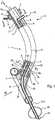
- the device 1comprises a main tube 4, flexible (or preformed to adapt to the morphology of the patient) delimiting a main channel 5 opening, through the orifice 6, to the proximal end 2 and through the orifice 7 at the distal end 3.
- the main channel 5is capable of ensuring the passage between the orifices 6 and 7, one of which (the distal orifice 7) is intended to be inside the respiratory tract of a patient, and the other (the proximal orifice 6) is intended to be outside said patient.
- This proximal orifice 6can open into the open air and, in this case, the patient can breathe in fresh air and exhale stale air through the main channel 5 (one could also connect the orifice 6 to a source of pressurized breathing gas and provide a system of unidirectional valves, so that the patient inhales the respiratory gas from said source through said main channel 5 and exhales stale air in the open air , also through this main channel).
- the diameter of the main channel 5is of the order of a few millimeters.
- auxiliary channels 8extending over almost the entire length of the main channel 5 and intended to be connected to a source of pressurized breathing gas, as described below.
- connection to the source of pressurized respiratory gascan be achieved by means of a ring 9, sealingly surrounding the tube 4, on the side of the proximal end 2, and delimiting a sealed annular chamber 10 around said tube.
- the auxiliary channels 8are placed in communication with the chamber 10, thanks to local tear-offs 11 of the wall of the tube 4, and said chamber 10 is connected to said source of breathing gas via a conduit 12.
- the proximal ends of the 8are closed, for example by plugs 13, introduced from the proximal end face of the tube 4.
- the auxiliary channels 8have a diameter smaller than that of the main channel 5.
- the diameter of the auxiliary channels 8is preferably less than 1 mm and, advantageously, it is of the order of 400 to 800 microns.
- the auxiliary channels 8open into a recess 14 of the inner wall 15 of the tube 4.
- the recess 14is annular and centered on the axis 16 of the distal end 3. It comprises a face 14a, substantially transverse or slightly inclined so as to constitute a flare of the main channel 5, into which said auxiliary channels 8 open through their orifices 17, and a face 14b along the face 14a and converging towards the axis 16.
- auxiliary channels 8are supplied with pressurized breathing gas through the elements 9 to 1 2, the corresponding gaseous jets strike the inclined face 14b, which deflects them in the direction of the axis 16 (see the arrow on the figure 1 at the outlet of the orifices 17), generating inside the distal end 3 of the main channel 5 an oblong shaped pressure zone originating at said distal orifices 17 and extending towards the distal orifice 7 along of the axis 16 of said distal end 3.
- the cross section of this pressure zonedecreases progressively from the recess 14 towards the distal orifice 7, said pressure zone progressively diverging from the inner wall 15 of the tube 4 to occupy only the central part of the distal end 3 of the latter.
- the jets of deflated respiratory gasDownstream of the pressure zone, the jets of deflated respiratory gas generate, in the vicinity of the axis 16, a depression zone favoring gas circulation inside the main channel 5, from the proximal orifice to the distal orifice. This encourages the patient's inspiration.
- auxiliary channels 8are arranged regularly around the axis of the tube 4. Their number varies according to the uses (adult or child), but it is generally between three and nine.
- the tube 4 of the device according to the inventioncan be made of any material already used in respiratory probes, for example a polyvinyl chloride, with a possible silicone coating.
- Additional channels 20are provided in the thickness of said tube 4. These channels 20 may be used for different purposes, such as injecting a fluid medicine, taking pressure, collecting gaseous samples (as indicated symbolically by the arrow f lying next to a channel 20 at the bottom of the figure 1 ) and, as will be described below, inflation of sealing bead.
- channel 8 and channel portions 20have been shown, although these channels are located in different planes (see FIGS. Figures 2 and 3 ).
- annularly shaped inflatable bead 21carried on the periphery 22 of a part 23.
- the part 23has the at least approximate shape of a trumpet and is nested by its small end on the distal end 3 of the tube 4.
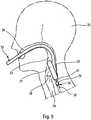
- the flared end of the part 23is truncated obliquely, so that said periphery 22 and the inflatable bead 21 that it carries, are inclined with respect to the axis In this way, when the device 1 is introduced in the deflated state into a patient 25, through the mouth 26 and the pharynx 27 thereof, the bead 21 is capable, after inflation.
- the bead 21partially closes the esophagus 30 by its shaped portion 21 A.
- the device 1also comprises a flexible secondary tube 31, forming a secondary channel 32, which extends inside the main tube 4, over almost all of its length.
- the proximal end 33is intended to be disposed outside the mouth of the patient, while the distal end 34 is, for its part, intended to be connected to the patient's esophagus as shown in FIG. figure 5 .
- the main and secondary tubes 4 and 31are concentric, the main channel 5 having an internal diameter substantially greater than the external diameter of the secondary tube 31.
- the secondary tube 31passes through the inflatable bead 21 and extends outside thereof.
- the portion 31A of the tube 31, which extends beyond the bead 21,comprises an annular auxiliary inflatable balloon 35, which surrounds it. The latter ensures, once properly positioned and inflated, tight fluidic communication between the patient's esophagus 30 and the secondary channel 32.
- An additional channel(not shown in the figures) is provided in the thickness of the secondary tube 31 and opens into the auxiliary balloon 35 to allow the injection of an inflation gas therein.
- any gastric flow in the trachea or in the pharynxis avoided in the event of a leakage of the bead. 21, the tube 31 for evacuation of said flow.
- the main tube 4extends, at its distal end 3, beyond the recess 14 by a tubular portion 31B, centered on the axis 16, whose side walls converge in the direction of the axis 16 and are secured to the outer side wall of the secondary tube 31, at its distal end.
- the distal end 7 of the main channel 5is sealed, only the distal end 34 of the secondary channel 32 being open to allow fluid communication between the esophagus 30 and the channel 32.
- through communication orifices 36are formed in the side wall of the main tube 4, downstream of the recess 14, to allow fluid communication, at the level of the patient's pharynx 27, between the trachea 29 thereof. and the main channel 5.
- a first inflatable balloon 37surrounds the side wall of the main tube 4, at its distal end. This balloon 37 is intended to be introduced into the patient's esophagus 30 to ensure tight fluidic communication between said esophagus 30 and the secondary channel 32.
- a second inflatable balloon 38also of annular shape, surrounds the side wall of the main tube 4 so that the communication orifices 36 are all interposed between the two balloons 37 and 38.
- a sealed fluid communicationat the level of pharynx 27 of the patient, can be obtained between the trachea 29 thereof and the main channel 5, once the two balloons 37 and 38 inflated.
- the balloons 37 and 38 in positionare inflated by an inflation gas G supplied from a source (not shown) to the device 1, then transmitted to said balloons 37 and 38 through feed channels 20 (partially shown).
Landscapes
- Health & Medical Sciences (AREA)
- Pulmonology (AREA)
- Heart & Thoracic Surgery (AREA)
- Engineering & Computer Science (AREA)
- Anesthesiology (AREA)
- Biomedical Technology (AREA)
- Emergency Medicine (AREA)
- Hematology (AREA)
- Life Sciences & Earth Sciences (AREA)
- Animal Behavior & Ethology (AREA)
- General Health & Medical Sciences (AREA)
- Public Health (AREA)
- Veterinary Medicine (AREA)
- Media Introduction/Drainage Providing Device (AREA)
Description
Translated fromFrenchLa présente invention concerne un dispositif d'assistance respiratoire, apte à être avantageusement utilisé comme dispositif de respiration artificielle pendant la réanimation d'une personne en état d'arrêt cardiaque.The present invention relates to a respiratory assistance device, which can advantageously be used as an artificial respiration device during the resuscitation of a person in a state of cardiac arrest.
Notamment par la demande de brevet
- un tube qui forme un canal principal et qui est destiné à être relié, par son extrémité distale, à une voie respiratoire d'un patient pour que ledit canal principal relie à l'extérieur le système respiratoire de celui-ci ;
- des canaux auxiliaires périphériques reliés à une source de gaz respiratoire, pour pouvoir insuffler du gaz respiratoire dans le système respiratoire du patient, et qui débouchent, par leur extrémité distale, dans le canal principal ;
- des moyens pour défléchir, vers l'intérieur dudit canal principal, le gaz respiratoire injecté par les canaux auxiliaires ; et
- des moyens d'étanchéité, entourant ledit tube, aptes à assurer, au niveau du pharynx du patient, une communication fluidique étanche entre la trachée du patient et le canal principal.
- a tube which forms a main channel and which is intended to be connected, at its distal end, to a respiratory tract of a patient so that said main channel connects the respiratory system thereof to the outside;
- peripheral auxiliary channels connected to a source of breathing gas, for blowing respiratory gas into the respiratory system of the patient, and which, through their distal end, open into the main channel;
- means for deflecting, inwardly of said main channel, the respiratory gas injected through the auxiliary channels; and
- sealing means, surrounding said tube, adapted to ensure, at the pharynx of the patient, a sealed fluid communication between the trachea of the patient and the main channel.
Ainsi, pour obtenir une ventilation en gaz respiratoire satisfaisante d'un patient, il suffit d'introduire l'extrémité distale du dispositif précité jusqu'au pharynx de celui (et non jusqu'à la carène à travers le larynx et la trachée) pour assurer l'assistance respiratoire désirée.Thus, to obtain satisfactory respiratory gas ventilation of a patient, it is sufficient to introduce the distal end of the aforementioned device to the pharynx of that (and not to the carina through the larynx and the trachea) to provide the desired respiratory support.
Par ailleurs, l'expérience a montré que ce dispositif pour patient à respiration spontanée peut être utilisé avec succès comme dispositif de respiration artificielle (et non plus seulement comme dispositif d'assistance respiratoire) sur des personnes en état d'arrêt cardiaque en cours de réanimation par compressions et décompressions thoraciques alternées de leur cage thoracique, les jets de gaz respiratoire des canaux auxiliaires en continu favorisant la reprise de l'inspiration et de la circulation sanguine.Moreover, experience has shown that this device for spontaneous breathing patient can be used successfully as a device for artificial respiration (and not only as a respiratory support device) on persons in cardiac arrest during resuscitation by alternating compressions and thoracic decompressions of their thoracic cage, the respiratory gas jets of the auxiliary channels continuously promoting the resumption of inspiration and blood circulation.
Toutefois, le Demandeur a remarqué que ledit gaz respiratoire, introduit en continu dans les poumons de la personne en état d'arrêt cardiaque, engendre dans ceux-ci, à la fin d'une compression et au début de la décompression suivante, une pression résiduelle positive, qui se maintient pendant une partie de ladite décompression, avant de disparaître et d'être remplacée par une pression négative engendrée par la décompression. Une telle pression résiduelle positive, d'une part, forme un obstacle à l'aspiration d'air extérieur à travers ledit élément tubulaire et, d'autre part, est entretenue par ledit air extérieur aspiré. Il en résulte que, pendant une partie importante de chaque décompression, les poumons de ladite personne aspirent mal l'air extérieur et que la circulation sanguine (notamment le retour veineux) n'est pas assurée de façon satisfaisante aux extrémités (tête, bras, jambes) de ladite personne.However, the Applicant has noted that said breathing gas, continuously introduced into the lungs of the person in a state of cardiac arrest, generates in them, at the end of compression and at the beginning of the following decompression, a pressure residual positive, which is maintained during part of said decompression, before disappearing and being replaced by a negative pressure generated by the decompression. Such a positive residual pressure, on the one hand, forms an obstacle to the intake of outside air through said tubular element and, on the other hand, is maintained by said external air sucked. As a result, during a significant portion of each decompression, the lungs of said person suck poorly outside air and blood circulation (including venous return) is not satisfactorily provided at the ends (head, arm, legs) of said person.
En outre, l'application de compressions et décompressions sur la cage thoracique de la personne en cours de réanimation provoque fréquemment une perte d'étanchéité au niveau des moyens d'étanchéité, qui s'avère problématique, notamment en cas de reflux gastrique depuis l'oesophage. En effet, dans ce dernier cas, le reflux peut s'écouler dans la trachée, ou bien encore être introduit dans le canal principal du dispositif au risque d'entraîner son obstruction.In addition, the application of compressions and decompressions on the chest of the person being resuscitated frequently causes a loss of tightness in the sealing means, which is problematic, especially in case of gastric reflux since the 'esophagus. Indeed, in the latter case, the reflux can flow into the trachea, or even be introduced into the main channel of the device at risk of causing its obstruction.
L'objet de la présente invention est donc de perfectionner le dispositif connu, rappelé ci-dessus, en supprimant les inconvénients précités.The object of the present invention is therefore to improve the known device, recalled above, by eliminating the aforementioned drawbacks.
A cette fin, selon l'invention, le dispositif d'assistance respiratoire comportant :
- un tube principal qui forme un canal principal et qui est destiné à être relié, par son extrémité distale, à une voie respiratoire d'un patient pour que ledit canal principal relie à l'extérieur le système respiratoire dudit patient ;
- au moins un canal auxiliaire périphérique qui est relié à une source de gaz respiratoire, pour pouvoir insuffler du gaz respiratoire dans ledit système respiratoire, et qui débouche, par son extrémité distale, dans une zone de déflexion ledit canal principal ;
- des moyens dans la zone de déflexion pour défléchir, vers l'intérieur dudit canal principal, le gaz respiratoire injecté par ledit canal auxiliaire ; et
- des moyens d'étanchéité, entourant ledit tube principal, aptes à assurer, au niveau du pharynx du patient, une communication fluidique étanche entre la trachée du patient et ledit canal principal du dispositif, est remarquable en ce qu'il comporte en outre un tube secondaire, formant un canal secondaire, qui s'étend à l'intérieur du tube principal, sur au moins une partie de sa longueur, et dont les extrémités proximale et distale sont destinées respectivement à être disposée à l'extérieur de la bouche du patient et à être reliée à l'oesophage de ce dernier.
- a main tube which forms a main channel and which is intended to be connected, at its distal end, to a respiratory tract of a patient so that said main channel connects the respiratory system of said patient to the outside;
- at least one peripheral auxiliary channel which is connected to a source of breathing gas, in order to breathe breathing gas into said respiratory system, and which opens, at its distal end, into a deflection zone, said main channel;
- means in the deflection zone for deflecting, inwardly of said main channel, the breathing gas injected by said auxiliary channel; and
- sealing means surrounding said main tube, capable of ensuring, at the pharynx of the patient, a sealed fluid communication between the trachea of the patient and said main channel of the device, is remarkable in that it further comprises a tube secondary, forming a secondary channel, which extends inside the main tube, over at least a portion of its length, and whose proximal and distal ends are respectively intended to be disposed outside the mouth of the patient and to be connected to the esophagus of the latter.
Ainsi, grâce à l'invention, le tube secondaire provoque une restriction du canal principal, ce qui augmente la résistance s'exerçant sur l'écoulement gazeux traversant le canal principal et engendre, lors d'une compression de la cage thoracique d'une personne en cours de réanimation, une augmentation de pression (pression positive) à l'intérieur des poumons, l'air chassé de ces derniers s'échappant plus difficilement qu'en l'absence de tube secondaire.Thus, thanks to the invention, the secondary tube causes a restriction of the main channel, which increases the resistance exerted on the gas flow through the main channel and generates, during a compression of the rib cage of a person being resuscitated, an increase in pressure (positive pressure) inside the lungs, the air expelled from the latter escaping more easily than in the absence of secondary tube.
Inversement, lors d'une décompression, la pression baisse davantage (pression négative) dans les poumons qu'avec un dispositif de respiration artificielle connu dépourvu de tube secondaire. Le freinage de l'entrée d'air extérieur, engendré par la restriction de diamètre, permet une aspiration progressive et contrôlée de l'air extérieur en direction des poumons de la personne, ce qui entraîne la disparition, au début de la décompression, de la pression résiduelle positive due aux jets de gaz respiratoire.Conversely, during decompression, the pressure decreases more (negative pressure) in the lungs than with a known artificial breathing device without a secondary tube. The braking of the outside air inlet, generated by the diameter restriction, allows a gradual and controlled aspiration of the outside air towards the lungs of the person, resulting in the disappearance, at the beginning of the decompression, the positive residual pressure due to the jets of respiratory gas.
La pression résiduelle positive disparaît rapidement sous l'action de la décompression, pendant l'entrée progressive de l'air extérieur aspiré. La pression résiduelle positive ne constitue donc plus un obstacle à l'aspiration d'air extérieur et à la circulation sanguine de la personne en état d'arrêt cardiaque.The positive residual pressure disappears rapidly under the action of decompression, during the gradual entry of the outside air sucked. The positive residual pressure is no longer an obstacle to the aspiration of outside air and blood circulation of the person in a state of cardiac arrest.
La variation de pression intrathoracique entre une compression et une décompression, obtenue selon l'invention, est étendue en comparaison des variations de pression intrathoracique observées sur des personnes en cours de réanimation équipées d'un dispositif d'assistance respiratoire connu, par exemple du type de celui décrit par la demande de brevet
En outre, le tube secondaire permet de réaliser une évacuation de liquide gastrique, ou encore une vidange de l'estomac le cas échéant, ce qui évite, en cas de défaut d'étanchéité des moyens d'étanchéité, un rejet dans la trachée ou une obstruction du canal principal du dispositif.In addition, the secondary tube makes it possible to evacuate gastric fluid, or else to empty the stomach if necessary, which, in the event of leakage of the sealing means, prevents rejection into the trachea or an obstruction of the main channel of the device.
Il est à noter que le dispositif d'assistance respiratoire de l'invention peut être relié, de façon amovible, à un autre dispositif médical.It should be noted that the respiratory assistance device of the invention can be removably connected to another medical device.
Les tubes principal et secondaire sont de préférence concentriques sur au moins une partie de la longueur dudit tube principal.The main and secondary tubes are preferably concentric over at least a portion of the length of said main tube.
Le tube secondaire peut également être monté amovible par rapport audit dispositif d'assistance respiratoire, de manière à pouvoir être inséré et/ou retiré du canal principal selon l'utilisation désirée.The secondary tube may also be removably mounted with respect to said respiratory assistance device, so that it can be inserted and / or removed from the main channel according to the desired use.
De préférence encore, lesdits moyens d'étanchéité sont conformés de telle façon à assurer une communication fluidique étanche entre l'oesophage dudit patient et ledit canal secondaire.More preferably, said sealing means are shaped so as to ensure tight fluid communication between the esophagus of said patient and said secondary channel.
Dans une forme de réalisation conforme à la présente invention, lesdits moyens d'étanchéité se présentent sous la forme d'un bourrelet gonflable porté par la périphérie évasée et tronquée en biais d'une pièce en forme de trompette qui est rapportée à l'extrémité distale du tube principal.In an embodiment according to the present invention, said sealing means are in the form of an inflatable bead carried by the periphery flared and truncated at an angle of a trumpet-shaped piece which is attached to the end. distal of the main tube.
De préférence, selon cette forme de réalisation :
- ledit tube secondaire traverse, de façon étanche, ledit bourrelet gonflable et se prolonge à l'extérieur de celui-ci ; et
- lesdits moyens d'étanchéité comportent en outre un ballonnet auxiliaire gonflable qui entoure ledit tube secondaire, sur sa portion se prolongeant au-delà du bourrelet gonflable, et qui est apte à assurer une communication fluidique étanche entre l'oesophage dudit patient et ledit canal secondaire.
- said secondary tube passes tightly through said inflatable bead and extends outwardly therefrom; and
- said sealing means further comprise an inflatable auxiliary balloon which surrounds said secondary tube, on its portion extending beyond the inflatable bead, and which is able to ensure tight fluid communication between the esophagus of said patient and said secondary canal .
Dans une autre forme de réalisation conforme à l'invention :
- au moins un orifice de communication traversant est ménagé dans la paroi latérale du tube principal, en aval des moyens de déflexion, pour permettre la communication fluidique, au niveau du pharynx du patient, entre la trachée de celui-ci et le canal principal ; et
- l'extrémité distale fermée du tube principal est traversée, de façon étanche, par le tube secondaire.
- at least one through communication orifice is formed in the side wall of the main tube, downstream of the deflection means, to allow fluid communication at the patient's pharynx between the trachea thereof and the main channel; and
- the closed distal end of the main tube is sealed through the secondary tube.
Selon cette autre forme de réalisation, les moyens d'étanchéité se présentent avantageusement sous la forme de deux ballonnets gonflables distincts de forme annulaire, dont l'un d'entre eux entoure l'extrémité distale du tube principal et l'autre entoure le tube principal de telle façon que ledit orifice de communication soit agencé entre les deux ballonnets.According to this other embodiment, the sealing means are advantageously in the form of two separate inflatable balloons of annular shape, one of which surrounds the distal end of the main tube and the other surrounds the tube principal such that said communication port is arranged between the two balloons.
Quelle que soit la forme de réalisation considérée, ledit canal auxiliaire peut déboucher dans un voisinage de l'extrémité proximale du canal principal ou au voisinage de l'extrémité distale de ce dernier.
- Les figures du dessin annexé feront bien comprendre comment l'invention peut être réalisée. Sur ces figures, des références identiques désignent des éléments semblables.
- La
figure 1 est une vue schématique et partielle, en coupe axiale, d'un exemple de réalisation du dispositif de l'invention. - Les
figures 2 et 3 sont des coupes transversales, respectivement selon les lignes II-II et III-III de lafigure 1 . - La
figure 4 est une vue schématique des moyens d'étanchéité du dispositif de l'invention, selon la flèche IV de lafigure 1 . - La
figure 5 illustre schématiquement la mise en place du dispositif de l'invention de lafigure 1 . - La
figure 6 est une vue schématique et partielle, en coupe axiale, d'un autre exemple de réalisation du dispositif de l'invention.
- The figures of the appended drawing will make it clear how the invention can be realized. In these figures, identical references designate similar elements.
- The
figure 1 is a schematic and partial view, in axial section, of an exemplary embodiment of the device of the invention. - The
Figures 2 and 3 are cross sections, respectively along the lines II-II and III-III of thefigure 1 . - The
figure 4 is a schematic view of the sealing means of the device of the invention, according to the arrow IV of thefigure 1 . - The
figure 5 schematically illustrates the setting up of the device of the invention of thefigure 1 . - The
figure 6 is a schematic and partial view, in axial section, of another embodiment of the device of the invention.
Sur la
Le dispositif 1, conforme à l'invention, comporte un tube principal 4, souple (ou préformé pour s'adapter à la morphologie du patient) délimitant un canal principal 5 débouchant, par l'orifice 6, à l'extrémité proximale 2 et, par l'orifice 7, à l'extrémité distale 3.The
Ainsi, le canal principal 5 est capable d'assurer le passage entre les orifices 6 et 7, dont l'un (l'orifice distal 7) est destiné à se trouver à l'intérieur des voies respiratoires d'un patient, et l'autre (l'orifice proximal 6) est destiné à se trouver à l'extérieur dudit patient. Cet orifice proximal 6 peut déboucher à l'air libre et, dans ce cas, le patient peut inspirer de l'air frais et expirer l'air vicié à travers le canal principal 5 (on pourrait également relier l'orifice 6 à une source de gaz respiratoire sous pression et prévoir un système de valves unidirectionnelles, pour que le patient inspire le gaz respiratoire de ladite source à travers ledit canal principal 5 et expire l'air vicié à l'air libre, également à travers ce canal principal).Thus, the
Le diamètre du canal principal 5 est de l'ordre de quelques millimètres.The diameter of the
Par ailleurs, dans l'épaisseur de la paroi du tube principal 4, sont ménagés des canaux auxiliaires 8, s'étendant sur la presque totalité de la longueur du canal principal 5 et destinés à être reliés à une source de gaz respiratoire sous pression, comme cela est décrit ci-après.Furthermore, in the thickness of the wall of the
La liaison à la source de gaz respiratoire sous pression peut être réalisée au moyen d'une bague 9, entourant de façon étanche le tube 4, du côté de l'extrémité proximale 2, et délimitant une chambre annulaire étanche 10 autour dudit tube. Les canaux auxiliaires 8 sont mis en communication avec la chambre 10, grâce à des arrachements locaux 11 de la paroi du tube 4, et ladite chambre 10 est reliée à ladite source de gaz respiratoire par un conduit 12. Bien entendu, les extrémités proximales des canaux 8 sont obturées, par exemple par des bouchons 13, introduits à partir de la face d'extrémité proximale du tube 4.The connection to the source of pressurized respiratory gas can be achieved by means of a
Les canaux auxiliaires 8 ont un diamètre plus petit que celui du canal principal 5. Le diamètre des canaux auxiliaires 8 est de préférence inférieur à 1 mm et, de façon avantageuse, il est de l'ordre de 400 à 800 microns. Du côté distal, les canaux auxiliaires 8 débouchent dans un évidement 14 de la paroi interne 15 du tube 4. L'évidement 14 est annulaire et centré sur l'axe 16 de l'extrémité distale 3. Il comporte une face 14a, sensiblement transversale ou légèrement inclinée de façon à constituer un évasement du canal principal 5, dans laquelle débouchent lesdits canaux auxiliaires 8 par leurs orifices 17, ainsi qu'une face 14b suivant la face 14a et convergeant en direction de l'axe 16.The
Ainsi, lorsque les canaux auxiliaires 8 sont alimentés en gaz respiratoire sous pression à travers les éléments 9 à 1 2, les jets gazeux correspondants heurtent la face inclinée 14b, qui les défléchit en direction de l'axe 16 (voir la flèche sur la
Comme le montrent les
Le tube 4 du dispositif selon l'invention peut être réalisé en toute matière déjà utilisée dans les sondes respiratoires, par exemple en un chlorure de polyvinyle, avec un éventuel revêtement de silicone.The
Des canaux supplémentaires 20 sont prévus dans l'épaisseur dudit tube 4. Ces canaux 20 peuvent être utilisés à des fins différentes, telles qu'injection d'un médicament fluide, prise de pression, prélèvement d'échantillons gazeux (comme indiqué symboliquement par la flèche f se trouvant en regard d'un canal 20 à la partie inférieure de la
En effet, comme le montrent les
Comme le montre la
Dans cet exemple, les tubes principal 4 et secondaire 31 sont concentriques, le canal principal 5 présentant un diamètre interne sensiblement supérieur au diamètre externe du tube secondaire 31.In this example, the main and
En outre, comme l'illustrent les
La portion 31 A du tube 31, qui s'étend au-delà du bourrelet 21, comporte un ballonnet gonflable auxiliaire 35, de forme annulaire, qui l'entoure. Ce dernier assure, une fois correctement positionné et gonflé, une communication fluidique étanche entre l'oesophage 30 du patient et le canal secondaire 32.The
Un canal supplémentaire (non représenté sur les figures) est prévu dans l'épaisseur du tube secondaire 31 et débouche dans le ballonnet auxiliaire 35 pour permettre l'injection d'un gaz de gonflage dans ce dernier.An additional channel (not shown in the figures) is provided in the thickness of the
On peut ainsi, sans introduction du tube 4 dans la trachée 29, ventiler les poumons (non représentés) du patient 25 à l'aide d'un gaz respiratoire introduit dans le canal principal 5 par les canaux 8 et les moyens de déflexion 14b et permettre l'exhalation vers l'extérieur du gaz vicié sortant desdits poumons (voir les deux flèches sur la
En outre, lorsque l'extrémité distale 34 du tube secondaire 31 est insérée dans l'oesophage 30 et que le ballonnet 35 est gonflé, on évite tout écoulement gastrique dans la trachée ou dans le pharynx, en cas de défaut d'étanchéité du bourrelet 21, le tube 31 permettant l'évacuation dudit écoulement.In addition, when the
Sur la
Comme le montre la
Par ailleurs, plusieurs orifices de communication traversants 36 sont ménagés dans la paroi latérale du tube principal 4, en aval de l'évidement 14, pour permettre la communication fluidique, au niveau du pharynx 27 du patient, entre la trachée 29 de celui-ci et le canal principal 5.Furthermore, several through
Un premier ballonnet gonflable 37, de forme annulaire, entoure la paroi latérale du tube principal 4, à son extrémité distale. Ce ballonnet 37 est destiné à être introduit dans l'oesophage 30 du patient pour assurer une communication fluidique étanche entre ledit oesophage 30 et le canal secondaire 32.A first
Un second ballonnet gonflable 38, également de forme annulaire, entoure la paroi latérale du tube principal 4 de telle façon que les orifices de communication 36 soient tous intercalés entre les deux ballonnets 37 et 38. Ainsi faisant, une communication fluidique étanche, au niveau du pharynx 27 du patient, peut être obtenue entre la trachée 29 de celui-ci et le canal principal 5, une fois les deux ballonnets 37 et 38 gonflés.A second
Après avoir été introduit à l'état dégonflé à travers la bouche 26 et le pharynx 27 dans un patient 25, les ballonnets 37 et 38 en position sont gonflés par un gaz de gonflage G amené depuis une source (non représentée) jusqu'au dispositif 1, puis transmis auxdits ballonnets 37 et 38 à travers des canaux d'alimentation 20 (partiellement représentés).After being introduced in the deflated state through the
Claims (10)
- A respiratory assistance device comprising:- a main tube (4) forming a main channel (5) and configured for being connected, via its distal end (3), to a patient's (25) airway so that said main channel connects to the exterior the said patient's respiratory system;- at least one peripheral auxiliary channel (8) being connected to a source of respiratory gas so as to blow respiratory gas in said respiratory system and opening up, via its distal end, in a deflection zone in said main channel (5);- means (14b) in the deflection zone for deflecting, to the interior of said main channel (5), the respiratory gas injected by said auxiliary channel (8); and- sealing means (21; 37, 38), surrounding said main tube (4), able to ensure, at the patient's pharynx (27) level, a sealed fluid communication between the patient's trachea (29) and said main channel (5),
characterized in that it comprises a secondary tube (31), forming a secondary channel (32), extending inside the main tube (4), on at least part of its length, and which the proximal (33) and distal (34) ends are configured respectively for being arranged outside the patient's mouth (25) and for being connected to the esophagus (30) of the latter. - Device according to claim 1,characterized in that the main (4) and secondary (31) tubes are concentric on at least part of the length of said main tube (4).
- Device according to claim 1 or 2,characterized in that sealing means (35, 37) are shaped so as to ensure a sealed fluid communication between said patient's esophagus (30) and said secondary channel (31).
- Device according to one of claims 1 to 3,characterized in that the secondary tube (31) is removably mounted with respect to said device (1).
- Device according to one of claims 1 to 4,characterized in that said sealing means have the shape of an inflatable bead (21) supported by the flared and obliquely truncated periphery of a trumpet shaped part (23) that is assembled at the distal end (3) of the main tube (4).
- Device according to claim 5,characterized:-in that said secondary tube (31) tightly goes through said inflatable bead (21) and extends outside thereof; and-in that said sealing means further comprise an inflatable auxiliary balloon (35) surrounding said secondary tube (31), on its portion extending beyond said inflatable bead (21), and configured to ensure a sealed fluid communication between said patient's esophagus (30) and said secondary channel (31).
- Device according to one of claims 1 to 4,characterized:-in that at least one communication through-hole (36) is arranged in the side wall of the main tube (4), downstream the deflection means (14b), so as to achieve the fluid communication, at the level of the patient's pharynx (27), between his/her trachea (29) and the main channel (4); and-in that the closed distal end (3) of the main tube (4) is tightly crossed by the secondary tube (31).
- Device according to claim 7,characterized in that the sealing means have the shape of two distinct ring-shaped inflatable balloons (37, 38), wherein one of them surrounds the distal end (3) of the main tube (4) and the other one surrounds the main tube so that said communication hole (36) is arranged between the two balloons (37, 38).
- Device according to one of claims 1 to 8,characterized in that said auxiliary channel (8) opens up in a vicinity of the proximal end (2) of said main channel (4).
- Device according to one of claims 1 to 8,characterized in that said auxiliary channel (8) opens up in the vicinity of the distal end (3) of said main channel (4).
Applications Claiming Priority (1)
| Application Number | Priority Date | Filing Date | Title |
|---|---|---|---|
| FR1101035AFR2973708B1 (en) | 2011-04-06 | 2011-04-06 | RESPIRATORY ASSISTANCE DEVICE |
Publications (2)
| Publication Number | Publication Date |
|---|---|
| EP2508220A1 EP2508220A1 (en) | 2012-10-10 |
| EP2508220B1true EP2508220B1 (en) | 2016-12-14 |
Family
ID=45814442
Family Applications (1)
| Application Number | Title | Priority Date | Filing Date |
|---|---|---|---|
| EP12160382.3ANot-in-forceEP2508220B1 (en) | 2011-04-06 | 2012-03-20 | Assisted breathing device |
Country Status (5)
| Country | Link |
|---|---|
| US (1) | US20120255551A1 (en) |
| EP (1) | EP2508220B1 (en) |
| ES (1) | ES2619408T3 (en) |
| FR (1) | FR2973708B1 (en) |
| PT (1) | PT2508220T (en) |
Families Citing this family (7)
| Publication number | Priority date | Publication date | Assignee | Title |
|---|---|---|---|---|
| US20150283346A1 (en)* | 2012-10-30 | 2015-10-08 | Breslauer Ltd. | Intumask assembly |
| FR3022146A1 (en)* | 2014-06-13 | 2015-12-18 | Vygon | RESPIRATORY ASSISTANCE DEVICE, NASAL APPARATUS AND RESPIRATORY ASSISTANCE MASK |
| CN104307078B (en)* | 2014-10-20 | 2017-01-25 | 海盐康源医疗器械有限公司 | Non-pneumatic laryngeal mask with imbibition function |
| EP4186548A1 (en) | 2015-04-02 | 2023-05-31 | Hill-Rom Services PTE. LTD. | Mask leakage detection for a respiratory device |
| CN107320831B (en)* | 2017-08-10 | 2023-07-07 | 肖金仿 | Effective support type oxygen inhalation and sputum aspiration oropharynx airway device |
| US12214129B2 (en)* | 2018-12-06 | 2025-02-04 | Chiesi Farmaceutici S.P.A. | Laryngeal mask airway device and method for administering a medicament through a laryngeal mask airway device |
| SE544750C2 (en)* | 2020-01-23 | 2022-11-01 | Monivent Ab | Device for a respiration arrangement comprising a pressure connecting portion and a flow guiding element with a shielding portion |
Family Cites Families (12)
| Publication number | Priority date | Publication date | Assignee | Title |
|---|---|---|---|---|
| US4231365A (en)* | 1978-01-30 | 1980-11-04 | Scarberry Eugene N | Emergency resuscitation apparatus |
| EP0092618B1 (en)* | 1982-04-27 | 1987-04-22 | Patrick Albert Wallace | Esophageal-endotracheal airway |
| US5291882A (en)* | 1992-05-11 | 1994-03-08 | Makhoul Imad R | Multi-lumen ITPV endotracheal tube |
| FR2709251B1 (en)* | 1993-08-26 | 1995-11-10 | Georges Boussignac | Breathing assistance tube. |
| US5499625A (en)* | 1994-01-27 | 1996-03-19 | The Kendall Company | Esophageal-tracheal double lumen airway |
| SE508440C2 (en)* | 1997-09-11 | 1998-10-05 | Siemens Elema Ab | inspiration Hose |
| FR2782012B1 (en)* | 1998-08-05 | 2000-12-08 | Georges Boussignac | DEVICE FOR BREATHING ASSISTANCE |
| GB0526350D0 (en)* | 2005-12-23 | 2006-02-01 | Trucorp Ltd | Laryngeal mask device |
| US7938118B2 (en)* | 2006-04-06 | 2011-05-10 | Kessler Joel D | Combination laryngeal mask airway with dual blocking and fluid removal features and method |
| TWM328878U (en)* | 2007-10-04 | 2008-03-21 | Tien-Sheng Chen | Laryngeal mask mounting assembly, laryngeal mask having probe and probe |
| FR2921840B1 (en)* | 2007-10-08 | 2011-04-29 | Georges Boussignac | RESPIRATORY ASSISTANCE DEVICE |
| FR2942966B1 (en)* | 2009-03-11 | 2012-02-10 | Georges Boussignac | RESPIRATORY ASSISTANCE DEVICE |
- 2011
- 2011-04-06FRFR1101035Apatent/FR2973708B1/enactiveActive
- 2012
- 2012-03-20PTPT121603823Tpatent/PT2508220T/enunknown
- 2012-03-20ESES12160382.3Tpatent/ES2619408T3/enactiveActive
- 2012-03-20EPEP12160382.3Apatent/EP2508220B1/ennot_activeNot-in-force
- 2012-03-29USUS13/434,544patent/US20120255551A1/ennot_activeAbandoned
Non-Patent Citations (1)
| Title |
|---|
| None* |
Also Published As
| Publication number | Publication date |
|---|---|
| FR2973708B1 (en) | 2013-05-10 |
| PT2508220T (en) | 2017-03-15 |
| FR2973708A1 (en) | 2012-10-12 |
| ES2619408T3 (en) | 2017-06-26 |
| US20120255551A1 (en) | 2012-10-11 |
| EP2508220A1 (en) | 2012-10-10 |
Similar Documents
| Publication | Publication Date | Title |
|---|---|---|
| EP2508220B1 (en) | Assisted breathing device | |
| EP0390684B1 (en) | Respiratory assistance device | |
| EP1340515B1 (en) | Device for breathing assistance | |
| EP2228088B1 (en) | Breathing device for assisted ventilation | |
| EP0701834B1 (en) | Respiratory assistance device | |
| EP2001540B1 (en) | Artificial respiration device for patients suffering from hypoxemia or anoxemia | |
| EP0983772B1 (en) | Respiratory assistance device | |
| EP3154615B1 (en) | Respiratory assistance device, nasal apparatus and respiratory assistance mask | |
| EP0978291A1 (en) | Respiratory assistance device | |
| EP2239004B1 (en) | Respiratory aid device and measurement system comprising such a device | |
| WO2009077667A2 (en) | Respiratory assistance device | |
| EP2890438B1 (en) | Respiratory assistance device, nasal appliance and respiratory assistance mask | |
| EP2417995B1 (en) | Respiratory assistance system | |
| FR2971162A1 (en) | ARTIFICIAL BREATHING DEVICE FOR THE RESUSCITATION OF A PERSON WITH A CARDIAC ARREST | |
| FR2980978A1 (en) | Artificial respiration device for resuscitation of person suffering from cardiac arrest, has upstream auxiliary channel connected with respiratory gas source to infuse upstream jet of respiratory gas in main channel | |
| FR2988005A1 (en) | Artificial respiration device for resuscitation of cardiac arrest person, has upstream and downstream recesses for directing upstream and downstream jets of respiratory gas in direction of interior of main channel, respectively | |
| FR2813197A1 (en) | Assisted respiration system for patient comprises inner duct for delivering nebulised liquid into inhaled gas |
Legal Events
| Date | Code | Title | Description |
|---|---|---|---|
| PUAI | Public reference made under article 153(3) epc to a published international application that has entered the european phase | Free format text:ORIGINAL CODE: 0009012 | |
| AK | Designated contracting states | Kind code of ref document:A1 Designated state(s):AL AT BE BG CH CY CZ DE DK EE ES FI FR GB GR HR HU IE IS IT LI LT LU LV MC MK MT NL NO PL PT RO RS SE SI SK SM TR | |
| AX | Request for extension of the european patent | Extension state:BA ME | |
| 17P | Request for examination filed | Effective date:20130124 | |
| 111L | Licence recorded | Designated state(s):AL AT BE BG CH CY CZ DE DK EE ES FI FR GB GR HR HU IE IS IT LT LU LV MC MK MT NL NO PL PT RO RS SE SI SK SM TR Free format text:EXCLUSIVE LICENSE Name of requester:VYGON, FR Effective date:20160404 | |
| GRAP | Despatch of communication of intention to grant a patent | Free format text:ORIGINAL CODE: EPIDOSNIGR1 | |
| INTG | Intention to grant announced | Effective date:20160719 | |
| GRAS | Grant fee paid | Free format text:ORIGINAL CODE: EPIDOSNIGR3 | |
| GRAA | (expected) grant | Free format text:ORIGINAL CODE: 0009210 | |
| 111L | Licence recorded | Designated state(s):AL AT BE BG CH CY CZ DE DK EE ES FI FR GB GR HR HU IE IS IT LT LU LV MC MK MT NL NO PL PT RO RS SE SI SK SM TR Free format text:EXCLUSIVE LICENSE Name of requester:VYGON, FR Effective date:20160404 | |
| AK | Designated contracting states | Kind code of ref document:B1 Designated state(s):AL AT BE BG CH CY CZ DE DK EE ES FI FR GB GR HR HU IE IS IT LI LT LU LV MC MK MT NL NO PL PT RO RS SE SI SK SM TR | |
| REG | Reference to a national code | Ref country code:GB Ref legal event code:FG4D Free format text:NOT ENGLISH | |
| REG | Reference to a national code | Ref country code:CH Ref legal event code:EP Ref country code:CH Ref legal event code:PK Free format text:COMPLETEMENT D'ENREGISTREMENT DE LICENCE: LICENCE EXCLUSIVE | |
| REG | Reference to a national code | Ref country code:IE Ref legal event code:FG4D Free format text:LANGUAGE OF EP DOCUMENT: FRENCH | |
| REG | Reference to a national code | Ref country code:AT Ref legal event code:REF Ref document number:853012 Country of ref document:AT Kind code of ref document:T Effective date:20170115 | |
| REG | Reference to a national code | Ref country code:DE Ref legal event code:R096 Ref document number:602012026507 Country of ref document:DE | |
| PG25 | Lapsed in a contracting state [announced via postgrant information from national office to epo] | Ref country code:LV Free format text:LAPSE BECAUSE OF FAILURE TO SUBMIT A TRANSLATION OF THE DESCRIPTION OR TO PAY THE FEE WITHIN THE PRESCRIBED TIME-LIMIT Effective date:20161214 | |
| REG | Reference to a national code | Ref country code:FR Ref legal event code:PLFP Year of fee payment:6 | |
| REG | Reference to a national code | Ref country code:PT Ref legal event code:SC4A Ref document number:2508220 Country of ref document:PT Date of ref document:20170315 Kind code of ref document:T Free format text:AVAILABILITY OF NATIONAL TRANSLATION Effective date:20170309 | |
| REG | Reference to a national code | Ref country code:NL Ref legal event code:FP | |
| REG | Reference to a national code | Ref country code:LT Ref legal event code:MG4D | |
| PG25 | Lapsed in a contracting state [announced via postgrant information from national office to epo] | Ref country code:SE Free format text:LAPSE BECAUSE OF FAILURE TO SUBMIT A TRANSLATION OF THE DESCRIPTION OR TO PAY THE FEE WITHIN THE PRESCRIBED TIME-LIMIT Effective date:20161214 Ref country code:LT Free format text:LAPSE BECAUSE OF FAILURE TO SUBMIT A TRANSLATION OF THE DESCRIPTION OR TO PAY THE FEE WITHIN THE PRESCRIBED TIME-LIMIT Effective date:20161214 Ref country code:NO Free format text:LAPSE BECAUSE OF FAILURE TO SUBMIT A TRANSLATION OF THE DESCRIPTION OR TO PAY THE FEE WITHIN THE PRESCRIBED TIME-LIMIT Effective date:20170314 Ref country code:GR Free format text:LAPSE BECAUSE OF FAILURE TO SUBMIT A TRANSLATION OF THE DESCRIPTION OR TO PAY THE FEE WITHIN THE PRESCRIBED TIME-LIMIT Effective date:20170315 | |
| PGFP | Annual fee paid to national office [announced via postgrant information from national office to epo] | Ref country code:NL Payment date:20170321 Year of fee payment:6 Ref country code:FR Payment date:20170310 Year of fee payment:6 Ref country code:DE Payment date:20170313 Year of fee payment:6 | |
| REG | Reference to a national code | Ref country code:AT Ref legal event code:MK05 Ref document number:853012 Country of ref document:AT Kind code of ref document:T Effective date:20161214 | |
| PG25 | Lapsed in a contracting state [announced via postgrant information from national office to epo] | Ref country code:HR Free format text:LAPSE BECAUSE OF FAILURE TO SUBMIT A TRANSLATION OF THE DESCRIPTION OR TO PAY THE FEE WITHIN THE PRESCRIBED TIME-LIMIT Effective date:20161214 Ref country code:FI Free format text:LAPSE BECAUSE OF FAILURE TO SUBMIT A TRANSLATION OF THE DESCRIPTION OR TO PAY THE FEE WITHIN THE PRESCRIBED TIME-LIMIT Effective date:20161214 Ref country code:RS Free format text:LAPSE BECAUSE OF FAILURE TO SUBMIT A TRANSLATION OF THE DESCRIPTION OR TO PAY THE FEE WITHIN THE PRESCRIBED TIME-LIMIT Effective date:20161214 | |
| PGFP | Annual fee paid to national office [announced via postgrant information from national office to epo] | Ref country code:PT Payment date:20170315 Year of fee payment:6 Ref country code:GB Payment date:20170310 Year of fee payment:6 Ref country code:IE Payment date:20170314 Year of fee payment:6 | |
| REG | Reference to a national code | Ref country code:ES Ref legal event code:FG2A Ref document number:2619408 Country of ref document:ES Kind code of ref document:T3 Effective date:20170626 | |
| PGFP | Annual fee paid to national office [announced via postgrant information from national office to epo] | Ref country code:IT Payment date:20170324 Year of fee payment:6 Ref country code:ES Payment date:20170313 Year of fee payment:6 | |
| PG25 | Lapsed in a contracting state [announced via postgrant information from national office to epo] | Ref country code:SK Free format text:LAPSE BECAUSE OF FAILURE TO SUBMIT A TRANSLATION OF THE DESCRIPTION OR TO PAY THE FEE WITHIN THE PRESCRIBED TIME-LIMIT Effective date:20161214 Ref country code:IS Free format text:LAPSE BECAUSE OF FAILURE TO SUBMIT A TRANSLATION OF THE DESCRIPTION OR TO PAY THE FEE WITHIN THE PRESCRIBED TIME-LIMIT Effective date:20170414 Ref country code:EE Free format text:LAPSE BECAUSE OF FAILURE TO SUBMIT A TRANSLATION OF THE DESCRIPTION OR TO PAY THE FEE WITHIN THE PRESCRIBED TIME-LIMIT Effective date:20161214 Ref country code:RO Free format text:LAPSE BECAUSE OF FAILURE TO SUBMIT A TRANSLATION OF THE DESCRIPTION OR TO PAY THE FEE WITHIN THE PRESCRIBED TIME-LIMIT Effective date:20161214 Ref country code:CZ Free format text:LAPSE BECAUSE OF FAILURE TO SUBMIT A TRANSLATION OF THE DESCRIPTION OR TO PAY THE FEE WITHIN THE PRESCRIBED TIME-LIMIT Effective date:20161214 | |
| PG25 | Lapsed in a contracting state [announced via postgrant information from national office to epo] | Ref country code:SM Free format text:LAPSE BECAUSE OF FAILURE TO SUBMIT A TRANSLATION OF THE DESCRIPTION OR TO PAY THE FEE WITHIN THE PRESCRIBED TIME-LIMIT Effective date:20161214 Ref country code:PL Free format text:LAPSE BECAUSE OF FAILURE TO SUBMIT A TRANSLATION OF THE DESCRIPTION OR TO PAY THE FEE WITHIN THE PRESCRIBED TIME-LIMIT Effective date:20161214 Ref country code:AT Free format text:LAPSE BECAUSE OF FAILURE TO SUBMIT A TRANSLATION OF THE DESCRIPTION OR TO PAY THE FEE WITHIN THE PRESCRIBED TIME-LIMIT Effective date:20161214 Ref country code:BG Free format text:LAPSE BECAUSE OF FAILURE TO SUBMIT A TRANSLATION OF THE DESCRIPTION OR TO PAY THE FEE WITHIN THE PRESCRIBED TIME-LIMIT Effective date:20170314 | |
| REG | Reference to a national code | Ref country code:DE Ref legal event code:R097 Ref document number:602012026507 Country of ref document:DE | |
| PLBE | No opposition filed within time limit | Free format text:ORIGINAL CODE: 0009261 | |
| STAA | Information on the status of an ep patent application or granted ep patent | Free format text:STATUS: NO OPPOSITION FILED WITHIN TIME LIMIT | |
| REG | Reference to a national code | Ref country code:CH Ref legal event code:PL | |
| 26N | No opposition filed | Effective date:20170915 | |
| PG25 | Lapsed in a contracting state [announced via postgrant information from national office to epo] | Ref country code:DK Free format text:LAPSE BECAUSE OF FAILURE TO SUBMIT A TRANSLATION OF THE DESCRIPTION OR TO PAY THE FEE WITHIN THE PRESCRIBED TIME-LIMIT Effective date:20161214 Ref country code:MC Free format text:LAPSE BECAUSE OF FAILURE TO SUBMIT A TRANSLATION OF THE DESCRIPTION OR TO PAY THE FEE WITHIN THE PRESCRIBED TIME-LIMIT Effective date:20161214 | |
| PG25 | Lapsed in a contracting state [announced via postgrant information from national office to epo] | Ref country code:LU Free format text:LAPSE BECAUSE OF NON-PAYMENT OF DUE FEES Effective date:20170320 | |
| PG25 | Lapsed in a contracting state [announced via postgrant information from national office to epo] | Ref country code:SI Free format text:LAPSE BECAUSE OF FAILURE TO SUBMIT A TRANSLATION OF THE DESCRIPTION OR TO PAY THE FEE WITHIN THE PRESCRIBED TIME-LIMIT Effective date:20161214 Ref country code:CH Free format text:LAPSE BECAUSE OF NON-PAYMENT OF DUE FEES Effective date:20170331 Ref country code:LI Free format text:LAPSE BECAUSE OF NON-PAYMENT OF DUE FEES Effective date:20170331 | |
| REG | Reference to a national code | Ref country code:BE Ref legal event code:MM Effective date:20170331 | |
| PG25 | Lapsed in a contracting state [announced via postgrant information from national office to epo] | Ref country code:BE Free format text:LAPSE BECAUSE OF NON-PAYMENT OF DUE FEES Effective date:20170331 | |
| PG25 | Lapsed in a contracting state [announced via postgrant information from national office to epo] | Ref country code:MT Free format text:LAPSE BECAUSE OF FAILURE TO SUBMIT A TRANSLATION OF THE DESCRIPTION OR TO PAY THE FEE WITHIN THE PRESCRIBED TIME-LIMIT Effective date:20161214 | |
| REG | Reference to a national code | Ref country code:DE Ref legal event code:R119 Ref document number:602012026507 Country of ref document:DE | |
| PG25 | Lapsed in a contracting state [announced via postgrant information from national office to epo] | Ref country code:PT Free format text:LAPSE BECAUSE OF NON-PAYMENT OF DUE FEES Effective date:20180920 | |
| REG | Reference to a national code | Ref country code:NL Ref legal event code:MM Effective date:20180401 | |
| GBPC | Gb: european patent ceased through non-payment of renewal fee | Effective date:20180320 | |
| REG | Reference to a national code | Ref country code:IE Ref legal event code:MM4A | |
| PG25 | Lapsed in a contracting state [announced via postgrant information from national office to epo] | Ref country code:NL Free format text:LAPSE BECAUSE OF NON-PAYMENT OF DUE FEES Effective date:20180401 | |
| PG25 | Lapsed in a contracting state [announced via postgrant information from national office to epo] | Ref country code:DE Free format text:LAPSE BECAUSE OF NON-PAYMENT OF DUE FEES Effective date:20181002 Ref country code:IE Free format text:LAPSE BECAUSE OF NON-PAYMENT OF DUE FEES Effective date:20180320 | |
| PG25 | Lapsed in a contracting state [announced via postgrant information from national office to epo] | Ref country code:IT Free format text:LAPSE BECAUSE OF NON-PAYMENT OF DUE FEES Effective date:20180320 Ref country code:GB Free format text:LAPSE BECAUSE OF NON-PAYMENT OF DUE FEES Effective date:20180320 | |
| PG25 | Lapsed in a contracting state [announced via postgrant information from national office to epo] | Ref country code:FR Free format text:LAPSE BECAUSE OF NON-PAYMENT OF DUE FEES Effective date:20180331 | |
| PG25 | Lapsed in a contracting state [announced via postgrant information from national office to epo] | Ref country code:HU Free format text:LAPSE BECAUSE OF FAILURE TO SUBMIT A TRANSLATION OF THE DESCRIPTION OR TO PAY THE FEE WITHIN THE PRESCRIBED TIME-LIMIT; INVALID AB INITIO Effective date:20120320 | |
| REG | Reference to a national code | Ref country code:ES Ref legal event code:FD2A Effective date:20190903 | |
| PG25 | Lapsed in a contracting state [announced via postgrant information from national office to epo] | Ref country code:ES Free format text:LAPSE BECAUSE OF NON-PAYMENT OF DUE FEES Effective date:20180321 Ref country code:CY Free format text:LAPSE BECAUSE OF NON-PAYMENT OF DUE FEES Effective date:20161214 | |
| PG25 | Lapsed in a contracting state [announced via postgrant information from national office to epo] | Ref country code:MK Free format text:LAPSE BECAUSE OF FAILURE TO SUBMIT A TRANSLATION OF THE DESCRIPTION OR TO PAY THE FEE WITHIN THE PRESCRIBED TIME-LIMIT Effective date:20161214 | |
| PG25 | Lapsed in a contracting state [announced via postgrant information from national office to epo] | Ref country code:TR Free format text:LAPSE BECAUSE OF FAILURE TO SUBMIT A TRANSLATION OF THE DESCRIPTION OR TO PAY THE FEE WITHIN THE PRESCRIBED TIME-LIMIT Effective date:20161214 | |
| PG25 | Lapsed in a contracting state [announced via postgrant information from national office to epo] | Ref country code:AL Free format text:LAPSE BECAUSE OF FAILURE TO SUBMIT A TRANSLATION OF THE DESCRIPTION OR TO PAY THE FEE WITHIN THE PRESCRIBED TIME-LIMIT Effective date:20161214 |