EP2508219B1 - Buffering agent delivery system for anesthetic syringe - Google Patents
Buffering agent delivery system for anesthetic syringeDownload PDFInfo
- Publication number
- EP2508219B1 EP2508219B1EP12162969.5AEP12162969AEP2508219B1EP 2508219 B1EP2508219 B1EP 2508219B1EP 12162969 AEP12162969 AEP 12162969AEP 2508219 B1EP2508219 B1EP 2508219B1
- Authority
- EP
- European Patent Office
- Prior art keywords
- rod
- cartridge
- piston
- plunger
- syringe
- Prior art date
- Legal status (The legal status is an assumption and is not a legal conclusion. Google has not performed a legal analysis and makes no representation as to the accuracy of the status listed.)
- Not-in-force
Links
- 230000003444anaesthetic effectEffects0.000titleclaimsdescription37
- 239000006172buffering agentSubstances0.000titleclaimsdescription23
- 210000003813thumbAnatomy0.000claimsdescription5
- 238000007789sealingMethods0.000claimsdescription2
- 239000003814drugSubstances0.000description7
- 229940079593drugDrugs0.000description5
- 239000003589local anesthetic agentSubstances0.000description3
- 239000000872bufferSubstances0.000description2
- 238000000034methodMethods0.000description2
- 230000000149penetrating effectEffects0.000description2
- UCTWMZQNUQWSLP-VIFPVBQESA-N(R)-adrenalineChemical compoundCNC[C@H](O)C1=CC=C(O)C(O)=C1UCTWMZQNUQWSLP-VIFPVBQESA-N0.000description1
- 229930182837(R)-adrenalineNatural products0.000description1
- 0CCCC(CC1C(C2)C(CC*C)C1)C1C2C(C)C=CC1Chemical compoundCCCC(CC1C(C2)C(CC*C)C1)C1C2C(C)C=CC10.000description1
- LFQSCWFLJHTTHZ-UHFFFAOYSA-NEthanolChemical compoundCCOLFQSCWFLJHTTHZ-UHFFFAOYSA-N0.000description1
- 206010033372Pain and discomfortDiseases0.000description1
- XAGFODPZIPBFFR-UHFFFAOYSA-NaluminiumChemical compound[Al]XAGFODPZIPBFFR-UHFFFAOYSA-N0.000description1
- 229910052782aluminiumInorganic materials0.000description1
- 229940124572antihypotensive agentDrugs0.000description1
- 239000003795chemical substances by applicationSubstances0.000description1
- 238000004891communicationMethods0.000description1
- 238000010276constructionMethods0.000description1
- 229960005139epinephrineDrugs0.000description1
- 239000011521glassSubstances0.000description1
- 239000004615ingredientSubstances0.000description1
- 239000007788liquidSubstances0.000description1
- 238000002483medicationMethods0.000description1
- 239000000203mixtureSubstances0.000description1
- 238000012986modificationMethods0.000description1
- 230000004048modificationEffects0.000description1
- 230000003647oxidationEffects0.000description1
- 238000007254oxidation reactionMethods0.000description1
- 238000000926separation methodMethods0.000description1
- 230000000699topical effectEffects0.000description1
- 239000005526vasoconstrictor agentSubstances0.000description1
Images


Classifications
- A—HUMAN NECESSITIES
- A61—MEDICAL OR VETERINARY SCIENCE; HYGIENE
- A61M—DEVICES FOR INTRODUCING MEDIA INTO, OR ONTO, THE BODY; DEVICES FOR TRANSDUCING BODY MEDIA OR FOR TAKING MEDIA FROM THE BODY; DEVICES FOR PRODUCING OR ENDING SLEEP OR STUPOR
- A61M5/00—Devices for bringing media into the body in a subcutaneous, intra-vascular or intramuscular way; Accessories therefor, e.g. filling or cleaning devices, arm-rests
- A61M5/178—Syringes
- A61M5/31—Details
- A61M5/315—Pistons; Piston-rods; Guiding, blocking or restricting the movement of the rod or piston; Appliances on the rod for facilitating dosing ; Dosing mechanisms
- A61M5/31596—Pistons; Piston-rods; Guiding, blocking or restricting the movement of the rod or piston; Appliances on the rod for facilitating dosing ; Dosing mechanisms comprising means for injection of two or more media, e.g. by mixing
- A—HUMAN NECESSITIES
- A61—MEDICAL OR VETERINARY SCIENCE; HYGIENE
- A61M—DEVICES FOR INTRODUCING MEDIA INTO, OR ONTO, THE BODY; DEVICES FOR TRANSDUCING BODY MEDIA OR FOR TAKING MEDIA FROM THE BODY; DEVICES FOR PRODUCING OR ENDING SLEEP OR STUPOR
- A61M5/00—Devices for bringing media into the body in a subcutaneous, intra-vascular or intramuscular way; Accessories therefor, e.g. filling or cleaning devices, arm-rests
- A61M5/178—Syringes
- A61M5/24—Ampoule syringes, i.e. syringes with needle for use in combination with replaceable ampoules or carpules, e.g. automatic
- A61M5/2455—Ampoule syringes, i.e. syringes with needle for use in combination with replaceable ampoules or carpules, e.g. automatic with sealing means to be broken or opened
- A61M5/2466—Ampoule syringes, i.e. syringes with needle for use in combination with replaceable ampoules or carpules, e.g. automatic with sealing means to be broken or opened by piercing without internal pressure increase
- A—HUMAN NECESSITIES
- A61—MEDICAL OR VETERINARY SCIENCE; HYGIENE
- A61M—DEVICES FOR INTRODUCING MEDIA INTO, OR ONTO, THE BODY; DEVICES FOR TRANSDUCING BODY MEDIA OR FOR TAKING MEDIA FROM THE BODY; DEVICES FOR PRODUCING OR ENDING SLEEP OR STUPOR
- A61M5/00—Devices for bringing media into the body in a subcutaneous, intra-vascular or intramuscular way; Accessories therefor, e.g. filling or cleaning devices, arm-rests
- A61M5/178—Syringes
- A61M5/31—Details
- A61M5/3129—Syringe barrels
- A61M5/3137—Specially designed finger grip means, e.g. for easy manipulation of the syringe rod
- A—HUMAN NECESSITIES
- A61—MEDICAL OR VETERINARY SCIENCE; HYGIENE
- A61M—DEVICES FOR INTRODUCING MEDIA INTO, OR ONTO, THE BODY; DEVICES FOR TRANSDUCING BODY MEDIA OR FOR TAKING MEDIA FROM THE BODY; DEVICES FOR PRODUCING OR ENDING SLEEP OR STUPOR
- A61M5/00—Devices for bringing media into the body in a subcutaneous, intra-vascular or intramuscular way; Accessories therefor, e.g. filling or cleaning devices, arm-rests
- A61M5/178—Syringes
- A61M5/31—Details
- A61M5/315—Pistons; Piston-rods; Guiding, blocking or restricting the movement of the rod or piston; Appliances on the rod for facilitating dosing ; Dosing mechanisms
- A61M5/31501—Means for blocking or restricting the movement of the rod or piston
- A—HUMAN NECESSITIES
- A61—MEDICAL OR VETERINARY SCIENCE; HYGIENE
- A61M—DEVICES FOR INTRODUCING MEDIA INTO, OR ONTO, THE BODY; DEVICES FOR TRANSDUCING BODY MEDIA OR FOR TAKING MEDIA FROM THE BODY; DEVICES FOR PRODUCING OR ENDING SLEEP OR STUPOR
- A61M5/00—Devices for bringing media into the body in a subcutaneous, intra-vascular or intramuscular way; Accessories therefor, e.g. filling or cleaning devices, arm-rests
- A61M5/178—Syringes
- A61M5/31—Details
- A61M5/315—Pistons; Piston-rods; Guiding, blocking or restricting the movement of the rod or piston; Appliances on the rod for facilitating dosing ; Dosing mechanisms
- A61M5/31511—Piston or piston-rod constructions, e.g. connection of piston with piston-rod
- A—HUMAN NECESSITIES
- A61—MEDICAL OR VETERINARY SCIENCE; HYGIENE
- A61M—DEVICES FOR INTRODUCING MEDIA INTO, OR ONTO, THE BODY; DEVICES FOR TRANSDUCING BODY MEDIA OR FOR TAKING MEDIA FROM THE BODY; DEVICES FOR PRODUCING OR ENDING SLEEP OR STUPOR
- A61M5/00—Devices for bringing media into the body in a subcutaneous, intra-vascular or intramuscular way; Accessories therefor, e.g. filling or cleaning devices, arm-rests
- A61M5/178—Syringes
- A61M5/24—Ampoule syringes, i.e. syringes with needle for use in combination with replaceable ampoules or carpules, e.g. automatic
- A61M2005/2403—Ampoule inserted into the ampoule holder
- A61M2005/2407—Ampoule inserted into the ampoule holder from the rear
- A—HUMAN NECESSITIES
- A61—MEDICAL OR VETERINARY SCIENCE; HYGIENE
- A61M—DEVICES FOR INTRODUCING MEDIA INTO, OR ONTO, THE BODY; DEVICES FOR TRANSDUCING BODY MEDIA OR FOR TAKING MEDIA FROM THE BODY; DEVICES FOR PRODUCING OR ENDING SLEEP OR STUPOR
- A61M5/00—Devices for bringing media into the body in a subcutaneous, intra-vascular or intramuscular way; Accessories therefor, e.g. filling or cleaning devices, arm-rests
- A61M5/178—Syringes
- A61M5/31—Details
- A61M5/315—Pistons; Piston-rods; Guiding, blocking or restricting the movement of the rod or piston; Appliances on the rod for facilitating dosing ; Dosing mechanisms
- A61M5/31596—Pistons; Piston-rods; Guiding, blocking or restricting the movement of the rod or piston; Appliances on the rod for facilitating dosing ; Dosing mechanisms comprising means for injection of two or more media, e.g. by mixing
- A61M2005/31598—Pistons; Piston-rods; Guiding, blocking or restricting the movement of the rod or piston; Appliances on the rod for facilitating dosing ; Dosing mechanisms comprising means for injection of two or more media, e.g. by mixing having multiple telescopically sliding coaxial pistons encompassing volumes for components to be mixed
- A—HUMAN NECESSITIES
- A61—MEDICAL OR VETERINARY SCIENCE; HYGIENE
- A61M—DEVICES FOR INTRODUCING MEDIA INTO, OR ONTO, THE BODY; DEVICES FOR TRANSDUCING BODY MEDIA OR FOR TAKING MEDIA FROM THE BODY; DEVICES FOR PRODUCING OR ENDING SLEEP OR STUPOR
- A61M2210/00—Anatomical parts of the body
- A61M2210/06—Head
- A61M2210/0625—Mouth
- A—HUMAN NECESSITIES
- A61—MEDICAL OR VETERINARY SCIENCE; HYGIENE
- A61M—DEVICES FOR INTRODUCING MEDIA INTO, OR ONTO, THE BODY; DEVICES FOR TRANSDUCING BODY MEDIA OR FOR TAKING MEDIA FROM THE BODY; DEVICES FOR PRODUCING OR ENDING SLEEP OR STUPOR
- A61M5/00—Devices for bringing media into the body in a subcutaneous, intra-vascular or intramuscular way; Accessories therefor, e.g. filling or cleaning devices, arm-rests
- A61M5/178—Syringes
- A61M5/24—Ampoule syringes, i.e. syringes with needle for use in combination with replaceable ampoules or carpules, e.g. automatic
Definitions
- the present inventiongenerally relates to syringes for injecting liquid medications from prefilled cartridges, and more particularly to a syringe having a buffering agent delivery system for reducing the acidity of anesthetic.
- a reusable syringe assemblyis used to inject the anesthetic or medicine from a cartridge or carpule.
- the cartridgeis a glass cylinder containing a local anesthetic and other ingredients.
- a diaphragm at one end of the cylinderis held in place by an aluminum band.
- the opposite end of the cylinderhas a moveable piston or stopper.
- the syringe assemblyincludes a barrel for receiving the cartridge, a plunger rod slidably received in a proximal end of the barrel for actuating the cartridge, an access needle at a distal end of the barrel for puncturing the diaphragm, and a delivery needle connected to the access needle for delivering anesthetic to the patient.
- the plunger rodincludes a harpoon for engaging the piston.
- the diaphragm of the cartridgeis swabbed with alcohol before being loaded into a pre-sterilized syringe.
- the access needleextending proximally from the distal end of the barrel pierces the cartridge diaphragm so the anesthetic in the cartridge can be dispensed.
- the plunger rod of the syringepushes the piston of the cartridge toward the diaphragm, forcing anesthetic through the access needle, into the delivery needle, and ultimately into the patient.
- UK Patent Application GB 2445228discloses a syringe assembly for use with an anesthetic cartridge.
- a topical anestheticis used to reduce pain caused by the entry of the needle into the tissue and the delivery of the medicine.
- properties that make anesthetic delivery painfulis its acidity.
- Local anesthetic solutions containing vasopressorse.g., epinephrine
- vasopressorse.g., epinephrine
- lower pH3 - 4 pH
- the present inventionrelates to a dental syringe for dispensing anesthetic from a cartridge having an interior wall defining a hollow interior sized and shaped for receiving a dose of anesthetic, and a piston.
- the syringecomprises a tubular plunger slidably received in the hollow interior of the tubular barrel.
- the plungerhas a hollow interior extending between a distal end shaped for engaging the piston and an open proximal end opposite the distal end.
- the syringeincludes a plunger rod slidably received in the hollow interior of the tubular plunger.
- the rodhas a sharp distal end adapted to penetrate the seal, a proximal end, and a length extending between the distal end and the proximal end sized so that a delivery portion of the rod extends through the piston into the cartridge when the rod is driven through the piston.
- the delivery portionincludes a recess for receiving a buffering agent to reduce an acidity of the dose of anesthetic.
- the present inventionincludes a syringe for dispensing anesthetic from a cartridge having an interior wall defining a hollow interior sized and shaped for receiving a dose of anesthetic, and a piston.
- the syringecomprises a tubular plunger slidably received in the hollow interior of the tubular cartridge.
- the plungerhas a hollow interior extending between a distal end shaped for engaging the piston and an open proximal end opposite the distal end.
- the syringehas a plunger rod slidably received in the hollow interior of the tubular plunger.
- the rodhas a sharp distal end adapted to penetrate the piston, a proximal end, and a length extending between the distal end and the proximal end sized so that a delivery portion of the rod extends through the piston into the cartridge when the rod is driven through the piston.
- the delivery portionincludes a recess for receiving a buffering agent to reduce an acidity of the dose of anesthetic.
- the present inventionincludes a syringe and cartridge system comprising:
- a dental syringe of a first embodiment of the present inventionis generally designated in its entirety by the reference number 10.
- the dental syringe 10generally comprises a tubular barrel 12 and a plunger rod 14 slidably received in a head or proximal end 16 of the barrel.
- a needle 18is connected to an outlet 20 of the syringe at its distal end for dispensing anesthetic to tissue of a patient when the plunger rod 14 is forced distal.
- the cartridge 30includes a transparent cylinder 32 having a elastomeric diaphragm 34 held in place at its distal end 38 by a band 40, and an elastomeric stopper or piston 42 positioned in a proximal end 44 of the cylinder 32.
- the diaphragm 34is pierced to put the anesthetic in communication with the dispensing needle 18 of the syringe 10.
- the plunger rod 14 of the syringe 10engages the piston 42 and forces the anesthetic out of the cylinder 32 and through the dispensing needle 18.
- the plunger rod 14includes a tubular guide 50 having a channel 52 that slideably receives a rod 54.
- a distal end 56 of the rod 54includes a sharp point 58 for penetrating the piston 42 of the cartridge 30 as will be explained in more detail below.
- a proximal end 60 of the rod 54includes a conventional thumb ring 62 for driving the rod through the cartridge piston 42.
- a cavity 64is provided in the rod 54 near its distal end 56 for holding a buffering agent 13 prior to delivering it to the cartridge.
- a detent 66is provided on the rod 54 near the thumb ring 62 for connecting the rod 54 to the guide 50 so they move in unison.
- the distal end of the guide 50includes a flange 70 sized for receipt in the proximal end 44 of the cartridge 30 to center the rod 54 on the piston 42.
- a proximal end 72 of the guide 50also includes a flange 74 for centering the guide in the syringe barrel 12.
- a groove 76is provided around the channel 52 adjacent the proximal end 72 for receiving the detent 66 on the rod 54 to prevent movement between the rod and the guide 50.
- the rod 54when the rod 54 is initially advanced, the rod moves distally inside the guide 50 so the sharp point 58 pierces the piston 42 of the cartridge 30. As the rod 54 advances farther, the cavity 64 enters the hollow interior of the cartridge 30 as shown in Fig. 2b so the buffering agent 13 mixes with the anesthetic in the cartridge, reducing the acidity of the anesthetic. Eventually, the detent 66 on the rod 54 engages the groove 76 in the channel 52 of the guide 50 so the guide advances with the rod. As the guide 50 advances, it forces the piston 42 of the cartridge 30 distally in the cylinder 32, dispensing the contents of the cartridge through a needle extending through the diaphragm 34 of the cartridge.
- the detent 66permits the piston 42 to be retracted by pulling back on the thumb ring 62 to aspirate anesthetic from the tissue as will be appreciated by those skilled in the art.
- the anesthetic in the cartridge 30may be at a negative pressure (i.e., a partial vacuum) to allow the buffer in the rod to easily exit the rod and mix with the anesthetic in the cartridge.
- Fig. 3illustrates another embodiment of a cartridge, generally designated by 100.
- the cartridge 100includes a transparent cylinder 102 having an elastomeric diaphragm (not shown) held in place at its distal end by a band (not shown), and an elastomeric piston 110 positioned in a proximal end 112 of the cylinder 102.
- the piston 110includes a cavity 114 in its proximal face 116.
- the cavity 114is filled with buffering agent 13 and covered with a film 118 to retain the agent in the cavity.
- a plunger rod 120 of the second embodimenthas a sharp point 124 for penetrating the film 118 and the piston 110.
- the rod 120also includes a flange 126 immediately proximal to the sharp point 124 and a second larger flange or barb 128 positioned proximal to the first flange.
- the plunger rod 120when the plunger rod 120 is initially advanced, the rod moves distally so its sharp point 124 pierces the film 118. Moving farther, the sharp point 124 of the rod 120 pierces the piston 110. As the rod 120 is advanced still farther, the first flange 126 pushes the buffering agent B through the opening in the piston 110 created by the sharp point 124. As in the first embodiment, the buffering agent 13 reduces the acidity of the anesthetic. Advancing the rod 120 still farther engages the barb 128 with the piston 110, forcing it distally in the cylinder 102 to dispense the contents of the cartridge through a needle extending through the diaphragm (not shown) of the cartridge 100. The barb 128 permits the piston 110 to be withdrawn, aspirating the tissue.
- a buffer delivery system 200comprises a tubular plunger 201 having a channel 202 extending between a sharp point 204 at its distal end and a thumb ring 206 at its proximal end.
- a rod 210 having a cavity 212extends through the channel 202.
- the tubular plunger 201When the tubular plunger 201 is initially advanced, its sharp point 204 pierces the piston 42. Once the piston 42 is pierced, the rod 210 is advanced until the cavity 212 enters the interior of the cylinder 32 dispensing the buffering agent into the anesthetic.
- a flange 220on extends from a proximal end of the tubular plunger 201 to engage the rod 210 when advanced.
- a flangemay be positioned at or near the distal end of the tubular plunger 201 to contact the piston 42 to dispense the anesthetic.
- Barbs 222 at or near the distal end of the tubular plunger 201may be configured to engage the piston 42 to prevent separation from the piston during aspiration.
- barbsmay extend from rod 210 to engage piston 42.
- embodiments of the inventionmay be used to deliver a two component drug in which the combination or mixing of the two components or two drugs is performed shortly before administration to the patient.
Landscapes
- Health & Medical Sciences (AREA)
- Vascular Medicine (AREA)
- Engineering & Computer Science (AREA)
- Anesthesiology (AREA)
- Biomedical Technology (AREA)
- Heart & Thoracic Surgery (AREA)
- Hematology (AREA)
- Life Sciences & Earth Sciences (AREA)
- Animal Behavior & Ethology (AREA)
- General Health & Medical Sciences (AREA)
- Public Health (AREA)
- Veterinary Medicine (AREA)
- Infusion, Injection, And Reservoir Apparatuses (AREA)
Description
- The present invention generally relates to syringes for injecting liquid medications from prefilled cartridges, and more particularly to a syringe having a buffering agent delivery system for reducing the acidity of anesthetic.
- Local anesthetic is frequently used to numb tissue in a patient's mouth to reduce pain and discomfort a patient may feel during a dental procedure. Conventionally, a reusable syringe assembly is used to inject the anesthetic or medicine from a cartridge or carpule. The cartridge is a glass cylinder containing a local anesthetic and other ingredients. A diaphragm at one end of the cylinder is held in place by an aluminum band. The opposite end of the cylinder has a moveable piston or stopper. The syringe assembly includes a barrel for receiving the cartridge, a plunger rod slidably received in a proximal end of the barrel for actuating the cartridge, an access needle at a distal end of the barrel for puncturing the diaphragm, and a delivery needle connected to the access needle for delivering anesthetic to the patient. In some cases, the plunger rod includes a harpoon for engaging the piston.
- Typically, the diaphragm of the cartridge is swabbed with alcohol before being loaded into a pre-sterilized syringe. As the cartridge is loaded into the syringe, the access needle extending proximally from the distal end of the barrel pierces the cartridge diaphragm so the anesthetic in the cartridge can be dispensed. Once the cartridge is in place, the plunger rod of the syringe pushes the piston of the cartridge toward the diaphragm, forcing anesthetic through the access needle, into the delivery needle, and ultimately into the patient. For example, UK Patent Application
GB 2445228 - Frequently, a topical anesthetic is used to reduce pain caused by the entry of the needle into the tissue and the delivery of the medicine. Among the properties that make anesthetic delivery painful is its acidity. Local anesthetic solutions containing vasopressors (e.g., epinephrine) are intentionally manufactured with lower pH (3 - 4 pH) to slow the oxidation of the vasopressor prolonging its effectiveness and thereby extending the shelf life of the drug. Thus, there is a need for a device that delivers effective anesthetic having a reduced acidity, without affecting the shelf life of the drug.
- The present invention relates to a dental syringe for dispensing anesthetic from a cartridge having an interior wall defining a hollow interior sized and shaped for receiving a dose of anesthetic, and a piston. The syringe comprises a tubular plunger slidably received in the hollow interior of the tubular barrel. The plunger has a hollow interior extending between a distal end shaped for engaging the piston and an open proximal end opposite the distal end. In addition, the syringe includes a plunger rod slidably received in the hollow interior of the tubular plunger. The rod has a sharp distal end adapted to penetrate the seal, a proximal end, and a length extending between the distal end and the proximal end sized so that a delivery portion of the rod extends through the piston into the cartridge when the rod is driven through the piston. The delivery portion includes a recess for receiving a buffering agent to reduce an acidity of the dose of anesthetic.
- In one aspect, the present invention includes a syringe for dispensing anesthetic from a cartridge having an interior wall defining a hollow interior sized and shaped for receiving a dose of anesthetic, and a piston. The syringe comprises a tubular plunger slidably received in the hollow interior of the tubular cartridge. The plunger has a hollow interior extending between a distal end shaped for engaging the piston and an open proximal end opposite the distal end. The syringe has a plunger rod slidably received in the hollow interior of the tubular plunger. The rod has a sharp distal end adapted to penetrate the piston, a proximal end, and a length extending between the distal end and the proximal end sized so that a delivery portion of the rod extends through the piston into the cartridge when the rod is driven through the piston. The delivery portion includes a recess for receiving a buffering agent to reduce an acidity of the dose of anesthetic.
- In another aspect, the present invention includes a syringe and cartridge system comprising:
- a cartridge having an interior wall defining a hollow interior sized and shaped for receiving a dose of anesthetic, and a piston slidably engaging the interior wall, characterized by the piston having a distal face facing the dose of anesthetic in the hollow interior of the cartridge, a proximal face opposite the distal face, a recess in the proximal face for receiving a predetermined amount of buffering agent, and a sheet sealing the buffering agent in the recess; and
- a plunger rod having a sharp distal end adapted to penetrate the sheet and piston forming a hole through the piston, the buffering agent entering the hollow interior of the cartridge to reduce acidity of the dose of anesthetic therein, the syringe and cartridge system further comprising a flange adjacent the distal end of the plunger rod for pushing the buffering agent through the hole formed through the piston and into the hollow interior of the cartridge; and a barb for preventing further movement of the rod with respect to the piston once the buffering agent is pushed into the hollow interior of the cartridge.
- Other aspects of the present invention will be apparent in view of the following description and claims.
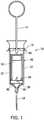
Fig. 1 is a side elevation in partial section of a syringe of the present invention;Fig. 2a is a cross section of a plunger rod of a first embodiment of the present invention prior to delivering buffering agent to a cartridge;Fig. 2b is a cross section of the plunger rod of a first embodiment after delivering buffering agent to the cartridge;Fig. 3 is a cross section of a plunger rod and cartridge system of a second embodiment; andFig. 4 is a cross section of a plunger rod of a third embodiment.- Corresponding reference characters indicate corresponding parts throughout the drawings.
- Referring to
Fig. 1 , a dental syringe of a first embodiment of the present invention is generally designated in its entirety by thereference number 10. Thedental syringe 10 generally comprises atubular barrel 12 and aplunger rod 14 slidably received in a head orproximal end 16 of the barrel. Aneedle 18 is connected to anoutlet 20 of the syringe at its distal end for dispensing anesthetic to tissue of a patient when theplunger rod 14 is forced distal. - A cartridge or carpule, generally designated by 30, loaded in a hollow interior of the
syringe barrel 12 holds the anesthetic before being dispensed. Thecartridge 30 includes atransparent cylinder 32 having aelastomeric diaphragm 34 held in place at itsdistal end 38 by aband 40, and an elastomeric stopper orpiston 42 positioned in aproximal end 44 of thecylinder 32. Thediaphragm 34 is pierced to put the anesthetic in communication with the dispensingneedle 18 of thesyringe 10. Theplunger rod 14 of thesyringe 10 engages thepiston 42 and forces the anesthetic out of thecylinder 32 and through the dispensingneedle 18. - As illustrated in
Fig. 2a , theplunger rod 14 includes atubular guide 50 having achannel 52 that slideably receives arod 54. Adistal end 56 of therod 54 includes asharp point 58 for penetrating thepiston 42 of thecartridge 30 as will be explained in more detail below. Aproximal end 60 of therod 54 includes aconventional thumb ring 62 for driving the rod through thecartridge piston 42. Acavity 64 is provided in therod 54 near itsdistal end 56 for holding abuffering agent 13 prior to delivering it to the cartridge. Adetent 66 is provided on therod 54 near thethumb ring 62 for connecting therod 54 to theguide 50 so they move in unison. - The distal end of the
guide 50 includes aflange 70 sized for receipt in theproximal end 44 of thecartridge 30 to center therod 54 on thepiston 42. Aproximal end 72 of theguide 50 also includes aflange 74 for centering the guide in thesyringe barrel 12. Agroove 76 is provided around thechannel 52 adjacent theproximal end 72 for receiving thedetent 66 on therod 54 to prevent movement between the rod and theguide 50. - As will be appreciated by those skilled in the art, when the
rod 54 is initially advanced, the rod moves distally inside theguide 50 so thesharp point 58 pierces thepiston 42 of thecartridge 30. As therod 54 advances farther, thecavity 64 enters the hollow interior of thecartridge 30 as shown inFig. 2b so thebuffering agent 13 mixes with the anesthetic in the cartridge, reducing the acidity of the anesthetic. Eventually, thedetent 66 on therod 54 engages thegroove 76 in thechannel 52 of theguide 50 so the guide advances with the rod. As theguide 50 advances, it forces thepiston 42 of thecartridge 30 distally in thecylinder 32, dispensing the contents of the cartridge through a needle extending through thediaphragm 34 of the cartridge. In addition, thedetent 66 permits thepiston 42 to be retracted by pulling back on thethumb ring 62 to aspirate anesthetic from the tissue as will be appreciated by those skilled in the art. In another embodiment, the anesthetic in thecartridge 30 may be at a negative pressure (i.e., a partial vacuum) to allow the buffer in the rod to easily exit the rod and mix with the anesthetic in the cartridge. Fig. 3 illustrates another embodiment of a cartridge, generally designated by 100. Thecartridge 100 includes atransparent cylinder 102 having an elastomeric diaphragm (not shown) held in place at its distal end by a band (not shown), and anelastomeric piston 110 positioned in aproximal end 112 of thecylinder 102. Thepiston 110 includes acavity 114 in itsproximal face 116. Thecavity 114 is filled withbuffering agent 13 and covered with afilm 118 to retain the agent in the cavity. As further illustrated inFig. 3 , aplunger rod 120 of the second embodiment has asharp point 124 for penetrating thefilm 118 and thepiston 110. Therod 120 also includes aflange 126 immediately proximal to thesharp point 124 and a second larger flange orbarb 128 positioned proximal to the first flange.- As will be appreciated by those skilled in the art, when the
plunger rod 120 is initially advanced, the rod moves distally so itssharp point 124 pierces thefilm 118. Moving farther, thesharp point 124 of therod 120 pierces thepiston 110. As therod 120 is advanced still farther, thefirst flange 126 pushes the buffering agent B through the opening in thepiston 110 created by thesharp point 124. As in the first embodiment, thebuffering agent 13 reduces the acidity of the anesthetic. Advancing therod 120 still farther engages thebarb 128 with thepiston 110, forcing it distally in thecylinder 102 to dispense the contents of the cartridge through a needle extending through the diaphragm (not shown) of thecartridge 100. Thebarb 128 permits thepiston 110 to be withdrawn, aspirating the tissue. - In a third embodiment illustrated in
Fig. 4 , abuffer delivery system 200 comprises atubular plunger 201 having achannel 202 extending between asharp point 204 at its distal end and athumb ring 206 at its proximal end. A rod 210 having acavity 212 extends through thechannel 202. When thetubular plunger 201 is initially advanced, itssharp point 204 pierces thepiston 42. Once thepiston 42 is pierced, the rod 210 is advanced until thecavity 212 enters the interior of thecylinder 32 dispensing the buffering agent into the anesthetic. Aflange 220 on extends from a proximal end of thetubular plunger 201 to engage the rod 210 when advanced. Alternatively, a flange (not shown) may be positioned at or near the distal end of thetubular plunger 201 to contact thepiston 42 to dispense the anesthetic.Barbs 222 at or near the distal end of thetubular plunger 201 may be configured to engage thepiston 42 to prevent separation from the piston during aspiration. Alternatively, barbs (not shown) may extend from rod 210 to engagepiston 42. - Having described the invention in detail, it will be apparent that modifications and variations are possible without departing from the scope of the invention defined in the appended claims. It is understood that embodiments of the invention may be used to deliver a two component drug in which the combination or mixing of the two components or two drugs is performed shortly before administration to the patient.
- When introducing elements of the present invention or the preferred embodiment(s) thereof, the articles "a", "an", "the", and "said" are intended to mean that there are one or more of the elements. The terms "comprising", "including", and "having" are intended to be inclusive and mean that there may be additional elements other than the listed elements.
- As various changes could be made in the above constructions, products, and methods without departing from the scope of the invention, it is intended that all matter contained in the above description and shown in the accompanying drawings shall be interpreted as illustrative and not in a limiting sense.
Claims (9)
- A syringe (10) for dispensing anesthetic from a cartridge (30) having an interior wall defining a hollow interior sized and shaped for receiving a dose of anesthetic, and a piston (42), the syringe comprising:a tubular plunger (50,201) slidably received in the hollow interior of the tubular cartridge (30), said plunger (50,201) having a hollow interior (52,202) extending between a distal end (70,204) shaped for engaging the piston (42) and an open proximal end (72,206) opposite the distal end; anda plunger rod (54,210) slidably received in the hollow interior (52,202) of the tubular plunger (50,201),characterized by the rod (54,210) having a sharp distal end (56) adapted to penetrate the piston (42), a proximal end (60), and a length extending between the distal end (56) and the proximal end (60) sized so that a delivery portion of the rod (54,210) extends through the piston (42) into the cartridge (30) when the rod (54,210) is driven through the piston (42),characterised in that
said delivery portion including a recess (64,212) for receiving a buffering agent (13) to reduce acidity of the dose of anesthetic. - A syringe as set forth in claim 1 wherein the recess (64,212) is located in a side of the plunger rod (54,210).
- A syringe as set forth in claim 2 wherein the recess (64,212) is spaced from the sharp distal end (56) of the plunger rod (54,210).
- A syringe as set forth in claim 1 wherein the recess (64,212) is spaced from the sharp distal end (56) of the plunger rod (54,210).
- A syringe as set forth in claim 1 wherein at least one of the rod (54) and the plunger (50) includes a detent (66) and at least another of the rod (54) and the plunger (50) includes a corresponding opening (76) for receiving the detent (66) for retaining the relative position of the rod (54) in the plunger (50).
- A syringe as set forth in claim 5 wherein the rod (54) includes a detent (66) and the plunger (50) includes a corresponding opening (76) for receiving the detent (66) for retaining the relative position of the rod (54) in the plunger (50).
- A syringe and cartridge system comprising:
a cartridge (100) having an interior wall defining a hollow interior sized and shaped for receiving a dose of anesthetic, and a piston (110) slidably engaging the interior wall,characterized by the piston (110) having a distal face facing the dose of anesthetic in the hollow interior of the cartridge (100), a proximal face (116) opposite the distal face,
characterised in that
it comprises a recess (114) in the proximal face (116) for receiving a predetermined amount of buffering agent (13), and a sheet (118) sealing the buffering agent (13) in the recess (114); and
a plunger rod (120) having a sharp distal end (124) adapted to penetrate the sheet (118) and piston (110) forming a hole through the piston (110), the buffering agent (13) entering the hollow interior of the cartridge (100) to reduce acidity of the dose of anesthetic therein, the syringe and cartridge system further comprising a flange (126) adjacent the distal end (124) of the plunger rod (120) for pushing the buffering agent (13) through the hole formed through the piston (110) and into the hollow interior of the cartridge (100); and a barb (128) for preventing further movement of the rod (120) with respect to the piston (110) once the buffering agent (13) is pushed into the hollow interior of the cartridge (100). - A syringe and cartridge system as set forth in claim 7 wherein the barb (128) comprises a conical portion.
- A syringe and cartridge system as set forth in claim 7 wherein the rod (120) includes a thumb ring at a proximal end opposite the distal end for moving the rod (120) relative to the cartridge (100).
Applications Claiming Priority (1)
| Application Number | Priority Date | Filing Date | Title |
|---|---|---|---|
| US201161471913P | 2011-04-05 | 2011-04-05 |
Publications (2)
| Publication Number | Publication Date |
|---|---|
| EP2508219A1 EP2508219A1 (en) | 2012-10-10 |
| EP2508219B1true EP2508219B1 (en) | 2018-06-06 |
Family
ID=46000786
Family Applications (1)
| Application Number | Title | Priority Date | Filing Date |
|---|---|---|---|
| EP12162969.5ANot-in-forceEP2508219B1 (en) | 2011-04-05 | 2012-04-03 | Buffering agent delivery system for anesthetic syringe |
Country Status (5)
| Country | Link |
|---|---|
| US (3) | US8672878B2 (en) |
| EP (1) | EP2508219B1 (en) |
| JP (2) | JP5367864B2 (en) |
| AU (1) | AU2012201965B2 (en) |
| CA (1) | CA2773480C (en) |
Families Citing this family (10)
| Publication number | Priority date | Publication date | Assignee | Title |
|---|---|---|---|---|
| WO2012104376A1 (en)* | 2011-02-02 | 2012-08-09 | Bioneer A/S | A syringe |
| CA2876946A1 (en)* | 2012-06-26 | 2014-01-03 | Bioneer A/S | A syringe with a hollow plunger |
| US9855385B2 (en)* | 2013-03-13 | 2018-01-02 | Bayer Healthcare Llc | Multiple compartment syringe |
| DE102013104003B3 (en)* | 2013-04-19 | 2014-03-13 | Glatt Systemtechnik Gmbh | Device for introducing a defined amount of a second powder into a process container |
| USD828653S1 (en) | 2016-12-14 | 2018-09-11 | Brandon Penland | Treatment applicator |
| US10569069B2 (en) | 2016-12-14 | 2020-02-25 | Combat Comb, Llc | Applicator for treatments applied to animal skin |
| US20200046609A1 (en) | 2017-01-01 | 2020-02-13 | John Scott Keadle | Mixing vial |
| US11305064B2 (en) | 2017-01-01 | 2022-04-19 | Balanced Pharma Incorporated | Mixing vial |
| US10307336B1 (en) | 2018-12-17 | 2019-06-04 | John C. Sands | System and method for mixing and delivering a solution |
| US20240207524A1 (en)* | 2020-08-12 | 2024-06-27 | Yasser Sadek | One-step anesthetic buffering carpule |
Family Cites Families (25)
| Publication number | Priority date | Publication date | Assignee | Title |
|---|---|---|---|---|
| US1661818A (en)* | 1922-03-02 | 1928-03-06 | Cook Lab Inc | Hypodermic syringe and cartridge therefor |
| GB787963A (en)* | 1954-09-01 | 1957-12-18 | Hoechst Ag | An injection syringe for use with cylindrical ampoules |
| US2869542A (en)* | 1957-02-01 | 1959-01-20 | Leo A Orsten | Universal aspirating syringe for long and short cartridges |
| US3684136A (en)* | 1971-02-22 | 1972-08-15 | Erwin H Baumann | Receptacle having a dividing wall |
| US4767413A (en)* | 1987-04-20 | 1988-08-30 | Habley Medical Technology Corporation | Dental syringe having an automatically retractable needle |
| DE4206300A1 (en) | 1991-11-29 | 1993-06-03 | Sergej Michailovic Masurik | INJECTION SYRINGE |
| US5637087A (en)* | 1995-03-22 | 1997-06-10 | Abbott Laboratories | Prefilled, two-constituent syringe |
| US5603695A (en)* | 1995-06-07 | 1997-02-18 | Erickson; Kim | Device for alkalizing local anesthetic injection medication |
| US5601534A (en)* | 1995-06-07 | 1997-02-11 | The University Of Memphis | Disposable hypodermic syringe and needle combination |
| US6080132A (en)* | 1998-02-27 | 2000-06-27 | Abbott Laboratories | Apparatus for altering characteristics of a fluid |
| US7983734B2 (en)* | 2003-05-23 | 2011-07-19 | Senorx, Inc. | Fibrous marker and intracorporeal delivery thereof |
| US6443152B1 (en)* | 2001-01-12 | 2002-09-03 | Becton Dickinson And Company | Medicament respiratory delivery device |
| US7850663B2 (en)* | 2001-01-12 | 2010-12-14 | Becton, Dickinson And Company | Medicament microdevice delivery system, cartridge and method of use |
| JP4112851B2 (en)* | 2001-11-27 | 2008-07-02 | テルモ株式会社 | Two-chamber prefilled syringe |
| DE10218782A1 (en)* | 2002-04-22 | 2003-11-20 | Pfeiffer Erich Gmbh & Co Kg | Dosing device with at least two media rooms |
| JP4168237B2 (en)* | 2002-07-15 | 2008-10-22 | ニプロ株式会社 | Two-component prefilled syringe |
| US7883490B2 (en)* | 2002-10-23 | 2011-02-08 | Boston Scientific Scimed, Inc. | Mixing and delivery of therapeutic compositions |
| DE20218493U1 (en)* | 2002-11-28 | 2004-04-08 | Chemische Fabrik Kreussler & Co. Gmbh | Device for producing medical foam |
| US7329235B2 (en)* | 2004-08-02 | 2008-02-12 | Bertron Kim W | Powder and liquid mixing syringe |
| US7870637B2 (en) | 2004-12-10 | 2011-01-18 | Techtronic Floor Care Technology Limited | Stacked tank arrangement for a cleaning apparatus |
| US20080171971A1 (en)* | 2005-11-16 | 2008-07-17 | Diperna Paul Mario | Novel enhanced device and technique for mixing and dispensing a preserved agent |
| CN101130120A (en)* | 2006-08-24 | 2008-02-27 | 郑万章 | Local disposable type agent tube needle cylinder |
| DE102008030270A1 (en)* | 2008-06-19 | 2009-12-24 | Arzneimittel Gmbh Apotheker Vetter & Co. Ravensburg | Device having at least one chamber for receiving a medicament or a sample volume |
| US8142403B2 (en)* | 2008-06-30 | 2012-03-27 | Tyco Healthcare Group Lp | Syringe assembly with plunger having a secondary dispensing reservoir |
| JP5795571B2 (en)* | 2009-04-15 | 2015-10-14 | ベクトン・ディキンソン・アンド・カンパニーBecton, Dickinson And Company | Fixing member and device enabling mixing in a pen-type syringe |
- 2012
- 2012-04-03CACA2773480Apatent/CA2773480C/ennot_activeExpired - Fee Related
- 2012-04-03EPEP12162969.5Apatent/EP2508219B1/ennot_activeNot-in-force
- 2012-04-04AUAU2012201965Apatent/AU2012201965B2/ennot_activeCeased
- 2012-04-04JPJP2012085534Apatent/JP5367864B2/ennot_activeExpired - Fee Related
- 2012-04-04USUS13/438,856patent/US8672878B2/enactiveActive
- 2013
- 2013-07-24JPJP2013153370Apatent/JP5619231B2/ennot_activeExpired - Fee Related
- 2014
- 2014-03-03USUS14/195,148patent/US8974407B2/enactiveActive
- 2015
- 2015-03-02USUS14/635,263patent/US9265894B2/enactiveActive
Non-Patent Citations (1)
| Title |
|---|
| None* |
Also Published As
| Publication number | Publication date |
|---|---|
| AU2012201965A1 (en) | 2012-10-25 |
| US8672878B2 (en) | 2014-03-18 |
| US20150238702A1 (en) | 2015-08-27 |
| CA2773480A1 (en) | 2012-10-05 |
| JP5619231B2 (en) | 2014-11-05 |
| AU2012201965B2 (en) | 2013-02-14 |
| JP5367864B2 (en) | 2013-12-11 |
| EP2508219A1 (en) | 2012-10-10 |
| JP2012217848A (en) | 2012-11-12 |
| CA2773480C (en) | 2014-12-30 |
| US20120259279A1 (en) | 2012-10-11 |
| JP2013236958A (en) | 2013-11-28 |
| US9265894B2 (en) | 2016-02-23 |
| US20140221918A1 (en) | 2014-08-07 |
| US8974407B2 (en) | 2015-03-10 |
Similar Documents
| Publication | Publication Date | Title |
|---|---|---|
| EP2508219B1 (en) | Buffering agent delivery system for anesthetic syringe | |
| US6132400A (en) | Dual-chamber syringe and methods | |
| US5755696A (en) | Syringe filling and delivery device | |
| EP2542282B1 (en) | Injection device | |
| EP0820778A1 (en) | Syringe filling and delivery device | |
| CN209809034U (en) | Adapter, container assembly and syringe assembly | |
| AU2011261226B2 (en) | Systems and methods for a medical syringe | |
| US9375385B2 (en) | Pre-filled active vial having integral plunger assembly | |
| AU2013205363B2 (en) | Buffering agent delivery system for anesthetic syringe | |
| US10786433B2 (en) | Buffering agent cartridge | |
| EP2508216B1 (en) | Medicine delivery system | |
| US20250312528A1 (en) | Automatic Anesthetic Buffering System And Method | |
| US20240424218A1 (en) | Vial-to-syringe converter and methods of making and using same | |
| WO2025190778A1 (en) | Stoppering tool system and method with improved stopper centering for installation in a syringe barrel | |
| HK1185824B (en) | Reusable auto-injector | |
| HK1185824A1 (en) | Reusable auto-injector | |
| HK1131574A (en) | Breech loaded fixed needle syringe and automatic injection device having the same |
Legal Events
| Date | Code | Title | Description |
|---|---|---|---|
| PUAI | Public reference made under article 153(3) epc to a published international application that has entered the european phase | Free format text:ORIGINAL CODE: 0009012 | |
| 17P | Request for examination filed | Effective date:20120403 | |
| AK | Designated contracting states | Kind code of ref document:A1 Designated state(s):AL AT BE BG CH CY CZ DE DK EE ES FI FR GB GR HR HU IE IS IT LI LT LU LV MC MK MT NL NO PL PT RO RS SE SI SK SM TR | |
| AX | Request for extension of the european patent | Extension state:BA ME | |
| RAP1 | Party data changed (applicant data changed or rights of an application transferred) | Owner name:COVIDIEN LP | |
| 17Q | First examination report despatched | Effective date:20150818 | |
| REG | Reference to a national code | Ref country code:DE Ref legal event code:R079 Ref document number:602012047103 Country of ref document:DE Free format text:PREVIOUS MAIN CLASS: A61M0005320000 Ipc:A61M0005315000 | |
| GRAP | Despatch of communication of intention to grant a patent | Free format text:ORIGINAL CODE: EPIDOSNIGR1 | |
| STAA | Information on the status of an ep patent application or granted ep patent | Free format text:STATUS: GRANT OF PATENT IS INTENDED | |
| GRAJ | Information related to disapproval of communication of intention to grant by the applicant or resumption of examination proceedings by the epo deleted | Free format text:ORIGINAL CODE: EPIDOSDIGR1 | |
| GRAP | Despatch of communication of intention to grant a patent | Free format text:ORIGINAL CODE: EPIDOSNIGR1 | |
| RIC1 | Information provided on ipc code assigned before grant | Ipc:A61M 5/31 20060101ALI20170929BHEP Ipc:A61M 5/24 20060101ALI20170929BHEP Ipc:A61M 5/315 20060101AFI20170929BHEP | |
| INTG | Intention to grant announced | Effective date:20171024 | |
| INTG | Intention to grant announced | Effective date:20171103 | |
| RAP1 | Party data changed (applicant data changed or rights of an application transferred) | Owner name:KPR U.S., LLC | |
| GRAS | Grant fee paid | Free format text:ORIGINAL CODE: EPIDOSNIGR3 | |
| GRAA | (expected) grant | Free format text:ORIGINAL CODE: 0009210 | |
| STAA | Information on the status of an ep patent application or granted ep patent | Free format text:STATUS: THE PATENT HAS BEEN GRANTED | |
| AK | Designated contracting states | Kind code of ref document:B1 Designated state(s):AL AT BE BG CH CY CZ DE DK EE ES FI FR GB GR HR HU IE IS IT LI LT LU LV MC MK MT NL NO PL PT RO RS SE SI SK SM TR | |
| REG | Reference to a national code | Ref country code:GB Ref legal event code:FG4D | |
| REG | Reference to a national code | Ref country code:CH Ref legal event code:EP Ref country code:AT Ref legal event code:REF Ref document number:1005348 Country of ref document:AT Kind code of ref document:T Effective date:20180615 | |
| REG | Reference to a national code | Ref country code:IE Ref legal event code:FG4D | |
| REG | Reference to a national code | Ref country code:DE Ref legal event code:R096 Ref document number:602012047103 Country of ref document:DE | |
| REG | Reference to a national code | Ref country code:NL Ref legal event code:MP Effective date:20180606 | |
| REG | Reference to a national code | Ref country code:LT Ref legal event code:MG4D | |
| PG25 | Lapsed in a contracting state [announced via postgrant information from national office to epo] | Ref country code:ES Free format text:LAPSE BECAUSE OF FAILURE TO SUBMIT A TRANSLATION OF THE DESCRIPTION OR TO PAY THE FEE WITHIN THE PRESCRIBED TIME-LIMIT Effective date:20180606 Ref country code:LT Free format text:LAPSE BECAUSE OF FAILURE TO SUBMIT A TRANSLATION OF THE DESCRIPTION OR TO PAY THE FEE WITHIN THE PRESCRIBED TIME-LIMIT Effective date:20180606 Ref country code:CY Free format text:LAPSE BECAUSE OF FAILURE TO SUBMIT A TRANSLATION OF THE DESCRIPTION OR TO PAY THE FEE WITHIN THE PRESCRIBED TIME-LIMIT Effective date:20180606 Ref country code:FI Free format text:LAPSE BECAUSE OF FAILURE TO SUBMIT A TRANSLATION OF THE DESCRIPTION OR TO PAY THE FEE WITHIN THE PRESCRIBED TIME-LIMIT Effective date:20180606 Ref country code:NO Free format text:LAPSE BECAUSE OF FAILURE TO SUBMIT A TRANSLATION OF THE DESCRIPTION OR TO PAY THE FEE WITHIN THE PRESCRIBED TIME-LIMIT Effective date:20180906 Ref country code:BG Free format text:LAPSE BECAUSE OF FAILURE TO SUBMIT A TRANSLATION OF THE DESCRIPTION OR TO PAY THE FEE WITHIN THE PRESCRIBED TIME-LIMIT Effective date:20180906 Ref country code:SE Free format text:LAPSE BECAUSE OF FAILURE TO SUBMIT A TRANSLATION OF THE DESCRIPTION OR TO PAY THE FEE WITHIN THE PRESCRIBED TIME-LIMIT Effective date:20180606 | |
| PG25 | Lapsed in a contracting state [announced via postgrant information from national office to epo] | Ref country code:HR Free format text:LAPSE BECAUSE OF FAILURE TO SUBMIT A TRANSLATION OF THE DESCRIPTION OR TO PAY THE FEE WITHIN THE PRESCRIBED TIME-LIMIT Effective date:20180606 Ref country code:GR Free format text:LAPSE BECAUSE OF FAILURE TO SUBMIT A TRANSLATION OF THE DESCRIPTION OR TO PAY THE FEE WITHIN THE PRESCRIBED TIME-LIMIT Effective date:20180907 Ref country code:LV Free format text:LAPSE BECAUSE OF FAILURE TO SUBMIT A TRANSLATION OF THE DESCRIPTION OR TO PAY THE FEE WITHIN THE PRESCRIBED TIME-LIMIT Effective date:20180606 Ref country code:RS Free format text:LAPSE BECAUSE OF FAILURE TO SUBMIT A TRANSLATION OF THE DESCRIPTION OR TO PAY THE FEE WITHIN THE PRESCRIBED TIME-LIMIT Effective date:20180606 | |
| REG | Reference to a national code | Ref country code:AT Ref legal event code:MK05 Ref document number:1005348 Country of ref document:AT Kind code of ref document:T Effective date:20180606 | |
| PG25 | Lapsed in a contracting state [announced via postgrant information from national office to epo] | Ref country code:NL Free format text:LAPSE BECAUSE OF FAILURE TO SUBMIT A TRANSLATION OF THE DESCRIPTION OR TO PAY THE FEE WITHIN THE PRESCRIBED TIME-LIMIT Effective date:20180606 | |
| PG25 | Lapsed in a contracting state [announced via postgrant information from national office to epo] | Ref country code:SK Free format text:LAPSE BECAUSE OF FAILURE TO SUBMIT A TRANSLATION OF THE DESCRIPTION OR TO PAY THE FEE WITHIN THE PRESCRIBED TIME-LIMIT Effective date:20180606 Ref country code:PL Free format text:LAPSE BECAUSE OF FAILURE TO SUBMIT A TRANSLATION OF THE DESCRIPTION OR TO PAY THE FEE WITHIN THE PRESCRIBED TIME-LIMIT Effective date:20180606 Ref country code:CZ Free format text:LAPSE BECAUSE OF FAILURE TO SUBMIT A TRANSLATION OF THE DESCRIPTION OR TO PAY THE FEE WITHIN THE PRESCRIBED TIME-LIMIT Effective date:20180606 Ref country code:EE Free format text:LAPSE BECAUSE OF FAILURE TO SUBMIT A TRANSLATION OF THE DESCRIPTION OR TO PAY THE FEE WITHIN THE PRESCRIBED TIME-LIMIT Effective date:20180606 Ref country code:IS Free format text:LAPSE BECAUSE OF FAILURE TO SUBMIT A TRANSLATION OF THE DESCRIPTION OR TO PAY THE FEE WITHIN THE PRESCRIBED TIME-LIMIT Effective date:20181006 Ref country code:AT Free format text:LAPSE BECAUSE OF FAILURE TO SUBMIT A TRANSLATION OF THE DESCRIPTION OR TO PAY THE FEE WITHIN THE PRESCRIBED TIME-LIMIT Effective date:20180606 Ref country code:RO Free format text:LAPSE BECAUSE OF FAILURE TO SUBMIT A TRANSLATION OF THE DESCRIPTION OR TO PAY THE FEE WITHIN THE PRESCRIBED TIME-LIMIT Effective date:20180606 | |
| PG25 | Lapsed in a contracting state [announced via postgrant information from national office to epo] | Ref country code:SM Free format text:LAPSE BECAUSE OF FAILURE TO SUBMIT A TRANSLATION OF THE DESCRIPTION OR TO PAY THE FEE WITHIN THE PRESCRIBED TIME-LIMIT Effective date:20180606 Ref country code:IT Free format text:LAPSE BECAUSE OF FAILURE TO SUBMIT A TRANSLATION OF THE DESCRIPTION OR TO PAY THE FEE WITHIN THE PRESCRIBED TIME-LIMIT Effective date:20180606 | |
| REG | Reference to a national code | Ref country code:DE Ref legal event code:R097 Ref document number:602012047103 Country of ref document:DE | |
| PLBE | No opposition filed within time limit | Free format text:ORIGINAL CODE: 0009261 | |
| STAA | Information on the status of an ep patent application or granted ep patent | Free format text:STATUS: NO OPPOSITION FILED WITHIN TIME LIMIT | |
| 26N | No opposition filed | Effective date:20190307 | |
| PG25 | Lapsed in a contracting state [announced via postgrant information from national office to epo] | Ref country code:DK Free format text:LAPSE BECAUSE OF FAILURE TO SUBMIT A TRANSLATION OF THE DESCRIPTION OR TO PAY THE FEE WITHIN THE PRESCRIBED TIME-LIMIT Effective date:20180606 Ref country code:SI Free format text:LAPSE BECAUSE OF FAILURE TO SUBMIT A TRANSLATION OF THE DESCRIPTION OR TO PAY THE FEE WITHIN THE PRESCRIBED TIME-LIMIT Effective date:20180606 | |
| PG25 | Lapsed in a contracting state [announced via postgrant information from national office to epo] | Ref country code:AL Free format text:LAPSE BECAUSE OF FAILURE TO SUBMIT A TRANSLATION OF THE DESCRIPTION OR TO PAY THE FEE WITHIN THE PRESCRIBED TIME-LIMIT Effective date:20180606 | |
| REG | Reference to a national code | Ref country code:CH Ref legal event code:PL | |
| REG | Reference to a national code | Ref country code:BE Ref legal event code:MM Effective date:20190430 | |
| PG25 | Lapsed in a contracting state [announced via postgrant information from national office to epo] | Ref country code:LU Free format text:LAPSE BECAUSE OF NON-PAYMENT OF DUE FEES Effective date:20190403 Ref country code:MC Free format text:LAPSE BECAUSE OF FAILURE TO SUBMIT A TRANSLATION OF THE DESCRIPTION OR TO PAY THE FEE WITHIN THE PRESCRIBED TIME-LIMIT Effective date:20180606 | |
| PG25 | Lapsed in a contracting state [announced via postgrant information from national office to epo] | Ref country code:LI Free format text:LAPSE BECAUSE OF NON-PAYMENT OF DUE FEES Effective date:20190430 Ref country code:CH Free format text:LAPSE BECAUSE OF NON-PAYMENT OF DUE FEES Effective date:20190430 | |
| PG25 | Lapsed in a contracting state [announced via postgrant information from national office to epo] | Ref country code:BE Free format text:LAPSE BECAUSE OF NON-PAYMENT OF DUE FEES Effective date:20190430 | |
| PG25 | Lapsed in a contracting state [announced via postgrant information from national office to epo] | Ref country code:TR Free format text:LAPSE BECAUSE OF FAILURE TO SUBMIT A TRANSLATION OF THE DESCRIPTION OR TO PAY THE FEE WITHIN THE PRESCRIBED TIME-LIMIT Effective date:20180606 | |
| PG25 | Lapsed in a contracting state [announced via postgrant information from national office to epo] | Ref country code:IE Free format text:LAPSE BECAUSE OF NON-PAYMENT OF DUE FEES Effective date:20190403 | |
| PG25 | Lapsed in a contracting state [announced via postgrant information from national office to epo] | Ref country code:PT Free format text:LAPSE BECAUSE OF FAILURE TO SUBMIT A TRANSLATION OF THE DESCRIPTION OR TO PAY THE FEE WITHIN THE PRESCRIBED TIME-LIMIT Effective date:20181008 | |
| PGFP | Annual fee paid to national office [announced via postgrant information from national office to epo] | Ref country code:FR Payment date:20200427 Year of fee payment:9 Ref country code:DE Payment date:20200429 Year of fee payment:9 | |
| PGFP | Annual fee paid to national office [announced via postgrant information from national office to epo] | Ref country code:GB Payment date:20200427 Year of fee payment:9 | |
| PG25 | Lapsed in a contracting state [announced via postgrant information from national office to epo] | Ref country code:HU Free format text:LAPSE BECAUSE OF FAILURE TO SUBMIT A TRANSLATION OF THE DESCRIPTION OR TO PAY THE FEE WITHIN THE PRESCRIBED TIME-LIMIT; INVALID AB INITIO Effective date:20120403 Ref country code:MT Free format text:LAPSE BECAUSE OF FAILURE TO SUBMIT A TRANSLATION OF THE DESCRIPTION OR TO PAY THE FEE WITHIN THE PRESCRIBED TIME-LIMIT Effective date:20180606 | |
| REG | Reference to a national code | Ref country code:DE Ref legal event code:R119 Ref document number:602012047103 Country of ref document:DE | |
| GBPC | Gb: european patent ceased through non-payment of renewal fee | Effective date:20210403 | |
| PG25 | Lapsed in a contracting state [announced via postgrant information from national office to epo] | Ref country code:DE Free format text:LAPSE BECAUSE OF NON-PAYMENT OF DUE FEES Effective date:20211103 Ref country code:GB Free format text:LAPSE BECAUSE OF NON-PAYMENT OF DUE FEES Effective date:20210403 Ref country code:FR Free format text:LAPSE BECAUSE OF NON-PAYMENT OF DUE FEES Effective date:20210430 | |
| PG25 | Lapsed in a contracting state [announced via postgrant information from national office to epo] | Ref country code:MK Free format text:LAPSE BECAUSE OF FAILURE TO SUBMIT A TRANSLATION OF THE DESCRIPTION OR TO PAY THE FEE WITHIN THE PRESCRIBED TIME-LIMIT Effective date:20180606 |