EP2507746B1 - Rfid condition latching - Google Patents
Rfid condition latchingDownload PDFInfo
- Publication number
- EP2507746B1 EP2507746B1EP10788172.4AEP10788172AEP2507746B1EP 2507746 B1EP2507746 B1EP 2507746B1EP 10788172 AEP10788172 AEP 10788172AEP 2507746 B1EP2507746 B1EP 2507746B1
- Authority
- EP
- European Patent Office
- Prior art keywords
- rfid
- state
- chip
- switch
- integrated circuit
- Prior art date
- Legal status (The legal status is an assumption and is not a legal conclusion. Google has not performed a legal analysis and makes no representation as to the accuracy of the status listed.)
- Not-in-force
Links
Images


Classifications
- G—PHYSICS
- G06—COMPUTING OR CALCULATING; COUNTING
- G06K—GRAPHICAL DATA READING; PRESENTATION OF DATA; RECORD CARRIERS; HANDLING RECORD CARRIERS
- G06K19/00—Record carriers for use with machines and with at least a part designed to carry digital markings
- G06K19/06—Record carriers for use with machines and with at least a part designed to carry digital markings characterised by the kind of the digital marking, e.g. shape, nature, code
- G06K19/067—Record carriers with conductive marks, printed circuits or semiconductor circuit elements, e.g. credit or identity cards also with resonating or responding marks without active components
- G06K19/07—Record carriers with conductive marks, printed circuits or semiconductor circuit elements, e.g. credit or identity cards also with resonating or responding marks without active components with integrated circuit chips
- G06K19/0723—Record carriers with conductive marks, printed circuits or semiconductor circuit elements, e.g. credit or identity cards also with resonating or responding marks without active components with integrated circuit chips the record carrier comprising an arrangement for non-contact communication, e.g. wireless communication circuits on transponder cards, non-contact smart cards or RFIDs
- G—PHYSICS
- G06—COMPUTING OR CALCULATING; COUNTING
- G06K—GRAPHICAL DATA READING; PRESENTATION OF DATA; RECORD CARRIERS; HANDLING RECORD CARRIERS
- G06K19/00—Record carriers for use with machines and with at least a part designed to carry digital markings
- G06K19/06—Record carriers for use with machines and with at least a part designed to carry digital markings characterised by the kind of the digital marking, e.g. shape, nature, code
- G06K19/067—Record carriers with conductive marks, printed circuits or semiconductor circuit elements, e.g. credit or identity cards also with resonating or responding marks without active components
- G06K19/07—Record carriers with conductive marks, printed circuits or semiconductor circuit elements, e.g. credit or identity cards also with resonating or responding marks without active components with integrated circuit chips
- G06K19/0701—Record carriers with conductive marks, printed circuits or semiconductor circuit elements, e.g. credit or identity cards also with resonating or responding marks without active components with integrated circuit chips at least one of the integrated circuit chips comprising an arrangement for power management
- G06K19/0707—Record carriers with conductive marks, printed circuits or semiconductor circuit elements, e.g. credit or identity cards also with resonating or responding marks without active components with integrated circuit chips at least one of the integrated circuit chips comprising an arrangement for power management the arrangement being capable of collecting energy from external energy sources, e.g. thermocouples, vibration, electromagnetic radiation
- G—PHYSICS
- G06—COMPUTING OR CALCULATING; COUNTING
- G06K—GRAPHICAL DATA READING; PRESENTATION OF DATA; RECORD CARRIERS; HANDLING RECORD CARRIERS
- G06K19/00—Record carriers for use with machines and with at least a part designed to carry digital markings
- G06K19/06—Record carriers for use with machines and with at least a part designed to carry digital markings characterised by the kind of the digital marking, e.g. shape, nature, code
- G06K19/067—Record carriers with conductive marks, printed circuits or semiconductor circuit elements, e.g. credit or identity cards also with resonating or responding marks without active components
- G06K19/07—Record carriers with conductive marks, printed circuits or semiconductor circuit elements, e.g. credit or identity cards also with resonating or responding marks without active components with integrated circuit chips
- G06K19/0701—Record carriers with conductive marks, printed circuits or semiconductor circuit elements, e.g. credit or identity cards also with resonating or responding marks without active components with integrated circuit chips at least one of the integrated circuit chips comprising an arrangement for power management
- G06K19/0712—Record carriers with conductive marks, printed circuits or semiconductor circuit elements, e.g. credit or identity cards also with resonating or responding marks without active components with integrated circuit chips at least one of the integrated circuit chips comprising an arrangement for power management the arrangement being capable of triggering distinct operating modes or functions dependent on the strength of an energy or interrogation field in the proximity of the record carrier
- G—PHYSICS
- G06—COMPUTING OR CALCULATING; COUNTING
- G06K—GRAPHICAL DATA READING; PRESENTATION OF DATA; RECORD CARRIERS; HANDLING RECORD CARRIERS
- G06K19/00—Record carriers for use with machines and with at least a part designed to carry digital markings
- G06K19/06—Record carriers for use with machines and with at least a part designed to carry digital markings characterised by the kind of the digital marking, e.g. shape, nature, code
- G06K19/067—Record carriers with conductive marks, printed circuits or semiconductor circuit elements, e.g. credit or identity cards also with resonating or responding marks without active components
- G06K19/07—Record carriers with conductive marks, printed circuits or semiconductor circuit elements, e.g. credit or identity cards also with resonating or responding marks without active components with integrated circuit chips
- G06K19/0716—Record carriers with conductive marks, printed circuits or semiconductor circuit elements, e.g. credit or identity cards also with resonating or responding marks without active components with integrated circuit chips at least one of the integrated circuit chips comprising a sensor or an interface to a sensor
- G06K19/0717—Record carriers with conductive marks, printed circuits or semiconductor circuit elements, e.g. credit or identity cards also with resonating or responding marks without active components with integrated circuit chips at least one of the integrated circuit chips comprising a sensor or an interface to a sensor the sensor being capable of sensing environmental conditions such as temperature history or pressure
Definitions
- the present inventionrelates generally to radio-frequency identification (RFID) technology, and in particular relates to RFID-based systems and methods for detecting that a condition has occurred in an RFID tag even when the RFID tag is not powered, by storing and managing power in RFID tags.
- RFIDradio-frequency identification
- Radio-frequency identificationis a remote recognition technique that utilizes RFID tags having information stored therein, usually in an integrated circuit (IC). The stored information is retrievable via RF communication between the RFID tag and an RFID tag reader.
- RFID systemsutilize hand-held RFID readers that when brought sufficiently close to an RFID tag are able to read an RFID tag signal either emitted by or backscattered from the tag.
- RFID systemsare used for a variety of applications, including inventory management and product tracking in a number of different industries, as well as in libraries and hospitals.
- RFID tagsgenerally come in three varieties: passive, semi-passive, and active.
- Passive RFID tagshave no energy or power source of their own and operate by harvesting energy from the RF signal (field) generated by the RFID-tag reader.
- Passive tagscommunicate back to the reader by modulating and back-scattering the RF signal from the RF reader.
- Semi-passive RFID tagscommunicate to the reader in the same way via modulation of the back-scattered reader RF signal, but they do not rely on harvesting energy from the reader field to power the RFID tag IC. Instead, semi-passive tags generally have their own power source, usually in the form of one or more batteries.
- semi-passive RFID tagsusually have significantly greater read ranges than passive tags.
- Active tagsalso have a power source such as a battery that not only powers the RFID tag IC but that can also actively generate and transmits radiation to the RFID reader.
- RFID tagscan be designed to operate at different RF frequencies. At low frequencies (e.g., 100-130 KHz s) RFID tags often communicate via mutual inductance coupling between an RFID-reader coil antenna and an RFID-tag coil antenna. At these frequencies, the RFID reader's RF signal is not strongly absorbed by water. Since the user's hand is primarily composed of water, this means that at low RF frequencies the RF signal can penetrate the user's hand and enable two-way communication between the RFID tag and the RFID reader.
- low frequenciese.g. 100-130 KHz s
- RFID tagsoften communicate via mutual inductance coupling between an RFID-reader coil antenna and an RFID-tag coil antenna. At these frequencies, the RFID reader's RF signal is not strongly absorbed by water. Since the user's hand is primarily composed of water, this means that at low RF frequencies the RF signal can penetrate the user's hand and enable two-way communication between the RFID tag and the RFID reader.
- This low frequency inductance coupling approachis practical as long as the distance between the tag and the reader is a fraction of the wavelength of the RF signal.
- the required separation between the RFID tag and the RFID readeri.e., the "read distance”
- the separation distance between RFID tags and RFID readers in typical item-identification applications within telecommunications data centersis expected to be 1 m to 3 m. Therefore, the low frequency RFID tag solution is not a practical approach for this and other such applications.
- RFID tags designed to operate at higher frequenciestypically operate by the RFID tag capturing far-field radiation from the RFID reader antenna transmission using a local monopole, dipole or modified dipole antenna (e.g., a "squiggle antenna").
- a local monopole, dipole or modified dipole antennae.g., a "squiggle antenna”
- the electric signal formed by the RFID tag antennais processed by a rectifier circuit in the RFID tag's IC chip, yielding energy that powers the rest of the IC chip and enables the IC chip to transmit a return signal to the RFID reader.
- communication with the RFID readeris often via backscatter modulation of the RFID reader signal rather than by independent RF signal transmission from the RFID tag.
- Ultra-high-frequency RFID tagscan communicate with RFID readers at much greater read distances (e.g., 5 to 10 m) than low frequency RFID tags (1 m or less). Ultra-high-frequency RFID tags are thus better suited for applications involving the RFID identification of hand-held items.
- a problem with using ultra-high frequency RFID tags for the identification of hand-held itemsarises due to the strong absorption of high-frequency RF signal power by water.
- water in the user's handattenuates the reader's RF signal when the hand blocks the RF communication path. Even in cases where the user's hand only partially blocks the RF communication path, it can still significantly reduce the RF signal strength. In this situation, the RFID tag may not receive sufficient energy to power its internal circuitry. Likewise, the RFID tag's response to the RFID reader may be impeded by the presence of the user's hand.
- US 2008/0100456 A1discloses condition RFID tags associated with condition responsive devices.
- the condition responsive devicesare responsive to one or more conditions and/or change in condition such as a state of contact, electrical contact closure, temperature, pressure, humidity, light, or capacitance (and/or impedance).
- the condition responsive devicemay be user-operated, for example by pressing a push button or connecting or disconnecting a plug from a socket, or the condition responsive device may be a passively operated sensor, or both could be employed together.
- the condition and/or change in condition indicated by the condition responsive devicemay permit or preclude operation of a given RFID transponder. Alternatively, such condition and/or change in condition may simply be registered and/or reported by the RFID transponder without altering the operational status of the RFID transponder.
- WO 2009/091888 A1discloses patch cable connectors, adapters, patch panels and rack-mounted housings, electronics and optical/electrical equipment, etc. provided with one or more RFID tags.
- the RFID tagsmay include a switch (e.g., a push-button-type switch) that provides a latchable signal to the integrated circuit (IC) as an IC input.
- the techniciancan activate the RFID tag to generate a signal representative of the type of component to which the RFID tag is attached, and where the component is to be connected.
- the RFID tagfor use with an RFID reader that transmits RF signals to the RFID tag via a RF communication path.
- the RFID tagincludes an RFID integrated circuit (IC) chip electrically coupled to an RF antenna system and adapted to be externally powered by the RF signals.
- the RFID tagalso includes an energy storage device operably coupled to the RFID IC chip and adapted to store energy from the RF signals.
- the RFID tagalso includes a memory device that is powered by the energy device so as to store switch-state information when the RFID IC chip is inadequately externally powered so that when the RFID IC chip is adequately externally powered it causes the tag antenna system to transmit an RF activation signal representative of the stored activation information.
- Certain passive RFID tagshave a switch (e.g., a push-button) that activates the RFID tag and/or that serves to program the RFID tag in some manner.
- programmingmay include setting the RFID tag to a particular operating state and/or inputting information into the tag.
- the switchmay be used to store information indicating that a person has handled the RFID tag.
- the switchmay also be used to set a flag or a bit in the RFID tag's memory that gives the tag a special status. For example, a certain flag or bit can be selected that allows the RFID tag to communicate with an RFID reader that generates a particular type of interrogation signal.
- an RFID integrated circuit chipdetects the switch contact closure event and relays this information along with an identifying ID code to a nearby RFID reader.
- the RFID readertransfers this information to a data processing unit (i.e. a data management software system) for additional processing.
- a data processing uniti.e. a data management software system
- the software systempresents the user with additional information via a user interface (i.e., a display on a hand-held unit).
- This additional informationcan include, for example the name of the item, its location, manufacturing date or previously measured performance data.
- the typical RFID tagis attached to an item and contains information related to the item.
- a user grasps the itemthere is a high likelihood that the user's hand will at least partially block the RF communication path between the RFID reader antenna and the RFID tag antenna.
- the amount of RF power absorbed by the user's handdepends on the frequency of the RF signal and the strength of the RF signal and determines whether RF communication between the RFID tag and the RFID reader is interrupted.
- a prior-art passive RFID tagis unable to store power from a RF signal from an RFID-tag reader when RF communication (and hence power) between the RFID tag and the RFID-tag reader is interrupted. This can prevent switching events from being recorded by the RFID-tag reader.
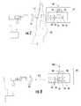
- FIG. 1is a schematic diagram of a first example embodiment of an RFID system 10 according to the present invention.
- RFID system 10includes an RFID-tag reader (“RFID reader”) 20 that includes signal generation/processing electronics (“reader electronics”) 22 operably connected to an antenna system (“reader antenna”) 26.
- RFID reader 20is adapted to generate a RF interrogation signal SI designed to interrogate an RFID tag 40 and to receive a RF tag signal ST from the RFID tag 40 .
- Interrogation signal SIalso serves to power the passive RFID tag 40 and so is also referred to herein as a "RF interrogation field.”
- RFID system 10is shown to include a plurality of passive switchable RFID tags 40 , which is shown attached to an item 44. Two items 44 and their corresponding RFID tags 40 are shown for the sake of illustration.
- RFID tag 40includes an RFID integrated circuit (IC) chip 56 operably coupled to a RF antenna system ("tag antenna") 60 .
- RFID IC chip 56includes a memory device 66 that stores information to be transmitted to RFID reader 20 via tag signal ST , and an energy storage unit 68 that stores energy for powering the chip.
- memory device 66stores information related to item 44 , such as the item serial number, item type, manufacturer, manufacturing date, installation date, location, lot number, performance parameters, identification of other items that relate to or that are connected to the item, etc.
- RFID IC chip 56Such information can be preloaded on RFID IC chip 56 upon manufacture or upon installation by writing the information to the RFID IC chip using an RFID reader. It is also anticipated that memory device 66 stores other information, such as information relating to the switch state of RFID tag 40 , as described below.
- RFID tag 40further includes additional wires 90 that electrically connect RFID IC chip 56 with an activation device.
- a switch 100such as a push-button switch is shown.
- Switch 100moves up and down, as shown by the double-ended arrow and that has two switch states.
- switch 100is engaged to establish a connection between wires 90 (as shown in the upper RFID tag in FIG. 1 )
- the switchis in the ON state (position).
- switch 100is engaged to interrupt the connection between wires 90 (such as shown in the lower RFID tag in FIG. 1 )
- the switchis in the OFF state (position).
- switch 100is designed so that a user needs to remain engaged with the switch so that it stays in the ON state. Otherwise, switch 100 remains in the OFF state.
- Information about switch-ON eventsis communicated from RFID tag 40 to RFID reader 20 via a switch-state signal SS .
- memory device 66is adapted to store information about the number of times switch 100 is placed in the ON state (i.e., "switch-ON events").
- Information relating to switch-ON eventscan be stored using, for example, a switch-state memory bit that goes to "1" when switch 100 is placed in the ON state but when switch-state signal SS is not yet generated, and that goes to "0" when switch-state signal SS is transmitted ON state
- the switch-state memory bitgoes from 0 to 1 regardless of the number of times the switch is placed in the ON state prior to switch-state signal SS being transmitted.
- RFID tag 40also includes a local energy storage device 110 electrically coupled to RFID IC chip 56 .
- Local energy storage device 110is in addition to (or replaces) chip-based energy storage unit 68 and in an example embodiment allows RFID tag 40 to store energy from interrogation signal SI even when the RFID tag switch 100 is in the OFF state.
- RFID reader 20is also preferably adapted to generate other RF signals that do not necessarily elicit RF tag signal ST but instead either elicit other types of RF signals (e.g., switch-state signal SS or another type of status signal), or that sets a condition within the RFID tag (e.g., a signal SR , discussed below, that sets or re-sets the switch-state memory bit in memory device 66 ).
- other types of RF signalse.g., switch-state signal SS or another type of status signal
- a condition within the RFID tage.g., a signal SR , discussed below, that sets or re-sets the switch-state memory bit in memory device 66 .
- RFID system 10includes a database unit 70 operably coupled to RFID reader 20, e.g., via a wireless connection 72 or a non-wireless connection 74, such as an optical fiber or wire-based connection.
- database unit 70may be incorporated directly into RFID reader 20.
- Database unit 70is adapted to store information relating to one or more RFID tags and/or its associated items 44 in order to facilitate identification, mapping, or other processing of information received from one or more RFID tags 40 .
- database unit 70includes information that correlates a unique identification number of an RFID tag to a particular plug and/or socket, to a particular component (such as a fiber optic cable assembly with one or more connectors), to other portions of the component (such as correlating a first connector of a fiber optic cable to a second connector, or grouping multiple adapters of a patch panel, etc.), to past and/or current mating components, and any other parameter, connection, association, or other information that a technician may want to know or record when working with and/or monitoring the one or more components.
- a unique identification number of an RFID tagto a particular plug and/or socket
- a particular componentsuch as a fiber optic cable assembly with one or more connectors
- other portions of the componentsuch as correlating a first connector of a fiber optic cable to a second connector, or grouping multiple adapters of a patch panel, etc.
- any other parameter, connection, association, or other informationthat a technician may want to know or record when working with and/or monitoring the one or more components.
- Reading distance D Ris determined based on a number of factors, including the relative strengths of the various signals from the RFID reader and the RFID tag, as well their relative antenna strengths and the frequency of the signals used.
- a userseeks to activate the item 44 by engaging switch 100, by grasping item 44 by hand.
- the user's handis placed in such a way that their hand 120 is inserted into the RF communication path 114 and thus blocks interrogation signals SI from RFID reader 20 from reaching RFID tag 40 .
- switch-state signal SSwould not be sent when RF communication between the RFID tag and RFID reader is re-established and adequate power is delivered to the RFID tag because the switch-ON event would not be recorded.
- the RFID tag 40when the user engages switch 100 to the ON state, the RFID tag 40 would continue to be powered by either the energy storage unit 68 or the local energy storage device 110, thereby allowing the memory device 66 to record this switch-change event, as described above.
- the switch-state memory bit in memory device 66remains at 1 regardless of how many times the user turns the switch ON and OFF prior to RFID tag 40 transmitting switch-state signal SS.
- RF communication path 114is no longer interrupted and RFID tag 40 is able to receive adequate power from interrogation signal SI from RF reader 20. Since the switch-state memory bit was set to 1, the RFID tag responds in a delayed fashion by sending switch-state signal SS to RFID reader 20. Where there is more than one RFID tag 40, the transmission and reception of switch-state signals SS from the various RFID tags is preferably carried out in an orderly manner, i.e., by avoiding interference with other RFID tags that may have also had their switches placed in the ON state during the same period. This is accomplished by using standard RFID communication algorithms.
- switch-state memory bit in memory device 66is set to 0. This is accomplished, for example, as illustrated in FIG. 4 by RFID reader 20 sending a reset signal SR once switch-state signal SS is received and processed.
- chip-based energy storage unit 68will be depleted of energy to the point that the RFID IC chip 56 cannot function properly. This would lead to the switch-ON memory bit being lost.
- RFID tag 40is also able to detect that it has completely lost power (using additional techniques such as described below), it would know that the state of the "switch-ON" memory bit was invalid and it would not switch-state memory bit transmit switch-state signal SS .
- local energy storage device 110is used for powering RFID IC chip 56 until RF communication between RFID reader 20 and RFID tag 40 is re-established and adequate power is received by the RFID tag.
- Energy storage device 110is charged by harvesting the power in RF interrogation signal(s) SI during a period of time prior to when RF communication between RFID reader 20 and RFID tag 40 was interrupted.
- Energy storage device 110is designed to power RFID IC chip 56 for a period of time longer than the typical time required by a user to maintain switch 100 in the ON state (e.g., 5-10 seconds or greater).
- energy storage device 110is or includes an electric capacitor or a long-life trickle-charge battery.
- RFID applicationsit may be desirable to avoid adding a local energy storage device 110 as described above due to size, cost and/or lifetime considerations.
- interruption in RF communication between RFID reader 20 and RFID tag 40due, for example, to the presence of the user's hand, inhibits RF power harvesting and causes the RFID IC chip to lose power after a short period of time, usually much less than 1 second. Consequently, the RFID IC chip 56 will be unable to actively detect if or when switch 100 is placed in the ON state.
- FIG. 5is a schematic diagram of an RFID tag 40 that includes or, is otherwise operably coupled to, a local memory device 150.
- the local memory device 150serves to record an activation event of item 44 and RFID tag 40.
- the activation eventis shown by the depressing of switch 100, item 44 may be activated in numerous ways, for example, by simply touching item 44.
- Local memory device 150provides a local memory storage function based on either mechanical, electrical or thermal effects, as described below.
- RFID IC chip 56is first powered by RF interrogation signal SI from RFID reader 20.
- the switch 100is OFF so that the local memory storage device 150 is set (or reset) to a state indicating that the switch has not yet been placed in the ON state.
- RF communication path 114 between RFID reader 20 and RF tag 40is then blocked, thereby interrupting RF communication and causing the RFID IC chip 56 to lose power within a short period of time - say, within about 4 seconds. As described above, this typically happens when the user puts their hand 120 between RFID reader 20 and RFID tag 40.
- RFID tag 40may receive some power via interrogation signal SI even when RF communication path 114 is blocked because the blockage may simply serve to attenuate the interrogation signal. However, RFID tag 40 needs to receive some threshold signal level adequate to power up RFID IC chip 56 so that it can properly operate. In this case, proper operation would entail sufficient energy to record an activation event to the local memory device 150, such that this event can be properly communicated to the RFID reader 20.
- An activation eventoccurs when the user then places switch 100 in the ON state.
- Local memory storage device 150is adapted so as to record and retain said activation information, namely information about switch 100 being in the ON state (i.e., "switch-ON" events).
- RF communication between RFID reader 20 and RFID tag 40is then re-established say by the user removing their hand 120 from item 44 or the RFID tag itself so that the RF communication path 114 is no longer blocked. This allows RFID tag 40 to receive interrogation signal SI and power up the RFID IC chip 56.
- the state of local memory storage device 150is interrogated by RFID reader 20 using a memory status interrogation signal SM to determine if switch 100 was placed in the ON state while RFID tag 40 was unpowered.
- switch-state signal SSis triggered by interrogation signal SI, which is normally used to elicit transmission of tag signal ST .
- switch-state signal SSis sent automatically as soon as RFID IC chip 56 is powered up and a switch-state memory bit value of 1 is detected.
- local memory storage device 150is reset to enable the detection of subsequent switch activations.
- local memory storage device 150is reset actively by RFID reader 20 sending a reset signal SR (as discussed above in connection with FIG. 4 ), or is reset passively by RFID IC chip or some other locally-induced reset initiation source.
- FIG. 9is a schematic diagram similar to FIG. 5 , illustrating another example embodiment of RFID system 10, wherein local memory storage device 150 is or includes a mechanical latch 160.
- Mechanical latch 160is mechanically coupled to switch 100 and is also optionally electrically coupled to RFID IC chip 56 via an electrical connection 154.
- mechanical latch 160is adapted to maintain switch 100 in the ON state, e.g., maintain an electrical connection between wires 90 after the user places the switch in the ON state.
- RFID IC chip 56regains power, it detects that switch 100 has been placed in the ON state directly via completion of the switch circuit and/or via separate electrical connection 154 .
- mechanical latch 160is designed to unlatch automatically after a certain period of time. This unlatching latency can be provided, for example, by the mechanical relaxation of a deformed or buckled member such as a beam or blister element. The relaxation time can be determined by material properties and geometry of the deformed element.
- mechanical latch 160includes a mechanical two-position rocker or slide switch (not shown). In this mechanical two-position rocker embodiment, the user manually moves the switch back to its original state before any subsequent switch is detected.
- mechanical latch 160is unlatched via a command (e.g., re-set signal SR ) from RFID reader 20 or RFID IC chip 56 that travels to the latch via electrical connection 154 .
- a commande.g., re-set signal SR
- electro-mechanical unlatching mechanismsuch as a solenoid-activated latch or a thermally-activated shape memory alloy, or a bi-metallic actuator. While the power levels required to activate such electro-mechanical actuators might seem high, energy harvested from interrogation signals SI can be stored in an optional local energy storage device 110 (e.g., a capacitor) to enable a rapid pulse discharge through the electro-mechanical actuator to unlatch the mechanical latch.
- mechanical latch 160is unlatched via flexure of a bi-metallic strip (not shown).
- the stripis designed to buckle into an unstable deformed state based on mechanical pressure from the user activating switch 100. Heat from the user's hand causes the bi-metallic strip to remain in the buckled state for a short period of time. After the bi-metallic strip cools, switch 100 returns to its non-depressed state via deflection of the bi-metallic strip.
- the thicknesses, specific heat capacities and thermal conductivities of materials in proximity to the bi-metallic stripare tuned to achieve a desired delay between the time the user removes their hand from switch 100 and the time the switch returns to its OFF (e.g., non-depressed) state.
- mechanical latch 160serves as the memory storage device 150 and further eliminates the need for a separate switch 100.
- the activation eventcauses the mechanical latch 160 to move from a first state to a second activated state and to remain in said second activated state.
- the RFID IC chip 56reads the position of the mechanical latch 160 and communicates that an activation event has occurred.
- FIG. 10is a schematic diagram similar to FIG. 9 , wherein local memory device 150 includes a discharge capacitor 170.
- discharge capacitor 170is connected in parallel between wires 90 that connect RFID IC chip 56 to switch 100.
- RFID IC chip 56is adapted to charge discharge capacitor 170 and to sense when the capacitor discharges.
- Capacitor 170can be implemented as a discrete electrical component external to RFID IC chip 56 and to RFID tag 40, as shown, can be external to the RFID IC chip but internal to RFID tag 40, or can be integrated onto the RFID IC chip.
- RFID IC chip 56is first powered up by a RF signal (e.g., interrogation signal SI ) from RFID reader 20, which also leads to discharge capacitor 170 being fully charged up.
- RF communication between RFID reader 20 and RFIG tag 40is then interrupted (e.g., by the user placing their hand around item 44 ). This causes RFID IC chip 56 to lose power within a short period of time (e.g., in 4 seconds or less). Discharge capacitor 170 remains charged during this period. The user then places switch 100 into the ON state, which closes the circuit and allows current to flow out of and discharge the discharge capacitor 170.
- the state of discharge capacitor 170is interrogated by RFID reader 20 to determine if switch 100 was placed in the ON state while RFID IC chip 56 was unpowered. This interrogation can be implemented via a separate memory-status interrogation signal SM, similar to that described above. After the state of discharge capacitor 170 is read, it is recharged to enable detection of a subsequent switch-ON event.
- discharge capacitor 170may serve as the memory storage device 150 and eliminate the need for a separate switch 100.
- the activation eventcauses the discharge capacitor 170 to move from a first charged state to a second fully-discharged state.
- the RFID IC chip 56reads the condition of the discharge capacitor 170 and if the discharge capacitor 170 is in the fully discharged state, communicates that an activation event has occurred.
- RFID IC chip 56Since discharge capacitor 170 eventually discharges on its own even if the switch 100 is not placed in the ON state, RFID IC chip 56 needs to periodically check the charge on discharge capacitor 170. If discharge capacitor 170 is only partially discharged (e.g., the amount of charge falls below a charge threshold level), RFID IC chip 56 recharges the capacitor without registering a switch-ON event. If discharge capacitor 170 is completely discharged, RFID IC chip 56 registers a switch-ON event and then waits for subsequent RFID reader interrogation (via status signal SS ) regarding the switch-ON event. This situation corresponds, for example, to the case where the user's hand 120 did not sufficiently block interrogation signal SI while the user was engaging switch 100 .
- discharge capacitor 170presents a challenge in cases where RFID IC chip 56 is unpowered for a long period of time, i.e., greater than the time required for discharge capacitor 170 to discharge on its own if switch 100 is not placed in the ON state. In this case, RFID IC chip 56 is unable to implement the discharge capacitor checking process described immediately above. Discharge capacitor 170 will eventually discharge. When RFID IC chip 56 later regains power, it will find that the discharge capacitor has discharged and would possibly incorrectly infer that the discharge was the result of switch 100 being placed in the ON state when the RFID IC chip was unpowered.
- local memory device 150includes a second reference capacitor 174 physically identical to discharge capacitor 170 and electrically coupled to RFID IC chip 56.
- Reference capacitor 174can be provided in a number of locations, such as on RFID IC chip 56 or as an external discrete component such as shown in FIG. 11 .
- Reference capacitor 174is charged each time discharge capacitor 170 is charged. As both capacitors are identical (or substantially so) they discharge at approximately the same rate if switch 100 is not in the ON state.
- Reference capacitor 174is used to detect the condition where the RFID IC chip 56 has been unpowered for a sufficient period of time for discharge capacitor 170 to discharge completely.
- RFID IC chip 56When RFID IC chip 56 is re-powered after a power disruption, the state of reference capacitor 174 is examined. If reference capacitor 174 is discharged, RFID IC chip 56 knows it has been unpowered for a long period of time and therefore ignores the state of discharge capacitor 170 as an indicator of a switch-ON event. On the other hand, if reference capacitor 174 is sufficiently charged, then RFID IC chip 56 knows that the charge state of discharge capacitor 170 is valid, and responds following the switch-ON protocol described above.
- the above-described methods of detecting and preventing erroneous switch-ON eventsare important because loss of power events can occur simultaneously for many RFID IC chips 56 in different RFID tags 40 when interrogation signals SI from RFID reader 20 are even temporarily interrupted. Detecting erroneous switch-ON events prevent RFID reader 20 from being flooded with switch-state signals SS that represent invalid switch-ON events following simultaneous power loss for a large number of such RFID tags 40 that reside within the read distance of the RFID reader.
- FIG. 12is a schematic diagram similar to FIG. 11 , illustrating an example embodiment wherein local memory device 150 includes a temperature sensor 180 adapted to detect a temperature change due to the proximity of a user's hand 120 to RFID tag 40 or to item 44 to which the RFID tag is attached.
- temperature sensor 180is implemented on or near the surface of item 44 and electrically interfaced to RFID IC chip 56.
- temperature sensor 180is integrated with RFID IC chip 56.
- temperature sensor 180resides within RFID tag 40 but remains external to RFID IC chip 56. When the user holds item 44 in their bare hand 120, the item rapidly heats up by several degrees C, particularly when item 44 is relatively small and has a substantial heat capacity. This temperature change is then detected by temperature sensor 180, which provides a temperature signal ST to the RFID IC chip.
- RFID IC chip 56is initially powered by interrogation signal SI from RFID reader 20.
- RFID IC chip 56has a dedicated memory location in memory device 66 that is used to flag a "switch-ON event.”
- the corresponding switch-event memory bitis initially set to 0.
- the userthen places their hand around item 44, which interrupts RF communication between RFID reader 20 and RFID tag 40, causing RFID IC chip 56 to lose power within a short period of time, e.g., 4 seconds or less.
- Item 44also begins to increase in temperature due to the transfer of heat 184 from the user's hand 120 to the item.
- RFID IC chip 56interprets a rate of change of temperature that exceeds a predefined threshold value as a switch-ON event and sets the switch-ON event memory bit to 1. This switch-ON event may or may not be detected by RFID reader 20, depending on the amount of time RFID IC chip 56 remains powered.
- the userthen removes their hand 120 from the item 44, which re-establishes RF communication between RFID reader 20 and RFID tag 40.
- Thisallows RFID IC chip 56 to regain power from interrogation signals SI, while also allowing item 44 to cool down by radiation heat 186.
- the temperature of item 44is measured periodically over time by temperature sensor 180. If the rate of change of the temperature of the item decreases by more than a predefined threshold value, RFID IC chip 56 detects a switch-ON event and sets the switch-ON event bit to 1.
- RFID reader 20then interrogates all RFID tags 40 in the vicinity to elicit switch-state signals SS to identify those RFID IC chips 56 that detected a switch-ON event and that set the corresponding switch-state memory bit in the associated memory device 66 to 1.
- the RFID tagssimply transmit their switch-state signal SS once the RFID tag is powered up and a switch-state memory bit value of 1 is detected.
- RFID reader 20receives the switch-state signals SS from one or more of the RFID tags 40 in its read range and responds by transmitting a reset signal SR that resets the switch-state memory bit to 0 ( FIG. 14 ).
- the rate of temperature change of item 44can be modified or controlled by adjusting the thicknesses, specific heat capacities and thermal conductivities of materials that make up the item.
- temperature sensor 180may serve as the memory storage device 150 and eliminate the need for a separate switch 100.
- the activation eventcauses the temperature sensor 180 to rapidly increase in temperature, moving from a first temperature state to a second temperature state.
- the source of heat 184is removed when the user removes his or her hand 120 from the item 44, this also re-establishes RF communication between RFID reader 20 and RFID tag 40.
- Thisallows RFID IC chip 56 to regain power from interrogation signals SI, while also allowing item 44 to cool down by radiation heat 186.
- the temperature of item 44is measured periodically over time by temperature sensor 180. If the rate of change of the temperature of the item decreases by more than a predefined threshold value, RFID IC chip 56 detects an activation event has occurred and communicates this information to RFID tag 40 .
Landscapes
- Engineering & Computer Science (AREA)
- Computer Hardware Design (AREA)
- Microelectronics & Electronic Packaging (AREA)
- Physics & Mathematics (AREA)
- General Physics & Mathematics (AREA)
- Theoretical Computer Science (AREA)
- Electromagnetism (AREA)
- Computer Networks & Wireless Communication (AREA)
- Near-Field Transmission Systems (AREA)
Description
- The present invention relates generally to radio-frequency identification (RFID) technology, and in particular relates to RFID-based systems and methods for detecting that a condition has occurred in an RFID tag even when the RFID tag is not powered, by storing and managing power in RFID tags.
- Radio-frequency identification (RFID) is a remote recognition technique that utilizes RFID tags having information stored therein, usually in an integrated circuit (IC). The stored information is retrievable via RF communication between the RFID tag and an RFID tag reader. Certain RFID systems utilize hand-held RFID readers that when brought sufficiently close to an RFID tag are able to read an RFID tag signal either emitted by or backscattered from the tag. RFID systems are used for a variety of applications, including inventory management and product tracking in a number of different industries, as well as in libraries and hospitals.
- RFID tags generally come in three varieties: passive, semi-passive, and active. Passive RFID tags have no energy or power source of their own and operate by harvesting energy from the RF signal (field) generated by the RFID-tag reader. Passive tags communicate back to the reader by modulating and back-scattering the RF signal from the RF reader. Semi-passive RFID tags communicate to the reader in the same way via modulation of the back-scattered reader RF signal, but they do not rely on harvesting energy from the reader field to power the RFID tag IC. Instead, semi-passive tags generally have their own power source, usually in the form of one or more batteries. Since the amount of power harvested by a passive tag usually limits its maximum distance from the reader antenna, semi-passive RFID tags usually have significantly greater read ranges than passive tags. Active tags also have a power source such as a battery that not only powers the RFID tag IC but that can also actively generate and transmits radiation to the RFID reader.
- RFID tags can be designed to operate at different RF frequencies. At low frequencies (e.g., 100-130 KHz s) RFID tags often communicate via mutual inductance coupling between an RFID-reader coil antenna and an RFID-tag coil antenna. At these frequencies, the RFID reader's RF signal is not strongly absorbed by water. Since the user's hand is primarily composed of water, this means that at low RF frequencies the RF signal can penetrate the user's hand and enable two-way communication between the RFID tag and the RFID reader.
- This low frequency inductance coupling approach is practical as long as the distance between the tag and the reader is a fraction of the wavelength of the RF signal. In typical low frequency RFID tag applications, the required separation between the RFID tag and the RFID reader (i.e., the "read distance") must be less than 1 m. This small separation is not suitable for many applications involving the RFID identification of hand-held items. In particular, the separation distance between RFID tags and RFID readers in typical item-identification applications within telecommunications data centers is expected to be 1 m to 3 m. Therefore, the low frequency RFID tag solution is not a practical approach for this and other such applications.
- RFID tags designed to operate at higher frequencies (e.g., ultra-high frequencies of 900 MHz or greater) typically operate by the RFID tag capturing far-field radiation from the RFID reader antenna transmission using a local monopole, dipole or modified dipole antenna (e.g., a "squiggle antenna").
- The electric signal formed by the RFID tag antenna is processed by a rectifier circuit in the RFID tag's IC chip, yielding energy that powers the rest of the IC chip and enables the IC chip to transmit a return signal to the RFID reader. As mentioned above, communication with the RFID reader is often via backscatter modulation of the RFID reader signal rather than by independent RF signal transmission from the RFID tag.
- Ultra-high-frequency RFID tags can communicate with RFID readers at much greater read distances (e.g., 5 to 10 m) than low frequency RFID tags (1 m or less). Ultra-high-frequency RFID tags are thus better suited for applications involving the RFID identification of hand-held items.
- A problem with using ultra-high frequency RFID tags for the identification of hand-held items arises due to the strong absorption of high-frequency RF signal power by water. When a user places their hand around an item with an RFID tag just prior to engaging, water in the user's hand attenuates the reader's RF signal when the hand blocks the RF communication path. Even in cases where the user's hand only partially blocks the RF communication path, it can still significantly reduce the RF signal strength. In this situation, the RFID tag may not receive sufficient energy to power its internal circuitry. Likewise, the RFID tag's response to the RFID reader may be impeded by the presence of the user's hand.
- In the case where the RFID tag does not receive adequate power to operate, no signal is communicated to the RFID tag reader. When the user removes their hand from the item and disengages the switch, then the RFID tag once again receives RF power from the RFID reader and powers up. An approach is described that enables the RFID tag reader to detect when an event has occurs at the RFID tag during periods when the power to the RFID tag has been interrupted.
US 2008/0100456 A1 discloses condition RFID tags associated with condition responsive devices. The condition responsive devices are responsive to one or more conditions and/or change in condition such as a state of contact, electrical contact closure, temperature, pressure, humidity, light, or capacitance (and/or impedance).The condition responsive device may be user-operated, for example by pressing a push button or connecting or disconnecting a plug from a socket, or the condition responsive device may be a passively operated sensor, or both could be employed together. Further, the condition and/or change in condition indicated by the condition responsive device may permit or preclude operation of a given RFID transponder. Alternatively, such condition and/or change in condition may simply be registered and/or reported by the RFID transponder without altering the operational status of the RFID transponder.WO 2009/091888 A1 discloses patch cable connectors, adapters, patch panels and rack-mounted housings, electronics and optical/electrical equipment, etc. provided with one or more RFID tags. The RFID tags may include a switch (e.g., a push-button-type switch) that provides a latchable signal to the integrated circuit (IC) as an IC input. For example, the technician can activate the RFID tag to generate a signal representative of the type of component to which the RFID tag is attached, and where the component is to be connected.- One aspect of the invention is an RFID tag for use with an RFID reader that transmits RF signals to the RFID tag via a RF communication path. The RFID tag includes an RFID integrated circuit (IC) chip electrically coupled to an RF antenna system and adapted to be externally powered by the RF signals. The RFID tag also includes an energy storage device operably coupled to the RFID IC chip and adapted to store energy from the RF signals. The RFID tag also includes a memory device that is powered by the energy device so as to store switch-state information when the RFID IC chip is inadequately externally powered so that when the RFID IC chip is adequately externally powered it causes the tag antenna system to transmit an RF activation signal representative of the stored activation information.
- Certain passive RFID tags have a switch (e.g., a push-button) that activates the RFID tag and/or that serves to program the RFID tag in some manner. In the latter instance, such programming may include setting the RFID tag to a particular operating state and/or inputting information into the tag. For example, the switch may be used to store information indicating that a person has handled the RFID tag. The switch may also be used to set a flag or a bit in the RFID tag's memory that gives the tag a special status. For example, a certain flag or bit can be selected that allows the RFID tag to communicate with an RFID reader that generates a particular type of interrogation signal.
- When a user engages the RFID tag switch, for example, when the user depresses a push-button switch integral to a hand-held device, an RFID integrated circuit chip detects the switch contact closure event and relays this information along with an identifying ID code to a nearby RFID reader. The RFID reader transfers this information to a data processing unit (i.e. a data management software system) for additional processing. Based on the tag ID code, the software system presents the user with additional information via a user interface (i.e., a display on a hand-held unit). This additional information can include, for example the name of the item, its location, manufacturing date or previously measured performance data.
- The typical RFID tag is attached to an item and contains information related to the item. When a user grasps the item, there is a high likelihood that the user's hand will at least partially block the RF communication path between the RFID reader antenna and the RFID tag antenna. The amount of RF power absorbed by the user's hand depends on the frequency of the RF signal and the strength of the RF signal and determines whether RF communication between the RFID tag and the RFID reader is interrupted.
- Additional features and advantages of the invention will be set forth in the detailed description which follows, and in part will be readily apparent to those skilled in the art from that description or recognized by practicing the invention as described herein, including the detailed description which follows, the claims, as well as the appended drawings.
- It is to be understood that both the foregoing general description and the following detailed description present embodiments of the invention, and are intended to provide an overview or framework for understanding the nature and character of the invention as it is claimed. The accompanying drawings are included to provide a further understanding of the invention, and are incorporated into and constitute a part of this specification. The drawings illustrate various embodiments of the invention, and together with the description serve to explain the principles and operations of the invention.
FIG. 1 is a schematic diagram of a first example embodiment of an RFID system that includes a switchable RFID tag that is able to remain powered when the RF communication path between the RFID reader and the RFID tag is interrupted;FIG. 2 is a schematic diagram of the RFID tag ofFIG. 1 , wherein a user's hand interrupts the RF communication path when the user engages the RFID-tag switch;FIG. 3 is a schematic diagram similar toFIG. 1 , illustrating a situation where the user's hand no longer interrupts the RF communication path but wherein the RFID tag still transmits a switch-state signal even when the RFID-tag switch is in the OFF state;FIG. 4 is a schematic diagram similar toFIG. 1 , wherein the RFID reader sends a reset signal to the RFID tag to reset the switch-state memory bit in the RFID tag's memory device;FIG. 5 is a schematic diagram of an example embodiment of an RFID tag similar to that shown inFIG. 1 , wherein the RFID tag includes a local memory device for storing information regarding switch-ON events while the RFID tag is unpowered;FIG. 6 is a schematic diagram similar to that ofFIG. 1 but including the RFID tag ofFIG. 5 , illustrating normal operation of the RFID tag when the RF communication path is uninterrupted so that the RFID tag is powered by the interrogation signal from the RFID reader;FIG. 7 is the schematic diagram ofFIG. 6 , but with a user's hand blocking the RF communication path so that the RFID tag does not receive power from the RFID reader's interrogation signals;FIG. 8 is the schematic diagram ofFIG. 6 , but with the RFID reader sending a memory status signal to determine whether the switch was placed in the ON state while the RFID tag was unpowered;FIG. 9 is a schematic diagram similar toFIG. 5 , illustrating an embodiment wherein the local memory device includes a mechanical latch mechanically coupled to the RFID-tag switch;FIG. 10 is a schematic diagram similar toFIG. 9 , illustrating an example embodiment of an electrical local memory device that includes a discharge capacitor;FIG. 11 is a schematic diagram similar toFIG. 10 , illustrating an example embodiment wherein the electrical local memory device further includes a reference capacitor;FIG. 12 is a schematic diagram similar toFIG. 5 , illustrating an example embodiment wherein a temperature sensor serves as a switch;FIG. 13 is a schematic diagram similar toFIG. 12 , illustrating how a user's hand serves to block the RF communication path and to also heat the item and thus the RFID tag attached thereto, so that the increased temperature of the item is recorded by the temperature sensor;FIG.14 is a schematic diagram similar toFIG. 13 , but with the user's hand removed, illustrating how the RF communication path is restored and how the item and RFID tag cools down once the user's hand is removed;- Several exemplary embodiments of the invention are described in greater detail, with reference to the accompanying drawings. Whenever possible, the same reference numerals are used throughout the drawings to refer to the same or like parts.
- As discussed above, a prior-art passive RFID tag is unable to store power from a RF signal from an RFID-tag reader when RF communication (and hence power) between the RFID tag and the RFID-tag reader is interrupted. This can prevent switching events from being recorded by the RFID-tag reader. Several different example embodiments of RFID systems and methods that address problems associated with recording RFID-tag switching events are set forth below.
FIG. 1 is a schematic diagram of a first example embodiment of anRFID system 10 according to the present invention.RFID system 10 includes an RFID-tag reader ("RFID reader")20 that includes signal generation/processing electronics ("reader electronics")22 operably connected to an antenna system ("reader antenna")26.RFID reader 20 is adapted to generate a RF interrogation signalSI designed to interrogate anRFID tag 40 and to receive a RF tag signalST from theRFID tag 40. Interrogation signalSI also serves to power thepassive RFID tag 40 and so is also referred to herein as a "RF interrogation field."- In this embodiment,
RFID system 10 is shown to include a plurality of passive switchable RFID tags40, which is shown attached to anitem 44. Twoitems 44 and their corresponding RFID tags40 are shown for the sake of illustration.RFID tag 40 includes an RFID integrated circuit (IC)chip 56 operably coupled to a RF antenna system ("tag antenna")60.RFID IC chip 56 includes amemory device 66 that stores information to be transmitted toRFID reader 20 via tag signalST, and anenergy storage unit 68 that stores energy for powering the chip. In this first example embodiment,memory device 66 stores information related toitem 44, such as the item serial number, item type, manufacturer, manufacturing date, installation date, location, lot number, performance parameters, identification of other items that relate to or that are connected to the item, etc. Such information can be preloaded onRFID IC chip 56 upon manufacture or upon installation by writing the information to the RFID IC chip using an RFID reader. It is also anticipated thatmemory device 66 stores other information, such as information relating to the switch state ofRFID tag 40, as described below. RFID tag 40 further includesadditional wires 90 that electrically connectRFID IC chip 56 with an activation device. As an example of such an activation device aswitch 100, such as a push-button switch is shown. Switch100 moves up and down, as shown by the double-ended arrow and that has two switch states. Whenswitch 100 is engaged to establish a connection between wires90 (as shown in the upper RFID tag inFIG. 1 ), the switch is in the ON state (position). Similarly, whenswitch 100 is engaged to interrupt the connection between wires90 (such as shown in the lower RFID tag inFIG. 1 ), the switch is in the OFF state (position). In an example embodiment,switch 100 is designed so that a user needs to remain engaged with the switch so that it stays in the ON state. Otherwise, switch100 remains in the OFF state. Information about switch-ON events (when the switch has been depressed) is communicated fromRFID tag 40 toRFID reader 20 via a switch-state signalSS.- Furthermore, in an example
embodiment memory device 66 is adapted to store information about the number of times switch100 is placed in the ON state (i.e., "switch-ON events"). Information relating to switch-ON events can be stored using, for example, a switch-state memory bit that goes to "1" whenswitch 100 is placed in the ON state but when switch-state signalSS is not yet generated, and that goes to "0" when switch-state signalSS is transmitted ON state In an example embodiment, the switch-state memory bit goes from 0 to 1 regardless of the number of times the switch is placed in the ON state prior to switch-state signalSS being transmitted. - In said first example embodiment,
RFID tag 40 also includes a localenergy storage device 110 electrically coupled toRFID IC chip 56. Localenergy storage device 110 is in addition to (or replaces) chip-basedenergy storage unit 68 and in an example embodiment allowsRFID tag 40 to store energy from interrogation signalSI even when theRFID tag switch 100 is in the OFF state. - As discussed in greater detail below, in addition to interrogation signalSI,
RFID reader 20 is also preferably adapted to generate other RF signals that do not necessarily elicit RF tag signalST but instead either elicit other types of RF signals (e.g., switch-state signalSS or another type of status signal), or that sets a condition within the RFID tag (e.g., a signalSR, discussed below, that sets or re-sets the switch-state memory bit in memory device66). - In said first example,
RFID system 10 includes adatabase unit 70 operably coupled toRFID reader 20, e.g., via awireless connection 72 or anon-wireless connection 74, such as an optical fiber or wire-based connection. In a further embodiment,database unit 70 may be incorporated directly intoRFID reader 20.Database unit 70 is adapted to store information relating to one or more RFID tags and/or its associateditems 44 in order to facilitate identification, mapping, or other processing of information received from one or more RFID tags40. In a more specific example embodiment relating to managing optical fiber communication systems and the associated items that make up such systems,database unit 70 includes information that correlates a unique identification number of an RFID tag to a particular plug and/or socket, to a particular component (such as a fiber optic cable assembly with one or more connectors), to other portions of the component (such as correlating a first connector of a fiber optic cable to a second connector, or grouping multiple adapters of a patch panel, etc.), to past and/or current mating components, and any other parameter, connection, association, or other information that a technician may want to know or record when working with and/or monitoring the one or more components. RFID reader 20 andRFID tag 40 communicate over aRF communication path 114 when the two are within the reading distanceDR of each other (seeFIG. 3 , introduced and discussed below). Reading distanceDR is determined based on a number of factors, including the relative strengths of the various signals from the RFID reader and the RFID tag, as well their relative antenna strengths and the frequency of the signals used.- With reference to
FIG. 2 , in the operation ofRFID system 10 ofFIG. 1 , a user seeks to activate theitem 44 by engagingswitch 100, by graspingitem 44 by hand. As shown inFIG. 2 , it is highly likely that in so engaging theswitch 100, the user's hand is placed in such a way that theirhand 120 is inserted into theRF communication path 114 and thus blocks interrogation signalsSI fromRFID reader 20 from reachingRFID tag 40. This prevents the RFID tag from receiving adequate power to operate, which means that when the user places switch100 to the ON state,RFID tag 40 does not have sufficient power to transmit switch-state signalSS. Normally, if the user were to allowswitch 100 to return to the OFF state, then switch-state signalSS would not be sent when RF communication between the RFID tag and RFID reader is re-established and adequate power is delivered to the RFID tag because the switch-ON event would not be recorded. - However, in the instant embodiment, when the user engages
switch 100 to the ON state, theRFID tag 40 would continue to be powered by either theenergy storage unit 68 or the localenergy storage device 110, thereby allowing thememory device 66 to record this switch-change event, as described above. The switch-state memory bit inmemory device 66 remains at 1 regardless of how many times the user turns the switch ON and OFF prior toRFID tag 40 transmitting switch-state signalSS. - With reference now to
FIG. 3 , after the user removes theirhand 120,RF communication path 114 is no longer interrupted andRFID tag 40 is able to receive adequate power from interrogation signalSI fromRF reader 20. Since the switch-state memory bit was set to 1, the RFID tag responds in a delayed fashion by sending switch-state signal SS toRFID reader 20. Where there is more than oneRFID tag 40, the transmission and reception of switch-state signalsSS from the various RFID tags is preferably carried out in an orderly manner, i.e., by avoiding interference with other RFID tags that may have also had their switches placed in the ON state during the same period. This is accomplished by using standard RFID communication algorithms. - After switch-state signalSS is received and processed by the RFID reader, the switch-state memory bit in
memory device 66 is set to 0. This is accomplished, for example, as illustrated inFIG. 4 byRFID reader 20 sending a reset signalSR once switch-state signal SS is received and processed. - If the user were to hold their
hand 120 in a position that blocks theRF communication path 114 betweenRFID reader 20 andRFID tag 40 for a sufficiently long time, chip-basedenergy storage unit 68 will be depleted of energy to the point that theRFID IC chip 56 cannot function properly. This would lead to the switch-ON memory bit being lost. However, ifRFID tag 40 is also able to detect that it has completely lost power (using additional techniques such as described below), it would know that the state of the "switch-ON" memory bit was invalid and it would not switch-state memory bit transmit switch-state signalSS. - Accordingly, in said first example embodiment, local
energy storage device 110 is used for poweringRFID IC chip 56 until RF communication betweenRFID reader 20 andRFID tag 40 is re-established and adequate power is received by the RFID tag.Energy storage device 110 is charged by harvesting the power in RF interrogation signal(s)SI during a period of time prior to when RF communication betweenRFID reader 20 andRFID tag 40 was interrupted.Energy storage device 110 is designed to powerRFID IC chip 56 for a period of time longer than the typical time required by a user to maintainswitch 100 in the ON state (e.g., 5-10 seconds or greater). In an example embodiment,energy storage device 110 is or includes an electric capacitor or a long-life trickle-charge battery. - In some RFID applications it may be desirable to avoid adding a local
energy storage device 110 as described above due to size, cost and/or lifetime considerations. In this case, interruption in RF communication betweenRFID reader 20 andRFID tag 40 due, for example, to the presence of the user's hand, inhibits RF power harvesting and causes the RFID IC chip to lose power after a short period of time, usually much less than 1 second. Consequently, theRFID IC chip 56 will be unable to actively detect if or whenswitch 100 is placed in the ON state. - In a second embodiment,
FIG. 5 is a schematic diagram of anRFID tag 40 that includes or, is otherwise operably coupled to, alocal memory device 150. Thelocal memory device 150 serves to record an activation event ofitem 44 andRFID tag 40. Although in this embodiment, the activation event is shown by the depressing ofswitch 100,item 44 may be activated in numerous ways, for example, by simply touchingitem 44.Local memory device 150 provides a local memory storage function based on either mechanical, electrical or thermal effects, as described below. - Regardless of the type of
local memory device 150 used, the general operation ofRFID system 10 that usesRFID tag 40 ofFIG. 5 is as follows. With reference toFIG. 6 ,RFID IC chip 56 is first powered by RF interrogation signalSI fromRFID reader 20. At this point, theswitch 100 is OFF so that the localmemory storage device 150 is set (or reset) to a state indicating that the switch has not yet been placed in the ON state. Next, with reference toFIG. 7 ,RF communication path 114 betweenRFID reader 20 andRF tag 40 is then blocked, thereby interrupting RF communication and causing theRFID IC chip 56 to lose power within a short period of time - say, within about 4 seconds. As described above, this typically happens when the user puts theirhand 120 betweenRFID reader 20 andRFID tag 40. It should be noted thatRFID tag 40 may receive some power via interrogation signal SI even whenRF communication path 114 is blocked because the blockage may simply serve to attenuate the interrogation signal. However,RFID tag 40 needs to receive some threshold signal level adequate to power upRFID IC chip 56 so that it can properly operate. In this case, proper operation would entail sufficient energy to record an activation event to thelocal memory device 150, such that this event can be properly communicated to theRFID reader 20. - An activation event occurs when the user then places switch100 in the ON state. Local
memory storage device 150 is adapted so as to record and retain said activation information, namely information aboutswitch 100 being in the ON state (i.e., "switch-ON" events). RF communication betweenRFID reader 20 andRFID tag 40 is then re-established say by the user removing theirhand 120 fromitem 44 or the RFID tag itself so that theRF communication path 114 is no longer blocked. This allowsRFID tag 40 to receive interrogation signalSI and power up theRFID IC chip 56. - After
RFID IC chip 56 regains power, then with reference toFIG. 8 , in an example embodiment the state of localmemory storage device 150 is interrogated byRFID reader 20 using a memory status interrogation signalSM to determine ifswitch 100 was placed in the ON state whileRFID tag 40 was unpowered. In another example embodiment, switch-state signalSS is triggered by interrogation signalSI, which is normally used to elicit transmission of tag signalST. In another example embodiment, switch-state signalSS is sent automatically as soon asRFID IC chip 56 is powered up and a switch-state memory bit value of 1 is detected. - Once switch-state signalSS is sent, local
memory storage device 150 is reset to enable the detection of subsequent switch activations. In an example embodiment, localmemory storage device 150 is reset actively byRFID reader 20 sending a reset signalSR (as discussed above in connection withFIG. 4 ), or is reset passively by RFID IC chip or some other locally-induced reset initiation source. - Three different example embodiments for implementing local
memory storage device 150 are described immediately below. FIG. 9 is a schematic diagram similar toFIG. 5 , illustrating another example embodiment ofRFID system 10, wherein localmemory storage device 150 is or includes amechanical latch 160.Mechanical latch 160 is mechanically coupled to switch100 and is also optionally electrically coupled toRFID IC chip 56 via anelectrical connection 154. In one embodiment, as shown inFIG. 9 ,mechanical latch 160 is adapted to maintainswitch 100 in the ON state, e.g., maintain an electrical connection betweenwires 90 after the user places the switch in the ON state. WhenRFID IC chip 56 regains power, it detects thatswitch 100 has been placed in the ON state directly via completion of the switch circuit and/or via separateelectrical connection 154.- Using this mechanical approach, it is important to unlatch
mechanical latch 160 afterRFID IC chip 56 has responded to interrogation signalSI fromRFID reader 20. This unlatching operation can be implemented in a number of ways. In a first example embodiment,mechanical latch 160 is designed to unlatch automatically after a certain period of time. This unlatching latency can be provided, for example, by the mechanical relaxation of a deformed or buckled member such as a beam or blister element. The relaxation time can be determined by material properties and geometry of the deformed element. In another example embodiment,mechanical latch 160 includes a mechanical two-position rocker or slide switch (not shown). In this mechanical two-position rocker embodiment, the user manually moves the switch back to its original state before any subsequent switch is detected. - In another example embodiment,
mechanical latch 160 is unlatched via a command (e.g., re-set signalSR) fromRFID reader 20 orRFID IC chip 56 that travels to the latch viaelectrical connection 154. This approach requires an electro-mechanical unlatching mechanism, such as a solenoid-activated latch or a thermally-activated shape memory alloy, or a bi-metallic actuator. While the power levels required to activate such electro-mechanical actuators might seem high, energy harvested from interrogation signalsSI can be stored in an optional local energy storage device110 (e.g., a capacitor) to enable a rapid pulse discharge through the electro-mechanical actuator to unlatch the mechanical latch. - In another example embodiment,
mechanical latch 160 is unlatched via flexure of a bi-metallic strip (not shown). The strip is designed to buckle into an unstable deformed state based on mechanical pressure from theuser activating switch 100. Heat from the user's hand causes the bi-metallic strip to remain in the buckled state for a short period of time. After the bi-metallic strip cools, switch100 returns to its non-depressed state via deflection of the bi-metallic strip. The thicknesses, specific heat capacities and thermal conductivities of materials in proximity to the bi-metallic strip are tuned to achieve a desired delay between the time the user removes their hand fromswitch 100 and the time the switch returns to its OFF (e.g., non-depressed) state. - In another example embodiment,
mechanical latch 160 serves as thememory storage device 150 and further eliminates the need for aseparate switch 100. In such an embodiment, the activation event causes themechanical latch 160 to move from a first state to a second activated state and to remain in said second activated state. Hence, once power is restored to theRFID IC chip 56 from theRFID reader 20, theRFID IC chip 56 reads the position of themechanical latch 160 and communicates that an activation event has occurred. FIG. 10 is a schematic diagram similar toFIG. 9 , whereinlocal memory device 150 includes adischarge capacitor 170. In an example embodiment,discharge capacitor 170 is connected in parallel betweenwires 90 that connectRFID IC chip 56 to switch100.RFID IC chip 56 is adapted to chargedischarge capacitor 170 and to sense when the capacitor discharges.Capacitor 170 can be implemented as a discrete electrical component external toRFID IC chip 56 and toRFID tag 40, as shown, can be external to the RFID IC chip but internal toRFID tag 40, or can be integrated onto the RFID IC chip.- In an example embodiment of the operation of
local memory device 150 ofFIG. 10 ,RFID IC chip 56 is first powered up by a RF signal (e.g., interrogation signalSI) fromRFID reader 20, which also leads to dischargecapacitor 170 being fully charged up. RF communication betweenRFID reader 20 andRFIG tag 40 is then interrupted (e.g., by the user placing their hand around item44). This causesRFID IC chip 56 to lose power within a short period of time (e.g., in 4 seconds or less).Discharge capacitor 170 remains charged during this period. The user then places switch100 into the ON state, which closes the circuit and allows current to flow out of and discharge thedischarge capacitor 170. - The user then removes their hand from the
item 44, which re-establishes RF communication betweenRFID reader 20 andRFID tag 40. This allowsRFID IC chip 56 to receive interrogation signalSI and use this signal to regain power. AfterRFID IC chip 56 regains power, the state ofdischarge capacitor 170 is interrogated byRFID reader 20 to determine ifswitch 100 was placed in the ON state whileRFID IC chip 56 was unpowered. This interrogation can be implemented via a separate memory-status interrogation signalSM, similar to that described above. After the state ofdischarge capacitor 170 is read, it is recharged to enable detection of a subsequent switch-ON event. - As is now clear to the reader,
discharge capacitor 170 may serve as thememory storage device 150 and eliminate the need for aseparate switch 100. In such an embodiment, the activation event causes thedischarge capacitor 170 to move from a first charged state to a second fully-discharged state. Once power is restored to theRFID IC chip 56 from theRFID reader 20, theRFID IC chip 56 reads the condition of thedischarge capacitor 170 and if thedischarge capacitor 170 is in the fully discharged state, communicates that an activation event has occurred. - Since
discharge capacitor 170 eventually discharges on its own even if theswitch 100 is not placed in the ON state,RFID IC chip 56 needs to periodically check the charge ondischarge capacitor 170. Ifdischarge capacitor 170 is only partially discharged (e.g., the amount of charge falls below a charge threshold level),RFID IC chip 56 recharges the capacitor without registering a switch-ON event. Ifdischarge capacitor 170 is completely discharged,RFID IC chip 56 registers a switch-ON event and then waits for subsequent RFID reader interrogation (via status signalSS) regarding the switch-ON event. This situation corresponds, for example, to the case where the user'shand 120 did not sufficiently block interrogation signalSI while the user was engagingswitch 100. - The discharge of
discharge capacitor 170 presents a challenge in cases whereRFID IC chip 56 is unpowered for a long period of time, i.e., greater than the time required fordischarge capacitor 170 to discharge on its own ifswitch 100 is not placed in the ON state. In this case,RFID IC chip 56 is unable to implement the discharge capacitor checking process described immediately above.Discharge capacitor 170 will eventually discharge. WhenRFID IC chip 56 later regains power, it will find that the discharge capacitor has discharged and would possibly incorrectly infer that the discharge was the result ofswitch 100 being placed in the ON state when the RFID IC chip was unpowered. - With reference to
FIG. 11 , in an example embodiment directed toward preventing erroneously inferring a switch-ON event,local memory device 150 includes asecond reference capacitor 174 physically identical to dischargecapacitor 170 and electrically coupled toRFID IC chip 56.Reference capacitor 174 can be provided in a number of locations, such as onRFID IC chip 56 or as an external discrete component such as shown inFIG. 11 .Reference capacitor 174 is charged eachtime discharge capacitor 170 is charged. As both capacitors are identical (or substantially so) they discharge at approximately the same rate ifswitch 100 is not in the ON state.Reference capacitor 174 is used to detect the condition where theRFID IC chip 56 has been unpowered for a sufficient period of time fordischarge capacitor 170 to discharge completely. - When
RFID IC chip 56 is re-powered after a power disruption, the state ofreference capacitor 174 is examined. Ifreference capacitor 174 is discharged,RFID IC chip 56 knows it has been unpowered for a long period of time and therefore ignores the state ofdischarge capacitor 170 as an indicator of a switch-ON event. On the other hand, ifreference capacitor 174 is sufficiently charged, thenRFID IC chip 56 knows that the charge state ofdischarge capacitor 170 is valid, and responds following the switch-ON protocol described above. - The above-described methods of detecting and preventing erroneous switch-ON events are important because loss of power events can occur simultaneously for many RFID IC chips56 in
different RFID tags 40 when interrogation signalsSI fromRFID reader 20 are even temporarily interrupted. Detecting erroneous switch-ON events preventRFID reader 20 from being flooded with switch-state signalsSS that represent invalid switch-ON events following simultaneous power loss for a large number of such RFID tags40 that reside within the read distance of the RFID reader. FIG. 12 is a schematic diagram similar toFIG. 11 , illustrating an example embodiment whereinlocal memory device 150 includes atemperature sensor 180 adapted to detect a temperature change due to the proximity of a user'shand 120 toRFID tag 40 or toitem 44 to which the RFID tag is attached. In an example embodiment,temperature sensor 180 is implemented on or near the surface ofitem 44 and electrically interfaced toRFID IC chip 56. In another example embodiment,temperature sensor 180 is integrated withRFID IC chip 56. In another example embodiment,temperature sensor 180 resides withinRFID tag 40 but remains external toRFID IC chip 56. When the user holdsitem 44 in theirbare hand 120, the item rapidly heats up by several degrees C, particularly whenitem 44 is relatively small and has a substantial heat capacity. This temperature change is then detected bytemperature sensor 180, which provides a temperature signalST to the RFID IC chip.- With continuing reference to
FIG. 12 , in the operation ofRFID system 10 shown therein,RFID IC chip 56 is initially powered by interrogation signalSI fromRFID reader 20. In an example embodiment,RFID IC chip 56 has a dedicated memory location inmemory device 66 that is used to flag a "switch-ON event." The corresponding switch-event memory bit is initially set to 0. - As illustrated in
FIG. 13 , the user then places their hand arounditem 44, which interrupts RF communication betweenRFID reader 20 andRFID tag 40, causingRFID IC chip 56 to lose power within a short period of time, e.g., 4 seconds or less.Item 44 also begins to increase in temperature due to the transfer ofheat 184 from the user'shand 120 to the item.RFID IC chip 56 interprets a rate of change of temperature that exceeds a predefined threshold value as a switch-ON event and sets the switch-ON event memory bit to 1. This switch-ON event may or may not be detected byRFID reader 20, depending on the amount of timeRFID IC chip 56 remains powered. - With reference to
FIG. 14 , the user then removes theirhand 120 from theitem 44, which re-establishes RF communication betweenRFID reader 20 andRFID tag 40. This allowsRFID IC chip 56 to regain power from interrogation signalsSI, while also allowingitem 44 to cool down byradiation heat 186. After theRFID IC chip 56 regains power, the temperature ofitem 44 is measured periodically over time bytemperature sensor 180. If the rate of change of the temperature of the item decreases by more than a predefined threshold value,RFID IC chip 56 detects a switch-ON event and sets the switch-ON event bit to 1. - In an example embodiment,
RFID reader 20 then interrogates all RFID tags40 in the vicinity to elicit switch-state signalsSS to identify those RFID IC chips56 that detected a switch-ON event and that set the corresponding switch-state memory bit in the associatedmemory device 66 to 1. In another example embodiment, the RFID tags simply transmit their switch-state signalSS once the RFID tag is powered up and a switch-state memory bit value of 1 is detected. - In an example embodiment,
RFID reader 20 receives the switch-state signalsSS from one or more of the RFID tags40 in its read range and responds by transmitting a reset signalSR that resets the switch-state memory bit to 0 (FIG. 14 ). The rate of temperature change ofitem 44 can be modified or controlled by adjusting the thicknesses, specific heat capacities and thermal conductivities of materials that make up the item. - Also, in an example embodiment,
temperature sensor 180 may serve as thememory storage device 150 and eliminate the need for aseparate switch 100. In such an embodiment, the activation event causes thetemperature sensor 180 to rapidly increase in temperature, moving from a first temperature state to a second temperature state. Once the source ofheat 184 is removed when the user removes his or herhand 120 from theitem 44, this also re-establishes RF communication betweenRFID reader 20 andRFID tag 40. This allowsRFID IC chip 56 to regain power from interrogation signalsSI, while also allowingitem 44 to cool down byradiation heat 186. After theRFID IC chip 56 regains power, the temperature ofitem 44 is measured periodically over time bytemperature sensor 180. If the rate of change of the temperature of the item decreases by more than a predefined threshold value,RFID IC chip 56 detects an activation event has occurred and communicates this information toRFID tag 40. - It will be apparent to those skilled in the art that various modifications and variations can be made to the present invention without departing from the spirit and scope of the invention. Thus, it is intended that the present invention cover the modifications and variations of this invention provided they come within the scope of the appended claims.
Claims (13)
- A radio-frequency identification (RFID) tag for use with an RFID reader that transmits RF signals to the RFID tag via a RF communication path, comprising:an RFID integrated circuit (IC) chip electrically coupled to a RF antenna system and adapted to be externally powered by the RF signals;an energy storage device operably coupled to the RFID IC chip and adapted to store energy from the RF signals;a switch operably coupled to the RFID IC chip and configured to be placed in either an ON state or an OFF state; anda memory device operably coupled to the switch and the energy storage device,characterized in that the memory device is powered by the energy storage device so as to be capable to store switch-state information about a switch-state that changes while the RFID IC chip is not adequately externally powered to transmit a switch-state signal, so that when the RFID IC chip is adequately externally powered thereafter, it allows the tag antenna system to communicate a RF switch-state signal representative of the stored switch-state information.
- The RFID tag of claim 1, wherein the energy storage device is external to the RFID IC chip.
- The RFID tag of claim 1, wherein the memory device is integral with the RFID- IC chip, and is operably coupled to the switch via the RFID IC chip.
- The RFID tag of claim 1, wherein the memory device is external to the RFID IC chip, and wherein the RFID IC chip includes an internal memory device for storing tag information.
- The RFID tag of claim 4, wherein the memory device external to the RFID IC chip includes at least one capacitor electrically coupled to the switch and to the RFID IC circuit.
- A passive R.FID system comprising:an RFID reader having an RFID reader antenna capable of transmitting an RF signal, andan RFID tag attached to an item to be identified, the RFID tag comprising:an RFID integrated circuit chip, the RFID integrated circuit chip being capable of receiving energy from the RF signal,a memory device for storing information to be communicated to the RFID reader, the memory device having a first state and a second activated state, and being operably connected to the RFID integrated circuit chip, andan RFID tag antenna coupled to the RFID integrated circuit chip, capable of communicating an RFID response signal to the RFID reader,characterized in thatthe memory device is capable of recording a change of an external condition by changing from its first state to its second activated state during periods when the energy from the RF signal received by the RFID integrated circuit is insufficient to cause the RFID integrated circuit chip to record the change of the external condition in the memory device of the RFID integrated circuit chip for transmission to the RFID reader.
- The RFID system of claim 6, wherein the memory device comprises a mechanical latch having a first resting state and a second latched state, such that where power to the RFID integrated circuit to be interrupted while the RFID tag is being activated, the mechanical latch will still be placed into the second latched state, and when the RFID integrated circuit is interrogated after energy has been restored, the memory device communicates the fact that the mechanical latch has been engaged.
- The RFID system as described in claim 7, wherein the mechanical latch is disengaged once the RFID integrated circuit has been interrogated.
- The RFID system as described in claim 8, wherein the mechanical latch disengages automatically after a certain amount of time.
- The RFID system as described in claim 6, wherein the memory device comprises an electrical capacitor having a first charged state and a second fully-discharged state, the electrical capacitor being electrically coupled to the RFID integrated circuit chip, such that as the RFID tag is activated, the electrical capacitor is discharged to place the electrical capacitor in the second fully-discharged state, thus when the RFID integrated circuit chip is interrogated after energy has been restored to the RFID tag, this fully-discharged state is communicated.
- The RFID system as described in claim 6, wherein the memory device comprises an first electrical capacitor having a first charged state and a second fully-discharged state, the electrical capacitor being electrically coupled to the RFID integrated circuit chip, and
a second electrical capacitor also having a first charged state and a second fully-discharged state, the electrical capacitor being electrically coupled to the RFID integrated circuit chip,
such that as the RFID tag is activated, the first electrical capacitor is discharged to place the electrical capacitor in the second fully-discharged state, thus when the RFID integrated circuit chip is interrogated after energy has been restored to the RFID tag, the RFID integrated circuit chip compares the first electrical capacitor to the second electrical capacitor and if the first electrical capacitor is in the fully-discharged state while the second electrical capacitor remains in the first charged state, then an activation event is communicated by the RFID integrated circuit to the reader. - The RFID system as described in claim 6, wherein the memory device comprises a temperature sensor being electrically coupled to the RFID integrated circuit chip, such that as the RFID tag is activated by the hand of a user, the temperature sensor increases in temperature, and as the hand is removed the temperature sensor shows a decrease in temperature, thus when the RFID integrated circuit chip is interrogated after energy has been restored, the RFID integrated circuit chip calculates the rate at which the temperature sensor is dropping in temperature and thereby concludes that an activation event has occurred.
- A method for communicating an activation event has occurred during a period of time in which power has been interrupted between the RFID reader and the RFID tag using the RFID system of claim 11, comprising the steps of:a. powering the first electric capacitor energy storage device that is electrically attached to the RFID integrated circuit chip associated with the RFID tag, such that the first electric capacitor is placed in a charged state,b. simultaneously powering the second electrical capacitor supplemental energy storage device that is also attached to the RFID integrated circuit chip of the RFID tag, such that the second electric capacitor is likewise placed in a charged state,c. activating the RFID tag, but in so doing, interrupting the RF signal to the RFID tag, and thereby interrupting power to the RFID tag,d. discharging the first electric capacitor upon the activation of the RFID tag, thereby moving the first electric capacitor from a charged state to a fully-discharged state,e. upon restoring power to the RFID integrated circuit, comparing the first electric capacitor to the second electric capacitor, and if the first electric capacitor is in the fully-discharged state while the second electric capacitor has remained in the charged state,f. communicating to the RFID reader that an activation event of the RFID tag has occurred.
Applications Claiming Priority (2)
| Application Number | Priority Date | Filing Date | Title |
|---|---|---|---|
| US26508909P | 2009-11-30 | 2009-11-30 | |
| PCT/US2010/057605WO2011066215A1 (en) | 2009-11-30 | 2010-11-22 | Rfid condition latching |
Publications (2)
| Publication Number | Publication Date |
|---|---|
| EP2507746A1 EP2507746A1 (en) | 2012-10-10 |
| EP2507746B1true EP2507746B1 (en) | 2015-10-14 |
Family
ID=43530338
Family Applications (1)
| Application Number | Title | Priority Date | Filing Date |
|---|---|---|---|
| EP10788172.4ANot-in-forceEP2507746B1 (en) | 2009-11-30 | 2010-11-22 | Rfid condition latching |
Country Status (4)
| Country | Link |
|---|---|
| US (1) | US9159012B2 (en) |
| EP (1) | EP2507746B1 (en) |
| CN (1) | CN102741865B (en) |
| WO (1) | WO2011066215A1 (en) |
Families Citing this family (49)
| Publication number | Priority date | Publication date | Assignee | Title |
|---|---|---|---|---|
| US8097926B2 (en) | 2008-10-07 | 2012-01-17 | Mc10, Inc. | Systems, methods, and devices having stretchable integrated circuitry for sensing and delivering therapy |
| US8389862B2 (en) | 2008-10-07 | 2013-03-05 | Mc10, Inc. | Extremely stretchable electronics |
| US9123614B2 (en) | 2008-10-07 | 2015-09-01 | Mc10, Inc. | Methods and applications of non-planar imaging arrays |
| US9380358B2 (en)* | 2011-09-26 | 2016-06-28 | Panduit Corp. | RFID patch cord identification and signaling |
| US9307347B2 (en) | 2012-06-01 | 2016-04-05 | Nokia Technologies Oy | Wireless programming |
| US9369959B2 (en) | 2011-10-31 | 2016-06-14 | Nokia Technologies Oy | Wirelessly transferring data to a packaged electronic device |
| US20130154807A1 (en)* | 2011-12-19 | 2013-06-20 | Symbol Technologies, Inc. | Method and apparatus for detecting the activation of a call button using radio frequency identification |
| EP2618566A1 (en)* | 2012-01-23 | 2013-07-24 | FilmMe Group Oy | Controlling controllable device during performance |
| US9165232B2 (en) | 2012-05-14 | 2015-10-20 | Corning Incorporated | Radio-frequency identification (RFID) tag-to-tag autoconnect discovery, and related methods, circuits, and systems |
| US9168778B2 (en)* | 2012-07-25 | 2015-10-27 | Brian P. Trava | Dental-based identification system |
| WO2014022731A2 (en)* | 2012-08-03 | 2014-02-06 | Corning Incorporated | Radio-frequency identification (rfid) tag event occurrence detection, reporting, and monitoring, and related rfid readers, systems, and methods |
| US9514323B2 (en)* | 2012-08-30 | 2016-12-06 | Intelleflex Corporation | RFID system with segmented RFID data ownership |
| US9171794B2 (en) | 2012-10-09 | 2015-10-27 | Mc10, Inc. | Embedding thin chips in polymer |
| WO2014058473A1 (en) | 2012-10-09 | 2014-04-17 | Mc10, Inc. | Conformal electronics integrated with apparel |
| US9706647B2 (en) | 2013-05-14 | 2017-07-11 | Mc10, Inc. | Conformal electronics including nested serpentine interconnects |
| EP3071096A4 (en) | 2013-11-22 | 2017-08-09 | Mc10, Inc. | Conformal sensor systems for sensing and analysis of cardiac activity |
| US10116558B2 (en) | 2014-01-24 | 2018-10-30 | Fiber Mountain, Inc. | Packet switch using physical layer fiber pathways |
| US10485118B2 (en) | 2014-03-04 | 2019-11-19 | Mc10, Inc. | Multi-part flexible encapsulation housing for electronic devices and methods of making the same |
| US9699933B2 (en)* | 2014-03-06 | 2017-07-04 | Dell Products, Lp | System and method for providing AC jumper management and identifying AC jumper topology |
| US9500814B2 (en)* | 2014-03-26 | 2016-11-22 | Commscope Technologies Llc | Optical adapter module with managed connectivity |
| AU2015237261B2 (en) | 2014-03-28 | 2018-11-08 | Fiber Mountain, Inc. | Built in alternate links within a switch |
| US9756404B2 (en) | 2014-07-03 | 2017-09-05 | Fiber Mountain, Inc. | Data center path switch with improved path interconnection architecture |
| US9989724B2 (en) | 2014-09-29 | 2018-06-05 | Fiber Mountain, Inc. | Data center network |
| US10382845B2 (en) | 2014-09-29 | 2019-08-13 | Fiber Mountain, Inc. | System for increasing fiber port density in data center applications |
| USD781270S1 (en) | 2014-10-15 | 2017-03-14 | Mc10, Inc. | Electronic device having antenna |
| KR101819875B1 (en) | 2014-11-07 | 2018-01-17 | 쓰리엠 이노베이티브 프로퍼티즈 컴파니 | Wireless sensor for thermal property with thermal source |
| US9589224B2 (en)* | 2014-12-02 | 2017-03-07 | Tyco Fire & Security Gmbh | Passive RFID tags with integrated circuits using sub-threshold technology |
| WO2016134306A1 (en) | 2015-02-20 | 2016-08-25 | Mc10, Inc. | Automated detection and configuration of wearable devices based on on-body status, location, and/or orientation |
| US20160338646A1 (en)* | 2015-05-20 | 2016-11-24 | Mc10, Inc. | Ultra-thin wearable sensing device |
| CN106326963B (en)* | 2015-06-19 | 2020-01-31 | 联想(北京)有限公司 | Information processing method and device |
| EP4079383A3 (en) | 2015-10-01 | 2023-02-22 | Medidata Solutions, Inc. | Method and system for interacting with a virtual environment |
| US10532211B2 (en) | 2015-10-05 | 2020-01-14 | Mc10, Inc. | Method and system for neuromodulation and stimulation |
| US10277386B2 (en) | 2016-02-22 | 2019-04-30 | Mc10, Inc. | System, devices, and method for on-body data and power transmission |
| US10673280B2 (en) | 2016-02-22 | 2020-06-02 | Mc10, Inc. | System, device, and method for coupled hub and sensor node on-body acquisition of sensor information |
| CN109310340A (en) | 2016-04-19 | 2019-02-05 | Mc10股份有限公司 | Method and system for measuring sweat |
| JP2018025980A (en)* | 2016-08-10 | 2018-02-15 | 株式会社東海理化電機製作所 | Detector and detection control method |
| US10447347B2 (en) | 2016-08-12 | 2019-10-15 | Mc10, Inc. | Wireless charger and high speed data off-loader |
| US10225628B2 (en) | 2016-09-14 | 2019-03-05 | Fiber Mountain, Inc. | Intelligent fiber port management |
| EP3343451B1 (en)* | 2016-12-29 | 2022-09-21 | The Swatch Group Research and Development Ltd | Portable object comprising a near-field connection device |
| WO2018165146A1 (en) | 2017-03-06 | 2018-09-13 | Cummins Filtration Ip, Inc. | Genuine filter recognition with filter monitoring system |
| CN108120918A (en)* | 2017-08-07 | 2018-06-05 | 鸿秦(北京)科技有限公司 | A kind of chip makes physical destroys online test method and device on effect circuit board |
| US11176435B2 (en)* | 2019-02-05 | 2021-11-16 | Wiliot Ltd. | System and method for testing energy harvesting internet of things (IoT) tags |
| JP7201509B2 (en)* | 2019-03-29 | 2023-01-10 | ラピスセミコンダクタ株式会社 | Passive RFID tags and RFID systems |
| CN114844532B (en)* | 2019-04-11 | 2024-06-07 | 奈克赛特公司 | Capacitor architecture for wireless communication tags |
| GB2591773A (en)* | 2020-02-06 | 2021-08-11 | Edwards Vacuum Llc | Detecting pipe temperature |
| ES3034294T3 (en) | 2021-01-11 | 2025-08-14 | Nexite Ltd | Contactless and automatic operations of a retail store |
| EP4449301A1 (en) | 2021-12-13 | 2024-10-23 | Nexite Ltd. | Systems, methods, and devices for contactless and automatic operation of retail stores |
| US11989615B2 (en) | 2022-03-21 | 2024-05-21 | Wiliot, LTD. | Wireless tag testing |
| US11880734B2 (en) | 2022-05-31 | 2024-01-23 | Wiliot, LTD. | Wireless tag testing |
Family Cites Families (242)
| Publication number | Priority date | Publication date | Assignee | Title |
|---|---|---|---|---|
| GB1512857A (en)* | 1974-09-13 | 1978-06-01 | Bally Mfg Corp | Monitoring system for use with amusement game devices |
| US4925205A (en)* | 1987-11-03 | 1990-05-15 | Guardian Hitch, Inc. | Tamper resistant trailer hitch |
| US5018759A (en)* | 1987-11-03 | 1991-05-28 | Guardian Hitch, Inc. | Tamper resistant trailer hitch |
| US4812007A (en)* | 1987-12-07 | 1989-03-14 | Northern Telecom Limited | Optical fiber connector |
| US4889977A (en)* | 1987-12-21 | 1989-12-26 | Southwestern Bell Telephone Company | Method of identifying the disposition of plug-in units at a warehouse |
| JPH03242795A (en) | 1990-02-21 | 1991-10-29 | Sekisui Chem Co Ltd | Power supply plug engagement detector |
| US5263032A (en) | 1991-06-27 | 1993-11-16 | Digital Equipment Corporation | Computer system operation with corrected read data function |
| US5483467A (en)* | 1992-06-10 | 1996-01-09 | Rit Technologies, Ltd. | Patching panel scanner |
| US7158031B2 (en) | 1992-08-12 | 2007-01-02 | Micron Technology, Inc. | Thin, flexible, RFID label and system for use |
| US7397363B2 (en)* | 1993-06-08 | 2008-07-08 | Raymond Anthony Joao | Control and/or monitoring apparatus and method |
| US5499012A (en) | 1994-03-30 | 1996-03-12 | C & K Systems, Inc. | Intrusion detector test circuit which automatically disables a detected-event indicator |
| US5528222A (en)* | 1994-09-09 | 1996-06-18 | International Business Machines Corporation | Radio frequency circuit and memory in thin flexible package |
| US5910776A (en)* | 1994-10-24 | 1999-06-08 | Id Technologies, Inc. | Method and apparatus for identifying locating or monitoring equipment or other objects |
| CA2162515C (en)* | 1994-12-22 | 2000-03-21 | Leonard George Cohen | Jumper tracing system |
| US6496382B1 (en)* | 1995-05-19 | 2002-12-17 | Kasten Chase Applied Research Limited | Radio frequency identification tag |
| CA2176625C (en)* | 1995-05-19 | 2008-07-15 | Donald Harold Fergusen | Radio frequency identification tag |
| US5638474A (en)* | 1995-08-30 | 1997-06-10 | Lucent Technologies Inc. | Anti-snag latch assembly for a connector |
| US5737464A (en)* | 1995-08-31 | 1998-04-07 | Siecor Corporation | Monolithic optical fiber coupler including sleeve with flexible flap |
| GB2305075A (en)* | 1995-09-05 | 1997-03-26 | Ibm | Radio Frequency Tag for Electronic Apparatus |
| US5892870A (en)* | 1995-11-16 | 1999-04-06 | Fiber Connections Inc. | Fibre optic cable connector |
| US5848910A (en)* | 1995-11-30 | 1998-12-15 | Crocker; C. Kent | Multi-purpose lever actuated connector |
| US6130602A (en) | 1996-05-13 | 2000-10-10 | Micron Technology, Inc. | Radio frequency data communications device |
| US5772461A (en)* | 1996-09-13 | 1998-06-30 | Hon Hai Precision Ind. Co., Ltd. | Locking mechanism for interconnecting two mated connectors |
| US6025725A (en)* | 1996-12-05 | 2000-02-15 | Massachusetts Institute Of Technology | Electrically active resonant structures for wireless monitoring and control |
| US6768415B1 (en)* | 1997-10-03 | 2004-07-27 | Micron Technology, Inc. | Wireless identification device, RFID device with push-on/push-off switch, method of manufacturing wireless identification device |
| US6164551A (en)* | 1997-10-29 | 2000-12-26 | Meto International Gmbh | Radio frequency identification transponder having non-encapsulated IC chip |
| JP2001510670A (en)* | 1997-12-05 | 2001-07-31 | コーニンクレッカ フィリップス エレクトロニクス エヌ ヴィ | Identification transponder |
| US6127929A (en)* | 1997-12-23 | 2000-10-03 | Em Microelectronic-Marin Sa | Transponder for half-duplex communication |
| US6118379A (en)* | 1997-12-31 | 2000-09-12 | Intermec Ip Corp. | Radio frequency identification transponder having a spiral antenna |
| US6320509B1 (en)* | 1998-03-16 | 2001-11-20 | Intermec Ip Corp. | Radio frequency identification transponder having a high gain antenna configuration |
| US6025783A (en)* | 1998-04-30 | 2000-02-15 | Trw Vehicle Safety Systems Inc. | Wireless switch detection system |
| US6002331A (en)* | 1998-07-20 | 1999-12-14 | Laor; Herzel | Method and apparatus for identifying and tracking connections of communication lines |
| EP1770592B1 (en)* | 1998-08-14 | 2009-10-07 | 3M Innovative Properties Company | Method of interrogating a package bearing an RFID tag |
| DE19841738C2 (en) | 1998-08-26 | 2001-05-17 | Ifam Ingenieurbuero Fuer Appli | Switch socket or mobile socket unit |
| US6100804A (en)* | 1998-10-29 | 2000-08-08 | Intecmec Ip Corp. | Radio frequency identification system |
| US6424710B1 (en)* | 1999-02-10 | 2002-07-23 | Avaya Technology Corp. | Method and device for detecting the presence of a patch cord connector in a telecommunications patch system using passive detection sensors |
| US6806808B1 (en) | 1999-02-26 | 2004-10-19 | Sri International | Wireless event-recording device with identification codes |
| US6517000B1 (en)* | 1999-05-03 | 2003-02-11 | Psc Scanning, Inc. | Dual ended cable for connecting electronic article surveillance antenna with RFID equipment |
| US6369712B2 (en)* | 1999-05-17 | 2002-04-09 | The Goodyear Tire & Rubber Company | Response adjustable temperature sensor for transponder |
| JP3654063B2 (en)* | 1999-07-12 | 2005-06-02 | ソニー株式会社 | Optical connector |
| US6843720B2 (en)* | 1999-09-13 | 2005-01-18 | Sierra Design Group | Apparatus and method for dispensing prizes |
| US6784802B1 (en)* | 1999-11-04 | 2004-08-31 | Nordx/Cdt, Inc. | Real time monitoring of cable patch panel |
| US6522308B1 (en)* | 2000-01-03 | 2003-02-18 | Ask S.A. | Variable capacitance coupling antenna |
| US20040257199A1 (en)* | 2000-01-12 | 2004-12-23 | Fitzgibbon James J. | Entry control system |
| JP3779853B2 (en)* | 2000-01-26 | 2006-05-31 | 松下電工株式会社 | sensor |
| US6424315B1 (en)* | 2000-08-02 | 2002-07-23 | Amkor Technology, Inc. | Semiconductor chip having a radio-frequency identification transceiver |
| WO2002025667A2 (en)* | 2000-09-25 | 2002-03-28 | Symetrix Corporation | Ferroelectric memory and method of operating same |
| US6829427B1 (en) | 2000-10-24 | 2004-12-07 | Biolase Technology, Inc. | Fiber detector apparatus and related methods |
| US6602530B1 (en) | 2000-11-03 | 2003-08-05 | Premark Feg L.L.C. | Atmospheric steamer |
| US7034683B2 (en) | 2000-11-06 | 2006-04-25 | Loran Technologies, Inc. | Electronic vehicle product and personnel monitoring |
| US6424263B1 (en)* | 2000-12-01 | 2002-07-23 | Microchip Technology Incorporated | Radio frequency identification tag on a single layer substrate |
| FR2819361B1 (en)* | 2001-01-08 | 2003-04-11 | Cit Alcatel | TERMINAL ADAPTER FOR CONNECTING A TERMINAL TO A LOCAL COMPUTER NETWORK CAPABLE OF IDENTIFYING A TYPE OF TERMINAL AMONG SEVERAL TYPES |
| US20020092347A1 (en)* | 2001-01-17 | 2002-07-18 | Niekerk Jan Van | Radio frequency identification tag tire inflation pressure monitoring and location determining method and apparatus |
| JP2002264617A (en) | 2001-03-07 | 2002-09-18 | Hanex Co Ltd | Structure for installing rfid tag on tire |
| US7014100B2 (en)* | 2001-04-27 | 2006-03-21 | Marathon Oil Company | Process and assembly for identifying and tracking assets |
| US7069345B2 (en) | 2001-05-09 | 2006-06-27 | Koninklijke Philips Electronics N.V. | Device identification and control in network environment |
| KR20040014526A (en)* | 2001-05-21 | 2004-02-14 | 콜더 프로덕츠 컴패니 | Connector apparatus and method for connecting the same for controlling fluid dispensing |
| JP3527900B2 (en) | 2001-07-17 | 2004-05-17 | コナミ株式会社 | Remote control system, transmitter and driving device thereof |
| US20030021580A1 (en)* | 2001-07-18 | 2003-01-30 | Photoris, Inc. | Method and apparatus for coupling terminal equipment to a node in an optical communications network |
| US6618022B2 (en)* | 2001-07-20 | 2003-09-09 | Delta Systems, Inc. | Radio frequency powered switch |
| GB0122163D0 (en)* | 2001-09-13 | 2001-10-31 | Tagtec Ltd | Wireless communication system |
| US20030061393A1 (en)* | 2001-09-21 | 2003-03-27 | Frank Steegmans | System and method for improving the management of information in networks by disposing machine accessible information tags along the interconnection means |
| US6592266B1 (en)* | 2001-10-04 | 2003-07-15 | Advanced Fibre Communications, Inc. | Fiber optic cable connector clip |
| JP4043761B2 (en) | 2001-11-08 | 2008-02-06 | 古河電気工業株式会社 | Detecting elongate body and method for detecting pipeline information |
| JP3857580B2 (en) | 2001-12-06 | 2006-12-13 | 株式会社ジャパンリーコム | Optical cable connection switching closure |
| JP3776356B2 (en) | 2002-01-15 | 2006-05-17 | 東京通信機工業株式会社 | Optical connector with memory function |
| JP2003229215A (en) | 2002-02-05 | 2003-08-15 | Hitachi Maxell Ltd | Cable connector recognition system |
| US20030179073A1 (en)* | 2002-03-20 | 2003-09-25 | Ohanes Ghazarian | Electronic secure locking system |
| US6847912B2 (en)* | 2002-05-07 | 2005-01-25 | Marconi Intellectual Property (Us) Inc. | RFID temperature device and method |
| CA2387106A1 (en) | 2002-05-21 | 2003-11-21 | Information Mediary Corporation | Method for measuring temperature using a remote, passive, calibrated rf/rfid tag including a method for calibration |
| US6808116B1 (en)* | 2002-05-29 | 2004-10-26 | At&T Corp. | Fiber jumpers with data storage method and apparatus |
| JP4198402B2 (en) | 2002-07-02 | 2008-12-17 | 日立マクセル株式会社 | Electric equipment recognition system |
| JP3645239B2 (en) | 2002-09-06 | 2005-05-11 | シャープ株式会社 | Dipole antenna, tag and moving object identification system using the same |
| US6898368B2 (en)* | 2002-09-13 | 2005-05-24 | Fitel Usa Corp. | Adapter systems for dynamically updating information related to a network and methods for developing the adapter systems |
| US7081808B2 (en) | 2002-09-13 | 2006-07-25 | Fitel Usa Corp. | Self-registration systems and methods for dynamically updating information related to a network |
| US20040052471A1 (en)* | 2002-09-13 | 2004-03-18 | Fitel Usa Corp. | Connector systems for dynamically updating information related to a network and methods for developing the connector systems |
| DE10244304B3 (en) | 2002-09-23 | 2004-03-18 | Data-Complex E.K. | Arrangement for monitoring patch panels at distributor points in data networks has patch cables that can be plugged into connections in patch fields with plugs, each fitted with a transponder |
| DE10245140B4 (en)* | 2002-09-27 | 2005-10-20 | Dornier Medtech Laser Gmbh | Intelligent therapy fiber |
| CN1706205B (en) | 2002-10-18 | 2012-04-25 | 赛宝技术公司 | System and method for minimizing unwanted re-negotiation of a passive RFID tag |
| JP2004142500A (en) | 2002-10-22 | 2004-05-20 | Auto Network Gijutsu Kenkyusho:Kk | Connector device |
| DE10249414A1 (en) | 2002-10-23 | 2004-05-13 | Siemens Ag | Electronic communications-compatible pluggable connector unit e.g. for product data handling, has component-specific information electronically stored by data carrier |
| JP2004152543A (en) | 2002-10-29 | 2004-05-27 | Auto Network Gijutsu Kenkyusho:Kk | Connector, connector system, and vehicle antitheft system using the same |
| JP3745728B2 (en)* | 2002-11-15 | 2006-02-15 | 東京通信機工業株式会社 | Adapter for memory function connector |
| JP3638933B2 (en)* | 2002-11-15 | 2005-04-13 | 東京通信機工業株式会社 | Wiring device |
| US6940408B2 (en) | 2002-12-31 | 2005-09-06 | Avery Dennison Corporation | RFID device and method of forming |
| US7224280B2 (en) | 2002-12-31 | 2007-05-29 | Avery Dennison Corporation | RFID device and method of forming |
| US7869974B2 (en)* | 2003-01-15 | 2011-01-11 | Plishner Paul J | Connector or other circuit element having an indirectly coupled integrated circuit |
| US6953919B2 (en)* | 2003-01-30 | 2005-10-11 | Thermal Solutions, Inc. | RFID-controlled smart range and method of cooking and heating |
| JP2004247090A (en) | 2003-02-12 | 2004-09-02 | Fujikura Ltd | Run-length body, its manufacturing method and cable |
| JP2004265624A (en) | 2003-02-12 | 2004-09-24 | Fujikura Ltd | Struts and cables |
| JP2004264901A (en) | 2003-02-12 | 2004-09-24 | Fujikura Ltd | Run-length body, its manufacturing method and cable |
| JP2004245958A (en)* | 2003-02-12 | 2004-09-02 | Fujikura Ltd | Optical fiber cable and method and apparatus for manufacturing optical fiber cable |
| JP2004245963A (en) | 2003-02-12 | 2004-09-02 | Fujikura Ltd | Continuous body provided with RFID, method for manufacturing the same, and optical fiber cable using continuous body |
| US6973243B2 (en)* | 2003-02-13 | 2005-12-06 | Fujikura Ltd. | Cable |
| US6752538B1 (en)* | 2003-02-24 | 2004-06-22 | Itt Manufacturing Enterprises, Inc. | Optic fiber connector secondary latch |
| ITMI20030402A1 (en) | 2003-03-05 | 2004-09-06 | Sirti Spa | NETWORK MAPPING SYSTEM. |
| US7253735B2 (en) | 2003-03-24 | 2007-08-07 | Alien Technology Corporation | RFID tags and processes for producing RFID tags |
| JP2004303701A (en) | 2003-04-01 | 2004-10-28 | Seiko Epson Corp | Plug incorrect insertion prevention system, plug, plug insertion part, plug control program, non-contact identification tag control program, and plug insertion part control program |
| US6821024B2 (en)* | 2003-04-08 | 2004-11-23 | Itt Manufacturing Enterprises, Inc. | Connector secondary latch |
| JP2004317737A (en) | 2003-04-15 | 2004-11-11 | Fujikura Ltd | MT connector, clamp member used in MT connector, and optical fiber management method using MT connector |
| JP3972304B2 (en)* | 2003-04-15 | 2007-09-05 | ソニー株式会社 | Wireless communication system and method, wireless communication apparatus and method, and program |
| US6857897B2 (en)* | 2003-04-29 | 2005-02-22 | Hewlett-Packard Development Company, L.P. | Remote cable assist |
| JP2004349184A (en) | 2003-05-26 | 2004-12-09 | Oki Electric Cable Co Ltd | Connection management system for cable with connector using rfid tag and jack component |
| US7336243B2 (en)* | 2003-05-29 | 2008-02-26 | Sky Cross, Inc. | Radio frequency identification tag |
| JP2005018175A (en) | 2003-06-24 | 2005-01-20 | Ritsumeikan | Sensor system |
| JP2005033857A (en) | 2003-07-07 | 2005-02-03 | Seiko Epson Corp | Device for notifying short circuit point, plug, breaker, and method for notifying short circuit point |
| US6847586B1 (en)* | 2003-07-11 | 2005-01-25 | Paul Ping Zhi Chen | Portable human height measuring device |
| JP2005050581A (en) | 2003-07-30 | 2005-02-24 | Seiko Epson Corp | Power cord, power cord inspection device and power cord inspection method |
| JP2005084162A (en) | 2003-09-05 | 2005-03-31 | Tokyo Tsushinki Kogyo Kk | Wiring management apparatus |
| JP2005086901A (en) | 2003-09-08 | 2005-03-31 | Tokyo Tsushinki Kogyo Kk | Wiring control system |
| US7352289B1 (en) | 2003-09-11 | 2008-04-01 | Sun Microsystems, Inc. | System and method for detecting the connection state of a network cable connector |
| JP2005087135A (en) | 2003-09-18 | 2005-04-07 | Hitachi Plant Eng & Constr Co Ltd | Method and apparatus for measuring food cooking history |
| JP2005092107A (en) | 2003-09-19 | 2005-04-07 | Tokyo Tsushinki Kogyo Kk | Management system of transmission component using connector plug with memory |
| US7026936B2 (en)* | 2003-09-30 | 2006-04-11 | Id Solutions, Inc. | Distributed RF coupled system |
| US20050076982A1 (en)* | 2003-10-09 | 2005-04-14 | Metcalf Arthur Richard | Post patch assembly for mounting devices in a tire interior |
| JP2005134125A (en) | 2003-10-28 | 2005-05-26 | Mitsubishi Materials Corp | Tire pressure measurement means and rfid system using the same means |
| US7298330B2 (en) | 2003-11-04 | 2007-11-20 | Avery Dennison Corporation | RFID tag with enhanced readability |
| US6999028B2 (en)* | 2003-12-23 | 2006-02-14 | 3M Innovative Properties Company | Ultra high frequency radio frequency identification tag |
| CA2848016C (en) | 2004-01-09 | 2019-02-19 | United Parcel Service Of America, Inc. | System, method and apparatus for collecting telematics and sensor information in a delivery vehicle |
| TW200605454A (en) | 2004-01-20 | 2006-02-01 | Siemon Co | Patch panel system |
| US20060006999A1 (en)* | 2004-01-22 | 2006-01-12 | Vanderbilt University | Monitoring people, objects, and information using radio frequency identification |
| JP3814613B2 (en) | 2004-01-30 | 2006-08-30 | 東京通信機工業株式会社 | Wiring connection management system |
| JP2005235615A (en)* | 2004-02-20 | 2005-09-02 | Hitachi Maxell Ltd | Adapter panel, electronic device, and cable connector recognition system |
| US7170393B2 (en) | 2004-03-30 | 2007-01-30 | Lucent Technologies, Inc. | Method and apparatus for the automatic determination of network cable connections using RFID tags and an antenna grid |
| US7165728B2 (en) | 2004-04-02 | 2007-01-23 | Stratos International, Inc. | Radio frequency identification for transfer of component information in fiber optic testing |
| US7243837B2 (en) | 2004-04-02 | 2007-07-17 | Stratos International, Inc. | Media converter RFID security tag |
| US20050224585A1 (en)* | 2004-04-02 | 2005-10-13 | Durrant Richard C E | Radio frequency identification of a connector by a patch panel or other similar structure |
| JP2005302403A (en) | 2004-04-08 | 2005-10-27 | Auto Network Gijutsu Kenkyusho:Kk | Connector device with control function, address setting system, and address setting method |
| US7061366B2 (en) | 2004-04-12 | 2006-06-13 | Microsoft Corporation | Finding location and ranging explorer |
| US7495558B2 (en) | 2004-04-27 | 2009-02-24 | Infratab, Inc. | Shelf-life monitoring sensor-transponder system |
| JP2005315980A (en) | 2004-04-27 | 2005-11-10 | Tokyo Tsushinki Kogyo Kk | Optical wiring searching system |
| US7764183B2 (en) | 2005-04-22 | 2010-07-27 | Infratab, Inc. | Apparatus and method for monitoring and communicating data associated with a product |
| US7151455B2 (en)* | 2004-04-30 | 2006-12-19 | Kimberly-Clark Worldwide, Inc. | Activating a data tag by load or orientation or user control |
| US7197214B2 (en)* | 2004-05-24 | 2007-03-27 | Corning Cable Systems Llc | Methods and apparatus for facilitating cable locating |
| JP2005339983A (en) | 2004-05-27 | 2005-12-08 | Fujitsu Ltd | Connector identification / connection management device |
| US7319393B2 (en)* | 2004-06-22 | 2008-01-15 | Avery Dennison Corporation | RFID tags for enabling batch reading of stacks of cartons |
| EP1610257A1 (en)* | 2004-06-23 | 2005-12-28 | St Microelectronics S.A. | Impedance matching in reader of electromagnetic transponder |
| JP4466233B2 (en) | 2004-06-29 | 2010-05-26 | Kddi株式会社 | IP telephone call origin notification method, optical transmission system, and optical subscriber terminal device |
| US6968994B1 (en)* | 2004-07-06 | 2005-11-29 | Nortel Networks Ltd | RF-ID for cable management and port identification |
| JP2006023962A (en)* | 2004-07-07 | 2006-01-26 | Fujitsu Ltd | Non-contact IC tag system |
| JP4214163B2 (en) | 2004-07-07 | 2009-01-28 | 富士通マイクロエレクトロニクス株式会社 | Wireless tag and wireless tag chip |
| US7379805B2 (en)* | 2004-07-14 | 2008-05-27 | United Parcel Service Of America, Inc. | Wirelessly enabled trailer locking/unlocking |
| US7306489B2 (en)* | 2004-07-26 | 2007-12-11 | Fci Americas Technology, Inc. | Performance indicating electrical connector |
| US7348884B2 (en) | 2004-07-29 | 2008-03-25 | Omnicell, Inc. | RFID cabinet |
| JP2006054118A (en) | 2004-08-12 | 2006-02-23 | Tokyo Tsushinki Kogyo Kk | Wiring support system |
| US8436619B2 (en) | 2004-08-20 | 2013-05-07 | Midtronics, Inc. | Integrated tag reader and environment sensor |
| US7158033B2 (en) | 2004-09-01 | 2007-01-02 | Avery Dennison Corporation | RFID device with combined reactive coupler |
| US20060044148A1 (en)* | 2004-09-02 | 2006-03-02 | International Business Machines Corporation | On-demand system for connector access independent of ambient light level |
| JP4324059B2 (en)* | 2004-09-03 | 2009-09-02 | 株式会社日立製作所 | IC tag mounting harness |
| US7205898B2 (en) | 2004-10-04 | 2007-04-17 | Dixon Paul F | RFID tags |
| US7221277B2 (en) | 2004-10-05 | 2007-05-22 | Tracking Technologies, Inc. | Radio frequency identification tag and method of making the same |
| DE102004049453A1 (en) | 2004-10-11 | 2006-04-20 | Infineon Technologies Ag | Nanostructure electrical circuit and method of making a nanostructure contacting |
| WO2006058119A1 (en) | 2004-11-23 | 2006-06-01 | Autronic Plastics, Inc. | Apparatus and method for processing items |
| US7249705B2 (en) | 2004-11-29 | 2007-07-31 | Joseph Dudley | Theft preventative mailbox having remote unlocking activation mechanism |
| CN101142826A (en) | 2004-12-06 | 2008-03-12 | 北卡罗来纳科姆斯科普公司 | Telecommunications patching system that utilizes rfid tags to detect and identify patch cord interconnections |
| US7209042B2 (en) | 2004-12-20 | 2007-04-24 | Temptime Corporation | RFID tag with visual environmental condition monitor |
| US20060139149A1 (en) | 2004-12-23 | 2006-06-29 | Faro Todd J | Method, apparatus and system for controlling access to a cabinet |
| US7233250B2 (en) | 2004-12-29 | 2007-06-19 | Avery Dennison Corporation | Radio frequency identification device with visual indicator |
| JP4585324B2 (en) | 2005-01-26 | 2010-11-24 | 株式会社日立製作所 | Electrical device control method and electrical device control system |
| US20060187031A1 (en) | 2005-02-07 | 2006-08-24 | Impinj. Inc. | Selecting RFID tags using memory-mapped parameters |
| US20060267737A1 (en)* | 2005-05-27 | 2006-11-30 | Colby Steven M | RF Powered Remote Control |
| US20090108989A1 (en) | 2005-02-11 | 2009-04-30 | Keyless Lifestyles Pty Ltd | Personal access arrangement for a vehicle |
| JP2006245983A (en) | 2005-03-03 | 2006-09-14 | Teruya:Kk | Plug and outlet for power supply with communication function |
| JP2006268578A (en)* | 2005-03-24 | 2006-10-05 | Fuji Xerox Co Ltd | Information providing system and image formation device |
| JP4389830B2 (en) | 2005-03-30 | 2009-12-24 | Kddi株式会社 | Power line communication management method and system, and power outlet management method and apparatus |
| US7294786B2 (en) | 2005-04-06 | 2007-11-13 | International Business Machines Corporation | System and method for managing a cable in a server system |
| JP2006295729A (en) | 2005-04-13 | 2006-10-26 | Fujitsu Ltd | RFID tag and antenna arrangement method |
| WO2006113810A2 (en) | 2005-04-19 | 2006-10-26 | Adc Telecommunications, Inc. | Fiber breakout with integral connector |
| US7307408B2 (en) | 2005-05-09 | 2007-12-11 | Gregory Porcu | Cable locating device |
| US7298266B2 (en) | 2005-05-09 | 2007-11-20 | Avery Dennison | RFID communication systems and methods |
| US7468669B1 (en) | 2005-06-21 | 2008-12-23 | Avaya Technology Corp. | RFID patch panels and cables |
| MX2008001006A (en) | 2005-07-22 | 2008-04-04 | Neology Inc | Systems and methods for secure locking mechanisms. |
| JP4653221B2 (en) | 2005-07-25 | 2011-03-16 | エフシーアイ | Electrical connection device provided with fitting state instruction means |
| US8009118B2 (en) | 2005-07-27 | 2011-08-30 | Electronics And Telecommunications Research Institute | Open-ended two-strip meander line antenna, RFID tag using the antenna, and antenna impedance matching method thereof |
| US20070152828A1 (en) | 2005-08-31 | 2007-07-05 | Mohalik Swarup K | Methods and apparatus for tag activation |
| US7336883B2 (en) | 2005-09-08 | 2008-02-26 | Stratos International, Inc. | Indexing optical fiber adapter |
| JP4604936B2 (en) | 2005-09-26 | 2011-01-05 | Kddi株式会社 | Power strip |
| JP2007087849A (en) | 2005-09-26 | 2007-04-05 | Seiko Epson Corp | Outlet device |
| US7224278B2 (en) | 2005-10-18 | 2007-05-29 | Avery Dennison Corporation | Label with electronic components and method of making same |
| JP4589403B2 (en) | 2005-11-11 | 2010-12-01 | 富士通株式会社 | Electronic tag and electronic tag system |
| US7226217B1 (en) | 2005-11-18 | 2007-06-05 | Stratos International, Inc. | Transceiver/fiber optic connector adaptor with patch cord ID reading capability |
| JP4972911B2 (en) | 2005-11-18 | 2012-07-11 | 株式会社日立製作所 | RFID readers used in RFID built-in cable systems |
| EP1791048B1 (en) | 2005-11-25 | 2008-03-05 | Siemens Aktiengesellschaft | Automation system comprising an RFID-identified sensor or actuator |
| JP4643423B2 (en) | 2005-12-01 | 2011-03-02 | 富士通コンポーネント株式会社 | Cable connector type transceiver module |
| JP2007158993A (en) | 2005-12-08 | 2007-06-21 | Tokyo Tsushinki Kogyo Kk | Wiring management system |
| JP2007189774A (en) | 2006-01-11 | 2007-07-26 | Tokyo Tsushinki Kogyo Kk | Wiring management system |
| US20070176745A1 (en) | 2006-01-30 | 2007-08-02 | Telect, Inc. | Telecom Equipment With RFIDs |
| JP2007221400A (en) | 2006-02-16 | 2007-08-30 | Tokyo Tsushinki Kogyo Kk | Wiring management system |
| US7564360B2 (en) | 2006-03-03 | 2009-07-21 | Checkpoint Systems, Inc. | RF release mechanism for hard tag |
| US7642916B2 (en) | 2006-03-23 | 2010-01-05 | Xerox Corporation | RFID bridge antenna |
| US7436310B2 (en) | 2006-03-29 | 2008-10-14 | Lucent Technologies Inc. | Patch panel cover mounted antenna grid for use in the automatic determination of network cable connections using RFID tags |
| US7636033B2 (en) | 2006-04-05 | 2009-12-22 | Larry Golden | Multi sensor detection, stall to stop and lock disabling system |
| US20070247284A1 (en) | 2006-04-11 | 2007-10-25 | Martin Clifford E | Column based antenna array employing antenna field shaping for use in the automatic determination of network cable connections using RFID tags |
| US7168972B1 (en) | 2006-04-26 | 2007-01-30 | Itronix Corporation | Computer interface jack |
| US7356208B2 (en) | 2006-05-03 | 2008-04-08 | Biolase Technology, Inc. | Fiber detector apparatus and related methods |
| US7815603B2 (en) | 2006-05-17 | 2010-10-19 | Alcon Research, Ltd. | Ophthalmic injection method |
| US20080048857A1 (en) | 2006-06-08 | 2008-02-28 | Patent Navigation Inc. | RFID affected by sensor event |
| DE102006030077A1 (en) | 2006-06-28 | 2008-01-03 | Weidmüller Interface GmbH & Co. KG | Electrical plug connection with coding |
| US7731094B2 (en)* | 2006-07-17 | 2010-06-08 | Mastercard International, Inc. | Method and apparatus for personalizing contactless card with switch |
| US20080048826A1 (en) | 2006-08-10 | 2008-02-28 | Kavita Agrawal | System and method for controlling, configuring, and disabling devices in a healthcare system |
| KR100826877B1 (en) | 2006-09-28 | 2008-05-06 | 한국전자통신연구원 | RDF tag with LED and wireless recognition management method using same |
| US7644096B2 (en) | 2006-10-02 | 2010-01-05 | Sony Ericsson Mobile Communications Ab | Method for storing and accessing data |
| US7782202B2 (en) | 2006-10-31 | 2010-08-24 | Corning Cable Systems, Llc | Radio frequency identification of component connections |
| US9652708B2 (en) | 2006-10-31 | 2017-05-16 | Fiber Mountain, Inc. | Protocol for communications between a radio frequency identification (RFID) tag and a connected device, and related systems and methods |
| US7772975B2 (en)* | 2006-10-31 | 2010-08-10 | Corning Cable Systems, Llc | System for mapping connections using RFID function |
| US8421626B2 (en) | 2006-10-31 | 2013-04-16 | Corning Cable Systems, Llc | Radio frequency identification transponder for communicating condition of a component |
| US9652707B2 (en) | 2006-10-31 | 2017-05-16 | Fiber Mountain, Inc. | Radio frequency identification (RFID) connected tag communications protocol and related systems and methods |
| US9652709B2 (en) | 2006-10-31 | 2017-05-16 | Fiber Mountain, Inc. | Communications between multiple radio frequency identification (RFID) connected tags and one or more devices, and related systems and methods |
| US8264366B2 (en) | 2009-03-31 | 2012-09-11 | Corning Incorporated | Components, systems, and methods for associating sensor data with component location |
| JP2008135882A (en) | 2006-11-27 | 2008-06-12 | Oki Electric Ind Co Ltd | Connection support device, connection supporting method, and program |
| US8116434B2 (en) | 2006-11-29 | 2012-02-14 | Commscope, Inc. Of North Carolina | Telecommunications patching system that facilitates detection and identification of patch cords |
| US7961097B2 (en) | 2006-12-07 | 2011-06-14 | Psion Teklogix, Inc. | RFID based monitoring system and method |
| US8210755B2 (en) | 2006-12-29 | 2012-07-03 | Alcatel Lucent | Identifiable fiber optics |
| US7786861B2 (en) | 2007-01-29 | 2010-08-31 | Cisco Technology, Inc. | Detecting theft and disabling stolen equipment |
| US7965186B2 (en) | 2007-03-09 | 2011-06-21 | Corning Cable Systems, Llc | Passive RFID elements having visual indicators |
| US8260132B2 (en) | 2007-03-26 | 2012-09-04 | Hewlett-Packard Development Company, L.P. | System and method for cable monitoring |
| US7602609B2 (en) | 2007-05-31 | 2009-10-13 | Liebert Corporation | Cooling system and method of use |
| US8044804B1 (en) | 2007-06-01 | 2011-10-25 | Hewlett-Packard Development Company, L. P. | Localizing a tag using variable signal range |
| JP5198802B2 (en) | 2007-06-08 | 2013-05-15 | 沖電気工業株式会社 | Wireless tag communication system, wireless tag access device, compatible wireless tag detection method, and compatible wireless tag detection program |
| US7898397B2 (en) | 2007-06-12 | 2011-03-01 | Apple Inc. | Selectively adjustable icons for assisting users of an electronic device |
| FR2917574B1 (en) | 2007-06-22 | 2010-05-07 | Chevillot Sarl | AURICULAR MARKING BUCKLE WITH TISSUE FEEDING DEVICE |
| US7757936B2 (en) | 2007-07-31 | 2010-07-20 | Hewlett-Packard Development Company, L.P. | System and method for cable monitoring |
| US7812737B1 (en) | 2007-12-04 | 2010-10-12 | Nvidia Corporation | Apparatus, method, and computer program product for conditionally actuating an illuminator, based on a connector status |
| WO2009091888A1 (en)* | 2008-01-15 | 2009-07-23 | Corning Cable Systems Llc | Rfid systems and methods for automatically detecting and/or directing the physical configuration of a complex system |
| US9000925B2 (en) | 2008-02-19 | 2015-04-07 | Avery Dennison Corporation | RFID tag with a releasable coupler |
| US7515048B1 (en) | 2008-05-20 | 2009-04-07 | International Business Machines Corporation | Method and system for using RFID to automatically lock and unlock a mobile computing device |
| JP5539357B2 (en) | 2008-08-19 | 2014-07-02 | マリンクロッド エルエルシー | Electric injector syringe clamp assembly with RFID antenna |
| US20100079248A1 (en) | 2008-09-29 | 2010-04-01 | Johannes Ian Greveling | Optical fiber connector assembly with wire-based RFID antenna |
| US8233804B2 (en) | 2008-09-30 | 2012-07-31 | Hewlett-Packard Development Company, L.P. | Fiber optic cable diagnostics using digital modulation |
| US8427312B2 (en)* | 2008-11-19 | 2013-04-23 | International Business Machines Corporation | Tamper detection, memorization, and indication for packaging |
| US8994508B2 (en) | 2008-12-11 | 2015-03-31 | Intelleflex Corporation | Inclusive or exclusive RFID tag interrogation and query round |
| US7909619B2 (en) | 2009-02-27 | 2011-03-22 | Tyco Electronics Corporation | Cassette with locking feature |
| US7695310B1 (en) | 2009-03-23 | 2010-04-13 | International Business Machines Corporation | Smart outlet with valid plug detection and activation |
| CA2761081C (en) | 2009-05-07 | 2015-10-20 | Newage Industries, Inc. | Use of multiplexed rfid controller to verify connections in automated systems |
| US8324519B2 (en) | 2009-06-05 | 2012-12-04 | Microstar Technologies Llc | MEMS switch with latch mechanism |
| US8994547B2 (en) | 2009-08-21 | 2015-03-31 | Commscope, Inc. Of North Carolina | Systems for automatically tracking patching connections to network devices using a separate control channel and related patching equipment and methods |
| US8172468B2 (en) | 2010-05-06 | 2012-05-08 | Corning Incorporated | Radio frequency identification (RFID) in communication connections, including fiber optic components |
| CN102918550B (en) | 2010-05-17 | 2016-08-10 | Zih公司 | Double response device RF identification |
| US8162738B2 (en) | 2010-06-15 | 2012-04-24 | Bertel Ronald Erickson | Lottery/online gaming bet administration system and method |
| US8410909B2 (en) | 2010-07-09 | 2013-04-02 | Corning Incorporated | Cables and connector assemblies employing a furcation tube(s) for radio-frequency identification (RFID)-equipped connectors, and related systems and methods |
| US20120274452A1 (en) | 2011-04-26 | 2012-11-01 | Aravind Chamarti | Radio frequency (rf)-enabled latches and related components, assemblies, systems, and methods |
| US9165232B2 (en) | 2012-05-14 | 2015-10-20 | Corning Incorporated | Radio-frequency identification (RFID) tag-to-tag autoconnect discovery, and related methods, circuits, and systems |
- 2010
- 2010-11-22EPEP10788172.4Apatent/EP2507746B1/ennot_activeNot-in-force
- 2010-11-22CNCN201080062636.9Apatent/CN102741865B/ennot_activeExpired - Fee Related
- 2010-11-22WOPCT/US2010/057605patent/WO2011066215A1/enactiveApplication Filing
- 2010-11-30USUS12/956,271patent/US9159012B2/enactiveActive
Also Published As
| Publication number | Publication date |
|---|---|
| US20110140856A1 (en) | 2011-06-16 |
| WO2011066215A1 (en) | 2011-06-03 |
| US9159012B2 (en) | 2015-10-13 |
| CN102741865B (en) | 2016-04-06 |
| CN102741865A (en) | 2012-10-17 |
| EP2507746A1 (en) | 2012-10-10 |
Similar Documents
| Publication | Publication Date | Title |
|---|---|---|
| EP2507746B1 (en) | Rfid condition latching | |
| US8742900B2 (en) | RFID enabled light switches | |
| EP2313957B1 (en) | A mobile device to control a charge pad system | |
| US9178569B2 (en) | System and method for simultaneous wireless charging, tracking and monitoring of equipments | |
| CN104981821B (en) | Excess radio frequency (RF) power storage and power sharing RF identification (RFID) tags and related connection systems and methods | |
| US8670715B2 (en) | Communications methods, methods of forming a reader, wireless communications readers, and wireless communications systems | |
| CN118319514A (en) | Surgical container content detection system | |
| US10032102B2 (en) | Excess radio-frequency (RF) power storage in RF identification (RFID) tags, and related systems and methods | |
| WO2018067439A1 (en) | Rechargeable tool and battery status monitoring in an automated tool control system | |
| WO2008063710A2 (en) | System and method for varying response amplitude of radio transponders | |
| TW201250603A (en) | Radio frequency (RF)-enabled latches and related components, assemblies, systems, and methods | |
| US20130154808A1 (en) | Electrical outlet for automatically sensing electrical device, system for managing energy using the electrical outlet, and method thereof | |
| JP2002246947A (en) | Wireless tag and method of using the same | |
| CN105164702B (en) | Excessive RF power storage in tags and related systems and methods | |
| EP3315080B1 (en) | Passive wireless footpedal for medical applications | |
| EP3545469B1 (en) | Method and apparatus for passive remote control | |
| US10719748B2 (en) | RFID screw specifically for use on eyeglass frames | |
| KR20070105475A (en) | RFID tag and program recording medium | |
| KR20070108759A (en) | Logistics management system for battery production using wireless communication recognition chip and secondary battery with wireless communication recognition chip | |
| US20080303669A1 (en) | Vibration logging tag | |
| WO2009110668A1 (en) | Rfid tag apparatus for controlling of identification distance and method of operating rfid information using the apparatus | |
| KR100923630B1 (en) | Portable RDF tag recording / reading device and home network system using same | |
| EP2052578A1 (en) | Environmental monitor | |
| US20130154807A1 (en) | Method and apparatus for detecting the activation of a call button using radio frequency identification | |
| CN114341868B (en) | Reading system |
Legal Events
| Date | Code | Title | Description |
|---|---|---|---|
| PUAI | Public reference made under article 153(3) epc to a published international application that has entered the european phase | Free format text:ORIGINAL CODE: 0009012 | |
| 17P | Request for examination filed | Effective date:20120525 | |
| AK | Designated contracting states | Kind code of ref document:A1 Designated state(s):AL AT BE BG CH CY CZ DE DK EE ES FI FR GB GR HR HU IE IS IT LI LT LU LV MC MK MT NL NO PL PT RO RS SE SI SK SM TR | |
| DAX | Request for extension of the european patent (deleted) | ||
| GRAP | Despatch of communication of intention to grant a patent | Free format text:ORIGINAL CODE: EPIDOSNIGR1 | |
| GRAJ | Information related to disapproval of communication of intention to grant by the applicant or resumption of examination proceedings by the epo deleted | Free format text:ORIGINAL CODE: EPIDOSDIGR1 | |
| INTG | Intention to grant announced | Effective date:20150203 | |
| GRAJ | Information related to disapproval of communication of intention to grant by the applicant or resumption of examination proceedings by the epo deleted | Free format text:ORIGINAL CODE: EPIDOSDIGR1 | |
| GRAP | Despatch of communication of intention to grant a patent | Free format text:ORIGINAL CODE: EPIDOSNIGR1 | |
| INTC | Intention to grant announced (deleted) | ||
| GRAP | Despatch of communication of intention to grant a patent | Free format text:ORIGINAL CODE: EPIDOSNIGR1 | |
| INTG | Intention to grant announced | Effective date:20150309 | |
| GRAP | Despatch of communication of intention to grant a patent | Free format text:ORIGINAL CODE: EPIDOSNIGR1 | |
| GRAJ | Information related to disapproval of communication of intention to grant by the applicant or resumption of examination proceedings by the epo deleted | Free format text:ORIGINAL CODE: EPIDOSDIGR1 | |
| GRAP | Despatch of communication of intention to grant a patent | Free format text:ORIGINAL CODE: EPIDOSNIGR1 | |
| INTG | Intention to grant announced | Effective date:20150622 | |
| GRAP | Despatch of communication of intention to grant a patent | Free format text:ORIGINAL CODE: EPIDOSNIGR1 | |
| INTG | Intention to grant announced | Effective date:20150724 | |
| GRAS | Grant fee paid | Free format text:ORIGINAL CODE: EPIDOSNIGR3 | |
| GRAA | (expected) grant | Free format text:ORIGINAL CODE: 0009210 | |
| AK | Designated contracting states | Kind code of ref document:B1 Designated state(s):AL AT BE BG CH CY CZ DE DK EE ES FI FR GB GR HR HU IE IS IT LI LT LU LV MC MK MT NL NO PL PT RO RS SE SI SK SM TR | |
| REG | Reference to a national code | Ref country code:GB Ref legal event code:FG4D | |
| REG | Reference to a national code | Ref country code:AT Ref legal event code:REF Ref document number:755625 Country of ref document:AT Kind code of ref document:T Effective date:20151015 Ref country code:CH Ref legal event code:EP | |
| REG | Reference to a national code | Ref country code:IE Ref legal event code:FG4D | |
| REG | Reference to a national code | Ref country code:DE Ref legal event code:R096 Ref document number:602010028280 Country of ref document:DE | |
| REG | Reference to a national code | Ref country code:FR Ref legal event code:PLFP Year of fee payment:6 | |
| REG | Reference to a national code | Ref country code:NL Ref legal event code:MP Effective date:20151014 | |
| REG | Reference to a national code | Ref country code:LT Ref legal event code:MG4D | |
| REG | Reference to a national code | Ref country code:AT Ref legal event code:MK05 Ref document number:755625 Country of ref document:AT Kind code of ref document:T Effective date:20151014 | |
| PG25 | Lapsed in a contracting state [announced via postgrant information from national office to epo] | Ref country code:LT Free format text:LAPSE BECAUSE OF FAILURE TO SUBMIT A TRANSLATION OF THE DESCRIPTION OR TO PAY THE FEE WITHIN THE PRESCRIBED TIME-LIMIT Effective date:20151014 Ref country code:NO Free format text:LAPSE BECAUSE OF FAILURE TO SUBMIT A TRANSLATION OF THE DESCRIPTION OR TO PAY THE FEE WITHIN THE PRESCRIBED TIME-LIMIT Effective date:20160114 Ref country code:IT Free format text:LAPSE BECAUSE OF FAILURE TO SUBMIT A TRANSLATION OF THE DESCRIPTION OR TO PAY THE FEE WITHIN THE PRESCRIBED TIME-LIMIT Effective date:20151014 Ref country code:ES Free format text:LAPSE BECAUSE OF FAILURE TO SUBMIT A TRANSLATION OF THE DESCRIPTION OR TO PAY THE FEE WITHIN THE PRESCRIBED TIME-LIMIT Effective date:20151014 Ref country code:HR Free format text:LAPSE BECAUSE OF FAILURE TO SUBMIT A TRANSLATION OF THE DESCRIPTION OR TO PAY THE FEE WITHIN THE PRESCRIBED TIME-LIMIT Effective date:20151014 Ref country code:IS Free format text:LAPSE BECAUSE OF FAILURE TO SUBMIT A TRANSLATION OF THE DESCRIPTION OR TO PAY THE FEE WITHIN THE PRESCRIBED TIME-LIMIT Effective date:20160214 Ref country code:NL Free format text:LAPSE BECAUSE OF FAILURE TO SUBMIT A TRANSLATION OF THE DESCRIPTION OR TO PAY THE FEE WITHIN THE PRESCRIBED TIME-LIMIT Effective date:20151014 | |
| PG25 | Lapsed in a contracting state [announced via postgrant information from national office to epo] | Ref country code:AT Free format text:LAPSE BECAUSE OF FAILURE TO SUBMIT A TRANSLATION OF THE DESCRIPTION OR TO PAY THE FEE WITHIN THE PRESCRIBED TIME-LIMIT Effective date:20151014 Ref country code:SE Free format text:LAPSE BECAUSE OF FAILURE TO SUBMIT A TRANSLATION OF THE DESCRIPTION OR TO PAY THE FEE WITHIN THE PRESCRIBED TIME-LIMIT Effective date:20151014 Ref country code:LV Free format text:LAPSE BECAUSE OF FAILURE TO SUBMIT A TRANSLATION OF THE DESCRIPTION OR TO PAY THE FEE WITHIN THE PRESCRIBED TIME-LIMIT Effective date:20151014 Ref country code:FI Free format text:LAPSE BECAUSE OF FAILURE TO SUBMIT A TRANSLATION OF THE DESCRIPTION OR TO PAY THE FEE WITHIN THE PRESCRIBED TIME-LIMIT Effective date:20151014 Ref country code:PT Free format text:LAPSE BECAUSE OF FAILURE TO SUBMIT A TRANSLATION OF THE DESCRIPTION OR TO PAY THE FEE WITHIN THE PRESCRIBED TIME-LIMIT Effective date:20160215 Ref country code:PL Free format text:LAPSE BECAUSE OF FAILURE TO SUBMIT A TRANSLATION OF THE DESCRIPTION OR TO PAY THE FEE WITHIN THE PRESCRIBED TIME-LIMIT Effective date:20151014 Ref country code:RS Free format text:LAPSE BECAUSE OF FAILURE TO SUBMIT A TRANSLATION OF THE DESCRIPTION OR TO PAY THE FEE WITHIN THE PRESCRIBED TIME-LIMIT Effective date:20151014 Ref country code:GR Free format text:LAPSE BECAUSE OF FAILURE TO SUBMIT A TRANSLATION OF THE DESCRIPTION OR TO PAY THE FEE WITHIN THE PRESCRIBED TIME-LIMIT Effective date:20160115 | |
| REG | Reference to a national code | Ref country code:CH Ref legal event code:PL | |
| REG | Reference to a national code | Ref country code:DE Ref legal event code:R097 Ref document number:602010028280 Country of ref document:DE | |
| PG25 | Lapsed in a contracting state [announced via postgrant information from national office to epo] | Ref country code:LI Free format text:LAPSE BECAUSE OF NON-PAYMENT OF DUE FEES Effective date:20151130 Ref country code:MC Free format text:LAPSE BECAUSE OF FAILURE TO SUBMIT A TRANSLATION OF THE DESCRIPTION OR TO PAY THE FEE WITHIN THE PRESCRIBED TIME-LIMIT Effective date:20151014 Ref country code:CH Free format text:LAPSE BECAUSE OF NON-PAYMENT OF DUE FEES Effective date:20151130 Ref country code:CZ Free format text:LAPSE BECAUSE OF FAILURE TO SUBMIT A TRANSLATION OF THE DESCRIPTION OR TO PAY THE FEE WITHIN THE PRESCRIBED TIME-LIMIT Effective date:20151014 | |
| PLBE | No opposition filed within time limit | Free format text:ORIGINAL CODE: 0009261 | |
| STAA | Information on the status of an ep patent application or granted ep patent | Free format text:STATUS: NO OPPOSITION FILED WITHIN TIME LIMIT | |
| REG | Reference to a national code | Ref country code:IE Ref legal event code:MM4A | |
| PG25 | Lapsed in a contracting state [announced via postgrant information from national office to epo] | Ref country code:EE Free format text:LAPSE BECAUSE OF FAILURE TO SUBMIT A TRANSLATION OF THE DESCRIPTION OR TO PAY THE FEE WITHIN THE PRESCRIBED TIME-LIMIT Effective date:20151014 Ref country code:RO Free format text:LAPSE BECAUSE OF FAILURE TO SUBMIT A TRANSLATION OF THE DESCRIPTION OR TO PAY THE FEE WITHIN THE PRESCRIBED TIME-LIMIT Effective date:20151014 Ref country code:SM Free format text:LAPSE BECAUSE OF FAILURE TO SUBMIT A TRANSLATION OF THE DESCRIPTION OR TO PAY THE FEE WITHIN THE PRESCRIBED TIME-LIMIT Effective date:20151014 Ref country code:DK Free format text:LAPSE BECAUSE OF FAILURE TO SUBMIT A TRANSLATION OF THE DESCRIPTION OR TO PAY THE FEE WITHIN THE PRESCRIBED TIME-LIMIT Effective date:20151014 Ref country code:SK Free format text:LAPSE BECAUSE OF FAILURE TO SUBMIT A TRANSLATION OF THE DESCRIPTION OR TO PAY THE FEE WITHIN THE PRESCRIBED TIME-LIMIT Effective date:20151014 | |
| 26N | No opposition filed | Effective date:20160715 | |
| PG25 | Lapsed in a contracting state [announced via postgrant information from national office to epo] | Ref country code:IE Free format text:LAPSE BECAUSE OF NON-PAYMENT OF DUE FEES Effective date:20151122 | |
| REG | Reference to a national code | Ref country code:FR Ref legal event code:PLFP Year of fee payment:7 | |
| PG25 | Lapsed in a contracting state [announced via postgrant information from national office to epo] | Ref country code:SI Free format text:LAPSE BECAUSE OF FAILURE TO SUBMIT A TRANSLATION OF THE DESCRIPTION OR TO PAY THE FEE WITHIN THE PRESCRIBED TIME-LIMIT Effective date:20151014 | |
| PG25 | Lapsed in a contracting state [announced via postgrant information from national office to epo] | Ref country code:BE Free format text:LAPSE BECAUSE OF FAILURE TO SUBMIT A TRANSLATION OF THE DESCRIPTION OR TO PAY THE FEE WITHIN THE PRESCRIBED TIME-LIMIT Effective date:20151014 | |
| PG25 | Lapsed in a contracting state [announced via postgrant information from national office to epo] | Ref country code:HU Free format text:LAPSE BECAUSE OF FAILURE TO SUBMIT A TRANSLATION OF THE DESCRIPTION OR TO PAY THE FEE WITHIN THE PRESCRIBED TIME-LIMIT; INVALID AB INITIO Effective date:20101122 Ref country code:BG Free format text:LAPSE BECAUSE OF FAILURE TO SUBMIT A TRANSLATION OF THE DESCRIPTION OR TO PAY THE FEE WITHIN THE PRESCRIBED TIME-LIMIT Effective date:20151014 | |
| PG25 | Lapsed in a contracting state [announced via postgrant information from national office to epo] | Ref country code:CY Free format text:LAPSE BECAUSE OF FAILURE TO SUBMIT A TRANSLATION OF THE DESCRIPTION OR TO PAY THE FEE WITHIN THE PRESCRIBED TIME-LIMIT Effective date:20151014 | |
| PG25 | Lapsed in a contracting state [announced via postgrant information from national office to epo] | Ref country code:MT Free format text:LAPSE BECAUSE OF FAILURE TO SUBMIT A TRANSLATION OF THE DESCRIPTION OR TO PAY THE FEE WITHIN THE PRESCRIBED TIME-LIMIT Effective date:20151014 | |
| REG | Reference to a national code | Ref country code:FR Ref legal event code:PLFP Year of fee payment:8 | |
| PG25 | Lapsed in a contracting state [announced via postgrant information from national office to epo] | Ref country code:LU Free format text:LAPSE BECAUSE OF NON-PAYMENT OF DUE FEES Effective date:20151122 | |
| PG25 | Lapsed in a contracting state [announced via postgrant information from national office to epo] | Ref country code:TR Free format text:LAPSE BECAUSE OF FAILURE TO SUBMIT A TRANSLATION OF THE DESCRIPTION OR TO PAY THE FEE WITHIN THE PRESCRIBED TIME-LIMIT Effective date:20151014 Ref country code:MK Free format text:LAPSE BECAUSE OF FAILURE TO SUBMIT A TRANSLATION OF THE DESCRIPTION OR TO PAY THE FEE WITHIN THE PRESCRIBED TIME-LIMIT Effective date:20151014 | |
| PG25 | Lapsed in a contracting state [announced via postgrant information from national office to epo] | Ref country code:AL Free format text:LAPSE BECAUSE OF FAILURE TO SUBMIT A TRANSLATION OF THE DESCRIPTION OR TO PAY THE FEE WITHIN THE PRESCRIBED TIME-LIMIT Effective date:20151014 | |
| PGFP | Annual fee paid to national office [announced via postgrant information from national office to epo] | Ref country code:DE Payment date:20201127 Year of fee payment:11 Ref country code:GB Payment date:20201127 Year of fee payment:11 Ref country code:FR Payment date:20201127 Year of fee payment:11 | |
| REG | Reference to a national code | Ref country code:DE Ref legal event code:R119 Ref document number:602010028280 Country of ref document:DE | |
| GBPC | Gb: european patent ceased through non-payment of renewal fee | Effective date:20211122 | |
| PG25 | Lapsed in a contracting state [announced via postgrant information from national office to epo] | Ref country code:GB Free format text:LAPSE BECAUSE OF NON-PAYMENT OF DUE FEES Effective date:20211122 Ref country code:DE Free format text:LAPSE BECAUSE OF NON-PAYMENT OF DUE FEES Effective date:20220601 | |
| PG25 | Lapsed in a contracting state [announced via postgrant information from national office to epo] | Ref country code:FR Free format text:LAPSE BECAUSE OF NON-PAYMENT OF DUE FEES Effective date:20211130 |