EP2506773B1 - Apparatus for personal skin treatment - Google Patents
Apparatus for personal skin treatmentDownload PDFInfo
- Publication number
- EP2506773B1 EP2506773B1EP10834306.2AEP10834306AEP2506773B1EP 2506773 B1EP2506773 B1EP 2506773B1EP 10834306 AEP10834306 AEP 10834306AEP 2506773 B1EP2506773 B1EP 2506773B1
- Authority
- EP
- European Patent Office
- Prior art keywords
- skin
- module
- applicator
- treatment
- illumination
- Prior art date
- Legal status (The legal status is an assumption and is not a legal conclusion. Google has not performed a legal analysis and makes no representation as to the accuracy of the status listed.)
- Not-in-force
Links
- 238000011282treatmentMethods0.000titleclaimsdescription166
- 210000003491skinAnatomy0.000claimsdescription396
- 238000005286illuminationMethods0.000claimsdescription89
- 210000004209hairAnatomy0.000claimsdescription54
- 206010000496acneDiseases0.000claimsdescription40
- 208000002874Acne VulgarisDiseases0.000claimsdescription30
- 230000007246mechanismEffects0.000claimsdescription29
- 230000003716rejuvenationEffects0.000claimsdescription28
- 239000002537cosmeticSubstances0.000claimsdescription24
- 238000006073displacement reactionMethods0.000claimsdescription24
- 238000003032molecular dockingMethods0.000claimsdescription17
- 210000000434stratum corneumAnatomy0.000claimsdescription15
- 208000035874ExcoriationDiseases0.000claimsdescription14
- 210000002615epidermisAnatomy0.000claimsdescription11
- 230000001681protective effectEffects0.000claimsdescription9
- 241001635598EnicostemaSpecies0.000claimsdescription8
- 206010027626MiliaDiseases0.000claimsdescription8
- 230000033001locomotionEffects0.000claimsdescription8
- 239000002245particleSubstances0.000claimsdescription8
- 238000003780insertionMethods0.000claimsdescription7
- 230000037431insertionEffects0.000claimsdescription7
- 230000037303wrinklesEffects0.000claimsdescription7
- 102000008186CollagenHuman genes0.000claimsdescription5
- 108010035532CollagenProteins0.000claimsdescription5
- 230000009471actionEffects0.000claimsdescription5
- 229920001436collagenPolymers0.000claimsdescription5
- 230000002708enhancing effectEffects0.000claimsdescription5
- 239000011521glassSubstances0.000claimsdescription5
- 230000002093peripheral effectEffects0.000claimsdescription5
- 239000004033plasticSubstances0.000claimsdescription5
- 229920003023plasticPolymers0.000claimsdescription5
- 230000036555skin typeEffects0.000claimsdescription5
- 239000012530fluidSubstances0.000claimsdescription4
- 230000008859changeEffects0.000claimsdescription3
- 238000004891communicationMethods0.000claimsdescription3
- 239000010432diamondSubstances0.000claimsdescription3
- 229910003460diamondInorganic materials0.000claimsdescription3
- 230000002500effect on skinEffects0.000claimsdescription3
- 238000010292electrical insulationMethods0.000claimsdescription3
- 239000011159matrix materialSubstances0.000claimsdescription3
- 229910052751metalInorganic materials0.000claimsdescription3
- 239000002184metalSubstances0.000claimsdescription3
- 230000000149penetrating effectEffects0.000claimsdescription2
- 239000000843powderSubstances0.000claimsdescription2
- 230000004913activationEffects0.000claims1
- 230000005855radiationEffects0.000description51
- 230000003287optical effectEffects0.000description48
- 238000000034methodMethods0.000description47
- 230000000694effectsEffects0.000description14
- 210000004919hair shaftAnatomy0.000description13
- 238000001816coolingMethods0.000description12
- 210000001519tissueAnatomy0.000description12
- 239000000463materialSubstances0.000description11
- 210000003780hair follicleAnatomy0.000description10
- 230000008569processEffects0.000description10
- 238000002604ultrasonographyMethods0.000description8
- 230000003779hair growthEffects0.000description7
- 230000009467reductionEffects0.000description7
- 229910052724xenonInorganic materials0.000description6
- FHNFHKCVQCLJFQ-UHFFFAOYSA-Nxenon atomChemical compound[Xe]FHNFHKCVQCLJFQ-UHFFFAOYSA-N0.000description6
- 208000012641Pigmentation diseaseDiseases0.000description5
- 238000005299abrasionMethods0.000description5
- 239000012809cooling fluidSubstances0.000description5
- 230000008878couplingEffects0.000description5
- 238000010168coupling processMethods0.000description5
- 238000005859coupling reactionMethods0.000description5
- 230000006378damageEffects0.000description5
- 230000000670limiting effectEffects0.000description5
- 241000272814Anser sp.Species0.000description4
- 206010040844Skin exfoliationDiseases0.000description4
- GWEVSGVZZGPLCZ-UHFFFAOYSA-NTitan oxideChemical compoundO=[Ti]=OGWEVSGVZZGPLCZ-UHFFFAOYSA-N0.000description4
- 238000000576coating methodMethods0.000description4
- 230000005670electromagnetic radiationEffects0.000description4
- 238000009499grossingMethods0.000description4
- 210000003128headAnatomy0.000description4
- 238000010438heat treatmentMethods0.000description4
- 229920001296polysiloxanePolymers0.000description4
- 229920002635polyurethanePolymers0.000description4
- 239000004814polyurethaneSubstances0.000description4
- 208000035484CelluliteDiseases0.000description3
- 206010053759Growth retardationDiseases0.000description3
- 206010049752Peau d'orangeDiseases0.000description3
- 210000000577adipose tissueAnatomy0.000description3
- 230000009286beneficial effectEffects0.000description3
- 230000036232celluliteEffects0.000description3
- 239000011248coating agentSubstances0.000description3
- 230000006870functionEffects0.000description3
- 230000035876healingEffects0.000description3
- 238000012544monitoring processMethods0.000description3
- 238000004806packaging method and processMethods0.000description3
- 206010052428WoundDiseases0.000description2
- 208000027418Wounds and injuryDiseases0.000description2
- 239000003963antioxidant agentSubstances0.000description2
- 230000003078antioxidant effectEffects0.000description2
- 239000008280bloodSubstances0.000description2
- 210000004369bloodAnatomy0.000description2
- 230000017531blood circulationEffects0.000description2
- 230000015556catabolic processEffects0.000description2
- 210000004027cellAnatomy0.000description2
- 238000004140cleaningMethods0.000description2
- 239000004020conductorSubstances0.000description2
- 230000035617depilationEffects0.000description2
- XMOCLSLCDHWDHP-IUODEOHRSA-Nepi-GallocatechinChemical compoundC1([C@H]2OC3=CC(O)=CC(O)=C3C[C@H]2O)=CC(O)=C(O)C(O)=C1XMOCLSLCDHWDHP-IUODEOHRSA-N0.000description2
- 210000003722extracellular fluidAnatomy0.000description2
- 231100000001growth retardationToxicity0.000description2
- 239000012535impuritySubstances0.000description2
- 230000036961partial effectEffects0.000description2
- 238000012545processingMethods0.000description2
- 230000008929regenerationEffects0.000description2
- 238000011069regeneration methodMethods0.000description2
- 230000000717retained effectEffects0.000description2
- 210000001732sebaceous glandAnatomy0.000description2
- 231100000075skin burnToxicity0.000description2
- 208000017520skin diseaseDiseases0.000description2
- 238000001228spectrumMethods0.000description2
- 230000004936stimulating effectEffects0.000description2
- 231100000216vascular lesionToxicity0.000description2
- WCGUUGGRBIKTOS-GPOJBZKASA-N(3beta)-3-hydroxyurs-12-en-28-oic acidChemical compoundC1C[C@H](O)C(C)(C)[C@@H]2CC[C@@]3(C)[C@]4(C)CC[C@@]5(C(O)=O)CC[C@@H](C)[C@H](C)[C@H]5C4=CC[C@@H]3[C@]21CWCGUUGGRBIKTOS-GPOJBZKASA-N0.000description1
- RZVAJINKPMORJF-UHFFFAOYSA-NAcetaminophenChemical compoundCC(=O)NC1=CC=C(O)C=C1RZVAJINKPMORJF-UHFFFAOYSA-N0.000description1
- 229910052582BNInorganic materials0.000description1
- 241000894006BacteriaSpecies0.000description1
- PZNSFCLAULLKQX-UHFFFAOYSA-NBoron nitrideChemical compoundN#BPZNSFCLAULLKQX-UHFFFAOYSA-N0.000description1
- 102000016942ElastinHuman genes0.000description1
- 108010014258ElastinProteins0.000description1
- XMOCLSLCDHWDHP-UHFFFAOYSA-NL-EpigallocatechinNatural productsOC1CC2=C(O)C=C(O)C=C2OC1C1=CC(O)=C(O)C(O)=C1XMOCLSLCDHWDHP-UHFFFAOYSA-N0.000description1
- 206010072170Skin woundDiseases0.000description1
- 238000010521absorption reactionMethods0.000description1
- 230000003213activating effectEffects0.000description1
- 238000000149argon plasma sinteringMethods0.000description1
- 239000005388borosilicate glassSubstances0.000description1
- 239000000919ceramicSubstances0.000description1
- 229910010293ceramic materialInorganic materials0.000description1
- 230000004087circulationEffects0.000description1
- 239000003086colorantSubstances0.000description1
- 230000001276controlling effectEffects0.000description1
- PMHQVHHXPFUNSP-UHFFFAOYSA-Mcopper(1+);methylsulfanylmethane;bromideChemical compoundBr[Cu].CSCPMHQVHHXPFUNSP-UHFFFAOYSA-M0.000description1
- 239000006071creamSubstances0.000description1
- 230000007423decreaseEffects0.000description1
- 230000007812deficiencyEffects0.000description1
- 230000001419dependent effectEffects0.000description1
- 210000004207dermisAnatomy0.000description1
- 238000001514detection methodMethods0.000description1
- 229930004069diterpeneNatural products0.000description1
- 125000000567diterpene groupChemical group0.000description1
- 229920002549elastinPolymers0.000description1
- 230000005611electricityEffects0.000description1
- 238000005516engineering processMethods0.000description1
- DZYNKLUGCOSVKS-UHFFFAOYSA-NepigallocatechinNatural productsOC1Cc2cc(O)cc(O)c2OC1c3cc(O)c(O)c(O)c3DZYNKLUGCOSVKS-UHFFFAOYSA-N0.000description1
- 238000004299exfoliationMethods0.000description1
- 239000000284extractSubstances0.000description1
- 229930003935flavonoidNatural products0.000description1
- 150000002215flavonoidsChemical class0.000description1
- 235000017173flavonoidsNutrition0.000description1
- 230000036541healthEffects0.000description1
- 230000006872improvementEffects0.000description1
- 239000006210lotionSubstances0.000description1
- 238000012423maintenanceMethods0.000description1
- 230000007257malfunctionEffects0.000description1
- 238000010297mechanical methods and processMethods0.000description1
- 230000005226mechanical processes and functionsEffects0.000description1
- 229910044991metal oxideInorganic materials0.000description1
- 150000004706metal oxidesChemical class0.000description1
- 230000005693optoelectronicsEffects0.000description1
- 238000013021overheatingMethods0.000description1
- 230000037368penetrate the skinEffects0.000description1
- 230000035515penetrationEffects0.000description1
- 238000001126phototherapyMethods0.000description1
- 239000005297pyrexSubstances0.000description1
- 239000010453quartzSubstances0.000description1
- 230000002829reductive effectEffects0.000description1
- 230000001105regulatory effectEffects0.000description1
- 229910052594sapphireInorganic materials0.000description1
- 239000010980sapphireSubstances0.000description1
- 239000004065semiconductorSubstances0.000description1
- 230000035807sensationEffects0.000description1
- 210000002966serumAnatomy0.000description1
- 230000011664signalingEffects0.000description1
- VYPSYNLAJGMNEJ-UHFFFAOYSA-Nsilicon dioxideInorganic materialsO=[Si]=OVYPSYNLAJGMNEJ-UHFFFAOYSA-N0.000description1
- 210000004927skin cellAnatomy0.000description1
- 230000037380skin damageEffects0.000description1
- 239000000344soapSubstances0.000description1
- 239000007779soft materialSubstances0.000description1
- 239000007787solidSubstances0.000description1
- 239000000126substanceSubstances0.000description1
- 239000013589supplementSubstances0.000description1
- 230000008685targetingEffects0.000description1
- 238000012360testing methodMethods0.000description1
- 238000009210therapy by ultrasoundMethods0.000description1
- 239000004408titanium dioxideSubstances0.000description1
- 239000003860topical agentSubstances0.000description1
- 230000000699topical effectEffects0.000description1
- 229940096998ursolic acidDrugs0.000description1
- PLSAJKYPRJGMHO-UHFFFAOYSA-Nursolic acidNatural productsCC1CCC2(CCC3(C)C(C=CC4C5(C)CCC(O)C(C)(C)C5CCC34C)C2C1C)C(=O)OPLSAJKYPRJGMHO-UHFFFAOYSA-N0.000description1
- 238000009489vacuum treatmentMethods0.000description1
- XLYOFNOQVPJJNP-UHFFFAOYSA-NwaterSubstancesOXLYOFNOQVPJJNP-UHFFFAOYSA-N0.000description1
- 230000003313weakening effectEffects0.000description1
- 239000012463white pigmentSubstances0.000description1
- 230000029663wound healingEffects0.000description1
- 230000037331wrinkle reductionEffects0.000description1
Images


Classifications
- A—HUMAN NECESSITIES
- A61—MEDICAL OR VETERINARY SCIENCE; HYGIENE
- A61B—DIAGNOSIS; SURGERY; IDENTIFICATION
- A61B17/00—Surgical instruments, devices or methods
- A—HUMAN NECESSITIES
- A61—MEDICAL OR VETERINARY SCIENCE; HYGIENE
- A61B—DIAGNOSIS; SURGERY; IDENTIFICATION
- A61B18/00—Surgical instruments, devices or methods for transferring non-mechanical forms of energy to or from the body
- A61B18/04—Surgical instruments, devices or methods for transferring non-mechanical forms of energy to or from the body by heating
- A61B18/12—Surgical instruments, devices or methods for transferring non-mechanical forms of energy to or from the body by heating by passing a current through the tissue to be heated, e.g. high-frequency current
- A61B18/14—Probes or electrodes therefor
- A—HUMAN NECESSITIES
- A45—HAND OR TRAVELLING ARTICLES
- A45D—HAIRDRESSING OR SHAVING EQUIPMENT; EQUIPMENT FOR COSMETICS OR COSMETIC TREATMENTS, e.g. FOR MANICURING OR PEDICURING
- A45D26/00—Hair-singeing apparatus; Apparatus for removing superfluous hair, e.g. tweezers
- A—HUMAN NECESSITIES
- A45—HAND OR TRAVELLING ARTICLES
- A45D—HAIRDRESSING OR SHAVING EQUIPMENT; EQUIPMENT FOR COSMETICS OR COSMETIC TREATMENTS, e.g. FOR MANICURING OR PEDICURING
- A45D27/00—Shaving accessories
- A45D27/22—Containers or carriers for storing shaving appliances
- A45D27/29—Stands for shavers or razors
- A—HUMAN NECESSITIES
- A61—MEDICAL OR VETERINARY SCIENCE; HYGIENE
- A61B—DIAGNOSIS; SURGERY; IDENTIFICATION
- A61B17/00—Surgical instruments, devices or methods
- A61B17/54—Chiropodists' instruments, e.g. pedicure
- A—HUMAN NECESSITIES
- A61—MEDICAL OR VETERINARY SCIENCE; HYGIENE
- A61B—DIAGNOSIS; SURGERY; IDENTIFICATION
- A61B18/00—Surgical instruments, devices or methods for transferring non-mechanical forms of energy to or from the body
- A61B18/18—Surgical instruments, devices or methods for transferring non-mechanical forms of energy to or from the body by applying electromagnetic radiation, e.g. microwaves
- A61B18/20—Surgical instruments, devices or methods for transferring non-mechanical forms of energy to or from the body by applying electromagnetic radiation, e.g. microwaves using laser
- A61B18/203—Surgical instruments, devices or methods for transferring non-mechanical forms of energy to or from the body by applying electromagnetic radiation, e.g. microwaves using laser applying laser energy to the outside of the body
- A—HUMAN NECESSITIES
- A61—MEDICAL OR VETERINARY SCIENCE; HYGIENE
- A61B—DIAGNOSIS; SURGERY; IDENTIFICATION
- A61B90/00—Instruments, implements or accessories specially adapted for surgery or diagnosis and not covered by any of the groups A61B1/00 - A61B50/00, e.g. for luxation treatment or for protecting wound edges
- A61B90/90—Identification means for patients or instruments, e.g. tags
- B—PERFORMING OPERATIONS; TRANSPORTING
- B26—HAND CUTTING TOOLS; CUTTING; SEVERING
- B26B—HAND-HELD CUTTING TOOLS NOT OTHERWISE PROVIDED FOR
- B26B21/00—Razors of the open or knife type; Safety razors or other shaving implements of the planing type; Hair-trimming devices involving a razor-blade; Equipment therefor
- B26B21/40—Details or accessories
- B26B21/405—Electric features; Charging; Computing devices
- B26B21/4056—Sensors or controlling means
- A—HUMAN NECESSITIES
- A61—MEDICAL OR VETERINARY SCIENCE; HYGIENE
- A61B—DIAGNOSIS; SURGERY; IDENTIFICATION
- A61B17/00—Surgical instruments, devices or methods
- A61B2017/00743—Type of operation; Specification of treatment sites
- A61B2017/00747—Dermatology
Definitions
- the method and apparatus disclosed hereinare related to the field of personal cosmetic procedures and in particular to hair removal, wrinkle removal, acne removal, skin tightening, and other cosmetic procedures.
- the skin and tissueare treated by one or more types of electromagnetic radiation such as radio frequency (RF) and optical radiation or illumination.
- RFradio frequency
- the illuminationmay be monochromatic (laser) or polychromatic including a narrow or broad spectrum of different wavelengths.
- the optical radiation depending on the wavelengthmay heat the skin, coagulate wounds, and produce photo-chemical effects.
- the time and intensity of the electromagnetic radiationare selected to achieve a desired effect, which is typically achieved by heating the treated skin segment to a temperature of 38-60 degrees Celsius.
- the optical radiationis applied to the skin with the help of an applicator having an aperture of a given dimension.
- the apertureIn order to "cover" the entire skin surface, the aperture has to be moved from place to place, in a relatively accurate fashion on a step equal to at least one aperture dimension, so that no areas of the skin will be missed or treated twice. In order to avoid this, the individual visually tracks applicator location.
- the optical radiationis frequently applied in a pulse mode. The light pulses inevitably reach his/her eyes, disturb the individual, and affect the applicator location tracking and skin treatment process. Applying optical radiation devices achieve the desired effect only if a certain energy density is applied to the skin and/or tissue. If the device is moved too quickly or too slowly across the skin, the device may be less efficacious or cause burns, respectively.
- Radio Frequencyis applied to the skin with the help of a pair or more electrodes that have to be in contact with the skin.
- RF voltageis applied across the electrodes in pulse or continuous waveform (CW).
- the properties of the RF voltageare selected to generate RF induced current in a volume or layer of tissue to be treated. This current heats the tissue to the required temperature, which is typically in the range of 38-60 degrees Celsius.
- the temperaturemay destroy or injure the hair follicle or root and delay further hair growth, destroy or cause regeneration of the collagen tightening the skin over the treated skin segment.
- the effectmay also be weakening of the hair shaft or even hair follicle or root destruction, collagen structure changes or destruction, and other.
- the skin treatment by electromagnetic radiationis combined with mechanical procedures such as skin massages, mechanical hair removal, skin abrasion, ultrasound adipose tissue treatment, and other.
- mechanical proceduressuch as skin massages, mechanical hair removal, skin abrasion, ultrasound adipose tissue treatment, and other.
- desired effect as hair re-growth retardationis typically achieved by illumination of an earlier mechanically depilated skin surface by laser, LED, Xenon lamp, Intense Pulsed Light (IPL), or incandescent lamp radiation, generally termed illumination or optical radiation.
- Circumference reductionis typically obtained by application of ultrasound or RF energy.
- Massageis known to stimulate blood flow and is frequently used for cosmetic procedures in combination with RF or illumination energy
- Professional equipmentthat combines light and RF treatment, massage and RF treatment also exists.
- this equipmentis configured to illuminate a defined segment of a subject skin generally similar or equal to the surface of the aperture through which optical radiation is directed to the skin segment.
- the electrodesare typically located proximal to the periphery of the aperture and the RF typically may heat deeper tissue layers than those heated by light thus destroying/injuring hair bulbs and/or hair follicles.
- illumination sourcesoptical radiation sources
- light sourcesas used in the present disclosure has the same meaning and includes sources of visible and invisible infrared radiation.
- skin treatmentmay include such cosmetic procedures like complete or partial hair removal, hair growth retardation, skin rejuvenation, wrinkle reduction, waist tightening, vascular lesion removal, texture improvement, cellulite reduction, skin abrasion, acne effects reduction, etc.
- skin surfacerelates to the most external skin layer, which may be stratum corneum.
- tissuerelates to skin layers located below the stratum corneum.
- the layersmay be located immediately below the stratum corneum and as deep as 6 or even 7 mm below the stratum corneum.
- hair removalmay include mechanical hair removal and hair growth retardation.
- Titanium Dioxide(TiO 2 ) is a widely used white pigment in the plastic and coatings industry. TiO 2 efficiently scatters light.
- Dermabrasionis a cosmetic procedure in which the surface of the skin and in particular the stratum corneum is removed by abrasion.
- the instrument used to perform the procedureis called a dermabrader.
- keyed connectorused throughout the document means a connector operative to provide power or receive signals from the powered device or module as well as optional module orientation and identification means.
- the present inventionrelates to an apparatus for personal cosmetic skin treatment as defined in appended claims.
- the apparatusenables a user of providing different cosmetic procedures such as complete or partial hair removal and hair growth deterrent, wrinkle removal or skin smoothing, skin rejuvenation, skin massaging, and other procedures.
- the embodimentsinclude combinations of various interchangeable modules, with each module in the combination operative to conduct a different cosmetic skin treatment.
- modulesenable application to the skin of (a) mechanical energy and processes for cutting, plucking or shaving hair follicles; massaging the skin for cellulite reduction and circumference changes; and skin abrasion or micro-abrasion for skin rejuvenation and acne removal; (b) modules enabling high frequency ultrasound to skin applications (c) modules and/or cartridges to provide the application of electromagnetic energy in form of skin illumination by different wavelengths or RF energy heating the skin; (d) further skin treatment techniques including the application of solutions before, after and/or during the mechanical process and/or the application of heat and/or energy.
- modulesenable application to the skin of (a) mechanical energy and processes for cutting, plucking or shaving hair follicles; massaging the skin for cellulite reduction and circumference changes; and skin abrasion or micro-abrasion for skin rejuvenation and acne removal; (b) modules enabling high frequency ultrasound to skin applications (c) modules and/or cartridges to provide the application of electromagnetic energy in form of skin illumination by different wavelengths or RF energy heating the skin;
- the userapplies applicator to the skin and couples to it one or more types of energy.
- the userdisplaces the applicator along the skin treating different skin segments.
- An optional displacement speed monitoring arrangementmonitors the displacement speed and establishes the optical power as a function of the device displacement speed.
- Other sensorssuch as movement direction sensors, accelerometers, impedance sensors, as well as module identification tags may affect treatment parameters.
- the various embodimentsoperate to treat an area of skin, to facilitate the removal of all or a portion of hair, retard further growth, wrinkle removal or skin smoothing, acne reduction, adipose tissue distraction, and rejuvenation or health maintenance of the skin surface.
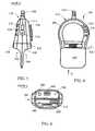
- Apparatus 100comprises an applicator or device 104 adapted for sliding movement on a subject skin, a docking unit 108, and a cord 112 (shown partially) connecting between applicator 104 and docking unit 108.
- Cord 112enables electric and fluid communication between applicator 104 and docking unit 108.
- Apparatus 100may receive power supply from a regular electric supply network receptacle.
- Applicator 104may receive power supply from a rechargeable or regular battery. Docking unit 108 would typically charge the rechargeable batteries of applicator 104.
- FIG. 2is a schematic illustration of an exemplary embodiment of the docking unit of the apparatus for personal use for skin treatment.
- Docking unit 108includes a number of push buttons 200 located on panel 204 and enabling the user to operate apparatus 100 ( FIG. 1 ), a number of operational status indicators 208 informing the operator on the status of different procedures performed with the help of the apparatus 100, and a docking bay 212 receiving applicator 104.
- a receptacle(not shown) facilitates connection of the docking unit to a regular electric supply network.
- Push buttons 200may have built-in LEDs or other light sources and serve as additional process status indicators.
- FIG. 3is a schematic illustration of an exploded assembly of the docking unit of the apparatus for personal use for skin treatment.
- Docking unit 108houses a control board 300, a power supply 304, where the power supply may include a transformer with or without current rectifier, a cooling fan 308, vacuum pump 312, and other auxiliary units that may provide additional functionality beneficial to the selected skin treatment.
- Control board 300controls almost all functions of the apparatus 100 ( FIG. 1 ) and communicates with a control board 708 ( FIG. 7 ) of applicator 104.
- Power supply 304provides the necessary for operation of different skin treatment modules electric power.
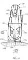
- FIG. 4is a schematic illustration of a frontal view of an exemplary embodiment of the applicator of the apparatus for personal use for skin treatment.
- Applicator 104is shown to include an ergonomically designed casing 404 which fits the hand palm, having a first or distal end at which infrastructure frame 408 is located and a second end 412.
- the second end 412includes a receptacle 416 enabling connection of applicator 104 with help of cord 112 ( FIG. 1 ) to docking unit 108.
- a grip sensor 420located on both sides ( FIGS. 4 and 5 ) of applicator 104, an ON/OFF indicator 424 informing the user of the operational status of the illumination module 1500 ( FIG.
- the applicator and indicator 428informing the user on type of the skin (fair or dark) treatment module inserted in the applicator 104 and their operational status. It may also inform him of the type of treatment for which the cartridge is indicated (For example hair removal, skin rejuvenation, acne treatment, and etc.). It should be emphasized that the concept can also work with no indication at all from the module as to the type of treatment.
- the modulewill operate according to the type of treatment of for which the cartridge was dedicated and the settings made on the base (high, medium, or low power) will change automatically according to the cartridge inserted in a way completely transparent to the user.
- the apparatuswill detect automatically the type of the cartridge.).
- the indicators depending on their statemay light with the same or different color and a combination of indicators and their colors may indicate presence and operation of a particular skin treatment module.
- Grip sensor 420serves as a safety feature. When a user holds applicator 104 he or she naturally presses grip sensor 420 and enables different voltage supplies to different functional modules inserted into infrastructure frame 408.
- the first end of applicator 104features two receiving bays shown in FIGS. 5 and 6 accepting different cosmetic skin treatment modules.
- FIG. 5is a schematic illustration of a side view in the direction of arrow E of an exemplary embodiment of the applicator of the apparatus for personal use for skin treatment.
- the distal or first end 408 of applicator 104includes two receiving bays 504 and 508 operative to receive at least one of a group of modules for performing cosmetic skin treatment.
- modules for performing cosmetic skin treatmentmay be a module for hair shaving, a module for hair depilation or epilator module, a module for skin illumination, a skin abrading module, a skin massaging module, and other modules.
- electric contacts of each of the modulesmay be configured to activate electricity supply to the module only when the module is inserted into the appropriate location.
- Push button 512is an ON/OFF switch that activates or switches off one of the modules for skin illumination 1500 ( FIG. 15 ) when such is inserted in the appropriate receiving bay.
- Push button 516activates other modules. In addition to this a number of pushes on the button 516 may enable setting different operating parameters for each of the modules.
- a decorative cover 520covers an air intake opening of the applicator 104.
- FIG. 6is a schematic illustration of a bottom view in the direction of arrow G of the exemplary embodiment of the applicator of the apparatus for personal use for skin treatment.
- Receiving bay 508is operative to receive and provide a mechanical and electrical interface to any one of the skin treatment modules having an identical interface. Such modules may be a module for hair shaving, a module for hair depilation, acne RF and vacuum treatment module, a module for skin rejuvenation, a skin massage module, and other.
- Connector 604has a type of key mechanism preventing insertion of a non-matching type of module and opening 606 serves for connection to vacuum pump 312 ( FIG. 3 ).
- Receiving bay 504is operative to receive and provide a mechanical and electrical interface to any one of the illumination modules.
- Such modulesmay be a module that includes an incandescent lamp, a module with xenon lamp or Xenon IPL lamp, a module with laser diode, LED, or a combination of two or more of illumination sources or other modules with matching interface.
- Connector 608also has a type of key mechanism preventing insertion of a non-matching type of module.
- each of the skin treatment modulesincludes a tag identifying the module and setting the module operational parameters.
- the tagmay be an RFID, EEPROM, or a simple electronic circuit with unique characteristics such as resistance, capacitance, and others.
- Opening 612provides an input channel to a flow of cooling fluid, which may be a gas or simply air.
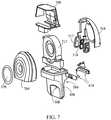
- FIG. 7is a schematic illustration of an exploded assembly of the applicator of the apparatus for personal use for skin treatment.
- Applicator 104includes a two part case 704 incorporating a control printed circuit board 708 which for packaging purposes is divided into a number of electrically communicating segments, a blower or a fan 712 providing a stream of cooling fluid to the illumination module (not shown), and grip sensors 420.
- the blower 712is rotary blower that blows air shown by arrows 1828 ( FIG. 18 ) into one side of the illumination or optical radiation providing module, cools the disposable cartridge 1800, the source of optical radiation 1808 and the reflector 1812 and emerges from the opposite side as shown by arrows 1828 of the optical radiation providing module.
- Control circuit board 708may include different sensors such as movement direction sensors, accelerometers, impedance sensors, and others as well as control circuitry of micro switches operated by insertion of different module, temperature sensors processing circuits, module tag identification and treatment parameters setting circuit, and others.
- some of the sensorsmay be located in appropriate skin treatment modules and their processing circuits may be located on control board 308 ( FIG. 3 )
- At least one optional audio status indicatorsuch as a buzzer signaling to the user the status of skin treatment process parameters may be attached to applicator I04.
- a buzzermay be located in base unit I08.
- FIG. 8is a schematic illustration of a perspective view of an exemplary embodiment of a shaver module of the apparatus for personal skin treatment.
- Shaver module 800includes a case 804 incorporating a hair shaving or hair removal mechanism 808 to be disclosed in detail below, a pair of release buttons 812 enabling easy shaver module release from the applicator, a keyed connector 816, and a tag identifying the module and setting the module operational parameters.
- the tagmay be an RFID, EEPROM, or a simple electronic circuit with unique characteristics such as resistance, capacitance, and others.
- FIGS. 9 through 12are schematic illustrations of the hair removal or shaving mechanism of the present apparatus for skin treatment and different states explaining the mechanism operation.
- FIG. 9illustrates a first state of the operation of an exemplary hair removal mechanism in operation.
- FIG. 10illustrates a second state of operation of the exemplary hair removal mechanism in operation.
- hair removal mechanism 900may include at least one, and in some embodiments more than one, set of tweezers 908 attached to a holder 316 rotating around axis 912. Adjacent to tweezers 908 attached to the same axes is an optional lever 920 terminated by a blade 924.
- lever 920may be rigidly coupled to tweezers 908 to ensure a constant follow-up after tweezers 908.
- tweezers 908There is a preset difference or offset between the location of tweezers 908 and the location of blades 924 of lever 920 with respect to skin 930.
- blade 924would be located closer to skin 930 than tweezers 908.
- the difference in the location of blade 924 and tweezers 908may be regulated according to the type of skin, hair, and particular treated segment of the subject casing.
- tweezers 908are applied to skin 930.
- Holder 916rotates in the direction indicated by arrow 928 and concurrently with rotation may move linearly on the surface of skin 930 in the direction indicated by arrow 932.
- tweezers 908continue to rotate to the second state, they pick-up at least one hair shaft or follicle 904 ( FIG. 10 ) and begin pulling it out of skin 930.
- a pulling force generated by the rotation of tweezers 908 and assisted by linear movement of holder 916 applied to hair shaft 904pulls together with hair shaft 904, skin 930 surrounding the hair shaft and follicle.
- This forcedeforms skin 930 and forms a type of goose bump or goose pimple 1040 protruding over the rest of the skin surface surrounding the follicle.
- Blade 924cuts hair 904 ( FIG. 11 ) substantially close to the peak of goose bump 1040.
- the pulling forceis set to a particular tension with respect to the hair that is sufficient to tension the hair shaft but not to pull it out of the skin.
- FIG. 13is a magnified schematic illustration of a cut and retracted back hair shaft or follicle. Following the cut of hair shaft 904, skin 930 that formed goose bump 1040, retracts or returns to its normal at rest state.
- the residuals 906 of hair shaft 904retract to the original position.
- the residual 906 of hair shaft 904retracts deeper than skin surface or stratum corneum 930, such depth being indicated by numeral 1304, which marks the difference in the locations of the cut end of the residual 306 of the hair shaft 904 and skin surface 930.
- numeral 1308indicates the underlying tissue.
- FIG. 11illustrates a third state of the operation of the exemplary hair removal mechanism in operation.
- FIG. 12illustrates a fourth state of operation of the exemplary hair removal mechanism.
- Holder 916FIGS. 11 and 12
- tweezers 908catch another hair shaft 904 and form bump 1040 in the fourth operational state in a way similar to the one explained above.
- hair 904is cut in a way similar to the way that the previous hair shaft was cut.
- the tweezers 908 and blades 924may be orientated in the same direction or staggered and oriented in different directions.
- tweezers 908 and blades 924When some of the tweezers 908 and blades 924 are oriented in different directions, the user may move back along the earlier treated skin segment and still be efficacious. When tweezers 908 and blades 924 are orientated in the same direction the user at the end of treatment stroke may rotate applicator 104 ( FIGs. 1 and 4 ) and move it in the opposite direction or simply reposition it to treat the next skin segment.
- the hair removal mechanism 808may be any one of the well-known mechanical hair removal mechanisms such as a razor, shaving, or an electric shaver such as for example, feminine electric shaver commercially available from Braun GmbH, Germany - model 3470 Softperfect.
- This modelalso includes other detachable heads of plucking and tweezing mechanisms. Similar or even the same mechanisms are also, of course, applicable to male hair removal/shavers.
- the illumination head/smay be attached and operate with a conventional shaver or epilator with only one head of either a shaver or epilator, or even a razor.
- the hair removal mechanismmay be an interchangeable mechanism, where the mechanism most appropriate for the task is assembled on the applicator.
- FIG 14is a schematic illustration of another exemplary embodiment of the hair removal mechanism.
- a comb type protective plate 1400protects skin 930 and especially bumps 1040 from occasional damage by rotating blades 924 ( FIG 3 ).
- the comb type protecting plate 1400may be attached to the applicator 104 or held independently by a user.
- Blades 924may be replaced by a fixed blade, which would cut hair 904 pulled by tweezers 908.
- holder 916 in addition to rotationmay have a linear motion.
- two comb-like blades linearly sliding with respect to each othermay be implemented to cut the hair.
- FIG. 15is a schematic illustration of a three-dimensional view of an exemplary embodiment of a skin illumination module of the apparatus for personal skin treatment.
- Module 1500includes a case 1504 incorporating one or more illumination sources, a pair of release buttons 1512 enabling easy illumination module release from the applicator, and a keyed connector 1516.
- a transparent protective window 1520protects the illumination source.
- a pair of RF electrodes 1524 located along the protective windoware operative to provide RF energy or radiation to the treated skin segment (not shown).
- the illumination sourcesemit large amount of heat.
- the heatas it will be explained in detail below is evacuated from the module by a cooling fluid flow or air generated by blower 712 ( FIG. 7 ) through exhaust opening 1528.
- module 1500As explained above insertion of skin illumination or optical radiation providing module 1500 ( FIG. 15 ), into its location in applicator 104 activates a module type detection mechanism. This prevents idle or erroneous operation of module 1500 and other skin treatment modules that the user may use. For example no high voltages will be present and "alive" in the RF electrodes 1524 of the module 1500 so that no one is subject to high voltage danger if the disposable cartridge is removed. As an additional safety measure, supply of RF energy to electrodes 1524 may be enabled only when both electrodes are applied to skin and the impedance between the electrodes is above certain threshold value.
- Module 1500may be configured to operate as an illumination module only, as an RF energy applying module or both of them. In some embodiments a temperature sensor such as for example, a thermocouple may be mounted into one or both electrodes.
- FIG. 16is a schematic illustration of a rear view of the skin illumination module of FIG. 15 .
- the FIG.shows cooling fluid intake opening 1604 through which the stream of cooling fluid, which may be air, enters module 1500 and is exhausted through exhaust opening 1528 ( FIG. 15 ) and a rear side1608 of a disposable cartridge containing one or more illumination or light sources.
- Illumination module 1500may include a variety of sources, a few non-limiting examples include an incandescent lamp, xenon lamp, laser diodes, LED, laser diodes or even a combination of two or more of these sources as well as other sources.
- the illumination sourcesmay operate in a pulsed, continuous, graduated, modulated, oscillating or other operation mode as well as a combination of two or more of these modes. The power and operational times of the sources are selected to avoid potential damage to the treated segment of skin.
- each of the illumination sourcesmay be packed in a cartridge-like packaging detachable from the illumination module 1500.
- the cartridge like packaging of the illumination sourceadvantageously allows different illumination sources to be used with the same illumination module and applicator.
- the cartridgefurther includes a tag identifying the module and setting the module operational parameters.
- the tagmay include a permanent data record which stores the type of the module, type of recommended treatment and recommended treatment parameters and a variable data record.
- the operational parametersmay include optical and or RF power setting for fair or dark skin and for the various treatments which are each uniquely associated with the cartridge (e.g. cartridge type #1 for hair from fair skin removal, cartridge type #2 for hair from dark skin removal, cartridge type #3 for skin rejuvenation, cartridge type #4 for acne treatment, as well as other types of cartridges.) pulse duration and others.
- the variable data recordenables recording the amount of events in course of which the module was operative.
- the data recorded into the tagenables upon the tag insertion into the applicator operation of the module.
- the tagmay be an RFID, EEPROM, or a simple electronic circuit with unique characteristics such as resistance, capacitance, and others.
- the modulesmay be color coded facilitating easy distinction between them and avoiding erroneous use of the module.
- FIG. 17is a schematic illustration of a side planner view in the direction of arrow L of the illumination module of FIG. 15 and FIG. 18 is a cross section along plane D-D of the illumination module of FIG. 17 illustrating details of an exemplary embodiment of an illumination cartridge of the apparatus for personal skin treatment.
- Disposable cartridge 1800includes a source of optical radiation 1808, a reflector 1812 configured to reflect the emitted optical radiation to the segment of the skin (not shown) to be treated, and a dielectric coated protective window 1816.
- Window 1816defines the aperture through which the optical radiation is emitted to the skin.
- the source of optical radiation 1812may be an incandescent lamp such as AGAC 4627 high power density Xenon flash lamp commercially available from Perkin Elmer Optoelectronics Wenzel-Jaksch Str. 31 65199 Wiesbaden, Germany or any one of a group of LED, laser diode, solid state laser, a gas laser, or a Xenon IPL (Intense Pulsed Light) lamp.
- Reflector 1812is a prismatic case or a rectangular body with flat facets and polygonal cross section or a tubular cross section with an optional curvature of second or higher power. It may be a simple round cylinder cross section, a parabolic cross section or any other cross section allowing the optical radiation to be emitted across the aperture of window 1816 through which the optical radiation is emitted to the skin.
- the dielectric coating of window 1816is selected such as to transmit the relevant sections of optical radiation spectrum to the treated segment of the skin and reflect the other.
- Reflector 1812has butt end openings 1820 allowing air passage inside the reflector.
- the dielectric coated protective window 1816 located adjacent or attached to the open longitudinal section of reflector 1812forms with the reflector 1812 an air-conducting channel 1824 bound on one side by reflector 1812 and on the other side by window 1816.
- a part of the stream of cooling air shown by arrow 1828 generated by a cooling fan 712enters channel 1824 through butt end opening 1820 of reflector 1812. It is directed into the air-conducting channel 1824 along the source of optical radiation 1812 and cools it.
- Butt end openings 1820 of reflector 1812terminate air-conducting channel on both of it ends and serve as cooling air exhaust openings.
- the area of reflector 1812 air exhaust openings 1528is at least equal or larger to the area of openings 1820 allowing air passage into inner part of reflector 1812 and air conducting channel 1824.
- a part of cooling air stream 1828may be directed to flow around the external section of reflector 1812 and cools the outer section of reflector 1812.
- rotary blower 712( FIG. 7 ) blows cooling air shown by arrows 1828 into one side of the disposable cartridge 1800 where the air flows in parallel (along) to the source of optical radiation 1808 and the reflector 1812 and emerges from the opposite side as shown by arrows 1828 of the optical radiation providing module 1800.
- a second glass window 1520is installed in parallel to window 1816 and part of the cooling air blown by the blower 712 and marked by arrow 1828 flows between the two windows 1520 and 1816.
- a slanted lamp electrode 1844as shown in FIG. 18 , may be installed on the air intake side of the optical radiation source 400, to enhance air flow in the direction of the windows.
- Arrows 1828schematically illustrate the cooling air flow inside and outside reflector 1812 and between the windows 1520 and 1812.
- a bended support 1852 of reflector 1812prevents return flow of hot air.
- Windows 1520 and 1838may be made of Pyrex®, sapphire, quartz, or specially treated borosilicate glass.
- Window 1030 or both windowsmay be coated with a dielectric coating serving as a filter for reflecting back undesired wave lengths, such as UV and certain IR wavelengths, emitted from the optical radiation source 1808.
- a thermal sensorsuch as a thermistor or any other type of temperature measuring sensor may be installed on either inflow or the outflow end of the cooling air, as a safeguard against overheating in case of malfunction of the cooling means.
- temperature sensorsmay be installed in any other designated point in the cartridge and be operatively configured to sense the temperature in such designated point in the cartridge and communicate the temperature to the controller board 708 ( FIG. 7 ).
- two reflectorsmay be mounted between the two windows (1520 and 1816), on both sides thereof, to prevent light scattering outside the treatment area.
- the disposable cartridge 1800 of applicator 104may be made of a plastic material containing an amount of titanium dioxide (TiO 2 ) sufficient to disperse the reflected illumination.
- Module 1500may operate in pulsed or continuous operation mode. It is known that low repetition rate optical radiation or light pulses are annoying the user who may be constantly visually tracking the applicator location. In order to ease the user's sensation, the optical radiation source may emit a number of low power light pulses interleaved between high power treatment pulses, increasing the repetition rate of the light pulses to a frequency of 16 Hz or more and alleviating the annoying and eye disturbing effects of low repetition rate light pulses.
- an RFID deviceis connected to cartridge 1800 communicating with control circuit 708 ( FIG. 7 ).
- the RFID deviceis preloaded with a maximal number of pulses to be emitted before the cartridge 1700 of illumination providing module 1500 has to be replaced and decreases the count with every emitted pulse.
- the RFID deviceis preloaded with a total energy that may be applied to the skin in a single treatment before the cartridge 1800 of the illumination providing module 1500 ( FIG. 15 ) has to be replaced.
- the RFID devicemay also serve as an additional safety measure, where the control circuit 708 prevents the radiation providing module 1500 from emitting pulses if the RFID is not identified, namely the optical radiation or illumination providing module 1500 has not been installed correctly.
- a 1024 Bit 1-Wire EEPROMsuch as DS2431 commercially available from Maxim/Dallas Semiconductors, Inc., Sunnyvale, CA 94086 U.S.A.
- 1-Wire EEPROM operating as a countercan be assembled on the control printed circuit 708 that among others controls the radiation providing module 1500. Similar to the RFID the counter may be pre-loaded with the desired information. The same 1-Wire EEPROM may function for radiation providing module 1500 authenticity identification.
- FIG. 19is a schematic illustration of a cross section of an exemplary embodiment of the applicator with illumination module of the apparatus for personal skin treatment.
- illumination module 1500 containing one or more illumination sourcesis inserted into a receiving bay 504 of the applicator 104.
- Keyed connector 1516ensures that only compatible modules could be inserted into receiving bay 504 of applicator 104.
- FIG. 20is a schematic perspective illustration of an exemplary embodiment of the epilator module of the apparatus for personal skin treatment.
- Epilator module 2000includes a case 2004 incorporating a hair epilating or hair removal mechanism 2008 to be disclosed in detail below, a pair of release buttons 2012 enabling easy epilator module release from the applicator, a keyed connector 2016, and a tag identifying the module and setting the module operational parameters.
- the tagmay be an RFID, EEPROM, or a simple electronic circuit with unique characteristics such as resistance, capacitance, and others.
- the epilator mechanismmay be such as Silk-epil, commercially available from Braun GmbH, Germany.
- FIG. 21is a schematic illustration of a frontal view of an exemplary embodiment of a skin rejuvenation module of the apparatus for personal skin treatment.
- Skin rejuvenation module 2100includes a case 2104 incorporating a matrix of skin rejuvenating electrodes 2108, a pair of release buttons 2112 enabling easy epilator module release from the applicator, a keyed connector 2116, and a tag identifying the module and setting the module operational parameters.
- the tagmay be an RFID, EEPROM, or a simple electronic circuit with unique characteristics such as resistance, capacitance, and others..
- skin abrasion module 2300may also be used for skin rejuvenation.
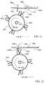
- FIG. 22is a schematic illustration of an exemplary embodiment of the skin rejuvenation electrodes of the skin rejuvenation module of the apparatus for personal skin treatment.
- the skin rejuvenation electrode 2108 disclosed in detail in US Patent Application Serial Number 12/505,576 to the same assignee filed on July 20 , 2009,is a segmented electrode and it includes a central segment 2204 being in size of about 15 to 20mm wide and two peripheral segments 2208 arranged along the circumference/perimeter of segment 2204.
- Central segment 2204is populated by a plurality of small terminated by a spherical shape or flat RF providing electrodes 2212.
- Thermal and electrical insulation 2216 between central segment 2204 and peripheral segments 2208is also illustrated. Typically, the thermal and electrical insulation is about 0.5-1.0mm wide.
- the peripheral segments 2208about 2 to 4mm wide and are made of a thermally conductive material.
- Electrodes 2212are made of electrically conductive material and electrodes 2208 are made of electrically conducting or ceramic material.
- the tested segments 2208 of the electrodeswere made of materials selected from a group consisting of metal oxides or Ceramics. Aluminum nitride, Boron nitride, and similar are examples of such materials.
- Electrode 2108may be of rectangular, elliptical or other suitable shape or even a flat surface. Electrodes 2208 may have uniform width or sections of different width. In some embodiments the electrodes may be coated by a dielectric coating.
- RF sourcemay provide RF energy to the electrodes and a thermal sensor may be incorporated in each of the electrodes.
- FIG. 23is a schematic illustration of a frontal view of an exemplary embodiment of a skin abrading module of the apparatus for personal skin treatment.
- Skin abrading module 2300includes a case 2304 incorporating a skin abrading roll 2308, a pair of release buttons 2312 enabling easy abrading module release from the applicator, a keyed connector 2316, and a tag identifying the module and setting the module operational parameters.
- Skin abrading roll 2308may be a metal or plastic roll coated with fine diamond powder or by fine ScotchBrightTM type material.
- abrading roll 2308may be a soft material roll coated by fine ScotchBrightTM type material or completely made of a ScotchBrightTM type material.
- a DC motor and a gear mounted in the inner compartment of case 2304provide rotation to skin abrading roll 2308.
- skin abrading roll 2308may rotate such that linear speed of surface 2320 of skin abrading roll 2308 would be greater or smaller than the speed with which user displaces the skin abrading module 2300.
- skin abrading roll 2308may rotate in a direction where the linear speed of surface 2320 matches the skin abrading module 2300 displacement direction.
- skin abrading roll 2308may rotate in a direction where the linear speed of surface 2320 is oriented in a direction opposite to the skin abrading module 2300 displacement direction.
- skin abrading roll 2308may be replaced by two or more diamond coated or ScotchBrightTM coated rolls rotating with different speed and pulling in between then different segments of treated skin. Abraded, dead, or flat stratum corneum skin cells may be removed later by a soft pad and a skin cooling lotion or cream.
- skin abrading module 2300may have a vacuum slit or vacuum openings implemented in the skin abrading roll that would remove by suction abraded stratum corneum particles.
- Displacement speed monitoring arrangementmounted on controller board 708 ( FIG. 7 ) could be in communication with the controller controlling module 2300 movement and set a proper displacement speed, leaving to the user discretion application of proper for particular treatment pressure.
- FIG. 24is a schematic illustration of a frontal view of an exemplary embodiment of a skin massaging module of the apparatus for personal skin treatment.
- Skin massaging module 2400includes a case 2404 incorporating a skin massaging roll 2408, a pair of release buttons 2412 enabling easy massaging module release from the applicator, a keyed connector 2416, and a tag identifying the module and setting the module operational parameters.
- Skin massaging roll 2408may be a metal or plastic roll in which a series of grooves 2420 and protrusions or ribs 2424 is made.
- roll 2408may have a type of braking mechanism resisting displacement of skin massaging module 2400 across the treated skin segment. In course of module 2400 displacement, skin enters grooves 2420 and is massaged by protrusions 2424.
- a DC motor and a gear mounted in the inner compartment of case 2404may provide rotation to skin massaging roll 2408.
- the rotation speed of roll 2408may be selected such as to enable pull of the skin into grooves 2420.
- FIG. 25is a schematic illustration of another exemplary embodiment of the skin massaging roll of the skin massaging module of the apparatus for personal skin treatment.
- Skin massaging roll 2408may be a single roll or an assembly of two or more rolls 2504 and 2408.
- Rolls 2504 and 2508may have identical protrusions 2420 and grooves 2424.
- rolls 2504 and 2512may have protrusions directed in opposite direction. Each of the rolls may rotate at a different speed enhancing the skin massaging action.
- FIG. 26is a schematic illustration of an additional exemplary embodiment of the skin massaging roll of the skin massaging module of the apparatus for personal skin treatment.
- Roll 2108includes a plurality of vacuum openings 2616 operative to suck the skin into grooves 2624 between protrusions 2420 further enhancing the massaging action of the skin massaging module 2400.
- the massaging modulemay be implemented to support a difference in the linear speed of the massaging roll 2408 and the speed applicator 104 displacement over the skin. This may further enhance the massaging action.
- One of the interchangeable modulesmay be an ultrasound providing module.
- Provisional Patent application serial number 61/248,997 filed on October 6, 2009 to the same assigneediscloses such a module and a method of ultrasound to skin application, where the transducers are positioned at a predetermined distance from each other on opposing borders of an area of skin being treated and at a predetermined angle relative to the surface of the skin.
- the angle between the transducersis maintained by a wedge made of a sound index - matching material as known in the art.
- the distance between the transmitter and receiveris dependent on the thickness of the tissue at the area to be treated.
- the transducersare operative to emit ultrasound beams, commonly in pulse form, at an angle relative to the surface of skin to be treated so that a portion of the emitted beams impinge upon skin tissue at a Brewster's angle of incidence, and follow propagation path, which is generally parallel to the surface of the skin through treated area producing a desired skin treatment effect.
- FIG. 27is a schematic perspective illustration (of a frontal view) of an exemplary embodiment of a vacuum module of the apparatus for personal skin treatment.
- Module 2700includes a case 2704 incorporating a miniature vacuum pump 2708, a pair of release buttons 2712 enabling easy vacuum module release from the applicator, a keyed connector 2716 through which power is supplied to the miniature vacuum pump and identifying and proper locating the module, and a tag 2720 identifying the module and setting the module operational parameters.
- the tagmay be an RFID, EEPROM, or a simple electronic circuit with unique characteristics such as resistance, capacitance, and others.
- Suction opening 2724is surrounded by a suction cup 2728 attaching the module to the skin surface.
- Cup 2724may be made of a soft antiallergenic material such as polyurethane, silicone, or similar.
- Vacuum suctionremoves from the skin for example, abraded epidermis particles, acne, black and white heads, and other debris.
- the exhausted airis evacuated from the module through an exhaust tube 2732 communicating with vacuum pump 312 ( FIG. 30 ) through opening 606 ( FIG. 6 ).
- the sucked in debrisis retained inside module 2700 and disposed upon completion of the treatment.
- the debrismay be collected in the docking unit 108 ( FIG. 1 and 3 ) and disposed periodically.
- the debrismay be evacuated through exhaust tube 2732 with the rest of the air, in the simplest form.
- Module 2700 across the skin displacementallows gentle massaging of the treated skin area and thus loosens/softens the acne blackheads or the whiteheads from the root
- the module 2700can be a disposable module
- FIG. 28is a schematic perspective illustration of another exemplary embodiment of a vacuum module of the apparatus for personal skin treatment.
- Module 2800includes a case 2804, a pair of release buttons 2812 enabling easy module release from the applicator, and a keyed connector 2816.
- connector 2816is a dummy connector. It does not convey electric signals and serves mainly as means to stabilize the module in place.
- connector 2816may carry electrical signals from the tag.
- a connecting tube 2820enables vacuum module 2800 through opening 606 ( FIG. 6 ) connection to vacuum pump 312 ( FIG. 3 ).
- Suction opening 2824is surrounded by a suction cup 2828 attaching the module to the skin surface.
- Cup 2824may be made of a soft antiallergenic material such as polyurethane, silicone, or similar.
- Vacuum suctionremoves from the skin for example, abraded epidermis particles, acne, black pimples and others. Collected debris may be retained inside module 2800 and the sucked-in air may be evacuated from the module through a regular exhaust opening in docking station 108 ( FIG. 1 and 3 ). Alternatively, the debris may also be evacuated through a regular exhaust opening in the docking station.
- Module 2800may be implemented as a disposable module.
- FIG. 29is a schematic perspective illustration of an exemplary embodiment of a combined RF and vacuum module of the apparatus for personal skin treatment.
- Module 2900includes a case 2904 incorporating a pair of RF electrodes 2908 operative to couple RF energy to the treated segment of skin, a pair of release buttons 2912 enabling easy module 2900 release from the applicator, a keyed connector 2916, and a tag 2920 identifying the module and setting the module operational parameters.
- the tagmay be an RFID, EEPROM, or a simple electronic circuit with unique characteristics such as resistance, capacitance, and others.
- Suction opening 2932is surrounded by a suction cup 2928 attaching the module to the skin surface.
- Cup 2928may be made of a soft antiallergenic material such as polyurethane, silicone, or similar.
- a connecting pipe or tube 2924enables vacuum module through opening 606 ( FIG. 6 ) to vacuum pump 312 ( FIG. 3 ) connection.
- Vacuum suctionmay remove from the skin abraded epidermis particles, acne, black and white heads, and others.
- the level of vacuumis selected to cause the desired effect and still enable continuous displacement of the applicator over the skin surface. This module displacement allows gentle massaging of the treated skin area assisting in acne removal and other procedures.
- FIG. 30is a schematic illustration of an exemplary embodiment of a combined illumination, RF, and vacuum providing module of the apparatus for personal skin treatment.
- Module 3000may be implemented as a combination of the illumination cartridge 1500 and vacuum module 2700 or 2800.
- Module 3000includes a case 3004 incorporating an illumination module 3008 with the illumination cartridge operative to couple illumination to the treated segment of the skin and vacuum module 3010.
- Cartridge 3008is generally similar to cartridge 1500, although the dimensions and configuration may be different.
- Cartridge 3008includes a pair of RF electrodes 3024 similar to electrodes 1524 ( FIG. 15 ) of cartridge 1500 operative to couple RF energy to the treated skin segment, a pair of release buttons 3012 enabling easy module 3000 release from the applicator, and a keyed connector 3016.
- Cartridge 3008may be surrounded by a suction cup 3028 with vacuum openings 3032 communicating through module 3010 and vacuum connecting tube or pipe 3020 through opening 606 ( FIG. 6 ) to vacuum pump 312 ( FIG. 3 ).
- vacuumis supplied to suction cup 3028 it operates to attach module 3000, or more specifically, attach module 3008 to the skin surface.
- Cup 3028may be made of a soft antiallergenic material such as polyurethane, silicone, or similar.
- Vacuum suctionremoves for example, abraded epidermis particles, acne, black and white heads, and others. The vacuum is beneficial not only in removing the debris. It's also beneficial in the coupling of optical and RF energy to the tissue.
- Module 3000 displacementallows gentle massaging of the treated skin area assisting in acne removal. Vacuum also stretches the skin being in contact with the protective glass of illumination module 3008. This increases the efficiency of the illumination by reducing illumination scattering present when a gap between the protective glass and the skin exists as well as scattering by the dermal structure of the skin.
- Module 3000is a combination of a disposable illumination cartridge and a disposable vacuum cartridge and as such may be implemented as a disposable module. Additionally, cup 3028 may be implemented as a disposable cup.
- Module 3000may include a tag 3040 identifying the module and setting the module operational parameters. The tag may be an RFID, EEPROM, or a simple electronic circuit with unique characteristics such as resistance, capacitance, and others.
- FIG. 31is a schematic illustration of an exemplary configuration of the applicator with an illumination module and an epilator module of the apparatus 100 ( FIG 1 ) for personal cosmetic skin treatment.
- modules 1500 and 2000are slid as shown by arrow 3100 into their respective receiving bays 504 and 508 and positively fixed in their locations.
- Electronics located on printed circuit board 708FIG. 7 ) recognizes the identification tag of the module and sets its operating parameters.
- Applicator 104is now ready for use and set to perform at least two procedures, as will be explained below, enabled by the inserted modules.
- the user presses release buttons 1512 or 2012extracts the earlier inserted module and inserts a different desired module.
- the usermay assemble any other combination of different modules and perform different cosmetic skin treatment.
- FIG. 32is a schematic illustration of an exemplary method of cosmetic skin treatment using the present applicator/ device and apparatus.
- applicator 104is applied to a segment of skin 3200 to be treated, enabling firm or at least mostly firm contact between the RF electrodes 1524 ( FIG. 15 ) and the skin.
- Optical radiation providing module 1500is activated and it illuminates the skin section to be treated and the RF energy supplied to the electrodes 1524 weakens hair roots and hair follicle or even destroys them.
- the user or a built-in mechanism for continuously displacing the device across the skindisplaces device 104 in a desired direction indicated by arrow 2404, for example, along the segment of the skin to be treated.
- optical radiationis directed through aperture of illumination cartridge 1500 to irradiate a segment of skin 3200 to be treated by a constant optical radiation power and RF energy, both set by the appropriate module identification tag and supplied in continuous or pulsed mode, and the applicator 104 is displaced along the skin segment to be treated in the direction of arrow 3204.
- Displacement speed monitoring arrangement mounted on controller board 708may set a proper displacement speed.
- the displacement speed - optical radiation power or RF energy dependencemay be prepared and loaded as a look-up-table (LUT) into control circuit 708 or 300.
- LUTlook-up-table
- the usermanually repositions device 104 on the next segment of skin to be treated or on another non-treated segment of the skin and sets it for displacement into the same or opposite direction.
- the danger of causing skin burns by treating the same segment of skin twiceis reduced, since there is some time for the skin to cool down between successive skin treatments by device 104.
- Optical radiation coupled with the RF energyretards future hair growth on the treated segment of the skin by heating hair follicle.
- RF energy applied to the same skin segmentalso heats deeper skin layers where hair bulbs and follicles are located, enhancing the hair removal process performed by the optical radiation. Weakened hair may be easier removed by an epilator module 2000 that follows the illumination module.
- Some skin pretreatment operationssuch as skin cleaning performed by water and soap or other cleaning means, may be introduced.
- the frequency of the RF energy applied for the skin treatmentis typically in the range of 6.0 MHz to 7.0 MHz and generally does not require application of gel improving electric contact between electrodes 1524 and skin 3200.
- the userapplies the applicator or skin treatment device 104 to a skin segment from which hair has to be removed.
- the epilatoris moved in the direction indicated by arrow 3232 and the hair is removed from the skin segment by mechanical means, for example by epilator module 2100.
- optical radiationof proper power and wavelength is applied to the same segment of skin that was treated.
- RF energymay be applied to the same segment of skin.
- Application of optical radiation and RF energyretards further hair growth. Similar to the earlier disclosed method the user displaces the applicator 104 or the applicator displacement mechanism displaces itself automatically from a treated skin segment to another untreated skin segment.
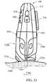
- FIG. 33is a schematic illustration of another exemplary method of skin treatment using the present applicator and apparatus.
- applicator or device 104is applied to a segment of skin 3300 to be treated, enabling firm or at least mostly firm contact between the RF electrodes 1524 and the skin 3300.
- the user, or a built-in mechanism for continuously displacing the device across the skindisplaces device 104 in a desired direction indicated by arrow 3304, for example, along the segment of the skin to be treated.
- RF energyis applied to electrodes 2208 and 2212 ( FIG. 22 ) of the skin rejuvenation module 2100.
- stratum corneumthe upper skin layer
- stratum corneumresists electrical breakdown.
- an electrical dischargetakes place.
- the absence of a conductive fluid between the skin 2504 and the electrodes 2208 and 2212 of the applicator 104allows the device to achieve a higher skin break-down potential and prevents the occurrence of a short circuit between the individual voltage supplying elements 2212.
- the absence of a conductive fluidalso facilitates limiting fractal skin damage caused by the RF voltage or energy radiating from the dome type contacts 2212 to the skin contact points only.
- the dischargeablates the stratum corneum and since the coupling between voltage supplying elements terminated by domes 2212 and the skin 2500 is a conductive coupling, it enables electric current flow from the apex of dome 2212 to highly conductive epidermis and dermis and deeper located skin layers. Enabled by skin breakdown, electric current heats and coagulates some of the target section of skin 2800 volume initially in contact with the domes 2212 and in immediate vicinity of domes 2212 generating an array or matrix of microscopic skin wounds.
- the dome shaped form of the voltage applying elements 2212facilitates electric discharge that takes place between the apex of the dome shaped elements 2212 and contact spot on the skin 3200.
- the domes 120however, do not penetrate the skin. Healing of these wounds rejuvenates (tightens) the damaged skin segment and reduces or removes wrinkles existing at this skin segment.
- the illumination module 1500may be equipped by a source of illumination with a wavelength stimulating faster wound healing, such as for example, 450nm or 550nm.
- the optical radiation sourcescan be selected to provide visible, infrared (IR), blue, or even ultraviolet optical radiation at different intensity levels.
- IRinfrared
- the optical radiation sourcesmay be operated in a continuous or pulse operation mode and according to fair or dark skin settings. Operation mode setting may be performed automatically by detecting the skin type by a skintype sensor, or set manually set, or preset according to the type of the cartridge.
- the treatmentmay be enhanced by application to the same skin segment of radio frequency energy.
- the RF energymay be selected to heat the skin and tissue to an effective treatment temperature without ablating the skin.
- the combined energies of optical radiation in the appropriate spectrum range with radio frequency (RF)enable highly selective targeting of the sebaceous glands and acne bacteria. Infrared and RF energies reduce sebaceous gland activity while blue light simultaneously destroys active acne.
- FIG 34is a schematic illustration of an additional exemplary method of skin treatment using the present applicator and apparatus.
- Applicator 104includes skin abrasion module 2300 ( FIG 23 ) and illumination module 1500 ( FIG 15 ).
- applicator 104may be used for such cosmetic skin treatment procedures as skin rejuvenation, wrinkle removal, acne treatment, skin pigmentation treatment, and other skin treatments.
- applicator or device 104is applied to a segment of skin 3400 to be treated and displaced by the user or as disclosed above by activating skin abrasion module 2300 and displaces applicator 104 in a desired direction indicated by arrow 3404, for example, along the segment of the skin to be treated.
- Skin abrasion module 2300removes the electrically isolating stratum corneum layer enabling easy access to bare epidermis layer.
- the particles of the exfoliated stratum corneum layermay be removed by vacuum.
- the skin exfoliation processincreases blood and interstitial fluid flow to the treated skin segment and significantly reduces electrical resistance of the skin.
- Skin illumination module 1500immediately follows abrasion module 2300.
- Low bare epidermis resistanceenables firm firm or at least mostly firm contact between the RF electrodes 1524 and the skin 3400.
- Low electrical resistance of the treated skinenables application of relatively low frequency 300 kHz to 700 kHz deep into skin penetrating RF energy.
- the depth of RF energy penetrationallows treating of collagen and adipose tissue containing layers. These frequencies are also effective in cellulite treatment and destruction.
- the treatmentmay be highly localized (corresponding to the distance between electrodes 1524 of illumination module 1500) and targeted for example, to double chin removal, small skin pigmentation spots removal,
- the process of skin exfoliationincreases blood and interstitial fluid flow to the treated skin segment (stimulating circulation) further increasing heat absorption and accelerating appearance of the desired skin effect.
- the skin abrasion treatment followed by RF and luminous energy application to bare epidermis layerremoves dead cells, stimulates blood circulation enhancing heat in tissue conduction and dissipation, and rejuvenates the skin structure by replacing the old dull skin with fresh, younger cells and encouraging the regeneration of collagen and elastin for firmer, healthier looking skin.
- Acnemay be treated by a combination of abrasion module 2300 and illumination module 1500.
- Abrasion moduleremoves a thin superficial skin layer and proper illumination wavelength of 500 - 550 nm may be used to speed-up the skin healing process.
- topical agentssuch as a polyphenolic based antioxidant serum containing polyphenolic flavonoids and polyphenolic diterpenes (e.g.,epigallocatechin, ursolic acid).
- topical agentssuch as a polyphenolic based antioxidant serum containing polyphenolic flavonoids and polyphenolic diterpenes (e.g.,epigallocatechin, ursolic acid).
- a polyphenolic based antioxidant serum containing polyphenolic flavonoids and polyphenolic diterpenese.g.,epigallocatechin, ursolic acid
- FIG. 35is a schematic illustration of a further exemplary method of skin treatment using the present applicator/device and apparatus.
- Applicator 104includes vacuum module 2700 ( FIG 27 ) or 2800 ( FIG. 28 ) and illumination module 1500 ( FIG 15 ).
- applicator 104may be used for such cosmetic skin treatment procedures as acne treatment, waist tightening, skin pigmentation treatment, and other skin treatments.
- the userapplies applicator or device 104 to a segment of skin 3500 to be treated and activates skin illumination module 1500.
- the userdisplaces applicator 104 in a desired direction indicated by arrow 3504 or 3532, for example, along or across the segment of the skin to be treated.
- skin illumination module 1500in pulse or continuous mode heats skin 3500, softens it and enables vacuum, applied by the vacuum module 2700 or 2800 following the illumination module 1500 to effectively pull out of the skin acne, whiteheads, blackheads, and other impurities.
- the same processmay be targeted for example, to small skin pigmentation spots removal, and other treatments.
- the suctionenables better skin to illumination window and electrodes coupling and accordingly better treatment results.
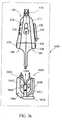
- FIG. 36is a schematic illustration of still another exemplary method of skin treatment using the present applicator/device and apparatus.
- Applicator 104includes a combined illumination and RF module 1500 ( FIG 15 ) and a vacuum module 3000.
- applicator 104may be used for such cosmetic skin treatment procedures as acne treatment, skin pigmentation treatment, hair growth reduction, skin rejuvenation, skin tightening, and other skin treatments.
- applicator or device 3600is applied to a segment of skin to be treated and displaced by the user across the skin segment.
- RF energyis supplied to electrodes and it induces current in the skin. The current heats the skin and softens it.
- RF energymay be supplied in a continuous or pulse mode.
- Illumination modulemay include one or more light sources, for example LEDs, of different wavelength. Certain wavelengths may be applied to accelerate skin surface heating other wavelengths, for example blue or ultraviolet may be applied to disinfect the treated skin segment accelerate skin healing and smoothing or skin rejuvenation.
- the disclosed apparatusenables a casual user in a residential set-up to perform himself or herself almost every skin treatment procedure by using a variety of modules that may be inserted into the infrastructure frame.
- the applicatorsimultaneously receives only two types of skin treatment modules, these may be replaced after use for modules providing a different type of skin treatment.
- Such skin treatment moduleslike epilator, shaver, exfoliation or abrasive module and massage head apply a mechanical action to the skin.
- Ultrasound moduleapplies ultrasound waves to the skin.
- Intense pulsed light and RFapply electromagnetic radiation to the skin.
- a combination of these modulesmay be used to provide a variety of skin treatments such as hair removal, skin rejuvenation, skin exfoliation, acne treatment, circumference reduction, and other skin treatments.
- the effect of some of the treatmentsmay be further enhanced by applying the treatment after a bath or shower when the skin is clean and soft.
- a combination of different modules providing different treatments to the same skin segment for example heat and vacuum, mechanical hair removal and illumination and othershelp to combat almost all types of skin deficiencies regardless treated skin type.
Landscapes
- Health & Medical Sciences (AREA)
- Life Sciences & Earth Sciences (AREA)
- Surgery (AREA)
- Engineering & Computer Science (AREA)
- Veterinary Medicine (AREA)
- Physics & Mathematics (AREA)
- Heart & Thoracic Surgery (AREA)
- Medical Informatics (AREA)
- Molecular Biology (AREA)
- Animal Behavior & Ethology (AREA)
- General Health & Medical Sciences (AREA)
- Public Health (AREA)
- Nuclear Medicine, Radiotherapy & Molecular Imaging (AREA)
- Biomedical Technology (AREA)
- Mechanical Engineering (AREA)
- Forests & Forestry (AREA)
- Otolaryngology (AREA)
- Optics & Photonics (AREA)
- Plasma & Fusion (AREA)
- Electromagnetism (AREA)
- Oral & Maxillofacial Surgery (AREA)
- Pathology (AREA)
- Radiation-Therapy Devices (AREA)
- Percussion Or Vibration Massage (AREA)
- Surgical Instruments (AREA)
Description
- The method and apparatus disclosed herein are related to the field of personal cosmetic procedures and in particular to hair removal, wrinkle removal, acne removal, skin tightening, and other cosmetic procedures.
- External appearance is important to practically every person. In recent years, methods and apparatuses have been developed for different cosmetic and dermatological treatments. Among these are hair removal, treatment of vascular lesions, wrinkle removal, skin rejuvenation and others. In some of these treatments, the skin and tissue are treated by one or more types of electromagnetic radiation such as radio frequency (RF) and optical radiation or illumination. When applied to the skin RF typically heats the skin. The illumination may be monochromatic (laser) or polychromatic including a narrow or broad spectrum of different wavelengths. The optical radiation depending on the wavelength may heat the skin, coagulate wounds, and produce photo-chemical effects. The time and intensity of the electromagnetic radiation are selected to achieve a desired effect, which is typically achieved by heating the treated skin segment to a temperature of 38-60 degrees Celsius.
- The optical radiation is applied to the skin with the help of an applicator having an aperture of a given dimension. In order to "cover" the entire skin surface, the aperture has to be moved from place to place, in a relatively accurate fashion on a step equal to at least one aperture dimension, so that no areas of the skin will be missed or treated twice. In order to avoid this, the individual visually tracks applicator location. The optical radiation is frequently applied in a pulse mode. The light pulses inevitably reach his/her eyes, disturb the individual, and affect the applicator location tracking and skin treatment process. Applying optical radiation devices achieve the desired effect only if a certain energy density is applied to the skin and/or tissue. If the device is moved too quickly or too slowly across the skin, the device may be less efficacious or cause burns, respectively.
- Optical radiation treats the upper skin layer and penetrates to a relatively shallow depth of no more than few millimeters. Radio Frequency (RF) is applied to the skin with the help of a pair or more electrodes that have to be in contact with the skin. RF voltage is applied across the electrodes in pulse or continuous waveform (CW). The properties of the RF voltage are selected to generate RF induced current in a volume or layer of tissue to be treated. This current heats the tissue to the required temperature, which is typically in the range of 38-60 degrees Celsius. For example, the temperature may destroy or injure the hair follicle or root and delay further hair growth, destroy or cause regeneration of the collagen tightening the skin over the treated skin segment. The effect may also be weakening of the hair shaft or even hair follicle or root destruction, collagen structure changes or destruction, and other.
- Frequently the skin treatment by electromagnetic radiation is combined with mechanical procedures such as skin massages, mechanical hair removal, skin abrasion, ultrasound adipose tissue treatment, and other. For example, such desired effect as hair re-growth retardation, is typically achieved by illumination of an earlier mechanically depilated skin surface by laser, LED, Xenon lamp, Intense Pulsed Light (IPL), or incandescent lamp radiation, generally termed illumination or optical radiation. Circumference reduction is typically obtained by application of ultrasound or RF energy. Massage is known to stimulate blood flow and is frequently used for cosmetic procedures in combination with RF or illumination energy
- Professional equipment that combines light and RF treatment, massage and RF treatment also exists. Usually this equipment is configured to illuminate a defined segment of a subject skin generally similar or equal to the surface of the aperture through which optical radiation is directed to the skin segment. The electrodes are typically located proximal to the periphery of the aperture and the RF typically may heat deeper tissue layers than those heated by light thus destroying/injuring hair bulbs and/or hair follicles. There is a delicate relation between the amount of RF energy and optical radiation applied to the same skin segment. Exceeding the optimal proportion between them leads to skin burns, whereas application of lower than optimal proportion RF energy and optical radiation does not bring the desired treatment results.
- The above-described equipment enabling mechanical hair removal, RF energy application, optical radiation treatment, ultrasound treatment, and other cosmetic treatments is both costly and bulky. Further, such equipment is typically operated in an ambulatory set-up by a qualified operator and frequently requires the presence of medical personnel specialized in such treatments. Certain skin treatment procedures may be performed by a user himself using the available on the market equipment enabling him/her to conduct typically one type of skin treatment only.
WO 2009/090632 discloses a hair removal apparatus for personal use. - The user of known personal use devices, however, does not get results similar or identical to those provided by professional equipment used for skin treatments, has no ability to perform all of the desired procedures, is not experienced in selecting proper treatment parameters and other equipment operational issues.
- Several terms are utilized throughout this disclosure. The definition for these terms is provided here for convenience.
- The term "illumination sources," "optical radiation sources," and "light sources" as used in the present disclosure has the same meaning and includes sources of visible and invisible infrared radiation.
- As used herein, the term "skin treatment" may include such cosmetic procedures like complete or partial hair removal, hair growth retardation, skin rejuvenation, wrinkle reduction, waist tightening, vascular lesion removal, texture improvement, cellulite reduction, skin abrasion, acne effects reduction, etc.
- The term "skin surface" relates to the most external skin layer, which may be stratum corneum.
- The term "tissue" relates to skin layers located below the stratum corneum. The layers may be located immediately below the stratum corneum and as deep as 6 or even 7 mm below the stratum corneum.
- As used herein, the term "hair removal" may include mechanical hair removal and hair growth retardation.
- Titanium Dioxide (TiO2) is a widely used white pigment in the plastic and coatings industry. TiO2 efficiently scatters light.
- Dermabrasion is a cosmetic procedure in which the surface of the skin and in particular the stratum corneum is removed by abrasion. The instrument used to perform the procedure is called a dermabrader.
- The term "keyed connector" used throughout the document means a connector operative to provide power or receive signals from the powered device or module as well as optional module orientation and identification means.
- The present invention relates to an apparatus for personal cosmetic skin treatment as defined in appended claims. The apparatus enables a user of providing different cosmetic procedures such as complete or partial hair removal and hair growth deterrent, wrinkle removal or skin smoothing, skin rejuvenation, skin massaging, and other procedures. The embodiments include combinations of various interchangeable modules, with each module in the combination operative to conduct a different cosmetic skin treatment. Some of the modules enable application to the skin of (a) mechanical energy and processes for cutting, plucking or shaving hair follicles; massaging the skin for cellulite reduction and circumference changes; and skin abrasion or micro-abrasion for skin rejuvenation and acne removal; (b) modules enabling high frequency ultrasound to skin applications (c) modules and/or cartridges to provide the application of electromagnetic energy in form of skin illumination by different wavelengths or RF energy heating the skin; (d) further skin treatment techniques including the application of solutions before, after and/or during the mechanical process and/or the application of heat and/or energy. Each of the listed above processes may be applied alone or in combination with other processes or in different application sequences.
- In order to conduct the desired cosmetic skin treatment the user applies applicator to the skin and couples to it one or more types of energy. The user displaces the applicator along the skin treating different skin segments. An optional displacement speed monitoring arrangement monitors the displacement speed and establishes the optical power as a function of the device displacement speed. Other sensors such as movement direction sensors, accelerometers, impedance sensors, as well as module identification tags may affect treatment parameters. Overall, the various embodiments operate to treat an area of skin, to facilitate the removal of all or a portion of hair, retard further growth, wrinkle removal or skin smoothing, acne reduction, adipose tissue distraction, and rejuvenation or health maintenance of the skin surface.
- The disclosure is provided by way of non-limiting examples only, with reference to the accompanying drawings, in which like reference characters refer to the same parts throughout the different views. The drawings are not necessarily to scale, emphasis instead being placed upon illustrating the principles of the method.
FIG. 1 is a schematic illustration of an exemplary embodiment of the apparatus for personal use for skin treatment.FIG. 2 is a schematic illustration of an exemplary embodiment of the docking unit of the apparatus for personal use for skin treatment.FIG. 3 is a schematic illustration of an exploded assembly of the docking unit of the apparatus for personal use for skin treatment.FIG. 4 is a schematic illustration of a frontal view of an exemplary embodiment of the applicator of the apparatus for personal use for skin treatment.FIG. 5 is a schematic illustration of a side view of an exemplary embodiment of the applicator of the apparatus for personal use for skin treatment.FIG. 6 is a schematic illustration of a bottom view of an exemplary embodiment of the applicator of the apparatus for personal use for skin treatment.FIG. 7 is a schematic illustration of an exploded assembly of the applicator of the apparatus for personal use for skin treatment.FIG. 8 is a schematic illustration of a perspective view of an exemplary embodiment of a hair shaving module of the apparatus for personal skin treatment.FIGS. 9 through 12 are schematic illustrations of the hair removal or shaving mechanism of the present apparatus for skin treatment and different states explaining the mechanism operation.FIG. 13 is a magnified schematic illustration of a cut and retracted back hair follicle (shaft).FIG. 14 is a schematic illustration of another exemplary embodiment of the hair removal mechanism of the applicator.FIG. 15 is a schematic illustration of a three-dimensional view of an exemplary embodiment of a skin illumination module of the apparatus for personal skin treatment.FIG. 16 is a schematic illustration of a rear view of the skin illumination module ofFIG. 15 .FIG. 17 is a schematic illustration of a side view of the illumination module ofFIG. 15 of the apparatus for personal skin treatment.FIG. 18 is a schematic illustration of a cross section of the illumination module ofFIG. 15 illustrating details of an exemplary embodiment of an illumination cartridge of the apparatus for personal skin treatment.FIG. 19 is a schematic illustration of a cross section of an exemplary embodiment of the applicator with illumination module of the apparatus for personal skin treatment.FIG. 20 is a schematic perspective illustration of an exemplary embodiment of the epilator module of the apparatus for personal skin treatment.FIG. 21 is a schematic illustration of a frontal view of an exemplary embodiment of a skin rejuvenation module of the apparatus for personal skin treatment.FIG. 22 is a schematic illustration of an exemplary embodiment of the skin rejuvenation electrodes of the skin rejuvenation module of the apparatus for personal skin treatment.FIG. 23 is a schematic illustration of a frontal view of an exemplary embodiment of a skin abrading module of the apparatus for personal skin treatment.FIG. 24 is a schematic illustration of a frontal view of an exemplary embodiment of a skin massaging module of the apparatus for personal skin treatment.FIG. 25 is a schematic illustration of another exemplary embodiment of the skin massaging roll of the skin massaging module of the apparatus for personal skin treatment.FIG. 26 is a schematic illustration of an additional exemplary embodiment of the skin massaging roll of the skin massaging module of the apparatus for personal skin treatment.FIG. 27 is a schematic perspective illustration (of a frontal view) of an exemplary embodiment of a vacuum module of the apparatus for personal skin treatment.FIG. 28 is a schematic perspective illustration of another exemplary embodiment of a vacuum module of the apparatus for personal skin treatment.FIG. 29 is a schematic perspective illustration of an exemplary embodiment of a combined RF and vacuum module of the apparatus for personal skin treatment.FIG. 30 is a schematic illustration of an exemplary embodiment of a combined illumination, RF, and vacuum module of the apparatus for personal skin treatment.FIG. 31 is a schematic illustration of an exemplary embodiment of the applicator with an illumination module and an epilator module of the apparatus for personal skin treatment.FIG. 32 is a schematic illustration of an exemplary method of skin treatment using the present applicator/device and apparatus.FIG. 33 is a schematic illustration of another exemplary method of skin treatment using the present applicator/device and apparatus.FIG. 34 is a schematic illustration of an additional exemplary method of skin treatment using the present applicator/device and apparatus.FIG. 35 is a schematic illustration of a further exemplary method of skin treatment using the present applicator/device and apparatus.FIG. 36 is a schematic illustration of still another exemplary method of skin treatment using the present applicator/device and apparatus.- The principles and execution of the apparatus and the method described thereby may be understood with reference to the drawings and the accompanying description of non-limiting, exemplary embodiments.
- Reference is made to
FIG 1 , which is a schematic illustration of an exemplary embodiment of the apparatus for personal use for skin treatment.Apparatus 100 comprises an applicator ordevice 104 adapted for sliding movement on a subject skin, adocking unit 108, and a cord 112 (shown partially) connecting betweenapplicator 104 anddocking unit 108.Cord 112 enables electric and fluid communication betweenapplicator 104 anddocking unit 108.Apparatus 100 may receive power supply from a regular electric supply network receptacle.Applicator 104 may receive power supply from a rechargeable or regular battery.Docking unit 108 would typically charge the rechargeable batteries ofapplicator 104. FIG. 2 is a schematic illustration of an exemplary embodiment of the docking unit of the apparatus for personal use for skin treatment.Docking unit 108 includes a number ofpush buttons 200 located onpanel 204 and enabling the user to operate apparatus 100 (FIG. 1 ), a number ofoperational status indicators 208 informing the operator on the status of different procedures performed with the help of theapparatus 100, and adocking bay 212 receivingapplicator 104. A receptacle (not shown) facilitates connection of the docking unit to a regular electric supply network. Pushbuttons 200 may have built-in LEDs or other light sources and serve as additional process status indicators.FIG. 3 is a schematic illustration of an exploded assembly of the docking unit of the apparatus for personal use for skin treatment.Docking unit 108 houses acontrol board 300, apower supply 304, where the power supply may include a transformer with or without current rectifier, a coolingfan 308,vacuum pump 312, and other auxiliary units that may provide additional functionality beneficial to the selected skin treatment.Control board 300 controls almost all functions of the apparatus 100 (FIG. 1 ) and communicates with a control board 708 (FIG. 7 ) ofapplicator 104.Power supply 304 provides the necessary for operation of different skin treatment modules electric power.FIG. 4 is a schematic illustration of a frontal view of an exemplary embodiment of the applicator of the apparatus for personal use for skin treatment.Applicator 104 is shown to include an ergonomically designedcasing 404 which fits the hand palm, having a first or distal end at whichinfrastructure frame 408 is located and asecond end 412. Thesecond end 412 includes areceptacle 416 enabling connection ofapplicator 104 with help of cord 112 (FIG. 1 ) todocking unit 108. Also shown in the Figure are agrip sensor 420 located on both sides (FIGS. 4 and 5 ) ofapplicator 104, an ON/OFF indicator 424 informing the user of the operational status of the illumination module 1500 (FIG. 15 ) of the applicator andindicator 428 informing the user on type of the skin (fair or dark) treatment module inserted in theapplicator 104 and their operational status. It may also inform him of the type of treatment for which the cartridge is indicated (For example hair removal, skin rejuvenation, acne treatment, and etc.). It should be emphasized that the concept can also work with no indication at all from the module as to the type of treatment. The module will operate according to the type of treatment of for which the cartridge was dedicated and the settings made on the base (high, medium, or low power) will change automatically according to the cartridge inserted in a way completely transparent to the user. (The apparatus will detect automatically the type of the cartridge.).The indicators depending on their state may light with the same or different color and a combination of indicators and their colors may indicate presence and operation of a particular skin treatment module.Grip sensor 420 serves as a safety feature. When a user holdsapplicator 104 he or she naturally pressesgrip sensor 420 and enables different voltage supplies to different functional modules inserted intoinfrastructure frame 408. The first end ofapplicator 104 features two receiving bays shown inFIGS. 5 and 6 accepting different cosmetic skin treatment modules.FIG. 5 is a schematic illustration of a side view in the direction of arrow E of an exemplary embodiment of the applicator of the apparatus for personal use for skin treatment. The distal orfirst end 408 ofapplicator 104 includes two receivingbays Push button 512 is an ON/OFF switch that activates or switches off one of the modules for skin illumination 1500 (FIG. 15 ) when such is inserted in the appropriate receiving bay.Push button 516 activates other modules. In addition to this a number of pushes on thebutton 516 may enable setting different operating parameters for each of the modules. Adecorative cover 520 covers an air intake opening of theapplicator 104.FIG. 6 is a schematic illustration of a bottom view in the direction of arrow G of the exemplary embodiment of the applicator of the apparatus for personal use for skin treatment. Receivingbay 508 is operative to receive and provide a mechanical and electrical interface to any one of the skin treatment modules having an identical interface. Such modules may be a module for hair shaving, a module for hair depilation, acne RF and vacuum treatment module, a module for skin rejuvenation, a skin massage module, and other.Connector 604 has a type of key mechanism preventing insertion of a non-matching type of module andopening 606 serves for connection to vacuum pump 312 (FIG. 3 ). Receivingbay 504 is operative to receive and provide a mechanical and electrical interface to any one of the illumination modules. Such modules may be a module that includes an incandescent lamp, a module with xenon lamp or Xenon IPL lamp, a module with laser diode, LED, or a combination of two or more of illumination sources or other modules with matching interface.Connector 608 also has a type of key mechanism preventing insertion of a non-matching type of module. In addition each of the skin treatment modules includes a tag identifying the module and setting the module operational parameters. The tag may be an RFID, EEPROM, or a simple electronic circuit with unique characteristics such as resistance, capacitance, and others.Opening 612 provides an input channel to a flow of cooling fluid, which may be a gas or simply air.FIG. 7 is a schematic illustration of an exploded assembly of the applicator of the apparatus for personal use for skin treatment.Applicator 104 includes a twopart case 704 incorporating a control printedcircuit board 708 which for packaging purposes is divided into a number of electrically communicating segments, a blower or afan 712 providing a stream of cooling fluid to the illumination module (not shown), andgrip sensors 420. According to some embodiments of the disclosure, theblower 712 is rotary blower that blows air shown by arrows 1828 (FIG. 18 ) into one side of the illumination or optical radiation providing module, cools thedisposable cartridge 1800, the source ofoptical radiation 1808 and thereflector 1812 and emerges from the opposite side as shown byarrows 1828 of the optical radiation providing module.Control circuit board 708 may include different sensors such as movement direction sensors, accelerometers, impedance sensors, and others as well as control circuitry of micro switches operated by insertion of different module, temperature sensors processing circuits, module tag identification and treatment parameters setting circuit, and others. Alternatively, some of the sensors may be located in appropriate skin treatment modules and their processing circuits may be located on control board 308 (FIG. 3 ) At least one optional audio status indicator such as a buzzer signaling to the user the status of skin treatment process parameters may be attached to applicator I04. Alternatively, a buzzer may be located in base unit I08.FIG. 8 is a schematic illustration of a perspective view of an exemplary embodiment of a shaver module of the apparatus for personal skin treatment.Shaver module 800 includes acase 804 incorporating a hair shaving orhair removal mechanism 808 to be disclosed in detail below, a pair ofrelease buttons 812 enabling easy shaver module release from the applicator, akeyed connector 816, and a tag identifying the module and setting the module operational parameters. The tag may be an RFID, EEPROM, or a simple electronic circuit with unique characteristics such as resistance, capacitance, and others.FIGS. 9 through 12 are schematic illustrations of the hair removal or shaving mechanism of the present apparatus for skin treatment and different states explaining the mechanism operation.FIG. 9 illustrates a first state of the operation of an exemplary hair removal mechanism in operation.FIG. 10 illustrates a second state of operation of the exemplary hair removal mechanism in operation. In the exemplary embodiment illustrated inFIG. 9 , hair removal mechanism 900 may include at least one, and in some embodiments more than one, set oftweezers 908 attached to a holder 316 rotating aroundaxis 912. Adjacent totweezers 908 attached to the same axes is anoptional lever 920 terminated by ablade 924. Alternatively,lever 920 may be rigidly coupled totweezers 908 to ensure a constant follow-up aftertweezers 908. There is a preset difference or offset between the location oftweezers 908 and the location ofblades 924 oflever 920 with respect toskin 930. Typically,blade 924 would be located closer toskin 930 thantweezers 908. The difference in the location ofblade 924 andtweezers 908 may be regulated according to the type of skin, hair, and particular treated segment of the subject casing.- For
hair 904 removal,tweezers 908 are applied toskin 930.Holder 916 rotates in the direction indicated byarrow 928 and concurrently with rotation may move linearly on the surface ofskin 930 in the direction indicated byarrow 932. Astweezers 908 continue to rotate to the second state, they pick-up at least one hair shaft or follicle 904 (FIG. 10 ) and begin pulling it out ofskin 930. A pulling force generated by the rotation oftweezers 908 and assisted by linear movement ofholder 916 applied tohair shaft 904 pulls together withhair shaft 904,skin 930 surrounding the hair shaft and follicle. This force deformsskin 930 and forms a type of goose bump orgoose pimple 1040 protruding over the rest of the skin surface surrounding the follicle.Blade 924 cuts hair 904 (FIG. 11 ) substantially close to the peak ofgoose bump 1040. The pulling force is set to a particular tension with respect to the hair that is sufficient to tension the hair shaft but not to pull it out of the skin. FIG. 13 is a magnified schematic illustration of a cut and retracted back hair shaft or follicle. Following the cut ofhair shaft 904,skin 930 that formedgoose bump 1040, retracts or returns to its normal at rest state. Theresiduals 906 ofhair shaft 904 retract to the original position. The residual 906 ofhair shaft 904 retracts deeper than skin surface orstratum corneum 930, such depth being indicated by numeral 1304, which marks the difference in the locations of the cut end of the residual 306 of thehair shaft 904 andskin surface 930. As can be seen in the figure, the end of the residual 906 resides substantially belowskin surface 930.Numeral 1308 indicates the underlying tissue.FIG. 11 illustrates a third state of the operation of the exemplary hair removal mechanism in operation.FIG. 12 illustrates a fourth state of operation of the exemplary hair removal mechanism. Holder 916 (FIGS. 11 and 12 ) continues to rotate in the direction indicated byarrow 928 and move linearly or in any other type of motion on the surface ofskin 930 in the direction indicated byarrow 932. In the third state, tweezers 908 catch anotherhair shaft 904 andform bump 1040 in the fourth operational state in a way similar to the one explained above. Next,hair 904 is cut in a way similar to the way that the previous hair shaft was cut. Thetweezers 908 andblades 924 may be orientated in the same direction or staggered and oriented in different directions. When some of thetweezers 908 andblades 924 are oriented in different directions, the user may move back along the earlier treated skin segment and still be efficacious. Whentweezers 908 andblades 924 are orientated in the same direction the user at the end of treatment stroke may rotate applicator 104 (FIGs. 1 and4 ) and move it in the opposite direction or simply reposition it to treat the next skin segment.- Alternatively, the hair removal mechanism 808 (
FIG.8 ) may be any one of the well-known mechanical hair removal mechanisms such as a razor, shaving, or an electric shaver such as for example, feminine electric shaver commercially available from Braun GmbH, Germany - model 3470 Softperfect. This model also includes other detachable heads of plucking and tweezing mechanisms. Similar or even the same mechanisms are also, of course, applicable to male hair removal/shavers. The illumination head/s may be attached and operate with a conventional shaver or epilator with only one head of either a shaver or epilator, or even a razor. The hair removal mechanism may be an interchangeable mechanism, where the mechanism most appropriate for the task is assembled on the applicator. FIG 14 is a schematic illustration of another exemplary embodiment of the hair removal mechanism. A comb typeprotective plate 1400 protectsskin 930 and especially bumps 1040 from occasional damage by rotating blades 924 (FIG 3 ). The combtype protecting plate 1400 may be attached to theapplicator 104 or held independently by a user.Blades 924 may be replaced by a fixed blade, which would cuthair 904 pulled bytweezers 908. In such embodiments,holder 916 in addition to rotation may have a linear motion. Alternatively, two comb-like blades linearly sliding with respect to each other may be implemented to cut the hair.FIG. 15 is a schematic illustration of a three-dimensional view of an exemplary embodiment of a skin illumination module of the apparatus for personal skin treatment.Module 1500 includes acase 1504 incorporating one or more illumination sources, a pair ofrelease buttons 1512 enabling easy illumination module release from the applicator, and akeyed connector 1516. A transparentprotective window 1520 protects the illumination source. A pair ofRF electrodes 1524 located along the protective window are operative to provide RF energy or radiation to the treated skin segment (not shown). In course of their operation the illumination sources emit large amount of heat. The heat as it will be explained in detail below is evacuated from the module by a cooling fluid flow or air generated by blower 712 (FIG. 7 ) throughexhaust opening 1528. As explained above insertion of skin illumination or optical radiation providing module 1500 (FIG. 15 ), into its location inapplicator 104 activates a module type detection mechanism. This prevents idle or erroneous operation ofmodule 1500 and other skin treatment modules that the user may use. For example no high voltages will be present and "alive" in theRF electrodes 1524 of themodule 1500 so that no one is subject to high voltage danger if the disposable cartridge is removed. As an additional safety measure, supply of RF energy toelectrodes 1524 may be enabled only when both electrodes are applied to skin and the impedance between the electrodes is above certain threshold value.Module 1500 may be configured to operate as an illumination module only, as an RF energy applying module or both of them. In some embodiments a temperature sensor such as for example, a thermocouple may be mounted into one or both electrodes.FIG. 16 is a schematic illustration of a rear view of the skin illumination module ofFIG. 15 . In addition to the described earlier elements the FIG. shows coolingfluid intake opening 1604 through which the stream of cooling fluid, which may be air, entersmodule 1500 and is exhausted through exhaust opening 1528 (FIG. 15 ) and a rear side1608 of a disposable cartridge containing one or more illumination or light sources.- Illumination module 1500 (
FIG. 15 ) may include a variety of sources, a few non-limiting examples include an incandescent lamp, xenon lamp, laser diodes, LED, laser diodes or even a combination of two or more of these sources as well as other sources. The illumination sources may operate in a pulsed, continuous, graduated, modulated, oscillating or other operation mode as well as a combination of two or more of these modes. The power and operational times of the sources are selected to avoid potential damage to the treated segment of skin. In some embodiments each of the illumination sources may be packed in a cartridge-like packaging detachable from theillumination module 1500. The cartridge like packaging of the illumination source advantageously allows different illumination sources to be used with the same illumination module and applicator. The cartridge further includes a tag identifying the module and setting the module operational parameters. The tag may include a permanent data record which stores the type of the module, type of recommended treatment and recommended treatment parameters and a variable data record. The operational parameters may include optical and or RF power setting for fair or dark skin and for the various treatments which are each uniquely associated with the cartridge (e.g. cartridge type #1 for hair from fair skin removal, cartridge type #2 for hair from dark skin removal, cartridge type #3 for skin rejuvenation, cartridge type #4 for acne treatment, as well as other types of cartridges.) pulse duration and others. The variable data record enables recording the amount of events in course of which the module was operative. The data recorded into the tag enables upon the tag insertion into the applicator operation of the module. The tag may be an RFID, EEPROM, or a simple electronic circuit with unique characteristics such as resistance, capacitance, and others. - In some embodiments where it is desired or there exists a difference between the treatment parameters applicable to different skin types, the modules may be color coded facilitating easy distinction between them and avoiding erroneous use of the module.
FIG. 17 is a schematic illustration of a side planner view in the direction of arrowL of the illumination module ofFIG. 15 andFIG. 18 is a cross section along plane D-D of the illumination module ofFIG. 17 illustrating details of an exemplary embodiment of an illumination cartridge of the apparatus for personal skin treatment.Disposable cartridge 1800 includes a source ofoptical radiation 1808, areflector 1812 configured to reflect the emitted optical radiation to the segment of the skin (not shown) to be treated, and a dielectric coatedprotective window 1816.Window 1816 defines the aperture through which the optical radiation is emitted to the skin. The source ofoptical radiation 1812 may be an incandescent lamp such as AGAC 4627 high power density Xenon flash lamp commercially available from Perkin Elmer Optoelectronics Wenzel-Jaksch Str. 31 65199 Wiesbaden, Germany or any one of a group of LED, laser diode, solid state laser, a gas laser, or a Xenon IPL (Intense Pulsed Light) lamp.Reflector 1812 is a prismatic case or a rectangular body with flat facets and polygonal cross section or a tubular cross section with an optional curvature of second or higher power. It may be a simple round cylinder cross section, a parabolic cross section or any other cross section allowing the optical radiation to be emitted across the aperture ofwindow 1816 through which the optical radiation is emitted to the skin. The dielectric coating ofwindow 1816 is selected such as to transmit the relevant sections of optical radiation spectrum to the treated segment of the skin and reflect the other.Reflector 1812 has butt end openings 1820 allowing air passage inside the reflector. The dielectric coatedprotective window 1816 located adjacent or attached to the open longitudinal section ofreflector 1812 forms with thereflector 1812 an air-conductingchannel 1824 bound on one side byreflector 1812 and on the other side bywindow 1816. A part of the stream of cooling air shown byarrow 1828 generated by a cooling fan 712 (FIG. 7 ) enterschannel 1824 through butt end opening 1820 ofreflector 1812. It is directed into the air-conductingchannel 1824 along the source ofoptical radiation 1812 and cools it. Butt end openings 1820 ofreflector 1812 terminate air-conducting channel on both of it ends and serve as cooling air exhaust openings. The area of reflector 1812air exhaust openings 1528 is at least equal or larger to the area of openings 1820 allowing air passage into inner part ofreflector 1812 andair conducting channel 1824. Optionally, a part of coolingair stream 1828 may be directed to flow around the external section ofreflector 1812 and cools the outer section ofreflector 1812.- According to some embodiments of the disclosure rotary blower 712 (
FIG. 7 ) blows cooling air shown byarrows 1828 into one side of thedisposable cartridge 1800 where the air flows in parallel (along) to the source ofoptical radiation 1808 and thereflector 1812 and emerges from the opposite side as shown byarrows 1828 of the opticalradiation providing module 1800. - According to some embodiments of the disclosure, as also depicted schematically in
FIG. 18 , asecond glass window 1520 is installed in parallel towindow 1816 and part of the cooling air blown by theblower 712 and marked byarrow 1828 flows between the twowindows lamp electrode 1844, as shown inFIG. 18 , may be installed on the air intake side of the optical radiation source 400, to enhance air flow in the direction of the windows.Arrows 1828 schematically illustrate the cooling air flow inside andoutside reflector 1812 and between thewindows bended support 1852 ofreflector 1812 prevents return flow of hot air.Windows 1520 and 1838 may be made of Pyrex®, sapphire, quartz, or specially treated borosilicate glass. Window 1030 or both windows may be coated with a dielectric coating serving as a filter for reflecting back undesired wave lengths, such as UV and certain IR wavelengths, emitted from theoptical radiation source 1808. - According to some embodiments of the disclosure, a thermal sensor, such as a thermistor or any other type of temperature measuring sensor may be installed on either inflow or the outflow end of the cooling air, as a safeguard against overheating in case of malfunction of the cooling means. Alternatively, temperature sensors may be installed in any other designated point in the cartridge and be operatively configured to sense the temperature in such designated point in the cartridge and communicate the temperature to the controller board 708 (
FIG. 7 ). According to some embodiments of the disclosure, as also shown inFIG. 18 , two reflectors may be mounted between the two windows (1520 and 1816), on both sides thereof, to prevent light scattering outside the treatment area. Alternatively, thedisposable cartridge 1800 ofapplicator 104 may be made of a plastic material containing an amount of titanium dioxide (TiO2) sufficient to disperse the reflected illumination. - The architecture of illumination or optical
radiation providing module 1500 and method of cooling it allows a compact and effective optical radiation source to be produced and provide sufficient power for skin treatment.Module 1500 may operate in pulsed or continuous operation mode. It is known that low repetition rate optical radiation or light pulses are annoying the user who may be constantly visually tracking the applicator location. In order to ease the user's sensation, the optical radiation source may emit a number of low power light pulses interleaved between high power treatment pulses, increasing the repetition rate of the light pulses to a frequency of 16 Hz or more and alleviating the annoying and eye disturbing effects of low repetition rate light pulses. - According to some embodiments of the disclosure, an RFID device is connected to
cartridge 1800 communicating with control circuit 708 (FIG. 7 ). The RFID device is preloaded with a maximal number of pulses to be emitted before the cartridge 1700 ofillumination providing module 1500 has to be replaced and decreases the count with every emitted pulse. Alternatively, the RFID device is preloaded with a total energy that may be applied to the skin in a single treatment before thecartridge 1800 of the illumination providing module 1500 (FIG. 15 ) has to be replaced. The RFID device may also serve as an additional safety measure, where thecontrol circuit 708 prevents theradiation providing module 1500 from emitting pulses if the RFID is not identified, namely the optical radiation orillumination providing module 1500 has not been installed correctly. - In an additional embodiment, a 1024 Bit 1-Wire EEPROM such as DS2431 commercially available from Maxim/Dallas Semiconductors, Inc., Sunnyvale, CA 94086 U.S.A. 1-Wire EEPROM operating as a counter can be assembled on the control printed
circuit 708 that among others controls theradiation providing module 1500. Similar to the RFID the counter may be pre-loaded with the desired information. The same 1-Wire EEPROM may function forradiation providing module 1500 authenticity identification. FIG. 19 is a schematic illustration of a cross section of an exemplary embodiment of the applicator with illumination module of the apparatus for personal skin treatment. Inuse illumination module 1500 containing one or more illumination sources is inserted into a receivingbay 504 of theapplicator 104.Keyed connector 1516 ensures that only compatible modules could be inserted into receivingbay 504 ofapplicator 104.FIG. 20 is a schematic perspective illustration of an exemplary embodiment of the epilator module of the apparatus for personal skin treatment.Epilator module 2000 includes acase 2004 incorporating a hair epilating orhair removal mechanism 2008 to be disclosed in detail below, a pair ofrelease buttons 2012 enabling easy epilator module release from the applicator, akeyed connector 2016, and a tag identifying the module and setting the module operational parameters. The tag may be an RFID, EEPROM, or a simple electronic circuit with unique characteristics such as resistance, capacitance, and others. The epilator mechanism may be such as Silk-epil, commercially available from Braun GmbH, Germany.FIG. 21 is a schematic illustration of a frontal view of an exemplary embodiment of a skin rejuvenation module of the apparatus for personal skin treatment.Skin rejuvenation module 2100 includes acase 2104 incorporating a matrix ofskin rejuvenating electrodes 2108, a pair ofrelease buttons 2112 enabling easy epilator module release from the applicator, akeyed connector 2116, and a tag identifying the module and setting the module operational parameters. The tag may be an RFID, EEPROM, or a simple electronic circuit with unique characteristics such as resistance, capacitance, and others.. As it will be explained below skin abrasion module 2300 (FIG. 23 ) may also be used for skin rejuvenation.FIG. 22 is a schematic illustration of an exemplary embodiment of the skin rejuvenation electrodes of the skin rejuvenation module of the apparatus for personal skin treatment. Theskin rejuvenation electrode 2108 disclosed in detail inUS Patent Application Serial Number 12/505,576 central segment 2204 being in size of about 15 to 20mm wide and twoperipheral segments 2208 arranged along the circumference/perimeter ofsegment 2204.Central segment 2204 is populated by a plurality of small terminated by a spherical shape or flatRF providing electrodes 2212. Thermal andelectrical insulation 2216 betweencentral segment 2204 andperipheral segments 2208 is also illustrated. Typically, the thermal and electrical insulation is about 0.5-1.0mm wide. In the current embodiment of the segmented RF electrode, theperipheral segments 2208 about 2 to 4mm wide and are made of a thermally conductive material.Electrodes 2212 are made of electrically conductive material andelectrodes 2208 are made of electrically conducting or ceramic material. In particular, the testedsegments 2208 of the electrodes were made of materials selected from a group consisting of metal oxides or Ceramics. Aluminum nitride, Boron nitride, and similar are examples of such materials.Electrode 2108 may be of rectangular, elliptical or other suitable shape or even a flat surface.Electrodes 2208 may have uniform width or sections of different width. In some embodiments the electrodes may be coated by a dielectric coating. RF source may provide RF energy to the electrodes and a thermal sensor may be incorporated in each of the electrodes.FIG. 23 is a schematic illustration of a frontal view of an exemplary embodiment of a skin abrading module of the apparatus for personal skin treatment.Skin abrading module 2300 includes acase 2304 incorporating askin abrading roll 2308, a pair ofrelease buttons 2312 enabling easy abrading module release from the applicator, akeyed connector 2316, and a tag identifying the module and setting the module operational parameters.Skin abrading roll 2308 may be a metal or plastic roll coated with fine diamond powder or by fine ScotchBrightTM type material. Alternatively, abradingroll 2308 may be a soft material roll coated by fine ScotchBrightTM type material or completely made of a ScotchBrightTM type material.- A DC motor and a gear mounted in the inner compartment of
case 2304 provide rotation to skin abradingroll 2308. As the user moves theskin abrading module 2300 along the treated skin segment,skin abrading roll 2308 may rotate such that linear speed ofsurface 2320 ofskin abrading roll 2308 would be greater or smaller than the speed with which user displaces theskin abrading module 2300. In one embodiment,skin abrading roll 2308 may rotate in a direction where the linear speed ofsurface 2320 matches theskin abrading module 2300 displacement direction. In another embodiment,skin abrading roll 2308 may rotate in a direction where the linear speed ofsurface 2320 is oriented in a direction opposite to theskin abrading module 2300 displacement direction. - In an additional embodiment,
skin abrading roll 2308 may be replaced by two or more diamond coated or ScotchBrightTM coated rolls rotating with different speed and pulling in between then different segments of treated skin. Abraded, dead, or flat stratum corneum skin cells may be removed later by a soft pad and a skin cooling lotion or cream. Alternatively,skin abrading module 2300 may have a vacuum slit or vacuum openings implemented in the skin abrading roll that would remove by suction abraded stratum corneum particles. - The friction between the
skin abrading roll 2308 and the skin is high and it develops forces that in addition to removal of the stratum corneum may cause displacement of the abrading module over the treated skin segment. Displacement speed monitoring arrangement mounted on controller board 708 (FIG. 7 ) could be in communication with thecontroller controlling module 2300 movement and set a proper displacement speed, leaving to the user discretion application of proper for particular treatment pressure. FIG. 24 is a schematic illustration of a frontal view of an exemplary embodiment of a skin massaging module of the apparatus for personal skin treatment.Skin massaging module 2400 includes acase 2404 incorporating askin massaging roll 2408, a pair ofrelease buttons 2412 enabling easy massaging module release from the applicator, a keyed connector 2416, and a tag identifying the module and setting the module operational parameters.Skin massaging roll 2408 may be a metal or plastic roll in which a series ofgrooves 2420 and protrusions orribs 2424 is made. In one embodiment,roll 2408 may have a type of braking mechanism resisting displacement ofskin massaging module 2400 across the treated skin segment. In course ofmodule 2400 displacement, skin entersgrooves 2420 and is massaged byprotrusions 2424.- Alternatively, a DC motor and a gear mounted in the inner compartment of
case 2404 may provide rotation to skin massagingroll 2408. The rotation speed ofroll 2408 may be selected such as to enable pull of the skin intogrooves 2420. FIG. 25 is a schematic illustration of another exemplary embodiment of the skin massaging roll of the skin massaging module of the apparatus for personal skin treatment.Skin massaging roll 2408 may be a single roll or an assembly of two ormore rolls Rolls identical protrusions 2420 andgrooves 2424. Alternatively, as shown inFIG 25b ) rolls 2504 and 2512 may have protrusions directed in opposite direction. Each of the rolls may rotate at a different speed enhancing the skin massaging action.FIG. 26 is a schematic illustration of an additional exemplary embodiment of the skin massaging roll of the skin massaging module of the apparatus for personal skin treatment.Roll 2108 includes a plurality of vacuum openings 2616 operative to suck the skin intogrooves 2624 betweenprotrusions 2420 further enhancing the massaging action of theskin massaging module 2400. As explained above the massaging module may be implemented to support a difference in the linear speed of the massagingroll 2408 and thespeed applicator 104 displacement over the skin. This may further enhance the massaging action.
One of the interchangeable modules may be an ultrasound providing module. Provisional Patent application serial number61/248,997 filed on October 6, 2009 FIG. 27 is a schematic perspective illustration (of a frontal view) of an exemplary embodiment of a vacuum module of the apparatus for personal skin treatment.Module 2700 includes acase 2704 incorporating aminiature vacuum pump 2708, a pair ofrelease buttons 2712 enabling easy vacuum module release from the applicator, akeyed connector 2716 through which power is supplied to the miniature vacuum pump and identifying and proper locating the module, and atag 2720 identifying the module and setting the module operational parameters. The tag may be an RFID, EEPROM, or a simple electronic circuit with unique characteristics such as resistance, capacitance, and others.Suction opening 2724 is surrounded by asuction cup 2728 attaching the module to the skin surface.Cup 2724 may be made of a soft antiallergenic material such as polyurethane, silicone, or similar. Vacuum suction removes from the skin for example, abraded epidermis particles, acne, black and white heads, and other debris. The exhausted air is evacuated from the module through anexhaust tube 2732 communicating with vacuum pump 312 (FIG. 30 ) through opening 606 (FIG. 6 ). The sucked in debris is retained insidemodule 2700 and disposed upon completion of the treatment. In an additional embodiment, the debris may be collected in the docking unit 108 (FIG. 1 and3 ) and disposed periodically. In an additional embodiment the debris may be evacuated throughexhaust tube 2732 with the rest of the air, in the simplest form. The level of vacuum is selected to cause the desired effect and still enable continuous displacement of the applicator over the skin surface.Module 2700 across the skin displacement allows gentle massaging of the treated skin area and thus loosens/softens the acne blackheads or the whiteheads from the root Themodule 2700 can be a disposable moduleFIG. 28 is a schematic perspective illustration of another exemplary embodiment of a vacuum module of the apparatus for personal skin treatment.Module 2800 includes acase 2804, a pair ofrelease buttons 2812 enabling easy module release from the applicator, and akeyed connector 2816. In someembodiments connector 2816 is a dummy connector. It does not convey electric signals and serves mainly as means to stabilize the module in place. In another embodiment where a tag identifying the module and setting the module operational parameters is included in the module,connector 2816 may carry electrical signals from the tag. A connectingtube 2820 enablesvacuum module 2800 through opening 606 (FIG. 6 ) connection to vacuum pump 312 (FIG. 3 ).Suction opening 2824 is surrounded by asuction cup 2828 attaching the module to the skin surface.Cup 2824 may be made of a soft antiallergenic material such as polyurethane, silicone, or similar. Vacuum suction removes from the skin for example, abraded epidermis particles, acne, black pimples and others. Collected debris may be retained insidemodule 2800 and the sucked-in air may be evacuated from the module through a regular exhaust opening in docking station 108 (FIG. 1 and3 ). Alternatively, the debris may also be evacuated through a regular exhaust opening in the docking station.Module 2800 may be implemented as a disposable module.FIG. 29 is a schematic perspective illustration of an exemplary embodiment of a combined RF and vacuum module of the apparatus for personal skin treatment.Module 2900 includes acase 2904 incorporating a pair ofRF electrodes 2908 operative to couple RF energy to the treated segment of skin, a pair ofrelease buttons 2912 enablingeasy module 2900 release from the applicator, akeyed connector 2916, and atag 2920 identifying the module and setting the module operational parameters. The tag may be an RFID, EEPROM, or a simple electronic circuit with unique characteristics such as resistance, capacitance, and others.Suction opening 2932 is surrounded by asuction cup 2928 attaching the module to the skin surface.Cup 2928 may be made of a soft antiallergenic material such as polyurethane, silicone, or similar. A connecting pipe ortube 2924 enables vacuum module through opening 606 (FIG. 6 ) to vacuum pump 312 (FIG. 3 ) connection. Vacuum suction may remove from the skin abraded epidermis particles, acne, black and white heads, and others. The level of vacuum is selected to cause the desired effect and still enable continuous displacement of the applicator over the skin surface. This module displacement allows gentle massaging of the treated skin area assisting in acne removal and other procedures.FIG. 30 is a schematic illustration of an exemplary embodiment of a combined illumination, RF, and vacuum providing module of the apparatus for personal skin treatment.Module 3000 may be implemented as a combination of theillumination cartridge 1500 andvacuum module Module 3000 includes acase 3004 incorporating anillumination module 3008 with the illumination cartridge operative to couple illumination to the treated segment of the skin andvacuum module 3010.Cartridge 3008 is generally similar tocartridge 1500, although the dimensions and configuration may be different.Cartridge 3008 includes a pair ofRF electrodes 3024 similar to electrodes 1524 (FIG. 15 ) ofcartridge 1500 operative to couple RF energy to the treated skin segment, a pair ofrelease buttons 3012 enablingeasy module 3000 release from the applicator, and akeyed connector 3016.Cartridge 3008 may be surrounded by asuction cup 3028 withvacuum openings 3032 communicating throughmodule 3010 and vacuum connecting tube orpipe 3020 through opening 606 (FIG. 6 ) to vacuum pump 312 (FIG. 3 ). When vacuum is supplied tosuction cup 3028 it operates to attachmodule 3000, or more specifically, attachmodule 3008 to the skin surface.Cup 3028 may be made of a soft antiallergenic material such as polyurethane, silicone, or similar. Vacuum suction removes for example, abraded epidermis particles, acne, black and white heads, and others. The vacuum is beneficial not only in removing the debris. It's also beneficial in the coupling of optical and RF energy to the tissue. The level of vacuum is selected to cause the desired effect and still enable continuous or step like displacement of the applicator over the skin surface.Module 3000 displacement allows gentle massaging of the treated skin area assisting in acne removal. Vacuum also stretches the skin being in contact with the protective glass ofillumination module 3008. This increases the efficiency of the illumination by reducing illumination scattering present when a gap between the protective glass and the skin exists as well as scattering by the dermal structure of the skin.Module 3000 is a combination of a disposable illumination cartridge and a disposable vacuum cartridge and as such may be implemented as a disposable module. Additionally,cup 3028 may be implemented as a disposable cup.Module 3000 may include atag 3040 identifying the module and setting the module operational parameters. The tag may be an RFID, EEPROM, or a simple electronic circuit with unique characteristics such as resistance, capacitance, and others.FIG. 31 is a schematic illustration of an exemplary configuration of the applicator with an illumination module and an epilator module of the apparatus 100 (FIG 1 ) for personal cosmetic skin treatment. For coupling to theapplicator 104modules arrow 3100 into theirrespective receiving bays FIG. 7 ) recognizes the identification tag of the module and sets its operating parameters.Applicator 104 is now ready for use and set to perform at least two procedures, as will be explained below, enabled by the inserted modules. In order to exchange a module the user pressesrelease buttons - In a similar way the user may assemble any other combination of different modules and perform different cosmetic skin treatment.
FIG. 32 is a schematic illustration of an exemplary method of cosmetic skin treatment using the present applicator/ device and apparatus. For skin treatment,applicator 104 is applied to a segment ofskin 3200 to be treated, enabling firm or at least mostly firm contact between the RF electrodes 1524 (FIG. 15 ) and the skin. Opticalradiation providing module 1500 is activated and it illuminates the skin section to be treated and the RF energy supplied to theelectrodes 1524 weakens hair roots and hair follicle or even destroys them. The user or a built-in mechanism for continuously displacing the device across the skin displacesdevice 104 in a desired direction indicated byarrow 2404, for example, along the segment of the skin to be treated. In one embodiment, optical radiation is directed through aperture ofillumination cartridge 1500 to irradiate a segment ofskin 3200 to be treated by a constant optical radiation power and RF energy, both set by the appropriate module identification tag and supplied in continuous or pulsed mode, and theapplicator 104 is displaced along the skin segment to be treated in the direction ofarrow 3204.- Displacement speed monitoring arrangement mounted on controller board 708 (
FIG. 7 ) may set a proper displacement speed. The displacement speed - optical radiation power or RF energy dependence may be prepared and loaded as a look-up-table (LUT) intocontrol circuit device 104 advances across the skin, it reaches the border of the skin segment to be treated. Asdevice 104 reaches the end of the treated or shaved skin segment, the user manually repositionsdevice 104 on the next segment of skin to be treated or on another non-treated segment of the skin and sets it for displacement into the same or opposite direction. The danger of causing skin burns by treating the same segment of skin twice is reduced, since there is some time for the skin to cool down between successive skin treatments bydevice 104. Optical radiation coupled with the RF energy retards future hair growth on the treated segment of the skin by heating hair follicle. RF energy applied to the same skin segment also heats deeper skin layers where hair bulbs and follicles are located, enhancing the hair removal process performed by the optical radiation. Weakened hair may be easier removed by anepilator module 2000 that follows the illumination module. - Some skin pretreatment operations such as skin cleaning performed by water and soap or other cleaning means, may be introduced. The frequency of the RF energy applied for the skin treatment is typically in the range of 6.0 MHz to 7.0 MHz and generally does not require application of gel improving electric contact between
electrodes 1524 andskin 3200. - In an additional exemplary method of skin treatment using the present device and apparatus, the user applies the applicator or
skin treatment device 104 to a skin segment from which hair has to be removed. The epilator is moved in the direction indicated byarrow 3232 and the hair is removed from the skin segment by mechanical means, for example byepilator module 2100. Following mechanical hair removal, optical radiation of proper power and wavelength is applied to the same segment of skin that was treated. Optionally, RF energy may be applied to the same segment of skin. Application of optical radiation and RF energy retards further hair growth. Similar to the earlier disclosed method the user displaces theapplicator 104 or the applicator displacement mechanism displaces itself automatically from a treated skin segment to another untreated skin segment. FIG. 33 is a schematic illustration of another exemplary method of skin treatment using the present applicator and apparatus. For skin rejuvenation treatment, applicator ordevice 104 is applied to a segment ofskin 3300 to be treated, enabling firm or at least mostly firm contact between theRF electrodes 1524 and theskin 3300. The user, or a built-in mechanism for continuously displacing the device across the skin, displacesdevice 104 in a desired direction indicated byarrow 3304, for example, along the segment of the skin to be treated. RF energy is applied toelectrodes 2208 and 2212 (FIG. 22 ) of theskin rejuvenation module 2100. It is well known that stratum corneum, the upper skin layer, is a dielectric and until certain voltage stressing it beyond its dielectric strength is applied to it, the stratum corneum resists electrical breakdown. As the RF voltage supplied by source of RF voltage exceeds the electrical breakdown threshold, an electrical discharge takes place. The absence of a conductive fluid between theskin 2504 and theelectrodes applicator 104 allows the device to achieve a higher skin break-down potential and prevents the occurrence of a short circuit between the individualvoltage supplying elements 2212.- The absence of a conductive fluid also facilitates limiting fractal skin damage caused by the RF voltage or energy radiating from the
dome type contacts 2212 to the skin contact points only. The discharge ablates the stratum corneum and since the coupling between voltage supplying elements terminated bydomes 2212 and the skin 2500 is a conductive coupling, it enables electric current flow from the apex ofdome 2212 to highly conductive epidermis and dermis and deeper located skin layers. Enabled by skin breakdown, electric current heats and coagulates some of the target section ofskin 2800 volume initially in contact with thedomes 2212 and in immediate vicinity ofdomes 2212 generating an array or matrix of microscopic skin wounds. The dome shaped form of thevoltage applying elements 2212 facilitates electric discharge that takes place between the apex of the dome shapedelements 2212 and contact spot on theskin 3200. The domes 120 however, do not penetrate the skin. Healing of these wounds rejuvenates (tightens) the damaged skin segment and reduces or removes wrinkles existing at this skin segment. Theillumination module 1500 may be equipped by a source of illumination with a wavelength stimulating faster wound healing, such as for example, 450nm or 550nm. - As it was noted above a plurality of cartridges may be used with illumination module 1500 (
FIG 15 ). The optical radiation sources can be selected to provide visible, infrared (IR), blue, or even ultraviolet optical radiation at different intensity levels. For example, for acne treatment the user may test and select appropriate illumination cartridge matching the best for him or her acne treatment mode. The optical radiation sources may be operated in a continuous or pulse operation mode and according to fair or dark skin settings. Operation mode setting may be performed automatically by detecting the skin type by a skintype sensor, or set manually set, or preset according to the type of the cartridge. - The treatment may be enhanced by application to the same skin segment of radio frequency energy. The RF energy may be selected to heat the skin and tissue to an effective treatment temperature without ablating the skin. The combined energies of optical radiation in the appropriate spectrum range with radio frequency (RF) enable highly selective targeting of the sebaceous glands and acne bacteria. Infrared and RF energies reduce sebaceous gland activity while blue light simultaneously destroys active acne.
FIG 34 is a schematic illustration of an additional exemplary method of skin treatment using the present applicator and apparatus.Applicator 104 includes skin abrasion module 2300 (FIG 23 ) and illumination module 1500 (FIG 15 ). In thisconfiguration applicator 104 may be used for such cosmetic skin treatment procedures as skin rejuvenation, wrinkle removal, acne treatment, skin pigmentation treatment, and other skin treatments. For skin treatment, applicator ordevice 104 is applied to a segment ofskin 3400 to be treated and displaced by the user or as disclosed above by activatingskin abrasion module 2300 and displacesapplicator 104 in a desired direction indicated byarrow 3404, for example, along the segment of the skin to be treated. Operation ofskin abrasion module 2300 removes the electrically isolating stratum corneum layer enabling easy access to bare epidermis layer. The particles of the exfoliated stratum corneum layer may be removed by vacuum. The skin exfoliation process increases blood and interstitial fluid flow to the treated skin segment and significantly reduces electrical resistance of the skin.Skin illumination module 1500 immediately followsabrasion module 2300. Low bare epidermis resistance enables firm firm or at least mostly firm contact between theRF electrodes 1524 and theskin 3400. Low electrical resistance of the treated skin enables application of relativelylow frequency 300 kHz to 700 kHz deep into skin penetrating RF energy. The depth of RF energy penetration allows treating of collagen and adipose tissue containing layers. These frequencies are also effective in cellulite treatment and destruction. The treatment may be highly localized (corresponding to the distance betweenelectrodes 1524 of illumination module 1500) and targeted for example, to double chin removal, small skin pigmentation spots removal, acne smoothing, and other treatments.- The process of skin exfoliation increases blood and interstitial fluid flow to the treated skin segment (stimulating circulation) further increasing heat absorption and accelerating appearance of the desired skin effect.
- The skin abrasion treatment followed by RF and luminous energy application to bare epidermis layer removes dead cells, stimulates blood circulation enhancing heat in tissue conduction and dissipation, and rejuvenates the skin structure by replacing the old dull skin with fresh, younger cells and encouraging the regeneration of collagen and elastin for firmer, healthier looking skin.
- Acne may be treated by a combination of
abrasion module 2300 andillumination module 1500. Abrasion module removes a thin superficial skin layer and proper illumination wavelength of 500 - 550 nm may be used to speed-up the skin healing process. - In addition it is possible to supplement the treatment by applying topical agents such as a polyphenolic based antioxidant serum containing polyphenolic flavonoids and polyphenolic diterpenes (e.g.,epigallocatechin, ursolic acid). This of course will improve even further the treatment results. See for example,Bruce M Freedman, "Topical antioxidant application augments the effects of intense pulsed light therapy" Journal of Cosmetic Dermatology, 8, 254-259, 2009.
FIG. 35 is a schematic illustration of a further exemplary method of skin treatment using the present applicator/device and apparatus.Applicator 104 includes vacuum module 2700 (FIG 27 ) or 2800 (FIG. 28 ) and illumination module 1500 (FIG 15 ). In thisconfiguration applicator 104 may be used for such cosmetic skin treatment procedures as acne treatment, waist tightening, skin pigmentation treatment, and other skin treatments. For skin treatment, the user applies applicator ordevice 104 to a segment ofskin 3500 to be treated and activatesskin illumination module 1500. The user displacesapplicator 104 in a desired direction indicated byarrow skin illumination module 1500 in pulse or continuous mode heatsskin 3500, softens it and enables vacuum, applied by thevacuum module illumination module 1500 to effectively pull out of the skin acne, whiteheads, blackheads, and other impurities. In addition to acne, the same process may be targeted for example, to small skin pigmentation spots removal, and other treatments. As noted above the suction enables better skin to illumination window and electrodes coupling and accordingly better treatment results.FIG. 36 is a schematic illustration of still another exemplary method of skin treatment using the present applicator/device and apparatus.Applicator 104 includes a combined illumination and RF module 1500 (FIG 15 ) and avacuum module 3000. In thisconfiguration applicator 104 may be used for such cosmetic skin treatment procedures as acne treatment, skin pigmentation treatment, hair growth reduction, skin rejuvenation, skin tightening, and other skin treatments. For skin treatment, applicator ordevice 3600 is applied to a segment of skin to be treated and displaced by the user across the skin segment. RF energy is supplied to electrodes and it induces current in the skin. The current heats the skin and softens it. RF energy may be supplied in a continuous or pulse mode. Softened and heated skin enables vacuum, applied by the same module to effectively pull out of the skin acne, whiteheads, blackheads, and other impurities. Illumination module may include one or more light sources, for example LEDs, of different wavelength. Certain wavelengths may be applied to accelerate skin surface heating other wavelengths, for example blue or ultraviolet may be applied to disinfect the treated skin segment accelerate skin healing and smoothing or skin rejuvenation.- The disclosed apparatus enables a casual user in a residential set-up to perform himself or herself almost every skin treatment procedure by using a variety of modules that may be inserted into the infrastructure frame. Although the applicator simultaneously receives only two types of skin treatment modules, these may be replaced after use for modules providing a different type of skin treatment. Such skin treatment modules like epilator, shaver, exfoliation or abrasive module and massage head apply a mechanical action to the skin. Ultrasound module applies ultrasound waves to the skin. Intense pulsed light and RF apply electromagnetic radiation to the skin. A combination of these modules may be used to provide a variety of skin treatments such as hair removal, skin rejuvenation, skin exfoliation, acne treatment,
circumference reduction, and other skin treatments. - The effect of some of the treatments may be further enhanced by applying the treatment after a bath or shower when the skin is clean and soft. A combination of different modules providing different treatments to the same skin segment for example heat and vacuum, mechanical hair removal and illumination and others help to combat almost all types of skin deficiencies regardless treated skin type.
- Several embodiments have been described using detailed descriptions thereof that are provided by way of example and are not intended to be limiting. The described embodiments comprise different features, not all of which are required in all embodiments. Some embodiments utilize only some of the features or possible combinations of the features. Variations of embodiments that are described and embodiments comprising different combinations of features noted in the described embodiments will occur to persons of the art.
Claims (15)
- Apparatus for personal cosmetic skin treatment comprising an applicator (104), the applicator (104) comprising
an infrastructure frame (408) including two receiving bays (504, 508) operatively configured to receive combinations of different interchangeable modules, with each module in the combination operative to conduct a different cosmetic skin treatment and operative to apply at least one of the cosmetic skin treatments alone or in combination with another module, with each of the modules including at least an identification tag identifying the module and containing the module operational parameters; wherein the applicator includes a grip sensor (420) located on both sides of the applicator (104), an ON/OFF indicator (424) informing the user on operational status of an illumination module (1500) and an indicator (428) informing the user on type of skin treatment module inserted in the applicator (104) and their operational status and wherein the grip sensor (420) serves as a safety feature enabling different voltage supplies to different functional modules inserted into infrastructure frame (408) when a user holds applicator (104) and presses grip sensor (420),
wherein the apparatus further comprises an applicator docking station including a control unit operative to provide power supply to the applicator, fluids required for applicator operation, and control the applicator movement; and wherein the control unit communicates with the identification tag, identifies the received module, and automatically sets the skin treatment parameters. - The apparatus according to claim 1, wherein the infrastructure frame (408) including two receiving bays (504, 508) receives at least one of a group of interchangeable modules operative to perform a cosmetic skin treatment, said group consisting of modules for mechanical hair removal (2008), a module for wrinkle removal, a module for skin rejuvenation, a module for acne treatment, a module for collagen shrinking, a module for skin abrasion; and
wherein each of the interchangeable modules have an identical mechanical and electrical interface and each of the modules has identification tag. - The apparatus according to any of claims 1-2, wherein the modules further include at least one connector including a key mechanism that prevents insertion of a non-matching type of module into said applicator.
- The apparatus according to any of claims 1-3, wherein the tag identifying the module comprises a permanent data record which stores the type of the module, type of recommended treatment and recommended treatment parameters, and a variable data record enabling to record the amount of events in course of which the module was operative; and
wherein the data recorded into the tag enables upon the tag insertion into the applicator operation of the module. - The apparatus according to any of claims 2-3, wherein the applicator (104) further comprises a case (704) including at least a control printed circuit board (708) including different sensors, the board being in communication with the identification tag of each of the modules and according to skin type treated automatically seting at least one of a group of treatment parameters consisting of the RF power, IPL pulse repetition rate, and IPL power.
- The apparatus according to any of claims 2-3, wherein the applicator (104) further comprises at least one of a group of sensors consisting of direction sensors, micro switches, temperature sensors, and impedance sensors, and
wherein the direction sensor is operative to activate at least one of the modules according to the applicator displacement direction when the applicator is applied to a subject skin and displaced over the skin and the micro switches are operative to enable activation of at least one of the modules when the applicator is gripped by a subject and wherein the temperature sensor is operative to change the operation mode of at least one of the modules according to the rate of temperature change. - The apparatus according to claim 3, wherein the module for skin rejuvenation (2100) further includes a case (2104) incorporating a matrix of skin rejuvenating electrodes (2108), and wherein the skin rejuvenation electrode (2108) is a segmented electrode including a central segment (2204) populated by a plurality of small terminated by a spherical shape or flat RF providing electrodes (2212) and two peripheral segments (2208) arranged along a perimeter of central segment (2204) and thermal and electrical insulation (2216) located between the central segment (2204) and the peripheral segments (2208).
- The apparatus according to claim 7, wherein the RF providing electrodes are at least one of a group of uncoated or dielectric coated electrodes, and wherein at least one of impedance sensors or temperature sensors controls RF energy to the segment of skin delivery and wherein the RF energy is delivered to the skin segment in a continuous mode and a pulse mode.
- The apparatus according to claim 3, wherein the skin massaging module (2400) further includes a case (2404) incorporating at least a skin massaging roll (2408) in which a series of grooves (2420) and protrusions (2424) is made to allow the skin in course of displacement of skin massaging module (2400) across the treated skin segment to enter grooves (2420) and be massaged by protrusions (2424).
- The apparatus according to claim 3, wherein the skin massaging module (2400) further includes a case (2404) incorporating an assembly of two or more skin massaging rolls (2408, 2504) in which a series of identical protrusions (2420) and grooves (2424) is made and wherein each of the rolls (2408, 2504) rotate at a different speed enhancing the skin massaging action.
- The apparatus according to claim 3, wherein the skin abrading module (2300) further includes a case (2304) incorporating at least a skin abrading metal or plastic roll (2308) coated with fine diamond powder, a DC motor and a gear mounted in the inner compartment of case (2304) to rotate the skin abrading roll (2308) such that linear speed of surface (2320) of the skin abrading roll (2308) is greater or smaller than the speed with which user displaces the skin abrading module (2300) along the treated skin segment.
- The apparatus according to claim 1, further comprising a vacuum module (2700) including a case (2704) incorporating at least a miniature vacuum pump (2708) to provide suction and a suction opening (2724) surrounded by a suction cup (2728) attaching the module to the skin surface and wherein the suction removes from the skin abraded epidermis particles, acne, black and white heads, and other debris.
- The apparatus according to claim 1, further comprising a combined illumination, RF, and vacuum providing module (3000) including a case (3004) incorporating an illumination module (3008) including a pair of RF electrodes (3024) with the illumination module operative to couple illumination to the treated segment of skin and the pair of electrodes operative to couple RF energy to the treated segment of skin and vacuum module (3010) operative to remove abraded epidermis particles, acne, black and white heads, and stretch the skin being in contact with protective glass of illumination module (3008) to increase efficiency of the illumination by reducing illumination scattering present when a gap between the protective glass and the skin exists as well as scattering by the dermal structure of the skin.
- The apparatus according to claim 1, wherein the applicator (104) further comprises a combined illumination module (1500) and a skin abrading module (2300) and wherein the skin abrading module (2300) is operative to remove electrically isolating stratum corneum layer and access to low resistance bare epidermis layer to provide firm contact between RF electrodes (1524) of the illumination module (1500) and the skin (3400).
- The apparatus according to claim 14, wherein the RF electrodes (1524) apply to the treated skin deep into the skin penetrating low frequency 300 kHz to 700 kHz RF energy.
Applications Claiming Priority (3)
| Application Number | Priority Date | Filing Date | Title |
|---|---|---|---|
| US26705409P | 2009-12-06 | 2009-12-06 | |
| US31697410P | 2010-03-24 | 2010-03-24 | |
| PCT/IL2010/001014WO2011067761A1 (en) | 2009-12-06 | 2010-12-02 | A method and apparatus for personal skin treatment |
Publications (3)
| Publication Number | Publication Date |
|---|---|
| EP2506773A1 EP2506773A1 (en) | 2012-10-10 |
| EP2506773A4 EP2506773A4 (en) | 2017-03-29 |
| EP2506773B1true EP2506773B1 (en) | 2018-08-15 |
Family
ID=44114657
Family Applications (1)
| Application Number | Title | Priority Date | Filing Date |
|---|---|---|---|
| EP10834306.2ANot-in-forceEP2506773B1 (en) | 2009-12-06 | 2010-12-02 | Apparatus for personal skin treatment |
Country Status (10)
| Country | Link |
|---|---|
| US (1) | US9084587B2 (en) |
| EP (1) | EP2506773B1 (en) |
| JP (1) | JP5701895B2 (en) |
| KR (1) | KR101784536B1 (en) |
| CN (1) | CN102762154B (en) |
| AU (1) | AU2010325682B2 (en) |
| BR (1) | BR112012012437A2 (en) |
| IL (1) | IL220074B (en) |
| MX (1) | MX2012006497A (en) |
| WO (1) | WO2011067761A1 (en) |
Cited By (4)
| Publication number | Priority date | Publication date | Assignee | Title |
|---|---|---|---|---|
| DE102022200747A1 (en) | 2022-01-24 | 2022-04-28 | Lr Health & Beauty Systems Gmbh | Device for cosmetic care of human skin |
| DE102023101043A1 (en) | 2022-01-24 | 2023-03-23 | Lr Health & Beauty Systems Gmbh | Device for cosmetic care of human skin |
| US11864914B2 (en) | 2017-10-23 | 2024-01-09 | Datafeel Inc. | Communication devices, methods, and systems |
| US11934583B2 (en) | 2020-10-30 | 2024-03-19 | Datafeel Inc. | Wearable data communication apparatus, kits, methods, and systems |
Families Citing this family (167)
| Publication number | Priority date | Publication date | Assignee | Title |
|---|---|---|---|---|
| US6641591B1 (en) | 1999-08-26 | 2003-11-04 | John H. Shadduck | Instruments and techniques for controlled removal of epidermal layers |
| US20060047281A1 (en) | 2004-09-01 | 2006-03-02 | Syneron Medical Ltd. | Method and system for invasive skin treatment |
| US8048089B2 (en) | 2005-12-30 | 2011-11-01 | Edge Systems Corporation | Apparatus and methods for treating the skin |
| US9566088B2 (en) | 2006-03-29 | 2017-02-14 | Edge Systems Llc | Devices, systems and methods for treating the skin |
| US10172644B2 (en) | 2006-03-29 | 2019-01-08 | Edge Systems Llc | Devices, systems and methods for treating the skin |
| KR20100129269A (en) | 2008-01-04 | 2010-12-08 | 엣지 시스템즈 코포레이션 | Skin treatment device and method |
| MX2010007860A (en) | 2008-01-17 | 2010-11-30 | Syneron Medical Ltd | A hair removal apparatus for personal use and the method of using same. |
| EP2237732A4 (en) | 2008-01-24 | 2011-06-01 | Syneron Medical Ltd | A device, apparatus, and method of adipose tissue treatment |
| US8814836B2 (en) | 2008-01-29 | 2014-08-26 | Edge Systems Llc | Devices, systems and methods for treating the skin using time-release substances |
| US9056193B2 (en) | 2008-01-29 | 2015-06-16 | Edge Systems Llc | Apparatus and method for treating the skin |
| ES2687258T3 (en) | 2008-05-21 | 2018-10-24 | Theraject, Inc. | Manufacturing procedure of microneedle assemblies |
| US8702769B2 (en)* | 2008-09-11 | 2014-04-22 | Syneron Medical Ltd | Safe skin treatment apparatus for personal use and method for its use |
| EP2334249B1 (en) | 2008-09-21 | 2013-03-13 | Syneron Medical Ltd. | A method and apparatus for personal skin treatment |
| US8357150B2 (en) | 2009-07-20 | 2013-01-22 | Syneron Medical Ltd. | Method and apparatus for fractional skin treatment |
| US20100211055A1 (en)* | 2009-02-18 | 2010-08-19 | Shimon Eckhouse | Method for body toning and an integrated data management system for the same |
| EP2730313A1 (en) | 2009-02-25 | 2014-05-14 | Syneron Medical Ltd. | Electrical skin rejuvenation |
| US8844142B2 (en) | 2011-03-18 | 2014-09-30 | Spectrum Brands, Inc. | Adjustable comb assembly for hair cutting appliance |
| EP2550892A1 (en)* | 2011-07-23 | 2013-01-30 | Braun GmbH | Skin treatment device |
| GB2496895A (en)* | 2011-11-25 | 2013-05-29 | Cyden Ltd | Skin treatment apparatus |
| JP6143782B2 (en)* | 2011-12-22 | 2017-06-07 | コーニンクレッカ フィリップス エヌ ヴェKoninklijke Philips N.V. | Hair cutting device |
| CN104185537B (en)* | 2012-03-22 | 2016-08-24 | 皇家飞利浦有限公司 | A shaver with an adaptive surface |
| DE102012013534B3 (en) | 2012-07-05 | 2013-09-19 | Tobias Sokolowski | Apparatus for repetitive nerve stimulation for the degradation of adipose tissue by means of inductive magnetic fields |
| ES2589762T3 (en) | 2012-10-22 | 2016-11-16 | Koninklijke Philips N.V. | Electromagnetic skin treatment device |
| FR2998168B1 (en) | 2012-11-22 | 2023-04-28 | Seb Sa | MASSAGE DEVICE EQUIPPED WITH INTERCHANGEABLE MASSAGE HEADS |
| KR101450739B1 (en)* | 2013-02-01 | 2014-10-15 | (주)아모레퍼시픽 | A Multy-Applicater Sensing Unit for Beauty Treatment Apparatus and Movement Control Unit |
| EP3437575B1 (en) | 2013-03-15 | 2021-04-21 | Edge Systems LLC | Devices and systems for treating the skin |
| US10238812B2 (en) | 2013-03-15 | 2019-03-26 | Edge Systems Llc | Skin treatment systems and methods using needles |
| US9743738B2 (en)* | 2013-04-16 | 2017-08-29 | Braun Gmbh | Attachment for epilator and epilator |
| US20150032092A1 (en)* | 2013-07-26 | 2015-01-29 | Yossef Ori ADANNY | Image-based cosmetic skin treatment system |
| US10441307B2 (en) | 2013-09-09 | 2019-10-15 | Dd Karma Llc | Hand held dermaplaning device and dermaplaning process |
| CN105705104A (en) | 2013-09-09 | 2016-06-22 | 迪迪卡玛有限责任公司 | Hand held dermaplaning device and dermaplaning process |
| US9918539B2 (en) | 2013-09-09 | 2018-03-20 | Dd Karma Llc | Hand held dermaplaning device and dermaplaning process |
| FR3012034B1 (en)* | 2013-10-17 | 2018-09-28 | Seb S.A. | MASSAGE APPARATUS WITH AT LEAST ONE EXCENTRED ROTATION MASSAGE HEAD |
| FR3012035B1 (en)* | 2013-10-17 | 2016-01-01 | Seb Sa | MASSAGE APPARATUS WITH MASSAGE HEAD EQUIPPED WITH A PALLET ROLLER AND A ROLL WITH A SMOOTH-TYPE SURFACE |
| US9827044B2 (en)* | 2013-11-05 | 2017-11-28 | Home Skinovations Ltd. | Combined galvanic and pulsed optical energy for depilation |
| KR101391625B1 (en)* | 2013-11-21 | 2014-06-19 | 주식회사 하이로닉 | Acne treatment apparatus |
| CN204910516U (en)* | 2013-11-21 | 2015-12-30 | 海罗尼克株式会社 | Skin disease treatment device |
| WO2015076597A1 (en)* | 2013-11-21 | 2015-05-28 | 주식회사 하이로닉 | Method and device for treating skin disease |
| DE102013113905A1 (en)* | 2013-12-12 | 2015-06-18 | Reinhausen Plasma Gmbh | Arrangement for the treatment of wounds |
| CN105848515A (en)* | 2013-12-27 | 2016-08-10 | 雅萌股份有限公司 | Display rack for shades of nail varnish |
| US9908250B2 (en)* | 2014-01-14 | 2018-03-06 | The Gillette Company Llc | Heated shaving razors |
| US11471697B2 (en)* | 2015-02-10 | 2022-10-18 | Andrew Hewitson | Laser therapy device and method of use |
| WO2015169606A1 (en) | 2014-05-06 | 2015-11-12 | Koninklijke Philips N.V. | Bodycare device |
| KR101584507B1 (en)* | 2014-05-22 | 2016-01-13 | (주)아모레퍼시픽 | Cleansing apparatus and operation controlling method with selectable wash up mode, body mode and massage mode |
| US20150351842A1 (en)* | 2014-06-10 | 2015-12-10 | Lumenis Ltd. | Apparatus and method for producing very small microchannels in tissue |
| US20170172661A1 (en) | 2014-06-10 | 2017-06-22 | Lumenis Ltd. | Apparatus and method for producing very small microchannels in tissue |
| KR101619372B1 (en) | 2014-09-15 | 2016-05-13 | 한국에너지기술연구원 | Skin care device |
| US10149969B2 (en)* | 2014-09-25 | 2018-12-11 | L'oréal | Skin treatment appliance with changeable workpiece |
| US10179229B2 (en) | 2014-12-23 | 2019-01-15 | Edge Systems Llc | Devices and methods for treating the skin using a porous member |
| EP4324414A3 (en) | 2014-12-23 | 2024-05-01 | HydraFacial LLC | Devices and methods for treating the skin using a rollerball or a wicking member |
| CN104546127B (en)* | 2015-01-15 | 2017-01-11 | 武汉洛芙科技股份有限公司 | Movable trigger type laser hair removal device treatment head and application method thereof |
| US9962553B2 (en)* | 2015-03-04 | 2018-05-08 | Btl Holdings Limited | Device and method for contactless skin treatment |
| US11491342B2 (en) | 2015-07-01 | 2022-11-08 | Btl Medical Solutions A.S. | Magnetic stimulation methods and devices for therapeutic treatments |
| USRE49230E1 (en) | 2015-06-11 | 2022-10-04 | The Procter & Gamble Company | Cartridges for use in an apparatus for modifying keratinous surfaces |
| US11116302B2 (en) | 2015-06-11 | 2021-09-14 | The Procter & Gamble Company | Apparatus and methods for modifying keratinous surfaces |
| WO2016205835A1 (en) | 2015-06-18 | 2016-12-22 | Dd Karma Llc | Hand held dermaplaning device and dermaplaning process |
| US9937358B2 (en) | 2015-07-01 | 2018-04-10 | Btl Holdings Limited | Aesthetic methods of biological structure treatment by magnetic field |
| US11266850B2 (en) | 2015-07-01 | 2022-03-08 | Btl Healthcare Technologies A.S. | High power time varying magnetic field therapy |
| US10695575B1 (en) | 2016-05-10 | 2020-06-30 | Btl Medical Technologies S.R.O. | Aesthetic method of biological structure treatment by magnetic field |
| US20180001107A1 (en) | 2016-07-01 | 2018-01-04 | Btl Holdings Limited | Aesthetic method of biological structure treatment by magnetic field |
| JP2018527052A (en) | 2015-07-08 | 2018-09-20 | エッジ システムズ エルエルシー | Apparatus, system and method for promoting hair growth |
| US12220380B2 (en) | 2015-09-30 | 2025-02-11 | Btl Medical Solutions A.S. | Methods and devices for tissue treatment using mechanical stimulation and electromagnetic field |
| US11484724B2 (en) | 2015-09-30 | 2022-11-01 | Btl Medical Solutions A.S. | Methods and devices for tissue treatment using mechanical stimulation and electromagnetic field |
| US11253717B2 (en) | 2015-10-29 | 2022-02-22 | Btl Healthcare Technologies A.S. | Aesthetic method of biological structure treatment by magnetic field |
| CN109124735A (en)* | 2015-11-17 | 2019-01-04 | 赵红英 | Acne needle |
| US11077689B2 (en) | 2015-12-07 | 2021-08-03 | The Procter & Gamble Company | Systems and methods for providing a service station routine |
| US11590782B2 (en) | 2015-12-07 | 2023-02-28 | The Procter & Gamble Company | Systems and methods for providing a service station routine |
| CN108366751A (en)* | 2015-12-15 | 2018-08-03 | 皇家飞利浦有限公司 | Surface processing device and method |
| ES2907725T3 (en) | 2015-12-21 | 2022-04-26 | Dd Karma Llc | Portable skin smoothing device |
| WO2017135483A1 (en)* | 2016-02-05 | 2017-08-10 | 서동열 | Skin care device |
| ES2910649T3 (en)* | 2016-02-23 | 2022-05-13 | Braun Gmbh | Cosmetic device with interchangeable application head |
| EP3448294B1 (en)* | 2016-04-26 | 2020-02-12 | Candela Corporation | Applicator for cooling skin during irradiation |
| US11247039B2 (en) | 2016-05-03 | 2022-02-15 | Btl Healthcare Technologies A.S. | Device including RF source of energy and vacuum system |
| US11464993B2 (en) | 2016-05-03 | 2022-10-11 | Btl Healthcare Technologies A.S. | Device including RF source of energy and vacuum system |
| US11534619B2 (en) | 2016-05-10 | 2022-12-27 | Btl Medical Solutions A.S. | Aesthetic method of biological structure treatment by magnetic field |
| US10583287B2 (en) | 2016-05-23 | 2020-03-10 | Btl Medical Technologies S.R.O. | Systems and methods for tissue treatment |
| US10652956B2 (en) | 2016-06-22 | 2020-05-12 | The Gillette Company Llc | Personal consumer product with thermal control circuitry and methods thereof |
| US10556122B1 (en) | 2016-07-01 | 2020-02-11 | Btl Medical Technologies S.R.O. | Aesthetic method of biological structure treatment by magnetic field |
| KR101828589B1 (en)* | 2016-07-04 | 2018-02-13 | 주식회사 파나시 | High-Frequency Handpiece for Skin Surgery |
| KR101814109B1 (en)* | 2016-07-04 | 2018-01-02 | 주식회사 파나시 | Multifunction apparatus for skin treatment |
| US11141219B1 (en) | 2016-08-16 | 2021-10-12 | BTL Healthcare Technologies, a.s. | Self-operating belt |
| JP6944685B2 (en)* | 2016-09-29 | 2021-10-06 | 合同会社プレアデステクノロジーズ | Usage history detection method of bio-applied light irradiation device and bio-applied light irradiation device |
| US10058264B2 (en) | 2016-11-11 | 2018-08-28 | Noraxton U.S.A., Inc. | Method and apparatus for a universal sensor |
| WO2018089253A1 (en)* | 2016-11-11 | 2018-05-17 | Noraxon U.S.A. Inc. | Method and apparatus for a universal sensor |
| EP3351358B1 (en) | 2017-01-20 | 2019-11-20 | The Gillette Company LLC | Heating delivery element for a shaving razor |
| CN110381878A (en)* | 2017-01-25 | 2019-10-25 | 登士柏希罗纳有限公司 | Photocuring stamp system |
| CN107158574A (en)* | 2017-06-05 | 2017-09-15 | 无限极(中国)有限公司 | A kind of beauty instrument |
| JP6901910B2 (en)* | 2017-06-06 | 2021-07-14 | マクセルホールディングス株式会社 | Light irradiation type beauty equipment |
| CN110944541B (en) | 2017-06-09 | 2022-11-04 | 皇家飞利浦有限公司 | Hair care device with at least two attachments |
| US11090238B2 (en) | 2017-06-16 | 2021-08-17 | The Procter & Gamble Company | Array of cosmetic compositions for camouflaging tonal imperfections |
| BR112019026855B1 (en) | 2017-06-16 | 2023-01-24 | The Procter & Gamble Company | COMPUTER-ASSISTED COLORIMETRIC MAKE-UP METHOD TO CAMOUFLAGE SKIN COLOR ABNORMALITIES |
| KR102345921B1 (en) | 2017-06-16 | 2022-01-04 | 더 프록터 앤드 갬블 캄파니 | Personal care device with audible feedback |
| CN110636927B (en)* | 2017-06-29 | 2022-11-18 | 比克维奥莱克斯公司 | Method and apparatus for detecting hair characteristics using a shaving device |
| CN107397574A (en)* | 2017-08-15 | 2017-11-28 | 刘正钢 | A kind of visual suction acne equipment |
| US11400308B2 (en) | 2017-11-21 | 2022-08-02 | Cutera, Inc. | Dermatological picosecond laser treatment systems and methods using optical parametric oscillator |
| CN108272368B (en)* | 2017-12-26 | 2024-05-31 | 广东伊绅科技有限公司 | Skin cleaning instrument |
| US10849843B2 (en) | 2018-02-01 | 2020-12-01 | The Procter & Gamble Company | Stable cosmetic ink composition |
| US10813857B2 (en) | 2018-02-01 | 2020-10-27 | The Procter & Gamble Company | Heterogenous cosmetic ink composition for inkjet printing applications |
| EP3746300B1 (en) | 2018-02-01 | 2023-05-03 | The Procter & Gamble Company | System and method for dispensing material |
| US10610471B2 (en) | 2018-02-01 | 2020-04-07 | The Procter & Gamble Company | Cosmetic ink composition comprising a surface tension modifier |
| CN108452393B (en)* | 2018-02-05 | 2020-10-09 | 浙江纳诺杰特光电科技有限公司 | Whitening and acne removing skin care instrument for treating acne |
| KR102160828B1 (en)* | 2018-02-06 | 2020-09-29 | (주) 레지에나 | Method, system and non-transitory computer-readable recording medium for supporting a skin procedure using ultrasound |
| KR102137865B1 (en) | 2018-02-14 | 2020-07-27 | 문준필 | Multi-functional skin care treatment device for portable |
| KR20190099371A (en) | 2018-02-17 | 2019-08-27 | 윤종식 | Skin care and treatment system |
| KR20190103535A (en) | 2018-02-17 | 2019-09-05 | 윤종식 | Skin care treatment device having separable cartridge, and skin care treatment system using thereof |
| KR20190099370A (en) | 2018-02-17 | 2019-08-27 | 윤종식 | Multi-function skin care treatment device, and skin care treatment system using thereof |
| KR102070498B1 (en)* | 2018-03-23 | 2020-02-10 | 주식회사 코코즈 | Portable electric massaging device |
| WO2019190962A1 (en) | 2018-03-30 | 2019-10-03 | The Gillette Company Llc | Razor handle with a pivoting portion |
| US11607820B2 (en) | 2018-03-30 | 2023-03-21 | The Gillette Company Llc | Razor handle with movable members |
| US10773408B2 (en) | 2018-03-30 | 2020-09-15 | The Gillette Company Llc | Shaving razor cartridge |
| EP3546156B1 (en) | 2018-03-30 | 2021-03-10 | The Gillette Company LLC | Razor handle with a pivoting portion |
| WO2019191163A1 (en) | 2018-03-30 | 2019-10-03 | The Gillette Company Llc | Razor handle with a pivoting portion |
| JP2021515672A (en) | 2018-03-30 | 2021-06-24 | ザ ジレット カンパニー リミテッド ライアビリティ カンパニーThe Gillette Company Llc | Razor system for shaving |
| EP3774227A1 (en) | 2018-03-30 | 2021-02-17 | The Gillette Company LLC | Razor handle with movable members |
| EP3774215B1 (en) | 2018-03-30 | 2024-03-13 | The Gillette Company LLC | Razor handle with a pivoting portion |
| USD874061S1 (en) | 2018-03-30 | 2020-01-28 | The Gillette Company Llc | Shaving razor cartridge |
| CA3092879A1 (en) | 2018-03-30 | 2019-10-03 | The Gillette Company Llc | Razor handle with movable members |
| CN111819048A (en) | 2018-03-30 | 2020-10-23 | 吉列有限责任公司 | Razor handle with pivoting portion |
| BR112020020132A2 (en) | 2018-03-30 | 2021-01-05 | The Gillette Company Llc | HANDLE OF SHAVING OR DEVILING APPLIANCE WITH MOBILE LIMBS |
| CN111801205B (en) | 2018-03-30 | 2022-08-23 | 吉列有限责任公司 | Razor handle with pivoting portion |
| JP7104168B2 (en) | 2018-03-30 | 2022-07-20 | ザ ジレット カンパニー リミテッド ライアビリティ カンパニー | Razor handle with pivot part |
| GB2575031B (en)* | 2018-06-22 | 2021-10-20 | Reckitt Benckiser Health Ltd | Skin treatment apparatus |
| KR102190159B1 (en)* | 2018-06-29 | 2020-12-11 | (주)더마테크 | Apparatus for Managing Skin and Driving Method Thereof |
| CN108815695A (en)* | 2018-07-16 | 2018-11-16 | 张文平 | A kind of multifunctional facial massage face-care instrument |
| KR102075714B1 (en)* | 2018-08-01 | 2020-02-10 | (주)메드로메디칼디비젼 | Handpieces for skin treatment using high frequency |
| US10967197B2 (en) | 2018-08-29 | 2021-04-06 | Azulite, Inc. | Phototherapy devices and methods for treating truncal acne and scars |
| CN109603013B (en)* | 2018-11-23 | 2019-09-20 | 北京镭特医疗科技有限公司 | A kind of multifunctional combination beauty instrument and its working method |
| US11730668B2 (en) | 2020-06-29 | 2023-08-22 | Therabody, Inc. | Vibrating therapy system and device |
| US20200237613A1 (en)* | 2019-01-25 | 2020-07-30 | Filip Sedic | Skin treatment devices and methods of use |
| IL265944B (en)* | 2019-04-10 | 2019-08-29 | Dan Sharon | Massage glove |
| ES2926904T3 (en) | 2019-04-11 | 2022-10-31 | Btl Medical Solutions A S | Device for the aesthetic treatment of biological structures using radiofrequency and magnetic energy |
| US12156689B2 (en) | 2019-04-11 | 2024-12-03 | Btl Medical Solutions A.S. | Methods and devices for aesthetic treatment of biological structures by radiofrequency and magnetic energy |
| KR102290998B1 (en)* | 2019-08-07 | 2021-08-19 | (주)클래시스 | Laser apparatus for skin treatment |
| CN110840558B (en)* | 2019-12-16 | 2025-05-16 | 深圳市思肯三维科技发展有限公司 | Laser hair removal device based on focused ultrasound and control method thereof |
| CN111084933B (en)* | 2019-12-30 | 2024-10-11 | 中国科学院苏州生物医学工程技术研究所 | Intense pulsed light therapy device |
| US11291474B2 (en) | 2020-01-06 | 2022-04-05 | Ed F. Nicolas | Skin treatment tool applicator tip |
| JP7555034B2 (en)* | 2020-02-21 | 2024-09-24 | パナソニックIpマネジメント株式会社 | Hair Care Device |
| US11253720B2 (en) | 2020-02-29 | 2022-02-22 | Cutera, Inc. | Dermatological systems and methods with handpiece for coaxial pulse delivery and temperature sensing |
| US10864380B1 (en) | 2020-02-29 | 2020-12-15 | Cutera, Inc. | Systems and methods for controlling therapeutic laser pulse duration |
| WO2021224678A1 (en) | 2020-05-04 | 2021-11-11 | Btl Medical Technologies S.R.O. | Device and method for unattended treatment of a patient |
| US11878167B2 (en) | 2020-05-04 | 2024-01-23 | Btl Healthcare Technologies A.S. | Device and method for unattended treatment of a patient |
| KR102586140B1 (en) | 2020-06-29 | 2023-10-05 | 테라바디, 인크. | Vibration therapy systems and devices |
| US11564863B2 (en) | 2020-06-29 | 2023-01-31 | Therabody, Inc. | Cooling attachment module for facial treatment device |
| WO2022099318A1 (en)* | 2020-11-09 | 2022-05-12 | Edge Systems Llc | Devices, systems and methods for treating the skin |
| KR102346232B1 (en)* | 2020-11-20 | 2021-12-31 | 박종철 | High radio frequency device and cartridge for high radio frequency device |
| KR102453088B1 (en) | 2020-12-21 | 2022-10-12 | 주식회사 래온 | Functional module replaceable portable wireless beauty apparatus and operating method thereof |
| USD976431S1 (en) | 2021-03-02 | 2023-01-24 | Therabody, Inc. | Facial treatment device |
| USD1004793S1 (en) | 2021-03-02 | 2023-11-14 | Therabody, Inc. | Facial treatment device |
| CN113134168B (en)* | 2021-05-10 | 2022-02-15 | 深圳市零距离电子有限公司 | A kind of photon skin rejuvenation health care and beauty instrument with massage function |
| USD1016615S1 (en) | 2021-09-10 | 2024-03-05 | Hydrafacial Llc | Container for a skin treatment device |
| USD1065551S1 (en) | 2021-09-10 | 2025-03-04 | Hydrafacial Llc | Skin treatment device |
| US12035796B1 (en)* | 2021-09-29 | 2024-07-16 | Mia Lockhart | Automatic cosmetic container and method of use |
| USD1042807S1 (en) | 2021-10-11 | 2024-09-17 | Hydrafacial Llc | Skin treatment tip |
| EP4415812A1 (en) | 2021-10-13 | 2024-08-21 | BTL Medical Solutions a.s. | Devices for aesthetic treatment of biological structures by radiofrequency and magnetic energy |
| US20240207655A1 (en)* | 2021-10-15 | 2024-06-27 | Lutronic Corporation | Skin treatment apparatus using high-intensity focused ultrasound, control method thereof, and skin treatment method using the same |
| US11896816B2 (en) | 2021-11-03 | 2024-02-13 | Btl Healthcare Technologies A.S. | Device and method for unattended treatment of a patient |
| EP4501264A4 (en)* | 2022-09-30 | 2025-08-06 | One Beauty Tech Co Ltd | OPTICAL HAIR REMOVAL |
| PL442613A1 (en)* | 2022-10-22 | 2024-04-29 | Matuszak Michał Venus | Multifunctional cosmetic device and a method of guiding by presenting animated information enabling self-service |
| KR102567908B1 (en) | 2022-12-07 | 2023-08-21 | 주식회사 에이피알 | Beauty treatment device with filter part |
| KR102572008B1 (en) | 2022-12-22 | 2023-08-29 | 주식회사 에이피알 | Beauty treatment device with suction and cooling function |
| US20240215704A1 (en)* | 2022-12-30 | 2024-07-04 | L'oreal | Reversible adapter and ecosystem for cosmetic applicator configured for users with limited mobility |
| USD1084369S1 (en) | 2023-02-10 | 2025-07-15 | Hydrafacial Llc | Skin treatment tip |
| KR102772014B1 (en) | 2023-08-04 | 2025-02-26 | 주식회사 에이피알 | Beauty treatment method using home suction high-frequency beauty treatment device |
| KR102772013B1 (en) | 2023-08-04 | 2025-02-26 | 주식회사 에이피알 | Home suction high-frequency beauty treatment device |
| EP4548803A1 (en)* | 2023-11-02 | 2025-05-07 | Koninklijke Philips N.V. | Personal care appliance |
| KR20250090478A (en) | 2023-12-12 | 2025-06-20 | 주식회사 인메디 | Portable ultrasonic beauty device and ultrasonic beauty device set with the same |
| CN119770786B (en)* | 2025-03-12 | 2025-06-27 | 上海交通大学医学院附属第九人民医院 | Portable wound treatment belt cleaning device is used in department of general surgery |
Family Cites Families (195)
| Publication number | Priority date | Publication date | Assignee | Title |
|---|---|---|---|---|
| US1430354A (en) | 1920-04-24 | 1922-09-26 | Fred F Burdick | Therapy lamp |
| US2183726A (en) | 1939-02-17 | 1939-12-19 | Sommer Victor | Apparatus for the treatment of the skin or the like |
| US2231095A (en) | 1939-03-29 | 1941-02-11 | Sommer Victor | Massaging device or like implement |
| US2824308A (en) | 1954-04-29 | 1958-02-25 | Borg Warner | Louvered screen eyeglass |
| US3088205A (en) | 1961-09-15 | 1963-05-07 | Ellis Robert | Dry shaver with hair pulling means to aid in cutting the hair |
| US4016886A (en) | 1974-11-26 | 1977-04-12 | The United States Of America As Represented By The United States Energy Research And Development Administration | Method for localizing heating in tumor tissue |
| US4182329A (en)* | 1977-05-31 | 1980-01-08 | Smit Helen E | Acne facial treatment appliance and method |
| USD271015S (en) | 1980-08-06 | 1983-10-18 | U.S. Philips Corporation | Needle unit for pick-up cartridge |
| USD271199S (en) | 1980-08-06 | 1983-11-01 | U.S. Philips Corporation | Pick-up cartridge |
| USD269294S (en) | 1980-09-02 | 1983-06-07 | North American Philips Corporation | Filter cartridge |
| DE3044184A1 (en) | 1980-11-24 | 1982-06-16 | Mutzhas Maximilian F | DEVICE FOR PHOTOTHERAPEUTIC TREATMENT OF HYPERBILIRUBINAEMIA |
| USD274462S (en) | 1981-05-29 | 1984-06-26 | North American Philips Corporation | Filter cartridge housing |
| HU186081B (en) | 1981-09-02 | 1985-05-28 | Fenyo Marta | Process and apparatus for stimulating healing of pathologic points on the surface of the body first of all of wounds, ulcera and other epithelial lesions |
| JPS5940869A (en) | 1982-08-31 | 1984-03-06 | 工業技術院長 | Apparatus for treating cancer by using laser beam pulse |
| US4784135A (en) | 1982-12-09 | 1988-11-15 | International Business Machines Corporation | Far ultraviolet surgical and dental procedures |
| US4553936A (en) | 1984-07-31 | 1985-11-19 | Dentsply Research & Development Corp. | Dental impression tray and method of use |
| US4753958A (en) | 1985-02-07 | 1988-06-28 | University Of Cal | Photochemotherapy of epithelial diseases with derivatives of hematoporphyrins |
| GB8706872D0 (en) | 1987-03-23 | 1987-04-29 | Nat Res Dev | Prophylactic/therapeutic treatment of bacterial infections |
| US4867682A (en) | 1987-11-13 | 1989-09-19 | Dentsply Research & Development Corp. | Dental impression tray |
| US5316473A (en) | 1988-06-17 | 1994-05-31 | Dentsply Research & Development Corp. | Light curing apparatus and method |
| US4869584A (en) | 1988-10-11 | 1989-09-26 | Dion Peter R | Louvered sunglasses |
| US5503721A (en) | 1991-07-18 | 1996-04-02 | Hri Research, Inc. | Method for photoactivation |
| US5016999A (en) | 1989-10-27 | 1991-05-21 | Williams Ronnie E | Discrete lens eyeglasses |
| US4979180A (en)* | 1989-11-24 | 1990-12-18 | Muncheryan Arthur M | Modular interchangeable laser system |
| US5418130A (en) | 1990-04-16 | 1995-05-23 | Cryopharm Corporation | Method of inactivation of viral and bacterial blood contaminants |
| US5169384A (en) | 1991-08-16 | 1992-12-08 | Bosniak Stephen L | Apparatus for facilitating post-traumatic, post-surgical, and/or post-inflammatory healing of tissue |
| US5286479A (en) | 1991-12-10 | 1994-02-15 | The Dow Chemical Company | Oral compositions for suppressing mouth odors |
| US6210402B1 (en) | 1995-11-22 | 2001-04-03 | Arthrocare Corporation | Methods for electrosurgical dermatological treatment |
| US6433343B1 (en) | 1992-03-02 | 2002-08-13 | Cerus Corporation | Device and method for photoactivation |
| JP4564596B2 (en) | 1992-04-30 | 2010-10-20 | ユーシーエル ビジネス ピーエルシー | Laser treatment |
| US6280438B1 (en) | 1992-10-20 | 2001-08-28 | Esc Medical Systems Ltd. | Method and apparatus for electromagnetic treatment of the skin, including hair depilation |
| GB2272278B (en) | 1992-10-23 | 1997-04-09 | Cancer Res Campaign Tech | Light source |
| US5707403A (en) | 1993-02-24 | 1998-01-13 | Star Medical Technologies, Inc. | Method for the laser treatment of subsurface blood vessels |
| CN1078383A (en) | 1993-03-06 | 1993-11-17 | 天津市牙膏厂 | The application of far infrared abradant in toothpaste |
| DE69431741T2 (en) | 1993-03-12 | 2003-09-11 | Kabushiki Kaisha Toshiba, Kawasaki | Device for medical treatment with ultrasound |
| US5628771A (en) | 1993-05-12 | 1997-05-13 | Olympus Optical Co., Ltd. | Electromagnetic-wave thermatological device |
| US5561107A (en) | 1993-06-04 | 1996-10-01 | Demeter Biotechnologies, Ltd. | Method of enhancing wound healing by stimulating fibroblast and keratinocyte growth in vivo, utilizing amphipathic peptides |
| US5406340A (en) | 1993-06-30 | 1995-04-11 | Hoff; Leslie J. | Infant-to-toddler eye wear including head straps |
| EP0841965B1 (en) | 1994-03-21 | 2002-04-10 | Dusa Pharmaceuticals, Inc. | Patch and controller for the photodynamic therapy of a dermal lesion |
| US5402697A (en) | 1993-11-18 | 1995-04-04 | Brooks; Shirley E. | Depilatory applicating razor |
| USRE38643E1 (en) | 1994-01-19 | 2004-11-02 | Kabushiki Kaisha Toshiba | Optical disk having specified track pitch, and optical disk apparatus |
| DE4408809C1 (en) | 1994-03-16 | 1995-06-14 | Braun Ag | Depilator with hand-held housing containing motor |
| US5487662A (en) | 1994-03-22 | 1996-01-30 | Minnesota Mining And Manufacturing Company | Dental impression tray for photocurable impression material |
| US5521392A (en) | 1994-04-29 | 1996-05-28 | Efos Canada Inc. | Light cure system with closed loop control and work piece recording |
| US5698866A (en) | 1994-09-19 | 1997-12-16 | Pdt Systems, Inc. | Uniform illuminator for phototherapy |
| US5735844A (en) | 1995-02-01 | 1998-04-07 | The General Hospital Corporation | Hair removal using optical pulses |
| US6056548A (en) | 1995-04-26 | 2000-05-02 | Ceramoptec Industries, Inc. | Hygienic dental laser photo treatment method |
| US5658148A (en) | 1995-04-26 | 1997-08-19 | Ceramoptec Industries, Inc. | Dental laser brushing or cleaning device |
| US5660836A (en) | 1995-05-05 | 1997-08-26 | Knowlton; Edward W. | Method and apparatus for controlled contraction of collagen tissue |
| US5755753A (en) | 1995-05-05 | 1998-05-26 | Thermage, Inc. | Method for controlled contraction of collagen tissue |
| US6425912B1 (en) | 1995-05-05 | 2002-07-30 | Thermage, Inc. | Method and apparatus for modifying skin surface and soft tissue structure |
| US5582476A (en) | 1995-08-28 | 1996-12-10 | Hansen; James W. | Illuminating safety razor |
| US5836999A (en) | 1995-09-28 | 1998-11-17 | Esc Medical Systems Ltd. | Method and apparatus for treating psoriasis using pulsed electromagnetic radiation |
| US5824023A (en) | 1995-10-12 | 1998-10-20 | The General Hospital Corporation | Radiation-delivery device |
| DE29517716U1 (en) | 1995-11-08 | 1996-01-25 | Herbert Waldmann GmbH & Co, 78056 Villingen-Schwenningen | Device for photodynamic radiation |
| US5883740A (en) | 1995-12-14 | 1999-03-16 | Chubb; Charles R. | Skin light exposure control methods |
| US7006874B2 (en) | 1996-01-05 | 2006-02-28 | Thermage, Inc. | Treatment apparatus with electromagnetic energy delivery device and non-volatile memory |
| US5642997A (en) | 1996-02-01 | 1997-07-01 | Gregg, Ii; Robert H. | Laser excisional new attachment procedure |
| IT1286551B1 (en) | 1996-02-13 | 1998-07-15 | El En S R L | DEVICE AND METHOD FOR THE ELIMINATION OF ADIPOSE LAYERS THROUGH LASER ENERGY |
| US5769880A (en) | 1996-04-12 | 1998-06-23 | Novacept | Moisture transport system for contact electrocoagulation |
| US5814008A (en) | 1996-07-29 | 1998-09-29 | Light Sciences Limited Partnership | Method and device for applying hyperthermia to enhance drug perfusion and efficacy of subsequent light therapy |
| EP0824019B1 (en) | 1996-08-13 | 2002-11-20 | Quest International B.V. | Inhibition or reduction of oral malodour |
| DE69731812T2 (en) | 1996-08-29 | 2005-12-01 | Koninklijke Philips Electronics N.V. | SYSTEM AND DEVICE FOR PERSONAL BODY CARE |
| JPH11514562A (en) | 1996-08-29 | 1999-12-14 | フィリップス エレクトロニクス ネムローゼ フェン ノートシャップ | Hair removal system, hair removal device and cartridge therefor |
| GB9623627D0 (en) | 1996-11-13 | 1997-01-08 | Meditech International Inc | Method and apparatus for photon therapy |
| US6190609B1 (en) | 1996-11-19 | 2001-02-20 | Baxter International Inc. | Methods and apparatus for inactivating contaminants in biological fluid |
| US5830177A (en) | 1996-11-22 | 1998-11-03 | Anticancer, Inc. | Skin vibration method for topical targeted delivery of beneficial agents into hair follicles |
| US6517532B1 (en) | 1997-05-15 | 2003-02-11 | Palomar Medical Technologies, Inc. | Light energy delivery head |
| US8182473B2 (en) | 1999-01-08 | 2012-05-22 | Palomar Medical Technologies | Cooling system for a photocosmetic device |
| US20060149343A1 (en)* | 1996-12-02 | 2006-07-06 | Palomar Medical Technologies, Inc. | Cooling system for a photocosmetic device |
| US7204832B2 (en) | 1996-12-02 | 2007-04-17 | Pálomar Medical Technologies, Inc. | Cooling system for a photo cosmetic device |
| DE19654108C2 (en) | 1996-12-23 | 2001-10-04 | Massholder Karl F | Cleaning system and method for cleaning a surface |
| US6063108A (en) | 1997-01-06 | 2000-05-16 | Salansky; Norman | Method and apparatus for localized low energy photon therapy (LEPT) |
| US6462070B1 (en) | 1997-03-06 | 2002-10-08 | The General Hospital Corporation | Photosensitizer conjugates for pathogen targeting |
| US6081934A (en) | 1997-03-18 | 2000-07-04 | Stefanovosky & Associates, Inc. | Laser eye goggle |
| JP2001514921A (en) | 1997-08-13 | 2001-09-18 | サークス, インコーポレイテッド | Non-invasive devices, methods, and systems for tissue contraction |
| US6080391A (en) | 1997-08-14 | 2000-06-27 | Novo Nordisk A/S | Reduction of malodour |
| US6251127B1 (en) | 1997-08-25 | 2001-06-26 | Advanced Photodynamic Technologies, Inc. | Dye treatment solution and photodynamic therapy and method of using same |
| US5984915A (en) | 1997-10-08 | 1999-11-16 | Trimedyne, Inc. | Percutaneous laser treatment |
| US6374653B1 (en)* | 1997-12-22 | 2002-04-23 | Security People, Inc. | Mechanical/electronic lock and key therefor |
| US5949514A (en) | 1998-01-02 | 1999-09-07 | Wargon; Nicco | Adhesive eyeglasses |
| EP0988091B1 (en) | 1998-01-15 | 2009-10-21 | Regenesis Biomedical, Inc. | Improved pulsed electromagnetic energy treatment apparatus |
| US6162055A (en) | 1998-02-13 | 2000-12-19 | Britesmile, Inc. | Light activated tooth whitening composition and method of using same |
| ES2245506T3 (en) | 1998-03-12 | 2006-01-01 | Palomar Medical Technologies, Inc. | ELECTROMAGNETIC RADIATION APPLICATION SYSTEM ON SKIN. |
| EP0947173A1 (en) | 1998-03-30 | 1999-10-06 | Gabriel Bernaz | Probe for high frequency treatment of the skin |
| US6223071B1 (en) | 1998-05-01 | 2001-04-24 | Dusa Pharmaceuticals Inc. | Illuminator for photodynamic therapy and diagnosis which produces substantially uniform intensity visible light |
| US6609516B2 (en) | 1998-06-17 | 2003-08-26 | Fire Drill, Llc | Smoke escape mask |
| US6676655B2 (en) | 1998-11-30 | 2004-01-13 | Light Bioscience L.L.C. | Low intensity light therapy for the manipulation of fibroblast, and fibroblast-derived mammalian cells and collagen |
| US6887260B1 (en) | 1998-11-30 | 2005-05-03 | Light Bioscience, Llc | Method and apparatus for acne treatment |
| US6132701A (en) | 1998-12-17 | 2000-10-17 | Perez; Narciso C. | Method for reducing oral malodor |
| SE515992C2 (en) | 1999-01-20 | 2001-11-05 | Biolight Patent Holding Ab | Light emitting organs for medical treatment are externalized by light |
| DE19907222A1 (en) | 1999-02-19 | 2000-08-31 | Braun Gmbh | Pumping device |
| DE19907025A1 (en) | 1999-02-19 | 2000-08-31 | Braun Gmbh | Hair removal device |
| JP3188426B2 (en) | 1999-03-12 | 2001-07-16 | ヤーマン株式会社 | Laser irradiation probe |
| US6107326A (en) | 1999-04-12 | 2000-08-22 | Cytopharm, Inc. | Porphycenes for treatment of microbial populations |
| US6533775B1 (en) | 1999-05-05 | 2003-03-18 | Ioana M. Rizoiu | Light-activated hair treatment and removal device |
| US6758845B1 (en) | 1999-10-08 | 2004-07-06 | Lumenis Inc. | Automatic firing apparatus and methods for laser skin treatment over large areas |
| US6406157B1 (en) | 1999-12-02 | 2002-06-18 | Diane L. Audet | Eyebrow grooming tool |
| US7013179B2 (en) | 2000-01-07 | 2006-03-14 | Biowave Corporation | Percutaneous electrode array |
| US6471716B1 (en) | 2000-07-11 | 2002-10-29 | Joseph P. Pecukonis | Low level light therapy method and apparatus with improved wavelength, temperature and voltage control |
| JP2004520865A (en) | 2000-07-25 | 2004-07-15 | リタ メディカル システムズ インコーポレイテッド | Apparatus for tumor detection and treatment using localized impedance measurements |
| US6413268B1 (en) | 2000-08-11 | 2002-07-02 | Raymond A. Hartman | Apparatus and method for targeted UV phototherapy of skin disorders |
| US6795728B2 (en) | 2001-08-17 | 2004-09-21 | Minnesota Medical Physics, Llc | Apparatus and method for reducing subcutaneous fat deposits by electroporation |
| US6602275B1 (en) | 2000-09-18 | 2003-08-05 | Jana Sullivan | Device and method for therapeutic treatment of living organisms |
| US6702808B1 (en) | 2000-09-28 | 2004-03-09 | Syneron Medical Ltd. | Device and method for treating skin |
| US6487447B1 (en) | 2000-10-17 | 2002-11-26 | Ultra-Sonic Technologies, L.L.C. | Method and apparatus for in-vivo transdermal and/or intradermal delivery of drugs by sonoporation |
| US6288498B1 (en) | 2000-10-26 | 2001-09-11 | Chen-An Cheng | Structure of flickering decoration light |
| US6618620B1 (en) | 2000-11-28 | 2003-09-09 | Txsonics Ltd. | Apparatus for controlling thermal dosing in an thermal treatment system |
| US6761729B2 (en) | 2000-12-22 | 2004-07-13 | Advanced Medicalapplications, Inc. | Wound treatment method and device with combination of ultrasound and laser energy |
| US20020143373A1 (en) | 2001-01-25 | 2002-10-03 | Courtnage Peter A. | System and method for therapeutic application of energy |
| US6780838B2 (en) | 2001-01-29 | 2004-08-24 | Zengen, Inc. | Compounds for treating fungal pathologies of the oral cavity |
| JP4034941B2 (en) | 2001-02-28 | 2008-01-16 | 株式会社ニデック | Laser therapy device |
| WO2002069825A2 (en)* | 2001-03-02 | 2002-09-12 | Palomar Medical Technologies, Inc. | Apparatus and method for photocosmetic and photodermatological treatment |
| US6875018B2 (en) | 2001-03-28 | 2005-04-05 | Curozone Ireland Limited | Use of ozone for the treatment of root canals |
| GB2375431B (en) | 2001-05-10 | 2003-11-05 | Bookham Technology Plc | Method and device for balancing temperature |
| EP2314246A1 (en)* | 2001-05-23 | 2011-04-27 | Palomar Medical Technologies, Inc. | Cooling system for a photocosmetic device |
| US6770069B1 (en) | 2001-06-22 | 2004-08-03 | Sciton, Inc. | Laser applicator |
| JP3994151B2 (en) | 2001-07-18 | 2007-10-17 | 独立行政法人産業技術総合研究所 | Dental prosthesis cleaning system |
| US20040260210A1 (en) | 2003-06-23 | 2004-12-23 | Engii (2001) Ltd. | System and method for face and body treatment |
| US6558653B2 (en) | 2001-09-19 | 2003-05-06 | Scot N. Andersen | Methods for treating periodontal disease |
| JP2003135484A (en)* | 2001-11-08 | 2003-05-13 | Ya Man Ltd | Laser treatment apparatus |
| US7364551B2 (en) | 2001-11-09 | 2008-04-29 | Kamata, Llc | Hand-held medical apparatus |
| US6889090B2 (en) | 2001-11-20 | 2005-05-03 | Syneron Medical Ltd. | System and method for skin treatment using electrical current |
| US20040147984A1 (en) | 2001-11-29 | 2004-07-29 | Palomar Medical Technologies, Inc. | Methods and apparatus for delivering low power optical treatments |
| IL148257A0 (en) | 2001-12-06 | 2002-09-12 | Curelight Ltd | Phototherapy for psoriasis and other skin disorders |
| US7935139B2 (en) | 2001-12-10 | 2011-05-03 | Candela Corporation | Eye safe dermatological phototherapy |
| EP1627662B1 (en) | 2004-06-10 | 2011-03-02 | Candela Corporation | Apparatus for vacuum-assisted light-based treatments of the skin |
| US7540869B2 (en) | 2001-12-27 | 2009-06-02 | Palomar Medical Technologies, Inc. | Method and apparatus for improved vascular related treatment |
| US7153285B2 (en) | 2002-01-17 | 2006-12-26 | Baxter International Inc. | Medical fluid heater using radiant energy |
| EP1474272B1 (en) | 2002-02-13 | 2008-11-26 | Matsushita Electric Works, Ltd. | Hair removing device with a lotion applicator |
| US6662054B2 (en) | 2002-03-26 | 2003-12-09 | Syneron Medical Ltd. | Method and system for treating skin |
| US6702837B2 (en) | 2002-04-23 | 2004-03-09 | Phillip Gutwein | Therapeutic light device |
| US20070239142A1 (en) | 2006-03-10 | 2007-10-11 | Palomar Medical Technologies, Inc. | Photocosmetic device |
| US7479137B2 (en) | 2002-05-31 | 2009-01-20 | Ya-Man Ltd. | Laser depilator |
| GB2390025B (en) | 2002-06-28 | 2005-07-27 | Lynton Lasers Ltd | Dermatological treatment apparatus and method |
| US7201766B2 (en) | 2002-07-03 | 2007-04-10 | Life Support Technologies, Inc. | Methods and apparatus for light therapy |
| US7776027B2 (en) | 2002-07-11 | 2010-08-17 | Misonix, Incorporated | Medical handpiece with automatic power switching means |
| US6984037B2 (en) | 2002-07-25 | 2006-01-10 | Sharklids Eyegear, Llc | Eyewear |
| EP1535251A2 (en) | 2002-08-09 | 2005-06-01 | Mckesson Automation Systems, Inc. | Dispensing device having a storage chamber, dispensing chamber and a feed regulator there between |
| US6637877B1 (en) | 2002-08-09 | 2003-10-28 | Gentex Corporation | Eyewear for ballistic and light protection |
| US7250047B2 (en) | 2002-08-16 | 2007-07-31 | Lumenis Ltd. | System and method for treating tissue |
| EP2522294A2 (en) | 2002-10-23 | 2012-11-14 | Palomar Medical Technologies, Inc. | Phototreatment device for use with coolants and topical substances |
| ES2570987T3 (en)* | 2003-02-25 | 2016-05-23 | Tria Beauty Inc | Dermatological treatment device, based on diode laser and autonomous |
| US7250045B2 (en) | 2003-02-25 | 2007-07-31 | Spectragenics, Inc. | Self-contained, eye-safe hair-regrowth-inhibition apparatus and method |
| US7153298B1 (en) | 2003-03-28 | 2006-12-26 | Vandolay, Inc. | Vascular occlusion systems and methods |
| USD490526S1 (en) | 2003-05-12 | 2004-05-25 | Koninklijke Philips Electronics N.V. | Defibrillator electrode cartridge |
| USD490156S1 (en) | 2003-05-12 | 2004-05-18 | Koninklijke Philips Electronics N.V. | Automatic external defibrillator |
| US7744592B2 (en) | 2003-05-16 | 2010-06-29 | Waverx, Inc. | Apparatus and method for the treatment of infectious disease in keratinized tissue |
| US7477941B2 (en) | 2003-06-30 | 2009-01-13 | Johnson & Johnson Consumer Companies, Inc. | Methods of exfoliating the skin with electricity |
| WO2005020868A1 (en)* | 2003-08-21 | 2005-03-10 | Azalea Way Consumer Products Llc | Skin cleansing and moisturizing device |
| US7266414B2 (en) | 2003-10-24 | 2007-09-04 | Syntach, Ag | Methods and devices for creating electrical block at specific sites in cardiac tissue with targeted tissue ablation |
| US7326199B2 (en) | 2003-12-22 | 2008-02-05 | Cutera, Inc. | System and method for flexible architecture for dermatologic treatments utilizing multiple light sources |
| EP2301471A1 (en)* | 2004-04-01 | 2011-03-30 | The General Hospital Corporation | Method and apparatus for dermatological treatment and tissue reshaping |
| JP2008500846A (en)* | 2004-04-09 | 2008-01-17 | パロマー メディカル テクノロジーズ,インク. | Method and product for making a grid of EMR-treated isolated points in tissue and use thereof |
| US7477148B2 (en) | 2004-06-01 | 2009-01-13 | Airborne Health, Inc | Soap dispenser and method for assuring clean hands |
| US20060036300A1 (en) | 2004-08-16 | 2006-02-16 | Syneron Medical Ltd. | Method for lypolisis |
| US20060047281A1 (en) | 2004-09-01 | 2006-03-02 | Syneron Medical Ltd. | Method and system for invasive skin treatment |
| US20060095096A1 (en) | 2004-09-09 | 2006-05-04 | Debenedictis Leonard C | Interchangeable tips for medical laser treatments and methods for using same |
| JP4639266B2 (en) | 2004-09-21 | 2011-02-23 | Necライティング株式会社 | Ultraviolet irradiation apparatus and ultraviolet irradiation apparatus |
| US8277495B2 (en) | 2005-01-13 | 2012-10-02 | Candela Corporation | Method and apparatus for treating a diseased nail |
| EP1715810B1 (en) | 2005-01-18 | 2012-05-09 | Alma Lasers Ltd | Improved system for heating biological tissue via rf energy |
| US8157807B2 (en) | 2005-06-02 | 2012-04-17 | The Invention Science Fund I, Llc | Skin treatment including patterned light |
| US20060206171A1 (en) | 2005-03-14 | 2006-09-14 | Michael Gertner | Devices, methods and kits for radiation treatment via a target body surface |
| US20060224217A1 (en) | 2005-04-01 | 2006-10-05 | Medx Health Corp. | Phototherapy device |
| US20060247741A1 (en) | 2005-04-28 | 2006-11-02 | Fu-Yu Hsu | Phototherapy apparatus with the function of change-over to different wavelength |
| US8276590B2 (en) | 2005-05-18 | 2012-10-02 | Cooltouch Incorporated | Thermally mediated tissue molding |
| US8127771B2 (en) | 2005-05-18 | 2012-03-06 | Cooltouch Incorporated | Treatment of cellulite and adipose tissue with mid-infrared radiation |
| WO2006128034A1 (en) | 2005-05-25 | 2006-11-30 | Georgia Tech Research Corporation | Microneedles and methods for microinfusion |
| EP1733691A1 (en) | 2005-06-14 | 2006-12-20 | Koninklijke Philips Electronics N.V. | Apparatus for cosmetic skin rejuvenation treatment |
| US20070016117A1 (en)* | 2005-07-12 | 2007-01-18 | Sliwa John W Jr | Hair-treatment or removal utilizing energy-guiding mechanisms |
| US20070093798A1 (en)* | 2005-08-29 | 2007-04-26 | Reliant Technologies, Inc. | Method and Apparatus for Monitoring and Controlling Thermally Induced Tissue Treatment |
| CA2535276A1 (en) | 2006-02-06 | 2007-08-06 | John Kennedy | Therapy device and system and method for reducing harmful exposure to electromagnetic radiation |
| US7886748B2 (en) | 2006-02-15 | 2011-02-15 | Advanced Vision Education, Llc | Method for using intense pulsed light to non-invasively treat conjunctival blood vessels, pigmented lesions, and other problems |
| US20070197895A1 (en) | 2006-02-17 | 2007-08-23 | Sdgi Holdings, Inc. | Surgical instrument to assess tissue characteristics |
| US20070271714A1 (en) | 2006-03-17 | 2007-11-29 | Light Dimensions, Inc. | Light-based enhancing apparatuses and methods of use |
| EP2486862B1 (en)* | 2006-05-19 | 2019-03-27 | Ethicon Endo-Surgery, Inc. | Electrical surgical instrument |
| JP2009542330A (en)* | 2006-06-27 | 2009-12-03 | パロマー・メデイカル・テクノロジーズ・インコーポレーテツド | Handheld light beauty equipment |
| US20080033411A1 (en) | 2006-07-14 | 2008-02-07 | Biolase Technology, Inc. | High efficiency electromagnetic laser energy cutting device |
| US7887235B2 (en) | 2006-08-30 | 2011-02-15 | Freescale Semiconductor, Inc. | Multiple sensor thermal management for electronic devices |
| US8273080B2 (en) | 2006-10-16 | 2012-09-25 | Syneron Medical Ltd. | Methods and devices for treating tissue |
| US9101524B2 (en) | 2006-11-09 | 2015-08-11 | Lumenis Ltd. | Apparatus and method for treating tissue |
| CA2669759A1 (en) | 2006-11-18 | 2008-05-22 | Braun Gmbh | Skin treatment device and attachment and handle portion of a skin treatment device |
| GB0625112D0 (en)* | 2006-12-16 | 2007-01-24 | Dezac Group The Ltd | Apparatus for skin treatment |
| US8202268B1 (en) | 2007-03-18 | 2012-06-19 | Lockheed Martin Corporation | Method and multiple-mode device for high-power short-pulse laser ablation and CW cauterization of bodily tissues |
| CN101842132B (en) | 2007-08-01 | 2013-06-12 | 西纳龙医药有限公司 | Method and device for collagen growth stimulation |
| US9849304B2 (en)* | 2007-08-02 | 2017-12-26 | Gustavsson Nevada Holding Llc | Device and method for treatment of organic tissue |
| AU2008286980A1 (en)* | 2007-08-10 | 2009-02-19 | Eleme Medical Inc. | Multi-module skin or body treatment device and the method of using |
| US20090112205A1 (en)* | 2007-10-31 | 2009-04-30 | Primaeva Medical, Inc. | Cartridge electrode device |
| US20090182315A1 (en) | 2007-12-07 | 2009-07-16 | Ceramoptec Industries Inc. | Laser liposuction system and method |
| MX2010007860A (en) | 2008-01-17 | 2010-11-30 | Syneron Medical Ltd | A hair removal apparatus for personal use and the method of using same. |
| EP2237732A4 (en) | 2008-01-24 | 2011-06-01 | Syneron Medical Ltd | A device, apparatus, and method of adipose tissue treatment |
| EP2334249B1 (en) | 2008-09-21 | 2013-03-13 | Syneron Medical Ltd. | A method and apparatus for personal skin treatment |
| US20100274329A1 (en) | 2009-04-24 | 2010-10-28 | Chris Bradley | System and method for skin care using light and microcurrents |
| AU2011292747A1 (en) | 2010-08-19 | 2013-03-14 | Syneron Medical Ltd. | Electromagnetic energy applicator for personal aesthetic skin treatment |
| US8690934B2 (en) | 2011-05-09 | 2014-04-08 | The Invention Science Fund I, Llc | Method, device and system for modulating an activity of brown adipose tissue in a vertebrate subject |
- 2010
- 2010-12-02EPEP10834306.2Apatent/EP2506773B1/ennot_activeNot-in-force
- 2010-12-02BRBR112012012437Apatent/BR112012012437A2/ennot_activeIP Right Cessation
- 2010-12-02KRKR1020127015050Apatent/KR101784536B1/ennot_activeExpired - Fee Related
- 2010-12-02WOPCT/IL2010/001014patent/WO2011067761A1/enactiveApplication Filing
- 2010-12-02JPJP2012541625Apatent/JP5701895B2/ennot_activeExpired - Fee Related
- 2010-12-02CNCN201080055340.4Apatent/CN102762154B/ennot_activeExpired - Fee Related
- 2010-12-02AUAU2010325682Apatent/AU2010325682B2/ennot_activeCeased
- 2010-12-02MXMX2012006497Apatent/MX2012006497A/ennot_activeApplication Discontinuation
- 2012
- 2012-05-30ILIL220074Apatent/IL220074B/ennot_activeIP Right Cessation
- 2012-06-04USUS13/487,747patent/US9084587B2/ennot_activeExpired - Fee Related
Non-Patent Citations (1)
| Title |
|---|
| None* |
Cited By (13)
| Publication number | Priority date | Publication date | Assignee | Title |
|---|---|---|---|---|
| US11931174B1 (en) | 2017-10-23 | 2024-03-19 | Datafeel Inc. | Communication devices, methods, and systems |
| US11864914B2 (en) | 2017-10-23 | 2024-01-09 | Datafeel Inc. | Communication devices, methods, and systems |
| US11864913B2 (en) | 2017-10-23 | 2024-01-09 | Datafeel Inc. | Communication devices, methods, and systems |
| US12036174B1 (en) | 2017-10-23 | 2024-07-16 | Datafeel Inc. | Communication devices, methods, and systems |
| US12097161B2 (en) | 2017-10-23 | 2024-09-24 | Datafeel Inc. | Communication devices, methods, and systems |
| US12193840B1 (en) | 2017-10-23 | 2025-01-14 | Datafeel Inc. | Communication devices, methods, and systems |
| US12318220B2 (en) | 2017-10-23 | 2025-06-03 | Datafeel Inc. | Communication devices, systems and methods |
| US12318221B2 (en) | 2017-10-23 | 2025-06-03 | Datafeel Inc. | Communication devices, systems and methods |
| US12396680B1 (en) | 2017-10-23 | 2025-08-26 | Datafeel Inc. | Communication devices, systems and methods |
| US11934583B2 (en) | 2020-10-30 | 2024-03-19 | Datafeel Inc. | Wearable data communication apparatus, kits, methods, and systems |
| DE102023101043A1 (en) | 2022-01-24 | 2023-03-23 | Lr Health & Beauty Systems Gmbh | Device for cosmetic care of human skin |
| DE202022002723U1 (en) | 2022-01-24 | 2023-05-03 | Lr Health & Beauty Systems Gmbh | Device for cosmetic care of human skin |
| DE102022200747A1 (en) | 2022-01-24 | 2022-04-28 | Lr Health & Beauty Systems Gmbh | Device for cosmetic care of human skin |
Also Published As
| Publication number | Publication date |
|---|---|
| BR112012012437A2 (en) | 2017-12-12 |
| IL220074B (en) | 2020-02-27 |
| US9084587B2 (en) | 2015-07-21 |
| JP5701895B2 (en) | 2015-04-15 |
| WO2011067761A1 (en) | 2011-06-09 |
| KR20120107958A (en) | 2012-10-04 |
| MX2012006497A (en) | 2012-07-30 |
| AU2010325682A1 (en) | 2012-07-26 |
| CN102762154B (en) | 2015-12-02 |
| EP2506773A1 (en) | 2012-10-10 |
| JP2013512722A (en) | 2013-04-18 |
| EP2506773A4 (en) | 2017-03-29 |
| CN102762154A (en) | 2012-10-31 |
| US20130144280A1 (en) | 2013-06-06 |
| KR101784536B1 (en) | 2017-11-06 |
| AU2010325682B2 (en) | 2014-09-11 |
Similar Documents
| Publication | Publication Date | Title |
|---|---|---|
| EP2506773B1 (en) | Apparatus for personal skin treatment | |
| US8182473B2 (en) | Cooling system for a photocosmetic device | |
| EP1401347B1 (en) | Cooling system for a photocosmetic device | |
| US9271793B2 (en) | Method and apparatus for personal skin treatment | |
| US20060149343A1 (en) | Cooling system for a photocosmetic device | |
| US20030032950A1 (en) | Cooling system for a photo cosmetic device | |
| US20080294152A1 (en) | Cooling System For A Photocosmetic Device | |
| AU2002303863A1 (en) | Cooling system for a photocosmetic device | |
| IL189272A (en) | Photocosmetic device and method of operating a photocosmetic device | |
| AU2011202724B9 (en) | A Photocosmetic Device and Method | |
| HK1157167A (en) | Cooling system for a photocosmetic device | |
| HK1157168A (en) | Cooling system for a photocosmetic device | |
| HK1061792B (en) | Cooling system for a photocosmetic device |
Legal Events
| Date | Code | Title | Description |
|---|---|---|---|
| PUAI | Public reference made under article 153(3) epc to a published international application that has entered the european phase | Free format text:ORIGINAL CODE: 0009012 | |
| 17P | Request for examination filed | Effective date:20120706 | |
| AK | Designated contracting states | Kind code of ref document:A1 Designated state(s):AL AT BE BG CH CY CZ DE DK EE ES FI FR GB GR HR HU IE IS IT LI LT LU LV MC MK MT NL NO PL PT RO RS SE SI SK SM TR | |
| RA4 | Supplementary search report drawn up and despatched (corrected) | Effective date:20170224 | |
| RIC1 | Information provided on ipc code assigned before grant | Ipc:A45D 26/00 20060101ALI20170220BHEP Ipc:A61B 17/00 20060101AFI20170220BHEP | |
| GRAP | Despatch of communication of intention to grant a patent | Free format text:ORIGINAL CODE: EPIDOSNIGR1 | |
| RIC1 | Information provided on ipc code assigned before grant | Ipc:A61B 17/00 20060101AFI20180220BHEP Ipc:A45D 26/00 20060101ALI20180220BHEP Ipc:A45D 27/29 20060101ALI20180220BHEP | |
| INTG | Intention to grant announced | Effective date:20180305 | |
| GRAS | Grant fee paid | Free format text:ORIGINAL CODE: EPIDOSNIGR3 | |
| GRAA | (expected) grant | Free format text:ORIGINAL CODE: 0009210 | |
| AK | Designated contracting states | Kind code of ref document:B1 Designated state(s):AL AT BE BG CH CY CZ DE DK EE ES FI FR GB GR HR HU IE IS IT LI LT LU LV MC MK MT NL NO PL PT RO RS SE SI SK SM TR | |
| REG | Reference to a national code | Ref country code:CH Ref legal event code:EP Ref country code:GB Ref legal event code:FG4D Ref country code:AT Ref legal event code:REF Ref document number:1028817 Country of ref document:AT Kind code of ref document:T Effective date:20180815 | |
| REG | Reference to a national code | Ref country code:IE Ref legal event code:FG4D | |
| REG | Reference to a national code | Ref country code:DE Ref legal event code:R096 Ref document number:602010052850 Country of ref document:DE | |
| REG | Reference to a national code | Ref country code:NL Ref legal event code:MP Effective date:20180815 | |
| REG | Reference to a national code | Ref country code:LT Ref legal event code:MG4D | |
| REG | Reference to a national code | Ref country code:AT Ref legal event code:MK05 Ref document number:1028817 Country of ref document:AT Kind code of ref document:T Effective date:20180815 | |
| PG25 | Lapsed in a contracting state [announced via postgrant information from national office to epo] | Ref country code:FI Free format text:LAPSE BECAUSE OF FAILURE TO SUBMIT A TRANSLATION OF THE DESCRIPTION OR TO PAY THE FEE WITHIN THE PRESCRIBED TIME-LIMIT Effective date:20180815 Ref country code:AT Free format text:LAPSE BECAUSE OF FAILURE TO SUBMIT A TRANSLATION OF THE DESCRIPTION OR TO PAY THE FEE WITHIN THE PRESCRIBED TIME-LIMIT Effective date:20180815 Ref country code:SE Free format text:LAPSE BECAUSE OF FAILURE TO SUBMIT A TRANSLATION OF THE DESCRIPTION OR TO PAY THE FEE WITHIN THE PRESCRIBED TIME-LIMIT Effective date:20180815 Ref country code:BG Free format text:LAPSE BECAUSE OF FAILURE TO SUBMIT A TRANSLATION OF THE DESCRIPTION OR TO PAY THE FEE WITHIN THE PRESCRIBED TIME-LIMIT Effective date:20181115 Ref country code:IS Free format text:LAPSE BECAUSE OF FAILURE TO SUBMIT A TRANSLATION OF THE DESCRIPTION OR TO PAY THE FEE WITHIN THE PRESCRIBED TIME-LIMIT Effective date:20181215 Ref country code:NL Free format text:LAPSE BECAUSE OF FAILURE TO SUBMIT A TRANSLATION OF THE DESCRIPTION OR TO PAY THE FEE WITHIN THE PRESCRIBED TIME-LIMIT Effective date:20180815 Ref country code:LT Free format text:LAPSE BECAUSE OF FAILURE TO SUBMIT A TRANSLATION OF THE DESCRIPTION OR TO PAY THE FEE WITHIN THE PRESCRIBED TIME-LIMIT Effective date:20180815 Ref country code:NO Free format text:LAPSE BECAUSE OF FAILURE TO SUBMIT A TRANSLATION OF THE DESCRIPTION OR TO PAY THE FEE WITHIN THE PRESCRIBED TIME-LIMIT Effective date:20181115 Ref country code:RS Free format text:LAPSE BECAUSE OF FAILURE TO SUBMIT A TRANSLATION OF THE DESCRIPTION OR TO PAY THE FEE WITHIN THE PRESCRIBED TIME-LIMIT Effective date:20180815 Ref country code:GR Free format text:LAPSE BECAUSE OF FAILURE TO SUBMIT A TRANSLATION OF THE DESCRIPTION OR TO PAY THE FEE WITHIN THE PRESCRIBED TIME-LIMIT Effective date:20181116 | |
| PG25 | Lapsed in a contracting state [announced via postgrant information from national office to epo] | Ref country code:HR Free format text:LAPSE BECAUSE OF FAILURE TO SUBMIT A TRANSLATION OF THE DESCRIPTION OR TO PAY THE FEE WITHIN THE PRESCRIBED TIME-LIMIT Effective date:20180815 Ref country code:LV Free format text:LAPSE BECAUSE OF FAILURE TO SUBMIT A TRANSLATION OF THE DESCRIPTION OR TO PAY THE FEE WITHIN THE PRESCRIBED TIME-LIMIT Effective date:20180815 Ref country code:AL Free format text:LAPSE BECAUSE OF FAILURE TO SUBMIT A TRANSLATION OF THE DESCRIPTION OR TO PAY THE FEE WITHIN THE PRESCRIBED TIME-LIMIT Effective date:20180815 | |
| PG25 | Lapsed in a contracting state [announced via postgrant information from national office to epo] | Ref country code:ES Free format text:LAPSE BECAUSE OF FAILURE TO SUBMIT A TRANSLATION OF THE DESCRIPTION OR TO PAY THE FEE WITHIN THE PRESCRIBED TIME-LIMIT Effective date:20180815 Ref country code:EE Free format text:LAPSE BECAUSE OF FAILURE TO SUBMIT A TRANSLATION OF THE DESCRIPTION OR TO PAY THE FEE WITHIN THE PRESCRIBED TIME-LIMIT Effective date:20180815 Ref country code:CZ Free format text:LAPSE BECAUSE OF FAILURE TO SUBMIT A TRANSLATION OF THE DESCRIPTION OR TO PAY THE FEE WITHIN THE PRESCRIBED TIME-LIMIT Effective date:20180815 Ref country code:RO Free format text:LAPSE BECAUSE OF FAILURE TO SUBMIT A TRANSLATION OF THE DESCRIPTION OR TO PAY THE FEE WITHIN THE PRESCRIBED TIME-LIMIT Effective date:20180815 Ref country code:IT Free format text:LAPSE BECAUSE OF FAILURE TO SUBMIT A TRANSLATION OF THE DESCRIPTION OR TO PAY THE FEE WITHIN THE PRESCRIBED TIME-LIMIT Effective date:20180815 Ref country code:PL Free format text:LAPSE BECAUSE OF FAILURE TO SUBMIT A TRANSLATION OF THE DESCRIPTION OR TO PAY THE FEE WITHIN THE PRESCRIBED TIME-LIMIT Effective date:20180815 | |
| REG | Reference to a national code | Ref country code:DE Ref legal event code:R097 Ref document number:602010052850 Country of ref document:DE | |
| PG25 | Lapsed in a contracting state [announced via postgrant information from national office to epo] | Ref country code:SM Free format text:LAPSE BECAUSE OF FAILURE TO SUBMIT A TRANSLATION OF THE DESCRIPTION OR TO PAY THE FEE WITHIN THE PRESCRIBED TIME-LIMIT Effective date:20180815 Ref country code:DK Free format text:LAPSE BECAUSE OF FAILURE TO SUBMIT A TRANSLATION OF THE DESCRIPTION OR TO PAY THE FEE WITHIN THE PRESCRIBED TIME-LIMIT Effective date:20180815 Ref country code:SK Free format text:LAPSE BECAUSE OF FAILURE TO SUBMIT A TRANSLATION OF THE DESCRIPTION OR TO PAY THE FEE WITHIN THE PRESCRIBED TIME-LIMIT Effective date:20180815 | |
| PLBE | No opposition filed within time limit | Free format text:ORIGINAL CODE: 0009261 | |
| STAA | Information on the status of an ep patent application or granted ep patent | Free format text:STATUS: NO OPPOSITION FILED WITHIN TIME LIMIT | |
| REG | Reference to a national code | Ref country code:DE Ref legal event code:R119 Ref document number:602010052850 Country of ref document:DE | |
| 26N | No opposition filed | Effective date:20190516 | |
| REG | Reference to a national code | Ref country code:CH Ref legal event code:PL | |
| GBPC | Gb: european patent ceased through non-payment of renewal fee | Effective date:20181202 | |
| PG25 | Lapsed in a contracting state [announced via postgrant information from national office to epo] | Ref country code:SI Free format text:LAPSE BECAUSE OF FAILURE TO SUBMIT A TRANSLATION OF THE DESCRIPTION OR TO PAY THE FEE WITHIN THE PRESCRIBED TIME-LIMIT Effective date:20180815 Ref country code:LU Free format text:LAPSE BECAUSE OF NON-PAYMENT OF DUE FEES Effective date:20181202 Ref country code:MC Free format text:LAPSE BECAUSE OF FAILURE TO SUBMIT A TRANSLATION OF THE DESCRIPTION OR TO PAY THE FEE WITHIN THE PRESCRIBED TIME-LIMIT Effective date:20180815 | |
| REG | Reference to a national code | Ref country code:IE Ref legal event code:MM4A | |
| REG | Reference to a national code | Ref country code:BE Ref legal event code:MM Effective date:20181231 | |
| PG25 | Lapsed in a contracting state [announced via postgrant information from national office to epo] | Ref country code:DE Free format text:LAPSE BECAUSE OF NON-PAYMENT OF DUE FEES Effective date:20190702 Ref country code:FR Free format text:LAPSE BECAUSE OF NON-PAYMENT OF DUE FEES Effective date:20181231 Ref country code:IE Free format text:LAPSE BECAUSE OF NON-PAYMENT OF DUE FEES Effective date:20181202 | |
| PG25 | Lapsed in a contracting state [announced via postgrant information from national office to epo] | Ref country code:BE Free format text:LAPSE BECAUSE OF NON-PAYMENT OF DUE FEES Effective date:20181231 | |
| PG25 | Lapsed in a contracting state [announced via postgrant information from national office to epo] | Ref country code:GB Free format text:LAPSE BECAUSE OF NON-PAYMENT OF DUE FEES Effective date:20181202 Ref country code:CH Free format text:LAPSE BECAUSE OF NON-PAYMENT OF DUE FEES Effective date:20181231 Ref country code:LI Free format text:LAPSE BECAUSE OF NON-PAYMENT OF DUE FEES Effective date:20181231 | |
| PG25 | Lapsed in a contracting state [announced via postgrant information from national office to epo] | Ref country code:MT Free format text:LAPSE BECAUSE OF NON-PAYMENT OF DUE FEES Effective date:20181202 | |
| PG25 | Lapsed in a contracting state [announced via postgrant information from national office to epo] | Ref country code:TR Free format text:LAPSE BECAUSE OF FAILURE TO SUBMIT A TRANSLATION OF THE DESCRIPTION OR TO PAY THE FEE WITHIN THE PRESCRIBED TIME-LIMIT Effective date:20180815 | |
| PG25 | Lapsed in a contracting state [announced via postgrant information from national office to epo] | Ref country code:PT Free format text:LAPSE BECAUSE OF FAILURE TO SUBMIT A TRANSLATION OF THE DESCRIPTION OR TO PAY THE FEE WITHIN THE PRESCRIBED TIME-LIMIT Effective date:20180815 | |
| PG25 | Lapsed in a contracting state [announced via postgrant information from national office to epo] | Ref country code:HU Free format text:LAPSE BECAUSE OF FAILURE TO SUBMIT A TRANSLATION OF THE DESCRIPTION OR TO PAY THE FEE WITHIN THE PRESCRIBED TIME-LIMIT; INVALID AB INITIO Effective date:20101202 Ref country code:MK Free format text:LAPSE BECAUSE OF NON-PAYMENT OF DUE FEES Effective date:20180815 Ref country code:CY Free format text:LAPSE BECAUSE OF FAILURE TO SUBMIT A TRANSLATION OF THE DESCRIPTION OR TO PAY THE FEE WITHIN THE PRESCRIBED TIME-LIMIT Effective date:20180815 |