EP2502594B1 - Polyaxial pedicle screw and fixation system kit comprising said screw - Google Patents
Polyaxial pedicle screw and fixation system kit comprising said screwDownload PDFInfo
- Publication number
- EP2502594B1 EP2502594B1EP11159254.9AEP11159254AEP2502594B1EP 2502594 B1EP2502594 B1EP 2502594B1EP 11159254 AEP11159254 AEP 11159254AEP 2502594 B1EP2502594 B1EP 2502594B1
- Authority
- EP
- European Patent Office
- Prior art keywords
- lateral
- receiving head
- pedicle screw
- locking
- polyaxial pedicle
- Prior art date
- Legal status (The legal status is an assumption and is not a legal conclusion. Google has not performed a legal analysis and makes no representation as to the accuracy of the status listed.)
- Active
Links
Images


Classifications
- A—HUMAN NECESSITIES
- A61—MEDICAL OR VETERINARY SCIENCE; HYGIENE
- A61B—DIAGNOSIS; SURGERY; IDENTIFICATION
- A61B17/00—Surgical instruments, devices or methods
- A61B17/56—Surgical instruments or methods for treatment of bones or joints; Devices specially adapted therefor
- A61B17/58—Surgical instruments or methods for treatment of bones or joints; Devices specially adapted therefor for osteosynthesis, e.g. bone plates, screws or setting implements
- A61B17/68—Internal fixation devices, including fasteners and spinal fixators, even if a part thereof projects from the skin
- A61B17/70—Spinal positioners or stabilisers, e.g. stabilisers comprising fluid filler in an implant
- A61B17/7001—Screws or hooks combined with longitudinal elements which do not contact vertebrae
- A61B17/7035—Screws or hooks, wherein a rod-clamping part and a bone-anchoring part can pivot relative to each other
- A61B17/7037—Screws or hooks, wherein a rod-clamping part and a bone-anchoring part can pivot relative to each other wherein pivoting is blocked when the rod is clamped
- A—HUMAN NECESSITIES
- A61—MEDICAL OR VETERINARY SCIENCE; HYGIENE
- A61B—DIAGNOSIS; SURGERY; IDENTIFICATION
- A61B17/00—Surgical instruments, devices or methods
- A61B17/56—Surgical instruments or methods for treatment of bones or joints; Devices specially adapted therefor
- A61B17/58—Surgical instruments or methods for treatment of bones or joints; Devices specially adapted therefor for osteosynthesis, e.g. bone plates, screws or setting implements
- A61B17/68—Internal fixation devices, including fasteners and spinal fixators, even if a part thereof projects from the skin
- A61B17/70—Spinal positioners or stabilisers, e.g. stabilisers comprising fluid filler in an implant
- A61B17/7074—Tools specially adapted for spinal fixation operations other than for bone removal or filler handling
- A61B17/7076—Tools specially adapted for spinal fixation operations other than for bone removal or filler handling for driving, positioning or assembling spinal clamps or bone anchors specially adapted for spinal fixation
- A61B17/7082—Tools specially adapted for spinal fixation operations other than for bone removal or filler handling for driving, positioning or assembling spinal clamps or bone anchors specially adapted for spinal fixation for driving, i.e. rotating, screws or screw parts specially adapted for spinal fixation, e.g. for driving polyaxial or tulip-headed screws
Definitions
- the present inventionrelates to the general field of orthopaedic surgical implants. More specifically, the invention relates to a polyaxial pedicle screw being part of a pedicle screw fixation system, used in the field of surgical spine treatment.
- Surgical techniques for the treatment of spinal injuries or deformitiesare usually aimed at joining together two or more vertebrae of the spine, through a process that is called spinal fusion.
- a possible approach to spinal fusionadopts a fixation system that is anchored to the spine by means of orthopaedic screws implanted into the pedicles of two or more subsequent vertebrae.
- the single screwsare connected together by means of rigid or semi-rigid rods, which are conveniently housed within a transversal hole provided in the screw head.
- the screwsare usually provided with a head that is freely rotatable with respect to their shank.
- Screws of this typepresent a threaded shank with a bulging end that rotates in a socket-like cavity provided in the head.
- the upper part of said socket-like cavityis defined by a locking insert which is suitable to clamp the bulging end once the appropriate orientation of the shank has been set.
- the transversal hole for housing the connecting rodis arranged above the socket-like cavity, and a set-screw is provided above in order to clamp the rod into position.
- the technical problem underlying the present inventionis to provide a polyaxial pedicle screw allowing separate locking of the shank orientation while overcoming the drawbacks of the prior art solutions.
- Another aim of the present inventionis that of allowing the surgeon to lock the relative orientation of the shank before rod insertion in minimal invasive surgery and/or deformative correction.
- US2010/160977discloses a known pedicle screw.
- US2003/167058discloses a pedicle screw according to the preamble of claim 1.
- the present inventionrelates to a polyaxial pedicle screw as claimed hereafter.
- Preferred embodiments of the inventionare set forth in the dependent claims.
- a polyaxial pedicle screw of the typecomprising: a receiving head longitudinally extending from a proximal aperture to a distal aperture, said receiving head comprising a transversal U-shaped passage, opening on the periphery of said distal aperture; a shank traversing said proximal aperture, having a threaded portion external to the receiving head and a bulging end rotatable housed within said receiving head; a locking insert housed within said receiving head and matable with said bulging end, said locking insert being movable into a locking position wherein it locks the relative movement of said bulging end with respect to the receiving head; a fixing means engaged in the distal aperture for locking a connecting rod received within said transversal U-shaped passage.
- the receiving headpresents at least a lateral aperture, said lateral aperture exposing a contact surface of said locking insert in such a way that external pressing means can act on said contact surface in order to maintain the locking insert in its locking position.
- the external pressing meanscan act without hindering access to the U-shaped passage, and the insertion of the connecting rod may be performed without restrictions, independently from the locking of the shank orientation and independently from the screw placement.
- the lateral aperturesmay advantageously be two lateral apertures defined by a through bore diametrically traversing the receiving head.
- the locking insertmay be housed within said through bore.
- the locking insertmay exhibit an elongated shape with two lateral arms extending through the lateral apertures, but without projecting out of the receiving head, the distal sides of said lateral arms defining the contact surface.
- the lateral aperturesmay advantageously restrain the motion of the lateral arms of the locking insert in a distal direction.
- the receiving headmay comprise two (or more) lateral longitudinal grooves opening on said through bore, said lateral longitudinal grooves defining longitudinal paths for the external pressing means.
- the external pressing means extending through the longitudinal grooveswill advantageously contact the lateral arms of the locking insert without projecting from the cross-section of the device, allowing minimally invasive techniques to be employed.
- the lateral armsmay even have lateral extension projecting out of the receiving head but what is important is that the distal sides of these lateral arms may offer a contact surface for the external pressing means.
- the through bore defining the lateral aperturesmay preferably extend along an orthogonal axis with respect to the U-shaped passage. Possibly the through bore is also proximally offset with respect to the passage.
- said headmay comprise a plurality of formations intended for engagement of a dedicated instrument featuring the external pressing means.
- formationsmay have any kind of shape suitable for the gripping purpose.
- said formationsmay be indentations presented on the bevelled edges of a lateral periphery of the receiving head.
- the contact surface of the locking insertmay be substantially flat or alternatively slightly concave.
- fixation system kitcomprising at least one polyaxial pedicle screw as described above, at least a connecting rod adapted to be housed within the transversal U-shaped passage, and at least an instrument comprising external pressing means intended to act on said contact surface.
- the instrumentmay comprise lateral prongs able to connect with the receiving head of the polyaxial pedicle screw, the external pressing means being defined by pressing arms slidably mounted with respect to said lateral prongs.
- the lateral prongsmay comprise internally projecting pins intended to cooperate with indentations on the receiving head to secure a connection between the two elements.
- a polyaxial pedicle screw 1is illustrated according to the present invention.
- the polyaxial pedicle screw 1comprises a shank 3 having a threaded portion 30 and a bulging end 31.
- the screw 1may be cannulated or fenestrated without departing from the principles of the present invention.
- the screwmay even be conical or straight and may be coated with an appropriate coating according to the application purposes.
- a preferred solutionis provided with a dual lead thread.
- the bulging end 31has a substantially spherical shape, with a flat distal end featuring a socket 33 able to mate with an appropriate wrench.
- other alternative shapes of the bulging end 31may be adopted; for instance the bulging end 31 may have a partially spherical shape or a shape that allows to pivot inside a corresponding hosting seat.
- the polyaxial pedicle screw 1also comprises a receiving head 2, which acts as a connecting element between the above mentioned shank 3 and a connecting rod 200, which in turn is intended to connect the polyaxial screw to one or more other screws implanted in the pedicles of neighbouring vertebrae to be fused together.
- the rod 200may be substantially rigid if realized by a metal alloy or flexible if realized by a synthetic plastic material such as for instance PEEK.
- the receiving head 2is a hollow structure, extending along a longitudinal axis x from a circular proximal aperture 20 to a distal aperture 21.
- proximal and distalare used in the present document to identify the relative distance between the pedicle and the parts constituting the device described.
- the proximal apertureis intended to lie closer to the pedicle, while the distal aperture will be farther from it, when the pedicle screw is correctly implanted in a patient.
- the proximal aperture 20is traversed by the shank 3. Since the diameter of the proximal aperture 20 is smaller than the diameter of the bulging end 31 of the shank 3, said end is retained within the hollow body of the receiving head 2, forming substantially a ball-and-socket joint 20A which allows uni-planar or poly-axial orientation of the shank 3 with respect to the receiving end.
- An uni-planar screwcan be angulated in only one direction.
- the shape of the bulging end 31allows to the allows to the shank 3 to be oriented according to the needs since the bulging end is rotatable hosted inside the hollow body of the receiving head 2.
- a locking insert 4is housed within the receiving head 2, and slidably movable along the longitudinal axis x of the device.
- the locking insert 4presents a mating surface 43 which is substantially spherical on its proximal side and is faced toward the proximal aperture 20. Said surface is intended to mate with the distal portion of the bulging end 31 of the shank, so that the locking insert 4 may lock the relative movement of said bulging end 31 with respect to the receiving head 2 of the device when maintained in a locking position, i.e. pressed toward the proximal end of the receiving head 2.
- the locking insert 4may even be secured, for instance by a transverse pin.
- the receiving head 2is diametrically traversed by a through bore made right above the level of its proximal end. Said through bore exhibits a cross-section roughly shaped like a round-edged square, and defines two lateral apertures 42 of the receiving head 2. Obviously, other different and alternative shapes may be adopted without departing from the principle of the present invention.
- the locking insert 4is housed within the diametrical through bore, exhibiting an elongated shape with two lateral arms 44 extending through the lateral apertures 42, without projecting out of the body of the receiving head.
- the lateral apertures 42guide the sliding motion of the locking insert 4, and that the abutment of the lateral arms 44 against the periphery of said apertures conveniently restrains movement in a distal direction.
- the locking insert 4presents a central hole in order to allow a wrench tip to reach the socket 33 of the bulging end 31 from the distal aperture 21.
- the distal sides of the two lateral arms 44 of the locking insert 4are conveniently flat or slightly concave, and define two contact surfaces 41 that are faced toward the distal aperture 21 and substantially opposed to the mating surface 43. The purpose of these two contact surfaces will be explained in a following section of the present description.
- the receiving head 2 of the polyaxial pedicle screw 1also presents a transverse U-shaped passage 22, the purpose of which is to receive the connecting rod 200 intended to bridge the polyaxial pedicle screw 1 to a neighbouring one.
- the U-shaped passage 22opens on the periphery of the previously defined distal aperture 21, and is in fact defined by two U-shaped notches provided on opposite sides of the lateral rim surrounding the distal aperture 21.
- the U-shaped passage 22 and the lateral apertures 42extend along two orthogonal axes that are offset in the longitudinal direction. Indeed, the proximal extremity of the U-shaped passage 22 is set distally with respect to the proximal extremity of the above-mentioned lateral apertures 42, but proximally with respect to the distal extremity of said apertures 42.
- the internal surface of the lateral rim surrounding the distal aperture 21presents a partial thread 23, and fixing means 5 is predisposed to engage with said partial thread 23 in order to lock the connecting rod 200 received within the transversal U-shaped passage; said fixing means may be for instance a set-screw.
- the thread angle of the partial thread 23has been adopted to allow a fast fixing action.
- the distal extremity of the receiving head 2consists of a lateral rim surrounding the distal aperture 21, which is interrupted by the two opposite notches forming the U-shaped passage 22 and which has a circular inner periphery featuring the partial thread 23.
- the outer lateral periphery of said rimhas a cross-section that is roughly rectangular in shape, with bevelled edges 25.
- the shorter sides of the lateral peripheryexhibit, on their mid-section, a lateral longitudinal groove 26 going from the distal extremity of the receiving head 2 to the lateral aperture 42.
- the lateral longitudinal grooves 26, as will be apparent from the following description,are designed to allow the introduction of two pressing arms 101 of a dedicated locking instrument 100, said pressing arms traversing the grooves in order to act on the contact surface 41 of the locking insert 4.
- the groovesdefine longitudinal paths for the external pressing means represented by the pressing arms 101.
- Each of the four bevelled edges 25 of the rim peripheryis provided in its proximity with an indentation 24, which is designed to allow snap insertion of the locking instrument 100.
- These indentation 24may have alternative shapes, for instance they may be notches, grooves or at least two holes.
- the instrument 100comprises two lateral prongs 103 that are intended to clamp the receiving head 2 acting on its shorter sides.
- the internal surface 102 of the prongs 103presents a central removable rib 108 and four internally projecting pins 104 that are intended to cooperate with the indentations 24 of the receiving head 2 in order to assure a stable grip of the instrument 102 on the polyaxial pedicle screw 1, as clearly shown in Figure 5 .
- a larger or smaller number of projecting pins 104may be provided.
- a central adjusting rod 106is foreseen to press on the set screw 5 when the instrument 100 is used to clamp the pedicle screw of the present invention.
- This adjusting rod 106is extended parallel to the arms prongs 103 and has a free end abutting on the fixing means 5. This features allow implementing Minimal Invasive Surgery using the pedicle screw of the invention.
- the pressing arms 101are slidably mounted on the internal side of said prongs, and are designed in such a way that when the instrument 100 is attached to the receiving head 2 via the pins/indentations connection, they may slide within the longitudinal grooves 26 with their tips 102 pressing upon the contact surface 41 of the locking insert 4, keeping it in its locking position while still freely moving the rod and this is a great advantage if compared with the prior art solutions.
- the screw shown in Figure 7has a receiving head 2' with more rounded edges if compared with the receiving head 2 of the first embodiment.
- the lateral rim surrounding the distal aperture 21is interrupted by the two opposite notches forming the U-shaped passage 22 and the inner internal periphery presents the partial thread 23.
- the outer lateral periphery of said rimhas a cross-section that is roughly circular in shape, as shown in Figure 8 , with upper bevelled edges.
- the opposite lateral longitudinal groove 26are extended as in the previous embodiment from the distal extremity of the receiving head 2' to the lateral aperture 42 to allow the introduction of the two pressing arms 101 of the locking instrument 100, as shown in Figure 9 .
- the pressing arms 101traverse both grooves 26 in order to act on the contact surface 41 of the locking insert 4.
- the rim peripheryis provided with indentations 24' which are located in a more central position with respect to the longitudinal extension receiving head 2', closer to the openings 42.
- the fixation systemcomprising the polyaxial pedicle screw 1 according to the present invention may be implanted as follows.
- the shank 3 of the polyaxial screw 1is inserted in a pedicle location by introducing an appropriate wrench tip (which may be the dedicated instrument 100) within the socket 33.
- the surgeonorientates the receiving head 2 or 2' in the desired angular relationship with the shank 3, possibly taking into account the position of neighbouring polyaxial screws.
- the pressing arms 101 of the locking instrument 100it is possible to act on the locking insert 4 in order to lock the relative orientation of the receiving head 2 or 2'.
- the adjusting rod 106 of the locking instrument 100allows to keep in position the fixing means 5 without requiring a tight fixation of the pedicle screw 1.
- the presence of the dedicated instrumentdoes not prevent the insertion of a connecting rod received within the U-shaped passage 22.
- the rod 200may be inserted with a locked screw, and should the surgeon notice that the receiving head 2 or 2' is not properly aligned with a neighbouring receiving head, it is possible to unlock the screw to correct the error. This allows a distraction of two locked screws since they could also rotate to the final position.
- the surgeonwhen the surgeon is satisfied with the layout of the fixation system, he can lock the fixing means, such as the set-screw 5, in the distal aperture 21 for locking both the orientation of the receiving head 2 and the connecting rod 200.
- the instrument 100may be safely removed after the final locking has been performed.
- the surface of all componentssuch as the screw shaft, the screw head or the indentations grooves may be provided with a suitable roughness for improving gripping.
Landscapes
- Health & Medical Sciences (AREA)
- Orthopedic Medicine & Surgery (AREA)
- Neurology (AREA)
- Life Sciences & Earth Sciences (AREA)
- Surgery (AREA)
- Heart & Thoracic Surgery (AREA)
- Engineering & Computer Science (AREA)
- Biomedical Technology (AREA)
- Nuclear Medicine, Radiotherapy & Molecular Imaging (AREA)
- Medical Informatics (AREA)
- Molecular Biology (AREA)
- Animal Behavior & Ethology (AREA)
- General Health & Medical Sciences (AREA)
- Public Health (AREA)
- Veterinary Medicine (AREA)
- Surgical Instruments (AREA)
Description
- The present invention relates to the general field of orthopaedic surgical implants. More specifically, the invention relates to a polyaxial pedicle screw being part of a pedicle screw fixation system, used in the field of surgical spine treatment.
- Surgical techniques for the treatment of spinal injuries or deformities are usually aimed at joining together two or more vertebrae of the spine, through a process that is called spinal fusion.
- A possible approach to spinal fusion adopts a fixation system that is anchored to the spine by means of orthopaedic screws implanted into the pedicles of two or more subsequent vertebrae. The single screws are connected together by means of rigid or semi-rigid rods, which are conveniently housed within a transversal hole provided in the screw head.
- However, due to the irregularity of bone anatomy, it is unlikely that once the screws have been implanted into the spine pedicles, their heads will be properly aligned for rod insertion. Hence, in order to facilitate the insertion of the rod, the screws are usually provided with a head that is freely rotatable with respect to their shank.
- Screws of this type, named polyaxial screws, present a threaded shank with a bulging end that rotates in a socket-like cavity provided in the head. The upper part of said socket-like cavity is defined by a locking insert which is suitable to clamp the bulging end once the appropriate orientation of the shank has been set. The transversal hole for housing the connecting rod is arranged above the socket-like cavity, and a set-screw is provided above in order to clamp the rod into position.
- In conventional prior art polyaxial pedicle screws, like for instance the one disclosed in
US 5,672,176 or inUS 2008/0045953 , the locking action of the set-screw determines the locking of both the connecting rod and the shank orientation, since the pressure applied by the set-screw is transmitted through the connecting rod to the locking insert. - However, such an arrangement obliges the surgeon to insert the connecting rod while the screw head is freely rotatable with respect to the shank, which may be prejudicial to an optimal placement of the fixation system. It should be stressed that spinal surgery, especially when adopting minimal invasive techniques, is a very challenging task and it is of paramount important to provide freedom of placement of the fixation systems together with ease of intervention.
- A solution to the above-addressed criticality is disclosed in prior art document
US 5,443,467 , which proposes a peripherally threaded locking insert engaging with an internal threaded surface of the screw head. The shank orientation may thus be locked separately by means of the locking insert alone. However, such a solution does not allow the surgeon to correct the shank orientation during or after insertion of the connecting rod, since he would be unable to loosen the locking insert when the rod is placed upon it. - A different solution is proposed by prior art documents
US 7,223,268 andUS 6,063,090 . The polyaxial screws disclosed therein have two concentric inner and outer upper set-screws: the outer one is intended to act on a portion of the locking insert, tightening it into position independently from the connecting rod, which is clamped by the inner one. However, the presence of the outer set-screw prevents insertion of the connecting rod from above, and as a consequence the surgeon cannot lock the relative orientation of the shank before rod insertion in minimal invasive surgery. - Another solution is described in prior art document
US 5,681,319 , wherein a dedicated instrument is employed to keep the locking insert in clamping position during the setting of the connecting rod. However, this instrument has to be removed before insertion of the set-screw clamping the rod, once again limiting the surgeon's freedom in tightening and loosening the elements while looking for the best possible arrangement for the fixation system. - Another yet different solution is proposed in the prior art document
US 6,063,089 , which discloses a polyaxial screw with a head having a side arm for the housing and separate locking of the connecting rod. However, such an arrangement significantly increases the lateral profile of the fixation system, and is not suitable for traditional surgery techniques. Moreover, the position of the rod being off-set from the screw axis, the screw is also unsuitable for minimal invasive and deformity correction surgeries. - In view of the foregoing, the technical problem underlying the present invention is to provide a polyaxial pedicle screw allowing separate locking of the shank orientation while overcoming the drawbacks of the prior art solutions.
- Another aim of the present invention is that of allowing the surgeon to lock the relative orientation of the shank before rod insertion in minimal invasive surgery and/or deformative correction.
US2010/160977 discloses a known pedicle screw.US2003/167058 discloses a pedicle screw according to the preamble ofclaim 1.- The present invention relates to a polyaxial pedicle screw as claimed hereafter. Preferred embodiments of the invention are set forth in the dependent claims.
- The above-mentioned technical problem is solved by a polyaxial pedicle screw of the type comprising: a receiving head longitudinally extending from a proximal aperture to a distal aperture, said receiving head comprising a transversal U-shaped passage, opening on the periphery of said distal aperture; a shank traversing said proximal aperture, having a threaded portion external to the receiving head and a bulging end rotatable housed within said receiving head; a locking insert housed within said receiving head and matable with said bulging end, said locking insert being movable into a locking position wherein it locks the relative movement of said bulging end with respect to the receiving head; a fixing means engaged in the distal aperture for locking a connecting rod received within said transversal U-shaped passage.
- The receiving head presents at least a lateral aperture, said lateral aperture exposing a contact surface of said locking insert in such a way that external pressing means can act on said contact surface in order to maintain the locking insert in its locking position.
- Thus the external pressing means can act without hindering access to the U-shaped passage, and the insertion of the connecting rod may be performed without restrictions, independently from the locking of the shank orientation and independently from the screw placement.
- The lateral apertures may advantageously be two lateral apertures defined by a through bore diametrically traversing the receiving head.
- Moreover, the locking insert may be housed within said through bore.
- In particular, the locking insert may exhibit an elongated shape with two lateral arms extending through the lateral apertures, but without projecting out of the receiving head, the distal sides of said lateral arms defining the contact surface. In such a case, the lateral apertures may advantageously restrain the motion of the lateral arms of the locking insert in a distal direction.
- Also, the receiving head may comprise two (or more) lateral longitudinal grooves opening on said through bore, said lateral longitudinal grooves defining longitudinal paths for the external pressing means. In such a way, the external pressing means extending through the longitudinal grooves will advantageously contact the lateral arms of the locking insert without projecting from the cross-section of the device, allowing minimally invasive techniques to be employed.
- Obviously, the lateral arms may even have lateral extension projecting out of the receiving head but what is important is that the distal sides of these lateral arms may offer a contact surface for the external pressing means.
- The through bore defining the lateral apertures may preferably extend along an orthogonal axis with respect to the U-shaped passage. Possibly the through bore is also proximally offset with respect to the passage.
- In order to allow stable positioning of the external pressing means with respect to the receiving head, said head may comprise a plurality of formations intended for engagement of a dedicated instrument featuring the external pressing means. A skilled in this art may appreciate that those formations may have any kind of shape suitable for the gripping purpose.
- In particular, said formations may be indentations presented on the bevelled edges of a lateral periphery of the receiving head.
- The contact surface of the locking insert may be substantially flat or alternatively slightly concave.
- The above-mentioned technical problem is also solved by a fixation system kit comprising at least one polyaxial pedicle screw as described above, at least a connecting rod adapted to be housed within the transversal U-shaped passage, and at least an instrument comprising external pressing means intended to act on said contact surface.
- The instrument may comprise lateral prongs able to connect with the receiving head of the polyaxial pedicle screw, the external pressing means being defined by pressing arms slidably mounted with respect to said lateral prongs.
- The lateral prongs may comprise internally projecting pins intended to cooperate with indentations on the receiving head to secure a connection between the two elements.
- Further presents and advantages of the polyaxial pedicle screw and fixation system kit according to the invention shall be made clearer by the description, given below, of a specific embodiment described by way of non-limiting example with reference to the accompanying drawings.
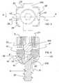
Figure 1 shows a perspective view of a polyaxial pedicle screw according to the present invention;Figure 2 shows a side view of the polyaxial pedicle screw infigure 1 ;Figure 3 shows a top view of the polyaxial pedicle screw infigure 1 ;Figure 4 shows a cross-sectional view of the polyaxial pedicle screw along a cross-section plane "A-A" identified infigure 3 ;Figure 5 shows a perspective view of the tip of an instrument adapted to act on the polyaxial pedicle screw according to the present invention;Figure 6 shows a perspective view of the polyaxial pedicle screw according to the present invention connected to the instrument tip infigure 5 ;Figure 7 shows a perspective view of a polyaxial pedicle screw according to an alternative embodiment of the present invention;Figure 8 shows a top view of the polyaxial pedicle screw of the alternative embodiment offigure 7 ;Figure 9 shows a perspective view of the tip of an instrument adapted to act on the polyaxial pedicle screw according to the invention and, in particular, on the alternative embodiment shown inFigures 7 and8 .- Referring to
figures 1-4 , apolyaxial pedicle screw 1 is illustrated according to the present invention. A plurality ofsuch screws 1, along with connectingrods 200, form a fixation system for spinal surgery, which may be sold in a kit together with a lockinginstrument 100 as depicted infigures 5-6 . - The
polyaxial pedicle screw 1 comprises ashank 3 having a threadedportion 30 and a bulgingend 31. Thescrew 1 may be cannulated or fenestrated without departing from the principles of the present invention. The screw may even be conical or straight and may be coated with an appropriate coating according to the application purposes. - The threaded
portion 30, provided with a single or multiple lead thread and ending with atip 32, is adapted for insertion and secure anchorage in the vertebral pedicle of a patient. A preferred solution is provided with a dual lead thread. The bulgingend 31 has a substantially spherical shape, with a flat distal end featuring asocket 33 able to mate with an appropriate wrench. Obviously, other alternative shapes of the bulgingend 31 may be adopted; for instance the bulgingend 31 may have a partially spherical shape or a shape that allows to pivot inside a corresponding hosting seat. - The
polyaxial pedicle screw 1 also comprises a receivinghead 2, which acts as a connecting element between the above mentionedshank 3 and a connectingrod 200, which in turn is intended to connect the polyaxial screw to one or more other screws implanted in the pedicles of neighbouring vertebrae to be fused together. Therod 200 may be substantially rigid if realized by a metal alloy or flexible if realized by a synthetic plastic material such as for instance PEEK. - The receiving
head 2 is a hollow structure, extending along a longitudinal axis x from a circularproximal aperture 20 to adistal aperture 21. It should be noted that the terms proximal and distal are used in the present document to identify the relative distance between the pedicle and the parts constituting the device described. Hence, the proximal aperture is intended to lie closer to the pedicle, while the distal aperture will be farther from it, when the pedicle screw is correctly implanted in a patient. - The
proximal aperture 20 is traversed by theshank 3. Since the diameter of theproximal aperture 20 is smaller than the diameter of the bulgingend 31 of theshank 3, said end is retained within the hollow body of the receivinghead 2, forming substantially a ball-and-socket joint 20A which allows uni-planar or poly-axial orientation of theshank 3 with respect to the receiving end. An uni-planar screw can be angulated in only one direction. As mentioned before, the shape of the bulgingend 31 allows to the allows to theshank 3 to be oriented according to the needs since the bulging end is rotatable hosted inside the hollow body of the receivinghead 2. - It should be noted that it is possible to introduce the tip of a wrench from the distal aperture and to engage the
socket 33 of the bulgingend 31, thus allowing screwing and unscrewing of theshank 3 from a patient's pedicle vertebra body. - A locking
insert 4 is housed within the receivinghead 2, and slidably movable along the longitudinal axis x of the device. The lockinginsert 4 presents amating surface 43 which is substantially spherical on its proximal side and is faced toward theproximal aperture 20. Said surface is intended to mate with the distal portion of the bulgingend 31 of the shank, so that the lockinginsert 4 may lock the relative movement of said bulgingend 31 with respect to the receivinghead 2 of the device when maintained in a locking position, i.e. pressed toward the proximal end of the receivinghead 2. The lockinginsert 4 may even be secured, for instance by a transverse pin. This would prevent disassembling of the components.The receivinghead 2 is diametrically traversed by a through bore made right above the level of its proximal end. Said through bore exhibits a cross-section roughly shaped like a round-edged square, and defines twolateral apertures 42 of the receivinghead 2. Obviously, other different and alternative shapes may be adopted without departing from the principle of the present invention. - The locking
insert 4 is housed within the diametrical through bore, exhibiting an elongated shape with twolateral arms 44 extending through thelateral apertures 42, without projecting out of the body of the receiving head. - It should be noted that the
lateral apertures 42 guide the sliding motion of the lockinginsert 4, and that the abutment of thelateral arms 44 against the periphery of said apertures conveniently restrains movement in a distal direction. - The locking
insert 4 presents a central hole in order to allow a wrench tip to reach thesocket 33 of the bulgingend 31 from thedistal aperture 21. - The distal sides of the two
lateral arms 44 of the lockinginsert 4 are conveniently flat or slightly concave, and define twocontact surfaces 41 that are faced toward thedistal aperture 21 and substantially opposed to themating surface 43. The purpose of these two contact surfaces will be explained in a following section of the present description. - The receiving
head 2 of thepolyaxial pedicle screw 1 also presents a transverseU-shaped passage 22, the purpose of which is to receive the connectingrod 200 intended to bridge thepolyaxial pedicle screw 1 to a neighbouring one. TheU-shaped passage 22 opens on the periphery of the previously defineddistal aperture 21, and is in fact defined by two U-shaped notches provided on opposite sides of the lateral rim surrounding thedistal aperture 21. - The
U-shaped passage 22 and thelateral apertures 42 extend along two orthogonal axes that are offset in the longitudinal direction. Indeed, the proximal extremity of theU-shaped passage 22 is set distally with respect to the proximal extremity of the above-mentionedlateral apertures 42, but proximally with respect to the distal extremity of saidapertures 42. - The internal surface of the lateral rim surrounding the
distal aperture 21 presents apartial thread 23, and fixing means 5 is predisposed to engage with saidpartial thread 23 in order to lock the connectingrod 200 received within the transversal U-shaped passage; said fixing means may be for instance a set-screw. The thread angle of thepartial thread 23 has been adopted to allow a fast fixing action. - Given the fact that the extension of the
U-shaped passage 22 interferes with the extension of the through bore housing the lockinginsert 4, the locking force applied to the connectingrod 200 by means of the set-screw 5 is transmitted to the locking insert and also locks the relative orientation of theshank 3 with respect to the receivinghead 2. - As discussed above, the distal extremity of the receiving
head 2 consists of a lateral rim surrounding thedistal aperture 21, which is interrupted by the two opposite notches forming theU-shaped passage 22 and which has a circular inner periphery featuring thepartial thread 23. - The outer lateral periphery of said rim has a cross-section that is roughly rectangular in shape, with bevelled edges 25. The shorter sides of the lateral periphery exhibit, on their mid-section, a lateral
longitudinal groove 26 going from the distal extremity of the receivinghead 2 to thelateral aperture 42. The laterallongitudinal grooves 26, as will be apparent from the following description, are designed to allow the introduction of twopressing arms 101 of adedicated locking instrument 100, said pressing arms traversing the grooves in order to act on thecontact surface 41 of the lockinginsert 4. In other words, the grooves define longitudinal paths for the external pressing means represented by the pressingarms 101. - Each of the four bevelled
edges 25 of the rim periphery is provided in its proximity with anindentation 24, which is designed to allow snap insertion of the lockinginstrument 100. Theseindentation 24 may have alternative shapes, for instance they may be notches, grooves or at least two holes. - The
instrument 100 comprises twolateral prongs 103 that are intended to clamp the receivinghead 2 acting on its shorter sides. Theinternal surface 102 of theprongs 103 presents a centralremovable rib 108 and four internally projectingpins 104 that are intended to cooperate with theindentations 24 of the receivinghead 2 in order to assure a stable grip of theinstrument 102 on thepolyaxial pedicle screw 1, as clearly shown inFigure 5 . Obviously, a larger or smaller number of projectingpins 104 may be provided. - A
central adjusting rod 106 is foreseen to press on theset screw 5 when theinstrument 100 is used to clamp the pedicle screw of the present invention. This adjustingrod 106 is extended parallel to thearms prongs 103 and has a free end abutting on the fixing means 5. This features allow implementing Minimal Invasive Surgery using the pedicle screw of the invention. - The
pressing arms 101 are slidably mounted on the internal side of said prongs, and are designed in such a way that when theinstrument 100 is attached to the receivinghead 2 via the pins/indentations connection, they may slide within thelongitudinal grooves 26 with theirtips 102 pressing upon thecontact surface 41 of the lockinginsert 4, keeping it in its locking position while still freely moving the rod and this is a great advantage if compared with the prior art solutions. - Now, with more specific reference to the embodiments of the
Figures 7 ,8 and9 it will be disclosed an alternative embodiment of the pedicle screw of the present invention. All the components and the portions that are structurally identical of the previously disclosed embodiment will be identified with the same reference numbers. - The screw shown in
Figure 7 has a receiving head 2' with more rounded edges if compared with the receivinghead 2 of the first embodiment. The lateral rim surrounding thedistal aperture 21 is interrupted by the two opposite notches forming theU-shaped passage 22 and the inner internal periphery presents thepartial thread 23. - The outer lateral periphery of said rim has a cross-section that is roughly circular in shape, as shown in
Figure 8 , with upper bevelled edges. - The opposite lateral
longitudinal groove 26 are extended as in the previous embodiment from the distal extremity of the receiving head 2' to thelateral aperture 42 to allow the introduction of the twopressing arms 101 of the lockinginstrument 100, as shown inFigure 9 . - The
pressing arms 101 traverse bothgrooves 26 in order to act on thecontact surface 41 of the lockinginsert 4. - Differently from the first embodiment the rim periphery is provided with indentations 24' which are located in a more central position with respect to the longitudinal extension receiving head 2', closer to the
openings 42. - The fixation system comprising the
polyaxial pedicle screw 1 according to the present invention may be implanted as follows. - After completion of the preliminary surgical phases, the
shank 3 of thepolyaxial screw 1 is inserted in a pedicle location by introducing an appropriate wrench tip (which may be the dedicated instrument 100) within thesocket 33. - Then, the surgeon orientates the receiving
head 2 or 2' in the desired angular relationship with theshank 3, possibly taking into account the position of neighbouring polyaxial screws. - Now, by means of the
pressing arms 101 of the lockinginstrument 100, it is possible to act on thelocking insert 4 in order to lock the relative orientation of the receivinghead 2 or 2'. Moreover, the adjustingrod 106 of the lockinginstrument 100 allows to keep in position the fixing means 5 without requiring a tight fixation of thepedicle screw 1. - The presence of the dedicated instrument does not prevent the insertion of a connecting rod received within the
U-shaped passage 22. On the contrary, it is still possible to block the head of thepedicle screw 1 and adjust therod 200 before fixing tight the fixing means 5. Therefore the surgeon may decide to insert such arod 200 either when the orientation of the screw is locked or when the orientation is unlocked. Moreover, it is always possible to switch between the locked and the unlocked status of the device, notwithstanding the presence of arod 200 within theU-shaped passage 22. For example, therod 200 may be inserted with a locked screw, and should the surgeon notice that the receivinghead 2 or 2' is not properly aligned with a neighbouring receiving head, it is possible to unlock the screw to correct the error. This allows a distraction of two locked screws since they could also rotate to the final position. - Finally, when the surgeon is satisfied with the layout of the fixation system, he can lock the fixing means, such as the set-
screw 5, in thedistal aperture 21 for locking both the orientation of the receivinghead 2 and the connectingrod 200. Theinstrument 100 may be safely removed after the final locking has been performed. - Obviously a person skilled in the art, in order to meet specific needs, will readily acknowledge the possibility of changes and variations to the polyaxial pedicle screw described above, all of which, however, are within the scope of protection as defined by the following claims.
- In this respect, the surface of all components such as the screw shaft, the screw head or the indentations grooves may be provided with a suitable roughness for improving gripping.
Claims (11)
- Polyaxial pedicle screw (1), comprising: a receiving head (2) longitudinally extending from a proximal aperture (20) to a distal aperture (21), said receiving head (2) comprising a transversal U-shaped passage (22), opening on the periphery of said distal aperture (21); a shank (3) traversing said proximal aperture (20), having a threaded portion (30) external to the receiving head (2) and a bulging end (31) rotatable housed within said receiving head (2); a locking insert (4) housed within said receiving head (2) and matable with said bulging end (31), said locking insert (4) being movable into a locking position wherein it locks the bulging end (31) with respect to the receiving head (2); fixing means (5) engaged in the distal aperture (21) for locking a connecting rod (200) received within said transversal U-shaped passage (22), wherein said receiving head (2) presents at least a lateral aperture (42), said lateral aperture (42) exposing a contact surface (41) of said locking insert (4) for external pressing means acting on said contact surface (41) in order to maintain the locking insert (4) into its locking position and wherein there are two lateral apertures (42) defined by a through bore diametrically traversing the receiving head (2); said locking insert (4) being housed within said through bore; the locking insert (4) exhibits an elongated shape with two lateral arms (44) extending through the lateral apertures (42), a distal side of said lateral arms (44) defining the contact surface (41);characterized in that the receiving head (2) comprises at least one lateral longitudinal groove (26) opening on said through bore, said at least one lateral longitudinal groove (26) defining longitudinal paths for the external pressing means.
- Polyaxial pedicle screw according to claim 1, wherein said lateral apertures (42) restrain the motion of the lateral arms (44) of the locking insert (4) in distal direction.
- Polyaxial pedicle screw according to one of claims 1 or 2, wherein the through bore defining the lateral apertures (42) extends along an orthogonal axis with respect to the U-shaped passage (22).
- Polyaxial pedicle screw according to claim 2, wherein the through bore defining the lateral apertures (42) is proximally offset with respect to the U-shaped passage (22).
- Polyaxial pedicle screw according to one of the preceding claims, wherein the receiving head (2) comprises a plurality of formations intended for engagement of a dedicated instrument (100) featuring the external pressing means.
- Polyaxial pedicle screw according to claim 5, wherein the formations intended for engagement of the dedicated instrument (100) are indentations (24) provided in the proximity of bevelled edges (25) of a lateral periphery of the receiving head (2).
- Polyaxial pedicle screw according to one of the preceding claims, wherein said contact surface (41) is substantially flat.
- Polyaxial pedicle screw according to one of the preceding claims, wherein a mating surface (43) of said insert (4) opposite to the contact surface (41) is concave.
- Fixation system kit comprising at least one polyaxial pedicle screw (1) according to one of the preceding claims, at least a connecting rod (200) adapted to be housed within the transversal U-shaped passage (22), and a locking instrument (100) comprising external pressing means adapted to act on said contact surface (41).
- Fixation system kit according to claim 9, wherein the locking instrument (100) comprises lateral prongs (103) adapted to clamp the receiving head (2) of the polyaxial pedicle screw (1), the external pressing means being defined by pressing arms (101) slidably mounted with respect to said lateral prongs (103).
- Fixation system kit according to claim 10, wherein said lateral prongs (103) comprise internally projecting pins (104) intended to cooperate with indentations (24) of the receiving head (2) for securing a connection between the locking instrument (100) and the receiving head (2) of the proximal pedicle screw (1).
Priority Applications (6)
| Application Number | Priority Date | Filing Date | Title |
|---|---|---|---|
| ES11159254.9TES2531645T3 (en) | 2011-03-22 | 2011-03-22 | Polyaxial pedicle screw and fixation system kit comprising said screw |
| EP11159254.9AEP2502594B1 (en) | 2011-03-22 | 2011-03-22 | Polyaxial pedicle screw and fixation system kit comprising said screw |
| AU2012201463AAU2012201463B2 (en) | 2011-03-22 | 2012-03-12 | Polyaxial pedicle screw and fixation system kit comprising said screw |
| US13/426,214US9155567B2 (en) | 2011-03-22 | 2012-03-21 | Polyaxial pedicle screw and fixation system kit comprising the screw |
| CN201210077650.7ACN102697546B (en) | 2011-03-22 | 2012-03-21 | Polyaxial pedicle screw and comprise the fixed system workbox of described screw |
| JP2012065024AJP5912056B2 (en) | 2011-03-22 | 2012-03-22 | Multi-axis pedicle screw and fixation system kit including the same |
Applications Claiming Priority (1)
| Application Number | Priority Date | Filing Date | Title |
|---|---|---|---|
| EP11159254.9AEP2502594B1 (en) | 2011-03-22 | 2011-03-22 | Polyaxial pedicle screw and fixation system kit comprising said screw |
Publications (2)
| Publication Number | Publication Date |
|---|---|
| EP2502594A1 EP2502594A1 (en) | 2012-09-26 |
| EP2502594B1true EP2502594B1 (en) | 2014-12-03 |
Family
ID=44351356
Family Applications (1)
| Application Number | Title | Priority Date | Filing Date |
|---|---|---|---|
| EP11159254.9AActiveEP2502594B1 (en) | 2011-03-22 | 2011-03-22 | Polyaxial pedicle screw and fixation system kit comprising said screw |
Country Status (6)
| Country | Link |
|---|---|
| US (1) | US9155567B2 (en) |
| EP (1) | EP2502594B1 (en) |
| JP (1) | JP5912056B2 (en) |
| CN (1) | CN102697546B (en) |
| AU (1) | AU2012201463B2 (en) |
| ES (1) | ES2531645T3 (en) |
Cited By (2)
| Publication number | Priority date | Publication date | Assignee | Title |
|---|---|---|---|---|
| DE102016114266A1 (en) | 2016-08-02 | 2018-02-08 | Silony Medical International AG | Polyaxialpedikelschraube |
| EP3745971B1 (en)* | 2018-01-31 | 2022-02-23 | Silony Medical International AG | Polyaxial screw |
Families Citing this family (49)
| Publication number | Priority date | Publication date | Assignee | Title |
|---|---|---|---|---|
| US9980753B2 (en) | 2009-06-15 | 2018-05-29 | Roger P Jackson | pivotal anchor with snap-in-place insert having rotation blocking extensions |
| US8444681B2 (en) | 2009-06-15 | 2013-05-21 | Roger P. Jackson | Polyaxial bone anchor with pop-on shank, friction fit retainer and winged insert |
| US8979904B2 (en) | 2007-05-01 | 2015-03-17 | Roger P Jackson | Connecting member with tensioned cord, low profile rigid sleeve and spacer with torsion control |
| AU2010260521C1 (en) | 2008-08-01 | 2013-08-01 | Roger P. Jackson | Longitudinal connecting member with sleeved tensioned cords |
| US11229457B2 (en) | 2009-06-15 | 2022-01-25 | Roger P. Jackson | Pivotal bone anchor assembly with insert tool deployment |
| CN103826560A (en) | 2009-06-15 | 2014-05-28 | 罗杰.P.杰克逊 | Polyaxial Bone Anchor with Socket Stem and Winged Inserts with Friction Fit Compression Collars |
| US20240341816A1 (en)* | 2009-10-05 | 2024-10-17 | Roger P. Jackson | Pivotal bone anchor assembly with temporary positional locking by tooling |
| US12383311B2 (en) | 2010-05-14 | 2025-08-12 | Roger P. Jackson | Pivotal bone anchor assembly and method for use thereof |
| US20140018867A1 (en)* | 2011-02-04 | 2014-01-16 | Stefan Freudiger | Precaution against jamming on open bone screws |
| JP5865479B2 (en)* | 2011-03-24 | 2016-02-17 | ロジャー・ピー・ジャクソン | Multiaxial bone anchor with compound joint and pop-mounted shank |
| US9060818B2 (en) | 2011-09-01 | 2015-06-23 | DePuy Synthes Products, Inc. | Bone implants |
| DE102011053295A1 (en) | 2011-09-06 | 2013-03-07 | Aesculap Ag | Polyaxial pedicle screw with provisional fixation |
| EP2574297B1 (en) | 2011-09-30 | 2015-11-11 | Biedermann Technologies GmbH & Co. KG | Bone anchoring device and tool cooperating with such a bone anchoring device |
| US8911479B2 (en) | 2012-01-10 | 2014-12-16 | Roger P. Jackson | Multi-start closures for open implants |
| US9259247B2 (en) | 2013-03-14 | 2016-02-16 | Medos International Sarl | Locking compression members for use with bone anchor assemblies and methods |
| AU2015246029B2 (en)* | 2014-04-10 | 2018-11-29 | Medacta International Sa | Device for fixing surgical implants in place and relative assembly procedure with anchoring means |
| US10064658B2 (en) | 2014-06-04 | 2018-09-04 | Roger P. Jackson | Polyaxial bone anchor with insert guides |
| AU2015294996B2 (en)* | 2014-07-30 | 2018-05-17 | Medacta International Sa | Polyaxial screw for surgical implant |
| US10543021B2 (en) | 2014-10-21 | 2020-01-28 | Roger P. Jackson | Pivotal bone anchor assembly having an open ring positioner for a retainer |
| US11219471B2 (en) | 2014-10-21 | 2022-01-11 | Roger P. Jackson | Pivotal bone anchor receiver having an insert with post-placement tool deployment |
| US10555818B2 (en) | 2015-04-23 | 2020-02-11 | Institute for Musculoskeletal Science and Education, Ltd. | Spinal fusion implant for oblique insertion |
| US9707013B2 (en)* | 2015-04-30 | 2017-07-18 | Warsaw Orthopedic, Inc. | Spinal implant system and methods of use |
| DE102015109481A1 (en)* | 2015-06-15 | 2016-12-15 | Aesculap Ag | Pedicle screw with radially offset guide |
| EP3120791B1 (en) | 2015-07-24 | 2017-11-22 | Biedermann Technologies GmbH & Co. KG | Polyaxial bone anchoring device and instrument for use with the same |
| CN105596071B (en)* | 2015-12-31 | 2018-03-23 | 何静 | A kind of dual-purpose pedicle nail |
| US10568667B2 (en) | 2016-07-13 | 2020-02-25 | Medos International Sàrl | Bone anchor assemblies and related instrumentation |
| US10874438B2 (en) | 2016-07-13 | 2020-12-29 | Medos International Sarl | Bone anchor assemblies and related instrumentation |
| US10463402B2 (en) | 2016-07-13 | 2019-11-05 | Medos International Sàrl | Bone anchor assemblies and related instrumentation |
| US10363073B2 (en) | 2016-07-13 | 2019-07-30 | Medos International Sàrl | Bone anchor assemblies and related instrumentation |
| US10966762B2 (en) | 2017-12-15 | 2021-04-06 | Medos International Sarl | Unilateral implant holders and related methods |
| EP3510954B1 (en) | 2018-01-10 | 2021-07-28 | Biedermann Technologies GmbH & Co. KG | Polyaxial bone anchoring device and system of an instrument and a polyaxial bone anchoring device |
| US11596449B2 (en) | 2018-09-13 | 2023-03-07 | Roger P. Jackson | Pivotal bone anchor assembly with modular receiver and universal shank head |
| WO2020102787A1 (en) | 2018-11-16 | 2020-05-22 | Surber, James L. | Pivotal bone anchor assembly having a deployable collet insert with internal pressure ring |
| US11291481B2 (en) | 2019-03-21 | 2022-04-05 | Medos International Sarl | Rod reducers and related methods |
| USD1004774S1 (en) | 2019-03-21 | 2023-11-14 | Medos International Sarl | Kerrison rod reducer |
| US11291482B2 (en) | 2019-03-21 | 2022-04-05 | Medos International Sarl | Rod reducers and related methods |
| EP3785649B1 (en) | 2019-08-30 | 2022-08-03 | Biedermann Technologies GmbH & Co. KG | Bone anchoring device |
| WO2021127251A1 (en) | 2019-12-17 | 2021-06-24 | Jackson Roger P | Bone anchor assembly with closed ring retainer and internal snap ring |
| WO2021263088A1 (en) | 2020-06-26 | 2021-12-30 | K2M, Inc. | Modular head assembly |
| EP3988040B1 (en) | 2020-10-22 | 2025-09-03 | Biedermann Technologies GmbH & Co. KG | Coupling device for coupling a rod to a bone anchor |
| IL302256A (en)* | 2020-10-23 | 2023-06-01 | Carbofix Spine Inc | The devices are made of a composite material for connecting an orthopedic rod to a pedicle screw and complementary tools |
| EP4240262B1 (en) | 2020-11-09 | 2024-12-04 | Medos International Sàrl | Biplanar forceps reducers |
| WO2022108875A1 (en) | 2020-11-19 | 2022-05-27 | K2M, Inc. | Modular head assembly for spinal fixation |
| US12364515B2 (en) | 2021-03-05 | 2025-07-22 | Medos International Sàrl | Multi-feature polyaxial screw |
| WO2022184797A1 (en) | 2021-03-05 | 2022-09-09 | Medos International Sarl | Selectively locking polyaxial screw |
| DE102022108980A1 (en)* | 2021-04-13 | 2022-10-13 | ORTHO HUB VENTURES UG (haftungsbeschränkt) | Osteosynthesis device, in particular for treating the spine, and fastening system for the same |
| US11751915B2 (en) | 2021-07-09 | 2023-09-12 | Roger P. Jackson | Modular spinal fixation system with bottom-loaded universal shank heads |
| USD1069121S1 (en)* | 2022-06-01 | 2025-04-01 | Curiteva, Inc. | Pedicle screw |
| US12329479B2 (en)* | 2022-10-28 | 2025-06-17 | Warsaw Orthopedic, Inc. | Systems and methods for setting an implant |
Family Cites Families (19)
| Publication number | Priority date | Publication date | Assignee | Title |
|---|---|---|---|---|
| DE4307576C1 (en) | 1993-03-10 | 1994-04-21 | Biedermann Motech Gmbh | Bone screw esp. for spinal column correction - has U=shaped holder section for receiving straight or bent rod |
| DE19507141B4 (en) | 1995-03-01 | 2004-12-23 | Harms, Jürgen, Prof. Dr.med. | Locking |
| DE19509332C1 (en) | 1995-03-15 | 1996-08-14 | Harms Juergen | Anchoring element |
| CN1142746C (en)* | 1996-12-12 | 2004-03-24 | 库尔斯恩蒂斯股份公司 | Device for connecting longitudinal support to pedicle screw |
| ES2191775T3 (en) | 1996-12-12 | 2003-09-16 | Synthes Ag | DEVICE FOR CONNECTING A LONGITUDINAL SUPPORT WITH A PEDICULAR SCREW. |
| US5776135A (en) | 1996-12-23 | 1998-07-07 | Third Millennium Engineering, Llc | Side mounted polyaxial pedicle screw |
| US6558382B2 (en)* | 2000-04-27 | 2003-05-06 | Medtronic, Inc. | Suction stabilized epicardial ablation devices |
| DE10157814B4 (en) | 2001-11-27 | 2004-12-02 | Biedermann Motech Gmbh | Closure device for securing a rod-shaped element in a holding element connected to a shaft |
| US6837889B2 (en)* | 2002-03-01 | 2005-01-04 | Endius Incorporated | Apparatus for connecting a longitudinal member to a bone portion |
| US7066937B2 (en)* | 2002-02-13 | 2006-06-27 | Endius Incorporated | Apparatus for connecting a longitudinal member to a bone portion |
| US7621918B2 (en)* | 2004-11-23 | 2009-11-24 | Jackson Roger P | Spinal fixation tool set and method |
| US7588575B2 (en)* | 2003-10-21 | 2009-09-15 | Innovative Spinal Technologies | Extension for use with stabilization systems for internal structures |
| US9980753B2 (en)* | 2009-06-15 | 2018-05-29 | Roger P Jackson | pivotal anchor with snap-in-place insert having rotation blocking extensions |
| WO2008008511A2 (en)* | 2006-07-14 | 2008-01-17 | Laszlo Garamszegi | Pedicle screw assembly with inclined surface seat |
| AU2010260521C1 (en)* | 2008-08-01 | 2013-08-01 | Roger P. Jackson | Longitudinal connecting member with sleeved tensioned cords |
| US8506601B2 (en)* | 2008-10-14 | 2013-08-13 | Pioneer Surgical Technology, Inc. | Low profile dual locking fixation system and offset anchor member |
| US20130131730A1 (en)* | 2009-06-15 | 2013-05-23 | Roger P. Jackson | Polyaxial bone anchor with articulating retainer and multi-start closure |
| EP2485654B1 (en)* | 2009-10-05 | 2021-05-05 | Jackson P. Roger | Polyaxial bone anchor with non-pivotable retainer and pop-on shank, some with friction fit |
| US10172647B2 (en)* | 2009-11-16 | 2019-01-08 | Nexxt Spine, LLC | Poly-axial implant fixation system |
- 2011
- 2011-03-22EPEP11159254.9Apatent/EP2502594B1/enactiveActive
- 2011-03-22ESES11159254.9Tpatent/ES2531645T3/enactiveActive
- 2012
- 2012-03-12AUAU2012201463Apatent/AU2012201463B2/enactiveActive
- 2012-03-21CNCN201210077650.7Apatent/CN102697546B/ennot_activeExpired - Fee Related
- 2012-03-21USUS13/426,214patent/US9155567B2/enactiveActive
- 2012-03-22JPJP2012065024Apatent/JP5912056B2/enactiveActive
Cited By (4)
| Publication number | Priority date | Publication date | Assignee | Title |
|---|---|---|---|---|
| DE102016114266A1 (en) | 2016-08-02 | 2018-02-08 | Silony Medical International AG | Polyaxialpedikelschraube |
| WO2018024414A1 (en) | 2016-08-02 | 2018-02-08 | Silony Medical International AG | Polyaxial pedicle screw |
| EP3620126A1 (en) | 2016-08-02 | 2020-03-11 | Silony Medical International AG | Polyaxial pedicle screw |
| EP3745971B1 (en)* | 2018-01-31 | 2022-02-23 | Silony Medical International AG | Polyaxial screw |
Also Published As
| Publication number | Publication date |
|---|---|
| US20120245640A1 (en) | 2012-09-27 |
| US9155567B2 (en) | 2015-10-13 |
| EP2502594A1 (en) | 2012-09-26 |
| CN102697546B (en) | 2016-06-29 |
| JP5912056B2 (en) | 2016-04-27 |
| AU2012201463B2 (en) | 2015-01-22 |
| CN102697546A (en) | 2012-10-03 |
| AU2012201463A1 (en) | 2012-10-11 |
| ES2531645T3 (en) | 2015-03-18 |
| JP2012196453A (en) | 2012-10-18 |
Similar Documents
| Publication | Publication Date | Title |
|---|---|---|
| EP2502594B1 (en) | Polyaxial pedicle screw and fixation system kit comprising said screw | |
| US12076060B2 (en) | Derotation apparatus for treating spinal irregularities | |
| US11607252B2 (en) | Modular uniplanar pedicle screw assembly for use with a polyaxial bone fastener | |
| US11490931B2 (en) | Systems and methods for correcting spinal deformities | |
| US10751093B2 (en) | Pivotal bone anchor assembly with snap-in-place bushing having resilient alignment tabs and shank head engaging slots | |
| EP2467076B1 (en) | Transverse rod connector | |
| US7476240B2 (en) | Devices and methods for inserting a spinal fixation element | |
| US9788869B2 (en) | Spinal fixation element rotation instrument | |
| US8690923B2 (en) | Bone fixation systems and methods | |
| US20160192965A1 (en) | Polyaxial bone anchoring device with enlarged pivot angle | |
| US11224462B2 (en) | Coupling device, in particular for use in orthopedic surgery | |
| US20100004694A1 (en) | Screw assembly | |
| EP4301257B1 (en) | Multi-feature polyaxial screw | |
| US12193714B2 (en) | Connectors, systems, and methods thereof | |
| AU2014321490A1 (en) | Transverse coupler adjuster spinal correction systems and methods |
Legal Events
| Date | Code | Title | Description |
|---|---|---|---|
| PUAI | Public reference made under article 153(3) epc to a published international application that has entered the european phase | Free format text:ORIGINAL CODE: 0009012 | |
| AK | Designated contracting states | Kind code of ref document:A1 Designated state(s):AL AT BE BG CH CY CZ DE DK EE ES FI FR GB GR HR HU IE IS IT LI LT LU LV MC MK MT NL NO PL PT RO RS SE SI SK SM TR | |
| AX | Request for extension of the european patent | Extension state:BA ME | |
| 17P | Request for examination filed | Effective date:20130326 | |
| 17Q | First examination report despatched | Effective date:20130502 | |
| GRAP | Despatch of communication of intention to grant a patent | Free format text:ORIGINAL CODE: EPIDOSNIGR1 | |
| INTG | Intention to grant announced | Effective date:20140718 | |
| GRAS | Grant fee paid | Free format text:ORIGINAL CODE: EPIDOSNIGR3 | |
| GRAA | (expected) grant | Free format text:ORIGINAL CODE: 0009210 | |
| AK | Designated contracting states | Kind code of ref document:B1 Designated state(s):AL AT BE BG CH CY CZ DE DK EE ES FI FR GB GR HR HU IE IS IT LI LT LU LV MC MK MT NL NO PL PT RO RS SE SI SK SM TR | |
| AX | Request for extension of the european patent | Extension state:BA ME | |
| REG | Reference to a national code | Ref country code:GB Ref legal event code:FG4D | |
| REG | Reference to a national code | Ref country code:AT Ref legal event code:REF Ref document number:698900 Country of ref document:AT Kind code of ref document:T Effective date:20141215 Ref country code:CH Ref legal event code:EP | |
| REG | Reference to a national code | Ref country code:IE Ref legal event code:FG4D | |
| REG | Reference to a national code | Ref country code:DE Ref legal event code:R096 Ref document number:602011011837 Country of ref document:DE Effective date:20150115 | |
| REG | Reference to a national code | Ref country code:CH Ref legal event code:NV Representative=s name:BUGNION S.A., CH | |
| REG | Reference to a national code | Ref country code:NL Ref legal event code:T3 | |
| REG | Reference to a national code | Ref country code:ES Ref legal event code:FG2A Ref document number:2531645 Country of ref document:ES Kind code of ref document:T3 Effective date:20150318 | |
| REG | Reference to a national code | Ref country code:AT Ref legal event code:MK05 Ref document number:698900 Country of ref document:AT Kind code of ref document:T Effective date:20141203 | |
| PG25 | Lapsed in a contracting state [announced via postgrant information from national office to epo] | Ref country code:FI Free format text:LAPSE BECAUSE OF FAILURE TO SUBMIT A TRANSLATION OF THE DESCRIPTION OR TO PAY THE FEE WITHIN THE PRESCRIBED TIME-LIMIT Effective date:20141203 Ref country code:LT Free format text:LAPSE BECAUSE OF FAILURE TO SUBMIT A TRANSLATION OF THE DESCRIPTION OR TO PAY THE FEE WITHIN THE PRESCRIBED TIME-LIMIT Effective date:20141203 Ref country code:NO Free format text:LAPSE BECAUSE OF FAILURE TO SUBMIT A TRANSLATION OF THE DESCRIPTION OR TO PAY THE FEE WITHIN THE PRESCRIBED TIME-LIMIT Effective date:20150303 | |
| REG | Reference to a national code | Ref country code:LT Ref legal event code:MG4D | |
| PG25 | Lapsed in a contracting state [announced via postgrant information from national office to epo] | Ref country code:GR Free format text:LAPSE BECAUSE OF FAILURE TO SUBMIT A TRANSLATION OF THE DESCRIPTION OR TO PAY THE FEE WITHIN THE PRESCRIBED TIME-LIMIT Effective date:20150304 Ref country code:LV Free format text:LAPSE BECAUSE OF FAILURE TO SUBMIT A TRANSLATION OF THE DESCRIPTION OR TO PAY THE FEE WITHIN THE PRESCRIBED TIME-LIMIT Effective date:20141203 Ref country code:SE Free format text:LAPSE BECAUSE OF FAILURE TO SUBMIT A TRANSLATION OF THE DESCRIPTION OR TO PAY THE FEE WITHIN THE PRESCRIBED TIME-LIMIT Effective date:20141203 Ref country code:CY Free format text:LAPSE BECAUSE OF FAILURE TO SUBMIT A TRANSLATION OF THE DESCRIPTION OR TO PAY THE FEE WITHIN THE PRESCRIBED TIME-LIMIT Effective date:20141203 Ref country code:RS Free format text:LAPSE BECAUSE OF FAILURE TO SUBMIT A TRANSLATION OF THE DESCRIPTION OR TO PAY THE FEE WITHIN THE PRESCRIBED TIME-LIMIT Effective date:20141203 Ref country code:AT Free format text:LAPSE BECAUSE OF FAILURE TO SUBMIT A TRANSLATION OF THE DESCRIPTION OR TO PAY THE FEE WITHIN THE PRESCRIBED TIME-LIMIT Effective date:20141203 Ref country code:HR Free format text:LAPSE BECAUSE OF FAILURE TO SUBMIT A TRANSLATION OF THE DESCRIPTION OR TO PAY THE FEE WITHIN THE PRESCRIBED TIME-LIMIT Effective date:20141203 | |
| PG25 | Lapsed in a contracting state [announced via postgrant information from national office to epo] | Ref country code:EE Free format text:LAPSE BECAUSE OF FAILURE TO SUBMIT A TRANSLATION OF THE DESCRIPTION OR TO PAY THE FEE WITHIN THE PRESCRIBED TIME-LIMIT Effective date:20141203 Ref country code:RO Free format text:LAPSE BECAUSE OF FAILURE TO SUBMIT A TRANSLATION OF THE DESCRIPTION OR TO PAY THE FEE WITHIN THE PRESCRIBED TIME-LIMIT Effective date:20141203 Ref country code:SK Free format text:LAPSE BECAUSE OF FAILURE TO SUBMIT A TRANSLATION OF THE DESCRIPTION OR TO PAY THE FEE WITHIN THE PRESCRIBED TIME-LIMIT Effective date:20141203 Ref country code:CZ Free format text:LAPSE BECAUSE OF FAILURE TO SUBMIT A TRANSLATION OF THE DESCRIPTION OR TO PAY THE FEE WITHIN THE PRESCRIBED TIME-LIMIT Effective date:20141203 Ref country code:PT Free format text:LAPSE BECAUSE OF FAILURE TO SUBMIT A TRANSLATION OF THE DESCRIPTION OR TO PAY THE FEE WITHIN THE PRESCRIBED TIME-LIMIT Effective date:20150403 | |
| PG25 | Lapsed in a contracting state [announced via postgrant information from national office to epo] | Ref country code:PL Free format text:LAPSE BECAUSE OF FAILURE TO SUBMIT A TRANSLATION OF THE DESCRIPTION OR TO PAY THE FEE WITHIN THE PRESCRIBED TIME-LIMIT Effective date:20141203 Ref country code:IS Free format text:LAPSE BECAUSE OF FAILURE TO SUBMIT A TRANSLATION OF THE DESCRIPTION OR TO PAY THE FEE WITHIN THE PRESCRIBED TIME-LIMIT Effective date:20150403 | |
| REG | Reference to a national code | Ref country code:DE Ref legal event code:R097 Ref document number:602011011837 Country of ref document:DE | |
| PLBE | No opposition filed within time limit | Free format text:ORIGINAL CODE: 0009261 | |
| STAA | Information on the status of an ep patent application or granted ep patent | Free format text:STATUS: NO OPPOSITION FILED WITHIN TIME LIMIT | |
| PG25 | Lapsed in a contracting state [announced via postgrant information from national office to epo] | Ref country code:DK Free format text:LAPSE BECAUSE OF FAILURE TO SUBMIT A TRANSLATION OF THE DESCRIPTION OR TO PAY THE FEE WITHIN THE PRESCRIBED TIME-LIMIT Effective date:20141203 Ref country code:MC Free format text:LAPSE BECAUSE OF FAILURE TO SUBMIT A TRANSLATION OF THE DESCRIPTION OR TO PAY THE FEE WITHIN THE PRESCRIBED TIME-LIMIT Effective date:20141203 | |
| 26N | No opposition filed | Effective date:20150904 | |
| REG | Reference to a national code | Ref country code:IE Ref legal event code:MM4A | |
| PG25 | Lapsed in a contracting state [announced via postgrant information from national office to epo] | Ref country code:IE Free format text:LAPSE BECAUSE OF NON-PAYMENT OF DUE FEES Effective date:20150322 | |
| PG25 | Lapsed in a contracting state [announced via postgrant information from national office to epo] | Ref country code:SI Free format text:LAPSE BECAUSE OF FAILURE TO SUBMIT A TRANSLATION OF THE DESCRIPTION OR TO PAY THE FEE WITHIN THE PRESCRIBED TIME-LIMIT Effective date:20141203 | |
| REG | Reference to a national code | Ref country code:FR Ref legal event code:PLFP Year of fee payment:6 | |
| PG25 | Lapsed in a contracting state [announced via postgrant information from national office to epo] | Ref country code:MT Free format text:LAPSE BECAUSE OF FAILURE TO SUBMIT A TRANSLATION OF THE DESCRIPTION OR TO PAY THE FEE WITHIN THE PRESCRIBED TIME-LIMIT Effective date:20141203 | |
| REG | Reference to a national code | Ref country code:FR Ref legal event code:PLFP Year of fee payment:7 | |
| PG25 | Lapsed in a contracting state [announced via postgrant information from national office to epo] | Ref country code:BG Free format text:LAPSE BECAUSE OF FAILURE TO SUBMIT A TRANSLATION OF THE DESCRIPTION OR TO PAY THE FEE WITHIN THE PRESCRIBED TIME-LIMIT Effective date:20141203 Ref country code:SM Free format text:LAPSE BECAUSE OF FAILURE TO SUBMIT A TRANSLATION OF THE DESCRIPTION OR TO PAY THE FEE WITHIN THE PRESCRIBED TIME-LIMIT Effective date:20141203 Ref country code:HU Free format text:LAPSE BECAUSE OF FAILURE TO SUBMIT A TRANSLATION OF THE DESCRIPTION OR TO PAY THE FEE WITHIN THE PRESCRIBED TIME-LIMIT; INVALID AB INITIO Effective date:20110322 | |
| PG25 | Lapsed in a contracting state [announced via postgrant information from national office to epo] | Ref country code:TR Free format text:LAPSE BECAUSE OF FAILURE TO SUBMIT A TRANSLATION OF THE DESCRIPTION OR TO PAY THE FEE WITHIN THE PRESCRIBED TIME-LIMIT Effective date:20141203 | |
| REG | Reference to a national code | Ref country code:FR Ref legal event code:PLFP Year of fee payment:8 | |
| PG25 | Lapsed in a contracting state [announced via postgrant information from national office to epo] | Ref country code:MK Free format text:LAPSE BECAUSE OF FAILURE TO SUBMIT A TRANSLATION OF THE DESCRIPTION OR TO PAY THE FEE WITHIN THE PRESCRIBED TIME-LIMIT Effective date:20141203 | |
| PG25 | Lapsed in a contracting state [announced via postgrant information from national office to epo] | Ref country code:AL Free format text:LAPSE BECAUSE OF FAILURE TO SUBMIT A TRANSLATION OF THE DESCRIPTION OR TO PAY THE FEE WITHIN THE PRESCRIBED TIME-LIMIT Effective date:20141203 | |
| PGFP | Annual fee paid to national office [announced via postgrant information from national office to epo] | Ref country code:NL Payment date:20220325 Year of fee payment:12 Ref country code:LU Payment date:20220228 Year of fee payment:12 Ref country code:BE Payment date:20220325 Year of fee payment:12 | |
| P01 | Opt-out of the competence of the unified patent court (upc) registered | Effective date:20230628 | |
| REG | Reference to a national code | Ref country code:NL Ref legal event code:MM Effective date:20230401 | |
| REG | Reference to a national code | Ref country code:BE Ref legal event code:MM Effective date:20230331 | |
| PG25 | Lapsed in a contracting state [announced via postgrant information from national office to epo] | Ref country code:NL Free format text:LAPSE BECAUSE OF NON-PAYMENT OF DUE FEES Effective date:20230401 Ref country code:LU Free format text:LAPSE BECAUSE OF NON-PAYMENT OF DUE FEES Effective date:20230322 | |
| PG25 | Lapsed in a contracting state [announced via postgrant information from national office to epo] | Ref country code:BE Free format text:LAPSE BECAUSE OF NON-PAYMENT OF DUE FEES Effective date:20230331 | |
| PGFP | Annual fee paid to national office [announced via postgrant information from national office to epo] | Ref country code:DE Payment date:20250327 Year of fee payment:15 | |
| PGFP | Annual fee paid to national office [announced via postgrant information from national office to epo] | Ref country code:FR Payment date:20250324 Year of fee payment:15 | |
| PGFP | Annual fee paid to national office [announced via postgrant information from national office to epo] | Ref country code:GB Payment date:20250325 Year of fee payment:15 | |
| PGFP | Annual fee paid to national office [announced via postgrant information from national office to epo] | Ref country code:ES Payment date:20250415 Year of fee payment:15 | |
| PGFP | Annual fee paid to national office [announced via postgrant information from national office to epo] | Ref country code:IT Payment date:20250327 Year of fee payment:15 | |
| PGFP | Annual fee paid to national office [announced via postgrant information from national office to epo] | Ref country code:CH Payment date:20250401 Year of fee payment:15 |